optimal gait for bioinspired climbing robots using dry
TRANSCRIPT

This is a pre-print of an article published in: Journal of Bionic Engineering, Volume 10, Issue 1, January 2013, Pages 1-11.
Final version available at: https://doi.org/10.1016/S1672-6529(13)60193-6
Optimal gait for bioinspired climbing robots using
dry adhesion: a quasi-static investigation
P. Boscariol, M. Henrey, Y. Li, C. Menon*
MENRVA Research Group, Simon Fraser University, Vancouver, Canada;
School of Engineering Science
Abstract
Legged robots relying on dry adhesives for vertical climbing are required to preload their
feet against the wall to increase contact surface area and consequently maximize
adhesion force. Preloading a foot causes a redistribution of forces in the entire robot,
including contact forces between the other feet and the wall. An inappropriate
redistribution of these forces can cause irreparable detachment of the robot from the
vertical surface. This paper investigates an optimal preloading and detaching strategy
that minimizes energy consumption, while retaining safety, during locomotion on
vertical surfaces. The gait of a six-legged robot is planned using a quasi-static model that
takes into account both the structure of the robot and the characteristics of the adhesive
material. The latter was modelled from experimental data collected for this paper. A
constrained optimization routine is used, and its output is a sequence of optimal posture
and motor torque set-points.
Keywords: climbing robot; dry adhesive; gait planning; legged robots; preloading;
1 Introduction
In recent years, properties of engineered (artificial) dry adhesives[1] have been investigated for
the design of innovative climbing robots[2-4]. Most of the works, which were carried out in the wake of
recent biological studies on geckos[5] and spiders[6-8], aimed to design autonomous robots which were
able to climb vertical surfaces without the use of special gripping tools[9],magnetic devices[10,11], or
suction cups[12,13]. By taking inspiration from nature, artificial dry adhesives were prototyped and used
for the design of innovative climbing robots. Some working prototypes of climbing robots relying on
dry adhesives were developed[2,9,14-17].
This paper focuses on the development of a safe and efficient climbing gait to be used by legged
climbing robots[14,15]. Gait planning is a topic of uttermost importance – attachment failure is
catastrophic for climbing robots. It should be noted that gait planning for legged climbing robots has
some distinctive features when compared to the gait planning for legged robots walking or running on
horizontal surfaces. The direction of the gravity force acting on a robot on a vertical or overhanging
wall is different from the direction of the gravity force acting on a robot on a horizontal surface,
requiring therefore a different locomotion strategy. In this paper, energy efficiency and safety are of
interest because they allow a robot to maximize its travelling distance and avoid detachment when
climbing a vertical wall. The literature on gait planning of legged robots focuses mainly on walking[16]
and running[19] on horizontal surfaces. The study of locomotion of legged systems on horizontal
surfaces was pioneered by Hildebrand[20], who proposed a set of possible gaits obtained by combining
sequences of swing and stance phases. The approach proposed by Hildebrand, which is quite general
and widely used, is not suitable for designing the gait of legged climbing robots relying on dry
adhesives. As shown in the following sections of this paper, experimental results show that the

This is a pre-print of an article published in: Journal of Bionic Engineering, Volume 10, Issue 1, January 2013, Pages 1-11.
Final version available at: https://doi.org/10.1016/S1672-6529(13)60193-6
directional adhesion properties of dry adhesives require an optimized distribution of forces on the
robot’s feet in order to avoid unintentional detachment. Contrasted with the two phases (swing and
stance) characterizing locomotion on a horizontal surface, climbing a vertical surface with synthetic
dry adhesives requires the following four phases: (1) detachment; (2) swing; (3) preload; and (4)
stance. During the detachment phase, one leg pulls its adhesive off the surface thus inducing an
additional load on the remaining feet in contact to the surface. On the other hand, during the preload
phase one leg preloads its adhesive pad against the surface, as required to maximise contact surface
area of the adhesive[21,22], therefore causing a redistribution (overall decrease) of pressure in the other
feet which are contacting the surface. This pressure redistribution during the detachment and
preloading phases is a function of both the configuration of the robot (e.g. joint angles and position of
the feet) and the inclination of the surface.
There are a few notable examples of work on estimating the optimal force distribution in legged
robots[23-26]. Chen et al.[24] performed a very comprehensive work by exploring several optimization
targets for the design of a gait suitable for four-legged robots crawling on a horizontal surface. Vidoni
and Gasparetto[23] investigated the kinematics of Evarcha Arcuata spiders and developed a static model
of adhesion for evaluating an optimal force distribution that did not violate the static equilibrium of
forces and moments. Pretto et al.[25] used the experimental results on adhesive properties of
Polydimethylsiloxane (PDMS) structured samples to study the motion of a six-legged robot within a
multi-body simulation environment.
Concerning adhesion, several models describing adhesive properties of different materials have
been proposed. For example, Murphy et al.[26] investigated hierarchical structured materials inspired by
the adhesives found on the feet of geckos. A point-wise model of adhesion for elastic PDMS adhesives
has been developed[25]. Santos et al.[27] experimentally measured a limit surface for synthetic directional
dry adhesives, characterizing which force vectors the adhesives can sustain before failure. The effects
of peeling on adhesive pads similar to those used in this work have been presented[28], however this
work explores detachment without peeling. Parameters considered in this work are the direction of the
detaching force and the ratio between pull-off force and preload.
This paper is structured as follows: the first part of the paper investigates the physical structure
and directional adhesion properties of dual-layer PDMS adhesives. Results obtained are used to
develop a static model of adhesion. Then the features of software designed to simulate a generic six-
legged, 18 degree-of-freedom (DOF) climbing robot with are presented. This simulator takes into
account both the adhesion model proposed in this work and the constraints imposed by the structure
and actuators of a legged robot. This work concludes by presenting an optimization procedure used for
both assessing the feasibility of arbitrary gait patterns and estimating the optimal posture and
force/torque distribution for optimal climbing.
2 PDMS dry adhesive: mechanical model
PDMS artificial dry adhesives were fabricated following the manufacturing procedure presented
by Li et al.[28]. In contrast with the work by Li et al.[28], for this study the layer in contact with the
vertical wall was a continuous adhesive thin film, as shown in Fig. 1. Samples were made in a square
with an area of 1cm2. The setup schematically represented in Fig. 2a was used for characterizing the
mechanical properties of the adhesives. The linear stage used was a high-precision Zaber T-LS28M-S
and the load cell was a Futek LSM300 rated at 44.5 N. LabVIEW software was used for data
acquisition and stage control. Adhesion was tested against a 3 mm thick, smooth, Poly(methyl
methacrylate) (PMMA) substrate, which was mounted on a rigid holder; flexural behaviour of the
PMMA surface was negligible. The adhesive samples were attached with silicone (Dow Corning 732)
on a mounting device, which was connected to the linear stage using a rigid aluminium link (see Fig.
2b). The link and the sample holder were connected using a universal joint.

This is a pre-print of an article published in: Journal of Bionic Engineering, Volume 10, Issue 1, January 2013, Pages 1-11.
Final version available at: https://doi.org/10.1016/S1672-6529(13)60193-6
Figure 1: Dual-layer PDMS adhesive (square, 1x1 cm2) mounted on the sample holder. a) top view; b)
side view.
For our particular structured adhesives, two sets of tests were carried out. The first test (Test I)
aimed to experimentally identify the ratio between the preload and the pull-off force. The second test
(Test II) aimed to measure the force required to detach the PDMS sample from the PMMA surface, as a
function of the angle between the pull-off force and the plane of adhesion. This angle is indicated as α
in Fig. 2a.
Figure 2: Experimental setup. a) schematics and notation of parameters; b) actual experimental setup.
2.1 Test I
The load cell was used for measuring the detachment forces and controlling the imposed preload
forces. For the first set of tests, the PDMS sample was preloaded with a set of fixed forces acting
normally on the PMMA surface. Subsequently, the linear stage retracted with a constant speed of
200 µm/s while the detaching force was measured and recorded. For each preload force, 10 detachment
trials were performed and the two extreme recorded values discarded. The results presented in Fig. 3
This is a pre-print of an article published in: Journal of Bionic Engineering, Volume 10, Issue 1, January 2013, Pages 1-11.
Final version available at: https://doi.org/10.1016/S1672-6529(13)60193-6
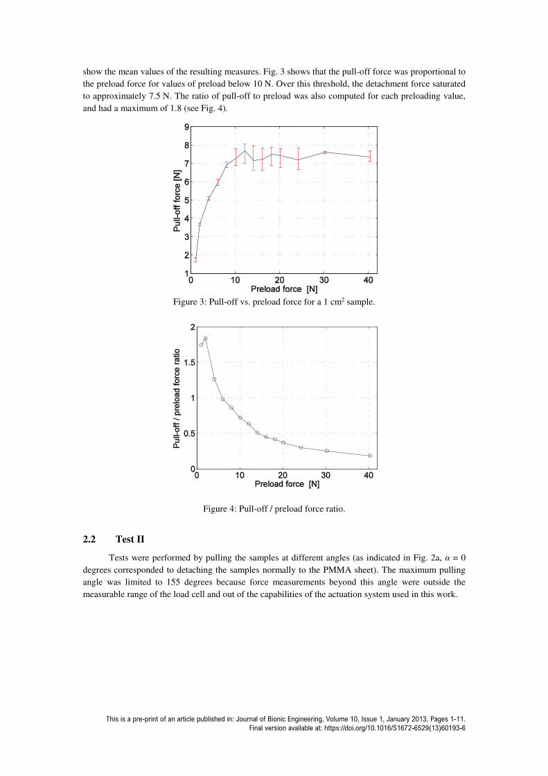
show the mean values of the resulting measures. Fig. 3 shows that the pull-off force was proportional to
the preload force for values of preload below 10 N. Over this threshold, the detachment force saturated
to approximately 7.5 N. The ratio of pull-off to preload was also computed for each preloading value,
and had a maximum of 1.8 (see Fig. 4).
Figure 3: Pull-off vs. preload force for a 1 cm2 sample.
Figure 4: Pull-off / preload force ratio.
2.2 Test II
Tests were performed by pulling the samples at different angles (as indicated in Fig. 2a, α = 0
degrees corresponded to detaching the samples normally to the PMMA sheet). The maximum pulling
angle was limited to 155 degrees because force measurements beyond this angle were outside the
measurable range of the load cell and out of the capabilities of the actuation system used in this work.

This is a pre-print of an article published in: Journal of Bionic Engineering, Volume 10, Issue 1, January 2013, Pages 1-11.
Final version available at: https://doi.org/10.1016/S1672-6529(13)60193-6
Figure 5: Measured pull-off force for a 1 cm2 sample.
As previously discussed, a preload force of 10 N had a saturation effect on the pull-off force.
Therefore all the tests conducted for producing the graph in Fig. 5 were performed using a manual
preload which exceeded the 10 N threshold. The resulting limited variance of recorded data shows that
the procedure was sufficiently accurate and repeatable for the purpose of this work. As shown in Fig. 5,
the detachment force was largely affected by the direction of the force. Minimum detachment force
occurred at α = 50 degrees, while the maximum value for small angles was found to be at α = 10
degrees. The detachment force increased rapidly for values of α larger than 150 degrees. From this
data, it can be inferred that the intentional detachment should be performed by exerting a force with
α = 50 degrees.
3 Gait planning algorithm
In this section, a novel approach to design optimal and feasible gaits for legged climbing robots
is presented. The basic concept used was to separate each step into the four phases that were previously
introduced, namely detachment, swing, preload, and stance. Each phase can be seen as a distinct
optimization problem. For each phase, optimal posture and optimal torque distribution were
determined. Optimality is desirable to obtain efficiency, which can be interpreted as minimization of
power consumption. One constraint is maintaining safety, defined as the difference between the
adhesion strength and the forces acting on the adhesive, which could lead to an unintentional foot
detachment. Feasibility of the optimal solution should be verified a posteriori, since the complexity of
the force equilibrium problem prevents defining a priori general rules that guarantee feasibility of the
solution. It should be noted that both simulation and experimental tests showed that accidental
detachment of the robot from a vertical surface could be induced by the variation of the force
distribution generated during the detachment phase. This specific problem is addressed during the
generation of the gait planning.
3.1 The static equilibrium problem
The proposed gait optimization procedure requires the definition and solution of the static
equilibrium of generalized forces for a legged robot attached to a vertical surface. In this work, the
vector of joint positions is defined as:
= , , , … , , , (1)
where qi,j is the vector of the positions of the i-th joint of the j-th leg of a robot with 3 joints and n legs.
The posture of the robot is described by:

This is a pre-print of an article published in: Journal of Bionic Engineering, Volume 10, Issue 1, January 2013, Pages 1-11.
Final version available at: https://doi.org/10.1016/S1672-6529(13)60193-6
= (2)
where xB, yB and zB are the Cartesian positions of the centre of mass of the body, and ϕB, θB and φB are
the roll, pitch, and yaw angles that define univocally the rotation of the body measured in a global
reference frame X,Y,Z. The vector of forces and moments acting on the centre of mass of the robot
are respectively defined as:
T
x y zF F F = F (3)
T
x y zM M M = M (4)
The position of the contact point between the i-th leg and the surface is defined as:
[ ]T
i i i ix y z=P (5)
The forces acting on the tip of the i-th leg are described by the vector:
T
i ix iy izf f f = f (6)
Torques at the tips of the legs were not taken into consideration, as the last joint of each leg was
modelled as a spherical joint. The equilibrium of forces acting on the centre of mass of the robot yields:
Fx
= fix
i=1
n
∑ (7)
Fy
= fiy
i=1
n
∑ (8)
Fz
= fiz
i=1
n
∑ (9)
which can be reformulated by using the Jacobian Force Matrix, JF, as:
1
1
11 0 0 ... 1 0 0
0 1 0 ... 0 1 0 ...
0 0 1 ... 0 0 1
x
y
z
F
nx
ny
nz
f
f
f
f
f
f
= =
F J f (10)
The equilibrium of moments acting on the centre of mass of the robot is:
[ ]1
n
i i i ix iy iz
i
x y z f f f=
= × ∑M (11)
and its matrix formulation is:

This is a pre-print of an article published in: Journal of Bionic Engineering, Volume 10, Issue 1, January 2013, Pages 1-11.
Final version available at: https://doi.org/10.1016/S1672-6529(13)60193-6
1 1
1 1
1 1
0 ... 0
0 ... 0
0 ... 0
n n
M n n
n n
z y z y
z x z x
y x y x
− − = = − − − −
M J f f (12)
where JM is Jacobian Moment Matrix. Equations (10) and (12) must be valid at the same time, therefore
they can be rearranged in a single equation as:
=
= = (13)
where JFM is the Jacobian matrix of the generalized robot.
It should be noted that for the case of n > 2, which is generally true for a practical, climbing,
legged robot, equation (13) has an infinite number of solutions f, since the robot is kinetically
redundant. The selection of the most suitable solution f can therefore be made according to a desired
law or a metric. One proposed solution[29] is to minimize the quadratic norm of f by using the pseudo-
inverse of JFM:
†
FM=f J W (14)
It should be noted that the solution f obtained from equation (14) may exceed the strength of the
adhesive pads of the robot (see Fig. 5) and/or the force the actuators of the robot can provide, thus
resulting in an infeasible solution. The approach used in this work is instead to solve an optimization to
identify the optimal posture of the robot.
The relationship between torque exerted by the motor and the force exerted at the tip of the
legs is mathematically represented as:
( )T= J qτ λ (15)
where τ is the vector of torques exerted by the motors of the robot, λ is the vector of the generalized
forces and moments acting on the tip (end-effector) of each leg, and J(q) is the geometric Jacobian of
the robot. For the i-th leg, (15) can be written as:
( )T
i i i i= J qτ λ (16)
where:
0 0 0T
i ix iy izλ λ λ = λ (17)
By using (16), we can therefore link the forces acting on the end effector of each leg to the torques to
be produced by the actuators. This relationship will be used to compute the cost function that will be
introduced in the next section.
3.2 Optimal posture and torque distribution
The optimization problem addressed was formulated as follows. Given a set of external forces
acting on the robot, slope of the surface to be climbed, set of contact points, P, number of lifted legs,
and number of legs in the preloading/detaching phases, solve the optimization problem:
2,τΩmin τ
subject to:
=

This is a pre-print of an article published in: Journal of Bionic Engineering, Volume 10, Issue 1, January 2013, Pages 1-11.
Final version available at: https://doi.org/10.1016/S1672-6529(13)60193-6
! ∈ #, $ ∈ 1, & (18)
'! ∈ (, $ ∈ 1, & )! ∈ !,*+,,-.// , $ ∈ 1, &
where Fi,pull-off is the range of admissible forces acting on the i-th adhesive pad according to the
adhesion model described in Fig. 5, T is the set of feasible torques, and Q is the range of the joint
angles of the robot.
4 Numerical results
In this section, the numerical results of the optimization procedure are reported. These results
can be used for both determining the optimal posture and torque distribution at the robot’s joints for a
given set of contact points of the feet on a flat surface, and determining an optimal and feasible gait
sequence. The slope of the surface to be climbed can be chosen arbitrarily. For the performed
simulations, it was initially assumed that the contact points of the legs on a planar surface formed an
irregular hexagon. Each leg was modelled as an anthropomorphic serial manipulator (see Fig. 6).
Figure 6: Kinematics of each leg of the robot.
While the kinematic model of the robot was very general in order to be suitable for representing
a large variety of different legged robotic prototypes, numerical simulations required specifying
defined values of the different parameters of a specific robot. The values that were selected for the
simulations were taken from the literature and data-sheets of commercial hexapods[14,15]. Specifically,
each joint was assumed to be actuated by a miniaturized DC motor capable of producing a 50 mNm
peak torque (Pololu 50:1 Micro Metal Gearmotor). The first and second links of each leg of the robot
were respectively 0.03 m and 0.05 m long. The weight of the robot was equal to 500 g and the mass
was assumed to be concentrated at the centre of the robot’s body. The mass of the legs was assumed to
be negligible. The enumeration of the legs and the overall structure of the robot are respectively shown
in Fig. 7 and Fig. 8.
Figure 7: Enumeration of legs.

This is a pre-print of an article published in: Journal of Bionic Engineering, Volume 10, Issue 1, January 2013, Pages 1-11.
Final version available at: https://doi.org/10.1016/S1672-6529(13)60193-6
Figure 8: Optimal posture for a vertical wall: leg 1 lifted.
It should be noted that the simulation results presented in the following section focused on
climbing in a straight line on flat surfaces. By providing a suitable vector of contact points P, the
developed software could potentially simulate other scenarios, such as turning or transferring between
surfaces at different angles.
4.1 Optimal posture – vertical wall
The optimal posture of the robot was determined by implementing in a MATLAB environment
the optimization procedure proposed in (18). The optimization was obtained through a pattern search
algorithm[30].
Figure 9: Optimal force distribution for a vertical wall, leg 1 lifted. τ1, τ2, and τ3 show the torques of
the three motors of each leg, from proximal to distal positions. The dotted lines represent the maximum
torque capability of the motors.
Fig. 8 shows the optimal posture of the robot when it was attached to a vertical wall with only
5 legs. The first leg, shown in red colour in Fig. 8, is lifted as if it was in its swing phase (as previously
mentioned the mass of the legs was assumed to be negligible). Fig. 8 shows that the optimal posture
was achieved when the centre of mass was close to the front legs and the hind legs were extended. In
order to optimally support the weight of the robot using only 5 legs, the robot’s body assumed negative
values for pitch and roll and a positive value for yaw.
The optimal torque distribution is shown in Fig. 9. τ1, τ2, and τ3 in this figure represent the
torques of the three motors of each leg, from proximal to distal positions. The identified configuration

This is a pre-print of an article published in: Journal of Bionic Engineering, Volume 10, Issue 1, January 2013, Pages 1-11.
Final version available at: https://doi.org/10.1016/S1672-6529(13)60193-6
required relatively small values of torques -the motors therefore operated far from their maximum
limits. The torque of the motors actuating leg 1 are not reported, as this leg was not in contact with the
inclined surface.
Fig. 10a shows the positive magnitude of the contact forces of the legs. The positive
magnitude corresponds to the force pulling the feet from the surface. The positive magnitude is
therefore of interest in this work as it corresponds to the force that could cause the robot to detach from
an inclined wall. The magnitudes of the contact forces at legs 3 and 6 are not presented as these legs
exerted a negative force (towards the surface), and were therefore of little relevance in this work.
Fig. 10b shows the “safety factor”, defined as the percentage difference between the adhesion limit (see
Fig. 5) and the positive magnitude of the contact force. No values are reported for leg 1 as it was lifted,
or for legs 3 and 6 as they exerted a positive pressure against the inclined surface. Fig. 10b shows that
the posture that was identified for the pentapedal gait had very high safety factors.
Figure 10: Magnitude of contact forces (a) and safety factor (b) at the feet of a robot climbing a vertical
wall, leg 1 lifted.
Figure 11: Optimal posture for a robot climbing a vertical wall, leg 5 preloading.
Fig. 11-13 show results for a different condition, namely when all six legs were in contact with a
vertical surface and leg 5 was exerting a preloading force. This condition was considered to be one of
the most critical situations, since the magnitude of the preloading force needed for a successful
adhesion is high (see Fig. 3 and 4), thus resulting in an induced high detachment force for the
remaining feet. This induced detachment force must be efficiently distributed among the remaining
legs so that the robot does not detach from the wall. The overall effort was optimized by moving the
robot’s COM along its six spatial directions to the optimal position.
Fig. 11 shows the optimal posture that was computed. Fig. 12 shows the optimal torque
distribution of the six motors of the robot. Fig. 13 reports the positive magnitude of the contact forces
1 2 3 4 5 60
10
20
30
Leg #
Forc
e m
agnitud
e [N
]
Force #i
Adhesion limit
1 2 3 4 5 60
20
40
60
80
100
Forc
e s
afe
ty [%
]
Leg #
(a)
(b)

This is a pre-print of an article published in: Journal of Bionic Engineering, Volume 10, Issue 1, January 2013, Pages 1-11.
Final version available at: https://doi.org/10.1016/S1672-6529(13)60193-6
for each leg and the corresponding safety factors that were obtained. These figures show that the
obtained optimal configuration of the was highly safe -the safety factors were about 80 % for legs 1
and 2, and about 60 % for leg 4.
Figure 12: Optimal torque distribution for a robot climbing a vertical wall, leg 5 preloading. τ1, τ2, and
τ3 show the torques of the three motors of each leg, from proximal to distal positions. The dotted lines
represent the maximum torque capability of the motors.
Figure 13: Magnitude of contact forces (a) and safety factor (b) for a robot on a vertical wall,
preloading leg 5.
4.2 Optimal gait for climbing walls
In this section the optimal gait was determined by performing repetitive runs of the optimization
routine presented in (18). Considering only the pentapedal gaits, i.e. the gaits obtained by moving only
one leg at time, there are 6!=720 possible choices of leg sequences. But given the left-right symmetry
of the robot under consideration here, half of them are redundant. Therefore we need to investigate and
test 6!/2 = 360 possible sequences of legs movements to verify their feasibility and to find the optimal
one.
1 2 3 4 5 6
−0.05
−0.04
−0.03
−0.02
−0.01
0
0.01
0.02
0.03
0.04
0.05
Leg #
torq
ue
[N
m]
τ1
τ2
τ3
1 2 3 4 5 60
1
2
3
4
Leg #
Forc
e m
agnitud
e
[N]
Force #i
Adhesion limit
1 2 3 4 5 60
20
40
60
80
100
Forc
e s
afe
ty [%
]
Leg #
(a)
(b)

This is a pre-print of an article published in: Journal of Bionic Engineering, Volume 10, Issue 1, January 2013, Pages 1-11.
Final version available at: https://doi.org/10.1016/S1672-6529(13)60193-6
Figure 14: Evaluation of cost function for all the possible feasible pentapedal gaits while climbing a
vertical wall.
The values of the cost defined in (18) for each investigated sequence is shown in Fig. 14. The
cost is not reported for sequences which proved to be infeasible. The performed investigation showed
that 156 out of a possible 360 gaits were feasible. For this analysis, the safety factors were de-rated by
25% to provide a suitable level of robustness for the robot. Fig. 14 shows that the difference between
the best and the worst gaits had a variation in the total cost of about 35%. This result indicates that by
using the best sequence, a robot operating on a limited capacity power supply can dramatically increase
its operative range up to 1/3 (to be noted that this result was obtained by considering a quasi-static
analysis – energy spent to move to optimal positions is neglected). This result is particularly relevant
for those robots with limited energy resources, such as those designed to operate in hostile
environments (e.g. outer space). The value of the cost functions in Figure 14 is not shown when
infeasibility is obtained.
The sequence of subsequently detaching legs that yielded the lowest total cost, namely
1.229 Nm2, was: [ 2 6 4 1 3 5 ], where each of these digits represents the number associated to each
individual leg (see Fig. 7). Therefore in order to climb a vertical wall, the best option is to move leg 2
first through the four phases of detachment, swing, preload and stance, then leg 6 should be moved and
so on. This optimal sequence is shown in Fig. 15 as a Hildebrand chart. Fig. 16 shows the posture of
the robot during the six detachment phases. Fig. 15 and 16 refer to the case in which the robot was
walking on a vertical surface and each of its legs took 3 cm strides.
Figure 15: Hildebrand’s chart for the optimal gait of a hexapod robot on a vertical wall.
It should be noted that, as expected, tripod gaits resulted in lower safety factors than
pentapedal gaits. Indeed, very few tripod gaits were observed to be feasible for vertical locomotion.
5 Conclusions
In this paper, the problem of safe and efficient gait planning for legged robots relying on
PDMS dry adhesives for climbing vertical surfaces was investigated. The analysis performed included
the formulation of a static model of the adhesive pads, which was based on results obtained using an
experimental methodology. The developed model took into consideration the ratio between the pre-

This is a pre-print of an article published in: Journal of Bionic Engineering, Volume 10, Issue 1, January 2013, Pages 1-11.
Final version available at: https://doi.org/10.1016/S1672-6529(13)60193-6
load and the pull-off forces and the direction of the detaching force. A static model of a generic six-
legged robot with 18 DOF was also developed. An optimization procedure aimed at minimizing the
torque exerted by the motors was implemented to achieve two distinct goals: identify the optimal
posture of the robot, and plan its optimal gait for climbing vertical surfaces. By using as simulation
parameters the geometric features of existing robots, a numerical analysis was performed and optimal
posture and gait identified. The results showed that the optimized posture could lead to a reduction of
about 35% of total cost. The obtained numerical results therefore confirmed that optimal gait planning
is an essential tool to efficiently and safely control climbing legged robots.
Figure 16: Sequence of body positions during detachment for the optimal gait sequence [2 6 4 1 3 5],
while climbing a vertical wall.
Acknowledgments
This research was primarily supported by the Natural Sciences and Engineering Research Council of
Canada (NSERC). The authors would like to thank the members of the MENRVA research group for
their valuable support and suggestions.

This is a pre-print of an article published in: Journal of Bionic Engineering, Volume 10, Issue 1, January 2013, Pages 1-11.
Final version available at: https://doi.org/10.1016/S1672-6529(13)60193-6
References
[1] Lee H, Lee BP, Messersmith PB. A reversible wet/dry adhesive inspired by mussels and geckos.
Nature, 2008, 448, 338-341.
[2] Kim S, Spenko M, Trujillo S, Heyneman B, Santos D, Cutkosky MR. Smooth vertical surface
climbing with directional adhesion. IEEE Transactions on Robotics, 2008, 24, 65-74.
[3]Carlo M, Metin S. A Biomimetic Climbing Robot based on the Gecko. Journal of Bionic
Engineering, 2006, 3, 115-125.
[4]Unver O, Uneri A, Aydemir A, Sitti M. Geckobot: a gecko inspired climbing robot using elastomer
adhesives. Robotics and Automation, Proceedings 2006 IEEE International Conference on, Rome,
Italy, 2007, 2329-2335.
[5] Nam W, Seo TW, Kim B, Jeon D, Cho KJ, Kim J. Kinematic analysis and experimental verification
on the locomotion of gecko, Journal of Bionic Engineering, 2009, 6, 246-254.
[6] Neubauer W. A spider-like robot that climbs vertically in ducts or pipes. Intelligent Robots and
Systems, Proceedings of the IEEE/RSJ/GI International Conference on, Munich, Germany, 1994,
1178-1185.
[7] A. Gasparetto, R. Vidoni, T. Seidl. Passive control of attachment in legged space-robots. Applied
Bionics and Biomechanics, 2010,7 (1),69–81.
[8] A. Gasparetto, R. Vidoni, T. Seidl. A mechanical model for the adhesion of spiders to nominally flat
surfaces. Journal of Bionic Engineering, 2009,6,135–142.
[9] Kim S, Spenko M, Trujillo S, Heyneman B, Mattoli V, Cutkosky MR. Whole body adhesion:
hierarchical, directional and distributed control of adhesive forces for a climbing robot. Robotics and
Automation, IEEE International Conference on, Roma, Italy, 2007, 1268-1273.
[10] Shen W, Gu J, Shen Y. Permanent magnetic system design for the wall-climbing robot, Applied
Bionics and Biomechanics, 2006, 3, 151-159.
[11] Fischer W, Tâche F, Siegwart R. Magnetic wall climbing robot for thin surfaces with specific
obstacles, chapter in Field and Service Robotics, Springer, Berlin, 2008,551-561.
[12] Zhao Y, Fu Z, Cao Q, Wang Y. Development and applications of wall-climbing robots with a
single suction cup. Robotica, 22, 2004, 643-648.
[13] Bahr B, Li Y, Najafi M. Design and suction cup analysis of a wall climbing robot. Computers &
Electrical Engineering, 22, 1996, 193-209.
[14] Menon C, Li Y, Sameoto D, Martens C. Abigaille-I: towards the development of a spider-inspired
climbing robot for space use. Biomedical Robotics and Biomechatronics, 2nd IEEE RAS & EMBS
International Conference on, Scottsdale, USA, 2008, 384-389.
[15] Li Y, Ahmed A, Sameoto D, Menon C. Abigaille II: toward the development of a spider-inspired
climbing robot. Robotica, 30, 2011, 79-89.
[16] Murphy MP, Sitti M. Waalbot: An agile small-scale wall-climbing robot utilizing dry elastomer
adhesives, IEEE/ASME Transactions on Mechatronics, 12, 2007, 330-338.
[17] Krahn J, Liu Y, Sadeghi A, Menon C. A tailless timing belt climbing platform utilizing dry
adhesives with mushroom caps, Smart Materials and Structures, 2011, 20.
[18] Kar D C. Design of Statically Stable Walking Robot: A Review. Journal of Robotic Systems,
2003, 20, 671–686.
[19] Clark J E, Cham J G, Bailey S A, Froehlich E M, Nahata P K, Full R J, Cutkosky M R.
Biomimetic design and fabrication of a hexapedal running robot. In Robotics and Automation, IEEE
International Conference on, Seoul, Korea, 2001, 3643–3649.
[20] Hildebrand, M. The quadrupedal gaits of vertebrates. BioScience, 1989, 39, 766-775.
[21] Greiner C, Campo A D, Arzt E. Adhesion of bioinspired micropatterned surfaces: effects of pillar
radius, aspect ratio, and preload.Langmuir, 2007, 23, 3495-502.
[22] Long R, Hui C Y. The effect of preload on the pull-off force in indentation tests of microfibre
arrays. Proc. Royal Society A, 2009, 465, 961-981.
[23] R. Vidoni and A. Gasparetto. Efficient force distribution and leg posture for a bio-inspired spider
robot. Robotics and Autonomous Systems, 2011, 59, 142–150.
This is a pre-print of an article published in: Journal of Bionic Engineering, Volume 10, Issue 1, January 2013, Pages 1-11.
Final version available at: https://doi.org/10.1016/S1672-6529(13)60193-6
[24] Chen J S, Cheng F T, Yang K T, Kung F C, Sun Y Y. Optimal force distribution in multilegged
vehicles. Robotica, 1999, 17, 159–172.
[25] Pretto I, Ruffieux S, Menon C, Ijspeert A J, Cocuzza S.A point-wise model of adhesion suitable
for real-time applications of bio-inspired climbing robots. Journal of Bionic Engineering, 2008, 5,
98105.
[26] Murphy M P, Kim S, Sitti M. Enhanced adhesion by gecko inspired hierarchical fibrillar
adhesives. ACS applied materials & interfaces, 2009, 1, 849–855.
[27] Santos D, Heyneman B, Kim S, Esparza N, Cutkosky M R. Gecko-Inspired Climbing Behaviors
on Vertical and Overhanging Surfaces.Robotics and Automation, IEEE International Conference on,
Pasadena, USA, 2008, 1125-1131.
[28] Li Y, Sameoto D, Menon C. Enhanced compliant adhesive design and fabrication with dual-level
hierarchical structure. Journal of Bionic Engineering, 2010, 7, 228-234.
[29] Nahon M A, Angeles J. Force optimization in redundantly actuated closed kinematic chains. In
Robotics and Automation, IEEE International Conference on, Scottsdale, USA, 1989, 951–956.
[30] Audet C, Dennis J E. Analysis of Generalized Pattern Searches. SIAM Journal on Optimization,
2003, 13, 889–903.