optimal design of a thermoelectric cooling/heating system ... · pdf fileoptimal design of a...
TRANSCRIPT
Optimal Design of a Thermoelectric Cooling/Heating System forCar Seat Climate Control (CSCC)
ABDULMUNAEM ELARUSI,1,2,4,5 ALAA ATTAR,3 and HOSUNG LEE1
1.—Department of Mechanical and Aeronautical Engineering, Western Michigan University,Kalamazoo, MI 49008-5343, USA. 2.—Department of Aeronautical Engineering, University ofTripoli, Tripoli, Libya. 3.—Department of Mechanical Engineering, King Abdulaziz University,Rabigh, Saudi Arabia. 4.—e-mail: [email protected]. 5.—e-mail: [email protected]
In the present work, the optimum design of thermoelectric car seat climatecontrol (CSCC) is studied analytically in an attempt to achieve high systemefficiency. Optimal design of a thermoelectric device (element length, cross-section area and number of thermocouples) is carried out using our newlydeveloped optimization method based on the ideal thermoelectric equationsand dimensional analysis to improve the performance of the thermoelectricdevice in terms of the heating/cooling power and the coefficient of performance(COP). Then, a new innovative system design is introduced which also in-cludes the optimum input current for the initial (transient) startup warmingand cooling before the car heating ventilation and air conditioner (HVAC) isactive in the cabin. The air-to-air heat exchanger’s configuration was takeninto account to investigate the optimal design of the CSCC.
Key words: Thermoelectric car seat climate control, optimal design,dimensional analysis, thermoelectric cooler
List of symbolsAe Cross-sectional area of thermoelement
(mm2)Am Cross-sectional area of thermoelectric
module (mm2)Ac Total heat transfer area at cold heat sink
(mm2)Ah Total heat transfer area at heat sink
(mm2)As;c Total base area of cold heat sink (mm2)As;h Total base area of hot heat sink (mm2)bc Profile length of cold heat sink (mm2)bh Profile length of hot heat sink (mm2)COP Coefficient of performancecp Specific heat (J/kg K)DMU Driver’s metabolic unit (%)Ge Geometric ratio (mmhc Conviction coefficient of cold fluid (W/m2
K)hh Convection coefficient of hot fluid (W/m2
K)I Current (A)
k Thermal conductance (W/m K)le Thermoelement length (mm)n Number of thermocouplesnc Number of fins for the cold heat sinknh Number of fins for hot heat sinkNc Ratio of enthalpy flowsNM Ratio of enthalpy flow at the cold heat
sink to the convection conductanceNk Dimensionless thermal conductanceNI Dimensionless currentNh Ratio of thermal convectanceNu Nusselt numberQc Cooling power (W)Qh Heating power (W)Pin Input power (W)PD Power density (W/cm2)R Electrical resistance (X)Tc Cold junction temperature (K)Th Hot junction temperature (K)T1c;in Cold fluid inlet temperature (K)T1h;in Hot fluid inlet temperature (K)DTcooling Cold side temperature difference (K)DTheating Hot side temperature difference (K)tc Fin thickness of cold heat sink (mm)(Received August 4, 2016; accepted October 7, 2016;
published online December 5, 2016)
Journal of ELECTRONIC MATERIALS, Vol. 46, No. 4, 2017
DOI: 10.1007/s11664-016-5043-y� 2016 The Minerals, Metals & Materials Society
1984

th Fin thickness of hot heat sink (mm)Vc Cold fluid volume flow rate (cfm)Vh Hot fluid volume flow rate (cfm)Z Figure of merit (1/K)zc Fin spacing of cold heat sink (mm)zh Fin spacing of hot heat sink (mm)
Greek symbolsa Seebeck coefficient (V/K)q Electric resistivity (X cm)gc Total fin efficiency of cold heat sinkgh Total fin efficiency of hot heat sink
Subscriptsc Colde Thermoelementh Hotn n-type elementP p-type element
Superscript* Dimensionless quantity
INTRODUCTION
Nowadays, people are increasingly concerned withtheir car’s comfort; so, developing a comfortable en-vironment has become one of the priorities in theautomotive industry. It was found that the interiortemperature of the vehicle is one of the key factorsthat determine the level of comfort within the car’senvironment. The current main focus in the auto-motive industry is to create comfort by providingdirect delivery of regulated air flow to the occupant.From the early twentieth century, it was shown thataerated car seats can play an essential role indetermining the level of comfort.1,2 Furthermore,using cooling seat systems instead of totally relyingon the main air conditioning (AC) system has thepotential to reduce fuel consumption by about 0.5%,which is significant in terms of the national level offuel usage and greenhouse gas reduction.3
Ventilation systems including thermoelectricdevices (Peltier coolers) are one of the leadingtechnologies in car seat cooling/heating systems.The advantages of applying such advanced technol-ogy (thermoelectric coolers, TECs) in variable tem-perature seats is that they can provide atemperature difference on their two sides whichcan be switched by reversing the direction of theapplied current. The high and low temperatures onboth sides of the TEC can make the device work as acooler in summer and a heater in winter. Anotheradvantage is that the thermoelectric coolers arescalable devices (sizes and shapes) substituting forthe large-scale conditioning systems. TECs are alsosolid-state devices that have no moving parts, whichmakes them very quiet and reliable within thevehicle environment. Consequently, employing
TECs in temperature-controlled car seats hasbecome highly attractive for designers.
At present, there are very few researchers carryingout investigations of using TECs in variable temper-ature seats. For instance, Feher4 employed a TEC in avariable temperature seat (VTS) to increase thevehicle occupant’s thermal comfort and decrease thefuel/energy consumption. His experimental datashowed that the system was able to pump about33.3 W in the cooling mode at a coefficient of perfor-mance (COP) of 0.4, and about 94.6 W of heatingpower at a COP of 1.15. Later, seat climate control forinitial startup warming and cooling using thermo-electric devices was reported by Gallup5, and Menonand Asada6 presented the iterative learning controlof shape memory alloy actuators with thermoelectrictemperature regulation for a multifunctional car seatto provide the occupant with thermal comfort, rapidcooling and heating, and massaging. Their architec-ture was built using a series of two-layer thermoelec-tric devices remaining close to the seat surface. Thecooling ability of their system was tested using aprototype assembly which was heated to around 50�Cand then cooled down by the TECs. Their resultsshowed that the Peltier cooling system has theadvantage of speed up the cooling to about 6�C withinonly 5 min. Choi et al.7 analyzed the characteristic ofa TEC used to control the temperature of a car seatsurface (cooling and heating). Besides the two ther-moelectric devices (HM3930), their conditioning sys-tem was composed of a fan and duct to cool down thewarm side of the thermoelectric device. At an appliedvoltage of 6 V for each thermoelectric device, thecooling temperature wa reduced from 28�C to about10�C by the control system. Similarly, the warmingtemperature converged to about 50�C in an accept-able response time. Vinoth and Prema8 designed andtested an automated car safety cooling system using aTEC to minimize the danger posed to children whenleft alone in a parked vehicle in particularly hotconditions. The test results indicate that the TECscould maintain the surrounding temperature at 32–25.8�C within a stabilizing time of 3 min. Wang et al.9
designed a temperature-controlled car seat poweredby an exhaust thermoelectric generator to enhancethe riding comfort. Their real vehicle tests indicatedthat after 10 min of running the thermoelectricsystem, the temperature of the seat surface wasreduced from 36.61�C to 31.27�C, while the temper-ature of the seat rest was reduced from 36.24�C to32.19�C. Recently, Attar et al.10 and Lee11 presentedan analytical study of the optimal design of anautomotive thermoelectric air conditioner (TEAC)using dimensional analysis with the standard idealthermoelectric equations. Their work was later com-pared with Gentherm’s air-to-liquid design, whichshowed about 30% improvement in the COP. Fur-thermore, the results of their air-to-air optimumdesign were verified experimentally with excellentagreement being observed.12
Optimal Design of a Thermoelectric Cooling/Heating System for Car Seat Climate Control(CSCC)
1985

TECs are usually used with heat sinks whichtogether form the thermoelectric system. Thus,investigating the link between the TEC and the heatsinks can play an essential role in improving theperformance of the whole system. As for heat sinkoptimization, Lee13 established a comprehensivework providing clear guideline of finding the opti-mum heat sink geometry (fin thickness and spacing).Also, the Nusselt number correlations are well-described in the literature. For instance, Teerestaet al.14 developed a theoretical model to calculate theNusselt number for flow in a parallel plate channelcombining fully developed and developing flow. Insimilar fashion, Zhimin and Fah15 provided ananalysis methodology of the optimum thermal designfor a microchannel heat sink. For both laminar andturbulent flow, they defined two correlations tocalculate the Nusselt number for developing andfully developed flow in three- and four-sided heatedchannels. The validity of these correlations wasexperimentally validated and showed good accuracy.
In general, designers of thermoelectric systems mayfacegreatdifficulty inchoosingsuitablethermoelectricmodules of different designs among the wide variety ofcommercial thermoelectric modules available in themarket. A typical thin TEC is shown in Fig. 1 in whicha short thermoelement leg length is favorable todecrease the Joule heating. However, this may revokethe heat back from the hot side to the cold side bythermal conduction. Thus, it is not clear whether theshort leg length is beneficial or not until the optimiza-tion of the TEC for certain applications is taken intoaccount. Furthermore, optimization with the thermo-electric ideal equations requires the thermoelectricmaterial properties to be provided in advance. How-ever, manufacturers do not provide the thermoelectricproperties of their TE modules due to their proprietaryinformation. Also, the contact resistances (thermaland electrical) are unknown and even complicated totreat within the optimum design.
The primary aim of this work is to investigate theoptimal design of an air-to-air thermoelectric car seatclimate control system using a modified dimensionalanalysis technique developed by our research group.16
The objectives of this paper are summarized in threemain parts. First, to theoretically evaluate the perfor-mance of the air-to-air VTS designed by Feher4, basedon some available data along with some neededassumptions, the predicted results were comparedwith the experiment performance from Feher’s work tovalidate the used assumptions. Since the currentprediction showed good agreement with Feher’s data,the used assumptions can be used as inputs in theoptimal design calculations. Second, the thermoelec-tric device (number of thermocouples or geometricratio and the input current) is optimized to maximizethe performance at the same overall geometry andinput power, and the optimal design performanceresultsarecomparedwith thepredictedFeher’s resultsfor both modes, heating and cooling. In the end, a newdesign of a thermoelectric CSCC is represented andcompared against Feher’s design and its optimaldesign taking into consideration factors such asweight, size, noise and total power consumption.
OPTIMAL DESIGN METHOD
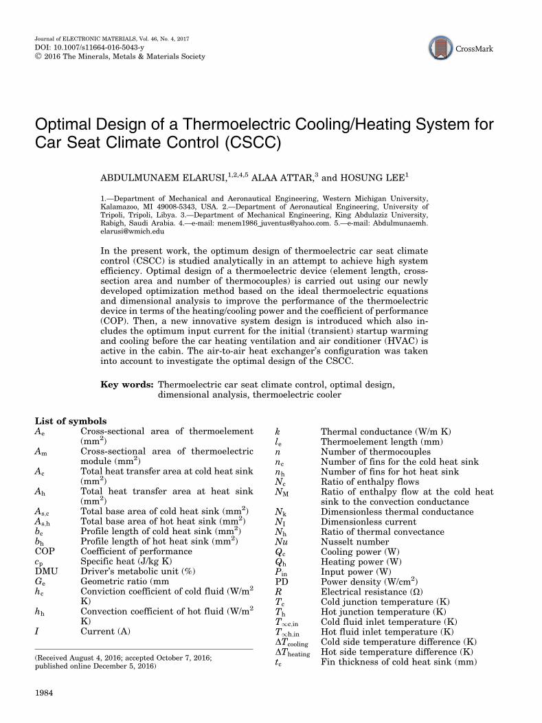
The optimum design theory based on the dimen-sional technique developed by Lee16 is modified andemployed to determine the optimum design of athermoelectric device (TEC) in conjunction with heatsinks (Fig. 2a). From this analysis, it is found that iftwo fluid temperatures at the heat sinks are known,an optimum design always exists and can be deter-mined. This method allows us to optimize theperformance (cooling power and COP) of the TECby simultaneously optimizing the dimensionless cur-rent (NI) and the dimensionless thermal conductance(Nk), which represent the applied current and thegeometric ration (or number of thermocouples),respectively, at a set of given dimensionless param-eters. Such a parameter reduction technique enablesthe six heat balance equations (Eqs. 1–6) to beconverted into two dimensionless equations as seenin Eqs. 7 and 8. This method assumes that the n-typeand p-type thermoelectric elements (Fig. 2b) havethe same leg length and cross-sectional area.
_Qc ¼ _mccp;c T1c;in � T1c;out
� �ð1Þ
_Qc ¼ gchcAcT1c;in þ T1c;out
2� Tc
� �ð2Þ
_Qc ¼ n aTcI �1
2RI2 þ K Tc � Thð Þ
� �ð3Þ
_Qh ¼ n aThI þ1
2RI2 þ K Tc � Thð Þ
� �ð4Þ
_Qh ¼ ghhhAh Th � T1h;in þ T1h;out
2
� �ð5Þ
_Qh ¼ _mhcp;h T1h;out � T1h;in
� �ð6Þ
Fig. 1. Typical thermoelectric cooler module.
Elarusi, Attar, and Lee1986
_Qc and _Qh are the rates of heat absorbed andemitted at the two junctions, respectively, n is thenumber of thermocouples, _mccp;c and _mhcp;h are theenthalpy flows at the cold and the warm heat sinks,respectively, a is the Seebeck coefficient(a ¼ an þ ap), R is the electrical resistivity, and Kis the thermal conductivity (K ¼ Kn þ KpÞ. Thethermal convection conductance is defined asgchcAc which is the inverse of the thermal resistancewhere gc is the total efficiency of the cold heat sink,hc is the convection coefficient and Ac is the totalheat transfer area of the heat sink.
In order to study the optimal design of this system,several dimensionless parameters are introduced. NI,Nk, Nh, Nc, NM, ZT1h;in are defined as the dimension-less current, dimensionless thermal conductance, theratio of the thermal conductance, the ratio of theenthalpy flows, the ratio of the enthalpy flow at thecold heat sink to the convection conductance and thedimensionless figure of merit, respectively.
NI ¼naI
ghhhAhð7Þ
Nk ¼n Ak=L� �
ghhhAhð8Þ
Nh ¼ gchcAc
ghhhAhð9Þ
Nc ¼_mccp;c
_mhcp;hð10Þ
NM ¼ _mccp;c
ghhhAhð11Þ
ZT1h;in ¼ a2
qkT1h;in ð12Þ
The dimensionless temperatures are definedwith respect to the hot fluid inlet temperatureT1h;in as,
T�c ¼ Tc
T1h;inð13Þ
T�h ¼ Th
T1h;inð14Þ
T�1;in ¼ T1c;in
T1h;inð15Þ
Using the dimensionless parameters, Eqs. 1–6 arereduced to two formulas as:
Nh
1þ Nh
2NM
T�1;in�T�
c
� ¼NIT
�c �
N2I
Nh
1
ZT1h;inþNk T�
c �T�h
� �
ð16Þ
1
1þ Nc
2NM
T�h � 1
� �¼NIT
�h �
N2I
2Nk
1
ZT1h;inþNk T�
c �T�h
� �
ð17ÞT�
c and T�h are functions of five independent
parameters.
Fig. 2. (a) Schematic of a TEC with conjunction to heat sinks and (b) a thermoelectric couple.
Optimal Design of a Thermoelectric Cooling/Heating System for Car Seat Climate Control(CSCC)
1987
T�c ¼ f NI;Nk;Nh;T
�1;in;ZT1h;in
� ð18Þ
T�h ¼ f NI;Nk;Nh;T
�1;in;ZT1h;in
� ð19Þ
Then, the dimensionless cooling power Q�c, the
dimensionless heating power Q�h, the dimensionless
input power W�in and the dimensionless COP COP
are formulated as
Q�c ¼ Nh
1 þ Nh
2NM
T�1;in � T�
c
� ð20Þ
Q�h ¼ 1
1 þ Nc
2NM
T�h � 1
� �ð21Þ
P�in ¼ Q�
h �Q�c ð22Þ
COP ¼Q�
c;h
P�in
ð23Þ
Once Eqs. 16 and 17 are solved for the two dimen-sionless temperatures (T�
c andT�h) with initially given
ZT1h;in and T�1;in, NI and Nk can be optimized
simultaneously to give the maximum cooling powerQ�
c and COP from Eqs. 20 and 23, respectively. Thisallows designers to determine the operating condi-tion. In fact, Nk is the geometry or dimension of thethermoelectric device; so, once determined, it ispermanent. But NI represents the current, so it canbe adjusted depending on the demand such astransient initial startup cooling for a short time (afew seconds to minutes) or steady cooling/heating fora longer time (minutes to hours). This dynamicbehavior is usually very difficult to predict withoutthe analysis of dimensionless parameters.
RESULTS AND DISCUSSION
Study of Feher’s VTS
In this section, the VTS heat pump data providedby Feher is reproduced using the ideal thermoelec-tric equation based on Feher’s inputs along withsome needed assumptions for the missing informa-tion. Figure 3 illustrates a schematic of Feher’s air-to-air VTS heat pump design. As seen, the design isconstructed of one TEC clapped between two heatexchangers driven by two auxiliary fans and one airblower. The auxiliary heat exchangers dissipate theheat to the ambient air by the auxiliary fans in acooling mode (Fig. 3a) and absorb heat from ambi-ent air in a heating mode (Fig. 3b). The main heatsink regulates the air (cool or warm) pumped to theseat by the main blower. The geometric dimensionsof this design are given as 209.6 mm in length,92.1 mm in width and 57.2 mm in height. In coolingmode at an ambient temperature (Tamb) of 300.4 K,
the system pumps about 6 cubic feet per minute(cfm) of cold air at a temperature difference of 10 K,which converts to about 33.3 W at an input power of82 W. In the heating mode and at an ambienttemperature of 257.04 K, the VTS pumps at thesame air flow rate at a sensible heating power of56.5 W at a temperature difference of 14.4 K.
In order to meet Feher’s performance data, sev-eral assumptions needed to be considered, some ofwhich are carefully adjusted until a good agreementis observed. For instance, the air flow rate at theauxiliary heat sink is 18 cfm, the heat sinks mate-rials are aluminum, the profile length bf of the heatsinks is 15 mm, the fin thickness tc of the main heatexchanger is 0.7 mm, and the fin thickness of theauxiliary heat sink th is 1 mm. Also, a commercialTEC (TB127-1.4-1.2) was used in the calculationwith the following specifications: module area (Am)is 40 9 40 mm2, the geometric factor is 0.163 cmand the number of thermocouples is 127. Thethermoelectric material properties (a, K , R and Z)were calculated using the effective material prop-erties introduced by Lee et al.17 This technique usesthe maximum parameters which are usually pro-vided by the manufacturer to recalculate the mate-rial properties of the thermoelectric module. Theadvantage of using such material properties lays inreducing the errors associated with the assumptionof neglecting the contact resistances in the idealthermoelectric equations.18 The maximum parame-ters are experimental values, so they alreadyinclude the effects of the thermal and electricalcontact resistances and the Thomson effect.19
Therefore, there is no need to account for theseeffects again in the ideal thermoelectric equations.
Feher’s claims that his VTS heat pump puts outabout 33:3 W of cooling power (Qc) at an input powerof Pin ¼ 82 W, which corresponds to COP ¼ 0:4. Also,the temperature difference across the main heatexchanger (DTcooling) was about 10 K, which can betranslated to a driver’s metabolic unit (DMU) of about26%. To analyze this system, it is assumed that eachheat sink faces a parallel flow with linear tempera-ture gradient, which means that the temperaturebetween fins is the average of the inlet and the exit airtemperatures. The heat exchanger’s parameterswere calculated to match the cooling power andCOP of Feher’s VTS heat pump employing the heatsink equations found in Ref. 13 and Nusselt numbercorrelations found in Ref. 14. Then, the six basicequations were solved for the cooling power and theCOP at variable input current values (I). The pre-dicted results for both the cooling and heating modeswere, finally, compared with Feher’s VTS heat pumpexperimental data as shown in Table I. Figure 4aand b shows a compression between the presentcalculations and Feher’s output data. In Fig. 4a, thepredicted cooling power and COP indicated by thesolid and dashed lines, respectively, show fair agree-ment with the experimental data provided by Feherreferred to by the samples (at an input power of
Elarusi, Attar, and Lee1988

82 W). Similarly, Fig. 4b illustrates the heatingpower and COP versus input power comparedagainst Feher’s heat pump data for the heating modewith good accuracy. The predicted data also show anacceptable agreement with Feher’s data when theflow rate was increased from 6 cfm to 8 cfm, wherethe predicted COP raised, consequently, from 0.4 toabout 0.45 with a small drop in the cooling temper-ature difference from 9.9 K to 7.9 K. Therefore, sincethe validity of this prediction (based on Feher’s heatpump data) is obtained, this paves the way to a newcompression with the optimum design.
Feher’s VTS Optimal Design
The optimization method described above isemployed to find the optimal values for the dimen-sionless parameters (NI,Nk,Q�
c ,Q�h, COP,T�
c , andT�h)
iteratively at a given Nh, T�1;in and ZT1h;in. The same
configuration used to predict Feher’s heat pumpperformance was used in the optimization analysis.Thus, heat sink parameters represented in Nh,thermoelectric material properties (ZT1h;in), and
inlet temperatures (T�1;in) are all inputs taken from
the previous prediction configuration. Then, thedimensionless optimum parameters are convertedback to the real parameter values by using the samedenominator (the thermal resistance, ghhhAh). Thecooling and input powers versus current and ther-moelement geometric ratio are shown in Fig. 5a andb, respectively. Figure 5a was plotted using optimumNk ¼ 0:16, and Fig. 5b was generated using optimumNI ¼ 0:056. From Fig. 4a, it is noticeable that themaximum cooling power occurs when the COP is verysmall and vice versa, so it is important to usemidpoints of the optimal current and thermoelementgeometric ratio that give reasonable cooling powerwithout dropping the COP to unacceptably low levels.
Table II shows a comparison between the presentprediction based on Feher’s heat pump data and theoptimal design results for the cooling mode. It canbe seen that the optimal design has relatively betterperformance (cooling power and COP) over the olddesign. This optimization indicates that if the inputcurrent and the geometric ratio are increased to the
Fig. 3. Schematic diagram of Feher’s VTS heat pump. (a) Cooling mode and (b) heating mode.2
Table I. Comparison between Feher’s VTS heat pump data and the present prediction for cooling andheating modes
Parameter
Cooling mode Heating mode
Feher Prediction Feher Prediction
Tamb Kð Þ 300.4 300.4 257.04 257.04Pin Wð Þ 82 82 82 81.48I Að Þ 6.3 6.3 6.3 6.05Qc=Qh Wð Þ 33.3 33.22 94.6 89.23Tc(K) NA 277.54 NA 255.45Th(K) NA 320.61 NA 322.11DTcooling=DTheating Kð Þ 10 9.91 24.2 27.06COP 0.406 0.406 1.15 1.106DMU ð% ) 26.6 26.5 75.7 71.4PD (W/cm2) 0.18 0.18 0.526 0.496
Inputs: Vc ¼ 6 cfm, Vh ¼ 18 cfm, As;c ¼ 90 � 100 mm2, As;h ¼ 90 � 200 mm2, bc ¼ 10 mm, bh ¼ 20 mm; tc ¼ 0:7 mm, zc ¼ 2:8 mm,nc ¼ 25, hc ¼ 32:78 W/m2 K, hh ¼ 33:172 W/m2 K, gchcAc ¼ 1:854 W/K, ghhhAh ¼ 8:083 W/K, Nh ¼ 0:229, Am ¼ 40 � 40 mm2, n ¼ 127,an ¼ �ap ¼ 210:01l=K, qn ¼ qp ¼ 1:038X cm, kn ¼ kp ¼ 0:016 W/cm K, Z ¼ 2:647 � 10�3 1
K.
Optimal Design of a Thermoelectric Cooling/Heating System for Car Seat Climate Control(CSCC)
1989
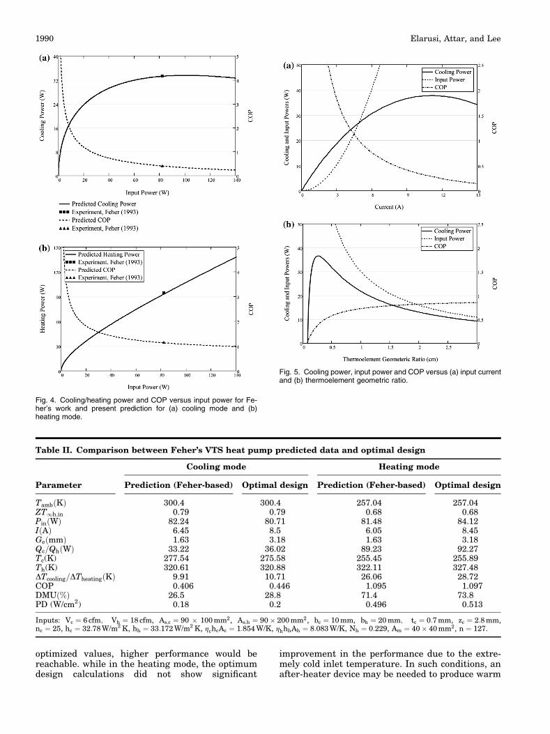
optimized values, higher performance would bereachable. while in the heating mode, the optimumdesign calculations did not show significant
improvement in the performance due to the extre-mely cold inlet temperature. In such conditions, anafter-heater device may be needed to produce warm
Fig. 4. Cooling/heating power and COP versus input power for Fe-her’s work and present prediction for (a) cooling mode and (b)heating mode.
Fig. 5. Cooling power, input power and COP versus (a) input currentand (b) thermoelement geometric ratio.
Table II. Comparison between Feher’s VTS heat pump predicted data and optimal design
Cooling mode Heating mode
Parameter Prediction (Feher-based) Optimal design Prediction (Feher-based) Optimal design
Tamb Kð Þ 300.4 300.4 257.04 257.04ZT1h;in 0.79 0.79 0.68 0.68Pin Wð Þ 82.24 80.71 81.48 84.12I Að Þ 6.45 8.5 6.05 8.45Ge mmð Þ 1.63 3.18 1.63 3.18Qc=Qh Wð Þ 33.22 36.02 89.23 92.27Tc(K) 277.54 275.58 255.45 255.89Th(K) 320.61 320.88 322.11 327.48DTcooling=DTheating Kð Þ 9.91 10.71 26.06 28.72COP 0.406 0.446 1.095 1.097DMU %ð Þ 26.5 28.8 71.4 73.8PD (W/cm2) 0.18 0.2 0.496 0.513
Inputs: Vc ¼ 6 cfm; Vh ¼ 18 cfm, As;c ¼ 90 � 100 mm2, As;h ¼ 90 � 200 mm2, bc ¼ 10 mm, bh ¼ 20 mm; tc ¼ 0:7 mm, zc ¼ 2:8 mm,nc ¼ 25, hc ¼ 32:78 W/m2 K, hh ¼ 33:172 W/m2 K, gchcAc ¼ 1:854 W/K, ghhhAh ¼ 8:083 W/K, Nh ¼ 0:229, Am ¼ 40 � 40 mm2, n ¼ 127.
Elarusi, Attar, and Lee1990

air to the seat sooner until the interior air temper-ature rises up resulting in higher COP. However,TECs are considerably more efficient in the heatingmode than the cooling mode because the joule
heating term (RI2) is additive in the heating mode.Figure 6 shows the change of the cooling/heating
power, temperature difference and COP versus theinput current at various ambient temperatures forcooling and heating modes. It is clear that as theambient temperature rises, both the cooling/heating
power and the temperature difference will increasefurther (Fig. 6a, b, c, and d) resulting in higherCOPs (Fig. 6e and f). This is actually an advantagein the cooling mode since the cooling power will dropas the interior of the vehicle temperature cools downresponding to opening the windows or activating theHVAC. However, it is a disadvantage in the heatingmode because as the interior of the vehicle warmsdue to the engine heat, lower heating from the seatwould be desirable.
Fig. 6. Cooling/heating power, temperature difference and COP versus input current at varoius ambient temperatures. (a) Cooling power versusinput current, (b) heating power versus input current, (c) cooling temperature difference versus input current, (d) heating temperature differenceversus input current, (e) cooling COP versus input current and (f) heating COP versus input current.
Optimal Design of a Thermoelectric Cooling/Heating System for Car Seat Climate Control(CSCC)
1991

New Design of a CSCC
In the new design, two thermoelectric heat pumpsare used, one of which is installed in the backrestand the other in the seat rest as seen in Fig. 7a. Thetotal conditioned air flow rate of the old design isdivided by two, so that each thermoelectric heatpump provides about 3 cfm of conditioned air with atotal flow rate of 6 cfm for the whole seat. Also, theoptimal design of the new system was built based onthe same input power used by Feher, but the basearea of the heat exchangers was decreased with arelatively higher profile length to meet the olddesign performance. Several key factors were con-sidered when designing the new CSCC:
1. Limited space within the vehicle seat. The newCSCC can be easily installed and fit even verythin vehicle seats.
2. Mounting the new CSCC heat pumps close tothe seat surface can guarantee efficient deliveryof the conditioned air to the occupant.
3. Also, short and simplified air ducting would beused, which reduces the air duct heat leak, costand pressure drop which results in reducing thenoise and fans input power.
Figure 7b and c indicates the cooling and the heatingmodes, respectively. As seen from this drawing, theTEC is sandwiched between the cold and hot heatsinks. The heat sinks are optimized in terms of thefin spacing and fin thickness to minimize the thermalresistances (gchcAc and ghhhAh) and, thus, to max-imize the heat transfer rates. The flow rates in theheat sinks are regarded as channel flows, so theNusselt number correlations found in Ref. 15 areused to calculate the convection coefficients. Finally,the same optimal design method is applied to find theoptimum combination of the dimensionless parame-ters (NI;Nk) as shown in Fig. 8a and b. Similarly,these dimensionless parameters can be converted tothe real parameters (thermoelement geometric ratio,number of thermocouples and input current) fromthe definition of these dimensionless quantities andby using the same thermal conductance ghhhAh.Usually the number of thermocouples is fixed andthe thermoelement geometric ratio is optimized togive the maximum cooling/heating power. Then,using the same number of thermocouples, the opti-mum input current can be determined by theequivalent procedure.
Fig. 7. Schematic of the new CSCC design. (a) The air flow venting system, (b) cooling mode and (c) heating mode.
Elarusi, Attar, and Lee1992

The newly designed CSCC heat pump results areshown in Table III. The goal of the new design is toprovide occupant comfort not only during the steady
state but also during the startup (transient) perioduntil the cars HVAC system is active. Therefore, thetransient operation behavior is equivalently impor-tant, which is also studied and its results are shown inTable III. The column title ‘maximum power’ for thecooling mode in Table III means that if the current isincreased above that value, there will not be muchgain in the cooling power. For instance, an increasedpower consumption of 66.75 W leads to slight gains inthe cooling power and temperature difference of0.25 W and 0.148 K, respectively. However, for heat-ing, the scenario is different. We can increase theheating power from 47.91 W to 83 W and temperaturedifferences from 28.806 K to 49.91 K with the currentincreases from 4.2 A to 6 A which results in increasingthe electrical power consumption from 40.57 W to85.67 W. This may be incorporated as an option intocar seat climate control for extreme winter conditionsif the car battery is permitted.
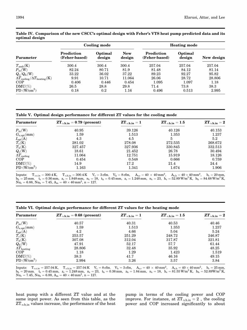
Note that the results shown in Table III are foronly one thermoelectric heat pump (backrest orseatrest). Thus, to obtain the whole seat perfor-mance, the cooling/heating power, input power andDMU should be multiplied by two. The new designperformance for the whole seat is compared with theold design performance (based on Feher’s data) andwith the optimal design of the VTS heat pump asshown in Table IV. This comparison indicates thatthe new optimal design of the CSCC system has theadvantage over the two other designs in terms of theperformance with significant size reduction from200 mm 9 90 mm 9 50 mm to approximately40 mm 9 40 mm 9 52 mm for each heat pump.
Furthermore, this dimensionless technique candetermine the optimal parameters for the differentdimensionless figure of merit (ZT) values. It is foundthat as the ZT value changes, the optimal designparameters (optimal geometric ratio and inputcurrent) will accordingly change. Table V indicatesthe cooling mode performance of the air-to-air VTS
Fig. 8. Cooling power, input power and COP versus (a) dimension-less input current and (b) and dimensionless thermal conductance.
Table III. Summary of the new CSCC’s optimal design
Parameter
Cooling mode Heating mode
Max. power(transient)Iopt ¼ 4:3A
Min. power(steady state)Iopt ¼ 1:5A
Max. power(transient)Iopt ¼ 4:2A
Min. power(steady state)Iopt ¼ 0:5A
Tamb Kð Þ 300.4 294 257.04 294ZT1h;in 0.79 0.772 0.68 0.772Pin Wð Þ 40.95 5.04 40.57 0.567Qc=Qh Wð Þ 18.61 9.74 47.91 4.17DTcooling=DTheating Kð Þ 11.064 5.792 28.806 2.507COP 0.454 1.93 1.18 7.35DMU %ð Þ 14.9 7.8 38.3 3.3PD (W/cm2) 1.163 0.609 2.994 0.261
Inputs: Vc ¼ 3 cfm; Vh ¼ 8 cfm, As;c ¼ 40 � 40 mm2, As;h ¼ 40 � 40 mm2, bc ¼ 20 mm, bh ¼ 25 mm; tc ¼ 0:36 mm, zc ¼ 1:848 mm,nc ¼ 18, th ¼ 0:45 mm, zc ¼ 1:248 mm, nc ¼ 23, hc ¼ 52:89 W/m2 K, hh ¼ 84:68 W/m2 K, Nuc ¼ 6:88, Nuh ¼ 7:45, Am ¼ 40 � 40 mm2,Ge ¼ 1:59 mm, n ¼ 127.
Optimal Design of a Thermoelectric Cooling/Heating System for Car Seat Climate Control(CSCC)
1993
heat pump with a different ZT value and at thesame input power. As seen from this table, as theZT1h;in values increase, the performance of the heat
pump in terms of the cooling power and COPimprove. For instance, at ZT1h;in ¼ 2 , the coolingpower and COP increased significantly to about
Table V. Optimal design performance for different ZT values for the cooling mode
Parameter ZT1h;in ¼ 0:79 (present) ZT1h;in ¼ 1 ZT1h;in ¼ 1:5 ZT1h;in ¼ 2
Pin Wð Þ 40.95 39.126 40.126 40.153Ge;opt mmð Þ 1.59 1.513 1.353 1.237Iopt Að Þ 4.3 4.5 5 5.2Tc Kð Þ 281.02 278.08 272.535 268.672Th Kð Þ 327.457 327.936 330.845 332.513Qc Wð Þ 18.61 21.452 26.78 30.494DTcooling 11.064 12.751 15.919 18.126COP 0.454 0.548 0.666 0.759DMU %ð Þ 14.9 17.2 21.4 24.4PD (W/cm2) 1.163 1.341 1.674 1.906
Inputs: T1c;in ¼ 300:4 K, T1h;in ¼ 300:4 K Vc ¼ 3 cfm; Vh ¼ 8 cfm, As;c ¼ 40 � 40 mm2, As;h ¼ 40 � 40 mm2, bc ¼ 20 mm,bh ¼ 25 mm; tc ¼ 0:36 mm, zc ¼ 1:848 mm, nc ¼ 18, th ¼ 0:45 mm, zc ¼ 1:248 mm, nc ¼ 23, hc ¼ 52:89 W/m2 K, hh ¼ 84:68 W/m2 K,Nuc ¼ 6:88, Nuh ¼ 7:45, Am ¼ 40 � 40 mm2, n ¼ 127.
Table VI. Optimal design performance for different ZT values for the heating mode
Parameter ZT1h;in ¼ 0:68 (present) ZT1h;in ¼ 1 ZT1h;in ¼ 1:5 ZT1h;in ¼ 2
Pin Wð Þ 40.57 40.31 40.53 40.46Ge;opt mmð Þ 1.59 1.513 1.353 1.237Iopt Að Þ 4.2 4.66 5.04 5.24Tc Kð Þ 253.57 251.29 248.72 246.87Th Kð Þ 307.08 312.04 317.87 321.81Qh Wð Þ 47.91 52.17 57.7 61.44DTheating 28.806 32.48 35.92 48.25COP 1.18 1.29 1.423 1.519DMU %ð Þ 38.3 41.7 46.16 49.15PD (W/cm2) 2.994 3.26 3.57 3.84
Inputs: T1c;in ¼ 257:04 K, T1h;in ¼ 257:04 K Vc ¼ 8 cfm; Vh ¼ 3 cfm, As;c ¼ 40 � 40 mm2, As;h ¼ 40 � 40 mm2, bc ¼ 25 mm,bh ¼ 20 mm; tc ¼ 0:45 mm, zc ¼ 1:248 mm, nc ¼ 23, th ¼ 0:36 mm, zh ¼ 1:84 mm, nc ¼ 18, hc ¼ 81:55 W/m2 K, hh ¼ 52:89W/m2 K,Nuc ¼ 7:45, Nuh ¼ 6:88, Am ¼ 40 � 40 mm2, n ¼ 127.
Table IV. Comparison of the new CSCC’s optimal design with Feher’s VTS heat pump predicted data and itsoptimal design
Parameter
Cooling mode Heating mode
Prediction(Feher-based)
Optimaldesign
Newdesign
Prediction(Feher-based)
Optimaldesign New design
Tamb Kð Þ 300.4 300.4 300.4 257.04 257.04 257.04Pin Wð Þ 82.24 80.71 81.9 81.48 84.12 81.14Qc=Qh Wð Þ 33.22 36.02 37.22 89.23 92.27 95.82DTcooling=DTheating Kð Þ 9.91 10.71 11.064 26.06 28.72 28.806COP 0.406 0.446 0.454 1.095 1.097 1.18DMU %ð Þ 26.5 28.8 29.8 71.4 73.8 38.3PD (W/cm2) 0.18 0.2 1.16 0.496 0.513 2.995
Elarusi, Attar, and Lee1994

30.494 W and 0.759 W, respectively, compared tothe present work (ZT1h;in ¼ 0:79).
Similarly, the thermoelectric heat pump perfor-mance showed significant improvement in the heat-ing mode as the figure of merit values increased, asseen in Table VI. In other words, the power con-sumption can be significantly reduced with equiva-lent heating levels. For instance, at ZT ¼ 2, theCSCC can provide heating power and air tempera-ture differences similar to the present design (47 Wand 28�C, respectively) at an input power of 30.5 W.These results shows a remarkable gain in the powerconsumption by roughly 25%. Such high perfor-mance indicates that if new materials with higherZT values are designed or discovered in the future,the thermoelectric CSCC can be very competitivewith other climate control systems in the automo-tive industry. Moreover, this also can help futuredesigners of temperature-controlled seats by pro-viding a clear vision for the performance of futuredesigns.
CONCLUSION
The presented work investigates the optimaldesign of thermoelectric cooler applied in a car seatclimate control (CSCC). This optimization utilizes anewly developed optimization theory with thedimensional technique to simultaneously obtainthe optimum combination of the dimensionlessapplied current NI and the dimensionless thermalconductance Nk to determine the optimum cooling/heating power and COPs suitable for a tempera-ture-controlled seat. The optimal design of Feher’sheat pump design was analyzed analytically main-taining the same input parameters and overallgeometry, where the optimized results indicatedan increase in the COP by about 10% in the coolingmode compared with Feher’s design.
Then, a new thermoelectric CSCC design whichcomprised of two heat pumps installed at thebackrest and the seatrest was presented. The newdesign also provides the optimum input currentvalues for the transient (short-term) and steady-state (long-term) operating conditions. With signif-icant size reduction and a very slight increase in the
overall height, the optimized results of the newdesign showed comparable performance to Feher’sheat pump data and its optimum design. Such anapproach may provide the temperature-controlledseat designers with a guideline that helps move thisfeature from being optional to becoming standardvehicle equipment.
REFERENCES
1. L.E. Alkire and W.H. Carter, US Patent 1439681 A, 26 Dec1922.
2. L.H. Johnson, US Patent 3127931 A, 4 May 1964.3. J. Lustbader, Evaluation of Advanced Automotive Seats to
Improve Thermal Comfort and Fuel Economy, SAE Tech-nical Paper 2005-01-2056 (2005). doi:10.4271/2005-01-2056.
4. S. Feher, Thermoelectric Air Conditioned Variable Tem-perature Seat (VTS) and Effect Upon Vehicle OccupantComfort, Vehicle Energy Efficiency, and Vehicle Environ-mental Compatibility, SAE Technical Paper 931111 (1993).doi:10.4271/931111.
5. D.F. Gallup, D.R. Noles, and R.R. Willis, US Patent, 3 Jun2003.
6. M. Menon and H.H. Asada, in 2006 American ControlConference, (2006).
7. H.S. Choi, S. Yun, and K.I. Whang, Appl. Therm. Eng. 27,2841 (2007).
8. M. Vinoth and D. Prema, in 2014 International Conferenceon Computation of Power, Energy, Information and Com-munication (ICCPEIC), vol. 488 (2014).
9. H. Du, Y.P. Wang, X.H. Yuan, Y.D. Deng, and C.Q. Su, J.Electron. Mater. 44, 2203 (2014).
10. A. Attar, H. Lee, and S. Weera, J. Electron. Mater. 43, 2179(2014).
11. A. Attar and H. Lee, Energy Convers. Manag. 112, 328(2016).
12. A. Attar, H. Lee, and S. Weera, J. Electron. Mater. 44, 2177(2015).
13. H. Lee, Thermal Design: Heat Sinks, Thermoelectrics, HeatPipes, Compact Heat Exchaners, and Solar Cells (NewJersey: Wiley, 2010).
14. P. Teertstra, M.M. Yovanovich, and J.R. Culham, in Fif-teenth Annual IEEE Semiconductor Thermal Measurementand Management Symposium (1999). doi:10.1109/STHERM.1999.762426.
15. W. Zhimin and C.K. Fah, in Proceedings of the 1stElectronic Pachaging Technology Confernece (1997).doi:10.1109/EPTC.1997.723898.
16. H. Lee, Appl. Energy 106, 79 (2013).17. H. Lee, A. Attar, and S.L. Weera, J. Electron. Mater. 44,
2157 (2015).18. A. Elarusi, H. Fagehi, H. Lee, and A. Attar, J. Electron.
Mater. (2016). doi:10.1007/s11664-016-4948-9.19. H. Lee, Energy 56, 61 (2016).
Optimal Design of a Thermoelectric Cooling/Heating System for Car Seat Climate Control(CSCC)
1995