optimal design and operation of a steel plant integrated with a polygeneration system
TRANSCRIPT

PROCESS SYSTEMS ENGINEERING
Optimal Design and Operation of a Steel Plant Integrated witha Polygeneration System
Hamid GhanbariThermal and Flow Engineering Laboratory, Chemical Engineering Department, Abo Akademi University,
Abo 20500 Finland
Center for Advanced Process Decision-making, Chemical Engineering Department, Carnegie Mellon University,Pittsburgh, PA 15213
Henrik Sax�enThermal and Flow Engineering Laboratory, Chemical Engineering Department, Abo Akademi University,
Abo 20500 Finland
Ignacio E. GrossmannCenter for Advanced Process Decision-making, Chemical Engineering Department, Carnegie Mellon University,
Pittsburgh, PA 15213
DOI 10.1002/aic.14098Published online April 19, 2013 in Wiley Online Library (wileyonlinelibrary.com)
A process integration approach has been applied to integrate a traditional steelmaking plant with a polygeneration sys-tem to increase energy efficiency and suppress carbon dioxide emissions from the system. Using short-cut models andempirical equations for different units and available technologies for gas separation, methane gasification, and methanolsynthesis, a mixed integer nonlinear model is applied to find the optimal design of the polygeneration plant and opera-tional conditions of the system. Due to the complexity of the blast furnace (BF) operation, a surrogate model techniqueis chosen based on an existing BF model. The results show that from an economic perspective, the pressure swingadsorption process with gas-phase methanol unit is preferred. The results demonstrate that integration of conventionalsteelmaking with a polygeneration system could decrease the specific emissions by more than 20 percent. VC 2013 Amer-
ican Institute of Chemical Engineers AIChE J, 59: 3659–3670, 2013
Keywords: process integration, polygeneration system, carbon dioxide emission, steelmaking, generalized disjunctiveprogramming
Introduction
Traditional steelmaking is known as an energy intensivesector and a remarkable source of carbon dioxide emissionsamong primary industries. Improvement of the energy effi-ciency could increase the economic profitability and reduceenvironmental impact. In recent years, steel plants haveexperienced increasing expenses related to environmentalissues, such as increase in carbon dioxide emission taxes.Parallel to this, the current financial crisis has made steel-makers face lower demand and falling prices, which havechanged their business priorities to focus on lower operationcosts, securing capital, and sustaining client relationship.These effects are more visible in steel companies in devel-oped countries in comparison with major steel producers inthe world, such as China and India.
Steelmaking processes are well-established and have alreadyevolved to a mature state. It is, therefore, difficult to substan-tially reduce their energy demand and the emissions. A potentialis still provided by an integration of steel plants with chemicalplants, including carbon capturing and sequestration (CCS) anda polygeneration system. Due to tight integration of the powergeneration and the chemical synthesis sections, polygenerationsystems have higher overall energy efficiency compared tostand-alone plants producing the same products.1,2 Also thechemical products produced by a polygeneration plant can beused to substitute traditional liquid fuels, which is expected toresults in cost-effective solutions for implementation of carbondioxide capture and sequestration units.
Large amount of off-gases from the coke oven, blast fur-nace (BF), and basic oxygen furnace (BOF) are produced intraditional steelmaking. Today, these residual gases are usedfor heating (e.g., of steel slabs and preheating of combustionair) and in combined heat and power (CHP) plants. Zhanget al.2 proposed a gas polygeneration strategy integrated withprimary steelmaking to tackle the problem of energy effi-ciency and polluting emissions. The idea is to remove carbon
Additional Supporting Information may be found in the online version of thisarticle.
Correspondence concerning this article should be addressed to H. Ghanbari [email protected].
VC 2013 American Institute of Chemical Engineers
AIChE Journal 3659October 2013 Vol. 59, No. 10

dioxide and use the residual gases as feedstock to a polygen-eration system to produce district heat, electricity, and meth-anol as byproducts.
There have been several studies on optimal design ofpolygeneration systems. Liu et al.1,3,4 studied a system withdifferent feed-stocks and technologies that coproduces elec-tricity and methanol. Their study showed that the conversionrate of technologies, the price of feedstock, the capital invest-ment, and the fixed operating cost have strong influence on thenet present value (NPV). They also presented a multiobjectivemixed-integer nonlinear programming formulation of a typicalpolygeneration process operating over a time horizon whereboth profitability and environmental impacts were considered.
Chen et al.5,6 proposed a coal and biomass-based polygen-eration system to produce power, liquid fuels, and chemicalsunder different economic scenarios using nonlinear program-ming. They also performed a simultaneous optimization, ana-lyzing the design and the operational decision variables. Theresults showed that higher NPVs can be obtained withincreasing operational flexibility.
Ghanbari et al.7,8 studied the possibilities to suppress car-bon dioxide emissions and to increase the energy efficiencyof an integrated steel plant under different scenarios of car-bon dioxide emission and sequestration costs, different BFtechnologies and alternative fuels. Nonlinear programmingwas applied to tackle the optimization problem, particularlyfocusing on the performance of the BF operation as the coreof the system. The potential of partially replacing coke withdifferent fuels, such as oil, natural gas, and biomass simulta-neously applying different technologies of BF operation (topgas recycling, cold oxygen injection, and massive hot blastoxygen enrichment) was investigated in a steel plant
integrated with a polygeneration system. The results indi-cated a strong potential of combining process integrationwith the implementation of new BF technologies; it wasfound that the carbon dioxide emissions could be reduced bymore than 50% in comparison with conventionalsteelmaking.
In the study of this article, a superstructure with commonpossible technologies for gas separation, methane gasification(MG), and methanol production (MP) has been proposed withthe aim to investigate the optimal design and operation of thewhole integrated steel and polygeneration system. Shortcut mod-els and empirical equations based on a Finnish steel plant areused for some of the unit processes. Due to the complexity ofthe BF operation, a surrogate model based on partial least-square regression, and the Kriging method was developed tosimulate the performance of the furnace in the system. Themain difference between the suggested system of this study anda stand-alone polygeneration lies in the composition of the feed-stock which is reliant on the operational state of the steel plant.
Process and Model Description
Figure 1 presents a conventional primary steelmakingplant integrated with a polygeneration system and a carboncapturing plant. It includes a coke plant (CP), sinter plant(SP), BF, BOF, hot stoves for blast preheating and units forCCS, MG, MP, and CHP generation. A superstructure withall possible network configurations for the MG, MP, andCCS units is presented in the next section. The system com-prises primary steelmaking from sintermaking and cokemak-ing through the BF up to liquid steel, so the process unitsfor casting and rolling are not included in this study. In all
Figure 1. Integrated primary steelmaking with suggested polygeneration plant superstructure.
PSA: pressure swing adsorption, MEM: membrane adsorption, SMR: steam methane reforming, POR: partial oxidation reforming,
CDR: carbon dioxide reforming, WSP: water separation, LPMEOH: liquid-phase methanol unit, GPMEOH: gas-phase methanol unit,
GSP: gas separation unit, DME: dimethyl ether purification unit, MEOH: methanol purification unit, TSA: temperature swing adsorp-
tion, COPURE: chemical absorption unit, WGS: water gas shift unit, CCA: CO2 chemical absorption, CCM: CO2 capturing mem-
brane, C1–C7: compressors, HM: hot metal, COG: coke oven gas, BFG: blast furnace gas, BOFG: basic oxygen furnace gas, CP: coke
plant, SP: sinter plant, BF: blast furnace, BOF: basic oxygen furnace, HS: hot stoves, CHP: combined heat and power plant.
3660 DOI 10.1002/aic Published on behalf of the AIChE October 2013 Vol. 59, No. 10 AIChE Journal

figures to follow, the main streams and unit processes areshown. The aim of the study is to find a compromise betweeneconomic (investment and operation cost) and environmental(specific carbon dioxide emission) aspects of the system.
Coke plant
Coke is still the main source of thermal energy and reductantin the BF operation. The cokemaking process involves carbon-ization of coal at high temperatures in the absence of air, wherea series of physical and chemical changes take place with theevolution of gases and vapors, finally creating a solid lumpy re-sidual, coke. Cokemaking products are coke, coke oven gas(COG), tar, and residual fuel oil. The main part of the coke goesto the BF, while a smaller amount of coke breeze goes to theSP. For practical reasons, the capacity of the coke production inthe present study was considered to be fixed at an upper limit(55 t/h), so any deficit/excess of coke (after the requirement ofthe SP and BF) will be bought/sold. The conversion of coal tometallurgical coke in the CP is simply modeled by linear rela-tions between the feed rate of coal and the flow rates of pro-duced coke and COG.9 The dry composition of COG is assumedto be constant and it contains carbon monoxide, carbon dioxide,hydrogen, nitrogen, oxygen, and methane. Due to a high amountof hydrogen and methane in the gas, the stream is considered asfeedstock to a gasification unit and to CHP units in the polygen-eration system to produce electricity and district heat.
Sinter plant
The sintering process is a pretreatment step in the produc-tion of iron, where fine particles of iron ore are agglomer-ated by partial melting to yield a strong lumpy burdenmaterial suitable as a feed in the BF. Agglomeration of thefines is necessary to enable the passage of hot gases and pre-vent fluidization during the subsequent BF operation. Cokefeed rate, iron ore feed rate, and limestone feed rate wereconsidered as main inputs to the SP unit and sinter andrecovered heat as main products.9 In the steelmaking plantstudied in this article, the sintermaking capacity was limited,so external iron bearing materials may be needed to reachthe desired steel production rate. In such cases, pellets froman external producer are used in the system in the range of0–600 kg/thm (i.e., kilogram per ton of hot metal).
Blast furnace
The BF as the heart of the steel plant acts as a large shaft-like countercurrent heat exchanger and chemical reactor,where the agglomerated iron bearing burden is charged withcoke in alternate layers. The combustion of coke, which ismaintained by the supply of preheated air (blast), providesCO to reduce iron oxides to iron and provides energy to heatand melt the iron and impurities. As the main product, liquidmetal, often referred to as hot metal, is obtained, which canbe further refined to steel in the BOF (see below). Due tothe complexity of the BF, a first-principles model9 was usedto generate a surrogate model based on partial least-squares10
and Kriging11 techniques. A data set of 5000 feasible stateswas generated by the original model, and autoscale prepro-cessing with contiguous block cross validation was appliedto build and evaluate the surrogate model, expressed as
ZBFm 5A1;m1
X5
n51A2;m;nX BF
n (1)
where A1,m and A2;m;n are regression coefficients,XBF
n nð 5 1, … 5) stands for hot metal production rate,
specific oil rate, pellet rate, blast oxygen content, and blasttemperature, which are the five inputs to the BF model. The15 outputs ZBF
m mð 5 1, …, 15) in the surrogate model arethe specific coke rate, volume flow rate of top gases, compo-sition of top gases H2;N2;CO 2;COð Þ, top gas temperature,sinter flow rate, blast volume flow rate, (raceway) flame tem-perature, burden residence time, bosh gas volume, limestonefeed flow rate, quartz feed flow rate, and slag flow rate9
(Table 2). For the last three terms, the determination coeffi-cients based on the partial least-squares algorithm was foundinsufficient. Hence, the Kriging algorithm was used based onpolynomials of order zero and Gaussian correlation. Theresulting surrogate model is expressed as
ZBF
m 5lm1Y
s
csj exp 2hmnd 2ns
� �(2)
where lm is the generalized least-squares estimate for thepolynomial term, hmn is the correlation function parameters,d2
ns5 XBFn 2wsn
� �are the differences between a point and the
design sites wsn, and s is the number of random points (here,s 5 49) that have been generated by the Latin hypercubemethod.11
Basic oxygen furnace
In the BOF, a mixture of hot metal, scrap, and limestoneis charged into the refractory-lined steelmaking furnace andthen oxygen is injected into the molten mixture at supersonicspeed, resulting in oxidation of carbon and impurities, pro-ducing liquid crude steel (ls) with typically 0.1–0.5 wt % ofcarbon, and steelmaking slag. A general mass balance isused based on known hot metal flow, considering constantcomposition of top gases (mainly CO and CO2) and that50% of them can be recovered. For the sake of simplicity,the feed of scrap was assumed to be one fourth of the massof hot metal in the feed.9
Carbon capturing and sequestration
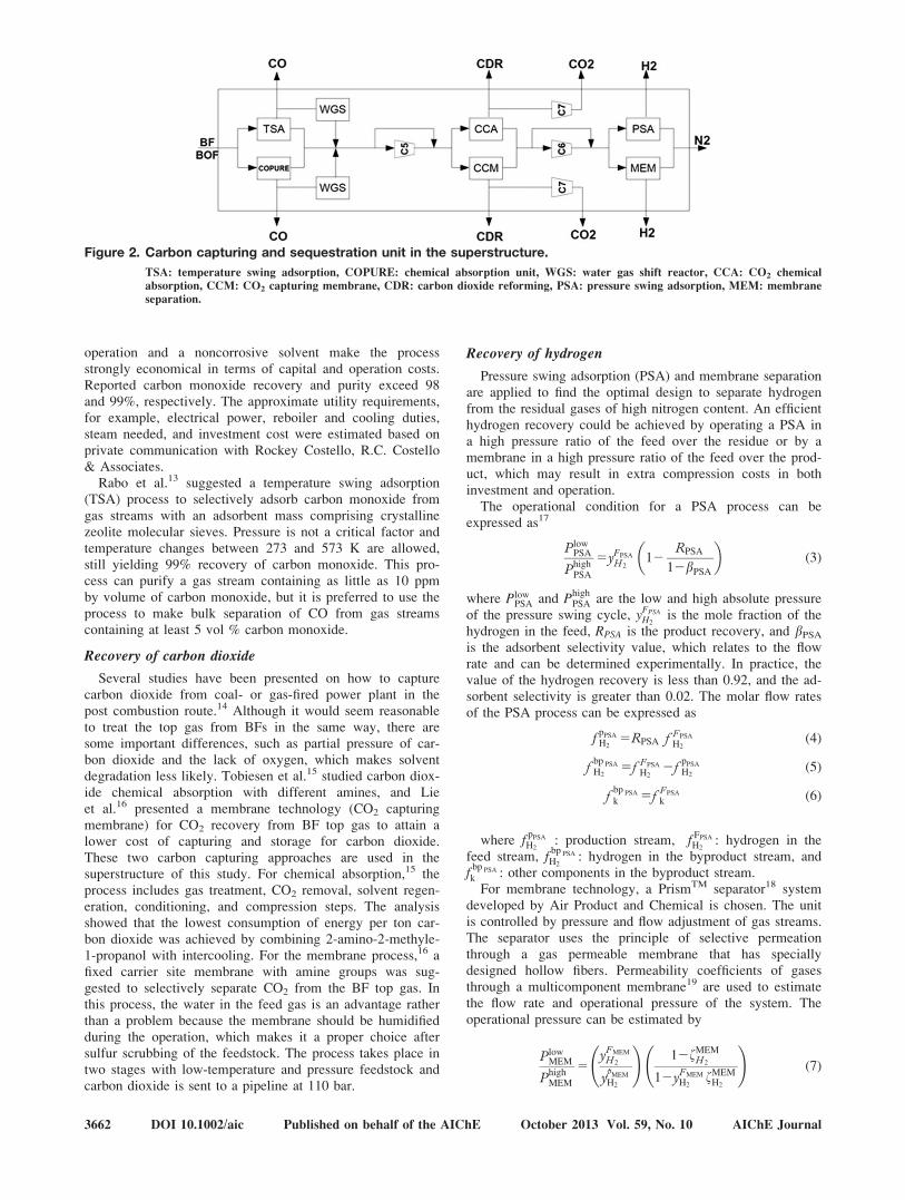
An integration of a carbon dioxide capturing unit with apolygeneration system could be a long-term solution for sup-pressing CO2 emissions from steel plants. BF top gas con-tains more than 20 vol % of carbon monoxide, which couldbe used to produce high-value chemical byproducts, such asmethanol. It also contains more than 20 vol % carbon diox-ide which could be captured and sequestrated; therefore, it ispossible to suppress emissions from a conventional steelplant by exporting carbon from the system in the form ofbyproducts.7,8 Figure 2 shows the unit processes for a CCSplant for gases from the BF and BOF. Three major unitswith two different CO, CO2, and H2 separation technologiesare included in the study to find the optimal design for theCCS plant.
Recovery of carbon monoxide
To recover the carbon monoxide from gas streams, themost common methods used are liquefaction, chemicalabsorption, and selective adsorption. Liquefaction is not suit-able in the present application due to relatively high nitrogenconcentration in the BF top gas, because CO and N2 arevery similar in nature, which makes their separation by phys-ical means difficult. For chemical absorption, the COPureSM
process12 can be used to selectively separate carbon monox-ide from the BF top gas. Low-pressure and temperature
AIChE Journal October 2013 Vol. 59, No. 10 Published on behalf of the AIChE DOI 10.1002/aic 3661
operation and a noncorrosive solvent make the processstrongly economical in terms of capital and operation costs.Reported carbon monoxide recovery and purity exceed 98and 99%, respectively. The approximate utility requirements,for example, electrical power, reboiler and cooling duties,steam needed, and investment cost were estimated based onprivate communication with Rockey Costello, R.C. Costello& Associates.
Rabo et al.13 suggested a temperature swing adsorption(TSA) process to selectively adsorb carbon monoxide fromgas streams with an adsorbent mass comprising crystallinezeolite molecular sieves. Pressure is not a critical factor andtemperature changes between 273 and 573 K are allowed,still yielding 99% recovery of carbon monoxide. This pro-cess can purify a gas stream containing as little as 10 ppmby volume of carbon monoxide, but it is preferred to use theprocess to make bulk separation of CO from gas streamscontaining at least 5 vol % carbon monoxide.
Recovery of carbon dioxide
Several studies have been presented on how to capturecarbon dioxide from coal- or gas-fired power plant in thepost combustion route.14 Although it would seem reasonableto treat the top gas from BFs in the same way, there aresome important differences, such as partial pressure of car-bon dioxide and the lack of oxygen, which makes solventdegradation less likely. Tobiesen et al.15 studied carbon diox-ide chemical absorption with different amines, and Lieet al.16 presented a membrane technology (CO2 capturingmembrane) for CO2 recovery from BF top gas to attain alower cost of capturing and storage for carbon dioxide.These two carbon capturing approaches are used in thesuperstructure of this study. For chemical absorption,15 theprocess includes gas treatment, CO2 removal, solvent regen-eration, conditioning, and compression steps. The analysisshowed that the lowest consumption of energy per ton car-bon dioxide was achieved by combining 2-amino-2-methyle-1-propanol with intercooling. For the membrane process,16 afixed carrier site membrane with amine groups was sug-gested to selectively separate CO2 from the BF top gas. Inthis process, the water in the feed gas is an advantage ratherthan a problem because the membrane should be humidifiedduring the operation, which makes it a proper choice aftersulfur scrubbing of the feedstock. The process takes place intwo stages with low-temperature and pressure feedstock andcarbon dioxide is sent to a pipeline at 110 bar.
Recovery of hydrogen
Pressure swing adsorption (PSA) and membrane separationare applied to find the optimal design to separate hydrogenfrom the residual gases of high nitrogen content. An efficienthydrogen recovery could be achieved by operating a PSA ina high pressure ratio of the feed over the residue or by amembrane in a high pressure ratio of the feed over the prod-uct, which may result in extra compression costs in bothinvestment and operation.
The operational condition for a PSA process can beexpressed as17
P lowPSA
PhighPSA
5yFPSA
H 212
RPSA
12bPSA
� �(3)
where PlowPSA and Phigh
PSA are the low and high absolute pressureof the pressure swing cycle, yFPSA
H2is the mole fraction of the
hydrogen in the feed, RPSA is the product recovery, and bPSA
is the adsorbent selectivity value, which relates to the flowrate and can be determined experimentally. In practice, thevalue of the hydrogen recovery is less than 0.92, and the ad-sorbent selectivity is greater than 0.02. The molar flow ratesof the PSA process can be expressed as
fpPSA
H25RPSA f FPSA
H2(4)
fbp PSA
H25f FPSA
H22f
pPSA
H2(5)
fbp PSA
k 5f FPSA
k (6)
where fpPSA
H2: production stream, f FPSA
H2: hydrogen in the
feed stream, fbp PSA
H2: hydrogen in the byproduct stream, and
fbp PSA
k : other components in the byproduct stream.For membrane technology, a PrismTM separator18 system
developed by Air Product and Chemical is chosen. The unitis controlled by pressure and flow adjustment of gas streams.The separator uses the principle of selective permeationthrough a gas permeable membrane that has speciallydesigned hollow fibers. Permeability coefficients of gasesthrough a multicomponent membrane19 are used to estimatethe flow rate and operational pressure of the system. Theoperational pressure can be estimated by
P lowMEM
PhighMEM
5yFMEM
H 2
ypMEM
H2
!12fMEM
H 2
12yFMEM
H2fMEM
H2
!(7)
Figure 2. Carbon capturing and sequestration unit in the superstructure.
TSA: temperature swing adsorption, COPURE: chemical absorption unit, WGS: water gas shift reactor, CCA: CO2 chemical
absorption, CCM: CO2 capturing membrane, CDR: carbon dioxide reforming, PSA: pressure swing adsorption, MEM: membrane
separation.
3662 DOI 10.1002/aic Published on behalf of the AIChE October 2013 Vol. 59, No. 10 AIChE Journal

where PlowMEM and Phigh
MEM are the product and feed streampressures, yFMEM
H2and ypMEM
H2are the mole fraction of hydrogen
in feed and in the product streams, and fMEMH2
is membranehydrogen product recovery. The molar flow rate of the(hydrogen enriched) product stream and byproduct streamcan be determined by
fpMEM
H 25fMEM
H2f FMEM
H2(8)
fpMEM
k 5
a k=H 2f gfMEMH2
yFMEM
k f F MEM
H2
yFMEM
H222fMEM
H22
a k=H 2ð ÞfMEMH 2
12yFMEMH 2
fMEMH 2
� �22
ypMEMH 2
P lowMEM
Phigh
MEM
� �12a k=H2f g� � (9)
fbpMEM
H25 12fMEM
H2
� f F MEM
H2(10)
fbpMEM
k 5f FMEM
k 2fpMEM
k (11)
where a k=H2f g is the ratio of the permeability coefficient ofother components in the stream to hydrogen and the molarflow rates are f
pMEM
H2: hydrogen in the product stream, f
pMEM
k :other components available in the product stream, f
bpMEM
H2:
hydrogen in the byproduct, and fbpMEM
k : other components inthe byproduct stream.
Gas reforming plant
The COG is assumed to have a constant composition andit contains high amounts of hydrogen and methane whichcan be used directly in the polygeneration system or as feed-stock to the gas-reforming plant. Figure 3 shows the alterna-tive unit processes for the gasification route. PSA andmembrane technologies are used to separate mainly hydro-gen from methane, and steam methane reforming (SMR),carbon dioxide reforming (CDR), and partial oxidationreforming (POR) technologies are applied for MG to producemore hydrogen. The operational conditions of the separationprocesses are estimated by Eqs. 3–11. The main differencesare in feedstock mass flow rates and compositions. In thegas reforming units, the optimal values of the critical param-eters (temperature, pressure, and reactant ratio) have beentaken from the literature based on standalone processes.
Production of synthesis gas from methane can be realizedthrough SMR (13). This process is highly endothermic, buthas low carbon deposition and high H2=CO ratio whichmakes it suitable for methanol synthesis. The steam-methanereaction takes place with the water gas shift reaction (14)
CH41 H2O5CO13H2 (12)
CO1 H2O5CO21H2 (13)
The feedstock to the SMR unit is mixed withsaturated steam in a methane-to-steam ratio of3:68 kmol H 2O=kmol CH 4, and the reaction takes place at20 bar and 115321300 K. The conversion of CH 4 and COis considered to be xSMR
CH 4581:5 % and xSMR
CO 540:2 %.20 Theheat of reaction at typical reformer operating conditions forthe steam-methane reaction and water-gas shift reaction are234:7 kJ =mol and 234:6 kJ =mol , respectively.
CDR of methane can be expressed as
CO21CH452 CO12 H2 (14)
and has a great potential to be used in chemical industry togain more environmental benefits by suppressing carbondioxide emissions. Wang et al.21 showed that the optimaloperating condition would be 114321313 K at a pressure of1 bar , equal ratio of methane to carbon dioxide, and theconversion of methane in the reaction is xCDR
CH 45 0:90. The
heat of reaction has been reported to be 247 kJ =mol at298 K.
The third alternative technology for synthesis gas forma-tion is the exothermic methane partial oxidation reactionwith standard heat of reaction of 235:9 kJ =mol and isexpressed as
CH410:5 O25 CO 1 2 H2 (15)
This process shows a high yield of hydrogen, but the oxy-gen stream makes it costly. Zhu et al.22 showed that byincreasing temperature, the selectivity of carbon monoxideand hydrogen increases, but pressure has a negative effect onmethane conversion and hydrogen production. The investiga-tors also showed that a ratio of CH 4
O252 and a temperature of
107321473 K at 1 bar are ideal conditions for an oxy-reforming reaction to get a high yield of the synthesis gas.The conversion of methane is considered to be xPOR
CH 45 0:95.
The molar flow rates for the gas reforming units are calcu-lated by (linear) mass balances for fixed conversion reactorwith number of parallel reactions (NR) for each componentk, and can be expressed as23
f kp5f k
F 1XNR
r51ck
r xr fl rð ÞF (16)
where r is the number of reaction, l rð Þ is the limitingcomponent, ck
r is the stoichiometric coefficient (which is
Figure 3. Methane gasification units in superstructure.
PSA: pressure swing adsorption, MEM: membrane adsorption, SMR: steam methane reforming, POR: partial oxidation reform-
ing, CDR: carbon dioxide reforming, WSP: water separation unit, PGS: polygeneration system.
AIChE Journal October 2013 Vol. 59, No. 10 Published on behalf of the AIChE DOI 10.1002/aic 3663

positive, negative, and zero for product, reactant, and inertcomponents) and xr is the fraction converted per pass basedon limiting reactant.
The produced syngas passes through heat exchangers tocool down and, depending on the gasification units, is sentto a water removal column. The operational conditions con-sidered are the blow dew point of water and complete con-densation of water is assumed to occur. It is assumed that asmall amount of carbon particles produced in the syngasgenerator due to coking are removed with the water, and thedry syngas is sent to the polygeneration plant.
Polygeneration plant
All the syngas from CCS and gasification units is distrib-uted and used in the polygeneration system to produce meth-anol, electricity, and district heat. Methanol can be producedvia two different technologies (Figure 4): gas-phase (GP) orliquid-phase (LP). In the GP MP, methanol is synthesized ina GP reaction over a heterogeneous catalyst from a synthesisgas that consists primarily of hydrogen, carbon monoxide,and carbon dioxide. Newer processes focus on the use ofCO-rich synthesis gas instead of H2-rich synthesis gas,thereby using cheaper synthesis gas for the production ofmethanol. One of the promising technologies using CO-richsynthesis gas is the LP methanol synthesis process. The sin-gle-pass conversion of syngas in the LP reactor is, however,still limited.24
Three main reactions take place in the synthesis ofmethanol
CO1 2 H25CH3OH (17)
CO213 H25 CH3OH1 H2O (18)
2CO14H25 C2H6O1 H2O (19)
The heats of reaction for the first and the secondreaction at standard temperature and pressure are290:8 kJ =mol and 249:5 kJ =mol , respectively. Also thethird reaction (Eq. 19) takes place as a side reaction in theGP, producing dimethyl ether (DME) to a limited extentwith a reaction heat of 2204:9 kJ =mol at standardconditions.
In the GP reactor, carbon monoxide, carbon dioxide, andhydrogen are catalytically converted to methanol and DME.Typical operating conditions are 50 bar and 533 K, and allreactions are exothermic and the excess heat must beremoved to maintain optimum operational conditions. Theconversion is dependent on temperature, pressure, hydrogento carbon monoxide ratio, gas hourly space velocity, catalystcomposition, and carbon dioxide content. The overall con-version of the carbon monoxide and carbon dioxide in thesyngas to methanol is typically 0.95 and methane and nitro-gen are considered as inert. The amount of DME producedis 2 wt % of the methanol produced.20,24 The product streamis cooled down to 318 K to condense all methanol,DME, and water. Unreacted H2; CO ; CO 2; CH 4, andN2 do not condense at the conditions of the exchanger andmust be recovered in a flash drum and sent to utility to beburned. DME can be separated from methanol by extractivedistillation at 11:2 bar and a reflux ratio of 20 mol recycledliquid/mol distillate. In this column, almost complete recov-ery of dimethyl can be assumed, which is accomplished as a
top product while methanol and water leave at the bottom.DME can be used as an additive to diesel.
Even though the operation conditions are similar to theGP process, the LP methanol process has some advantages,such as ability to control temperature, achieving higher con-version per pass with the same H2=CO ratio (�2), the heatof reaction can be more effectively used to generate high-pressure steam, and catalyst can be added and withdrawnfrom the system while on stream without the necessity toshutting down the process. However, the conversion per passin the LP reactor in CO-rich syngas is low and, therefore,the methanol yield is also low. LP methanol operational con-ditions depend on reactor pressure, temperature, compositionof the feed syngas, which per pass conversion of syngas tomethanol may vary from 15% to as high as 60%. Equations17 and 18 are considered as the main reactions, and the reac-tor typically operates at 523 K and 50 bar . The conversionof carbon dioxide in Eq. 18 is assumed to be fixed at 8.9%and carbon monoxide conversion is estimated to be 30.6%.24
The product stream is sent to heat exchanger to condensemethanol and water from the unreacted gases. In the metha-nol separator, a simple-phase separation takes place and thebottom product is sent to the methanol distillation column,and the unreacted syngas is recovered to recycle or sent tothe power generation plant.
At the final stage, in the methanol, distillation columnwater and methanol are separated at 3:4 bar and 318 K with99.9% of methanol purity as top product at a reflux ratio of1.5. Water with remaining methanol leaves as the bottomproduct of the distillation column and is sent to a wastewater treatment facility.
Combined heat and power units
In the CHP plant, the syngas is modeled to be burned torelease heat at high temperature to produce high-pressuresteam for a turbine, with given efficiency factors in the tur-bine and in the generator. The low-pressure steam is finallycondensed, releasing heat for district heat production. Toestimate the electricity and district heat that could be sold,energy balances for the main processes such as compressor,reactors, and purification columns are used to calculate theinternal power requirement. The energy used in the compres-sor is first calculated for the isentropic reference case,and the true operation is estimated with adiabatic, motordrive, and mechanical efficiencies of gad 50:9, gmd 50:9and gmech 50:85, respectively. The outlet temperature,standard enthalpy and compressor work Wcomp
� �are calcu-
lated by
T out
T in
5Pout
P in
� � �c21ð Þ=�c(20)
H k2H k;2985B1k T1B2kT 2
2
� �1B3k
T 3
3
� �
1B4kT 4
4
� �2
B5k
T
� �1B6k2 B7k (21)
W comp 5
Xkf k H out ;k2H in ;k
� �gad gmd gmech
(22)
where Tout and Tin are the outlet and inlet absolute tem-peratures, Pout and Pin are the outlet and inlet pressures, �c is
3664 DOI 10.1002/aic Published on behalf of the AIChE October 2013 Vol. 59, No. 10 AIChE Journal

the average specific heat ratio of the components in question,T is the absolute temperature, Hk is the standard enthalpy inkJ =mol , and Bk are the parameters obtained from NISTChemistry WebBook.25
In the energy balance equation for the reactors based oninlet and outlet composition, temperature, and pressure, theenthalpy change within the reactor is calculated by Eq. 21.The outlet temperature and pressure is considered to be thesame as reactor operational condition. The heat of reactionat standard condition is added to calculate the enthalpychange in each specific reactor.
In the process, several heat exchangers are used to elevatethe streams to the operational temperature in the unit. Theenthalpy change through an exchanger is calculated based onthe change of enthalpy from inlet to outlet temperature, andthe thermal efficiency is assumed to be 0:7. To estimate theenergy required in the distillation columns, the enthalpy sup-plied in reboiler, D Hreb : is calculated by
DH reb :5DH cond :1DH sensible (23)
DH cond :5
Xk
�R11ð Þ f k H Vk (24)
DH sensible 5
Xk
f k CPkDT sensible (25)
where D Hcond: is the enthalpy change to condense thedistillate product (kJ =mol ), �R is the reflux ratio, HV
k is theheat of vaporization at given temperature (kJ =mol ), �CPk
isthe specific heat capacity of the distillate component(kJ = mol � Kð Þ), D Tsensible is difference of boiling point ofdistillate product and feed temperature (K), and subscript kdenotes components in the distillate stream.
In the total energy balance of the system, all heat neededin different units, work done by compressors, and heatremoved by heat exchangers are summed. Also the excesssyngas and external oil, if necessary, are considered as fuelin the power plant.
Objective function
To find the optimal design and operation of the suggestedsuperstructure, considering 40% tax rate, 12% annual dis-count rate, 10 and 30 years life and depreciation time of the
project, and 7500 h annual operating time,5 the NPV waschosen as the objective function
NPV 520:893 CI15:65NP (26)
where CI is the total capital investment cost of equipmentfor gasification, CCS, and methanol units, which areexpressed by a linear approximation with fixed cost chargeof the Guthrie’s modular method with cost update factor for2010.23 NP is the annual net profit of the integrated system,which is estimated from the product’s profit reduced by thesum of operating, carbon emission tax, and carbon sequestra-tion costs. Table 1 shows the purchasing and selling pricefor feedstock and products of the system used in the study.The carbon emissions from the system are calculated basedon a carbon balance equation, including all carbon-bearinginputs (coal, oil, external coke, limestone) and excluding theoutflows of carbon in liquid steel, methanol, and sequestratedcarbon dioxide.
Optimization problem
A generalized disjunctive programming approach isapplied to model the proposed superstructure of an integratedsteel plant with a polygeneration system. After selecting analternative, the corresponding need for compressors and theheat exchangers will be imposed. If a process unit is chosen,then the mass and energy balances are enforced and the cor-responding cost term is considered.
Figure 4. Methanol production units in superstructure.
CHP: combined heat and power plant, LPMEOH: liquid-phase methanol reactor, GPMEOH: gas-phase methanol rector, GSP: gas
separation unit, DME: dimethyl ether purification, MEOH: methanol purification.
Table 1. Costs in Objective Function
Core 104 $=tCpellets 156 $=tCcoal 143 $=tCcoke;ext 390 $=tCoil 195 $=tClimestone 39 $=tCquartz 39 $=tCO2
65 $=km 3nCscrap 130 $=tCmethanol 325 $=tCdimethyle ether 200 $=tCliquid steel 550 $=tCelectricity 65 $=MWCdistrict heat 13 $=MWCemission 02150 $=tCsequestration 02150 $=t
AIChE Journal October 2013 Vol. 59, No. 10 Published on behalf of the AIChE DOI 10.1002/aic 3665
Max NPV
hm fj; xj
� �50 j 2 BFf g
Ajfj5bj j 2 WSP; GSP; C1; C7; MEOH; CHP; CP; SP; HS; BOFf ghc fj� �
50 j 2 WSP; GSP; C1; C7; MEOHf ghe fj;Hj
� �50
YPSA
hm fPSA ;RPSAð Þ50
hp fPSA ; xPSA ;RPSA ; bPSAð Þ50
he fPSA ;TPSAð Þ50
hc fPSAð Þ50
266664
377775�
YMEM
AMEM fMEM 5bMEM
hp fMEM ; xMEMð Þ50
he fMEM ; TMEMð Þ50
hc fMEMð Þ50
266664
377775
�reac
Yreac :
Areac freac :5breac
he freac ;Treacð Þ50
hc freacð Þ50
264
375 8 reac : 2 SMR; CDR; PORf g;
8 reac : 2 LPMEOH; GPMEOHf g
�sep
Ysep
Asep fsep 5bsep
he fsep ; Tsep
� �50
hc fsep
� �50
2664
3775 8 sep 2 TSA ; COPUREf g;
8 sep 2 CCA ; CCMf g
YDME
ADME fDME 5bDME
he fDME ;TDMEð Þ50
hc fDMEð Þ50
264
375�
:YDME
fDME 50he50
hc50
264
375
�comp
Ycomp :
Acomp fcomp :5bcomp
hp Pcomp ;Tcomp
� �50
he fcomp ; Tcomp ;Pcomp
� �50
hc fcomp :
� �50
266664
377775 8 comp 2 C2 : C6f g
Ysep ) Psep � Pmin; Tsep � Tmin� �
8 sepYreac ) Preac � Pmin ; Treac � Tmin
� �8 reac
: Ysep ) Ycomp 8 sep; comp: Yreac ) Ycomp 8 reac; compYGPMEOH ) YDME
Ysep ; Ycomp ; Yreac ; YDME ;YPSA ;YMEM 2 True; Falsef g 8 sep; comp; reac; PSA; MEM; DMEf L � f � f U
xL � x � xU
where sep refers to the separation units, comp to the com-
pressors, reac to the reactor units, and Y is a Boolean vari-
able. The mathematical model and notations are described in
Supporting Information. The big-M formulation23 is used to
transfer the generalized disjunctive programming model to a
mixed integer nonlinear programming (MINLP) model in
GAMS26 and is solved to global optimality. The model has
20 binary variables, 1069 continuous variables, and 1924
constraints. The problem is nonconvex mainly due to bilinear
terms in mass balances and in enthalpy estimation equations.
Table 2 shows upper and lower bounds on some variables
imposed by the operational condition in the steelmaking
process.
Results
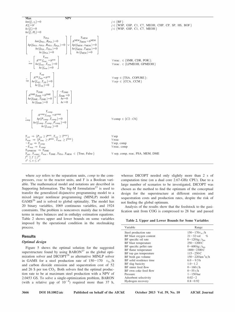
Optimal design
Figure 5 shows the optimal solution for the suggested
superstructure found by using BARON27 as the global opti-
mization solver and DICOPT28 as alternative MINLP solver
in GAMS for a steel production rate of 1502170 t ls =h
and carbon dioxide emission and sequestration cost of 52
and 26 $ per ton CO2. Both solvers find the optimal produc-
tion rate to be at maximum steel production with a NPV of
2.0453 G$. To solve a single-optimization problem, BARON
(with a relative gap of 1024) required more than 37 h,
whereas DICOPT needed only slightly more than 2 s of
computation time (on a dual core 2.67-GHz CPU). Due to a
large number of scenarios to be investigated, DICOPT was
chosen as the method to find the optimum of the conceptual
design for the superstructure at different emission and
sequestration costs and production rates, despite the risk of
not finding the global optimum.Analysis of the results show that the feedstock to the gasi-
fication unit from COG is compressed to 28 bar and passed
Table 2. Upper and Lower Bounds for Some Variables
Variable Range
Steel production rate 1502170 t st =hBF blast oxygen content 21232 vol %BF specific oil rate 02120 kg =thm
BF blast temperature 25021200 CBF specific pellet rate 02600 kg =thm
BF flame temperature 180022300 CBF top gas temperature 1152250 CBF bosh gas volume 1502220 km 3n=hBF solid residence time 6:0 2 9:5 hBF slag basicity 1:021:2BF sinter feed flow 02160 t=hBF own coke feed flow 0255 t=hPressure 12150 barAdsorbent selectivity 0:0222Hydrogen recovery 0:820:92
3666 DOI 10.1002/aic Published on behalf of the AIChE October 2013 Vol. 59, No. 10 AIChE Journal

through a heat exchanger to reach the operational conditionof the feed stream of the PSA for hydrogen separation. Thehydrogen recovery and adsorbent selectivity values take ontheir upper and lower boundary values (0.92 and 0.02),respectively. The top product stream is sent to the methanolplant and the bottom stream, which is methane enriched, ispartly sent to power plant and to the partial oxidation reac-tor. The cooled product of reaction is sent to the methanolplant. The mixture of BF and BOF gases passes through aheat exchanger to attain the required temperature for carbonmonoxide recovery in the TSA step. The product stream isconsidered to distribute between the water gas shift reactorto produce more hydrogen and the polygeneration plant.
The bottom byproducts of TSA and water gas shift aresent to the CO 2 capturing unit. The removed carbon dioxideis compressed to 100 bar for sequestration. The byproductof the chemical absorption unit contains mainly nitrogen andhydrogen. This stream is also compressed to 110 bar and
sent to PSA to separate hydrogen and nitrogen. The hydro-gen recovery and adsorbent selectivity parameter are esti-mated to be 0.90 and 0.02, respectively. The recoveredhydrogen is sent to the methanol unit and the bottom prod-uct, which is mostly nitrogen, is purged to the atmosphere.The products of the methanol reactor are cooled to 318 K,where methanol, DME, and water are condensed and puri-fied, and the residual gases are sent to the power plant. Table3 shows some of the optimal variables for the system (leftcolumn) and the results of a sequential NLP optimization ofan integrated steelmaking with complex BF model and steamreforming plant.8
The results show that in the optimal operation conditionof the integrated system, the BF works at lower coke rateand lower blast temperature which leads to no extra fuels inpower plant. On the other hand, with lower exporting carbonas byproduct (methanol) from the system, both the specificemission of carbon dioxide per liquid steel and steel costdecrease.
Optimal conditions at constant steel production rate
The optimal design of an integrated steel plant with a pol-ygeneration system coproducing methanol, electricity, anddistrict heat is next investigated in different scenarios of car-bon dioxide sequestration and emission costs. Even thoughthe penalty for carbon emissions in the European union (EU)
Table 3. Optimal Process Variables for the System with a
Steel Production Rate of 170 tls/h, Costs of Emissions ce5 52
$/tCO2, and Sequestration cseq5 26 $/tCO2
Variable a b
Blast volume (km3n/h) 123.6 126.8Blast oxygen (vol %) 27.8 28.0BFG volume (km3n/h) 199.1 203.0Sinter feed rate (t/h) 160.0 160.0
Specific coke rate (kg/thm) 309.4 320.7Specific oil rate (kg/thm) 120.0 120.0
Specific pellet rate (kg/thm) 459.4 457.6Flame temperature (�C) 2300 2246Blast temperature (�C) 990 1200
Bosh gas volume (km3n/h) 181.0 186.0Top gas temperature (�C) 128.0 143.0Burden residence time (h) 7.4 7.3Slag rate (kg/thm) 216.0 216.4COG volume (km3n/h) 17.6 17.6BOFG volume (km3n/h) 6.2 6.5Aux. fuel excluding BF (t/h) 0.0 9.3Bought/sold coke (t/h) 0.0 0.0Sold methanol (t/h) 18.8 28.6Specific emission (tCO2/tls) 0.97 1.50Specific steel cost ($/tls) 311.2 334.6
The left column is the results for present study and the right column data arefrom earlier work by the authors.8 Boldface denotes a value at its constraint.aIntegrated steelmaking with blast furnace surrogate model, auxiliary oilinjection, and POR/MEOH Plant (MINLP model).bIntegrated steelmaking with complex blast furnace model, auxiliary oilinjection, and SMR/MEOH plant (NLP model8).
Figure 5. Optimal process designs for the polygeneration system.
PSA: pressure swing adsorption, POR: partial oxidation reactor, GP: gas-phase methanol rector, FS-GP: gas separation unit,
DME: dimethyl ether purification, MEOH: methanol purification, TSA: temperature swing adsorption, WGS: water gas shift reac-
tor, CCA: CO2 chemical absorption. [Color figure can be viewed in the online issue, which is available at wileyonlinelibrary.com]
Figure 6. Net present value at different specific emis-sion and sequestration costs for a hot metalproduction rate of 150 thm/h.
AIChE Journal October 2013 Vol. 59, No. 10 Published on behalf of the AIChE DOI 10.1002/aic 3667

has varied on a low level (5–20 e/tCO2), it has been esti-mated that a tax level of 50–100 e/tCO2 in the future wouldbe necessary for making a sufficient impact on industrialproduction. Likewise, the estimated costs of CO2 storage,including liquefaction and transport, vary considerablydepending on the location and deposition technology. There-fore, the two costs were varied within a large range (0–150$/ tCO2) in this study.
Figure 6 shows the NPV of the system as a function ofcarbon dioxide emission and sequestration costs. The resultsestimate a 2.5 G$ change between the lowest and the highestcost scenarios. They show that the effect of the emissioncost on the NPV is stronger at high sequestration cost, andthat it is higher than the effect of the sequestration cost.
Figure 7 depicts the specific emissions (i.e., ton carbondioxide per ton liquid steel) from the system at constant hotmetal production rate (150 thm/h) and carbon dioxide emis-sion and sequestration costs of 0–150 $/tCO2. In different
scenarios, the specific carbon dioxide emission changes from0.68 tCO2/tls to 1.05 tCO2/tls, which is clearly lower than for acorresponding conventional steel plant (1.6–1.7 tCO2/tls).Quite naturally, the lowest specific emission is obtained fora high emission price and low sequestration cost. The analy-sis shows that at higher sequestration cost the model prefersthe CDR process and, therefore, part of the carbon dioxidehas been sent to the MG unit. For high carbon dioxide emis-sion cost and low sequestration cost, a higher amount of car-bon dioxide is sent for sequestration and the LP methanolreactor has been the choice. The MP for the different scenar-ios is estimated to be between 18 and 23 t/h. Finally, it isinteresting to note that the specific emissions exhibit a pla-teau (i.e., are constant) for the optimal states in the caseswhere the cost of emission roughly equals the cost ofsequestration.
Sensitivity analysis of main raw materials and products
A simple sensitivity analysis was undertaken to estimatethe effect of changing the main feedstock material and prod-uct prices at a constant steel production rate (170 tls/h)and costs of emission and sequestration of 52 $/tCO2 and26 $/tCO2. The variation of the NPV of the system by achange of 650% in the price of the main four input materials(oil, coal, ore, and pellets) and four products (methanol, steel,electricity, and district heat) is depicted in Figure 8. Asexpected, it illustrates that the NPV increases by increasingthe price of products and decreases by increasing the prices ofthe feed materials. The oil rate does not have the same effecton NPV because by decreasing the price of oil the MPincreases and more oil has to be used in the power plant. Inthe considered scenario of emission and sequestration costs,changing the price of electricity and district heat does nothave any effect on NPV as no external electricity and districtheat are produced in the optimal states. Obviously, the steelprice is of primary importance among the products and rawmaterials: for a 50% increase in the price of steel, the NPV ofthe system increases by 1138%, while no feasible solutionwas found if the price of liquid steel decreases by50%.
Figure 7. Optimal specific emission at different carbondioxide emission and sequestration costs fora hot metal production rate of 150 thm/h.
Figure 8. Optimal net present value for a 650% change in main raw material and product costs at a constant pro-duction rate of 170 tls/h and cost of emission and sequestration of 52 $/tCO2 and 26 $/tCO2.
3668 DOI 10.1002/aic Published on behalf of the AIChE October 2013 Vol. 59, No. 10 AIChE Journal

Optimal conditions for variable hot metalproduction rate
Table 4 reports the optimal liquid steel production cost,NPV and specific carbon dioxide emission, and MP ratefor different hot metal production rates at constant carbondioxide emission, and sequestration costs of 52 and 26 $/tCO2. The results illustrate that by increasing the produc-tion rate, liquid steel cost increases and specific CO2
emission slightly decreases while both NPV and MPincreases.
Multiobjective optimization formulation
To find different states of optimal operation, a set of sin-gle-objective optimization problems applying the e-constraintmethod4 was solved using MINLP solvers in GAMS to findthe optimal NPV s corresponding to given amounts of spe-cific emissions at constant CO 2 emission and sequestrationcosts (52 $/tCO2 and 26 $/tCO2). An advantage of a multiob-jective approach is that it provides solutions from which onemay select a suitable compromise based on both economicand environmental aspects. Because the objectives are non-dominated, they can be represented as a Pareto Frontier in adiagram, compare Figure 9.
The results show that for lower emission states CDR andLP methanol reactor and for higher NPV s POR and GPmethanol reactor are dominant unit processes. In all states,TSA is selected for carbon monoxide recovery, PSA forhydrogen recovery, and amine-based chemical absorption forcarbon dioxide capturing. Table 5 shows some of the varia-bles (main inputs and outputs from the system) extractedfrom the model for the four points (1–4) indicated in Figure9. Due to relaxed constraints on external district heat andelectricity in the power plant and the price of them, no exter-nal district heat and electricity is produced. In the low emis-sion scenario (cf. point 1), a supply of external coke, eventhough it is more expensive, is needed (for “outsourcing theemissions”), resulting in increase in the production costs ofsteel. To reach the minimum emission from the integrated
Table 4. Specific Emissions, Liquid Steel costs, Net Present
Value, and Methanol Production Rate for Different Hot
Metal Production Rates
ProductionRate
Specific CO2
EmissionLiquid
Steel CostNet Present
ValueMethanol
Production(thm/h) (tCO2/tls) ($/tls) (G$) (t/h)
130 1.02 307.6 1.82 15.1135 1.01 308.4 1.88 15.7140 0.99 309.6 1.95 16.5145 0.99 311.0 2.00 17.3150 0.98 311.3 2.06 19.5
Costs of emission and sequestration are constant (52 $/tCO2 and 26 $/tCO2).
Figure 9. Pareto frontier for maximization of net present value and minimization of specific emission rate for asteel plant integrated with a polygeneration system, at a hot metal production rate of 150 thm/h and con-stant costs of emission and sequestration (52 $/tCO2 and 26 $/tCO2).
Points 1–4 indicated by arrows refer to the optimal states reported in detail in Table 5.
Table 5. Results from the Model for Four Selected Point in
the Frontier Diagram (Figure 9).
1 2 3 4
NPV (G$) 0.49 1.28 1.89 2.05Specific emission (tCO2/tls) 0.45 0.55 0.75 0.98Coal flow rate (t/h) 0.0 0.0 80.1 80.2Ore flow rate (t/h) 133.1 133.1 153.6 153.6External coke rate (t/h) 56.1 52.6 0.0 0.0Limestone rate (t/h) 25.1 24.8 23.5 23.5Quartzite rate (t/h) 0.0 0.0 0.0 0.0Pellet rate (t/h) 90.0 90.0 70.2 70.2Air volume rate (knm3/h) 106.5 113.0 113.0 113.0Oxygen flow rate (knm3/h) 22.0 17.3 17.8 18.7Slag rate (kg/thm) 220 218.4 216.2 216.2Scrap rate (t/h) 37.5 37.5 37.5 37.5Nitrogen flow rate (t/h) 47.2 56.0 56.0 56.0DME flow rate (t/h) 0.0 0.0 0.0 0.6Oil flow rate (t/h) 21.64 21.9 18.0 18.0CO2 sequestrated (t/h) 148.7 118.8 116.1 81.6Methanol production (t/h) 23.4 20.9 21.2 19.3Steel cost ($/tls) 358.4 355.1 300.3 311.0
Data are estimated by using MINLP solvers in GAMS and maximum NPV isreported.
AIChE Journal October 2013 Vol. 59, No. 10 Published on behalf of the AIChE DOI 10.1002/aic 3669

steelmaking plant studied, an increase of more than 50 $/tlswould be expected in the costs of steel production.
Conclusions and Future Work
In this article, a superstructure for an integrated steelmak-ing plant combined with a polygeneration system has beenproposed to find optimal operation and design states withrespect to process economics for different scenarios of car-bon dioxide emission and sequestration costs. Generalizeddisjunctive programming was used to model the system andto investigate both profitability and environmental impactswhile optimizing the mass and energy flows in the systemaccording to different technologies. The results show that byapplying a process integration approach it is possible to sup-press half of the emissions from a conventional steelmakingplant. Depending on the importance given to low costs orlow emission rates, the solutions of a multiobjective formula-tion illustrated that different design concepts were applied indifferent regions.
Future work will be focused on an analysis of using alter-native fuels, such as natural gas and biomass, in the system,also considering different BF technologies, such as top gasrecycling and cold oxygen injection. The study could also beextended to steelmaking plants with multiple BFs, andshould also consider the end units of the steelmaking pro-cess, that is, continuous casting and rolling. It would also bepossible to study the system with a focus on different prod-uct demands to gain insight into how steelmaking could bedeveloped in a more sustainable direction.
Acknowledgments
Financial support from the Academy of Finland within theSYMBIOSIS project and from the Fortum foundation, Fin-land, are gratefully acknowledged. H.G. would also like tothank the CAPD members and visitors in Carnegie MellonUniversity for their support.
Literature Cited
1. Liu P, Pistikopoulos EN, Li Z. A mixed-integer optimizationapproach for polygeneration energy systems design RID C-4913-2011 RID E-7840-2011. Comput Chem Eng. 2009;33:759–768.
2. Zhang Y, Ni W, Li Z. Research on superclean polygeneration energysystem of iron and steel industry. In: Power and Energy Systems,Proceeding of the 7th IASTED International Conference on Powerand Energy Systems. Anaheim: Acta Press, 2004:152–157.
3. Liu P, Gerogiorgis DI, Pistikopoulos EN. Modeling and optimizationof polygeneration energy systems RID C-4913-2011. Catal Toda y.2007;127:347–359.
4. Liu P, Pistikopoulos EN, Li Z. A Multiobjective optimizationapproach to polygeneration energy systems design RID C-4913-2011RID E-7840-2011. AIChE J. 2010;56:1218–1234.
5. Chen Y, Adams TA II, Barton PI. Optimal design and operation offlexible energy polygeneration systems. Ind Eng Chem Res. 2011;50:4553–4566.
6. Chen Y, Adams TA II, Barton PI. Optimal Design and Operation ofStatic Energy Polygeneration Systems. Ind Eng Chem Res.2011;50:5099–5113.
7. Ghanbari H, Helle M, Pettersson F, Saxen H. Optimization study ofsteelmaking under novel BF operation combined with methanol pro-duction. Ind Eng Chem Res. 2011;50:12103–12112.
8. Ghanbari H, Helle M, Sax�en H. Process integration of steelmakingand methanol production for suppressing CO2 emissions—a study ofdifferent auxiliary fuels. Chem Eng Process. 2012;61:58–68.
9. Helle H, Helle M, Saxen H. Nonlinear optimization of steel produc-tion using traditional and novel blast furnace operation strategies.Chem Eng Sci. 2011;66:6470–6481.
10. “PLS_Toolbox 6.5.2” Advanced Chemometrics software for use withMatlab, Eigenvector research incorporated, 2011. Accessible at:http://www.eigenvector.com/software/pls_toolbox.htm
11. Lophaven SN, Nielsen HB, Sondergaard J. Aspects of the Matlabtoolbox DACE, IMM-REP-2002-13, 2002; Accessible at: http://www2.imm.dtu.dk/~hbni/dace/
12. Costello R. COPureSM Process; R.C. Costello & Assoc, Inc., Privatecommunication, 2011.
13. Rabo JA, Francis JN, Angell CL. Selective adsoption of carbonmonoxide from gas streams, Patent US4019879 A, 1977.
14. Olajire AA. CO2 capture and separation technologies for end-of-pipeapplications—a review. Energy. 2010;35:2610–2628.
15. Tobiesen FA, Svendsen HF, Mejdell T. Modeling of blast furnaceCO2 capture using amine absorbents. Ind Eng Chem Res. 2007;46:7811–7819.
16. Lie JA, Vassbotn T, H€agg M, Grainger D, Kim T, Mejdell T. Opti-mization of a membrane process for CO2 capture in the steelmakingindustry. Int J Greenh Gas Control. 2007;1:309–317.
17. Ruthven DM, Farooq S, Knaebel KS. Pressure Swing Adsorption.VCH Wiley, October 1, 1993, ISBN-10: 0471188182, ISBN-13:978-0471188186.
18. Porter MC. The separation of gases by membrane. In: Handbook ofIndustrial Membrane Technology, William Andrew Publishing/Noyes, 1990:559. ISBN:978-0-8155-1205-9.
19. Henis JMS, Tripodi MK. Multicomponent Membrane for Gas Sepa-rations, Patent US4230463 A, 1980.
20. Van Dijk CP, Solbakken A, Rovner JM. Methanol from Coal andNatural Gas, Patent US4407973, 1983.
21. Wang S, Lu G, Millar G. Carbon dioxide reforming of methane toproduce synthesis gas over metal-supported catalysts: state of the artRID C-5507-2008 RID A-2859-2008. Energy Fuels. 1996;10:896–904.
22. Zhu J, Zhang D, King K. Reforming of CH4 by partial oxidation:thermodynamic and kinetic analyses. Fuel. 2001;80:899–905.
23. Biegler LT, Grossmann IE, Westerberg AW. Systematic Methods ofChemical Process Design. Upper Saddle River, NJ: Prentice HallPTR, 1997.
24. Vaswani S. Development of Models for Calculating the Life CycleInventory of Methanol by Liquid Phase and Conventional ProductionProcess. Department of Civil Engineering: Raleigh, NC, 2000.
25. The National Institute of Standards and Technology. NIST Chemis-try Webbook, 2011. Available online at http://webbook.nist.gov/chemistry/.
26. GAMS Development Corporation, 2011. GAMS (General AlgebraicModeling System) Software v23.7.3. Available at: http://www.gams.com.
27. Tawarmalani M, Sahinidis N. A polyhedral branch-and-cut approachto global optimization. Math Program. 2005;103:225–249.
28. Duran M, Grossmann I. An outer-approximation algorithm for aclass of mixed-integer nonlinear programs. Math Program. 1986;36:307–339.
Manuscript received Jul. 19, 2012, revision received Dec. 7, 2012, and finalrevision received Mar. 16, 2013.
3670 DOI 10.1002/aic Published on behalf of the AIChE October 2013 Vol. 59, No. 10 AIChE Journal