optimal coordination of overcurrent relays in distribution...
TRANSCRIPT

Optimal coordination of overcurrent relays in distribution systemswith distributed generators based on differential evolution algorithm
Hui Yang1, Fushuan Wen2,3*,† and Gerard Ledwich3
1Zhuhai Polytechnic, Zhuhai 519015, China2School of Electrical Engineering, Zhejiang University, Hangzhou 310027, China
3School of Engineering Systems, Queensland University of Technology, Brisbane Queensland 4001, Australia
SUMMARY
Distributed generators (DGs) are defined as generators that are connected to a distribution network. The directionof the power flow and short-circuit current in a network could be changed compared with one without DGs. Theconventional protective relay scheme does not meet the requirement in this emerging situation. As the number andcapacity of DGs in the distribution network increase, the problem of coordinating protective relays becomes morechallenging. Given this background, the protective relay coordination problem in distribution systems is investi-gated, with directional overcurrent relays taken as an example, and formulated as a mixed integer nonlinearprogramming problem. A mathematical model describing this problem is first developed, and the well-developeddifferential evolution algorithm is then used to solve it. Finally, a sample system is used to demonstrate the feasi-bility and efficiency of the developed method. Copyright © 2011 John Wiley & Sons, Ltd.
key words: distributed generation; distribution system; coordination of protective relays; directional relay;differential evolution algorithm
1. INTRODUCTION
A distributed generator (DG) is usually defined as a small-scale generator with a capacity between3 kW and 100MW [1] and is normally connected to a distribution network. Distributed generationis helpful for improving the distribution system’s operation and power supply, especially in ruraland remote areas [2]. Specifically, the advantages of DG can be summarized as follows: enhancingreliability, reducing network losses, improving power quality, postponing network expansion, improv-ing the environment by reducing carbon dioxide and nitrogen oxide emissions, and providing peakload service [3–6]. In recent years, distributed generation has developed rapidly as a result of therestructuring of the power industry and the environmental concerns of people around the globe [7].However, the rapid increase in the number and capacity of DGs has also brought some problems to power
system operation and control [7–12]. Whether the abovementioned advantages of DGs can be achieveddepends heavily on the proper resolution of these problems; one important issue is the coordination ofprotective devices [13,14]. Traditionally, the distribution system operates in a radial configuration,and its power flow and short-circuit current are flowing in one direction only. The inclusion of DGsin a distribution network could change the direction of the power flow and the short-circuit current.If conventional overcurrent protection/overcurrent relay systems are still used, malfunctions in protec-tion may happen because of the change in the direction of the current. The conventional protectiverelay scheme does not meet the requirement in this emerging situation. As the number and capacityof DGs increase in the distribution system, the issues concerned, namely, the protective relay systemdesign and coordination, will become increasingly challenging [15]. It is expected that replacing pro-tective devices will incur large amounts of investment and may not be cost-effective. Instead, the
*Correspondence to: Fushuan Wen, School of Electrical Engineering, Zhejiang University, Hangzhou 310027, China.†E-mail: [email protected]
Copyright © 2011 John Wiley & Sons, Ltd.
EUROPEAN TRANSACTIONS ON ELECTRICAL POWEREuro. Trans. Electr. Power (2011)Published online in Wiley Online Library (wileyonlinelibrary.com). DOI: 10.1002/etep.635

problem may be resolved by appropriately coordinating the relay settings of the existing protectiverelays to achieve a cost-efficient outcome, at least for low levels of penetration of DGs.Protective relay coordination refers to the ability to select appropriate relay setting values so that
they can meet the basic requirements for protective relays, namely, selectivity, speed, sensitivity,and reliability [16], under different kinds of faults. An appropriately coordinated protection systemcan isolate faults quickly and maintain the operation of the remaining healthy part of the system[17]. Directional overcurrent relays are widely used in distribution systems; hence, it is very importantto investigate the coordination problem when using these protective relays [18]. Some research workhas been done in this area but, in most of the existing methods, linear or nonlinear programmingapproaches are used for this purpose [16]. Only continuous variables can be handled in theseapproaches, and thus the results obtained have to be rounded off to the nearest discrete value. Hence,the optimality of the coordination results cannot be maintained.Given this background, the optimal coordination problem of overcurrent relays is revisited and formulated
as a mixed integer nonlinear programming (MINLP) problem in this work. In the formulation, the pickupcurrent setting is a discrete variable, whereas the time setting multiplier is continuous. As each protective relayin the distribution system must be properly coordinated with the adjacent relays, the coordination of the pro-tection system could be very complicated. In this work, the well-established differential evolution (DE) algo-rithm [19] was used to solve this problem. The abovementioned problem of rounding the optimalsolution of continuous variables in existing methods can be avoided in this DE-based method. First,the mathematical model of the directional overcurrent relay coordination problem is formulated, withthe objective of minimizing the operating time of protective relays. Then, the DE algorithm is brieflyintroduced. Finally, a numerical example is presented to demonstrate the proposed approach.
2. THE MATHEMATICAL MODEL
2.1. Primary/backup coordinating pairs
The primary/backup coordinating pairs of overcurrent relays can be illustrated by a simple exampleshown in Figure 1. If a three-phase short-circuit fault occurs on bus C, the short-circuited current willflow from line AB to line BC. In this case, relay 1 is the primary protection and relay 2 the backupprotection. These two protection units form a coordinating pair and could be described as (R2, R1).For a general case, the set of coordinating pairs could be defined as RPB = {(RB, RP)}, where RP isthe primary protection and RB the backup protection. A coordination time interval should be imposedbetween a primary and a backup coordinating pair so as to maintain the selectivity and coordination.For this purpose, all the primary/backup coordinating pairs must first be found.
2.2. A uniform model for optimal coordination of relays
To facilitate the presentation, a general nonlinear programming model is first introduced:
Min : f xð Þ (1)
s:t: : g xð Þ ¼ 0 (2)
hmin≤h xð Þ≤hmax (3)
where f(x) is the objective function, x is the variable to be determined, g(x) = [g1(x),⋯, gm(x)]T, m is the
number of equality constraints, h(x) = [h1(x),⋯, hr(x)]T, r is the number of inequality constraints, hmax
12
A B C
If 2 If1
Figure 1. An illustration of a relay coordinating pair.
H. YANG ET AL.
Copyright © 2011 John Wiley & Sons, Ltd. Euro. Trans. Electr. Power (2011)DOI: 10.1002/ete

and hmin are the vectors of the upper and lower bounds for the inequality constraints, respectively,hmin = [h1min,⋯, hrmin]
T, and hmax = [h1max,⋯, hrmax]T.
As for the optimal coordination problem of protective relays in distribution systems, the objective isactually to minimize the operating time of relays under the constraints of selectivity, sensitivity,reliability, and relay characteristic curves. This problem could be formulated as an optimization model:
minx2X
f x; pð Þ (4)
s:t:: t ¼ g xð Þ relay characteristic functionð Þ (5)
h xð Þ≤0 coordination constraintð Þ (6)
xmin≤x≤xmax relay settings constraintð Þ (7)
tmin≤t≤tmax operating time constraintð Þ (8)
where f(x) is the objective function; x is the variable to be determined, that is, relay settings parameters;X is the set of available settings; p is a set of perturbations or fault conditions in a specified zone; and tis the operating time of a relay.In the previously mentioned optimization model, Equation (6) represents the selectivity constraint used
to maintain the selectivity between the primary protection and the backup protection. Equation (7)represents the sensitivity constraint used to make sure that a relay can operate when a fault occurs withinits protection range by appropriately setting the relay parameters. Equation (8) represents the reliabilityconstraint used to guarantee that when a fault occurs within a relay’s protection range, the relay mustoperate within the bounds of the operating time. In summary, the optimal coordination problem of pro-tective relays is that of minimizing the operating time of relays while respecting these constraints.
2.3. The optimization model of overcurrent relays
The minimization of the total operating time of a protective relay system under different fault zones istaken as the objective of the optimal coordination problem of protective relays. Specific to directionalovercurrent relays, the optimal coordination problem determines two parameters, that is, the pickupcurrent setting and the time setting multiplier. The objective function for the optimal coordinationproblem of directional overcurrent relays can be described as
min J ¼XNP
i¼1
witiL (9)
where NP is the number of primary and backup relays, wi is a coefficient representing the probability ofthe occurrence of a fault and could be set to 1 for all possible faults if reliable data are not available,and tiL is the operating time of the ith relay when a fault occurs in zone L.The smaller the objective function, the better the coordination of the protective relays. In the case of the optimal
solution, the total operating time of the protective relays in the protection system studied is minimized under allspecified faults. In this way, faults can be cleared quickly if they are included in the specified kinds of faults.In minimizing the objective function, some constraints must be taken into account, such as the relay current/
time characteristics, the constraints on the time setting multiplier and the operating time, the pickup currentsetting, and the coordination time of relays. These constraints are detailed in the following paragraphs.
(1) The relay current/time characteristics
The current/time characteristic curves of an overcurrent protection consist of two types, that is, thedefinite time and inverse time curves.
(a) The definite time characteristic relay
The operating time of a definite time characteristic relay is independent of the short-circuitedcurrent, and can be defined as
ti ¼ Cconst (10)
where ti is the operating time of relay Ri and Cconst is a constant.
OVERCURRENT RELAYS IN DISTRIBUTION SYSTEMS
Copyright © 2011 John Wiley & Sons, Ltd. Euro. Trans. Electr. Power (2011)DOI: 10.1002/ete

If the definite time characteristic relays are used for the optimal coordination of overcurrent relaysin distribution systems, the objective function is Equation (9) and the constraints are Equations (13)and (14). It is obvious that the optimality analysis is not demanded in a radial distribution system if thefault current is larger than the pickup current because the operating time of all relays could be obtainedby the backward process on the basis of the coordination time interval, as long as the operating time ofthe relay at the end of the feeder concerned is known. Hence, the definite time characteristic relay is usu-ally not considered in the optimal coordination problem of overcurrent relays in distribution systems.
(b) The inverse time characteristic relay
The operating time of the inverse time characteristic relay is dependent on the short-circuited cur-rent. The larger the current is, the shorter the operating time will be. To some extent, this characteristicis adaptive. The current/time characteristic of a directional overcurrent relay under the Institute forElectrical and Electronic Engineers (IEEE) standard C37.112-1996 and IEC 255–3 can be expressed as
tiL ¼ TMi � lIiLIPi
� �g� 1
(11)
where TMi is the time setting multiplier, IiL is the short-circuited current passing through the relay whena fault occurs in zone L, IPi is the pickup current setting of the ith relay, and l and g are constants.
(2) Constraints on the time setting multiplier and the operating time
TMimin≤TMi≤TMimax (12)
timin≤ti≤timax (13)
where TMi is in the range of 0.01 to 1.
(3) Constraints on the pickup current setting
Because the pickup current setting of each overcurrent protective relay is discrete, a 0–1 variable ymiis usually used in the existing methods [16], and the setting can be represented by the product of thepickup current–specified value and a binary variable. For example, if a relay has eight available relaypickup current–specified values, the pickup current setting can be formulated as
IP1 ¼ y11IPa1 þ y21IPa2 þ y31IPa3 þ y41IPa4 þ y51IPa5 þ y61IPa6 þ y71IPa7 þ y81IPa8 (14)
where IPa1, IPa2, . . ., IPa8 are the available relay pickup current–specified values. Equation (14) can bereformulated as
IPi ¼Xm
ymiIPam8i wherei ¼ 1; 2; . . . ; n (15)
ymi ¼ 1 IPi ¼ IPam0 otherwise
�(16)
where n is the number of the relays, m is the number of the available relay pickup current–specifiedvalues, and IPam is the mth relay pickup current setting for the ith relay.To make sure that an available relay pickup current–specified value can be chosen for each relay, the
following constraint has to be imposed on ymi,Xm
ymi ¼ 1 8i where i ¼ 1; 2; . . . ; n (17)
It can be seen from Equation (17) that if one of the binary variables for a relay is equal to 1, then allthe others for the same relay will be 0.However, the number of control variables is usually very large and the computational efficiency is
low in the existing methods. Given this background, an alternative method is presented here in whichinteger variables are used rather than binary variables. Specifically, each value of an integer variablerepresents an available relay pickup current. In this way, each relay has only one integer variable, sothe numbers of the control variables can be reduced significantly. On this basis, the well-developedDE [19] will be used to solve the problem.
H. YANG ET AL.
Copyright © 2011 John Wiley & Sons, Ltd. Euro. Trans. Electr. Power (2011)DOI: 10.1002/ete

In addition, the pickup current setting Ipi of each overcurrent relay must meet the followingconstraint:
IPimin≤IPi≤IPimax (18)
From Equation (18), it can be observed that the pickup current setting for each relay is determinedby two parameters, namely, the minimum fault current and the maximum load current [18]. The min-imum pickup current is generally specified as being 1.5 to 2 times of the normal load current to main-tain the secure operation of the power system concerned. The maximum pickup current is determinedsuch that it is less than the fault current passing through the relay to activate the operation of the relaywhen a fault occurs [20].
Global solution
)( 1rjx
)( 2rjx
(best)jx
)(ijx
')(ijx
A
B
C
Local solution
O
Figure 2. The reproduction mechanism of the DE algorithm.
Start
initialization
Finding out the initial best individual
k=k+1
Reproduction
k < Max generation size
Selection
Fitness Evaluation for each individual
k=1
Finish
Y
N
Find the best individual
Figure 3. The flowchart of the DE algorithm.
OVERCURRENT RELAYS IN DISTRIBUTION SYSTEMS
Copyright © 2011 John Wiley & Sons, Ltd. Euro. Trans. Electr. Power (2011)DOI: 10.1002/ete
(4) Constraints on the coordination time interval of protective relays
When a primary protective relay does not operate properly, a backup protective relay must operateto isolate the fault. The coordination time interval is the difference between the operating time of thebackup relay and that of the primary protective relay. This is the minimum time interval that permitsthe backup relay to clear a fault in its operating zone. Equation (19) is a fundamental constraint forthe optimal coordination problem of protective relays:
tbL � tiL≥CTI (19)
where tbL is the operating time of the backup relay Ri when a fault occurs in zone L and CTI is thecoordination time interval, usually specified between 0.2 and 0.5 s [16].In the previously mentioned mathematical model, both discrete and continuous variables are
included, and the objective function is nonlinear. Hence, this is an MINLP problem. In this work,the well-established DE algorithm is used to solve this MINLP problem.
3. THE DE ALGORITHM
The DE algorithm was advanced by Rainer Storn and Kenneth Price in 1995 [19] and represents asimple and effective evolutionary algorithm. The DE algorithm is proven faster than other evolutionaryalgorithms such as evolution strategy [21]. In 1999, Jouni Lampinen and Ivan Zelinka extended the DEalgorithm to solve optimization problems with mixed variables and constraints, which promoted thewider use of the DE algorithm [19].
1
2
3
4
5
6
7
8BS
BDG
S
DG
A B
C D
E F10
9
11 BDG'
DG'
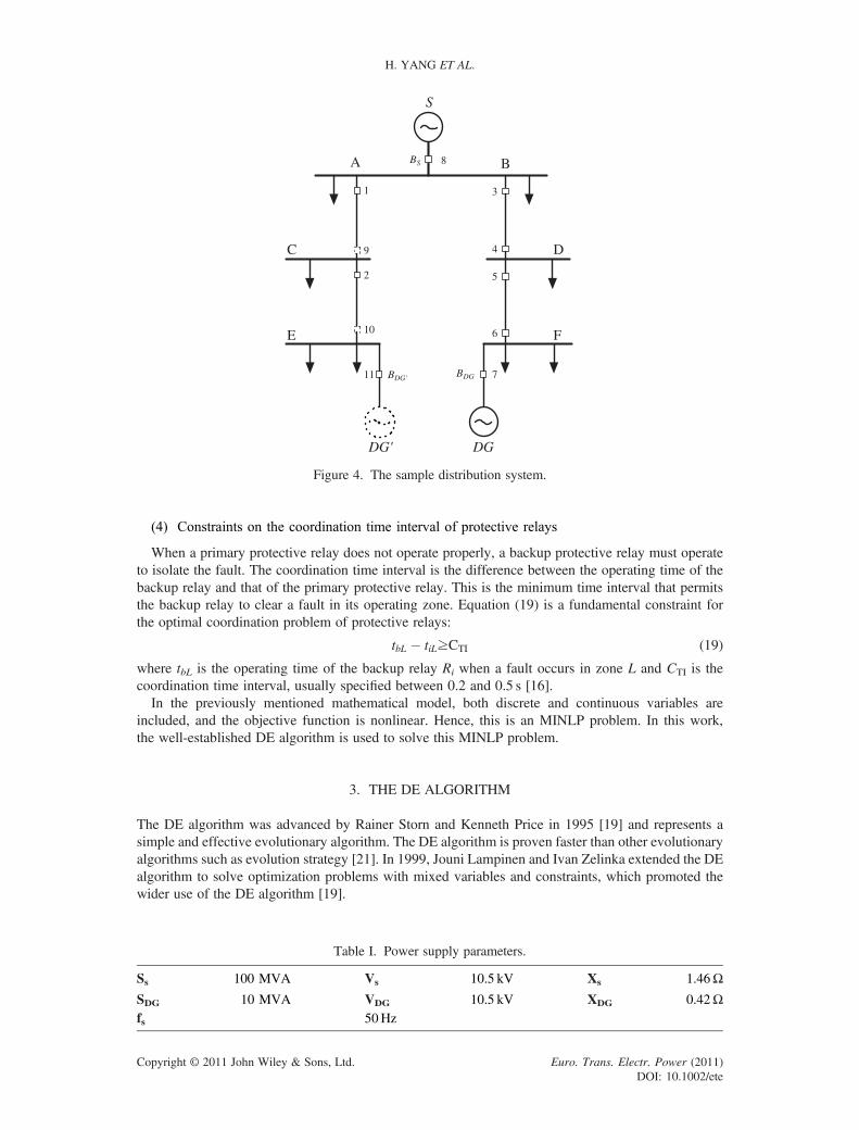
Figure 4. The sample distribution system.
Table I. Power supply parameters.
Ss 100 MVA Vs 10.5 kV Xs 1.46Ω
SDG 10 MVA VDG 10.5 kV XDG 0.42Ωfs 50Hz
H. YANG ET AL.
Copyright © 2011 John Wiley & Sons, Ltd. Euro. Trans. Electr. Power (2011)DOI: 10.1002/ete
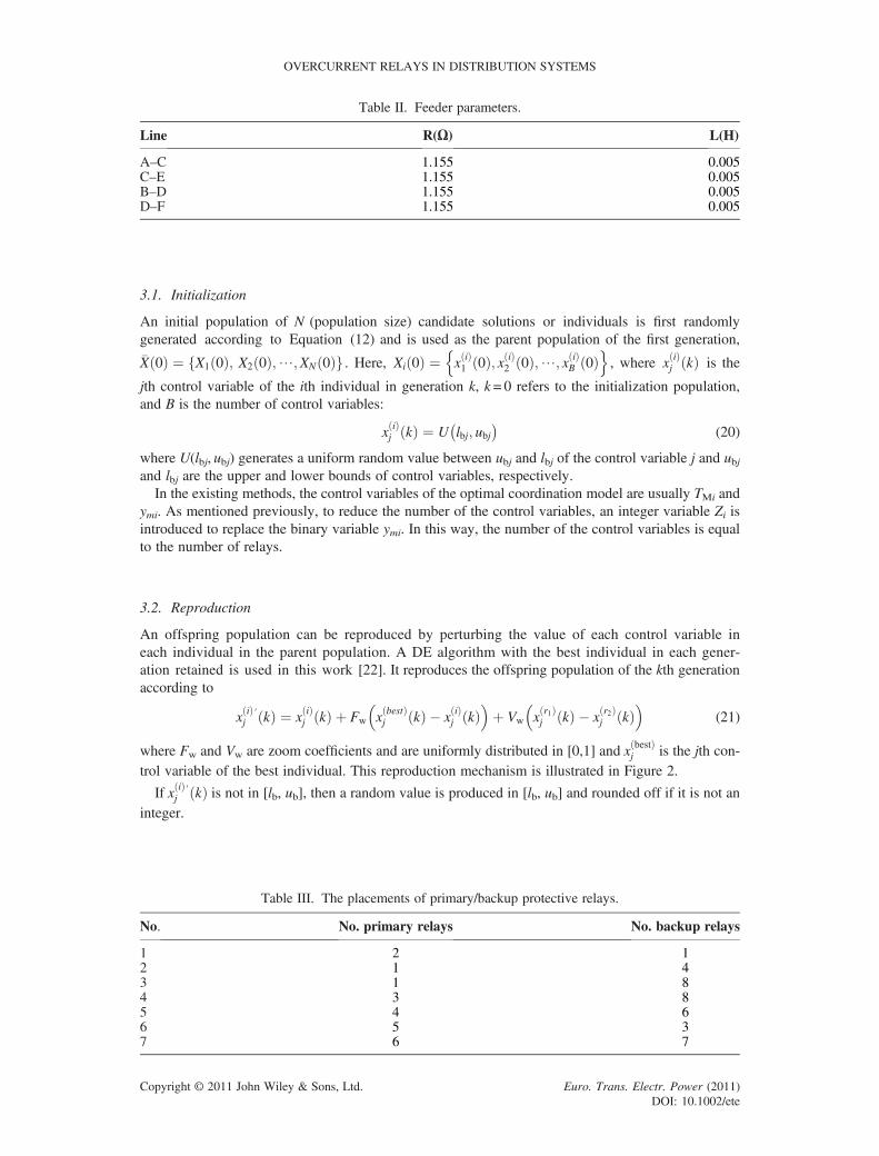
3.1. Initialization
An initial population of N (population size) candidate solutions or individuals is first randomlygenerated according to Equation (12) and is used as the parent population of the first generation,�X 0ð Þ ¼ X1 0ð Þ; X2 0ð Þ;⋯;XN 0ð Þf g . Here, Xi 0ð Þ ¼ x ið Þ
1 0ð Þ; x ið Þ2 0ð Þ;⋯; x ið Þ
B 0ð Þn o
, where x ið Þj kð Þ is the
jth control variable of the ith individual in generation k, k = 0 refers to the initialization population,and B is the number of control variables:
x ið Þj kð Þ ¼ U lbj; ubj
� �(20)
where U(lbj, ubj) generates a uniform random value between ubj and lbj of the control variable j and ubjand lbj are the upper and lower bounds of control variables, respectively.In the existing methods, the control variables of the optimal coordination model are usually TMi and
ymi. As mentioned previously, to reduce the number of the control variables, an integer variable Zi isintroduced to replace the binary variable ymi. In this way, the number of the control variables is equalto the number of relays.
3.2. Reproduction
An offspring population can be reproduced by perturbing the value of each control variable ineach individual in the parent population. A DE algorithm with the best individual in each gener-ation retained is used in this work [22]. It reproduces the offspring population of the kth generationaccording to
x ið Þj
′ kð Þ ¼ x ið Þj kð Þ þ Fw x bestð Þ
j kð Þ � x ið Þj kð Þ
� �þ Vw x r1ð Þ
j kð Þ � x r2ð Þj kð Þ
� �(21)
where Fw and Vw are zoom coefficients and are uniformly distributed in [0,1] and x bestð Þj is the jth con-
trol variable of the best individual. This reproduction mechanism is illustrated in Figure 2.
If x ið Þj
′ kð Þ is not in [lb, ub], then a random value is produced in [lb, ub] and rounded off if it is not aninteger.
Table II. Feeder parameters.
Line R(Ω) L(H)
A–C 1.155 0.005C–E 1.155 0.005B–D 1.155 0.005D–F 1.155 0.005
Table III. The placements of primary/backup protective relays.
No. No. primary relays No. backup relays
1 2 12 1 43 1 84 3 85 4 66 5 37 6 7
OVERCURRENT RELAYS IN DISTRIBUTION SYSTEMS
Copyright © 2011 John Wiley & Sons, Ltd. Euro. Trans. Electr. Power (2011)DOI: 10.1002/ete

3.3. The evaluation of individuals
A fitness function is defined for evaluating the fitness of each individual as
f Xi kð Þð Þ ¼1� Fv �
Phi¼1
CiPtiL
(22)
where f( ) is the fitness function, Fv is a penalty coefficient, h is the number of constraints, and C is thepenalty value and is equal to 1 when it meets the constraint and 0 otherwise.
3.4. Selection
The selection strategy in the DE algorithm is very easy and can be described as a “one-to-one” selec-
tion. An offspring individual x ið Þ′ kð Þ is compared with its parent individual x ið Þj kð Þ, and the better one
wins. The winning individuals form the updated population of generation k, which will then be used asthe parent population of the next generation:
Xi k þ 1ð Þ ¼ x ið Þj
′ kð Þ; if f x ið Þj
′ kð Þ� �
> f x ið Þj kð Þ
� �x ið Þj kð Þotherwise
8<: (23)
Table IV. Simulation results.
TMi Result IPi Result (A)
TM1 0.0196 IP1 1100TM2 0.0195 IP2 400TM3 0.0192 IP3 1100TM4 0.0565 IP4 100TM5 0.0120 IP5 600TM6 0.0136 IP6 1000TM7 0.0689 IP7 800TM8 0.0782 IP8 1000Objective value(s) 4.8576Fitness value 0.2059
Figure 5. The objective value of the best individual and that of a given individual.
H. YANG ET AL.
Copyright © 2011 John Wiley & Sons, Ltd. Euro. Trans. Electr. Power (2011)DOI: 10.1002/ete

3.5. Termination
The procedure will be terminated after a specified number of generations. The number of generationsrequired to carry out the optimal coordination of protective relay settings depends on the populationsize and the number of initial relay settings. The flowchart of the DE algorithm is shown in Figure 3.
4. NUMERICAL EXAMPLES
In this work, the sample system by Zeienldin et al. [23] is slightly modified to demonstrate the devel-oped approach, as shown in Figure 4. It is obvious that when DGs are removed, the original system is aradial network, whereas when DGs are added, the distribution system will become a looped one, andthe power flow as well as short-circuited current will no longer flow in just one direction. Directionalovercurrent relays could be used to protect the system. In this work, bus faults are used in case studies,but the developed mathematical model and algorithm could be applied to a variety of fault locations aswell as different types of faults, as long as the constraints are included and respected. To keep theradial characteristic in the original distribution system and to solve the new problems mentioned, thecase study is chosen with a DG installed at the end of feeder B. If another DG is installed at the endof feeder A, as shown with the broken line in Figure 4, three protective relays should be installed.
0 10 20 30 40 50 60 70 80 90 1000
0.5
1
1.5
2
2.5
3
Mis
mat
ched
num
ber
Generations
Figure 6. The mismatched number of protective relays in the best individual and a given individual.
0 10 20 30 40 50 60 70 80 90 1000
0.1
0.2
0.3
0.4
0.5
0.6
0.7
TM
1 of
rel
ay #
1 fo
r a
give
n in
divi
dual
Generations
Figure 7. TM1 of relay 1 for a given individual.
OVERCURRENT RELAYS IN DISTRIBUTION SYSTEMS
Copyright © 2011 John Wiley & Sons, Ltd. Euro. Trans. Electr. Power (2011)DOI: 10.1002/ete
In this case, the current direction through each protective relay does not change when a fault takesplace on a bus; the only change is the fault current amount. The mathematical model presented in thiswork can solve this situation.The system shown in Figure 4 is a 10-kV distribution system with five buses and eight protective
relays. A DG is installed at the end of feeder B. There are two circuit breakers; one at the public powersupply point and the other at the distributed generation supply point. The DE algorithm is used toobtain the optimal time setting multiplier (TM) and the pickup current setting value (IP) of the direc-tional overcurrent relay. The formulated model consists of 16 variables with eight discrete variablesand eight continuous variables by using the proposed method; however, there will be 72 variables witheight discrete variables and 64 continuous variables if the existing method is used. It should be pointedout that the proposed method can be applied to larger and more complicated distribution systems withmultiple DGs.The original data of the sample system are shown in Tables 1–3, which show the power supply para-
meters, the feeder parameters, and the placements of primary/backup protective relays, respectively.Many simulation tests have been carried out. The test results with the following specified parameters
are listed in Table 4: the initial population size was N= 300, and the maximum permitted number ofgenerations was 100. To better understand the computational procedure of the DE algorithm, somesimulation results are shown in Figures 5–7. The optimal objective value and the objective value ofa given individual in each generation are shown in Figure 5, the mismatched number of protectiverelays in the best individual and a given individual are shown in Figure 6, and the TM1 of relay 1 ofa given individual is shown in Figure 7.It is illustrated by the simulation results in Table 4 that the protective relays can remove all the three-
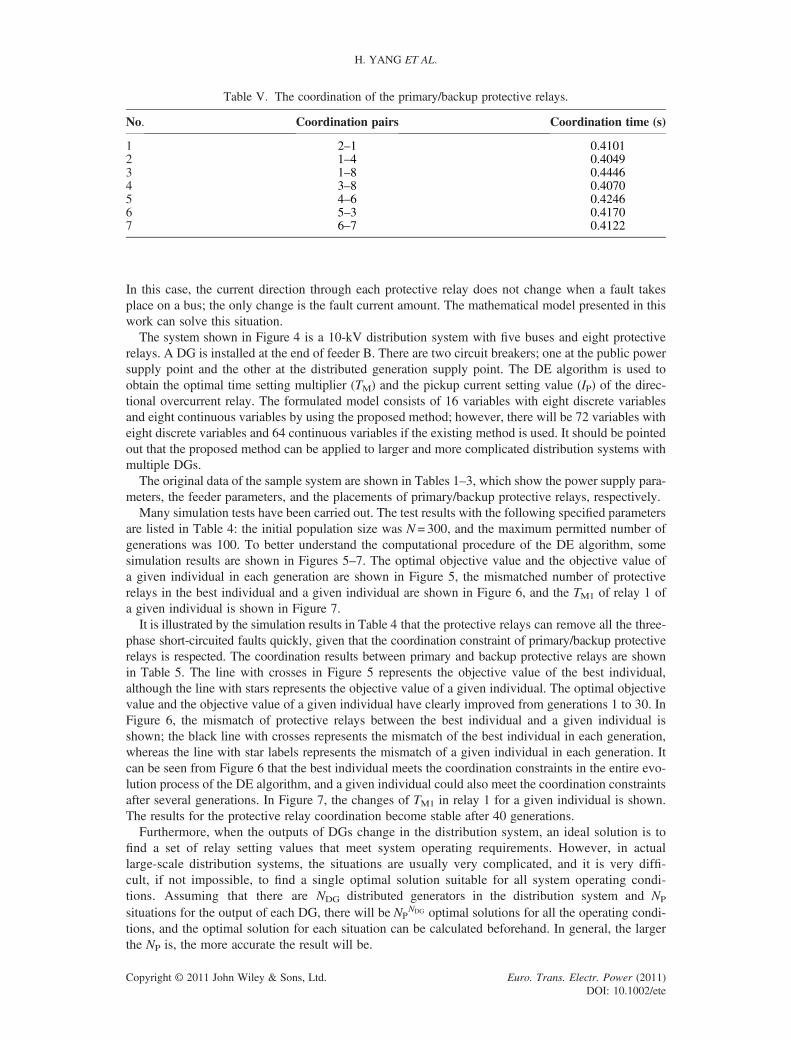
phase short-circuited faults quickly, given that the coordination constraint of primary/backup protectiverelays is respected. The coordination results between primary and backup protective relays are shownin Table 5. The line with crosses in Figure 5 represents the objective value of the best individual,although the line with stars represents the objective value of a given individual. The optimal objectivevalue and the objective value of a given individual have clearly improved from generations 1 to 30. InFigure 6, the mismatch of protective relays between the best individual and a given individual isshown; the black line with crosses represents the mismatch of the best individual in each generation,whereas the line with star labels represents the mismatch of a given individual in each generation. Itcan be seen from Figure 6 that the best individual meets the coordination constraints in the entire evo-lution process of the DE algorithm, and a given individual could also meet the coordination constraintsafter several generations. In Figure 7, the changes of TM1 in relay 1 for a given individual is shown.The results for the protective relay coordination become stable after 40 generations.Furthermore, when the outputs of DGs change in the distribution system, an ideal solution is to
find a set of relay setting values that meet system operating requirements. However, in actuallarge-scale distribution systems, the situations are usually very complicated, and it is very diffi-cult, if not impossible, to find a single optimal solution suitable for all system operating condi-tions. Assuming that there are NDG distributed generators in the distribution system and NP
situations for the output of each DG, there will be NPNDG optimal solutions for all the operating condi-
tions, and the optimal solution for each situation can be calculated beforehand. In general, the largerthe NP is, the more accurate the result will be.
Table V. The coordination of the primary/backup protective relays.
No. Coordination pairs Coordination time (s)
1 2–1 0.41012 1–4 0.40493 1–8 0.44464 3–8 0.40705 4–6 0.42466 5–3 0.41707 6–7 0.4122
H. YANG ET AL.
Copyright © 2011 John Wiley & Sons, Ltd. Euro. Trans. Electr. Power (2011)DOI: 10.1002/ete
5. CONCLUDING REMARKS
Distributed generations can bring many benefits in economic, technological, and environmentalaspects but, at the same time, result in many challenges, of which one of the most important is the co-ordination of protective relays. When DGs are connected in a distribution system, both the directionand the distribution of the power flow and fault current in the distribution system could change signif-icantly, such that the traditional protection scheme can no longer work properly. Hence, there is a de-mand for new protection schemes.In this work, the optimal coordination problem of protective relays in distribution systems with DGs
is formulated as an MINLP problem and solved by the well-established DE algorithm. The feasibilityand efficiency of the proposed method has been demonstrated by a sample system.
ACKNOWLEDGEMENT
This work is supported by a CSIRO project on Intelligent Grids.
REFERENCES
1. Chaitusaney S, Yokoyama A. Impact of protection coordination on sizes of several distributed generation sources//Proceedings of the 7th International Power Engineering Conference (IPEC 2005): Vol 2, November 29 - December2, 2005, Singapore: 669–674.
2. Enslin J H R. Interconnection of distributed power to the distribution network// Proceedings of IEEE PES PowerSystems Conference and Exposition, October 10–13, 2004, New York: 726–731.
3. Ei-Khattam W, Salama M M A. Distributed generation technologies, definitions and benefits. Electric Power Sys-tems Research 2004; 71(2): 119–128.
4. Odagiri S. Connection between dispersed power sources and utility distribution systems: TEPCO’s technicalchallenges// Proceedings of IEEE/PES Transmission and Distribution Conference and Exhibition: Vol 2,October 6–10, 2002, Yokahama: 1364–1366.
5. Erlich I, Shewarega F. Interaction of large wind power generation plants with the power system// Proceedings ofFirst International Power and Energy Conference (PECon 2006), November 28–29, 2006, Putrajaya, Malaysia:12–18.
6. Chaitusaney S, Yokoyama A. An appropriate distributed generation sizing considering recloser-fuse coordination//Proceedings of IEEE/PES Transmission and Distribution Conference and Exhibition, August 23–25, 2005, Dalian,China: 1–6.
7. Driesen J, Belmans R. Distributed generation: challenges and possible solutions// Proceedings of IEEE PowerEngineering Society General Meeting, June 18–22, 2006, Montreal, Canada: 1–8.
8. Zhang D X, Xu X H,Yang L, et al. The Impact of Distributed Generators on Distribution Network Over-voltage.Automation of Electric Power Systems 2007; 31(12): 50–54,85.
9. Wen Y D, Wang X. Effect of distributed generation on protection in distribution system. Relay 2008, 36(1):12–14, 26.
10. Wang C S, Guindo M. Three-phase unbalanced radial distribution power flow analysis with wind farms considered.Automation of Electric Power Systems 2006; 30(16): 21–26.
11. Chi Y N, Wang W S, Liu Y H, et al. Impact of large scale wind farm integration on power system transient stability.Automation of Electric Power Systems 2006; 30(15): 10–14.
12. Chen L, Zhong J, Ni Y X, et al. Optimal reactive power planning of radial distribution systems with distributed gen-eration. Automation of Electric Power Systems 2006; 30(14): 20–24.
13. Mcdermott T E, Dugen R C. Distributed generation impact on reliability and power quality indices// Proceedings ofIEEE Rural Electric Power Conference, May 5–7, 2002, Colorado Springs, Colorado, USA: D3-D3_7.
14. Girgis A, Brahma S. Effect of distributed generation on protective device coordination in distribution system// Pro-ceedings of Large Engineering Systems Conference on Power Engineering, July 11–13, 2001, Halifax, Nova Scotia,Canada: 115–119.
15. Kauhaniemi K, Kumpulainen L. Impact of distributed generation on the protection of distribution network// Pro-ceedings of the Eighth IEE International Conference on Developments in Power System Protection, April 5–8,2004, Amsterdam: 315–318.
16. Zeineldin H H, El-Saadany E F, Salama M M A. Optimal coordination of overcurrent relays using a modified par-ticle swarm optimization. Electric Power Systems Research 2006; 76(11): 988–995.
17. Britto T M, Morais D R, Marin M A, et al. Distributed generation impacts on the coordination of protection systemsin distribution networks// Proceedings of IEEE/PES Transmission and Distribution Conference & Exposition, Nov.8–11, 2004, Latin America: 623–628.
18. Abyaneh H A, Al-Dabbagh M, Karegar H K, et al. A new optimal approach for coordination of overcurrent relays ininterconnected power systems. IEEE Trans on Power Delivery 2003; 18(2): 430–435.
OVERCURRENT RELAYS IN DISTRIBUTION SYSTEMS
Copyright © 2011 John Wiley & Sons, Ltd. Euro. Trans. Electr. Power (2011)DOI: 10.1002/ete

19. Yang M S, Luo C T. Optimization theory, method and solution software. Science Press: Beijing, 2006.20. Zeienldin H, Ei-Saadamy E F, Salama M A. A novel problem formulation for directional overcurrent relay coordi-
nation. Proceedings of Large Engineering systems Conference on Power Engineering, July 28–30, 2004, Canada:48–52.
21. Storn R, Price K. DE—a simple and efficient heuristic for global optimization over continuous space. Journal ofGlobal Optimization 1997; 11(4): 341–359
22. Liang C H, Duan X Z, Zhong Z Y, et al. Parallel Reactive Power Optimization Based on differential Evolution andPC-cluster. Automation of Electric Power Systems 2006; 30(1): 29–34.
23. Zeienldin H, Ei-Saadamy E F, Salama M M A. Protective relay coordination for micro-grid operation using particleswarm optimization// Proceedings of Large Engineering Systems Conference on Power Engineering, July 26–28,2006, Canada: 152–157.
H. YANG ET AL.
Copyright © 2011 John Wiley & Sons, Ltd. Euro. Trans. Electr. Power (2011)DOI: 10.1002/ete