optimal choice of a machine tool
TRANSCRIPT

i
OPTIMAL CHOICE OF A MACHINE TOOL FOR A MACHINING JOB IN CAE ENVIRONMENT
A Thesis submitted for the degree of Doctor of Philosophy
By
Eshwar Kumar
School of Engineering and Design
Brunel University
March 2010

i
Acknowledgements
First and foremost I would like to thank and express my deepest gratitude to my principal
supervisor Dr. Sanagarapillai Sivaloganathan, for his support from the very start of this project,
for helping me deal with problems, and bring it to the point of submission. Under his tutelage I
have increased my passion towards design and manufacture and developed my intellectual and
professional skills. He is worthy of a special decoration for being understanding, considerate and
patient.
I owe my special thanks to Mr. David Bromfield precision engineer, without whose guidance on
machining skill I would have not accomplished my work. It would be impossible to overstate the
help I received from Dr.Srikumaran in parting his knowledge and encouraging in my research
work.
I gratefully acknowledge the help and support given by many staff members of Brunel
University during my stay. The staff at Brunel made my study a pleasant and memorable one,
which I shall cherish very much. I wish to thank all my friends who have helped in this
endeavour.
I wish to thank all my friends especially Mr Jeevan Abraham for helping in the last days of my
thesis, and my brothers Yuvaraj and Dinesh for their support.
Finally I wish to thank my parents and my in-laws for being there for me when I was in need of
moral and financial support. I was lucky in having parents who made me realise my goals.
But in a largely solitary undertaking, such as writing a PhD thesis it is those closest to us that
bear the heaviest burden and most critical to providing the affection and constant listening that
allows it to materialise. No one has done more to help me see this project through than my
beloved wife Aparna. She not only put up with the anxiety that comes when things never moved
but also helped in her very best ways.

ii
Abstract
Developments in cutting tools, coolants, drives, controls, tool changers, pallet changers and the
philosophy of machine tool design have made ground breaking changes in machine tools and
machining processes. Modern Machining Centres have been developed to perform several
operations on several faces of a workpiece in a single setup. On the other hand industry requires
high value added components, which have many quality critical features to be manufactured in
an outsourcing environment as opposed to the traditional in-house manufacture. The success of
this manufacture critically depends on matching the advanced features of the machine tools to
the complexity of the component. This project has developed a methodology to represent the
features of a machine tool in the form of an alphanumeric string and the features of the
component in another string. The strings are then matched to choose the most suitable and
economical Machine Tool for the component’s manufacture.
Literature identified that block structure is the way to answer the question ‘how to systematically
describe the layout of such a machining centre’. Incomplete attempts to describe a block
structure as alphanumeric strings were also presented in the literature. Survey on sales literature
from several machine tool suppliers was investigated to systematically identify the features need
by the user for the choice of a machine tool. Combining these, a new alphanumeric string was
developed to represent machine tools. Using these strings as one of the ‘key’s for sorting a
database of machine tools was developed. A supporting database of machine tools was also
developed.
Survey on machining on the other hand identified, that machining features can be used as a basis
for planning the machining of a component. It analysed various features and feature sets
proposed and provided and their recognition in CAD models. Though a vast number of features
were described only two sets were complete sets. The project was started with one of them, (the
other was carrying too many unwanted details for the task of this project) machining features
supported by ‘Expert Machinist’ software. But when it became unavailable a ‘Feature set’ along
those lines were defined and used in the generation of an alphanumeric string to represent the
work. Comparing the two strings led the choice of suitable machines from the database.

iii
The methodology is implemented as a bolt on software incorporated within Pro/Engineer
software where one can model any given component using cut features (mimicking machining
operation) and produce a list of machine tools having features for the machining of that
component. This will enable outsourcing companies to identify those Precision Engineers who
have the machine tools with the matching capabilities. Supporting software and databases were
developed using Access Database, Visual Basic and C with Pro/TOOLKIT functions. The
resulting software suite was tested on several case studies and found to be effective.

iv
CONTENT LIST
ABSTRACT .............................................................................................................................................................. II
LIST OF FIGURES ..................................................................................................................................................... VIII
LIST OF TABLES ........................................................................................................................................................ XIII
CHAPTER 1: INTRODUCTION .................................................................................................................................. 1
1.1 HISTORICAL OVERVIEW OF MACHINE TOOLS ................................................................................................................. 2
1.2 CHANGE IN INDUSTRIAL PRACTICE ............................................................................................................................... 3
1.3 HIGH VALUE-ADDED COMPONENTS ............................................................................................................................. 3
1.4 STATEMENT OF THE PROBLEM .................................................................................................................................... 4
1.5 AIM AND OBJECTIVES ................................................................................................................................................ 4
1.6 SUMMARY FINDINGS ................................................................................................................................................ 4
1.7 STRUCTURE OF THE THESIS ......................................................................................................................................... 6
CHAPTER 2 LITERATURE SURVEY – MACHINE TOOLS ............................................................................................. 8
2.0 INTRODUCTION ........................................................................................................................................................ 8
2.1 CONTEMPORARY ASSESSMENT.................................................................................................................................. 11
2.2 BLOCK STRUCTURE FOR REPRESENTING MACHINE TOOLS ............................................................................................... 12
2.3 STRUCTURAL REPRESENTATION IN SYMPATHY WITH BLOCK STRUCTURE REPRESENTATION .................................................... 14
2.3.1 Vargov’s Method ....................................................................................................................................... 14
2.3.2 Portman’s Method .................................................................................................................................... 17
2.3.3 Method by Khomyakov and Davydov ........................................................................................................ 18
2.4 STRUCTURAL CONFIGURATION OF MACHINE TOOLS – THE DESIGN METHODOLOGY ............................................................ 23
2.5 CHAPTER SUMMARY ............................................................................................................................................... 25
CHAPTER 3 – LITERATURE SURVEY – MACHINING ................................................................................................ 27
3.0 INTRODUCTION ...................................................................................................................................................... 27
3.1 GEOMETRY BASED APPROACHES ............................................................................................................................... 30
3.1.1 Graph Matching ........................................................................................................................................ 30
3.1.2 AAG ........................................................................................................................................................... 31
3.1.3 EAAG ......................................................................................................................................................... 32
3.1.4 Hint Based ................................................................................................................................................. 32

v
3.1.5 Rule Based ................................................................................................................................................. 33
3.1.6 Summary Finding....................................................................................................................................... 33
3.2 FEATURE BASED APPROACHES .................................................................................................................................. 36
3.2.1 Volume based ............................................................................................................................................ 36
3.2.2 MRSEV ....................................................................................................................................................... 37
3.2.3 STEP based ................................................................................................................................................ 38
3.3 APPLICATION PROGRAMMING INTERFACE APPROACHES................................................................................................. 41
3.4 COMBINATION OR HYBRID APPROACHES .................................................................................................................... 45
3.5 SURFACES AND SURFACE PARAMETERS CHARACTERISING MACHINING FEATURES ............................................................... 48
3.5.1 Step Feature .............................................................................................................................................. 48
3.5.2 Slot Feature ............................................................................................................................................... 49
3.5.3 Round Feature ........................................................................................................................................... 50
3.5.4 Planar Feature ........................................................................................................................................... 51
3.5.5 Chamfer Feature ....................................................................................................................................... 52
3.5.6 Hole Feature .............................................................................................................................................. 53
3.5.7 Pocket Feature .......................................................................................................................................... 54
3.6 CUTS AS MACHINING FEATURES AND THEIR CHARACTERISTIC SURFACES AND PARAMETERS .................................................. 57
3.6.1 Step Feature .............................................................................................................................................. 57
3.6.2 Slot Feature ............................................................................................................................................... 58
3.6.3 Round Feature ........................................................................................................................................... 59
3.6.4 Planar Feature ........................................................................................................................................... 60
3.6.5 Chamfer ..................................................................................................................................................... 61
3.6.6 Hole ........................................................................................................................................................... 62
3.6.7 Pocket ........................................................................................................................................................ 62
3.7 CHAPTER SUMMARY ............................................................................................................................................... 63
CHAPTER 4: METHODOLOGY ............................................................................................................................... 65
4.0 INTRODUCTION ...................................................................................................................................................... 65
4.1 ANALYZE AND ESTABLISH ESSENTIAL FEATURES OF A MACHINING CENTRE .......................................................................... 67
4.1.1 Background ............................................................................................................................................... 67
4.1.2 Analysis of Information about Machine Tools in the Market .................................................................... 67
4.1.3 Choice of Information Needed to be Incorporated into the Code ............................................................. 71
4.2 ANALYZING INDIVIDUAL FEATURES AND ESTABLISH THEM AS ALPHANUMERIC STRINGS ........................................................ 71
4.4 CREATING DATABASE AND SELECTING MACHINE TOOLS USING ALPHANUMERIC CODE ........................................................... 76

vi
4.5 PREPARING THE CAD MODEL SUITABLE FOR MACHINING FEATURES IDENTIFICATION. ......................................................... 76
4.6 EXTRACT MACHINING FEATURE PARAMETERS AND WRITE THEM INTO A FILE ...................................................................... 82
4.6.1 PARAMETERS OF THE CHAMFER FEATURE................................................................................................................. 85
4.6.2 PARAMETERS OF THE FEATURE SET ......................................................................................................................... 85
4.7 READ AND PROCESS PARAMETERS FROM THE FILE AND IDENTIFY FEATURES FOR A SINGLE SETTING ........................................ 89
4.8 FURTHER INPUTS AND GENERATION OF ALPHANUMERIC CODE ......................................................................................... 91
4.9 COMPARING AND MARRYING THE ALPHANUMERIC CODE ................................................................................................ 92
4.10 OBTAIN REQUIREMENT FROM THE USER AND SELECT THE MACHINE TOOL ........................................................................ 93
CHAPTER 5: IMPLEMENTATION ........................................................................................................................... 94
5.0 INTRODUCTION ...................................................................................................................................................... 94
5.1 ESSENTIAL FEATURES OF A MACHINE TOOL .................................................................................................................. 95
5.2 ESTABLISHMENT OF ALPHANUMERIC CODE ............................................................................................................... 100
5.3 CREATING DATABASE AND GENERATING ALPHANUMERIC CODE FOR MACHINE TOOL FEATURE ............................................. 101
5.4 SOME MACHINE TOOLS AND THEIR ALPHANUMERIC CODES ......................................................................................... 103
MACHINE TOOL ......................................................................................................................................................... 103
ALPHANUMERIC CODE ................................................................................................................................................ 103
5.5 PREPARING THE CAD MODEL SUITABLE FOR MACHINING FEATURES IDENTIFICATION .......................................................... 105
5.6 EXTRACT MACHINING FEATURE PARAMETERS AND WRITE THEM INTO A FILE .................................................................... 107
5.6.1 Creation of Menu .................................................................................................................................... 109
5.6.2 Selection of Submenu .............................................................................................................................. 110
5.6.3 Invoked Pro/TOOLKIT functions on selection of Submenu ...................................................................... 113
5.7 IDENTIFYING NUMBER OF SETUP AND RANGE ............................................................................................................ 116
5.8 USER INPUT FOR MACHINING FEATURE SUB-SYSTEM .................................................................................................. 118
CHAPTER 6: CASE STUDY .................................................................................................................................... 122
6.0 INTRODUCTION .................................................................................................................................................... 122
6.1 PREPARATION OF THE MODEL ................................................................................................................................ 122
6.2 EXTRACTION FROM THE COMPONENT ...................................................................................................................... 125
6.3 SELECTION OF SUITABLE MACHINE TOOL FOR THE COMPONENT..................................................................................... 133
6.4 OPTIMAL CHOICE FROM MACHINE TOOL DATABASE.................................................................................................... 136
6.4.1 Choice of 3-Axis Machine Tool ................................................................................................................ 136
6.4.2 Choice of 4-Axis Machine Tool ................................................................................................................ 138
6.4.3 Choice of 5-Axis Machine Tool ................................................................................................................ 140
6.5 WORKING OF SOFT WARES ..................................................................................................................................... 140

vii
CHAPTER 7 – SUMMARY AND CONCLUSION ...................................................................................................... 152
7.1 SUMMARY .......................................................................................................................................................... 152
7.2 CONTRIBUTION .................................................................................................................................................... 152
7.3 LIMITATION ......................................................................................................................................................... 153
7.4 FURTHER RESEARCH ............................................................................................................................................. 153
BIBLIOGRAPHY........................................................................................................................................................... 154
APPENDIX A – Machine Tool Survey
APPENDIX B – Possible combination of 3 and 5 axis machine tools
APPENDIX C – Arbitrary workpiece and its machining features
APPENDIX D – Pro/TOOLKIT programme code
APPENDIX E – Visual Basic programme code
APPENDIX F – Theory used in Software
APPENDIX G – Catalogue of Dugard VMC 660
APPENDIX H – BS4656-30

viii
LIST OF FIGURES
Figure 2.1: Cartoonist thought of control system on a machining centre [9] ............................................................. 11
Figure 2.2: A Centre Lathe ........................................................................................................................................... 12
Figure 2.3: Block Structure of a Lathe .......................................................................................................................... 13
Figure 2.4: Vragov’s Method Applied to a Milling Machine ........................................................................................ 14
Figure 2.5: Vargov’s representation of Xyz0Cv ............................................................................................................ 15
Figure 2.6: Gantry Milling Machine ............................................................................................................................. 16
Figure 2.7: Representation of a Gantry milling machine ............................................................................................. 16
Figure 2.8: A Centre Lathe ........................................................................................................................................... 18
Figure 2.9: Representation of a Lathe by Portman’s method 6031 ............................................................................. 18
Figure 2.10: Layout of Model IR500PMF 4 [14] ........................................................................................................... 19
Figure 2.11: Representation of IR500MPF by Khomyakov 532016 (523222 0 126110) .................................................. 20
Figure 2.12: Representation of IR500MPF with its mounting plane ............................................................................ 21
Figure 2.13: Flow Chart of Ito and Shino’s Methodology ............................................................................................ 24
Figure 3.1: Creation of model in Pro/Engineer using design features ......................................................................... 28
Figure 3.2: Machining Features of the Component Defined by two Design Features ................................................. 28
Figure 3.3: Face Relation ............................................................................................................................................. 30
Figure 3.4: Feature Recognition using AAG ................................................................................................................. 31
Figure 3.5: Surface and Volumetric representation of features .................................................................................. 37
Figure 3.6: MRSEV features ......................................................................................................................................... 38

ix
Figure 3.7: Step Feature .............................................................................................................................................. 49
Figure 3.8: Surface Creating the Step Feature ............................................................................................................. 49
Figure 3.9: Slot Feature ................................................................................................................................................ 50
Figure 3.10: Parameters of a Slot Feature ................................................................................................................... 50
Figure 3.11: Round Feature ......................................................................................................................................... 51
Figure 3.12: Parameters of Round Feature ................................................................................................................. 51
Figure 3.13: Planar Feature ......................................................................................................................................... 52
Figure 3.14: Parameters of Planar Feature .................................................................................................................. 52
Figure 3.15: Chamfer Feature ...................................................................................................................................... 53
Figure 3.16: Parameter of Chamfer Feature ................................................................................................................ 53
Figure 3.17: Hole Features ........................................................................................................................................... 54
Figure 3.18: Parameter of Hole Feature ...................................................................................................................... 54
Figure 3.19: Pocket Feature ......................................................................................................................................... 55
Figure 3.20: Parameters of a Pocket Feature .............................................................................................................. 56
Figure 3.21: Step Feature ............................................................................................................................................ 58
Figure 3.22: Slot Features ............................................................................................................................................ 59
Figure 3.23: Round Feature ......................................................................................................................................... 60
Figure 3.24: Planar Feature ......................................................................................................................................... 61
Figure 3.25: Chamfer Feature ...................................................................................................................................... 61
Figure 3.26: Hole Feature ............................................................................................................................................ 62
Figure 3.27: Slot Feature ............................................................................................................................................. 63

x
Figure 4.1: Flow Chart Showing the Methodology ...................................................................................................... 66
Figure 4.3: Vertical Milling Machine with Double Spindle ........................................................................................... 75
Figure 4.4: Material removal from raw stock .............................................................................................................. 77
Figure 4.5: Considered Machining Feature .................................................................................................................. 77
Figure 4.6: Machining Feature as described by Expert Machinist ............................................................................... 78
Figure 4.7: Component 1 ............................................................................................................................................. 79
Figure 4.8: Design instance .......................................................................................................................................... 80
Figure 4.9: Machining Features (Expert Machinist) and the Object ............................................................................ 80
Figure 4.10: Making a Component with Cuts .............................................................................................................. 81
Figure 4.11: Feature Tree Showing the Design Feature Instances .............................................................................. 81
Figure 4.12: Feature Tree Using the Features Defined in Figure 4.6 (Proposed Machining Features) ....................... 82
Figure 4.13: Details of Entities Stored ......................................................................................................................... 83
Figure 4.14: CAD Model of Component 2 .................................................................................................................... 83
Figure 4.15: Creation of a Feature Based Model and its Feature Tree ........................................................................ 84
Figure 4.16: Chamfer Feature ...................................................................................................................................... 85
Figure 4.17: Process Flow chart to identify number of Setup ..................................................................................... 90
Figure 4.18: Process Flow chart to identify Range of X, Y, Z axis ................................................................................. 91
Figure 4.19: Intended marriage between alphanumeric code .................................................................................... 93
Figure 5.1: Process flow chart for selection of machine tool ...................................................................................... 94
Figure 5.2: Visual Basic program for database .......................................................................................................... 101
Figure 5.3: Component .............................................................................................................................................. 105

xi
Figure 5.4: Preparation of model using material removal ......................................................................................... 106
Figure 5.5: Created Menu in Pro Engineer ................................................................................................................ 109
Figure 5.6: Starting Auxiliary Application in Pro Engineer ......................................................................................... 110
Figure 5.7: Component with Slot Feature ................................................................................................................. 111
Figure 5.8: Process of Surface selection from Machining Feature ............................................................................ 111
Figure 5.9: Entity Details of the Surface in database ................................................................................................. 113
Figure 5.10: Component with Slot Feature ................................................................................................................ 113
Figure 5.11: Process Flow of VB program .................................................................................................................. 116
Figure 5.12: Identified Machining Setups using VB Program .................................................................................... 117
Figure 5.13: Identified Range for Machining using VB Program ................................................................................ 117
Figure 5.14: VB form to collect sub-system feature of machining feature ................................................................ 118
Figure 5.15: Identified Alphanumeric Strings for the component in Figure 5.3 ........................................................ 119
Figure 5.16: User input for Machining the Component in Figure 5.3 ........................................................................ 120
Figure 6.1: Case Study Component ............................................................................................................................ 122
Figure 6.2: Raw Stock for the component and trimming .......................................................................................... 123
Figure 6.3: Sub menu created by API software ......................................................................................................... 125
Figure 6.4: Software created using Visual Basic ........................................................................................................ 133
Figure 6.5: Identifying parameter from the data using created software ................................................................. 134
Figure 6.6: Second section to request user to input details for machine tool selection ........................................... 135
Figure 6.7: Section three of the software created using Visual Basic ........................................................................ 135
Figure 6.8: List of suitable machine tools selected .................................................................................................... 136

xii
Figure 6.9: Identified Machining Features populated along the axis ........................................................................ 137
Figure 6.10: Suitable Three Axes Machine Tool Selection ......................................................................................... 137
Figure 6.11: Identified rotational axis ........................................................................................................................ 138
Figure 6.12: Selection option for additional rotational axis ...................................................................................... 138
Figure 6.13: Reduction of setup with inclusion of single rotary axis ......................................................................... 139
Figure 6.14: Reduction of setup with inclusion of single rotary axis ......................................................................... 140
Figure 6.15: Pro/Engineer Application for CAD modelling ........................................................................................ 141
Figure 6.16: Invoking created software using Auxiliary Applications ........................................................................ 142
Figure 6.17: Auxiliary Application window ................................................................................................................ 142
Figure 6.18: Opening the registry file using auxiliary applications ............................................................................ 143
Figure 6.19: Start/Stop of registry file ....................................................................................................................... 143
Figure 6.20: Running of the registry file in Auxiliary Application window ................................................................. 144
Figure 6.21: Machining Features menu and its sub menu ........................................................................................ 145
Figure 6.22: Machining feature highlighted .............................................................................................................. 145
Figure 6.23: Select window to accept the selected surface ...................................................................................... 146
Figure 6.24: Visual Basic Software Created for Selecting Machine Tool ................................................................... 147
Figure 6.25: Flat file database saved as Structure database ..................................................................................... 147
Figure 6.26: Saving Flat file to structure database .................................................................................................... 148
Figure 6.27: Identified details from structure data ................................................................................................... 148
Figure 6.28: Generation of Alphanumeric code for the component ......................................................................... 149
Figure 6.29: Selection of suitable machine tool using alphanumeric code ............................................................... 150
Figure 6.30: Window to add new machine tool to the database .............................................................................. 150

xiii
LIST OF TABLES
Table 2.1: Historical Developments of Machine Tool .................................................................................................... 9
Table 2.2: Machining Centres ...................................................................................................................................... 10
Table 2.3: Numeric Symbol representing motion ........................................................................................................ 17
Table 2.4: IRM500PMF representation Code .............................................................................................................. 20
Table 2.5: Layout Elements [12] .................................................................................................................................. 22
Table 3.1: Geometry Based Approaches ..................................................................................................................... 35
Table 3.2: Feature Based Approaches ......................................................................................................................... 40
Table 3.3: Application Programming Interface Approaches ........................................................................................ 44
Table 3.4: Combination or Hybrid Approaches ........................................................................................................... 47
Table 4.1: Machine Tool Analysis ................................................................................................................................ 69
Table 4.2: Axis .............................................................................................................................................................. 72
Table 4.3: Automation ................................................................................................................................................. 72
Table 4.4: Number of Spindles .................................................................................................................................... 73
Table 4.5: Fixture Type ................................................................................................................................................ 73
Table 4.6: Controller Type ........................................................................................................................................... 73
Table 4. 7: Accuracy & Repeatability ........................................................................................................................... 73
Table 4.8: Coolant System ........................................................................................................................................... 74
Table 4. 9: Alphanumeric Strings ................................................................................................................................. 75
Table 4.10: Machining Features and its Entities .......................................................................................................... 85

xiv
Table 5 1: Manufacture Name & Model String ............................................................................................................ 95
Table 5.2: Axis String ................................................................................................................................................... 95
Table 5.3: Repeatability String ..................................................................................................................................... 96
Table 5.4: Accuracy String ........................................................................................................................................... 96
Table 5.5: Pallet Changer String ................................................................................................................................... 97
Table 5.6: Tool Changer String ..................................................................................................................................... 97
Table 5.7: Spindle String .............................................................................................................................................. 98
Table 5.8: Controller String .......................................................................................................................................... 98
Table 5.9: Motion Block String ..................................................................................................................................... 99
Table 5.10: Subsystem String ..................................................................................................................................... 100
Table 5.11: String Sequence ...................................................................................................................................... 100
Table 5.12: Location of Stationary Block ................................................................................................................... 100
Table 5.13: Alphanumeric Code ................................................................................................................................. 103
Table 5.14: Example of Machine tool and its Alphanumeric Code ............................................................................ 103
Table 5.15: Machining Feature and its Surfaces ........................................................................................................ 107
Table 5.16: Bottom Surface ....................................................................................................................................... 112
Table 5.17: Second Surface ........................................................................................................................................ 112
Table 5.18: Third Surface ........................................................................................................................................... 112
Table 5.19: Pro/TOOLKIT Functions for Highlight ...................................................................................................... 114
Table 5.20: Pro/TOOLKIT function for Data ............................................................................................................... 116
Table 5.21: Alphanumeric Code of the component in Figure 5.3 .............................................................................. 120

xv
Table 6.1: Creation of the model using cut instance ................................................................................................. 123
Table 6.2: Idy Chamfer Menu .................................................................................................................................... 126
Table 6.3: Idy Round Menu ........................................................................................................................................ 126
Table 6.4: Idy Step Menu ........................................................................................................................................... 128
Table 6.5: Idy Hole Menu ........................................................................................................................................... 129
Table 6.6: Idy Pocket Menu ....................................................................................................................................... 130
Table 6.7: Data for all the identified machining features .......................................................................................... 130
Table 6.8: Setup angle and number of Setups ........................................................................................................... 137

1
Chapter 1: Introduction
Foresight [1] advocates that ‘Migration to Higher Value Added Service’ and ‘Restructuring of
Manufacturing Enterprises into Makers, Innovators and Integrators’ are some of the internal
responses of the manufacturing industry for the global manufacturing trends. Outsourcing is at
the heart of these responses. In simple terms outsourcing can be defined as the transfer of
services or functions previously performed within the organization to a provider outside the
organization. A lot of research work is being carried out on this new phenomenon, outsourcing.
However, Berggen, C. & Bengtsson, L. [2] identify that in Manufacturing Outsourcing the
research work is concentrated on management level (Buyer-supplier relationship) and work is
still to be done in linking Design and Manufacturing to the outsourcing framework.
Provision of metal cutting operations often called ‘Precision Engineering’ services, is a key
manufacturing activity in the UK. In the past all Original Equipment Manufacturer (OEM) had
the so-called precision engineering activity in-house, but many OEM’s now outsource this
activity to precision engineers.
Developments in cutting tools, coolants, drives, controls, tool changers, pallet changers and the
philosophy of machine tool design have made ground breaking changes in machine tools and
machining processes and the time taken for cutting is almost the same whether a sophisticated or
simple machine tool is used. Sophisticated machines are needed only to machine complex parts.
Thus the key task in outsourcing machining work is ‘the matching of the work to the machine
tool in which it can be manufactured’. This research is focussed on this and is aimed at
developing a systematic methodology to choose a machine tool of matching features to the
complexity of the machining job presented. In order to understand the implications and define
the aim and objectives of the work investigations were carried out under three broad topics.
They are
1. Historical development of Machine Tools
2. Change in Industrial Practice
3. The nature of the Components

2
Following sections gives a brief description of these and establish the aim and objectives of the
research.
1.1 Historical Overview of Machine Tools
Machine tool is a power driven appliance to bring the cutting tool and the work piece in contact
and to have a relative motion executing the cut that transforms the raw stock into a finished or
semi-finished component. Early Machine tools have specialized in a specific manufacturing
process or a collection of few such processes.
With developments rectifying all technological shortcomings a major rethink on functionality
took place. Similar to a shopping centre where one can find all types of goodies under one roof, a
‘Machining Centre’ capable of providing several functions which were traditionally performed
by different groups of machines such as mills, drills, shapers and so on was developed [3,4].
With the development of such machining centres the ability to know the capabilities of a
machine tool simply by looking at the name has become a thing of the past. While the process
names such as turning, end milling etc are used to describe the processes, the structure and
appearance of the machines that perform these operations can be completely different.
A major enhancement to Machine tools came from the development of controllers, which
controlled the functions such as motion, spindle, feed-rate, failure diagnostic, coolant, chip, tool
changers, pallet changers, memory storage etc. This has almost eliminated the need for skilled
machinists and substantially reduced idle time in machine tools. Researchers from the Soviet
Union like Vragov [5], Portman [6] and Voronov, [7] proposed various levels of coding system
to describe the structure of a machine tool. But no published work has appeared from them after
the fall of the Soviet Union. Ito and Shinno [8] provided the motion function as blocks to
represent machine tools system. This attempt again has not given any substantial result.
In summary, many motion providing functions are incorporated and controlled in a single
machine tool providing huge flexibility and the trend is to incorporate more functions. Limited
work has been done on developing a generic way to describe a machine tool. Furthermore
technological advancements created a trend that is ‘addition of more features to the already

3
complex machine tool to produce more complex components’. This has created the necessity
for a systematic methodology to represent the current and future machine tools.
1.2 Change in Industrial Practice
Roth [9] states that their transfer lines for the different automobile manufacturers were based on
the objective parts family consisting of the 4C’s, the Cylinder block, Cylinder head, Crankshaft
and Camshaft. Thus the fundamental considerations in the early machining centres were (a)
objective parts family and (b) generation of the required form generating functions. This is in
contrast to the situation created by outsourcing where the outsourcer and the precision engineer
do not know the other side. The ‘Precision Engineering Companies’ have a variety of machine
tools ranging from traditional lathes and milling machines to CNC machining centres and they
take contract work for these machines. They charge an hourly rate for the machine, operator and
the overhead for costing the work before adding a profit. The hourly rate for the machine
depends on the cost of the machine and thus the rate charged by different companies may vary
widely depending on which machine they intend to use for production. Therefore an easy
method to match the capabilities of the machine tool to the complexities of the component
to be machined is fundamental for outsourcers and precision engineers for economical and
high quality manufacture.
1.3 High Value-added Components
Within special industrial sectors such as the pharmaceutical, aeronautical and food engineering
there are a group of components that are called high value added components. These components
weigh few kilograms, machined out of standard stock and have special features. The cost of the
raw stock of these components are often less than one hundred pounds, but the finished
component costs several thousand pounds and the reason for the high cost is the high number of
features present in the components. They are often manufactured as one-offs and the features are
quality critical. They need to be manufactured using code generated by CAD/CAM software and
proven by simulation.

4
1.4 Statement of the Problem
Complex machine tools with varying capabilities have been and are being developed but no
generic method to describe the structure of the machine has been fully developed. Unlike in the
past the precision engineer does not know the work in advance to buy a suitable machine tool
and hence an easy way to choose a matching machine to a job is needed to facilitate outsourcing.
High value added components demand an easy way of generating, proving and transferring NC
codes from design to the machine tool. A methodology to describe the capability of a machine
tool and an easy way to choose matching machine tools to a given job is the fundamental
requirement and this thesis is aimed at addressing this requirement.
1.5 Aim and Objectives
Aim: The broad aim of this research is to develop a systematic methodology to choose a machine
tool of matching features to the complexity of the machining job presented.
Objectives:
1. To classify Machine Tools based on considerations of axes, sizes, spindles, tool
magazines, palettes, controllers etc. and the development of an alphanumeric code to
represent a machine uniquely.
2. To develop a sample database of commercially available machine tools from which
machine tools with common alphanumeric code can be retrieved.
3. To extract machining features and relevant information from a CAD model produced by
Pro/Engineer using the API, Pro-toolkit
4. To choose required machining characteristics features to generate the alphanumeric code
of the machine tools suitable for the given machining job.
5. To develop a software incorporating facilities to achieve the above objectives and the
required interfaces for inputting and outputting.
1.6 Summary Findings
Literature survey on Machine tools identified three major points. They are

5
i. Advancements of Machining Technology have reached a point where high quality tools
have been developed, coolants are devised, control systems and controllers were
developed, drive technologies were improved and better design methods were employed.
Machining Centres capable of performing several processes traditionally carried out by
different machines were developed. Analysis of some of the commercially available
machine tools pointed that there are machine tools which have a widely varied motion
functions and degrees of freedom and the trend towards the future is to have further
increase in sophistication due to addition of more degrees of freedom.
ii. Block structure of a Machine Tool divided it into two sections as the main flow of forces
and sub flow or forces. This laid the foundation for the method of describing a Machine
Tool by an Alphanumeric string.
iii. Shino and Ito have presented a design methodology for a Machine Tool. This highlights
that the primary step is to provide the motion functions in block structure, which is then
enhanced by structural design methods for mechanical properties. This shows that future
machines can have more blocks providing more complex motion functions. This has been
useful in the development of the alphanumeric code.
These are described in Chapter 2. In a similar fashion survey on machining revealed that
machining operations can be best described by Machining Features. Two ‘Feature Sets’, one
provided by ISO through their standard ISO 10303 and the other provided by Expert Machinist,
an additional software module in Pro/Engineer suite, have been discussed in Appendix I.
From these the critical surface characteristics to describe machining features were established. A
new set of cut features, were developed from them.
Based on the findings from the literature a two branch methodology to match the work with the
capabilities of the machine tool was established. The established methodology was implemented
as bolt-on software with CAE package (Pro/Engineer) using its Application Programmer’s
Interface, Pro/Toolkit. A matching database of commercially available machine tools also was
created. The developed software has been tested with several high value added components for
validity.

6
1.7 Structure of the thesis
Chapter 2 provides analysis of traditional machine tools, and the technological developments that
led to the development of machining centres. It further discuss about various research work that
was carried out to represent machining tools using codes and structural layout.
Chapter 3 sees feature based machining as an efficient way for planning machining. It therefore
provides a comprehensive survey on feature based machining. From the survey the important
characteristics for machining planning were identified. Two sets of machining features were
found to be complete. One of them was followed in the project and when that became
unavailable in the market a new feature set was defined. This chapter describe them.
Chapter 4 describes the methodology to choose a machine tool of matching capability to those
required by the complexity of the component.
Chapter 5 describes the implementation of the methodology using Access database, Pro Engineer
for CAD, Pro/TOOLKIT for application program interface and Visual Basic to analysis and
select the suitable choice of machine tool for the component using the alphanumeric codes.
Chapter 6 provide a detailed case study to show the process of creation of the workpiece as cuts
(mimicking material removal) in CAD, identification of machining features using Pro/TOOLKIT
generation of alphanumeric codes and selection of suitable machine tool for machining.
Chapter 7 discusses the results of the research work and draws conclusions.
The appendixes included in the project are
APPENDIX A – Brief history Machine Tool Survey
APPENDIX B – Possible combination of 3 and 5 axis machine tools
APPENDIX C – Arbitrary workpiece and its machining features
APPENDIX D – Pro/TOOLKIT programme code
APPENDIX E – Visual Basic programme code
APPENDIX F – Theory used in the Software

7
APPENDIX G – Catalogue of Dugard VMC 660
APPENDIX H – BS4656-30 Standards

8
Chapter 2 Literature Survey – Machine Tools
2.0 Introduction
For the purpose of classifying the machine tools according to its capabilities and usage
complexities a study on the use perspective was needed and Table 2.1 shows the essence of a
comprehensive survey on traditional machine tools from the use perspective. It describes the
developments under the following five categories:
• Development in the Processes
• Mechanical Synchronisation
• Development of Cutting Tools and Coolants
• Early NC and Automation
• Development of Controls and Controllers
Machining Centres perform a multitude of tasks. A detailed survey of machining centres was
carried out and the details can be categorised into the following for easy comprehension.
• Horizontal machining centres
• Vertical machining centres
• Five axis machining centres
• Turning Centres
• Turning Centre with Milling Heads
The details of the findings are summarised in Table 2.2.

9
Table 2.1: Historical Developments of Machine Tool
Development in Process Mechanical Synchronisation Development of Cutting tools and Coolant NC and Automation Development of Control and
Controllers Need for Shape arose power assisted tools to develop into processes Cylindrical Surface EXTERNAL - Carried out using lathe and the process was called
Turning. - Turning underwent further development into Taper
Turning and Screw Cutting. - Process held the workpiece in rotating chuck and
moved the cutting tool along rotational axis. Factors influencing were a) Speed of turning the chuck b) Depth of the cut c) Direction and Feed of cutting tool
INTERNAL - Carried out using Drills and the process was called
Drilling - Drilling underwent further development into
reaming, spot facing, countersinking, counter boring and tapping.
- Process gripped and revolved the cutting tool holding the workpiece stationary. Factors influencing were a) Direction of cutting tool b) Rotational speed of cutting tool c) Holding of workpiece
Flat & Planar Surfaces - Carried out using Shaper - Process held the workpiece and cutting tool move
back and forth removing small rectangular block or material. Factors influencing were a) Depth of cut b) Back and forth motion of cutter c) The stroke length
- Carried out using Planning Machine - Cutting tool is held and the workpiece is moved
back and forth beneath it. Factors influencing were a) Cutter b) Speed of workpiece motion c) Depth of cut
- Carried out using Milling Machine and the process were called as Milling.
- Milling underwent further development with its tool and direction of the cutting tool to incorporate cylindrical and form surfaces
- Process held a rotating cutting and its axis parallel to the cutting workpiece and factors influencing were a) Rotational Axis of cutter b) Direction of cutter c) Depth of cut
Need for repeated operation at constant interval was achieved using mechanical and Electro Mechanical mechanisms Constant Length - Stopper and Trippers Repetitive production and interchangeable cutting process - Was achieved by Capstan and Turret Lathe
using a) Pre set cutting tools b) Index-able and multi-station Cutting
tool head - Reducing setting up time - Increasing rapid succession of tool change Memory & Control - Introduction of Electro-Mechanical
Mechanisms - Further Development in Capstan and
Turret Lathe with power feed and saddles - Reduced intervention of skilled workers Tool Holders Single tool holder - Single end cutting tool - Double end cutting tools Multiple tool holder - Turret head Tool Storage - Mobile cart - Turret - Magazine a) Matrix b) Chain c) Drum d) Umbrella Tool Changers - Turret - Single Arm - Twin Arm
Tool developed machines and machines developed tools. High Strength and High Speed paved way for increased demand for Cutting tool. Cutting tools Demand for higher strength and rapid manufacturing saw development of - High Carbon Steel - High Speed Steel Longer Machining Time, Higher cutting force & speeds, Deeper cuts developed cutting tool of - Inserts - Coated tool tips - Aided by coolants Coolants Initial use were to remove excessive heat Development brought in the coolants to - Lubricate - Minimize built up edges - Protect tool and workpiece from corrosion - Improve finish - Flush Chips Types
a) Straight oil b) Water soluble
Coolant Application - Manual - Flood - Mist - Chilled - High Pressure
To avoid physical labour and mundane repetitive single or multiple operations. Numerical Control Automation - Frank Stulen at Parsons Corporation in
collaboration with MIT developed numerical control
- Programmed operation used pre-recorded information stored in numerical format
- Initiated use of electronic controls - Numerical Data was Stored in formats of
a) Punch tapes b) Cards c) Magnetic tapes
Controllers converted the part programme instruction into signals to control various actions of machine tool. Function of a Controller - Pre preparation considering machine tool and
cutting tools for the workpiece - Production of memory device for automation - Controller then decodes the memory device - Decoded data are converted to
electromechanical signals for the switches to control
- Tolerant to Cutting tool failures and Collisions Advancement brought in - Handling multiple axes - Automated tool and pallet changes - Feedback system - Tool failure detection - Coolant system - Reduction of production time & cost - Elimination of skilled works

10
Table 2.2: Machining Centres
Machining Centres: is a single station computer numerically controlled machine tool capable of milling, drilling, boring, reaming and tapping
Horizontal Machining Centre Vertical Machining Centre Five Axis Machining Centre Turning Centre Turning Centre with Milling Heads Working Principle : Spindle is horizontal to the work table and whose motion is back and forth towards the operator, and controlled by with CNC controllers Working Space: Cubical Machining Area: Side surfaces Usage: Single setup machining on one or more surface Axes: Three Major Axes, X, Y, Z Additional Rotational Axis: ‘a’ or ‘c’
Working Principle: Spindle is vertical to the work table and whose motion is directed up and down towards the operator and controlled by CNC controllers. Working Space: Cubical Machining Area: Top surfaces Usage: Single setup machining on one or more surfaces Axis: Three Major Axes, X, Y, Z Additional Rotational Axis: ‘a’ or ‘b’
Working Principle: allows the machine to access the three basic co-ordinate faces of a part in addition to the other possible faces that may exist between using linear and rotary motions Working Space: Semi Spherical Machining Area Three basic coordinate faces and any existing face between them Usage: Single setup machining for multiple surfaces Axis: Three Major Axes X, Y, Z with combination any two rotary axis ‘a-b’, ‘b-c’ or ‘c-a’.
Working Principle: Similar to a lathe with rotating chuck and carriage to carry the cutting tool parallel to the floor which is mounted on a slant bed. Working Space: Cylindrical Machining Area: Internal and external Cylindrical surfaces, and end of the cylindrical surface Usage: Single setup machining for multiple surfaces Axis: Linear X, Y, Z and Rotary ’c’ combinations Types:
a) Two Axis • 1 Rotary + 1 Linear
b) Three Axis • 1 Rotary + 1 Linear + 1 Turret head
c) Four Axis • 1 Rotary + 2 Turret head
d) Six Axis • 2 Rotary + 3 Turret heads
Working Principle: Turning centre with milling head are latest addition to Machining Centres, these machines have extra milling head spindle which move independent of the chuck of the turning centre. Working Space: Spherical Machining Area: All Faces possible with changer of holders in single set up. Usage: Single setup, complex machining requiring multiple settings. Axis: Linear X, Y, Z, and a, b, c combinations
Tool Holders:
• Basic structure of machining centre’s tool holder consists of tool holder body, retention stud, collet and collet nut • Taper-flange types
1. V-flanges 2. BT-flanges 3. HSK flanges
• Special purpose tool holder 1. Coolant through holder 2. Shrink fit holder
Tool holders: • VDI tool holders types for turning centres Round Serrated Shank
Holds tool straight to the axis of the holder Square serrated Shank
Holds the tool perpendicular to the axis of the holder
• Easy Clamping with precise, rigid and secure locking of the tool holder.

11
2.1 Contemporary Assessment
A modern machining centre is comparable to an orchestra as depicted in Figure 2.1. In the
orchestra each artist adds an instrument and the master controls the harmonious integration.
In the machining centre the controller controls the various shape changing functions in terms
of relative motions. The machining centre can have few motion functions forming a simple
machining centre or several motion functions forming a complex machining centre. Future
developments may add even more functions. This aspect is well demonstrated in the cartoon
used by Ingersoll Machine Tools [9].
Figure 2.1: Cartoonist thought of control system on a machining centre [9]
From the preceding analyses it can be said that a modern machining centre can be described
as a collection of motion function producing elements capable of producing several
combinations to produce the relative motions necessary for specific cutting operations. Future
developments would add more motion functions for further complex cutting. Thus the code
structure generated should not only be able to describe the existing motion functions
but also should be flexible to add future addition of functions.
12
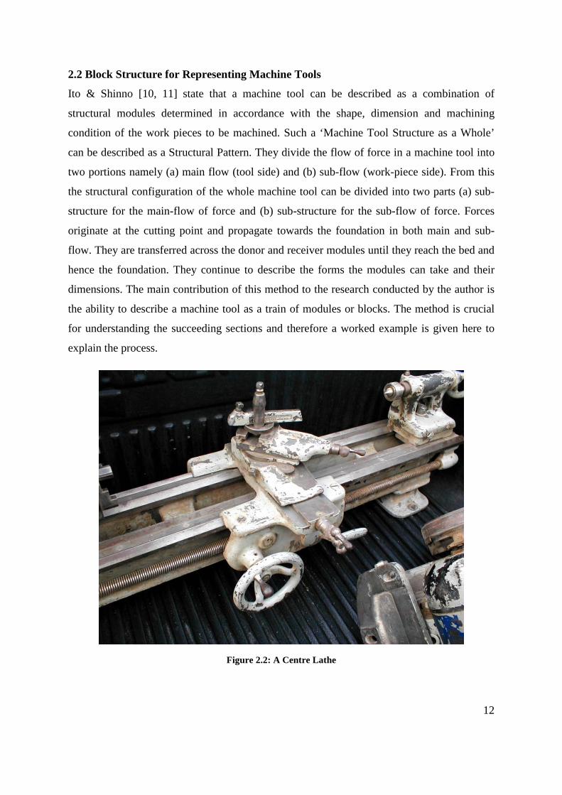
2.2 Block Structure for Representing Machine Tools
Ito & Shinno [10, 11] state that a machine tool can be described as a combination of
structural modules determined in accordance with the shape, dimension and machining
condition of the work pieces to be machined. Such a ‘Machine Tool Structure as a Whole’
can be described as a Structural Pattern. They divide the flow of force in a machine tool into
two portions namely (a) main flow (tool side) and (b) sub-flow (work-piece side). From this
the structural configuration of the whole machine tool can be divided into two parts (a) sub-
structure for the main-flow of force and (b) sub-structure for the sub-flow of force. Forces
originate at the cutting point and propagate towards the foundation in both main and sub-
flow. They are transferred across the donor and receiver modules until they reach the bed and
hence the foundation. They continue to describe the forms the modules can take and their
dimensions. The main contribution of this method to the research conducted by the author is
the ability to describe a machine tool as a train of modules or blocks. The method is crucial
for understanding the succeeding sections and therefore a worked example is given here to
explain the process.
Figure 2.2: A Centre Lathe
13
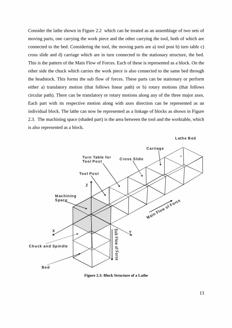
Consider the lathe shown in Figure 2.2 which can be treated as an assemblage of two sets of
moving parts, one carrying the work piece and the other carrying the tool, both of which are
connected to the bed. Considering the tool, the moving parts are a) tool post b) turn table c)
cross slide and d) carriage which are in turn connected to the stationary structure, the bed.
This is the pattern of the Main Flow of Forces. Each of these is represented as a block. On the
other side the chuck which carries the work piece is also connected to the same bed through
the headstock. This forms the sub flow of forces. These parts can be stationary or perform
either a) translatory motion (that follows linear path) or b) rotary motions (that follows
circular path). There can be translatory or rotary motions along any of the three major axes.
Each part with its respective motion along with axes direction can be represented as an
individual block. The lathe can now be represented as a linkage of blocks as shown in Figure
2.3. The machining space (shaded part) is the area between the tool and the worktable, which
is also represented as a block.
M achin ing Space
M ain Flow of Force
Sub Flow of Force
Z
YX
Bed
Turn Table forTool Post
Lathe B ed
Cross Slide
Tool Post
Carriage
Chuck and Spindle
Figure 2.3: Block Structure of a Lathe

14
Block structure can be used to represent any machine tool that would consist of a single block
to represent the workspace and numerous other blocks for the various motions performed on
the machine tool. Number of blocks used in a representative block structure would vary with
respect to number of moving and stationary parts in a machine tool.
2.3 Structural Representation in Sympathy with Block Structure Representation
Most of the work done in analysing structural layouts of machine tools has been done in the
Soviet Union. In this section some of these methods have been described. Vragov’s [5, 13]
method, which is widely cited, is described first. Portman’s [6] method of developing a
numeric code is used is discussed second. Thirdly Khomyakov and Davydov [12, 14]
proposed a code system at different levels of abstraction, which is followed by other research
like Voronovo [7] who also worked in representing the machine tool with tool and pallet
changing system.
2.3.1 Vargov’s Method
1X
Z
2
3
4
5Y
Figure 2.4: Vragov’s Method Applied to a Milling Machine
Vargov [5, 13] method uses block structure, represented using symbols to describe the
machine tool layouts. Considering the knee type milling machine shown in Figure 2.4 which
has a cutting spindle attached on one end of the structure and three moving blocks on the
other end of the fixed structure. The bed, the stationary block 4, is represent as ‘0’, whilst
three moving block 1,2,3 are represented by letters corresponding to motions of the axes
(Right hand coordinate system nomenclature) X, Y and Z respectively. The cutting spindle,

15
block 5, rotating about the Z axis is represented as C. Thus the blocks involved can be
represented as XYZOC.
The block structure not only includes information about forming and setting motion’s
direction but also number of spindles and its orientation towards work piece. Upper case
letters are used to represents forming motion and lower case letters are used for auxiliary or
setting motion. The main spindle in the knee type, milling machine is vertical to that of the
worktable, which is represented using suffix ‘v’ for vertical and ‘h’ if horizontal to the block
representing the spindle motion. More than one identical spindle is represented by numerical
digit in front of the spindle block, while parallel linking is represented by ‘+’ signs and
separated by bracket. Linking of block of motion in a machine tool is without any symbol
between them. The block carrying work piece is represented on the far left, whilst a block
carrying the tool is represented on the far right with the consecutive blocks in middle. Thus
the knee type, milling machine shown in Figure 2.4 is represented as 'XyzOCv' in Figure 2.5.
It is worth noting that motions along the Y axis and Z axis have been treated as auxiliary and
motions represented by the X and C are treated as cutting motions. The suffix v along C
indicates that the spindle is vertical.
Figure 2.5: Vargov’s representation of Xyz0Cv
Logical algebra is used to illustrate the consecutive linking of blocks as conjunction (AND
function) and parallel linking as disjunction (OR), permitting machine tool structure of any
complexity to be represented. An expression of combination of symbols thus represents (a)
the structure of the machine layout, (b) the number and type of the forming and auxiliary

16
motions, (c) the order of linking and the (d) direction of the coordinate displacement of the
blocks, (e) the distribution of elementary motions between the work piece and tool and, (f)
the type of basic layout and the design arrangement of the blocks.
Considering the gantry type, milling machine as shown Figure 2.6 consist of a worktable
connected to the base structure. Worktable performs the setting motions and has a translator
motion along Y axis, which is in turn connected rotational axis along Z. The structure further
consist of two cutting tool heads connected to structure a) to move along Z axis consisting of
five spindle and b) to move along X axis consisting or five spindle head. This can be
represented as “Yc + 0ZC5v + 0XA5h” as shown in Figure 2.7.
X
Z
Y
Figure 2.6: Gantry Milling Machine
Yc + 0ZC5v + 0XA5h
Figure 2.7: Representation of a Gantry milling machine

17
2.3.2 Portman’s Method
Portman [6] method described a machine tool using block structure and numerical symbols.
Representation of numerical symbols is in continuous chain from the worktable to the cutting
tool. The configuration is written in two stages.
The first one composes the 'code k ' for the machine tool form generating chain:
nkkkk −−= 21
In the second, the designation of the frame position is introduced
Writing the code k for the machine tool form generating chain
The code k for the machine tool form generating chain is given by
nkkkk −−= 21
Where
n is the number of moving links in the chain
1k to kn is the designation according to Table 2.3 of the motion of the first link in the form
generating chain with respect to the workpiece which is rigidly connected to the subassembly
e.g. the work clamped to the spindle of a lathe.
In this manner k is a number with as many digits as there are moving subassemblies in the
machine tool and each digit may assume value 1 to 6.
Table 2.3: Numeric Symbol representing motion
Symbol Motion with respect to preceding link 1 Translatory along the X axis 2 Translatory along the Y axis 3 Translatory along the Z axis 4 Rotatory about X axis 5 Rotatory about Y axis 6 Rotatory about Z axis
Introducing the Fixed Frame
In the code describing the configuration fixed frame are represented using '0'. In the sequence
of links from work piece to the tool if the fixed frame is the ith then introduce a '0' at the ith
position. As an example consider a centre lathe shown in Figure 2.8.

18
X
Y
Z
d
w
Figure 2.8: A Centre Lathe
The motions are (i) spindle rotation (ii) longitudinal translation of the saddle and (iii) cross
travel of the tool. Therefore 3=n , and the fixed frame or bed is after the spindle. Therefore
the lathe can be represented using the code is 6031 as shown in Figure 2.9.
6031=k
Figure 2.9: Representation of a Lathe by Portman’s method 6031
2.3.3 Method by Khomyakov and Davydov
Khomyakov and Davydov [12, 14], proposes codes at several levels of abstraction and uses.
The coordinate code described by them is comparable with other representations considered
here. The coordinate code is a set of numerical symbol of coordinate motions and in general
is of the form nl KKKK −−−= 01 .
Where lK - symbol for the lth motion.

19
n – Number of motions realised in the layout
Figure 2.10: Layout of Model IR500PMF 4 [14]
lK can have whole number values from 1 to 6; As with Portman’s method Digits 1 to 3
represent rectilinear motions along the X, Y and Z directions and 4, 5 and 6 represent rotation
relative to these axes. 0 is the divider between the tool and workpiece branches (fixed block).
Symbol lK is written with a superscript taking the values 0, 1 or 2 indicating the following:
0 – Setting motion (for example changing the tool or blank)
1 – Setting motion linked with machining (setting for machining a part with a given tool)
2 – Working motion needed for realizing the forming process.
The coordinate code thus represents the following properties of the layout:
a. Number and types of motion provided (reciprocator or rotary)
b. Orientation of the axes on or about which the motions are made
c. Sequence of the motions
d. Distribution among the tool branch and workpiece branch

20
Coordinate Code: for the machine IR500PMF 4 in Figure 2.10 is 532016 (523222 0 126110),
which represents each motion of a block is defined by a number, where in turn 1,2,3
represents the Translator motions of X, Y, Z and 4,5,6 represents rotary motions along X,Y,
Z respectively. Figure 2.11 represents the coordinate code of the IR500PMF 4. Non moving
block of the element is represented as ‘0’. Further the joints between the motions can be used
to represent them as forming or setting motions as postscripts of 2 and 1 respectively.
Table 2.4: IRM500PMF representation Code
Coordinate Code 532016 (523222 0 126110)
Block Code 800 312/201 312/101 123/101 13-2/0/101 231/602 123/501 231/900 123
Element Code 800 312/406 312/201 312/401 123/101 123 H00500/407 123/101 13 – 2 H00500/403 312/0/403 231/101 231 H00500/402 123/602 123/405 123/301 123/402 123.501
Design Code *represent’s the joint
providing motion between Y axis to X
axis
………………………………………………………………………………… 101 13-2 B:Y-1330 Z – 0695 H00500 R:00780 01145/
403 312 B:Y – 2525 Z – 0892 P070000 R:01230 00544 12245/ 0/
403 231 B:X – 0960 Y00455 Z – 0892 P070000 R:01100 00544 01920 101 231 B:X00250 Y00470 Z – 0400 H005000 R:00520 00800
………………………………………………………………………………..
Figure 2.11: Representation of IR500MPF by Khomyakov 532016 (523222 0 126110)

21
Block Code: includes further information to that of coordinate code, like a) information
consisting of position in space for the joint faces b) mounting plane and c) length of moving
joints.
Figure 2.12: Representation of IR500MPF with its mounting plane
Consider the block code from Figure 2.11 “800 312/201 312/101 123/101 13-2/0/101
231/602 123/501 231/900 123”. The code consists of pairs of numeric parts, which are
separated with a division symbol. Each pair represents a block, 800 and 900 represents the
tool and blank respectively, where the first part of the pair represents the mounting plane is
found from Table 2.5 and the next part represents the length of contact being determined by
the moving part. Figure 2.12 represents the block code of IR500MPF.

22
Table 2.5: Layout Elements [12]
Element Code: consist of further smaller and sub divided elements from block code that
constitutes a) type of joint and b) plane to which it is connected. Consider the joint 602 to
501, in particular the last block from the block code which is represented as 602 123/405
123/301 123/402 123/ 501 231 in element code from Table 2.5. The element code consists of
details of joints which are represented in two types a) ‘4’ for load carrying system; in addition
02 represents square and 05 represents cylinder and b)‘3’ for fixed system; in addition 01 for
contact in plane and 02 for cylindrical plane. The element H represents the maximum
rectilinear motion by the block in millimetre or rotation angle depending on the type of
motion.
Design code: Consist of sub-elements from the element code like, type of slide, material of
the housing, weight of the element (G), coordinate vector of the centre of gravity (b), vector
of the layout (r). Table 1 represents the part of the design code for the coordinate code of 201,
with all the sub-element details.

23
Analysis of structural layouts in sections 2.7 to 2.9 shows that the structural layout of rapidly
changing machine tools can be described as an assemblage of blocks and they can be
represented as an alphanumeric code. The codes in its simplest level can be a string of
characters. But there can be codes describing the machine tool at several different levels of
abstraction.
2.4 Structural Configuration of Machine Tools – The Design Methodology
Ito and Shinno [10, 11, 15, 16] have developed a design methodology for the modular
construction of machine tools based on the block system. It is a computer Aided system to
construct a machine tool structure as a whole integrating structural modules. It performs two
functions (a) Generating Structural Configuration and (b) Performing Structural Analysis.
The methodology described in Figure 2.13 in the form of a flow chart. The right hand side of
the flow chart shows that the movement function is the fundamental key for deciding the
number of blocks, the starting block and all other details. In the left hand side the packaging
of the modules to form a functioning machine and its rigidity related characteristics are
determined. The methodology is very much suited for the design of a modern machine tool.

24
Ha rd w are As pe ctsStru ctural Ana ly sis Flow
Softw a re Asp ec tsCo nfig ura tio n G ene ra tin g Flow
Au tom atic 3 V iew Draw ing
De te rm ina tion o f D im en sion o fStru ctural M o dule c ons id erin gStiffnes s an d The rm a l De fo rm a tion
A utom atic Pe rs pec tiv e Dra w ing
Determ ina tion o f M a chining c ond ition
Determ ina tion o f M a chining Acc uracy
Determ ination ofSpind le spe ed rang e an d Fee d ra te ra nge
De te rm ina tion o f Sh ape and Ad ja cen t fac e of s truc tu ra l m od ule co nside ring Static sCo nstraints
De te rm ina tio n of Sh ap e and D im en sion o f Struc tu ra l M o dule C ons id erin g M ac hining Spac e
Stru cturalM od uleDa ta
Se le ction an d Determ ination of Adja cen t face con side ring M o ve m ent fu nction
W ho le Structure?
De signDa ta
W ho le Structure?
Determ ination of Sta rtin g Struc tu ra l M o dule
De te rm ina tion o f Re quired M ov em e nt F unc tion
De te rm ina tion o f Total N um be r of Stru ctural M o dule s
Stru ctural M o dellingby C ubic Ele m ents
Stiffnes s Calc ulatio n
NoNo
Ye sYe s
Draw ing Da ta
Interfe re nce Che ck,Re arra nge m ent an dM od ifica tion
S im ulation ofM ov em e nt F unc tion
Re quired Fo rm G e nerating Fun ctions
Structu ral P attern
De te rm ina tion o f M a xim um W eight an d Volum e of Wo rk
De te rm ina tion o f M a chine We ig ht a nd Re quired Floo r Spac e
De te rm ina tion o f M a chining Spa ce
O utpu t:Stru ctural P atte rnPe rs pec tiv e Dra w ing3 View Draw ing
M od ifica tion o f D im en sion of ev ery Struc tura l M o dule
Sa tisfac tory Struc ture?
Proc ess or
Sa tisfac tory Struc ture?
Ye s
No
No
Ye s
Figure 2.13: Flow Chart of Ito and Shino’s Methodology

25
2.5 Chapter summary
The survey is carried out to understand the frontiers of existing technology and to formulate
the basis for work carried out in this research. Three major findings can be said as summary
of the survey:
1. Development of Machine tools started from the 18th Century were analysed under the
five categories (a) development in the processes (b) mechanical synchronisation (c)
development of cutting tools and coolants (d) early NC and automation and (e)
development of controls and controllers. These developments led to the creation of
Machining Centres capable of providing many operations in one machine. The trend
in development is seen as adding more cutting functions to make the Machine more
sophisticated. The preceding analyses led to the description of a modern machining
centre as a collection of motion-function producing elements, capable of producing
several combinations to produce the relative motions necessary for specific cutting
operations. Future developments would add more motion-functions for further
complex cuttings. Thus the code structure generated should not only be able to
describe the existing motion functions but also should be flexible to add future
addition of functions.
2. Block structure developed by the soviet scientists is seen as a useful and powerful
way of describing machine tool structures. The foundation of these methods is the
division of a Machine Tool into two sections as the main flow of forces and sub flow
or forces. Vargov represented machine tool as combination of motions, representing
each motion as a block and used Boolean algebra to represent parallel motion. Later
Voronov developed a four part coding system to represent the machine tool that
included tool and work piece changing system. Portman configured machine tool as a
numerical code based on analysis of form generation process Khomyakov and
Davydov developed a multi level coding system to describe different aspects of a
machine tool. The target uses of these codes were not clear and are not recorded in the
public domain. The developments though not complete established the hypothesis
that an Alphanumeric Code can describe a Machine Tool.
3. Shino and Ito have presented a design methodology for a Machine Tool. This
highlights that the primary step is to provide the motion functions in block structure,
which is then enhanced by structural design methods for mechanical properties. This

26
supports the view that future machines can have more blocks providing more complex
motion functions. It gives the notion that an Alphanumeric Code structure developed
should be capable of having further addition of motion functions.

27
Chapter 3 – Literature Survey – Machining
3.0 Introduction
Machining operation is possible, only when there is a machine tool and there is a work.
Machining is the production of desired geometric shapes on the surface of a finished
work piece by removing material from a raw stock. Chapter 2 investigated the Machine
Tool side of Machining. This chapter investigates the workpiece side, the machining or
creation of feature side of the operation. Computer Aided Engineering identifies Feature
Based Machining as the efficient way for handling machining operations. In this context
a feature can be visualised as a collection of basic geometric entities such as vertices,
edges, surfaces and solid lumps, which as whole gives an engineering meaning. Feature
as defined by Jami Shah [17] is a “Stereotypical knowledge structures embedded in
cognitive process in design, analysis, planning and all other engineering activities;
features are necessarily view points and application dependent”. This chapter
investigates Feature Based Machining to understand the state of the art and to integrate it
within the process of matching machines with work.
In Computer Aided Engineering a Computer model of an object is created and this master
model is used by various applications such as mechanism or motion analysis, Finite
Element Analysis, Machining planning, packaging etc. CAE packages use what is known
as a set of design features to create feature instances and a master model is an assemblage
of design feature instances present in the object under consideration. As an example
consider the object shown Figure 3.1. This has two features, a protrusion and a hole. The
master model or the design model is shown in Figure 3.1(d) as a model tree produced by
Pro/Engineer. Pro/Engineer, using the design features, has created all geometric features
describing the object. However when the machining of this component is considered
these geometric details are grouped differently into several machining features as
explained in Figure 3.2.

28
(a) (b) (c)
(d)
Figure 3.1: Creation of model in Pro/Engineer using design features
Feature 1
Feature 2
Feature 3
Feature 4
Feature 5
Feature 6
Feature 7
Feature 8
Feature 9
Feature 10
Feature 11
Feature 12
Figure 3.2: Machining Features of the Component Defined by two Design Features

29
Machining of the component requires twelve machining operations or features to be
completed. Their details can be summarised as: Features 1, 2, 3, 7: requiring removal of
rectangular volume of material, as a result of which two surfaces would be formed on the
raw stock. Features 4, 9, 10: requires removal of rectangular volume of material, as a
result of which single surfaces would be formed on the raw stock. Feature 8: requires
removal of material, which would form a semi cylindrical surface. Features 11, 12:
require removal of cylindrical volume of material, forming full cylindrical surfaces.
Similar analyses were carried out on several components and their summaries are given
in Appendix C. From the analyses it became evident that with increasing complexity of
the work-piece in high value added components, the number of machining operations
required, increased significantly. Each machining operation had its own complexity. The
steps that were considered before machining are a) Identifying Machining operations, b)
Selection and Preparation of Raw Stock, c) Grouping the Machining operations and d)
Sequencing the Machining operations. As the complexity and number of machining
operation increased, ascertaining, verifying and sequencing the machining operations
manually, became almost impossible. Also it became clear that the type of operations
performed were similar in many cases.
The task in feature based machining is to identify and define the machining features
from the design or master model described by the design feature instances. Several
researchers have developed different methods to identify machining features and
automate the identification process. For easy comprehension they can be classified into
Graph, Rule, Volume, Hint, Syntactic pattern, Template matching, Hybrid and Artificial
Neural Network based systems. In this work they are categorised into four major groups
based on the type of integration with manufacturability a) Geometry based system
providing intrinsic details of basic geometry forms b) Feature based system providing
details of pre-defined templates of features or geometry c) Application Programming
Interface systems that interact with CAD model to extract the required details and d)
various combination of the above three systems. The following sections review them.

30
3.1 Geometry Based Approaches
Solid models are described using geometric boundaries for its representation; the
boundary representation data structures can be viewed as graph structure. Graph, Hint
and Rule based can be grouped into geometry-based approach as they all use the
geometric entities within shapes such as vertices, edges and faces to identify the features.
3.1.1 Graph Matching
Boundary representation of a part can be treated as a graph structure, where faces are
considered as nodes of the graph and face-face relationships form the arcs of the graph.
The advantages of the graph representation are that there are well-established techniques
of graph algorithms easily adaptable to feature recognition.
Figure 3.1 represents a graph notation of a rectangular pocket. As seen in the Figure
3.3a, the pocket has faces 2, 3, 4, and 5 and bottom face 1. Figure 3.3b shows the
neighbourhood relationship. Node 1 is connected to nodes 2, 3, 4 and 5 representing the
connection between face 1 and the face 2, 3, 4 and 5. The line connecting nodes 2 and 3
represents the connection between the face 2 and 3. In a similar fashion the line
connecting the nodes 3 and 4, 4 and 5, 5 and 2 represents the connection between the
respective faces. The top face 6 is connected to faces 2, 3, 4 and 5 and these are
connected by line in the graph. In the similar manner the entire solid model can be
represented using a graph structure. These graphs are matched with the topological graph
structures of the predefined recognisable feature set. The features present in the solid
model can thus be identified using the graph matching.
(a) (b)
Figure 3.3: Face Relation
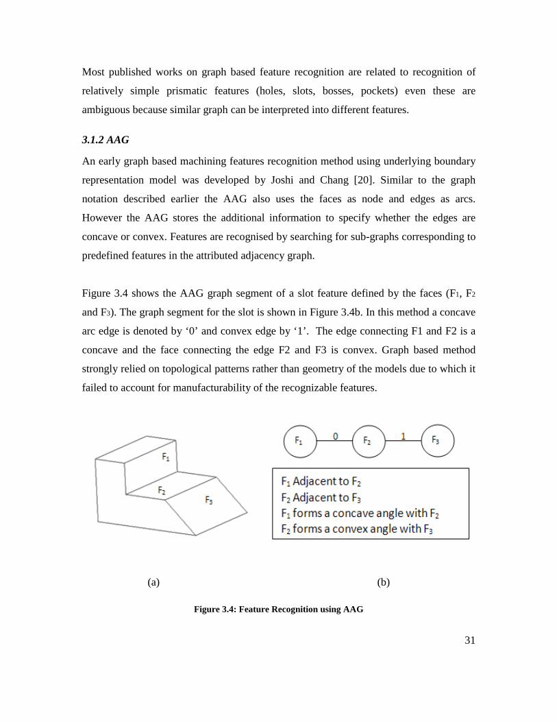
31
Most published works on graph based feature recognition are related to recognition of
relatively simple prismatic features (holes, slots, bosses, pockets) even these are
ambiguous because similar graph can be interpreted into different features.
3.1.2 AAG
An early graph based machining features recognition method using underlying boundary
representation model was developed by Joshi and Chang [20]. Similar to the graph
notation described earlier the AAG also uses the faces as node and edges as arcs.
However the AAG stores the additional information to specify whether the edges are
concave or convex. Features are recognised by searching for sub-graphs corresponding to
predefined features in the attributed adjacency graph.
Figure 3.4 shows the AAG graph segment of a slot feature defined by the faces (F1, F2
and F3). The graph segment for the slot is shown in Figure 3.4b. In this method a concave
arc edge is denoted by ‘0’ and convex edge by ‘1’. The edge connecting F1 and F2 is a
concave and the face connecting the edge F2 and F3 is convex. Graph based method
strongly relied on topological patterns rather than geometry of the models due to which it
failed to account for manufacturability of the recognizable features.
(a) (b)
Figure 3.4: Feature Recognition using AAG

32
3.1.3 EAAG
Extended attributed adjacency graph (EAAG) developed by [21] incorporated additional
information in the graph structure with respect to a) number of edges on the face, b) the
direction of the faces c) orientation of the face and d) by adding virtual link to
corresponding entities lost in interaction. This additional information aids further
processing such as recognition of interacting features. Marefat et. al., [21-23] attempted
to treat general feature interactions based on their new method called “Generated-and-test
paradigm and virtual link” concept which was extension of EAAG to include some
geometric constraints on the orientation of the feature faces. However this approach
required development of further algorithm to make it an implementable system.
3.1.4 Hint Based
Hints are geometric tracers for the presence of specific features, such as presences of an
axis indicates existence of a hole or cylindrical protrusion. In the hint-based approach,
features are built from hints by searching the boundary representation of the part. Only
hints, not full-fledged features, are found, at first and then the missing portions of the
feature are reconstructed. Meeran [24-26] used Hint and Graphed based approaches to
search for “minimal indispensable portion of feature’s boundary” called hints, rather than
complete feature. Hint based approach streamlines identification of intersecting features
by recognising the presence of one of them by the traces left behind. For example,
presence of two opposing planar faces is a hint for potential existence of a slot feature or
a thread can be hinted for hole. Vandenbrande & Requicha [27-29] also developed a hint
based feature recognition approach that undertakes the feature recognition in four steps.
Firstly feature hints are generated by searching for characteristic combinations of part
faces on the solid model, secondly the feature hints are classified into promising,
unpromising and rejected hints, thirdly the promising hints are processed by a “feature
completer” to generate the actual features, and finally a verification step is performed to
ensure that the recognised features are valid. Vandenbrande and Requicha claim that their
approach is better at recognising interacting features that earlier work couldn’t, but they
are still limited to 2.5-D swept features, and mostly prismatic parts. Hints are not

33
necessarily restricted to the part geometry. The drawback of the system was also that the
prismatic cavities were classified as pockets, resulting in machining some other feature
like T-slots as the method were partially efficient. Hint based feature recognition is quite
promising for recognizing intersecting features, but it is limited to predefined features
and hints.
3.1.5 Rule Based
Rule-based methods identify a feature, based on pre-defined rules that are characteristic
to individual features [30]. The entities expressed in the rule are typically the boundary
elements: faces, edges, loops and vertices. Constraint operators typically included
parallel, perpendicular, adjacent, equal, concave and convex relationships or conditions
that these entities must satisfy to define a particular feature. Preiss and Kaplansky [31]
developed a rule-based algorithm that identified individual cutting operations by goal-
driven search. Choi et al. [32] used pattern-matching technique to define a 3D boundary
file data structure for representing the solid model. Henderson & Anderson [33]
converted B-rep solid models and feature definitions into facts and rules of expert system.
The reasoning mechanism of Prolong searches through the facts to recognize features
according to the rules. Nnaji & Liu [34] developed a system that extracts features
relevant to assembly and machining from a CSG-based CAD system with the ability to
transform a CSG structure into a B-rep. Raymond et al. [35] presented an algorithm that
uses an octree representation of a B-rep for identifying assembly features. Their
algorithm is used to support the geometric reasoning required to locate assembly features
on disjoint bodies.
3.1.6 Summary Finding
Thus Graph, AAG, EAAG, Hint and Rule based systems used lower level geometric data
like number of edges, vertex and faces to identify partial set of machining features. These
methods were not efficient enough for complex real world parts due to extensive use of

34
Boolean operation and Artificial Intelligent (AI) languages for feature recognition.
Summarising the outcomes i) not all necessary graph links are found and at times
incorrect link [21] are identified and ii) the incorrect feature hypotheses have to be
eliminated [36]. Geometry based systems did not see much maturity; their
implementation in wide and varied domains are yet to be seen. This was due to larger
proportion of manufacturability related data, such as feature constrains, feature details,
Tool Approach Direction (TAD) and dimensional details are yet to be identified or lost in
the process. Table 3.1 summarises the capability of individual geometry based approach.

35
Table 3.1: Geometry Based Approaches
Authors
Feat
ure
Rec
ogni
tion
Met
hod
Cat
egor
y
Full
Set
of M
achi
ning
Fea
ture
s Id
entif
ied
3D fe
atur
es
2.5D
/2D
feat
ures
Parti
al S
et o
f Mac
hini
ng F
eatu
res
Iden
tifie
d
Iden
tific
atio
n of
In
ters
ectin
g fe
atur
es
Com
poun
d / A
rray
Fea
ture
s
Aut
omat
ic F
eatu
re R
ecog
nitio
n
Prim
ary
Fact
or
for
feat
ure
reco
gniti
on
Tool
App
roac
h D
irect
ion
(TA
D)
Feat
ure
crea
ted
by D
esig
n
Dim
ensi
onal
D
etai
ls
of
Mac
hini
ng F
eatu
re
Ade
quac
y C
heck
of
mac
hini
ng
feat
ure
for m
anuf
actu
ring
Inte
grat
ion
with
CA
PP
Inte
grat
ion
with
CA
M
Stan
dard
of E
xcha
nge
STEP
-224
Heu
ristic
s Alg
orith
m
Impl
emen
ted
Met
hod
Sele
ctio
n of
Ava
ilabl
e M
achi
ne
tool
s St
and
alon
e Pr
ogra
m/S
oftw
are
Inte
grat
ion
with
CA
D S
yste
m
Rep
rese
ntat
ion
of fe
atur
es
Surf
ace
Edge
s
Des
truct
ion
Synt
hesi
s
Joshi & Chang Graph G
eom
etric
Bas
ed
X X X X X X X X
Marefat and Kashyap EAAG X X X X X X X X X
Meeran Hint X X X X X X X X X X
Vandenbrande & Requicha Hint X X X X X X X X X X X
Preiss & Kaplansky Rule X X X X X X X X X
Choi et al Rule X X X X X X X X
Nnaji & Liu Rule X X X X X X X X X

36
3.2 Feature Based Approaches
Feature is a high level entity containing geometric and topologic information of the
entities (vertices, edges and faces) that form the feature. Part model is formed as an
assemble-large of feature instances. Features are application dependent as said by
Shah [17-19], like machining features, design features, and inspection feature etc.,
Machining features which is the main focus of this thesis has been defined both as
surfaces and as volumetric features.
3.2.1 Volume based
The volume decomposition approach decomposes the input model into a set of
primitive volumes and then manipulates them to identify specific features instance.
The approach is based on the idea of finding the materials that must be removed from
a raw stock to produce a part. Figure 3.5 lists the various volumes to be removed from
a stock in arriving at the end model. Kyprianou [37] initially developed the volume
based approach, using B-rep graph into hierarchical face-set data structures which
was then analysed using algorithm based on feature grammars. Kim [38] developed a
convex decomposition method for feature recognition from solid models following on
from earlier work by Kyprianou [37] and Kim et al., [38] uses a technique called
alternating sum of volumes with partitioning (ASVP) to a B-rep solid model to
recognise volumetric form features from the model. In this approach decomposing the
solid part into a hierarchical structure of convex elements, where each element
represents a volumetric feature on the part performing the feature recognition. The
main problem with volume-decomposition methods is that the operations in each step
do not guarantee success in the identification of the features, and on completion it
may not be possible to generate a feasible model totally using features.
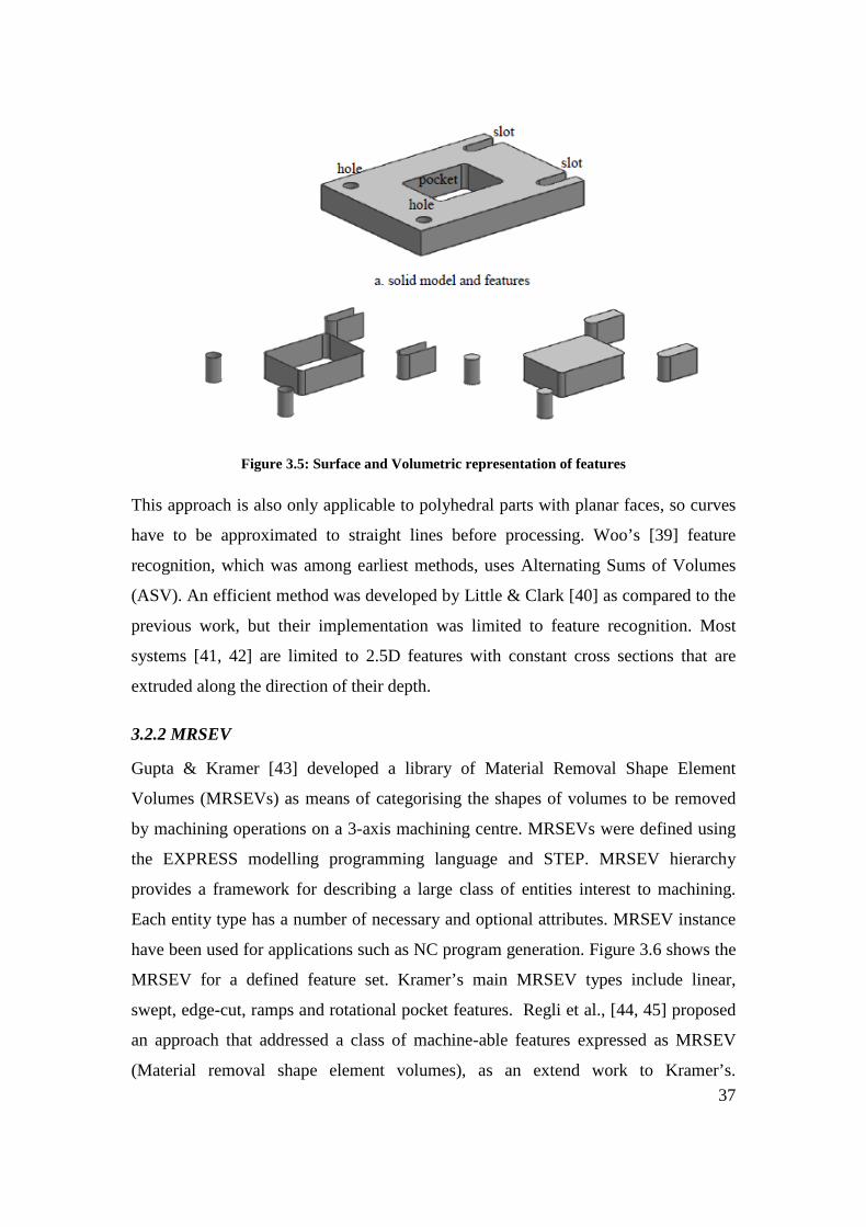
37
Figure 3.5: Surface and Volumetric representation of features
This approach is also only applicable to polyhedral parts with planar faces, so curves
have to be approximated to straight lines before processing. Woo’s [39] feature
recognition, which was among earliest methods, uses Alternating Sums of Volumes
(ASV). An efficient method was developed by Little & Clark [40] as compared to the
previous work, but their implementation was limited to feature recognition. Most
systems [41, 42] are limited to 2.5D features with constant cross sections that are
extruded along the direction of their depth.
3.2.2 MRSEV
Gupta & Kramer [43] developed a library of Material Removal Shape Element
Volumes (MRSEVs) as means of categorising the shapes of volumes to be removed
by machining operations on a 3-axis machining centre. MRSEVs were defined using
the EXPRESS modelling programming language and STEP. MRSEV hierarchy
provides a framework for describing a large class of entities interest to machining.
Each entity type has a number of necessary and optional attributes. MRSEV instance
have been used for applications such as NC program generation. Figure 3.6 shows the
MRSEV for a defined feature set. Kramer’s main MRSEV types include linear,
swept, edge-cut, ramps and rotational pocket features. Regli et al., [44, 45] proposed
an approach that addressed a class of machine-able features expressed as MRSEV
(Material removal shape element volumes), as an extend work to Kramer’s.

38
Predefined attributes were used to match and identify specific machining feature with
help of graph-based methods.
Figure 3.6: MRSEV features
Woo [46] and Huang [47] have focused on particularly domain of machining features,
using the same principles of volume based method. Li & Wang [48] considered
feature sequencing and operation sequencing which were restricted to prismatic parts
no integration towards machining. Feature based methods are efficient at dealing with
arbitrary feature interactions and generating multiple interpretations of features.
3.2.3 STEP based
Due to the nature of most neutral files such as ACIS, PARASOLID and IGES, they
only employ the boundary representation model for communication or translation
purposes between dissimilar CAD systems. Naser et al. [49] and Aslan et al. [50]
developed methods to identify machining feature from a standard data file (STL,
STEP, IGES) input and translate the information into CAM readable file with
manufacturing information. These systems lacked the ability to recognize intersecting
features due to loss of geometric data when transferred into a neutral file format.
STEP standard is a neutral file format that utilizes feature technology as they key for
file transfer and sharing. Using STEP file, data required for the NC programming
such as features details are gathered.

39
The disadvantages of feature-based method however can be summarised as follows as
shown in Table 3.2:
i) Computational complexity,
ii) Inability to generate non-convex delta machining features in some cases
iii) Inability to recognize full set of machining features
iv) Human intervention was required for intersecting features
v) Dimensional details and TAD required for machining were included
The optimistic outcomes of feature based approach was that it used
i) Volume based method,
ii) Highlighted the need for a standard data format.
iii) Research were focused towards machining features rather than general feature

40
Table 3.2: Feature Based Approaches
Authors
Feat
ure
Rec
ogni
tion
Met
hod
Cat
egor
y
Full
Set
of M
achi
ning
Fea
ture
s Id
entif
ied
3D fe
atur
es
2.5D
/2D
feat
ures
Parti
al S
et o
f Mac
hini
ng F
eatu
res
Iden
tifie
d
Iden
tific
atio
n of
In
ters
ectin
g fe
atur
es
Com
poun
d / A
rray
Fea
ture
s
Aut
omat
ic F
eatu
re R
ecog
nitio
n
Prim
ary
Fact
or
for
feat
ure
reco
gniti
on
Tool
App
roac
h D
irect
ion
(TA
D)
Feat
ure
crea
ted
by D
esig
n
Dim
ensi
onal
D
etai
ls
of
Mac
hini
ng F
eatu
re
Ade
quac
y C
heck
of
mac
hini
ng
feat
ure
for m
anuf
actu
ring
Inte
grat
ion
with
CA
PP
Inte
grat
ion
with
CA
M
Stan
dard
of E
xcha
nge
STEP
-224
Heu
ristic
s Alg
orith
m
Impl
emen
ted
Met
hod
Sele
ctio
n of
Ava
ilabl
e M
achi
ne
tool
s St
and
alon
e Pr
ogra
m/S
oftw
are
Inte
grat
ion
with
CA
D S
yste
m
Rep
rese
ntat
ion
of fe
atur
es
Surf
ace
Edge
s
Des
truct
ion
Synt
hesi
s
Kim Convex Hull Fe
atur
e B
ased
X X X X X X X X X
Kyprianou ASVP X X X X X X X X X X
Y Woo & H Sakurai
Volume Decomposition X X X X X X X X X
G Little, DER Clark et al
Delta Volume Decomposition X X X X X X X X X
Kramer MRSEV X X X X X X X X X
Regli and Nau MRSEV X X X X X X X X X X
Z Liu & L Wang
Machining Feature X X X X X X X X X X X
Naser et al STEP X X X X X X X X X X
Aslan et al STEP X X X X X X X X X X

41
3.3 Application Programming Interface Approaches
Application Programming Interface (API) picked up movement with development in CAD
system, providing application interface to retrieve the required data from the CAD Design.
This provided easy interface for features recognition methods. In API platform-dependent
approach, both the creation of the CAD model and the feature recognition are done in the
same CAD platform. Individual design feature information is obtained via programming in
the API provided by the CAD modeller. The advantages of API approach are, a) Easy access
to generic features in the library, b) ability to retrieve geometry and topology data of the
specific feature instances, c) Exploitation of the built in functions (API) from within the solid
modeller to facilitate the application of the feature recognition rules.
Lee & Kim [51] extracted machining features data from a feature-based CAD model, which
was based on an integrated geometric modelling approach system that supported both
feature-based modelling and features recognition. Lee and Kim presented an approach for
incrementally extracting machining features from a feature based design model as a design
progress. The proposed approach utilizes both feature and geometric information of the
feature instance for feature mapping. Hence it works well for mapping design features,
including protrusion, transition and interacting features, into machining features. Interacting
features can be effectively handled by the generic naming scheme that manages all the
merged and split faces
Here the system is capable of handling the majority of complex features, however due to high
dependence on the design driven approach, it was not successful in extracting all application
specific features domains. Woo and Sakurai [46] presented a system for recognizing a set of
machining (or maximal) features in a designed part. This was done by decomposing the delta
volume, which was the machine-able volume from the stock in arriving at the part. Huang et
al. [47, 52] studied the decomposition and combination of delta volumes for converting
features. Their efforts exploited the robustness of the platform-dependent tools in solving the
problems.
Li et al. [53] proposed a methodology for recognizing manufacturing features from a design-
by-feature solid modeller. They analysed design feature’s using 2D profile to convert into

42
manufacturing features. The limitations of their work were due to the difficulty in creating
2D profiles for complex features. Sadaiah et al. [54] identified the feature as the input for the
computer-aided process planning (CAPP). This system records individual feature information
of models designed in SolidWork, a 3D CAD modeller. In this research, the designer’s
interaction with the solid modeller was reflected into a text file.
The syntactic pattern recognition approach uses the semantic primitives for part analysis. The
structured information is used to create a description and a classification of the part.
Arivazhagan, et al. [55] developed Machine-able Volume Identifiers (MVI) and used
syntactic pattern strings stored in database to check the generated strings of the features. This
covered only feature like Step (through, blind & with corner conditions), Slot (through, blind
& with corners conditions), Pocket (Through, blind & corner conditions), Hole and Chamfer;
further details required for machining was not implemented.
Projective feature developed by Lee et al. [56] felt the need for precedence relation among
features from CAD depending on the location of the feature and its machining restrictions.
This was a development of Tseng & Joshi’s [57] approach using API; the outcome was
limited to 2.5D features. This method was focussed towards the process-planning algorithm
and not towards machining.
Prabhakar & Henderson [58] were the pioneers in using neural network based feature
recognition algorithms in feature recognition. The input to the system is a face adjacency
matrix, which consists of relationships between faces, with each row of matrix containing
information related to a face. The two major characteristics of Neural Network are learning
and recalling. Learning is the process of adjusting the connection weights to produce the
desired output. Recall is the process of providing an output for a given input in accordance
with neural weight structure. The application of Neural Network Based feature recognition
has some conflicts due to interacting features such as blind slots and non standard type
features. This is due to face adjacency matrix not containing all geometric information to
define the features of same topology.

43
Artificial Neural Network (ANN) based feature recognition techniques were developed by
Ding & Yue [59] and various other researchers [58, 60-62]. ANN techniques have become
advantageous because they reduce some drawbacks like limited feature recognition and
additional heuristic rules need of that of geometry and feature based systems. However ANN
based systems are not matured enough to identify the entire machining features, but have the
capabilities to identify geometrical and manufacturing information such as feature class,
dimension & tolerance, TAD and feature relationships.
API and ANN approaches identified the user-defined features, but did not meet the basic
need for feature recognition towards integration of CAD/CAM. The major drawbacks of the
API based systems can be summarised as shown in Table 3.3:
i) Input representation of features were ambiguous
ii) Features were not unique and
iii) Large size of matrix to define a features restrict the capability of computing
Due these drawbacks they were considered non effective and non efficient in many instances.
API programming eliminated most problems encountered by previous methods. However it’s
lack of ability to identify intersecting features and ambiguity of input representation limited
its application. It also failed to cater the full requirements of a machining process, lacking in
vital information needed, such as feature class, feature interaction, dimensions and tool
approach direction. Though API is in forefront of present research work in identifying
machining features from a CAD based system, the elimination of its drawbacks will project it
as a viable alternate.

44
Table 3.3: Application Programming Interface Approaches
Authors
Feat
ure
Rec
ogni
tion
Met
hod
Cat
egor
y
Full
Set
of M
achi
ning
Fea
ture
s Id
entif
ied
3D fe
atur
es
2.5D
/2D
feat
ures
Parti
al S
et o
f Mac
hini
ng F
eatu
res
Iden
tifie
d
Iden
tific
atio
n of
In
ters
ectin
g fe
atur
es
Com
poun
d / A
rray
Fea
ture
s
Aut
omat
ic F
eatu
re R
ecog
nitio
n
Prim
ary
Fact
or
for
feat
ure
reco
gniti
on
Tool
App
roac
h D
irect
ion
(TA
D)
Feat
ure
crea
ted
by D
esig
n
Dim
ensi
onal
D
etai
ls
of
Mac
hini
ng F
eatu
re
Ade
quac
y C
heck
of
mac
hini
ng
feat
ure
for m
anuf
actu
ring
Inte
grat
ion
with
CA
PP
Inte
grat
ion
with
CA
M
Stan
dard
of E
xcha
nge
STEP
-224
Heu
ristic
s Alg
orith
m
Impl
emen
ted
Met
hod
Sele
ctio
n of
Ava
ilabl
e M
achi
ne
tool
s St
and
alon
e Pr
ogra
m/S
oftw
are
Inte
grat
ion
with
CA
D S
yste
m
Rep
rese
ntat
ion
of fe
atur
es
Surf
ace
Edge
s
Des
truct
ion
Synt
hesi
s
Lee & Kim Feature Based A
pplic
atio
n Pr
ogra
m In
terf
ace
X X X X X X X X
Woo &Sakurai Machining X X X X X X X X
Le et al Design by Feature X X X X X X X X
Huang et al. Decomposition X X X X X X X X
Sadaiah et al Feature X X X X X X X X X
Arivazhagan, et al MVI X X X X X X X X X
Tseng & Joshi Precedence X X X X X X X X
Prabhakar & Henderson Neural Network X X X X X X X X X
Ding & Yue ANN X X X X X X X X

45
3.4 Combination or Hybrid Approaches
Hybrid methods are based on combination of Geometry, Feature and API based methods to
meet the challenges encountered in recognizing interacting features from a CAD model.
Marefat et al [21-23, 63] introduced a different hint-based approach, significantly extending
the classical graph-based approach to include uncertainty reasoning to avoid the
computational complexity that results from sub-graph isomorphism. In addition to face Ids,
the graph nodes contain information about their relative orientation and edges represented as
links contain concavity information. The cavity graphs of the part are extracted and
partitioned for, sub-graphs to be compared with existing feature templates for isomorphism.
If the sub-graphs cannot be verified, they are further analyzed for evidence by adding “virtual
links”. The Dempster-Shafer theory is utilized for uncertainty reasoning to provide the most
probable virtual links. Gao & Shah [36] used a Minimal Condition Sub-graph (MCSG) for
their reasoning. This is achieved by extending the classical attributed adjacency graph (AAG)
to create the Extended AAG (EAAG) in which both the faces (nodes) and edges (links) carry
extra information. Face attributes such as whether they belong to the stock or part, are Unifi-
able or not, are part of the convex hull or not, how many loops they have and their geometry
like vertices and faces are used as inputs. Edge attributes such straight or curved, be part of
the inner or outer loop of a face, smooth or sharp, in addition to being convex or concave,
and real or virtual are taken into consideration.
Manufacturing Face Adjacency Graphs (MFAGs) are readily recognized by eliminating stock
and convex hull faces. Partial patterns are called MCSGs and are treated as hints that need to
be completed via addition of virtual links. Reasoning for virtual links is done by dividing
feature interactions into six types, thus making it possible to generate multiple interpretations
by completing the graphs in alternative ways. Another method that modified the AAG
technique using hint based reasoning was introduced by Ibrahim and McCormack [64, 65].
Similar to Gao & Shah [36] approach, this technique increased the attributes of both edges
and faces; however the resulting AAG, called a Modified Attributed Adjacency Graph
(MAAG), was not broken down into sub-graphs. Instead, features are grouped into “families”
according to hints generated by “part surfaces“, which must be in constant contact with the
tip of the cutting tool which machine them. Seeking out faces with at least one concave edge

46
identifies part surfaces. For each such face adjacent faces with convex edges are retrieved,
thus creating an opening for that face. Special cases include through features, with no part
surface, and protrusions with associated surrounding part surfaces. New feature taxonomy is
created based on hints from the MAAG classifying features such as simple depressions,
protrusions, passages and multi-part surfaces. This work is further explained by Ibrahim and
McCormack [64, 65], and comes closest to hint-based reasoning among the approaches
mentioned in this subsection.
A hybrid method based using feature hints, graph theory and artificial neural network was
proposed by Li, Ong & Nee [66]. Modified AAG and API were used by Zhang et al. [67].
Volume subtraction and face adjacency graph method was proposed by Rameshbabu &
Shunmugam [68, 69]. Hint based and Rule based systems are utilized by Dimov et al. [70]
for feature recognition. Pal & Kumar [71] used feature algebra by Karinthi [72] combined
with heuristic rules to identify features. Each hybrid approach has proven to be effective in
recognizing interacting feature due their robustness and strong learning capability. Each
approach is effective in certain subtask of the interacting feature recognition process with
optimum efficiency; however satisfactory results cannot be achieved using a single method.
Extracting a complete set of machining features and their details were still not achieved.
Most systems use low-level features that are predefined in the CAD system’s libraries. But
higher-level features are more convenient to express the parts, domain specific functionality
and machining characteristics. In a hybrid approach, it is assumed that all machining features
can be machined in a single machine centre. Most components require multiple machining
centres [47] to achieve intricate machining details. In most cases the subsequent machining
details such as machine tool selection, operation selection, operation sequencing and
machining sequencing were not considered.

47
Table 3.4: Combination or Hybrid Approaches
Authors
Feat
ure
Rec
ogni
tion
Met
hod
Cat
egor
y
Full
Set
of M
achi
ning
Fea
ture
s Id
entif
ied
3D fe
atur
es
2.5D
/2D
feat
ures
Parti
al S
et o
f Mac
hini
ng F
eatu
res
Iden
tifie
d
Iden
tific
atio
n of
In
ters
ectin
g fe
atur
es
Com
poun
d / A
rray
Fea
ture
s
Aut
omat
ic F
eatu
re R
ecog
nitio
n
Prim
ary
Fact
or
for
feat
ure
reco
gniti
on
Tool
App
roac
h D
irect
ion
(TA
D)
Feat
ure
crea
ted
by D
esig
n
Dim
ensi
onal
D
etai
ls
of
Mac
hini
ng F
eatu
re
Ade
quac
y C
heck
of
mac
hini
ng
feat
ure
for m
anuf
actu
ring
Inte
grat
ion
with
CA
PP
Inte
grat
ion
with
CA
M
Stan
dard
of E
xcha
nge
STEP
-224
Heu
ristic
s Alg
orith
m
Impl
emen
ted
Met
hod
Sele
ctio
n of
Ava
ilabl
e M
achi
ne
tool
s St
and
alon
e Pr
ogra
m/S
oftw
are
Inte
grat
ion
with
CA
D S
yste
m
Rep
rese
ntat
ion
of fe
atur
es
Surf
ace
Edge
s
Des
truct
ion
Synt
hesi
s
Gao & Shah MCSG H
ybrid
X X X X X X X X X
Ibrahim & McCormack MAAG X X X X X X X X X
Li, Ong & Nee X X X X X X X X X
Zhang et al X X X X X X X X X
Rameshbabu & Shunmugam Hybrid X X X X X X X X X X X X X
Dimov et al X X X X X X X X
Pal & Kumar X X X X X X X X X X

48
A summary of all the feature recognition approaches with their major merits and demerits
with respect to machining capability are given summarized on each section. A substantial
knowledge has been generated in this area. The major hurdle however with all these
recognition techniques is that they do not consider a complete set. In addition the intersecting
features have not been given adequate consideration. These are the missing links in total
integration of CAD to CAPP and CAM.
International Standard Organisation developed ISO 10303-224 for describing machining
features as included in Appendix I, which primarily focused towards defining machining
features with intrinsic details. However the details covered are too extensive for the purpose
of identifying a matching machine tool.
Adequacy of machining features was first established by Chitroda & Sivaloganathan [73],
using the machining feature set provided by the Expert Machinist module of Pro/Engineer.
Expert Machinist is a feature based machining (milling) software bolted on to the
Pro/Engineer (CAD software) to simulate and create downwards activities in milling
application. Chitroda & Sivaloganathan considered fifty different machining components and
established that the machining feature set provided by Expert Machinist is adequate to define
any machining job. Srikumaran [74] had used feature mapping technique for identifying
manufacturability of components using expert machinist feature set which can be used as
early as design stage [75]. However PTC has withdrawn Expert Machinist thus forcing the
development of an adequate feature set. Adequacy of the new Machining Feature set would
be automatically established if the new set can replicate the features provided by Expert
Machinist. Such a new set of machining features is proposed in this thesis and is described in
the following section.
3.5 Surfaces and Surface Parameters Characterising Machining Features
Machining features are characterised by surfaces and each surface has its own parameters.
Machining features and their constitutive surfaces are discussed below.
3.5.1 Step Feature
Step features is created by two plane surfaces from the workpiece S1 and S2 as shown in
Figure 3.7, both the surfaces continuously join together to form a V between them, the step
features parameters can be identified from the surfaces.

49
Figure 3.7: Step Feature
Orientation of the features depends on normal vector of the bottom surface S1, length and
width are identified from surface extremes. Depth of the step feature is identified using the
plane surface S2 and its surface extremes. Figure 3.8 illustrates the two surfaces that create
the step feature.
Figure 3.8: Surface Creating the Step Feature
3.5.2 Slot Feature
Slot Feature consists of three surfaces, S1, S2 and S3 from the workpiece of which two
surfaces S2, S3continuously joined with S1. Depending on the surface a) if S1 and S2 can be
parallel or inclined to each other as shown in Figure 3.9(a) is called as through slot and b) S1
and S2 are connected continuously to each other also as shown in Figure 3.9(b) is called as
open slot.

50
Figure 3.9: Slot Feature
Parameter of the slot features can be identified from the surfaces S1, S2 and S3, orientation of
the slot depends on the bottom surface S1, length, width can also be identified from the plane
surface S1’s surface extremes. The depth of the slot feature is identified from the plane
surface S2 or S3 from its surface extremes. Various parameters of the slot feature and the
three surfaces creating the slot feature is illustrated in Figure 3.10.
(a)
(b)
Figure 3.10: Parameters of a Slot Feature
3.5.3 Round Feature
Round Feature consist of single cylindrical surface S1 as shown in Figure 3.11.

51
Figure 3.11: Round Feature
Parameters of the round feature such as its orientation, dimensions are identified from the
cylindrical surface S1 and its surface extremes as shown in Figure 3.12.
Figure 3.12: Parameters of Round Feature
3.5.4 Planar Feature
Planar feature is made up of a single plane surface S1 from the workpiece as shown in Figure
3.13(a), some time the surface might consist of contour or island called as boss as illustrated
in Figure 3.13(b).

52
Figure 3.13: Planar Feature
Parameters of the planar feature such as its orientation, dimensions are identified from the
plane surface and its surface extremes as shown in Figure 3.14.
Figure 3.14: Parameters of Planar Feature
3.5.5 Chamfer Feature
Chamfer feature is made up of a single plane surface S1 from the workpiece as shown in
Figure 3.15.

53
Figure 3.15: Chamfer Feature
Parameter of a chamfer feature such as its orientation, dimensions are identified from the
plane surface S1 and its surface extremes as shown in Figure 3.16.
Figure 3.16: Parameter of Chamfer Feature
3.5.6 Hole Feature
Hole features is made up of two cylindrical surface called as through hole, or two cylindrical
and one plane surface blind hole from the workpiece. Figure 3.17 illustrates different kinds of
holes, a) if the cylindrical surfaces are parallel to each other they are straight hole and b) if
the cylindrical surfaces are inclined they are conical holes.

54
Figure 3.17: Hole Features
Parameters of a hole feature such as its orientation, dimensions are identified from the plane
surface in absence the cylindrical surface is used and its surface hole features surface
extremes are shown in Figure 3.18.
Figure 3.18: Parameter of Hole Feature
3.5.7 Pocket Feature
Pocket features is of three types a) through pocket which consist of four plane surfaces from
the workpiece of which pair of surfaces are parallel to each other, b) five plane surface of
which two sets are parallel to each other and these are connected to the fifth surface as shown
in Figure 3.19(a) and c) b) four plane surfaces from the workpiece of which two planes are
paralle1 and other two are perpendicular to each other as shown in Figure 3.19(b).

55
(a)
(b)
Figure 3.19: Pocket Feature
Parameter of the pocket features can be identified from the surfaces S1, S2, S3 and S4,
orientation of the slot depends on the bottom surface S5 in absence its identified from the S1
or S2 surface, length, width can also be identified from the plane surface S5’s surface
extremes. The depth of the slot feature is identified from the plane surface S1 or S2 from its
surface extremes. Various parameters of the pocket feature and the plane surfaces creating the
slot feature is illustrated in Figure 3.20.

56
(a)
(b)
(c)
Figure 3.20: Parameters of a Pocket Feature
This section thus highlights the geometric properties that are needed to analyse any
manufacturing feature. A lot of research work has been done [15], [17], [21], [27] on feature
definition and recognition methods, but their adequacy has never been checked. Chitroda and

57
Sivaloganathan [73]. have established that Expert Machinist features are adequate for
describing all machining operations performed in a Vertical Machining Centre. But
Pro/Engineer does not permit access to these machining feature parameters. A machining
feature set whose parameters are accessible was needed to achieve the objectives of the
research. Since the feature set provided by Expert Machinist was proven to be adequate a set
that can map all features in Expert Machinist has been developed. It is created to make bolt-
on to Pro/Engineer. Section 3.7 describes them.
3.6 Cuts as Machining Features and their Characteristic Surfaces and Parameters
The high level modelling entities of feature-based design can provide the necessary
information needed by applications to store and retrieve information of a particular feature.
Geometry issues depend on the feature creation methods supported by the modeller. The
classification of design features may vary for different solid modellers. Various design
features available in Pro/Engineer are;
• Protrusion • Cut • Chamfer • Hole
• Round • Rib • Shell • Pipe
The primary feature creation methods in part modelling are protrusions (mass additions) and
cuts (mass removal). Protrusions and cuts are created using 2-D cross sections that are
extruded, revolved, swept or blended in creating the required shapes. As machining is the
process of material removal, so a base is created as a protrusion considering as raw stock and
further cuts are added on to raw stock. The various cuts creating the machining features are
described below;
3.6.1 Step Feature
The Figure 3.21 illustrates the creation of a step feature using the design feature cut in
Pro/Engineer. 2D sketch is drawn as highlight in red colour such that the corner of the
drawing

58
Figure 3.21: Step Feature
coincides with that of the workpiece. The sketch is then swept across in the direction of the
arrow to create the cut to the full length, the material removed as this process is highlighted in
green. The material removed would created two plane surfaces which would form a V shape
between them to form the step feature
3.6.2 Slot Feature
The Figure 3.22 illustrates the creation of a slot feature using the design feature cut in
Pro/Engineer.
(a)

59
(b)
Figure 3.22: Slot Features
2D sketch is drawn as highlight in red colour such that the top end of the drawing coincides
with that of the workpiece. The sketch is then swept across in the direction of the arrow to
create the cut to the full length for through slot as shown in Figure 3.22(a). Open slot is
created with a 2D sketch that coincided to the corner of the workpiece and swept to a limited
distance and not throughout as shown in Figure 3.22(b). Outcome of the design process
would result in material removed as highlighted in green. The material removed would create
three plane surfaces which would form the slot feature.
3.6.3 Round Feature
The Figure 3.23 illustrates the creation of a round feature using the design feature round in
Pro/Engineer. The edge on which the round has to be created is selected as highlight in red
colour, and the radius for rounding is designated. The outcome of the design process in
Pro/Engineer will result in removal material from the base to create a single cylindrical
surface on the edge selected as shown in Figure 3.23.

60
Figure 3.23: Round Feature
3.6.4 Planar Feature
The Figure 3.24 illustrates the creation of a planar feature using the design feature cut in
Pro/Engineer. 2D sketch is drawn as highlight in red colour such that the outline of the
workpiece coincides with that of the drawing. The sketch is then swept across in the direction
of the arrow and swept to a limited distance and not throughout as shown in Figure 3.24(a).
Creation of a small island of material within the process creates the bosses as shown in Figure
3.24(b) Material removed as this process is highlighted in green. The material removed
would create single plane surface which would form the planar feature.
(a)

61
(b)
Figure 3.24: Planar Feature
3.6.5 Chamfer
The Figure 3.25illustrates the creation of a Chamfer feature using the design feature chamfer
in Pro/Engineer. The edge on which the chamfer has to be created is selected as highlight in
red colour, and the angle and length of the chamfer is designated. The outcome of the design
process in Pro/Engineer will result in removal material from the base to create a single plane
surface on the edge selected as shown in Figure 3.25.
Figure 3.25: Chamfer Feature

62
3.6.6 Hole
The Figure 3.26 illustrates the creation of a Chamfer feature using the design feature hole in
Pro/Engineer. The surface on which the hole has to be created is selected and referenced, the
hole diameter is designated if its straight hole as shown in Figure 3.26 or a conical hole is
sketched. The outcome of the design process in Pro/Engineer will result in removal of
material from the base to create a two cylindrical surface for through hole and a two
cylindrical and a plane surface for a blind hole.
Figure 3.26: Hole Feature
3.6.7 Pocket
The Figure 3.27 illustrates the creation of pocket feature using the design feature cut in
Pro/Engineer. 2D sketch is drawn as highlight in red colour such that the sketch is within the
workpiece. The sketch is then swept across in the direction of the arrow to create the cut to
the full length for through pocket as shown in Figure 3.27(a) and blind pocket is created with
limited distance as shown in Figure 3.27(b). Open pocket is created with a 2D sketch that
coincided to the edge of the workpiece and swept to a limited distance and not throughout as
shown in Figure 3.27(c). Outcome of the design process would result in material removed as
highlighted in green. The material removed would create a) four plane surfaces for open and
through pocket and b) five plane surfaces for a blind pocket.

63
(a)
(b)
(c)
Figure 3.27: Slot Feature
3.7 Chapter Summary
The survey on Machining has been carried out to understand Machining Process and the
modelling approach (Machining Feature approach) taken to model them. The following can
be said as the summary of the survey.

64
• There exists a class of components which can be classified as high value added
components and they are more suited for CADCAM software based coding for the
generation of their NC code.
• Analysis of the machining of some typical components led to the understanding of the
need and opportunity for Machining Feature based approach.
• Survey showed the two major sets of Machining Features, one developed by ISO and
one developed by Expert Machinist.
• Since machining process is about producing surfaces, surface parameters for the
production of these features have been studied.
• A cut-based feature set has been developed to model machining.

65
Chapter 4: Methodology
4.0 Introduction
The broad aim of this research work was to develop a systematic methodology to choose a
machine tool, by matching feature complexity of machining job presented to that of machine
tool. This involved the integration of two main groups of considerations (a) the machine tool
and its capabilities and (b) the required component and the raw stock.
Survey of literature reveals that an Alphanumeric Code can be adequately employed to
represent a machining centre and machining features can be employed to represent a
machining job. The work started with the machining features provided by Expert Machinist
but after its withdrawal a new set similar to it was needed. A new set mimicking the features
provided by Expert Machinist has been developed.
The methodology adopted here can be summarised as “generate an alphanumeric code for a
given machining job and draw matching machine tools using this code from a database of
machine tools which uses similar alphanumeric codes as the sorting field. A choice can then
be made by the user for a particular machine tool. The methodology adopted to carry out
this work is shown as a flow chart in Figure 4.1

66
Figure 4.1: Flow Chart Showing the Methodology
The left hand side of the flow chart outlines considerations from the component and its raw
stock, to generate an alphanumeric code of the component to be machined with the required
accuracy. The right hand side of the flow chart demonstrates the processing of the
information about Machine Tools and stores them in a database. The data can be browsed and
selected using the alphanumeric code of the component. The alphanumeric code thus acts as
the link between the two groups of information. Once a list of suitable machine tools is
established the user can choose the machine tool that he prefers. The following subsections
explain the activities carried out in each of the arm in the methodology outlined in the flow
chart.

67
4.1 Analyze and establish essential features of a Machining Centre
4.1.1 Background
BS4656-30 defines a Machining Centre as a numerically controlled machine tool capable of
performing a variety of operations at one set-up of a workpiece (normally two or more of
turning, boring, drilling, milling and screwing and threading) and able to select and change
tools, position the workpiece and the cutter, and control speeds and feeds and ancillary
services (e.g. coolant flow).
BS4656-30 [76] outlines combinations of axes configurations that are possible and they are
given in Appendix H. Research work by Vragov, Protman, Davydov, Voronov and Ito on
Structure and Coding of NC Machine Configurations have proceeded along developing codes
showing the motion of load carrying system. The question however is, what are the details
that have to be provided by the code. Research publications did not help much. Sales
brochures produced by machine tool manufacturers are the prime sources of information for
precision engineering companies to base their choice of machine tools. Therefore the
information provided in the sale brochures should be sufficient to make the choice. An
analysis of the sales brochures was chosen as the method to identify the features to be
included in the code. Section 4.1.2 describes the work carried out.
4.1.2 Analysis of Information about Machine Tools in the Market
Sales brochures provided by machine tool manufacturers are aimed at potential users and
they provide vital information, which in the opinion of the company are the factors that
would sway the decision towards the purchase of the machine. For example consider the
information provided by DUGARD machine tools about their Vertical Machining Centre 660
in Appendix G. The information given includes basic details consisting of the traverse
motions, number of tool and tool changer, spindle speed and the type of controller. Further
information regarding options of spindle, machine structure, capacity, weight and lubrication
are given in the next section of the broacher. This enables user to get a closer understanding
that the machine tool can offer for machining. Finally any additional features which are
optional on the machine tool are provided for the user to add on to existing model of machine
tool, if required. Machine tool brochures by Haas gives further details about their rigid body
structure, motion controls, spindle features, coolant, chip removal, and other conveniences

68
like Dust removal and M-Functions individually. The brochures also consist of details and the
differences between their own models to differentiate as a matrix so the user can identify the
required feature that might be present with the model of interest.
Sale brochures from manufacturers for thirty nine machine tools of different sophistication
were analyzed and the summarised analysis is given in Table 4.1. The columns indicate the
information element and the rows indicate the machine tool models considered.

69
Machine tool Model Fe
atur
es
X T
rave
rse
Y T
rave
rse
Z Tr
aver
se
a ro
tatio
n
b ro
tatio
n
c ro
tatio
n
Wk
Tab
Load
Cap
acity
T Sl
ots o
n W
ork
Tabl
e
Chu
ck o
n W
ork
Tabl
e
Rap
id T
rave
rse
Acc
urac
y
Rep
eata
bilit
y
Aut
o. T
ool C
hang
er
Tool
Mag
azin
e
Aut
o. P
alle
t Cha
nger
Con
trolle
r
USB
/ Eth
erne
t/ H
D In
terf
ace
Off
line
con
trol
Expa
ndab
le m
emor
y
Spin
dle
Spee
d
Spin
dle
feed
S.ta
p B
T/C
AT/
HK
/SH
K
Spin
dle
Tw/ S
pead
Gea
r box
Coo
lant
Sys
tem
Thr.
Spdl
e C
oola
nt
Coo
lant
filte
r
Swar
f Rem
oval
Dus
t Ext
ract
ion
Syst
em
Gua
rd
Elec
troni
c ha
nd w
heel
Tool
and
Par
t Pro
bing
Add
ition
al M
Fun
ctio
ns
Mac
hine
Wei
ght
Haas TM series Haas MM series Haas VF 1 Haas VM 2 & 3
Haas VR 8 & 9
Haas VS 1
Haas EC - 400
Haas GR 512
Ajay AJVMC series
Ajay AJUBM series
Ajay AJVTL series
Cincinnati CFV5 series
Cincinnati CFV series
Cincinnati NBH series
Cincinnati FTV series
DMG DMC 60H & 80H
DMG 55, 75, 105V
DMG DMU 60T
DMG 635V, 835V
DMG 50eVo, 70eVo
DMG DMU 60, 80, 100P
Table 4.1: Machine Tool Analysis

70
Table 4.1 Machine Tool Analysis (Continued)
Machine tool Model Fe
atur
es
X T
rave
rse
Y T
rave
rse
Z Tr
aver
se
a ro
tatio
n
b ro
tatio
n
c ro
tatio
n
Wk
Tab
Load
Cap
acity
T Sl
ots o
n W
ork
Tabl
e
Chu
ck o
n W
ork
Tabl
e
Rap
id T
rave
rse
Acc
urac
y
Rep
eata
bilit
y
Aut
o. T
ool C
hang
er
Tool
Mag
azin
e
Aut
o. P
alle
t Cha
nger
Con
trolle
r
USB
/ Eth
erne
t/ H
D
Inte
rfac
e O
ff li
ne c
ontro
l
Expa
ndab
le m
emor
y
Spin
dle
Spee
d
Spin
dle
feed
S.ta
p B
T/C
AT/
HK
/SH
K
Two
Spea
d G
ear b
ox
Coo
lant
Sys
tem
Thr.
Spdl
e C
oola
nt
Coo
lant
filte
r
Swar
f Rem
oval
Dus
t Ext
ract
ion
Syst
em
Gua
rd
Elec
troni
c ha
nd w
heel
Tool
and
Par
t Pro
bing
Add
ition
al M
Fun
ctio
ns
Mac
hine
Wei
ght
Dugard Eagle 660 Dugard Eagle 450XP+ Dugard Eagle 850 Durgard Eagle X5 Hardinge VMC XR series Hardinge VMC 500AX Hardinge XR APC Hardinge XR HPC Hardinge XV series Hurco VM series Hurco VMX series Hurco VTXU Hurco VTXV Hurco HTX Mazak FH series Mazak FJV series Mazak HCN series Mazak VCN series Required Features

71
4.1.3 Choice of Information Needed to be Incorporated into the Code
Preceding analyses identify the important features that need to be considered for selection of
a machine tool by an end user i.e. the precision engineer. However all these features are not
needed for an outsourcer for example number of T slots. The identified features are (a)
traverse and rotary motions (b) automation, (c) cutting tool, (d) spindle performance (e)
fixtures (f) accuracy (g) repeatability (h) Controllers and (i) presence of cooling system, dust
& swarf removal system are only considered.
Traverse and Rotary motions are two major type of motion that can be carried out by the
machine tool, which would be used for setting and forming of the component.
Automation would represent the speed at which the component can be loaded using APC and
cutting tool can be changed using ATC to reduce time of machining.
Number of cutting tool is necessary for a high value added component when the machining
might require more than one cutting tool to reduce the number of setup.
Spindle performance like there speed and feed are necessary for removing material,
depending on the component.
Fixture: Components are needed to be held in proper orientation using fixture for the cutting
tool to approach the component for machining.
Accuracy and repeatability depend on the slide-ways and the motor which enable the traverse
and rotary motions to be executed with minimum error.
Controllers: Motions and cutting parameters are managed by controllers
Other Functions: to aid the machining process cooling, dust and swarf removal system are
needed.
4.2 Analyzing Individual Features and Establish them as Alphanumeric Strings
Each of the machining feature identified in section 4.1.4 are essential for a precision engineer
to select appropriate machine tool for a job. The representation of these features as
alphanumeric strings is discussed in this section.
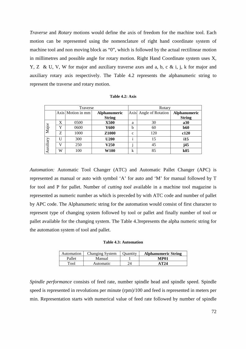
72
Traverse and Rotary motions would define the axis of freedom for the machine tool. Each
motion can be represented using the nomenclature of right hand coordinate system of
machine tool and non moving block as “0”, which is followed by the actual rectilinear motion
in millimetres and possible angle for rotary motion. Right Hand Coordinate system uses X,
Y, Z & U, V, W for major and auxiliary traverse axes and a, b, c & i, j, k for major and
auxiliary rotary axis respectively. The Table 4.2 represents the alphanumeric string to
represent the traverse and rotary motion.
Table 4.2: Axis
Traverse Rotary Axis Motion in mm Alphanumeric
String Axis Angle of Rotation Alphanumeric
String
Maj
or X 0500 X500 a 30 a30
Y 0600 Y600 b 60 b60 Z 1000 Z1000 c 120 c120
Aux
iliar
y U 300 U200 i 15 i15 V 250 V250 j 45 j45 W 100 W100 k 85 k85
Automation: Automatic Tool Changer (ATC) and Automatic Pallet Changer (APC) is
represented as manual or auto with symbol ‘A’ for auto and ‘M’ for manual followed by T
for tool and P for pallet. Number of cutting tool available in a machine tool magazine is
represented as numeric number as which is preceded by with ATC code and number of pallet
by APC code. The Alphanumeric string for the automation would consist of first character to
represent type of changing system followed by tool or pallet and finally number of tool or
pallet available for the changing system. The Table 4.3represents the alpha numeric string for
the automation system of tool and pallet.
Table 4.3: Automation
Automation Changing System Quantity Alphanumeric String Pallet Manual 1 MP01 Tool Automatic 24 AT24
Spindle performance consists of feed rate, number spindle head and spindle speed. Spindle
speed is represented in revolutions per minute (rpm)/100 and feed is represented in meters per
min. Representation starts with numerical value of feed rate followed by number of spindle

73
head these two details forms a three digit number and then followed by spindle speed both the
number are separated by alphabet ‘S’ to denote the spindle details. The Table 4.4 represents
the details of spindle and the alphanumeric string.
Table 4.4: Number of Spindles
Number of Spindles
Feed rate Spindle Speed
Alphanumeric String
1 24 5000 Z24-S50 3 30 12500 3Z30-S125
Type of fixture and Controller is abbreviated using four places of alphabets to represent
them, for example a standard type of fixture can be represented as STAN for T-slot, CHUK
for chuck and controller system Siemens can be represented as SIEM. Table 4.5 shows the
alphanumeric string for the fixture and Table 4.6 shows the alphanumeric string for the
controllers.
Table 4.5: Fixture Type
Fixture Type Alphanumeric String T slot STAN Chuck CHUK Wise WISE
Table 4.6: Controller Type
Controller Type Alphanumeric String Fanuc FANU
Hiedenhain HEID Sinumerick SINK
Accuracy and repeatability are represented using two digit numeric values. Accuracy
(positional accuracy) and repeatability in microns are represented in alphanumeric string in
Table 4. 7.
Table 4. 7: Accuracy & Repeatability
Value Alphanumeric String Accuracy 0.003mm 03
Repeatability 0.001mm 01

74
Presence of Coolant, Swarf and dust removal system is represented with individual alphabet
“P” and absence with “F”. Alphanumeric string would consist of three digit character strings
which will denote the presence or absence of coolant, swarf and dust respectively, the Table
4.8 representation of the alphanumeric string of the systems presents.
Table 4.8: Coolant System
Coolant System Swarf Removal System
Dust Removal System
Alphanumeric String
Available Available Absent PPF Available Available Available PPP
Absent Absent Absent FFF
4.3 Methodology to develop Alphanumeric Code for Machine tool
The alphanumeric string of each feature is clustered together to created the alphanumeric
code to represent the machine tools. In addition make and model of the machine tool is
included in the machine tool code with the strings. A completed code would consist of
alphanumeric string starting from the
• Make and model
• Number of axis
• Repeatability,
• Accuracy
• Automation
• Spindle details
• Fixture
• Controller
• Motion blocks
• Coolant, swarf & dust removal systems.
Each of these features is separated with a colon, which would facilitate to add any future
feature to be included in the code. Motions of the machine tool are represented starting from
the component and ending at the cutting tool. Normal three axis Milling machine tool with
single spindle would have a single line of contact from the component to cutting tool.

75
Machines with more than one spindle can be represented as separated loops connecting from
the work piece to the spindle. Consider the Vertical Milling Machine Tool in Figure 4.3
consisting of two spindle heads, considering the looping shown in blue arrow, the loop
separates after the X axis motion. The point of separation of the two loops can be represented
with “+” which would enable us to represent more than one spindle. Considering the machine
tool shown in Figure 4.3 its motions can be represented as XY+0Z +0W. Consider the
machine VMC660 by Dugurad details included in Appendix G, its feature, feature values and
alphanumeric string is represented in Table 4. 9: Alphanumeric Strings .
Figure 4.2: Vertical Milling Machine with Double Spindle
Table 4. 9: Alphanumeric Strings
Feature Feature Value Alphanumeric String Model Duguard660 Duguard660:
Number of Axis
3 03:
Repeatability 0.003mm 03: Accuracy 0.004mm 03:

76
Automation ATC, Manual Pallet Change MP01: AT24: Pallet
Changer 1
Spindle Details
30m/min, single spindle, 8000rpm
301S80:
Fixture T-slot is available as standard STAN Controller Heidenhain HEID Traverse X,Y,Z
660mm, 520mm, 510mm X660:Y520:0Z510:
4.4 Creating database and selecting machine tools using alphanumeric code
Structured collections of machine tools with their details are to be created, that would consist
of all the details required by the alphanumeric string and record them into database to create
the alphanumeric code. A wide variety of database structures are already available which
need to be modified for the requirement. The major types of data base are (a) flat file
database, (b) Database management and (c) Relational. Machine tool details can be collected
from various manufactures of machine tool by (a) Visits to their units, (b) industrial
exhibitions (c) internet resource and (d) Brochures. Collected machine details would be
tabulated extensively with machining specific details that would be required for generation of
alphanumeric string. Collected machine tool details can be added into database, and the
database should manageable for creating, modifying and querying the machining features. A
simple application can be created where the details of the machine tool can be entered
through form and using the fields from the entered values alphanumeric code can be
generated.
4.5 Preparing the CAD Model Suitable for Machining Features Identification.
Machining is a process where parts of the material are removed from the raw stock to bring it
to the shape of the finished component. Consider the drilling process shown in Figure 4.4.
The material removed is shown in green. Depending on the type of the geometric shape
created due to material removal, the shapes are classified into specific Feature class called
Machining Features.
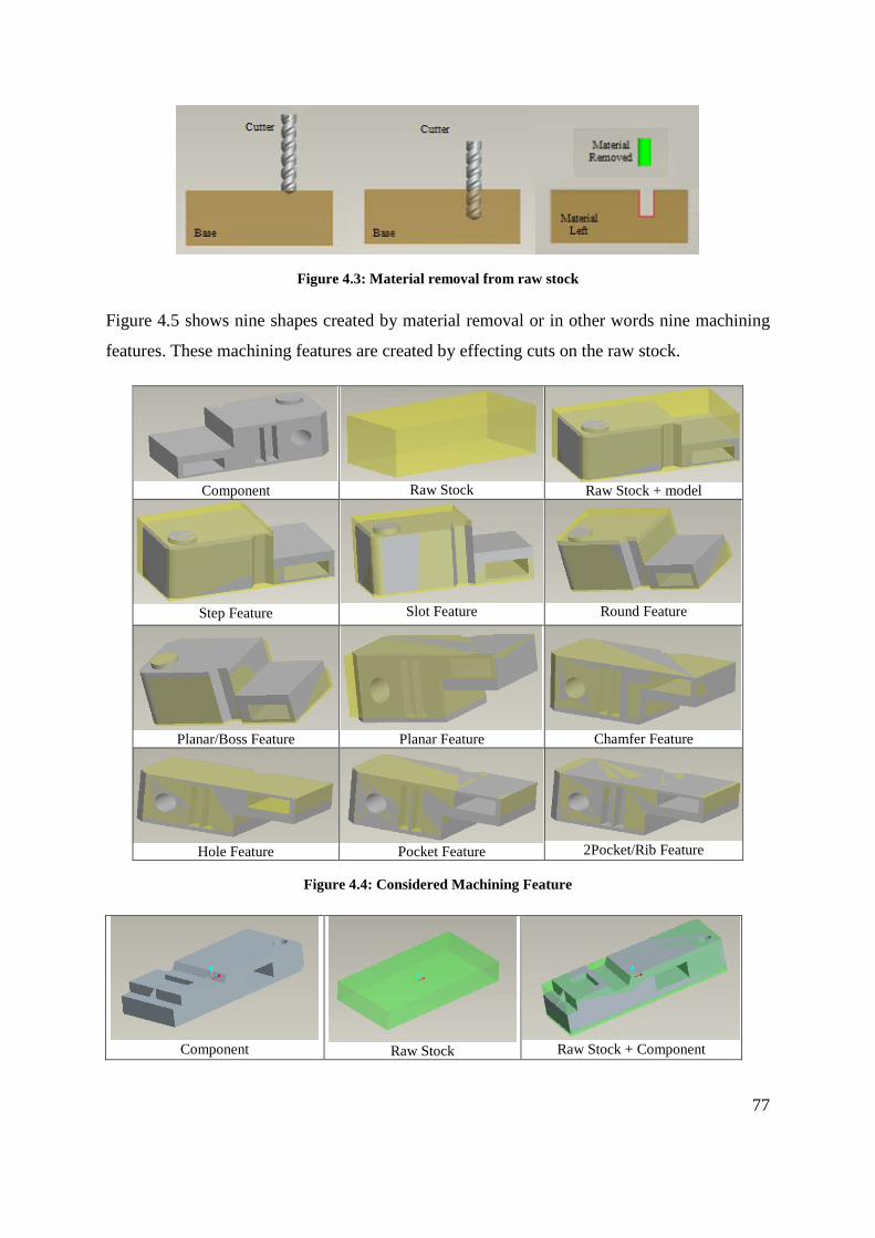
77
Figure 4.3: Material removal from raw stock
Figure 4.5 shows nine shapes created by material removal or in other words nine machining
features. These machining features are created by effecting cuts on the raw stock.
Component
Raw Stock
Raw Stock + model
Step Feature
Slot Feature
Round Feature
Planar/Boss Feature
Planar Feature
Chamfer Feature
Hole Feature
Pocket Feature
2Pocket/Rib Feature
Figure 4.4: Considered Machining Feature
Component
Raw Stock
Raw Stock + Component

78
Face
Chamfer
Slot
Round
Blind Pocket
Hole
Through Pocket
Step
Rib
Channel
O Ring
Slab/Boss
Figure 4.5: Machining Feature as described by Expert Machinist
Expert Machinist is a feature based production milling software bolted on to the Pro/Engineer
software that uses machining features. The machining features as described by expert
machinist are tabulated in Figure 4.6. Citroda and Sivaloganathan [73] have shown that the
machining features defined by Expert Machinist are sufficient to define any machining job.
Most of the machining features, like face, step, pocket, hole, chamfer and round, described in
Figure 4.6 are similar to that of Expert Machinist. Features like Slab and Boss are similar to
that of proposed planar feature with island of material left in the middle. Other features like
Rib and flange feature can be created in combination of proposed feature. O-ring feature is
omitted as the feature depends on the cutter diameter. All the jobs described by Expert
Machinist features can also be described by the features given in Figure 4.5. The parameters
of machining features created by Expert Machinist are however inaccessible. Therefore a
feature set that permits the access of its feature parameters was needed and in this research
the set given in Figure 4.5 are being used. The features can actually be considered as both
design and machining features.

79
4.5.1 Design Features and Machining Features in Pro/Engineer
Design Features in Pro/Engineer are features that are available to the designer to create
instances so that a CAD model can be created as an assemblage of design feature instances.
These include features such as protrusion, cut, hole, chamfer and round.
Figure 4.6: Component 1
Consider the component shown in Figure 4.7, which can be created using design instances as
shown in Figure 4.8. The cross section of the object is drawn and a translational sweep was
made to create the object as a protrusion and the design feature used is called a protrusion.
Parameters of the created protrusion feature such as the surfaces and their normal’s can be
obtained using the Application Programmer’s Interface called Pro/Toolkit. The model can be
accessed by Expert Machinist and Machining Features can be created. Figure 4.9 shows the
machining features created by Expert Machinist for the part shown in Figure 4.7. But the
parameters of the created machining features are not accessible.

80
Figure 4.7: Design instance
Setup 1 Setup 2 Setup 3
Figure 4.8: Machining Features (Expert Machinist) and the Object
Another way of creating the model of the component is by removing material called as cut
using CAD software. In this method a block of material called raw stock is subjected to cuts
to form the final component.
Raw Stock
Cut 1
Cut 2

81
Cut 3
Cut 4
Cut 5
Cut 6
Cut 7
Component
Figure 4.9: Making a Component with Cuts
This process of building the model is shown in Figure 4.10 and the design feature created by
Pro/Engineer is given in Figure 4.11. This method however has an advantage because as
shown the model is an assemblage of design feature instances, the cuts, and therefore the
parameters can be accessed through the API, Pro/Toolkit.
Figure 4.10: Feature Tree Showing the Design Feature Instances
The same job can be described using the features defined in Figure 4.6 is shown in Figure
4.12.

82
Figure 4.11: Feature Tree Using the Features Defined in Figure 4.6
(Proposed Machining Features)
In this research work models created are developed with the features described in Figure 4.6
to build the CAD model (as cuts from a raw stock). The parameters are then extracted using
API which is explained in section 4.6.
4.6 Extract Machining Feature Parameters and write them into a file
A model is created as machining instance in CAD, each instance is made of surfaces
consisting of entities like vertex and vectors as shown schematically in Figure 4.13.

83
Figure 4.12: Details of Entities Stored
For simplicity a feature can be treated as a volume bounded by surfaces. A surface is bound
by edges and edges are bound by vertices. The details of edges and vertices are sufficient to
define a surface. However there are other properties that are useful for different applications.
For machining applications the surface normal is very useful. If a cut feature is executed it
will have several constituent surfaces and each surface will have lists of edges, vertices and a
normal vector. However to execute the cut there should be material thus the first feature or
the base feature should be a protrusion.
Figure 4.13: CAD Model of Component 2

84
(a) Feature Tree (b) Model Creation
Figure 4.14: Creation of a Feature Based Model and its Feature Tree
Consider the object shown in Figure 4.14 and the feature tree describing its creation shown in
Figure 4.15(a). It shows that the object is created with a protrusion, chamfer and round
features. The intermediate stages in the creation of the object are shown in Figure 4.15(b).
The base feature was the first feature created and it is a protrusion. It has six surfaces, 12
edges and 8 vertices. The chamfer is the first cut. It has five planar surfaces, 9 edges and 6
vertices. The round is the second cut. It has 6 planar surface, 1 cylindrical surface, 15 edges
and 10 vertices. The objective in this section is extracting these parameters and writing them
into a file. However the vertices, edges and surfaces in the base feature that have been
removed are of less significance in these features and only the new surface, edges and
vertices created are the important ones and these are the ones that have to be extracted and
stored.

85
4.6.1 Parameters of the Chamfer Feature
Consider the chamfer feature highlighted in Figure 4.16 which was created on a block.
Chamfer feature has a created new surface and its entities are 4 vertices, 4 edges and the
vectors.
Chamfer Feature Entities
(a)
Feature id 1 Plane surface
Surface has e1 – Normal Vector
e2, e3 – Direction Vectors 4 vertices v1, v2, v3, v4
forming 4 edges v1-v2, v2-v4, v4-v3, v3-v1 Orientation of Chamfer Feature depends on the
normal vector of the Plane surface.
Figure 4.15: Chamfer Feature
Chamfer feature consist of one surface, having the normal vector and vertex. Using the value
of the normal vector the orientation of the chamfer can be identified. With all the four vertex,
maximum and minimum points of X, Y and Z are identified which in-turn can be used to
identify the range of the axis or the raw stock for the feature can be defined.
4.6.2 Parameters of the Feature Set
Table 4.10 shows the features and the parameters representing them.
Table 4.10: Machining Features and its Entities Planar Feature Entities
Surf id 91 e1 – Normal Vector
e2, e3 – Direction Vectors v1, v2, v3, v4 – Vertex of surface v1v2, v2v3, v3v4, v4v1 – Edges
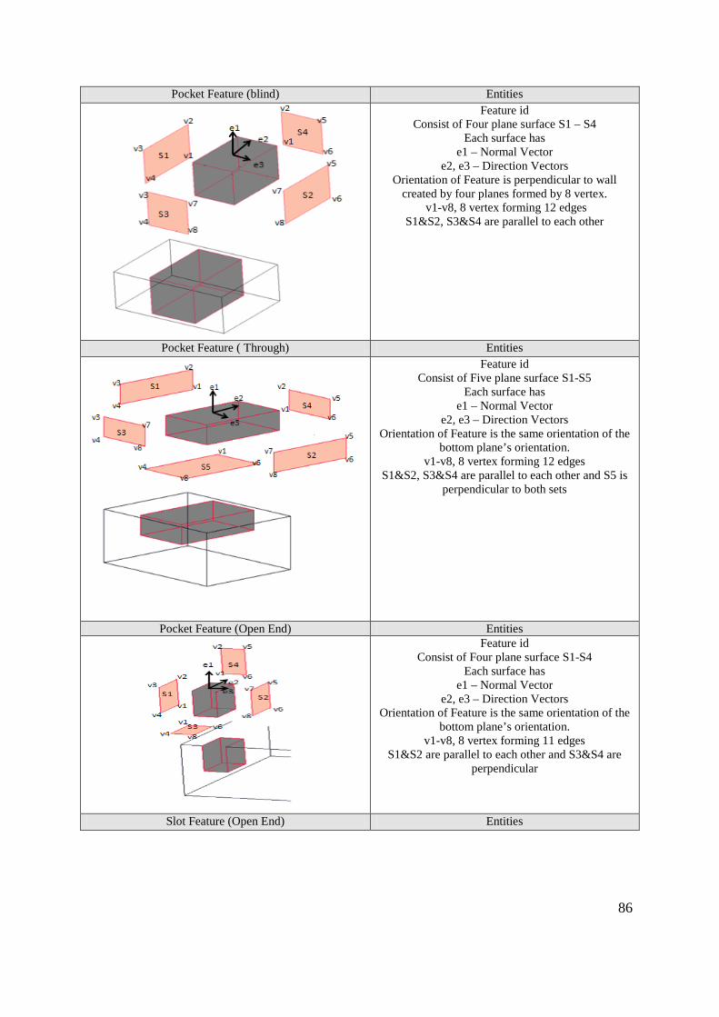
86
Pocket Feature (blind) Entities
Feature id Consist of Four plane surface S1 – S4
Each surface has e1 – Normal Vector
e2, e3 – Direction Vectors Orientation of Feature is perpendicular to wall
created by four planes formed by 8 vertex. v1-v8, 8 vertex forming 12 edges
S1&S2, S3&S4 are parallel to each other
Pocket Feature ( Through) Entities
Feature id Consist of Five plane surface S1-S5
Each surface has e1 – Normal Vector
e2, e3 – Direction Vectors Orientation of Feature is the same orientation of the
bottom plane’s orientation. v1-v8, 8 vertex forming 12 edges
S1&S2, S3&S4 are parallel to each other and S5 is perpendicular to both sets
Pocket Feature (Open End) Entities
Feature id Consist of Four plane surface S1-S4
Each surface has e1 – Normal Vector
e2, e3 – Direction Vectors Orientation of Feature is the same orientation of the
bottom plane’s orientation. v1-v8, 8 vertex forming 11 edges
S1&S2 are parallel to each other and S3&S4 are perpendicular
Slot Feature (Open End) Entities

87
Feature id Three plane surface
Each surface has e1 – Normal Vector
e2, e3 – Direction Vectors Orientation of Feature is the same orientation of the
bottom plane’s orientation. 7 vertex forming 9 edges
Three planes are perpendicular to each other
Slot Feature Entities
Feature id Three plane surface
Each surface has e1 – Normal Vector
e2, e3 – Direction Vectors Orientation of Feature is the same orientation of the
bottom plane’s orientation. 8 vertex forming 8 edges
Two plane are parallel to each other and perpendicular to the bottom plane
Or Two plane are inclined the bottom plane
Channel Feature Entities
Feature id 5 plane surface
Each surface has e1 – Normal Vector
e2, e3 – Direction Vectors Orientation of Feature is the same orientation of the
bottom plane’s orientation. 16 vertex forming 20 edges
Intersection of two slots
Planar/Boss Feature (rectangular) Entities

88
Feature id 5 or 6 plane surface
Each surface has e1 – Normal Vector
e2, e3 – Direction Vectors Orientation of Feature is the same orientation of the
top plane’s orientation. 8 vertex forming 12 edges
Planar/Boss Feature (Cylindrical) Entities
Feature id 2 cylindrical and 1 plane surface
Each surface has e1 – Normal Vector
e2, e3 – Direction Vectors Orientation of Feature is the same orientation of the
top plane’s orientation.
Round Feature (Prismatic) Entities
Feature id 1 cylindrical surface
Surface has e1 – Normal Vector
e2, e3 – Direction Vectors 4 vertex forming 4 edges
Orientation of Feature is the same orientation of that of cylindrical surface.
Hole Feature (Through) Entities
Feature id 2 Cylinder and 1 Plane surface
Each Surface has e1 – Normal Vector
e2, e3 – Direction Vectors Orientation of Feature is the same orientation of that
of bottom Plane surface.
Hole Feature (Blind) Entities

89
Feature id 2 Cylinder and 1 Plane surface
Each Surface has e1 – Normal Vector
e2, e3 – Direction Vectors Orientation of Feature is perpendicular to the
orientation of cylindrical surface.
Rib Feature/Combination of 2Step and 1Chamfer Entities
Feature id 5 Plane surface
Each Surface has e1 – Normal Vector
e2, e3 – Direction Vectors Orientation of Feature depends on the chamfer feature created between the two step features.
Thus the feature set used in the research work are tabulated in Table 4.10 have a definite
dataset associated to each one of them.
4.7 Read and Process Parameters from the file and identify Features for a Single Setting Features are first identified, and then depending on the type of cut and number of surface they
are grouped into Machining Features. Individual surface entities of the machining feature are
collected and analyzed to identify two parameters a) Setup and b) Range of the feature.
Number of Setup for the component can be identified from the number of Machining Feature
and its orientation. Orientation of the machining features depends on bottom surface
orientation, which can be identified from its surface normal. Few machining feature like blind
feature does not consist bottom surface, then their orientation is identified from the existing
surface. If the surface normal of different machining feature have the same value, then the
orientation of the features are in the same direction, if different they require additional setup
for each different group of values. The process of identifying number of setup is shown in
Figure 4.17.

90
Figure 4.16: Process Flow chart to identify number of Setup
Range of the Machining Feature can be calculated from vertex entities of the surfaces which
creates the machining feature as shown in the flow chart in Figure 4.18. Calculating
maximum and minimum limits of all the vertices that created the feature, the range of the
machining feature can be identified. Grouping all the of Machining Feature’s range, the
working area required for the component can be found.

91
Figure 4.17: Process Flow chart to identify Range of X, Y, Z axis
4.8 Further inputs and generation of alphanumeric code
Orientation and limitation of machining features would not be sufficient to select the
right machine tool for machining. Further details are required as input for optimizing the
selection process like (a) Spindle details (Speed and feed rate), (b) Cutting Tool (changers
and carousel), (c) Accuracy, (d) repeatability and (e) Fixture details.
Spindle details are important as they holds the cutting tool, the speed and feed are
vital accept that are required for finish and removal of material. High speed and low feed
produces a high surface finish and low speed and higher feeds are used for the faster material
removal. Depending on the required surface finish and need of the finished material the
spindle details are requested from the user. It is represented as the spindle details of machine
tool feature.
Automation of the process with Cutting tool and pallet changer details are also
considered as input to reduce the setup time and quick change. Certain machining features
can be done quickly with use of more than one cutting tool on the other hand certain
machining features might only use one tool. The number of tools and type of the tool change
is not identified as it would require other parameter like the material selection, mass property
and surface finish of the component but rather considered as an input.

92
Accuracy of positioning to higher standard is achievable with present day machine
tools, but not all machining operation requires a high standard. It is important to consider as
higher accuracy may take longer machining time from a high end machine tool. Accuracy is
also taken as input as this could vary depending on the type of finish and requirement of the
component.
Repeatability in modern machine tool is one of the factors that influence the accuracy.
Repeatability is considered for a high accuracy machining component as low repeatability
might cause a higher tolerance to the finished component. Repeatability is considered as input
for selection of machine tool in this research work.
Fixtures are used to hold the machining component in required position for tool to
position conveniently and to machine faster. The fixture can sometime come into machining
path, so it is important to consider the location of fixture and to identify the probability of
feature blocking any of the machining features. If the fixture creates obstruction for
machining any machining features it become inevitable to move the machining features into
different orientation or to break the orientation into two setups. Different types of fixture are
considered as input for selection of suitable machine tool, identifying special fixture need and
there interference with machining is not considered in this research work.
The various factors extracted from the machining features and the acquired by user
input are used to create alphanumeric code.
4.9 Comparing and marrying the alphanumeric code
There are two sets of alphanumeric codes generated first one from the machining
component features and the second code consisting details of machine tool features. The code
from machining component features consists of two sections a) user input and b) capacity.
The capacity details are extracted from components using API program and the other
required details are requested from user. Machine tool features are created as alphanumeric
code from alphanumeric strings of machine details. This matching of both the alphanumeric
codes is shown in Figure 4.19.

93
Figure 4.18: Intended marriage between alphanumeric code
4.10 Obtain requirement from the user and select the Machine tool
The intended alphanumeric code is not complete without a user interface, where the
details of the machining features can be contributed. The interface should be able to request
the details that are identified in chapter 4.2 for generation of alphanumeric code for the sub-
system. The interface on the other hand should also interact with a temporary database which
stores the details of the machining feature. The details are formatted together to create the
alphanumeric code when requested for machining features.
The second interface for the machine tool’s alphanumeric code should be able to
interact with the database of the machine tools and generate alphanumeric code for them. The
interface should also be able to create, modify, delete and query the machine tool database as
requested by the user.
A third interface would be created that would use the alphanumeric code of the
machining features to query the database of the machine tool. The results of the selected
machine tools would be suitable for that particular machining component and its features.
The selected machine tools would be displayed as list, and further details of individual
machine tools would be displayed.

94
Chapter 5: Implementation
5.0 Introduction
This chapter explains the implementation of methodology outline in the chapter 4 as shown in
Figure 5.1 using Microsoft Office Access as the database, Pro Engineer as the CAD software,
and Pro/TOOLKIT as the Application Program Interface. As outlined in the methodology a
database with all necessary details of machine tools, each with defined alphanumeric strings
to generate the alphanumeric code has been created. In the similar way software has been
developed to query the CAD model which is created as an assemblage of cut features.
Figure 5.1: Process flow chart for selection of machine tool
The results of the query would extract the feature properties using Application program
interface, Pro/TOOLKIT. The data collected from the Pro/TOOLKIT is written into a flat
file database in Microsoft excel. Details from the structured database is read using a second
software program created using Visual Basic (VB) for analysing the data to (a) identify the
number of setups (b)decide the orientation of the machining feature and (c) to determine the
range for machining the features. Further the VB software would request the user to input
other machining details before the alphanumeric code for the given component is created.
The alphanumeric code thus generated is used as the key to search the machine tool database
and this extracts suitable machine tools.

95
5.1 Essential features of a Machine Tool
Machine Tool features identified in chapter 4 are entered into the database as alphanumeric
strings. The identified alphanumeric strings are represented as follows:
• Make and model: This string would consist, details of Manufacture name and model
as one variable. The length of the string is not set as it can be varied for diverse range
of models and manufacture, to accommodate all possible combination and length this
is kept to the maximum possible length in the data field. Figure 5.1 shows few
different machine tool model and manufacture with their representation string.
Presently machine tools are identified using make and model specified by their manufacturer.
This can be incorporated as an alphanumeric string for the alphanumeric code, which in-turn
would help the machinist to select a specific manufacturer’s model for machining.
Table 5 1: Manufacture Name & Model String Manufacture name and Model Number String
HURCO VM1 HURCO-VM1 HARDINGE VMC 480 P3 HARDINGE-VMC-480-P3
HAAS VF-2TR HAAS-VF-2TR
• Number of axis: Total number of traverse and rotary motions performed by the
machine tool is represented in this string. String consists of two digits numeric
variable which can accommodate the variation of motions from 1 to 99. Table 5.2
shows the model and the number of axis representation as string.
Table 5.2: Axis String
Manufacture name and Model Number
Axis String
HURCO VM1 3 03 HARDINGE VMC 480 P3 3 03
HAAS VF-2TR 5 05
Number of setups in a machining operation can be reduced by increasing the freedom of the
machine tool. Presently number of axes in a machine tool is identified by the model type
which can be deceiving, as retrofit or optional additions in the same model can alter number
of axis.

96
• Repeatability: Repeatability in microns is represented as 2 digit numeric variable that
can represent the machine tools capability. Table 5.3 represents the repeatability value
in string.
The ability to re-visit to a same location has implication a) from which direction has the axis
motion have been made and b) if the point is approached by two motions of two different
directions such as work table and cutting tool. A good repeatability is difficult to achieve has
it involves hysteresis of mechanical motions, and feedback. Repeatability is one of the
important factor that is considered for high precision machining. Repeatability of a machine
tool can be found in the details of the machine tool but are not normally displayed with the
machine model and make.
Table 5.3: Repeatability String
Manufacture name and Model Number
Repeatability String
HURCO VM1 0.0025mm 25 HARDINGE VMC 480 P3 0.002mm 20
HAAS VF-2TR 0.0025mm 25 • Accuracy: Accuracy in microns is represented as 2 digit numeric variable that can
represent the machine tools capability. Table 5.4 represents accuracy value as strings.
Table 5.4: Accuracy String
Manufacture name and Model Number
Accuracy String
HURCO VM1 0.005mm 50 HARDINGE VMC 480 P3 0.005mm 50
HAAS VF-2TR 0.002mm 20
Accuracy is necessary for positioning the cutting tool and job at the right position for
accurate machining as this defines the machines ability to position the axes which it has not
visited before. Accuracy of machine tool can be found from the details supplied by the
manufactures but cannot be identified from the model or make.
• Automation: Consist of two set of string a) tool changing system and b) pallet
changing system. First set represent the pallet and the second represents the tool
systems. Each set of string is normally made up of five characters, the first saying
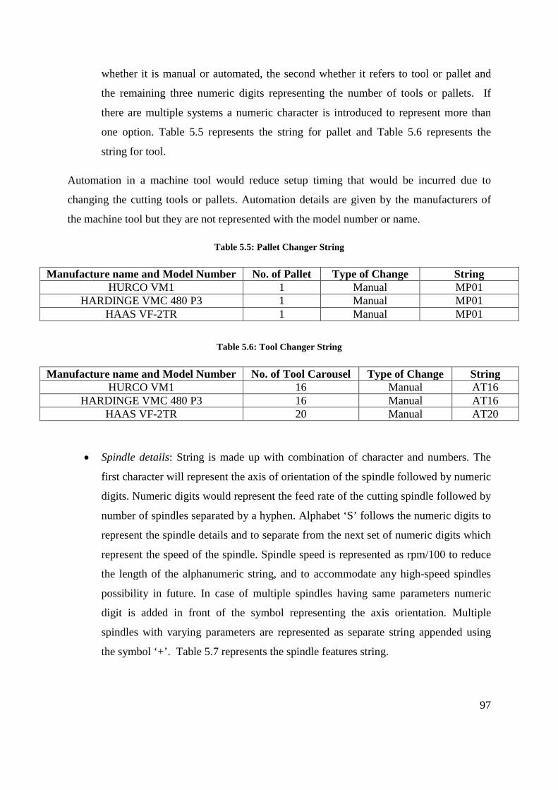
97
whether it is manual or automated, the second whether it refers to tool or pallet and
the remaining three numeric digits representing the number of tools or pallets. If
there are multiple systems a numeric character is introduced to represent more than
one option. Table 5.5 represents the string for pallet and Table 5.6 represents the
string for tool.
Automation in a machine tool would reduce setup timing that would be incurred due to
changing the cutting tools or pallets. Automation details are given by the manufacturers of
the machine tool but they are not represented with the model number or name.
Table 5.5: Pallet Changer String
Manufacture name and Model Number No. of Pallet Type of Change String HURCO VM1 1 Manual MP01
HARDINGE VMC 480 P3 1 Manual MP01 HAAS VF-2TR 1 Manual MP01
Table 5.6: Tool Changer String
Manufacture name and Model Number No. of Tool Carousel Type of Change String HURCO VM1 16 Manual AT16
HARDINGE VMC 480 P3 16 Manual AT16 HAAS VF-2TR 20 Manual AT20
• Spindle details: String is made up with combination of character and numbers. The
first character will represent the axis of orientation of the spindle followed by numeric
digits. Numeric digits would represent the feed rate of the cutting spindle followed by
number of spindles separated by a hyphen. Alphabet ‘S’ follows the numeric digits to
represent the spindle details and to separate from the next set of numeric digits which
represent the speed of the spindle. Spindle speed is represented as rpm/100 to reduce
the length of the alphanumeric string, and to accommodate any high-speed spindles
possibility in future. In case of multiple spindles having same parameters numeric
digit is added in front of the symbol representing the axis orientation. Multiple
spindles with varying parameters are represented as separate string appended using
the symbol ‘+’. Table 5.7 represents the spindle features string.

98
Spindle is a crucial component in a machine tool as this holds the cutting tool for machining.
The feed and speed of the spindle is useful for deciding the raw stock material on which the
component can be machined. The information about the spindle are represented briefly in the
details given by the manufactures but multiple spindles or their direction are not normally
represented in the name or model description.
Table 5.7: Spindle String
Manufacture name and Model
Number
Axis or Orientation
Max Feed Rate for Cutting
No. of Spindle
Spindle Speed in rpm/100
String
HURCO VM1
Z 19m/min 1 80 Z19-1S80
HARDINGE VMC 480 P3
Z 12m/min 1 100 Z12-1S100
HAAS VF-2TR
Z 16.5m/min 1 75 Z16.5-S75
• Fixture: Fixture details or the type of fixture present in a machine tool is abbreviated
to four character string.
Fixture details are important feature that is necessary to secure and hold the component for
machining. Fixture can be created for a particular component or standard fixture like T-Slots,
clamps can be used.
• Controller: Controller model is abbreviated to four character string for representation.
Table 5.8 represents the controller strings of few different controllers.
A controller supplants a machine tool operator and regulates the motions, spindles, feed and
subsystems of machine tool in tandem. Depending on the number of subsystem to be
regulated simple to complex the control systems are used. Controller model are not
represented on the machine tool model or the name as these are optional but for a machining
a better control system can provide a higher level of finish on a component.
Table 5.8: Controller String
Manufacture name and Model
Number
Controller String
HURCO Hurco HURC

99
VM1 HARDINGE VMC 480 P3
Fanuc FANU
HAAS VF-2TR
Haas HAAS
• Motion blocks: Each of the motion performed by the machine tool can be considered
as separate blocks. Each block is represented as a string with combination of one
character followed by numeric digits. The first character will represent the type of
motion provided by the block and the following digits represent the motion value. For
a traverse motion value would be distance in mm and for rotation in angle. The
numeric digits are not restricted as to accommodate larger axis of motions. Table
5.9represents the all the motion of the machine tool as string.
Table 5.9: Motion Block String
Manufacture name and
Model Number
X Axis Travers in mm
Y Axis Traverse
in mm
Z Axis Traverse
in mm
a rotation
angle
b rotation
angle
String
HURCO VM1
660 356 457 - - X660:Y356:Z457
HARDINGE VMC 480 P3
480 400 430 - - X480:Y400:Z430
HAAS VF-2TR
760 508 508 120 369 X760:Y508:Z508:a120:b:360
Some of the machine tool represents the axis traverse of the machine tool in their model name
which may be X, Y or Z. It is important to define the machining space depending on the X, Y
& Z traverse distance. Inclusion of motion traverse distance in the code and the rotational
angle would be useful to identify the machining space.
• Other Systems: Coolant, swarf & dust removal systems are represented using three
characters respectively. Presence or absence of the three systems is flagged by ‘P’ or
‘F’. Any further inclusion of any other system can be include as the forth and
subsequent character along side of the existing string. Table 5.10 represents the
various subsystems present in a machine tool and its representation string.
By product of machining would create chip and heat between tool and raw stock. Coolant is
necessary for absorbing the heat dissipated and swarf and dust removal system of chips.

100
Subsystems are not represented with the make and model name of the machine tool
manufactures presence or absence of these systems would help to remove the by-products of
machining.
Table 5.10: Subsystem String
Manufacture name and Model
Number
Coolant System
Swarf Removal system
Dust Removal System
String
HURCO VM1
Present Absent Absent PFF
HARDINGE VMC 480 P3
Present Absent Absent PFF
HAAS VF-2TR
Present Absent Absent PFF
5.2 Establishment of Alphanumeric Code
The alphanumeric strings created are systematically assembled in sequence, starting from the
first string consist of ‘Make and model’ to ‘Subsystem’ as shown in Table 5.11 which would
create the alphanumeric code of the machine tool. Each string is separated using colon when
represented in the alphanumeric code. Motions string are represented in the code starting
from component string to the cutting tool string which form a loop. Some machine tools
might have more than one spindle which would create multiple loops which can be
represented using ‘+’ symbol were the loop separates. The static block or the stationary block
along the loop of the motion is represented as ‘O’ which is included onto the motions string
which the stationary block carries. Representation of motion string and the location of the
stationary block are crucial as this can be used to identify the type of milling machine
structure as described in Table 5.12.
Table 5.11: String Sequence
Manufacture and model
No. of Axis
Repeatability Accuracy APC ATC Spindle details
Fixture Controller Motions Sub system
Table 5.12: Location of Stationary Block
Location of Stationary block
Type of milling Machine
At the start of motion string
Gantry or Column

101
After X,Y motion string combination
Knee milling
Alphanumeric code not only highlights the capacity and features but can also identify type of
machine tool by the orientation of the spindle.
5.3 Creating database and generating alphanumeric code for Machine Tool Feature
Figure 5.2: Visual Basic program for database
The various features required for generating the alphanumeric code for machine tool are
collected to create a database of machine tool. Interface program created using Visual Basic
would request the user to enter the details of machine tool. Figure 5.1 shows the interface
program created using Visual Basic. Using the features, the software would create the string
to generate alphanumeric code. The interface software consists of three parts each separated
by a vertical line.
First part of the interface software would request user to enter details like a) make & model
and b) motion details. Motion details in the first part are entered starting from the component
to the cutting tool as instance of block which performs the motion. The block of information
would consist of a) axis convention, b) the motion value, and c) if they branch out.

102
a) Axis convention: The nomenclature of the axis would follow the same convention as
used by right hand coordinate system and in case of non motion block it is represented
as ‘O’.
b) Motion value: Maximum traverse motion value is entered in mm and for rotational
maximum possible rotation angle is entered.
c) Branch out: Following the block of motion from component to machine tool, some
machine tool would consist two spindle heads as shown in Figure 4.3. Representation
of block from component to cutting tool would branch after the base motion. After the
motion of the base the loop separates. Each separated loop from the base to the cutting
tool is shown with a ‘+’ as join to the base motion.
The number of motions block including the stationary block is restricted to 11 in the created
software interface, which can be further increased if required.
Second part would request for the user to enter details of a) spindle, b) automation, c)
accuracy, d) repeatability e) Fixture, f) Controllers and g) other system present in the machine
tool. Values are entered by the user on the interface form of the software are first validated
for the type and character format. On validation of all the feature specific alphanumeric string
are created at the back end of the software to generate the alphanumeric string. The entered
feature values and generated alphanumeric code of the machine tool are updated on to
database by the interface program.
The third part of the interface would request for any picture of the machine tool that can be
load as with the location path. The created software would not only allow the user to add new
records of machine tool to the database but also view, modify or delete any of the existing
records from the database.

103
Table 5.13: Alphanumeric Code
Duguard-VMC660:
03: 30: 40: MP01: AT24: Z30-1S80: STAN: HEID: X660: Y550: 0Z510: PFF
Man
ufac
ture
and
m
odel
No.
of A
xis
Rep
eata
bilit
y
Acc
urac
y
Palle
t cha
nger
Cut
ting
tool
Spin
dle
deta
ils
Fixt
ure
Con
trolle
r
X tr
aver
se
Y tr
aver
se
Col
umn
and
Z tra
vers
e
Sub
syst
em
Coo
lant
, Sw
arf,
Dus
t
Consider the Machine tool features of Duguard VMC660 in the appendix ##, its features
details are tabulated in table 4.4 and the representation of Machine tool as alphanumeric code
is represented in Table 5.13.
5.4 Some Machine Tools and their Alphanumeric Codes
The table 5.14 represents alphanumeric codes of commercially available machine tools.
Table 5.14: Example of Machine tool and its Alphanumeric Code
Machine tool Alphanumeric Code
4 Axis Vertical Machining Centre
DIXI-DHP50:04:90:09:AP02:AT100:Z24-
1S120:STAN:HEID:a360:X700:Y700:0Z700:PPP

104
6 Axis Vertical Machining Centre
BOKO-WF3/12:06:20:10:MP01:AT40:W10-
1S31.5:STAND:FANU:c360:X1800:Y1200:0Z860:b90:w
300:PPF
Twin Spindle 3 Axis
EMAG-S0322:04:20:20:MP01:AT24:Z20-
2S50:STAN:FANU:X600:Y500:0Z600:PPF
Twin Spindle 5 axis
EMAG-BAS03:06:20:20:MP01:AT24:Z20-
2S50:STAN:FANU:c360:a90X60:Y500:0Z600:PPF

105
Horizontal Machining Centre
HAAS-EC440PP:04:30:50:AP05:AT70:Z26-
1S120:STAN:HAAS:b360:X508:Y508:0Z508:PPF
5.5 Preparing the CAD model suitable for machining features identification
Figure 5.3: Component
Consider the component shown in Figure 5.3, which has to be modelled in Pro Engineer.
There can be various combination of modelling instance that can be used to create the model.
As the machining process removes material from the raw stock it is crucial to create the
model as instance of material removal only and not addition when modelling in Pro Engineer.
Figure 5.4 shows the creation of the component shown in Figure 5.3 as instance of material
removal. These design instances in Pro Engineer which removes material can be a CUT,
CHAMFER, HOLE or ROUND.

106
Raw Stock
Slot
Round 1, 2, 3, 4
Hole 1
Hole 2
Hole 3
Hole 4
Slot
Step
Chamfer
Figure 5.4: Preparation of model using material removal
Design instance in Pro Engineer is accessed by the created Application Program Interface
software using Visual C ++, that uses functions provided by Pro/TOOLKIT. Considering the
design instance of Chamfer which removes material and creates a single plane surface, and
Round would create a single cylindrical surface where as the Cut can produce both
cylindrical and plane surfaces depending on the sketch created for the cut, similarly hole
instance can produce both surface depending whether it’s a simple, complex, through or
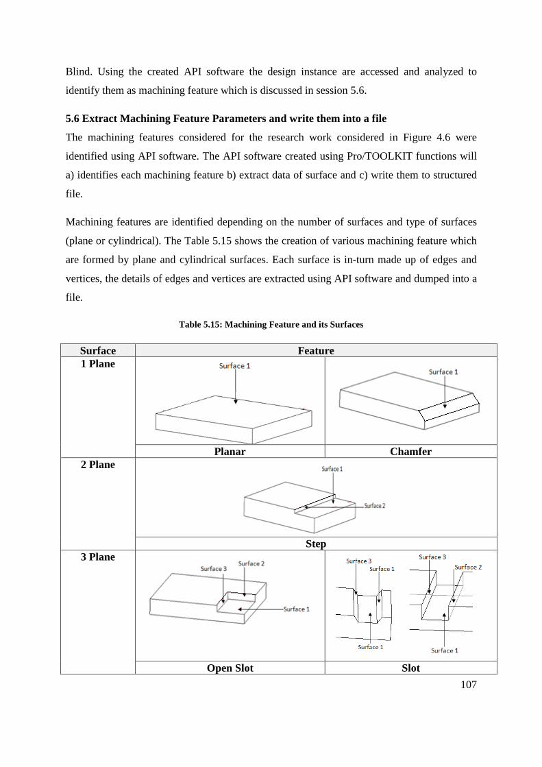
107
Blind. Using the created API software the design instance are accessed and analyzed to
identify them as machining feature which is discussed in session 5.6.
5.6 Extract Machining Feature Parameters and write them into a file
The machining features considered for the research work considered in Figure 4.6 were
identified using API software. The API software created using Pro/TOOLKIT functions will
a) identifies each machining feature b) extract data of surface and c) write them to structured
file.
Machining features are identified depending on the number of surfaces and type of surfaces
(plane or cylindrical). The Table 5.15 shows the creation of various machining feature which
are formed by plane and cylindrical surfaces. Each surface is in-turn made up of edges and
vertices, the details of edges and vertices are extracted using API software and dumped into a
file.
Table 5.15: Machining Feature and its Surfaces
Surface Feature 1 Plane
Planar Chamfer 2 Plane
Step
3 Plane
Open Slot Slot

108
4 Plane
Through Pocket Open Pocket
5 Plane
1 Cylindrical
Round
2 Cylindrical
Blind Hole
2 Cylindrical +
1 Plane
Through Hole Boss

109
5.6.1 Creation of Menu
On execution of the created API software, it would create a menu along side of the existing
Pro Engineer’s tool bar menu, the created menu ‘Machining Features’ and submenu is shown
in Figure 5.5.
Figure 5.5: Created Menu in Pro Engineer
API software is created using Visual C ++ complier in Dynamic Linked Library mode. The
software is created in DLL mode so that required library functions are first complied and
stored in a library with extension .DLL. Using the synchronous application of Pro Engineer
the .DLL file is loaded using an intermediate file called registry. The registry file is read
through the auxiliary application from Pro Engineer to execute the API software created. The
loading of the registry file through the auxiliary application is shown in Figure 5.6.

110
Figure 5.6: Starting Auxiliary Application in Pro Engineer
5.6.2 Selection of Submenu
On selection to identify any particular machining feature from the sub menu, the API
software would then highlight the edges of the surfaces that form the machining feature.
Further the user would be prompted to select the surfaces which create them. After selection
of surface, any further occurrence of the same machining feature would be highlighted again
and the user prompted unless the there is no further instance of the same machining feature.
Consider the component shown in Figure 5.7(a) consisting of single slot feature. On selection
to identify slot feature from the sub menu, the API software identifies the slot feature and
highlights the edges as shown in Figure 5.7(b).

111
(a)
(b)
Figure 5.7: Component with Slot Feature
After the highlighting the machining feature by the software it would be prompted with a
message box to the user to select the surfaces whose edges are highlighted. The process of
selecting surface is done manually to avoid any confliction which might arise due to
intersecting of surface. The process of surfaces selection for a slot feature is shown in Figure
5.8. The process of selection is done from the bottom surface or the surface that orientates the
feature followed by side surface which forms the wall this is followed for all the machining
features. This process of selection is followed to create uniformity in dumping the data of the
surfaces.
Highlighted Feature
Selection of Bottom Surface
Selection of Second
Surface
Selection of Third
Surface
Figure 5.8: Process of Surface selection from Machining Feature
On selection, if the option is not a surface then the option is discarded and if it is the surface
then data of the surface is extracted by the API program. The data for the three surface of the
slot in Figure 5.7(a) are shown in Table 5.16, Table 5.17, and Table 5.18.

112
Table 5.16: Bottom Surface
Bottom Surface Parameter Value
Geometry item SURFACE Id 620
Surface extremes (min) X, Y, Z
-125.00, -80.00, 35.72
Surface extremes (max) X, Y, Z
125.00, -120.00, 35.72
Orient -1 Type Plane
Vector Along U e1 ( 0.00000, -1.00000, 0.00000) Along V e2 ( -1.00000, 0.00000, 0.00000)
Surface Normal e3 ( 0.00000, 0.00000, -1.00000)
Table 5.17: Second Surface
Second Surface Parameter Value
Geometry item SURFACE Id 622
Surface extremes (min) X, Y, Z
-125.00, -120.00, 35.72
Surface extremes (max) X, Y, Z
125.00, -130.00, 50.00
Orient -1 Type Plane
Vector Along U e1 ( 0.00000, -0.57358, 0.81915) Along V e2 ( -1.00000, 0.00000, 0.00000)
Surface Normal e3 ( 0.00000, -0.81915, -0.57358)
Table 5.18: Third Surface
Third Surface Parameter Value
Geometry item SURFACE Id 618
Surface extremes (min) X, Y, Z
-125.00, -80.00, 35.72
Surface extremes (max) X, Y, Z
125.00, -70.00, 50.00
Orient -1 Type Plane
Vector Along U e1 ( 0.00000, -0.57358, -0.81915) Along V e2 ( -1.00000, 0.00000, 0.00000)
Surface Normal e3 ( 0.00000, 0.81915, -0.57358)

113
The extracted details of each surface are written into the database by the software in a
structured way so that the data can be read or queried. The Figure 5.9 shows the structured
format of the required surface data details which are ready for any query. The data consist of
surface normal vector, its orient direction along the axis, surface id and maximum and
minimum limit of the surface.
Figure 5.9: Entity Details of the Surface in database
5.6.3 Invoked Pro/TOOLKIT functions on selection of Submenu
On selection of submenu to identify a machining feature, a continues chain of functions are
called in response to a) identify the design feature as machining features, b) highlight the
identified machining feature and c) prompt user to select surfaces of the machining feature.
Consider the model in Figure 5.10(a) and its design feature Figure 5.10(b). The component
consists of single Slot Feature when user select the option to identify the slot feature from the
menu, the command triggers a chain of functions in sequence. The first function called in the
sequence for the selected option would be a user created function called “MenuSlotFunc( )”.
Each menu option has a unique function created in the API application to be triggered.
(a)
(b) (c)
Figure 5.10: Component with Slot Feature
“MenuSlotFunc( )” in turn will invoke the next function called “SlotFunc( )”, which is stored
in the file called “slot.c”. The “SlotFunc( )” and “slot.c” is a part of created API application
software. “SlotFunc( )” will then call the Pro/TOOLKIT functions “ProMdlCurrentGet( )” to
identify the model in the current section of Pro Engineer. Output of the “ProMdlCurrentGet(
)” would be a model identification number (mdl_id) which would be used to for the next
function called “UserFeatureVisit( )”. The model identification number (mdl_id) is passed on

114
to a function called “UserFeatureVisit( )” which collects the data’s consisting of the design
features as arrays or data structures used for creation of model. Data structures for the model
shown in Figure 5.10(a) would consist of i) Protrusion id47 and ii) Cut id83 as shown in
Figure 5.10(b) which makes up the model. The collected data structures are passed on to the
next function called “UserRibFind1( )” created as part of API software would identifies only
the design instance cut. The cut instance is passed to the next function of Pro/TOOLKIT
called “ProUtilCollectFeatureGeomItem( )”, which collects various geometric features which
create the design instance. From the collected geometric features, surfaces are identified
which can be a plane or cylindrical surface. The identified surfaces of the design instance cut
are checked to ensure the instance is only made up of three surfaces. If the instance is not
made of three surfaces then the instance is not a slot feature and is omitted. The cut instance
id83 for the Figure 5.10(a) consist of three plane surface as shown in Figure 5.10(c) which
confirms to form the slot feature.
Table 5.19: Pro/TOOLKIT Functions for Highlight
Function Pro/TOOLKIT or
Create API software Functions
Input of Fn Output of Fn
MenuSlotFunc( ) Created API fn - Call SlotFunc( ) SlotFunc( ) Created API fn - Call ProMdlCurrentGet( )
ProMdlCurrentGet( ) Pro/TOOLKIT fn - Mdl_id UserFeatureVisit( ) Pro/TOOLKIT fn Mdl_id Design Instance as (array)
UserRibFind1( ) Created API fn Array of design
instance
Cut instance
ProUtilCollectFeatureGeomItem( ) Pro/TOOLKIT fn Cut instance Surfaces of Cut instance ProSelectionHighlight( ) Pro/TOOLKIT fn Surface of Cut
instance Highlight the edges of cut instance surfaces and call
UserVist1( ) fn
Once the feature confirms the requirement as machining feature of slot, edges of the surface
which forms the features is highlighted using the function “ProSelectionHighlight( )” by
passing the surface details of the instance. The Table 5.19 represents all the function’s input
and output that are used to highlight the edges of surface which create a slot feature.
Parameter of each feature is identified through surfaces which form them. The process of
selection of surface is done manually to avoid any confliction which might arise due to

115
intersecting of surface. The process of selection is done from the bottom surface or the
surface that orientates the feature followed by side surface which forms the wall. Once the
surface edges are highlighted, function “UsrVist1( )” is called. The “UsrVist1( )” is created as
part of API software, the function calls “ProMdlCurrentGet( )” to get the current model in the
session. The model details is passed on to the next function called “ProTestGeomShape( )”
and the function “ProSelect( )” is also called to request the user to input a selection. The input
selection is cross checked with the current model in session. The selection is passed on to a
function ProUtilGeomItemDump( ) which identifies the selection, if the selected option is
surface then ProSurfaceInit( ) confirms the surface as part of the model and then
ProSurfaceToGeomitem( ) identifies the geometric details that forms the surface like the
vertex and edges. Using the geometry details of the surface a) surface extremes are calculates
using the function ProSurfaceExtremes( ) and stored in array, b) the surface details is passed
on to ProSurfaceGeoItemShapeDump( ) and then to ProUtilSurfacedataPrint( ) which consist
of ProPlanedataGet( ) and ProCyclinderdataGet( ) which collects vector and its data are
collected. Table 5.20 represents all the function that are used to collect the data of the
selected surface which were highlighted.
The data collected by the function are written on to a dump file using the software itself. The
dumped data is a flat file database that is saved as a structured data format in excel. The
database is saved as structured format so that the data can be accessed for reading and
querying.

116
Table 5.20: Pro/TOOLKIT function for Data
Function Pro/TOOLKIT or
Create API software
Functions
Input of Fn Output of Fn
UserVist1 ( ) Created API fn - Call ProMdlCurrentGet( ) ProMdlCurrentGet( ) Pro/TOOLKIT fn - Model type and Call
ProUtilGeomItemDump( ) ProUtilGeomItemDump( ) Pro/TOOLKIT fn ProMdl Call ProSelect( )
ProSelect( ) Pro/TOOLKIT fn - Selection ProSurfaceInit ( ) Pro/TOOLKIT fn Selection,
ProMdl, Checked both are same
ProSurfaceToGeomitem ( ) Pro/TOOLKIT fn Surface, ProMdl Geometry of surface, ProSurfaceExtremesEval( ) Pro/TOOLKIT fn Surface Extremes of surfaces are calculated ProUtilSurfacedataPrint ( ) Pro/TOOLKIT fn Surface Data of surface – Type, orient is
collected ProPlanedataGet ( ) Pro/TOOLKIT fn Surface Dep. on surface type vector is
found ProCyclinderdataGet( ) Pro/TOOLKIT fn Surface Dep. on surface type vector is
found
5.7 Identifying Number of Setup and Range
Figure 5.11: Process Flow of VB program

117
A software using visual basic (VB) program was created that would a) read and query the
data populated in the database by the API software, b) analyses the number of setup and c)
identify the range of the machining. VB Program would query the database twice, first
instance to identify the number of setup and second for the range of the machining. The
process flow diagram in Figure 5.11 shows the working of VB software.
The first query would request for surface normal vector details of all the surfaces which
orients the machining feature that would consist details from the bottom surface or the
surface which is selected first during selection of surfaces. Using normal vector, orientation
of the surface is identified using VB software. The identified orientation is stored in two
clusters a) along positive and negative traverse axis of X, Y, Z and b) along rotation axis a, b,
c. Created VB software would further store the machining feature id and count the number of
setup needed for the machining. Figure 5.12 shows the part of the VB program that shows the
number of setup and it orientation along the axis.
Figure 5.12: Identified Machining Setups using VB Program
Figure 5.13: Identified Range for Machining using VB Program
Second query scan across all the records of the entire surfaces in the database and identify the
maximum and minimum values along X, Y and Z axis. Range of individual axis is calculated
which would be used to identify the maximum and minimum limits in which identified

118
machining feature can be machined. Figure 5.13 shows the part of VB program that
represents the limits of machining.
5.8 User Input for Machining Feature Sub-System
Machining feature’s orientation and range was identified in the previous section 5.7, which
are not sufficient for machining. Further details are necessary like a) cutting tools, b)
accuracy, b) repeatability, d) spindle detail’s, e) feed rate f) any addition axis and e) coolant
& removal system. The need for these features in any machining process is discussed in detail
in section 4.2. In addition details like control type and fixture requirements are also
considered. Controllers are necessary to eliminate the user interface so that various
machining parameter can be control and interconnect to work concurrently. Controllers at
present in machine tools are available in diverse forms from the manufacture or by the
complexity to handle number of axis as discussed in section 2.6.
Figure 5.14: VB form to collect sub-system feature of machining feature
Fixture plays a vital part in the machining as these are important to hold the machining
component rigidly and align them to the cutting tool. Some of the common fixtures are
standard accessories available in machine tools, need for any special feature is also

119
considered if required for machining. These sub-system details were not automated, as there
can be numerous combinations possible. Instead the details are requested from the user in the
VB form as input shown in Figure 5.14.
The form is a simple user interface system were the details like a) spindle speed, b) number
of spindle head, c) feed rate, d) number of tool carousel, e) repeatability and f) accuracy are
entered. Type of tool change, controller and fixture and pre-defined in combo box option
were user selection is request. Additional rotational axis option is included to reduce the
machining setup as check box and rotational angle is request in the text box. It also makes
sure that user cannot select more than two axes of rotation as three axes rotation is not
possible neither available. These sub-feature details are incorporated with the capacity details
in the same form created using VB programming. All the various factors identified and
requested from the user form the alphanumeric string for the machining component. The
representation of these alphanumeric string forms the alphanumeric code of the machining
component.
5.9 Generation of Alphanumeric code for Machining Component
Figure 5.15: Identified Alphanumeric Strings for the component in Figure 5.3
Alphanumeric code of Machining Component is created, using the alphanumeric string
identified in section 4.8. Consider the model in Figure 5.3 the alphanumeric string identified
using the API program as shown in Figure 5.15 would gives us the number of setup,

120
machining range. Figure 5.16 shows the requested inputs for machining the component form
the user to create the alphanumeric string.
Figure 5.16: User input for Machining the Component in Figure 5.3
Alphanumeric string from the program and the user inputs are used to create the
alphanumeric code for the component in Figure 5.3 is shown in Table 5.21.
Table 5.21: Alphanumeric Code of the component in Figure 5.3
03: 01: 03: MP01: AT20: 30-1S90: STAN: FANU: X300: Y200: Z100: B300: PFF
No.
of A
xis
Rep
eata
bilit
y
Acc
urac
y
Palle
t cha
nger
Cut
ting
tool
Spin
dle
deta
ils
Fixt
ure
Con
trolle
r
X tr
aver
se
Y tr
aver
se
Col
umn
and
Z tra
vers
e
b ax
is ro
tatio
n
Sub
syst
em
Coo
lant
, Sw
arf,
Dus
t

121
5.10 Marrying of Alphanumeric Codes of Machine Tool Feature and Machining
Component Feature.
Alphanumeric code generate for the machining component set down the basis for selecting a
machine tool. The alphanumeric code defines the parameters set for machining the
component; these parameter values are extracted from the Component’s Alphanumeric code
and used for selection of machine tool.

122
Chapter 6: Case Study
6.0 Introduction
The component in Figure 6.1 selected for the case study is exhibit model from MACH-2008
for a mill-turn machine tool. Preparation of model is done using Pro Engineer by material
removal instance only. Suitable raw stock is first cut from a block of material, and then cuts
are created to produce the component in CAD. The prepared model is analyzed using the
developed API software to extract the component details. The extracted details are further
stored and read from a database using the created VB software. The software also identifies
the setups and capacity further generates the alphanumeric code for the component. The
generated alphanumeric code of the component is segregated and matched to the machine
tool features from the created database of machine tools. The matched machine tools are
listed in the software for selection by the user for machining. The optimal choice of machine
tool for the component is further discussed.
Figure 6.1: Case Study Component
6.1 Preparation of the Model
A rectangular block of material which fits the component shown in Figure 6.1 is first created
as shown in Figure 6.2(a) and further the block is trimmed using three cut as shown in Figure

123
6.2(b). The Table 6.1 shows the various cuts that were used to model the component in Pro
Engineer including the feature tree.
(a) Raw Stock
(b) Trimmed Raw Stock
Figure 6.2: Raw Stock for the component and trimming
Table 6.1: Creation of the model using cut instance
Feature Tree Cut Instance
Round id 2791
Round id 2833
Round id 2875 Round id 2917
Round id 2959
Round id 3001
Round id 3043
Round id 3085

124
Round id 3127 Round id 3169 Round id 3211 Round id 3235
Round id 3295
Round id 3348
Round id 3401
Round id 3454
Chamfer id 3711
Cut id 3785
Cut id 3831
Cut id 3877
Cut id 3908
Cut id 3951
Cut id 4049
Cut id 4106
Chamfer id 4135
Cut id 4194
Cut id 4270
Mirror ids 4346 &
4402
Pattern (Hole1 [1])
Pattern (Hole2 [1]) Pattern (Hole2
[1])
Round id 5028

125
Round id 5089
Round 5150
Round 5211
Round 5272
Pattern (Hole 4 [1])
Hole id 5447
Hole id 5422
Hole id 5497
6.2 Extraction from the Component
Figure 6.3: Sub menu created by API software
Using the developed API software, a menu option is created along side of the main menu in
Pro Engineer. The option provides a list of sub menu as shown in Figure 6.3, for the user to
select an option to identify various machining feature.
On Selection of a particular machining feature, the software identifies and highlights
machining feature’s edges from the model and further prompts the user to select the surfaces
highlighted by the edges. On selection of the menu “Idy Chamfer Features” the chamfer
features in the model are highlighted one after the other as shown in Table 6.2.

126
Table 6.2: Idy Chamfer Menu
Sub menu Identified Chamfer Features from the model Idy Chamfer
Features
On selection of menu “Idy Round Feature” the following round feature in the model are
highlighted as in Table 6.3.
Table 6.3: Idy Round Menu
Sub menu
Identified Round Features from the model
Idy Round
Features

127
On selection of menu “Idy Step Feature” the following step feature in the model are
highlighted as in Table 6.4.

128
Table 6.4: Idy Step Menu
Sub menu
Identified Step Features from the model
Idy Step Features
On selection of menu “Idy Hole Feature” the following hole feature in the model are
highlighted as in Table 6.5.

129
Table 6.5: Idy Hole Menu
Sub menu Identified Round Features from the model Idy Hole Features

130
On selection of menu “Idy Pocket Feature” the following pocket feature in the model are
highlighted as in Table 6.6.
Table 6.6: Idy Pocket Menu
Sub menu Identified Pocket Features from the model Idy Pocket Features
The surface details of each surface with their normal vector are grouped with respect to
machining feature and tabulated in Table 6.7.
Table 6.7: Data for all the identified machining features
Machining Features Direction Cosine Orient Xmin Xmax Ymin Ymax Zmin Zmax id Chamfer 0 0 -1 1 0.5 28.47 60 28.47 -22.78 20 3721
0 0 -1 1 -60 -0.5 0.5 40.05 -22.78 20 3712 0 0 -1 1 -22.06 -40.05 -55.96 -0.5 -22.78 20 3737 0 0 -1 1 0.5 40.05 -60 -0.5 -22.78 20 3729
Chamfer -0.47315 0.47315 0.74314 1 -69.99 -1.42 1.42 69.99 -62 -62 4136 Chamfer 0 0 1 1 0.5 39.04 49 39.04 -100 -77.61 5273
0 0 1 1 0.5 55 -49 -0.5 -100 -77.61 5298 0 0 1 1 -34.79 -55 -34.8 -0.5 -100 -77.61 5290 0 0 1 1 -49 -0.5 0.5 55 -100 -77.61 5282
Round 0 0 1 1 -20 -0.05 0.05 20 100 120 2792 Round 0 0 1 1 -14.16 -20 -14.16 -0.05 100 120 2834 Round 0 0 1 1 0.05 20 -20 -0.05 100 120 2876 Round 0 0 1 1 0.05 14.16 20 14.16 100 120 2918 Round 0 0 1 1 -40 -0.5 0.5 40 20 100 2960 Round 0 0 1 1 -25.89 -40 -30.76 -0.5 20 100 3002 Round 0 0 1 1 0.5 40 -40 -0.5 20 100 3044 Round 0 0 1 1 0.5 30.76 40 25.89 20 100 3086 Round 0 0 1 1 60 55.96 0.5 22.06 -56 -22.78 3128 Round 0 0 1 1 -60 -0.5 0.5 60 -56 -22.78 3170 Round 0 0 1 1 -55.96 -60 -22.06 -0.5 -56 -22.78 3212 Round 0 0 1 1 0.5 60 -60 -0.5 -56 -22.78 3254

131
Round 0 0 -1 1 70 66.27 0.5 22.96 -75 -56 3296 Round 0 0 -1 1 -70 -0.5 0.5 70 -75 -62 3349 Round 0 0 -1 1 -49.64 -70 -49.65 -0.5 -75 -56 3402 Round 0 0 -1 1 0.5 70 -70 -0.5 -75 -70 3455 Round 0 0 -1 1 0.5 55 -55 -0.5 -77.61 -75 5029 Round 0 0 -1 1 -39.04 -55 -39.04 -0.5 -77.61 -75 5090 Round 0 0 -1 1 -55 -0.5 0.5 55 -77.61 -75 5151 Round 0 0 -1 1 0.5 39.04 55 39.04 -77.61 -75 5212 Step 0 0 1 1 -49.64 -30.3 -49.64 -35 -70 -70 3788
0 0 1 -1 -22.96 -31.88 -66.27 -33.23 -70 7.58 3794 Step 0 0 1 1 30.3 49.64 35 49.64 -70 -70 3834
0 0 1 -1 30.3 31.88 35 33.23 -70 7.58 3840 Step 0 0 1 1 33.79 61.51 -61.51 -33.79 -70 -70 3880
0 0 1 -1 33.79 61.51 -61.51 -33.79 -70 -56 3888 Step 0 0 1 1 -17.67 20.44 -67.85 -67.08 -70 -70 3911
0 0 1 -1 -17.67 20.44 -67.85 -67.08 -70 -56 3917 Step 0 0 1 1 67.08 67.85 -20.44 17.67 -70 -70 3954
0 0 1 -1 67.08 67.85 -20.44 17.67 -70 -56 3962 Step 0 0 1 1 -70 0 0 70 -62 -62 4052
0.70711 -0.70711 0 -1 -70 -10.92 0 59.08 -62 -22.78 4058 Step 0 0 1 1 -67.83 -17.72 17.72 67.83 -72 -72 4112
0.70711 -0.70711 0 -1 -67.83 -17.72 17.72 67.83 -72 -71 4117 Hole 0 -0.42262 -0.9063 -1 -14.03 14.03 36.16 45.8 -23.45 -27.94 4475
0 -0.42262 -0.9063 -1 0 11.61 27.39 45.25 -19.36 5.93 4478 0 -0.42262 -0.9063 -1 -14.03 0 36.16 42.89 -23.45 13.9 4480
Hole -0.42262 0 -0.9063 -1 36.16 45.8 -14.03 14.03 -23.45 -27.94 4511 -0.42262 0 -0.9063 -1 27.39 44.65 0 10.37 -19.36 7.81 4516 -0.42262 0 -0.9063 -1 36.16 42.89 -14.03 0 -23.45 13.9 4514
Hole 0 0.42262 -0.90631 -1 -9.95 9.95 -51.16 -30.81 -30.44 -20.95 4543 0 0.42262 -0.9063 -1 0 8.07 -54.58 -43.87 -32.03 10.41 4548 0 0.42262 -0.9063 -1 -9.95 0 -51.16 -42.89 -30.44 13.9 4546
Hole 0.42262 0 -0.9063 -1 -51.16 -30.81 -9.95 9.95 -30.44 -20.95 4575 0.42262 0 -0.9063 -1 -54.58 -43.71 0 7.45 -32.03 10.96 4578 0.42262 0 -0.9063 -1 -51.16 -42.89 -9.95 0 -30.44 13.9 4580
Hole 0 -0.42262 -0.9063 -1 -9.96 9.96 30.72 41.14 -34.15 -39.01 4608 0 -0.42262 -0.9063 -1 0 10.75 25.51 44.7 -31.72 -27.43 4611 0 -0.42262 -0.9063 -1 -9.96 0 30.72 51.42 -34.15 -30.56 4613
Hole -0.42262 0 -0.9063 -1 30.72 41.14 -9.96 9.96 -34.15 -39.01 4783 -0.42262 0 -0.9063 -1 30.72 51.42 -9.96 0 -34.15 -30.56 4786 -0.42262 0 -0.9063 -1 25.51 44.7 0 10.75 -31.72 -27.43 4788
Hole 0 0.42262 -0.9063 -1 -5.75 5.75 -44.95 -26.9 -40.79 -32.37 4807 0 0.42262 -0.9063 -1 -5.75 0 -44.95 -30.58 -40.79 -20.84 4810

132
0 0.42262 -0.9063 -1 0 7.63 -46.35 -33.2 -41.44 -22.07 4812 Hole 0.42262 0 -0.9063 -1 -44.95 -26.9 -5.75 5.75 -40.79 -32.37 4831
0.42262 0 -0.9063 -1 -46.35 -33.2 0 7.63 -41.44 -22.07 4834 0.42262 0 -0.9063 -1 -44.95 -30.58 -5.75 0 -40.79 -20.84 4836
Hole 0.70711 -0.70711 0 -1 -15.67 -11.34 48.03 52.36 -51.57 -46.43 4860 0.70711 -0.70711 0 -1 -18.94 -13.83 51.06 56.17 -51.35 -49 4865 0.70711 -0.70711 0 -1 -19.48 -14.37 50.52 55.63 -49 -46.65 4863
Hole 0.70711 -0.70711 0 -1 -15.67 -11.34 48.03 52.36 -31.57 -26.43 4888 0.70711 -0.70711 0 -1 -18.94 -13.83 51.06 56.17 -31.35 -29 4893 0.70711 -0.70711 0 -1 -19.48 -14.37 50.52 55.63 -29 -26.65 4891
Hole 0.70711 -0.70711 0 -1 -52.44 -48.11 11.26 15.59 -51.57 -46.43 4918 0.70711 -0.70711 0 -1 -55.71 -50.6 14.29 19.4 -51.35 -49 4923 0.70711 -0.70711 0 -1 -56.25 -51.14 13.75 18.86 -49 -46.65 4921
Hole 0.70711 -0.70711 0 -1 -52.44 -48.11 11.26 15.59 -31.57 -26.43 4942 0.70711 -0.70711 0 -1 -55.71 -50.6 14.29 19.4 -31.35 -29 4947 0.70711 -0.70711 0 -1 -56.25 -51.14 13.75 18.86 -29 -26.65 4945
Hole 0 0 1 -1 -3.06 3.06 41.93 47.07 -55 -55 5351 0 0 1 -1 -4 3.06 44.5 47.07 -100 -55 5354 0 0 1 -1 -3.24 4 42.15 44.5 -100 -55 5356
Hole 0 0 1 -1 41.93 47.07 -3.06 3.06 -55 -55 5379 0 0 1 -1 44.5 47.07 -4 3.06 -100 -55 5382 0 0 1 -1 41.26 44.5 -2.35 4 -100 -55 5384
Hole 0 0 1 -1 -3.06 3.06 -47.07 -41.93 -55 -55 5403 0 0 1 -1 -4 3.06 -44.5 -41.93 -100 -55 5408 0 0 1 -1 -3.24 4 -46.85 -44.5 -100 -55 5406
Hole 0 0 1 -1 -47.07 -41.93 -3.06 3.06 -55 -55 5427 0 0 1 -1 -47.74 -44.5 -2.35 4 -100 -55 5430 0 0 1 -1 -44.5 -41.93 -4 3.06 -100 -55 5432
Hole 0 0 1 -1 -28.28 28.28 -28.28 28.28 -60 -60 5452 0 0 1 -1 -40 28.28 0 28.28 -100 -60 5455 0 0 1 -1 -29.56 40 -26.95 0 -100 -60 5457
Hole 0 0 1 -1 -26.52 26.52 -26.52 26.52 -40 -40 5477 0 0 1 -1 -37.5 26.52 0 26.52 -60 -40 5480 0 0 1 -1 -27.71 37.5 -25.26 0 -60 -40 5482
Hole 0 0 1 -1 -19.55 19.55 -15.59 15.59 -5 -5 5502 0 0 1 -1 -16.73 25 -18.58 0 -40 -5 5507 0 0 1 -1 -25 19.55 0 15.59 -40 -5 5505
Pocket 0.70711 -0.70711 0 1 22.27 30.76 -30.76 -22.27 19 100 4202 -0.70711 -0.70711 0 -1 22.27 23.86 -30.76 -32.35 19 100 4209 0.70711 0.70711 0 -1 30.85 30.76 -22.36 -22.27 19 100 4213 -0.29884 0.29884 0.90631 -1 22.17 32.5 -31.01 -23.66 19.05 20.04 4283
Pocket -0.64086 0.64086 -0.42262 -1 32.33 31.01 -41.17 -22.17 -11.76 19.05 4278

133
-0.70711 -0.70711 0 -1 32.33 23.66 -41.17 -32.5 -11.76 20.04 4289 0.29884 -0.29884 -0.90631 -1 32.33 42.76 -41.17 -33.92 -11.76 -10.71 4287 0.70711 0.70711 0 -1 41.17 32.47 -32.33 -23.63 -11.76 20 4285
Th Pocket 0.70711 -0.70711 0 -1 -30.76 -22.27 22.27 30.76 19 100 4351 -0.70711 -0.70711 0 1 -22.36 -23.86 30.85 32.35 19 100 4355 0.70711 0.70711 0 1 -30.85 -30.76 22.36 22.27 19 100 4353 -0.29884 0.29884 -0.90631 1 -31.01 -23.66 22.17 32.5 19.05 20.04 4408
Th Pocket -0.64086 0.64086 0.42262 1 -39.42 -22.17 30.58 31.01 -6.46 19.05 4407 -0.70711 -0.70711 0 1 -30.58 -23.66 39.42 32.5 -6.46 20.02 4409 0.70711 0.70711 0 1 -39.42 -32.5 30.58 23.66 -6.46 20.04 4411 -0.29884 0.29884 -0.90631 1 -31.01 -23.66 22.17 32.5 19.05 20.04 4408
6.3 Selection of suitable Machine Tool for the component
Figure 6.4: Software created using Visual Basic
On selection of sub menu option “Select Machine” software created using Visual basic opens
for the user to select suitable machine tool for the component. The visual basic software form
is shown in Figure 6.4.
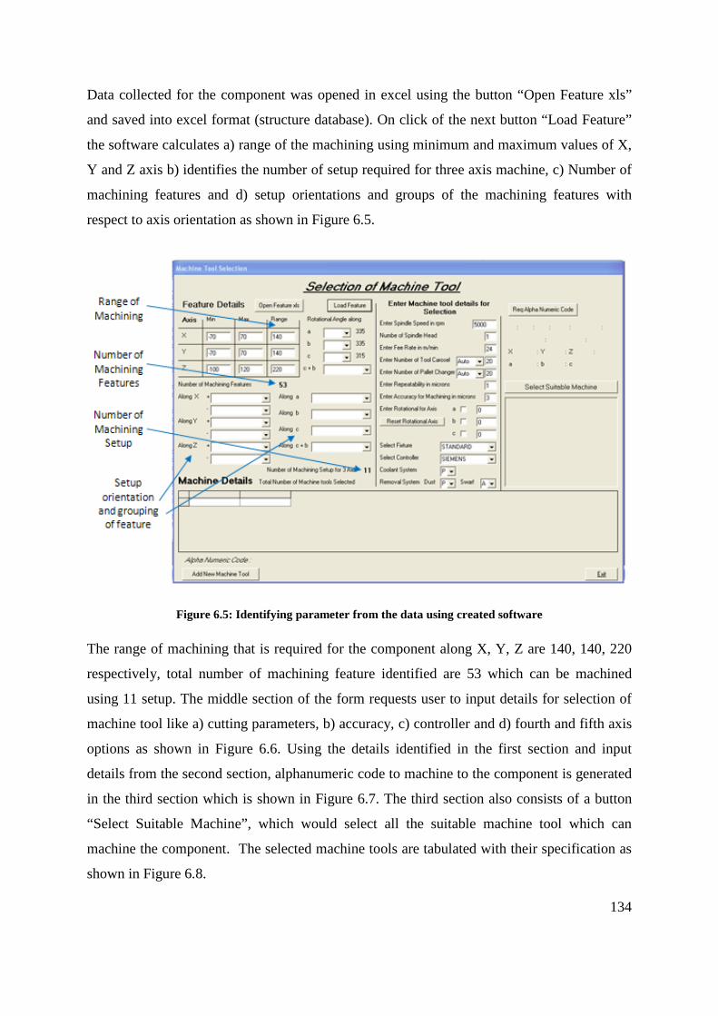
134
Data collected for the component was opened in excel using the button “Open Feature xls”
and saved into excel format (structure database). On click of the next button “Load Feature”
the software calculates a) range of the machining using minimum and maximum values of X,
Y and Z axis b) identifies the number of setup required for three axis machine, c) Number of
machining features and d) setup orientations and groups of the machining features with
respect to axis orientation as shown in Figure 6.5.
Figure 6.5: Identifying parameter from the data using created software
The range of machining that is required for the component along X, Y, Z are 140, 140, 220
respectively, total number of machining feature identified are 53 which can be machined
using 11 setup. The middle section of the form requests user to input details for selection of
machine tool like a) cutting parameters, b) accuracy, c) controller and d) fourth and fifth axis
options as shown in Figure 6.6. Using the details identified in the first section and input
details from the second section, alphanumeric code to machine to the component is generated
in the third section which is shown in Figure 6.7. The third section also consists of a button
“Select Suitable Machine”, which would select all the suitable machine tool which can
machine the component. The selected machine tools are tabulated with their specification as
shown in Figure 6.8.

135
Figure 6.6: Second section to request user to input details for machine tool selection
Figure 6.7: Section three of the software created using Visual Basic

136
Figure 6.8: List of suitable machine tools selected
6.4 Optimal Choice from Machine tool Database
Selection of the optimal choice of machine tool for the component is really important as the
selection process of a machine tool has been a critical issue for companies. Improper
selection of a machine tool might cause many problems having a negative effect on
productivity, precision, flexibility, and a company's responsive manufacturing capabilities.
Present system of selection of machine tool would either use a matrix method [78-81] or a
database [82] for selection. Methods [78-81] uses features of machine tool for selection were
as the component details are not matched in the selection process. The created software inter-
relates the components specification and matches to the machine tools features. This not only
benefits a vendor to outsource a component by machining the optimal machine tool, but also
reduces the confusion and timing for the selection of machine tool.
6.4.1 Choice of 3-Axis Machine Tool
The component analyzed in the Figure 6.1 for the case study would require up to 11 setups to
complete the various machining features on a three traverse axis of a machine tool. The setup
would require stopping the machining process, de-clamping the component and res-position
the component to a different orientation of machining. The various setups required to

137
complete the process is identified and populated into combo box of axis as shown in Figure
6.9 and various setup required from initial datum setup are tabulate in the Table 6.8.
Figure 6.9: Identified Machining Features populated along the axis
Table 6.8: Setup angle and number of Setups
Along Axis Setups Angle Number of Setup +Z Initial Datum Setup 1st -Z YES 2nd a 25deg, 335deg 3rd and 4th b 25deg, 335deg 5th and 6th c 135deg, 315deg 7th and 8th
c + b 135+45deg, 315+45deg, 315+48deg
9th , 10th and 11th
Further with the details entered by the user, optimal choice of machine tool for three axes are
selected from the database and populated in a table as shown in Figure 6.10.
Figure 6.10: Suitable Three Axes Machine Tool Selection
Three axis machine tool’s work space is cuboids, around which the cutter can reach by
moving independently or simultaneously along the axes. Maximum capacity along the three
transverse axis is identified using the range calculated using the created software. Presence of
machining feature along any other orientation other than positive Z axis would require
changing the orientation of the machining feature along positive Z axis. Setting the
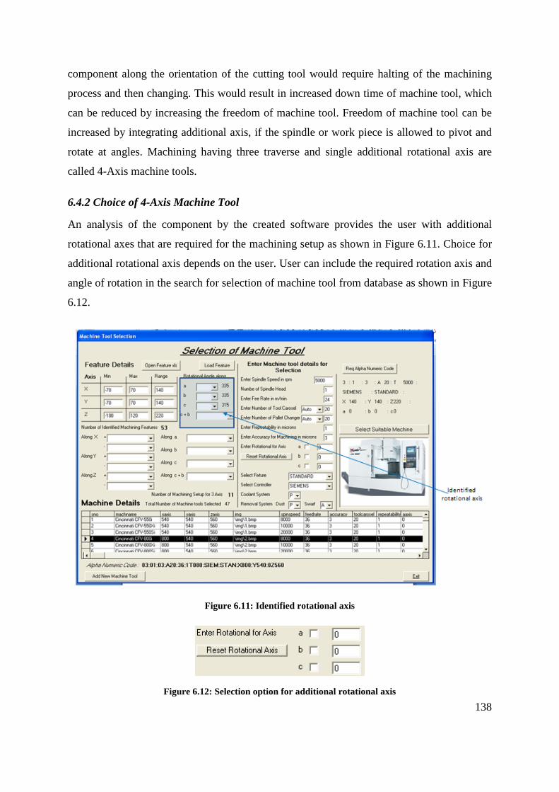
138
component along the orientation of the cutting tool would require halting of the machining
process and then changing. This would result in increased down time of machine tool, which
can be reduced by increasing the freedom of machine tool. Freedom of machine tool can be
increased by integrating additional axis, if the spindle or work piece is allowed to pivot and
rotate at angles. Machining having three traverse and single additional rotational axis are
called 4-Axis machine tools.
6.4.2 Choice of 4-Axis Machine Tool
An analysis of the component by the created software provides the user with additional
rotational axes that are required for the machining setup as shown in Figure 6.11. Choice for
additional rotational axis depends on the user. User can include the required rotation axis and
angle of rotation in the search for selection of machine tool from database as shown in Figure
6.12.
Figure 6.11: Identified rotational axis
Figure 6.12: Selection option for additional rotational axis

139
The rotational axis can be provided by a, b or c, along X, Y or Z respectively which can
orient the component in additional direction to reduce setups. Additional rotational axis a, b
and c can provide setup for machining feature which orient between XZ, YZ, and XY axes
respectively. Rotational axis c is not a preferred axis as the component does not provide any
change in the orientation of the component. Conjunctions of c rotation with any other
rotational axis creating the 5-axis machine are useful for orientation. Figure 6.13 illustrates
the reduction of setup for machining the component with inclusion additional rotational axis
along a, b, or c.
Inclusion of an axis Along Axis Setups Angle Number of Setup
+Z Initial Datum Setup 1st -Z YES 2nd a 25deg, 335deg 3rd b 25deg, 335deg 4th and 5th c 135deg, 315deg 6th and 7th
c + b 135+45deg, 315+45deg, 315+48deg
8th , 9th and 10th
Inclusion of b axis
Along Axis Setups Angle Number of Setup +Z Initial Datum Setup 1st -Z YES 2nd a 25deg, 335deg 3rd and 4th b 25deg, 335deg 5th c 135deg, 315deg 6th and 7th
c + b 135+45deg, 315+45deg, 315+48deg
8th , 9th and 10th
Inclusion of c axis
Along Axis Setups Angle Number of Setup +Z Initial Datum Setup 1st -Z YES 2nd a 25deg, 335deg 3rd and 4th b 25deg, 335deg 5th and 6th c 135deg, 315deg 7th
c + b 135+45deg, 315+45deg, 315+48deg
8th , 9th and 10th
Figure 6.13: Reduction of setup with inclusion of single rotary axis

140
6.4.3 Choice of 5-Axis Machine Tool
Inclusion of two rotational axis Along Axis Setups Angle Number of Setup
+Z Initial Datum Setup 1st -Z YES 2nd a 25deg, 335deg 3rd b 25deg, 335deg 4th c 135deg, 315deg 5th
c + b 135+45deg, 315+45deg, 315+48deg
6th
Figure 6.14: Reduction of setup with inclusion of single rotary axis
Additional axes combination ab, bc, or ca can be included to existing 3 axis setup for a 5-axis
machine tool to reduce the number of setup. Figure 6.14 shows the possible 5 axis
combinations and their setups.
6.5 Working of Soft wares
The Figure 6.15 shows the Pro/Engineering application for CAD modelling. Created software
is invoked within the application using the sub-menu “Auxiliary application” which is under
main menu option of “Tools” as shown in Figure 6.16. The selection of the menu will open
up a new window called “Auxiliary Applications” window as shown in Figure 6.17.

141
Figure 6.15: Pro/Engineer Application for CAD modelling

142
Figure 6.16: Invoking created software using Auxiliary Applications
Figure 6.17: Auxiliary Application window
Using the auxiliary application’s window the created registry file is opened using the register
button as shown in Figure 6.18 which links the created software with Pro/Engineering

143
application. After locating the registry file, the file is started using the stop/start button on the
window as shown in Figure 6.19 and Figure 6.20 shows the application running.
Figure 6.18: Opening the registry file using auxiliary applications
Figure 6.19: Start/Stop of registry file

144
Figure 6.20: Running of the registry file in Auxiliary Application window
Once the registry file link’s the created software with the Pro/Engineering application a new
menu called “Machining Features” with its sub-menu are created next to “Help” menu as
shown in Figure 6.21. The created menu has the sub menus of the entire machining feature
that are created using in the API software and finally included a menu called “Select
Machine”. On selection of the sub menu to identify a specific machining feature, the API
software would highlight the edges of surfaces which create the machining feature as shown
in Figure 6.22. Highlighted surfaces are selected and accepted using the select window as
shown in Figure 6.23. Further instance of the machining feature is highlighted and the
procedure is repeated until all the requested machining features are highlighted. The surface
selected are passed on to various Pro/TOOLKIT functions to identify the data required, which
are stored into flat file database.

145
Figure 6.21: Machining Features menu and its sub menu
Figure 6.22: Machining feature highlighted
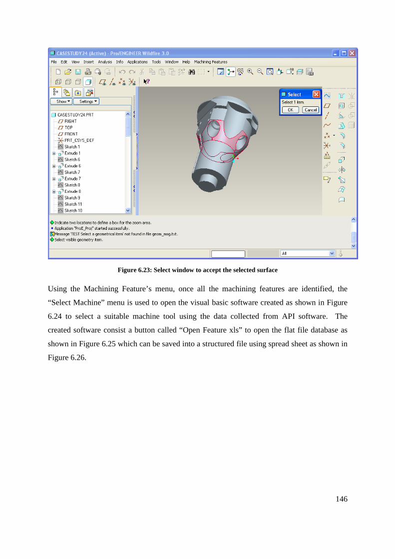
146
Figure 6.23: Select window to accept the selected surface
Using the Machining Feature’s menu, once all the machining features are identified, the
“Select Machine” menu is used to open the visual basic software created as shown in Figure
6.24 to select a suitable machine tool using the data collected from API software. The
created software consist a button called “Open Feature xls” to open the flat file database as
shown in Figure 6.25 which can be saved into a structured file using spread sheet as shown in
Figure 6.26.

147
Figure 6.24: Visual Basic Software Created for Selecting Machine Tool
Figure 6.25: Flat file database saved as Structure database

148
Figure 6.26: Saving Flat file to structure database
The next button called “Load Feature” which will analysis the database and identify a) range
of machining, b) machining feature’s orientations, c) number of machining features, and c)
number of setup required for machining. The identified details are shown in Figure 6.27.
Figure 6.27: Identified details from structure data
The next section of the software separated using two vertical lines request the user to input
further machining details. The button “Req Alpha Numeric Code” will now generated a
alphanumeric code specific for the component with request machining details and is given as

149
output as shown in Figure 6.28. On Click of button “Select Suitable Machine” the optimal
machines which match the requirements are selected using generated alphanumeric code. The
Figure 6.29 shows the selected machine tool which are tabulated with their specifications.
Figure 6.28: Generation of Alphanumeric code for the component

150
Figure 6.29: Selection of suitable machine tool using alphanumeric code
Figure 6.30: Window to add new machine tool to the database
Using the button “Add New Machine Tool” new machine tool can be added to the database.
On click of the button a new window called “Enter Machine Tool Details” is opened which

151
will request user to input details of machine tools as shown in Figure 6.30. The Window also
provides further option to browse, modify and delete machine tools in the database

152
Chapter 7 – Summary and Conclusion
7.1 Summary
Machine Tools have been analysed with due considerations for axes, sizes, spindles, tool
magazines, palettes and controllers. Their structural layout has been analysed based on the
block structure method. Using the results of these analysis an alphanumeric code to uniquely
represent a machine tool has been developed.
Machine tools available in the market have been analysed and alphanumeric codes for them
have been developed and stored in a sample database. The database can be browsed and
machine tools with chosen alphanumeric codes can be retrieved for detailed viewing.
A system has been established with Pro/Engineer software suite from which machining
features and relevant information from a CAD model produced by Pro/Engineer can be
extracted. A software written in ‘C’ has been developed using the API, Pro-toolkit for this
extraction of information. A software system has been established to choose required
machine tool using their characteristics machining features generated as alphanumeric code
for the given machining job. Finally, a software incorporating the above and the required
interfaces for inputting and outputting has been established. The software has been tested
with several case studies and proven to be effective.
7.2 Contribution
Major Contributions of this research work are:
• Machine tools features such as axes, sizes, spindles, tool magazine, pallets, controller
etc were identified to created alphanumeric strings which were in turn used for
generation of alphanumeric code.
• Database of commercially available machine tools consisting of their machining
features was created and generated alphanumeric code was also included.
• A bolt on software to Pro/Engineer was created using C program to identify the
machining features and its parameters.

153
• Identified machining features and its parameters, along with required machining
details of a component was used to generate alphanumeric code for any arbitrary
component.
• Both the alphanumeric code was matched to select a suitable machine tool which was
implemented using visual basic.
7.3 Limitation
• The selection of suitable machine tool is limited to vertical milling machine and its
jobs.
• Database of machining tool is limited in this work, for commercial viability of the
process, database has to be extensively populated.
7.4 Further Research
• Machining Features, which are identified, can be sequenced in order of priority for
machining.
• With inclusion of cutting tool information, creating NC code using CAM can also be
incorporated, as the parameters of the machining features are readily available.
• The selection process can further be extended to Turning centres and other types of
milling machine with modification in the software.
• Use of feature information for cost estimation and to provide feed-back about
consequences of design decisions can be implemented for selection of outsourcing job.

154
Bibliography
[1] Briggs H, (March, 2000). Emerging Global Manufacturing Trends, Work Session informan 2000, Institute for Manufacturing, University of Cambridge, pp. 1-27 [2] Berggren C, Bengtsson L, (2004). Rethinking outsourcing in manufacturing: A tale of two telecom firms, European Management Journal, 22(2), pp. 211–223 [3] Steeds Willaim. (1969). A History of Machine Tools 1700-1910. Clarendon Press.
[4] What is a Machining Centre? (1967, Feb). Machinery and Production Engineering , 339.
[5] Vargov Yu D, (1968). Operation Classification of Machine Tools. Machines & Tooling ,
XL (4), pp. 5-10.
[6] Portman V T, (1982). Synthesis of Machine Tool Configuration Based on an Analysis of
the Form Generation Process Issue. Stanki i Instruments , 53 (7), pp. 8-11.
[7] Voronov A L, (1978). Structure and Coding of Configuration of NC Machine Tools .
Stanki i Instrument , 49 (10), pp. 3-5.
[8] Ito Y, Shinno H, (1982). Structural Description and Similarity Evaluation of the Structural
Configuration in Machine Tools. Machine Tool Design , 22 (2), pp. 97-110.
[9] Roth - VP Ingersoll Machine Tools. (2006). Machine Tool Development and Automation.
(Lecture in Brunel University).
[10] Ito Y, Shinno H, (1981). Structural Description of Machine Tools – I, Description
Method and Some Application. JSME , 24 (187) pp. 251-258.
[11] Ito Y, Shinno H, (1981, Jan). Structural Description of Machine Tools – II, Evaluation of
Structural Similarity. JSME , 24 (187), pp. 259-265.
[12] Khomyakov V S, Davydov I I, (1989). Coding of Machine Layouts for Computer-Aided
Design Work, Soviet Engineering Research, 9(9), pp 79-84.
[13] Vargov Yu D, (1972). Structural Analysis of Machine Tool Layout. XLIII (8), pp. 5-8.

155
[14] Khomyakov V S, Davydov I I, (1990). Computer Aided Design of Machine Tool
Layouts. Stank i Instruments , 61 (5), pp. 4-7.
[15] Ito Y, Shinno H, (1982). Structural Description and Similarity Evaluation of the
Structural Configuration in Machine Tools. Machine Tool Design , 22 (2), pp. 97-110.
[16] Ito Y, Shinno H, (1984). A Proposed Generating Method for the Structural
Configuration of Machine Tools. 84-WA/ (Prod-22).
[17] Jami J S, Martti M, (1995). Parametric and feature-based CAD/CAM: concepts,
techniques, and applications. John Wiley & Sons Inc
[18] Jami J S, Palat S, Abraham M, (1991, Feb). Survey of CAD/Feature Based Process
Planning and NC Programming Techniques, . Computer-Aided Engineering Journal , pp. 25-
33.
[19] Jami J S, Martti M, (1994). A Methodology for Systematic Generation and Evaluation
of Alternative Operation Plans. Advances in feature based Manufacturing , pp. 161 –184.
[20] Joshi S, Chang T C, (1988). Graph based heuristics for recognition of machined features
from a 3D solid model. Computer-Aided Design, 20(2), pp. 58-66
[21] Marefat M, Kashyap R L, (1990). Geometric reasoning for recognition of three-
dimensional object features. IEEE Transaction on Pattern Analysis and Machine Intelligence,
12(10), pp. 949-965.
[22] Trika S N, Kashyap R L, (1993). Geometric reasoning for extraction of manufacturing
features in isooriented polyhedrons. IEEE Transaction on pattern Analysis and Machine
Intelligence, 16(11), pp. 1087-1100.
[23] Ji Q, Marefat M, Leve P J, (1995). An evidential reasoning approach for recognizing
shape feature. In Proceeding of the 11th IEEE conference on AI for application.
[24] Meeran S, Pratt M J, Kay J, (1993). The use of PROLOG in the automatic recognition of
manufacturing features from 2-D drawings, Engineering Application Artificial Intelligence ,
6(5), 409-423

156
[25] Meeran S, Pratt M J, (1993). Automated feature recognition from 2D drawings.
Computer Aided Design, 25(1), pp. 7-17
[26] Meeran S, Taib J. M. (1999). A generic approach to recognizing isolated, nested and
interacting features from 2D drawing. Computer Aided Design, 31(14), pp. 891-910
[27] Vandenbrande J H, Requicha A A G, (1989). Form Features for Mechanical Design and
Manufacturing, Proceeding of the International Computers in Engineering Conference and
Exhibition, pp. 47-52.
[28] Vandenbrande J H, Requicha A A G, (1990). Spatioal Reasoning for Automatic
Recognition of Interacting Form Features, Proceedings of the 1990 ASME International
Computers in Engineering Conference and Exposition, pp 251-256
[29] Vandenbrande J H, Requicha A A G, (1993). Spatial reasoning for the automatic
recognition of machinable features in solid models. IEEE Transaction on Pattern Analysis
and Machine Analysis, 15(12), pp.1269-1285
[30] Henderson M R, Srinath G, Roger S, Walker K, Regli W, (1994). Boundary
representation-based Feature Identification. In Advances in Feature Based Manufacturing,
Shah J. J, Mantyla M, Dana S.N. (eds.). Elsevier Science Ltd.
[31] Preiss K, Kaplansky E, (1983). Automatic Mill Routing from solid geometry
information. Warman, E a (ed) Proc. 1st Int. IFIP Conf. Computer-Applications in
Production and Engineering Amsterdam: Netherlands
[32] Choi B K, Barash M M, Anderson D C, (1984). Automatic Feature Recognition of
machined surfaces from a 3D solid model. Computer-Aided Design. 16(2), pp. 81-86
[33] Henderson M R, Anderson D, (1984). Computer recognition and extraction of form
feature. Computer in Industry. (4), pp. 329-339.
[34] Nnaji B O, and Liu H C, (1990). Feature reasoning for automatic robotic assembly and
machining in polyhedral representation. International Journal of Production Research. 28,
pp. 517 – 540

157
[35] Raymond C W S, Corney J S, Clark D E R, (2000). Octree Based Recognition of
Assembly Features. Proceeding of DETC’00: ASME 2000 Design Engineering Technical
Conferences and Computers and Information in Engineering Conference. Sept. 10-13
Baltimore: Maryland, pp. 1-10
[36] Gao S, Shah J J. (1996). Automatic Recognition of interacting machining features based
on minimal condition subgraph. Computer Aided Design, 30(9), pp. 727-739
[37] Kyprianou L, (1980). Shape classification in computer aided design, PhD Dissertation,
University of Cambridge
[38] Kim Y S, Wang E, Hwang I K, Rho H M, (2001). Geometry-Based Machining
Precedence Reasoning for Feature-Based Process Planning, International Journal of
Production Research, 39(10), pp. 2077-2103
[39] Woo T C, (1982). Feature extraction by volume decomposition. In Proceedings of
Conference on CAD/CAM Technology in Mechanical Engineering, MIT Press, Cambridge,
USA, pp. 76-94
[40] Little G, Clark D E R, Corney J R, (1998). Tuttle JR. Delta Volume decomposition for
multi-sided components. Computer Aided Design, 30(9), pp. 695-705
[41] Han J, Pratt M, Regli W, (2000). Manufacturing feature recognition from solid models: a
status report, IEEE Trans Robot Automat 2000, 16(60), pp. 782-796
[42] Owudunni O, Hinduja S, (2002). Evaluation of exisiting and new feature recognition
algorithms Part 1. Theory implementation. Proc Isnt Mech Engrs, J Engng Manufact,
216(partB), pp. 839-851.
[43] Gupta S K, Kramer T R, Nau D S, Regli W C, Zhang G, (1994). Building MRSEV
Models for CAM Applications, Advances in Engineering Software, 20(2/3), pp. 121 - 139.
[44] Regli, W C, Gupta S K, Nau D S, (1994). Feature recognition for manufacturability
analysis. ASME International Computers in Engineering Conference, Minneapolis.
[45] Regli W C, (1995). Geometric algorithms for recognition of features from solid models,
PhD Thesis, The University of Maryland, College Park MD.

158
[46] Woo Y, Sakurai H, (2002). Recognition of maximal features by volume decomposition.
Computer Aided Design, 34(3), pp. 195-207
[47] Huang Z, Yop-Hoi D, (2002). High-level feature recognition using feature relationship
graphs. Computer Aided Design, 34(8), pp. 561-582
[48] Liu Z, Wang L, (2007). Sequencing of interacting prismatic machining features for
process planning. Computers in Industry, 58, 295-303
[49] Abouel Naser E S, Kamarani A K, (2006). A new methodology for extracting
manufacturing features from CAD system. Comput Ind Eng, 51(3), pp. 389-415
[50] Aslan E, Seker U, Alpdemir N, (1999). Data extraction from CAD model for rotational
parts to be machined at turning centers. Turkish Journal of Engineering and Environmental
Science, 23(5), pp. 339-347
[51] Lee J Y, Kim K, (1998). "A feature-based approach to extracting machining features",
Computer Aided Design, Vol. 30 No.13, pp.1019-35
[52] Huang Z, Xie B, Ma L, Wei X, (2006). Feature conversion based on decomposition and
combination of swept volumes. Comput Aided Des 38, pp. 857–873
[53] Li W D, Ong S K, Nee A Y, (2002). Recognizing manufacturing features from a design-
by-feature model. Comput Aided Des, 34, pp. 849–868
[54] Sadaiah M, Yadav D R, Mohanram P V, Radhakrishnan P A, (2002). Generative
computer-aided process planning system for prismatic components. Int J Adv Manuf Technol,
20, pp. 709–719
[55] Arivazhagan A, Mehta N K, Jain P K, (2009). A STEP AP 203–214-based machinable
volume identifier for identifying the finish-cut machinable volumes from rough-machined
parts. Int J Adv Manuf Technol, 42, pp. 850–872
[56] Lee H C, Jhee W, Park H S, (2007). Generative CAPP through projective feature
recognition. Computers & Industrial Engineering, 53(2), pp. 241-246
[57] Tseng Y L, Joshi S B, (1994). Recognizing multiple interpretations of interacting
machining features. Computer-Aided Design, 26(9), pp. 667-688

159
[58] Prabhakar S, Henderson M R, (1992). Automation Form Feature Recognition Using
Nueral Network Based Techniques on Boundary Representation of Solid Models, Computer
Aided Design, 24(7), pp 381-393
[59] Ding L, Yue Y, (2004). Novel ANN-based feature recognition incorporating design by
features, Comput Ind, 55(2), pp. 197-222
[60] Chan C C H, (1994). ANN Based feature recognition and grammar based feature
extraction to integrate design and manufacturing, PhD thesis, University of Iowa, USA
[61] Ozturk N, Ozturk F, (2001). Neural network based non standard feature recognition to
integrate CAD and CAM, Computers in Industry, 45, pp. 123-135
[62] Yue Y, Ding L, Ahmet K, Painter J, Walter M, (2002). Study into neural network
techniques for computer integrated manufacturing. Engineering Computation, 19, pp. 136-
159.
[63] Marafat M M, Pitta C, (2007). Similarity-Based Retrieval of CAD Solid Models for
Automated Reuse of Machining Process Plans, Proceeding of the £rd IEEE CASE, pp. 312-
317
[64] Ibrahim R N, McCormack A D, (2002). Process planning using adjacency-based feature
extraction. International Journal of Advanced Manufacturing Technologies, 20(11), pp. 817–
823
[65] Ibrahim, R. N, McCormack, A. D, (2005), Robustness and generality issues of feature
recognition for NC machining. International Journal of Advanced Manufacturing
Technologies, 25(7-8), pp. 705–703
[66] Li W D, Ong S K, Nee A Y C, (2003). A hybrid method for recognizing interacting
machining features. Int J Prod Res, 41, pp. 1887-1908
[67] Zhang C, Chan K W, Chen Y H. (1998). A hybrid method for recognizing feature
interactions. Comput Integr Manuf Sys, 9, pp. 120-128
[68] Beg J, Shunmugam M S, (2002). An object oriented planner for inspection of prismatic
parts OOPIPP. Int J Adv Manuf Technol, 19(1), pp. 905-916

160
[69] Rameshbabu V, Shunmugam M S, (2009). Hybrid feature recognition method for setup
planning from STEP AP-203. Robotics and Comput Int Manuf , 25, pp. 393-408
[70] Dimov S S, Brousseay E B, Setchi R, (2007). A hybrid method for feature recognition
in computer-aided design models. Proceeding of the Instution of Mechanicla Engineers, Part-
B: Journal of Engineering Manufacturing, 221(1), pp. 79-96
[71] Pal P, Kumar A, (2002). A hybrid approach for identification of 3D features from CAD
database for manufacturing support. International Journal of Machine Tools & Manufacture,
42, pp. 221–228
[72] Karinthi R R, (1990). An algebraic approach to feature interactions, PhD thesis,
Computer Science Department, University of Maryland, College Park MD,
[73] Chitroda M, Sivaloganathan S, (2007). Adequacy of machining features for describing
machining jobs, International Journal of Industrial and Systems Engineering, 2(2), pp. 211-
229
[74] Srikumaran S, (2005). Ensuring Manufacturability Through Feature Mapping, PhD
Thesis, Brunel University, Department of Design and Systems Engineering, UK
[75] Sirkumaran S, Sivaloganathan S, (2005). Proving manufacturability at the design stage
using commercial modeling Software: Through feature mapping and feature Accessibility,
Computer Aided Design & Applications, 1-4 (2), pp. 507-516.
[76] BS Standards, (1992). Accuracy of Machine Tools and Methods, BS4656-30, BSI.
[77] Cimren E, Catay B, Budak E, (2007). Development of Machine Tool Selection System
Using AHP, International Journal of Advanced Manufacturing Technology, 35(3-4), pp.
363-376
[78] Tlusty G, (2000). Manufacturing Process and Equipment, Prentice Hall
[79] Kalpakjian S, Schmid S R, Kok C W, (2001). Manufacturing Engineering and
Technology, Prentice Hall

161
[80] Kamhawai H N, Leclair S R, Chen C L P, (1996). Feature Sequencing in the Rapid
Design System Using a Generic Algorithm, Journal of Intelligent Manufacturing, 7(1), pp.
55-67
[81] Ic Y T, Yurdakul M, (2009). Development of Decision Support System for Machining
Center Selection, Expert systems with Applications, 36(2/2), pp. 3305-3513
[82] Vasilash G S, (1997). Machine Tool Selection Made Simple, Automotive Manufacturing
& Production, 109(3), pp.66-67
[83] Sato M, (2006). Design and Performance of 5-Axis Machines in Japan, Proceeding of
12th International Conference on Machine Tool Engineer’s, pp. 167-189
[84] Moriwaki T, (2008). Multi-Functional Machine Tool, Manufacturing Technology, 57,
pp. 736-749
[85] Iredale R, (1965). Tomorrow’s Method for Machine Tool Manufacture – Today,
Metalworking Production, pp. 67-70
[86] What is Machining Centre? (1967, Feb). Machinery and Production Engineering, pp.
339
[87] Bawa H S, (2004). Manufacturing Processes, Tata McGraw Hill.