optics isat 241 analytical methods iii fall 2003 david j. lawrence
TRANSCRIPT
OpticsOptics
ISAT 241
Analytical Methods III
Fall 2003
David J. Lawrence

Light as a WaveLight as a Wave Wavemotion (propagation) of a
disturbance. Waves transport energy. Mechanical waves
sound, earthquakes, and ocean waves require a “medium” that can be disturbed.
Light and radio waves are examples of “Electromagnetic waves”. Disturbance is variations in electric (E) and
magnetic (B) fields. Since E and B can exist in a vacuum,
electromagnetic waves do not require a medium.

For a “Harmonic Wave” (sinusoidal wave)
Wave speed = frequency x wavelength
v fFor light and other “Electromagnetic Waves”, in a vacuum:
v = c = 2.9979 108 m/sIn air:
vair = 2.9970 108 m/s
In glass:vglass = 2.0 108 m/s~
1 nanosecond = 1 ns = 1 x 10⁻⁹ s= one billionth of a second
In 1 ns, light travels a distance of:
d = (3 108 m/s) (1 10-9 s) = 0.3 m = 1 ft~
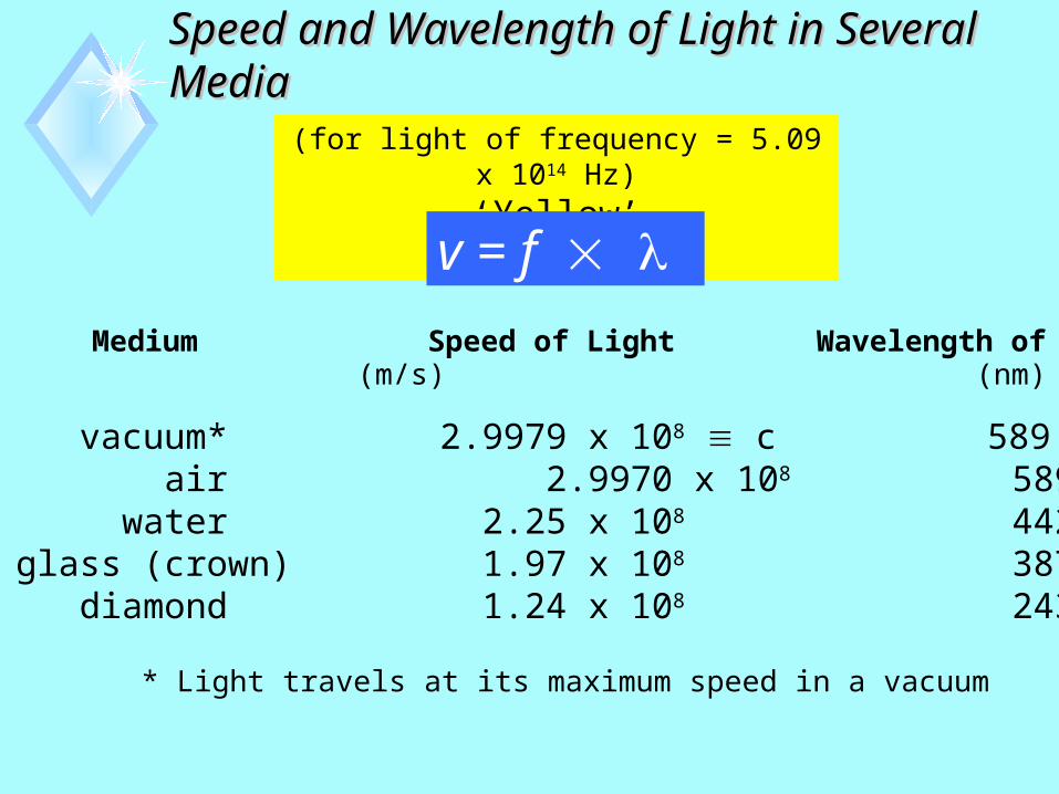
Speed and Wavelength of Light in Several MediaSpeed and Wavelength of Light in Several Media
(for light of frequency = 5.09 x 10¹⁴ Hz)
‘Yellow’
v = f Medium Speed of Light Wavelength of Light
vacuum* 2.9979 x 10⁸ c 589 air 2.9970 x 10⁸ 589 water 2.25 x 10⁸ 442glass (crown) 1.97 x 10⁸ 387 diamond 1.24 x 10⁸ 243
(m/s) (nm)
* Light travels at its maximum speed in a vacuum

c f For the visible portion of the spectrum, the wavelength in vacuum (or in air) ranges from:
nm to nm
Å to Å
Color f (Hz)(nm)
red 630-760 4.5 x 10¹⁴
orange 590-630 4.9 x 10¹⁴
yellow 560-590 5.2 x 10¹⁴
green 500-560 5.7 x 10¹⁴
blue 450-500 6.3 x 10¹⁴
violet 380-450 7.1 x 10¹⁴
These are average values!!
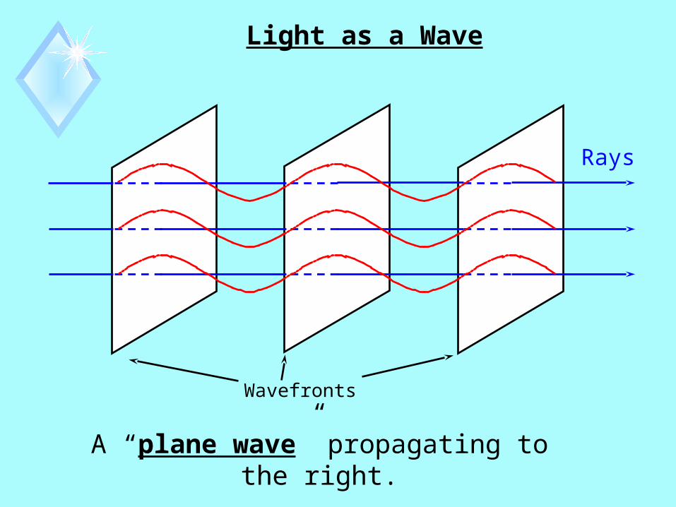
Light as a Wave
Rays
Wavefronts
A “plane wave” propagating to the right.

The Ray Approximation
WavefrontsA plane wave propagating to the right.
Rays
“Rays” are straight lines perpendicular to the wavefronts. They point in the direction of motion of the wave.

Serway & Jewett, Principles of Physics
Figure 25.1

Serway & Jewett, Principles of Physics
Figure 25.2

Serway & Jewett, Principles of Physics
Figure 25.3
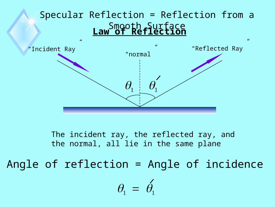
Specular Reflection = Reflection from a Smooth Surface
Law of Reflection
“Incident Ray”
“Reflected Ray”“normal”
The incident ray, the reflected ray, and the normal, all lie in the same plane
Angle of reflection = Angle of incidence
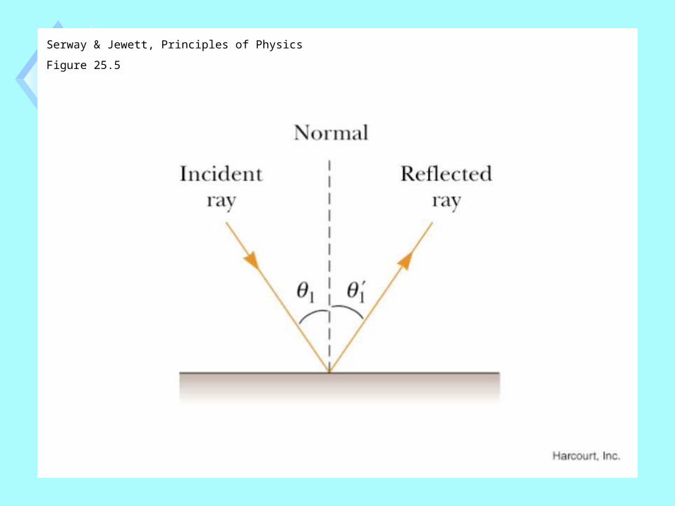
Serway & Jewett, Principles of Physics
Figure 25.5

Consider MRDs marching from afootball field into a swamp . . .
Swamp
v1
Field
v2

The Index of Refraction, n , of a medium is defined as the ratio:
speed of light in a vacuum cn speed of light in the medium =
v
(m/s)
vacuum 2.9979 x 10⁸ 589 1 air 2.9970 x 10⁸ 589 1.000293 water 2.25 x 10⁸ 442 1.333glass (crown) 1.97 x 10⁸ 387 1.52 diamond 1.24 x 10⁸ 243 2.419
Medium Speed of Light Wavelengthof Light (nm)
Index of Refraction, n
n > 1n is dimensionless
These values apply for light of frequency = 5.09 x 10¹⁴ Hz
(‘Yellow’)
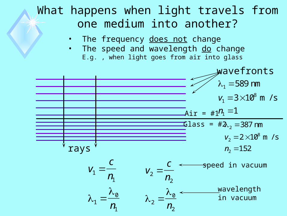
What happens when light travels from one medium into another?
• The frequency does not change• The speed and wavelength do change
E.g. , when light goes from air into glass
rays
Air = #1
Glass = #2
wavefronts1
18
1
589
3 10
1
nm
m / sv
n
2
28
2
387
2 10
152
nm
m / sv
n .
vc
n
n
22
20
2
speed in vacuum
wavelengthin vacuum
vc
n
n
11
10
1
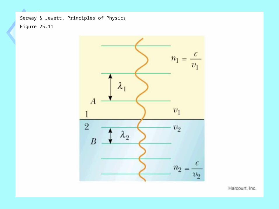
Serway & Jewett, Principles of Physics
Figure 25.11

Field
Swamp
What if columns of MRD’s enter theswamp at an angle?
v1
v2

Refraction of Light
“Reflected Ray”
1
AirGlass
“Incident Ray”
“Refracted Ray”
“normal”
n1
n2
2
1
All rays and the normal lie in the same plane.
The “Refracted Ray” is bent towards the normal.
Law of Refraction - Snell’s Law
n2 > n1
n1 sin = n2 sin

Serway & Jewett, Principles of Physics
Figure 25.8

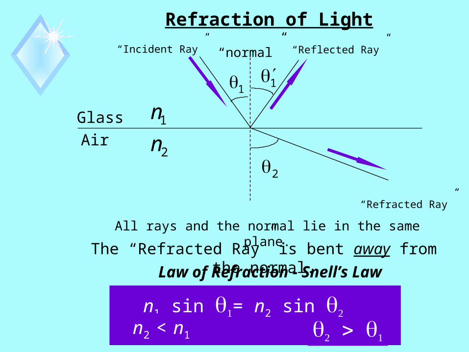
Refraction of Light
Air
“Incident Ray” “Reflected Ray”
“Refracted Ray”
Glass n
n1
2
“normal”
1
2
1
All rays and the normal lie in the same plane.
The “Refracted Ray” is bent away from the normal.
Law of Refraction - Snell’s Law
n1 sin = n2 sin n2 < n1


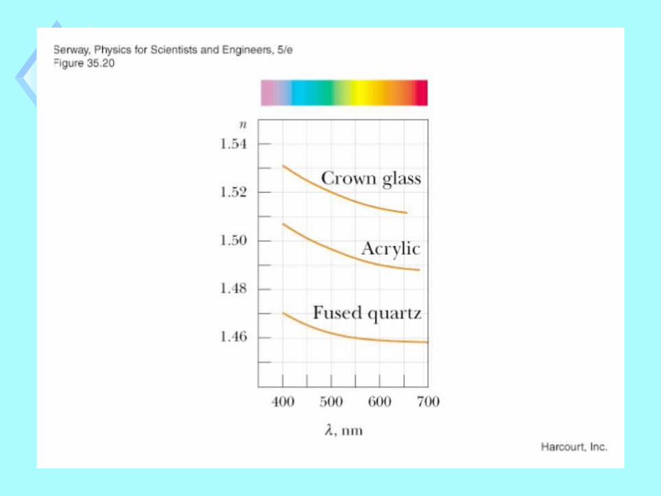
Dispersion
The speed of light in any material depends on the frequency (or wavelength, or color) of the light.
• n depends on wavelength.• Light of different wavelengths will be refracted or bent at different angles when it enters a material.
Therefore:
The material is said to exhibit “Dispersion”
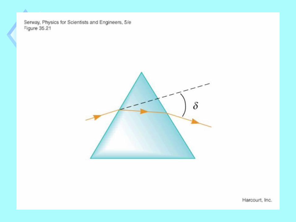
“Normal”
“White light”


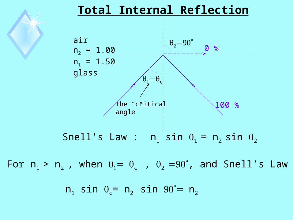
Total Internal Reflection
airn2 = 1.00
n1 = 1.50glass
0 %
c
the “criticalangle”
100 %
Snell’s Law : n1 sin 1 = n2 sin 2
For n1 > n2 , when c , 2 , and Snell’s Law gives
n1 sin c= n2 sin n2

Total Internal Reflection
airn2 = 1.00
n1 = 1.50glass
0 %
c
the “criticalangle”
100 %
angle critical thesin
for sin
1
21
211
2
n
n
nnn
n
c
c
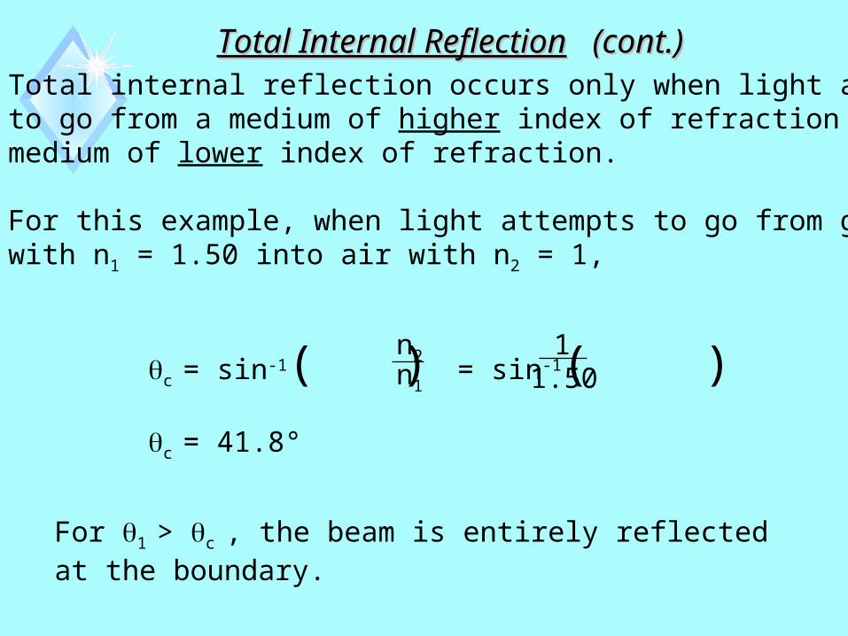
Total Internal ReflectionTotal Internal Reflection (cont.) (cont.)Total internal reflection occurs only when light attemptsto go from a medium of higher index of refraction to amedium of lower index of refraction.
For this example, when light attempts to go from glasswith n1 = 1.50 into air with n2 = 1,
c = sin-1( ) = sin-1( )
c = 41.8°
n2
n1
11.50
For 1 > c , the beam is entirely reflected at the boundary.


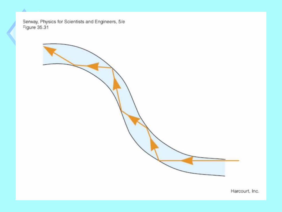
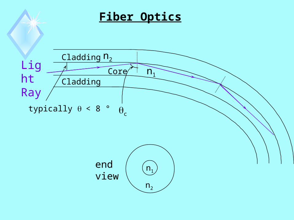
Fiber Optics
end view
n1
n2
Cladding
CladdingCore
c
n1
n2
typically < 8 °
Light Ray

Fiber Optics (cont.)
Light must fall inside this angleto be guided in the fiber core.
2 × Acceptance Angle 2 accept
Acceptance
Angle , acceptair
nair = 1
Core
Cladding
n2
n2
n1c
accept = sin-1 [ n12 - n2
2 ]
Numerical Aperture = NA = sin accept = n12 - n2
2
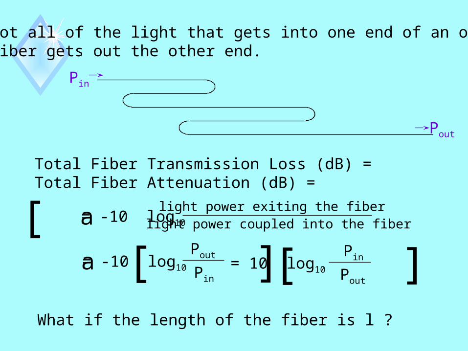
Not all of the light that gets into one end of an opticalfiber gets out the other end.
Pin
Pout
Total Fiber Transmission Loss (dB) =Total Fiber Attenuation (dB) =
= -10 log10[ ]light power exiting the fiberlight power coupled into the fibera
= -10 log10[ ]Pout
Pina = 10 log10 [ ] Pin
Pout
What if the length of the fiber is l ?

Fiber Loss per Unit Length (dB/km)
= Fiber Attenuation per Unit Length (dB/km)
fiber length in km
10l= log10[ ]Pout
Pin
10l
= log10 [ ] Pin
Pout
al
Total Fiber Loss (dB) = Fiber Loss per Unit Length (dB/km) × l (km)
• Accounts for transmission loss in the fiber,
• NOT the losses encountered in getting the light into or out of the fiber (coupling losses).
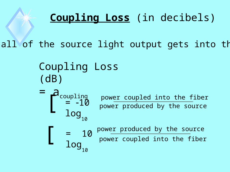
Coupling Loss (in decibels)
Not all of the source light output gets into the fiber.
Coupling Loss (dB)= acoupling
[ ]power coupled into the fiberpower produced by the source= 10 log
10
[ ]power produced by the source
power coupled into the fiber= 10 log
10
Interference of Light WavesInterference of Light Waves “Superposition” In order for us to be able to observe sustained
interference between two or more light waves -(1) The sources of the waves must be
“monochromatic”, which means that they must have a single wavelength (or a single frequency, or a single “color”).
(2) The sources of the waves must be “coherent”, which means that the phase difference between the waveforms must remain constant, e.g.,

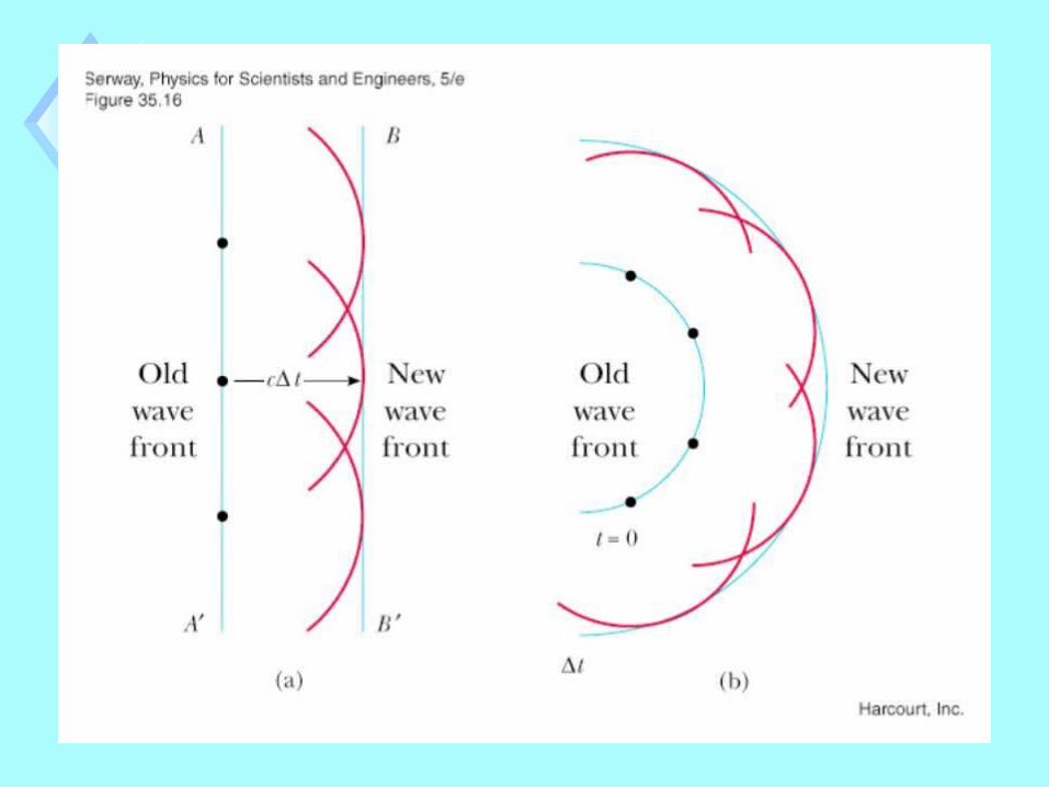
Huygens’ PrincipleHuygens’ Principle
All points on a given wave front are taken as point sources for the production of spherical secondary waves, called wavelets, which propagate outward with speeds characteristic of waves in that medium. After some time has elapsed, the new position of the wave front is the surface tangent to the wavelets.
Page 1119 of the text

Huygens’ PrincipleHuygens’ Principle


Interference of WavesInterference of Waves
Huygen’s Principlep. 1119 of the text
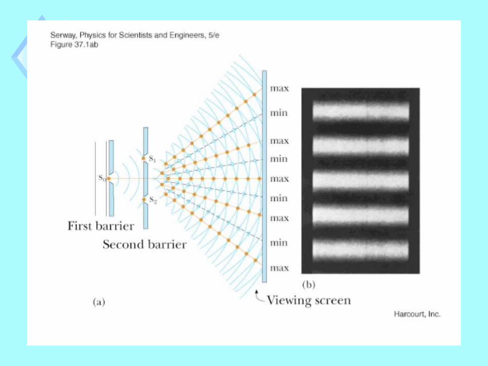

Young’s Double-Slit ExperimentYoung’s Double-Slit Experiment
viewing screen
Sourced
two slits in metal plate
Light exiting the two slits interferes. In Phase Constructive Interference

Young’s Double-Slit ExperimentYoung’s Double-Slit Experiment
Sourced
two slits in metal plate
viewing screen
Light exiting the two slits interferes. Out of Phase Destructive Interference

Young’s Double-Slit ExperimentYoung’s Double-Slit Experiment Light exiting the two slits interferes. Constructive interference bright band
(fringe) Destructive interference dark fringe
Sourced
two slits in metal plate
viewing screen

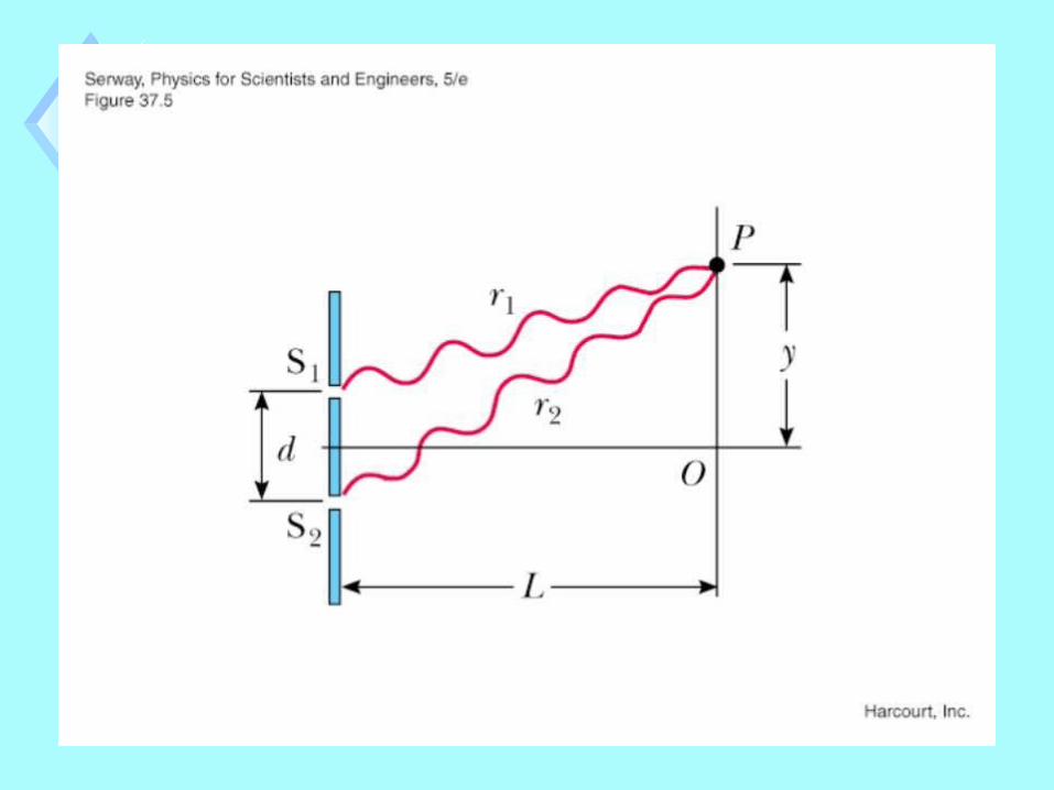
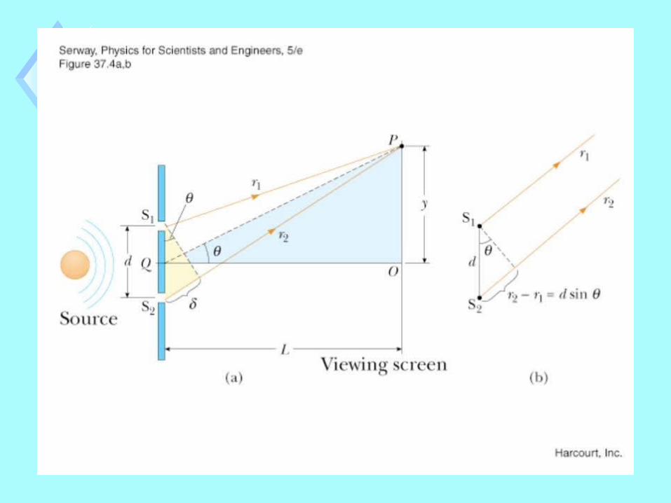

Sourced
P
d sin path difference
r1
r2
Young’s Double-Slit ExperimentYoung’s Double-Slit Experiment In order to have a bright area at point P (called a
“bright fringe” or “constructive interference”), we must have
d sin = m (m = 0, ±1, ±2, ...)

Sourced
P
d sin path difference
r1
r2
In order to have a dark area at point P (called a “dark fringe” or “destructive interference”), we must have
d sin = (m + 1/2) (m = 0, ±1, ±2, …)
Young’s Double-Slit ExperimentYoung’s Double-Slit Experiment
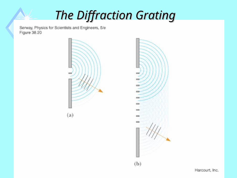
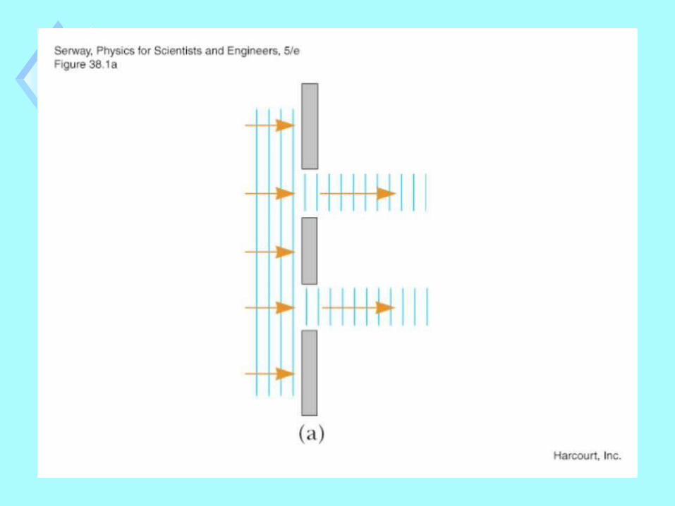
The Diffraction GratingThe Diffraction Grating

The Diffraction GratingThe Diffraction Grating

A diffraction grating consists of a large number of equally spaced parallel slits, e.g., 5000 slits/cm.
Light diffracts (spreads out) as it leaves each slit.Light from each slit interferes with light from the other slits.
Each wavelength experiences constructive interference at a different angle .
blue
red
The Diffraction GratingThe Diffraction Grating

Just as with the double slit, for the diffraction grating we get constructive interference (“maxima” in the interference pattern) when
d sin = m(m = 0, 1, 2, 3, ...)
or sin =md
or = sin-1( )md
e.g., for m=1 and = blue= 475 nm
blue = sin-1 ( )475 nmd
and for m=1 and = red= 660 nm
red = sin-1 ( )660 nmd
red> blue

Interference in Thin FilmsInterference in Thin Films Interference effects are commonly
observed in “thin films”. Examples:
(1) thin layer of oil on water, (2) soap bubbles, (3) coatings on camera lenses and solar cells.
The varied colors observed when white light is incident on a thin film result from the interference of waves reflected from the two surfaces of the film.


Interference in Thin FilmsInterference in Thin FilmsRay 2 reflects off the bottom surface of the film, so it travels 2t farther than ray 1 .
1 2
If the thickness of the film is constant, then for some color (wavelength), rays 1 and 2 will add constructive interference.
For another color (wavelength), rays 1 and 2 will cancel destructive interference.
air n = 1
air n = 1
soap filmn 1.3
t = thickness
In reality, a soap film varies in thickness, so different parts have different colors.


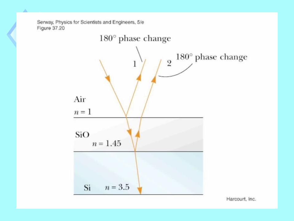
Nonreflective Coatings for Solar CellsNonreflective Coatings for Solar Cells Solar cells
Convert sunlight directly into electricity. Frequently made of silicon.
t = thickness
Air n = 1SiO2
n 1.45
Sin = 3.5
1 2
Often coated with a thin, transparent film Such as silicon dioxide (SiO2).
Reduces the amount of reflected (and hence lost) sunlight.
Ray 2 travels 2t farther than Ray 1 .

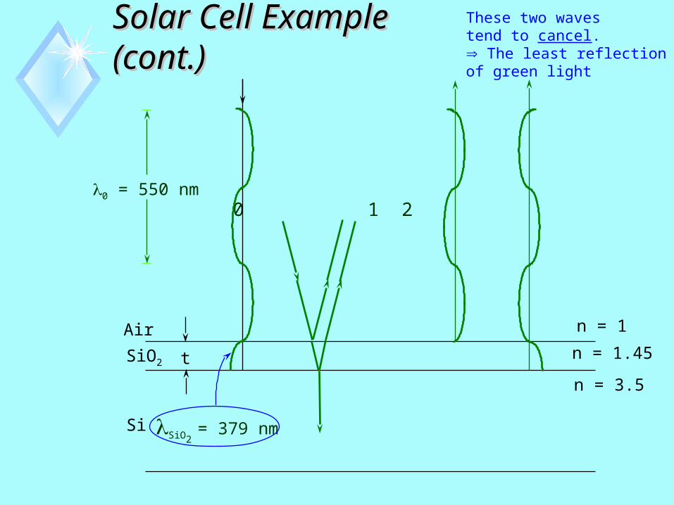
Solar Cell Example (cont.)Solar Cell Example (cont.)
What must the film thickness, t, be so that we will get the least amount of green light (o = 550 nm) reflected from the surface?
The light wavelength inside the SiO2 is
SiO2 = = = 379 nm
o
nSiO2
550 nm1.45
(n = )o
n
Air
SiO2
Si
n = 1
n = 1.45
n = 3.5
0 1 20 = 550 nm
These two wavestend to cancel. The least reflectionof green light
SiO2 = 379 nm
t
Solar Cell Example (cont.)Solar Cell Example (cont.)

Ray 2 travels 2t farther than ray 1, and it does so in SiO2, where
SiO2 =
0
nSiO2
550 nm
1.45= = 379 nm for green light.
In order to make waves 1 and 2 cancel, the path difference, 2t ,
must equalSiO2
2, so we have
2t =SiO2
2
t = = = 94.8 nm SiO2
4
379 nm
4
For an SiO2 coating of this thickness, we get the minimum amount of green light reflected. However, other colors (wavelengths) are reflected.
Solar Cell Example (cont.)Solar Cell Example (cont.)