optics and laser heads for laser-interferometer
TRANSCRIPT

Optics and Laser Heads forLaser-Interferometer Positioning SystemsProduct Overview
Choose from a large selection of optical componentsfor system design
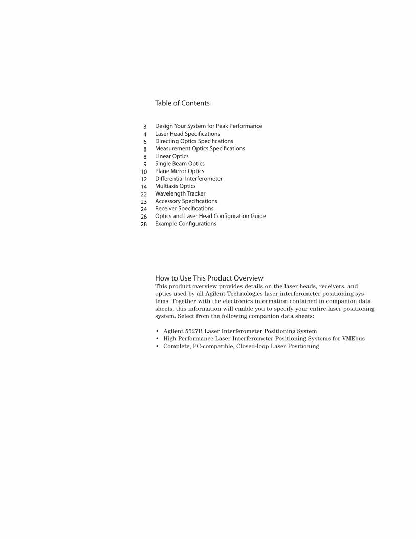
Table of Contents
Design Your System for Peak Performance Laser Head Speci�cationsDirecting Optics Speci�cations Measurement Optics Speci�cationsLinear Optics Single Beam Optics Plane Mirror Optics Di�erential Interferometer Multiaxis Optics Wavelength Tracker Accessory Speci�cations Receiver Speci�cations Optics and Laser Head Con�guration Guide Example Con�gurations
How to Use This Product OverviewThis product overview provides details on the laser heads, receivers, andoptics used by all Agilent Technologies laser interferometer positioning sys-tems. Together with the electronics information contained in companion datasheets, this information will enable you to specify your entire laser positioningsystem. Select from the following companion data sheets:
• Agilent 5527B Laser Interferometer Positioning System• High Performance Laser Interferometer Positioning Systems for VMEbus• Complete, PC-compatible, Closed-loop Laser Positioning
346889
1012142223242628

Measurement
Compensa
Laser Head
Optics • Directing • Measurement
Object Under Control
• Power Amplifier • Drive Motor • Servo-Loop Compensation
Host Computer
Compensa
Laser Head
Optics • Directing • Measurement
Object Under Control
• Power Amplifier • Drive Motor • Servo-Loop Compensation
Host Computer
Ele
Measurement
Compensation
MeasurementReceivers
EnvironmentalSensors
tion
MeasurementReceivers
ctronics
EnvironmentalSensors
tion
PowerSupply
3
The wide variety of optics and laserheads from Agilent gives you maxi-mum design flexibility to achieve yourperformance goals.
In addition to a full range of con-ventional optics, multiaxis optics pro-vide new possibilities for extremelyaccurate positioning system designs.Several laser heads offer differentsizes and axis velocities to meet yourrequirements. Remote receivers withfiber-optic pickups allow maximumlayout flexibility while removing elec-tronics heat from the measurementarea for superior repeatability. Opticalwavelength tracking also assists youin achieving unsurpassed measure-ment repeatability.
This product overview covers laserhead specifications. Then, the majorpart of the product overview is devotedto the many optics Agilent has devel-oped for directing the laser beam andmaking a wide variety of measure-ments. Accessories and receivers arecovered next. Finally, an extensiveconfiguration guide illustrates a num-ber of optical layouts for specific appli-cations. These examples are providedto help you design an optical layoutthat meets your measurement needs.
Configuring Your SystemAll laser-interferometer positioningsystems use a laser head, optics, andelectronics. After investigating thechoices in this product overview andits companion electronics data sheets,you can configure your system by:
1. First choosing a backplane basedon the other system electronicsyou want to use or the outputs you need,
2. then choosing a laser head basedon size and velocity requirements,
3. selecting the optics that best matchyour application needs, and
4. finally, selecting the environmentalcompensation that meets youraccuracy needs.
Design Your System for Peak Performance

4
Four laser heads are available for different size, velocity, and interfacerequirements.
The Agilent 5517 series of laser heads provides choices for all avail-able size and velocity requirements in a consistent interface. The 5517Ais the basic laser head. The 5517Boffers 25% greater axis velocity in a smaller package. The 5517C offersstill higher velocity, 75% higher thanthe 5517A. The 5517D offers the high-est axis velocity and is the same sizeas the 5517B.
Standard beam diameter is 6 mm. In addition, there are two beam size options available for the 5517C.Option 003 provides a 3-mm beamdiameter for use with the Agilent10719A and 10721A differential inter-ferometers and 10737L/R compactthree-axis interferometers. Option009 provides a 9-mm beam diameterfor use with the 10735A and 10736Athree-axis interferometers. The largerbeam allows these interferometers alarger angular range of measurement.
Finally, the Agilent 5501B laser headis available to replace the previous5501A laser head in existing applica-tions that require the same polariza-tion, cabling, and electrical power as the 5501A. The 5501B also offersimproved accuracy, reliability, andserviceability compared to the previ-ous 5501A.
All laser heads use a proven long-lifelaser tube with a demonstrated MeanTime Between Failure greater than50,000 hours of operation, makingthem the most reliable lasers of theirtype available.
Agilent 5501B and 5517A/B/C/DLaser Heads
Physical Characteristics
Weight:5517A: 5.5 kg (12 lb)5517B/C/D: 3.4 kg (7.5 lb)5501B: 3.4 kg (7.5 lb)Warm-Up Time: less than 10 minutes (5 minutes typical)Magnetic Field Strength (Non-Operating):Does not exceed 5.25 milli-Gauss at a dis-tance of 4.6 m (15 ft) from any point on thesurface of the packaged Laser Head.Clearance required for cabling:5517A: 12.0 cm (4.72 in)
beyond back of unit 5517B/C/D: 10.16 cm (4.0 in)
beyond back of unit 5501B: 7.5 cm (3.0 in)
beyond back of unit
Power
Power Requirements:(5517A)
+15V ±0.3V at 2.5A max–15V ±0.3V at 0.02A max
(5517B/C/D)+15V ±0.3V at 2.2A max–15V ±0.3V at 0.02A max
(5501B)+15V ±0.3V at 0.79A max–15V ±0.3V at 0.67A max
Power Dissipation (nominal):Warm-Up: 35W (5517A/B/C/D)Operation: 23W (5517A/B/C/D)Maximum: 21.9W (5501B)
Laser Characteristics
Type: Helium-Neon, Continuous Wave, Two-FrequencyMinimum Beam Power Output: 180 µWMaximum Beam Power Output: 1 mWStd. Beam Diameter: 6 mm (0.25 in) typical5517C Opt 003:3 mm (0.125 in)5517C Opt 009:9 mm (0.375 in)Vacuum Wavelength Accuracy (3 �, lifetime):±0.1 ppm (±0.02 ppm with factory calibrationto MIL-STD 45662)Nominal Vacuum Wavelength:632.991372 nm (5501B, 5517A/B) 632.991354 nm (5517C/D)Vacuum Wavelength Stability (one hour):±0.002 ppm typicalVacuum Wavelength Stability (lifetime):±0.02 ppm typical
Safety Classification:Class 2 Laser Product conforming to U.S. National Center for Devices andRadiological Health Regulations 21 CFR1040.10 and 1040.11.
Reference Frequency:5517A: 1.5–2.0 MHz 5517B: 1.9–2.4 MHz 5517C: 2.4–3.0 MHz 5517D: 3.4–4.0 MHz 5501B: 1.5–2.0 MHz
Laser Head Specifications

5
Note: Dimensions of all drawings in this product overview are given in millimeters,with corresponding dimensions in inches given in parentheses.
Agilent 5517A
Agilent 5501B, 5517B, 5517C, 5517DAgilent 5517B/C/DRear Panel
Agilent 5501BRear Panel
192.0 mm(7.56)
25.0 mm(0.98)
83.0 mm(3.27)
435.0 mm(17.13)
22.3 mm DIA(0.88)
118.0 mm(4.65)
BEAM55.1 mm
(2.17)
83.7 mm(3.30)
118.0 mm(4.65)
49.5 mm(1.95)
120.0 mm MIN CLEAR(4.72)
360.0 mm(14.17)
458.0 mm(18.03)
479.0 mm(18.85)
167.5 mm(6.59)
83.7 mm(3.30)
M8 X 1.25 THREAD(3 PLACES)
142.0 mm(5.59)
13.0 mm(0.51)
6 mm(0.24)DIA
BEAM
128.3(5.05)
128.3(5.05)
3.2 (0.13 DIAL.E.D.
8 PLACES
53.3(2.30 in)
34.6(1.36)
17.7(0.70)
70.1(2.76)
45.6(1.80 in)
20.2(.80 in)
19.3(0.76)
3.2 (0.13) DIAL.E.D.
8 PLACES
70.1(2.76)
34.6(1.36)
17.7(0.70)
19.3(0.76)
78.6(3.1)
25.4 MAX(1.00)
DETAIL3 PLACES
FULLRADIUS
13.7(0.54)
7.11(0.28)
11.43(0.45) BEAM
79.5 ±1.0(3.13 ±0.04)
325.2 ±1(12.80 ±0.04)
6 (0.24) DIA BEAM
6.55(0.26)
10.7(0.42)
208.3(8.20)
139.6(5.50)
132.0(5.20)
CL
358.6(14.12)
68.0(2.68)
106.4(4.19)
128.3(5.05)
CL
43.4 DIA(1.71)
101.6(4.0)
LASER LIGHTDO NOT STARE INTO BEAM
MAXIMUM OUTPUT 1mwPULSE SPEC continuous waveLASER MEDIUM helium neonCLASS II LASER PRODUCT
CAUTION

6
10700A 33% Beam Splitter
Use: Reflects 1/3 of the total incoming laserbeam, transmits 2/3
Weight: 62 g (2.2 oz)
10701A 50% Beam Splitter
Use: Reflects 1/2 of the total incoming laserbeam, transmits 1/2
Weight: 62 g (2.2 oz)
10707A Beam Bender
Use: Bends incoming beam at a 90° angleWeight: 58 g (2.1 oz)
Directing Optics Specifications
19.6 mm(0.77)
#6-32 UNC (2 PLC’S) THRU CLEARANCEFOR #4 OR 2.5 mm
0.8 mm (0.03)OFFSET
19.6 mm(0.77 TYP)
10.16 mm APERTURE(0.40 DIA)
#4-40(0.15 DEEP)(2 SIDES)
19.6 mm(0.77)
25.4 mm(1.0)
25.4 mm(1.0)
CL CL
19.6 mm(0.77)
25.4 mm(1.0)
25.4 mm(1.0)
A variety of beam splitting and direct-ing optics allows maximum flexibilityin optical layouts. Unless otherwisenoted, all optics are designed for beamdiameters of 6 mm or less. Theseoptics all have housings for standardmounting techniques.
Beams of 9-mm diameter can be usedwith the Agilent 10735A/10736A toprovide greater angular range. Fordirecting 9-mm beams, the 10725A,10726A, and 10728A must be used.These are bare optics that requireuser-supplied mounts.

RETURN
ENTRANCE
RETURN
53.3 mm(2.10)
50.8 mm(2.00)
21.6 mm(0.85)
12.7 mm(0.50)
12.7 mm(0.50)
12.7 mm(0.50)
19.1 mm(0.75)
12.7 mm(0.50)19.1 mm
(0.75)
TYP35.6 mm
(1.40)EXIT
RETURN
4 HOLES8/32 UNC
ALL FACES
EXIT
RETURN
7
10567A Dual Beam Beam Splitter
Use: 50% beam splitter which allows bothof the split beams to return through thesplitter parallel to the incoming beam. Use-ful when it is necessary to minimize thenumber of optical ports (for example in avacuum chamber), or when both receiversmust be mounted in the same area. Weight: 317 g (11.3 oz)
10725A 9-mm Laser Beam Splitter
Use: 50% beam splitter; divides the beaminto equal parts, transmits one part straightthrough and bends the other part at a 90degree angle. It is designed for use withbeams of 9-mm diameter and smaller. Thisbare optic requires a user-supplied mount. Weight: 2 g (0.07 oz)
10726A 9-mm Laser Beam Bender
Use: Bends incoming beam at a 90 degreeangle. Like the 10725A, it is designed foruse with beams of 9-mm diameter andsmaller and is a bare optic that requires a user-supplied mount. Weight: 10 g (0.35 oz)
10728A 9-mm Laser Beam Plane Mirror
Use: Normal incidence plane mirror. Likethe 10725A, it is designed for use withbeams of 9-mm diameter and smaller and is a bare optic that requires a user-supplied mount. Weight: 21 g (0.74 oz)
2.41± 0.25
019.3 ± 0.13
22
30.48
1
45ϒ
5.59
7.62
1 Minimum clear aperture: central 10.05 x 26.92 mm ellipse
4 x R 4
34
34
38
38
6.35
Minimum clear aperture: central 34 x 34 mm

8
Linear Optics
10702A Linear Interferometer
Use: For general-purpose, single-axis meas-urements. If the interferometer is the mov-ing component, then 10702A Opt. 001Windows MUST be ordered, and the inter-ferometer cannot be used to bend thebeam. Weight: 10702A: 232 g (8.2 oz) 10702A Opt. 001: 246 g (8.7 oz)
Measurement Optics Specifications
A variety of optics allows maximummeasurement flexibility. Unless other-wise noted, all optics are designed for beam diameters of 6 mm or less.
The Agilent 10702A Linear Interfer-ometer is the basic interferometer forlinear measurements, while the small10705A Single-beam Interferometer isdesigned for use in confined spaces.
For multiaxis stages, plane mirrorinterferometers such as the Agilent10706B are commonly used (see pages10 and 11). The 10716A high-resolutionplane-mirror interferometer provides
twice the resolution of the 10706B for the most precise applications (seepage 13). The 10715A is a plane-mirrorinterferometer designed for differen-tial measurements (see page 12). The10724A Plane Mirror Reflector maybe used with these plane mirror inter-ferometers for single-axis measure-ments (see page 11).
The Agilent 10719A one-axis and10721A two-axis differential interfer-ometers are designed to optimize the accuracy and repeatability of IC-fabrication equipment by referenc-ing the position of the wafer stage
directly to the optics column. TheAgilent 10735A and 10736A three-axis interferometers make threemeasurements simultaneously (linear,yaw, and pitch or roll) for precisewafer positioning in IC-fabricationequipment and other precision stageapplications. See pages 14 through 21 for details on these optics.
The Agilent 10717A WavelengthTracker monitors changes in theindex of refraction of air to opticallycompensate for environmentalchanges (see page 22).
BEAM SPACING
#4-40 SCREWS (2)12.7 mm
(0.50)
28.5 mm(1.12 DIA)
32 mm(1.26 TYP)
38.2 mm(1.50)
38.2 mm(1.50)
20.83 mmAPERTURE(0.82 DIA)
#6-32 UNC (4 PLC'S)THRU CLEARANCE FOR #4 OR 2.5 mm
33.3 mm(1.31)
(4 SIDES)
#4-40 x 0.25 DEEP
62.0 mm(2.44)
CL
CL

9
3 mm(0.12)
33.3 mm (1.31)
20.3 mm APERTURE(0.80 DIA)
37.6 mm(1.48 DIA)
28.4 mm(1.12 DIA)
2.5 mm(0.10)
23.9 mm(0.94)
2.5 mm(0.10)
10.2 mm APERTURE(0.40 DIA)
19.5 mm(0.77)
BOLT CIRCLE
20.5 mm(0.81 DIA)
15.2 mm(0.60)
2.5 mm(0.10)
14.3 mm(0.56)
8.9 mmAPERTURE
(0.35)
25.4 mm(1.00)
25.4 mm(1.00)
#2-56 SCREWS (2)
19.6 mm(0.77 TYP)
#6-32 UNC (4 PLC’s) THRUCLEARANCE FOR #4 OR 2.5 mm
19.5 mm(0.77)
#2-56(4 PLACES)
19.5 mm(0.77)
39.6 mm(1.56)
15.2 mm DIA(0.60)CL
CL
8.9 mmAPERTURE
(0.35)
25.4 mm(1.00)
25.4 mm(1.00)
#2-56 SCREWS (2)
19.6 mm(0.77 TYP)
#6-32 UNC (4 PLC’s) THRUCLEARANCE FOR #4 OR 2.5 mm
19.5 mm(0.77)
#2-56(4 PLACES)
19.5 mm(0.77)
39.6 mm(1.56)
15.2 mm DIA(0.60)CL
CL
10703A Reflector
Use: Paired with 10702A (or 10702A Opt. 001)Linear Interferometer. Cube corner reflectorsimplifies alignment. If mass is extremelycritical, this component is available withouthousing (10713B). Weight of the bare cubecorner is 11.4 g (0.4 oz). Weight: 42 g (1.5 oz)
Single Beam Optics
10704A Reflector
Use: Paired with the 10705A Single BeamInterferometer. Cube corner reflector simpli-fies alignment. If mass is extremely critical,this component is available without housing(10713C). Weight of the bare cube corner is 1.4 g (0.05 oz). Weight: 10.5 g (0.4 oz)
10705A Single Beam Interferometer
Use: Low mass/limited space single-axismeasurements such as disk-drive applica-tions. Can be used to bend the beam, butcannot be used as the moving component. Weight: 85.5 g (3 oz)
10
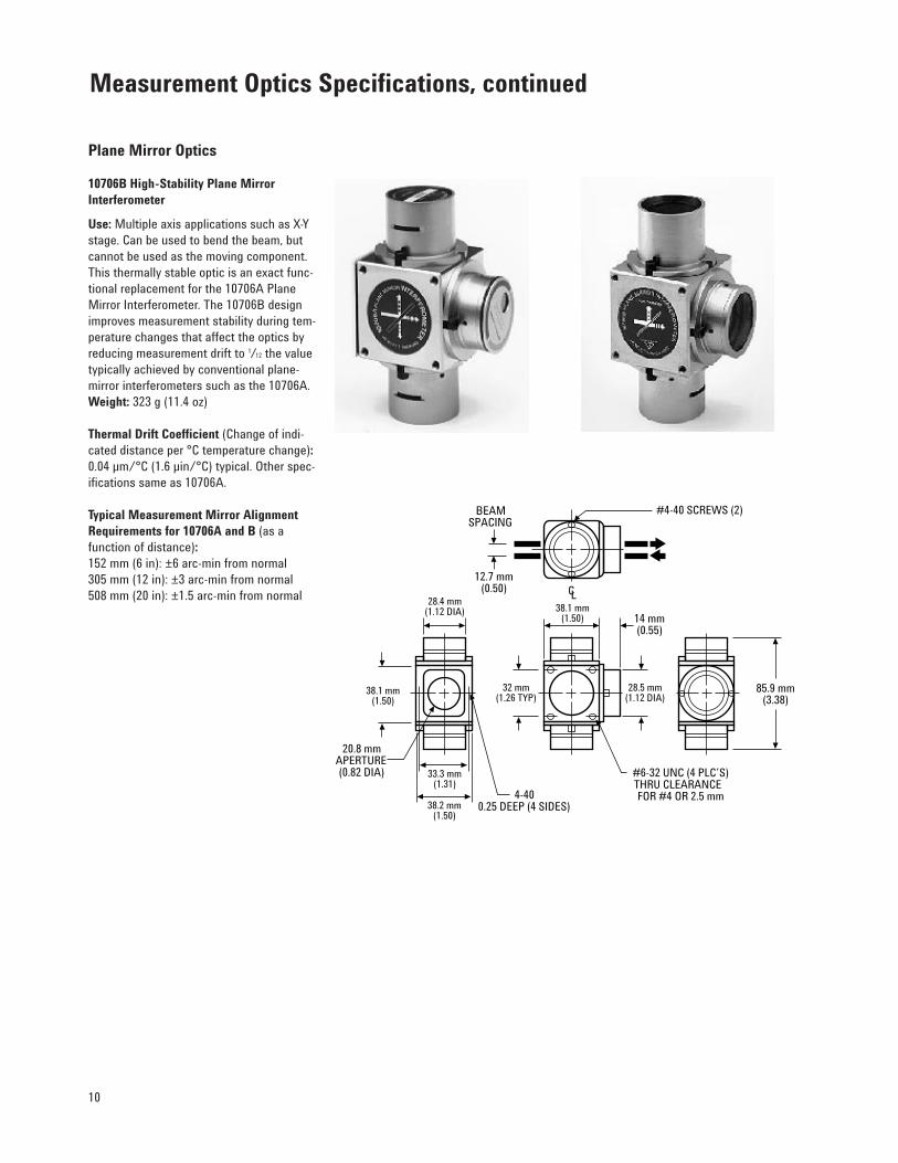
Plane Mirror Optics
10706B High-Stability Plane MirrorInterferometer
Use: Multiple axis applications such as X-Ystage. Can be used to bend the beam, butcannot be used as the moving component.This thermally stable optic is an exact func-tional replacement for the 10706A PlaneMirror Interferometer. The 10706B designimproves measurement stability during tem-perature changes that affect the optics byreducing measurement drift to 1/12 the valuetypically achieved by conventional plane-mirror interferometers such as the 10706A. Weight: 323 g (11.4 oz)
Thermal Drift Coefficient (Change of indi-cated distance per °C temperature change):0.04 µm/°C (1.6 µin/°C) typical. Other spec-ifications same as 10706A.
Typical Measurement Mirror AlignmentRequirements for 10706A and B (as a function of distance):152 mm (6 in): ±6 arc-min from normal 305 mm (12 in): ±3 arc-min from normal 508 mm (20 in): ±1.5 arc-min from normal
Measurement Optics Specifications, continued
CL
#4-40 SCREWS (2)BEAMSPACING
12.7 mm(0.50)
28.4 mm(1.12 DIA)
38.1 mm(1.50)
20.8 mmAPERTURE(0.82 DIA) 33.3 mm
(1.31)4-40
0.25 DEEP (4 SIDES)
28.5 mm(1.12 DIA)
38.1 mm(1.50) 14 mm
(0.55)
#6-32 UNC (4 PLC’S)THRU CLEARANCE FOR #4 OR 2.5 mm
32 mm(1.26 TYP)
38.2 mm(1.50)
85.9 mm(3.38)

11
Interferometer Thermal DriftThis plot shows the measurement driftduring optics temperature changesfor a conventional plane-mirror inter-ferometer compared with the 10706BHigh Stability Plane Mirror Inter-ferometer, the 10715A DifferentialInterferometer, and the 10716A HighResolution Interferometer. The 10706Bis nearly as stable as the more expen-sive 10715A and far more stable thanthe conventional plane-mirror inter-ferometer. The 10716A has the samestability as the 10706B with two timesbetter resolution. For example, with±0.5°C temperature control, measure-ment drift with the 10706B and 10716Ais typically ±0.02 microns (±0.8 µin)compared with ±0.25 microns (±10 µin)with a conventional plane-mirrorinterferometer.
10724A Plane Mirror Reflector
Use: This reflector may be used with the10706A and B, 10715A, and 10716A interfer-ometers for single-axis measurements. Weight: 50 g (1.8 oz) Adjustment Range: ±1° (Alignment hard-ware included)Reflectance: 98% at normal incidence
Recommended Plane Mirror Specifications(for 10706A and B, 10715A, and 10716Areflectors)
Reflectance: 98% at 633 nm at normal incidence Flatness: Flatness deviations will appear as measurement errors when the mirror is scanned perpendicular to the beam.Recommended range is �/4 (0.16 µm or 6 µin) to �/20 (0.03 µm or 1.2 µin) depend-ent on accuracy requirements. Optical Surface Quality: 60–40 per Mil 0-13830
+1.75
+1.50
+1.25
+1.00
+.75
+.50
+.25
+0.00
-.250 2.4 4.8 7.2 12 14.4 16.8 19.2 21.6 249.6
DRIFT AND TEMPERATURE vs. TIME
TIME (Hrs.)
MEA
SUR
EMEN
T D
RIF
T (M
icro
ns)
TEMPER
ATU
RE (ϒC
)
27.00
26.50
26.00
25.50
25.00
24.50
24.00
23.50
23.00
INTERFEROMETER TEMPERATURE
CONVENTIONALPLANE-MIRRORINTERFEROMETER
10715A
10706B & 10716A
INTERFEROMETER TEMPERATURE
MEASUREMENT DRIFT
2X ø 3.556 mm (0.140) THRU
ø 36.068 mm(1.420)
ø 32.766 mm(1.290)
ø 22.860 mm(0.900) APERTURE
3X 2-56 NC-CLASS 3 THRU120ϒ APART
28.388 mm(1.118 DIA)
42.164 mm(1.660 DIA)
3.810 mm(0.150)
20.066 mm(0.790)

12
Differential Interferometer
10715A Differential Interferometer
Use: Performs differential measurementsbetween the supplied reference mirror anda measurement plane mirror. Provides thebest long-term stability of any plane mirrorinterferometer in plane mirror applications.Minimizes deadpath. The Agilent 10715Aeliminates thermal drift in measurementsbecause the entire optical path through theinterferometer is common mode. Alignmentis slightly more complex than the 10706A/B.
For optical layouts requiring the interferom-eter to turn the beam, the 10715A Opt. 001must be used.
Weight:Interferometer: 594 g (1.31 lb)Reference Mirror: 3.2 g (0.1 oz)
Typical Measurement and ReferenceMirror Alignment Requirements (as a function of distance):±2.5 arc-min for 152 mm (6 in) ±1.3 arc-min for 305 mm (12 in) ±0.7 arc-min for 508 mm (20 in)
For complete dimensions see drawing onnext page.
Measurement Optics Specifications, continued
8.1 mm
5.1 mm
EITHER BOTHREFERENCE OR
MEASUREMENTBEAMS
2 X R 3.6 mm
2 X R 3.2 mm
6.3 mm
12.7 mm
EITHER BOTHREFERENCE OR
MEASUREMENTBEAMS
18.3 mm
5.1 mm3.4 mm
9.9 mm
22.9 mm
57ϒ 23'
PART NUMBER: 10715-20205WEIGHT: 3.2 GRAMS
Reference Mirror for Agilent 10715A

13
10716A High Resolution Interferometer
Use: Single and multiple axis high resolu-tion applications such as precision X-Ystages. The Agilent 10716A High ResolutionInterferometer improves the system meas-urement accuracy and repeatability by pro-viding two times better measurement reso-lution along with the same thermal stabilityas the 10706B.
For optical layouts requiring the interferom-eter to turn the beam, the 10716A Opt. 001must be used.
Weight: 502 g (1.11 lb)
Thermal Drift Coefficient (Change of indi-cated distance per °C temperature change):0.04 µm/°C (1.6 µin/°C) typical
Typical Measurement Mirror AlignmentRequirements: Depends on the distance between the interferometer and plane mirror. Typical mirror pitch/yaw angles are:
±6 arc-min for 152 mm (6 in) ±3 arc-min for 305 mm (12 in) ±2 arc-min for 508 mm (20 in)
TO RECEIVER
FROM LASER
90.2 mm*(3.55)
12.7 mm(0.50) SYM @ CL
38.9 mm(1.53)
28.4 mm(1.12)
6-32 UNC(4 PLC’S)
THRUCLEARANCE
FOR #4 OR2.5 mm
32.0 mm(1.26)
32.0 mm(1.26)
8.1 mm(0.32)
85.9 mm(3.38)
12.7 mm(0.50)
TO MIRRORS
28.4 mm(1.12)
14.0 mm(0.55)
38.1 mm(1.50)
12.7 mm(0.50)
23.9 mm(0.94)
A B
*FOR 10715A OPTION 001 and 10716A Option 001 THIS DIMENSION IS 100.1 mm (3.94)
Agilent 10715A and 10716A

14
Multiaxis Optics
Improve Positioning Accuracy for Sub-0.5-micron Lithography and Other ApplicationsAgilent offers three styles of multiaxisinterferometers that make linear andangular measurements. This gives yougreater control of multiaxis stages andallows better overall system accuracy.
Each style is available in two models.These six interferometers provide linear and angular measurements forup to five degrees of stage freedom(X, Y, pitch, roll, and yaw). This givesyou the capability to measure andposition an object with higher preci-sion than linear measurements alone.Finer linewidths in ICs and moreaccurate parts can result from theadditional angular measurement andcontrol available with these interfer-ometers.
The Agilent 10719A and 10721A per-form one- and two-axis differentialmeasurements respectively. Differen-tial measurements provide highlyaccurate position information usingan object such as an optical columnas a position reference. This reducessystem errors in those applications.
The Agilent 10737R, 10737L, 10735A,and 10736A each perform threemeasurements, one linear and twoangular. These three measurementpaths have built-in interaxis align-ment to give high system accuracy.The 10737R and 10737L use a 3-mmlaser beam for a compact optic pack-age. The 10735A and 10736A can use a 9-mm laser beam to provide the widest angle range available.
Increase system accuracy and reduce costs• Maximize system accuracy. Multiaxis
optics provide measurement andcontrol of stage rotations forimproved overlay accuracy.
• Maximize thermal stability. Monolithicoptics and equal glass path lengthsminimize errors due to thermal drift.
• Maximize mechanical stability. Mono-lithic optics provide tight interaxiscoupling and minimize errors dueto vibration.
• Minimize error due to interaxis mis-alignment. Optical design providesguaranteed interaxis parallelism, nolonger dependent on installation.
• Lower installation costs. Referencedoptics, kinematic installation, pre-aligned fiber-optic receiver mounts,and no interaxis adjustments makeinstallation easy.
• Lower manufacturing costs. Multiaxisoptics reduce the number of com-ponents to install.
• Lower service cost. Fiber-opticreceivers are mounted in a con-venient location, and Agilent mul-tiaxis interferometers are easy toremove or install.
Measurement Optics Specifications, continued
Agilent 10719A and 10721A
Agilent 10735A and 10736A Option 001

15
Applications• Lithography• Precision machining• Advanced metrology• R & D on multiaxis stage control• Stage travel characterization• Stage or tool alignment
Multiaxis measurements allow smallerlinewidths, wider fields, and higherthroughputsSmall linewidths and stage motionerrors due to imperfect ways generallyrequire state-of-the-art wafer steppersto control rotational misalignmentabout the Z axis (Yaw). This has typi-cally been done with two discreteinterferometers that require carefulalignment during installation.
Agilent now offers multiaxis interfer-ometers that make linear and rotationalmeasurements in a single compactpackage, conserving valuable space.The interferometers were designedfor excellent built-in parallelism, pro-viding an interaxis alignment superiorto a careful alignment of discreteinterferometers. This helps improvethe grid accuracy needed for smallerlinewidths.
Internal optics are referenced to theirhousings, allowing the interferome-ters to be kinematically located, thenbolted into a precision mount withoutadjustment. Built-in parallelism andreferenced optics save the manufac-ture and service time due to difficultmultiaxis alignments. These featuresalso help achieve better overlay accu-racy than typically possible with dis-crete interferometers.
Pitch and roll measurements enhancewide field optical lithographyTo reduce linewidths, optical lithogra-phy systems such as i-line and deepUV are moving toward larger numeri-cal apertures. The shallower depth offield resulting from a larger numeri-cal aperture can require site-by-sitewafer leveling about the X and Y axis(pitch and roll) to achieve focus overa wide field. Unfortunately, X-Y align-ment accuracy suffers because theAbbé error, neutralized during theglobal alignment, changes duringwafer leveling.
Agilent multiaxis interferometers canmeasure the pitch and roll of the mul-tiaxis stage due to leveling and stagemovement errors, making it possibleto calculate and compensate for thechange in Abbé error. The quick cor-rection saves the time of performing a site-by-site alignment, thus improv-ing throughput.
Mirror mapping improves multiaxis stageperformanceThe yaw of a multiaxis stage is meas-ured using a two- or three-axis inter-ferometer located on either the X or Y axis. When yaw is measured redun-dantly (on both the X and Y axes), thesystem has the additional capabilityof mirror mapping. Mirror mappingallows you to measure and compensatethe flatness deviations in the stagemirrors. This improves total systemaccuracy.
Multiaxis interferometric measurements of stage angles enhance theaccuracy and throughput of fine-line, wide-field lithography systems.
Y A W
RO
L L
P I T C H

16
The 10719A and 10721A allow column-referenced measurementsThe Agilent 10719A and 10721A One-axis and Two-axis DifferentialInterferometers measure the lineardistance between two objects, insteadof the distance between the interfer-ometer and an object. This offers ahigh degree of immunity to unwantedinterferometer displacement such as the thermal expansion between theoptical column and the interferome-ter. Errors common to the referenceand measurement path are removedbecause both are equally affected. Thisimproves overlay accuracy in somelithography systems. The Abbé offseterror is also decreased by using asmall 3-mm beam.
Both interferometers are modularand compact, making it easier to build customized measurement systems with one to six axes.
The 10719A makes either a differen-tial linear or angular measurement.The linear measurement gauges thedisplacement between two objectssuch as an optical column and astage. Alternatively, the 10719A measures either pitch or roll.
The 10721A simultaneously performstwo differential measurements, linearand angular (yaw) displacement. Bothmeasurements reference an externalmirror mounted to an object such asa column.
Column referencing enhances semicon-ductor inspectionMask and IC inspection typicallyrequire the stage to be moved linearlyby small increments with respect toan inspection instrument such as amicroscope. This is required in orderto compare a desired image with thenewly created image. The 10719A wasdesigned to make linear measurementsreferencing an object such as aninspection tool.
X-ray systems benefit from column referencingX-rays provide finer linewidth lithog-raphy because the wavelengths areshorter than optical wavelengths.Slight yaw misalignment reduces thecapability even more in these systemsthan optical lithography systems,because of the finer linewidths. Amethod to achieve the required accu-racy is to reference the multiaxis stagemovement to the mask holder. The10719A and 10721A have been opti-mized to perform these measurements.
Additional features that increase accuracyand decrease cost• Monolithic optics• Guaranteed interaxis parallelism• Prealigned fiber-optic remote
receiver mounting• Referenced optics• Kinematic Installation
Improve overlay accuracy with the Agilent10719A/10721A by referencing the image-making column.
Measurement Optics Specifications, continued
Column
Stage
10719Aor
10721A
MeasurementMirror
ReferenceMirror
Wafer Ref. BeamMeas. Beam

17
10719A One-axis DifferentialInterferometer
Use: Single- and multiple-axis applicationswhere the stage must be linearly positionedwith respect to an external object such as a column or inspection tool. Alternatively,an angle is measured when both referenceand measurement beams measure to thesame mirror.SpecificationsWeight: 300 g (11 oz)Axes: Linear, pitch, or rollAvailable Beam Size: 3 mmThermal Drift Coefficient (Average):
150 nm (5.9 µin) /°CResolution*Linear: 0.6 nmPitch/roll: 0.03 µrad (0.007 arc-sec)Angular Range** (at 300 mm): Pitch/roll: ±0.44 mrad (±1.5 arc-min)Parallelism (Input to output beams):<0.1 mrad (20 arc-sec)
10721A Two-axis DifferentialInterferometer
Use: Multiaxis applications where the stagemust be positioned linearly and angularlywith respect to an external object such as a column or inspection tool.SpecificationsWeight: 300 g (11 oz)Axes: Linear and yawAvailable Beam Size: 3 mmThermal Drift Coefficient (Average):
150 nm (5.9 µin) /°CResolution*Linear: 0.6 nmYaw: 0.05 µrad (0.01 arc-sec)Angular Range** (at 300 mm): Yaw: ±0.44 mrad (±1.5 arc-min)Parallelism (Input to output beams): <0.1 mrad (20 arc-sec)
10719A/10721A InstallationRequirements/Recommendations
Installation and Alignment: Kinematicinstallation requires a referenced surface.See “Laser and Optics Users Manual” for complete installation procedure.Interaxis Alignment: All internal optics are referenced to mounting surface and prealigned.Receivers: Agilent 10780F fiber opticremote receivers. Receiver Alignment: Self aligning whenmounted to interferometer.Measurement and Reference (Plane)Mirror Recommendations: Same as10706A/B; see page 11.
NOTE: Flatness deviations will appear asmeasurement errors when the mirror istranslated across the beam. The mirrormount should not bend the mirror. If accu-racy requirements demand it, mirror flat-ness may be calibrated (scanned and storedin the system controller) to be used as acorrection factor.
10721A
28.98 mm(1.141) 19.05 mm
(0.750)
9.12 mm(0.359)
Output Aperture #1
OutputAperture #2Input
Aperturefor 3 mm
input beam
Fiber Opticsensor head
mounting pins
Four mounting holeson top and bottom
surfaces. (6-32)
57.15 mm(2.250)
9.12 mm(0.359)
7.16 mm(0.282)
3.18 mm(0.125)
9.53 mm(0.375)
12.70 mm(0.500)
19.86 mm(0.782)7.16 mm(0.282)
31.75 mm(1.250)
Ref
Meas
31.75 mm(1.250)
31.75 mm(1.250)
31.75 mm(1.250)
Four beams to reference mirror
Four beams to measurement mirror
12.70 mm (0.500)spacing betweenlinear measurements
19.05 mm(0.750)
60.33 mm(2.375)
38.10 mm(1.500)
Two beams to reference mirror
Two beams to measurement mirror
10719A/10721A
10719A
InputAperturefor 3 mm
input beam
31.75 mm(1.250)
12.70 mm(0.500)
12.70 mm(0.500)
OutputAperture (or Input)
Rear View Front View
10719A 10721A
NOTE:Dimensions givenin millimeters and (inches)
* Resolution is dependent on the electronics used.These specifications are for the 10897B electronics.
** Angular range is the maximum measurement mirrorangle due to all components (i.e., yaw and pitch or yaw and roll) between the measurement mirrorand the interferometer for a 6-axis system. Angularrange is dependent on the measurement distance.Angular range is reduced when the reference mirroris misaligned.

18
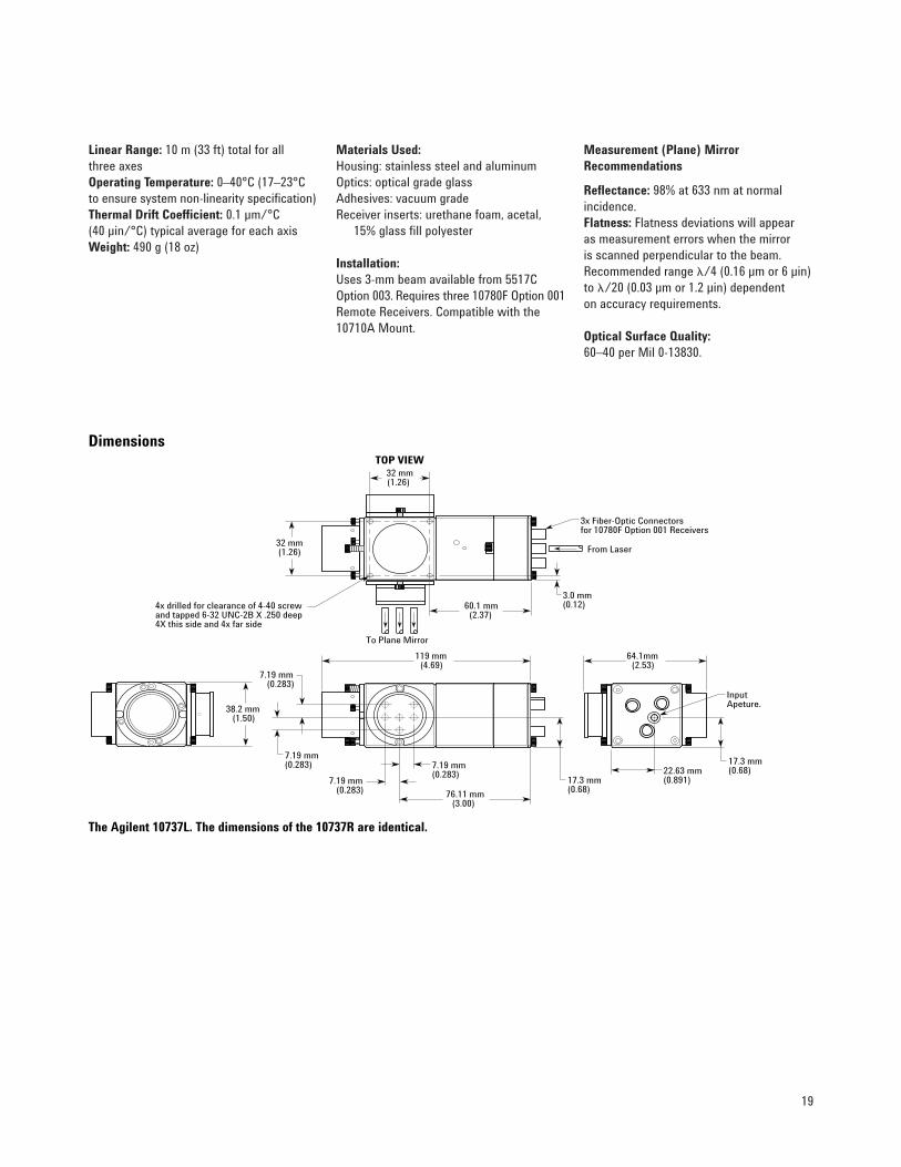
10737L and 10737R Compact Three-AxisInterferometersImprove positioning accuracy of precision equipment with lower-cost, multiaxis laser measurements.Multiaxis measurements improveaccuracy by providing greater controlof multiaxis stages. Each linear andangular degree of freedom can bemeasured and controlled to compen-sate for mechanical imperfections in the stage’s motion. The new Agilent10737L and 10737R Compact Three-axis Interferometers provide thiscapability in a more compact, lower-cost package than the 10735A and10736A Three-axis Interferometers.This allows higher accuracy from multiaxis measurements to be achievedin smaller, lower-cost equipment than was previously possible.
Each 10737L and 10737R makes threelinear measurements. Two angularmeasurements can be calculated fromthis data. Two of these interferome-ters used together provide redundantyaw measurements, which allow mir-ror mapping. Mirror mapping improvesaccuracy by compensating for mirrorflatness deviations.
The 10737L and 10737R also reduceinstallation time and cost. All threeaxes are aligned simultaneously in a process similar to alignment of the10706B High Stability Plane MirrorInterferometer. Both interferometersinclude built-in remote pickups for10780F Option 001 Remote Receivers,which simplifies installation and align-ment. A simple snap connection forthe fiber optic cable quickly connectsthe receiver to the remote pickups.
The 10737L and 10737R differ only in measurement beam direction; the10737L turns the beam to the left andthe 10737R turns the beam to the right.Both interferometers use the 3-mmbeam diameter from the Agilent 5517COption 003 Laser Head.
Improve positioning accuracy with morecompact, lower-cost multiaxis measure-ments with the 10737L and 10737R compactthree-axis interferometers.
Measurement Optics Specifications, continued
Specifications10737L & 10737R Specifications Comparison to 10735A & 10736A
Linear Resolution 5 nm* 5 nm*0.6 nm** 0.6 nm**
Yaw Resolution 0.35 µrad (0.07 arc-sec)* 0.2 µrad (0.04 arc-sec)*0.04 µrad (0.01 arc-sec)** 0.025 µrad (0.005 arc-sec)**
Pitch & Roll Resolution 0.7 µrad (0.14 arc-sec)* 0.24 µrad (0.05 arc-sec)*0.1 µrad (0.02 arc-sec)** 0.03 µrad (0.006 arc-sec)**
Yaw Range††† ±0.44 mrad (±1.5 arc-min) ±1 mrad (±3.4 arc-min)†
±1.5 mrad (±5.1 arc-min)††
Pitch & Roll Range††† ±0.44 mrad (±1.5 arc-min) ±1 mrad (±3.4 arc-min)†
* Using 5527A/B, 10885A, 10895A electronics.** Using 108978 electronics.† Using 6-mm beam diameter.†† Using 9-mm beam diameter.††† At a distance of 300 mm, maximum measurement mirror angle due to all components
(i.e., yaw and pitch or yaw and roll) between the measurement mirror and the interferometer.A six-axis system is assumed.
19
Linear Range: 10 m (33 ft) total for all three axesOperating Temperature: 0–40°C (17–23°Cto ensure system non-linearity specification)Thermal Drift Coefficient: 0.1 µm/°C (40 µin/°C) typical average for each axisWeight: 490 g (18 oz)
Materials Used:Housing: stainless steel and aluminumOptics: optical grade glass Adhesives: vacuum grade Receiver inserts: urethane foam, acetal,
15% glass fill polyester
Installation: Uses 3-mm beam available from 5517COption 003. Requires three 10780F Option 001Remote Receivers. Compatible with the10710A Mount.
Measurement (Plane) MirrorRecommendations
Reflectance: 98% at 633 nm at normal incidence. Flatness: Flatness deviations will appear as measurement errors when the mirror is scanned perpendicular to the beam.Recommended range �/4 (0.16 µm or 6 µin)to �/20 (0.03 µm or 1.2 µin) dependent on accuracy requirements.
Optical Surface Quality:60–40 per Mil 0-13830.
InputApeture.
22.63 mm(0.891)
38.2 mm(1.50)
17.3 mm(0.68)
64.1mm(2.53)
3.0 mm(0.12)
119 mm(4.69)
76.11 mm(3.00)
7.19 mm(0.283)
7.19 mm(0.283)
7.19 mm(0.283)
7.19 mm(0.283)
32 mm(1.26)
32 mm(1.26)
60.1 mm(2.37)
17.3 mm(0.68)
TOP VIEW
From Laser
To Plane Mirror
3x Fiber-Optic Connectorsfor 10780F Option 001 Receivers
4x drilled for clearance of 4-40 screwand tapped 6-32 UNC-2B X .250 deep4X this side and 4x far side
Dimensions
The Agilent 10737L. The dimensions of the 10737R are identical.

20
Additional features that increase accuracyand decrease cost• Wide angle range• Monolithic optics• Guaranteed interaxis parallelism• Prealigned fiber-optic remote
receiver mounting• Referenced optics• Kinematic Installation
The 10735A and 10736A are three-axisoptical benches in single packagesThe 10735A and 10736A Three-axisInterferometers put the functionalityof an optical bench with multiplebeam benders, beam splitters, andthree interferometers in a single high-performance package. This eliminatesexpensive, time-consuming interaxissetup and alignment. The interferom-eters split an incoming laser beaminto three beams to measure lineardistance, pitch, and yaw; or lineardistance, roll, and yaw. Custom Agilentfactory fixtures and measuring equip-ment align and lock the parallelbeams to guaranteed specificationsfor greater stability and accuracythan is practical with discrete compo-nents. This gives you greater overallsystem performance.
Multiaxis installation simplifiedAll axes are referenced to the inter-ferometer’s mounting surface for easykinematic installation onto a user-supplied reference surface. Thismakes installation as easy as slidingthe interferometer into place andbolting it down. The interferometersdiffer in the beam pattern they pro-duce on the measurement mirror,providing flexibility in system design.
Three-axis interferometers provide thehighest angular performance availableThe 10735A and 10736A provide thehighest resolution, widest angularrange, and most accurately alignedthree-axis interferometers availableoff-the-shelf. The high angular resolu-tion gives you greater control overyour multiaxis stage, enabling superiorgrid accuracy in lithography applica-tions. The wide angular measurementrange, with a 9-mm laser beam, allowsboth global and site-by-site stage cor-rection under interferometric control.This helps to achieve high positioningaccuracy without degrading throughput.
Measurement Optics Specifications, continued
The Agilent 10735A and 10736A replace three interferometers and multiple beam bendersand beam splitters with a rigid, high-performance package.

21
10735A/10736A Three-axisInterferometers
Use: Multiaxis applications where linearand angular control of the stage is required.The Agilent 10735A and 10736A providethree linear measurements. Two angularmeasurements can be calculated from thisdata. When an interferometer is placedalong the X axis, yaw (q Z), and pitch (q Y)can be derived in addition to linear (X) dis-placement. When it is placed on the Y axis,yaw (q Z), and roll (q X) can be derived inaddition to linear (Y) displacement. Redundantyaw is useful when mapping measurementmirrors, which provides improved accuracy.The 10735A and 10736A differ in theirmeasurement beam patterns (see drawing).Agilent 10736A Option 001 provides a beambender for fixed compensation axis.
SpecificationsWeight: 5.5 kg (12 lbs)Axes: 3 linear axes which provide linear (X),
pitch, and yaw; or linear (Y), roll, and yaw.Available Beam Diam.: 3/6/9 mmThermal Drift Coefficient (Average):
Axes 1 & 2: 40 nm (1.6 µin) /°CAxis 3: 100 nm (3.9 µin) /°C
Resolution*Linear: 0.6 nmYaw: 0.024 µrad (0.005 arc-sec)Pitch/roll: 0.03 µrad (0.006 arc-sec)Angular Range (at 300 mm displacement)**Pitch/roll: ±1 mrad (±3.4 arc-min) Yaw (for 6-mm beams): ±1 mrad
(±3.4 arc-min) Yaw (for 9-mm beams): ±1.5 mrad
(±5.1 arc-min)Parallelism (Measurement beams): Axes 1 & 2: <40 µrad (8 arc-sec) Axes 1 & 3: <50 µrad (11 arc-sec)
10735A/10736A InstallationRecommendations
Installation and Alignment: Kinematicinstallation procedure requires three refer-enced pins mounted onto a referenced sur-face. See “Laser and Optics Users Manual”for complete installation procedure.Interaxis Alignment: All internal optics are referenced to the mounting surface and prealigned.Receivers: Agilent 10780F Fiber OpticRemote Receivers. Receiver Alignment: Self aligning whenmounted to interferometer.Measurement (Plane) MirrorRecommendations: Same as 10706A/B;see page 11.
* Resolution is dependent on the electronics used.These specifications are for the Agilent 10897B electronics.
** Angular range is the maximum angle between the measurement mirror and the interferometer for a 6-axis system. Angular range is dependent on the measurement distance. Both angles (pitch and yaw or roll and yaw) can be at the angular limit concurrently.
3 Axis Interferometer
10735A
3 Axis Interferometer
10736A
31.25 mm(1.23)
42.5 mm(1.67)
Axis 1 Axis 2 Axis 1 Axis 2
Axis 3
10735A 10736A
10735A
10736A
3X 13.11 mm(0.52)
21.0 mm(0.83)
26.0 mm(1.02)
Measurement Beam Patterns
105.0 mm(4.13)
179.0 mm(7.05)
203.5 mm(8.01)
88.5 mm(3.48)
5.5 mm(0.22)
11.0 mm(0.43)4X Mounting Holes
51.3 mm(2.02)
60.0 mm(2.36)
Input Aperture
Axis 3
NOTE:Dimensions given in millimeters and (inches)

22
Wavelength Tracker
10717A Wavelength Tracker
Use: Tracks changes in the air’s index of refraction to optically compensate forenvironmental changes.Weight: 1.7 kg (3.7 lb)Kinematic Mounting:Angular Adjustment Range (at nominalposition):
Pitch: ±1°Yaw: ±1°
Translation Adjustment Range (at nominalposition):
Vertical: ±3 mm (0.12 in) Horizontal: ±3 mm (0.12 in)
Mounting Hardware Quantity: 3,10-32 UNF2A Screws
Minimum Mounting Clearance Required: 3 mm (0.12 in) around perimeter.
Calibration: Not Required.Interface: Measurement receiver, cable, and appropriate electronics required.
Measurement Optics Specifications, continued
A B
LASER MOUNTING SURFACE
INPUT BEAM FROM LASER
OUTPUT BEAM TO RECEIVER
15.88 mm(0.625)
177.80 ± 0.25 mm(7.000 ± .010)
MOUNTING HOLES3 X 10-32 UNF 2A X 13 (0.5) DP
12.70 m(0.500)
32 mm(1.25)
67 mm(2.63)
CENTERLINE OF LASER BEAM
8.13 mm(0.320) MAX
260.35 mm(10.25)
30.10 ± 0.13 mm(1.185 ± .005)
39.62 mm(1.560)
79.25 mm(3.120)
30.10 ± 0.13 mm(1.185 ± .005)

23
Optics mounts can make alignmentfaster and easier, and are availablefor most optics. Detailed specifica-tions are below.
Optics Mounts
10710A Adjustable Mount
Use: Mount for Agilent 10700A, 10701A,10705A, and 10707A Weight: 88.2 g (3.2 oz) Angular Adjustment Range: Yaw: ±8°Tilt: ±8°
10711A Adjustable Mount
Use: Mount for Agilent 10702A, 10706A/B,10715A, and 10716A Weight: 141.1 g (5 oz) Angular Adjustment: Yaw: ±5°Tilt: ±5 °
10722A Plane Mirror Converter
Use: With an additional 10703A, the 10722Acan be used to convert a 10702A LinearInterferometer into a 10706A Plane MirrorInterferometer. With an additional 10723A,the 10722A can be used to convert a 10702Ainto a 10706B. Weight: 35.5 g (1.3 oz)
10723A High Stability Adapter
Use: If you already use the 10706A, you can easily convert it to a 10706B with the10723A High Stability Adapter. With the10723A you can obtain the much higherthermal stability of the 10706B at nominalcost and effort. Weight: 49 g (1.7 oz)
Accessory Specifications
#4-40 THRU
4 PLC’S
CLEARANCE FOR #4 SCREW (3 mm)
41.66 mm(1.64)
47.0 mm(1.85)
19.6 mm(0.77)
CLEARANCE FOR #4-40 CAP SCREW
OPPOSITE SIDE
19.56 mm(0.77)
12.7 mm DIATHRU(0.50)
YAW
27.9 mm(1.10)
12.7 mm(0.50)
25.4 mm (1.00)
BEAM CENTER LINE
10700A10701A10705A10707A
TILT
32.0 mm(1.26)
59.7 mm(2.35)
64.77 mm(2.55)
32.0 mm(1.26)
CLEARANCE FOR #4-40 CAP SCREW
2 PLC’S
38.1 mm(1.50)
CLEARANCE FOR#4 SCREW
(2.5 mm SCREW)
33.27 mm(1.31)
25.4 mm DIATHRU(1.00)
#4-40THRU
4 PLC’S
YAW
TILT
31.75 mm(1.25) 12.7 mm
(0.50)
25.4 mm(1.00)
12.7 mm(0.50)
BEAM SPACING
10702A10706A/B
10715A10716A
10710A
10711A

24
Two different measurement receiversare available to give you design flexi-bility and maximum system perform-ance. One receiver is required for eachmeasurement axis (including wave-length tracker). The Agilent 10780Caffords the highest sensitivity and low-est cost. The 10780F provides slightlyless sensitivity, but can improve sys-tem performance by enabling you tomount heat-dissipating receiver elec-tronics away from the measurementarea. Hence, higher measurement sta-bility and the resulting accuracy andrepeatability are obtained. The fiber-optic cable used to attach the remotesensor to the receiver electronicsallows design flexibility and easieraccess to the receiver gain adjustment.
Receiver Specifications
Agilent 10780C Receiver
PhotodetectorInsulating
Mounting Pads
Beam Diameter6 mm(0.24)
107.8 mm(4.25)
114.8 mm(4.52)
76.0 mm(3.0)
38.1 mm(1.50)
11.4 mm(0.45)
15.2 mm(0.60)
9.9 mm(0.39)
7.6 mm(0.30)
12.7 mm(0.50)
2.3 mm(0.09 TYP)
Clearance holefor M3 (6-32) Screw
(2 PLC)Use Only Nylon Mounting Screw2360-0369 to Avoid Ground Loop
Beam Spacing
LED
1.8 mm (0.070)Gain Adjustment
54.7 mm(2.15)
24.0 mm (0.945)

25
10780C Receiver and 10780F RemoteReceiver Specifications
Typical Power Requirements:+15 volts at 136 mAMaximum Sensitivity:1.5 µW (10780C)2.2 µW (10780F with 2-m cable)(10780F becomes 5.0 µW with a 10-m
fiber cable.)Heat Dissipation:0.0 W for remote sensor2.0 W typical for receiver
Output Signal:Differential square wave at Doppler-shiftedsplit frequency (100 kHz to 7.2 MHz).Fiber-optic Cable Length (10780F):2 m standard 10 m maximum recommendedAlignment Tolerances:Roll: ±3 degrees Pitch: ±1 degree Yaw: ±1 degree (10780F is self aligning when mounted to the 10715A, 10716A, 10717A, 10719A,10721A, 10735A, and 10736A.)
Weight:136 g (4.8 oz) for 10780C 126 g (4.5 oz) for 10780F 26 g (0.9 oz) for remote sensor with
2-m cable
Agilent 10780F Remote Receiver
114.8 mm(4.52)
7.6 mm(0.30)
76 mm(3.0)
R35 mm Minimum(1.4) Bend Radius
43.1 mm(1.70)
22.4 mm(0.88)
15.5 mm(0.61)
3.5 mm(0.14)
19.1 mm(0.75)
23.8 mm(0.94)
107.8 mm(4.25)
19.1 mm(0.75)38.1 mm
(1.50)
6.0 mm(0.24)
7.6 mm(0.30) 9.9 mm
(0.39)
7.6 mm(0.30)
Clearance hole for M3 (6-32) Screw (2 PLC)
Clearance hole for M3 (6-32) Screw (2 PLC)
BeamDiameter
BeamSpacing
Photodetector
12.7(0.50)
1.8 mm (0.070)
24.0 mm (0.945)54.7 mm
(2.15)
LED

26
Use this configuration guide to design your Agilent laser interferom-eter positioning system. Generallyyou will first refer to the appropriateelectronics data sheet and choose the electronics accordingly. Then
you select your laser head based onsize and axis velocity requirements.Next, sketch your optical configura-tion. From this layout, determineyour optics needs.
Two additional years of return-to-Agilent service are available at purchase for all laser heads and elec-tronics as Option W30. Contact yourlocal Agilent sales representative for details.
0ptics and Laser Head Configuration Guide
Component Needs Comments
Laser Head One required per system5517A Laser Head, lowest velocity, largest size5517B Laser Head, 25% more velocity, small size5517C Laser Head, 75% more velocity, small size
Opt. 003 3-mm beam diameter for use with 10719A and 10721AOpt. 009 9-mm beam diameter
5517D Laser Head, highest velocity, small size5501B Laser Head, lowest velocity, small size, interface same as 5501A
Factory Calibration to MIL-STD 45662 is available at extra cost, and may be specified in the order.
Directing Optics Order as required to manipulate beam path to your configuration10700A 33% Beam Splitter10701A 50% Beam Splitter10707A Beam Bender10567A Dual Beam Splitter—useful in vacuum10725A 9-mm Laser Beam Splitter10726A 9-mm Laser Beam Bender10728A 9-mm Laser Beam Plane Mirror
Measurement Optics 1 interferometer-plus-reflector pair required per axis10702A Linear Interferometer
Opt. 001 Windows—required if interferometer is the moving component10703A Reflector—paired with 10702A10704A Reflector—paired with 10705A10705A Single Beam Interferometer10706B High Stability Plane Mirror Interferometer10713B One-inch bare cube corner10713C 0.5-inch bare cube corner10713D 0.25-inch bare cube corner10715A Differential Interferometer
Opt. 001 Turned Configuration10716A High Resolution Interferometer
Opt. 001 Turned Configuration10724A Plane Mirror Reflector10719A One-axis Differential Interferometer, requires 3-mm beam10721A Two-axis Differential Interferometer, requires 3-mm beam10735A Three-axis Interferometer10736A Three-axis Interferometer
Opt. 001 Adds beam bender10737L Compact Three-axis Interferometer (Left)10737R Compact Three-axis Interferometer (Right)
27
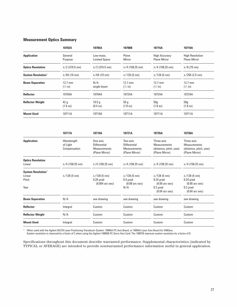
* When used with the Agilent 5527B Laser Positioning Transducer System, 10885A PC Axis Board, or 10895A Laser Axis Board for VMEbus. System resolution is improved by a factor of 2 when using the Agilent 10889B PC Servo Axis Card. The 10897B improves system resolution by a factor of 8.
Specifications throughout this document describe warranted performance. Supplemental characteristics (indicated byTYPICAL or AVERAGE) are intended to provide nonwarranted performance information useful in general application.
Measurement Optics Summary
10702A 10705A 10706B 10715A 10716A
Application General Low-mass, Plane High Accuracy High ResolutionPurpose Limited Space Mirror Plane Mirror Plane Mirror
Optics Resolution �/2 (316.5 nm) �/2 (316.5 nm) �/4 (158.25 nm) �/4 (158.25 nm) �/8 (79 nm)
System Resolution* �/64 (10 nm) �/64 (10 nm) �/128 (5 nm) �/128 (5 nm) �/256 (2.5 nm)
Beam Separation 12.7 mm N/A 12.7 mm 12.7 mm 12.7 mm(1/2 in) single beam (1/2 in) (1/2 in) (1/2 in)
Reflector 10703A 10704A 10724A 10724A 10724A
Reflector Weight 42 g 10.5 g 50 g 50g 50g(1.5 oz) (0.4 oz) (1.8 oz) (1.8 oz) (1.8 oz)
Mount Used 10711A 10710A 10711A 10711A 10711A
10717A 10719A 10721A 10735A 10736A
Application Wavelength One-axis Two-axis Three-axis Three-axisof Light Differential Differential Measurements MeasurementsCompensation Measurements Measurements (distance, pitch, yaw) (distance, pitch, yaw)
(Plane Mirror) (Plane Mirror) (Plane Mirror) (Plane Mirror)
Optics ResolutionLinear �/4 (158.25 nm) �/4 (158.25 nm) �/4 (158.25 nm) �/4 (158.25 nm) �/4 (158.25 nm)
System Resolution*Linear �/128 (5 nm) �/128 (5 nm) �/128 (5 nm) �/128 (5 nm) �/128 (5 nm)Pitch 0.26 µrad 0.4 µrad 0.24 µrad 0.24 µrad
(0.054 arc-sec) (0.08 arc-sec) (0.05 arc-sec) (0.05 arc-sec)Yaw N/A 0.2 µrad 0.2 µrad
(0.04 arc-sec) (0.04 arc-sec)
Beam Separation N/A see drawing see drawing see drawing see drawing
Reflector Integral Custom Custom Custom Custom
Reflector Weight N/A Custom Custom Custom Custom
Mount Used Integral Custom Custom Custom Custom
28
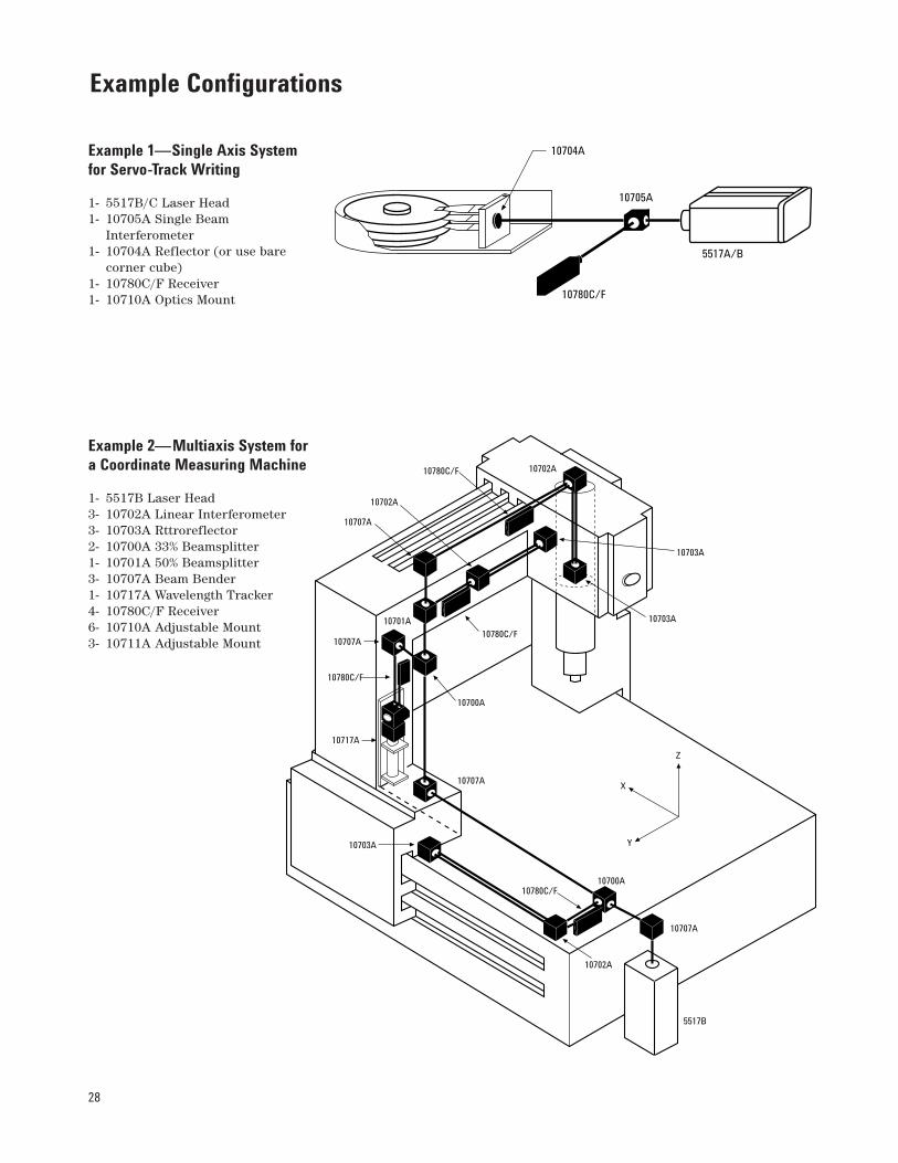
Example 1—Single Axis Systemfor Servo-Track Writing
1- 5517B/C Laser Head1- 10705A Single Beam
Interferometer1- 10704A Reflector (or use bare
corner cube)1- 10780C/F Receiver1- 10710A Optics Mount
Example 2—Multiaxis System fora Coordinate Measuring Machine
1- 5517B Laser Head3- 10702A Linear Interferometer3- 10703A Rttroreflector2- 10700A 33% Beamsplitter1- 10701A 50% Beamsplitter3- 10707A Beam Bender1- 10717A Wavelength Tracker4- 10780C/F Receiver6- 10710A Adjustable Mount3- 10711A Adjustable Mount
Example Configurations
5517A/B
10705A
10780C/F
10704A
10703A
10703A
10702A10780C/F
10702A
10707A
10707A
10701A
10780C/F
10780C/F
10717A
10703A
10707A
10700A
10700A10780C/F
10702A
10707A
5517B
Z
X
Y
29
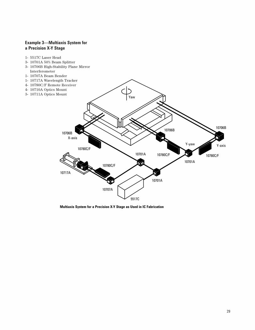
Example 3—Multiaxis System fora Precision X-Y Stage
1- 5517C Laser Head3- 10701A 50% Beam Splitter3- 10706B High-Stability Plane Mirror
Interferometer1- 10707A Beam Bender1- 10717A Wavelength Tracker4- 10780C/F Remote Receiver4- 10710A Optics Mount3- 10711A Optics Mount
10706BX-axis
10780C/F
10717A
10701A
10780C/F
10707A
5517C
10701A
10780C/F
Y-yaw
10701A
Y-axis
10780C/F
10706B10706B
Yaw
Multiaxis System for a Precision X-Y Stage as Used in IC Fabrication

30
Example 4—Three-axis X-Y StageLaser Positioning System withColumn Referencing
1- 5517C Opt. 003 3-mm Laser Head1- 10701A 50% Beam Splitter1- 10707A Beam Splitter1- 10719A One-axis Differential
Interferometer1- 10721A Two-axis Differential
Interferometer3- 10780F Remote Receiver3- 10710A Adjustable Mount
Example 5—Five-axis X-Y StageLaser Positioning System
1- 5517C Opt. 009 9-mm Laser Head1- 10725A 9-mm Laser Beam Splitter2- 10726A 9-mm Laser Beam Bender2- 10736A Three-axis Interferometer6- 10780F Remote Receiver
Example Configurations, continued
5517C Opt. 003
10707A
To 10780FRemote Receiver
MultiaxisStage
10719A
10701A
10707A
To 10780F Remote
Receivers
Column
10721A
5517C Opt. 009
10736A
To Fiber-optic Receivers
MultiaxisStage
10725A
To Fiber-optic Receivers
10726A

Agilent Technologies’ Test and MeasurementSupport, Services, and AssistanceAgilent Technologies aims to maximize the value you receive, while minimizingyour risk and problems. We strive toensure that you get the test and measure-ment capabilities you paid for and obtainthe support you need. Our extensive sup-port resources and services can help youchoose the right Agilent products for yourapplications and apply them successfully.Every instrument and system we sell has a global warranty. Support is available for at least five years beyond the produc-tion life of the product. Two conceptsunderlie Agilent’s overall support policy:“Our Promise” and “Your Advantage.”
Our Promise“Our Promise” means your Agilent testand measurement equipment will meet itsadvertised performance and functionality.When you are choosing new equipment,we will help you with product informa-tion, including realistic performance spec-ifications and practical recommendationsfrom experienced test engineers. When
you use Agilent equipment, we can verifythat it works properly, help with productoperation, and provide basic measurementassistance for the use of specified capabil-ities, at no extra cost upon request. Manyself-help tools are available.
Your Advantage“Your Advantage” means that Agilentoffers a wide range of additional experttest and measurement services, which youcan purchase according to your uniquetechnical and business needs. Solve prob-lems efficiently and gain a competitive edgeby contracting with us for calibration, extra-cost upgrades, out-of-warranty repairs, andon-site education and training, as well as design, system integration, project man-agement, and other professional services.Experienced Agilent engineers and techni-cians worldwide can help you maximizeyour productivity, optimize the return oninvestment of your Agilent instruments andsystems, and obtain dependable measure-ment accuracy for the life of those products.
By internet, phone, or fax, get assistancewith all your test and measurement needs.
Online Assistancewww.agilent.com/find/assistPhone or FaxUnited States:(tel) 1 800 452 4844
Canada:(tel) 1 877 894 4414(fax) (905) 282 6495
Europe:(tel) (31 20) 547 2323(fax) (31 20) 547 2390
Japan:(tel) (81) 426 56 7832(fax) (81) 426 56 7840
Latin America:(tel) (305) 269 7500(fax) (305) 269 7599
Australia:(tel) 1 800 629 485 (fax) (61 3) 9210 5947
New Zealand:(tel) 0 800 738 378 (fax) (64 4) 495 8950
Asia Pacific:(tel) (852) 3197 7777(fax) (852) 2506 9284
Product specifications and descriptions in this document subject to change without notice.
Copyright © 2009 Agilent TechnologiesPrinted in U.S.A. 02/095964-6190E