optical tape measure - iowa state...
TRANSCRIPT

Optical Tape Measure
May04-30
Project Plan
Faculty Advisors: Degang J. ChenAleksandar Dogandzic
Team Members: Nick FreeseBruce FuJason ThompsonEugene Zimmer
Client: Senior Design
May 8, 2023Table of Contents
List of Figures...............................................................................................................................iiiList of Tables.................................................................................................................................ivList of Definitions...........................................................................................................................v
Section 1-Introductory Materials.................................................................................................11.1 Abstract..........................................................................................................................11.2 Acknowledgement..........................................................................................................11.3 Problem Statement........................................................................................................11.4 Operating Environment................................................................................................11.5 Intended Users and Uses...............................................................................................21.6 Assumptions...................................................................................................................21.7 Limitations......................................................................................................................21.8 Expected End Product and Other Deliverables..........................................................2
Section 2-Proposal Approach.......................................................................................................32.1 Functional Requirements..............................................................................................32.2 Constraint Considerations............................................................................................32.3 Technologies Considerations........................................................................................32.4 Technical Approach.......................................................................................................42.5 Testing Requirements....................................................................................................42.6 Security Considerations................................................................................................42.7 Safety Considerations....................................................................................................52.8 Intellectual Property Considerations...........................................................................52.9 Commercialization Considerations..............................................................................52.10 Possible Risks and Risk Management..........................................................................52.11 Project Proposed Milestones and Evaluation Criteria...............................................62.12 Project Tracking Procedures........................................................................................7
Section 3-Statement of Work........................................................................................................7Task 1-Project Definition..........................................................................................................7Task 2-Technology Considerations and Selection..................................................................8Task 3-End-Product Design......................................................................................................9Task 4-End-Product Prototype Implementation....................................................................9Task 5-End-Product Testing...................................................................................................10Task 6-End-Product Documentation.....................................................................................11Task 7-End-Product Demonstration......................................................................................11Task 8-Project Reporting........................................................................................................12
Section 4-Estimated Resources and Schedule...........................................................................134.1 Resource Requirements...............................................................................................13
4.1.1 Personnel Time Requirements............................................................................134.1.2 Other Resource Requirements...........................................................................144.1.3 Financial Requirements......................................................................................14
4.2 Schedules......................................................................................................................15
i
Section 5-Closure Material.........................................................................................................165.1 Project Team Information..........................................................................................16
5.1.1 Client Information...............................................................................................175.1.2 Faculty Advisors Information............................................................................175.1.3 Student Team Information.................................................................................17
5.2 Closing Summary.........................................................................................................18
Section 6-References....................................................................................................................19
ii

List of Figures
Figure 1: First Semester Schedule................................................................................................15Figure 2: Second Semester Schedule............................................................................................16Figure 3: Deliverable Dates..........................................................................................................16
iii

List of Tables
Table 1: Personnel Time Requirements........................................................................................13Table 2: Other Resource Requirements........................................................................................14Table 3: Financial Resources........................................................................................................15
iv
List of Definitions
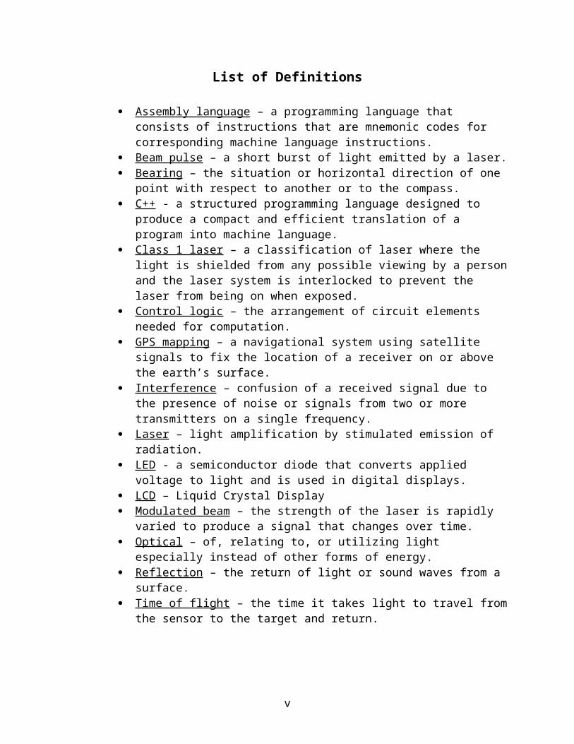
Assembly language – a programming language that consists of instructions that are mnemonic codes for corresponding machine language instructions.
Beam pulse – a short burst of light emitted by a laser. Bearing – the situation or horizontal direction of one point with respect to another
or to the compass. C++ - a structured programming language designed to produce a compact and
efficient translation of a program into machine language. Class 1 laser – a classification of laser where the light is shielded from any
possible viewing by a person and the laser system is interlocked to prevent the laser from being on when exposed.
Control logic – the arrangement of circuit elements needed for computation. GPS mapping – a navigational system using satellite signals to fix the location of
a receiver on or above the earth’s surface. Interference – confusion of a received signal due to the presence of noise or
signals from two or more transmitters on a single frequency. Laser – light amplification by stimulated emission of radiation. LED - a semiconductor diode that converts applied voltage to light and is used in
digital displays. LCD – Liquid Crystal Display Modulated beam – the strength of the laser is rapidly varied to produce a signal
that changes over time. Optical – of, relating to, or utilizing light especially instead of other forms of
energy. Reflection – the return of light or sound waves from a surface. Time of flight – the time it takes light to travel from the sensor to the target and
return.
v

Section 1-Introductory Materials
To begin this project plan, the problem that will be solved over the course of the year needs to be defined. Thus, this section will outline what exactly the problem that the optical tape measure shall solve and what needs to be considered in the design.
1.1 Abstract
Inexpensive ultrasonic tape measures are available that can only measure perpendicular distances to fairly large, flat surfaces. Complex environments make it nearly impossible to determine which surface corresponds to the measured distance. Determining the distance between any two designated spots and producing a model of a measured object are impossible with current ultrasonic tape measures.
The team is designing and implementing an optical tape measure that will measure the distance to any visible spot within its range. The point to which the distance is to be measured will be designated by a laser pointer. Designating an appropriate set of measurements will produce a model of a measured object. Distances up to 100 feet in length will have an accuracy of ± 0.5%.
1.2 Acknowledgement
There are no acknowledgements at this time in the project.
1.3 Problem Statement
Current ultrasonic tape measures are available that will measure perpendicular distances up to fifty feet from the device. Pointing these devices to particular objects can become impossible in complex environments. A tape measure is needed that will measure the distance to any visible spot within its range. The small yet durable device will be able to measure the distance between any two distinct points and create a model with an appropriate set of measurements. This mobile device needs to measure distances up to 100 feet in length with 0.5% tolerance.
An optical tape measure will be designed to solve these problems. A laser will be used to designate the exact point of measurement. The device will run off of small batteries and be able to fit in the palm of the user’s hand. Several measurements can be stored in the device’s memory and transferred to a computer in order to model the measured object. A measurement between two distinct points will be shown on the digital LED display.
1.4 Operating Environment
Wide arrays of operating environments exist for tape measures. The device will be exposed to many possible indoor and outdoor conditions. Precipitation and temperature changes are present in the countless environments where tape measures are used. Windy
1

and dusty conditions should not significantly affect the reliability of the tape measure. The device may also be exposed to physical abuse such as dropping.
1.5 Intended Users and Uses
Several users currently use tape measures. The intended users include high school graduates that regularly use tape measures. A slight tutorial is needed to understand the multiple uses of the optical tape measure. A list of some more specific users may include construction workers, surveyors, golfers, and architects.
The intended uses cover a large variety of applications. Measurements can be taken between any two visible points, including the tape measure itself. Simple models can be created on a computer after storing a set of measurements. Applications may include general measurement, forestry, surveying, utility mapping, GPS mapping, mining, traffic engineering, accident investigation, ship docking, recreational sports, and industry.
1.6 Assumptions
The following is a list of assumptions regarding the design of the product. Updates shall occur as the process continues.
Models will be created on a computer. Users will need a high school level education. Users will know how to use a tape measure. Users will be physically able to use a tape measure. The object points to be measured are stationary. Batteries will provide enough power for the device to operate. All required resources will be available when needed. All team members will be able to contribute enough time to complete the project.
1.7 Limitations
The following is a list of limitations imposed on the design of the product. Updates shall occur as the process continues.
Device must measure up to 100 feet. Accuracy must be within ± 0.5%. Dimensions must not exceed 6”x 8” x 3”. Cost of the prototype must be less than $150. Device must be easily portable. Device shall not weigh over 1 lbs. The weather shall not significantly affect the accuracy of the device.
1.8 Expected End Product and Other Deliverables
The following is a description of the expected end product and the list of provided deliverables.
2

A small, durable, lightweight optical tape measure. This will be the actual device that will obtain and calculate the measurements.
A user’s manual. This will describe to the user how to operate the device. A maintenance manual. This will describe to the user how to properly care for the
device. Test results. These will be the results from the prototype testing.
Section 2-Proposal Approach
In order for the team to be successful with this project they will first need to determine technical, security, intellectual, and safety considerations. The functional requirements of the end-product will also be outlined in this section. Early identification of risks and how they will be handled will also ensure a successful project.
2.1 Functional Requirements
The following list includes the functional requirements specifications. The device will measure distances up to 100 feet. The device will have an accuracy of ± 0.5%. The recorded measurements will be displayed on an LCD screen on the device. Two types of distances can be obtained. The first is the distance from the device
to any point, and the second is the distance between two points in space. Distances between two points in space will be calculated by the device using a
combination of bearings and trigonometry.
2.2 Constraint Considerations
The constraints list describes the restrictions on the end product design. The size of the tape measure will be small enough for the palm of the user’s hand. A couple small batteries need to be able to supply enough power for the device to
operate. The surface of the object being measured needs to reflect the incoming laser
enough for the device to maintain its accuracy. The cost of all the components used in the prototype shall not exceed $150. The lasers used in the device must be of class 1 to ensure that they are not harmful
to the eye. The device should be about as easy to use as a regular tape measure. The device needs to compensate for possible ambient light interference and any
inclement weather conditions. The device must be capable of interfacing with a windows-based computer.
2.3 Technologies Considerations
The technology considerations list describes the available technologies that may be implemented in the final design.
3

C++ and assembly language will be used in programming the LCD and the control logic.
Pulse-type time of flight systems. In this technology the laser emits very brief, very intense pulse of light. The instrument measures the amount of time the pulse takes to reach the target and return, then converts the time into a distance.
Modulated beam systems. The measurement is done by rapidly changing the strength of the laser to produce a signal. The time delay is calculated by comparing the output laser with the delayed signal returning form the target.
Laser beam’s intensity vs. visibility. The visibility of a laser beam at some distance away from the emitter is related to the intensity of the laser beam. The intensity of the laser can be varied until the laser is no longer visible on the object. Comparing this value with a set of known values the distance to the object can be derived.
2.4 Technical Approach
The technical approach of this project will consist of three phases. The first phase will be to research the available optical technologies that can be used in distance measurements. The second phase of the project will be to design and create a prototype that can be tested based on the selected technologies from the first phase. The last phase of the technical approach will be to test the prototype for accuracy, distance, reliability, and durability.
2.5 Testing Requirements
The prototype will be tested and debugged to make sure all parts of the system are being controlled properly. The laser device will initially be tested in low light environments. The device’s measurements will be recorded and checked for accuracy at multiple distances from a known object. Later tests will be done under abnormal environmental conditions. These tests will check the device’s accuracy under several different weather conditions. Accuracy will be recorded for each condition and checked against the accuracy of the ideal test.
The longevity of the device will be checked by submitting the prototype to numerous trials. The prototype will be judged a success if it is still functioning after 1000 trials.
The results of these tests will be checked against the accuracy and distance constraints. If these constraints are met then the design will be judged as a success.
2.6 Security Considerations
Due to the fact that this project is not from a client and is solely for senior design there are no security considerations. Also, many companies currently have optical tape measures on the market so there is currently no competition for the device.
4

2.7 Safety Considerations
The proposed measuring device is a very safe product. The voltages and power the group is working with are very low and do not impose an immediate danger to the developer or to the final user of the product. The use of a laser in the design imposes a possible danger if stared at by the user for prolonged periods.
2.8 Intellectual Property Considerations
The proposed optical tape measure has been created in different forms. The team’s goal is to make sure of uniqueness in the approach. The group also intends to better any of the current similar devices that are in place. In finding a suitable approach for implementation, the team also needs to observe any subcomponents in the design that may be used from previously designed technology and give proper credit to the creator while following their specifications for its use.
2.9 Commercialization Considerations
A tape measure that uses a rolled tape, inside a plastic housing is durable, accurate, and very cheap. One downfall is that it is difficult to make some measurements. These measurements include height of a building, length of a building, or width of a building.
Generally it is difficult to make considerably long measures with a standard tape measure using only one individual. The team needs to be able to make these measurements accurately, quickly, and effectively. The group also has to do it for a reasonable price difference from that of the original tape measure. If the cost of the product is too much higher than that of the standard tape, the market for the product will be lost.
2.10 Possible Risks and Risk Management
Numerous risks arise in the development of the design. Each of the risks involved carry a different amount of weight in regards to importance. The most critical risk analysis is the unforeseen risks. The best possible solution is to identify as many risks as possible to try to prevent the unexpected. Below is a list of identifiable risks in order of importance.
Proper management of the project. With a firm grasp on the task at hand, and a plan of action the project should achieve the desired results. This management includes such items as team members and advisors working together, sticking to the plan of action, and keeping good communication lines. Member attitudes. The success of the project will be highly dependant on the willingness of the members to flex and be open to ideas, be stubborn when necessary, be willing to stand up and be noticed, and be ready to address all problems within the group before it becomes too serious of an issue. Product risks. Risks that may arise with the product range from, not achieving the desired outcome, over or under engineering the device, exceeding cost of the device, a change of a group member or advisor, or other complexities involving the actual design.
5
The first and second risks are the most important because they will effectively sort out the last set of factors for the most part. The client is Senior Design, so the likely hood of losing funding or a client is minimal. If a problem arises, it should be easily resolvable with proper planning and communication between the parties involved. If the parties involved have terminated participation, the remaining parties will divide the missing member’s responsibilities.
2.11 Project Proposed Milestones and Evaluation Criteria
MilestonesThese are the projects major future accomplishments for the project.
Project Definition. This milestone consists of what the team wants to accomplish with the design and how they will go about the designing process.
Technology Considerations and Selection. This milestone will require the team to research all possible technologies that can be used in the design. Once this research is completed, the team will then select which technology will best solve the problems involved in the design.
Process Design. The team will begin designing the prototype using the selected technology from the previous milestone. The result will be the final design of our prototype.
Prototype Implementation. A prototype will be created that will be used in our previously outlined tests.
Testing. The prototype will be tested following the criteria mentioned above in section 2.5. The data will be recorded and evaluated with each test.
Documentation. A user’s manual and maintenance manual will be created that will be delivered with the prototype.
Demonstration. The team will present their successful project to their faculty advisors and the industrial review panel.
Reporting. Three reports will be created throughout the course of the year. The first is the project plan outlining the procedures that will be followed through the year. The second is the design report which will describe the team’s final design of the tape measure. The third will be a final report reflecting on the project as a whole.
Evaluation CriteriaEach of the above milestones will be evaluated on the below scale.
Exceeded-The milestone resulted in a product that went beyond the team’s initial specifications with all members contributing significantly to the milestone.
Met-The milestone resulted in a product that only met the team’s initial specifications and went no further, with most of the team contributing significantly to the milestone.
Almost met-The milestone resulted in a product that accomplished some of the team’s goals but not all of them with half of the team contributing significantly to the milestone.
6

Did not meet-The milestone resulted in a product that did not accomplish any of the team’s goals with little or no teamwork.
Did not attempt-The milestone was never attempted.
2.12 Project Tracking Procedures
Microsoft Project will be used to compare the project progress to that of the previously agreed upon schedule. If the group falls behind schedule it is expected that the group will meet for any additional time necessary to bring the project back on schedule. Microsoft Project will also be used to record personnel time contributions and costs.
Section 3-Statement of Work
This section of the project plan will outline the work that the group will perform over the course of the year. For each task listed below in this statement of work, information pertaining to the objective, the approach, and the expected results of the task will be given.
Task 1-Project DefinitionSubtask 1a-Problem Definition Completion Objective: A complete understanding of the problems that need to be
solved by the implementation of an optical tape measure. Approach: The group will get together to discuss their views on what
needs to be accomplished and then a composite problem statement will be formed. The faculty advisors will also be consulted for their opinions.
Expected Results: It is expected that the group will produce a composite problem statement by the end of this subtask.
Subtask 1b-End-Users and End-Uses Identification Objective: The ideal users and uses of the optical tape measure
need to be determined before the group can proceed with research and design.
Approach: A brainstorming session with all four members of the group will create a list of possible users and uses of the tape measure. This list will then be looked over by the faculty advisors for suggestions.
Expected Results: A list of possible users and uses to consider in the design will result from this subtask.
Subtask 1c-Constraint Identification Objective: Many constraints need to be taken into account in order
to create a successful design. Identifying all of these constraints will allow the design process to proceed smoothly.
Approach: Another brainstorming session among the four group members will take place. The results of this session will then be checked over by our faculty advisors for any discrepancies.
7

Expected Results: This brainstorming session will also result in the production of a list of possible constraints to consider.
Task 2-Technology Considerations and SelectionSubtask 2a-Identification of Possible Technologies Objective: The group needs to decide on what is the best method
to use in the design of the tape measure. Identification of all the options available is needed to be sure that this is accomplished.
Approach: The faculty advisors will be consulted for their opinions on what technologies could be used. The group will then add any other possible technologies it can discover.
Expected Results: The result of this research will be list of viable technologies that can be used to create an optical tape measure.
Subtask 2b-Identification of Selection Criteria Objective: The list of available technologies will need to be
evaluated based on what is felt to be the best criteria. This criteria needs to be created in this subtask.
Approach: The group will meet to decide how they feel they can best judge a technology.
Expected Results: The selection criteria will be produced during this subtask. These criteria are expected to be able to determine the best and simplest solution to the technology concerns.
Subtask 2c-Technology Research Objective: The criteria from subtask 2b will be used to evaluate
the technologies, but it is necessary to understand each technology properly in order to properly evaluate it. Research will thus be done to attempt to understand each of the technologies in the group’s list.
Approach: Resources such as the internet, library, university faculty, and anything else available to the group will be used to obtain as much information on each technology as possible.
Expected Results: A complete understanding of all the available technologies by each member of the group should result from the research done during this subtask.
Subtask 2d-Technology Selection Objective: With this subtask, the time for designing the tape
measure is almost near. Thus, the best technology to use in the design should be picked out of the list created in subtask 2a.
Approach: Using the research from subtask 2c and the criteria from subtask 2b, each technology will be evaluated and ranked with respect to all the other technologies.
Expected Results: The best technology to implement in the group’s design for the tape measure is expected to result from this selection process.
8
Task 3-End-Product DesignSubtask 3a-Identification of Design Requirements Objective: The decision of what the tape measure should do and
what it should not do now needs to be determined. Approach: Most of the list that will be created will be determined
by what the project description gives the group. Once these guidelines are established, smaller details will then be identified by the group in collaboration with the faculty advisors.
Expected Results: A list of design specifications is expected to result from this subtask.
Subtask 3b-Design Process Objective: The end-product now needs to be designed. The design
needs to meet the requirements in subtask 3a, as well as the other requirements determined earlier such as users and uses, environment, and constraints.
Approach: The group will already have formed a general idea of what it wants to do earlier in the research parts of the project. These ideas will then be used to create rough sketches and drafts of the end-product. The final design will then be created using computer software available from the university.
Expected Results: The first draft of the optical tape measure should be produced by the end of this subtask.
Subtask 3c-Documentation of Design Objective: A record of what was done in the design will need to be
kept in order to later be used to determine how to make the design better if testing fails to meet expectations. A record will also need to be kept to inform others of what the design for the tape measure is so that they might be able to reproduce the tape measure and the testing results.
Approach: The group members will each keep a log of what they did on the project. At the end of the design, these logs will be drawn from in creating a document that lays out the design process. Another document will also be created called the design report which will also outline what was done in the design phase of the project.
Expected Results: A design report and a group project log will result from the collaboration of the individual log books.
Task 4-End-Product Prototype ImplementationSubtask 4a-Identification of Prototype Limitations and Substitutions Objective: Problems may arise in the implementation of an optical
tape measure prototype. These limitations need to be identified in order to decide upon acceptable substitutions that can be made to get around these limitations.
Approach: The group will research the implementation techniques available and then evaluate what each techniques advantages and disadvantages are.
9

Expected Results: Solutions to any implementation problems will result from this subtask.
Subtask 4b-Implementation of Prototype End-Product Objective: A prototype needs to be implemented using the
techniques determined in subtask 4a. Approach: The agreed upon technique from subtask 4a will be
used in the implementation of the prototype. Expected Results: A prototype of the design is expected to be
created in this subtask.
Task 5-End-Product TestingSubtask 5a-Test Planning Objective: The group needs to decide upon what types of tests
they want to perform and what criteria they want the prototype to meet for each test.
Approach: Research by each member in the group will be done. The resulting information will then be discussed at the weekly team meeting.
Expected Results: The purpose of this discussion will be to create a list of tests and test criteria that can then be used to test the prototype.
Subtask 5b-Test Development Objective: How to go about the actual testing of the prototype
using the tests determined in subtask 5a now needs to be decided. Approach: Based on the research from subtask 5a the group will
attempt to find all of the resources needed in order to perform each desired test. The faculty advisors and other faculty may be consulted about these resources availability. Procedures for each test will also be drawn up so that test results can be duplicated.
Expected Results: Procedures and available proper test environments are expected to result from this subtask.
Subtask 5c-Test Execution Objective: The group needs to determine how well their design
will perform. To do this, data needs to be collected using predetermined tests that will later be evaluated.
Approach: The group will perform each of the decided upon tests using the previously created procedures.
Expected Results: A good amount of data on the performance of the prototype is expected to result from the many rounds of testing.
Subtask 2d-Test Evaluation Objective: This subtask determines whether the group succeeded
in its initial design or failed. If the tests failed the group can then try to amend their design in order to succeed.
Approach: The data collected from the rounds of testing will be compared to the criteria decided on in subtask 5a to see if the prototype met or didn’t meet these criteria.
10

Expected Results: A complete evaluation of the successes and failures of the prototype will be produced in this subtask.
Subtask 5e-Documentation of Testing Objective: In order to ensure that others can obtain the same
results with their own testing. This way it can be verified that the prototype works or does not work.
Approach: Each group member will keep a record of their own participation in the testing procedure in their log book. The log books will then be collaborated into a step by step document outlining everything done in the testing.
Expected Results: A document that outlines each task performed during the testing procedure is expected.
Task 6-End-Product DocumentationSubtask 6a-Development of End-User Documentation Objective: The end-users of the optical tape measure need
instructions on how to use the end-product. Approach: A word processing program will be used to write a
document that outlines how to get the end-product to work properly. This document will be written with the mindset that the reader has no technical background and no idea how to work the device.
Expected Results: A user’s manual will be produced in this subtask.
Subtask 6b-Development of Maintenance and Support Documentation Objective: How to maintain the tape measure needs to be recorded
for anyone who may need this information. Approach: A word processing program will be used to write a
document that describes what needs to be considered for the maintenance and care of the end-product. This document should be written for an audience with a little more technical expertise.
Expected Results: A maintenance manual that provides all maintenance information for the tape measure.
Task 7-End-Product DemonstrationSubtask 7a-Demonstration Planning Objective: The design team will need to present all the work that
they have done in regards to their project to a variety of audiences. Approach: The group will meet and create a power point
presentation following the criteria given in the Senior Design Course Notes.
Expected Results: A power point presentation that describes the course of the work done on the optical tape measure is expected to be created in this subtask.
Subtask 7b-Faculty Advisors Demonstration
11

Objective: This will serve as a test demonstration to prepare the group for their final demonstration to the Industrial Review Panel.
Approach: The presentation prepared in subtask 7a will be given to the faculty advisors. The advisors are then expected to evaluate the presentation using the criteria from the Senior Design Course Notes.
Expected Results: The result of this subtask will be constructive criticism that can be used to improve the group’s presentation.
Subtask 7c-Industrial Review Panel Demonstration Objective: This presentation will give the group experience in
what it is like to present to a group of professionals. Approach: The group will give their revised demonstration to the
panel. Expected Results: The only results expected from this subtask are
experience and a grade for EE 492.
Task 8-Project ReportingSubtask 8a-Project Plan Development Objective: An outline for the year needs to be created that will
guide the group through the course of the senior design process. Approach: The group will meet and divide the work load amongst
them. Each member will then do their own section and then all of the sections will be combined into a final document that can then be edited.
Expected Results: The product of this subtask will be a document that the group and others can refer to in order to see what the group is planning.
Subtask 8b-Project Poster Development Objective: A poster needs to be created for EE 491 that will
convey as much information to the audience as possible in as short a period of time as possible.
Approach: The group will meet and develop ideas on what needs to be put on the poster and how to best present that needed information.
Expected Results: A large poster is expected that can be displayed anywhere and convey a lot of information about the group optical tape measure.
Subtask 8c-End-Product Design Report Development Objective: As discussed earlier, the design of the tape measure
needs to be documented in extreme detail. This will be the main document that will accomplish this.
Approach: A word processing program will be used to create a document that includes all of the design steps and all of the work done by each individual in the group.
Expected Results: A document that can be read by other groups who can then reproduce the design with little difficulty will result from this step.
12

Subtask 8d-Project Final Report Development Objective: At the end of the project a document needs to be
created that will serve as a record for everything that was done during the entire project.
Approach: A word processing program will be used to create a document that will contain all information regarding the project and the work done on the project.
Expected Results: From this subtask a report is expected that will provide the reader with all the information regarding the optical tape measure project.
Subtask 8e-Weekly Email Reporting Objective: The weekly emails will provide each member in the
group and the faculty advisors and the course instructor with current information regarding the project and its current situation.
Approach: On Sunday nights the group will give the communication coordinator information regarding what each group member did that week. The coordinator will then combine this data into an email which will be sent to [email protected] by each Monday at noon.
Expected Results: The weekly emails will result with a constant knowledge of where the project is at and who worked on what each week. This way there will be no confusion.
Section 4-Estimated Resources and Schedule
Throughout the course of the optical tape measure project, the group will be required to use many resources to perform certain tasks. Time commitment, financial needs, schedules, and other miscellaneous information needs to be determined before the team begins their project in order to prevent any major oversights that can be parasitic to the project later in the design process. The following two subsections will contain the estimated information regarding the above mentioned concerns.
4.1 Resource Requirements
The resources required for this project can be divided into three subsections. These subsections are contained below. The first is the personnel time requirements, the second is other resources, and the final subsection is financial requirements.
4.1.1 Personnel Time RequirementsThe estimated amount of time that each group member felt they would be able to spend on each task during the optical tape measure project is available in Table 1 below.
13
Table 1: Personnel Time Requirements
Personnel Time Requirements
Name Definition/Research
Product Design
Prototype Implementing
Product Testing
Documentation Total
Nick Freese 22 35 20 18 12 107Jason Thompson 16 34 21 21 13 105BruceFu 23 37 17 16 10 103Eugene Zimmer 19 35 18 20 10 102
Totals 80 141 76 75 45 417
4.1.2 Other Resource RequirementsThere are many other resources besides time that the group may require throughout the course of the year. These resources may be in the form of materials, facilities, and software. The group has created a list of all these other possible resources and included them in Table 2Table 2. It is important to note that the data in this table are just estimates since the actual design of the tape measure has not been determined.
Table 2: Other Resource Requirements
Other Resource Requirements
Item Team Hours Other Hours CostProject Poster 10 0 $50.00Document Printing 10 0 DonatedDesign Implementation 72 Unavailable $150.00Computer Software 30 0 DonatedTotals 122 Unavailable $200.00
4.1.3 Financial RequirementsIt is necessary for the team to determine how much their project may cost so that they will not run over budget. The estimates for the cost of the project are included below along with the estimated cost of labor in Table 3.
14

Once again it is important to note that because the final design not yet known the average senior design amount of $150 is allotted to the design implementation. This amount may be lower than this but the team has set this cost as its upper limit.
Table 3: Financial Resources
Financial Resources
Item Without Labor With LaborProject Poster $50.00 $50.00Document Printing Donated DonatedDesign Implementation $150.00 $150.00Labor at $10.50 per hour Freese, Nick $1123.50 Zimmer, Eugene $1123.50 Thompson, Jason $1123.50 Fu, Bruce $1123.50
Subtotal $4494.00Total $200.00 $4694.00
4.2 Schedules
Due to the complexity of the design process it is essential that the team outline its projected schedule well before the main bulk of the work is to be done. This way the group will have a complete understanding of everything that needs to be done and thus does not procrastinate and end up with an incomplete project. In the following three Gant charts the projected schedules and main deliverable dates are shown. In Figure 1 the schedule for the first semester of senior design is presented. In Figure 2 the second semester schedule is presented. Presented in Figure 3 are the deliverable dates. These charts were created using Microsoft Project.
15

Figure 1: First Semester Schedule
Figure 2: Second Semester Schedule
16
Figure 3: Deliverable Dates
Section 5-Closure Material
This section will summarize everything that was contained in this project plan along with all contact information for the faculty advisors and the team members.
5.1 Project Team Information
Listed below is the contact information that may be needed during the project. The first subsection contains the data for the project client, the second subsection contains the data for the two faculty advisors, and the third subsection contains the data for the student team members.
5.1.1 Client InformationThe client for this project will be the Iowa State University Senior Design program. The two contacts listed below are the individuals in charge of this program.
Professor John W. Lamont324 Town EngineeringAmes, IA 50011Phone Number: (515) 294-3600Fax Number: (515) 294-6760Email Address: [email protected]
Professor Ralph E. Patterson, III326 Town EngineeringAmes, IA 50011Phone Number: (515) 294-2428Fax Number: (515) 294-6760Email Address: [email protected]
5.1.2 Faculty Advisors InformationDegang Chen
17

329 DurhamAmes, IA 50011Phone Number: (515) 294-6277Fax Number: (515) 294-8432Email Address: [email protected]
Aleksandar Dogandzic3119 CooverAmes, IA 50011Phone Number: (515) 294-0500Fax Number: (515) 294-8432Email Address: [email protected]
5.1.3 Student Team InformationJason Thompson905 Dickinson #112Ames, IA 50014Phone Number: (515) 292-0195Email Address: [email protected]
Eugene Zimmer3021 Regency CT #78Ames, IA 50010Email Address: [email protected]
Bruce Fu4529 Webster STAmes, IA 50014Phone Number: (515) 441-0620Email Address: [email protected]
Nick Freese1007 Lincoln Way #6Ames, IA 50010Phone Number: (319) 929-1300Email Address: [email protected]
5.2 Closing Summary
As the world advances and technologies become smaller and faster the old way of accomplishing simple tasks has become obsolete. Not that long ago everyone used the regular tape measure to which we are all accustomed. Now, however, there are several more options available to someone wanting to make a measurement. Ultrasonic devices have been created that have enabled a user to simply push a button to obtain a distance measurement to a desired object, but even these devices have their drawbacks.
18

Ultrasonic tape measures are difficult to aim and are only accurate up to 50 feet. Thus this project will attempt to amend these difficulties by creating an optical device capable of measure distances up to 100 feet with the same type of accuracy that the ultrasonic devices have at 50 feet. The creation of an optical tape measure will also allow for the designation of the aiming point, thus making this measurement option a lot faster and a more reliable way of obtaining measurements.
19
Section 6-References
Laser Optronix. http://www.laseroptronix.com
Standard Classifications for Lasers. http://www.epanorama.net/documents/lights/laserclass.html
Senior Design Homepage. http://seniord.ee.iastate.edu/
Merriam Webster Online. http://www.m-w.com/home.htm
Acuity Laser Measurement. http://www.acuityresearch.com
The Optical Tape Measure by American Visionwear. http://www.opticaltapemeasure.com
Laser Technology Inc. http://www.lasertech.com/
20