optical switch user manual - teleste · optical switch user manual, 59300281, rev002 user manual...
TRANSCRIPT

Optical switch user manual, 59300281, rev002
User manual
Optical switch 1x2 for singlemode fibre
An essential part of complete CFO Fibre Optic Platform are the COM series accessories. Among several different COM models the optical switches offer an easy way to provide a redundant
fibre optic operation.
For CFO series (CEV/x61/x91)

Optical switch user manual rev002
Contents
Optical switch introduction ..................................................................................................................................... 1General .............................................................................................................................................................. 1Fibre connection................................................................................................................................................. 1Frame installation ............................................................................................................................................... 1Stand-alone installation ...................................................................................................................................... 2
Operation ................................................................................................................................................................... 3Link Source Alarm (LSA) .................................................................................................................................... 3LSA commands .................................................................................................................................................. 3Switch port positions and indicator leds ............................................................................................................. 3
Settings ...................................................................................................................................................................... 4Wiring example .................................................................................................................................................. 4DIP switch settings ............................................................................................................................................. 4LSA switching logic ............................................................................................................................................ 5
Application example ................................................................................................................................................. 6
Technical specifications........................................................................................................................................... 7
Legal declarations .................................................................................................................................................. 10
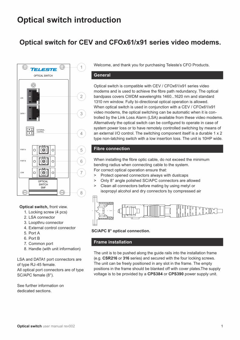
Welcome, and thank you for purchasing Teleste’s CFO Products.
General
Optical switch is compatible with CEV / CFOx61/x91 series video modems and is used to achieve the fibre path redundancy. The optical bandpass covers CWDM wavelenghts 1460...1620 nm and standard 1310 nm window. Fully bi-directional optical operation is allowed. When optical switch is used in conjunction with a CEV / CFOx61/x91 video modems, the optical switching can be automatic when it is con-trolled by the Link Loss Alarm (LSA) available from these video modems. Alternatively the optical switch can be configured to operate in case of system power loss or to have remotely controlled switching by means of an external I/O control. The switching component itself is a durable 1 x 2 type non-latching switch with a low insertion loss. The unit is 10HP wide.
Fibre connection
When installing the fibre optic cable, do not exceed the minimum bending radius when connecting cable to the system.For correct optical operation ensure that: > Protect opened connectors always with dustcaps > Only 8° angle polished SC/APC connectors are allowed> Clean all connectors before mating by using metyl or isopropyl alcohol and dry connectors by compressed air
Optical switch for CEV and CFOx61/x91 series video modems.
Optical switch introduction
OPTICAL SWITCH
DATA 1
PORT A
PORT B
EXTERNALCONTROL
OPTICAL SWITCH
SMF
LSA
COM
1
2
3
4
5
6
7
8
Optical switch, front view. 1. Locking screw (4 pcs)2. LSA connector3. Loopthru connector4. External control connector5. Port A6. Port B7. Common port8. Handle (with unit information)
LSA and DATA1 port connectors are of type RJ-45 female.All optical port connectors are of type SC/APC female (8°).
See further information on dedicated sections.
SC/APC 8° optical connection.
Frame installation
The unit is to be pushed along the guide rails into the installation frame (e.g. CSR216 or 316 series) and secured with the four locking screws. The unit can be freely positioned in any slot in the frame. The empty positions in the frame should be blanked off with cover plates.The supply voltage is to be provided by a CPS384 or CPS390 power supply unit.
Optical switch user manual rev002 1

Stand-alone installation
The units can be installed for stand-alone use by using a CMA025 (installation for 10HP wide CFO series units) module adapters. To insert a CFO card unit into the module adapter, push the unit along the guide rails into module until the unit is firmly attached. Secure the plug-in unit with the upper and lower locking screws.. The stand-alone unit should be mounted to a vertical surface.
The 12V DC supply voltage is supplied by the means of a separate mains adapter with a regulated output, (e.g. CPS251). Please refer to separate documention for module adapters and mains adapters.
By using an optional mounting kit (item code CIK002) a rear side mounting is enabled (below CIK002 rear mounting kit dimensions).
Power supply connection.
CPS251 12VDC Mains adapter.
CMA025 module adapter.
141.5
CMA
Wall
220
119.5
61.5
43
33.5
58
13
5.2
Ø10.5
Ø5.2
30
14
10
.5
18
.5
For limited space installation the CMA module adapters can be rear-mounted by means of an optional installation kit CIK002. CMA025 module adapter with CIK002 rear mounting kit.
2 Optical switch user manual rev002

Operation
Link Source Alarm (LSA)
CEV / CFOx61/x91 series video modem’s (transmitter and receiver) contact closure output can be used to control optical switch when the video modem’s LSA (Link Source Alarm) mode is enabled. When operating with LSA, a connection cable is required between the optical switch and video modem.
Note! Enabling LSA (LSA ON) overrides all other functions of video modem’s CC output.
When LSA is enabled, video modem’s contact closure input and data 1 connections are normally available via optical switch’s DATA 1 (loopthru) connector when using a connection cable between CEV / CFOx61/x91 series video modem and optical switch. The recommended connection cable is Teleste CIC702 (RJ-45/RJ-45).
LSA commands
CEV / CFO16x/19x series video modem includes a command line interface (CLI) for configuration purposes. With help of CLI commands you can configure the LSA settings. See CEV / CFO16x/19x series video modem’s user manual for more details how to use the CLI.
: Enables/disables LSA monitoring on the device: Displays or sets the link source alarm switching delay (in seconds).
Delay defines how long the device will wait for the optic link to get up before operating the switch for the first time
: Displays or set the link source alarm hold time (in seconds). Holdtime defines the waiting time to ensure the recovery of the optical link
: Resets device source alarm to it’s initial state (see page 5 for switch-ing logic flow chart)
Switch port positions and indicator leds
When the switch is not activated (initial state), the com port is connected to port A, and all front panel RJ-45 connectors leds (1-4) are dark.
When the switch is activated (alarm state), the com port is connected to port B and all front panel RJ-45 connectors leds (1-4) are green.
The switching can be controlled by the following ways:• LSA (contact closure output at video modem)• System power fail (rack power supply)• External control open (pins open)• External control closed (pins closed)• Remote controlled via video modem link (normal contact closure operation, see note on the right)
Note! When using LSA control, the optican switch operates automatically with the logic descripted in page 5.
Port B
Port ACom
LSA on / offLSA delay
LSA holdtime
LSA reset
COM port positions.
The optical switch’s initial state is always port position A, except when using system power switching mode, at that control mode the switch’s initial state is position B.
Optical switch user manual rev002 3

OPTICAL SWITCH
MODULE
LINK
VIDEO 1
VIDEO 2
VIDEO 3
VIDEO 4
AUDI
OM
GM
TDA
TADA
TA /
CCL
STATUS
ETHE
RNET
BRI
DGE
OPTICAL TRANSMITTER
DATA 1
PORT A
PORT B
Loopthru
Video modem’sdata 1 & CC
(see video modem user manual for pin configuration)
Control Cableto link LSA alarm(direct connected
e.g. CIC702)
Port A
Port BFibre
patch cable(e.g. OPA112)
EXTERNALCONTROL
OPTICAL SWITCH
SMF
LSA
COM
Settings
Wiring example
When the connection cable is connected between video modem and optical switch, the video modem’s DATA 1 and contact closure connections are available via the optical switch’s DATA 1 (loopthru) connector.
Wiring example with four channel video transmitter.
DIP switch settings
There are several ways to control optical switch. The desired control mode can be selected by the means of DIP switches (see settings below). The default factory setting is LSA controlled.
1ON 2 3 4 5 6
DIP swithes are located on the bottom of unit.
Note! When the optical switch is configured to LSA mode, there is an alternative possibility to control the switch remotely. At the video modem configuration session (CLI) the LSA function can be disabled and the contact closure channel is returned back to normal CC usage. This enables a possibility to control the CC channel from the remote end of the fibre link and therefore to control the optical switch operation as well.
DIP switch
LSA con-trolled
EXTmode A
EXTmode B
System power
1 OFF ON OFF OFF
2 ON OFF OFF OFF
3 OFF OFF OFF OFF
4 OFF OFF OFF OFF
5 OFF OFF ON ON
6 OFF OFF ON OFF
Switchposi-tion
LSA activeCOM -> port B
EXT closedCOM -> port B
EXT closedCOM -> port A
Power ONCOM -> port B
LSA inactiveCOM -> port A
EXT openCOM -> port A
EXT openCOM -> port B
Power OFFCOM -> port A
4 Optical switch user manual rev002

LSA switching logic
Link fails
LSA delay time
Link gets up
Link doesn'tget up
Initialstate
Normal state(Switch position: Com - port A)
User definable time(Waiting time in seconds before the switch operates after first detected Link Loss Alarm)
LSA control activated(Switch position: Com - port B)
LSA control is activated(Switch position: Com - port B)
Link gets upLSA control is kept activated(Switch position: Com - port B)
LSA control is kept de activated(Switch position: Com - port A)
LSA hold timeUser definable time(Waiting time in seconds to ensure that optical connection has been established successfully)
User definable time(Waiting time in seconds to ensure that optical connection has been established successfully)
Link doesn'tget up
LSA control is de-activated(Switch position: Com - port A)
Link gets up
LSA hold time
Link doesn'tget up
To return the switch back to the initial state, use CLI with a command lsareset to reset the LSA.
Optical switch user manual rev002 5
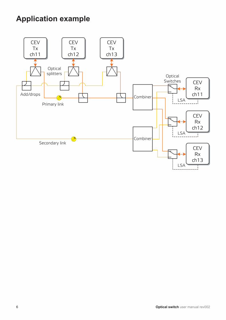
Opticalsplitters
Primary link
Secondary link
Add/dropsCombiner
OpticalSwitches
LSA
LSA
LSA
Combiner
CEVTx
ch11
CEVTx
ch12
CEVTx
ch13
CEVRx
ch11
CEVRx
ch12
CEVRx
ch13
Application example
6 Optical switch user manual rev002
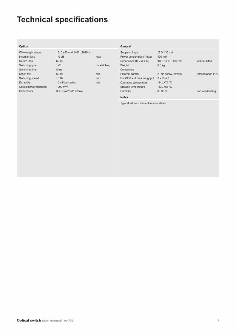
General
Supply voltage 12 V / 30 mAPower consumption (max) 400 mWDimensions (H x W x D) 3U • 10HP • 190 mm without CMAWeight 0.5 kgConnectorsExternal control 2 -pin screw terminal (closed/open I/O)For CEV and data troughput 2 x RJ-45Operating temperature -34...+74 °CStorage temperature -40...+85 °CHumidity 0...95 % non condensing
Notes
Typical values unless otherwise stated
Optical
Wavelenght range 1310 ±50 and 1460...1620 nmInsertion loss 1.0 dB maxReturn loss 60 dBSwitching type 1x2 non-latchingSwitching time 8 ms Cross-talk 60 dB minSwitching speed 10 Hz maxDurability 10 million cycles minOptical power handling 1000 mWConnectors 3 x SC/APC 8° female
Technical specifications
Optical switch user manual rev002 7

Notes
8 Optical switch user manual rev002

Notes
Optical switch user manual rev002 9

Legal declarations
Copyright © 2012 Teleste Corporation. All rights reserved.
TELESTE is a registered trademark of Teleste Corporation. Other product and service marks are property of their respective owners.
This document is protected by copyright laws. Unauthorized distribution or reproduction of this document is strictly prohibited.
Teleste reserves the right to make changes to any of the products described in this document without notice and all specifications are subject to change without notice. Current product specifications are stated in the latest versions of detailed
product specifications.
To the maximum extent permitted by applicable law, under no circumstances shall Teleste be responsible for any loss of data or income or any special, incidental,
consequential or indirect damages howsoever caused.
The contents of this document are provided “as is”. Except as required by applicable law, no warranties of any kind, either express or implied, including, but not limited to, the implied warranties of merchantability and fitness for a particular purpose, are
made in relation to the accuracy, reliability or contents of this document.
Teleste reserves the right to revise this document or withdraw it at any time without notice.
Teleste CorporationP.O. Box 323
FI-20101 TurkuStreet address: Seponkatu 1, 20660 Littoinen
FINLANDwww.teleste.com