optical performance analysis using a point spread function ... · optical performance analysis...
TRANSCRIPT

Progress In Electromagnetics Research B, Vol. 23, 273–291, 2010
OPTICAL PERFORMANCE ANALYSIS USING A POINTSPREAD FUNCTION AND MODULATION TRANSFERFUNCTION FOR W-BAND PMMW IMAGING SYSTEMBASED ON QUASI OPTICS FOCUSED ARRAY OFDIELECTRIC ROD WAVEGUIDE ANTENNA
M. K. Singh and W.-G. Kim
Microwave Sensor System LaboratorySchool of Information and MechatronicsGwangju Institute of Science and Technology (GIST)261 Chemdan-gwagiro, Buk-Gu, Gwangju 500 712, Republic of Korea
U. S. Tiwary
Indian Institute of Information TechnologyAllahabad, India
S.-J. Lee and D.-R. Cho
Agency for Defense DevelopmentRepublic of Korea
Y.-H. Kim
Microwave Sensor System LaboratorySchool of Information and MechatronicsGwangju Institute of Science and Technology (GIST)261 Chemdan-gwagiro, Buk-Gu, Gwangju 500 712, Republic of Korea
Abstract—The appropriateness of dielectric loaded antenna forthe passive millimeter wave imaging application has recently beendemonstrated. In this paper, we analyze the optical performance of thepassive millimeter wave (PMMW) imaging system based on a 1D focalplane array (FPA) of dielectric rod waveguide (DRW) antennas. A firststep in the design process is to analyze the image quality potential of 1DFPA-based imaging system in terms of the point spread function (PSF)and the modulation transfer function (MTF). We consider the effect
Received 20 April 2010, Accepted 2 July 2010, Scheduled 25 July 2010Corresponding author: Y.-H. Kim ([email protected]).

274 Singh et al.
of lens, DRW antenna, electromagnetic crosstalk between adjacentDRW antenna elements in the array, and sampling. From simulationand measurement, we found that the image quality in the passivemillimeter wave imaging system with a DRW antenna array is lesssensitive to electromagnetic crosstalk between antenna elements in thearray. The measurements and simulations show that the system isdiffraction limited and also closely agrees with the Rayleigh criterionof resolution for diffraction limited optical systems.
1. INTRODUCTION
Millimeter wave sensors have been used for decades for variousapplications such as military radar and radiometry, metrologicalapplications, radio astronomy, earth resource monitoring, medicalapplications, and more recently for concealed weapon detection [1–3]. Passive millimeter wave imaging is a method of forming an imagethrough the passive detection of naturally occurring millimeter waveradiation from an object. This imaging is typically performed usinga single or a linear array of the focused detector† to raster scan thescene [4, 5]. The PMMW camera was also developed using the sameconfiguration similar to what is commonly used in visible and IRcamera [6, 7], i.e., the 2D array of the focused detector [6–12].
In order to get a high resolution millimeter wave image, varioustypes of detectors have been tried for the feed element in the focal planearray (FPA) based quasi optical imaging systems at W-band [8–14].The spatial resolution of a focal plane array system very much dependson the spacing of its feed elements in the detector array. Therefore,a feed with very low cross section is required. On the other hand,the feed must provide the spillover losses as low as possible. However,this requires a highly directive antenna which would usually have alarger cross section. So, it is quite challenging to design the suitablearray elements that can meet these competing requirements. Thespillover argument is made from the far-field assumption as is donein the paper based on [20]. The inherent limitations, such as smallf -number, of millimeter wave optics also put constraint on achievablespatial resolution.
Antennas fabricated on planar substrates have been tried by manyresearchers [8–12]. Despite the compact size of a planar antennaarray on substrate, one important limitation of this type of antennaarray is the loss caused by surface waves propagating along thesubstrate. The detector on substrate often excites trapped surface† Detector refers as a front end of a receiver not microwave detector.

Progress In Electromagnetics Research B, Vol. 23, 2010 275
waves that reduce the radiation efficiency and causes crosstalk betweenneighboring detectors in the array. More than 50% of incident powercan be lost into surface wave [8]. The lost power is captured by theneighboring detector and causes strong crosstalk. Therefore, such adetector introduces a large amount of blurring in the image due tohigh crosstalk and the image quality is very poor. The excitationof surface waves can be reduced by making the substrate very thin,but the fabrication becomes difficult and mechanically unstable. Analternative solution suggested in [8] is the use of an additional substratelens on detector array. It is reported in [8] that the use of additionalsubstrate lens on top of the substrate reduces the crosstalk betweennearest neighbor detector about −19 dB, but it is still high for theimaging application. This additional lens makes system heavy and alsointroduces material and reflection loss when the number of detectorincreases.
So far the most practical structure is a dielectric rod antenna dueto their low cross polarization, relatively high gain and potential fora very dense packaging. We developed modified tapered dielectric rodwaveguide (DRW) antenna [15] as shown in Figure 1(a), for the efficientuse as a feed element in antenna array. Using this feed antenna, wedeveloped an efficient and high performance 30 element feed lineararray as shown in Figure 1(b) for quasi optical passive imaging systembased on focal plane array (FPA).
One of the objectives of this paper is to evaluate the imagingperformance of the proposed quasi optics for W-band PMMWimaging. We evaluated the performance of the developed quasi optics(lens [16] + DRW antenna array) using point spread function (PSF)and modulation transfer function (MTF). We found by simulation andexperiment that crosstalk is very less (approximately −39 dB) in the
(a) (b)
Figure 1. (a) Designed DRW antenna and (b) 30 elements feed linearDRW antenna array and W-band receivers. (By permission Millisys,Inc., South Korea).

276 Singh et al.
proposed linear feed array based on DRW antenna. An improvementof 20 dB is achieved over the planar antenna array on substrate [8].
Another objective of this paper is to analyze the combined effectof each subsystem in terms of their PSF and MTF for W-band PMMWimaging system, as shown in Figure 2. In this paper, we use theline scan W-band PMMW imaging system and assume the linear shiftinvariant system model for the mathematical formulation. The intentof this paper is to rigorously develop an approach to PSF and MTFanalysis for shift invariant W-band PMMW imaging system as shownin Figure 2 and to analyze the loss of resolution due to the combinedeffect of lens, focal plane array, and sampling. The measurement setupfor PSF is presented and the diffraction limited nature of the proposedsystem is analyzed.
The rest of the paper is organized as follows. Section 2 describesthe PSF and MTF of W-band PMMW imaging system. Section 3presents the PSF and MTF of the designed dielectric lens [16],developed linear array of DRW antenna. Section 4 presents the PSFmeasurement setup and the optical performance analysis followed byconclusion in Section 5.
2. PSF AND MTF OF W-BAND PMMW IMAGINGSYSTEM
It is widely accepted that the point spread function (PSF) and theirFourier transforms, the modulation transfer functions (MTF), is thefundamental analysis tool for initial imaging system specificationand design, perfomence analysis, and subsequent detail analysis ofimage it produces. A general schematic of sampled W-band PMMWimaging system is shown in Figure 2. The imaging subsystem PSF’s(lens + DRW antenna array), the sampling subsystem PSF’s, and thereconstruction subsystem PSF’s are the components that apply to allsystem. In this paper, we consider analysis up to sampling subsystem.The imaging system is assumed to be linear and shift invariant; thusthe convolution of subsystems PSF’s provide the overall PSF of thesampled imaging system used for performance analysis. The outputfinal output of the system in Figure 2 is given by:
gr(x, y) = [{(I(x, y)⊗ h(x, y))⊗ hsh(x, y)}K(x, y)]⊗ hr(x, y), (1)
where ⊗ denote the convolution operator.The receiver channel response, K(x, y), is linear and each channel
has its own gain and offset. In the developed PMMW imaging system,every channel of the receiver is calibrated and normalized for flatfield response before image reconstruction, thus, K(x, y) is eliminated

Progress In Electromagnetics Research B, Vol. 23, 2010 277
( , )lenh x y ( , )an th x y
( , )I x y
( , )s hh x y
( , )h x y
( , )g x y ( , )sg x y
( , )rh x y
( , )rg x y
( , )K x y
( , )kg x y
Figure 2. W-band PMMW imaging system.
from Eq. (1). After eliminating K(x, y) and using associative andcommutative property of convolution in Eq. (1), we get followingsimplified form of Eq. (1):
gr(x, y) = {h(x, y)⊗ hsh(x, y)⊗ hr(x, y)} ⊗ I(x, y). (2)The imaging subsystem PSF, h(x, y), is given by convolution of lensPSF, hlen(x, y), and antenna array PSF, hAnt(x, y):
h(x, y) = hlen(x, y)⊗ hAnt(x, y). (3)The lens PSF is given by convolution of its diffraction PSF, hdiff(x, y),and geometrical aberration PSF, hgeom(x, y), i.e., hlen(x, y) =hdiff(x, y)⊗ hgeom(x, y).
Here, it is important to note that the present focal-planeconfiguration is an array of independent dielectric rod waveguide(DRW) antenna. The output of channel does not depend on thephase coherence between signals on adjacent channels, because, eachantenna feeds has its own individual receiver. The PSF of individualantenna in focal plane array, hAnt(x, y), is the convolution of PSFcorresponding to the spatial responsivity, i.e., DRW antenna radiationpattern hDRW(x, y), and PSF hcrt(x, y) corresponding to the crosstalk.The individual antenna PSF in focal plane array is hAnt(x, y) =hDRW(x, y)⊗ hcrt(x, y). The imaging subsystem PSF, h(x, y), is givenas:
h(x, y) = hdiff(x, y)⊗ hgeom(x, y)⊗ hDRW(x, y)⊗ hcrt(x, y). (4)Convolution in spatial domain corresponds to multiplication in thefrequency domain. Thus, equivalent of Eq. (2) and Eq. (4) in frequencydomain is as follows:
Gr(x, y) = {H (ξ, η) Hsh (ξ, η) Hr (ξ, η)} I (ξ, η) , (5)H (ξ, η) = Hdiff (ξ, η) Hgeom (ξ, η) HDRW (ξ, η) Hcrt (ξ, η) . (6)
It is obvious from the definition of MTF that the capital H’s are MTFcorresponding to the PSF denoted by small h’s. Eq. (4), Eq. (5) andEq. (6) are the basis for all the analysis in this paper. Moreover, theresults of this paper are applicable to the MTF analysis of any sampledimaging system whose performance is characterized by these equations.

278 Singh et al.
3. PSF AND MTF MODELING FOR W-BAND PMMWIMAGING SYSTEM
3.1. Optical PSF and MTF
There are two physical processes related to the lens that account forthe optical blurring and degradation in an imaging system: Diffractionand aberrations. The degradations associated with diffraction andaberration is called diffraction blur and geometric blur, respectively.
3.1.1. Lens Diffraction PSF and MTF
The diffraction accounts for the spreading of the radiation as it passesthrough an aperture. Thus, a point object is never imaged on a pointin the image plane, as shown in Figure 3. The diffraction PSF for anincoherent imaging system with circular-aperture lens of diameter Dis given as follows [17–19]:
hdiff(x, y) =∣∣∣∣2J1(πρ)
πρ
∣∣∣∣2
, (7)
where J1 is the first order Bessel function of first kind, ρ = rD/λf isthe normalized radial distance from the center of the pattern. λ is thewavelength, r =
√x2 + y2, and f is the focal length of the lens.
The MTF corresponding to the diffraction PSF is obtained bytaking the Fourier transform of the function in Eq. (7). The diffractionMTF is given as follows [17]:
Hdiff (ξ, η) =2π
cos−1
(wλ
D
)−
(wλ
D
) √1−
(wλ
D
)2 , (8)
where, w =√
ξ2 + η2, and its unit is cycle per mm or cycle per radian.
DPoint Source
f Focal Plane
Figure 3. Image of point object.

Progress In Electromagnetics Research B, Vol. 23, 2010 279
(a) (b)
Figure 4. Modeled diffraction (a) PSF and (b) MTF of the lensused in developed W-band PMMW imaging system, for specificationD = 500 mm, f = 500 mm, λ = 3.2mm (@94 GHz).
The frequency ξ, η is related to sampling frequency as follows:
ξ =(
kx
Nx
)Fsx, η =
(ky
Ny
)Fsy, (9)
where kx, ky are the spatial frequency indices and takes integer valuein the interval [d−Nx/2e, dNx/2e] and [d−Ny/2e, dNy/2e] respectively.Where dxe denote the integer value less than or equal to x. Fsx,Fsy are the sampling frequencies and Nx, Ny are the total numberof sample along x- and y-axis, respectively. For fixed Fsx, FsyNx, Ny,the frequencies ξ, η are proportional to the spatial frequency indiceskx, ky. For better presentation we used spatial frequency index insteadof actual frequency.
The developed W-band PMMW imaging system, which is usedhere as case study [22], operates at frequency 94GHz (λ = 3.2 mm)and it uses a dielectric lens of diameter D = 500 mm and focal lengthf = 500 mm. The simulated diffraction PSF and MTF of this lensare given in Figure 4. The detailed design and analysis of this lens ispublished in [16].
3.1.2. Lens Geometric Aberration PSF and MTF
Mathematical models [17] as well as many commercial software likeV-CODE [23] is available for the calculation of aberration effect atdifferent locations in the image plane. In this paper, we use thefollowing Gaussian function for the aberration modeling of the lensused in W-band PMMW imaging system:
hgeom(x, y) =1
r2geom
exp(−π
r2
r2geom
), (10)
280 Singh et al.
(a) (b)
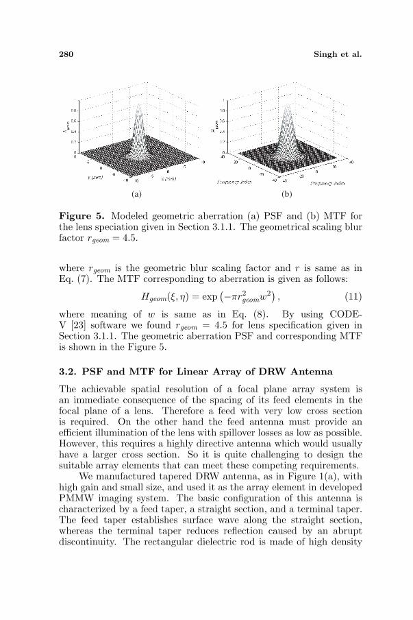
Figure 5. Modeled geometric aberration (a) PSF and (b) MTF forthe lens speciation given in Section 3.1.1. The geometrical scaling blurfactor rgeom = 4.5.
where rgeom is the geometric blur scaling factor and r is same as inEq. (7). The MTF corresponding to aberration is given as follows:
Hgeom(ξ, η) = exp(−πr2
geomw2), (11)
where meaning of w is same as in Eq. (8). By using CODE-V [23] software we found rgeom = 4.5 for lens specification given inSection 3.1.1. The geometric aberration PSF and corresponding MTFis shown in the Figure 5.
3.2. PSF and MTF for Linear Array of DRW Antenna
The achievable spatial resolution of a focal plane array system isan immediate consequence of the spacing of its feed elements in thefocal plane of a lens. Therefore a feed with very low cross sectionis required. On the other hand the feed antenna must provide anefficient illumination of the lens with spillover losses as low as possible.However, this requires a highly directive antenna which would usuallyhave a larger cross section. So it is quite challenging to design thesuitable array elements that can meet these competing requirements.
We manufactured tapered DRW antenna, as in Figure 1(a), withhigh gain and small size, and used it as the array element in developedPMMW imaging system. The basic configuration of this antenna ischaracterized by a feed taper, a straight section, and a terminal taper.The feed taper establishes surface wave along the straight section,whereas the terminal taper reduces reflection caused by an abruptdiscontinuity. The rectangular dielectric rod is made of high density

Progress In Electromagnetics Research B, Vol. 23, 2010 281
(a) (b)
Figure 6. Modeled DRW antenna (a) radiation pattern normalized,i.e., antenna PSF using CST (b) antenna MTF.
polyethylene (HDPE) and feeding is achieved by means of WR-10metallic waveguide transition. The developed DRW antenna has gainabout 15.3 dB and 10 dB bandwidth of 53.2◦ and 48.6◦ in E- and H-plane, respectively. The detail about the developed DRW antenna ispublished in [15].
3.2.1. Spatial Response of DRW Antenna in Linear Array
The radiation falling on the array element aperture, DRW antennaaperture, is spatially integrated. The DRW antenna aperture responseis not uniform over the aperture. The incident radiation is weightedby the antenna radiation pattern before integration. Therefore, theradiation pattern of the DRW antenna is the PSF hDRW(x, y) and itsFourier transform is the MTF. The PSF and MTF of the DRW antennain linear array are shown in Figure 6.
3.2.2. Electromagnetic Crosstalk PSF and MTF
The other component of the array element for the linear array of DRWantenna is the electromagnetic crosstalk, which is found by calculatingthe mutual impedance [20, 21]. The crosstalk arises when the radiationintended for a particular array element in array contributes or inducesa spurious signal on its neighbor. Crosstalk mechanism is illustrated inFigure 7. Conceptually, DRW antenna in linear array distance x apartand only the first DRW antenna receive electromagnetic radiation #0.Part of this incident radiation will be re-scattered into space #2, theother will directed towards neighboring DRW antenna as #3, whereit will add vertically with incident radiation on neighboring array

282 Singh et al.
element, and a part will travel into its feed as #1. Without directlyreceiving the incoming radiation, the neighboring array elements areexcited by scattered radiation #3 by the first array element. Thestrength of the induced signal in neighboring array element is relatedto the mutual impedance [20, 21]. Because the scattered electric field ofthe first array element falls off with the distance, the mutual impedancetends to decrease with increasing separation. The detail mathematicalanalysis of mutual crosstalk for antenna array is available in classicalpaper [20]. The mutual impedance, Z12, is calculated using equation(73) in [20], that is based on the plane wave spectrum of the far-fieldpower radiation pattern of the antenna. This method is convenient,because, although mutual impedance is a near field phenomenon, themethod in [20] requires only the knowledge of far-field power radiationpattern.
Figure 7. Schematic for the crosstalk between array elements in thelinear array of DRW antenna.
(a) (b)
Figure 8. Modeled array crosstalk. (a) PSF. (b) MTF with antennaspacing 5 mm.

Progress In Electromagnetics Research B, Vol. 23, 2010 283
We use the CST software to find out the mutual impedance forthe developed linear array with DRW antenna. And we found thatthe inter-element back-to-back crosstalk is −39 dB for array elementspacing 5 cm at 94GHz (≈ 1.5λ). The crosstalk PSF and MTF are asin Figure 8.
3.3. PSF and MTF of Sampling Subsystem
The focal plane of the developed imaging system is sampled usinglinear DRW antenna and scanning. The sampling interval dependson antenna spacing in DRW antenna array and scanning. For 2-dimensional rectangular sampling grid, the sampling PSF is rectanglefunction whose width is equal to the sampling interval in each direction:
hsh(x, y) = rect (x/xsamp, y/ysamp) , (12)
where xsamp, ysamp are sampling interval in x (scan direction) and ydirection, respectively. The sampling MTF:
Hsh (ξ, η)= |sinc (ξxsamp, ηysamp)|= sin (πξxsamp)πξxsamp
sin (πξysamp)πξysamp
. (13)
In the developed W-band PMMW imaging system, sampling intervalin y-direction is fixed and equal to distance between array element,while in x-direction it depends on integration time, scanning speed,and scene motion. Here, we assume that scene is not in motion, i.e.,image of scene in focal plane is static. In this case, the sampling intervalin x-direction is:
xsamp = vscanτ, (14)
(a) (b)
Figure 9. Modeled sampling. (a) PSF and (b) MTF for spacingbetween antenna in array is 5mm, i.e., ysamp = 5 mm, vscan =150mm/s, and τ = 10 ms.

284 Singh et al.
where vscan is the scan velocity, τ is the integration time. In thedeveloped system spacing between antenna in array is 5 mm, i.e,ysamp = 5mm, vscan = 150mm/s, and τ = 10ms. Thus, xsamp =1.5mm. The sampling PSF and MTF are shown in Figure 9.
4. MEASUREMENT AND OPTICAL PERFORMANCEANALYSIS
Figure 10 shows the schematic and experimental setup for themeasurement of the lens PSF and over all PSF for the quasi opticalpart used in the developed W-band PMMW imaging system. Thisexperiment setup was established for the near field measurement.We used W-band source generator with source locking counter and
Point Source
Power Meter
Figure 10. Schematic and photo of experimental setup for PSF andresolution measurement.

Progress In Electromagnetics Research B, Vol. 23, 2010 285
a pyramidal standard gain horn (SGH) (Millitech Co, aperture size24 × 18 mm2) as point source transmitter. SGH is mounted on ascanning stand, which is equipped with measurement scale in orderto get position of SGH from reference point (optical axis of lens). Thecombination of lens and DRW antenna array used as a receiver. The W-band power meter is attached to the end of DRW antenna in antennaarray to measure the received power.
This initial experiment setup is for fixing focal plane and imageplane. The SGH is fixed at a distance S1 = 2380 mm from lens and atheight same as optical axis of the lens. DRW antenna scanned alongoptical axis of the lens until the maximum output power of the feedwas observed by the W-band power meter. The maximum receivedpower was obtained at feed position S2 = 520 mm (Figure 10), and it isconsidered as beam focal point/image point of the lens correspondingto the source point. The focal length, f , was calculated using lensformulae, 1
S1+ 1
S2= 1
f , and found ≈ 427mm. The difference betweenthe measured focal length (427mm) and design focal length (500 mm)can be due to combined effect of following factors: i) Error in themeasurement of the dielectric constant of HDPE at W-band. ii) Dueto large size of lens, surface curvature is not correctly manufactured.iii) Spherical aberration. iv) Measurement error.
Next, the feed antenna (DRW) array is positioned at the focuspoint of the lens in order to measure the PSF, crosstalk effect,Rayleigh resolution limit, and diffraction limited nature of the imagingsubsystem.
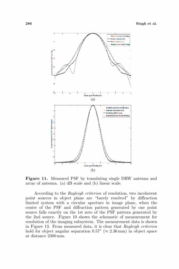
The PSF measured by translating the single feed antenna andantenna array in the focal plane for following two cases: i) using singlefeed antenna: Lens and feed antenna effect, and ii) using antennaarray: Lens, feed antenna, and crosstalk effect. Figures 11(a), 11(b)shows the cross section of simulated and measured PSF at dB andlinear scale. From simulation we found that the sampled-imagingsubsystem is almost symmetric, hence we presented a cross sectionPSF for analysis.
The modeled and measured PSF, h(x, y), for case i and ii areshown in Figure 11. The modeled and measured PSF closely agreedfor both cases. It is evident from Figure 11 that the measurementfor case i and ii differed nominally, thus crosstalk effect is almostnegligible, and hence, it is not serious problem for the developed DRWantenna array. The modulation transfer function (MTF) shown inthe Figure 12 corresponding to the PSF in Figure 11. The closeagreement between measurement and theoretical diffraction-limitedPSF and MTF curves indicates that the optics is diffraction-limitedand the pattern is adequately sampled.
286 Singh et al.
(b)
(a)
Figure 11. Measured PSF by translating single DRW antenna andarray of antenna. (a) dB scale and (b) linear scale.
According to the Rayleigh criterion of resolution, two incoherentpoint sources in object plane are “barely resolved” by diffractionlimited system with a circular aperture in image plane, when thecenter of the PSF and diffraction pattern generated by one pointsource falls exactly on the 1st zero of the PSF pattern generated bythe 2nd source. Figure 10 shows the schematic of measurement forresolution of the imaging subsystem. The measurement data is shownin Figure 13. From measured data, it is clear that Rayleigh criterionhold for object angular separation 0.57◦ (≈ 2.36 mm) in object spaceat distance 2380mm.

Progress In Electromagnetics Research B, Vol. 23, 2010 287
Figure 12. The MTF corresponding to the measured and simulatedPSF.
4.6 mm
4.6 mm
Figure 13. Measured power for object angular separation −0.57◦, 0◦,and +0.57◦ as in Figure 10.
Theoretically, the minimum resolvable separation in the imageplane is given as follows [17, 18]:
δ =1.22λf
D, (15)
where D is aperture diameter, λ is wavelength, and f is the focallength. Theoretical value of δ = 3.904mm for developed quasi opticssystem, while measured value is of resolvable separation in is 4.6mm.

288 Singh et al.
This error in theoretical and measurement may be measurement erroror due to effect of feed horn used during measurement.
5. CONCLUSION
This paper presents performance analysis of imaging system basedon linear array of focused receiver. This approach accounts for thecombined effect of dielectric lens, dielectric rod waveguide (DRW)antenna in array, crosstalk between DRW antenna in array, andsampling. We modeled these effects using concept of point spreadfunction (PSF) and modulation transfer function (MTF). And theperformance analysis of PMMW imaging system at W-band using PSFand MTF is presented.
As a case study, we used quasi optics based W-band PMMWimaging system that exploits a new type of DRW antenna, whichhas higher gain, in linear array of focused receiver. Antenna-to-antenna crosstalk causes a modest MTF decrease at low spatialfrequencies, where as the narrow PSF causes modest MTF gainat high frequencies. From simulation and measurement, we foundthat overall electromagnetic crosstalk will not be a significant imagequality/imaging performance factor in the used linear array of DRWantenna. Thus, the developed linear array with DRW antenna issuitable for passive imaging application at W-band.
An experimental setup for measuring PSF is presented. The closeagreement between measured and theoretical PSF and MTF curvesindicates that the system is diffraction-limited and the pattern isadequately sampled. We measured minimum resolvable separation inimage plane 4.6 mm, which is also close to the sampling by antennaarray (5 mm ≈ 1.5λ = 4.80mm). This also confirms the adequatesampling of the pattern. Thus, the proposed imaging system is efficientand it has almost diffraction limited resolution.
In this paper, we assumed that system is linear and shift-invariant(isoplanatic), i.e., the PSF (hence MTF) does not depend on thelocation and the strength of a point source. If the shift-invariantassumption is not valid, the image/response of point source, PSF,will depend on its location, and the system MTF will have spuriouslocation-dependent phase dependence. The test for shift-variant natureand PSF/MTF approach to system performance analysis for thedeveloped system is our future plan.
This paper is based on development of Millimeter wave ImagingRadiometer Equipment (MIRAE) [22] by Sensor System Laboratoryat GIST Republic of Korea.

Progress In Electromagnetics Research B, Vol. 23, 2010 289
ACKNOWLEDGMENT
This work was supported by the Dual Use Center and MillisysInc. (http://www.millisys.com) through the contract GM03980 at theGwangju Institute of Science and Technology and the BK-21 programof government of Republic of Korea. Thank to Dr. Tanveer J. Siddiqui,for many useful discussion in order to improve the overall paper quality.
REFERENCES
1. Yujiri, L., M. Schoucri, and P. Moffa, “Passive millimeter-waveimaging,” IEEE Microwave Magazine, Sep. 2003.
2. Wilson, W. J., R. J. Howard, and A. C. Ibbot, “Millimeter-wave imaging sensor,” IEEE Trans. on Microwave Theory andTechniques, Vol. 34, No. 10, 1026–1035, 1986.
3. Lovberg, J., R. Chou, and C. Martin, “Real-time millimeter-waveimaging radiometer for avionics synthetic vision,” Proc. SPIEConf. on Sensing, Imaging, and Vision for Control and Guidanceof Aerospace Vehicles, J. G. Verly and S. S. Welch (eds.), Vol. 2220,234–244, 1994.
4. Richter, J., D. Notel, F. Kloppel, J. Huck, H. Essen, and L.-P. Schmidt, “A multi-channel radiometer with focal plane arrayantenna for W-band passive millimeter wave imaging,” IEEEMTT-S Int. Microwave Symp. Dig., 2006.
5. Appleby, R., R. N. Anderton, S. Price, N. A. Salmon,G. N. Sinclair, J. R. Borrill, P. R. Coward, P. Papakosta,A. H. Lettington, and D. A. Robertson, “Compact real-time(video rate) passive millimeter-wave imager,” Proc. SPIE Conf.on Passive Millimeter-wave Imaging Technology III, Vol. 3703,13–19, 1999.
6. Yujiri, L., H. Agravante, M. Biedenbender, G. S. Dow,M. Flannery, S. Fornaca, B. Hauss, R. Johnson, R. Kuroda,K. Jordan, P. Lee, D. Lo, B. Quon, A. Rowe, T. Samec,M. Shoucri, K. Yokoyama, and J. Yun, “Passive millimeter-wavecamera,” Proc. SPIE Conf. on Passive Millimeter-wave ImagingTechnology, Vol. 3064, 15–22, Orlando, 1997.
7. Yujiri, L., H. Agravante, S. Fornaca, B. Hauss, R. Johnson,R. Kuroda, B. Quon, A. Rowe, T. Samec, M. Shoucri, andK. Yokoyama, “Passive millimeter wave video camera,” Proc.SPIE Conf. on Passive Millimeter-wave Imaging Technology II,Vol. 3378, 15–22, 1998.

290 Singh et al.
8. Rutledge, D. B. and M. S. Muha, “Imaging antenna arrays,” IEEETrans. on Antennas and Propagation, Vol. 30, No. 4, 1982.
9. Goldsmith, P. F., C. T. Hsieh, and G. R. Huguenin, “Focal planeimaging systems for millimeter wavelengths,” IEEE Trans. onMicrowave Theory and Techniques, Vol. 41, No. 10, 1664–1675,1993.
10. Qassim, K. A. S., “Optimization of focal plane arrays formicrowave imaging; printed yagi, dielectric rod and constantwidth slot antennas are investigated and optimized for closestacking in focal plane arrays intended for microwave imaging,”Ph.D. Dissertation, University of Branford, UK, Bradford, 1992.
11. Dow, G. S., T. N. Ton, H. Wang, D. C. W. Lo, W. Lam, B. Allen,K. L. Tan, and J. Berenz, “W-band MMIC direct detectionreceiver for passive imaging,” IEEE MTT-S Int. Microwave Symp.Dig., 163, 1993.
12. Kuroda, R. T., G. S. Dow, D. Moriarty, R. Johnson, A. Quil,S. D. Tran, V. Pajo, S. Fornaca, and L. Yujiri, “Large scale W-band focal plane array developments for passive millimeter waveimaging,” Proc. SPIE Conf. on Passive Millimeter-wave ImagingTechnology II, Vol. 3378, 75–62, Orlando, FL, 1998.
13. Richter, J. and L.-P. Schmidt, “Dielectric rod antennas asoptimized feed elements for focal plane array,” Proceeding of theIEEE AP-S International Antennas and Propagation Symposium,Vol. 3A/4, Washington, D.C., USA, Jul. 2005.
14. Lioubtchenko, D. V., S. N. Dudorov, J. Mallat, and A. V. Raisa-nen, “Dielectric rod waveguide antenna for W band with good in-put match,” IEEE Microwave and Wireless Components Letters,Vol. 15, No. 1, 2005.
15. Kim, W. G., J. P. Thakur, and Y.-H. Kim, “Efficient DRWantenna for quasi-optics feed in W-band imaging radiometersystem,” Microwave and Optical Technology Letters, Vol. 52,No. 5, 1221–1223, 2010.
16. Thakur, J. P., W.-G. Kim, and Y.-H. Kim, “High resolutionlarge aperture aspheric dielectric lens antenna for W-band quasi-optics,” Progress In Electromagnetics Research, PIER 103, 57–65,2010.
17. Vollmerhausen, R. H. and R. G. Driggers, Analysis of SampledImaging Systems, Vol. TT39, ISBN 0-8194-3489-2, SPIE Press,2000.
18. Boreman, G. D., Modulation Transfer Function in Optical andElctro-optical Systems, Vol. TT52, ISBN 0-8194-4143-0, SPIEPress, 2001.

Progress In Electromagnetics Research B, Vol. 23, 2010 291
19. Goodman, J. W., Introduction to Fourier Optics, McGraw-Hill,1997.
20. Wasylkiwskyj, W. and W. K. Kahn, “Theory of mutual couplingamong minimum-scattering antennas,” IEEE Trans. on Antennasand Propagation, Vol. 18, No. 2, 1970.
21. Balanis, C. A., Antenna Theory Analysis and Design, 3rd edition,Wiley & Sons, 2005.
22. Kim, W.-G., N.-W. Moon, Y.-J. Kim, J.-M. Jung, M.-K. Jung,Y.-S. Chang, M.-S. Park, and Y.-H. Kim, “Development of30 channels millimeter wave imaging radiometer equipment(MIRAE),” Proceeding of International Symposium on RemoteSensing, Busan, South Korea, Oct. 2009.
23. http://www.opticalres.com/.