optical lever for kagra - gwdoc.icrr.u-tokyo.ac.jp
TRANSCRIPT

Optical lever for KAGRA
Kazuhiro Agatsuma 2014/May/16
2014/May/16 GW monthly seminar at Tokyo 1

Contents
Optical lever (OpLev) development for KAGRA • What is the optical lever? • Review of OpLev in TAMA-SAS • Requirements of KAGRA • Selection of components • Layout • Performance test • Toward bKAGRA (cryo-condition)
2014/May/16 GW monthly seminar at Tokyo 2

What is the optical lever?
2014/May/16 GW monthly seminar at Tokyo 3

OpLev is an angular sensor used for • Local angular control of each mirror => to help lock acquisition of the interferometer • Monitoring drift motion
2014/May/16 GW monthly seminar at Tokyo 4
mirror
Position sensor
Light source

Principle
2014/May/16 GW monthly seminar at Tokyo 5
Archimedes "Give me a place to stand and I will move the earth!“ (http://www.buzzle.com/editorials/7-30-2004-57259.asp)
c.f. Lever
Optical lever
The mirror angle is increased by the distance of detection
mirror
Position sensor
Light source
Effort Load
Fulcrum The effort force is reduced by the distance of effort arm
L

OpLev looks easy! It looks a kind of LEGO. Does it need to research? => Yes.
Operation is easy but “suitable” setup is not obvious • to meet requirements (angular spectrum, drift, range) • easy maintenance (easily available) • reasonable price (10-20 OpLevs will be used) => suitable operation is achieved by accumulation of
experiences
2014/May/16 GW monthly seminar at Tokyo 6
mirror
Position sensor
Light source
♦To decide detail design of OpLev ♦Engineering test (prototype test)
Objectives

Review of OpLev in TAMA-SAS (Actual examples)
2014/May/16 GW monthly seminar at Tokyo 7

OpLev in TAMA-SAS
2014/May/16 GW monthly seminar at Tokyo 8
(2002, TAMA project report)
TAMA-SAS Position sensor: QPD (quadrant photo diode)

Sensitivity
2014/May/16 GW monthly seminar at Tokyo 9
There were some exercises to reach the left sensitivity ♦windshield ♦laser angle ♦cabling ♦etc…

Angular control by OpLev
2014/May/16 GW monthly seminar at Tokyo 10
(master thesis of K.A.)
Mirror angular motion was suppressed by OpLev control

KAGRA requirements
2014/May/16 GW monthly seminar at Tokyo 11

Requirement (spectrum)
(※) In this calculation, following parameters are assumed • Intensity noise of light source: RIN ~ 1e-7 /rtHz • Shot noise or dark noise: ~1e-11 m/rtHz (as the spot fluctuation)
2014/May/16 GW monthly seminar at Tokyo 12
by Michimura and Sekiguchi, JGW document (2012/4/27)
To lock IFO RMS: 0.1 urad (for cavity) RMS: 1 urad (for BS mirror)
Intensity noise, shot noise
Requirement

Requirement (drift, range)
2014/May/16 GW monthly seminar at Tokyo 13
To hold fringe for a day Drift: 10 urad/day
3 km
3 cm / 3km = 10 urad 10 urad/week? 10 urad/day? 10 urad/h? =>
3 cm
To be locked by referring to optical lever
remaining fringe
If commissioning phase is assumed
Drift
Range
To follow unstable condition Range: 1~10 mrad (according to VIRGO empirically)
If the local control is failure (turned off), the suspension system is fluctuated

Selection of components
2014/May/16 GW monthly seminar at Tokyo 14

Selection of components • Light source
– SLD (Super Luminescent Diode) – Center wave length: 670 nm – Thermal control is included – Power: 1 mW
• Collimator lens – Beam-spot size: it affects the linear range and sensitivity ⇒ 0.5 - 2 mm for PSD (c.f. 2mm in case of aLIGO)
• Photo receiver – PSD (Position Sensitive Detector) – Φ: 9 mm x 9 mm
2014/May/16 GW monthly seminar at Tokyo 15
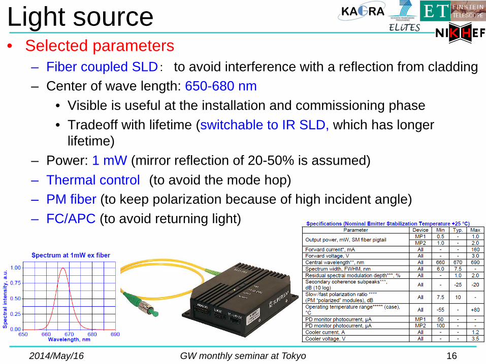
Light source • Selected parameters
– Fiber coupled SLD: to avoid interference with a reflection from cladding – Center of wave length: 650-680 nm
• Visible is useful at the installation and commissioning phase • Tradeoff with lifetime (switchable to IR SLD, which has longer
lifetime) – Power: 1 mW (mirror reflection of 20-50% is assumed) – Thermal control (to avoid the mode hop) – PM fiber (to keep polarization because of high incident angle) – FC/APC (to avoid returning light)
2014/May/16 GW monthly seminar at Tokyo 16
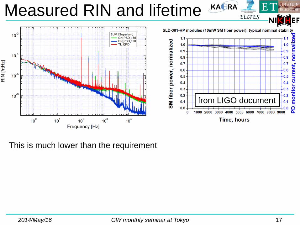
Measured RIN and lifetime
2014/May/16 GW monthly seminar at Tokyo 17
This is much lower than the requirement
from LIGO document

Position sensor
PSD (Position Sensitive Detector) • Large linear dynamic range • Low speed response • Spot-size-independent sensitivity
QPD (Quadrant Photo Detector) • Small linear dynamic range • High speed response • Spot-size-dependent sensitivity
2014/May/16 GW monthly seminar at Tokyo 18
Performance has been checked for below candidates
(※ Spot size affects the linear dynamic range)

Calibration factors
2014/May/16 GW monthly seminar at Tokyo 19
Φ 2mm: linear range: 7mm Φ 0.5mm: linear range: 8mm
Sensitivity is independent on the spot size => easy adjustment Linear range of PSD (7mm) is much larger than that of QPD (0.5mm)
PSD: 7 mm (Φ 2 mm) QPD: 0.5-1.5 mm (Φ 2-6 mm)
X-Y stage PSD (Position Sensitive Detector) Φ: 9 mm x 9 mm

Launcher (collimator lens & mirror)
Selected launcher Spot size is 1-2 mm with the
working distance of 4m • Adjustable-focus lens (good match with PSD)
2014/May/16 GW monthly seminar at Tokyo 20
Initial steering mirror

Layout
2014/May/16 GW monthly seminar at Tokyo 21

Optical layout
2014/May/16 GW monthly seminar at Tokyo 22
mirror
Position sensor
Light source
mirror
mirror
Turning mirror
Length coupling
θ
Large θ causes length coupling

Layout design
2014/May/16 GW monthly seminar at Tokyo 23
BS
Option 1 (Mixed signal)
Option 2 (Broad range & length)
BS
Default
Input port
Turning port
Range: 8mm/(2*3m) = 1.3 mrad
lens
Range: 8mm/(2*1m) = 4 mrad
PSD
Chamber for Type-B SAS

Turning port
2014/May/16 GW monthly seminar at Tokyo 24
BS
Option 1 (Mixed signal or Length information)
Option 2 (Broad range & Length)
BS
lens
PSD PSDs have to be placed on the focal plane and image plane using sliders with about 10-um accuracy
Merit: Clear separation between longitudinal and angular motion Demerit: Extra optics (PSD, lens and their sliders) increase total cost.
Subtraction of angular signal (input port) from the mixed PSD output produces the longitudinal signal
Merit: Cheap and simple Demerit: Direct coupling between longitudinal and angular motion
Option 1.5 lens (Broad range or Length information) To adjust the focal or image plane by adding a lens
Option 1 Option 1.5 Option 2
Cost Low Middle High
Information Mix or Length Broad or Length Broad and Length

Layout design for Type B (preliminary)
2014/May/16 GW monthly seminar at Tokyo 25
Drown by Gianni Gennaro
Breadboard

Performance test
2014/May/16 GW monthly seminar at Tokyo 26

Comprehensive drift (NAOJ)
2014/May/16 GW monthly seminar at Tokyo 27
~1m
PSD
Thermometer Paper box was used as windshield

Comprehensive drift (NAOJ)
2014/May/16 GW monthly seminar at Tokyo 28
Fitting: Y = α + β*T + γ*(x – t) T: temperature, β: temperature response x: time, γ: constant drift t: time delay
X direction: β = 8 um/K, γ = 14 um/day => 2 urad/day Y direction: β = 50 um/K, γ = 170 um/day => 30 urad/day (3m OpLev length)
To hold fringe for a day Drift: 10 urad/day
Origin of this drift is in investigation

2014/May/16 GW monthly seminar at Tokyo 29
Comprehensive drift (Nikhef)
~1m
Windshield
PSD
SLD
Thermometer (Pt100)

Comprehensive drift (Nikhef)
2014/May/16 GW monthly seminar at Tokyo 30
Fitting function: Y = α + β×T + γ×(x – t) T: temperature, β: temperature response x: time, γ: constant drift t: time delay
X direction: β = 44 um/K, γ = 6.4 um/day => 0.7 urad (0.1K/day in Kamioka) + 1 urad(drift) = 1.7 urad/day (OpLev length of 3m is assumed)
Y direction: β = 600 um/K, γ = 13um/day => 10 urad (0.1K/day) + 2 urad(drift) = 12 urad/day (OpLev length of 3m is assumed)
These results almost achieved the requirement of KAGRA (10 urad/day)
Temperature control in lab.
25 min.

Comparison with NAOJ result
2014/May/16 GW monthly seminar at Tokyo 31
NAOJ (talk at 2nd ELiTES meeting)
Condition is better than NAOJ ♦all mirror use thread-pitch locks ♦temperature is stable in the clean room ♦heavy optical table ♦metal windshield
X
Y
Nikhef

Spectrum of spot fluctuation
2014/May/16 GW monthly seminar at Tokyo 32
limited by digitization noise Thermal drift is seen below 0.1 Hz
worse than X direction => mechanical vibrations
Optical lever length of 3 m is assumed => divided by factor of 6 => ~ 1 nrad/rtHz at 1 Hz

Intensity noise by offset
2014/May/16 GW monthly seminar at Tokyo 33
Consistent with RIN measurement within difference factor of 2 (The left response has two times smaller RIN than the right graph shows) => an individual difference of SLD
(Blue line)

Investigation of large thermal response
2014/May/16 GW monthly seminar at Tokyo 34
?
Short length setup ⇒ Scaling factor only? ⇒ Scaling factor + bending?
The temperature response of Y direction is relatively worse: (X: β = 44 um/K, Y: β = 600 um/K)
Table bending?

Investigation of large thermal response
2014/May/16 GW monthly seminar at Tokyo 35
(2.5 + 98) + 104 + 104 + 111 + 29 cm = (100.5) + 348 cm, d1 = 111 cm Optical path length: 449 cm OpLev length: 348 cm Return mirror OpLev: 244 cm
(2.5 + 12) + 29 + 29 + 27 + 29 cm = (14.5) + 114 cm, d2 = 29 cm Optical path length: 129 cm OpLev length: 114 cm Return mirror OpLev: 85 cm
Lspot = 2x(4.5xθ1 + 3.5xθ2 + 2.4xθ3) Sspot = 2x(1.3xθ1 + 1.1xθ2 + 0.9xθ3)
d1 d2
Lspot /Sspot = ~3: Scaling factor (θ1=θ2=θ3)
d1/d2 = 3.8 : Table deformation factor
Which is the real factor? 3 (dominated by local mirrors) or 3x3.8=11 (dominated by table deformation)
θ1 θ2
θ3

Short length measurement
2014/May/16 GW monthly seminar at Tokyo 36
Short: β = 44 um/K, γ = 0.6 um/day (Long: β = 44 um/K, γ = 6.4 um/day)
Fitting function: Y = α + β×T + γ×(x – t) T: temperature, β: temperature response x: time, γ: constant drift t: time delay
Short: β = 45 um/K, γ = 1.9 um/day (Long: β = 600 um/K, γ = 13 um/day)
x13 x7 x10
Y temp: Table bending dominant Y drift: Table bending dominant (almost)
x1
X Y
X temp: Translational motion of SLD or PSD X drift: Table bending dominant
Expected drift (scaling factor: x3 for 3m length, 0.1 K/day) X: β = 44 um/K, γ = 2 um/day => ~1 urad/day Y: β = 150 um/K, γ = 6 um/day => ~3 urad/day

Next step
2014/May/16 GW monthly seminar at Tokyo 37
Pylon

Toward bKAGRA (perspective for cryogenic system)
2014/May/16 GW monthly seminar at Tokyo 38

Layout
2014/May/16 GW monthly seminar at Tokyo 39
test mass chamber for iKAGRA
test mass chamber for bKAGRA
~15 m

Layout for iKAGRA
2014/May/16 GW monthly seminar at Tokyo 40
~ 1 m
OpLev length: 3m Optical path length: 4m
Pylon
Range: 8mm/(2*3m) = 1.3 mrad
Input port
Turning port

Layout for bKAGRA
2014/May/16 GW monthly seminar at Tokyo 41
~ 15 m
OpLev length: 15 m Optical path length: 30 m
aLIGO
Pylon
Range: 8mm/(2*15m) ~ 0.3 mrad !
Detection port
Design of collimator lens will be needed
Observable range becomes small (1.3 mrad => 0.3 mrad)

OpLev inside cryostat
2014/May/16 GW monthly seminar at Tokyo 42
Merit inside cryostat ♦Observing Intermediate mass ♦Short length OpLev (broad range)
Technical misc. ・No optical window ・Fiber coupled SLD is useful ・Cryo-compatible PD What should be the reference? - Cryostat => deformation by changing temperature - Making special pylon (super invar?) => difficult…
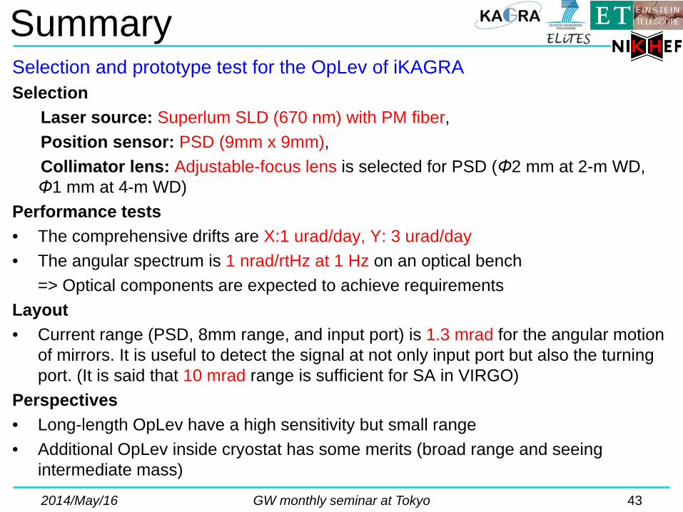
Summary Selection and prototype test for the OpLev of iKAGRA Selection Laser source: Superlum SLD (670 nm) with PM fiber, Position sensor: PSD (9mm x 9mm), Collimator lens: Adjustable-focus lens is selected for PSD (Φ2 mm at 2-m WD,
Φ1 mm at 4-m WD) Performance tests • The comprehensive drifts are X:1 urad/day, Y: 3 urad/day • The angular spectrum is 1 nrad/rtHz at 1 Hz on an optical bench => Optical components are expected to achieve requirements Layout • Current range (PSD, 8mm range, and input port) is 1.3 mrad for the angular motion
of mirrors. It is useful to detect the signal at not only input port but also the turning port. (It is said that 10 mrad range is sufficient for SA in VIRGO)
Perspectives • Long-length OpLev have a high sensitivity but small range • Additional OpLev inside cryostat has some merits (broad range and seeing
intermediate mass)
2014/May/16 GW monthly seminar at Tokyo 43

Acknowledgements
• Riccardo DeSalvo • Ettore Majorana • Ryutaro Takahashi • Tomotada Akutsu • Takanori Sekiguchi all member of VIS, AOS, and QND group.
2014/May/16 GW monthly seminar at Tokyo 44