optical fibres - · pdf fileece 455 – lecture 04 3 types of optical fibre we can...
TRANSCRIPT

ECE 455 – Lecture 04 1
Optical Fibres - Introduction
• HMY 445 • Lecture 04 • Fall Semester 2016
Stavros Iezekiel Department of Electrical and
Computer Engineering
University of Cyprus

ECE 455 – Lecture 04
OPTICAL FIBRES – THE BASICS
2

ECE 455 – Lecture 04 3
Types of Optical Fibre
We can subdivide the different types of optical fibre in many ways, for example: • Material: Plastic, glass or glass and plastic.
• Mode of Propagation: Single-mode or multimode. Light can only propagate through
certain modes – hence in a multimode fibre there are different modes (ways) the light can propagate.
• Refractive index profile: Step-index, graded index or double-clad (including triangular)
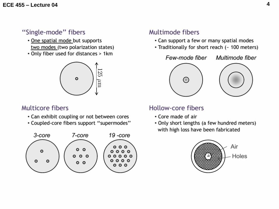
There are also other more “specialised” fibres, such as photonic crystal fibres, holey fibres and multicore fibres. So we see that even though we started to discuss optical fibres in lectures 01 – 03 from a general system perspective (e.g. looking at attenuation and link power budget), the subject of optical fibres is large and covers many aspects.
ECE 455 – Lecture 04 4
ECE 455 – Lecture 04 5
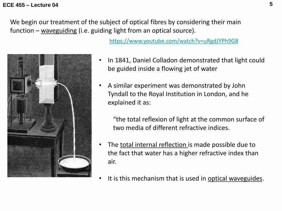
https://www.youtube.com/watch?v=uRgdJYPh9G8
• In 1841, Daniel Colladon demonstrated that light could be guided inside a flowing jet of water
• A similar experiment was demonstrated by John Tyndall to the Royal Institution in London, and he explained it as:
“the total reflexion of light at the common surface of two media of different refractive indices.
• The total internal reflection is made possible due to
the fact that water has a higher refractive index than air.
• It is this mechanism that is used in optical waveguides.
We begin our treatment of the subject of optical fibres by considering their main function – waveguiding (i.e. guiding light from an optical source).

ECE 455 – Lecture 04 6
A waveguide is a structure that is used to guide electromagnetic waves by confining them so as to allow propagation, e.g.:
Rectangular metallic waveguide, used at microwave frequencies. The dimensions (a, b) of the waveguide cross-section are important – they determine the frequencies at which the waveguide can be used. The electromagnetic waves propagate through various modes that must “fit” the geometry:
Electric field Ex component of the TE31 mode inside an X-band hollow metal waveguide.

ECE 455 – Lecture 04 7
For the example of a parallel plate waveguide, we can see how the wave is guided by total internal reflection from either plate, which sets up a pair of waves that then add up to produce a wave travelling along the axis of propagation.
http://demonstrations.wolfram.com/ElectromagneticWavesInAParallelPlateWaveg
uide/

ECE 455 – Lecture 04 8
Total internal reflection is also the mechanism that is used to guide electromagnetic waves (i.e. light) in an optical waveguide. Here, the materials used are dielectrics (or semiconductors). For example, we can fabricate planar optical waveguides (semiconductor-based):
These however are only suitable for chip-scale applications such as diode lasers and integrated photonics
Light
n 2
n 2
n 1 > n 2
Light
Light Light
z Propagation direction
x
y
ECE 455 – Lecture 04 9
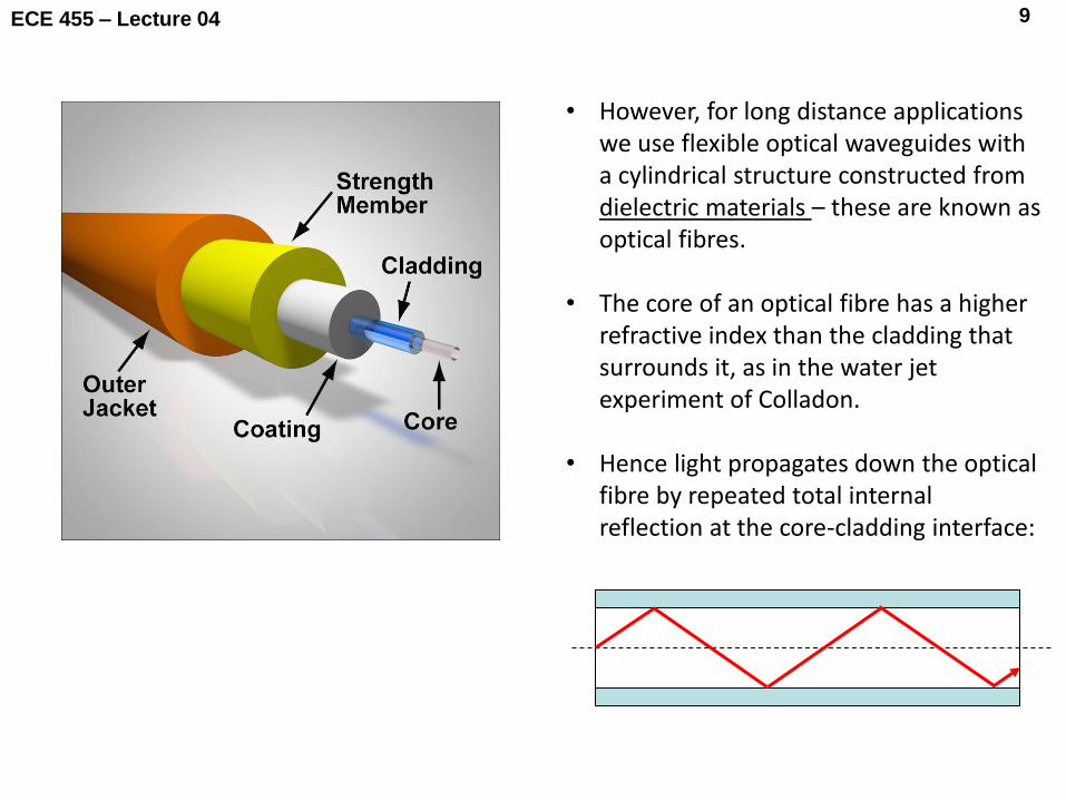
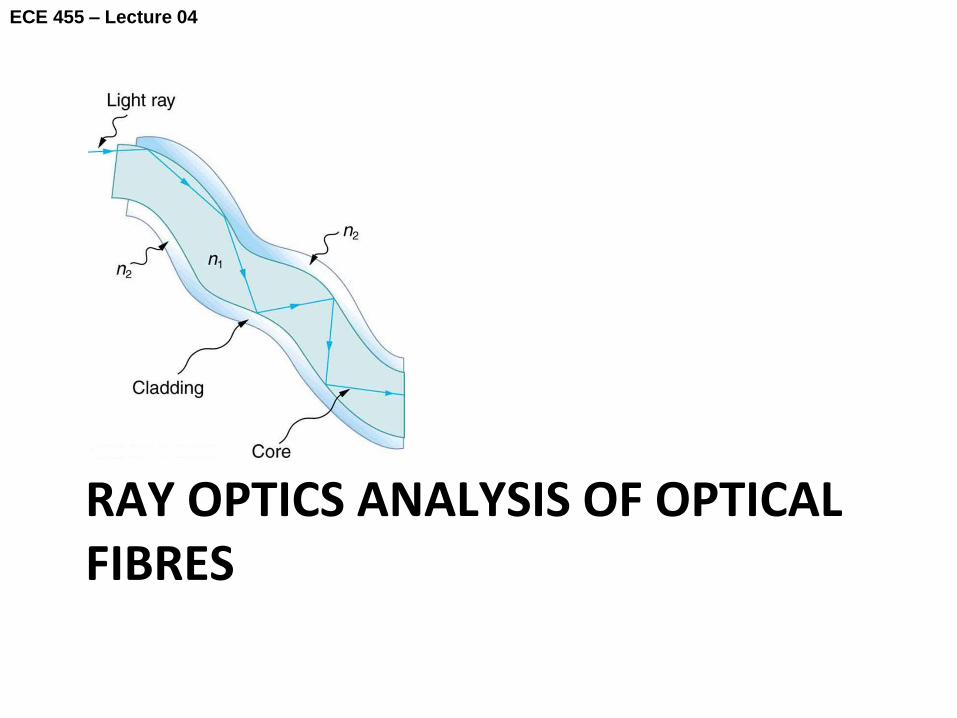
• However, for long distance applications we use flexible optical waveguides with a cylindrical structure constructed from dielectric materials – these are known as optical fibres.
• The core of an optical fibre has a higher refractive index than the cladding that surrounds it, as in the water jet experiment of Colladon.
• Hence light propagates down the optical fibre by repeated total internal reflection at the core-cladding interface:

ECE 455 – Lecture 04 10
• The two main dielectric materials that are used to fabricate optical fibres are plastic and glass (specifically silica glass – SiO2).
• Fibre cross-sections come in various sizes according to the application:
Core Cladding
Relative sizes of different fibre types POF = plastic optical fibre HCS = hard clad fibre (silica fibre core, plastic cladding), also known as plastic clad fibre (PCF) Note the relatively small core size of single mode fibre compared to the cladding. Silica

ECE 455 – Lecture 04 11
• Although the structure of an optical fibre looks very simple, we should be aware that this is a precision piece of engineering, especially for single mode fibre which has a typical core diameter of between 8 m and 10 m:
Comparison between cross sectional size
of a human hair and the core of a single mode fibre
• This precision is also reflected in the design of an optical fibre and the fabrication process.
• The relative size of components is also important in terms of how we analyse them; specifically we are interested in how the component size compares with the wavelength.
ECE 455 – Lecture 04 12
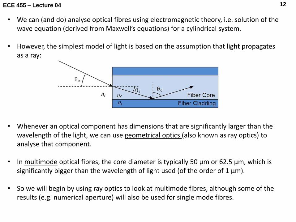
• We can (and do) analyse optical fibres using electromagnetic theory, i.e. solution of the wave equation (derived from Maxwell’s equations) for a cylindrical system.
• However, the simplest model of light is based on the assumption that light propagates as a ray:
• Whenever an optical component has dimensions that are significantly larger than the wavelength of the light, we can use geometrical optics (also known as ray optics) to analyse that component.
• In multimode optical fibres, the core diameter is typically 50 μm or 62.5 μm, which is significantly bigger than the wavelength of light used (of the order of 1 μm).
• So we will begin by using ray optics to look at multimode fibres, although some of the results (e.g. numerical aperture) will also be used for single mode fibres.
ECE 455 – Lecture 04
RAY OPTICS ANALYSIS OF OPTICAL FIBRES
13

ECE 455 – Lecture 04 14
t
i r
1n
2n
• We begin by defining the refractive index (n) of a material by:
• Here v is the speed of light in the material, which is less than the speed of light in vacuo c.
• We then examine what happens at the interface between two different materials with:
• From an approach based on electromagnetics, we can obtain these laws:
v
cn
21 nn
ri
ti nn sinsin 21
Law of reflection
Law of refraction (Snell’s law)
(1)
(2)
(3)
ECE 455 – Lecture 04 15
1 = C
n1
n2
1
1 > C 1 < C
n1
n2 2
1
n1
n2
1
2=900
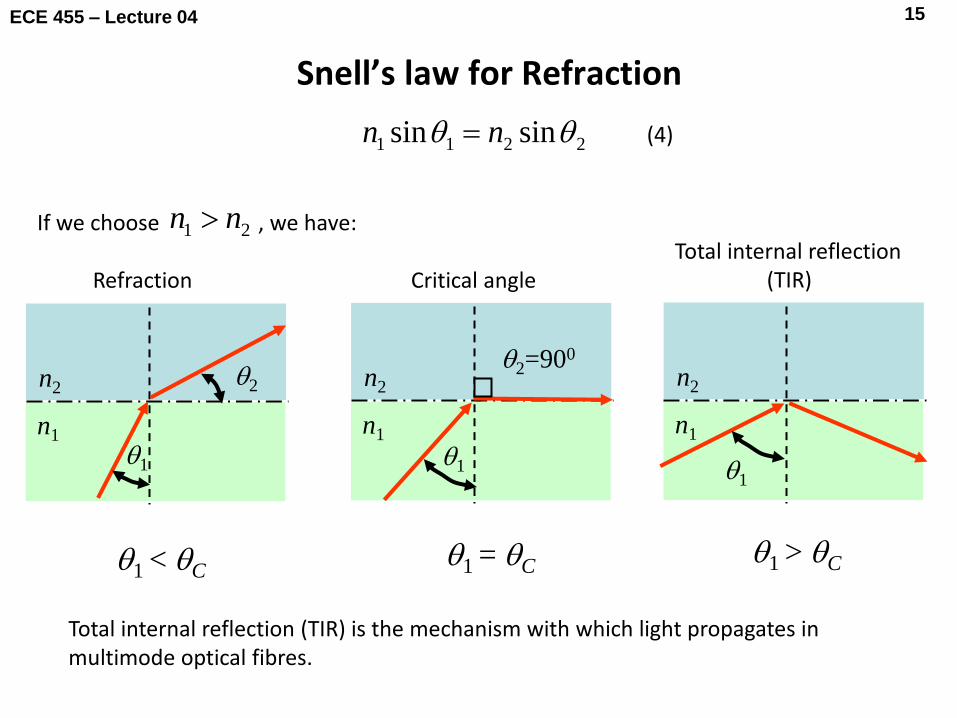
Total internal reflection (TIR) is the mechanism with which light propagates in multimode optical fibres.
Refraction Critical angle Total internal reflection
(TIR)
Snell’s law for Refraction
2211 sinsin nn
21 nn If we choose , we have:
(4)
ECE 455 – Lecture 04 16
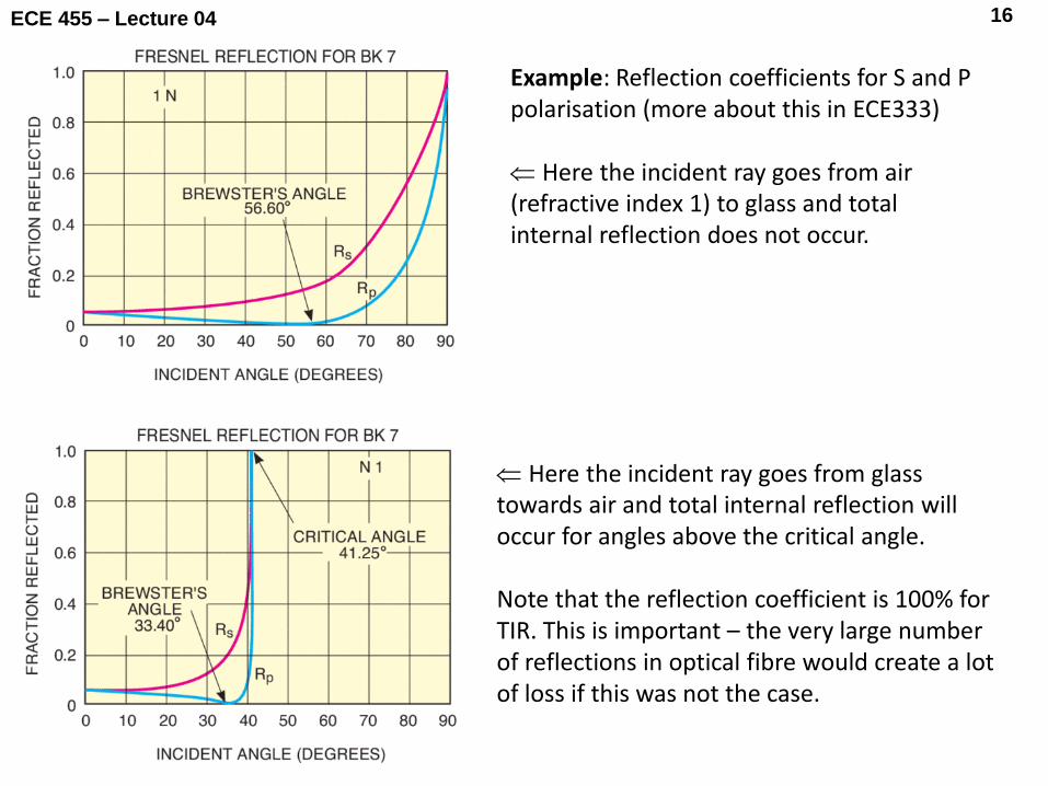
Example: Reflection coefficients for S and P polarisation (more about this in ECE333) Here the incident ray goes from air (refractive index 1) to glass and total internal reflection does not occur.
Here the incident ray goes from glass towards air and total internal reflection will occur for angles above the critical angle. Note that the reflection coefficient is 100% for TIR. This is important – the very large number of reflections in optical fibre would create a lot of loss if this was not the case.
ECE 455 – Lecture 04 17
n1
n2
C 1
n2
1 1 1 1 1 11
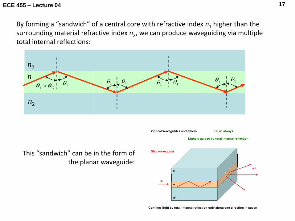
By forming a “sandwich” of a central core with refractive index n1 higher than the surrounding material refractive index n2, we can produce waveguiding via multiple total internal reflections:
This “sandwich” can be in the form of the planar waveguide:
ECE 455 – Lecture 04 18
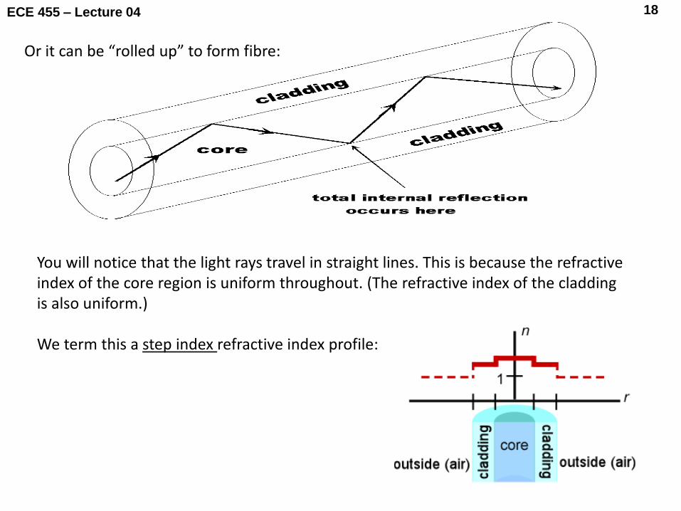
Or it can be “rolled up” to form fibre:
You will notice that the light rays travel in straight lines. This is because the refractive index of the core region is uniform throughout. (The refractive index of the cladding is also uniform.) We term this a step index refractive index profile:
ECE 455 – Lecture 04 19
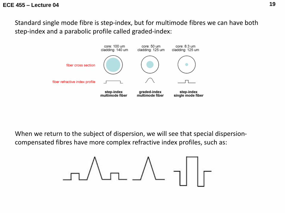
Standard single mode fibre is step-index, but for multimode fibres we can have both step-index and a parabolic profile called graded-index:
When we return to the subject of dispersion, we will see that special dispersion-compensated fibres have more complex refractive index profiles, such as:

ECE 455 – Lecture 04 20
We usually use laser diodes for high performance optical links. The light
from a laser diode actually diverges:
Provided the light from the laser can be coupled into the entrance
of the fibre within the correct range of angles, the light will
propagate within the fibre.
We say that the light must be within the acceptance angle of
the fibre:

ECE 455 – Lecture 04 21
Note: previous pictures and also the analysis to follow assumes meridional rays:
http://www.fiberoptic.institute/fiber-optic-guide/light-propagation-through-optical-fiber/

ECE 455 – Lecture 04 22
Does not propagate; < critical angle at core-cladding interface
Propagates through repeated TIR at core-cladding interface;
0 denotes the acceptance angle.
Propagation in an ideal step-index fibre
Air n0
Cladding
Core
Cladding
n1
n2
n2
n1 > n2 > n0
0
Reflected ray
Refracted ray

ECE 455 – Lecture 04 23
Numerical aperture (NA) in a step-index fibre
What is the maximum acceptance angle 0?
Apply Snell’s law:
sinsin 100 nn 21 sin nn C C
0
Cladding n2
Core n1
Air n0
2 C

ECE 455 – Lecture 04 24
2
2
2
1
2
1
21
2
1
1
1
100
1
sin1
cos
)2(sin
sinsin
nn
n
nn
n
n
n
nn
C
C
C
This equation defines the numerical aperture (NA) of a step-index fibre:
21 sin nn C C
0
Cladding n2
Core n1
2 C
2
2
2
100 sinNA nnn
(5)
(6)
ECE 455 – Lecture 04 25
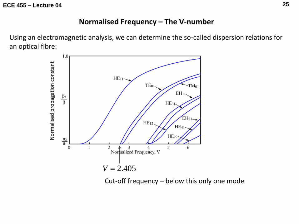
Normalised Frequency – The V-number
Using an electromagnetic analysis, we can determine the so-called dispersion relations for an optical fibre:
405.2V
Cut-off frequency – below this only one mode
No
rmal
ised
pro
pag
atio
n c
on
stan
t

ECE 455 – Lecture 04 26
For a step-index fibre, the normalised frequency or V-number is related to the numerical aperture by:
NAannaV .22 2
2
2
1
Core radius
The fibre is single mode if V < 2.405. Above this number, the number of modes rises quickly:
22
2/
VM
Number of modes
(7)
(8)

ECE 455 – Lecture 04 27
405.2.22 2
2
2
1 NAanna
From equation (7), we have multimode operation if:
If we have either a large numerical aperture or a large core radius (a) or both, then we will end up with multimode operation. In terms of ray optics, this leads to a picture as follows:
Animation 01

ECE 455 – Lecture 04 28
input t
+
+
=
t
t output
The problem with step-index multimode fibres is that the different modes (i.e. ray paths) all have the same speed (uniform refractive index) but they travel different distances for a fibre of length L (because of different angles of TIR). So if a pulse is launched into a fibre and excites multiple modes, we end up with pulse broadening:
This is called intermodal dispersion (or multimode dispersion):
Animation 02

ECE 455 – Lecture 04 29
We can try to minimise intermodal dispersion by using an optical fibre with a graded index profile:
n 1
n 2
2 1
3
n O
n 1
2 1
3
n
n 2
O O ' O ' '
n 2
2 3
Replace this (step index multimode):
with this (graded index multimode):

ECE 455 – Lecture 04 30
n 1
2 1
3
n
n 2
O O ' O ' '
n 2
2 3
Animation 03
Light on path 3 (blue) covers a greater overall distance than path 2 (red) or path 1 (green), but because of the varying refractive index, all three paths have the same average speed and exit the fibre at the same time.
ECE 455 – Lecture 04 31
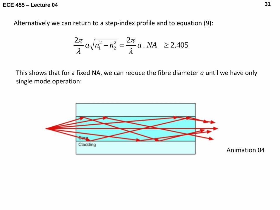
Alternatively we can return to a step-index profile and to equation (9):
405.2.22 2
2
2
1 NAanna
This shows that for a fixed NA, we can reduce the fibre diameter a until we have only single mode operation:
Animation 04

ECE 455 – Lecture 04 32
Refractive index profile
Fibre cross sections & ray paths
Typical dimensions
125 μm cladding
8 - 12 μm
core
n
n1 n2
Step-index single mode
125 - 400 μm cladding
50 - 200 μm
core n
n1 n2
Step-index multimode
125 – 140 μm cladding
50 - 100 μm
core n
n1 n2
Graded index multimode
Hence we have now seen three types of optical fibre: