optical fiber eigenvalue equation: plane wave derivation
TRANSCRIPT

Optical fiber eigenvalue equation: plane wave derivation
John D. Love and Allan W. Snyder
The asymptotic form of the eigenvalue equation for optical waveguides of circular cross section is derived
using only plane wave concepts, i.e., phase changes, Fresnel's and Snell's laws. Both step and parabolic re-fractive index profiles are treated using this method.
1. Introduction
The eigenvalue equation for optical waveguides isderived from Maxwell's equations by demanding thatthe electromagnetic fields satisfy the boundary con-ditions at the core-cladding interface.1'2 For the spe-cial case of the slab waveguide, it can also be derivedexactly using only plane wave considerations.3 Thisis not surprising, since the fields of the slab wave-guide are elementary superpositions of plane waves,unlike, for example, the fields of the waveguide of cir-cular cross section. 1'2 However, for multimode wave-guides of circular cross section the fields are locallyplane waves. Thus, as we show here, the asymptoticform of the eigenvalue equation results from elemen-tary plane wave considerations, i.e., phase changes,Fresnel's and Snell's laws.
II. Description of the Method
The philosophy of the method assumes that wavespropagate in the core of the multimode waveguidealong a basic path, the length of which is repeatedalong the whole length of the waveguide. Thus, forthose waveguides we examine in Secs. III-V, thebasic pathlengths are (a) PRQ along the zigzag pathfor the symmetric slab waveguide shown in Fig. 1, (b)the straight path PQ between successive reflectionsat the core-cladding interface on the helicoid path forthe step-index waveguide of circular cross section(Fig. 2), and (c) the curved path PQ on the parabolicindex waveguide of circular cross section betweensuccessive points at which the helicallike wave pathtouches the inner caustic in Fig. 3. We determinethe accumulated phase changes due to optical path-lengths, reflections, and caustics, of a plane wavepropagating along the path from P to Q in each case.4-6
The authors are with the Australian National University, De-partment of Applied Mathematics, Canberra, ACT, Australia2601.
Received 31 March 1975.
Components of phase change following the wavepath are comprised as follows. In traveling a distances along a path, a wave undergoes a phase change
A = fS k(r)ds,0
(1)
where the wavenumber k(r) = 2rn(r)/X. The wave-length in vacuum is X, and n (r) is the refractive indexin the core at the point with position vector r.
In examples in Secs. III and IV the core index niand the cladding index n2 are constant, with n2 < nl.At the core-cladding interface there is a phase changeOR upon reflection of the plane wave, for angles of in-cidence a > a, where the critical angle a, = sin-1
(n2/nl). When nj 1 n2, which is the case for opticalfibers of practical interest, Fresnel's laws for a planarinterface show2
pR - -2 arctan[(sin2 a - sin2 aU)V2/cosa,] (2)
independent of wave polarization.For waveguides of circular cross section, there is an
additional phase change Xc = -7r/2 whenever thewave touches a caustic. 4 Figure 4 shows the innercaustic in the cross section of the step-index wave-guide of circular cross section.
A second calculation of the total phase change be-tween P and Q goes as follows. We determine thegeometrical transformation of rotation and transla-tion of the wave path that moves P to Q in the wave-guide and leaves the wave path invariant. Thus, onthe slab waveguide the transformation is a transla-tion parallel to the waveguide (Fig. 5), while on thewaveguide of circular cross section it comprises botha translation parallel to the waveguide axis and arotation about the axis in the circular cross section.Figure 6 shows the rotation of the wave path for thestep index waveguide of circular cross section.
For waveguides with refractive index profiles thatare either constant or a function of the radial dis-tance from the waveguide axis only, the phase changeassociated with translation is defined as the productof the length of the straight path followed by P and
September 1976 / Vol. 15, No. 9 / APPLIED OPTICS 2121

d
Fig. 1. The zigzag path of a plane wave propagating at angle ofincidence a along the symmetric slab waveguide of thickness dwith core index of refraction ni and cladding index of refraction n2
< n. Reflection points P. Q, and R are denoted by the smallcircles.
.................................:/ < n. ~Q
... .. .. .. .. .. .. ... .-
.................... ................... .. .. ... ... .. .... .. .. .. ... ... .. .. .. .. .. .. .. ... .. .................
the component of the wave vector parallel to the path(z direction). Under rotation the phase change is de-fined as the product of the circular arc length in thecore and the component of the wave vector at the ini-tial position of P tangential to the circular cross sec-tion, i.e., in the x direction in Fig. 2. The total phasechange is the sum of the linear and rotational phasechanges.
When the refractive index profile takes neither ofthe above forms, the simple formulas for the transla-tional and rotational phase changes are replaced byequivalent integral definitions.
The eigenvalue equation is obtained by demandingthat the difference in the total phase changes as cal-culated by the two methods be an even multiple of r.
Taken together these facts enable us to derive theeigenvalue equations for the two waveguides. Al-though the slab waveguide equation has been derivedby several methods,2 '6 we give our derivation to es-tablish the above technique.
Ill. Slab Waveguide
With reference to Fig. 1, the symmetric slab wave-guide of thickness d has an optical pathlength PRQ= 2k id/cosa between repetitive reflection points.
Fig. 2. The helicoid path of a plane wave propagating along thewaveguide of circular cross section, core index of refraction ni,
cladding index of refraction 2 < n, and radius p.
P _Z....................... .....7. /\......... R ........... .......... .. ...... ;:; .
n (r)
Fig. 3. The helicallike path of a ray path in the core of the para-bolic index waveguide. P and Q are successive points where thepath touches the inner caustic radius ro. The z axis is parallel tothe waveguide axis, the x axis is in the azimuthal direction at P,
and the path makes angle with the z axis at P.
Pa
n2
Q
Fig. 4. An end on view of Fig. 2 showing the wave paths touchingthe caustic, depicted as the broken circle. The caustic is the enve-lope of the family of rays all making the same angles a and at
the interface.
Fig. 5. The translation Az of the wave path on the slab waveguidenecessary for P - Q and for the wave path to remain invariant.
n2
Pi\
Fig. 6. The rotation Ai/ of the wave path necessary for P - Qand for the wave path to remain invariant on the waveguide of cir-
cular cross section.
2122 APPLIED OPTICS / Vol. 15, No. 9 / September 1976
..... ....... ::::::: ... P :::::: .... ................ ::: ............:::::: ......... ............... ::::.................................................
To calculate the phase change due to reflections, werefer to points infinitesimally close to, but just be-yond, P and Q on the wave path, so that there is aphase change OR at both R and Q, and the opticalpathlength is unchanged. This is the total phasechange between P and Q. The geometrical transfor-mation that moves P to Q and leaves the wave pathinvariant consists of a translation along the z axis ofmagnitude PQ = 2d tana. The wave vector compo-nent in the z direction at P is k1 sina, leading to aphase change of 2k id sina tana due to translation ofthe reflection point. Since the two phase change cal-culations are equivalent to within even multiples ofor, we have
2kld/cosa + 2R = 2k1d sina tanc + 2N7r, (3)
where N = 0, L1, .... Substituting for OR from Eq.(2) and rearranging
tan(kid cosa/2) = (sin2a - sin2a)l/1/cosa (4a)
for the even modes, and
tan(kid cosa/2) -cosa/(sin2 a - sina,)Y/2 (4b)
for the odd modes.To relate Eq. (2) to the result of electromagnetic
theory, we observe that the latter has fields with zdependence of the form exp(iflz). Thus the z com-ponent of the wave vector is k1 sina = fd. From thisfollow the definitions U = kid cosa, V = kid cosax,and V2 = U2 - Q2 , and Eqs. (2) are equivalent to
iQ= U tan(U/2), (5a)
iU = Q tan(U/2), (5b)
respectively. This is the exact result of electromag-netic theory and is valid for both trapped and leakymodes. It therefore follows that the analytic contin-uation of Eq. (2) to values of a < ac agrees with theexact eigenvalue equation provided that the mode at-tenuation along the waveguide is small. The restric-tion ni n2 is unnecessary for the slab; in fact, ourresult is exact for arbitrary ni, n2 whenever the elec--tric field is parallel to the core-cladding interface.
IV. Step Index Waveguide of Circular Cross Section
The geometry of the wave path inside the wave-guide of circular cross section is shown in Figs. 2, 4,and 6.
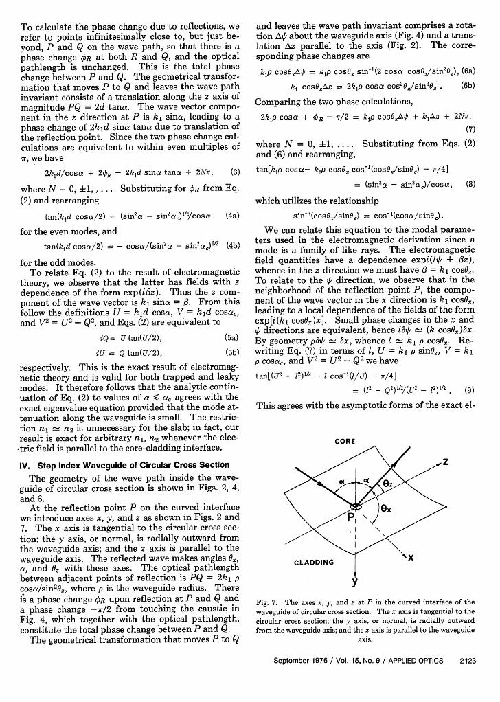
At the reflection point P on the curved interfacewe introduce axes x, y, and z as shown in Figs. 2 and7. The x axis is tangential to the circular cross sec-tion; the y axis, or normal, is radially outward fromthe waveguide axis; and the z axis is parallel to thewaveguide axis. The reflected wave makes angles Ox,a, and Oz with these axes. The optical pathlengthbetween adjacent points of reflection is PQ = 2k, pcosa/sin 2 0, where p is the waveguide radius. Thereis a phase change OR upon reflection at P and Q anda phase change -7r/2 from touching the caustic inFig. 4, which together with the optical pathlength,constitute the total phase change between P and Q.
The geometrical transformation that moves P to Q
and leaves the wave path invariant comprises a rota-tion A4 about the waveguide axis (Fig. 4) and a trans-lation Az parallel to the axis (Fig. 2). The corre-sponding phase changes are
kip cosO,Ao = kip cosO, sin-1(2 cosa cosSJsin 2 O,), (6a)
ki cosOAz - 2k1p cosa cos20Z/sin2 o . (6b)
Comparing the two phase calculations,
2kip cosa + R - 7T/2 = kp cosO.,A4 + kz + 2N9,
(7)
where N = 0 i1, .... Substituting from Eqs. (2)and (6) and rearranging,
tan[k1o cosa- kp cos6. cos'(cosO/sinz) - 7/4]
= (sin2a - sin2a)/cosa, (8)
which utilizes the relationship
sino1(cos09,/sin0 ) _ cos1 (cosu/sinz).
We can relate this equation to the modal parame-ters used in the electromagnetic derivation since amode is a family of like rays. The electromagneticfield quantities have a dependence expi(It + z),whence in the z direction we must have A = k, cosOz.To relate to the 1' direction, we observe that in theneighborhood of the reflection point P, the compo-nent of the wave vector in the x direction is k, cosO.,leading to a local dependence of the fields of the formexp[i(k1 cosOx)x]. Small phase changes in the x and,6 directions are equivalent, hence 4.'f (k cosOx)6x.By geometry pbip Ax, whence k, p cosOx. Re-writing Eq. (7) in terms of 1, U = k, p sinOfl, V = kp cosa,, and V2 = U2 - Q2 we have
tan[(U2 - 12)1/2 - cos t1(l/U) - 7/4]
= (12 - Q2 )1 2/(U 2 - 12)1/2 (9)
This agrees with the asymptotic forms of the exact ei-
CORE
y
Fig. 7. The axes x, y, and z at P in the curved interface of thewaveguide of circular cross section. The x axis is tangential to thecircular cross section; the y axis, or normal, is radially outwardfrom the waveguide axis; and the z axis is parallel to the waveguide
axis.
September 1976 / Vol. 15, No. 9 / APPLIED OPTICS 2123

V. Parabolic Index Waveguide of Circular CrossSection
With respect to cylindrical coordinates (r,o,z)based on the waveguide axis of symmetry, the refrac-tive index profile is
n2(r) = n - (n2 - n22)(r/p)2 (10)
where p is the core radius, n2 < n, and n2 a ni.To evaluate the phase change along the optical
path, Eq. (1), we must determine the equation for thewave path in the core from the vector equation
TUNNELLINGRAY
Fig. 8. The regions of incident ray angles at the reflection point Pof Fig. 2. Refracting rays are incident in the half-cone of semian-gle a,; trapped or totally internally reflected rays are incident inthe half-cone of semiangle r/2 - ac; and tunneling rays occupy the
two symmetric regions exterior to the two half-cones.
genvalue equation for trapped modes, tunnelingmodes,7 and weakly refracting modes7 within certainranges of these parameters.
The phenomenon of tunneling modes on the wave-guide of circular cross section has been reported pre-viously.7 Our approximate eigenvalue equation con-tains such modal solutions provided U >> 1, 1 >> 1, U-I >> U1 /3 1 - Q >> 1/3. When V >> 1, as is the casewith multimode waveguides of circular cross section,this region of parameter space contains virtually alltunneling mode solutions of the exact eigenvalueequation. To see this, we return to ray directionsand refer to Fig. 8, which depicts the regions of inci-dent angles at P corresponding to refraction, tunnel-ing or trapping (total internal reflection) of rays at P,as determined from the exact eigenvalue equation.Ray tunneling corresponds to the two symmetric re-gions about the meridional plane through P and ex-ternal to the two half-cones. Equation (9) predictsrays throughout these two regions provided a smallregion on either side of the meridional plane is ex-cluded, i.e., when 1 0O, !xx 7r/2.
Trapped modes correspond to Q pure imaginary.We find that Eq. (9) contains such solutions when U>> 1,1 >> 1, U - >> U1 /3 . If V >> 1, this region is thewhole of the trapped ray region of Fig. 8, i.e., thehalf-cone of semiangle r/2 - ac, with the exceptionof rays very close to meridional, 1 0, and close to a= ac.
As was the case with the slab, the analytic contin-uation of Eq. (9) to values of a < ac, i.e., Q > 1, agreeswith the asymptotic forms of the exact eigenvalueequation, provided that modal attenuation is small.In Fig. 8, this is a thin region around the edge of thehalf-cone a = ac of incident rays that are refracted.
The restriction n n2 is unnecessary, but itavoids the sensitivity of the result to the polarizationof the plane waves and greatly simplifies the resultsfor the waveguide of circular cross section.
d [r dr] = dn(r)i.WS- WnX~S- dr r
(11)
From the scalar components we have8
2r2 = (r,2 + r02) - (r 0
2 - r 2) cos(2z tanO,/r0 ), (12)
where r and r are the radii of the inner and outercaustics, respectively. The angle O is measured be-tween the tangent to the wave path and the z axis onthe inner caustic at P and Q as shown in Fig. 3. Sub-stituting Eq. (12) into Eq. (1) we find that the phasechange following the wave path between P and Q is
A = k7Tp[n2 + n2(ro) cos 20j/2(n 2- n2
2)1 /2, (13)
where k = 2r/X. There is the additional phasechange - since the wave path touches both theinner and outer caustics.
The geometrical transformation that moves P to Qconsists of a translation Az = rpn(ro) cosOz/(n, 2 -
n2 2)1 /2 parallel to the waveguide axis and a rotationAV = r about the axis in the azimuthal direction inFig. 3. The corresponding phase changes are
n(ro)k cosOA 2 = 7kpn 2(ro) cos 2O/(n, 2 - n22)1/2,
n(ro)kro sinOAOi = 7vkron(ro) sinO 2 .
(14a)
(14b)
Comparing the two phase calculations,
kp[n12 - n2(ro) cos 2 0/2(n 2 - n22)1/2- 1
= kron(ro) sinO, + 2N, (15)
where N = 0, i1 ....To relate Eq. (15) to the modal parameters, we
simply adapt the corresponding calculation for thestep-index waveguide and find
/0 = kn(r) cosO., = krn(r) coso., (16)
at the point r relative to local cartesian axes orientat-ed as in Fig. 7. When r = ro, Fig. 3 shows that O =Tr/2 - 0z, whence
/ = kn(ro) cosO2 , = kron(ro) sine2 . (17)
Substituting Eq. (17) into Eq. (15) we can write theeigenvalue equation as
U2 = 2V(2N + 1 + ), (18)
where U = p(n,2k2 - 2 )1/2 and V = kp(n, 2- n2
2 )1/2and N takes integral values such that U remains real.
In this form, the asymptotic eigenvalue equation isvalid for trapped rays. It does not hold for refracting
2124 APPLIED OPTICS / Vol. 15, No. 9 / September 1976

rays, which are lost into the cladding at r = p never toreturn into the core.
VI. Discussion
We have shown that our simple method of deriva-tion based on phase comparison leads to expressionsfor the eigenvalue equations of the slab waveguideand waveguide of circular cross section that containvirtually all trapped and weakly leaky tunneling andrefracting mode solutions of the exact eigenvalueequation when V >> 1. In the above discussion ofweakly leaky modes, the parameters U and Q arecomplex, and the corresponding mode attenuatesalong the waveguide.9 For very weak attenuation theimaginary parts of U and Q are small compared tothe real parts, and we are justified in taking U and Qapproximately real in the derivation of Eq. (8). Theattenuation coefficients corresponding to these imag-inary parts can be derived using the generalized Fres-nel's laws for reflection at a curved interface.' 0 "'
There are other approximate methods for derivingthe eigenvalue equation, e.g., the WKB method' 2 orits heuristic equivalent.'3 Our result agrees exactly
with the WKB procedure. Gloge's result is in errorby r, i.e., it does not include caustics. The causticcontribution is small when 1 is large.
References1. N. S. Kapany and J. J. Burke, Optical Waveguides (Academic,
New York, 1972).2. D. Marcuse, Theory of Dielectric Waveguides (Academic, New
York, 1973).3. Ref. 2, pp. 5-7.4. J. B. Keller and S. I. Rubinow, Ann. Phys. 9, 24 (1960).5. L. B. Felsen, Electron. Lett. 10, 95 (1974).6. K. G. Budden, Wave-Guide Mode Theory of Wave Propaga-
tion (Logos Press, London, 1961), p. 115.7. A. W. Snyder and J. D. Love, Opt. Commun. 12, 326 (1974).8. A. Cozannet and M. Treheux, Appl. Opt. 14, 1345 (1975).9. A. W. Snyder and D. J. Mitchell, J. Opt. Soc. Am. 64, 599
(1974).10. A. W. Snyder and J. D. Love, IEEE Trans. Microwave Theory
Tech. MTT-23, 134 (1975).11. A. W. Snyder and D. J. Mitchell, Optik 40, 438 (1974), see p.
443.12. A. Gedeon, Opt. Commun. 12, 329 (1974).13. D. Gloge, IEEE Trans. Microwave Theory Tech. MTT-23, 106
(1975).
Linwood Williams of Bendix Corporation.
W. Raymond Buchan of Itek Measurement SystemsDivision.
September 1976 / Vol. 15, No. 9 / APPLIED OPTICS 2125