optical, ethernet and multiservice tester · effi ciently assess fibre channel networks with...
TRANSCRIPT

SP
EC
SH
EE
T
OPTICALDynamic range up to either 36 or 39 dB
Test through high-port-count splitters (up to 1×128)
Combined singlemode/multimode wavelengths
Event dead zone as low as 0.8 meters
iOLM-ready: one-touch multiple acquisitions, with clear go/no-go results presented in a straightforward visual format
Integrated tool combines a visual fault locator, inspection probe, broadband power meter and a CW source mode
MULTISERVICE SONET/SDH, OTN and Ethernet interfaces up to 11.3 Gbit/s
Packet synchronization turn-up and troubleshooting (SyncE/1588 PTP)
FTTA validation (CPRI and OBSAI up to 3.1 Gbit/s via BER testing)
Effi ciently assess Fibre Channel networks with best-in-class coverage via 1×, 2×, 4×, 8× and 10× interfaces
OTN testing (as per ITU-T G.709)
Ethernet service activation with bidirectional EtherSAM (ITU-T Y.1564) and RFC 2544 test suites, multistream traffi c generation, Through mode and BER testing
Carrier Ethernet OAM testing covering the MEF, Y.1731 and 802.1ag standards
Full line-rate packet capture and advanced fi ltering from 10M to 10G
Layer-2 transparency testing with predefi ned confi gurations
True wire-speed, stateful TCP throughput test based on RFC 6349 forundisputable SLA enforcement of Ethernet services
An all-in-ONE Ethernet/optical solution for field technicians installing, testing and troubleshooting FTTx, fronthaul, backhaul, small cell, DAS, remote radio head and data center networks, in addition to OTN, SONET/SDH, Fibre Channel, GigE and 10 GigE, CPRI/OBSAI and SyncE/1588 PTP services, with the added support of OTDR and iOLM capabilities.
FTB-700G SeriesOPTICAL, ETHERNET AND MULTISERVICE TESTER
Feature(s) of this product is/are protected by one or more of patent appl. US 2012/0307666 A1 and equivalents in other countries.
Data Post-Processing SoftwareFastReporter 2
COMPLEMENTARY PRODUCTS
PlatformFTB-1
Fiber Inspection ProbeFIP-400B

FTB-700G Series
THE ULTRA-PORTABLE CHOICE FOR MULTISERVICE TESTINGThe ongoing transition towards a converged network infrastructure for optical, SONET/SDH, OTN, Fibre Channel and packet-based Ethernet services requires a test tool that can cover a wide range of interfaces and rates without sacrificing portability, speed or cost. Leveraging the powerful FTB-1 handheld platform, the FTB-700G Series streamlines processes and empowers field technicians to efficiently test and validate optical networks, SONET/SDH, OTN, Fibre Channel and Ethernet circuits.
THE BEST FROM OPTICAL, ETHERNET AND MULTI-TEST FEATURES
3 4
79101213 11 8
1 2
65
1 10M-1G Electrical Ports
2 100M-1G Optical Ports
3 10G Optical Port
4 External Clock Reference
5 OTDR Port (Multimode)
6 OTDR Port (Singlemode)
7 Power
8 Fiber Inspection Probe
9 Headset
10 Ethernet Management Port
11 USB Ports
12 Visual Fault Locator
13 Power Meter
OPTICALFIBER CONNECTOR INSPECTION AND CERTIFICATION - THE ESSENTIAL FIRST STEP
Taking the time to properly inspect a fiber-optic cable can prevent a slew of problems down the line–saving you time, money and headaches.
FIP-430B | The First Fully Automated Fiber Inspection Probe for the FieldHousing a unique automatic focus adjustment system, the FIP-430B automates each operation in the connector endface inspection sequence, transforming this critical process into one quick and easy step, which can be performed by technicians of all skill levels.
FEATURES Basic
FIP-410BSemi-Automated
FIP-420BFully-Automated
FIP-430B
Three magnification levels √ √ √
Image capture √ √ √
Five-megapixel CMOS capturing device √ √ √
Automatic fiber image-centering function X √ √
Automatic focus function X X √
On-board pass/fail analysis X √ √
Pass/fail LED indicator X √ √
3 models to fit your budget:
Read the FIP-400B specifi cation sheet or visit www.EXFO.com/keepthefocus for more information.
57%shorter test time b
100%Automated a
1-step process a
Notes
a. Model FIP-430B only.
b. Data sourced from EXFO`s case study, with calculation based on typical analysis time.
FTB-700G Series
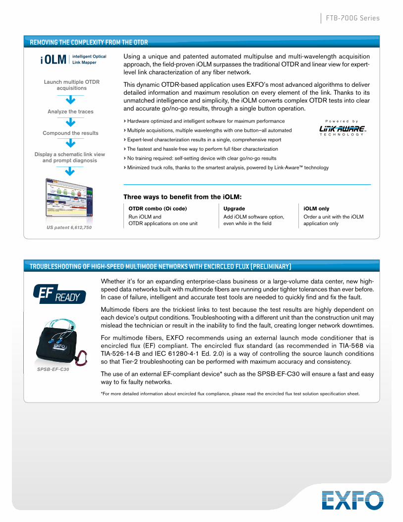
REMOVING THE COMPLEXITY FROM THE OTDR
Using a unique and patented automated multipulse and multi-wavelength acquisition approach, the field-proven iOLM surpasses the traditional OTDR and linear view for expert-level link characterization of any fiber network.
This dynamic OTDR-based application uses EXFO’s most advanced algorithms to deliver detailed information and maximum resolution on every element of the link. Thanks to its unmatched intelligence and simplicity, the iOLM converts complex OTDR tests into clear and accurate go/no-go results, through a single button operation.
› Hardware optimized and intelligent software for maximum performance
› Multiple acquisitions, multiple wavelengths with one button—all automated
› Expert-level characterization results in a single, comprehensive report
› The fastest and hassle-free way to perform full fi ber characterization
› No training required: self-setting device with clear go/no-go results
› Minimized truck rolls, thanks to the smartest analysis, powered by Link-Aware™ technology
Three ways to benefit from the iOLM:
P o w e r e d b y
T E C H N O L O G Y
US patent 6,612,750
Launch multiple OTDR acquisitions
Analyze the traces
Compound the results
Display a schematic link view and prompt diagnosis
OTDR combo (Oi code)
Run iOLM and OTDR applications on one unit
Upgrade
Add iOLM software option, even while in the field
iOLM only
Order a unit with the iOLM application only
TROUBLESHOOTING OF HIGH-SPEED MULTIMODE NETWORKS WITH ENCIRCLED FLUX (PRELIMINARY)
Whether it’s for an expanding enterprise-class business or a large-volume data center, new high-speed data networks built with multimode fibers are running under tighter tolerances than ever before. In case of failure, intelligent and accurate test tools are needed to quickly find and fix the fault.
Multimode fibers are the trickiest links to test because the test results are highly dependent on each device’s output conditions. Troubleshooting with a different unit than the construction unit may mislead the technician or result in the inability to find the fault, creating longer network downtimes.
For multimode fibers, EXFO recommends using an external launch mode conditioner that is encircled flux (EF) compliant. The encircled flux standard (as recommended in TIA-568 via TIA-526-14-B and IEC 61280-4-1 Ed. 2.0) is a way of controlling the source launch conditions so that Tier-2 troubleshooting can be performed with maximum accuracy and consistency.
The use of an external EF-compliant device* such as the SPSB-EF-C30 will ensure a fast and easy way to fix faulty networks.
* For more detailed information about encircled flux compliance, please read the encircled flux test solution specification sheet.
SPSB-EF-C30

FTB-700G Series
SONET/SDH, OTN, FIBRE CHANNEL AND ETHERNET AT UP TO 11.3 GBIT/S
The FTB-700G Series is the perfect solution for multiservice testing up to 11.3 Gbit/s.
› RJ-45 port for electrical 10/100/1000M Ethernet
› SFP port for OC-1/3/12/48 or STM-0/1/4/16, OTU1 and Fibre Channel 1×, 2×, 4× or 100/1000M Ethernet
› One SFP port at 2.5 and 3.1 Gbits/s
› SFP+ port for OC-192, STM-64, 10 GigE LAN/WAN or Fibre Channel 8×, 10×, OTU2, OTU1e/2e and OTU1f/2f
› SONET/SDH and OTN BER testing with configurable threshold settings
› Coupled, Decoupled and Through mode testing
› Error and alarm insertion and monitoring
› Overhead monitoring and manipulation
› High-order and low-order mappings
› Tandem connection monitoring (TCM)
› Pointer manipulation, including pointer sequence testing as per Telcordia GR-253, ANSI T1.105-03 and ITU G.783
› Performance monitoring as per G.821, G.826, G.828, G.829, M.2100, M.2101
› Frequency analysis and offset generation
› Automatic protection switching
› Service-disruption time measurements
› Round-trip delay measurements
› External clock sync support
› 10Base-T to 10 GigE testing
› EtherSAM (ITU-T Y.1564) (bidirectional)
› RFC 2544 (bidirectional)
› Traffic generation and monitoring
› Through mode
› Dual-port testing
› Intelligent autodiscovery
› MPLS
› VLANs, including E-VLAN, S-VLAN, C-VLAN
› 1588 PTP and SyncE
› TCP Throughput
› Full line-rate packet capture and advanced filtering from 10M to 10G
› Carrier Ethernet OAM (MEF, 802.1ag, Y.1731)
› IPv6 testing
› Ping/Traceroute
› Cable testing
› Dual Test Set mode
› Smart loopback
› Fibre Channel 1×, 2×, 4×, 8×, 10×
› FTTA BERT
MULTISERVICEPOWERFUL AND FASTThe FTB-700G Series is a fully integrated optical, SONET/SDH, OTN, Fibre Channel and Ethernet handheld tester. It offers the industry’s largest touchscreen and unprecedented configuration simplicity via a hybrid touchscreen/keypad navigation interface. Platform connectivity is abundant via 3G, Wi-Fi, Bluetooth, Gigabit Ethernet or USB ports, making it accessible in any environment.
What you need for any SONET/SDH, OTN, Fibre Channel or Ethernet application › Installation, commissioning and maintenance of access and
metro networks
› Turn-up of SONET/SDH circuits
› Performance assessment of Carrier Ethernet services
› Validation of OTN networks and services
› Installation, activation and maintenance of metro Ethernet networks
› Deployment of active Ethernet (point-to-point) access services
› Installation and activation of Fibre Channel networks
› Testing and troubleshooting
› In-service troubleshooting of live traffi c
› Performance monitoring of SONET/SDH and OTN circuits
› Round-trip delay assessment of transport circuits
› BER testing up to 11.3 Gbit/s
› FTTA validation (CPRI and OBSAI) at up to 3.1 Gbit/s via BER testing

FTB-700G Series
REVAMPED SETUP PROCEDURES The new Test Configurator not only allows tests to be easily setup, it provides critical test info immediately after the actual setup stage. In the screenshot to the right, the RFC 2544 test was selected with Throughput and Back-To-Back tests enabled (Frame Loss and Latency are disabled). The green arrow pointing up confirms that the link is up. The destination IP address is resolved and the test is ready to be executed. The Test Configurator covers all stages of testing: setup, review and execution.
The control panel has icons to access the most important testing elements, buttons for the Setup, Results and Functions screens, as well as a clear pass/fail indicator. Field techs have the assurance that their testing time is optimized.
The new Test Configurator not only allows tests to be easily setup, it provides critical test info immediately after the actual setup stage. In the screenshot to the right, the RFC 2544 test was selected with Throughput and Back-To-Back tests enabled (Frame Loss and Latency are disabled). The green arrow pointing up confirms that the link is up. The destination IP address is resolved and the test is ready to be executed.
The control panel has icons to access the most important testing elements, buttons for the Setup, Results and Functions screens, as well as a clear pass/fail indicator.
MULTISERVICE
Setting a New GUI Standard: Unprecedented Simplicity in Configuration Setup and Navigation The FTB-700G Series intelligent situational-configuration setup feature guides technicians through complete, accurate testing processes (suggestion prompts, help guides, etc.). It reduces navigation by combining associated testing functions on a single screen, and offers intelligent autodiscovery that allows a single technician to perform end-to-end testing.
Failed Test
Exact Alarm Description
Yellow Indicator of Previous Event
All OKStep-By-StepTesting Status
Dedicated Quick-Action Buttons› Remote discovery to fi nd
all other EXFO units
› Laser on/off
› Test reset to clear results and statistics while running a test
› Report generation
› Save or load test confi gurations
› Quick error injection
› Enable second Ethernet loopback port
Assorted Notifications› Clear indication of link status
for single or dual ports
› Negotiated speed display for single or dual ports
› Power status available at all times for single or dual ports
› Pass/fail indication at all times
› Pattern and clock synchronization
› Frequency offset with valid-range color indicator
› Overhead overwrite indicator
› Error/alarm injection
› Alarm hierarchy pinpointing the root cause (when possible)
Streamlined Navigation› Remote discovery button available
at all times; no reason to leave your current location to scan for a remote unit
› Testing status can be maximized to fi ll the entire screen by simply clicking on the alarm status button;
whether the unit is in your hand or across the room, test results can be easily determined with a simple glance at the display screen
› RFC 2544 results and graphs are also maximized in a single page; no need to navigate through multiple screens to view individual RFC subtest results
› Simplifi ed test structure defi nition using task-based test-application selection, signal confi guration, front-end and smart timeslot selection
› Centralized functions: error/alarm management, performance monitoring and overhead manipulation/monitoring

FTB-700G Series
Key OTN SONET/SDH Features
Simplified BER Testing
The FTB-700G Series provides the ability to preconfigure bit-error-rate (BER) thresholds that are user-defined prior to running the test. This allows for a simple pass/fail verdict at the conclusion of the test, leaving no room for misinterpretation of the test results.
Through Mode
This mode is required for in-service monitoring of the network. The FTB-700G Series can be inserted in-line on a specific link to monitor and analyze the errors and alarms in a non-intrusive manner.
Simplified Error Injection
This FTB-700G Series feature enables the user to inject errors with a single click from any screen, allowing technicians to ensure circuit continuity prior to starting a test. Furthermore, the error injection functionality can be preprogrammed for any given type of error, and not just for bit errors.
Complete Overhead Monitoring
The FTB-700G Series offers access to all SONET/SDH or OTN overhead (OH) bytes. Furthermore, by selecting any given OH byte, the user can retrieve additional detailed information about that byte without having to switch pages.
MULTISERVICEDecoupled Mode
The Decoupled mode enables the user to independently configure the Tx and Rx ports of the FTB-700G Series module. This makes it possible to test the mapping and demapping functionality of a network element or at cross-connect points in the network.

FTB-700G Series
MULTISERVICE
Key Ethernet Features
Intelligent Network Discovery Mode
Using the FTB-700G Series test set, you can single-handedly scan the network and connect to any available EXFO datacom remote tester. Simply select the unit to be tested and choose whether you want traffic to be looped back via Smart Loopback or Dual Test Set for simultaneous bidirectional EtherSAM and RFC 2544 results. No more need for an additional technician at the far end to relay critical information—these modules take care of it all.
Smart Loopback Flexibility
The Smart Loopback functionality has been enhanced to offer five distinct loopback modes. Whether you are looking to pinpoint loopback traffic from a UDP or TCP layer, or all the way down to a completely promiscuous mode (Transparent Loopback mode), the FTB-700G Series has the flexibility to adjust for all unique loopback situations.
Dual-Port and Through Mode Testing
The NetBlazer series is equipped for both Through mode or dual-port testing. Through mode allows traffic to pass through either of the module’s two electrical or optical ports for in-service troubleshooting of live traffic between the carrier/service provider network and the customer’s network. This allows technicians to access circuits under test without the need for a splitter. With dual-port testing, the technician can use a single module to launch the test and perform the loopback. With two modules, the dual-port feature also enables users to run two simultaneous tests to maximize time and efficiency.
VLAN/MPLS
Today’s networks are expected to deliver high performance. To meet such high expectations, service providers must rely on various mechanisms, such as Ethernet tagging, encapsulation and labeling. Thanks to these additions, service providers can enhance security, scalability, reliability and performance. The FTB-700G Series module supports virtual local area network (VLAN) tags, Q-in-Q VLAN tags and multiprotocol label switching (MPLS).switching (MPLS).

FTB-700G Series
MULTISERVICEETHERSAM: THE NEW STANDARD IN ETHERNET TESTINGRFC 2544 used to be the most widespread Ethernet testing methodology. However, it was designed for network-device testing in the lab, not for service testing in the field. ITU-T Y.1564 is the new standard for turning up and troubleshooting Carrier Ethernet services. It has a number of advantages over RFC 2544, including validation of critical SLA criteria, such as packet jitter and QoS measurements. This methodology is also significantly faster, therefore saving time and resources while optimizing QoS.
EXFO’s EtherSAM test suite—based on the ITU-T Y.1564 Ethernet service activation methodology—provides comprehensive field testing for mobile backhaul and commercial services.
Contrary to other methodologies, EtherSAM supports new multiservice offerings. It can simulate all types of services that will run on the network and simultaneously qualify all key SLA parameters for each of these services. Moreover, it validates the QoS mechanisms provisioned in the network to prioritize the different service types, resulting in better troubleshooting, more accurate validation and much faster deployment. EtherSAM is comprised of two phases, the service configuration test and the service performance test.
Service Configuration TestThe service configuration test consists of sequentially testing each service in order to validate that it is properly provisioned, and that all specific KPI or SLA parameters are met. A ramp test and a burst test are performed to verify the committed information rate (CIR), excess information rate (EIR), committed burst size (CBS) and excess burst size (EBS).
Service Performance TestOnce the configuration of each individual service is validated, the service performance test simultaneously validates the quality of all the services over time.
Ramp Test Burst Test

FTB-700G Series
MULTISERVICE
EtherSAM Bidirectional ResultsEXFO’s EtherSAM approach proves even more powerful, as it executes the complete ITU-T Y.1564 test with bidirectional measurements. Key SLA parameters are measured independently in each test direction, thus providing 100% first-time-right service activation—the highest level of confidence in service testing.
FTTA TESTINGThe times are constantly changing and the telecommunications industry is rapidly evolving to keep pace. This is especially true when it comes to mobile network operators (MNOs) and the delivery of their services. Bandwidth-hogging applications like high-definition video, media-rich content and interactive mobile applications are being introduced at an ever-increasing rate. The wireless infrastructure has to be modernized to keep up with this continuous, high-bandwidth growth and to minimize latency. To meet these expectations, MNOs are now switching their infrastructures from legacy “copper to the antenna” to fiber-to-the-antenna (FTTA). With the introduction of FTTA, MNOs can offer better performance with lower base-station costs. One key component of evolving to FTTA requires the addition of either the common public radio interface (CPRI) or the open base station architecture initiative (OBSAI).
Incorporating either CPRI or OBSAI, the actual base stations can be located in much less challenging locations, where size, climate and availability of power are much more easily managed. In addition, wireless network providers can maximize the base-station output by having multiple antennas per offsite base station.
With the FTB-700G Series of modules, field technicians can perform FTTA tests (CPRI or OBSAI). Whether the need is for 2.5 or 3.1 Gbit/s, the FTB-700G Series modules can perform a BER test that validates the fiber from the remote base station all the way to the remote radio head.

FTB-700G Series
Carrier Ethernet OAMEver since the introduction of metro Ethernet networks, there has been a need to ensure “five nines” level of availability, reliability and 50-millisecond recovery times from failures. Just as PDH, TDM and SONET/SDH, OAM has become a crucial network component that has enabled the same quality for carrier-class Ethernet.
The NetBlazer series offers a new application that validates the mechanics of the service operation, administration and maintenance (S-OAM) tools, which covers Y.1731, 802.1ag and MEF modes. The features of this application include continuity check generation and monitoring, loopback testing, frame loss, synthetic loss and frame delay. There is also an S-OAM link trace and responder.
Packet CaptureThe capturing power of EXFO’s NetBlazer Series extends far beyond basic capabilities. The NetBlazer series adds extra features and functionalities to boost test cycle efficiency and provides more value. Its packet capture tool offers comprehensive filtering, triggering and truncation methods to target specific traffic and quickly pinpoint issues in the lab and in the field.
Advanced Traffic FilteringIn some cases, troubleshooting only concerns a particular traffic flow. The advanced traffic-filtering capability of the NetBlazer series allows you to restrict traffic by using up to four matching fields and operands (and, or, not). A complete set of triggers is available, such as MAC, IP and TCP/UDP fields, as well as VLAN, MPLS fields.
FTB-700G Series
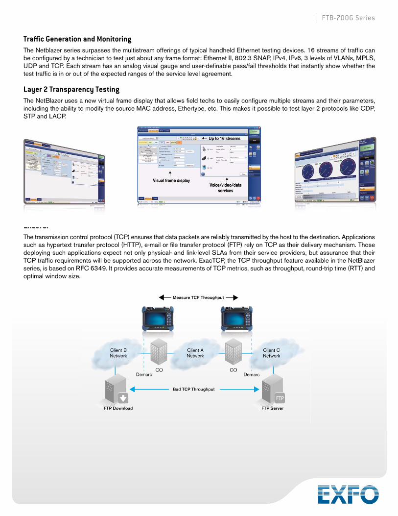
Traffic Generation and MonitoringThe Netblazer series surpasses the multistream offerings of typical handheld Ethernet testing devices. 16 streams of traffic can be configured by a technician to test just about any frame format: Ethernet II, 802.3 SNAP, IPv4, IPv6, 3 levels of VLANs, MPLS, UDP and TCP. Each stream has an analog visual gauge and user-definable pass/fail thresholds that instantly show whether the test traffic is in or out of the expected ranges of the service level agreement.
Layer 2 Transparency TestingThe NetBlazer uses a new virtual frame display that allows field techs to easily configure multiple streams and their parameters, including the ability to modify the source MAC address, Ethertype, etc. This makes it possible to test layer 2 protocols like CDP, STP and LACP.
EXacTCPThe transmission control protocol (TCP) ensures that data packets are reliably transmitted by the host to the destination. Applications such as hypertext transfer protocol (HTTP), e-mail or file transfer protocol (FTP) rely on TCP as their delivery mechanism. Those deploying such applications expect not only physical- and link-level SLAs from their service providers, but assurance that their TCP traffic requirements will be supported across the network. ExacTCP, the TCP throughput feature available in the NetBlazer series, is based on RFC 6349. It provides accurate measurements of TCP metrics, such as throughput, round-trip time (RTT) and optimal window size.
EXacTCP

FTB-700G Series
MULTISERVICEEFFICIENTLY ASSESSING PERFORMANCEOF FIBRE CHANNEL SERVICESThe FTB-700G Series modules provide comprehensive testing capabilities for Fibre Channel network deployments, supportingmultiple Fibre Channel interfaces.
APPLICATIONSSince most storage area networks (SANs) cover large distances and because Fibre Channel has stringent performance requirements, it is imperative to test at each phase of network deployment to ensure appropriate service levels. EXFO’s FTB-700G Series modules provide full wire-speed traffic generation at the FC-2 layer, which allows BER testing for link integrity measurements. The FTB-700G Series also supports latency, buffer-to-buffer credit measurements for optimization, as well as login capabilities.
LatencyTransmission of frames in a network is not instantaneous, and is subject to multiple delays caused by the propagation delay in the fiber and by the processing time inside each piece of network equipment. Latency is the total accumulation of delays between two end-points. Some applications, such as VoIP, video, and storage area networks, are very sensitive to excess latency.
It is therefore critical for service providers to properly characterize network latency when offering Fibre Channel services. The FTB-700G Series modules estimate buffer-to-buffer credit value requirements from the performed latency measurement.
Buffer-to-Buffer Credit EstimationTo regulate traffic flow and congestion, Fibre Channel ports use “buffers” to temporarily store frames. The number of frames a port can store is referred to as a “buffer credit.” Each time a frame is received by a port, an acknowledgement frame is sent. The buffer-to-buffer credit threshold refers to the amount of frames a port can transmit without receiving a single acknowledgement.
This is a crucial configuration parameter for optimal network performance. Usually, network administrators calculate the value by taking the traveled distance and the data rate into consideration; however, since latency issues are not considered, poor accuracy is to be expected. The FTB-700G Series modules are capable of estimating buffer credit values with respect to latency by calculating the distance according to the round-trip latency time. This value can then be used by network administrators to optimize the network configuration.
Login TestingMost new-generation transport devices (xWDM or SONET/SDH mux) supporting Fibre Channel are no longer fully transparent; they also have increased built-in intelligence, acting more as Fibre Channel switches. With switch fabric login ability, the FTB-700G Series modules support connections to a remote location through a fabric or semitransparent network.
The login process not only permits the unit to connect through a fabric, but it also exchanges some of the basic port characteristics (such as buffer-to-buffer credit and class of service) in order to efficiently transport the traffic through the network.
The login feature allows automatic detection of port/fabric login, login status (successful login, in progress, failure and logout) and response to remote buffer-to-buffer advertised credit.
COMPLETE SUITE OF FIBRE CHANNEL INTERFACESInterface Signal Rate (Gbit/s) Data Rate (MB/s)
1× 1.0 100
2× 2.1 200
4× 4.2 400
8× 8.5 800
10× 10.5 1200
Thanks to end-to-end network testing capabilities, EXFO’s FTB-700G Series enables fast deployment and configuration of Fibre Channel networks. Communication between the transport network, interconnection devices and end nodes can be validated with features such as BER testing, latency measurement, buffer-to-buffer credit estimation and port login capabilities.

FTB-700G Series
EXPERT TEST TOOLS ON THE FTB-1 PLATFORMEXpert Test Tools is a series of platform-based software testing tools that enhance the value of the FTB-1 platform, providing additional testing capabilities without the need for additional modules or units.
EXpert TEST TOOLS
The EXpert VoIP Tools generate a voice-over-IP call directly from the test platform to validate performance during service turn-up and troubleshooting.
• Supports a wide range of signaling protocols, including SIP, SCCP, H.248/Megaco and H.323
• Supports MOS and R-factor quality metrics
• Simplifies testing with configurable pass/fail thresholds and RTP metrics
The EXpert IP Tools integrate six commonly used datacom test tools into one platform-based application to ensure that field technicians are prepared for a wide range of testing needs.
• Rapidly perform debugging sequences with VLAN scan and LAN discovery
• Validate end-to-end ping and traceroute
• Verify FTP performance and HTTP availability
This powerful IPTV quality assessment solution enables set-top-box emulation and passive monitoring of IPTV streams, allowing quick and easy pass/fail verification of IPTV installations.
• Real-time video preview
• Analyzes up to 10 video streams
• Comprehensive QoS and QoE metrics, including MOS score
EXFO Connect
AUTOMATED ASSET MANAGEMENT. PUSH TEST DATA IN THE CLOUD. GET CONNECTED.EXFO Connect pushes and stores test equipment and test data content automatically in the cloud, allowing you to streamline test operation from build-out to maintenance.
MULTISERVICE

FTB-700G Series
OPTICAL TECHNICAL SPECIFICATIONS a
Notes
a. All specifications valid at 23 °C ± 2 °C with an FC/PC connector, unless otherwise specified; APC connector for FTB-720G and FTB-730G singlemode models.
b. Typical.
c. Typical dynamic range with longest pulse and three-minute averaging at SNR = 1.
d. Typical dead zone for reflectance below –45 dB, using a 5 ns pulse.
e. Does not include uncertainty due to fiber index.
f. Typical output power is given at 1550 nm.
g. Non-reflective FUT, non-reflective splitter, 13 dB loss, 50 ns pulse, typical value.
TECHNICAL SPECIFICATIONS FTB-720G FTB-730G OTDRWavelength (nm) b 850 ± 20, 1300 ± 20, 1310 ± 20, 1550 ± 20 1310 ± 20/1550 ± 20
Dynamic range (dB) c, d 27, 26, 36 39/37
Event dead zone (m) e 0.8 0.8
Attenuation dead zone (m) e 4, 4.5, 5, 5, 5 4/4.5
Distance range (km) Multimode: 0.1, 0.3, 0.5, 1.3, 2.5, 5, 10, 20, 40Singlemode: 1.25, 2.5, 5, 10, 20, 40, 80, 160, 260 1.25, 2.5, 5, 10, 20, 40, 80, 160, 260, 400
Pulse width (ns) Multimode: 5, 10, 30, 50, 100, 275, 500, 1000Singlemode: 5, 10, 30, 50, 100, 275, 500, 1000,
2500, 10 000, 20 0005, 10, 30, 50, 100, 275, 500, 1000, 2500, 10 000, 20 000
Launch conditions f Encircled Flux (EF) compliant i
Linearity (dB/dB) b ±0.03 ±0.03
Loss threshold (dB) 0.01 0.01
Loss resolution (dB) 0.001 0.001
Sampling resolution (m) Multimode: 0.04 to 2.5Singlemode: 0.04 to 5 0.04 to 5
Sampling points Up to 256 000 Up to 256 000
Distance uncertainty (m) g ±(0.75 + 0.0025 % x distance + sampling resolution) ±(0.75 + 0.0025 % x distance + sampling resolution)
Measurement time User-defined (60 min. maximum) User-defined (60 min. maximum)
Typical real-time refresh (Hz) 3 4
Stable source output power (dBm) h –3 (1300 nm), –7 (1550 nm) –2.5
Reflectance ±2

FTB-700G Series
SFP ETHERNET OPTICAL INTERFACESTwo ports: 100M and GigE
Available wavelengths (nm) 850, 1310 and 1550
Model FTB-85910 FTB-85911 FTB-8590 FTB-8190 FTB-8192 FTB-8596 FTB-8597
Transceiver type 100 Base-FX 100 Base-LX 1000 Base-SX 1000 Base-LX 1000 Base-ZX 1000 Base-BX10-D 1000 Base-BX10-U
Wavelength (nm) 1310 1310 850 1310 1550 Tx: 1490Rx: 1310
Tx: 1310Rx: 1490
Tx level (dBm) –20 to –15 –15 to –8 –9 to –3 –9.5 to –3 0 to 5 –9.5 to –3 –9.5 to –3
Rx level sensitivity (dBm) –31 –28 –20 –22 –22 –20 –20
Maximum reach 2 km 15 km 550 m 10 km 80 km 10 km 10 km
Transmission bit rate (Gbit/s) 0.125 0.125 1.25 1.25 1.25 1.25 1.25
Reception bit rate (Gbit/s) 0.125 0.125 1.25 1.25 1.25 1.25 1.25
Tx operational wavelength range (nm) 1280 to 1380 1261 to 1360 830 to 860 1270 to 1360 1540 to 1570 1480 to 1500 1260 to 1360
Measurement accuracy (uncertainty)Frequency (ppm)Optical power (dB)
±4.6±2
±4.6±2
±4.6±2
±4.6±2
±4.6±2
±4.6±2
±4.6±2
Maximum Rx before damage (dBm) a 3 3 6 6 6 6 6
Jitter compliance ANSI ×3.166 IEEE 802.3 IEEE 802.3 IEEE 802.3 IEEE 802.3ah IEEE 802.3ah
Ethernet classification ANSI ×3.166 IEEE 802.3 IEEE 802.3 IEEE 802.3 IEEE 802.3ah IEEE 802.3ah
Laser type LED FP VCSEL FP DFB DFB FP
Laser product Class 1 Class 1 Class 1 Class 1 Class 1 Class 1 Class 1
Connector b LC LC LC LC LC LC LC
MULTISERVICE SPECIFICATIONS
SFP c SONET/SDH AND OTN OPTICAL INTERFACESTransceiver type OC-3/STM-1 OC-12/STM-4 OC-48/STM-16/OTU1
Reach and wavelength 15 km; 1310 nm 40 km; 1310 nm 40 km; 1550 nm 80 km; 1550 nm 15 km; 1310 nm 40 km; 1310 nm 40 km; 1550 nm 80 km; 1550 nm 15 km; 1310 nm 40 km; 1310 nm 40 km; 1550 nm 80 km; 1550 nm
Model FTB-8190 FTB-8191 FTB-8193 FTB-8192 FTB-8190 FTB-8191 FTB-8193 FTB-8192 FTB-8190 FTB-8191 FTB-8193 FTB-8192
Tx level (dBm) –5 to 0 –2 to 3 –5 to 0 –2 to 3 –5 to 0 –2 to 3 –5 to 0 –2 to 3 –5 to 0 –2 to 3 –5 to 0 –2 to 3
Rx operating range (dBm) –23 to –10 –30 to –15 –23 to –10 –30 to –15 –22 to 0 –27 to –9 –22 to 0 –29 to –9 –18 to 0 –27 to –9 –18 to 0 –28 to –9
Transmit bit rate 155.52 Mbit/s ± 4.6 ppm 622.08 Mbit/s ± 4.6 ppm 2.48832 Gbit/s ± 4.6 ppm2.66606 Gbit/s ± 4.6 ppm
Frequency offset generation (ppm) ±50 ±50 ±50
Receive bit rate 155.52 Mbit/s ± 100 ppm 622.08 Mbit/s ± 100 ppm 2.48832 Gbit/s ± 100 ppm2.66606 Gbit/s ± 100 ppm (OTU1)
Operational wavelength range (nm)
1261 to 1360
1263 to 1360
1430 to 1580
1480 to 1580
1270 to 1360
1280 to 1335
1430 to 1580
1480 to 1580
1260 to 1360
1280 to 1335
1430 to 1580
1500 to 1580
Spectral width 1 nm (–20 dB) 1 nm (–20 dB) 1 nm (–20 dB)
Measurement accuracy (uncertainty)
Frequency (ppm)Optical power (dB)
±4.6±2
±4.6±2
±4.6±2
Maximum Rx before damage (dBm) a 3 3 3
Jitter compliance GR-253 (SONET)G.958 (SDH)
GR-253 (SONET)G.958 (SDH)
GR-253 (SONET)G.958 (SDH)G.8251 (OTN)
Line coding NRZ NRZ NRZ
Laser product Class 1 Class 1 Class 1
Connector b LC LC LC
Notes
a. To avoid exceeding the maximum receiver power level before damage, an attenuator must be used.
b. External adaptors can be used for other types of connectors.
c. SFP compliance: The FTB-700G Series selected SFP shall meet the requirements stated in the “Small Form-Factor Pluggable (SFP) Transceiver Multisource Agreement (MSA).” The FTB-700G Series selected SFP shall meet the requirements stated in the “Specification for Diagnostic Monitoring Interface for Optical Xcvrs.”

FTB-700G Series
SFP+ c 10G SONET/SDH AND OTN OPTICAL INTERFACESTransceiver type OC-192/STM-64/OTU2 OC-192/STM-64/OTU2 OC-192/STM-64/OTU2
Wavelength (nm) 1310 1550 1550
Model FTB-8693 FTB-8694 FTB-8695
Tx level (dBm) –6 to –1 –1 to 2 0 to 4
Rx level sensitivity (dBm) –11 to 0.5 –14 to –1 –24 to –7
Maximum reach 10 km 40 km 80 km
Transmission bit rate (Gbit/s)
9.9532 ± 4.6 ppm10.7092 ± 4.6 ppm (OTU2)11.0491 ± 4.6 ppm (OTU1e)11.0957 ± 4.6 ppm (OTU2e)11.2701 ± 4.6 ppm (OTU1f)11.3176 ± 4.6 ppm (OTU2f)
9.9532 ± 4.6 ppm10.7092 ± 4.6 ppm (OTU2)11.0491 ± 4.6 ppm (OTU1e)11.0957 ± 4.6 ppm (OTU2e)11.2701 ± 4.6 ppm (OTU1f)11.3176 ± 4.6 ppm (OTU2f)
9.9532 ± 4.6 ppm10.7092 ± 4.6 ppm (OTU2)11.0491 ± 4.6 ppm (OTU1e)11.0957 ± 4.6 ppm (OTU2e)11.2701 ± 4.6 ppm (OTU1f)11.3176 ± 4.6 ppm (OTU2f)
Frequency offset generation (ppm) ±50 ±50 ±50
Reception bit rate (Gbit/s)
9.9532 ± 100 ppm10.7092 ± 100 ppm (OTU2)11.0491 ± 120 ppm (OTU1e)11.0957 ± 120 ppm (OTU2e)11.2701 ± 120 ppm (OTU1f)11.3176 ± 120 ppm (OTU2f)
9.9532 ± 100 ppm10.7092 ± 100 ppm (OTU2)11.0491 ± 120 ppm (OTU1e)11.0957 ± 120 ppm (OTU2e)11.2701 ± 120 ppm (OTU1f)11.3176 ± 120 ppm (OTU2f)
9.9532 ± 100 ppm10.7092 ± 100 ppm (OTU2)11.0491 ± 120 ppm (OTU1e)11.0957 ± 120 ppm (OTU2e)11.2701 ± 120 ppm (OTU1f)11.3176 ± 120 ppm (OTU2f)
Tx operational wavelength range (nm) 1260 to 1355 1530 to 1565 1530 to 1565
Measurement accuracy (uncertainty) Frequency (ppm) Optical power (dB)
±4.6±2
±4.6±2
±4.6±2
Maximum Rx before damage (dBm) a 5 5 3
Jitter complianceGR-253 (SONET)
G.825 (SDH)G.8251 (OTN)
GR-253 (SONET)G.825 (SDH)G.8251 (OTN)
GR-253 (SONET)G.825 (SDH)G.8251 (OTN)
Laser product Class 1 Class 1 Class 1
Connector b LC LC LC
SFP+ ETHERNET OPTICAL INTERFACESTransceiver type 10G Base-SR/SW 10G Base-LR/LW 10G Base-ER/EW
Wavelength (nm) 850 1310 1550
Model FTB-8690 FTB-8691 FTB-8692
Tx level (dBm) –5 to –1 –8 to 0.5 –4.7 to 4.0
Rx level sensitivity (dBm) –11.1 –12.6 –14.1
Maximum reach 300 m 10 km 40 km
Tx bit rate (Gbit/s) 9.95 to 10.3 9.95 to 10.3 9.95 to 10.3
Rx bit rate (Gbit/s) 9.95 to 10.3 9.95 to 10.3 9.95 to 10.3
Tx operational wavelength range (nm) 840 to 860 1260 to 1355 1530 to 1565
Measurement accuracy (uncertainty)Frequency (ppm) ±4.6 ±4.6 ±4.6
Maximum Rx before damage (dBm) a 6 5 5
Jitter compliance IEEE 802.3ae IEEE 802.3ae IEEE 802.3ae
Laser type VCSEL DFB CML
Laser product Class 1 Class 1 Class 1
Connector b LC LC LC
Notes
a. To avoid exceeding the maximum receiver power level before damage, an attenuator must be used.
b. External adaptors can be used for other types of connectors.
c. SFP+ compliance: The FTB-700G Series selected SFP+ shall meet the requirements stated in the SFP-8431 “Enhanced Small Form-Factor Pluggable Module SFP+” Transceiver Multisource Agreement (MSA).” The FTB-700G Series selected SFP+ shall meet the requirements stated in the “Specification for Diagnostic Monitoring Interface for Optical Xcvrs.”
FTB-700G Series
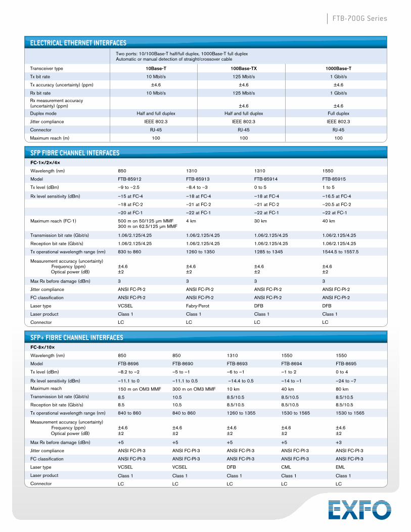
ELECTRICAL ETHERNET INTERFACESTwo ports: 10/100Base-T half/full duplex, 1000Base-T full duplexAutomatic or manual detection of straight/crossover cable
Transceiver type 10Base-T 100Base-TX 1000Base-T
Tx bit rate 10 Mbit/s 125 Mbit/s 1 Gbit/s
Tx accuracy (uncertainty) (ppm) ±4.6 ±4.6 ±4.6
Rx bit rate 10 Mbit/s 125 Mbit/s 1 Gbit/s
Rx measurement accuracy (uncertainty) (ppm) ±4.6 ±4.6
Duplex mode Half and full duplex Half and full duplex Full duplex
Jitter compliance IEEE 802.3 IEEE 802.3 IEEE 802.3
Connector RJ-45 RJ-45 RJ-45
Maximum reach (m) 100 100 100
SFP FIBRE CHANNEL INTERFACESFC-1×/2×/4×
Wavelength (nm) 850 1310 1310 1550
Model FTB-85912 FTB-85913 FTB-85914 FTB-85915
Tx level (dBm) –9 to –2.5 –8.4 to –3 0 to 5 1 to 5
Rx level sensitivity (dBm) –15 at FC-4 –18 at FC-4 –18 at FC-4 –16.5 at FC-4
–18 at FC-2 –21 at FC-2 –21 at FC-2 –20.5 at FC-2
–20 at FC-1 –22 at FC-1 –22 at FC-1 –22 at FC-1
Maximum reach (FC-1) 500 m on 50/125 µm MMF300 m on 62.5/125 µm MMF
4 km 30 km 40 km
Transmission bit rate (Gbit/s) 1.06/2.125/4.25 1.06/2.125/4.25 1.06/2.125/4.25 1.06/2.125/4.25
Reception bit rate (Gbit/s) 1.06/2.125/4.25 1.06/2.125/4.25 1.06/2.125/4.25 1.06/2.125/4.25
Tx operational wavelength range (nm) 830 to 860 1260 to 1350 1285 to 1345 1544.5 to 1557.5
Measurement accuracy (uncertainty) Frequency (ppm) Optical power (dB)
±4.6±2
±4.6±2
±4.6±2
±4.6±2
Max Rx before damage (dBm) 3 3 3 3
Jitter compliance ANSI FC-PI-2 ANSI FC-PI-2 ANSI FC-PI-2 ANSI FC-PI-2
FC classification ANSI FC-PI-2 ANSI FC-PI-2 ANSI FC-PI-2 ANSI FC-PI-2
Laser type VCSEL Fabry-Perot DFB DFB
Laser product Class 1 Class 1 Class 1 Class 1
Connector LC LC LC LC
SFP+ FIBRE CHANNEL INTERFACESFC-8×/10×
Wavelength (nm) 850 850 1310 1550 1550
Model FTB-8696 FTB-8690 FTB-8693 FTB-8694 FTB-8695
Tx level (dBm) –8.2 to –2 –5 to –1 –6 to –1 –1 to 2 0 to 4
Rx level sensitivity (dBm) –11.1 to 0 –11.1 to 0.5 –14.4 to 0.5 –14 to –1 –24 to –7
Maximum reach 150 m on OM3 MMF 300 m on OM3 MMF 10 km 40 km 80 km
Transmission bit rate (Gbit/s) 8.5 10.5 8.5/10.5 8.5/10.5 8.5/10.5
Reception bit rate (Gbit/s) 8.5 10.5 8.5/10.5 8.5/10.5 8.5/10.5
Tx operational wavelength range (nm) 840 to 860 840 to 860 1260 to 1355 1530 to 1565 1530 to 1565
Measurement accuracy (uncertainty) Frequency (ppm) Optical power (dB)
±4.6±2
±4.6±2
±4.6±2
±4.6±2
±4.6±2
Max Rx before damage (dBm) +5 +5 +5 +5 +3
Jitter compliance ANSI FC-PI-3 ANSI FC-PI-3 ANSI FC-PI-3 ANSI FC-PI-3 ANSI FC-PI-3
FC classification ANSI FC-PI-3 ANSI FC-PI-3 ANSI FC-PI-3 ANSI FC-PI-3 ANSI FC-PI-3
Laser type VCSEL VCSEL DFB CML EML
Laser product Class 1 Class 1 Class 1 Class 1 Class 1
Connector LC LC LC LC LC

FTB-700G Series
SYNCHRONIZATION INTERFACESExternal Clock DS1/1.5M External Clock E1/2M External Clock E1/2M Trigger 2 MHz
Tx pulse amplitude (V) 2.4 to 3.6 3.0 2.37 0.75 to 1.5
Tx pulse mask GR-499 Figure 9.5 G.703 Figure 15 G.703 Figure 15 G.703 Figure 20
Tx LBO preamplification Typical power dBdsx+0.6 dBdsx (0–133 ft)
+1.2 dBdsx (133–266 ft)+1.8 dBdsx (266–399 ft)+2.4 dBdsx (399–533 ft)+3.0 dBdsx (533–655 ft)
Rx level sensitivity TERM: ≤6 dB (cable loss only) (at 772 kHz for T1)
DSX-MON: ≤26 dB (20 dB resistive loss + cable loss ≤ 6 dB)
Bridge: ≤6 dB (cable loss only)
TERM: ≤6 dB (cable loss only) MON: ≤26 dB (20 dB resistive
loss + cable loss ≤ 6 dB)
Bridge: ≤6 dB (cable loss only)
TERM: ≤6 dB (cable loss only) MON: ≤26 dB (resistive loss
+ cable loss ≤ 6 dB) Bridge: ≤6 dB (cable loss only)
≤6 dB (cable loss only)
Transmission bit rate 1.544 Mbit/s ± 4.6 ppm 2.048 Mbit/s ± 4.6 ppm 2.048 Mbit/s ± 4.6 ppmReception bit rate 1.544 Mbit/s ± 50 ppm 2.048 Mbit/s ± 50 ppm 2.048 Mbit/s ± 50 ppm
Intrinsic jitter (Tx)ANSI T1.403 section 6.3
GR-499 section 7.3G.823 section 6.1 G.823 section 6.1 G.703 table 11
Input jitter tolerance AT&T PUB 62411GR-499 section 7.3
G.823 section 7.2G.813
G.823 section 7.2G.813
G.823 section 7.1G.751 section 3.3
Line coding AMI and B8ZS AMI and HDB3 AMI and HDB3Input impedance (resistive termination) 75 ohms ± 5 %, unbalanced 75 ohms ± 5 %, unbalanced 75 ohms ± 5 %, unbalanced 75 ohms ± 5 %, unbalancedConnector type BNC a BNC a BNC BNC
Note
a. Adaptation cable required for BANTAM.
FIBRE CHANNEL FUNCTIONAL SPECIFICATIONSTESTING 1×, 2×, 4×, 8×, 10×
BERT Framed FC-2
Patterns (BERT) PRBS 2E31-1, 2E23-1, 2E20-1, 2E15-1, 2E11-1, 2E9-1, one user-defined pattern and capability to invert patterns
Error insertion Bit error, amount and rate
Error measurement Bit error, symbol error, oversize error, crc error, undersize error and block error (10× only)
Alarm detection LOS, pattern loss, link down, local and remote fault (10× only)
Buffer-to-buffer credit testing Buffer-to-buffer credity estimation based on latency
Latency Round-trip latency
SFP FTTA INTERFACESCPRI/OBSAI 2.4576/3.072 Gbit/s
Wavelength (nm) 850 1310 1310 1550
Model FTB-8590 FTB-8190 FTB-8191 FTB-8192
Tx level (dBm) –9 to –3 –5 to 0 –2 to 3 –2 to 3
Rx level sensitivity (dBm) –18 to 0 –18 to 0 –27 to –9 –28 to –9
Maximum reach 300 m on OM3 MMF 15 km 40 km 80 km
Transmission bit rate (Gbit/s) 2.4576/3.072 2.4576/3.072 2.4576/3.072 2.4576/3.072
Reception bit rate (Gbit/s) 2.4576/3.072 2.4576/3.072 2.4576/3.072 2.4576/3.072
Tx operational wavelength range (nm) 830 to 860 1270 to 1360 1280 to 1355 1500 to 1580
Measurement accuracy (uncertainty) Optical power (dB) ±2 ±2 ±2 ±2
Max Rx before damage (dBm) +5 +5 +3 +3
Jitter compliance IEEE 802.3 GR-253 (SONET)G-958 (SDH)
GR-253 (SONET)G-958 (SDH)
GR-253 (SONET)G-958 (SDH)
Laser type VCSEL DFB DFB CML
Laser product Class 1 Class 1 Class 1 Class 1
Connector LC LC LC LC
Transceiver type SFP SFP SFP SFP

FTB-700G Series
SONET FUNCTIONAL SPECIFICATIONS SDH FUNCTIONAL SPECIFICATIONSOptical interfaces OC-1, OC-3, OC-12, OC-48, OC-192 Optical interfaces STM-0, STM-1, STM-4, STM-16, STM-64
Available wavelengths (nm) 1310, 1550 Available wavelengths (nm) 1310, 1550
Clocking Internal, loop-timed, external (BITS) Clocking Internal, loop-timed, external (MTS/SETS), 2 MHz
Mappings
VT1.5 Bulk AU-3-TU-11, AU-4-TU-11 Bulk
VT2 Bulk AU-3 -TU-12, AU-4-TU-12 Bulk
STS-1 SPE Bulk AU-3, AU-4-TU-3 Bulk
STS-3c Bulk AU-4 Bulk
STS-12c/48c/192c, SPE Bulk AU-4-4c/16c/64c Bulk
SONET overhead analysis and manipulation A1, A2, J0, E1, F1, D1-D12, K1, K2, S1, M0, M1, E2, J1, C2, G1, F2, H4, Z3, Z4, Z5, N1, N2, Z6, Z7
SDH overhead analysis and manipulation A1, A2, J0, E1, F1, D1-D12, K1, K2, S1, M0, M1 G1, F2, F3, K3, N1, N2, K4, E2, J1, C2, H4
Error insertion
OC-1, OC-3, OC-12, OC-48, OC-192 Section BIP (B1), line BIP (B2), path BIP (B3), BIP-2, REI-L, REI-P, REI-V, FAS, bit error
STM-0, STM-1, STM-4, STM-16, STM-64 RS-BIP (B1), MS-BIP (B2), HP-BIP (B3), MS-REI, HP-REI, LP-BIP-2, LP-REI, FAS, bit error
Error measurement
OC-1, OC-3, OC-12, OC-48, OC-192 Section BIP (B1), line BIP (B2), path BIP (B3), BIP-2, REI-L, REI-P, REI-V, FAS, bit error
STM-0, STM-1, STM-4, STM-16, STM-64 RS-BIP (B1), MS-BIP (B2), HP-BIP (B3), MS-REI, HP-REI, LP-BIP-2, LP-REI, FAS, bit error
Alarm insertion
OC-1, OC-3, OC-12, OC-48, OC-192 LOS, LOF-S, SEF, AIS-L, RDI-L, AIS-P, LOP-P, LOM, PDI-P, RDI-P, ERDI-PCD, ERDI-PPD, ERDI-PSD, UNEQ-P, AIS-V, LOP-V, RDI-V, ERDI-VCD, ERDI-VPD, ERDI-VSD, RFI-V, UNEQ-V, pattern loss
STM-0, STM-1, STM-4, STM-16, STM-64 LOS, LOF, OOF, MS-AIS, MS-RDI, AU-AIS, AU-LOP, H4-LOM, HP-ERDI-CD, HP-ERDI-PD, HP-ERDI-SD, LP-ERDI-CD, LP-ERDI-PD, LP-ERDI-SD, HP-UNEQ, TU-AIS, LP-RFI, LP-RDI, LP-RFI, LP-UNEQ, pattern loss
Alarm detection
OC-1, OC-3, OC-12, OC-48, OC-192 LOS, LOC, LOF-S, SEF, TIM-S, AIS-L, RDI-L, AIS-P, LOP-P, LOM, PDI-P, RDI-P, ERDI-PCD, ERDI-PPD, ERDI-PSD, PLM-P, UNEQ-P, TIM-P, AIS-V, LOP-V, RDI-V, ERDI-VCD, ERDI-VPD, ERDI-VSD, RFI-V, UNEQ-V, TIM-V, PLM-V, pattern loss
STM-0, STM-1, STM-4, STM-16, STM-64 LOS, RS-LOF, LOC, RS-OOF, RS-TIM, MS-AIS, MS-RDI, AU-AIS, AU-LOP, H4-LOM, HP-RDI, HP-ERDI-CD, HP-ERDI-PD, HP-ERDI-SD, LP-ERDI-CD, LP-ERDI-PD, LP-ERDI-SD, HP-PLM, HP-UNEQ, HP-TIM, TU-AIS, LP-RFI, LP-RDI, LP-RFI, LP-UNEQ, LP-TIM, LP-PLM, pattern loss
Frequency alarm on all supported interfaces
Patterns
VT1.5/2 2E9-1, 2E11-1, 2E15-1, 2E20-1, 2E23-1, 2E31-1, 1100, 1010, 1111, 0000, 1-in-8, 1-in-16, 32-bit programmable (inverted or non-inverted), bit errors
TU-11/12/3 2E9-1, 2E11-1, 2E15-1, 2E20-1, 2E23-1, 2E31-1, 1100, 1010, 1111, 0000, 1-in-8, 1-in-16, 32-bit programmable (inverted or non-inverted), bit errors
STS-1, STS-3c/12c/48c/192c 2E9-1, 2E11-1, 2E15-1, 2E20-1, 2E23-1, 2E31-1, 1100, 1010, 1111, 0000, 1-in-8, 1-in-16, 32-bit programmable (inverted or non-inverted), bit errors
AU-3/AU-4/AU-4-4c/16c/64c 2E9-1, 2E11-1, 2E15-1, 2E20-1, 2E23-1, 2E31-1, 1100, 1010, 1111, 0000, 1-in-8, 1-in-16, 32-bit programmable (inverted or non-inverted), bit errors
Pattern loss and bit error generation and analysis supported on all patterns
SONET/SDH TEST FEATURESFrequency measurements Supports clock frequency measurements (i.e., received frequency and deviation of the input signal clock from nominal frequency),
displayed in ppm, for optical and electrical interfaces. Measurements are performed using a local oscillator.
Frequency offset generation Supports offsetting the clock of the transmitted signal on a selected interface to exercise clock recovery circuitry on network elements.
Performance monitoring The following ITU-T recommendations, and corresponding performance monitoring parameters, are supported on the FTB-700G Series.ITU-T recommendationG.821G.828G.829M.2100M.2101
Performance monitoring statisticsES, EFS, EC, SES, UAS, ESR, SESR, DMES, EFS, EB, SES, BBE, SEP, UAS, ESR, SESR, BBER, SEPIES, EFS, EB, SES, BBE, UAS, ESR, SESR, BBERES, SES, UAS, ESR, SESRES, SES, BBE, UAS, ESR, SESR, BBER
Pointer adjustment and analysis Generation and analysis of STS/AU and VT/TU pointer adjustments as per GR-253, and ITU-T G.707Generation› Pointer increment and decrement› Pointer jump with or without NDF› Pointer value
Analysis› Pointer increments and decrements› Pointer jumps with or without NDF› Pointer value and cumulative offset
Pointer sequence testing Perform pointer sequence testing as per G.783, GR253 and T1.105-3 standards.
Service disruption time (SDT) measurements
The service disruption time test tool measures the time during which there is a disruption of service due to the network switching from the active channels to the backup channels.Measurements: last disruption, shortest disruption, longest disruption, average disruption, total disruption, and service disruption count.
Round-trip delay (RTD) measurements
The round-trip delay test tool measures the time required for a bit to travel from the FTB-700G Series transmitter back to its receiver after crossing a far-end loopback. Measurements are provided on all supported FTB-700G Series interfaces and mappings. Measurements: last, minimum, maximum, average; measurement count: no. of successful RTD tests and failed measurement count.
APS message control and monitoring Ability to monitor and set up automatic protection switching messages (K1/K2 byte of SONET/SDH overhead).
Synchronization status Ability to monitor and set up synchronization status messages (S1 byte of SONET/SDH overhead).
Signal label control and monitoring Ability to monitor and set up payload signal labels (C2, V5 byte of SONET overhead).
Tandem connection monitoring (TCM) a
Tandem connection monitoring (TCM) is used to monitor the performance of a subsection of a SONET/SDH path routed via different network providers. The FTB-700G Series supports transmitting and receiving alarms and errors on a TCM link; also, transmission and monitoring of the tandem connection (TC) trace can be generated to verify the connection between TCM equipment.Error generation: TC-IEC, TC-BIP, TC-REI, TC-OEIError analysis: TC-IEC, TC-REI, TC-OEI, TC-VIOL (non-standardized alarm)Alarm generation: TC-RDI, TC-UNEQ, TC-ODI, TC-LTC, TC-IAISAlarm analysis: TC-TIM, TC-RDI, TC-UNEQ, TC-ODI, TC-LTC, TC-IAIS
Through mode Perform Through mode analysis of any incoming optical line (OC-1/STM-0, OC-3/STM-1, OC-12/STM-4, OC-48/STM-16, OC-192/STM-64) transparently.
Notea. STS/AU and VT/TU supported as per ITU G.707 option 2.

FTB-700G Series
OTN TEST FEATURESOTN Standards compliance ITU-T G.709, ITU G.798, ITU G.872
Interfaces OTU1 (2.6660 Gbit/s), OTU2 (10.7092 Gbit/s), OTU1e (11.0491 Gbit/s), OTU2e (11.0957 Gbit/s), OTU1f (11.2701 Gbit/s), OTU2f (11.3176 Gbit/s)
OTU Layer Errors OTU-FAS, OTU-MFAS, OTU-BEI, OTU-BIP-8
Alarms LOF, OOF, LOM, OOM, OTU-AIS, OTU-TIM, OTU-BDI, OTU-IAE, OTU-BIAE
Traces 64-bytes Trail Trace Identifier (TTI) as defined in ITU-T G.709
ODU TCM Layer Errors TCMi-BIP-8, TCMi-BEI (i = 1 to 6)
Alarms TCMi-LTC, TCMi-TIM, TCMi-BDI, TCMi-IAE, TCMi-BIAE
Traces 64-byte Trail Trace Identifier (TTI) as defined in ITU-T G.709
ODU Layer Errors ODU-BIP-8, ODU-BEI
Alarms ODU-AIS, ODU-OCI, ODU-LCK, ODU-TIM, ODU-BDI, ODU-FSF, ODU-BSF, ODU-FSD, ODU-BSD
Traces Generates 64-byte Trail Trace Identifier (TTI) as defined in ITU-T G.709
FTFL b As defined in ITU-T G.709
OPU Layer Alarms OPU-PLM, OPU-AIS, OPU-CSF
Payload type (PT) label Generates and displays received PT value
Forward Error Correction (FEC)
Errors FEC-Correctable (Codeword), FEC-Uncorrectable (Codeword), FEC-Correctable (Symbol), FEC-Correctable (Bit), and FEC-Stress (Codeword)
Pattern Patterns 2E-9, 2E-15, 2E-23, 2E-31, NULL, 32-bit programmable (inverted or noninverted)
Error Bit error
Alarm Pattern loss
ADDITIONAL OTN FUNCTIONFrequency measurements Supports clock frequency measurements (i.e., received frequency and deviation of the input signal clock from nominal frequency),
displayed in ppm. Measurements are performed using a local oscillator.
Frequency offset generation Supports offsetting the clock of the transmitted signal on a selected interface to exercise clock recovery circuitry on network elements.
Performance monitoring The following ITU-T recommendations and corresponding performance monitoring parameters are supported on the FTB-700G Series.
ITU-T recommendationG.821M.2100
Performance monitoring statisticsES, EFS, EC, SES, UAS, ESR, SESR, DMES, SES, UAS, ESR, SESR
Service disruption time (SDT) measurements
The service disruption time test tool measures the time during which there is a disruption of service due to the network switching from the active channels to the backup channels. Measurements: last disruption, shortest disruption, longest disruption, average disruption, total disruption, and service disruption count.
Round-trip delay (RTD) measurements
The round-trip delay test tool measures the time required for a bit to travel from the transmitter back to its receiver after crossing a far-end loopback. Measurements are supported on all interfaces and mappings. Measurements: last RTD time, minimum, maximum, average, measurement count (no. of successful RTD tests) and failed measurement count.
Through mode Perform Through mode analysis of any incoming OTN signal transparently.

FTB-700G Series
ETHERNET TEST FEATURESEtherSAM (ITU-T Y.1564) Perform service configuration and performance tests as per ITU-T Y.1564, including EBS, CBS and EMIX. Tests can be performed using
remote loopback, or dual test set mode for bidirectional results.
RFC 2544 Throughput, back-to-back, frame loss and latency measurements according to RFC 2544. Frame size: RFC-defined sizes, user-configurable between 1-7 sizes.
Traffic generation and monitoring
Traffic generation and shaping of up to 16 streams of Ethernet and IP traffic, including the simultaneous monitoring of throughput, frame loss, packet jitter, latency and out-of-sequence frames.
Carrier Ethernet OAM
Supports three S-OAM modes, MEF, Y.1731 and 802.1ag. CCM generation and monitoring, loopback, test, frame loss, synthetic loss and frame delay. Alarm generation: AIS, RDI, LCK, CSF (C-LOS, C-RDI, C-FDI, C-DCI). Alarm monitoring: RDI, AIS, LCK, CSF, loss of continuity, mismerge, unexpected MEP, unexpected MEG/MD level; unexpected period supports S-OAM responder, S-OAM link trace, ping and traceroute, filters and packet capture.
Through mode Sectionalize traffic between a service provider’s network and customer premises equipment.
BER testing Up to layer 4 supported with or without VLAN Q-in-Q.
Packet capture and filters Ability to perform 10BASE-T all the way up to 10 GigE at full line rate with packet capture and decode. Ability to configure four filters with full decoding up to 10G including automatic triggers.
Patterns (BERT) PRBS 2E9-1, PRBS 2E11-1, PRBS 2E15-1, PRBS 2E20-1, PRBS 2E23-1, PRBS 2E31-1 and one-user pattern. Capability to invert patterns.
Error measurement (BERT) Bit error, bit mismatch 0, bit mismatch 1.
Error measurements Jabber/giant, runt, undersize, oversize, FCS, symbol, alignment, collision, late collision, excessive collision, 10G block error.
Alarm detection LOS, link down, pattern loss, frequency, 10G local/remote fault.
VLAN stacking Generate streams with up to two layers of VLAN (including IEEE 802.1ad Q-in-Q tagged VLAN) traffic by VLAN ID or VLAN priority at any of the stacked VLAN layers.
MPLS Capability to generate and analyze streams with up to two layers of MPLS labels and to filter received traffic by MPLS label or COS.
Cable testing Category 5 cable (or better), 100 UTP/STP cable, ≤120 meters.
Service disruption time (SDT) Includes statistics such as longest, shortest, last, average, count, total and pass/fail thresholds.
TCP throughput True wire-speed, TCP throughput test for undisputable SLA reinforcement for Ethernet services.
One-way delay Measurement of the one-way frame delay at up to 10G as part of EtherSAM (Y.1564) and RFC 2544.
IPv6 testing Includes BERT, RFC 2544, traffic generation and monitoring, background streams, Smart Loopback, Remote Loopback, ping and traceroute.
10 GigE WAN testing Includes WAN interface sublayer, J0/J1 trace and C2 label generation, J0/J1 trace and C2 label monitoring.
10 GigE WAN alarm monitoring Includes SEF, LOF, AIS-L, RDI-L, AIS-P, RDI-P, LCD-P, LOP-P, PLM-P, UNEQ-P, ERDI-P, WIS link down, B1, B2, B3, REI-L, REI-P.
ADDITIONAL FEATURES FTTA BER testing Includes BER measurement, bit error injection, round-trip delay measurement and pass/fail verdict for 2.5 and 3.1 Gbit/s rates.
1588 PTP Validates 1588 PTP packet network synchronization services, emulates PTP clients, generates and analyzes messages between master/clients, clock quality level and IPDV.
SyncE Validates SyncE frequency, ESMC messages and clock quality levels.
Power measurement Supports power measurement at all times, displayed in dBm (dBdsx for DS1 and DS3), for optical and electrical interfaces.
Power-up and restore In the event of a power failure to the unit, the active test configuration and test logger are saved and restored upon boot-up. Applicable to transport test applications only.
Save and load configuration Store and load test configurations to/from a non-volatile USB memory stick or internal flash.
Pass/fail analysis Provides a pass/fail outcome with user-adjustable thresholds, based on bit-error-rate and/or service disruption time.
Alarm hierarchy Alarms are displayed according to a hierarchy based on root cause. Secondary effects are not displayed. This hierarchy serves to facilitate alarm analysis.
Report generation Generate test reports on the unit or exported via USB.
Event logger Log test results with absolute or relative time and date, details and duration of events, color-coded events and pass/fail outcome.
Remote control Remote control via VNC or Remote Desktop.
Remote loopback Detects other AXS-200/850, FTB-860 and FTB-700G Series units and sets them into Smart Loopback mode.
Dual test set Detects and connects to any of EXFO’s Ethernet testers to perform bidirectional RFC 2544 and EtherSAM testing.
Dual-port mode Enables any Ethernet test, such as EtherSAM, RFC 2544, Traffic Generation and monitoring, or BERT to run directly to itself using one self-contained unit with loopback.
IP tools Perform ping and traceroute functions.
Smart loopback Return Ethernet traffic to the local unit by swapping packet overhead up to layer 4.

FTB-700G Series
UPGRADESSFP upgrades FTB-8590 SFP module GigE/FC/2FC, CPRI/OBSAI 2.45/3.07 Gbit/s at 850 nm, MM, <500 m
FTB-85910 SFP modules 100 Base-FX, 1340 nm, MM, 2 km
FTB-85911 SFP modules 100 Base-LX10, 1310 nm, SM, 15 km
FTB-85912 SFP modules GigE/FC/2FC/4FC at 850 nm, <500 m
FTB-8190 SFP module; rates: 155/622 Mbit/s, 2.5/2.7 Gbit/s, GigE/FC/2FC, CPRI/OBSAI 2.45/3.07 Gbit/s at 1310 nm, LC connector, 15 km reach
FTB-8191 SFP module; rates: 155/622 Mbit/s, 2.5/2.7 Gbit/s, GigE/FC/2FC; CPRI/OBSAI 2.45/3.07 Gbit/s at 1310 nm, LC connector, 40 km reach
FTB-8192 SFP module; rates: 155/622 Mbit/s, 2.5/2.7 Gbit/s, GigE/FC/2FC; 1550 nm, LC connector, 80 km reach
FTB-8193 SFP module; rates: 155/622 Mbit/s, 2.5/2.7 Gbit/s, GigE/FC/2FC; 1550 nm, LC connector, 40 km reach
FTB-85913 SFP modules GigE/FC/2FC/4FC at 1310 nm, 4 km
FTB-85914 SFP modules GigE/FC/2FC/4FC at 1310 nm, 30 km
FTB-85915 SFP modules GigE/FC/2FC/4FC at 1550 nm, <50 km
SFP+ upgrades FTB-8690 SFP+ modules 10FC/10 GigE at 850 nm, MM, 300 m
FTB-8691 SFP+ modules 10 GigE at 1310 nm, 10 km
FTB-8693 SFP+ modules 9.953-10.709/11.3, 8FC/10FC/10 GigE at 1310 nm, SMF, 10 km
FTB-8694 SFP+ modules 8FC/10FC/10 GigE at 1550 nm, 40 km
FTB-8695 SFP+ modules 8FC/10FC/10 GigE at 1550 nm, 80 km
Bidirectional SFP upgrades
FTB-8596 SFP modules bidirectional 1490 Tx 1310 Rx 1000 BASE-BX10
FTB-8597 SFP modules bidirectional 1310 Tx 1490 Rx 1000 BASE-BX10
FTB-8598 SFP modules bidirectional 1310 Tx 1490/1550 Rx 1000 BASE-BX
FTB-8599 SFP modules bidirectional 1550 Tx 1310 Rx 1000 BASE-BX
FTB-700G Series
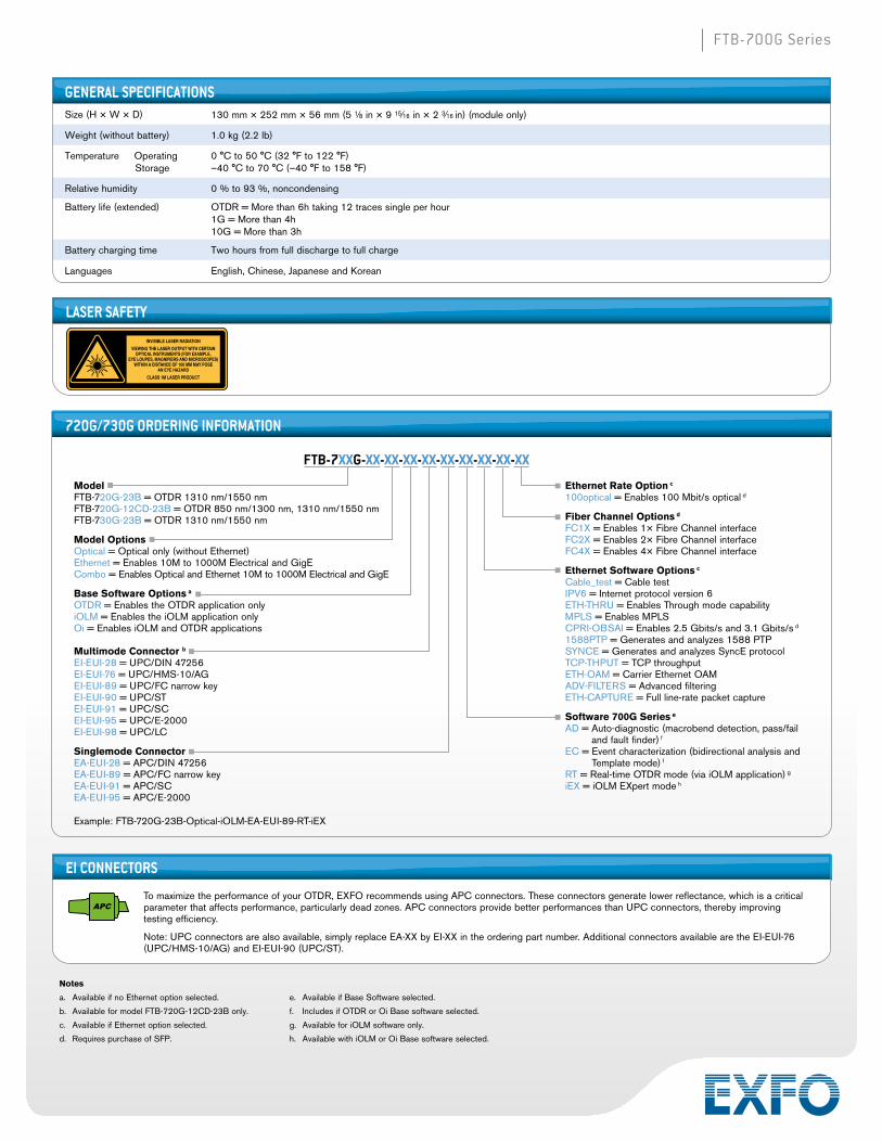
720G/730G ORDERING INFORMATION
ModelFTB-720G-23B = OTDR 1310 nm/1550 nmFTB-720G-12CD-23B = OTDR 850 nm/1300 nm, 1310 nm/1550 nmFTB-730G-23B = OTDR 1310 nm/1550 nm
Model OptionsOptical = Optical only (without Ethernet)Ethernet = Enables 10M to 1000M Electrical and GigECombo = Enables Optical and Ethernet 10M to 1000M Electrical and GigE
Base Software Options a
OTDR = Enables the OTDR application onlyiOLM = Enables the iOLM application onlyOi = Enables iOLM and OTDR applications
Multimode Connector b
EI-EUI-28 = UPC/DIN 47256 EI-EUI-76 = UPC/HMS-10/AG EI-EUI-89 = UPC/FC narrow key EI-EUI-90 = UPC/ST EI-EUI-91 = UPC/SC EI-EUI-95 = UPC/E-2000 EI-EUI-98 = UPC/LC
Singlemode ConnectorEA-EUI-28 = APC/DIN 47256EA-EUI-89 = APC/FC narrow keyEA-EUI-91 = APC/SCEA-EUI-95 = APC/E-2000
FTB-7XXG-XX-XX-XX-XX-XX-XX-XX-XX-XX
Ethernet Rate Option c
100optical = Enables 100 Mbit/s optical d
Fiber Channel Options d FC1X = Enables 1× Fibre Channel interface
FC2X = Enables 2× Fibre Channel interface
FC4X = Enables 4× Fibre Channel interface
Ethernet Software Options c
Cable_test = Cable testIPV6 = Internet protocol version 6ETH-THRU = Enables Through mode capabilityMPLS = Enables MPLSCPRI-OBSAI = Enables 2.5 Gbits/s and 3.1 Gbits/s d
1588PTP = Generates and analyzes 1588 PTPSYNCE = Generates and analyzes SyncE protocolTCP-THPUT = TCP throughputETH-OAM = Carrier Ethernet OAMADV-FILTERS = Advanced filteringETH-CAPTURE = Full line-rate packet capture
Software 700G Series e
AD = Auto-diagnostic (macrobend detection, pass/fail and fault finder) f
EC = Event characterization (bidirectional analysis and Template mode) f
RT = Real-time OTDR mode (via iOLM application) g
iEX = iOLM EXpert mode h
Example: FTB-720G-23B-Optical-iOLM-EA-EUI-89-RT-iEX
GENERAL SPECIFICATIONS Size (H × W × D) 130 mm × 252 mm × 56 mm (5 1⁄8 in × 9 15⁄16 in × 2 3⁄16 in) (module only)
Weight (without battery) 1.0 kg (2.2 lb)
Temperature Operating Storage
0 °C to 50 °C (32 °F to 122 °F)–40 °C to 70 °C (–40 °F to 158 °F)
Relative humidity 0 % to 93 %, noncondensing
Battery life (extended) OTDR = More than 6h taking 12 traces single per hour1G = More than 4h10G = More than 3h
Battery charging time Two hours from full discharge to full charge
Languages English, Chinese, Japanese and Korean
Notes
a. Available if no Ethernet option selected.
b. Available for model FTB-720G-12CD-23B only.
c. Available if Ethernet option selected.
d. Requires purchase of SFP.
e. Available if Base Software selected.
f. Includes if OTDR or Oi Base software selected.
g. Available for iOLM software only.
h. Available with iOLM or Oi Base software selected.
LASER SAFETY
INVISIBLE LASER RADIATIONVIEWING THE LASER OUTPUT WITH CERTAIN
OPTICAL INSTRUMENTS (FOR EXAMPLE, EYE LOUPES, MAGNIFIERS AND MICROSCOPES)
WITHIN A DISTANCE OF 100 MM MAY POSE AN EYE HAZARD
CLASS 1M LASER PRODUCT
EI CONNECTORS
To maximize the performance of your OTDR, EXFO recommends using APC connectors. These connectors generate lower reflectance, which is a critical parameter that affects performance, particularly dead zones. APC connectors provide better performances than UPC connectors, thereby improving testing efficiency.
Note: UPC connectors are also available, simply replace EA-XX by EI-XX in the ordering part number. Additional connectors available are the EI-EUI-76 (UPC/HMS-10/AG) and EI-EUI-90 (UPC/ST).

EXFO is certified ISO 9001 and attests to the quality of these products. EXFO has made every effort to ensure that the information contained in this specification sheet is accurate. However, we accept no responsibility for any errors or omissions, and we reserve the right to modify design, characteristics and products at any time without obligation. Units of measurement in this document conform to SI standards and practices. In addition, all of EXFO’s manufactured products are compliant with the European Union’s WEEE directive. For more information, please visit www.EXFO.com/recycle. Contact EXFO for prices and availability or to obtain the phone number of your local EXFO distributor.
For the most recent version of this spec sheet, please go to the EXFO website at www.EXFO.com/specs.
In case of discrepancy, the Web version takes precedence over any printed literature.
FTB-700G Series
Distributed by: Mega Hertz 800 883-8839 [email protected] www.go2mhz.com
SPFTB700GSERIES.2AN © 2014 EXFO Inc. All rights reserved. 2008
Printed in Canada 14/04
720G+/730G+ ORDERING INFORMATION
ModelFTB-720G+-23B = OTDR 1310 nm/1550 nmFTB-720G+-12CD-23B = OTDR 850 nm/1300 nm,
1310 nm/1550 nmFTB-730G+-23B = OTDR 1310 nm/1550 nm
Model OptionsOptical = Optical only (without Ethernet)Ethernet = Enables 10M to 1000M Electrical and GigECombo = Enables Optical and Ethernet 10M to 1000M
Electrical and GigE
Base Software Options a
OTDR = Enables the OTDR application onlyiOLM = Enables the iOLM application onlyOi = Enables iOLM and OTDR applications
Multimode Connector b
EI-EUI-28 = UPC/DIN 47256 EI-EUI-76 = UPC/HMS-10/AG EI-EUI-89 = UPC/FC narrow key EI-EUI-90 = UPC/ST EI-EUI-91 = UPC/SC EI-EUI-95 = UPC/E-2000 EI-EUI-98 = UPC/LC
Singlemode ConnectorEA-EUI-28 = APC/DIN 47256EA-EUI-89 = APC/FC narrow keyEA-EUI-91 = APC/SCEA-EUI-95 = APC/E-2000
Software 700G Series c
AD = Auto-diagnostic (macrobend detection, pass/fail and fault finder) d
EC = Event characterization (bidirectional analysis and Template mode) d
RT = Real-time OTDR mode (via iOLM application) e
iEX = iOLM EXpert mode f
Transport Base Options g
SONET = SONET testingSDH = SDH testingSONET-SDH = SONET and SDH testing
FTB-7XXG+-XX-XX-XX-XX-XX-XX-XX-XX-XX-XX-XX-XX-XX
Transport Rate Options g
52M = 52 Mbit/s (OC-1/STM-0) h, i
155M = 155 Mbit/s (OC-3/STM-1) i
622M = 622 Mbit/s (OC12/STM-4) i
2488M = 2.5 Gbit/s (OC48/STM-16) i
9953M = 10 Gbit/s (OC192/STM-64) j
Ethernet Rate Option g
100optical = Enables 100 Mbit/s optical i10GigE = Enables 10 GigE LAN/WAN j
Fiber Channel Options h FC1X = Enables 1× Fibre Channel interface i
FC2X = Enables 2× Fibre Channel interface i
FC4X = Enables 4× Fibre Channel interface i FC8X = Enables 8× Fibre Channel interface i FC10X = Enables 10× Fibre Channel interface j
Transport Software Options g
00 = Without Transport Software optionTCM = Tandem connection monitoring
Ethernet Software Options g
Cable_test = Cable testIPV6 = Enables Internet protocol version 6ETH-THRU = Enables Through mode capabilityMPLS = Enables MPLSCPRI-OBSAI = Enables 2.5 Gbits/s and 3.1 Gbits/s g
1588PTP = Generates and analyzes 1588 PTPSYNCE = Generates and analyzes SyncE protocolTCP-THPUT = TCP throughputETH-OAM = Carrier Ethernet OAMADV-FILTERS = Advanced filteringETH-CAPTURE = Full line-rate packet capture
OTN Rate Options 00 = Without OTN rate optionOTU1 = OTN optical rate 2.666 Gbit/s i
OTU2 = OTN optical rate 10.709 Gbit/s j
OTU2-1e-2e = OTN optical rates 11.049/11.096 Gbit/s j
OTU2-1f-2f = OTN optical rates 11.270/11.318 Gbit/s j
Example: FTB-730G+-23B-Optical-IOLM-EA-EUI-89-RT-iEX
Notes
a. Available if no Ethernet option selected.
b. Available for model FTB-720G+-12CD-23B only.
c. Available if Base Software selected.
d. Included if OTDR or Oi Base software selected.
e. Available for iOLM software only.
f. Available with iOLM or Oi Base software selected.
g. Available if Ethernet option selected.
h. Included if Ethernet selected.
i. Requires purchase of SFP.
j. Requires purchase of SFP+.
EI CONNECTORS
To maximize the performance of your OTDR, EXFO recommends using APC connectors. These connectors generate lower reflectance, which is a critical parameter that affects performance, particularly dead zones. APC connectors provide better performances than UPC connectors, thereby improving testing efficiency.
Note: UPC connectors are also available, simply replace EA-XX by EI-XX in the ordering part number. Additional connectors available are the EI-EUI-76 (UPC/HMS-10/AG) and EI-EUI-90 (UPC/ST).