optara project specifications raffinaderij...
TRANSCRIPT
OPTARA PROJECT SPECIFICATIONS
RAFFINADERIJ ANTWERPEN
Amendment to Total general
specification GS RM ISL 001
thermal insulation of piping
vessels and tanks
T4RA‐55‐GEN‐A4‐0008
REVISION 1 Responsibility TOTAL/RC/IND 15 February 2013
OPTARA PROJECT
RAFFINADERIJ ANTWERPEN
REVISION 1 Amendment to Total general specification GS RM ISL
001 thermal insulation of piping vessels and tanks
15 February 2013
Revision tracking
Revision Revision date Scope of Revision 1 15 February 2013 Approved for Optara Project
OPTARA PROJECT
RAFFINADERIJ ANTWERPEN
REVISION 1 Amendment to Total general specification GS RM ISL
001 thermal insulation of piping vessels and tanks
15 February 2013
Table of contents
Section Contents Page T4RA‐55‐GEN‐A4‐0008

ISSUED FOR DESIGN06 Sep 2012
FinalFor Design Dossier
By Marcel Agterhof at 01 12 :21 Dec 2012
T4RA OPTARA Project TOTAL, Antwerp T4RA-55-GEN-A4-0008 AMENDMENT TO SPECIFICATION Rev. 1 GS RM ISL 001 Thermal Insulation for Piping, Vessels and Tanks 5 Sep 2012 CONFIDENTIAL Page 2 of 12
Table of Contents 1. INTRODUCTION...........................................................................................................3
2. REFERENCES.............................................................................................................3 2.1. Client Specifications................................................................................................................3 2.2. Project Specifications..............................................................................................................3 2.3. Standards ................................................................................................................................3
3. AMENDMENTS TO TOTAL GENERAL SPECIFICATION ....................................................4 3.1. Section 1, Subject ...................................................................................................................4 3.2. Section 2, Reference documents, TOTAL General Specification...........................................4 3.3. Section 3, Applicability ............................................................................................................4 3.4. Section 5, paragraph 5.1.1 General ........................................................................................4 3.5. Section 5.1.4 Personnel Protection (PP) ................................................................................6 3.6. Section 5.2 Extent of the thermal insulation work ...................................................................6 3.7. Section 5, paragraph 5.3.1 Anti- Corrosion Protection ...........................................................7 3.8. Additional requirements for ACOUSTIC INSULATION...........................................................8
3.8.1. Classification of acoustic insulation ...........................................................................8 3.6.1.1. Class A .................................................................................................................8 3.6.1.2. Class B .................................................................................................................8 3.6.1.3. Class C .................................................................................................................9 3.8.2. Material requirements ................................................................................................9 3.8.3. Support of jacketing ................................................................................................ 10 3.8.4. Installation............................................................................................................... 10
4. ATTACHMENTS.........................................................................................................12
Abbreviations Abbreviation Meaning
TRA TOTAL Refinery Antwerp
ARDS Atmospheric Residue DeSulphurisation
MHC Mild Hydrocracker
SDA Solvent DeAsphalting
SWS Sour Water Stripper
U&O Utilities and Offisites
T4RA OPTARA Project TOTAL, Antwerp T4RA-55-GEN-A4-0008 AMENDMENT TO SPECIFICATION Rev. 1 GS RM ISL 001 Thermal Insulation for Piping, Vessels and Tanks 5 Sep 2012 CONFIDENTIAL Page 3 of 12
1. Introduction This document shall be considered as an amendment to referenced TOTAL General Specification and has been specifically prepared for the OPTARA project scope covering the ARDS revamp, MHC, SDA, SWS, Substation and related U&O scope.
This Amendment shall be read in conjunction with referenced OPTARA Project Specification Preamble which contains information of the overall Project Specification approach and order of precedence.
2. References
2.1. Client Specifications
Document Number Rev Description
GS RM ISL 001 00 Specification Thermal insulation for piping, vessels and tanks
“P” 03 Specification Thermal and Acoustic Insulation
GS RM COR 003 00 Specification Wrapping of Aluminium foil
2.2. Project Specifications
Document Number Rev Description
T4RA-00-GEN-A4-0002 00 Design Dossier - OPTARA General - Preamble
2.3. Standards
Document Number Description
ISO 15665 Acoustic insulation for pipes, valves and flanges
CINI 2012 C.I.N.I. Handbook for Insulation 2012

T4RA OPTARA Project TOTAL, Antwerp T4RA-55-GEN-A4-0008 AMENDMENT TO SPECIFICATION Rev. 1 GS RM ISL 001 Thermal Insulation for Piping, Vessels and Tanks 5 Sep 2012 CONFIDENTIAL Page 4 of 12
3. Amendments to TOTAL General Specification This section describes the amendments to aforementioned TOTAL General Specification by making direct references to its sections and paragraphs followed by a clear description of the amendment using the following categories:
- "addition" for any parts that need to be added to the General Specification
- "deletion" for any parts that need to be deleted from the General Specification
- "modification" for any parts that need to be changed in the General Specification
- “clarification” for any parts that need to be clarified in the General Specification
3.1. Section 1, Subject Addition:
The General Specification GS RM ISL 001 Thermal insulation for piping, vessels and tanks is applicable for new units (MHC fractionation and SDA).
For revamped units and U & O, TRA specification “P” is applicable, GS RM ISL 001 shall not be used.
Modification:
C.I.N.I. handbook 2012 is applicable
3.2. Section 2, Reference documents, TOTAL General Specification Modification:
TOTAL General Specification GS RM PVA 101, Refinery piping classes shall be replaced by T4RA-50-GEN-A4-0003, “Piping Material specification – Process and Utility Piping”.
3.3. Section 3, Applicability Addition
The Requirements for Acoustical Insulation are provided per chapter 3.6.of this amendment.
3.4. Section 5, paragraph 5.1.1 General Modification:
The insulation codes in section 5.1.1 shall be replaced by codes used on the OPTARA project.
An overview of the on the OPTARA Project used Insulation codes are given in table 3.4

T4RA OPTARA Project TOTAL, Antwerp T4RA-55-GEN-A4-0008 AMENDMENT TO SPECIFICATION Rev. 1 GS RM ISL 001 Thermal Insulation for Piping, Vessels and Tanks 5 Sep 2012 CONFIDENTIAL Page 5 of 12
Insulation and Tracing Codes
codes ARDS - MHC Codes SWS 99 +SDA +U&O
Type of Insulation GS RM ISL 001
P&ID
legend
Line list P&ID
legend
Line List
Not Insulated NI NI NI
Heat Conversation HC Ih HC HC HC
Personnel Protection
PP Is PP PP PP
Acoustical Insulation
Ia AC AC AC
Cold Insulation Ic CC CC CC
Electrical Traced and Insulated
ET(H)
Electrical Traced with heat transfer cement and insulated
ETT(H)
Steam traced and Insulated
ST(H) ST(H) ST ST
Steam traced with spacers and Insulated
STS(H) STS(H) ST1 ST1
Steam traced with heat transfer cement and Insulated
HC
STT(H)
Table 3.4
T4RA OPTARA Project TOTAL, Antwerp T4RA-55-GEN-A4-0008 AMENDMENT TO SPECIFICATION Rev. 1 GS RM ISL 001 Thermal Insulation for Piping, Vessels and Tanks 5 Sep 2012 CONFIDENTIAL Page 6 of 12
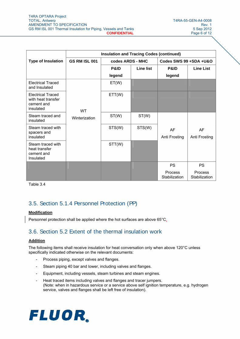
Insulation and Tracing Codes (continued)
codes ARDS - MHC Codes SWS 99 +SDA +U&O
Type of Insulation GS RM ISL 001
P&ID
legend
Line list P&ID
legend
Line List
Electrical Traced and Insulated
ET(W)
Electrical Traced with heat transfer cement and insulated
ETT(W)
Steam traced and insulated
ST(W) ST(W)
Steam traced with spacers and insulated
STS(W) STS(W)
Steam traced with heat transfer cement and Insulated
WT
Winterization
STT(W)
AF
Anti Frosting
AF
Anti Frosting
PS
Process Stabilization
PS
Process Stabilization
Table 3.4
3.5. Section 5.1.4 Personnel Protection (PP) Modification
Personnel protection shall be applied where the hot surfaces are above 65°C.
3.6. Section 5.2 Extent of the thermal insulation work Addition
The following items shall receive insulation for heat conversation only when above 120°C unless specifically indicated otherwise on the relevant documents:
- Process piping, except valves and flanges.
- Steam piping 40 bar and lower, including valves and flanges.
- Equipment, including vessels, steam turbines and steam engines.
- Heat traced items including valves and flanges and tracer jumpers. (Note: when in hazardous service or a service above self ignition temperature, e.g. hydrogen service, valves and flanges shall be left free of insulation).
T4RA OPTARA Project TOTAL, Antwerp T4RA-55-GEN-A4-0008 AMENDMENT TO SPECIFICATION Rev. 1 GS RM ISL 001 Thermal Insulation for Piping, Vessels and Tanks 5 Sep 2012 CONFIDENTIAL Page 7 of 12
- Piping with the following services shall have the valves and flanges insulated with removable boxes: Pitch, hot oil (bitumen), sulphur and superheated steam, except where explicitly indicated otherwise.
- Hot oil valves will be insulated where possible to minimize heat loss.
Items NOT to be insulated for heat conversation, regardless of temperature, unless specifically indicated otherwise on relevant documents
- Piping and equipment where it is possible to lose heat and indicated as such on the relevant documents.
- Pumps and Compressors
- Valves and flanges in steam service when above 40 bar and in process piping systems.
- Valves and flanges in hydrogen and hazardous service, except valves, flanges and bellows in H2S rich gas lines an sulphur plants (ARDS-jobs 57/98) (to prevent condensation).
- Manholes, handholes (in view of leak detection).
- Main flanges and bolts of heat exchangers and girth flanges of heat exchangers and other equipment.
- Piping and equipment operating intermittent, such as relief valves, vents, drains, steam-out, snuffing steam and decoking systems, blow-down systems, flare systems and the by-pass of heat exchangers.
- Piping and equipment supports extending outside the insulation thickness of the item.
- Expansion joints (e.g. bellows), hinge joints, line filters and line mixers. (Note: This instruction does NOT include insulation expansion joints).
- Fuel gas and pilot gas lines to individual burners (headers excluded).
- Instrument air lines
- Name Plates
3.7. Section 5, paragraph 5.3.1 Anti- Corrosion Protection Addition
Stainless steel piping under Insulation and operating at evaluated temperature up to 150°C shall be protected against stress corrosion cracking by wrapping of Aluminium foil. The Aluminium wrapping shall be applied according GS RM COR 003 Wrapping Aluminium Foil.
T4RA OPTARA Project TOTAL, Antwerp T4RA-55-GEN-A4-0008 AMENDMENT TO SPECIFICATION Rev. 1 GS RM ISL 001 Thermal Insulation for Piping, Vessels and Tanks 5 Sep 2012 CONFIDENTIAL Page 8 of 12
3.8. Additional requirements for ACOUSTIC INSULATION This Specification includes the technical requirements for the design and application of acoustic insulation to piping and equipment, in combination with or without thermal Insulation.
This Specification describes the set-up and application of sound pressure levels or required or achievable noise reductions. Dealing with acoustic problems is the work of an acoustic specialist, who will design and specify what items, shall be insulated, in what manner and to what classification.
This Specification is related to ISO 15665, in terms of classification or acoustic insulation for piping, valves and flanges.
These requirements substitute the requirements for specification “P” for all new equipment and piping that shall be provided acoustical insulation.
3.8.1. Classification of acoustic insulation
Acoustic insulation is divided in 3 classes:
Class A : Lightest noise reduction, most economic
Class B : Medium noise reduction
Class C : Heavy noise reduction
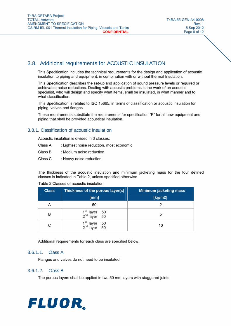
The thickness of the acoustic insulation and minimum jacketing mass for the four defined classes is indicated in Table 2, unless specified otherwise.
Table 2 Classes of acoustic insulation
Class Thickness of the porous layer(s)
[mm]
Minimum jacketing mass
[kg/m2]
A 50 2
B 1st layer 50 2nd layer 50
5
C 1st layer 50 2nd layer 50
10
Additional requirements for each class are specified below.
3.6.1.1. Class A Flanges and valves do not need to be insulated.
3.6.1.2. Class B The porous layers shall be applied in two 50 mm layers with staggered joints.

T4RA OPTARA Project TOTAL, Antwerp T4RA-55-GEN-A4-0008 AMENDMENT TO SPECIFICATION Rev. 1 GS RM ISL 001 Thermal Insulation for Piping, Vessels and Tanks 5 Sep 2012 CONFIDENTIAL Page 9 of 12
Pipe with a diameter ≤ 80 mm (≤ 3 inch) shall have maximum insulation thickness of 50 mm.
Distance and support rings shall be avoided whenever possible.
All flanges and valves shall be insulated to the same class as the pipe, except for valves and flanges in hazardous service.
Pipe supports shall be insulated up to the concrete or steel base.
3.6.1.3. Class C The minimum jacketing mass shall be obtained by a combination of steel jacketing and mass loaded thermoplastic sheet. Mass loaded thermoplastic sheet material is specified in paragraph 3.3.2.2.
Pipe supports, including guides, but not including anchors, shall be mounted on a vibration-isolating pad.
In addition all requirements of Class B apply.
3.8.2. Material requirements
The material requirements are equivalent with the material requirements for hot insulation with the following exceptions:
► Mass of jacketing
► Use of mass loaded thermoplastic sheet
► Minimum air flow resistance of insulation material of 25,000 - 75,000 Ns/m4
► No rigid contact allowed between pipe and jacketing (use of anti-vibration seals and special support of jacketing)
► The drawings of ISO 15665 apply
3.8.2.1 Porous layer
The porous layer shall be mineral wool in accordance the requirements of thermal insulation.
The air flow resistance of the porous layer specified above is normally obtained by materials with a density range of 65 - 125 kg/m3. The range may be extended to 50 kg/m3 for Class A insulation.
3.8.2.2 Jacketing
Minimum jacketing mass per unit area shall be according Table 2 for the acoustic insulation class considered.
Jacketing material shall be aluminium or stainless steel as per hot insulation specification combined with mass-loaded thermoplastic sheet as required.
Approved thermoplastic sheet materials are:
a) IDIKELL self-adhesive, 1.5 mm thickness, mass 3 kg/m² or 2.5 mm thickness, mass 5 kg/m²
b) TERODEM 5500, 2.6 mm thickness, mass 5 kg/m²
T4RA OPTARA Project TOTAL, Antwerp T4RA-55-GEN-A4-0008 AMENDMENT TO SPECIFICATION Rev. 1 GS RM ISL 001 Thermal Insulation for Piping, Vessels and Tanks 5 Sep 2012 CONFIDENTIAL Page 10 of 12
3.8.2.3 Anti-vibration seals
At locations where metal-to-metal contact occurs, anti-vibration seals shall be applied. Anti-vibration seals shall have a minimum thickness of 3 mm and a minimum width of 50 mm.
The edges of the jacketing or end cap shall be folded where they rest on the anti-vibration seal. The anti-vibration seals shall be suitable and fully resistant to the specified operating temperature
The following materials are suitable for use in anti-vibration seals:
(a) Synthetic rubber
(b) Natural rubber
(c) Non-flammable felt
Where these materials are not compatible with the operating temperature, the seal shall be made from compressed porous-layer material. Alternatively a clearance of about 10 mm may be left where weather protection of the pipe is not a consideration. Note that, in many cases, anti-vibration seals may also be required to act as a watertight seal and the material shall be suitable for this.
3.8.3. Support of jacketing
Where semi-rigid sections are used on horizontal pipe it will normally not be necessary to support the jacketing; but where blankets are used it may be necessary to support the jacketing through the porous layer. Semi-rigid sections, used at intervals, may be suitable for this provided they are compatible with the operating temperature and the chemical environment.
Rigid spacers, as used in distance rings for thermal insulation, shall not be used in acoustic insulation. Where it is necessary to use spacers, they shall contain a resilient element to reduce the transmission of vibrations from the pipe. Where necessary the resilient element shall have a built-in mechanical stop in the direction normal to the pipe axis in order to limit its mechanical deflection.
With vertical pipes, any supports which carry the weight of the jacketing, shall contain resilient elements to reduce the transmission of vibrations from the pipe. Where necessary, these resilient elements shall contain mechanical stops to limit excess movement.
Resilient elements shall not be loaded to such an extent that their operational range of deflections is exceeded.
Acceptable examples of additional jacketing support other than the use of semi rigid sections are included in ISO 15665.
The required method for supporting the jacketing shall be agreed between the parties responsible for the mechanical and acoustic design.
Additional supports shall not be welded without written approval from Company’s Representative.
3.8.4. Installation
3.8.4.1 General
The requirements of any relevant specification for thermal insulation shall apply, except where excluded or superseded by this specification.
T4RA OPTARA Project TOTAL, Antwerp T4RA-55-GEN-A4-0008 AMENDMENT TO SPECIFICATION Rev. 1 GS RM ISL 001 Thermal Insulation for Piping, Vessels and Tanks 5 Sep 2012 CONFIDENTIAL Page 11 of 12
An essential feature of acoustic insulation is that the jacketing must not be in direct or indirect metal-to-metal contact with the pipe, or the equipment. Any such contact will allow a transmission of vibrations to the jacketing which will reduce or nullify the noise reduction of the insulation; it may even enhance the noise radiation due to the greater surface area of the jacketing. It is also important that there shall be no gaps in the insulation. Joints in the porous layer shall therefore be staggered and the jacketing shall overlap at all joints.
If a multiple layer system is used, the joints of insulating materials of two consecutive layers shall be staggered, generally single layer of insulation shall not exceed 75 mm.
3.8.4.2 Extent of insulation
The length of pipe to be insulated and the class of insulation shall be specified by Company’s Representative Noise Control Engineer responsible for the acoustic design.
Insulation of pipe supports, flanges and valves shall be in accordance with the requirements of the Class (see paragraph 3.3.1.). Otherwise, the specified length of pipe shall be insulated to cover the whole of the noise-radiating area, without gaps or voids.
3.8.4.3 End caps
At all exposed flanges the acoustic insulation shall be terminated with an end cap. This shall be located as close to the flange as possible and shall not interfere with the requirements for bolt removal. The end cap shall be isolated from the pipe by means of an anti-vibration seal.
3.8.4.4 Acoustic removable enclosures (not for class A)
The acoustic enclosure shall have an outer surface of metal sheet with a mass per unit area at least equal to that of the jacketing. The porous layer shall be similar in material to that used on the piping and shall be retained by an inner surface layer which is at least 10 mm away form the flange or valve; for example, perforated-metal sheet with an open area of not less than 30%. In general, a thickness of 100 mm will be sufficient for the porous layer of a valve enclosure.
Where acoustic enclosures are installed around flanged joints they shall be of sufficient length to overlap the end caps on the pipe jacketing by at least 100mm for Class B and 200mm for Class C.
Removable parts of acoustic enclosures heavier than 25 kg shall have lifting lugs.
3.8.4.5 Insulation of equipment (vessels, pumps, compressors)
Acoustic insulation of vessels shall comply with the above requirements for piping insulation. For pumps and compressors, acoustic enclosures shall be considered.

T4RA OPTARA Project TOTAL, Antwerp T4RA-55-GEN-A4-0008 AMENDMENT TO SPECIFICATION Rev. 1 GS RM ISL 001 Thermal Insulation for Piping, Vessels and Tanks 5 Sep 2012 CONFIDENTIAL Page 12 of 12
4. Attachments The following attachments form an integral part of this Amendment.
Document Number Rev Description
GS RM ISL 00 0 General Specification – Thermal Insulation for piping, vessels and tanks
“P”” 3 Thermal and Acoustic Insulation
DR179E000Z00000001 0 Inspection hatch to provide access to Corrosion Monitoring points under Insulation.
DR179E000Z00000002 1 Corrosion Monitoring locations
Refining
This document is the property of TOTAL. It must not be stored, reproduced or disclosed to others without written authorisation from TOTAL.
This document is the translation of the official French version
GENERAL SPECIFICATION
Insulation
GS RM ISL 001
Thermal insulation for piping, vessels and tanks
00 11/2009 Original issue
Rev. Date Subject of revision
Refining General Specification Date: 11/2009
GS RM ISL 001 Rev: 00
This document is the property of TOTAL. It must not be stored, reproduced or disclosed to others without written authorisation from TOTAL.
Page 2/30
Contents
Foreword ........................................................................................................................5
1. Subject .....................................................................................................................5
2. Reference documents.............................................................................................5
2.1 Priority rules.......................................................................................................................6
2.2 Exemptions ........................................................................................................................7
3. Applicability.............................................................................................................7
4. Definition of terms...................................................................................................7
5. Thermal insulation design base.............................................................................7
5.1 Function of thermal insulation............................................................................................7
5.2 Extent of the thermal insulation work.................................................................................8
5.3 Choice of thermal insulation system..................................................................................9
5.4 Basic data ........................................................................................................................11
6. Thermal insulation thickness...............................................................................13
6.1 Heat conservation............................................................................................................13
6.2 Protection against cold ....................................................................................................13
6.3 Protection of personnel....................................................................................................14
7. Extent of the Contractor's supply........................................................................14
7.1 General ............................................................................................................................14
7.2 Equipment to be thermally insulated................................................................................14
7.3 Studies.............................................................................................................................14
7.4 Equipment........................................................................................................................15
8. Thermal insulation ................................................................................................15
8.1 General characteristics ....................................................................................................15
8.2 Nature and form of the thermal insulation........................................................................16
9. Claddings...............................................................................................................16
9.1 Preparation of the surfaces to be thermally insulated......................................................16
9.2 Fitting the thermal insulation............................................................................................16

Refining General Specification Date: 11/2009
GS RM ISL 001 Rev: 00
This document is the property of TOTAL. It must not be stored, reproduced or disclosed to others without written authorisation from TOTAL.
Page 3/30
9.3 Fitting the cladding...........................................................................................................16
9.4 Removable insulation ......................................................................................................17
9.5 Applying the cladding.......................................................................................................17
9.6 Accessibility .....................................................................................................................17
9.7 Covers without thermal insulation....................................................................................17
10. Thermally insulating piping..................................................................................18
10.1 Thermal insulation support ..............................................................................................18
10.2 Thermally insulating flanges and valving .........................................................................18
11. Thermally insulating sheet metal vessels...........................................................18
11.1 Thermal insulation support structure ...............................................................................18
11.2 Removable items on manholes and hand holes..............................................................18
11.3 Wells ................................................................................................................................19
12. Thermally insulating tubular exchangers ...........................................................19
12.1 General ............................................................................................................................19
12.2 Exchanger with a nominal diameter greater than 750 mm (30")......................................19
12.3 Exchanger with a nominal diameter less than or equal to 750 mm (30").........................19
13. Thermally insulating machinery ..........................................................................20
14. Thermally insulating storage tanks .....................................................................20
14.1 General ............................................................................................................................20
14.2 Thermally insulating storage tanks ..................................................................................20
14.3 Application .......................................................................................................................22
15. Inspection and testing ..........................................................................................24
16. Quality control.......................................................................................................24
16.1 General ............................................................................................................................24
16.2 Material quality control.....................................................................................................24
16.3 Quality control before application of the insulation ..........................................................25
16.4 Quality control while the insulation is being applied ........................................................25
16.5 Quality control while the protective covering is being installed........................................25
17. Acceptance of the works ......................................................................................25
17.1 Acceptance ......................................................................................................................25
17.2 Thermal performance inspections ...................................................................................26

Refining General Specification Date: 11/2009
GS RM ISL 001 Rev: 00
This document is the property of TOTAL. It must not be stored, reproduced or disclosed to others without written authorisation from TOTAL.
Page 4/30
18. Warranties..............................................................................................................26
Appendix 1 Thicknesses of the thermal insulation ...............................................27
Appendix 2 FRANCE ................................................................................................30

Refining General Specification Date: 11/2009
GS RM ISL 001 Rev: 00
This document is the property of TOTAL. It must not be stored, reproduced or disclosed to others without written authorisation from TOTAL.
Page 5/30
Foreword Engineering Companies and Design Offices that are contractually bound to TOTAL, are obliged to always check that the applicable regulations, in particular regarding SAFETY, QUALITY and protection of the ENVIRONMENT, do not impose more restrictive measures. If they do, alternative solutions in accordance with the regulations shall be submitted in writing to TOTAL.
Except for when it is used internally, the application of this specification is systematically covered by a contract.
Caution, for new equipment, this specification supersedes the following specifications:
• DRE M 1100 revision R1 dated 06/06,
• SGI 0001.ISL revision C dated 11/95,
• RG ISL.B01 revision C dated 11/95,
• STDI 0001.ISL.001 revision 04 dated 01/95,
• STDI 0001.ISL.002 revision 03 (C) dated 12/95,
• STDI 0001.ISL.003 revision C dated 03/95.
1. Subject This general specification defines the hot operation thermal insulation rules for above ground piping, valves, vessels and storage tanks.
This specification is based on the CINI document "Insulation for industries" (English version), October 2008 revision, which should be considered to be an integral part of this specification.
2. Reference documents The reference documents listed below form an integral part of this General Specification. Unless otherwise stipulated, the applicable version of these documents, including relevant appendices and supplements, is the latest revision published at the Effective Date of the Contract.
Standards
Reference Title
NF EN 13501-1 Fire classification of construction products and building elements - Part 1 : classification using data from reaction to fire tests
ASTM C795 Standard Specification for Thermal Insulation for Use in Contact with Austenitic Stainless Steel
VDI 2055 Thermal insulation for heated and refrigerated industrial and domestic installations – Calculations, guarantees, measuring and testing methods, quality assurance, supply conditions
Refining General Specification Date: 11/2009
GS RM ISL 001 Rev: 00
This document is the property of TOTAL. It must not be stored, reproduced or disclosed to others without written authorisation from TOTAL.
Page 6/30
Professional documents
Reference Title
CINI Commissie Isolatie Nederlandse Industrie (insulation for industries) Regulations
Reference Title
Not applicable Codes
Reference Title
Not applicable TOTAL General Specifications
Reference Title
GS RM COR 001 Equipment painting specification for external surfaces
GS RM GEN 001 Rules for creating Piping and Instrumentation Diagrams (P&ID)
GS RM INS 115 Protection of instrument against freezing and plugging
GS RM PVA 101 Refinery piping classes.
GS RM PVA 600 Steam tracing of equipment.
GS RM PVE 001 Unfired metallic pressure vessels. Other documents
Reference Title
Not applicable
2.1 Priority rules
The subject of this specification shall satisfy, in descending order of priority, the requirements of:
• the local regulations, when applicable,
• the project’s job specification, when existing,
• this specification,
• other codes, specifications and standards to which this specification refers.
In the event of conflicting requirements between the selected construction code and these other codes, specifications and standards (if they are stipulated by a particular contract), the most restrictive requirements shall apply.

Refining General Specification Date: 11/2009
GS RM ISL 001 Rev: 00
This document is the property of TOTAL. It must not be stored, reproduced or disclosed to others without written authorisation from TOTAL.
Page 7/30
2.2 Exemptions
Any exemption from the requirements of this specification may be suggested by the General Contractor, Engineering Company, Manufacturer or Contractor, if he considers such exemption beneficial for reducing the cost and/or completion time, provided that it does not compromise the safety of personnel, service reliability, the cost effectiveness of the project in question or the regulatory requirements (when such regulations apply).
Exemptions shall be submitted to TOTAL, as a variant with the necessary justifications, and must receive the written approval of TOTAL.
3. Applicability This specification applies to the design of new refining units or the remodelling of existing units of TOTAL group refining units.
It does not apply:
• to buried equipment,
• to instruments,
• to low temperature equipment,
• to acoustic protection.
4. Definition of terms
• Purchaser
Individual or legal entity responsible for drawing up the order documentation and purchasing the equipment that is the subject of this specification. This specification shall be an integral part of the order documentation.
5. Thermal insulation design base
5.1 Function of thermal insulation
5.1.1 General
Thermal insulation is intended mainly to provide at least one of the following functions:
• heat conservation: coded HC (Heat Conservation),
• protection against cold: coded WT (Winterisation),
• protection of personnel: coded PP (Personnel Protection),
• insulation with heat tracing: coded HC (Heat Conservation).
Note:
The reader is reminded that the symbols corresponding to the types of thermal insulation shall be indicated alongside the identifiers of the lines included on the process and flow diagram (see TOTAL specification GS RM GEN 001).
All thermal insulation shall be clearly and legibly marked with the name or code of the item to which it is assigned.
Refining General Specification Date: 11/2009
GS RM ISL 001 Rev: 00
This document is the property of TOTAL. It must not be stored, reproduced or disclosed to others without written authorisation from TOTAL.
Page 8/30
5.1.2 Heat conservation (HC)
The thermal insulation shall be applied to equipment for which the heat losses would lead directly or indirectly to an additional consumption of fuel and to those items of equipment for which thermal insulation is required by the process. The thermal insulation is limited to the parts where it is economically justified.
5.1.3 Protection against cold (WT)
The thermal insulation shall be applied to the equipment containing or conveying fluids that can, under the action of cold and in certain conditions:
• solidify (heavy products, etc.),
• crystallise (paraffins, etc.),
• freeze (water),
• give rise to the formation of condensates (fuel gas), circulating continuously or not.
It is therefore designed to delay the cooling of cold-sensitive fluids.
This protection against cold can be associated with equipment tracing. Other cold protection means can be considered (see TOTAL specification GS RM PVA 600).
5.1.4 Personnel protection (PP)
This relates to the parts that can be accessed or are likely to be accessed during operation and servicing procedures on any equipment with a surface temperature greater than 70°C, for an outdoor temperature of 20°C, and not covered by the abovementioned section § 5.1.2.
This relates to the areas situated less than:
• 2 metres above a platform,
• 0.6 metres from a traffic area.
To avoid any risk of burns to personnel, a protective grid shall be positioned around the relevant equipment, so as to prevent any contact without prior dismantling. The use of thermal insulation is allowed for equipment that operates continually and that has an actual operating temperature greater than 150°C.
5.2 Extent of the thermal insulation work
The process data sheet and the line list indicate the equipment that shall be thermally insulated and the type of thermal insulation.
TOTAL specification GS RM PVA 101 indicates for each piping class whether or not the flanges shall be thermally insulated. Generally, the flanges of equipment containing hydrocarbons or in hydrogen operation are not thermally insulated.
Refining General Specification Date: 11/2009
GS RM ISL 001 Rev: 00
This document is the property of TOTAL. It must not be stored, reproduced or disclosed to others without written authorisation from TOTAL.
Page 9/30
Flanged assemblies are thermally insulated in cases where there is an identified risk of gas condensation that might cause corrosion, a risk of plugging or unacceptable thermal losses:
• risk of formation of corrosive salts,
• risk of product solidification (sulphur, bitumen, etc.),
• flue gas condensation,
• coking of FCC reactor effluents,
• steam or heating fluid lines,
• piping insulated against the cold (WT)...
These assemblies shall not have been calculated in application of a bolting temperature reduction rule (for example, 20% reduction for the temperature of the bolting in accordance with code B31.3).
The thermal insulation work for a flanged assembly shall be carried out in such a way that the protective enclosure and the thermal insulation is easy to dismantle and reassemble. The boxes shall include a drainage device (see drawing CINI 4.1.18).
The parts of equipment that are normally removable and that are to be insulated (such as manholes, valves, removable domes), shall be equipped with removable insulation devices.
The following equipment shall not be covered with thermal insulation:
• Manufacturers' plates when fixed to the wall of the equipment,
• skirt and legs supporting vessels,
• vessels or tanks with internal insulation,
• traps, vent or drain nozzles to the open air, except in particular cases (equipment vents conveying bitumen, sulphur, etc.),
• valves and flanges in hydrogen service,
• piping for vessels designed taking into account a reduced temperature because of the dissipation of heat into the atmosphere.
5.3 Choice of thermal insulation system
The thermal insulation system comprises the following elements:
• anti-corrosion protection for the support when necessary,
• an insulating product,
• a protective cladding against the ingress of water.
Choosing an insulator involves considering all the stresses to which it will be subjected, in order to ensure its effectiveness over time:
• the nature of the equipment (piping, vessel, tank, etc.),
• the material of which the equipment is made,

Refining General Specification Date: 11/2009
GS RM ISL 001 Rev: 00
This document is the property of TOTAL. It must not be stored, reproduced or disclosed to others without written authorisation from TOTAL.
Page 10/30
• the operating temperature,
• the corrosivity of the environment,
• the mechanical stresses,
• fire resistance, etc.
The system (insulation and protective cladding) is defined using the CINI flow diagram 1.2.01, supplemented with the following comments.
5.3.1 Anti-corrosion protection
Carbon steel equipment with an operating temperature less than 150°C corrodes in the presence of moisture. Such equipment shall be protected by a coating according to TOTAL specification GS RM COR 001.
Equipment made of austenitic stainless steel with a temperature less than 150°C and greater than 50°C can corrode under thermal insulation by pitting or by stress corrosion cracking. Such equipment shall be protected by a coating compliant with TOTAL specification GS RM COR 001.
5.3.2 Choice of insulation
The CINI table 1.2.01 uses temperature as input data. Other considerations shall be taken into account such as:
• fire resistance, on hydrocarbon processing units (light or hot), where the risks of fire are significant, materials of a mineral origin (glass wool, rockwools, calcium silicate, perlite, etc.) shall be employed, and not organic materials that have a low temperature resistance,
• mechanical compression resistance may be a criterion of choice if there is a possibility of passage,
• in particularly humid sectors, an insulator will be selected that does not favour water retention such as cellular glass.
5.3.3 Choice of protective cladding
The external cladding shall protect the insulation over time against the ingress of water and any mechanical impacts. It also has an aesthetic function.
Location Type of cladding CINI specification
Unit containing hydrocarbons Aluminised plate
Stainless steel plate
CINI 3.1.02
CINI 3.1.05
Offsite, utilities Aluminised plate
Stainless plate
Aluminium plate
CINI 3.1.02
CINI 3.1.05
CINI 3.1.01
Tanks Lacquered galvanised plate
Offsite or utility in humid area (pier, proximity to cooling towers, etc.)
Fibre reinforced polyester CINI 3.2.11
Refining General Specification Date: 11/2009
GS RM ISL 001 Rev: 00
This document is the property of TOTAL. It must not be stored, reproduced or disclosed to others without written authorisation from TOTAL.
Page 11/30
• Fire resistance. On units processing hydrocarbons (light or hot), where the risks of fire are significant, protective claddings made of aluminised plate (CINI 3.1.02) or stainless steel (CINI 3.1.05), which has a better resistance over time, shall be employed.
• In the absence of any fire risk, aluminium claddings (CINI 3.1.01) can be considered. They offer good resistance over time to atmospheric corrosion, but their mechanical resistance is lower. They offer low resistance to corrosion in the presence of acids or bases.
• The use of galvanised steel is not recommended (lower resistance to corrosion). Its use in galvanised and lacquered form is allowed on tanks.
• Equipment made of austenitic stainless steel is sensitive to stress cracking by molten metals, notably zinc. This affects equipment and instrumentation made of austenitic stainless steel. For this reason, the use of galvanised plates or alu-zinc coated plates is strictly prohibited on the units.
• In sectors where humidity is high and/or the fire risk is not predominant, fibre reinforced polyester type organic claddings (CINI 3.2.11), providing a good tightness, can be employed if the temperatures remain moderate (jetty, proximity of cooling tower, demineralisation unit, etc.).
5.4 Basic data
The data needed to study the thermal insulation of equipment shall be specified by TOTAL or the Engineering Company.
5.4.1 Heat conservation (HC)
5.4.1.1 Thermal insulation-related data
To be specified by:
• Cost of heat to be taken into account. TOTAL
• Characteristic of the fluid contained in the equipment (nature, normal and maximum operating temperatures, specific gravity, specific heat, flow rates).
Engineering Company
• Characteristics of the equipment to be thermally insulated (dimensions, materials, weldability).
Engineering Company
• Climatic conditions (annual average outdoor temperature, annual average wind speed).
TOTAL
• Economic criteria of choice. TOTAL
• Any environmental constraints (for example, aggressive atmosphere). TOTAL
The normal operating temperature of the fluid is the temperature that shall be considered in calculating the insulation, unless otherwise stipulated.
For double-walled equipment, it is the normal operating temperature of the double wall that shall be considered in calculating the insulation.
For equipment including an internal refractory and for which thermal insulation is specified, it is the metal temperature during normal operating conditions that shall be considered in calculating the insulation.
Refining General Specification Date: 11/2009
GS RM ISL 001 Rev: 00
This document is the property of TOTAL. It must not be stored, reproduced or disclosed to others without written authorisation from TOTAL.
Page 12/30
For heat traced piping, it is not the temperature of the tracer that shall be considered, unless otherwise specified by Engineering.
For the exchangers, it is the average inlet/outlet temperature that shall be considered for each part of the exchanger (shell and channel) except in the case of personnel protection where the maximum operating temperature shall be taken into account.
For vertical equipment where the temperature of the fluid changes according to height, the normaloperating temperature of the fluid on the insulated section shall be taken into account in calculating the insulation. The insulation thickness may vary over the height of the equipment.
5.4.1.2 Particular data concerning storage tanks
To be specified by:
• Tank dimensions (useful height, diameter). Engineering Company
• Description of accessories (manhole, nozzles, stairs, stiffeners, design of the skirt-roof junction).
Engineering Company
• Description of the heating installation (type of heating, heating fluid characteristic, regulation mode).
Engineering Company
• Part of the tank to be thermally insulated (shell or shell + roof). TOTAL
• Tank operating mode (frequency of fills and drains, quality of product passing through annually).
TOTAL
5.4.2 Protection against cold (WT)
Thermally insulating an item of equipment (normally consisting of piping) shall be studied, according to the fluid circulation conditions in the circuit during normal operation: continuous circulation or intermittent or occasional circulation.
5.4.2.1 Data independent of fluid circulation conditions
To be specified by:
• Minimum allowable fluid temperature (freezing, agglomeration). Engineering Company
• Characteristics of the item to be thermally insulated (dimensions, materials, weldability).
Engineering Company
• Climatic conditions (minimum temperature and associated wind speed). TOTAL
5.4.2.2 Data specific to continuous circulation
To be specified by:
• Minimum fluid flow rate. Engineering Company
5.4.2.3 Data specific to intermittent or occasional circulation
To be specified by:
• Maximum duration of fluid circulation interruption. Engineering Company
• Maximum allowable temperature drop for the fluid corresponding to the abovementioned duration.
Engineering Company
Refining General Specification Date: 11/2009
GS RM ISL 001 Rev: 00
This document is the property of TOTAL. It must not be stored, reproduced or disclosed to others without written authorisation from TOTAL.
Page 13/30
In the case where the thickness of the thermal insulation is too great (case of small diameter piping with circulation interrupted for a long period for example), the Engineering Company shall consider other arrangements (see § 5.1.3 above).
If tracing has to be provided to keep the fluid at a certain temperature, the thermal insulation shall be designed for heat conservation.
6. Thermal insulation thickness
6.1 Heat conservation
6.1.1 General
The thermal insulation thicknesses can be determined:
• either by calculation, taking into account the basic data that is the subject of § 5.2 and the method which is the subject of § 6.1.2. This method shall be given preference for new unit construction projects or major maintenance/upgraded works,
• or based on the tables indicated in Appendix 1. These tables correspond to thicknesses commonly used in Europe.
For each project, TOTAL shall specify the procedure to be used.
In all cases, the immediately higher standardised thicknesses shall be selected.
6.1.2 Determining thicknesses by calculation
Except in the case of personnel protection, the thermal insulation thicknesses shall be determined by minimising the following function:
F = C x CC + OPEX where:
C = Cost of insulation per unit of surface area (m² for flat surfaces and metre for piping). The fixed costs of scaffolding and surface preparation shall not be included.
CC = Capital charge (as a percentage according to the fixed return on investment time).
OPEX = Cost of thermal losses per unit of surface area or of piping length. The thickness adopted shall be the standardised thickness immediately greater than the calculated thickness.
The TICP ("Thermal Insulation Calculation Program") software is available from CINI. It can be used to determine the optimum economic thickness and the thermal losses - See CINI 6.1.00.
Other programs may be approved with the agreement of TOTAL or its representative.
6.2 Protection against cold
The thermal insulation thicknesses shall be calculated by the Engineering Company, according to the information contained in the CINI code, and according to the quantity of heat that may be lost by the fluid.
The design notes shall be supplied to TOTAL.
Refining General Specification Date: 11/2009
GS RM ISL 001 Rev: 00
This document is the property of TOTAL. It must not be stored, reproduced or disclosed to others without written authorisation from TOTAL.
Page 14/30
6.3 Protection of personnel
For protection arrangements for which the only justification is protection of personnel, preference shall be given to expanded metal-type solutions. For temperatures below 150°C insulating paint coatings can also be used.
The use of thermal insulation is allowed only for equipment in continuous operation and with an operating temperature greater than 150°C.
The thicknesses of the thermal insulation shall be as given in the table in Appendix 1.
7. Extent of the Contractor's supply
7.1 General
The extent of the supply shall be defined by the Engineering Company taking into account the provisions set out in § 5 and 6. The qualities of the thermal insulations and coatings used shall meet the requirements of this specification.
7.2 Equipment to be thermally insulated
It should be recalled that the equipment of an installation to be thermally insulated shall be specified by the Engineering Company on the fluid circulation drawings (see TOTAL specification GS RM GEN 001 and the "Comment" paragraph in § 5.1.1).
Such equipment comprises in particular:
• piping,
• vessels (towers, drums, etc.),
• exchangers,
• machines,
• storage tanks,
• instruments (dealt with by TOTAL instrumentation specification GS RM INS 115).
The thermal insulation and the function of the thermal insulation shall be symbolically represented on these drawings (see the abovementioned specification).
It should also be remembered that the types and thicknesses of the piping thermal insulations shall be added by the Engineering Company to the list of installation lines.
7.3 Studies
At the request of the Purchaser, the Contractor shall indicate the guaranteed losses (for HC type thermal insulation) or guaranteed temperatures (for WT and PP type thermal insulations), in steady state operation, after insulation.
The losses shall be expressed in:
• watts per square metre of external surface for vessels,
• watts per linear metre for piping.
The use of kcal/h (instead of watts) is acceptable.
The guaranteed losses are valid with usage tolerances (± 10%).
Refining General Specification Date: 11/2009
GS RM ISL 001 Rev: 00
This document is the property of TOTAL. It must not be stored, reproduced or disclosed to others without written authorisation from TOTAL.
Page 15/30
Any check on the performance levels actually obtained will be carried out contradictorily according to the usual methods, at the request of TOTAL and with costs borne by TOTAL (see § 18).
7.4 Equipment
The equipment that is included in the Contractor's supply shall include everything that is needed for the planned thermal insulation works, namely:
• the thermal insulations,
• the claddings,
• ancillary equipment,
• dismantleable items,
• steel plate needed to form hot chambers on traced piping.
8. Thermal insulation
8.1 General characteristics
Choosing an insulator involves considering all the constraints to which it will be subjected, in order to ensure its effectiveness over time:
• the nature of the equipment (piping, vessel, tank, etc.),
• the constituent material of the equipment,
• the operating temperature,
• the corrosivity of the ambient medium.
8.1.1 Thermal insulation designation
The only materials accepted are materials that meet the CINI specification, section 2 (see CINI 2.1.01 to 2.13.01). In addition to the CINI specification, the insulation products shall conform to the specification ASTM C 795 (Karnes diagram).
The use of any other material shall be submitted for TOTAL's written agreement on presentation of the following characteristics:
• nature and chemical composition,
• thermal conductivity coefficients in W/m.K as a function of temperature (nomogram with points in a line or equivalent), perpendicularly to the direction of the fibres and, where appropriate, in the direction of the fibres (see § 8.1.2),
• density in kg/m3,
• fire resistance classification (categories A1 to F) according to the European classification for the reaction to fire of construction products (Euroclasses) bearing classification of materials and construction elements by categories according to their behaviour in response to fire and definition of the test methods,
• optimum usage temperature in continuous operation, that is to say the most efficient with no loss of dimensional characteristics (optimum efficiency zone),
• peak maximum usage temperature,

Refining General Specification Date: 11/2009
GS RM ISL 001 Rev: 00
This document is the property of TOTAL. It must not be stored, reproduced or disclosed to others without written authorisation from TOTAL.
Page 16/30
• nature and percentage by weight of binder (batching oil and resin),
• chloride and fluoride contents,
• guarantee of harmlessness with respect to carbon steel and stainless steel, in particular conformity to the Karnes diagram (ASTM C795),
• fire loss,
• maximum moisture take-up,
• curves of sag under load at usage temperature,
• percentage by weight of infibres (if relevant).
8.1.2 Quality control
On receipt of the materials on site, a sampling procedure may be carried out in order to check their conformity to this specification.
8.1.3 Packaging
Fibrous insulating materials shall mandatorily be packaged in plastic packaging and labelled (Manufacturer and material reference).
For prefab section, mention shall be made of the source block on the package label (Manufacturer and material reference).
8.2 Nature and form of the insulation
9. Claddings The claddings are intended to ensure:
• tightness to water run-off (importance of the quality of the seal between mouldings),
• mechanical protection of the insulator,
• protection of the thermal insulation against fire,
• good appearance and cleanliness.
9.1 Preparation of the surfaces to be thermally insulated
Before fitting the thermal insulation, the surface to be thermally insulated shall be cleaned and dried and been successfully hydrostatically tested. For installations in discontinuous operation or in continuous operation with an operating temperature of less than 150°C, the surfaces shall be painted. The painting shall be checked by TOTAL or its representative before the thermal insulation is fitted.
9.2 Fitting the thermal insulation
See CINI 1.3.01 p 5 and 6
9.3 Fitting the cladding
See CINI 1.3.01 p 7

Refining General Specification Date: 11/2009
GS RM ISL 001 Rev: 00
This document is the property of TOTAL. It must not be stored, reproduced or disclosed to others without written authorisation from TOTAL.
Page 17/30
9.4 Removable insulation
Any thermal insulation for the following items shall be removable:
• flanges with paddle blanks,
• flanges receiving isolating blind seals on unit shutdowns,
• flanges and valves on piping fitted to vessels provided with bypasses making it possible to work on them while the installation is operating,
• main accessories of the circuits that include tracing or jacketed piping. All vessel manholes (towers, flasks, etc.) that are thermally insulated shall be provided with removable covers. Machine insulation shall be removable if possible. For tubular exchangers, the thermal insulation for the channel box and for the shell cover shall be removable.
9.5 Applying the cladding
The attention of the Contractor should focus on the need for maximum tightness of the claddings to the ingress of water. The cladding shall be fitted within a maximum period of 24 hours after the thermal insulation has been fitted. If this period has to be exceeded, the thermal insulation shall be temporarily covered with an impermeable plastic covering. All the plates shall be arranged in such a way as to prevent the ingress of rainwater by run-off (upstream plate shall overlap the downstream plate). In exceptional circumstances, the use of a sealing mastic may be accepted to perfect this tightness, when the skin temperature of the equipment is less than 120°C. All thermal bridges are proscribed (direct contact or contact via a metallic part between the vessel or the piping and the metal cladding).
9.6 Accessibility
The thermal insulation shall not in any way hamper access to the valve or instrumentation for process or maintenance operations. When the thickness of the thermal insulation causes a problem, these thicknesses shall be reduced locally. Cutting of the thermal insulation to reveal a valve hand wheel or a dial is strictly prohibited.
9.7 Covers without thermal insulation
Covers without thermal insulation allow protection against run-off water or bad weather (case of flanged seals on hydrogen operation). They are made without a bottom or insulator and cover only the top half of the part to be protected. Such covers are fixed by screwed tabs (on the existing insulation when possible).

Refining General Specification Date: 11/2009
GS RM ISL 001 Rev: 00
This document is the property of TOTAL. It must not be stored, reproduced or disclosed to others without written authorisation from TOTAL.
Page 18/30
10. Insulation of piping The general drawings relating to the fitting of the thermal insulation on piping are contained in the CINI code, § 4.0.00.
10.1 Thermal insulation support
On-site welding of supports on the equipment is strictly prohibited without written agreement from TOTAL.
10.2 Thermally insulating flanges and valving
10.2.1 Jackets made of padded fabric
Jackets made of padded fabric shall be preferred to removable covers when the removal frequency is greater than once a year and the diameter is greater than 1 metre.
10.2.2 Recommendations
An orifice shall be provided at a low point, level with the valves or flanges (when they are thermally insulated) to facilitate leak detection.
11. Insulation of vessels The general drawings concerning the fitting of the thermal insulation on sheet metal vessels are contained in the CINI code, sections 4.2.00, 4.3.00, 4.4.00. If a suspended support structure is provided ("umbrella type"), the fitting standards shall be approved by TOTAL.
11.1 insulation support
The support for the thermal insulation shall be made according to the CINI standards or the Engineering Company's standards. In the latter case, these standards need to have been approved in writing by TOTAL. On-site welding of supports on the equipment is strictly prohibited. It should be remembered that, for certain pressure vessels (see TOTAL specification GS RM PVE 001), specific arrangements may be required to allow for the removal of the cladding and of the thermal insulation only in the areas requiring inspections or checks (shell weld lines, manholes, inspection holes, nozzles, taps, certain areas of small vessels).
11.2 Removable items on manholes and hand holes
Manholes on vessels shall be insulated by removable covers. The design of the removable covers is identical to that defined in § 10 above. A cover shall be made in a single piece if it can be removed and refitted by no more than two people. It shall be fixed to the insulation secured by quick release toggle. The tightness between the fixed insulation of the equipment and the removable cover shall be provided by a flexible bead with a diameter of 10 mm. Hand holes shall be insulated by semi-removable (screwed) covers.
Refining General Specification Date: 11/2009
GS RM ISL 001 Rev: 00
This document is the property of TOTAL. It must not be stored, reproduced or disclosed to others without written authorisation from TOTAL.
Page 19/30
11.3 Wells
Wells shall be provided in the thermal insulation of vessels with a capacity of more than 2 m3 to allow the thickness of the shell plate to be measured with an UTdevice. The diameter of these wells shall be 150 mm. There should be:
• six wells on columns more than 20 m high, including one on each bottom,
• four wells on other vessels of more than 10 m3, including one towards the bottom, one towards the top and two in the middle of the shell,
• three on vessels from 2 to 10 m3, situated towards the bottom. The placement of the wells shall be indicated by the Engineering Company on the drawings of the vessels and submitted for written agreement (see TOTAL specification GS RM PVE 001). They shall be accessible from safety ladders or existing gangways. For each well, a plug of thermal insulation of the same type as that covering the vessel shall be provided, with a cover made of steel plate of the same type as the cladding employed for the rest of the vessel. These plugs shall be watertight.
12. Thermally insulation of tubular exchangers The general drawings relating to the fitting of thermal insulation on tubular exchangers are contained in the CINI code, § 4.0.00.
12.1 General
The rules applicable to sheet metal vessels (see § 11) are applicable to tubular exchangers, subject to provisions contained in § 12.2 and 12.3.
12.2 Exchanger with a nominal diameter greater than 750 mm (30")
The shell, the bottom and the channel shall have a fixed thermal insulation cladding leaving the connecting flanges free to allow for bolting to be fitted and removed. They shall be thermally insulated with separate removable covers in three or four parts with internal thermal insulation. The thermal insulation shall be secured inside the removable items by attachments riveted to the plate. The parts of the covers shall be assembled by means of quick release toggle made of:
• cadmium-plated steel for plates made of aluminium-coated steel,
• A-G 3 M for plate made of aluminium and plate made of duralinox.
12.3 Exchanger with a nominal diameter less than or equal to 750 mm (30")
A cover shall be provided for the casing and the connecting seal of the shell, another for the shell bottom and the connecting seal of the shell; the covers shall be in two parts. If the frequency of removal of the covers from the casings and bottoms is greater than once a year, jackets made of padded fabric shall be preferred to the covers. These jackets shall include, at a low point, an eyelet for draining any leaks.
Refining General Specification Date: 11/2009
GS RM ISL 001 Rev: 00
This document is the property of TOTAL. It must not be stored, reproduced or disclosed to others without written authorisation from TOTAL.
Page 20/30
13. Thermally insulating machinery The general drawings relating to the fitting of thermal insulation on machinery are contained in the CINI code, § 4.6.00.
For heat conservation, the insulation shall be made removable either by covers, or by watertight and fire-proof padding.
For machinery with irregular contours, the insulation may be provided by applying a thermal insulating cement.
14. Thermally insulating storage tanks The general drawings concerning the fitting of the thermal insulation on storage tanks are contained in the CINI code, § 4.5.00.
14.1 General
This specification covers the technical requirements for the design and application of thermal insulation on the walls and the roof of storage tanks for working temperatures between ambient temperature and 180°C.
The maximum/minimum working temperatures shall be mentioned in the tank data sheets.
In the design of the insulation, the frequency of the occurrence of these extreme temperatures shall be taken into consideration.
14.2 Thermally insulating storage tanks
14.2.1 General
The design of the thermal insulation for storage tanks may be divided into three parts:
• tank walls: in accordance with section 6 of CINI, "thermal insulation calculations",
• tank roof: the same approach shall be applied for the roof and the walls of the tank although the heat lost via the roof is less than that lost via the walls of the tank in contact with the product, and the maintenance and servicing of the insulation are much more expensive for the roof than for the walls,
• foot of tank.
The dimensions of the tank, the working temperatures and the loading due to wind shall be included in the design of the construction of the insulation system for the walls and the roof of the tanks.
The insulation systems for the roof are normally not practicable: an insulated tank roof on which it is possible to walk has a special structure that is not described in this specification.
The measurements and dimensions indicated in the insulation/cladding details for the various components shall be considered on the basis of minimum requirements; however, the exact measurements and dimensions of systems not welded to large tanks shall always be determined using calculation tables.

Refining General Specification Date: 11/2009
GS RM ISL 001 Rev: 00
This document is the property of TOTAL. It must not be stored, reproduced or disclosed to others without written authorisation from TOTAL.
Page 21/30
14.2.2 Insulation system
14.2.2.1 General
The insulation system shall be strong enough to withstand the wind loading and pressure for a long period (approximately 20 years). Also, the insulation system shall be capable of absorbing the deformations of the tank due to the temperature variations, the loading or unloading, etc., so that the cladding retains its water-repellent properties.
14.2.2.2 Tank walls
Tanks with a diameter greater than 12 m:
• A corrugated plate cladding shall always be applied.
• If welding on the tanks is permitted, preference shall be given to the simplest and most reliable system.
• If welding is not permitted, a suspension system shall be applied:
− preference shall be given to a wall-mounted suspension system in the case where a steel bar reinforcement may be fixed around the walls of the tank and the reinforcement can withstand thermal expansion due to the release of heat from the tank and in the case where the tank is in continuous operation;
− preference shall be given to an external suspension system in the case where the tank is not frequently in operation since this system is more flexible given that the fixings can be adjusted distance-wise, but for this reason the system is less resistant to high wind loadings.
Tanks with a diameter less than 12 m:
• A flat or corrugated plate cladding may be applied.
• If welding on the tank is permitted, preference shall be given to a welded system covered with a corrugated plate cladding.
• If welding is not permitted, a suspension system shall be applied.
• Small diameter tanks may be covered with a flat cladding:
− tanks with a diameter less than 6 m: insulate like a vertical vessel, provided that it has sufficient fixings available to secure the insulation system. In case of violent winds, a securing strip may be installed on the back of the joint ring, in accordance with CINI 4.5.03 detail B.
− tanks with a diameter from 6 m to 12 m and on which welding is permitted: the insulation system described in CINI 4.5.03 may be applied.
− tanks with a diameter from 6 m to 12 m and on which welding is not permitted: the insulation system described in CINI 4.5.04 may be applied.
The walls of tanks may be insulated with one or more layers of mineral wool panels. In specific cases, the application of different materials may be considered.

Refining General Specification Date: 11/2009
GS RM ISL 001 Rev: 00
This document is the property of TOTAL. It must not be stored, reproduced or disclosed to others without written authorisation from TOTAL.
Page 22/30
14.2.2.3 Tank roof
The tank roofs shall be insulated with very rigid mineral wool panels in one or more layers. In specific cases, the application of other materials may be considered. A certain degree of ventilation shall be created in conjunction with a possible evacuation of condensation water.
For the covering of the insulations of miscellaneous roofs, cladding systems are available.
For tanks with a diameter less than 12 m radial segments with raised flanges shall be used to cover the insulation panels. The segments and the insulation panels shall be anchored to the roof of the tank by means of stainless steel clamps around the spiral welded to the roof.
CINI 1.3.04 page 5, CINI 4.5.07 to CINI 4.5.09.
14.2.2.4 Tank bottom
In certain conditions, the tank bottoms shall also be insulated.
This applies for:
• tanks for which the working temperatures are high and which stand on a concrete foundation,
• tanks containing products with a low solidification temperature,
• economic reasons.
The insulating materials used shall have a sufficiently high compression resistance to withstand the load without undergoing deformation, such as, for example, foam glass.
Between the bottom of the tank and the insulating layer, a layer of bituminous sand (tar) shall be applied for the distribution of pressure. In the case of large tanks, a ring of concrete shall be arranged below the tanks so that they can be filled with insulating material.
14.3 Application
The thermal insulation is covered with cladding, which is fixed to securing strips with self-tapping screws.
Corrugated plates are fitted with an overlap of at least one corrugation in the horizontal direction and a vertical overlap of at least 50 mm.
System 2: With cladding made of flat plates, tank diameters less than 12 m
Rigid insulation panels shall be installed along the walls of the tank and fixed using stainless steel straps; three per panel, two at 150 mm from the edges and one in the middle of the panel.
The securing strips shall be fitted around the thermal insulation and provided with safety devices (springs).
The securing strips shall be installed with or without spacers and/or suspension strips. The thermal insulation shall be covered with a cladding fixed to the securing strips using self-tapping screws; horizontal and vertical overlap of 50 mm.
Refining General Specification Date: 11/2009
GS RM ISL 001 Rev: 00
This document is the property of TOTAL. It must not be stored, reproduced or disclosed to others without written authorisation from TOTAL.
Page 23/30
14.3.1.1 Suspension system on the wall side with support spacers
The suspension strips are suspended against the walls of the tank and then the fixing strips are fitted around the tank. After the spacers have been fitted, the fixing strips are secured using clamping nuts. The aluminium ties are then closed on the clips of the spacers.
The flexible insulation panels are positioned from bottom to top on the tank and they are clad over their entire length with corrugated plates, which are fixed to the attachment system using self-tapping screws.
During installation, the insulation panels are placed behind the cladding plates. The corrugated plates are fitted with an overlap of at least one corrugation in the horizontal direction and a vertical overlap of at least 50 mm.
For tanks with a diameter less than 12 metres, but with a height greater than 12 metres and working at elevated temperature, at least one expansion joint shall be placed every 10 metres, depending on the design of the tank (see CINI 4.2.11).
In the case where reinforcing rings have to be installed, for suspended insulation systems, an independent system shall be applied on both sides. The reinforcing rings are then separately insulated, but this depends on the tank criterion.
The placement of the holes drilled for the plate screws shall be determined by trial and error, depending on the thickness to be joined, the type of material, and so on. The self-tapping screws shall be taken into account in the work.
The strips, made of 50 x 0.5 mm stainless steel, shall be placed on the outside of the cladding plates, at least one for each plate level (see CINI 4.5.03). For safety, these strips are attached to the cladding using "S" type ties. Springs shall be installed to absorb any expansion.
Around the relief and the connection nozzles of the tank, the cladding is cut to shape and then made impermeable with a lining or an adhesive material. This material shall have mechanical properties to enable it to absorb any movements.
The upper part of the insulation wall shall be correctly installed under a water repellent. Under no circumstances should water be allowed to penetrate into the insulating wall.
After the storage tank has been started up, all the reliefs of the insulation system shall be inspected. Similarly, when the installation is operating normally, the insulation system shall be regularly inspected.
14.3.1.2 Tank roof
TOTAL shall specify in each case whether the roof has to be thermally insulated. If it does, the Contractor shall submit the detailed thermal insulation procedure for TOTAL's written agreement.
The insulation panels shall be attached to the roof of the tank.
Cladding with raised edges shall be installed in accordance with the design arrangements and shall be anchored to the roof using stainless steel clamping strips.
A rainproof sheet shall then be installed on top of the flanges and fixed using stainless steel screws.
The reliefs and/or vents passing through the insulation shall be protected against water and ventilated, as indicated in CINI 4.5.11.

Refining General Specification Date: 11/2009
GS RM ISL 001 Rev: 00
This document is the property of TOTAL. It must not be stored, reproduced or disclosed to others without written authorisation from TOTAL.
Page 24/30
After startup, all the protusions and vents passing through the insulation system shall be inspected.
15. Inspection and testing When the materials are received on site, TOTAL's representative may take samples from each batch. These samples shall strictly conform to those indicated in the bid.
Any defective parts shall be scrapped.
The thickness of the thermal insulation shall be checked during the works. TOTAL shall check that the fitting and the application quality of the thermal insulation and the coating are in accordance with the requirements of this specification.
16. Quality control
16.1 General
The contractor is solely responsible for all the control and documentation activities.
The contractor shall have a quality plan that defines the people responsible and their responsibilities within the framework of the quality system. People responsible for inspections shall have sufficient authority to have the quality requirements applied, to initiate, identify, recommend and advocate solutions to quality problems and to check the effectiveness of corrective actions taken.
A copy of the quality plan shall be submitted to TOTAL or its representative for review and approval before the start of the insulation works.
The insulation system shall be inspected at the following steps:
• on receipt of the materials,
• before application of the insulation,
• while the insulation is being installed,
• before and while the protective covering is being installed.
16.2 Material quality control
• Check that the materials received on the site are indeed those specified or approved. Such a check should include checking of the labelling, of the safety data sheet, of the delivery advice notes and of the thicknesses. Non-approved materials and damaged insulators, protections and accessories shall be removed from the site.
• Check that the stored materials are protected from the weather and from any risk of degradation.
• Check that the covering is clean, dry and suitable for operating before application.

Refining General Specification Date: 11/2009
GS RM ISL 001 Rev: 00
This document is the property of TOTAL. It must not be stored, reproduced or disclosed to others without written authorisation from TOTAL.
Page 25/30
16.3 Quality control before application of the insulation
• Inform all the thermal insulation contractors that the welding of supports on the equipment is prohibited without written authorisation from TOTAL or its representative.
• Check that all the hydraulic tests have been completed.
• Check that the surfaces to be insulated are clean and dry.
• Check that the coating under insulation is achieved.
• Check that the painting on protrusions extending through the thermal insulation has been completed.
• Inspect the thermal insulation supports to check their correct location, type, width and length.
16.4 Quality control while the insulation is being applied
Quality control while the insulation is being applied shall include at least the following points:
• check that the material installed is as planned,
• check that the thermal insulation type is as planned (line list, or other applicable document), check the thickness and the covering protection,
• check that the expansion joints are properly installed,
• check that the insulators are correctly fitted, in particular at the level of cradles and changes of direction,
• check that the thermowells, manufacturers' plates and other extending items have not been covered by the insulation.
16.5 Quality control while the protective covering is being installed
Quality control while the protective cladding is being applied shall include at least the following points:
• check that the insulation is dry and correctly butt-jointed,
• check that the plate overlaps are correct: adequate size and correctly oriented to avoid any ingress of water,
• check that the strips, screws, S-clips, J-clips and expansion springs are correctly positioned,
• inspect all the potential entry points for water, such as the ends, passages through the thermal insulation and check that the protections are correctly applied,
• finally, check that there is no degradation.
17. Acceptance of the works
17.1 Acceptance
The acceptance of the works shall be in accordance with the General Conditions of Execution for Supplies to TOTAL.
Refining General Specification Date: 11/2009
GS RM ISL 001 Rev: 00
This document is the property of TOTAL. It must not be stored, reproduced or disclosed to others without written authorisation from TOTAL.
Page 26/30
17.2 Thermal performance inspections
These inspections of the installed thermal insulation may be carried out by a third party at the request of TOTAL and with costs charged to TOTAL.
They shall be carried out when the installation are in steady state operation.
When TOTAL decides to carry out these inspections, the Purchaser shall draw up, or arrange to have drawn up, preparation documentation for the corresponding tests, including:
• the data used to calculate the thicknesses (see § 5.3 above),
• the physical organisation of these tests, bearing in mind that:
− the inspections shall be carried out by a specialist organisation accepted by common agreement by the Contractor and the Purchaser,
− the inspection methods and means are proposed by the organisation which also has to draft the final report,
− the Purchaser shall define the identification on site and on the drawings of the measurement points, and shall establish the means of accessing these points (scaffolding, ladders, etc.),
− thermal performance inspections shall be carried out for the first time no later than 6 months after provisional acceptance, a second time a little before the warranty period expires,
− the costs of these inspections continue to be borne by TOTAL,
− excess loss is measured globally on all the points inspected.
18. Warranties The warranty period for the thermal insulation is 5 years, from final acceptance.
The warranty includes materials, fitting works, thermal effectiveness and tightness of the covering.
A reduction in the warranted thermal effectiveness caused by aging of 1% per year counted from the date of provisional acceptance of the works is accepted.
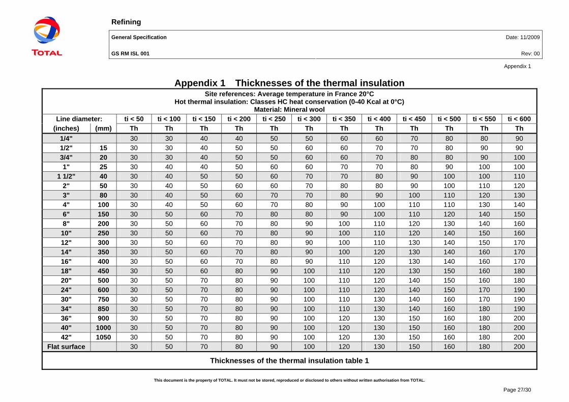
Refining General Specification Date: 11/2009
GS RM ISL 001 Rev: 00
Appendix 1
This document is the property of TOTAL. It must not be stored, reproduced or disclosed to others without written authorisation from TOTAL.
Page 27/30
Appendix 1 Thicknesses of the thermal insulation Site references: Average temperature in France 20°C
Hot thermal insulation: Classes HC heat conservation (0-40 Kcal at 0°C) Material: Mineral wool
Line diameter: ti < 50 ti < 100 ti < 150 ti < 200 ti < 250 ti < 300 ti < 350 ti < 400 ti < 450 ti < 500 ti < 550 ti < 600
(inches) (mm) Th Th Th Th Th Th Th Th Th Th Th Th
1/4" 30 30 40 40 50 50 60 60 70 80 80 90 1/2" 15 30 30 40 50 50 60 60 70 70 80 90 90 3/4" 20 30 30 40 50 50 60 60 70 80 80 90 100 1" 25 30 40 40 50 60 60 70 70 80 90 100 100
1 1/2" 40 30 40 50 50 60 70 70 80 90 100 100 110 2" 50 30 40 50 60 60 70 80 80 90 100 110 120 3" 80 30 40 50 60 70 70 80 90 100 110 120 130 4" 100 30 40 50 60 70 80 90 100 110 110 130 140 6" 150 30 50 60 70 80 80 90 100 110 120 140 150 8" 200 30 50 60 70 80 90 100 110 120 130 140 160 10" 250 30 50 60 70 80 90 100 110 120 140 150 160 12" 300 30 50 60 70 80 90 100 110 130 140 150 170 14" 350 30 50 60 70 80 90 100 120 130 140 160 170 16" 400 30 50 60 70 80 90 110 120 130 140 160 170 18" 450 30 50 60 80 90 100 110 120 130 150 160 180 20" 500 30 50 70 80 90 100 110 120 140 150 160 180 24" 600 30 50 70 80 90 100 110 120 140 150 170 190 30" 750 30 50 70 80 90 100 110 130 140 160 170 190 34" 850 30 50 70 80 90 100 110 130 140 160 180 190 36" 900 30 50 70 80 90 100 120 130 150 160 180 200 40" 1000 30 50 70 80 90 100 120 130 150 160 180 200 42" 1050 30 50 70 80 90 100 120 130 150 160 180 200
Flat surface 30 50 70 80 90 100 120 130 150 160 180 200
Thicknesses of the thermal insulation table 1

Refining General Specification Date: 11/2009
GS RM ISL 001 Rev: 00
Appendix 1
This document is the property of TOTAL. It must not be stored, reproduced or disclosed to others without written authorisation from TOTAL.
Page 28/30
Site references: Average temperature in France 20°C Hot thermal insulation: Classes HC heat conservation (0-40 Kcal at 0°C)
Material: Foam glass
Line diameter: ti < 50 ti < 100 ti < 150 ti < 200 ti < 250 ti < 300 ti < 350 ti < 400 ti < 450
(inches) (mm) Th Th Th Th Th Th Th Th Th
1/4" 25 40 50 60 60 70 70 80 90 1/2" 15 30 40 50 60 60 70 80 90 90 3/4" 20 30 50 50 60 70 70 80 90 90 1" 25 30 50 60 60 70 80 90 90 100
1 1/2" 40 40 50 60 70 80 80 90 100 110 2" 50 40 50 70 70 80 90 100 110 110 3" 80 40 60 70 80 90 90 110 120 120 4" 100 40 60 70 80 90 100 110 120 130 6" 150 40 60 80 90 100 110 120 130 140 8" 200 40 70 80 90 100 110 130 140 150 10" 250 50 70 80 100 110 120 130 150 150 12" 300 50 70 90 100 110 120 130 150 160 14" 350 50 70 90 100 110 120 140 150 160 16" 400 50 70 90 100 110 120 140 160 170 18" 450 50 70 90 100 120 130 140 160 170 20" 500 50 70 90 100 120 130 140 160 170 24" 600 50 70 90 110 120 130 150 170 180 30" 750 50 80 90 110 120 130 150 170 180 34" 850 50 80 100 110 120 140 150 170 180 36" 900 50 80 100 110 120 140 150 170 190 40" 1000 50 80 100 110 130 140 160 180 190 42" 1050 50 80 100 110 130 140 160 180 190
Flat surface 50 80 100 110 130 140 160 180 190
Thicknesses of the thermal insulation table 2

Refining General Specification Date: 11/2009
GS RM ISL 001 Rev: 00
Appendix 1
This document is the property of TOTAL. It must not be stored, reproduced or disclosed to others without written authorisation from TOTAL.
Page 29/30
Site references: Average temperature in France 20°C Hot thermal insulation: Classes PP personnel protection 70°C (0-40 Kcal at 0°C)
Material: Mineral wool Line diameter: ti < 100 ti < 150 ti < 200 ti < 250 ti < 300 ti < 350 ti < 400 ti < 450 ti < 500 ti < 550 ti < 600
(inches) (mm) Th Th Th Th Th Th Th Th Th Th Th
1/4" 30 30 30 30 30 30 40 40 50 60 60 1/2" 15 30 30 30 30 30 30 40 40 50 60 70 3/4" 20 30 30 30 30 30 30 40 50 50 60 70 1" 25 30 30 30 30 30 30 40 50 50 60 70
1 1/2" 40 30 30 30 30 30 40 40 50 60 70 80 2" 50 30 30 30 30 30 40 40 50 60 70 80 3" 80 30 30 30 30 30 40 50 60 70 80 90 4" 100 30 30 30 30 30 40 50 60 70 80 90 6" 150 30 30 30 30 30 40 50 60 70 90 100 8" 200 30 30 30 30 40 40 50 70 80 90 110 10" 250 30 30 30 30 40 50 60 70 80 90 110 12" 300 30 30 30 30 40 50 60 70 80 100 110 14" 350 30 30 30 30 40 50 60 70 80 100 110 16" 400 30 30 30 30 40 50 60 70 80 100 120 18" 450 30 30 30 30 40 50 60 70 80 100 120 20" 500 30 30 30 30 40 50 60 70 90 100 120 24" 600 30 30 30 30 40 50 60 70 90 100 120 30" 750 30 30 30 30 40 50 60 70 90 110 120 34" 850 30 30 30 30 40 50 60 70 90 110 130 36" 900 30 30 30 30 40 50 60 70 90 110 130 40" 1000 30 30 30 30 40 50 60 80 90 110 130 42" 1050 30 30 30 30 40 50 60 80 90 110 130
Flat surface 30 30 30 30 40 50 60 80 90 110 130
Thicknesses of the thermal insulation table 3
Refining General Specification Date: 11/2009
GS RM ISL 001 Rev: 00
Appendix 2
This document is the property of TOTAL. It must not be stored, reproduced or disclosed to others without written authorisation from TOTAL.
Page 30/30
Appendix 2 FRANCE
Harmlessness of the insulation
The insulation manufacturer shall supply a certificate of harmlessness certifying that its product is chemically neutral and presents no risk of corrosion to the support structures on which it is applied, or to any protective coating.
TOTAL Raffinaderij Antwerpen
Specification
- P -
Thermal and AcousticInsulation

Thermal and Acoustic Insulation
- P -
Rev. 329/04/2011
Total Raffinaderij Antwerpen 2/38
Revisie overzicht
Revisie Opmerking datum gewijzigde pagina’s
00 10/03/199701 Weather proofing for equipment 01/07/2004 5, 7, 9-13, 16-21, 22, 2602 06/10/2006 6,10,11,15,1603 Update for Cold Insulation 29/04/2011
Revision coding:Deleted items = strike trough.New or changed text = background shaded grey.Coding lasts only for present (one) revision.
Thermal and Acoustic Insulation
- P -
Rev. 329/04/2011
Total Raffinaderij Antwerpen 3/38
Inhoud
1. SCOPE...................................................................................................................................5
1.1. REFERENCES ...................................................................................................................51.2. DEFINITIONS.....................................................................................................................61.3. PIPING AND VESSELS ........................................................................................................6
2. INSULATION MATERIALS....................................................................................................6
2.1. GENERAL .........................................................................................................................62.2. BASE MATERIALS ..............................................................................................................72.3. WEATHER PROOFING MATERIALS ....................................................................................132.4. FASTENING MATERIALS AND ACCESSORY MATERIALS........................................................13
3. TABLES FOR NOMINAL INSULATION THICKNESSES ...................................................16
3.1. HOT INSULATION ............................................................................................................163.2. COLD INSULATION...........................................................................................................18
4. EXTENT OF INSULATION AND DESIGN DETAILS ..........................................................20
4.1. FOR HEAT CONSERVATION (CODED ON DOCUMENTS AS HC). ...........................................204.2. ITEMS NOT TO BE INSULATED FOR HEAT CONSERVATION, REGARDLESS OF TEMPERATURE,UNLESS SPECIFICALLY INDICATED OTHERWISE ON RELEVANT DOCUMENTS: ...................................204.3. PERSONNEL PROTECTION (CODED PP)............................................................................204.4. HEAT TRACED ITEMS ......................................................................................................214.5. TELL TALE HOLES IN REINFORCEMENT RINGS OR SUPPORTS SHALL BE FITTED WITH A SMALL
WEEP LINE TO THE OUTSIDE AND PROJECTING CLEAR OF THE INSULATION JACKETING TO DISPOSE OF
POSSIBLE OIL LEAKAGE FROM BEHIND THE WELDS. .......................................................................214.6. INSULATION AROUND PROTRUSIONS ................................................................................214.7. INSULATION ON PIPING AND EQUIPMENT NEAR FLANGES SHALL STOP SHORT AT A DISTANCE
EQUAL TO THE BOLT LENGTH PLUS 25 MM. ...................................................................................214.8. BARE AUSTENITIC STAINLESS STEEL SURFACES TO BE INSULATED SHALL FIRST BE WRAPPED
IN ALU-FOIL, ACTING AS BOTH BARRIER AND INHIBITOR AGAINST CORROSION. ................................224.9. BUNDLING OF STEAM LINES TO BURNERS (HEADERS AS WELL AS INDIVIDUAL LINES)TOGETHER WITH OTHER LINES IRRESPECTIVE OF SIZE IS NOT PERMITTED. .....................................224.10. HEAT EXCHANGER INSULATION DETAILS .......................................................................224.11. DETAILS VESSEL SUPPORTS ........................................................................................224.12. ACOUSTIC INSULATION ................................................................................................22
5. APPLICATION .....................................................................................................................23
5.1. GENERAL .......................................................................................................................235.2. SURFACE PREPARATION..................................................................................................245.3. HOT INSULATION.............................................................................................................245.4. COLD INSULATION...........................................................................................................27
6. ACOUSTIC INSULATION....................................................................................................33
6.1. GENERAL .......................................................................................................................336.2. CATEGORY A..................................................................................................................336.3. CATEGORY B..................................................................................................................336.4. CATEGORY C .................................................................................................................33
Thermal and Acoustic Insulation
- P -
Rev. 329/04/2011
Total Raffinaderij Antwerpen 4/38
7. QUALITY ASSURANCE AND INSPECTION ......................................................................34
1. LIST OF DRAWINGS .......................................................................................................352. INSULATION CHECKLIST...............................................................................................36
Thermal and Acoustic Insulation
- P -
Rev. 329/04/2011
Total Raffinaderij Antwerpen 5/38
1. Scope
This specification covers the minimum requirements for complete external insulation systems forhot, cold and acoustic services on surfaces of piping, equipment, instruments, etc.
This specification does not cover underground systems, internal insulation and insulation ofbuildings.
It is important to note that for new units this specification could be incomplete and does notcover all services. In this case licenser, TOTAL group and engineering contractor specifications(job specifications) shall be considered as well.
For revamp works original job specifications and licenser requirements shall be checked againstthis specification. In case of conflict the most severe prevails.
In case there are items not covered by this specification, the engineering company shall checkthe specifications of the TOTAL group, if the item is still not covered, the engineering companyshall spontaneously and at no cost submit its own specification for approval.
For deviations of the Total Raffinaderij Antwerpen (hereafter called TRA) Spec. "P" a waiverrequest shall be issued for approval to TRA Engineering Department. Only the head of TRAEngineering Department can approve deviations. Requests to change this specification shall bemade using the form DP-P003-F001.doc “aanvraag tot specificatie of standard wijziging”.
Remark:This specification is not restrictive. Modifications or alterations can be done after approval ofTotal Raffinaderij Antwerpen (TRA) Engineering Department.
1.1. References
Unless otherwise stated in the particular contractual conditions, all the referenced documents,and their addenda, are applicable in their latest revision.
A. Belgian NormsNBN S-21-203 Non-combustibility of insulation materials (combustible class A0)
B. AISI StandardsAISI 304 Specification for Stainless Steel
C. ASTM StandardsASTM A463 Specification for Aluminized Steel and PlateASTM B209M Specification for Aluminum Alloy Sheet and Plate (METRIC)ASTM B221M Specification for Aluminum Alloy ShapeASTM C167 Determination of Density of Thermal Insulating BlanketsASTM C177 Test Method for Steady State Heat Flux Measurements and Thermal
Transmission PropertiesASTM C302 Determination of Density of Preformed Pipe InsulationASTM C547 Specification for Mineral Fibre Preformed Pipe InsulationASTM C552 Specification for Cellular Glass Thermal InsulationASTM C592 Specification for Mineral Fibre Blanket Insulation, and Blanket Type Pipe
Insulation (Metal Mesh Covered)ASTM C795 Thermal insulation for use in contact with austenitic Stainless Steel
D. AGI Standard (Arbeits Gemeinschaft fuer Industrie)
Thermal and Acoustic Insulation
- P -
Rev. 329/04/2011
Total Raffinaderij Antwerpen 6/38
AGI Q 132 Determination of classification temperatures for fibrous insulationAGI Q 136 Determination of water absorption
E. Specification NWG 5 Acoustic Insulation of Pipes, Valves and Flanges, issued byEEMUA.DIN NormsDIN 7971 B German specification for screws.DIN 52612 Standard method for determination of heat transmission coefficient for
flat formsDIN 52613 Standard method for determination of heat transmission coefficient for
cylindrical forms
F. ISO NormsISO 8501 –1 Pictorial Standard For Surface PreparationISO 1182 Non-combustibility of materials
1.2. Definitions
The temperatures in this specification are to be read as normal operatingtemperatures unless specifically indicated otherwise.
Thermal conductivity of insulation base materials is expressed in W/mK at the givenmean temperature of the insulation.
Maximum permitted temperatures for fibrous insulation materials are meant to be theclassification temperatures as measured per AGI Q 132.
Nominal piping diameters including all appurtenances are stated as NPS, forexample a 12" line, as NPS12.
Vessels means process vessels. Total Raffinaderij Antwerpen (TRA) and/or principal or its representative is further
referred to as OWNER. Insulation contractor and/or any other performing insulation work is further referred to
as APPLICATOR. c.t.c. means center to center. VB means vapour barrier. PP means personnel protection. Jacketing means weather proofing metal sheeting constructed to a close fitting cover
of the base insulation. HC means heat conservation.
1.3. Piping and vessels
Piping above NPS 24 is to be insulated with same thickness and method as vessels. Vessels and equipment having a diameter of 24 inch and smaller shall be insulated
with same thickness and method as piping of that size.
2. Insulation materials
2.1. General
1. Asbestos and asbestos containing materials are not permitted.- For Lump Sum Contracts and for skid-mounted units the applicator shall -at completion-
certify in writing to owner that asbestos is not present in his work.- For jobs initiated by work orders asbestos free must be certified separately.
Thermal and Acoustic Insulation
- P -
Rev. 329/04/2011
Total Raffinaderij Antwerpen 7/38
2. Ceramic fibres may be hazardous to health.Where application for high heat service (> 700°C) is unavoidable, applicator is to requestfor permission with submittal of his health procedures.If permitted by owner, applicator shall duly register location and extent for futurereference. If permitted the fibres shall be have a Ø > 6 microns.
3. Zinc or zinc containing material shall not be used on or above stainless steel piping,vessels and equipment.
4. Insulation base material chloride content should meet de requirements of ASTM C795.
5. The water absorption, measured according AGI Q 136 shall be lower than 10 % byvolume.
6. Only one type wool is permitted on a job. Applicator shall indicate his choice already in hisbid.
7. Properties of supplied material shall not deviate more than 2 % from those specified inthis specification.
8. When economically attractive, applicator may propose in his quotation alternativeproducts, technically matching those specified here under, for acceptance by owner.
9. Materials shall be non-combustible according ISO 1182 and NBN S-21-203.
10. Insulation materials shall not produce smoke when materials are exposed to fire.
2.2. Base materials
2.2.1. Rock wool
2.2.1.1. Straight Pipe
Preformed rigid pipe sections made of resin bonded rock wool for services up till700°C and for max. NPS 24.- Thermal conductivity: 0.037 at 50°C; 0.043 at 100°C; 0.060 at 200°C; 0.083 at 300°C;
0.100 W/m2
at 400 °C and 0.180 W/m2
at 500 °C.- Density dependent on size and thickness: min. 100, max. 125 kg/m
3.
Density shall be conform ASTM C302.(The split between use of preformed sections and blankets may lay at another size ifeconomically more attractive, to be agreed upon by owner.)
Supplier TypeRock wool Lapinus 850Roclaine 345
2.2.1.2. Vessels and equipment, horizontal and vertical (optional large pipe sizes)
- Where horizontal insulation supports on vertical items are provided at each 2000 -2200 mm or less (ref. drawing DR190E000Z00000031):Blankets made of lightly resin-bonded rock wool stitched on galvanized or, forapplication on austenitic stainless steel items stainless steel wire mesh, mesh 25mm, suitable for services up to 700°C.
o Thermal conductivity: 0.038 at 50°C; 0.045 at 100°C; 0.066 at 200°C;0.095 at 300°C; 0.120 W/m
2at 400°C; 0.180 W/m
2at 500°C.
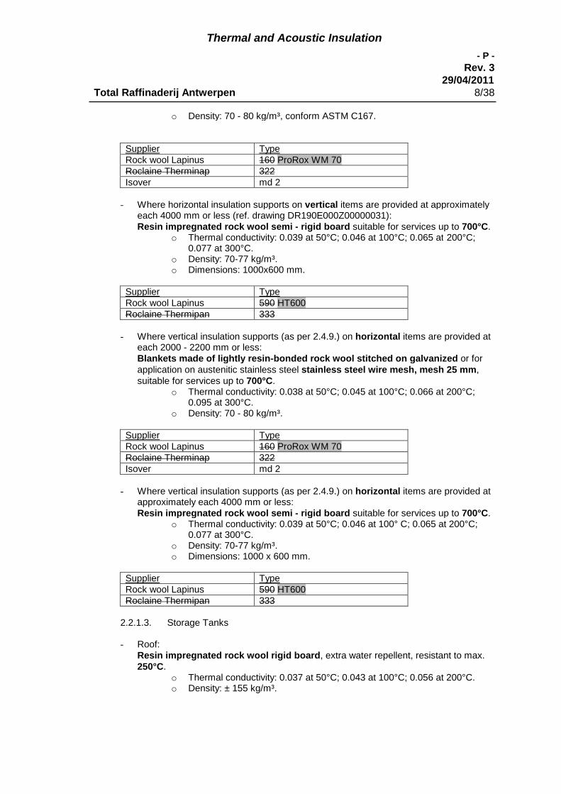
Thermal and Acoustic Insulation
- P -
Rev. 329/04/2011
Total Raffinaderij Antwerpen 8/38
o Density: 70 - 80 kg/m³, conform ASTM C167.
Supplier TypeRock wool Lapinus 160 ProRox WM 70Roclaine Therminap 322Isover md 2
- Where horizontal insulation supports on vertical items are provided at approximatelyeach 4000 mm or less (ref. drawing DR190E000Z00000031):Resin impregnated rock wool semi - rigid board suitable for services up to 700°C.
o Thermal conductivity: 0.039 at 50°C; 0.046 at 100°C; 0.065 at 200°C;0.077 at 300°C.
o Density: 70-77 kg/m³.o Dimensions: 1000x600 mm.
Supplier TypeRock wool Lapinus 590 HT600Roclaine Thermipan 333
- Where vertical insulation supports (as per 2.4.9.) on horizontal items are provided ateach 2000 - 2200 mm or less:Blankets made of lightly resin-bonded rock wool stitched on galvanized or forapplication on austenitic stainless steel stainless steel wire mesh, mesh 25 mm,suitable for services up to 700°C.
o Thermal conductivity: 0.038 at 50°C; 0.045 at 100°C; 0.066 at 200°C;0.095 at 300°C.
o Density: 70 - 80 kg/m³.
Supplier TypeRock wool Lapinus 160 ProRox WM 70Roclaine Therminap 322Isover md 2
- Where vertical insulation supports (as per 2.4.9.) on horizontal items are provided atapproximately each 4000 mm or less:Resin impregnated rock wool semi - rigid board suitable for services up to 700°C.
o Thermal conductivity: 0.039 at 50°C; 0.046 at 100° C; 0.065 at 200°C;0.077 at 300°C.
o Density: 70-77 kg/m³.o Dimensions: 1000 x 600 mm.
Supplier TypeRock wool Lapinus 590 HT600Roclaine Thermipan 333
2.2.1.3. Storage Tanks
- Roof:Resin impregnated rock wool rigid board, extra water repellent, resistant to max.250°C.
o Thermal conductivity: 0.037 at 50°C; 0.043 at 100°C; 0.056 at 200°C.o Density: ± 155 kg/m³.

Thermal and Acoustic Insulation
- P -
Rev. 329/04/2011
Total Raffinaderij Antwerpen 9/38
Supplier TypeRock wool Lapinus 523 CRSIsover Thermipan 313
- Shell:Resin impregnated rock wool flexible board, resistant to max. 250°C.
o Thermal conductivity: 0.044 at 50°C; 0.055 at 100°C; 0.080 at 200°C.o Density: ± 40 kg/m³.
Supplier TypeRock wool Lapinus 590 HT600Thermipan 313
2.2.2. Glass wool
2.2.2.1. Straight pipe
Preformed rigid pipe sections made of resin bonded glass fibre for services up till400°C and for max. NPS 24.
o Thermal conductivity: 0.035 at 50°C; 0.041 at 100°C; 0.059 at 200°C.o Density: 65 - 90 kg/m3 depending on NPS and thickness.
(Note: The split between use of preformed sections or blankets may lay at another size ifeconomic more attractive, to be agreed upon by owner.)
Supplier TypeIsover For bores up to 57 mm type IS-HI
For bores 61 mm and above type IS-I
2.2.2.2. Vessels and equipment, horizontal and vertical (optional large pipe sizes)
- Where horizontal insulation supports on vertical items are provided at each 2000 -2200 mm or less (ref. drawing DR190E000Z00000031):Blankets made of non-bonded glass fibre stitched on galvanized or forapplication on austenitic stainless steel items stainless steel wire mesh, mesh 25mm, suitable for services up to 500°C.
o Thermal conductivity: 0.036 at 50°C; 0.044 at 100°C; 0.063 at 200°C;0.075 at 250°C
o Density: ± 55 kg/m³
Supplier TypeIsover Telisol 704
- Where horizontal insulation supports are provided on vertical items at approximatelyeach 4000 mm or less (ref. drawing DR190E000Z00000031):Resin impregnated glass fibre semi - rigid board suitable for services up to 350°C.
o Thermal conductivity: 0.037 at 50°C; 0.044 at 100°C; 0.067 at 200°C;0.078 at 250°C
o Density: ± 35 kg/m³o Dimensions: 1350 x 600 mm
Supplier Type
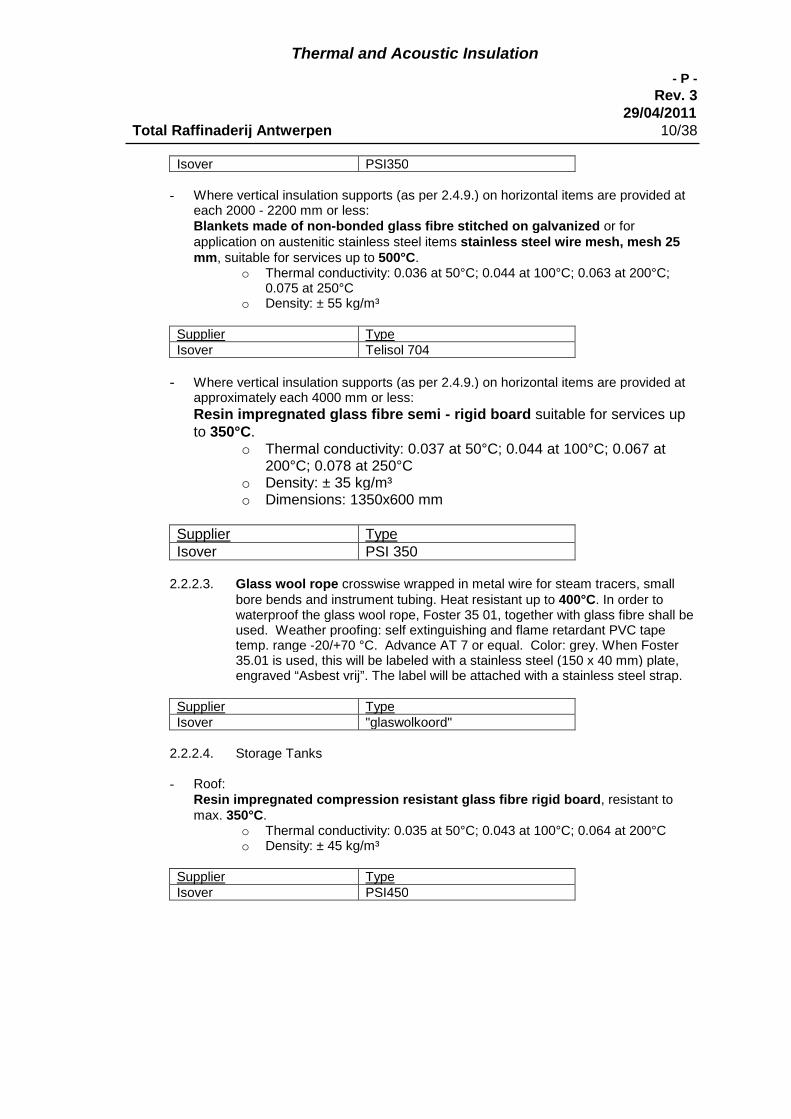
Thermal and Acoustic Insulation
- P -
Rev. 329/04/2011
Total Raffinaderij Antwerpen 10/38
Isover PSI350
- Where vertical insulation supports (as per 2.4.9.) on horizontal items are provided ateach 2000 - 2200 mm or less:Blankets made of non-bonded glass fibre stitched on galvanized or forapplication on austenitic stainless steel items stainless steel wire mesh, mesh 25mm, suitable for services up to 500°C.
o Thermal conductivity: 0.036 at 50°C; 0.044 at 100°C; 0.063 at 200°C;0.075 at 250°C
o Density: ± 55 kg/m³
Supplier TypeIsover Telisol 704
- Where vertical insulation supports (as per 2.4.9.) on horizontal items are provided atapproximately each 4000 mm or less:
Resin impregnated glass fibre semi - rigid board suitable for services upto 350°C.
o Thermal conductivity: 0.037 at 50°C; 0.044 at 100°C; 0.067 at200°C; 0.078 at 250°C
o Density: ± 35 kg/m³o Dimensions: 1350x600 mm
Supplier TypeIsover PSI 350
2.2.2.3. Glass wool rope crosswise wrapped in metal wire for steam tracers, smallbore bends and instrument tubing. Heat resistant up to 400°C. In order towaterproof the glass wool rope, Foster 35 01, together with glass fibre shall beused. Weather proofing: self extinguishing and flame retardant PVC tapetemp. range -20/+70 °C. Advance AT 7 or equal. Color: grey. When Foster35.01 is used, this will be labeled with a stainless steel (150 x 40 mm) plate,engraved “Asbest vrij”. The label will be attached with a stainless steel strap.
Supplier TypeIsover "glaswolkoord"
2.2.2.4. Storage Tanks
- Roof:Resin impregnated compression resistant glass fibre rigid board, resistant tomax. 350°C.
o Thermal conductivity: 0.035 at 50°C; 0.043 at 100°C; 0.064 at 200°Co Density: ± 45 kg/m³
Supplier TypeIsover PSI450
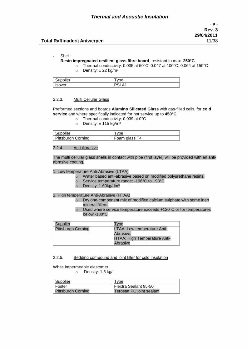
Thermal and Acoustic Insulation
- P -
Rev. 329/04/2011
Total Raffinaderij Antwerpen 11/38
- Shell:Resin impregnated resilient glass fibre board, resistant to max. 250°C.
o Thermal conductivity: 0.035 at 50°C; 0.047 at 100°C; 0.064 at 150°Co Density: ± 22 kg/m³
Supplier TypeIsover PSI A1
2.2.3. Multi Cellular Glass
Preformed sections and boards Alumino Silicated Glass with gas-filled cells, for coldservice and where specifically indicated for hot service up to 450°C.
o Thermal conductivity: 0.039 at 0°Co Density: ± 115 kg/m³
Supplier TypePittsburgh Corning Foam glass T4
2.2.4. Anti Abrasive
The multi cellular glass shells in contact with pipe (first layer) will be provided with an anti-abrasive coating.
1. Low temperature Anti-Abrasive (LTAA)o Water based anti-abrasive based on modified polyurethane resins.o Service temperature range: -196°C to +93°Co Density: 1.60kg/dm³
2. High temperature Anti-Abrasive (HTAA)o Dry one-component mix of modified calcium sulphate with some inert
mineral fillers.o Used where service temperature exceeds +120°C or for temperatures
below -180°C
Supplier TypePittsburgh Corning LTAA: Low temperature Anti-
Abrasive.HTAA: High Temperature Anti-Abrasive
2.2.5. Bedding compound and joint filler for cold insulation
White impermeable elastomer.o Density: 1.5 kg/I
Supplier TypeFosterPittsburgh Corning
Flextra Sealant 95-50Terostat PC joint sealant

Thermal and Acoustic Insulation
- P -
Rev. 329/04/2011
Total Raffinaderij Antwerpen 12/38
2.2.6. Vapour barrier mastic for cold insulation
Elastomer on water basis.First coat grey, second coat white.
o Density: 1.4 kg/I
Supplier (Fabricate) TypeFoster 30-91 81/91 vapor safe grey,
30-90 81/81 vapor safe white
Alternatively, the multi cellular glass shells may be bought with a factory applied VaporBarrier.
Supplier (Fabricate) TypePittsburgh Corning Terostat PC Factory Applied on
Foam Glass T4
2.2.7. Armaflex
- A closed cell, fibre-free elastomeric foam insulation.
o Max operating temperature: -196°C to +125°Co Density 60-70 kg/m³
Supplier (Fabricate) TypeArmacell Armaflex LTD
o Max operating temperature: -50°C to +105°Co Density 40-60 kg/m³
Supplier (Fabricate) TypeArmacell AF/Armaflex and Armaflex LT
2.2.8. Vapour barrier reinforcing glass fibre cloth
Open weave glass cloth with acryl finish, mesh 3-4 mm, 250 gr/m2.
2.2.9. Insulation cement
Insulation cement shall be rock wool based heat resisting cement, for restricted useafter approval of owner and only where heat curing at the time of application is available.
2.2.10. Anti-vibration seals
2.2.10.1. Up to 120°C Synthetic rubber.Supplier: Hertel Belgium, Wijnegem.
2.2.10.2. Above 120°C Non-flammable high density felt. 5 mm thick.Supplier for Benelux: Stokvis & Smits b.v. Umuiden, NL, Type VILTON 30

Thermal and Acoustic Insulation
- P -
Rev. 329/04/2011
Total Raffinaderij Antwerpen 13/38
2.3. Weather proofing materials
2.3.1. Metal sheeting
2.3.1.1. Acoustic insulation, categories B and C, and all thermal insulation ofequipment (on- and off-site) and on site piping:Flat Aluminized Steel sheeting Type Armco 2, ASTM A463, type 2Thickness: NPS 24 and smaller: 0.6 mm, above NPS 24, vessels andequipment: 0.8 mm.
2.3.1.2. Off-site piping (= outside unit Battery Limit) and off-site storage tanks:Flat Aluminum sheeting, ASTM B209M alloy 3003, temper H 14 (half hard)Thickness:
NPS 2 and smaller 0.6 mmNPS 3 thru 8 0.8 mmNPS 10 and above 1 mm
2.3.1.3. If technical or economical justified: Stainless steel sheet, ASTM A-167 Type304. Thickness NPS 24 and smaller: 0,6 mm, above NPS 24, vessels andequipment: 0,8 mm.
2.3.2. Perforated sheeting for personnel protection:ASTM B209M, alloy 3003, temper H14, 1 mm thick, 60% open.
2.3.3. Expanded metal lath for open cages for personnel protection shall begalvanized or stainless steel, 1 mm thick, (see DR190E000Z000 00029) (inDutch language: "Strekmetaal").
2.4. Fastening materials and accessory materials
2.4.1. GeneralFor stainless steel items Only stainless steel fastening materials andaccessory materials are permitted to fasten the metal sheets.
2.4.2. To fasten Insulation:
Hot Insulation Cold InsulationDiam. Type fastener Diam. Type fastener
< 24”Galvanized orSS Wire 1mm
< 6” Tape
≥ 24” – < 60”SS StrappingBand 12,5 x 0,5mm
≥ 6 - ≤ 24”SS Strapping Band12,5 x 0,5 mm
≥ 60”SS StrappingBand 20 x 0,5 mm
> 24”SS Strapping Band20 x 0,5 mm
2.4.2. For NPS 24 or smaller, over base insulation for hot service, spaced at 300 mmGalvanized binding wire, 1 mm,Stainless steel AISI 304 wire 1 mm
2.4.3. For NPS 12 or smaller over base insulation in cold service and for above NPS24 and vessels and equipment with dia. up to 60 inch, over base insulation hot

Thermal and Acoustic Insulation
- P -
Rev. 329/04/2011
Total Raffinaderij Antwerpen 14/38
service, spaced at 300 mm and over weather proofing metal sheets whererequired (e.g. at expansion joints and cold insulation) and for strappingclamped supports as per drawing DR190E000Z00000021:Galvanized strapping bands and seals 12.5 mm (1/2") x 0.5 mm*,Stainless steel strapping bands and seals 12.5 mm x 0.5 mm*.(* For cold service at outside dia. of insulation larger than 1m
10.6 or 0.8 mm
thickness)
2.4.4. For sizes above 60 inch spaced at 300 mm over both base insulation andmetal sheeting, in combination with screws (cold service no screws) as peritem 2.C 4.7:Galvanized strapping bands and seals 20 mm (3/4") x 0.5 mm*,Stainless steel strapping bands and seals 20 mm x 0.5 mm*.(* For cold service at outside dia. of insulation larger than 1m
10.6 or 0.8 mm
thickness)
2.4.3. Breather springs for use in strapping bands vessels and equipment atdiameter's over 3000 mm and above 250°C shall be made of stainless steel,supplier Gerard. Note: Corrugated strips are not permitted.
2.4.4. Blanket hooksGalvanized wire 1.6 mm or Stainless steel wire 1.6 mm, at each 150 mm or atshorter distances where required to prevent gaps.
2.4.5. ScrewsIn hot insulation:For aluminium sheeting: hard aluminium,For stainless steel sheeting: only stainless steel fastening materials should beused.
- For fastening of metal sheeting to supports, distance clips, etc.Hard aluminium or stainless steel, hexagonal head with fixed ring lined atthe underside with vulcanized neoprene, 6.25 x 19 mm, type B, to beapplied at each 150 mm center to center.
- For fastening of metal sheeting to metal sheetingHard aluminium or stainless steel, cylindrical slotted head ST 4,8B (10 X1/2) DIN 7971 B.
2.4.6 Pop NailsOnly stainless steel popnails will be used to fasten metal sheeting in coldinsulation.Metal sheeting on horizontal/vertical pieces of pipe will be fastened with metalstrips. On bends they will be fastened with popnails. In order to do this, anextra layer of bubble wrap (10mm) will be applied between sheeting andvapour barrier to protect the vapour barrier.
2.4.7. Quick release togglesFor removable covers NPS 12 and above and equipment:Stainless steel, type CAMLOC V951I02-1-BP or approved equivalent.
2.4.8. Steel Insulation Supports
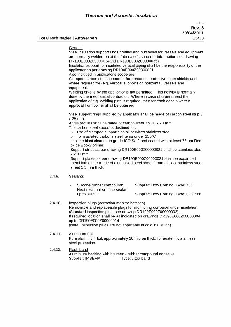
Thermal and Acoustic Insulation
- P -
Rev. 329/04/2011
Total Raffinaderij Antwerpen 15/38
GeneralSteel insulation support rings/profiles and nuts/eyes for vessels and equipmentare normally welded-on at the fabricator's shop (for information see drawingDR190E000Z00000034and DR190E000Z00000035).Insulation support for insulated vertical piping shall be the responsibility of theapplicator as per drawing DR190E000Z00000021.Also included in applicator's scope are:Clamped carbon steel supports - for personnel protective open shields andwhere required for (e.g. vertical supports on horizontal) vessels andequipment.Welding on-site by the applicator is not permitted. This activity is normallydone by the mechanical contractor. Where in case of urgent need theapplication of e.g. welding pins is required, then for each case a writtenapproval from owner shall be obtained.
Steel support rings supplied by applicator shall be made of carbon steel strip 3x 25 mm.Angle profiles shall be made of carbon steel 3 x 20 x 20 mm.The carbon steel supports destined for:o use of clamped supports on all services stainless steel,o for insulated carbons steel items under 150°Cshall be blast cleaned to grade ISO Sa 2 and coated with at least 75 µm Redoxide Epoxy primer.Support strips as per drawing DR190E000Z00000021 shall be stainless steel2 x 30 mm.Support plates as per drawing DR190E000Z00000021 shall be expandedmetal lath either made of aluminized steel sheet 2 mm thick or stainless steelsheet 1.5 mm thick.
2.4.9. Sealants
- Silicone rubber compound: Supplier: Dow Corning, Type: 781- Heat resistant silicone sealant
up to 300°C: Supplier: Dow Corning, Type: Q3-1566
2.4.10. Inspection plugs (corrosion monitor hatches)Removable and replaceable plugs for monitoring corrosion under insulation:(Standard inspection plug: see drawing DR190E000Z00000002).If required location shall be as indicated on drawings DR190E000Z00000004up to DR190E000Z00000014.(Note: Inspection plugs are not applicable at cold insulation)
2.4.11. Aluminum FoilPure aluminium foil, approximately 30 micron thick, for austenitic stainlesssteel protection.
2.4.12. Flash bandAluminium backing with bitumen - rubber compound adhesive.Supplier: IMBEMA Type: Jittra band
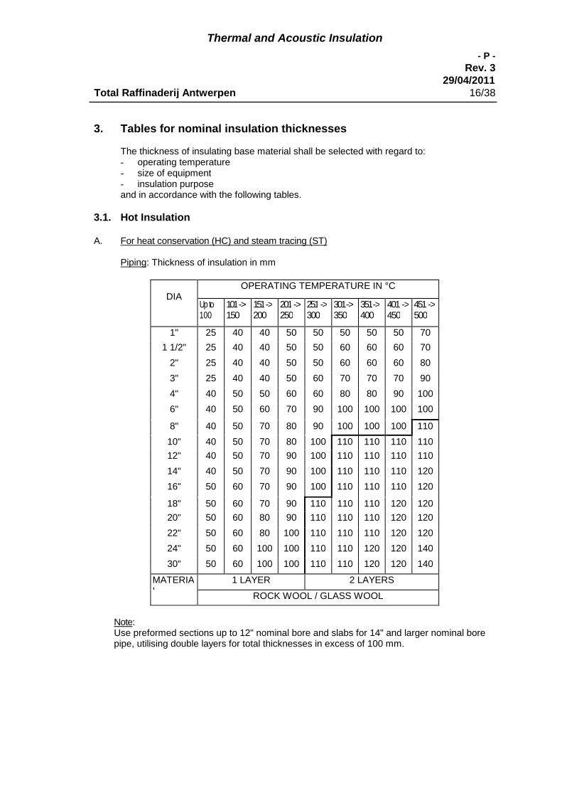
Thermal and Acoustic Insulation
- P -
Rev. 329/04/2011
Total Raffinaderij Antwerpen 16/38
3. Tables for nominal insulation thicknesses
The thickness of insulating base material shall be selected with regard to:- operating temperature- size of equipment- insulation purposeand in accordance with the following tables.
3.1. Hot Insulation
A. For heat conservation (HC) and steam tracing (ST)
Piping: Thickness of insulation in mm
DIAOPERATING TEMPERATURE IN °C
Up to100
101->150
151->200
201->250
251->300
301->350
351->400
401 ->450
451->500
1" 25 40 40 50 50 50 50 50 70
1 1/2" 25 40 40 50 50 60 60 60 70
2" 25 40 40 50 50 60 60 60 80
3" 25 40 40 50 60 70 70 70 90
4" 40 50 50 60 60 80 80 90 100
6" 40 50 60 70 90 100 100 100 100
8" 40 50 70 80 90 100 100 100 110
10" 40 50 70 80 100 110 110 110 110
12" 40 50 70 90 100 110 110 110 110
14" 40 50 70 90 100 110 110 110 120
16" 50 60 70 90 100 110 110 110 120
18" 50 60 70 90 110 110 110 120 120
20" 50 60 80 90 110 110 110 120 120
22" 50 60 80 100 110 110 110 120 120
24" 50 60 100 100 110 110 120 120 140
30" 50 60 100 100 110 110 120 120 140
MATERIAL
1 LAYER 2 LAYERS
ROCK WOOL / GLASS WOOL
Note:Use preformed sections up to 12" nominal bore and slabs for 14" and larger nominal borepipe, utilising double layers for total thicknesses in excess of 100 mm.
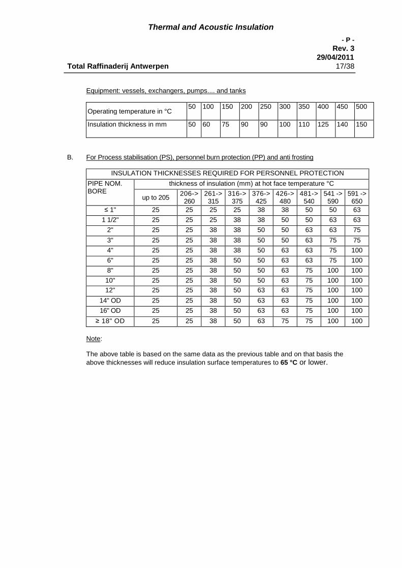
Thermal and Acoustic Insulation
- P -
Rev. 329/04/2011
Total Raffinaderij Antwerpen 17/38
Equipment: vessels, exchangers, pumps.... and tanks
Operating temperature in °C50 100 150 200 250 300 350 400 450 500
Insulation thickness in mm 50 60 75 90 90 100 110 125 140 150
B. For Process stabilisation (PS), personnel burn protection (PP) and anti frosting
INSULATION THICKNESSES REQUIRED FOR PERSONNEL PROTECTION
PIPE NOM.BORE
thickness of insulation (mm) at hot face temperature °C
up to 205206->
260261->315
316->375
376->425
426->480
481->540
541 ->590
591 ->650
≤ 1" 25 25 25 25 38 38 50 50 63
1 1/2" 25 25 25 38 38 50 50 63 63
2" 25 25 38 38 50 50 63 63 75
3" 25 25 38 38 50 50 63 75 75
4" 25 25 38 38 50 63 63 75 100
6" 25 25 38 50 50 63 63 75 100
8" 25 25 38 50 50 63 75 100 100
10" 25 25 38 50 50 63 75 100 100
12" 25 25 38 50 63 63 75 100 100
14" OD 25 25 38 50 63 63 75 100 100
16" OD 25 25 38 50 63 63 75 100 100
≥ 18" OD 25 25 38 50 63 75 75 100 100
Note:
The above table is based on the same data as the previous table and on that basis the
above thicknesses will reduce insulation surface temperatures to 65 °C or lower.

Thermal and Acoustic Insulation
- P -
Rev. 329/04/2011
Total Raffinaderij Antwerpen 18/38
3.2. Cold Insulation
A. For cold conservation (CC) / Condensation Control
Thickness Foamglass
Temp.+18°C to -110°C
NOMINAL
PIPE
SIZE
NORMAL OPERATING TEMPERATURE
°C THRU °C
18 9 0 -11 -21 -31 -41 -51 -61 -71 -81 -91 -10110 0 -10 -20 -30 -40 -50 -60 -70 -80 -90 -100 -110
1 30 30 30 40 50 60 60 70 80 80 90 90 1001 ½ 30 30 30 40 50 60 70 80 80 90 100 100 100
2 30 30 30 40 50 60 70 80 90 90 100 110 120
3 30 30 30 50 60 70 80 90 90 100 110 120 1204 30 30 40 50 60 70 80 90 100 110 110 120 130
6 30 30 40 50 60 80 90 100 110 120 120 130 1408 30 30 40 50 70 80 90 100 110 120 130 140 150
10 30 30 40 50 70 80 90 110 120 130 140 140 150
12 30 30 40 60 70 80 100 110 120 130 140 150 16014 30 30 40 60 70 80 100 110 120 130 140 150 16016 30 30 40 60 70 90 100 110 120 130 140 150 16018 30 30 40 60 70 90 100 110 120 140 150 160 17020 30 30 40 60 70 90 100 110 130 140 150 160 170
22 30 30 40 60 70 90 100 120 130 140 150 160 17024 30 30 40 60 70 90 100 120 130 140 150 160 17028 30 30 40 60 70 90 100 120 130 140 150 160 17032 30 30 40 60 70 90 100 120 130 140 150 160 17036 50 50 50 60 80 90 110 120 130 150 160 170 180
1 LAYER 2 LAYERS 3 LAYERS
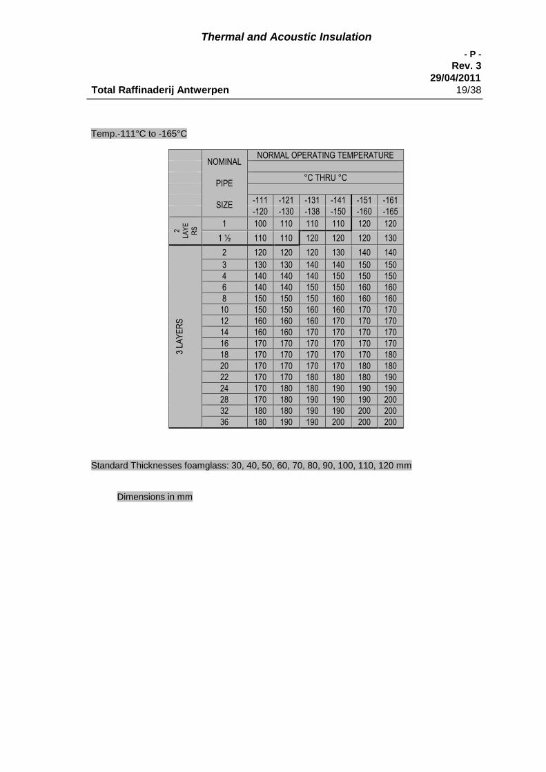
Thermal and Acoustic Insulation
- P -
Rev. 329/04/2011
Total Raffinaderij Antwerpen 19/38
Temp.-111°C to -165°C
NOMINAL
PIPE
SIZE
NORMAL OPERATING TEMPERATURE
°C THRU °C
-111 -121 -131 -141 -151 -161-120 -130 -138 -150 -160 -165
2LA
YE
RS
1 100 110 110 110 120 120
1 ½ 110 110 120 120 120 130
3LA
YE
RS
2 120 120 120 130 140 140
3 130 130 140 140 150 1504 140 140 140 150 150 1506 140 140 150 150 160 1608 150 150 150 160 160 160
10 150 150 160 160 170 17012 160 160 160 170 170 17014 160 160 170 170 170 17016 170 170 170 170 170 17018 170 170 170 170 170 18020 170 170 170 170 180 18022 170 170 180 180 180 19024 170 180 180 190 190 19028 170 180 190 190 190 20032 180 180 190 190 200 20036 180 190 190 200 200 200
Standard Thicknesses foamglass: 30, 40, 50, 60, 70, 80, 90, 100, 110, 120 mm
Dimensions in mm

Thermal and Acoustic Insulation
- P -
Rev. 329/04/2011
Total Raffinaderij Antwerpen 20/38
B. For heat/Cold conservation (HC) / Condensation Control (Normal operating temperaturefrom 18°C thru -20°C with high temperature cycles to 250°C)
For Cyclic Serve application, the line expansion will have to be calculated in order to determinewhich shells will be used, how the shells will be placed, and the location of joints.In order to do this properly, the original jobspec must be consulted
4. Extent of insulation and design details
4.1. For Heat Conservation (coded on documents as HC).The following items shall receive insulation for heat conservation only when above 120°C,unless specifically indicated otherwise on the relevant documents:- Process piping, except valves and flanges.- Steam piping 40 bar and lower, including valves and flanges.- Equipment, including vessels, steam turbines and steam engines.- Heat traced items including valves and flanges and tracer jumpers.
(Note: when in hazardous service or a service above self ignition temperature, e.g.hydrogen service, valves and flanges shall be left free of insulation.)
- Piping with the following services shall have the valves and flanges insulated withremovable boxes: Pitch, hot oil (bitumen), sulphur and superheated steam, exceptwhere explicitly indicated otherwise.Hot oil valves will be insulated where possible to minimize heatloss.
4.2. Items NOT to be insulated for heat conservation, regardless of temperature,unless specifically indicated otherwise on relevant documents:- Piping and equipment where it is desirable to lose heat and indicated as such on the
relevant documents.- Pumps and compressors.- Valves and flanges in steam service when above 40 bar and in process piping
systems.- Valves and flanges in hydrogen and hazardous service, except valves, flanges and
bellows in H2S rich gas lines at sulphur plants (ARDS -jobs 57/58) (to preventcondensation).
- Manholes, handholes (in view of leak detection).- Main flanges and bolts of heat exchangers and girth flanges of heat exchangers and
other equipment.- Piping and equipment operating intermittent, such as relief valves, vents, drains,
steam-out, snuffing steam and decoking systems, blow-down systems, flare systemand the by-pass of heat exchangers.
- Piping and equipment supports extending outside the insulation thickness of the item.- Expansion joints (e.g. bellows), hinge joints, line filters and line mixers.
(Note: This instruction does NOT include insulation expansion joints).- Fuel gas and pilot gas lines to individual burners (headers excluded).- Instrument air lines.- Name plates.
4.3. Personnel Protection (coded PP)
4.3.1. GeneralPersonnel protection shall normally be achieved by application of open shieldsand/or cages (see drawing DR190E000Z00000029).All surfaces indicated for PP shall be coated as for exposure to atmosphere by
Thermal and Acoustic Insulation
- P -
Rev. 329/04/2011
Total Raffinaderij Antwerpen 21/38
others.Surfaces where PP is required by means of a thermal insulation system shallbe clearly indicated as such on the relevant documents. The outer surface ofthe insulation shall not exceed 65 °C.
4.3.2. The distance of the open shields to the hot surface shall be as per thethickness table for PP-insulation.
4.3.3. PP shall be applied where the hot surfaces are above 65° C and when lessthan 600 mm from normal working areas, walkways, etc., with risk to beaccidentally contacted by operating personnel, in every working area, walkway,… and on ground level.
4.3.4. Extent shall be horizontally 600 mm to both sides and vertically 2000 mmupwards from floor.
4.4. Heat Traced items
4.4.1. GeneralTraced surfaces with their tracers shall be insulated, inclusive valves andflanges, except as outlined in item 4.1. of this chapter.Jumpers shall also be insulated, unless specifically indicated otherwise. See §5.3.5. Selection of the insulation thickness shall be according the NPS or dia.and the temperature of the traced item as per the insulation thickness table forheat conservation.
4.4.2. Jacketed lines and electrical traced items including drinking-water lines.Application shall be same as for non-traced items.
4.4.3. Steam traced lines shall be insulated according drawingDR190E000Z00000025.
4.4.4. Electrical traced lines shall be provided with stickers, size approximately 8 x 24cm, yellow background, white lettering with legend: " ELECTRICAL TRACED",each 10 m, facing walkways and personnel areas.
4.5. Tell tale holes in reinforcement rings or supports shall be fitted with a small weep line tothe outside and projecting clear of the insulation jacketing to dispose of possible oilleakage from behind the welds.
4.6. Insulation around protrusionsThe area around nozzles, man and handholes, vents and drains shall be kept free offibrous insulation to a distance of the outer circumference of the nozzle flange plus 25 mmor when no flange to a distance of 25 mm, except at vertical protrusions with welded-onshields, where fibrous insulation shall fit close to the protrusion. See also item 5.1.7. withfigure.
4.7. Insulation on piping and equipment near flanges shall stop short at a distanceequal to the bolt length plus 25 mm.End caps and sealant are to be provided to prevent ingress of moisture.

Thermal and Acoustic Insulation
- P -
Rev. 329/04/2011
Total Raffinaderij Antwerpen 22/38
4.8. Bare Austenitic stainless steel surfaces to be insulated shall first be wrapped inalu-foil, acting as both barrier and inhibitor against corrosion.
4.9. Bundling of steam lines to burners (headers as well as individual lines) together with otherlines irrespective of size is not permitted.Fuel oil lines shall be steam traced and insulated separately.
4.10. Heat exchanger insulation details
4.10.1. Shell and tube type- Shell and tubes up to and including 12" diameter, to be insulated with
preformed pipe sections, above 12" diameter with board type insulation.- Shell cover: Insulate the curved head but not the flange of the cover.- Channel: No insulation on channel flanges and bolts.- Channel cover: Insulate only the part within the bolts circle, leaving the
bolts and outer edge free of insulation.- Integral channel: Insulate as shell cover.- For frequently opened heat exchangers, removable parts will be foreseen:
see DR190E000Z0000061.
4.10.2. Double pipe typePreformed pipe sections to be applied on top of the upper tube and at theunderside of the lower tube.Board of the same thickness as the pipe sections shall be placed in the spacebetween the upper and lower pipe sections and the entire assembly shall beduly strapped without gaps or open joints.Head and return bend shall be insulated with blankets, close fitting, with thewire mesh laced and banded.
4.11. Details vessel supportsSee drawings DR190E000Z00000031, DR190E000Z00000032 andDR190E000Z00000035.
4.12. Acoustic insulation
4.12.1. Noise reduction per category.Acoustic insulation consists of 3 categories according specification NWG5,viz.:- Category A, light noise reduction- Category B, medium noise reduction- Category C, heavy noise reduction
The following table contains theoretical values for calculation purposes only.
CATEGORY NOISE REDUCTION IN dB WITHIN THE OCTAVE BAND WITH THE MIDDLEFREQUENCY (Hz)
63 125 250 500 1000 2000 4000 8000
A - - - 5 10 15 20 25
B - - 5 15 20 25 30 35

Thermal and Acoustic Insulation
- P -
Rev. 329/04/2011
Total Raffinaderij Antwerpen 23/38
C - 5 15 25 30 35 40 45
See further chapter 6.
5. Application
5.1. General
5.1.1. All insulation material shall be kept dry at storage, handling, during and afterapplication. Fibrous insulation material that has been wet shall be discarded.
5.1.2. Where the required nominal insulation thickness cannot be reached withcommercial available standard thicknesses more layers shall have to beapplied with all joints staggered.
5.1.3. Unavoidable gaps and voids at hot insulation shall be stuffed firmly with loosewool. For this purpose cut-offs of blankets may be used.
5.1.4. The insulation shall withstand the windload, inclusive the negative windload atthe off wind side as may occur on site. If so required by owner, applicator shallsubmit his calculations for windload resistance to owner (for information only:Prevailing wind direction: WSW, strength: permanent up to 90 km/h, peaks135 km/h).
5.1.5. Expansion joints shall be required at temperatures above 200°C at lengths of6 m, and further each 6 m both horizontally and vertically.
5.1.6. Stiffener rings at vessels shall be kept free of insulation at the area betweenflange and shell; if required the applicator shall provide an aluminum U -profile, bottom up, on the stiffener ring. See drawing DR190E000Z00000030.
5.1.7. Around nozzles, hand and manholes, etc. an area as per item 4.6. shall bekept free of fibrous insulation. A removable ring of 2 or more sections of multicellular glass, thickness same as adjacent insulation, fitting the gap, shall beinstalled. See figure below.

Thermal and Acoustic Insulation
- P -
Rev. 329/04/2011
Total Raffinaderij Antwerpen 24/38
Vessel
Fibrous Insulation
Multi-cellular Glass
Diameter Flange+ 50 mm
Shield
Metal Sheeting
Removable insulation at nozzle
5.1.8. Bottoms of vertical vessels, including those inside skirts shall be insulated asper this specification and according drawing 13 "details of insulated vessel".
5.2. Surface preparation
All surfaces shall be dry prior to insulation. Piping and equipment to be insulated, and operatingbelow 150°C, has been painted by others. If not painted or if coating has been damaged, thenapplicator shall inform owner and postpone insulation work till instructions.Painted and unpainted surfaces shall be thoroughly cleaned from all foreign matter. Oil andgrease shall be removed with solvents or degreasing agents.The surface and the material used should be dry before and during application and shouldremain so until startup. Hydrostatic, radiographic and other test should be completed beforestarting the insulation.Stainless steel piping and equipment or carbon steel piping and equipment above 150°C havenot been painted. Good adhering temporary coats are not to be removed. Loose rust and millscale, where present, shall be removed.
5.3. Hot insulation
5.3.1. Pipe insulation supports on vertical piping shall be installed by applicator asper drawing DR190E000Z00000021.
5.3.2. Preformed pipe sectionsSections shall be fitted snugly together and to the surface with no voids or gaps.Longitudinal joints staggered. Elbows shall be mitered with binding wire or bandaround each miter.See drawing DR190E000Z00000020.
5.3.3. BoardBoard shall be bent to fit the curvature of the item, where required to avoidopen joints, the sides shall be bevelled. At large surfaces the boards shall beapplied in brick bond fashion. Strapping bands shall be applied at 300 mmc.t.c.
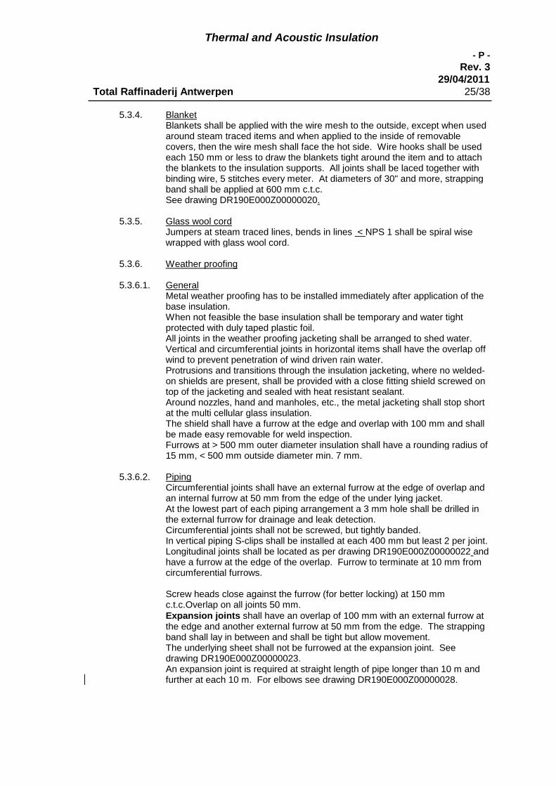
Thermal and Acoustic Insulation
- P -
Rev. 329/04/2011
Total Raffinaderij Antwerpen 25/38
5.3.4. BlanketBlankets shall be applied with the wire mesh to the outside, except when usedaround steam traced items and when applied to the inside of removablecovers, then the wire mesh shall face the hot side. Wire hooks shall be usedeach 150 mm or less to draw the blankets tight around the item and to attachthe blankets to the insulation supports. All joints shall be laced together withbinding wire, 5 stitches every meter. At diameters of 30" and more, strappingband shall be applied at 600 mm c.t.c.See drawing DR190E000Z00000020.
5.3.5. Glass wool cordJumpers at steam traced lines, bends in lines < NPS 1 shall be spiral wisewrapped with glass wool cord.
5.3.6. Weather proofing
5.3.6.1. GeneralMetal weather proofing has to be installed immediately after application of thebase insulation.When not feasible the base insulation shall be temporary and water tightprotected with duly taped plastic foil.All joints in the weather proofing jacketing shall be arranged to shed water.Vertical and circumferential joints in horizontal items shall have the overlap offwind to prevent penetration of wind driven rain water.Protrusions and transitions through the insulation jacketing, where no welded-on shields are present, shall be provided with a close fitting shield screwed ontop of the jacketing and sealed with heat resistant sealant.Around nozzles, hand and manholes, etc., the metal jacketing shall stop shortat the multi cellular glass insulation.The shield shall have a furrow at the edge and overlap with 100 mm and shallbe made easy removable for weld inspection.Furrows at > 500 mm outer diameter insulation shall have a rounding radius of15 mm, < 500 mm outside diameter min. 7 mm.
5.3.6.2. PipingCircumferential joints shall have an external furrow at the edge of overlap andan internal furrow at 50 mm from the edge of the under lying jacket.At the lowest part of each piping arrangement a 3 mm hole shall be drilled inthe external furrow for drainage and leak detection.Circumferential joints shall not be screwed, but tightly banded.In vertical piping S-clips shall be installed at each 400 mm but least 2 per joint.Longitudinal joints shall be located as per drawing DR190E000Z00000022 andhave a furrow at the edge of the overlap. Furrow to terminate at 10 mm fromcircumferential furrows.
Screw heads close against the furrow (for better locking) at 150 mmc.t.c.Overlap on all joints 50 mm.Expansion joints shall have an overlap of 100 mm with an external furrow atthe edge and another external furrow at 50 mm from the edge. The strappingband shall lay in between and shall be tight but allow movement.The underlying sheet shall not be furrowed at the expansion joint. Seedrawing DR190E000Z00000023.An expansion joint is required at straight length of pipe longer than 10 m andfurther at each 10 m. For elbows see drawing DR190E000Z00000028.
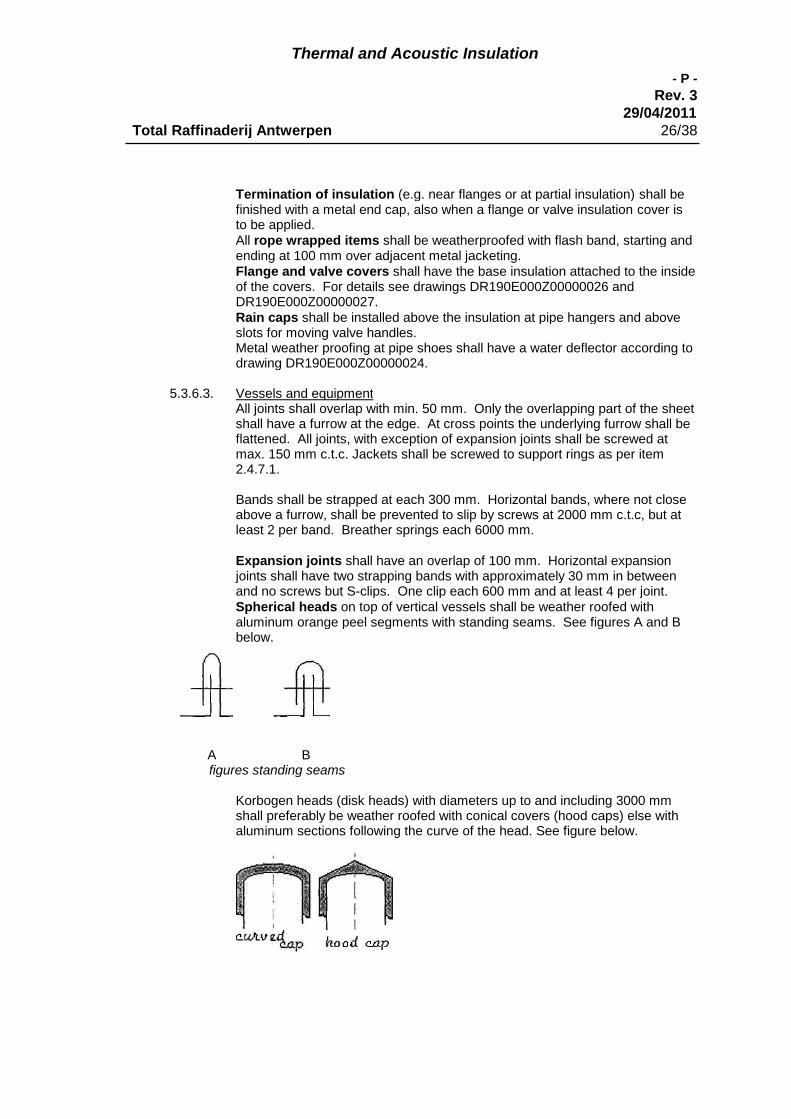
Thermal and Acoustic Insulation
- P -
Rev. 329/04/2011
Total Raffinaderij Antwerpen 26/38
Termination of insulation (e.g. near flanges or at partial insulation) shall befinished with a metal end cap, also when a flange or valve insulation cover isto be applied.All rope wrapped items shall be weatherproofed with flash band, starting andending at 100 mm over adjacent metal jacketing.Flange and valve covers shall have the base insulation attached to the insideof the covers. For details see drawings DR190E000Z00000026 andDR190E000Z00000027.Rain caps shall be installed above the insulation at pipe hangers and aboveslots for moving valve handles.Metal weather proofing at pipe shoes shall have a water deflector according todrawing DR190E000Z00000024.
5.3.6.3. Vessels and equipmentAll joints shall overlap with min. 50 mm. Only the overlapping part of the sheetshall have a furrow at the edge. At cross points the underlying furrow shall beflattened. All joints, with exception of expansion joints shall be screwed atmax. 150 mm c.t.c. Jackets shall be screwed to support rings as per item2.4.7.1.
Bands shall be strapped at each 300 mm. Horizontal bands, where not closeabove a furrow, shall be prevented to slip by screws at 2000 mm c.t.c, but atleast 2 per band. Breather springs each 6000 mm.
Expansion joints shall have an overlap of 100 mm. Horizontal expansionjoints shall have two strapping bands with approximately 30 mm in betweenand no screws but S-clips. One clip each 600 mm and at least 4 per joint.Spherical heads on top of vertical vessels shall be weather roofed withaluminum orange peel segments with standing seams. See figures A and Bbelow.
A Bfigures standing seams
Korbogen heads (disk heads) with diameters up to and including 3000 mmshall preferably be weather roofed with conical covers (hood caps) else withaluminum sections following the curve of the head. See figure below.

Thermal and Acoustic Insulation
- P -
Rev. 329/04/2011
Total Raffinaderij Antwerpen 27/38
Termination of insulation (e.g. near flanges or at partial insulation) shall befinished with a metal end cap, also when a flange cover or other type insulationcover is to be applied. A 3 mm hole shall be drilled at each lowest point fordrainage and leak detection.Pumps, turbines, compressors, etc., only when specifically indicated forinsulation, shall be insulated with a removable box without bottom resting onthe base plate. The insulation shall be attached to the inside of the box.Openings for in- and outgoing lines and leads shall be closed with screwedshields and sealant.
5.3.7. Storage tanks
5.3.7.1. The applicator shall prepare his design and procedures in accordance with thisspecification and in view of the insulation supports provided on the storagetank. See drawings DR190E000Z00000036.Bottom 300 mm of tank shell shall be kept free of insulation and lowest courseof insulation shall be made of water repellant insulation (multi-cellularglass/foam glass).
Installation of insulation plates shall be done according a stretcher bondarrangement.When a multiple layer arrangement is required, the joints shall be staggered.
Installation of insulation blankets on the tank shell, make ISOVER type PSI A1,shall be done by pressing these blankets over weld-bolts.
The M8 weld-bolts shall be installed every 600 mm horizontally and every 1500to 2000 mm vertically. The lowest weld-bolt row shall be located 320 mm fromthe tank bottom. Neoprene cladded nuts, fastened to the M8 weld-bolts, shallbe covered by special aluminum profiles (thickness = 3 mm). These aluminumjacket shall be fixed with 18/8 screws on those ALU-profiles.
5.3.7.2. Aluminum jacketThe aluminum jacket shall be aluminum corrugated plates minimum thickness0.8 mm. The plate length will relate to the tank diameter. Plate lengths ofminimum 4 m shall be used. The corrugated plates shall be fastenedhorizontally every 150 mm. The overlap between plates shall be minimum onecomplete corrugation. The corrugated plates shall be fastened vertically every250 mm.Corrugated plates shall be fixed to each other with self tapping screws withEPDM washer.
5.3.7.3. Alternative systems, such as prefab storage tank insulation systems or freehanging systems, may be submitted for approval to owner, together with fullinformation and data about technical and economical benefits.
5.4. Cold Insulation
General.
- The temperature limits of the adhesives and accessory products should be respectedduring both storage and application. Avoid applying foamglas insulation on pipes andequipment in service.
- Metal wire to fix foamglas should be avoided due to the wire cutting of the foamglassurface. Two stainless steel straps per standard length should be used. In case of
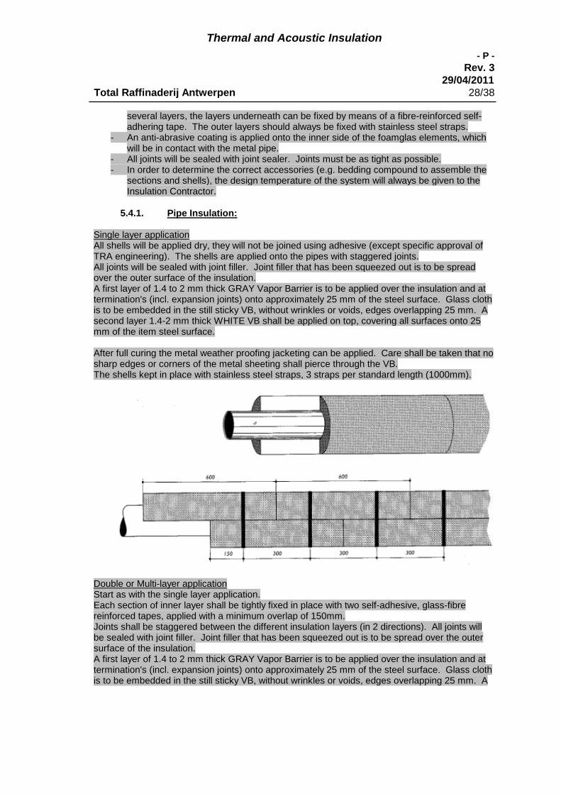
Thermal and Acoustic Insulation
- P -
Rev. 329/04/2011
Total Raffinaderij Antwerpen 28/38
several layers, the layers underneath can be fixed by means of a fibre-reinforced self-adhering tape. The outer layers should always be fixed with stainless steel straps.
- An anti-abrasive coating is applied onto the inner side of the foamglas elements, whichwill be in contact with the metal pipe.
- All joints will be sealed with joint sealer. Joints must be as tight as possible.- In order to determine the correct accessories (e.g. bedding compound to assemble the
sections and shells), the design temperature of the system will always be given to theInsulation Contractor.
5.4.1. Pipe Insulation:
Single layer applicationAll shells will be applied dry, they will not be joined using adhesive (except specific approval ofTRA engineering). The shells are applied onto the pipes with staggered joints.All joints will be sealed with joint filler. Joint filler that has been squeezed out is to be spreadover the outer surface of the insulation.A first layer of 1.4 to 2 mm thick GRAY Vapor Barrier is to be applied over the insulation and attermination's (incl. expansion joints) onto approximately 25 mm of the steel surface. Glass clothis to be embedded in the still sticky VB, without wrinkles or voids, edges overlapping 25 mm. Asecond layer 1.4-2 mm thick WHITE VB shall be applied on top, covering all surfaces onto 25mm of the item steel surface.
After full curing the metal weather proofing jacketing can be applied. Care shall be taken that nosharp edges or corners of the metal sheeting shall pierce through the VB.The shells kept in place with stainless steel straps, 3 straps per standard length (1000mm).
Double or Multi-layer applicationStart as with the single layer application.Each section of inner layer shall be tightly fixed in place with two self-adhesive, glass-fibrereinforced tapes, applied with a minimum overlap of 150mm.Joints shall be staggered between the different insulation layers (in 2 directions). All joints willbe sealed with joint filler. Joint filler that has been squeezed out is to be spread over the outersurface of the insulation.A first layer of 1.4 to 2 mm thick GRAY Vapor Barrier is to be applied over the insulation and attermination's (incl. expansion joints) onto approximately 25 mm of the steel surface. Glass clothis to be embedded in the still sticky VB, without wrinkles or voids, edges overlapping 25 mm. A
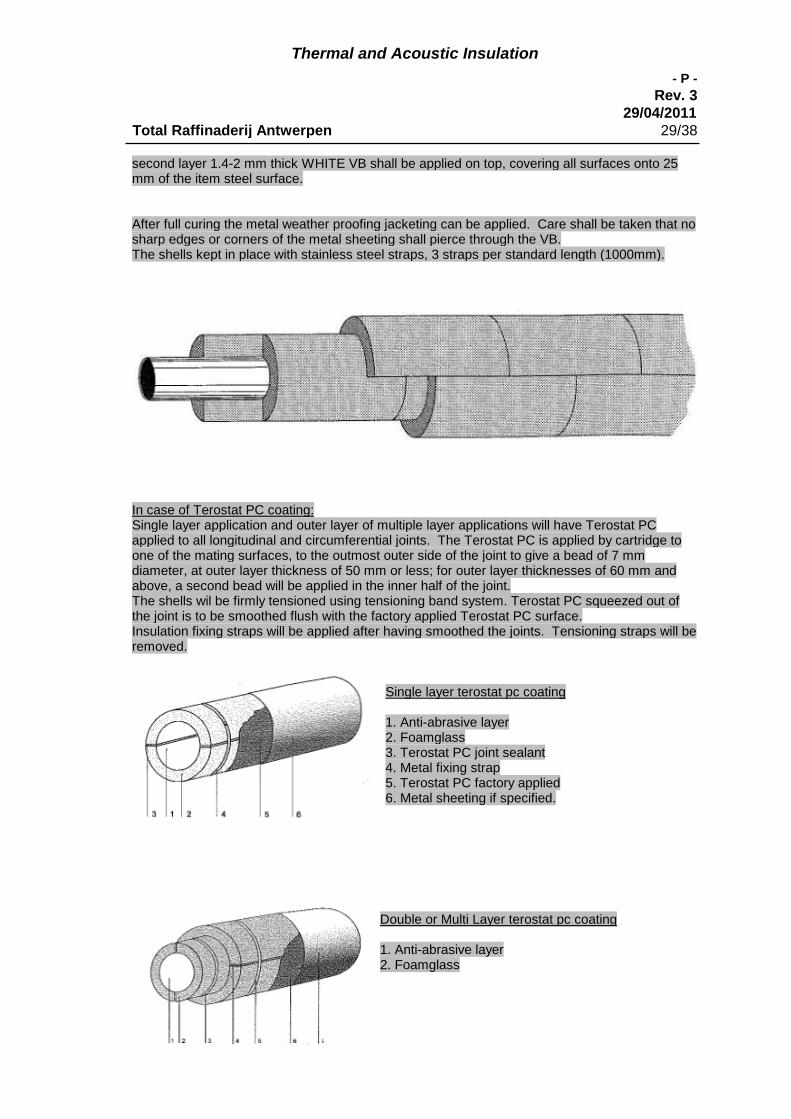
Thermal and Acoustic Insulation
- P -
Rev. 329/04/2011
Total Raffinaderij Antwerpen 29/38
second layer 1.4-2 mm thick WHITE VB shall be applied on top, covering all surfaces onto 25mm of the item steel surface.
After full curing the metal weather proofing jacketing can be applied. Care shall be taken that nosharp edges or corners of the metal sheeting shall pierce through the VB.The shells kept in place with stainless steel straps, 3 straps per standard length (1000mm).
In case of Terostat PC coating:Single layer application and outer layer of multiple layer applications will have Terostat PCapplied to all longitudinal and circumferential joints. The Terostat PC is applied by cartridge toone of the mating surfaces, to the outmost outer side of the joint to give a bead of 7 mmdiameter, at outer layer thickness of 50 mm or less; for outer layer thicknesses of 60 mm andabove, a second bead will be applied in the inner half of the joint.The shells wil be firmly tensioned using tensioning band system. Terostat PC squeezed out ofthe joint is to be smoothed flush with the factory applied Terostat PC surface.Insulation fixing straps will be applied after having smoothed the joints. Tensioning straps will beremoved.
Single layer terostat pc coating
1. Anti-abrasive layer2. Foamglass3. Terostat PC joint sealant4. Metal fixing strap5. Terostat PC factory applied6. Metal sheeting if specified.
Double or Multi Layer terostat pc coating
1. Anti-abrasive layer2. Foamglass
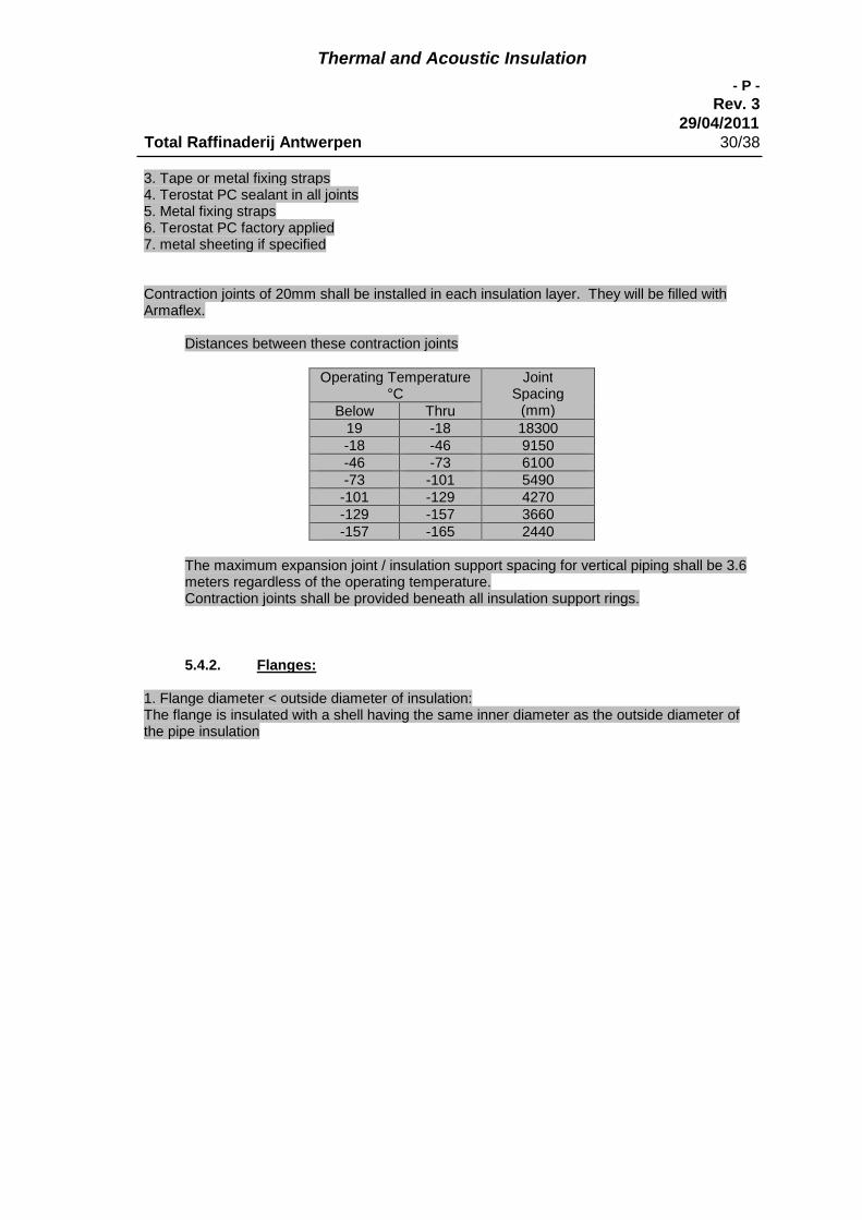
Thermal and Acoustic Insulation
- P -
Rev. 329/04/2011
Total Raffinaderij Antwerpen 30/38
3. Tape or metal fixing straps4. Terostat PC sealant in all joints5. Metal fixing straps6. Terostat PC factory applied7. metal sheeting if specified
Contraction joints of 20mm shall be installed in each insulation layer. They will be filled withArmaflex.
Distances between these contraction joints
Operating Temperature°C
JointSpacing
(mm)Below Thru19 -18 18300-18 -46 9150-46 -73 6100-73 -101 5490-101 -129 4270-129 -157 3660-157 -165 2440
The maximum expansion joint / insulation support spacing for vertical piping shall be 3.6meters regardless of the operating temperature.Contraction joints shall be provided beneath all insulation support rings.
5.4.2. Flanges:
1. Flange diameter < outside diameter of insulation:The flange is insulated with a shell having the same inner diameter as the outside diameter ofthe pipe insulation
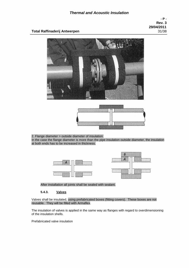
Thermal and Acoustic Insulation
- P -
Rev. 329/04/2011
Total Raffinaderij Antwerpen 31/38
2. Flange diameter > outside diameter of insulation:In the case the flange diameter is more than the pipe insulation outside diameter, the insulationat both ends has to be increased in thickness.
After installation all joints shall be sealed with sealant.
5.4.3. Valves
Valves shall be insulated, using prefabricated boxes (fitting covers). These boxes are notreusable. They will be filled with Armaflex.
The insulation of valves is applied in the same way as flanges with regard to overdimensioningof the insulation shells.
Prefabricated valve insulation
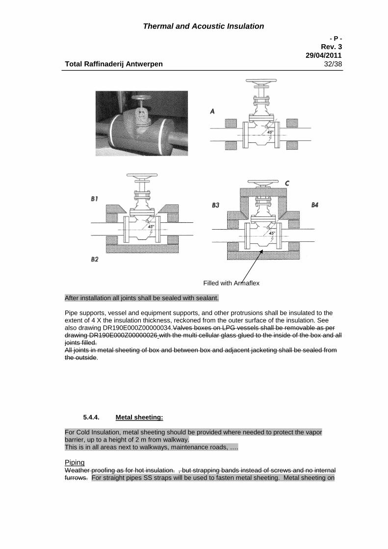
Thermal and Acoustic Insulation
- P -
Rev. 329/04/2011
Total Raffinaderij Antwerpen 32/38
Filled with Armaflex
After installation all joints shall be sealed with sealant.
Pipe supports, vessel and equipment supports, and other protrusions shall be insulated to theextent of 4 X the insulation thickness, reckoned from the outer surface of the insulation. Seealso drawing DR190E000Z00000034.Valves boxes on LPG vessels shall be removable as perdrawing DR190E000Z00000026 with the multi cellular glass glued to the inside of the box and alljoints filled.All joints in metal sheeting of box and between box and adjacent jacketing shall be sealed fromthe outside.
5.4.4. Metal sheeting:
For Cold Insulation, metal sheeting should be provided where needed to protect the vaporbarrier, up to a height of 2 m from walkway.This is in all areas next to walkways, maintenance roads, ….
PipingWeather proofing as for hot insulation. , but strapping bands instead of screws and no internalfurrows. For straight pipes SS straps will be used to fasten metal sheeting. Metal sheeting on
Thermal and Acoustic Insulation
- P -
Rev. 329/04/2011
Total Raffinaderij Antwerpen 33/38
bends will be fastened with popnails. In this case an extra layer (10mm) of bubble wrap will beapplied underneath the metal sheeting.Valves and flanges shall have the insulation fitted and glued to the inside of the box. And the VBshall be applied over the cold side of the insulation.After installation all joints shall be sealed with sealant.
Vessels and equipmentWeather proofing as for hot insulation, but without screws. Popnails can be used, if an extralayer (10mm) of bubble wrap is applied underneath the metal sheetingHorizontal joints on vertical items shall be provided with S-clips.Slippage of horizontal strapping bands shall be prevented by clips riveted to the metal sheetingbefore application. One clip each 2 m and at least 2 clips per joint. Hand Inspection holes andmanholes and flange covers to be insulated and sealed as outlined for piping/valves/flanges.
6. Acoustic insulation
6.1. General
6.1.1. Acoustic insulation is only effective when there is no metal to metal contactbetween insulated surface and metal jacketing.Supports and attachment points shall be acoustically separated by antivibration seals. Contact points shall be avoided.
6.1.2. Application is generally same as for hot insulation.
6.1.3. Combined hot and acoustic insulation shall be according the most severerequirements of each class.
6.1.4. Combined cold and acoustic insulation shall have the acoustic base insulationon top of the cold base insulation., the vapour barrier and metal jacketing shallbe applied over the acoustic insulation.Each case of acoustic/cold insulation will be reviewed separately to find thebest solution for that specific case.If the total thickness meets construction restraints, then locally the thickness ofeach layer shall be equally reduced in agreement with owner.
6.2. Category A
Base insulation 50 mm preformed pipe sections or board. Aluminum weather proofjacketing, minimum thickness 0.8 mm.Flange and valves, hand and manholes, etc., shall not be insulated.
6.3. Category B
Base insulation 100 mm preformed pipe sections or board.Aluminized steel weather proof jacketing, minimum thickness 0.8 mm.Flange and valves, hand and manholes, etc., shall be insulated.
6.4. Category C
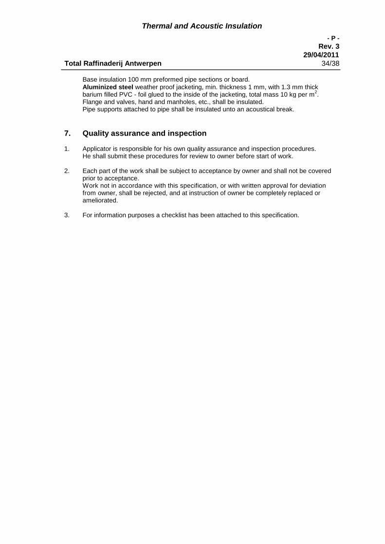
Thermal and Acoustic Insulation
- P -
Rev. 329/04/2011
Total Raffinaderij Antwerpen 34/38
Base insulation 100 mm preformed pipe sections or board.Aluminized steel weather proof jacketing, min. thickness 1 mm, with 1.3 mm thickbarium filled PVC - foil glued to the inside of the jacketing, total mass 10 kg per m
2.
Flange and valves, hand and manholes, etc., shall be insulated.Pipe supports attached to pipe shall be insulated unto an acoustical break.
7. Quality assurance and inspection
1. Applicator is responsible for his own quality assurance and inspection procedures.He shall submit these procedures for review to owner before start of work.
2. Each part of the work shall be subject to acceptance by owner and shall not be coveredprior to acceptance.Work not in accordance with this specification, or with written approval for deviationfrom owner, shall be rejected, and at instruction of owner be completely replaced orameliorated.
3. For information purposes a checklist has been attached to this specification.
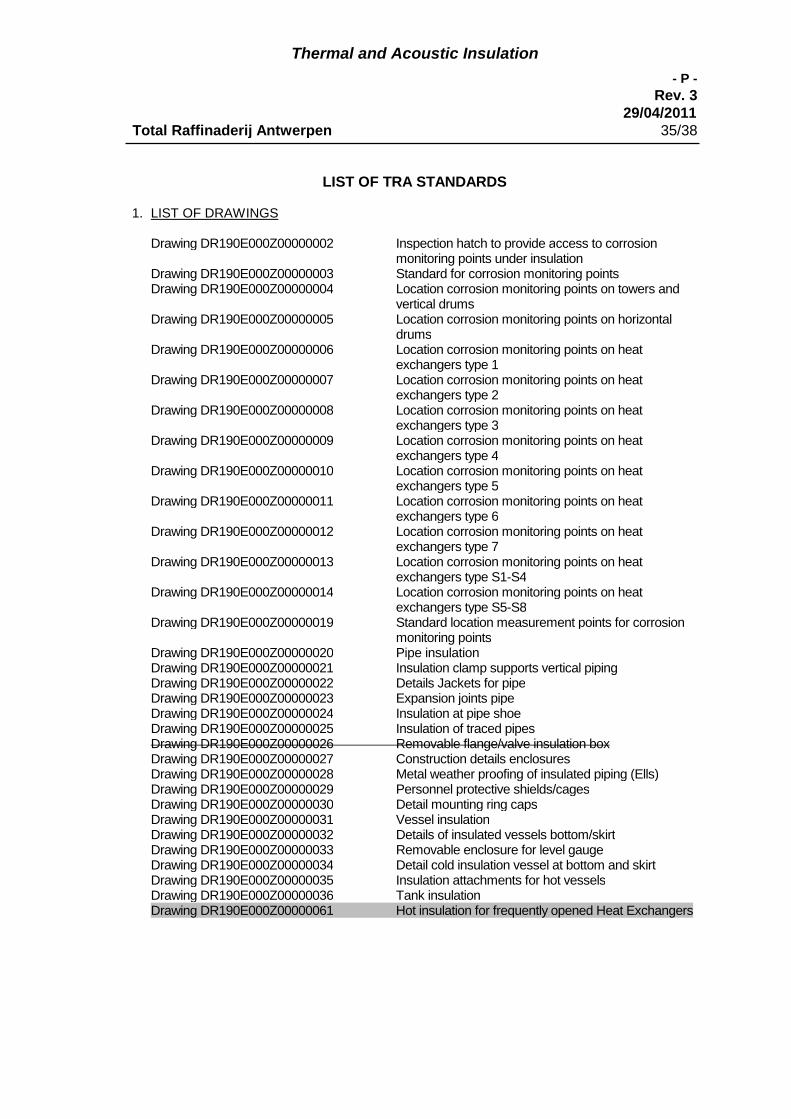
Thermal and Acoustic Insulation
- P -
Rev. 329/04/2011
Total Raffinaderij Antwerpen 35/38
LIST OF TRA STANDARDS
1. LIST OF DRAWINGS
Drawing DR190E000Z00000002 Inspection hatch to provide access to corrosionmonitoring points under insulation
Drawing DR190E000Z00000003 Standard for corrosion monitoring pointsDrawing DR190E000Z00000004 Location corrosion monitoring points on towers and
vertical drumsDrawing DR190E000Z00000005 Location corrosion monitoring points on horizontal
drumsDrawing DR190E000Z00000006 Location corrosion monitoring points on heat
exchangers type 1Drawing DR190E000Z00000007 Location corrosion monitoring points on heat
exchangers type 2Drawing DR190E000Z00000008 Location corrosion monitoring points on heat
exchangers type 3Drawing DR190E000Z00000009 Location corrosion monitoring points on heat
exchangers type 4Drawing DR190E000Z00000010 Location corrosion monitoring points on heat
exchangers type 5Drawing DR190E000Z00000011 Location corrosion monitoring points on heat
exchangers type 6Drawing DR190E000Z00000012 Location corrosion monitoring points on heat
exchangers type 7Drawing DR190E000Z00000013 Location corrosion monitoring points on heat
exchangers type S1-S4Drawing DR190E000Z00000014 Location corrosion monitoring points on heat
exchangers type S5-S8Drawing DR190E000Z00000019 Standard location measurement points for corrosion
monitoring pointsDrawing DR190E000Z00000020 Pipe insulationDrawing DR190E000Z00000021 Insulation clamp supports vertical pipingDrawing DR190E000Z00000022 Details Jackets for pipeDrawing DR190E000Z00000023 Expansion joints pipeDrawing DR190E000Z00000024 Insulation at pipe shoeDrawing DR190E000Z00000025 Insulation of traced pipesDrawing DR190E000Z00000026 Removable flange/valve insulation boxDrawing DR190E000Z00000027 Construction details enclosuresDrawing DR190E000Z00000028 Metal weather proofing of insulated piping (Ells)Drawing DR190E000Z00000029 Personnel protective shields/cagesDrawing DR190E000Z00000030 Detail mounting ring capsDrawing DR190E000Z00000031 Vessel insulationDrawing DR190E000Z00000032 Details of insulated vessels bottom/skirtDrawing DR190E000Z00000033 Removable enclosure for level gaugeDrawing DR190E000Z00000034 Detail cold insulation vessel at bottom and skirtDrawing DR190E000Z00000035 Insulation attachments for hot vesselsDrawing DR190E000Z00000036 Tank insulationDrawing DR190E000Z00000061 Hot insulation for frequently opened Heat Exchangers

Thermal and Acoustic Insulation
- P -
Rev. 329/04/2011
Total Raffinaderij Antwerpen 36/38
2. INSULATION CHECKLIST
2.1. Purpose
This checklist belongs to TRA. Insulation specification "P" and is for the sole purpose ofquality control by owner.
2.2. Limitations
This checklist does not cover overall inspection items, such as good workmanship,cosmetic appearance, calculations, etc.It shall in no way be used instead of said specification or replace the quality proceduresof the applicator
2.2.1. Instructions
Read the specification and consult it constantly.
General contains items relevant to all parts and procedures of the work and is to be read inconjunction with the applicable additional sheets stated hereunder.
2.3.2. Piping2.3.3. Vessels and equipment2.3.4. Acoustic2.3.5. Cold
2.3.1. GeneralBefore application Safety and health procedures observed Weather conditions favourable Coating integer Surface clean Stainless steel wrapped with alu foil no exposed parts Welded supports provided Correct material handling and storage Required documentation (e.g. contracts, specification, SA, certificates) available at
site
Base material Correct type and thickness Fibrous insulation kept dry at all procedures Applied with staggered joints where required No open joints, close snugly fitting No galvanised wire/bands or accessories near stainless steel items Cuttings, scrap material and waste removed same day
Weather proofing Immediately after application base insulation, else temporary plastic protection Correct material (steel sheet for acoustic C & D, and fire proofing insulation) No sharp edges, bent corners, dents Correct furrowing
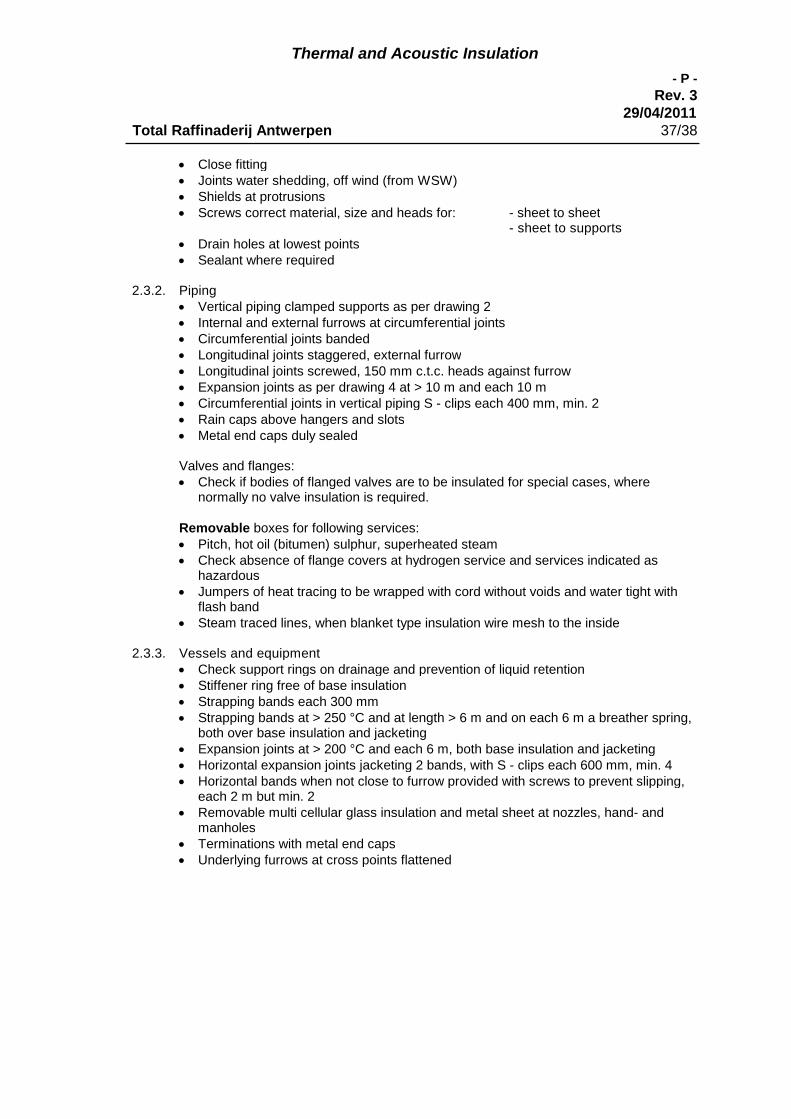
Thermal and Acoustic Insulation
- P -
Rev. 329/04/2011
Total Raffinaderij Antwerpen 37/38
Close fitting Joints water shedding, off wind (from WSW) Shields at protrusions Screws correct material, size and heads for: - sheet to sheet
- sheet to supports Drain holes at lowest points Sealant where required
2.3.2. Piping Vertical piping clamped supports as per drawing 2 Internal and external furrows at circumferential joints Circumferential joints banded Longitudinal joints staggered, external furrow Longitudinal joints screwed, 150 mm c.t.c. heads against furrow Expansion joints as per drawing 4 at > 10 m and each 10 m Circumferential joints in vertical piping S - clips each 400 mm, min. 2 Rain caps above hangers and slots Metal end caps duly sealed
Valves and flanges: Check if bodies of flanged valves are to be insulated for special cases, where
normally no valve insulation is required.
Removable boxes for following services: Pitch, hot oil (bitumen) sulphur, superheated steam Check absence of flange covers at hydrogen service and services indicated as
hazardous Jumpers of heat tracing to be wrapped with cord without voids and water tight with
flash band Steam traced lines, when blanket type insulation wire mesh to the inside
2.3.3. Vessels and equipment Check support rings on drainage and prevention of liquid retention Stiffener ring free of base insulation Strapping bands each 300 mm Strapping bands at > 250 °C and at length > 6 m and on each 6 m a breather spring,
both over base insulation and jacketing Expansion joints at > 200 °C and each 6 m, both base insulation and jacketing Horizontal expansion joints jacketing 2 bands, with S - clips each 600 mm, min. 4 Horizontal bands when not close to furrow provided with screws to prevent slipping,
each 2 m but min. 2 Removable multi cellular glass insulation and metal sheet at nozzles, hand- and
manholes Terminations with metal end caps Underlying furrows at cross points flattened

Thermal and Acoustic Insulation
- P -
Rev. 329/04/2011
Total Raffinaderij Antwerpen 38/38
2.3.4. Acoustic Check carefully on absence of metal to metal contact between jacketing- and the
insulated item Check carefully on noise leaks through open joints, etc. Category B to be provided with steel jacketing 0.8 mm thick Category C to be provided with steel jacketing 1 mm thick with the heavy filled foil
glued to the inside
2.3.5. Cold Bedding compound equally distributed over the surface Sections / block perfectly aligned Joints completely filled Squeezed out filler spread out Expansion joints < minus 10 °c and each 6 m stuffed with wool Gray VB completely covering multi cellular glass and expansion joints -1.4 to 2 mm
thick onto 5 mm of steel surface of insulated item Glass cloth smooth applied without wrinkles, overlap 5 mm at edges onto 5 mm of
item White VB completely hiding glass cloth and gray VB -1.4 to 2 mm thick Check curing; after fully cured Jacketing no internal furrows
- to be provided where required, before application, with riveted clips toprevent slippage of horizontal bands
- to be checked on sharp edges, corners, and anything that can endangerthe integrity of the VB
All joints sealed.

INSPECTION HATCH TO PROVIDE ACCESS TO CORROSION MONITORING POINTS UNDER INSULATION - DR179E000Z00000001 (Revision 0)- (Revision 0) (1/1)
Printed on: 08/08/2012 at 16:44, GUEST GUEST Database : GEDEON
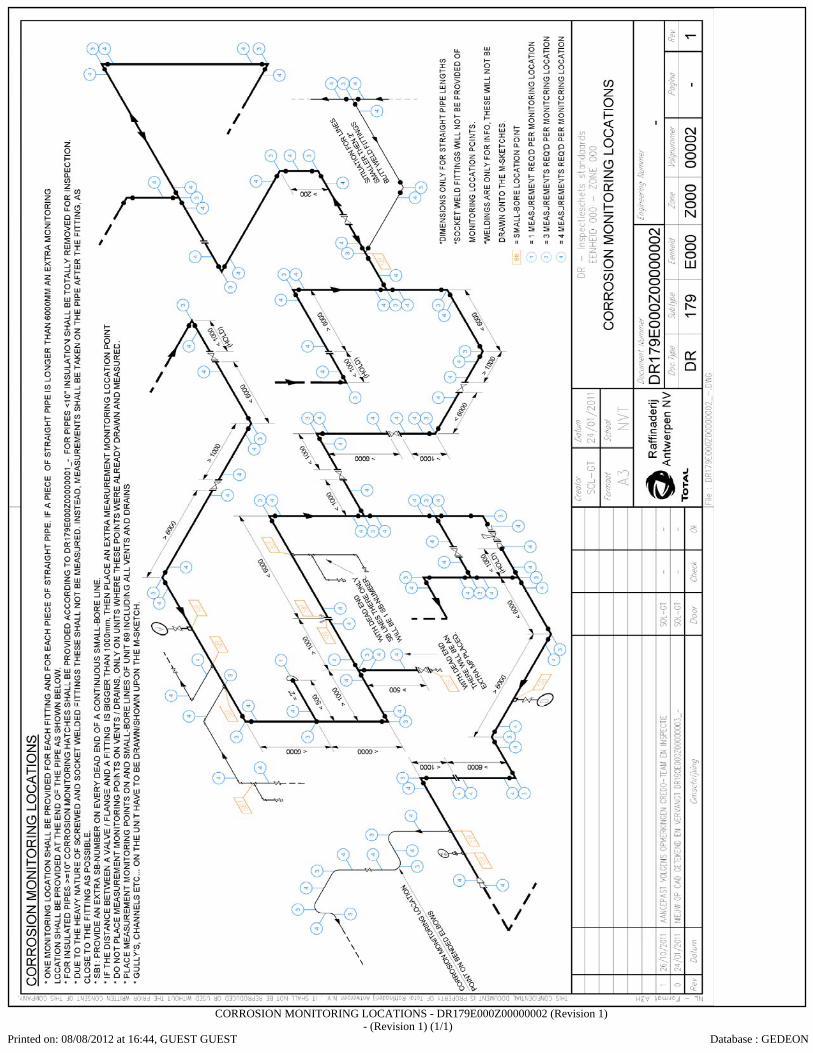
CORROSION MONITORING LOCATIONS - DR179E000Z00000002 (Revision 1)- (Revision 1) (1/1)
Printed on: 08/08/2012 at 16:44, GUEST GUEST Database : GEDEON