oprf parking structure maintenance repairs · oprf parking structure maintenance repairs ... the...
TRANSCRIPT

SPECIFICATIONS FOR
OPRF PARKING
STRUCTURE
MAINTENANCE REPAIRS OAK PARK, ILLINOIS
Prepared For:
VILLAGE OF OAK PARK
DATE ISSUED
JULY 26, 2017
WALKER PROJECT NO. 31-8130.10
ORRF PARKING STRUCTURE Construction Documents Maintenance Repairs July, 2017 Project Number 31-8130.10
© Copyright 2017, Walker Restoration Consultants. All rights reserved. TABLE OF CONTENTS 000110 - 1
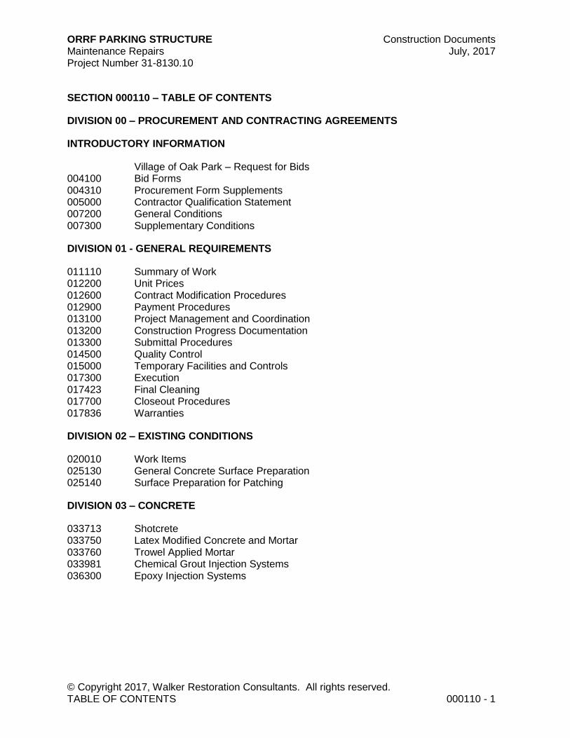
SECTION 000110 – TABLE OF CONTENTS
DIVISION 00 – PROCUREMENT AND CONTRACTING AGREEMENTS
INTRODUCTORY INFORMATION
Village of Oak Park – Request for Bids 004100 Bid Forms 004310 Procurement Form Supplements 005000 Contractor Qualification Statement 007200 General Conditions 007300 Supplementary Conditions
DIVISION 01 - GENERAL REQUIREMENTS
011110 Summary of Work 012200 Unit Prices 012600 Contract Modification Procedures 012900 Payment Procedures 013100 Project Management and Coordination 013200 Construction Progress Documentation 013300 Submittal Procedures 014500 Quality Control 015000 Temporary Facilities and Controls 017300 Execution 017423 Final Cleaning 017700 Closeout Procedures 017836 Warranties
DIVISION 02 – EXISTING CONDITIONS
020010 Work Items 025130 General Concrete Surface Preparation 025140 Surface Preparation for Patching
DIVISION 03 – CONCRETE
033713 Shotcrete 033750 Latex Modified Concrete and Mortar 033760 Trowel Applied Mortar 033981 Chemical Grout Injection Systems 036300 Epoxy Injection Systems
ORRF PARKING STRUCTURE Construction Documents Maintenance Repairs July, 2017 Project Number 31-8130.10
© Copyright 2017, Walker Restoration Consultants. All rights reserved. TABLE OF CONTENTS 000110 - 2
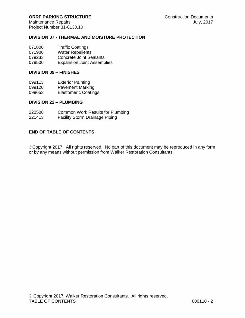
DIVISION 07 - THERMAL AND MOISTURE PROTECTION
071800 Traffic Coatings 071900 Water Repellents 079233 Concrete Joint Sealants 079500 Expansion Joint Assemblies
DIVISION 09 – FINISHES
099113 Exterior Painting 099120 Pavement Marking 099653 Elastomeric Coatings
DIVISION 22 – PLUMBING
220500 Common Work Results for Plumbing 221413 Facility Storm Drainage Piping
END OF TABLE OF CONTENTS
Copyright 2017. All rights reserved. No part of this document may be reproduced in any form or by any means without permission from Walker Restoration Consultants.

Request for Bids
For the repair of the OPRF Garage within the Village of Oak Park
Village of Oak Park
Proposal No.: WALKER PROJECT NO.31-8130.10
Date Issued: July 26, 2017
Proposal Deadline:
Tuesday, August 15, 2017 at 2:00 p.m. local time
Sealed Bids to be returned to: John Youkhana, Parking and Mobility Services
Oak Park Village Hall 123 Madison Street Oak Park, IL 60302
Monday – Friday
8:30 am to 5:00 pm
Proposal Bond: 10% of Bid
Page 2 of 12 Village of Oak Park
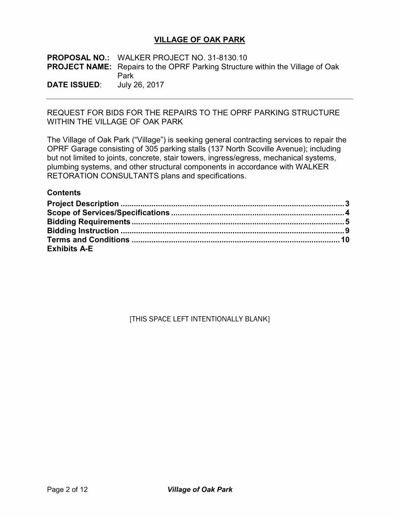
VILLAGE OF OAK PARK PROPOSAL NO.: WALKER PROJECT NO. 31-8130.10 PROJECT NAME: Repairs to the OPRF Parking Structure within the Village of Oak
Park DATE ISSUED: July 26, 2017
REQUEST FOR BIDS FOR THE REPAIRS TO THE OPRF PARKING STRUCTURE WITHIN THE VILLAGE OF OAK PARK The Village of Oak Park (“Village”) is seeking general contracting services to repair the OPRF Garage consisting of 305 parking stalls (137 North Scoville Avenue); including but not limited to joints, concrete, stair towers, ingress/egress, mechanical systems, plumbing systems, and other structural components in accordance with WALKER RETORATION CONSULTANTS plans and specifications.
Contents
Project Description ...................................................................................................... 3 Scope of Services/Specifications ............................................................................... 4 Bidding Requirements ................................................................................................. 5 Bidding Instruction ...................................................................................................... 9 Terms and Conditions ............................................................................................... 10 Exhibits A-E
[THIS SPACE LEFT INTENTIONALLY BLANK]

Page 3 of 12 Village of Oak Park
Project Description
Location
The OPRF Parking Garage will be located at 127 North Scoville Avenue, Oak Park, Illinois. Parking Facilities Description
The OPRF Parking Garage is a 300 parking stall facility with one access point. This access point includes one entrance lane, one exit lane. There is one pay-on-foot stations, programmed to work as pay by space. There is no management and no security offices located in the garage. .
[THIS SPACE LEFT INTENTIONALLY BLANK]
Page 4 of 12 Village of Oak Park
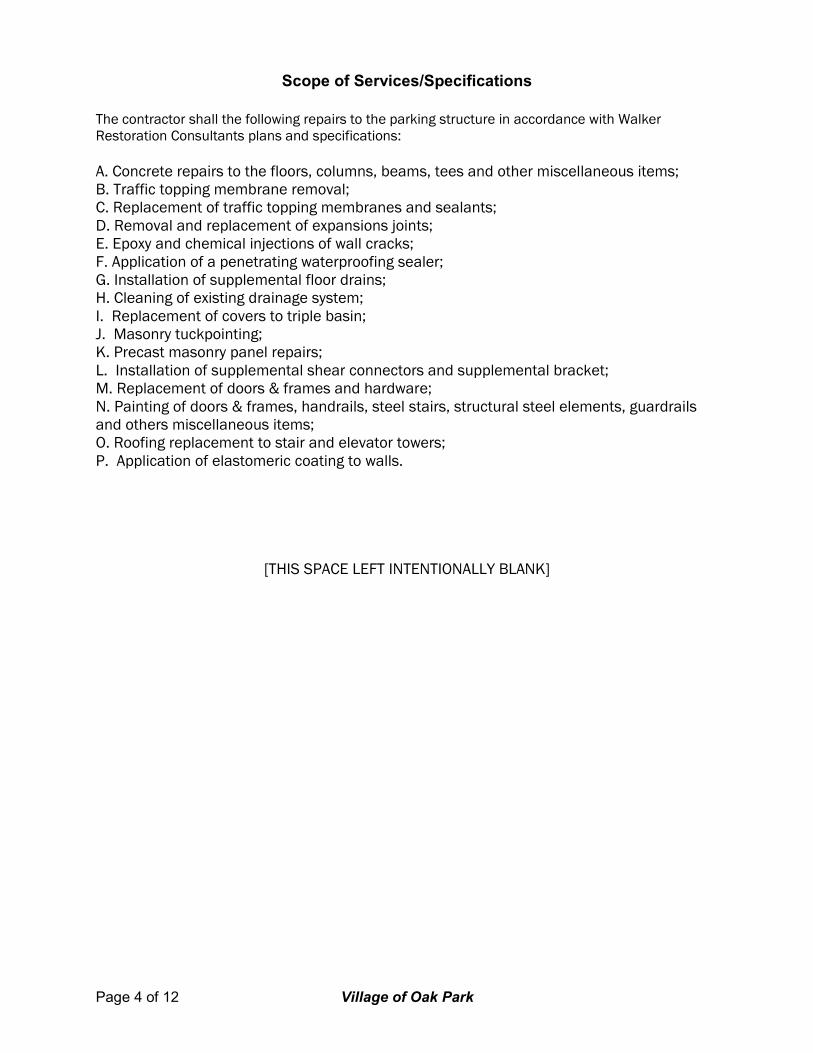
Scope of Services/Specifications
The contractor shall the following repairs to the parking structure in accordance with Walker Restoration Consultants plans and specifications:
A. Concrete repairs to the floors, columns, beams, tees and other miscellaneous items; B. Traffic topping membrane removal; C. Replacement of traffic topping membranes and sealants; D. Removal and replacement of expansions joints; E. Epoxy and chemical injections of wall cracks; F. Application of a penetrating waterproofing sealer; G. Installation of supplemental floor drains; H. Cleaning of existing drainage system; I. Replacement of covers to triple basin; J. Masonry tuckpointing; K. Precast masonry panel repairs; L. Installation of supplemental shear connectors and supplemental bracket; M. Replacement of doors & frames and hardware; N. Painting of doors & frames, handrails, steel stairs, structural steel elements, guardrails and others miscellaneous items; O. Roofing replacement to stair and elevator towers; P. Application of elastomeric coating to walls.
[THIS SPACE LEFT INTENTIONALLY BLANK]
Page 5 of 12 Village of Oak Park
Bidding Requirements Bids shall include the following: 1. List of Unit Prices Project cost will be based upon total cost of the unit prices multiplied by the estimated quantity of the anticipated repairs. Please fill out Section 004310 and attach it to your bidding documents. 2. Contractor’s Qualification Statement Contractor’s Qualification Statement, Section 00500, must be submitted with your bidding documents. 3. Prevailing Wages Pursuant to the requirements of the State of Illinois Department of Labor, there have been established minimum scales of hourly wages to be paid in each classification of labor under this contract. The contractor and each subcontractor shall pay wages equal to or greater than the established minimum scales or hourly wages as determined by the State of Illinois Department of Labor. The wage rate set forth shall in no way be construed to prevent the contractor or subcontractors from paying a higher rate of wages. If any crafts establish a higher minimum wage in the district during the construction, the higher minimum wage established shall be considered as having also been established as the minimum wage scale under this contract. The contractor shall incorporate all applicable minimum wage rates published prior to the date of the bid opening into the contract documents. It shall be the responsibility of the successful contractor to monitor the prevailing wage rates as established with the Department of Labor for any increase in rates during the project and adjust wage rates accordingly. Prevailing wages rates are available via the internet at www.state.il.us/agency/idol. Contractors/subcontractors are responsible for checking on all rate revisions to the prevailing wage rate act for the contract duration. Pursuant to 820 ILCS 130/5, contractors are to submit signed certified payroll to the Village no later than the tenth day of each calendar month for the immediately preceding month during those months when construction on a public works project has occurred for each project awarded. The certified payroll must list all laborer, mechanics, and other workers employed on the project, each worker’s address, telephone number (when available), social security number, classification, hourly wages paid in each pay period, number of hours worked each day, and the starting and ending times of work each day. The certified payroll must be accompanied by a statement signed by the owner/contractor or subcontractor or an officer, employee or agent of the contractor or subcontractor which avers that he or she has examined the certified payroll records required to be submitted by the Act and such records are true and accurate ; the hourly rate paid to each worker is not less than the general prevailing rate of hourly wages required by this Act ; and the contractor or subcontractor is aware that filing a certified payroll that he or she knows to be false is a Class A misdemeanor. Identify all key personnel directly involved in this Project and provide information on their backgrounds including education, experience, and professional designations. Include any other relevant credentials. 4. Insurance Requirements The Contractor shall not commence work until the Contractor has obtained all insurance required in these documents. The Contractor shall purchase and maintain, throughout the duration of the contract, insurance as is appropriate for the work being performed and furnished and shall provide protection from claims which may arise out of or result from the Contractor’s performance and furnishing of the work and Contractor’s other obligations under the contract documents, whether

Page 6 of 12 Village of Oak Park
it is to be performed or furnished by the Contractor, by any Subcontractor, by anyone directly or indirectly employed by them or by anyone for whose acts any of them may be liable.
(b) Insurance required by this Section shall be written with a company having at least an “A” Property-Casualty Rating, and financial size of at least Class 7 as listed in the most recent published A. M. Best’s Insurance Guide. (c) The Village shall be named as additional insured except for Workmen’s Compensation insurance. The coverage afforded shall be primary and non-contributory for the additional insured with respect to claims arising out of operations preformed by or on behalf on the Contractor. If the additional insured has other insurance which is applicable to the loss, such as other insurance shall be on an excess or contingent basis. The amount of the Contractor’s insurance company’s liability under this insurance policy shall not be reduced by the existence of such other insurance. (d) As a minimum, the contractor shall secure and maintain the types of insurance as specified, and shall submit evidence to the Village on an annual basis that the insurance coverage’s are in force. The form and limits of such insurance, together with the underwriter thereof in each case, shall be acceptable to the Village, but regardless of such acceptance it shall be the responsibility of the Contractor to main adequate insurance coverage until final payment and at all times thereafter when the Contractor may be correcting, removing, or replacing defective work in accordance with the General Conditions and Instruction to Bidders. Failure of the Contractor to maintain adequate coverage shall not relieve him of any contractual responsibility or obligation. (e) The Contractor shall forward original copies of the Certificates of Insurance with the coverage’s and limits specified to the Purchasing Division, Finance Department, 9446 South Raymond Avenue, Oak Lawn, IL 60005. (f) Insurance Certificates and Policies delivered to the Village shall recite that 30 days prior written notice will be given to the Village by certified mail before any policy is materially changed, canceled, or not renewed.
WORKER’S COMPENSATION AND EMPLOYERS LIABILITY:
The insurance shall protect the Contractor against all claims under applicable State or Federal Worker’s Compensation Laws. The Contractor shall also be protected against claims for injury, disease or death of employees which for any reason may not fall within the provisions of the Worker’s Compensation Law. The policy shall include “broad form all states” endorsement coverage extended to cover all states except the monopolistic fund states.
The liability limits shall not be less than: 1. Worker’s Compensation .......................................................................... Statutory 2. Employer’s Liability ..................................................... $1,000,000 per occurrence
BUSINESS AUTO LIABILITY:
The insurance shall be written in automobile liability form and shall protect the Contractor against all claims for injuries to persons and damages to property arising from the ownership, maintenance or use of any motor vehicles and shall cover operation on or off the site of all motor vehicles, whether they are owned, non-owned or hired.
The liability limits shall not be less than: 1. Bodily Injury and Property Damage Combined ............ $1,000,000 per occurrence
Page 7 of 12 Village of Oak Park
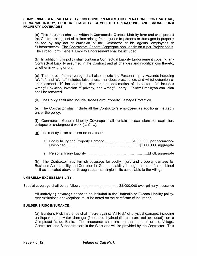
COMMERCIAL GENERAL LIABILITY, INCLUDING PREMISES AND OPERATIONS, CONTRACTUAL, PERSONAL INJURY, PRODUCT LIABILITY, COMPLETED OPERATIONS, AND BROAD FORM PROPERTY COVERAGES:
(a) This insurance shall be written in Commercial General Liability form and shall protect the Contractor against all claims arising from injuries to persons or damages to property caused by any act or omission of the Contractor or his agents, employees or Subcontractors. The Contractors General Aggregate shall apply on a per Project basis. The Broad Form General Liability Endorsement shall be included. (b) In addition, this policy shall contain a Contractual Liability Endorsement covering any Contractual Liability assumed in the Contract and all changes and modifications thereto, whether in writing or oral. (c) The scope of the coverage shall also include the Personal Injury Hazards including “a”, “b”, and “c”. “a” includes false arrest, malicious prosecution, and willful detention or imprisonment. “b” includes libel, slander, and defamation of character. “c” includes wrongful eviction, invasion of privacy, and wrongful entry. Fellow Employee exclusion shall be removed. (d) The Policy shall also include Broad Form Property Damage Protection. (e) The Contractor shall include all the Contractor’s employees as additional insured’s under the policy. (f) Commercial General Liability Coverage shall contain no exclusions for explosion, collapse or underground work (X, C, U). (g) The liability limits shall not be less than:
1. Bodily Injury and Property Damage .......................... $1,000,000 per occurrence Combined ........................................................................ $2,000,000 aggregate
2. Personal Injury Liability .............................................................BFGL aggregate (h) The Contractor may furnish coverage for bodily injury and property damage for Business Auto Liability and Commercial General Liability through the use of a combined limit as indicated above or through separate single limits acceptable to the Village.
UMBRELLA EXCESS LIABILITY:
Special coverage shall be as follows ...................................... $3,000,000 over primary insurance All underlying coverage needs to be included in the Umbrella or Excess Liability policy.
Any exclusions or exceptions must be noted on the certificate of insurance. BUILDER’S RISK INSURANCE:
(a) Builder’s Risk insurance shall insure against “All Risk” of physical damage, including earthquake and water damage (flood and hydrostatic pressure not excluded), on a Completed Value Basis. The insurance shall include the interests of the Village, Contractor, and Subcontractors in the Work and will be provided by the Contractor. This

Page 8 of 12 Village of Oak Park
policy shall be written or endorsed to allow the Village to occupy or use a portion or portions of the Work prior to completion of all the Work. (b) If not covered under the “All Risk” insurance or otherwise provided in the bid documents, the Contractor shall effect and maintain similar property insurance on portions of the Work stored on or off site or in transit, when such portions of the Work are to be included in an Application for Payment.
OWNERS PROTECTIVE LIABILITY INSURANCE:
Owners Protective Liability Policy shall be a stand-alone policy or an endorsement to the liability policy that covers claims for negligence by a contractor or a subcontractor hired by the insured. The policy limit shall be not less than $1,000,000 per occurrence and the named insured on the policy shall be the Village of Oak Park. All insurance programs will be required to be in conformance with Village’s standards as described later in this document and any applicable Contract with the selected Contractor. 5. Contract The Village will provide at a later time a copy of a proposed contract. Notwithstanding the foregoing sentence, the contract shall have a 30-day cancellation right for the Village. Indicate revisions requested in redline which the Village may accept or reject at its sole discretion. 6. Village of Oak Park Attachments per Exhibits A-E Please complete and attach copies of the following forms with your proposal.
Exhibit A - Proposal Form Exhibit B - Organization of Contracting Firm Exhibit C - Compliance Affidavit Exhibit D - M/W/DBE Status Exhibit E - EEO Report
[THIS SPACE LEFT INTENTIONALLY BLANK]
Page 9 of 12 Village of Oak Park
BIDDING INSTRUCTIONS
Bid Submittal Instructions
The village will receive Bids at the Oak Park Village Hall, Monday through Friday, 8:30 am to 2:00 pm, at 123 Madison Street, Oak Park, Illinois 60302. Bids should be submitted by 2:00 pm local time, August 15, 2017. Contracting firms should indicate the Walker’s Project Number and OPRF Parking Structure on the outside of their envelope. Contractors are to submit three (3) bound hard copies of the bid forms. Pre-Bid Meeting
A walk-through Pre-Bid Meeting will be held Wednesday, August 2, 2017 at 10:00 am local time at the project site. Questions regarding the work and other related documents may be submitted in writing to John Youkhana, Assistant Director, Village of Oak Park, Parking and Mobility Services, 123 Madison St., Oak Park, IL 60302, or by email to: [email protected], no later than Thursday, August 3, 2017 by 5:00 p.m. local time. A log of Contractor questions will be maintained and answers shared with all Contractors who have given their contact information to the Village via email.
Page 10 of 12 Village of Oak Park
Village of Oak Park Terms and Conditions
Preparation and Submission of Bid All bids must be delivered to the Oak Park Village Hall by the specific time indicated on the cover page. Bids arriving after the specified time will not be accepted. Mailed Bids that are received by the Village after the specified hour will not be accepted regardless of the post-marked time on the envelope. The Bid must be signed by an officer of the company who is authorized to enter into contracts on behalf of the company. Bids shall be sealed in an envelope and marked as stated on the cover page. Award of Contract The contract will be awarded in whole or in part to the responsible Contractor or Contractors whose Bids, conforming to the Request for Bids, will be most advantageous to the Village; price and other factors considered. Costs of Preparation The Village will not be responsible for any expenses incurred by the Contractor in preparing and submitting a Bid. Taxes not Applicable The Village of Oak Park as a municipality pays neither Illinois Sales Tax nor Federal Excise Tax (State Tax Exemption Identification Number E9998-1823-06). Contractors should exclude these taxes from their prices. Withdrawal of Bids Any Contractor may withdraw their proposal at any time prior to the time specified in the advertisement as the closing time for the receipt of Bids, by signing a request therefore. However, no Contractor shall withdraw or cancel their proposal for a period of thirty (30) calendar days after said advertised closing time for the receipt of Bids; the successful Contractor shall not withdraw or cancel their proposal after having been notified by the Director of Parking and Mobility Services or her designee that said proposal has been accepted by the Village Board of Trustees. The Village Board of Trustees reserves the right to accept or reject any and all Bids or to waive technicalities, or to accept any item of any proposal unless the Contractor includes a restrictive limitation. Competency of Contractor No proposal will be accepted from or contract awarded to any person, firm or corporation that appears to be in default, or in any debt of any contract. The Contractor, if requested, must present evidence to the Parking and Mobility Services Director of ability and possession of necessary staff, facilities, equipment and financial resources to comply with the terms of the attached specifications and Bids. Rejection of Contractor The Village will reject any Proposal from any person, firm or corporation that appears to be in default or arrears on any debt, contract or the payment of any taxes. The Village will reject any Proposal from a Contractor that failed to satisfactorily complete work for the Village under any previous contract. Conditions Contractors are advised to become familiar with all conditions, instructions and specifications governing this request for Bids. Once the award has been made, failure to have read all the

Page 11 of 12 Village of Oak Park
conditions, instructions and specifications of this contract shall not be cause to alter the original contract or to request additional compensation. Village Ordinances The Contractor will strictly comply with all ordinances of the Village of Oak Park and laws of the State of Illinois. Governing Law All contracts entered into by the Village of Oak Park are governed by the Laws of the State of Illinois without regard to conflicts of law principals. Any action brought to enforce an agreement with the Village of Oak Park must be brought in the state and federal courts located in Cook County, Illinois. Subletting of Contract No contract awarded by the Village of Oak Park shall be assigned or any part subcontracted without the written consent of the Village of Oak Park or as noted in the Contractor’s Proposal. In no case shall such consent relieve the Contractor from its obligations or change the terms of the contract. Interpretation of Contract Documents Any Contractor with a question about this Request for Proposal may request an interpretation thereof from the Village. If the Village changes the bidding documents, either by clarifying it or by changing the specifications, the Village will issue a written addendum, and will email a copy of the addendum to all prospective Contractors who have given their contact information to the Village. The Village will not assume responsibility for receipt of such addendum. In all cases, it will be the Contractor’s responsibility to obtain all addenda issued. Contractors will provide written acknowledgment of receipt of each addendum issued with the Proposal submission. Minority Business and Women Business Enterprise Requirements The Village of Oak Park, in an effort to reaffirm its policy of non-discrimination, encourages the efforts of Contractors and sub-Contractors to take affirmative action in providing for Equal Employment Opportunity without regard to race, religion, creed, color, sex, national origin, age, handicap unrelated to ability to perform the job or protected veteran’s status. Contract The selected company will enter into a contract with the Village to provide repairs to the structure. The Contract shall be executed by the Contractor and returned, together with the Contract Bond, if applicable, within ten (10) calendar days after the Contract has been mailed to the Contractor. The Contractor shall execute three copies of the Contract. One fully executed copy will be returned to the Contractor Contract Bond When required by the cover page, the successful Contractor shall, within ten (10) calendar days after award of Contract, furnish a Contract Bond in the amount of one hundred percent (100%) of the contract price. The bond shall insure faithful performance of the work, and the payment for materials, labor and of the sub-Contractors. The bond shall be with a surety or sureties with a rating of “A” or better by A.M. Best and Company and such sureties shall be approved by the Village. Bonds in the form of certified or cashier’s check shall be made payable to the Village of Oak Park, Illinois. The Contract Bond shall be furnished in the same number of copies as the number of copies of the contract to be executed.

Page 12 of 12 Village of Oak Park
Fees and Cost In the event any action is brought to enforce any agreement entered into by the Village of Oak Park, or to collect any unpaid amount from the Village of Oak Park, each party bears the responsibility of paying its own attorney’s fees and costs. Dispute Resolution The Village of Oak Park does not agree to the mandatory arbitration of any dispute. Hold Harmless Contractor will be required to agree, to the fullest extent permitted by law, to indemnify, save harmless and defend the Village of Oak Park, its elected officials and employees against and hold it and them harmless from any and all claims, actions, causes of action, demands, rights, damages, costs, loss of service, expenses, compensation, court costs and attorneys’ fees which the indemnified parties may accrue, directly or indirectly, for or on account of any and all known and unknown, foreseen and unforeseen, bodily and personal injuries, including death to any person, including Contractor’s employees, or any damage to any property and the consequences thereof, which may arise or which may be alleged to have arisen out of or in connection with the Contractor’s, or anyone whose acts for the Contractor, performance of the work contracted as a result of this RFP. Contractor shall hold the Village harmless from any loss arising due to injury or accident to the public or its workers, or from theft of materials stored at the job site. Insurance The Contractor will be required to obtain and maintain in force during the performance of the contract insurance as required herein. Contractors shall not begin work until all the required insurance has been obtained and until the Village has received proof, acceptable to the Village Attorneys, of the Contractor’s insurance as required herein stating that such policies will not be canceled, transferred or terminated prior to 30 day written notice, except for nonpayment of premium to the Village. The Contractor shall not allow any sub-Contractors to commence work on any sub-contract until insurance as required by contract have been obtained and certificates furnished. All insurance shall be in form and substance and issued by companies satisfactory to the Village and shall be of the following kinds and with at least the following limits of coverage:
Information pertaining to coverage limits can be found in the SAMPLE PROFESSIONAL SERVICES AGREEMENT located at the end of this document.
Termination of Contract The Village reserves the right to terminate the whole or any part of this contract, upon written notice to the Contractor, in the event that sufficient funds to complete the contract are not appropriated by the Village of Oak Park. The Village further reserves the right to terminate the whole or any part of this contract, upon written notice to the Contractor, in the event of default by the Contractor. Default is defined as failure of the Contractor to perform any of the provisions of this contract in accordance with its terms. In the event of default and termination, the Village may procure, upon such terms and in such manner, as it may deem appropriate, supplies or services similar to those so terminated. The Contractor shall be liable for any excess costs for such similar supplies or services unless acceptable evidence is submitted to the Village of Oak Park that failure to perform the contract was due to causes beyond the control and without fault or negligence of the Contractor.
[THIS SPACE LEFT INTENTIONALLY BLANK]
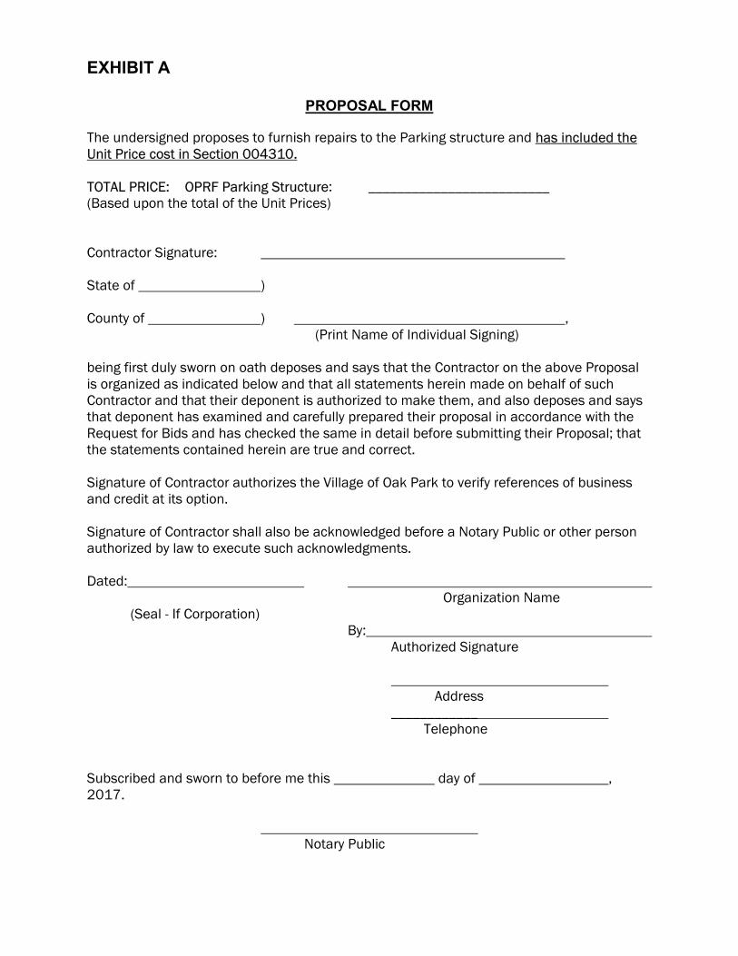
EXHIBIT A
PROPOSAL FORM
The undersigned proposes to furnish repairs to the Parking structure and has included the Unit Price cost in Section 004310. TOTAL PRICE: OPRF Parking Structure: _________________________ (Based upon the total of the Unit Prices) Contractor Signature: State of ) County of ) , (Print Name of Individual Signing) being first duly sworn on oath deposes and says that the Contractor on the above Proposal is organized as indicated below and that all statements herein made on behalf of such Contractor and that their deponent is authorized to make them, and also deposes and says that deponent has examined and carefully prepared their proposal in accordance with the Request for Bids and has checked the same in detail before submitting their Proposal; that the statements contained herein are true and correct. Signature of Contractor authorizes the Village of Oak Park to verify references of business and credit at its option. Signature of Contractor shall also be acknowledged before a Notary Public or other person authorized by law to execute such acknowledgments. Dated:
Organization Name (Seal - If Corporation)
By: Authorized Signature Address ____________ Telephone Subscribed and sworn to before me this day of , 2017. Notary Public

Page 14 of 12 Village of Oak Park
In the State of . My Commission Expires: .
[THIS SPACE LEFT INTENTIONALLY BLANK]

EXHIBIT B
ORGANIZATION OF CONTRACTING FIRM
Please fill out the applicable section: A. Corporation: The Contractor is a corporation, legally named _________________________________ and is organized and existing in good standing under the laws of the State of ____________. The full names of its Officers are:
President Secretary Treasurer
Registered Agent Name and Address: The corporation has a corporate seal. (In the event that this Bid is executed by a person other than the President, attach hereto a certified copy of that section of Corporate By-Laws or other authorization by the Corporation that permits the person to execute the offer for the corporation.) B. Sole Proprietor: The Contractor is a Sole Proprietor. If the Contractor does business under an Assumed Name, the Assumed Name is , which is registered with the Cook County Clerk. The Contractor is otherwise in compliance with the Assumed Business Name Act, 805 ILCS 405/0.01, et. seq. C. Partnership: The Contractor is a Partnership which operates under the name _____ The following are the names, addresses and signatures of all partners: Signature Signature (Attach additional sheets if necessary.) If so, check here .
If the partnership does business under an assumed name, the assumed name must be registered with the Cook County Clerk and the partnership is otherwise in compliance with the Assumed Business Name Act, 805 ILCS 405/0.01, et. seq. D. Affiliates: The name and address of any affiliated entity of the business, including a description of the affiliation: Signature of Village
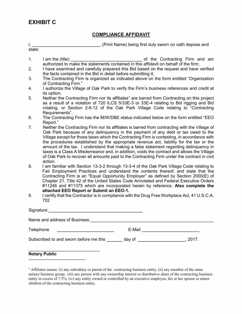
EXHIBIT C
COMPLIANCE AFFIDAVIT
I, , (Print Name) being first duly sworn on oath depose and state: 1. I am the (title) of the Contracting Firm and am
authorized to make the statements contained in this affidavit on behalf of the firm; 2. I have examined and carefully prepared this Bid based on the request and have verified
the facts contained in the Bid in detail before submitting it; 3. The Contracting Firm is organized as indicated above on the form entitled “Organization
of Contracting Firm.” 4. I authorize the Village of Oak Park to verify the Firm’s business references and credit at
its option; 5. Neither the Contracting Firm nor its affiliates1 are barred from Contracting on this project
as a result of a violation of 720 ILCS 5/33E-3 or 33E-4 relating to Bid rigging and Bid rotating, or Section 2-6-12 of the Oak Park Village Code relating to “Contracting Requirements”.
6. The Contracting Firm has the M/W/DBE status indicated below on the form entitled “EEO Report.”
7. Neither the Contracting Firm nor its affiliates is barred from contracting with the Village of Oak Park because of any delinquency in the payment of any debt or tax owed to the Village except for those taxes which the Contracting Firm is contesting, in accordance with the procedures established by the appropriate revenue act, liability for the tax or the amount of the tax. I understand that making a false statement regarding delinquency in taxes is a Class A Misdemeanor and, in addition, voids the contract and allows the Village of Oak Park to recover all amounts paid to the Contracting Firm under the contract in civil action.
8. I am familiar with Section 13-3-2 through 13-3-4 of the Oak Park Village Code relating to Fair Employment Practices and understand the contents thereof; and state that the Contracting Firm is an “Equal Opportunity Employer” as defined by Section 2000(E) of Chapter 21, Title 42 of the United States Code Annotated and Federal Executive Orders #11246 and #11375 which are incorporated herein by reference. Also complete the attached EEO Report or Submit an EEO-1.
9. I certify that the Contractor is in compliance with the Drug Free Workplace Act, 41 U.S.C.A, 702
Signature: Name and address of Business: Telephone E-Mail Subscribed to and sworn before me this day of , 2017. Notary Public
1 Affiliates means: (i) any subsidiary or parent of the contracting business entity, (ii) any member of the same
unitary business group; (iii) any person with any ownership interest or distributive share of the contracting business
entity in excess of 7.5%; (iv) any entity owned or controlled by an executive employee, his or her spouse or minor
children of the contracting business entity.

EXHIBIT D
M/W/DBE STATUS
Failure to respond truthfully to any questions on this form, failure to complete the form or failure to cooperate fully with further inquiry by the Village of Oak Park will result in disqualification of this RFP. For assistance in completing this form, contact the Department of Parking and Mobility Services at 708-358-7275, Ext 6759. 1. Contractor Name: 2. Check here if your firm is:
� Minority Business Enterprise (MBE) (A firm that is at least 51% owned, managed and controlled by a Minority.)
� Women’s Business Enterprise (WBE) (A firm that is at least 51% owned, managed and controlled by a Woman.)
� Owned by a person with a disability (DBE) (A firm that is at least 51% owned by a person with a disability)
� None of the above
[Submit copies of any W/W/DBE certifications] 3. What is the size of the firm’s current stable work force? Number of full-time employees Number of part-time employees 4. Similar information will be requested of all sub-Contractors working on this contract.
Forms will be furnished to the lowest responsible Contractor with the notice of contract award, and these forms must be completed and submitted to the Village before the execution of the contract by the Village.
Signature: ___ ___________________ Date: __________________
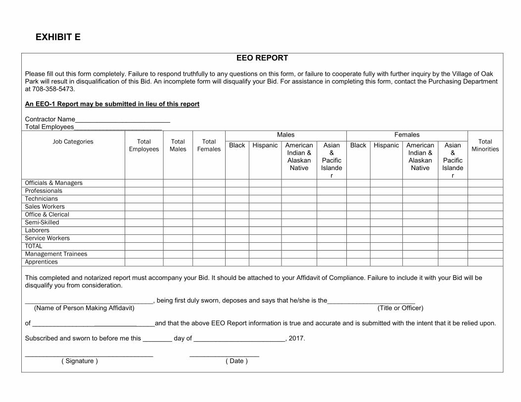
EXHIBIT E
EEO REPORT
Please fill out this form completely. Failure to respond truthfully to any questions on this form, or failure to cooperate fully with further inquiry by the Village of Oak Park will result in disqualification of this Bid. An incomplete form will disqualify your Bid. For assistance in completing this form, contact the Purchasing Department at 708-358-5473. An EEO-1 Report may be submitted in lieu of this report
Contractor Name__________________________ Total Employees________________________
Job Categories
Total
Employees
Total
Males
Total
Females
Males Females Total
Minorities Black Hispanic American
Indian & Alaskan Native
Asian &
Pacific Islande
r
Black Hispanic American Indian & Alaskan Native
Asian &
Pacific Islande
r Officials & Managers
Professionals
Technicians
Sales Workers
Office & Clerical
Semi-Skilled
Laborers
Service Workers
TOTAL
Management Trainees
Apprentices
This completed and notarized report must accompany your Bid. It should be attached to your Affidavit of Compliance. Failure to include it with your Bid will be disqualify you from consideration. ___________________________________, being first duly sworn, deposes and says that he/she is the________________________ (Name of Person Making Affidavit) (Title or Officer) of _________________ _____and that the above EEO Report information is true and accurate and is submitted with the intent that it be relied upon. Subscribed and sworn to before me this ________ day of _________________________, 2017. ___________________________________ ___________________ ( Signature ) ( Date )
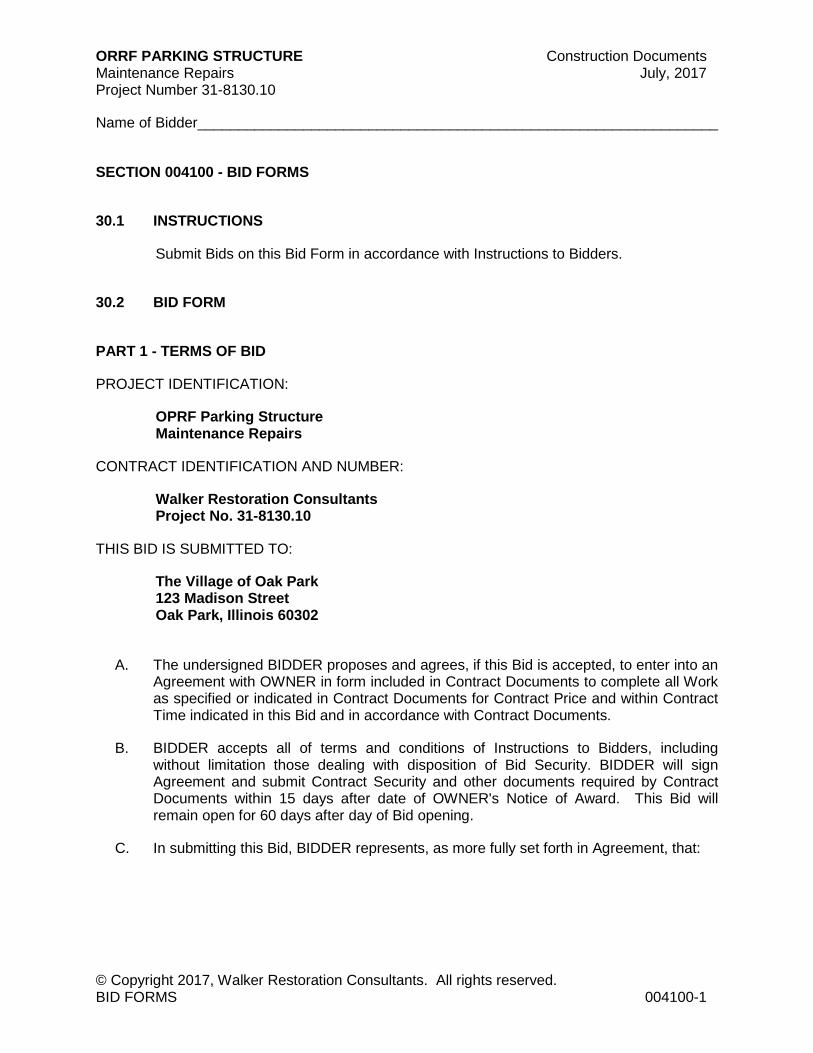
ORRF PARKING STRUCTURE Construction Documents Maintenance Repairs July, 2017 Project Number 31-8130.10
Name of Bidder________________________________________________________________
© Copyright 2017, Walker Restoration Consultants. All rights reserved. BID FORMS 004100-1
SECTION 004100 - BID FORMS
30.1 INSTRUCTIONS
Submit Bids on this Bid Form in accordance with Instructions to Bidders.
30.2 BID FORM
PART 1 - TERMS OF BID
PROJECT IDENTIFICATION:
OPRF Parking Structure Maintenance Repairs
CONTRACT IDENTIFICATION AND NUMBER:
Walker Restoration Consultants Project No. 31-8130.10
THIS BID IS SUBMITTED TO:
The Village of Oak Park 123 Madison Street Oak Park, Illinois 60302
A. The undersigned BIDDER proposes and agrees, if this Bid is accepted, to enter into an Agreement with OWNER in form included in Contract Documents to complete all Work as specified or indicated in Contract Documents for Contract Price and within Contract Time indicated in this Bid and in accordance with Contract Documents.
B. BIDDER accepts all of terms and conditions of Instructions to Bidders, including without limitation those dealing with disposition of Bid Security. BIDDER will sign Agreement and submit Contract Security and other documents required by Contract Documents within 15 days after date of OWNER's Notice of Award. This Bid will remain open for 60 days after day of Bid opening.
C. In submitting this Bid, BIDDER represents, as more fully set forth in Agreement, that:

ORRF PARKING STRUCTURE Construction Documents Maintenance Repairs July, 2017 Project Number 31-8130.10
Name of Bidder________________________________________________________________
© Copyright 2017, Walker Restoration Consultants. All rights reserved. BID FORMS 004100-2
1. BIDDER has examined copies of all Contract Documents and of following addenda:
Date Number
(receipt of all of which is hereby acknowledged) and also copies of Advertisement or Invitation to Bid or Instructions to Bidders.
2. BIDDER has examined site and locality where Work is to be performed, legal requirements (federal, state and local laws, ordinances, rules and regulations) and conditions affecting cost, progress or performance of Work and has made such independent investigations as BIDDER deems necessary.
3. This Bid is genuine and not made in interest of or on behalf of any undisclosed person, firm or corporation and is not submitted in conformity with any agreement or rules of any group, association, organization or corporation; BIDDER has not directly induced or solicited any other Bidder to submit false or sham Bid; BIDDER has not solicited or induced any person, firm or corporation to refrain from bidding; and BIDDER has not sought by collusion to obtain for itself any advantage over any other Bidder or over OWNER; and
4. BIDDER agrees that Work Item quantities are estimates and that OWNER may increase or decrease these quantities at unit prices stated, so long as increases or decreases in Base Bid do not exceed 25% of Base Bid price. Increases or decreases beyond these limits shall be in accordance with Supplementary Conditions, Section 007300.
5. BIDDER agrees that all alterations or additions to Work shall be performed in accordance with paragraph “Changes” and/or “Construction Change Directives” under Section "Supplementary Conditions."
6. OWNER reserves right to delete any section of Work.
D. BIDDER agrees that Work shall be completed in a timely fashion according to the proposed schedule laid out.
E. BIDDER will complete Work for following price based on unit prices stated in Section 004310:
LUMP SUM CONTRACT PRICE __________________________________________ (use words)
________________________________DOLLARS $ __________________________ (figures)
ORRF PARKING STRUCTURE Construction Documents Maintenance Repairs July, 2017 Project Number 31-8130.10
Name of Bidder________________________________________________________________
© Copyright 2017, Walker Restoration Consultants. All rights reserved. BID FORMS 004100-3
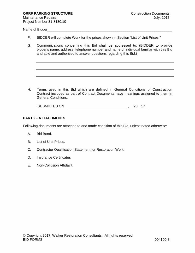
F. BIDDER will complete Work for the prices shown in Section "List of Unit Prices."
G. Communications concerning this Bid shall be addressed to: (BIDDER to provide bidder’s name, address, telephone number and name of individual familiar with this Bid and able and authorized to answer questions regarding this Bid.)
H. Terms used in this Bid which are defined in General Conditions of Construction Contract included as part of Contract Documents have meanings assigned to them in General Conditions.
SUBMITTED ON
, 20 17
PART 2 - ATTACHMENTS
Following documents are attached to and made condition of this Bid, unless noted otherwise:
A. Bid Bond.
B. List of Unit Prices.
C. Contractor Qualification Statement for Restoration Work.
D. Insurance Certificates
E. Non-Collusion Affidavit.
ORRF PARKING STRUCTURE Construction Documents Maintenance Repairs July, 2017 Project Number 31-8130.10
Name of Bidder________________________________________________________________
© Copyright 2017, Walker Restoration Consultants. All rights reserved. BID FORMS 004100-4
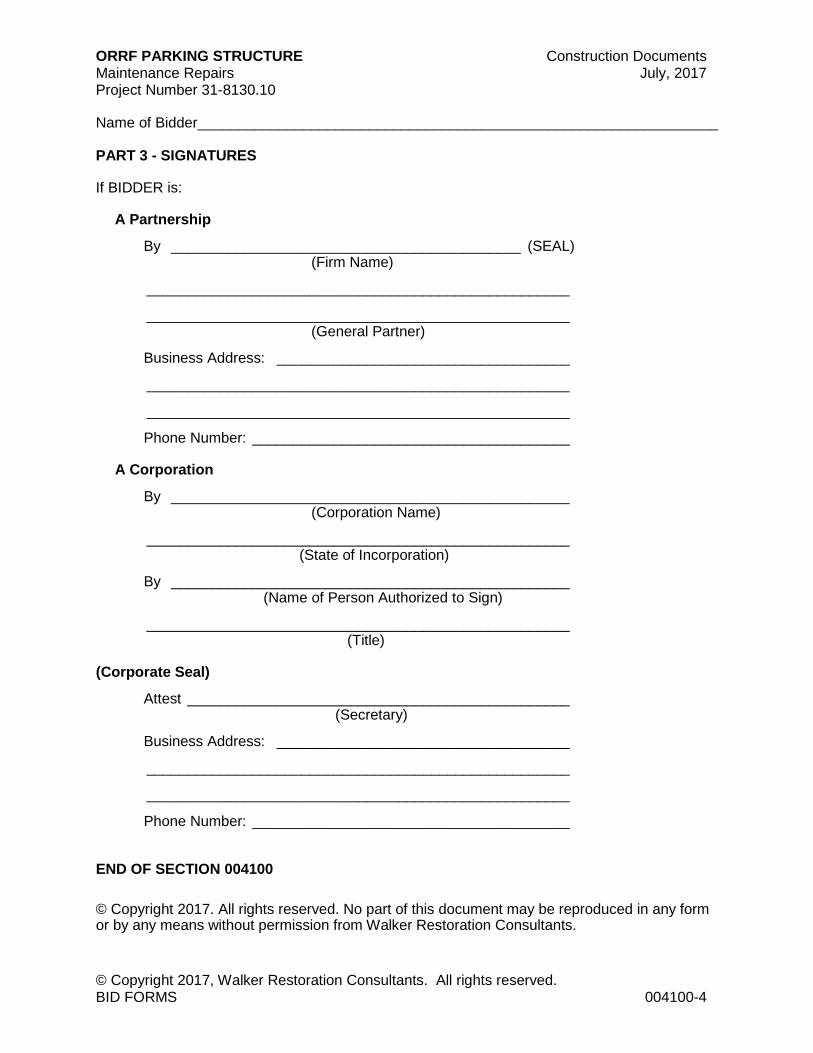
PART 3 - SIGNATURES
If BIDDER is:
A Partnership
By ___________________________________________ (SEAL) (Firm Name)
____________________________________________________
____________________________________________________ (General Partner)
Business Address: ____________________________________
____________________________________________________
____________________________________________________
Phone Number: _______________________________________
A Corporation
By _________________________________________________ (Corporation Name)
____________________________________________________ (State of Incorporation)
By _________________________________________________ (Name of Person Authorized to Sign)
____________________________________________________ (Title)
(Corporate Seal)
Attest _______________________________________________ (Secretary)
Business Address: ____________________________________
____________________________________________________
____________________________________________________
Phone Number: _______________________________________
END OF SECTION 004100
© Copyright 2017. All rights reserved. No part of this document may be reproduced in any form or by any means without permission from Walker Restoration Consultants.
ORRF PARKING STRUCTURE Construction Documents Maintenance Repairs July, 2017 Project Number 31-8130.10
Name of Bidder_______________________________________________________________
© Copyright 2017, Walker Restoration Consultants. All rights reserved. PROCUREMENT FORM SUPPLEMENTS 004310-1
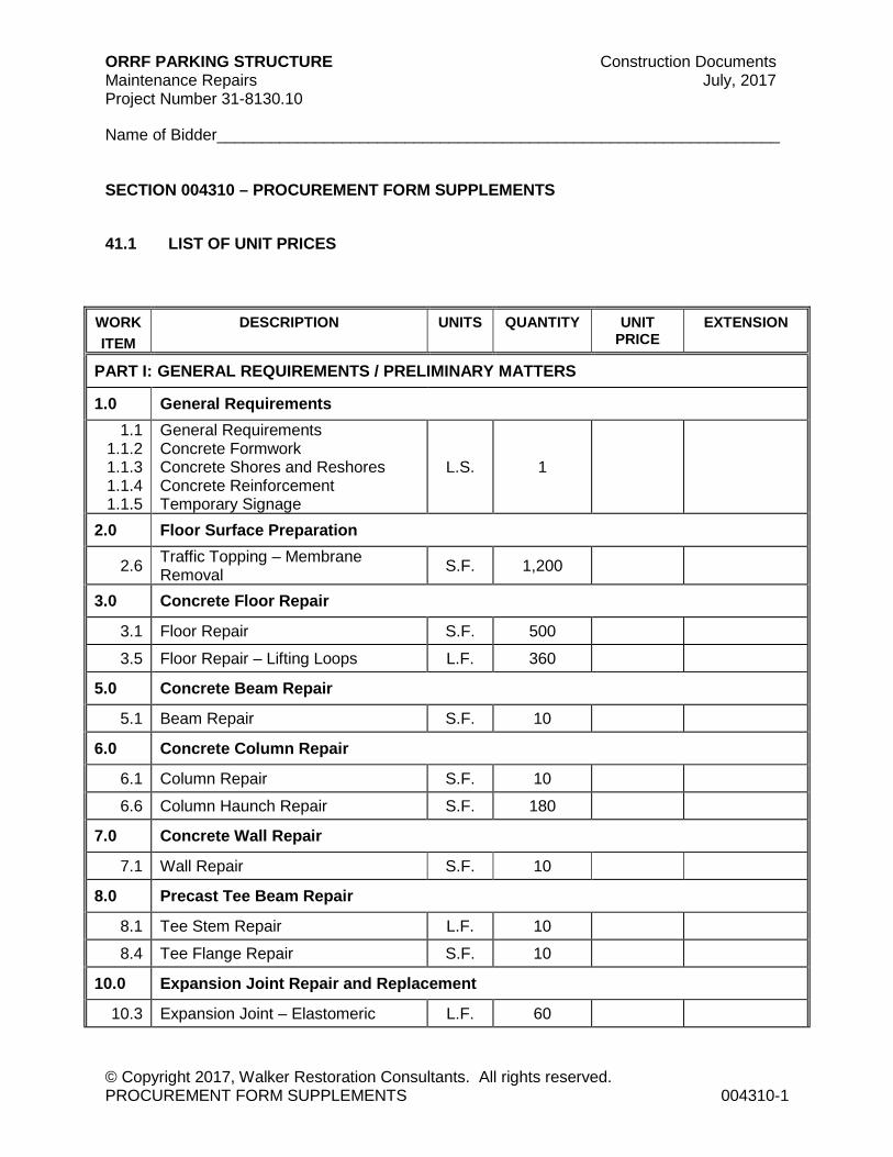
SECTION 004310 – PROCUREMENT FORM SUPPLEMENTS
41.1 LIST OF UNIT PRICES
WORK
ITEM
DESCRIPTION UNITS QUANTITY UNIT
PRICE EXTENSION
PART I: GENERAL REQUIREMENTS / PRELIMINARY MATTERS
1.0 General Requirements
1.1 1.1.2 1.1.3 1.1.4 1.1.5
General Requirements Concrete Formwork Concrete Shores and Reshores Concrete Reinforcement Temporary Signage
L.S. 1
2.0 Floor Surface Preparation
2.6 Traffic Topping – Membrane Removal
S.F. 1,200
3.0 Concrete Floor Repair
3.1 Floor Repair S.F. 500
3.5 Floor Repair – Lifting Loops L.F. 360
5.0 Concrete Beam Repair
5.1 Beam Repair S.F. 10
6.0 Concrete Column Repair
6.1 Column Repair S.F. 10
6.6 Column Haunch Repair S.F. 180
7.0 Concrete Wall Repair
7.1 Wall Repair S.F. 10
8.0 Precast Tee Beam Repair
8.1 Tee Stem Repair L.F. 10
8.4 Tee Flange Repair S.F. 10
10.0 Expansion Joint Repair and Replacement
10.3 Expansion Joint – Elastomeric L.F. 60
ORRF PARKING STRUCTURE Construction Documents Maintenance Repairs July, 2017 Project Number 31-8130.10
Name of Bidder_______________________________________________________________
© Copyright 2017, Walker Restoration Consultants. All rights reserved. PROCUREMENT FORM SUPPLEMENTS 004310-2
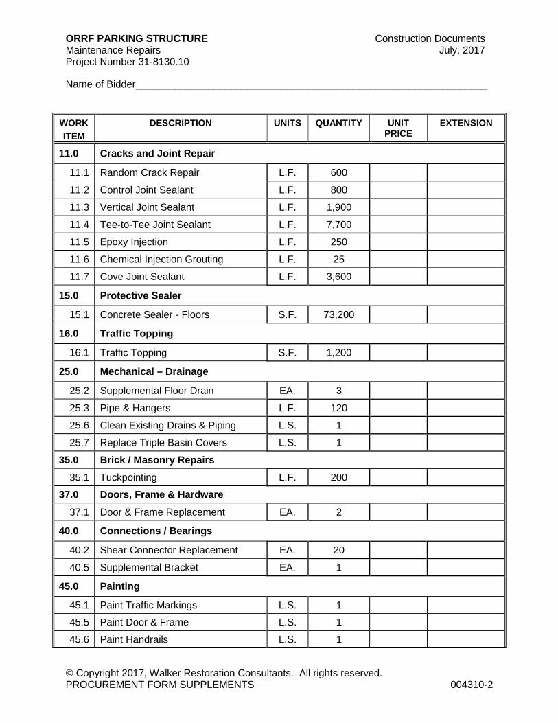
WORK
ITEM
DESCRIPTION UNITS QUANTITY UNIT
PRICE EXTENSION
11.0 Cracks and Joint Repair
11.1 Random Crack Repair L.F. 600
11.2 Control Joint Sealant L.F. 800
11.3 Vertical Joint Sealant L.F. 1,900
11.4 Tee-to-Tee Joint Sealant L.F. 7,700
11.5 Epoxy Injection L.F. 250
11.6 Chemical Injection Grouting L.F. 25
11.7 Cove Joint Sealant L.F. 3,600
15.0 Protective Sealer
15.1 Concrete Sealer - Floors S.F. 73,200
16.0 Traffic Topping
16.1 Traffic Topping S.F. 1,200
25.0 Mechanical – Drainage
25.2 Supplemental Floor Drain EA. 3
25.3 Pipe & Hangers L.F. 120
25.6 Clean Existing Drains & Piping L.S. 1
25.7 Replace Triple Basin Covers L.S. 1
35.0 Brick / Masonry Repairs
35.1 Tuckpointing L.F. 200
37.0 Doors, Frame & Hardware
37.1 Door & Frame Replacement EA. 2
40.0 Connections / Bearings
40.2 Shear Connector Replacement EA. 20
40.5 Supplemental Bracket EA. 1
45.0 Painting
45.1 Paint Traffic Markings L.S. 1
45.5 Paint Door & Frame L.S. 1
45.6 Paint Handrails L.S. 1

ORRF PARKING STRUCTURE Construction Documents Maintenance Repairs July, 2017 Project Number 31-8130.10
Name of Bidder_______________________________________________________________
© Copyright 2017, Walker Restoration Consultants. All rights reserved. PROCUREMENT FORM SUPPLEMENTS 004310-3
WORK
ITEM
DESCRIPTION UNITS QUANTITY UNIT
PRICE EXTENSION
45.7 Paint Steel Stairs L.S. 1
45.8 Paint Structural Steel L.S. 1
45.9 Paint Guard Railing L.S. 1
74.0 Façade Joint and Sealant Repair
74.7 Capstone Joint Repair L.F. 1,500
83.0 Concrete / Cast Stone Façade
83.6 Precast Panel Repair L.S. 1
91.0 Façade Coating
91.5 Elastomeric Coating S.F. 2,200
96.0 Roofing and Coping
96.4 Replace Single Ply Roofing EA. 2
GRAND TOTAL $___________
Description of Abbreviations:
EA. = Each L.F. = Lineal Feet L.S. = Lump Sum S.F. = Square Feet

ORRF PARKING STRUCTURE Construction Documents Maintenance Repairs July, 2017 Project Number 31-8130.10
Name of Bidder_______________________________________________________________
© Copyright 2017, Walker Restoration Consultants. All rights reserved. PROCUREMENT FORM SUPPLEMENTS 004310-4
41.2 NON-COLLUSION AFFIDAVIT
Bidder, by its officers and its agents or representatives present at the time of filing this Bid, being duly sworn on their oaths say, that neither they nor any of them have in any way, directly or indirectly, entered into any arrangement or agreement with any other Bidder, or with any officer of the Village of Oak Park whereby such affiant or affiants or either of them has paid or is to pay such other Bidder or officer any sum of money, or has given or is to give to such other Bidder or officer anything of value whatever, or such affiant or affiants or either of them has not directly or indirectly, entered into any arrangement or agreement with any other free competition into the letting of the contract sought for by the attached Bids that no inducement of any form or character other than that which appears on the face of the Bid will be suggested, offered, paid or delivered to any person whomsoever to influence the acceptance of the Bid or awarding of the Contract, nor has this Bidder any agreement or understanding of any kind whatsoever, with any person whomsoever to pay, deliver to, or share with any other person in any way or manner, any of the proceeds of the Contractor sought by this Bid.
Submitted By:
Type or print firm name:
________________________________________________________________
Authorized Signature:
________________________________________________________________
Date:
_____________________________
END OF SECTION 004310
© Copyright 2017. All rights reserved. No part of this document may be reproduced in any form or by any means without permission from Walker Restoration Consultants.

ORRF PARKING STRUCTURE Construction Documents Maintenance Repairs July, 2017 Project Number 31-8130.10
© Copyright 2017, Walker Restoration Consultants. All rights reserved. CONTRACTOR'S QUALIFICATION STATEMENT 005000-1
SECTION 005000 - CONTRACTOR'S QUALIFICATION STATEMENT
This statement is required for consideration of the restoration contract for the Village of Oak Park – OPRF Parking Structure Maintenance Repairs.
SUBMITTED TO: WALKER Restoration Consultants 505 Davis Road Elgin, Illinois 60123 Attn: Larry Susmarski
SUBMITTED BY: _________________________________________
ADDRESS: __________________________________________
__________________________________________
PHONE: ( ) ____________________________________
CONTACT: __________________________________________
COMPANY STRUCTURE: SPECIAL CERTIFICATIONS: Corporation MBE Partnership WBE Individual Other (Explain): Joint Venture Other (Explain)
______________________________________________________
______________________________________________________
SUBMITTAL DATE: _________________________________________________
AREA(S) OF EXPERTISE: (Check all that apply) Structural Concrete Repair Concrete Flatwork Waterproofing/Joints & Sealants Brick/Masonry Waterproofing/Traffic Toppings & Sealers Historic Buildings Waterproofing/Roofing Waterproofing/Plaza Systems

ORRF PARKING STRUCTURE Construction Documents Maintenance Repairs July, 2017 Project Number 31-8130.10
© Copyright 2017, Walker Restoration Consultants. All rights reserved. CONTRACTOR'S QUALIFICATION STATEMENT 005000-2
CONTRACTOR'S QUALIFICATION QUESTIONNAIRE
1. How many years has your organization been in business as a restoration contractor? Starting Year:
2. How many years has your organization been in business as a restoration contractor? Starting Year:
3. How many years has your organization been in business under its present business name? Starting Year:
4. List states in which your organization is legally qualified to do business.
5. What percentage of the work do you normally perform with your own work forces?
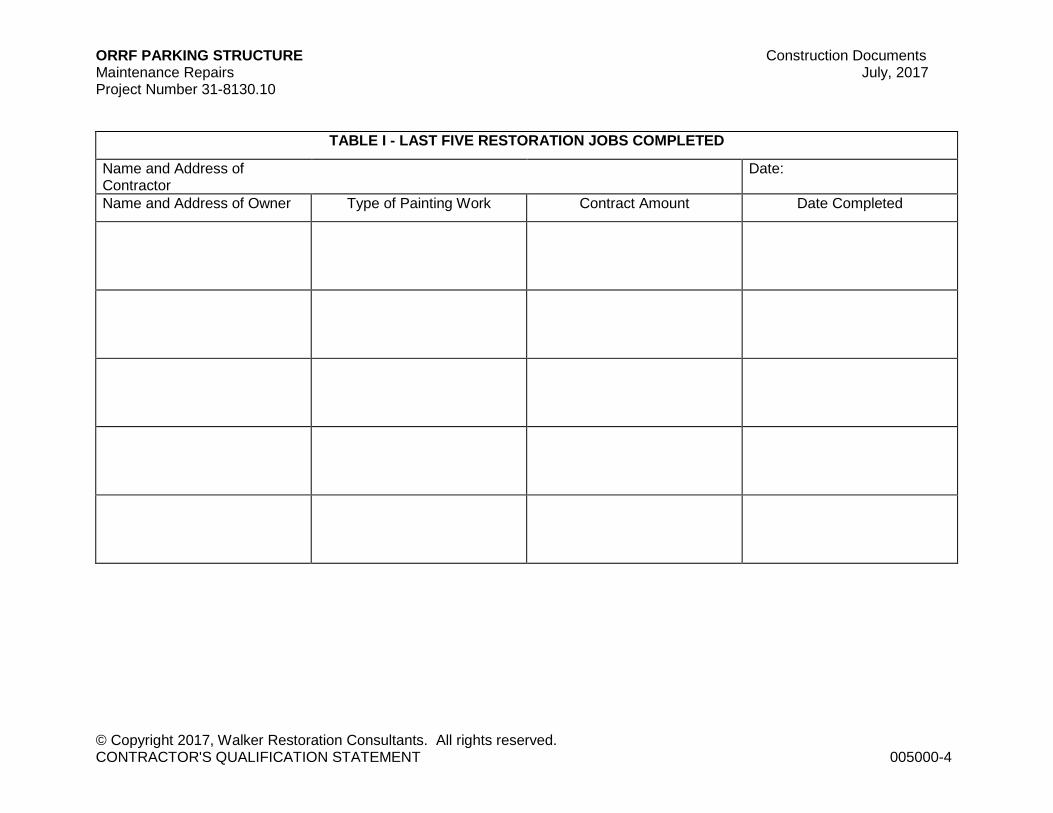
6. List on Table I the last five painting projects your firm has completed.
7. List on Table II the painting projects your organization has in progress at this time.
8. Have you ever failed to complete any work awarded to you? If so, attach a separate sheet of explanation.
9. Has any officer or partner of your organization ever been an officer or partner of another organization that failed to complete a painting contract? If so, attach a separate sheet of explanation.
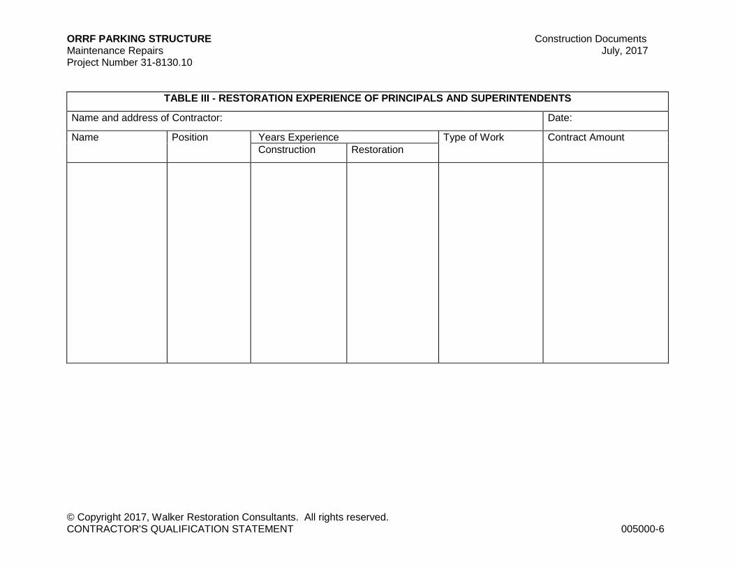
10. List on Table III the painting experience of the principals and superintendents of your company.
11. What is your present bonding capacity? $ per Project,
$ Aggregate
12. Who is your bonding agent?
NAME: _________________________________________________
ADDRESS: _________________________________________________
PHONE: ( ) ___________________________________________
CONTACT: _________________________________________________
13. Are you rated by any State Highway Departments? If so, please list which states on Table IV and your company's rating.
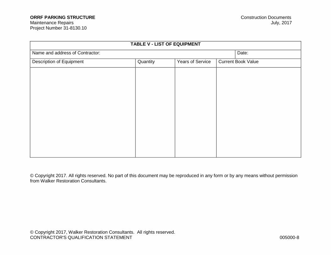
14. List on Table V the equipment you own that is available for painting work.
15. Are there any liens against the above? If so, total amount $

ORRF PARKING STRUCTURE Construction Documents Maintenance Repairs July, 2017 Project Number 31-8130.10
© Copyright 2017, Walker Restoration Consultants. All rights reserved. CONTRACTOR'S QUALIFICATION STATEMENT 005000-3
16. Attach your company's most recent audited Balance Sheet, prepared in accordance with generally accepted accounting principles.
Date of Balance Sheet: __________________________________________
Name of firm Balance Sheet: _____________________________________
DATED AT THIS DAY OF , 2017.
Name of Organization: __________________________________________
By: _______________________________________________________
TITLE: ____________________________________________________
STATE OF: ________________________________________________
COUNTY OF: ______________________________________________
being duly sworn, deposes and says that he/she is of the above organization and that the answers to the questions in the foregoing questionnaire and all statements therein contained are true and correct.
SUBSCRIBING AND SWORN TO BEFORE ME THIS DAY OF 2017.
NOTARY PUBLIC: _________________________________________________
MY COMMISSION EXPIRES: _______________________________________
ORRF PARKING STRUCTURE Construction Documents Maintenance Repairs July, 2017 Project Number 31-8130.10
© Copyright 2017, Walker Restoration Consultants. All rights reserved. CONTRACTOR'S QUALIFICATION STATEMENT 005000-4
TABLE I - LAST FIVE RESTORATION JOBS COMPLETED
Name and Address of Contractor
Date:
Name and Address of Owner Type of Painting Work Contract Amount Date Completed

ORRF PARKING STRUCTURE Construction Documents Maintenance Repairs July, 2017 Project Number 31-8130.10
© Copyright 2017, Walker Restoration Consultants. All rights reserved. CONTRACTOR'S QUALIFICATION STATEMENT 005000-5
TABLE II - LIST OF RESTORATION PROJECTS IN PROGRESS
Name and Address of Contractor
Date:
Name and Address of Owner Type of Work Contract Amount Expected Completion Date
ORRF PARKING STRUCTURE Construction Documents Maintenance Repairs July, 2017 Project Number 31-8130.10
© Copyright 2017, Walker Restoration Consultants. All rights reserved. CONTRACTOR'S QUALIFICATION STATEMENT 005000-6
TABLE III - RESTORATION EXPERIENCE OF PRINCIPALS AND SUPERINTENDENTS
Name and address of Contractor: Date:
Name Position Years Experience Type of Work Contract Amount
Construction Restoration

ORRF PARKING STRUCTURE Construction Documents Maintenance Repairs July, 2017 Project Number 31-8130.10
© Copyright 2017, Walker Restoration Consultants. All rights reserved. CONTRACTOR'S QUALIFICATION STATEMENT 005000-7
TABLE IV - RATINGS BY THE STATE OF ILLINOIS DEPARTMENTS
Name and address of Contractor: Date:
State Rating Contact & Phone No. Highway Jobs for Ea. State
ORRF PARKING STRUCTURE Construction Documents Maintenance Repairs July, 2017 Project Number 31-8130.10
© Copyright 2017, Walker Restoration Consultants. All rights reserved. CONTRACTOR'S QUALIFICATION STATEMENT 005000-8
TABLE V - LIST OF EQUIPMENT
Name and address of Contractor: Date:
Description of Equipment Quantity Years of Service Current Book Value
© Copyright 2017. All rights reserved. No part of this document may be reproduced in any form or by any means without permission from Walker Restoration Consultants.

ORRF PARKING STRUCTURE Construction Documents Maintenance Repairs July, 2017 Project Number 31-8130.10
© Copyright 2017, Walker Restoration Consultants. All rights reserved. GENERAL CONDITIONS 007200 - 1
CONDITIONS OF THE CONTRACT
SECTION 007200 - GENERAL CONDITIONS
PART 1 - GENERAL
1.1 AIA Document A201-2007, "GENERAL CONDITIONS OF THE CONTRACT FOR CONSTRUCTION," Articles 1 through 15 inclusive, is hereby made part of Contract Documents.
1.2 Contractor may purchase copies of Agreement Form from The American Institute of Architects, 1735 New York Avenue, N.W., Washington, DC 20006.
1.3 Supplementary Conditions, Section 007300, shall amend or supplement General Conditions. All provisions of General Conditions not amended or supplemented by Supplementary Conditions remain in full force and effect.
END OF SECTION 007200
© Copyright 2017. All rights reserved. No part of this document may be reproduced in any form or by any means without permission from Walker Restoration Consultants.

ORRF PARKING STRUCTURE Construction Documents Maintenance Repairs July, 2017 Project Number 31-8130.10
© Copyright 2017, Walker Restoration Consultants. All rights reserved. SUPPLEMENTARY CONDITIONS 007300 - 1
SECTION 007300 - SUPPLEMENTARY CONDITIONS
PART 1 - GENERAL
1.1 The following supplements modify AIA Document A201–2007, General Conditions of the Contract for Construction. Where a portion of the General Conditions is modified or deleted by these Supplementary Conditions, the unaltered portions of the General Conditions shall remain in effect.
1.2 SC-1.1 BASIC DEFINITIONS
A. Add the following to 1.1.4 - THE PROJECT
The Term Project as used herein shall mean:
OPRF PARKING STRUCTURE Maintenance Repairs
B. Add the following to 1.1.7 – INSTRUMENTS OF SERVICE
The Term Project Manual as used herein shall mean: A volume assembled for the Work which may include the bidding requirements, sample forms, Conditions of the Contract and Specifications.
C. 1.1.9 ENGINEER
Terms Engineer and Architect as used herein shall be synonymous. Term Engineer as used herein shall mean:
WALKER RESTORATION CONSULTANTS 505 Davis Road Elgin, IL 60123
D. 1.1.10 UNIT PRICE WORK
Unit Price Work is Work to be paid for on basis of unit prices.
1.3 SC-1.2. CORRELATION AND INTENT OF THE CONTRACT DOCUMENTS
Add following subparagraphs 1.2.5 to 1.2:
1.2.5 - Reference to standard specifications, manuals, or codes of any technical society, organization, or association, or to laws or regulations of any governmental authority, whether such reference be specific or by implication, shall mean latest standard specification, manual, code, laws, or regulations in effect at time of opening of Bids (or, on Effective Date of Agreement if no Bids), except as may be otherwise specifically stated. However, no provision of any referenced standard specification,

ORRF PARKING STRUCTURE Construction Documents Maintenance Repairs July, 2017 Project Number 31-8130.10
© Copyright 2017, Walker Restoration Consultants. All rights reserved. SUPPLEMENTARY CONDITIONS 007300 - 2
manual, or code (whether or not specifically incorporated by reference in Contract Documents) shall be effective to change duties and responsibilities of Owner, Contractor, or Architect, or any of their consultants, agents, or employees from those set forth in Contract Documents, nor shall be effective to assign to Architect, or any of Architect's consultants, agents, or employees, any duty or authority to supervise or direct furnishing or performance of Work, or any duty or authority to undertake responsibility contrary to General Conditions.
1.4 SC-2.1 GENERAL
Add following to 2.1.1: The Owner’s shall mean:
VILLAGE OF OAK PARK 123 Madison Street Oak Park, IL 60302
1.5 SC-2.2 INFORMATION AND SERVICES REQUIRED OF THE OWNER Delete subparagraph 2.2.5 and substitute following:
2.2.5 - The Owner shall furnish the Contractor 1 hard copy of the Contract Documents, plus a pdf version of the drawings and specifications. The Contractor may purchase additional copies at cost of reproduction, postage and handling.
1.6 SC-3.4 LABOR AND MATERIALS
Add following to 3.4.1:
All materials and equipment shall be applied, installed, connected, erected, used, cleaned, and conditioned in accordance with instructions of applicable supplier except as otherwise provided in Contract Documents; but no provisions of any such instructions will be effective to assign to Architect, or any of Architect's consultants, agents, or employees any duty or authority to undertake responsibility contrary to General Conditions.
Add following subparagraphs 3.4.4, 3.4.5, and 3.4.6 to 3.4:
3.4.4 - After Contract has been executed, Owner and Architect will consider formal request for substitution of products in place of those specified only under conditions set forth in General Requirements (Division 1 of Specifications).
3.4.5 - By making requests for substitutions based on subparagraph 3.4.3 above, Contractor:
1. Represents that Contractor has personally investigated proposed substitute product and determined that it is equal or superior in all respects to that specified.
ORRF PARKING STRUCTURE Construction Documents Maintenance Repairs July, 2017 Project Number 31-8130.10
© Copyright 2017, Walker Restoration Consultants. All rights reserved. SUPPLEMENTARY CONDITIONS 007300 - 3
2. Represents that Contractor will provide same warranty for substitution that Contractor would for that specified.
3. Certifies that cost data presented is complete and includes all related costs under this Contract except Architect's redesign costs, and waives all claims for additional costs related to substitution which subsequently become apparent, and
4. Will coordinate installation of accepted substitute, making such changes as may be required for Work to be complete in all respects.
3.4.6 - Architect's decision of approval or disapproval of proposed substitution shall be final.
1.7 SC-3.7 PERMITS, FEES AND NOTICES
Add following to 3.7.2:
Except where otherwise expressly required by applicable laws, ordinances, rules, regulations and lawful orders of public authorities, neither Owner nor Architect shall be responsible for monitoring Contractor's compliance with any applicable law, ordinance, rule, regulation and lawful order of public authorities.
1.8 SC-3.10 CONTRACTOR'S CONSTRUCTION SCHEDULES
Add following to 3.10.2:
If required by Architect, schedule of submittals shall be adjusted to provide workable arrangement for processing submittals.
1.9 SC-3.12 SHOP DRAWINGS, PRODUCT DATA AND SAMPLES
Add the following sentence to subparagraph 3.12.5:
Submittals made by Contractor which are not required by Contract Documents will be returned immediately with notation “Submittal Not Required No Review Performed”.
Add following subparagraphs 3.12.11 through 3.12.17 to 3.12:
3.12.11 - Submission to Architect of Shop Drawings and samples approved by Contractor and review of said Shop Drawings and samples by Architect shall not constitute submission in writing or approval in writing of any deviation from requirements of Contract Documents unless the Contractor has specifically informed the Architect in writing of such deviation at the time of the submittal and the Contractor has received written approval or authorization in accordance with 3.12.8.
3.12.12 - Changes to Drawings and Specifications by means of Shop Drawings become responsibility of party initiating such changes.
ORRF PARKING STRUCTURE Construction Documents Maintenance Repairs July, 2017 Project Number 31-8130.10
© Copyright 2017, Walker Restoration Consultants. All rights reserved. SUPPLEMENTARY CONDITIONS 007300 - 4
3.12.13 - Submission to Architect of Shop Drawings and samples approved by Contractor and review of said Shop Drawings and samples by Architect shall not imply that any requirements of Contract Documents have been waived or superseded.
3.12.14 - No delay or omission to exercise any right or remedy accruing to Architect upon any breach or event of default of Contractor shall impair any such right or remedy to be construed to be waiver of any such breach or default; nor shall any waiver of any single breach or default be deemed waiver of any other, prior, or subsequent breach or default. Any waiver, permit, consent, or approval on part of Architect of any breach or default, or of any provision or condition hereof, must be in writing and shall be effective only to extent that such writing specifically sets forth.
3.12.15 - Architect's stamp on Shop Drawing shall not imply approval of quantities, dimensions, fabrication processes and techniques of construction, all of which shall remain responsibility of Contractor.
3.12.16 - Architect's stamp on Shop Drawing shall not relieve Contractor from responsibility for errors or omissions in Shop Drawing and shall not imply that Contractor may proceed in error.
3.12.17 - Shop Drawings and samples shall be submitted in accordance with procedures of Section 013300.
1.10 SC-3.18 INDEMNIFICATION
Add following subparagraph 3.18.3 to 3.18:
3.18.3 - Contractor shall agree that total aggregate liability for consequential and incidental damages (but not direct damages) suffered with respect to professional negligence associated or connected with Drawings and Specifications from which Contractor Prepared Contract Bid Price and for which Owner, Architect, and their agents or consultants may be liable, shall be limited to amount not to exceed $50,000. Contractor shall further agree that with respect to each subcontractor, Contractor will obtain as condition precedent to subcontractor's performance, agreement that foregoing limitation of liability for consequential and incidental damages (but not direct damages) shall not in aggregate exceed $100,000 for all Contractor's subcontractors. It is understood and agreed between parties hereto that this provision shall be confined in application to only those matters affecting Contract Bid Price and shall not affect any party's liability for personal injury or property damage arising or resulting from sole negligence of any party, its agents or employees.
1.11 SC-4.1 ARCHITECT
Delete first sentence of subparagraph 4.1.1 and replace with following:
Architect is person or entity identified as such in Agreement and is referred to throughout Contract Documents as if singular in number.

ORRF PARKING STRUCTURE Construction Documents Maintenance Repairs July, 2017 Project Number 31-8130.10
© Copyright 2017, Walker Restoration Consultants. All rights reserved. SUPPLEMENTARY CONDITIONS 007300 - 5
1.12 SC-4.2 ADMINISTRATION OF THE CONTRACT
Add following subparagraph 4.2.15 through 4.2.20 to 4.2:
4.2.15 – Architect’s terminology on Shop Drawing review stamp of “NO EXCEPTION TAKEN” shall mean that Architect has reviewed and approved Shop Drawing so stamped only for conformance with design concept of Project as given in Contract Documents.
4.2.16 – Architect’s terminology on Shop Drawing review stamp of “MAKE CORRECTIONS NOTED – RESUBMITTAL NOT REQUIRED” shall mean that Architect has reviewed and approved Shop Drawing so stamped, subject to corrections made on Shop Drawing, only for conformance with design concept of Project as given in Contract Documents.
4.2.17 – Architect’s terminology on Shop Drawing review stamp of “REJECTED” shall mean that Architect has not approved the Shop Drawing so stamped, subject to corrections made on Shop drawing and resubmittal is required.
4.2.18 – Architect’s terminology on Shop Drawing review stamp of “REVISE AND RESUBMIT” shall mean that Architect has reviewed and not approved Shop Drawing, only for conformance with design concept of Project as given in Contract Documents and resubmittal is required.
4.2.19 – Architect’s terminology in Shop Drawing review stamp of “SUBMITTAL NOT REQUIRED NO REVIEW PERFORMED” shall mean that submittal is not required by specification or resubmittal was not required and Architect has not reviewed the shop drawings.
4.2.20 - Unit Prices: Architect will review and approve actual quantities and determine classification of Unit Price Work performed by Contractor. Architect will review Contractor's preliminary determinations on such matters before rendering written decision thereon (by recommendation of Application for Payment or otherwise). Architect's written decisions thereon will be final and binding upon Owner and Contractor, unless, within ten days after date of any such decision, either Owner or Contractor delivers to other party to Agreement and to Architect written notice of intention to appeal from such decision.
1.13 SC-7.1 GENERAL
Add the following subparagraphs 7.1.4 to 7.1:
7.1.4 INCREASED OR DECREASED WORK ITEM QUANTITIES
Engineer shall have right under contract to make increases and decreases in quantities and changes in plans, as may be necessary to ensure completion of contemplated work subject to following qualifications:
ORRF PARKING STRUCTURE Construction Documents Maintenance Repairs July, 2017 Project Number 31-8130.10
© Copyright 2017, Walker Restoration Consultants. All rights reserved. SUPPLEMENTARY CONDITIONS 007300 - 6
As used herein, major item is defined as any item whose total cost, determined by multiplying constructed quantity and contract unit price, is equal to or greater than 5% of original total contract price. All other items are considered minor items and are not subject to unit price adjustment.
Where cost of final work prior to consideration of adjustment is within 5% of original total contract price, or if amount of adjustment is less than $100, or if item is exempted from such adjustment elsewhere in contract, no adjustment in contract unit prices will be considered for any increased or decreased quantities.
Where cost of final work has increased more than 5% of original total contract price prior to consideration of any adjustment, requests for adjustments will be considered on following basis:
1. Where quantity of an item of work required to complete project is not increased nor decreased from original estimate by more than 25%, payment for quantity of said item will be made at contract unit price.
2. Where quantity of any major item of work is increased by more than 25%, then unit price for quantity of that item of work over 125% of original contract quantity will be decreased by 10% of unit price bid.
3. Where quantity of any major item of work is decreased by more than 25%, then adjusted unit price will be obtained by multiplying contract unit price for that item of work by factor obtained as follows:
Factor = 1 + (0.15 (P-C))/C
Where:
P = Contract Quantity
C = Constructed Quantity
In no case shall product of adjusted unit price and number of units of work performed exceed product of contract unit price and 75% of original contract quantity. Neither will unit price be adjusted to more than twice original contract unit price.
4. In special cases where adjustments provided by previous paragraphs in this subsection do not provide equitable remuneration for work required by change in quantities, Engineer may adjust contract unit prices prior to Notice of Award for portion of item affected, if justified by evidence presented by successful Bidder.
1.14 SC-7.3 CONSTRUCTION CHANGE DIRECTIVES
In first sentence of subparagraph 7.3.7, delete words "including, in case of an increase in the Contract Sum, an amount for overhead and profit as set forth in the Agreement, or if no such amount is set forth in the Agreement, a reasonable amount."
ORRF PARKING STRUCTURE Construction Documents Maintenance Repairs July, 2017 Project Number 31-8130.10
© Copyright 2017, Walker Restoration Consultants. All rights reserved. SUPPLEMENTARY CONDITIONS 007300 - 7
Delete Clauses 7.3.7.1 through 7.37.5 and replace with following:
1. Cost of labor, including social security, old age and unemployment insurance, fringe benefits required by agreement or custom, and workers' or workmen's compensation insurance, plus 20% of sum thereof;
2. Cost of materials, supplies and equipment, including cost of transportation, whether incorporated or consumed, plus 15% of sum thereof;
3. Rental costs of machinery and equipment, exclusive of hand tools, whether rented from Contractor or others, plus 15%;
4. Cost of premiums for all bonds and insurance, permit fees, and sales, use or similar taxes related to Work, plus 15% of sum thereof;
5. Compensation as herein provided shall be accepted by Contractor as payment in full for extra Work done on this basis and said percentages shall cover profit, superintendence, general expense, overhead, and use of small tools and equipment for which no rental is allowed.
1.15 SC-9.2 SCHEDULE OF VALUES
Add following subparagraph 9.2.2 to 9.2:
9.2.2 - Progress payments on account of Unit Price Work will be based on number of units completed.
1.16 SC-9.3 APPLICATIONS FOR PAYMENT
Add following sentence to subparagraph 9.3.1:
Form of Application for Payment shall be notarized AIA Document G702, Application and Certification for Payment, supported by AIA Document G703, Continuation Sheet.
Add following clause 9.3.1.3 to 9.3.1:
9.3.1.3 - Until Substantial Completion, Owner shall pay 90 % of amount due Contractor on account of progress payments.
Add following subparagraph 9.3.4 to 9.3:
9.3.4 - Unit Price Work:
1. Where Contract Documents provide that all or part of Work is to be Unit Price Work, initially Contract Sum will be deemed to include for all Unit Price Work amount equal to sum of established unit prices for each separately identified item of Unit Price Work times estimated quantity of each item as indicated in Agreement. Estimated quantities of items of Unit Price Work are not guaranteed
ORRF PARKING STRUCTURE Construction Documents Maintenance Repairs July, 2017 Project Number 31-8130.10
© Copyright 2017, Walker Restoration Consultants. All rights reserved. SUPPLEMENTARY CONDITIONS 007300 - 8
and are solely for purpose of comparison of Bids and determining initial Contract Sum. Review and approval of actual quantities and classifications of Unit Price Work performed by Contractor will be by Architect in accordance with SC-4.2, subparagraph 4.2.15.
2. Each unit price will be deemed to include amount considered by Contractor to be adequate to cover Contractor's overhead and profit for each separately identified item.
3. Where quantity of any item of Unit Price Work performed by Contractor differs materially and significantly from estimated quantity of such item indicated in Agreement and there is no corresponding adjustment with respect to any other item of Work and if Contractor believes Contractor has incurred additional expense as result thereof, Contractor may make claim for increase in Contract Sum in accordance with Article 7 if parties are unable to agree as to amount of any such increase.
1.17 SC-9.8 SUBSTANTIAL COMPLETION
Add following sentence to subparagraph 9.8.5:
Payment shall be sufficient to increase total payments to 90 % of Contract Sum, less such amounts as Architect shall determine for incomplete Work and unsettled claims.
1.18 SC-11.1 CONTRACTOR'S LIABILITY INSURANCE
Add following subparagraphs 11.1.5, 11.1.6, and 11.1.7 to 11.1:
11.1.5 - Contractor shall purchase insurance as follows:
1. Workers' Compensation insurance including Employer's liability to cover employee injuries or disease compensable under Worker's Compensation Statutes of states in which Work is conducted under this Contract; disability benefit laws, if any; or Federal compensation acts such as U.S. Longshoremen or Harbor Workers' Maritime Employment, or Railroad Compensation Act(s), if applicable. Self-insurance plans approved by regulatory authorities in state in which Work on this Project is performed are acceptable.
2. Comprehensive General Liability policy to cover bodily injury to persons other than employees and for damage to tangible property, including loss of use thereof, including following exposures:
a. All premises and operations. b. Explosion, collapse and underground damage. c. Contractor's Protective coverage for independent contractors or
subcontractors employed by him. d. Contractual Liability as required by General Conditions, Clause 11.1.1.7.

ORRF PARKING STRUCTURE Construction Documents Maintenance Repairs July, 2017 Project Number 31-8130.10
© Copyright 2017, Walker Restoration Consultants. All rights reserved. SUPPLEMENTARY CONDITIONS 007300 - 9
e. Usual Personal Injury Liability endorsement with no exclusions pertaining to employment.
f. Products and Completed Operations coverage.
3. Comprehensive Automobile Liability policy to cover bodily injury and property damage arising out of ownership, maintenance, or use of any motor vehicle, including owned, non-owned, and hired vehicles. In light of standard policy provisions concerning (1) loading and unloading and (2) definitions pertaining to motor vehicles licensed for road use versus unlicensed or self-propelled construction equipment, it is strongly recommended that Comprehensive General Liability and Comprehensive Auto Liability be written by same insurance carrier, though not necessarily in one policy.
4. The Contractor to provide insurance naming the Owner as additional insured, consistent with the limits detailed elsewhere in the contract.
5. Contractor shall purchase Builder's Risk-Installation Floater in form acceptable to Owner covering property of Project for full cost of replacement as of time of any loss which shall include, as named insureds, (1) Contractor, (2) all subcontractors, (3) Owner, and Architect, as their respective interests may prove to be at time of loss, covering insurable property which is subject of this Contract, whether in place, stored at job site, stored elsewhere, or in transit at risk of insured(s). Coverage shall be effected on "All Risk" form including, but not limited to, perils of fire, wind, vandalism, collapse, theft, and earthquake, with exclusions normal to cover. Contractor may arrange for such deductibles as it deems to be within its ability to self-assume, but it will be held solely responsible for amount of such deductible and for any coinsurance penalties. Any insured loss shall be adjusted with Owner and Contractor and paid to Owner and Contractor as Trustee for other Insureds.
6. Umbrella or Excess Liability: Owner or its representative may, for certain projects, require limits higher than those stated under "Limits of Liability" below. Contractor is granted option of arranging coverage under single policy for full limit required or by combination of underlying policies with balance provided by Excess or Umbrella Liability policy equal to total limit(s) requested. Umbrella or Excess policy wording shall be at least as broad as primary or underlying policy(ies) and shall apply both to Contractor's general liability and to its automobile liability insurance.
11.1.6 - Limits of Liability: Required limits of liability for insurance coverages required above shall be not less than following:
1. Workers Compensation:
Coverage A: Compensation Statutory Coverage B: Employer's Liability $ 500,000.00
2. Comprehensive General Liability: Bodily Injury: Each Occurrence $ 3,000,000.00 Bodily Injury: Aggregate (Completed Operations) $ 500,000.00
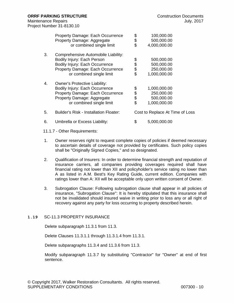
ORRF PARKING STRUCTURE Construction Documents Maintenance Repairs July, 2017 Project Number 31-8130.10
© Copyright 2017, Walker Restoration Consultants. All rights reserved. SUPPLEMENTARY CONDITIONS 007300 - 10
Property Damage: Each Occurrence $ 100,000.00 Property Damage: Aggregate $ 500,000.00 or combined single limit $ 4,000,000.00
3. Comprehensive Automobile Liability: Bodily Injury: Each Person $ 500,000.00 Bodily Injury: Each Occurrence $ 500,000.00 Property Damage: Each Occurrence $ 250,000.00
or combined single limit $ 1,000,000.00
4. Owner's Protective Liability: Bodily Injury: Each Occurrence $ 1,000,000.00 Property Damage: Each Occurrence $ 250,000.00 Property Damage: Aggregate $ 500,000.00
or combined single limit $ 1,000,000.00
5. Builder's Risk - Installation Floater: Cost to Replace At Time of Loss
6. Umbrella or Excess Liability: $ 5,000,000.00
11.1.7 - Other Requirements:
1. Owner reserves right to request complete copies of policies if deemed necessary to ascertain details of coverage not provided by certificates. Such policy copies shall be "Originally Signed Copies," and so designated.
2. Qualification of Insurers: In order to determine financial strength and reputation of insurance carriers, all companies providing coverages required shall have financial rating not lower than XII and policyholder's service rating no lower than A as listed in A.M. Best's Key Rating Guide, current edition. Companies with ratings lower than A: XII will be acceptable only upon written consent of Owner.
3. Subrogation Clause: Following subrogation clause shall appear in all policies of insurance, "Subrogation Clause": It is hereby stipulated that this insurance shall not be invalidated should insured waive in writing prior to loss any or all right of recovery against any party for loss occurring to property described herein.
1.19 SC-11.3 PROPERTY INSURANCE
Delete subparagraph 11.3.1 from 11.3.
Delete Clauses 11.3.1.1 through 11.3.1.4 from 11.3.1.
Delete subparagraphs 11.3.4 and 11.3.6 from 11.3.
Modify subparagraph 11.3.7 by substituting "Contractor" for "Owner" at end of first sentence.
ORRF PARKING STRUCTURE Construction Documents Maintenance Repairs July, 2017 Project Number 31-8130.10
© Copyright 2017, Walker Restoration Consultants. All rights reserved. SUPPLEMENTARY CONDITIONS 007300 - 11
Modify subparagraph 11.3.8 by substituting "Contractor" for "Owner" as fiduciary; except that at first reference to "Owner" in first sentence, word "this" should be substituted for "Owner's."
Modify subparagraph 11.3.9 by substituting "Contractor" for "Owner" each time latter word appears.
Modify subparagraph 11.3.10 by substituting "Contractor" for "Owner" each time latter word appears.
1.20 SC-14.2 TERMINATION BY THE OWNER FOR CAUSE
Modify subparagraph 14.2.2.1 by inserting the word “paid” between the words “All” and “material.” Delete the remainder of the sentence.
END OF SECTION 007300
© Copyright 2017. All rights reserved. No part of this document may be reproduced in any form or by any means without permission from Walker Restoration Consultants.
ORRF PARKING STRUCTURE Construction Documents Maintenance Repairs July, 2017 Project Number 31-8130.10
© Copyright 2017, Walker Restoration Consultants. All rights reserved. SUMMARY OF WORK - RESTORATION 011110 - 1
SECTION 011110 - SUMMARY OF WORK - RESTORATION
PART 1 - GENERAL
1.1 RELATED DOCUMENTS
A. Drawings and general provisions of Contract, including General and Supplementary Conditions and other Division 01 Specification Sections apply to this Section.
1.2 PROJECT DESCRIPTION
A. Work will be performed at locations within parking structure, elevated dive and pedestrian bridge as shown on Drawings.
B. Work required in these areas and estimated quantities are listed on Bid Form. Bid Quantities associated with Work Items listed on Drawings have been estimated and are subject to measurement as defined in Article "Measurements." Where additional Work Items are described, but not specifically located and/or shown on Drawings, Contractor shall be responsible for locating and marking areas to be repaired. Owner and/or Engineer/Architect reserves right to increase or decrease quantities up to 25% at same unit cost, as required by job conditions. Unit costs will be established in accordance with Supplementary Conditions, Article "Changes" for quantity variations exceeding 25%.
C. Work Item specifications and details shall govern all repair operations. Locations where Work Items apply are shown on Drawings as symbols.
D. Final payment shall be made on basis of actual approved Work performed as measured in place.
E. Work consists of the following:
1. Concrete repairs to tee flange and stems, miscellaneous concrete repairs, replacement of floor and vertical sealants, replacement of expansion joints, installation of a penetrating sealer, recoat the existing traffic topping, installed supplementary floor drains, shear connector replacement, waterproofing, concrete pavers and other miscellaneous repairs.
1.3 MEASUREMENTS
A. Before ordering any material or doing any Work, Contractor shall verify all measurements at Project site and shall be responsible for correctness of same.
B. Before proceeding with each Work Item, Contractor shall locate, mark, and measure quantity of each item and report quantities to Engineer/Architect. If measured quantities exceed Engineer/Architect's estimate, Contractor shall obtain written
ORRF PARKING STRUCTURE Construction Documents Maintenance Repairs July, 2017 Project Number 31-8130.10
© Copyright 2017, Walker Restoration Consultants. All rights reserved. SUMMARY OF WORK - RESTORATION 011110 - 2
authorization to proceed from Owner before executing Work required for that Work Item.
C. Measurement of quantities for individual Work Items will be performed by Contractor and reviewed by Engineer/Architect. Coordinate measurements with inspection as required in Section "Project Management and Coordination."
D. Cost of Work included in each Work Item for quantities as indicated in Contract Documents shall be included in Base Bid.
1. Additions to or deductions from lump sum price for quantities of each Work Item added to or deducted from Work respectively shall be at unit prices indicated in Bid Form and shall constitute payment or deductions in full for all material, equipment, labor, supervision and incidentals necessary to complete Work.
1.4 WORK SEQUENCE
A. Prior to commencement of work, meet with Engineer/Architect and Owner representatives to establish sequence and schedule of Work. Contractor shall full access to the entire site.
B. Contractor shall remove all broken concrete and debris from Work area and dispose of same at authorized dump sites.
C. Contractor shall remove dust and air transported sand/debris from remainder of facility at conclusion of operations in Work area.
1.5 CONTRACTOR USE OF PREMISES
A. General: Limit use of premises to construction activities in areas indicated; allow for Owner occupancy and use by public.
1. Confine operations to areas within Contract limits indicated. Portions of the site beyond areas in which construction operations are indicated are not to be disturbed.
2. Keep driveways and entrances serving the premises clear and available to the Owner and Owner's employees at all times. Do not use these areas for parking or storage of materials. Schedule deliveries to minimize space and time requirements for storage of materials and equipment on site.
B. Contractor's use of premises shall not interfere with operation of same. Elevators shall not be used for transfer of materials or equipment.
C. Contractor's debris removal path shall be over non-repaired services unless physical restraints prevent use of such path.
D. Contractor shall confine its apparatus, materials, equipment, tool cribs, field offices and operations to areas designated by Owner and/or Engineer/Architect. Premises shall
ORRF PARKING STRUCTURE Construction Documents Maintenance Repairs July, 2017 Project Number 31-8130.10
© Copyright 2017, Walker Restoration Consultants. All rights reserved. SUMMARY OF WORK - RESTORATION 011110 - 3
not be unreasonably encumbered with materials and equipment. Neat and orderly stockpiling and other operations shall be maintained and debris shall be regularly removed from site. Contractor shall not load or permit any part of structure to be loaded with weight that will endanger structural integrity or safety of facility. Contractor shall limit axle loads to maximum 4000 lb per axle and gross weight of 8000 lb, or stockpiling of materials and equipment to 50 lb per sq ft. Contractor to note existing height restrictions within parking structure.
E. Contractor Parking: Contractor's employees shall park within confines of work area.
F. On-Site Storage: Contractor shall not store materials or equipment at site of Work for more than one week prior to time that materials or equipment are incorporated into Work.
END OF SECTION 011110
© Copyright 2017. All rights reserved. No part of this document may be reproduced in any form or by any means without permission from Walker Restoration Consultants.

ORRF PARKING STRUCTURE Construction Documents Maintenance Repairs July, 2017 Project Number 31-8130.10
© Copyright 2017, Walker Restoration Consultants. All rights reserved. UNIT PRICES 012200 - 1
SECTION 012200 - UNIT PRICES
PART 1 - GENERAL
1.1 RELATED DOCUMENTS
A. Drawings and general provisions of Contract, including General and Supplementary Conditions and other Division 01 Specification Sections apply to this Section.
1.2 SUMMARY
A. This Section specifies administrative and procedural requirements for unit prices.
1. Unit price is an amount proposed by Bidders and stated on Bid Form as price per unit of measurement for materials or services that will be added to or deducted from Contract Sum by Change Order in event estimated quantities of Work required by Contract Documents are increased or decreased.
2. Unit prices include all necessary material, overhead, profit and applicable taxes. 3. Refer to individual Specification Sections for construction activities requiring
establishment of unit prices. Methods of measurement and payment for unit prices are specified in those Sections.
B. Schedule: "Unit Price Schedule" is included in Section 004310.
1. Owner reserves right to reject Contractor's measurement of work-in-place that involves use of established unit prices, and to have this Work measured by engineer.
PART 2 - PRODUCTS (NOT APPLICABLE).
PART 3 - EXECUTION (NOT APPLICABLE).
END OF SECTION 012200
© Copyright 2017. All rights reserved. No part of this document may be reproduced in any form or by any means without permission from Walker Restoration Consultants.
ORRF PARKING STRUCTURE Construction Documents Maintenance Repairs July, 2017 Project Number 31-8130.10
© Copyright 2017, Walker Restoration Consultants. All rights reserved. CONTRACT MODIFICATION PROCEDURES 012600 - 1
SECTION 012600 - CONTRACT MODIFICATION PROCEDURES
PART 1 - GENERAL
1.1 RELATED DOCUMENTS
A. Drawings and general provisions of Contract, including General and Supplementary Conditions and other Division 01 Specification Sections apply to this Section.
1.2 SUMMARY
A. This Section specifies administrative and procedural requirements for handling and processing contract modifications.
B. Related Sections: Following Sections contain requirements that relate to this Section:
1. Division 01 Section "Unit Prices" for administrative requirements governing use of unit prices.
2. Division 01 Section "Submittal Procedures" for requirements for Contractor's Construction Schedule.
3. Division 01 Section "Payment Procedures" for administrative procedures governing applications for payment.
4. Division 01 Section "Product Substitution Procedures" for administrative procedures for handling requests for substitutions made after award of Contract.
1.3 MINOR CHANGES IN WORK
A. Supplemental instructions authorizing minor changes in Work, not involving an adjustment to Contract Sum or Contract Time, will be issued by Engineer/Architect on AIA Form G710, Architect's Supplemental Instructions.
1.4 CHANGE ORDER PROPOSAL REQUESTS
A. Owner-Initiated Proposal Requests: Proposed changes in Work that will require adjustment to Contract Sum or Contract Time will be issued by Engineer/Architect, with detailed description of proposed change and supplemental or revised Drawings and Specifications, if necessary.
1. Proposal requests issued by Engineer/Architect are for information only. Do not consider them instruction either to stop work in progress, or to execute proposed change.
2. Unless otherwise indicated in proposal request, within 20 days of receipt of proposal request, submit to Engineer/Architect for Owner's review an estimate of cost necessary to execute proposed change.
ORRF PARKING STRUCTURE Construction Documents Maintenance Repairs July, 2017 Project Number 31-8130.10
© Copyright 2017, Walker Restoration Consultants. All rights reserved. CONTRACT MODIFICATION PROCEDURES 012600 - 2
a. Include list of quantities of products to be purchased and unit costs, along with total amount of purchases to be made. Where requested, furnish survey data to substantiate quantities.
b. Indicate applicable taxes, delivery charges, equipment rental, and amounts of trade discounts.
c. Include statement indicating effect proposed change in Work will have on Contract Time.
B. Contractor-Initiated Change Order Proposal Requests: When latent or other unforeseen conditions require modifications to Contract, Contractor may propose changes by submitting request for change to Engineer/Architect.
1. Include statement outlining reasons for change and effect of change on Work. Provide complete description of proposed change. Indicate effect of proposed change on Contract Sum and Contract Time.
2. Include list of quantities of products to be purchased and unit costs along with total amount of purchases to be made. Where requested, furnish survey data to substantiate quantities.
3. Indicate applicable taxes, delivery charges, equipment rental, and amounts of trade discounts.
4. Comply with requirements in Section “Product Substitutions” if proposed change in Work.
5. Submit request no later than 10 working days after discovery of condition.
C. Proposal Request Form: Use AIA Document G709 for Change Order Proposal Requests.
1.5 CONSTRUCTION CHANGE DIRECTIVE
A. Construction Change Directive: When Owner and Contractor are not in total agreement on terms of Change Order Proposal Request, Engineer/Architect may issue Construction Change Directive on AIA Form G714, instructing Contractor to proceed with change in Work, for subsequent inclusion in Change Order.
B. Construction Change Directive will contain complete description of change in Work and designate method to be followed to determine change in Contract Sum or Contract Time.
C. Documentation: Maintain detailed records on time and material basis of work required by Construction Change Directive.
1. After completion of change, submit an itemized account and supporting data necessary to substantiate cost and time adjustments to Contract.
1.6 CHANGE ORDER PROCEDURES

ORRF PARKING STRUCTURE Construction Documents Maintenance Repairs July, 2017 Project Number 31-8130.10
© Copyright 2017, Walker Restoration Consultants. All rights reserved. CONTRACT MODIFICATION PROCEDURES 012600 - 3
A. Upon Owner's approval of Change Order Proposal Request, Engineer/Architect will issue Change Order for signatures of Owner and Contractor on AIA Form G701, as provided in Conditions of Contract.
PART 2 - PRODUCTS (NOT APPLICABLE)
PART 3 - EXECUTION (NOT APPLICABLE)
END OF SECTION 012600
© Copyright 2017. All rights reserved. No part of this document may be reproduced in any form or by any means without permission from Walker Restoration Consultants.
ORRF PARKING STRUCTURE Construction Documents Maintenance Repairs July, 2017 Project Number 31-8130.10
© Copyright 2017, Walker Restoration Consultants. All rights reserved. PAYMENT PROCEDURES 012900 - 1
SECTION 012900 - PAYMENT PROCEDURES
PART 1 - GENERAL
1.1 RELATED DOCUMENTS
A. Drawings and general provisions of the Contract, including General and Supplementary Conditions and other Division 01 Specification Sections, apply to this Section.
1.2 SUMMARY
A. This Section specifies administrative and procedural requirements necessary to prepare and process Applications for Payment.
1.3 APPLICATIONS FOR PAYMENT
A. Each Application for Payment shall be consistent with previous applications and payments as certified by Engineer and paid for by Owner.
1. Initial Application for Payment, Application for Payment at time of Substantial Completion, and final Application for Payment involve additional requirements.
B. Payment Application Times: The date for each progress payment is indicated in the Agreement between Owner and Contractor. The period of construction Work covered by each Application for Payment is the period indicated in the Agreement.
C. Payment Application Forms: Use AIA Document G702 and AIA Document G703 Continuation Sheets as form for Applications for Payment.
D. Application Preparation: Complete every entry on form. Notarize and execute by a person authorized to sign legal documents on behalf of Contractor. Engineer will return incomplete applications without action.
1. Entries shall match data on the Schedule of Values and Contractor's Construction Schedule. Use updated schedules if revisions were made.
2. Include amounts of Change Orders and Construction Change Directives issued before last day of construction period covered by application.
E. Transmittal: Submit 3 signed and notarized original copies of each Application for Payment to Engineer by a method ensuring receipt. One copy shall include waivers of lien and similar attachments if required.
1. Transmit each copy with a transmittal form listing attachments and recording appropriate information about application.
ORRF PARKING STRUCTURE Construction Documents Maintenance Repairs July, 2017 Project Number 31-8130.10
© Copyright 2017, Walker Restoration Consultants. All rights reserved. PAYMENT PROCEDURES 012900 - 2
F. Waivers of Mechanic's Lien: With each Application for Payment, submit waivers of mechanic's lien from every entity who is lawfully entitled to file a mechanic's lien arising out of the Contract and related to the Work for construction period covered by the previous application.
1. Submit partial waivers on each item for amount requested, before deduction for retainage, on each item.
2. When an application shows completion of an item, submit final or full waivers. 3. Owner reserves the right to designate which entities involved in the Work must
submit waivers. 4. Waiver Delays: Submit each Application for Payment with Contractor's waiver of
mechanic's lien for construction period covered by the application.
a. Submit final Application for Payment with or preceded by final waivers from every entity involved with performance of the Work covered by the application who is lawfully entitled to a lien.
5. Waiver Forms: Submit waivers of lien on forms, executed in a manner acceptable to Owner.
G. Final Payment Application: Submit final Application for Payment with releases and supporting documentation not previously submitted and accepted, including, but not limited, to the following:
1. Evidence of completion of Project closeout requirements. 2. Insurance certificates for products and completed operations where required and
proof that taxes, fees, and similar obligations were paid. 3. Updated final statement, accounting for final changes to the Contract Sum. 4. AIA Document G706, "Contractor's Affidavit of Payment of Debts and Claims." 5. AIA Document G706A, "Contractor's Affidavit of Release of Liens." 6. Evidence that claims have been settled.
PART 2 - PRODUCTS (NOT APPLICABLE)
PART 3 - EXECUTION (NOT APPLICABLE)
END OF SECTION 012900
Copyright 2017. All rights reserved. No part of this document may be reproduced in any form or by any means without permission from Walker Restoration Consultants.
ORRF PARKING STRUCTURE Construction Documents Maintenance Repairs July, 2017 Project Number 31-8130.10
© Copyright 2017, Walker Restoration Consultants. All rights reserved. PROJECT MANAGEMENT AND COORDINATION 013100 - 1
SECTION 013100 - PROJECT MANAGEMENT AND COORDINATION
PART 1 - GENERAL
1.1 RELATED DOCUMENTS
A. Drawings and general provisions of the Contract, including General and Supplementary Conditions and other Division 01 Specification Sections, apply to this Section.
1.2 SUMMARY
A. This Section includes administrative provisions for coordinating construction operations on Project including, but not limited to, the following:
1. General project coordination procedures. 2. Coordination Drawings. 3. Administrative and supervisory personnel. 4. Project meetings.
B. Related Sections: The following Sections contain requirements that relate to this Section:
1. Division 01 Section "Construction Progress Documentation" for preparing and submitting the Contractor's Construction Schedule.
2. Division 01 Section "Closeout Procedures" for coordinating Contract closeout.
1.3 COORDINATION
A. Coordination: Coordinate construction operations included in various Sections of the Specifications to ensure efficient and orderly installation of each part of the Work. Coordinate construction operations, included in different Sections that depend on each other for proper installation, connection, and operation.
1. Schedule construction operations in sequence required to obtain the best results where installation of one part of the Work depends on installation of other components, before or after its own installation.
2. Coordinate installation of different components with other contractors to ensure maximum accessibility for required maintenance, service, and repair.
3. Make adequate provisions to accommodate items scheduled for later installation.
B. If necessary, prepare memoranda for distribution to each party involved, outlining special procedures required for coordination. Include such items as required notices, reports, and list of attendees at meetings.
ORRF PARKING STRUCTURE Construction Documents Maintenance Repairs July, 2017 Project Number 31-8130.10
© Copyright 2017, Walker Restoration Consultants. All rights reserved. PROJECT MANAGEMENT AND COORDINATION 013100 - 2
1. Prepare similar memoranda for Owner and separate contractors if coordination of their Work is required.
C. Administrative Procedures: Coordinate scheduling and timing of required administrative procedures with other construction activities and activities of other contractors to avoid conflicts and to ensure orderly progress of the Work. Such administrative activities include, but are not limited to, the following:
1. Preparation of Contractor's Construction Schedule. 2. Preparation of the Schedule of Values. 3. Installation and removal of temporary facilities and controls. 4. Delivery and processing of submittals. 5. Progress meetings. 6. Project closeout activities.
1.4 PROJECT MEETINGS
A. General: Schedule and conduct meetings and conferences at Project site, unless otherwise indicated.
1. Attendees: Inform participants and others involved, and individuals whose presence is required, of date and time of each meeting. Notify Owner and Engineer of scheduled meeting dates and times.
2. Agenda: Prepare the meeting agenda. Distribute the agenda to all invited attendees.
3. Minutes: Record significant discussions and agreements achieved. Distribute the meeting minutes to everyone concerned, including Owner and Engineer, within 3 days of the meeting.
B. Preconstruction Conference: Schedule a preconstruction conference before starting construction, at a time convenient to Owner and Engineer. Hold the conference at Project site or another convenient location. Conduct the meeting to review responsibilities and personnel assignments.
1. Attendees: Authorized representatives of Owner, Engineer, and their consultants; Contractor and its superintendent; major subcontractors; and other concerned parties shall attend the conference. All participants at the conference shall be familiar with Project and authorized to conclude matters relating to the Work.
C. Progress Meetings: Conduct progress meetings at monthly intervals or sooner if required by construction activities. Coordinate dates of meetings with preparation of payment requests.
1. Attendees: In addition to representatives of Owner and Engineer, each contractor, subcontractor, supplier, and other entity concerned with current progress or involved in planning, coordination, or performance of future activities shall be represented at these meetings. All participants at the conference shall be familiar with Project and authorized to conclude matters relating to the Work.
ORRF PARKING STRUCTURE Construction Documents Maintenance Repairs July, 2017 Project Number 31-8130.10
© Copyright 2017, Walker Restoration Consultants. All rights reserved. PROJECT MANAGEMENT AND COORDINATION 013100 - 3
2. Reporting: Distribute minutes of the meeting to each party present and to parties who should have been present. Include a brief summary, in narrative form, of progress since the previous meeting and report.
a. Schedule Updating: Revise Contractor's Construction Schedule after each progress meeting where revisions to the schedule have been made or recognized. Issue revised schedule concurrently with the report of each meeting.
PART 2 - PRODUCTS (NOT APPLICABLE)
PART 3 - EXECUTION (NOT APPLICABLE)
END OF SECTION 013100
© Copyright 2017. All rights reserved. No part of this document may be reproduced in any form or by any means without permission from Walker Restoration Consultants.

ORRF PARKING STRUCTURE Construction Documents Maintenance Repairs July, 2017 Project Number 31-8130.10
© Copyright 2017, Walker Restoration Consultants. All rights reserved. CONSTRUCTION PROGRESS DOCUMENTATION 013200 - 1
SECTION 013200 - CONSTRUCTION PROGRESS DOCUMENTATION
PART 1 - GENERAL
1.1 RELATED DOCUMENTS
A. Drawings and general provisions of the Contract, including General and Supplementary Conditions and other Division 01 Specification Sections, apply to this Section.
1.2 SUMMARY
A. This Section includes administrative and procedural requirements for documenting the progress of construction during performance of the Work, including the following:
1. Contractor's Construction Schedule. 2. Submittals Schedule.
B. Related Sections include the following:
1. Division 01 Section "Project Management and Coordination" for submitting and distributing meeting and conference minutes.
2. Division 01 Section "Submittal Procedures" for submitting schedules and reports. 3. Division 01 Section "Quality Control" for submitting a schedule of tests and
inspections. 4. Division 01 Section "Closeout Procedures" for submitting photographic negatives
as Project Record Documents at Project closeout.
1.3 SUBMITTALS
A. Submittals Schedule: Submit three copies of schedule. Arrange the following information in a tabular format:
1. Scheduled date for first submittal. 2. Specification Section number and title. 3. Submittal category (action or informational). 4. Name of subcontractor. 5. Description of the Work covered. 6. Scheduled date for Engineer's final release or approval.
B. Preliminary Construction Schedule: Submit two printed copies.
C. Contractor's Construction Schedule: Submit two printed copies of initial schedule, large enough to show entire schedule for entire construction period.

ORRF PARKING STRUCTURE Construction Documents Maintenance Repairs July, 2017 Project Number 31-8130.10
© Copyright 2017, Walker Restoration Consultants. All rights reserved. CONSTRUCTION PROGRESS DOCUMENTATION 013200 - 2
1.4 COORDINATION
A. Coordinate preparation and processing of schedules and reports with performance of construction activities and with scheduling and reporting of separate contractors.
B. Coordinate Contractor's Construction Schedule with the Schedule of Values, list of subcontracts, Submittals Schedule, progress reports, payment requests, and other required schedules and reports.
1. Secure time commitments for performing critical elements of the Work from parties involved.
2. Coordinate each construction activity in the network with other activities and schedule them in proper sequence.
PART 2 - PRODUCTS
2.1 CONTRACTOR'S CONSTRUCTION SCHEDULE
A. Gantt-Chart Schedule: Submit a comprehensive, fully developed, horizontal Gantt-chart-type, Contractor's Construction Schedule within 5 days of date established for commencement of the Work.
B. Preparation: Indicate each significant construction activity separately. Identify first workday of each week with a continuous vertical line.
1. For construction activities that require 3 months or longer to complete, indicate an estimated completion percentage in 10 percent increments within time bar.
PART 3 - EXECUTION
3.1 CONTRACTOR'S CONSTRUCTION SCHEDULE
A. Contractor's Construction Schedule Updating: At monthly intervals, update schedule to reflect actual construction progress and activities. Issue schedule one week before each regularly scheduled progress meeting.
1. Revise schedule immediately after each meeting or other activity where revisions have been recognized or made. Issue updated schedule concurrently with the report of each such meeting.
2. Include a report with updated schedule that indicates every change, including, but not limited to, changes in logic, durations, actual starts and finishes, and activity durations.
3. As the Work progresses, indicate Actual Completion percentage for each activity.

ORRF PARKING STRUCTURE Construction Documents Maintenance Repairs July, 2017 Project Number 31-8130.10
© Copyright 2017, Walker Restoration Consultants. All rights reserved. CONSTRUCTION PROGRESS DOCUMENTATION 013200 - 3
B. Distribution: Distribute copies of approved schedule to Engineer, Owner, testing and inspecting agencies, and other parties identified by Contractor with a need-to-know schedule responsibility.
1. When revisions are made, distribute updated schedules to the same parties and post in the same locations. Delete parties from distribution when they have completed their assigned portion of the Work and are no longer involved in performance of construction activities.
END OF SECTION 013200
Copyright 2017. All rights reserved. No part of this document may be reproduced in any form or by any means without permission from Walker Restoration Consultants.

ORRF PARKING STRUCTURE Construction Documents Maintenance Repairs July, 2017 Project Number 31-8130.10
© Copyright 2017, Walker Restoration Consultants. All rights reserved. SUBMITTAL PROCEDURES 013300 - 1
SECTION 013300 - SUBMITTAL PROCEDURES
PART 1 - GENERAL
1.1 RELATED DOCUMENTS
A. Drawings and general provisions of the Contract, including General and Supplementary Conditions and other Division 01 Specification Sections, apply to this Section.
1.2 SUMMARY
A. This Section includes administrative and procedural requirements for submitting Shop Drawings, Product Data, Samples, and other miscellaneous submittals.
B. Related Sections include the following:
1. Division 01 Section "Payment Procedures.” 2. Division 01 Section "Project Management and Coordination" for submitting
Coordination Drawings. 3. Division 01 Section "Quality Control" for submitting test and inspection reports
and Delegated-Design Submittals. 4. Division 01 Section "Closeout Procedures" for submitting warranties.
1.3 DEFINITIONS
A. Action Submittals: Written and graphic information that requires Engineer's responsive action.
B. Informational Submittals: Written information that does not require Engineer's approval. Submittals may be rejected for not complying with requirements.
1.4 SUBMITTAL PROCEDURES
A. Coordination: Coordinate preparation and processing of submittals with performance of construction activities.
1. Coordinate each submittal with fabrication, purchasing, testing, delivery, other submittals, and related activities that require sequential activity.
2. Coordinate transmittal of different types of submittals for related parts of the Work so processing will not be delayed because of need to review submittals concurrently for coordination.
a. Engineer reserves the right to withhold action on a submittal requiring coordination with other submittals until related submittals are received.

ORRF PARKING STRUCTURE Construction Documents Maintenance Repairs July, 2017 Project Number 31-8130.10
© Copyright 2017, Walker Restoration Consultants. All rights reserved. SUBMITTAL PROCEDURES 013300 - 2
B. Submittals Schedule: Comply with requirements in Division 01 Section "Construction Progress Documentation" for list of submittals and time requirements for scheduled performance of related construction activities.
C. Processing Time: Allow enough time for submittal review, including time for resubmittals, as follows. Time for review shall commence on Engineer's receipt of submittal.
1. Initial Review: Allow 7 working days for initial review of each submittal. Allow additional time if processing must be delayed to permit coordination with subsequent submittals. Engineer will advise Contractor when a submittal being processed must be delayed for coordination.
2. If intermediate submittal is necessary, process it in same manner as initial submittal.
3. Allow 7 working days for processing each resubmittal. 4. No extension of the Contract Time will be authorized because of failure to
transmit submittals enough in advance of the Work to permit processing.
D. Transmittal: Package each submittal individually and appropriately for transmittal and handling. Transmit each submittal using a transmittal form. Engineer will return submittals, without review, received from sources other than Contractor.
1. On an attached separate sheet, prepared on Contractor's letterhead, record relevant information, requests for data, revisions other than those requested by Engineer on previous submittals, and deviations from requirements of the Contract Documents, including minor variations and limitations. Include the same label information as the related submittal.
2. Include Contractor's certification stating that information submitted complies with requirements of the Contract Documents.
E. Distribution: Furnish copies of final submittals to manufacturers, subcontractors, suppliers, fabricators, installers, authorities having jurisdiction, and others as necessary for performance of construction activities. Show distribution on transmittal forms.
F. Use for Construction: Use only final submittals with mark indicating action taken by Engineer in connection with construction.
PART 2 - PRODUCTS
2.1 SHOP DRAWINGS
A. Shop Drawings: Prepare Project-specific information, drawn accurately to scale. Do not base Shop Drawings on reproductions of the Contract Documents or standard printed data.
1. Preparation: Include the following information, as applicable:
a. Dimensions.

ORRF PARKING STRUCTURE Construction Documents Maintenance Repairs July, 2017 Project Number 31-8130.10
© Copyright 2017, Walker Restoration Consultants. All rights reserved. SUBMITTAL PROCEDURES 013300 - 3
b. Identification of products. c. Fabrication and installation drawings. d. Shopwork manufacturing instructions. e. Schedules. f. Design calculations. g. Compliance with specified standards. h. Notation of coordination requirements. i. Notation of dimensions established by field measurement.
2. Sheet Size: Except for templates, patterns, and similar full-size drawings, submit Shop Drawings on sheets at least 8-1/2 by 11 inches but no larger than 30 by 40 inches.
3. Number of Copies: Submit three blue- or black-line prints of each submittal, unless prints are required for operation and maintenance manuals. Engineer will retain one and forward one to the Owner; remainder will be returned. As an alternative and with prior notice to the Engineer, submit shop drawings electronically via e-mail.
B. Samples: Prepare physical units of materials or products, including the following:
1. Comply with requirements in Division 01 Section "Quality Control" for mockups. 2. Samples for Initial Selection: Submit manufacturer's color charts consisting of
units or sections of units showing the full range of colors, textures, and patterns available.
3. Submit Samples for review of kind, color, pattern, and texture for a final check of these characteristics with other elements and for a comparison of these characteristics between final submittal and actual component as delivered and installed.
a. If variation in color, pattern, texture, or other characteristic is inherent in the product represented by a Sample, submit at least three sets of paired units that show approximate limits of the variations.
b. Refer to individual Specification Sections for requirements for Samples that illustrate workmanship, fabrication techniques, details of assembly, connections, operation, and similar construction characteristics.
4. Disposition: Maintain sets of approved Samples at Project site, available for quality-control comparisons throughout the course of construction activity. Sample sets may be used to determine final acceptance of construction associated with each set.
a. Samples that may be incorporated into the Work are indicated in individual Specification Sections. Such Samples must be in an undamaged condition at time of use.
b. Samples not incorporated into the Work, or otherwise designated as Owner's property, are the property of Contractor.
C. Product Schedule or List: Prepare a written summary indicating types of products required for the Work and their intended location. Include the following information in tabular form:

ORRF PARKING STRUCTURE Construction Documents Maintenance Repairs July, 2017 Project Number 31-8130.10
© Copyright 2017, Walker Restoration Consultants. All rights reserved. SUBMITTAL PROCEDURES 013300 - 4
1. Type of product. Include unique identifier for each product. 2. Number and name of room or space. 3. Location within room or space.
D. Delegated-Design Submittal: Comply with requirements in Division 01 Section "Quality Control."
E. Submittals Schedule: Comply with requirements in Division 01 Section "Construction Progress Documentation."
F. Application for Payment: Comply with requirements in Division 01 Section "Payment Procedures."
G. Schedule of Values: Comply with requirements in Division 01 Section "Payment Procedures."
2.3 REQUESTS FOR INFORMATION
A. Engineer reserves the right to reject, unprocessed, any Request for Information (RFI) that the Engineer, at its sole discretion, deems frivolous.
B. Engineer reserves the right to reject, unprocessed, any RFI that the Engineer, at its sole discretion, deems already answered in the Contract Documents.
C. RFI process shall not be used for requesting substitutions. Procedures for substitutions are clearly specified elsewhere in the contract documents.
PART 3 - EXECUTION
3.1 CONTRACTOR'S REVIEW
A. Review each submittal and check for compliance with the Contract Documents. Note corrections and field dimensions. Mark with approval stamp before submitting to Engineer.
B. Approval Stamp: Stamp each submittal with a uniform, approval stamp. Include Project name and location, submittal number, Specification Section title and number, name of reviewer, date of Contractor's approval, and statement certifying that submittal has been reviewed, checked, and approved for compliance with the Contract Documents.
ORRF PARKING STRUCTURE Construction Documents Maintenance Repairs July, 2017 Project Number 31-8130.10
© Copyright 2017, Walker Restoration Consultants. All rights reserved. SUBMITTAL PROCEDURES 013300 - 5
3.2 ENGINEER'S ACTION
A. General: Engineer will not review submittals that do not bear Contractor's approval stamp and will return them without action.
B. Action Submittals: Engineer/Architect or its subconsultant will stamp each submittal with an action stamp and will mark stamp appropriately to indicate action taken, as follows:
1. See Section 007300 “Supplementary Conditions” for description of terminology on Engineer’s Stamp.
C. Submittals not required by the Contract Documents will not be reviewed and may be discarded.
END OF SECTION 013300
Copyright 2017. All rights reserved. No part of this document may be reproduced in any form or by any means without permission from Walker Restoration Consultants.

ORRF PARKING STRUCTURE Construction Documents Maintenance Repairs July, 2017 Project Number 31-8130.10
© Copyright 2017, Walker Restoration Consultants. All rights reserved. QUALITY CONTROL 014500 - 1
SECTION 014500 - QUALITY CONTROL
PART 1 - GENERAL
1.1 RELATED DOCUMENTS
A. Drawings and general provisions of Contract, including General and Supplementary Conditions and other Division 01 Specification Sections apply to this Section.
1.2 SUMMARY
A. This Section specifies administrative and procedural requirements for quality control services.
B. Quality control services include inspections, tests and related actions including reports, performed by independent agencies, governing authorities, and the Contractor. They do not include Contract enforcement activities performed by Engineer/Architect.
C. Inspection and testing services are required to verify compliance with requirements specified or indicated. These services do not relieve the Contractor of responsibility for compliance with Contract Document requirements.
D. Requirements of this Section relate to customized fabrication and installation procedures, not production of standard products.
1. Specific quality control requirements for individual construction activities are specified in the Sections that specify those activities. Those requirements, including inspections and tests, cover production of standard products as well as customized fabrication and installation procedures.
2. Inspections, tests and related actions specified are not intended to limit the Contractor's quality control procedures that facilitate compliance with Contract Document requirements.
3. Requirements for the Contractor to provide quality control services required by Engineer/Architect, Owner, or authorities having jurisdiction are not limited by provisions of this Section.
E. Related Sections: Following Sections contain requirements that relate to this Section:
1. Division 01 Section "Cutting and Patching" specifies requirements for repair and restoration of construction disturbed by inspection and testing activities.
1.3 RESPONSIBILITIES
A. Contractor Responsibilities:

ORRF PARKING STRUCTURE Construction Documents Maintenance Repairs July, 2017 Project Number 31-8130.10
© Copyright 2017, Walker Restoration Consultants. All rights reserved. QUALITY CONTROL 014500 - 2
1. Retesting: Contractor is responsible for retesting where results of required inspections, tests or similar services prove unsatisfactory and do not indicate compliance with Contract Document requirements, regardless of whether the original test was the Contractor's responsibility.
a. Cost of retesting construction revised or replaced by the Contractor is the Contractor's responsibility, where required tests were performed on original construction.
B. Owner Responsibilities: Owner will provide inspections, tests and similar quality control services specified to be performed by independent agencies and not by the Contractor, except where they are specifically indicated as the Contractor's responsibility or are provided by another identified entity. Costs for these services are not included in the Contract Sum.
1. Owner will employ and pay for the services of an independent agency, testing laboratory or other qualified firm to perform services which are the Owner's responsibility.
C. Coordination: Contractor and each agency engaged to perform inspections, tests and similar services shall coordinate the sequence of activities to accommodate required services with a minimum of delay. In addition Contractor and each agency shall coordinate activities to avoid the necessity of removing and replacing construction to accommodate inspections and tests.
1. Contractor is responsible for scheduling times for inspections, tests, taking samples and similar activities.
1.4 SUBMITTALS
A. Testing Agency shall submit a certified written report of each inspection, test or similar service, to Engineer/Architect, in duplicate, unless Contractor is responsible for the service. If Contractor is responsible for the service, submit a certified written report of each inspection, test or similar service through the Contractor, in duplicate.
1. Submit additional copies of each written report directly to the governing authority, when the authority so directs.
2. Report Data: Written reports of each inspection, test or similar service shall include, but not be limited to:
a. Date of issue. b. Project title and number. c. Name, address and telephone number of testing agency. d. Dates and locations of samples and tests or inspections. e. Names of individuals making the inspection or test. f. Designation of the Work and test method. g. Identification of product and Specification Section. h. Complete inspection or test data. i. Test results and interpretations of test results.

ORRF PARKING STRUCTURE Construction Documents Maintenance Repairs July, 2017 Project Number 31-8130.10
© Copyright 2017, Walker Restoration Consultants. All rights reserved. QUALITY CONTROL 014500 - 3
j. Comments or professional opinion as to whether inspected or tested Work complies with Contract Document requirements.
k. Name and signature of laboratory inspector. l. Recommendations on retesting.
PART 2 - PRODUCTS (NOT APPLICABLE).
PART 3 - EXECUTION
3.1 REPAIR AND PROTECTION
A. General: Upon completion of inspection, testing, sample-taking and similar services, repair damaged construction and restore substrates and finishes to eliminate deficiencies, including deficiencies in visual qualities of exposed finishes. Comply with Contract Document requirements for "Cutting and Patching."
B. Protect construction exposed by or for quality control service activities, and protect repaired construction.
C. Repair and protection is the Contractor's responsibility, regardless of the assignment of responsibility for inspection, testing or similar services.
END OF SECTION 014500
© Copyright 2017. All rights reserved. No part of this document may be reproduced in any form or by any means without permission from Walker Restoration Consultants.

ORRF PARKING STRUCTURE Construction Documents Maintenance Repairs July, 2017 Project Number 31-8130.10
© Copyright 2017. Walker Restoration Consultants. All rights reserved. TEMPORARY FACILITIES & CONTROLS 015000 - 1
SECTION 015000 - TEMPORARY FACILITIES AND CONTROLS
PART 1 - GENERAL
1.1 RELATED DOCUMENTS
A. Drawings and general provisions of the Contract, including General and Supplementary Conditions and other Division 01 Specification Sections apply to this Section.
1.2 SUMMARY
A. This Section includes minimum requirements for construction facilities and temporary controls, including temporary utilities, support facilities, and security and protection. The Contractor retains all responsibility for the adequacy and sufficiency of all jobsite safety precautions and programs.
B. Support facilities include, but are not limited to, the following:
1. Temporary Project identification signs and bulletin boards. 2. Waste disposal services. 3. Construction aids and miscellaneous services and facilities.
C. Security and protection facilities include, but are not limited to, the following:
1. Barricades, warning signs, lights.
1.3 QUALITY ASSURANCE
A. Regulations: Comply with industry standards and applicable laws and regulations of authorities having jurisdiction, including but not limited to, the following:
1. Building Code requirements. 2. Health and safety regulations. 3. Police, Fire Department and Rescue Squad rules. 4. Environmental protection regulations.
B. Standards: Comply with NFPA Code 241, "Standard for Safeguarding Construction, Alterations, and Demolition Operations," ANSI-A10 Series standards for "Safety Requirements for Construction and Demolition," and NECA Electrical Design Library "Temporary Electrical Facilities."
1. Electrical Service: Comply with NEMA, NECA and UL standards and regulations for temporary electric service. Install service in compliance with NFPA 70, "National Electric Code."
ORRF PARKING STRUCTURE Construction Documents Maintenance Repairs July, 2017 Project Number 31-8130.10
© Copyright 2017. Walker Restoration Consultants. All rights reserved. TEMPORARY FACILITIES & CONTROLS 015000 - 2
C. Inspections: Arrange for authorities having jurisdiction to inspect and test each temporary utility before use. Obtain required certifications and permits.
PART 2 - PRODUCTS
2.1 MATERIALS
A. General: Provide new materials; if acceptable to Engineer/Architect, undamaged previously used materials in serviceable condition may be used. Provide materials suitable for use intended.
B. Water: Provide potable water approved by local health authorities.
2.2 EQUIPMENT
A. General: Provide new equipment; if acceptable to Engineer/Architect, undamaged, previously used equipment in serviceable condition. Provide equipment suitable for use intended.
B. Water Hoses: Provide 0.75 in. heavy-duty, abrasion-resistant, flexible rubber hoses 100 ft. long, with pressure rating greater than maximum pressure of water distribution system; provide adjustable shut-off nozzles at hose discharge.
C. First Aid Supplies: Comply with governing regulations.
D. Fire Extinguishers: Provide hand-carried, portable UL-rated, class "A" fire extinguishers for temporary offices and similar spaces. In other locations provide hand-carried, portable, UL-rated, class "ABC" dry chemical extinguishers, or a combination of extinguishers of NFPA recommended classes for the exposures.
1. Comply with NFPA 10 and 241 for classification, extinguishing agent and size required by location and class of fire exposure.
PART 3 - EXECUTION
3.1 INSTALLATION
A. Use qualified personnel for installation of temporary facilities. Locate facilities where they will serve Project adequately and result in minimum interference with performance of the Work. Relocate and modify facilities as required.
B. Provide each facility ready for use when needed to avoid delay. Maintain and modify as required. Do not remove until facilities are no longer needed, or are replaced by authorized use of completed permanent facilities.
C. All temporary facilities shall be located within work area.
ORRF PARKING STRUCTURE Construction Documents Maintenance Repairs July, 2017 Project Number 31-8130.10
© Copyright 2017. Walker Restoration Consultants. All rights reserved. TEMPORARY FACILITIES & CONTROLS 015000 - 3
D. Installation of temporary facilities shall not block pedestrian and vehicular traffic to adjacent non-work areas.
3.2 TEMPORARY UTILITY INSTALLATION
A. General: Engage appropriate local utility company to install temporary service or connect to existing service. Where the company provides only part of the service, provide the remainder with matching, compatible materials and equipment. Comply with company recommendations.
1. Arrange with company and existing users for time when service can be interrupted, if necessary, to make connections for temporary services.
2. Provide adequate capacity at each stage of construction. Prior to temporary utility availability, provide trucked-in services.
3. Obtain easements to bring temporary utilities to site where Owner's easements cannot be used for that purpose.
4. Use Charges: Cost or use charges for temporary facilities are not chargeable to the Owner or Engineer/Architect. Neither Owner nor Engineer/Architect will accept cost or use charges as basis of claims for Change Orders.
B. Sanitary facilities include temporary toilets, wash facilities, and drinking-water fixtures. Comply with regulations and health codes for the type, number, location, operation, and maintenance of fixtures and facilities. Install where facilities will best serve the Project's needs.
1. Provide toilet tissue, paper towels, paper cups, and similar disposable materials for each facility. Provide covered waste containers for used material.
C. Toilets: Use of the Owner's existing toilet facilities will be permitted, so long as:
1. Facilities and access routes to facilities are cleaned and maintained in a condition acceptable to Owner.
2. Contractor personnel do not cause, in Owner’s opinion, a significant disturbance to Owner’s staff during use of facilities.
3. At substantial completion, or upon notice by Owner that Contractor personnel are no longer permitted to use restrooms, restore facilities and access routes to condition existing at time of initial use.
D. Collection and Disposal of Waste: Collect waste from construction areas and elsewhere daily. Comply with requirements of NFPA 241 for removal of combustible waste material and debris. Enforce requirements strictly. Do not hold materials more than 7 days during normal weather or 3 days when temperature is expected to rise
above 80°F. Handle hazardous, dangerous, or unsanitary waste materials separately from other waste by containerizing properly. Dispose of material in lawful manner.
3.3 SECURITY AND PROTECTION FACILITIES INSTALLATION
ORRF PARKING STRUCTURE Construction Documents Maintenance Repairs July, 2017 Project Number 31-8130.10
© Copyright 2017. Walker Restoration Consultants. All rights reserved. TEMPORARY FACILITIES & CONTROLS 015000 - 4
A. Barricades, Warning Signs and Lights: Comply with standards and code requirements for erection of structurally adequate barricades. Paint with appropriate colors, graphics and warning signs to inform personnel and public of hazard being protected against. Where appropriate and needed provide lighting, including flashing red or amber lights.
B. Security Enclosure and Lockup: Install substantial temporary enclosure of partially completed areas of construction. Provide locking entrances to prevent unauthorized entrance, vandalism, theft and similar violations of security.
1. Storage: Where materials and equipment must be stored, and are of value or attractive for theft, provide secure lockup. Enforce discipline in connection with the installation and release of material to minimize opportunity for theft and vandalism.
C. Environmental Protection: Provide protection, operate temporary facilities and conduct construction in ways and by methods that comply with environmental regulations, and minimize possibility that air, waterways and subsoil might be contaminated or polluted, or that other undesirable effects might result. Avoid use of tools and equipment which produce harmful noise. Restrict use of noise making tools and equipment to hours that will minimize complaints from persons or firms near site.
END OF SECTION 015000
© Copyright 2017. All rights reserved. No part of this document may be reproduced in any form or by any means without permission from Walker Restoration Consultants.
ORRF PARKING STRUCTURE Construction Documents Maintenance Repairs July, 2017 Project Number 31-8130.10
© Copyright 2017, Walker Restoration Consultants. All rights reserved. EXECUTION 017300 - 1
SECTION 017300 – EXECUTION
PART 1 - GENERAL
1.1 RELATED DOCUMENTS
A. Drawings and general provisions of the Contract, including General and Supplementary Conditions and other Division 01 Specification Sections, apply to this Section.
1.2 SUMMARY
A. This Section includes general procedural requirements governing execution of the Work including, but not limited to, the following:
1. General installation of products. 2. Progress cleaning. 3. Protection of installed construction. 4. Correction of the Work. 5. Construction Phasing. 6. Maintaining public access through or adjacent to the Work.
B. Related Sections include the following:
1. Division 01 Section "Project Management and Coordination" for procedures for coordinating field engineering with other construction activities.
2. Division 01 Section "Submittal Procedures" for submitting surveys. 3. Division 01 Section "Cutting and Patching" for procedural requirements for
cutting and patching necessary for the installation or performance of other components of the Work.
4. Division 01 Section "Closeout Procedures" for submitting final property survey with Project Record Documents, recording of Owner-accepted deviations from indicated lines and levels, and final cleaning.
5. Division 02 Section “Work Items” for coordinating restoration construction activities to maintain Owner’s operations during construction.
PART 2 - PRODUCTS (NOT APPLICABLE)
PART 3 - EXECUTION
3.1 EXAMINATION
A. Existing Conditions: The existence and location of site improvements, utilities, and other construction indicated as existing are not guaranteed. Before beginning work,

ORRF PARKING STRUCTURE Construction Documents Maintenance Repairs July, 2017 Project Number 31-8130.10
© Copyright 2017, Walker Restoration Consultants. All rights reserved. EXECUTION 017300 - 2
investigate and verify the existence and location of mechanical and electrical systems and other construction affecting the Work.
B. Acceptance of Conditions: Examine substrates, areas, and conditions, with Installer or Applicator present where indicated, for compliance with requirements for installation tolerances and other conditions affecting performance. Record observations.
1. Verify compatibility with and suitability of substrates, including compatibility with existing finishes or primers.
2. Examine walls, floors, and roofs for suitable conditions where products and systems are to be installed.
3. Proceed with installation only after unsatisfactory conditions have been corrected. Proceeding with the Work indicates acceptance of surfaces and conditions.
3.2 PREPARATION
A. Existing Utility Interruptions: Do not interrupt utilities serving facilities occupied by Owner or others unless permitted under the following conditions and then only after arranging to provide temporary utility services according to requirements indicated:
1. Notify Engineer and Owner not less than two days in advance of proposed utility interruptions.
2. Do not proceed with utility interruptions without Engineer's and Owner's written permission.
B. Field Measurements: Take field measurements as required to fit the Work properly. Recheck measurements before installing each product. Where portions of the Work are indicated to fit to other construction, verify dimensions of other construction by field measurements before fabrication. Coordinate fabrication schedule with construction progress to avoid delaying the Work.
3.3 INSTALLATION
A. General: Locate the Work and components of the Work accurately, in correct alignment and elevation, as indicated.
1. Make vertical work plumb and make horizontal work level. 2. Where space is limited, install components to maximize space available for
maintenance and ease of removal for replacement.
B. Comply with manufacturer's written instructions and recommendations for installing products in applications indicated.
C. Install products at the time and under conditions that will ensure the best possible results. Maintain conditions required for product performance until Substantial Completion.

ORRF PARKING STRUCTURE Construction Documents Maintenance Repairs July, 2017 Project Number 31-8130.10
© Copyright 2017, Walker Restoration Consultants. All rights reserved. EXECUTION 017300 - 3
D. Conduct construction operations so no part of the Work is subjected to damaging operations or loading in excess of that expected during normal conditions of occupancy.
E. Tools and Equipment: Do not use tools or equipment that produce harmful noise levels.
F. Anchors and Fasteners: Provide anchors and fasteners as required to anchor each component securely in place, accurately located and aligned with other portions of the Work.
1. Mounting Heights: Where mounting heights are not indicated, mount components at heights directed by Engineer.
2. Allow for building movement, including thermal expansion and contraction.
G. Joints: Make joints of uniform width. Where joint locations in exposed work are not indicated, arrange joints for the best visual effect. Fit exposed connections together to form hairline joints.
H. Hazardous Materials: Use products, cleaners, and installation materials that are not considered hazardous.
3.4 PROGRESS CLEANING
A. General: Clean Project site and work areas daily, including common areas. Coordinate progress cleaning for joint-use areas where more than one installer has worked. Enforce requirements strictly. Dispose of materials lawfully.
1. Comply with requirements in NFPA 241 for removal of combustible waste materials and debris.
2. Do not hold materials more than 7 days during normal weather or 3 days if the temperature is expected to rise above 80 deg F (27 deg C).
3. Containerize hazardous and unsanitary waste materials separately from other waste. Mark containers appropriately and dispose of legally, according to regulations.
B. Site: Maintain Project site free of waste materials and debris.
C. Work Areas: Clean areas where work is in progress to the level of cleanliness necessary for proper execution of the Work.
1. Remove liquid spills promptly. 2. Where dust would impair proper execution of the Work, broom-clean or vacuum
the entire work area, as appropriate.
D. Installed Work: Keep installed work clean. Clean installed surfaces according to written instructions of manufacturer or fabricator of product installed, using only cleaning materials specifically recommended. If specific cleaning materials are not
ORRF PARKING STRUCTURE Construction Documents Maintenance Repairs July, 2017 Project Number 31-8130.10
© Copyright 2017, Walker Restoration Consultants. All rights reserved. EXECUTION 017300 - 4
recommended, use cleaning materials that are not hazardous to health or property and that will not damage exposed surfaces.
E. Concealed Spaces: Remove debris from concealed spaces before enclosing the space.
F. Exposed Surfaces: Clean exposed surfaces and protect as necessary to ensure freedom from damage and deterioration at time of Substantial Completion.
G. Cutting and Patching: Clean areas and spaces where cutting and patching are performed. Completely remove paint, mortar, oils, putty, and similar materials.
1. Thoroughly clean piping, conduit, and similar features before applying paint or other finishing materials. Restore damaged pipe covering to its original condition.
H. Waste Disposal: Burying or burning waste materials on-site will not be permitted. Washing waste materials down sewers or into waterways will not be permitted.
I. During handling and installation, clean and protect construction in progress and adjoining materials already in place. Apply protective covering where required to ensure protection from damage or deterioration at Substantial Completion.
J. Clean and provide maintenance on completed construction as frequently as necessary through the remainder of the construction period. Adjust and lubricate operable components to ensure operability without damaging effects.
3.5 PROTECTION OF INSTALLED CONSTRUCTION
A. Provide final protection and maintain conditions that ensure installed Work is without damage or deterioration at time of Substantial Completion.
B. Comply with manufacturer's written instructions for temperature and relative humidity.
3.6 CORRECTION OF THE WORK
A. Repair or remove and replace defective construction. Restore damaged substrates and finishes. Comply with requirements in Division 01 Section "Cutting and Patching."
1. Repairing includes replacing defective parts, refinishing damaged surfaces, touching up with matching materials, and properly adjusting operating equipment.
B. Restore permanent facilities used during construction to their specified condition.
C. Remove and replace damaged surfaces that are exposed to view if surfaces cannot be repaired without visible evidence of repair.

ORRF PARKING STRUCTURE Construction Documents Maintenance Repairs July, 2017 Project Number 31-8130.10
© Copyright 2017, Walker Restoration Consultants. All rights reserved. EXECUTION 017300 - 5
D. Repair components that do not operate properly. Remove and replace operating components that cannot be repaired.
E. Remove and replace chipped, scratched, and broken glass or reflective surfaces.
END OF SECTION 017300
Copyright 2017. All rights reserved. No part of this document may be reproduced in any form or by any means without permission from Walker Restoration Consultants.

ORRF PARKING STRUCTURE Construction Documents Maintenance Repairs July, 2017 Project Number 31-8130.10
© Copyright 2017, Walker Restoration Consultants. All rights reserved. FINAL CLEANING 017423 - 1
SECTION 017423 - FINAL CLEANING
PART 1 - GENERAL
1.1 RELATED DOCUMENTS
A. Drawings and general provisions of Contract, including General and Supplementary Conditions and other Division 01 Specification Sections apply to this Section.
1.2 SUMMARY
A. This Section specifies administrative and procedural requirements for final cleaning at Substantial Completion.
1. Special cleaning requirements for specific elements of Work are included in appropriate Sections of Divisions 02 through 09.
B. General Project closeout requirements are included in Section "Closeout Procedures."
C. General cleanup and waste removal requirements are included in Section "Temporary Facilities and Controls."
D. Environmental Requirements: Conduct cleaning and waste disposal operations in compliance with local laws and ordinances. Comply fully with federal and local environmental and anti-pollution regulations.
PART 2 - PRODUCTS
2.1 MATERIALS
A. Cleaning Agents: Use cleaning materials and agents recommended by the manufacturer or fabricator of surface to be cleaned. Do not use cleaning agents that are potentially hazardous to health or property, or that might damage finished surfaces.
PART 3 - EXECUTION
3.1 FINAL CLEANING
A. General: Provide final cleaning operations when indicated. Employ experienced workers or professional cleaners for final cleaning. Clean each surface or unit of Work to the condition expected from commercial building cleaning and maintenance program. Comply with manufacturer's instructions.
ORRF PARKING STRUCTURE Construction Documents Maintenance Repairs July, 2017 Project Number 31-8130.10
© Copyright 2017, Walker Restoration Consultants. All rights reserved. FINAL CLEANING 017423 - 2
B. Complete following cleaning operations before requesting inspection for Certification of Substantial Completion for entire Project or a portion of Project.
1. Clean Project site, yard and grounds, in areas disturbed by construction activities, including landscape development areas, of rubbish, waste materials, litter and foreign substances. Sweep paved areas broom clean. Remove petro-chemical spills, stains and other foreign deposits. Rake grounds that are neither planted nor paved, to a smooth even-textured surface.
2. Remove tools, construction equipment, machinery and surplus material from the site.
3. Clean exposed exterior and interior hard-surfaced finishes to a dirt-free condition, free of stains, films and similar foreign substances. Avoid disturbing natural weathering of exterior surfaces. Restore reflective surfaces to their original condition.
4. Broom clean concrete floors in unoccupied spaces. 5. Clean transparent materials, including mirrors and glass in doors and windows.
Remove glazing compounds and other substances that are noticeable vision-obscuring materials. Replace chipped or broken glass and other damaged transparent materials. Polish mirrors and glass, taking care not to scratch surfaces.
6. Touch-up and otherwise repair and restore marred exposed finishes and surfaces. Replace finishes and surfaces that can not be satisfactorily repaired or restored, or that show evidence of repair or restoration. Do not paint over "UL" and similar labels, including mechanical and electrical name plates.
7. Leave Project clean and ready for occupancy.
C. Removal of Protection: Remove temporary protection and facilities installed during construction to protect previously completed installations during remainder of construction period.
D. Compliances: Comply with governing regulations and safety standards for cleaning operations. Remove waste materials from the site and dispose of in a lawful manner.
1. Where extra materials of value remain after completion of associated construction have become Owner's property, dispose of these materials as directed.
END OF SECTION 017423
© Copyright 2017. All rights reserved. No part of this document may be reproduced in any form or by any means without permission from Walker Restoration Consultants.

ORRF PARKING STRUCTURE Construction Documents Maintenance Repairs July, 2017 Project Number 31-8130.10
© Copyright 2017, Walker Restoration Consultants. All rights reserved. CLOSEOUT PROCEDURES 017700 - 1
SECTION 017700 - CLOSEOUT PROCEDURES
PART 1 - GENERAL
1.1 RELATED DOCUMENTS
A. Drawings and general provisions of Contract, including General and Supplementary Conditions and other Division 01 Specification Sections apply to this Section.
1.2 SUMMARY
A. This Section specifies administrative and procedural requirements for project closeout, including but not limited to:
1. Inspection procedures. 2. Submittal of warranties. 3. Final cleaning.
B. Closeout requirements for specific construction activities are included in appropriate Sections in Divisions 02 through 09.
1.3 SUBSTANTIAL COMPLETION
A. Preliminary Procedures: Before requesting inspection for certification of Substantial Completion, complete following. List exceptions in request.
1. In Application for Payment that coincides with, or first follows, date Substantial Completion is claimed, show 100% completion for portion of Work claimed as substantially complete. Include supporting documentation for completion as indicated in these Contract Documents and statement showing an accounting of changes to Contract Sum.
a. If 100% completion cannot be shown, include list of incomplete items, value of incomplete construction, and reasons Work is not complete.
2. Submit specific warranties, workmanship bonds, maintenance agreements, final certifications and similar documents.
3. Obtain and submit releases enabling Owner unrestricted use of Work and access to services and utilities; include occupancy permits, operating certificates and similar releases.
4. Complete final clean up requirements, including touch-up painting. Touch-up and otherwise repair and restore marred exposed finishes.
B. Inspection Procedures: On receipt of request for inspection, Engineer/Architect will either proceed with inspection or advise Contractor of unfilled requirements.

ORRF PARKING STRUCTURE Construction Documents Maintenance Repairs July, 2017 Project Number 31-8130.10
© Copyright 2017, Walker Restoration Consultants. All rights reserved. CLOSEOUT PROCEDURES 017700 - 2
Engineer/Architect will prepare Certificate of Substantial Completion following inspection, or advise Contractor of construction that must be completed or corrected before certificate will be issued.
1. Engineer/Architect will repeat inspection when requested and assured that Work has been substantially completed.
2. Engineer/Architect will provide one repeat inspection under its contract with Owner. Subsequent inspections shall be at Contractor's expense.
3. Results of completed inspection will form basis of requirements for final acceptance.
1.4 FINAL ACCEPTANCE
A. Preliminary Procedures: Before requesting final inspection for certification of final acceptance and final payment, complete the following. List exceptions in request.
1. Submit final payment request with releases and supporting documentation not previously submitted and accepted. Include certificates of insurance for products and completed operations where required.
2. Submit an updated final statement, accounting for final additional changes to Contract Sum.
3. Submit certified copy of Engineer/Architect's final inspection list of items to be completed or corrected, stating that each item has been completed or otherwise resolved for acceptance, and list has been endorsed and dated by Engineer/Architect.
B. Reinspection Procedure: Engineer/Architect will reinspect Work upon receipt of notice that Work, including inspection list items from earlier inspections, has been completed, except items whose completion has been delayed because of circumstances acceptable to Engineer/Architect.
1. Engineer/Architect will provide one repeat inspection under its contract with Owner. Subsequent inspections shall be at Contractor's expense.
2. Upon completion of reinspection, Engineer/Architect will prepare certificate of final acceptance, or advise Contractor of Work that is incomplete or of obligations that have not been fulfilled but are required for final acceptance.
3. If necessary, reinspection will be repeated.
PART 2 - PRODUCTS (NOT APPLICABLE).
PART 3 - EXECUTION
3.1 CLOSEOUT PROCEDURES
A. Operating and Maintenance Instructions: Arrange for each installer of equipment that requires regular maintenance to meet with Owner's personnel to provide instruction in

ORRF PARKING STRUCTURE Construction Documents Maintenance Repairs July, 2017 Project Number 31-8130.10
© Copyright 2017, Walker Restoration Consultants. All rights reserved. CLOSEOUT PROCEDURES 017700 - 3
proper operation and maintenance. If installers are not experienced in procedures, provide instruction by manufacturer's representatives. Include detailed review of following items:
1. Maintenance manuals. 2. Warranties and bonds. 3. Maintenance agreements and similar continuing commitments.
END OF SECTION 017700
© Copyright 2017. All rights reserved. No part of this document may be reproduced in any form or by any means without permission from Walker Restoration Consultants.

3ORRF PARKING STRUCTURE Construction Documents Maintenance Repairs July, 2017 Project Number 31-8130.10
© Copyright 2017, Walker Restoration Consultants. All rights reserved. WARRANTIES 017836 - 1
SECTION 017836 - WARRANTIES
PART 1 - GENERAL
1.1 RELATED DOCUMENTS
A. Drawings and general provisions of Contract, including General and Supplementary Conditions and other Division 01 Specification Sections, apply to this Section.
1.2 SUMMARY
A. This Section includes administrative and procedural requirements for warranties required by Contract Documents, including manufacturers’ standard warranties on products and special warranties.
1. Refer to General Conditions for terms of Contractor's period for correction of Work.
B. Related Sections: Following Sections contain requirements that relate to this Section:
1. Division 01 Section "Submittal Procedures" specifies procedures for submitting warranties.
2. Division 01 Section "Closeout Procedures" specifies contract closeout procedures.
3. Divisions 02 through 09 Sections for specific requirements for warranties on products and installations specified to be warranted.
4. Certifications and other commitments and agreements for continuing services to Owner are specified elsewhere in Contract Documents.
C. Disclaimers and Limitations: Manufacturer's disclaimers and limitations on product warranties do not relieve Contractor of warranty on Work that incorporates products. Manufacturer's disclaimers and limitations on product warranties do not relieve suppliers, manufacturers, and subcontractors required to countersign special warranties with the Contractor.
1.3 DEFINITIONS
A. Standard Product Warranties are preprinted written warranties published by individual manufacturers for particular products and are specifically endorsed by manufacturer to Owner.
B. Special warranties are written warranties required by or incorporated in the Contract Documents, either to extend time limits provided by standard warranties or to provide greater rights for the Owner.

3ORRF PARKING STRUCTURE Construction Documents Maintenance Repairs July, 2017 Project Number 31-8130.10
© Copyright 2017, Walker Restoration Consultants. All rights reserved. WARRANTIES 017836 - 2
1.4 WARRANTY REQUIREMENTS
A. Related Damages and Losses: When correcting failed or damaged warranted construction, remove and replace construction that has been damaged as result of such failure or must be removed and replaced to provide access for correction of warranted construction.
B. Reinstatement of Warranty: When Work covered by warranty has failed and been corrected by replacement or rebuilding, reinstate warranty by written endorsement. Reinstated warranty shall be equal to original warranty with equitable adjustment for depreciation.
C. Replacement Cost: Upon determination that Work covered by warranty has failed replace or rebuild Work to an acceptable condition complying with requirements of Contract Documents. Contractor is responsible for cost of replacing or rebuilding defective Work regardless of whether Owner has benefited from use of Work through portion of its anticipated useful service life.
D. Owner's Recourse: Expressed warranties made to Owner are in addition to implied warranties, and shall not limit duties, obligations, rights and remedies otherwise available under law. Expressed warranty periods shall not be interpreted as limitations on the time in which the Owner can enforce such other duties, obligations, rights, or remedies.
1. Rejection of Warranties: Owner reserves right to reject warranties and to limit selection to products with warranties not in conflict with requirements of Contract Documents.
E. Where Contract Documents require a special warranty, or similar commitment on Work or part of Work, Owner reserves the right to refuse to accept Work, until Contractor presents evidence that entities required to countersign such commitments are willing to do so.
1.5 SUBMITTALS
A. Submit written warranties to Engineer/Architect prior to date certified for Substantial Completion. If Engineer/Architect's Certificate of Substantial Completion designates commencement date for warranties other than date of Substantial Completion for Work, or designated portion of Work, submit written warranties upon request of Engineer/Architect.
B. When designated portion of Work is completed and occupied or used by Owner, by separate agreement with Contractor during construction period, submit properly executed warranties to Engineer/Architect within 15 days of completion of that designated portion of Work.
C. Forms for special warranties are included at end of this Section. Prepare written document utilizing appropriate form, ready for execution by Contractor, or by

3ORRF PARKING STRUCTURE Construction Documents Maintenance Repairs July, 2017 Project Number 31-8130.10
© Copyright 2017, Walker Restoration Consultants. All rights reserved. WARRANTIES 017836 - 3
Contractor and subcontractor, supplier or manufacturer. Submit draft to Owner through Engineer/Architect for approval prior to final execution.
1. Refer to Divisions 02 through 14, 21-27, and 31-33 Sections for specific content requirements and particular requirements for submittal of special warranties
D. Form of Submittal: At Final Completion compile 2 copies of each required warranty properly executed by Contractor, or by Contractor, subcontractor, supplier, or manufacturer. Organize warranty documents into an orderly sequence based on table of contents of Project Manual.
PART 2 - PRODUCTS (NOT APPLICABLE)
PART 3 - EXECUTION (NOT APPLICABLE)
END OF SECTION 017836
© Copyright 2017. All rights reserved. No part of this document may be reproduced in any form or by any means without permission from Walker Restoration Consultants.

ORRF PARKING STRUCTURE Construction Documents Maintenance Repairs July, 2017 Project Number 31-8130.10
© Copyright 2017, Walker Restoration Consultants. All rights reserved. WORK ITEMS 020010 - 1
SECTION 020010 - WORK ITEMS
PART 1 - GENERAL
RELATED DOCUMENTS
A. Drawings and general provisions of Contract, including General and Supplementary Conditions and Divisions 1, 2, 3, 5, 7, 9, and 22 Specification Sections apply to this Section.
PART 2 - PRODUCTS (NOT APPLICABLE)
PART 3 - EXECUTION
WI 1.0 GENERAL REQUIREMENTS
A. Scope of Work
1. Work consists of performing all tasks, specifically required and incidental, which are not identified under separate Work Item designation, but necessary to perform the work identified in this project. This work includes, but is not limited to the following items:
WI 1.1 - Mobilization WI 1.1.2 - Concrete Formwork WI 1.1.3 - Concrete Shores and Reshores WI 1.1.4 - Concrete Reinforcement WI 1.1.5 - Temporary Signage
WI 1.1 GENERAL REQUIREMENTS
A. Scope of Work
1. Work consists of coordinating, scheduling, obtaining and assembling at construction site all equipment, materials, supplies, manpower and other essentials and incidentals necessary to perform Work defined in this Contract. Payment of lump sum amount for mobilization shall be according to following schedule and shall be based on percentage of original contract amount earned.
B. Materials
1. None
C. Execution
ORRF PARKING STRUCTURE Construction Documents Maintenance Repairs July, 2017 Project Number 31-8130.10
© Copyright 2017, Walker Restoration Consultants. All rights reserved. WORK ITEMS 020010 - 2
1. At execution of agreement by all parties, payment of not more than 25% of mobilization lump sum amount.
2. When amount earned is greater than 10% but less than 25% of original contract amount, an additional amount will be paid to bring total payment for mobilization to 50% of mobilization lump sum amount.
3. When amount earned is equal to or greater than 25% but less than 50% of original contract amount, an additional amount will be paid to bring total payment for mobilization to 75% of mobilization lump sum amount.
4. When amount earned is equal to or greater than 50% of original contract amount, an additional amount will be paid to bring total payment for mobilization to 100% of mobilization lump sum amount.
WI 1.1.2 CONCRETE FORMWORK
B. Scope of Work
1. Work consists of furnishing all labor, materials, equipment, supervision, and incidentals necessary to install shoring and formwork as required for cast-in-place concrete.
B. Materials
1. Forms for Exposed Finish Concrete: Plywood, metal, metal-framed plywood faced, or other acceptable panel-type materials, to provide continuous, straight, smooth, exposed surfaces. Furnish in largest practicable sizes to minimize number of joints and to conform to joint system shown on Drawings.
a. Use overlaid plywood complying with U.S. Product Standard PS-1 "A-C or B-B High Density Overlaid Concrete Form," Class I
b. Use plywood complying with U.S. Product Standard PS-1 "B-B (Concrete Form) Plywood," Class I, Exterior Grade or better, mill-oiled and edge-sealed, with each piece bearing legible inspection trademark.
2. Forms for Unexposed Finish Concrete: Plywood, lumber, metal, or other acceptable material. Provide lumber dressed on at least 2 edges and one side for tight fit.
3. Form Coatings: Provide commercial formulation form-coating compounds with a maximum VOC of 350 mg/l that will not bond with, stain, or adversely affect concrete surfaces and will not impair subsequent treatments of concrete surfaces, including but not limited to water-curing, curing compound, stains, or paints.
4. Form Ties: Factory-fabricated, adjustable-length, removable or snap-off metal form ties, designed to prevent form deflection and to prevent spalling concrete upon removal. Provide units that will leave no metal closer than 1.5 in. to exposed surface.
a. Provide ties that, when removed, will leave holes not larger than 1.0 in. diameter in concrete surface.
ORRF PARKING STRUCTURE Construction Documents Maintenance Repairs July, 2017 Project Number 31-8130.10
© Copyright 2017, Walker Restoration Consultants. All rights reserved. WORK ITEMS 020010 - 3
5. Shores:
a. Nail Ellis clamps, if used with wood shores, to shores with minimum of two nails to prevent slipping.
b. Wedges: Hardwood or steel. Softwood wedges prohibited.
C. Execution
1. Work shall conform to requirements of ACI 301 “Standard Specifications for Structural Concrete,” ACI 302.1 R “Guide for Concrete Floor Slab Construction,” ACI 318 “Building Code Requirements for Reinforced Concrete,” and ACI 347 “Recommended Practice for Concrete Formwork” except as modified by the following paragraphs.
2. Store all formwork and formwork materials clear of ground, protected, so as to preclude damage.
3. Construct forms to sizes, shapes, lines, and dimensions shown and to obtain accurate alignment, location, grades, level, and plumb work in finished structures. Provide for openings, offsets, sinkages, keyways, recesses, moldings, rustications, reglets, chamfers, blocking, screeds, bulkheads, anchorages and inserts, and other features required in work. Use selected materials to obtain required finishes. Solidly butt joints and provide backup at joints to prevent leakage of cement paste.
4. Fabricate forms for easy removal without hammering or prying against concrete surfaces. Provide crush plates or wrecking plates where stripping may damage cast concrete surfaces. Provide top forms for inclined surfaces where slope is too steep to place concrete with bottom forms only. Kerf wood inserts for forming keyways, reglets, recesses, and the like, for easy removal.
5. Provide temporary openings where interior area of formwork is inaccessible for cleanout, for inspection before concrete placement, and for placement of concrete. Securely brace temporary openings and set tightly to forms to prevent loss of concrete mortar. Locate temporary openings in forms at inconspicuous locations.
6. Chamfer exposed corners and edges as indicated, using wood, metal, PVC, or rubber chamfer strips fabricated to produce uniform smooth lines and tight edge joints.
7. Provisions for Other Trades: Provide openings in concrete formwork to accommodate work of other trades. Determine size and location of openings, recesses, and chases from trades providing such items. Accurately place and securely support items built into forms.
8. Cleaning and Tightening: Thoroughly clean forms and adjacent surfaces to receive concrete. Remove chips, wood, sawdust, dirt, or other debris just before concrete is placed. Retighten forms and bracing before concrete placement as required to prevent mortar leaks and maintain proper alignment.
9. Set edge forms or bulkheads and intermediate screed strips for slabs to obtain required elevations and contours in finished slab surface. Provide and secure units sufficiently strong to support types of screed strips by use of strike-off templates or accepted compacting type screeds
10. Coat contact surfaces of forms with accepted, nonresidual, low-VOC form-coating compound before reinforcement is placed.
ORRF PARKING STRUCTURE Construction Documents Maintenance Repairs July, 2017 Project Number 31-8130.10
© Copyright 2017, Walker Restoration Consultants. All rights reserved. WORK ITEMS 020010 - 4
11. Coat steel forms with non-staining, rust-preventive form oil or otherwise protect against rusting. Rust-stained steel formwork not acceptable.
12. For post-tensioned concrete, formwork shall remain in place until post-tensioning has been completed. Do not place additional loads on structure until concrete has been properly reshored.
13. For non-post-tensioned concrete, formwork shall remain in place until concrete has reached minimum two-thirds of 28-day strength. Do not place additional loads on structure until concrete has been properly reshored.
14. Clean and repair surfaces of forms to be re-used in Work. Split, frayed, delaminated or otherwise damaged form facing material will not be acceptable for exposed surfaces. Apply new form coating compound as specified for new formwork.
15. When forms are extended for successive concrete placement, thoroughly clean surfaces, remove fins and laitance, and tighten forms to close joints. Align and secure joint to avoid offsets. Do not use "patched" forms for exposed concrete surfaces, except as acceptable to Engineer/Architect.
WI 1.1.3 CONCRETE SHORES AND RESHORES
C. Scope of Work
1. Work consists of furnishing all labor, materials, equipment, supervision, and incidentals necessary to install temporary shoring and to maintain shores in place until restoration Work requiring shores and associated concrete has properly cured.
B. Materials
1. Shores shall be steel, rated at a minimum allowable load of 4,500 lb at 12 ft extension or steel shoring towers rated at a minimum allowable load of 40,000 lbs per four leg tower (based on two 20,000 lb crossed braced frames.).
C. Execution
1. Comply with ACI 301 and ACI 347 for shoring and reshoring in multi-story construction, except as modified in this Section.
2. For purpose of calculations: Construction Load = 50 psf; Dead Load = 85 psf for the precast double tee and topping.
3. Shore/Reshore loads on the structure shall not exceed 40 psf distributed load on the precast double tees, and concentrated loads shall not exceed posted wheel loads or 2,000 lbs., whichever is less. Concentrated bearing pressures shall not exceed 1,200 psi.
4. Shore/Reshore loads on concrete slab-on-grade shall be distributed by steel grillage or timber grillage so as not to exceed soil bearing capacity or 1,500 psf, whichever is smaller.
5. Shore/Reshore loads on asphalt slab-on-grade shall be distributed by steel grillage so as not to exceed asphalt/soil bearing capacity, with consideration of reduced asphalt bearing capacity during extreme hot weather.
ORRF PARKING STRUCTURE Construction Documents Maintenance Repairs July, 2017 Project Number 31-8130.10
© Copyright 2017, Walker Restoration Consultants. All rights reserved. WORK ITEMS 020010 - 5
6. Shore/Reshore loads shall be distributed horizontally and/or distributed to more than one level to meet shore/reshore load limitations.
7. Shore/Reshore loads shall be distributed to multiple framing members (beams/joists/double tee stems) and extend beyond the immediate work area to ensure proper distribution of loads throughout the structure.
8. Prior to installation of shores, Contractor shall submit shoring scheme prepared and sealed by Licensed Structural Engineer in Illinois.
9. Engineer/Architect will review shoring scheme for general conformance to requirements stated herein. If it does not conform, Contractor will be informed to resubmit another shoring scheme. See requirements of Division 1 Section, “Submittal Procedures,” Part 1 heading, “Submittal Procedures,” for limits to resubmittals.]
10. Remove shores and reshore in planned sequence to avoid damage to partially cured concrete. Locate and provide adequate reshoring to safely support Work without excessive stress or deflection.
11. Keep reshores in place as required until heavy loads due to construction operations have been removed.
12. If during construction, modifications are necessary to accommodate other trades, revise and resubmit erection plan to Engineer/Architect for review.
WI 1.1.4 CONCRETE REINFORCEMENT
D. Scope of Work
1. Work consists of furnishing all labor, materials, equipment, supervision, and incidentals necessary to fabricate and install all mild steel reinforcement and epoxy coated reinforcement.
B. Materials
1. Reinforcement materials shall be as specified in ACI 301 “Standard Specifications for Structural Concrete.”
2. Welded wire reinforcement: provide mats only. Roll stock prohibited. 3. Epoxy Coating Materials for Reinforcement: ASTM A775 and A884: 4. Supplier shall be certified currently under CRSI Fusion Bonded Epoxy Coating
Applicator Plant Certification Program. 5. Provide one of following epoxy coatings for reinforcement and steel accessories
as noted on the Drawings:
a. "Scotchkote 413," 3M Company. b. "Nap-Gard 7-2709,” DuPont Powder Coatings, USA, Inc. c. "Epoxiplate R346 or R349," Armstrong Products Company.
6. Use patching material recommended by epoxy coating manufacturer, compatible with epoxy coating and inert in concrete. Acceptable materials are as follows:
a. "Scotchkote 413 PC," 3M Company. b. “Armatec 110,” Sika Corporation. c. “MasterEmaco P22,” Master Builder Solutions.
ORRF PARKING STRUCTURE Construction Documents Maintenance Repairs July, 2017 Project Number 31-8130.10
© Copyright 2017, Walker Restoration Consultants. All rights reserved. WORK ITEMS 020010 - 6
d. “Corr Bond,” The Euclid Chemical Company.
7. Corrosion Inhibiting Coating for Existing Exposed Non-prestressed Steel Reinforcement or Welded wire reinforcement:
a. “MasterEmaco ADH 326,” by BASF Building Systems, Shakopee, MN. b. “Euco 452”, or “Duralcrete Series” by The Euclid Chemical Company,
Cleveland, OH. c. “Sikadur 32 Hi-Mod LPL," by Sika Corporation, Lyndhurst, NJ. d. “Sika Armatec 110 EpoCem,” by Sika Corporation, Lyndhurst NJ.
C. Execution
1. Work shall conform to requirements of ACI 301 “Standard Specifications for Structural Concrete,” ACI 315-80 “Details and Detailing of Concrete Reinforcement,” ACI 318 “Building Code Requirements for Reinforced Concrete,” and Concrete Reinforcing Steel Institute (CRSI), “Manual of Standard Practice.”
2. Submittals required include: Product data for proprietary materials and items, including reinforcement and forming accessories, admixtures, patching compounds, waterstops, joint systems, curing compounds, and others as requested by Engineer/Architect including, but not limited to:
a. Manufacturer's product data and installation instructions for proprietary form coatings, manufactured form systems, ties, and accessories.
b. Steel producer's certificates of mill analysis, tensile tests, and bend tests. c. Manufacturer's product data, specifications, and installation instructions for
proprietary materials, welded and mechanical splices, and reinforcement accessories.
d. Corrosion Inhibitor for Reinforcement:
1) Written certification from coating manufacturer that coating resin for reinforcement has been approved by National Bureau of Standards.
2) Written information from coating manufacturer on proper use and application of coating resin.
3) Coating applicator's written certification of results of quality control program.
e. Submit all materials and methods for concrete curing to Engineer/Architect for approval before beginning concreting Work. Include certification of curing compound allowable moisture loss.
3. Store concrete reinforcement materials at site to prevent damage and accumulation of dirt or excessive rust.
4. Epoxy Coated Reinforcement:
a. Contact areas of handling and hoisting systems shall be padded or be made of nylon or other acceptable material.
b. Use spreader bars to lift bundles of coated steel to prevent bar-to-bar abrasion.
ORRF PARKING STRUCTURE Construction Documents Maintenance Repairs July, 2017 Project Number 31-8130.10
© Copyright 2017, Walker Restoration Consultants. All rights reserved. WORK ITEMS 020010 - 7
c. Pad bundling bands or fabricate of nylon or other acceptable material. d. Store coated steel on padded or wooden cribbing. e. Do not drag coated steel members. f. After placement, restrict traffic on coated steel to prevent damage.
5. Reinforcement with any of following defects will be rejected:
a. Lengths, depths and bends exceeding CRSI fabrication tolerances. b. Bends or kinks not indicated on Drawings or final Shop Drawings. c. Reduced cross-section due to excessive rusting or other cause.
6. General: Comply with Concrete Reinforcing Steel Institute's recommended practice for "Placing Reinforcing Bars," for details and methods of reinforcement placement and supports and as herein specified.
a. Avoiding cutting or puncturing vapor retarder during reinforcement placement and concreting operations.
b. Examine conditions under which concrete reinforcement is to be placed, and immediately notify Engineer/Architect in writing of unsatisfactory conditions. Do not proceed with Work until unsatisfactory conditions have been corrected in acceptable manner.
c. Clean reinforcement of loose rust and mill scale, earth, ice, and other materials that reduce or destroy bond with concrete.
d. Fabricate reinforcement to conform to required shapes and dimensions, with fabrication tolerances complying with CRSI MSP. In case of fabricating errors, do not re-bend or straighten reinforcement in manner that will injure or weaken material.
e. Bends in reinforcement are standard 90° bends unless noted otherwise. f. Reinforcement with any of following defects will be rejected:
1) Lengths, depths and bends exceeding CRSI fabrication tolerances. 2) Bends or kinks not indicated on Drawings or final Shop Drawings. 3) Reduced cross-section due to excessive rusting or other cause.
g. Perform all welding of mild steel reinforcement, metal inserts and connections with low hydrogen welding electrodes in accordance with AWS D1.4.
h. Epoxy coated reinforcement: Fabricator and applicator to provide installer with written instructions to handle, store and place epoxy coated reinforcement to prevent damage to coating.
i. Comply with ACI 301, Chapter 3 for placing reinforcement. j. Use rebar chairs and accessories to hold all reinforcing positively in place.
Provide rebar chairs at all formed surfaces, both vertical and horizontal, to maintain minimum specified cover. Set wire ties so ends are directed into concrete, not toward exposed concrete surfaces. Maximum spacing of chairs and accessories shall be per CRSI Manual of Standard Practice. In situations not covered by CRSI, provide support at 4 ft on center maximum each way.

ORRF PARKING STRUCTURE Construction Documents Maintenance Repairs July, 2017 Project Number 31-8130.10
© Copyright 2017, Walker Restoration Consultants. All rights reserved. WORK ITEMS 020010 - 8
k. Install welded wire reinforcement in as long lengths as practicable. Lap adjoining pieces at least one full mesh and lace splices with wire. Offset laps of adjoining widths to prevent continuous laps in either direction.
l. Splices:
1) Provide standard reinforcement splices by lapping ends, placing bars in contact, and tying tightly with wire. Comply with requirements of ACI 318 for minimum lap of spliced bars.
2) For mechanical tension splices of reinforcement:
a) Column bar lengths shall not exceed 30 ft between splices. In any bar, no splices shall occur at any floor level.
b) Exercise care to assure that no reduction of cross-sectional area of reinforcement occurs.
c) Use Barsplice Products, Inc., Bar-Grip or Grip-Twist, NMB Splice Sleeve, or Erico LENTON splices.
d) For all mechanical splices, perform splicing in strict accordance with manufacturer's requirements and instructions.
e) All splices to develop 125% of specified yield strength of bars, or of smaller bar in transition splices.
f) Stagger splices in adjacent bars. g) Except where shown on Drawings, welding of reinforcement
prohibited without prior written authorization by Engineer/Architect.
3) Compression splices: Mechanically coupled splices in accordance with ACI 318, Chapter 12.
m. Epoxy Coated Reinforcement:
1) Rest epoxy coated steel members supported from formwork on coated wire bar supports, or on bar supports made of dielectric material or other suitable material.
2) Coat wire bar supports with dielectric material for minimum distance of 2 in. from point of contact with coated steel member.
3) Fasten epoxy-coated steel members with nylon-, epoxy-, or plastic-coated tie wire, or other suitable material acceptable to Engineer/Architect.
4) Mechanical connections, when required, shall be installed in accordance with splice device manufacturer's recommendations. Repair any damage to coating.
5) All parts of mechanical connections on epoxy-coated steel, including steel splice sleeves, bolts, and nuts shall be coated with same material used for repair of coating damage.
6) Do not cut epoxy-coated steel unless permitted by Engineer/Architect. When cut, coat ends with material used for repair of coating damage.
7) All welding of epoxy-coated steel shall conform to AWS D1.4. 8) Adequate ventilation shall be provided when welding epoxy-coated
steel.
ORRF PARKING STRUCTURE Construction Documents Maintenance Repairs July, 2017 Project Number 31-8130.10
© Copyright 2017, Walker Restoration Consultants. All rights reserved. WORK ITEMS 020010 - 9
9) After welding, repair coating damage as specified in Part 3 heading "Quality Control Testing During Construction," paragraph "Epoxy Coated Material."
WI 1.1.5 TEMPORARY SIGNAGE
E. Scope of Work
1. Work consists of furnishing all labor, materials, equipment and supervision necessary to provide and install and remove following completion of project, temporary signage as required for traffic control and user information during construction and as required by Owner/Engineer/Architect.
B. Materials
1. Temporary signage shall meet following minimum requirements:
a. Minimum size: 2’x4’ b. Backing material: 0.5 in. medium density overlay plywood. c. Colors:
1) Background: medium orange or white. 2) Symbols/Lettering: black
d. Lettering: silk screened or die-cut.
1) Font Style: Helvetica or similar. 2) Size: 2 in. high minimum for pedestrian information; 4 in. high
minimum for traffic information.
C. Execution
1. Mounting height: 5 ft. to bottom of sign. Provide mounting brackets as required. 2. Contractor shall submit shop drawings detailing sign size, layout, colors, and
mounting schemes for approval prior to fabricating signs and mounting brackets. 3. Typical regulatory signs (that is, STOP, YIELD, etc.) and "Handicap" signs shall
conform to all Federal, state, and local requirements for sizes, materials, and colors.
WI 2.0 FLOOR SURFACE PREPARATION
F. Scope of Work
1. This Work consists of furnishing all labor, materials, equipment, supervision and incidentals necessary to locate existing spalls, locate and remove delaminated and unsound concrete and prepare cavities for repair and/or overlay. Refer to Detail Series 2.0 for specific requirements.
B. Materials/Equipment (NOT APPLICABLE)
ORRF PARKING STRUCTURE Construction Documents Maintenance Repairs July, 2017 Project Number 31-8130.10
© Copyright 2017, Walker Restoration Consultants. All rights reserved. WORK ITEMS 020010 - 10
C. Execution
1. Locating, removals and preparation of deteriorated floor surface concrete shall be performed as specified in Section "Surface Preparation for Concrete Placement.”
2. Concrete removals shall be as square or rectangular-shaped as practical. 3. All concrete shall be removed from within deterioration area boundaries until
sound concrete is reached on all sides. 4. All exposed steel within cavities shall be cleaned by sandblasting and damaged
and defective reinforcement replaced as specified 5. Contractor shall allow for Engineer/Architect inspection of all cavities for
condition as specified.
WI 2.6 TRAFFIC TOPPING - MEMBRANE REMOVAL
A. Scope of Work
1. Work consists of furnishing all labor, materials, equipment, supervision and incidentals necessary to remove and dispose of traffic toppings or other bonded waterproofing membrane from concrete floor slab as shown on Drawings.
B. Materials/Equipment
1. Equipment used shall not exceed weight or clearance restrictions currently in force for structure. No equipment may be used which, in opinion of Owner or Engineer/Architect, will damage existing structural system.
2. Equipment used shall leave a surface profile acceptable for specified use of newly exposed concrete slab, including exposed concrete, waterproofing membrane re-application, or bonded concrete overlay.
C. Execution
1. Remove existing traffic topping/membrane from concrete floor slab by mechanical means.
2. Clean final slab surface after removals so slab can be inspected and determine repair areas. All debris incidental to removal and surface cleaning shall be removed from deck and properly disposed of before inspection begins.
3. Damage to floor slab caused by removal operations shall be corrected to satisfaction of Engineer/Architect at no additional cost to Owner.
4. Preparation of spall and delamination cavities prior to placement of concrete patch or overlay materials is not part of Work of this Work Item.
WI 3.0 CONCRETE FLOOR REPAIR
A. Scope of Work
1. This Work consists of furnishing all labor, materials, equipment, supervision and incidentals necessary to locate existing spalls, locate and remove delaminated and unsound concrete, prepare cavities and install patching material to restore
ORRF PARKING STRUCTURE Construction Documents Maintenance Repairs July, 2017 Project Number 31-8130.10
© Copyright 2017, Walker Restoration Consultants. All rights reserved. WORK ITEMS 020010 - 11
floor slab to original condition and appearance. Refer to Detail Series 3.0 for specific requirements.
B. Materials
1. Concrete repair materials shall be as specified in Section “Latex Modified Concrete and Mortar."
C. Execution
1. Contractor shall locate and mark all Work areas as specified in Section "Surface Preparation for Patching," Article "Inspection."
2. Procedure for delaminated, spalled and unsound concrete removal shall be as specified in Section "Surface Preparation for Patching," Article " Preparation." Remove all unsound concrete within marked boundary prior to sawcutting and preparation of patch edges.
3. Engineer/Architect shall inspect all cavities for condition according to Section "Surface Preparation for Patching," Article "Inspection of Repair Preparation."
4. All steel exposed within cavities shall be cleaned to bare metal by sandblasting as specified in Section "Surface Preparation for Patching," Article "Cleaning of Reinforcement within Delamination and Spall Cavities," and damaged and defective reinforcement replaced as specified in Section "Surface Preparation for Patching," Article "Reinforcement and Embedded Materials in Repair Areas." Exposed steel shall be coated with an approved corrosion inhibitor as specified in Work Item "Concrete Reinforcement."
5. Contractor shall prepare cavities for patch placement as specified in Section "Surface Preparation for Patching," Article "Preparation of Cavity for Patch Placement."
6. Patch materials and associated reference specifications are listed in Work Item "Concrete Floor Repair," Article " Materials," above. Patch installation procedures shall be in accordance with referenced specifications for selected material.
WI 3.1 FLOOR REPAIR
B. Refer to Work Item "Concrete Floor Repair" for scope of Work, materials and procedure associated with this Work Item. Refer to Detail 3.1 for specific requirements.
WI 3.5 FLOOR REPAIR – LIFTING LOOPS
A. Refer to Work Item "Concrete Floor Repair" for scope of Work, materials and procedure associated with this Work Item. Refer to Detail 3.5 for specific requirements.
WI 5.0 CONCRETE BEAM REPAIR
A. Scope of Work
ORRF PARKING STRUCTURE Construction Documents Maintenance Repairs July, 2017 Project Number 31-8130.10
© Copyright 2017, Walker Restoration Consultants. All rights reserved. WORK ITEMS 020010 - 12
1. Work consists of furnishing all labor, materials, equipment, supervision and incidentals including shoring necessary to locate existing spalls, locate and remove delaminated and unsound concrete, prepare cavities and install patching materials to restore concrete beams to original condition and appearance. Refer to Detail Series 5.0 for specific requirements.
B. Materials
1. Pressure applied concrete repair materials shall be as specified in Section "Shotcrete."
2. Latex modified concrete materials shall be as specified in Section "Latex Modified Concrete and Mortar."
3. Trowel applied patching material shall be as specified in Section "Trowel Applied Mortar." This material may be used for shallow removal and repair Work Items only.
C. Execution
1. Contractor shall locate and mark all Work areas as specified in Section "Surface Preparation for Patching," Article "Inspection." Contractor shall identify all critical repair work areas prior to start of work. Engineer/Architect shall verify critical repair area identification.
2. Procedure for delaminated, spalled and unsound concrete removal shall be as specified in Section "Surface Preparation for Patching," Article "Preparation."
3. Engineer/Architect shall inspect all cavities for condition according to Section "Surface Preparation for Patching," Article "Inspection of Repair Preparation."
4. All steel exposed within cavities shall be cleaned to bare metal by sandblasting according to Section "Surface Preparation for Patching," Article "Cleaning of Reinforcement within Delamination and Spall Cavities," and damaged and defective reinforcement replaced as specified in Section "Surface Preparation for Patching," Article "Reinforcement and Embedded Materials in Repair Areas." Exposed steel shall be coated with an approved corrosion inhibitor coating as specified in Work Item "Concrete Reinforcement."
5. Contractor shall prepare cavities for patch placement as specified in Section "Surface Preparation for Patching," Article "Preparation of Cavity for Patch Placement."
6. Repairs in critical areas shall be performed in accordance with Section "Shotcrete" or cast in place in accordance with Section "Latex Modified Concrete and Mortar." Shoring support shall be provided as necessary and in accordance with Work Item "Concrete Shores and Reshores."
7. Patch materials and associated reference specifications for patches in non-critical areas are listed in Work Item "Concrete Beam Repair," Article "Materials," above. Patch installation procedures shall be in accordance with referenced specifications for selected material.
8. Contractor shall take care to protect adjacent areas from overspray if Section "Shotcrete" is used. Area adjacent to repair shall be cleaned to Owner's satisfaction prior to leaving site.
WI 5.1 BEAM REPAIR

ORRF PARKING STRUCTURE Construction Documents Maintenance Repairs July, 2017 Project Number 31-8130.10
© Copyright 2017, Walker Restoration Consultants. All rights reserved. WORK ITEMS 020010 - 13
A. Refer to Work Item "Concrete Beam Repair" for scope of Work, materials and procedure associated with this Work Item. Refer to Detail 5.1 for specific requirements.
WI 6.0 CONCRETE COLUMN REPAIR
A. Scope of Work
1. Work consists of furnishing all labor, materials, equipment, supervision and incidentals including shoring necessary to locate existing spalls, locate and remove delaminated and unsound concrete, prepare cavities and install patching materials to restore concrete columns to original condition and appearance. Refer to Detail Series 6.0 for specific requirements.
B. Materials
1. Concrete repair materials shall be as specified in Section "Cast-in-Place Concrete and/or Section “Latex Modified Concrete and Mortar."
2. Pressure applied concrete repair materials shall be as specified in Section "Shotcrete."
3. Trowel applied patching material shall be as specified in Section "Trowel Applied Mortar." This material may be used for shallow removal and repair Work Item only.
C. Execution
1. Contractor shall locate and mark all Work areas as specified in Section "Surface Preparation for Patching," Article "Inspection."
2. Procedure for delaminated and unsound concrete removal shall be as specified in Section "Surface Preparation for Patching," Article "Preparation."
3. Engineer/Architect shall inspect all cavities for condition according to Section "Surface Preparation for Patching," Article "Inspection of Repair Preparation."
4. All steel exposed within cavities shall be cleaned to bare metal by sandblasting according to Section "Surface Preparation for Patching," Article "Cleaning of Reinforcement within Delamination and Spall Cavities," and damaged and defective reinforcement replaced as specified in Section "Surface Preparation for Patching," Article "Reinforcement and Embedded Materials in Repair Areas." Exposed steel shall be coated with an approved corrosion inhibitor as specified in Section "Concrete Reinforcement."
5. Contractor shall prepare cavities for patch placement as specified in Section "Surface Preparation for Patching," Article "Preparation of Cavity for Patch Placement."
6. Patch materials and associated reference specifications are listed in Work Item "Concrete Column Repair," Article "Materials," above. Patch installation procedures shall be in accordance with referenced specifications for selected material.
7. Contractor shall take care to protect adjacent areas from overspray if "Shotcrete" is used. Area adjacent to repair shall be cleaned to Owner's satisfaction prior to leaving site.

ORRF PARKING STRUCTURE Construction Documents Maintenance Repairs July, 2017 Project Number 31-8130.10
© Copyright 2017, Walker Restoration Consultants. All rights reserved. WORK ITEMS 020010 - 14
WI 6.1 COLUMN REPAIR
B. Refer to Work Item "Concrete Column Repair" for scope of Work, materials and procedure associated with this Work Item. Refer to Detail 6.1 for specific requirements.
WI 6.6 COLUMN HAUNCH REPAIR
A. Refer to Work Item “Concrete Column Repair” for scope of Work, materials and procedure associated with this Work Item. Refer to Detail 6.6 for specific requirements.
B. Provide shoring at these locations prior to performing repairs.
WI 8.0 PRECAST TEE REPAIR
A. Scope of Work
1. Work consists of furnishing all labor, materials, equipment, supervision and incidentals including shoring necessary to locate, support and repair damaged or deteriorated tees. Refer to Detail Series 8.0 for specific requirements.
B. Materials/Equipment
1. Pressure applied concrete repair materials shall be as specified in Section "Shotcrete."
2. Trowel applied patching material shall be as specified in Section "Trowel Applied Mortar." This material may be used for shallow removal and repair Work Items only.
3. Concrete repair materials shall be as specified in Section "Latex Modified Concrete and Mortar” and/or Section “Cast-in-Place Concrete."
4. Chipping hammers shall be 15 lb or less unless directed by Engineer/Architect.
C. Execution
1. Contractor shall locate and mark tee beam repairs indicated on Drawings according to Section "Surface Preparation for Patching," Article "Inspection."
2. Contractor shall provide shoring as required in accordance with Section "Cast-in-Place Concrete." Submit Shop Drawings according to Section "Submittals" and receive Engineer/Architect's approval prior to starting removal operations.
3. Procedure for delaminated, spalled and unsound concrete removal shall be as specified in Section "Surface Preparation for Patching," Article "Preparation."
4. Engineer/Architect shall inspect all cavities for condition according to Section "Surface Preparation for Patching," Article "Inspection of Repair Preparation."
5. All steel exposed within cavities shall be cleaned to bare metal by sandblasting as specified in Section "Surface Preparation for Patching," Article "Cleaning of Reinforcement within Delamination and Spall Cavities," and damaged reinforcement replaced as specified in Section "Surface Preparation for Patching," Article "Reinforcement and Embedded Materials in Repair Areas."
ORRF PARKING STRUCTURE Construction Documents Maintenance Repairs July, 2017 Project Number 31-8130.10
© Copyright 2017, Walker Restoration Consultants. All rights reserved. WORK ITEMS 020010 - 15
Exposed steel shall be coated with approved corrosion inhibitor coating as specified in Section “Concrete Reinforcement.”
6. Contractor shall prepare cavities for patch placement in accordance with Section "Surface Preparation for Patching," Article "Preparation of Cavity for Patch Placement."
7. Patch materials and associated reference specifications are listed in Work Item "Precast Tee Beam Repair," Article "Materials," above. Patch installation procedures shall be in accordance with referenced specifications for selected material.
8. Contractor shall maintain forms and shores in place until concrete has attained at least 75% of 28-day strength.
9. Contractor shall take care to protect adjacent areas from overspray if "Shotcrete" is used. Area adjacent to repair shall be cleaned to Owner's satisfaction prior to leaving site.
WI 8.1 TEE STEM REPAIR
B. Refer to Work Item "Precast Tee Beam Repair" for scope of Work, materials and procedure associated with this Work Item. Refer to Detail 8.1 for specific requirements.
WI 8.4 TEE FLANGE REPAIR
A. Refer to Work Item "Precast Tee Repair" for scope of Work, materials and procedure associated with this Work Item. Refer to Detail 8.4 for specific requirements.
WI 10.0 EXPANSION JOINT REPAIR AND REPLACEMENT
A. Scope of Work
1. Work consists of furnishing all labor, materials, equipment, supervision and incidentals necessary to remove existing expansion joints, prepare adjacent concrete and furnish and install new expansion joint system. Refer to Detail Series 10.0 for specific requirements.
B. Materials
1. Expansion joint system materials shall be as specified in Section "Expansion Joints System," installed in strict accordance with manufacturer's recommendations.
2. Concrete repair materials shall be as specified in Section "Latex Modified Concrete and Mortar."
3. Trowel applied material shall be as specified in Section "Trowel Applied Mortar."
C. Execution
1. Contractor shall remove existing expansion materials in manner that minimizes damage to adjacent concrete. Alterations to existing expansion joint blockout
ORRF PARKING STRUCTURE Construction Documents Maintenance Repairs July, 2017 Project Number 31-8130.10
© Copyright 2017, Walker Restoration Consultants. All rights reserved. WORK ITEMS 020010 - 16
required for installation of new expansion joint system shall be performed in accordance with Work Item "Floor Repair - Provide Expansion Joint Blockout" and Section "Surface Preparation for Patching."
2. Joint materials and associated reference specifications are listed in Work Item "Expansion Joint Repair and Replacement," Article "Materials," above. Joint installation procedures shall be in accordance with referenced specifications and manufacturer's recommendations.
3. In-place testing: Prior to opening to traffic, test joint seal for leaks with 2 in. water depth maintained continuously for 12 hrs. Repair leaks revealed by examination of seal underside. Repeat test and repairs until all leaks stopped for full 12 hrs.
WI 10.3 EXPANSION JOINT – ELASTOMERIC
A. Refer to Work Item "Expansion Joint Repair and Replacement" for scope of Work, materials and procedure associated with this Work Item. Refer to Detail 10.3 for specific requirements.
WI 11.0 CRACK AND JOINT REPAIR
WI 11.1 RANDOM CRACK REPAIR
A. Scope of Work
1. Work consists of furnishing all labor, materials, equipment, supervision and incidentals necessary to locate, prepare and seal random cracks in concrete floor and/or topping. Refer to Detail 11.1 for specific requirements.
B. Materials
1. Approved materials for use in this Work are specified in Section "Joint Sealants."
C. Execution
1. Contractor shall thoroughly clean and inspect concrete slabs and/or topping for cracks. Those identified as either greater than 0.03 in. wide or showing evidence of water and/or salt staining on ceiling below shall be sealed. All cracks and joints identified for repair shall be marked with chalk to aid in precision routing. Obtain depths to top reinforcing bars in area of repair by use of a pachometer. Determine depth of electrical conduit (metal or plastic). Do not exceed this depth of routing where the crack to be repaired crosses the embedded items. Damage to embedded items will require repair or replacement at no cost to the Owner.
2. Cracks shall be ground or sawcut to an adequate width and depth as required by Work Item Detail. Routing shall be performed by mechanized device that has positive mechanical control over depth and alignment of cut. Hand held power grinders with abrasive disks shall not be used on control/construction joints, but may be used on random cracks.
ORRF PARKING STRUCTURE Construction Documents Maintenance Repairs July, 2017 Project Number 31-8130.10
© Copyright 2017, Walker Restoration Consultants. All rights reserved. WORK ITEMS 020010 - 17
3. Cavities shall be thoroughly cleaned by either sandblasting or grinding to remove all laitance, unsound concrete and curing compounds which may interfere with adhesion. Groove shall be air blasted to remove remaining debris.
4. Sealant materials and associated reference specifications are listed in Work Item "Seal Cracks and Construction Joints," Article "Materials," above. Sealant installation procedures shall be in accordance with referenced specifications for selected material.
5. Traffic topping manufacturer shall specify joint sealant type compatible with traffic topping. Crack and joint sealant work shall be incidental to traffic topping system.
WI 11.2 CONSTRUCTION JOINT SEALANT
A. Scope of Work
1. Work consists of furnishing all labor, materials, equipment, supervision and incidentals necessary to locate and mark failed construction joint sealant, remove existing sealant, prepare edges and reseal construction joints. Refer to Detail 11.2 for specific requirements.
B. Materials
1. Approved materials for use in this Work are specified in Section "Joint Sealants."
C. Execution
1. Contractor shall locate failed construction joint sealant by visual inspection. 2. Contractor shall remove existing sealant from construction joints. 3. When existing joint dimensions do not conform to Detail 11.2, joints shall be
routed or sawcut to an adequate width and depth as required by Work Item Detail. Routing shall be performed by mechanized device that has positive mechanical construction over depth and alignment of cut.
4. Cavities shall be thoroughly cleaned by either sandblasting or grinding to remove all remaining sealant and unsound concrete which may interfere with adhesion. Groove shall also be air blasted to remove remaining debris.
5. Install sealants in accordance with sealant manufacturer’s instructions and the specification Section “Joint Sealants.”
6. Traffic topping manufacturer shall specify joint sealant type compatible with traffic topping. Construction joint sealant work shall be incidental to traffic topping system.
WI 11.3 VERTICAL JOINT SEALANT
A. Scope of Work
1. Work consists of furnishing all labor, materials, equipment, supervision and incidentals necessary to locate and mark failed vertical joint sealant, remove
ORRF PARKING STRUCTURE Construction Documents Maintenance Repairs July, 2017 Project Number 31-8130.10
© Copyright 2017, Walker Restoration Consultants. All rights reserved. WORK ITEMS 020010 - 18
existing sealant, prepare edges and reseal vertical joints. Refer to Detail 11.3 for specific requirements.
B. Materials
1. Approved materials for use in this Work are specified in Section "Concrete Joint Sealant."
C. Execution
1. Contractor shall locate failed vertical joint sealant by visual inspection. 2. Contractor shall remove existing sealant from vertical joints. 3. When existing joint dimensions do not conform to Detail 11.3, joints shall be
routed or sawcut to an adequate width and depth as required by Work Item Detail. Routing shall be performed by mechanized device that has positive mechanical control over depth and alignment of cut.
4. Cavities shall be thoroughly cleaned by either sandblasting or grinding to remove all remaining sealant and unsound concrete which may interfere with adhesion. Groove shall also be air blasted to remove remaining debris.
5. Sealant materials and associated reference specifications are listed in Work Item "Control Joint Sealant," Article "Materials," above. Sealant installation procedures shall be in accordance with referenced specifications for selected material.
WI 11.4 TEE-TO-TEE JOINT SEALANT
A. Scope of Work
1. Work consists of furnishing all labor, materials, equipment, supervision and incidentals necessary to locate and mark failed tee-to-tee joint sealant, remove existing sealant, prepare edges and reseal tee-to-tee joints. Refer to Detail 11.4 for specific requirements.
B. Materials
1. Approved materials for use in this Work are specified in Section “Concrete Joint Sealant."
C. Execution
1. Contractor shall locate failed tee-to-tee joint sealant by visual inspection or as indicated on the drawings.
2. Contractor shall remove existing sealant from tee-to-tee joints. 3. When existing joint dimensions do not conform to Detail 11.4, joints shall be
routed or sawcut to an adequate width and depth as required by Work Item Detail. Routing shall be performed by mechanized device that has positive mechanical control over depth and alignment of cut.
4. Cavities shall be thoroughly cleaned by either sandblasting or grinding to remove all remaining sealant and unsound concrete which may interfere with adhesion. Groove shall also be air blasted to remove remaining debris.

ORRF PARKING STRUCTURE Construction Documents Maintenance Repairs July, 2017 Project Number 31-8130.10
© Copyright 2017, Walker Restoration Consultants. All rights reserved. WORK ITEMS 020010 - 19
5. Sealant materials and associated reference specifications are listed in Work Item "Tee-to-Tee Joint Sealant," Article "Materials," above. Sealant installation procedures shall be in accordance with referenced specifications for selected material.
WI 11.5 EPOXY INJECTION
A. Scope of Work
1. Work consists of furnishing all labor, materials, equipment, supervision and incidentals necessary to locate cracks, prepare and pressure inject cracks with an epoxy resin so as to create waterproof barrier and/or structural repair as indicated in the Drawings. Refer to Detail 11.5 for specific requirements.
B. Materials
1. Epoxy injection materials shall be as specified in Section “Epoxy Injection Systems.”
C. Execution
1. Epoxy injection work and materials shall be performed in accordance with Section "Epoxy Injection Systems."
2. Contractor is responsible for location of all locations requiring epoxy injection prior to start of Work.
3. Contractor shall allow for Engineer/Architect inspection of all epoxy injection sites for condition as specified.
4. No payment will be allowed for Work executed without Engineer/Architect inspection and verification.
5. Remove and patch all ports, holes, temporary seal materials to match existing conditions. This is considered incidental to the Work.
6. Clean and paint the repair area limited to the disturbed surfaces to match existing surfaces.
WI 11.6 CHEMICAL GROUT INJECTION
A. Scope of Work
1. Work consists of furnishing all labor, materials, equipment, supervision and incidentals necessary to locate utilities, penetrations, cracks and joints requiring chemical grout injection, prepare and inject approved utilities, penetrations, cracks, and joints with a chemical grout so as to create waterproof barrier as indicated on Drawings. Refer to Detail Series 11.6 for specific requirements.
B. Materials
1. Chemical Grout injection materials shall be as specified in Section “Chemical Grout Injection System.”

ORRF PARKING STRUCTURE Construction Documents Maintenance Repairs July, 2017 Project Number 31-8130.10
© Copyright 2017, Walker Restoration Consultants. All rights reserved. WORK ITEMS 020010 - 20
C. Execution
1. Chemical grout injection work and materials shall be performed in accordance with Section " Chemical Grout Injection System."
2. Contractor is responsible for location of all locations requiring chemical grout injection prior to start of Work.
3. Contractor shall allow for Engineer/Architect inspection of all chemical grout injection sites for condition as specified.
4. No payment will be allowed for Work executed without Engineer/Architect inspection and verification.
5. Remove and patch all ports, holes, temporary seal materials to match existing conditions. This is considered incidental to the Work.
6. Clean and paint the repair area limited to the disturbed surfaces to match existing surfaces.
WI 11.7 COVE SEALANT
A. Scope of Work
1. Work consists of furnishing all labor, materials, equipment, supervision and incidentals necessary to prepare concrete surfaces and install cove sealant between floor and vertical surfaces as shown on Drawings. Refer to Detail 11.7 for specific requirements.
B. Materials
1. Joint sealant materials shall be as specified in Section "Joint Sealants." 2. Joint sealant material shall be compatible with traffic topping materials specified
in Section "Traffic Coatings."
C. Execution
1. Wall-floor intersection to be sealed shall be thoroughly cleaned by sandblasting to remove all contaminants and foreign material.
2. Entire Work area shall then be cleaned with compressed air to assure that all loose particles have been removed and that intersection is dry.
3. Properly prepared intersection shall be coated evenly and completely with joint primer material on each of intersecting faces in accordance with sealant manufacturer's recommendations.
4. After primer has cured, apply cove sealant to intersection such that sealant extends 0.75 in. onto each of intersecting faces.
5. Work cove sealant into joint so that all air is removed and tool to concave shape such that minimum throat dimension of no less than 0.5 in. is maintained.
6. Remove excess sealant and allow to cure. 7. Apply coating on horizontal and vertical surfaces where shown on Drawings in
even layers in strict accordance with manufacturer's recommendations. Sealant material and associated reference specifications are listed in Work Item "Cove Sealant," Article "Materials," above for traffic topping coating materials and installation requirements.
ORRF PARKING STRUCTURE Construction Documents Maintenance Repairs July, 2017 Project Number 31-8130.10
© Copyright 2017, Walker Restoration Consultants. All rights reserved. WORK ITEMS 020010 - 21
WI 15.0 PROTECTIVE SEALER
A. Scope of Work
1. Work consists of providing all labor, materials, equipment, supervision and incidentals necessary to prepare surfaces and install protective sealer system on concrete surfaces exposed to vehicular and/or pedestrian traffic and on bumper walls, or other structural members as required.
B. Materials
1. Protective sealer system materials shall be as specified in Section "Water Repellents."
C. Execution
1. All surfaces scheduled to receive protective sealer system shall be identified by Contractor. Mark with chalk all areas other than floor surfaces which are to be treated.
2. Floor surfaces shall be prepared by shotblast in accordance with Section " Water Repellents."
3. All other surfaces to be treated shall be brushed, waterblasted, or sandblasted as required and then airblasted prior to application. Use of waterblasting on vertical or overhead surfaces requires adequate drying time before application to achieve proper penetration.
4. Sealer application shall be as specified in referenced specification section listed in Work Item "Protective Sealer," Article "Materials," above. Overhead and vertical surface application shall be by brush or pressure sprayer.
WI 15.1 CONCRETE SEALER - FLOORS
A. Refer to Work Item "Protective Sealer" for scope of Work, materials and procedure associated with this Work Item.
WI 16.0 TRAFFIC TOPPING
A. Scope of Work
1. Work consists of furnishing all labor, materials, equipment, supervision and incidentals, including installation of joint sealant materials, necessary to prepare existing floor surface and install traffic topping as shown on Detail 16.1 and Drawings. Coating of all vertical surfaces within Work area shall be incidental to installation of traffic topping.
B. Materials
1. Approved materials for use in this Work are as specified in Section "Traffic Coatings."
C. Execution

ORRF PARKING STRUCTURE Construction Documents Maintenance Repairs July, 2017 Project Number 31-8130.10
© Copyright 2017, Walker Restoration Consultants. All rights reserved. WORK ITEMS 020010 - 22
1. Floor surface preparation shall be performed by coating system applicator or under its direct supervision. Shotblast surface preparation is required for floors.
2. Traffic topping shall be installed by licensed applicators in strict accordance with manufacturer's recommendations and referenced specification section listed in Work Item "Traffic Topping," Article "Materials," above. Crack preparation, including installation of joint sealant material where required, is incidental to traffic topping work.
3. Coating system shall be thoroughly cured prior to Work areas being returned to service.
WI 16.1 TRAFFIC TOPPING
A. Refer to Work Item "Traffic Topping" for scope of Work, materials and procedure associated with this Work Item. Refer to Detail 16.1 for specific requirements.
WI 25.0 MECHANICAL DRAINAGE
WI 25.2 SUPPLEMENTARY FLOOR DRAIN
A. Scope of Work
1. Work consists of furnishing all labor, materials, equipment, supervision and incidentals necessary to supplement existing floor drain system by installing additional drain. Work Item "Pipe and Hangers" is directly related to this Work Item. Refer to Detail 25.2 for specific requirements.
B. Materials
1. Approved materials for this Work are as shown on Detail 25.2 and in Sections "Common Work Results for Plumbing" And “Facility Storm Drainage Piping”
2. Sealant materials shall be as specified in Section "Concrete Joint Sealants."
C. Execution
1. Contractor shall locate and mark all areas where supplemental floor drains are to be installed.
2. Contractor shall verify low points on slab by ponding or elevation survey prior to locating drains.
3. For prestressed concrete construction and in areas noted by Engineer/Architect, set drain location and core drain opening only after non-destructive testing verification of clear site.
4. Concrete work shall be as shown on Detail 25.2 and as specified in Work Item 3.0.
5. Drains shall be installed as shown on Detail 25.2.
WI 25.3 PIPE AND HANGERS

ORRF PARKING STRUCTURE Construction Documents Maintenance Repairs July, 2017 Project Number 31-8130.10
© Copyright 2017, Walker Restoration Consultants. All rights reserved. WORK ITEMS 020010 - 23
B. Scope of Work
1. Work consists of furnishing all labor, materials, equipment, supervision and incidentals necessary to supplement existing floor drain system by installing pipe and hangers. Work Item "Supplementary Floor Drains" is directly related to this Work Item. Refer to Detail 25.3 for specific requirements.
B. Materials
1. Approved materials for this Work are as shown on Detail 25.3 and in Sections "Common Work Results for Plumbing" And “Facility Storm Drainage Piping”
C. Execution
1. Contractor shall locate and mark all areas where supplemental floor drain piping is to be installed
2. Pipes and hangers shall be installed with adequate positive drainage slope at all locations along pipe runs.
3. Pipes and hangers shall be installed as shown on Detail 25.3 and in accordance with referenced specification section.
1. .
WI 25.6 CLEAN EXISTING DRAINS AND PIPING
A. Scope of Work
1. Work consists of furnishing all labor, materials, equipment, supervision and incidentals necessary to clean drains, collectors/pits, and piping in the garage for adequate drainage.
C. Materials (not used)
D. Execution
1. Work shall commence after all concrete operations that leave slurry or similar debris in or near drains.
2. Clean and flush all drains within parking structure to remove debris buildup and accumulation, to include collector/pit areas.
3. All drains within the parking structure shall be kept free-flowing throughout the duration of the project.
4. Equipment shall be equal to or better than 4000 psi water jet flusher with no less than 15 gpm at nozzle end.
5. Contractor will be required to provide a written summary for each parking structure of all drain locations, date each drain and drain line cleaned and tested, verifications of proper flow upon completion of construction Contractor shall provide sample format of report for approval by the Engineer prior to performing Work.
ORRF PARKING STRUCTURE Construction Documents Maintenance Repairs July, 2017 Project Number 31-8130.10
© Copyright 2017, Walker Restoration Consultants. All rights reserved. WORK ITEMS 020010 - 24
WI 25.7 REPLACE TRIPLE BASIN COVERS
A. Scope of Work
1. Work consists of furnishing all labor, materials, equipment, supervision and incidentals necessary to remove the existing three covers on the triple basin and replace with three new covers.
B. Materials
1. Covers shall be cast iron.
C. Execution
1. New covers shall secured to the existing basins..
WI 35.0 BRICK / MASONRY REPAIRS
WI 35.1 TUCKPOINTING
A. Scope of Work
1. Work consists of furnishing all labor, materials, equipment, supervision and incidentals necessary to tuckpoint defective, cracked, broken or eroded joints in existing brick work. Refer to detail 35.1 for specific requirements.
B. Materials
1. Materials shall be as specified in Section "Maintenance of Unit Masonry." 2. Portland Cement: ASTM C 150, Type I or II. 3. Quickline: ASTM C5; pulverized lime. 4. Hydrated Lime: ASTM C 207, Type N. 5. Aggregate for Mortar: ASTM C 144; except for joints less than 0.25 in., use
aggregate graded with 100% passing the No. 16 sieve. 6. Water: Potable 7. Mortar shall match existing color.
C. Execution
1. Contractor shall locate and mark all Work areas. Engineer/Architect shall verify locations prior to start of Work.
2. All defective joints which are cracked, broken, or eroded to depth of 0.5 in. or more shall be tuckpointed.
3. Joints to be tuckpointed shall be cut back to depth of 0.75 in., or to full depth of deterioration. Use mechanically operated blades only to perform cutting. Joint at back of cut shall have square shoulder. Remove all mortar from upper and lower surfaces and sides of mortar joint being prepared.
4. Contractor shall flush all mortar joints thoroughly with clean water under pressure prior to tuckpointing to remove all dust, dirt, and laitance. Brick shall be

ORRF PARKING STRUCTURE Construction Documents Maintenance Repairs July, 2017 Project Number 31-8130.10
© Copyright 2017, Walker Restoration Consultants. All rights reserved. WORK ITEMS 020010 - 25
damp and free of excess water before tuckpointing commences. Take all necessary precautions to prevent water from entering cavity space during cleaning operations.
5. Tuckpointing shall be performed using Type N mortar in accordance with ASTM C270 using specified materials.
6. Match existing mortar color. Mortar shall be dry and mixed thoroughly prior to adding water. Add one-half required mixing water and allow to stand 1 hour, then add balance of mixing water.
7. Press mortar into prepared joint using pointing tool 0.125 in. smaller than width of joint until joint is packed full. Finish point joint with pointing tool at least 0.125 in. wider than prepared joint.
8. Prior to initial set of mortar, tool joints to match existing. 9. Allow 3 to 7 days for mortar to harden prior to cleaning of brick wall. 10. Dispose of all accumulated material and leave premises in clean condition. 11. Masonry surfaces that become dirty or smeared during joint cutting and
repointing of joint surfaces shall be cleaned with bristle brushes and plain water. 12. Unnecessary damage to surrounding brick shall be repaired by Contractor at no
cost to Owner.
WI 37.0 DOORS, FRAMES AND HARDWARE
WI 37.1 DOOR & FRAME REPLACEMENT
A. Scope of Work
1. Work consists of furnishing all labor, materials, equipment, supervision and incidentals necessary to remove the existing deteriorated door and frame and replace with a new door and frame.
B. Materials
1. New door and frames shall be manufactured by “Chem-Pruf Fire Rated FRP Doors” of Brownsville, Texas, 78523; 1-800-444-6924. No exceptions.
2. Doors to include stainless steel continous hindges, door bottoms and knobs and latch sets, closers, and kick plate.
C. Excution
1. Contractor shall locate and mark all areas where doors are to be removed and replaced.
2. Contractor shall verify directional swing of all doors. 3. Colors of all door & frame shall match existing exit doors and frames or upon
owner selection. 4. Contractor shall submit shop drawings to Engineer for approval before ordering
doors and frames. 5. Doors and frames shall be installed in accordance with manufacture
requirements.

ORRF PARKING STRUCTURE Construction Documents Maintenance Repairs July, 2017 Project Number 31-8130.10
© Copyright 2017, Walker Restoration Consultants. All rights reserved. WORK ITEMS 020010 - 26
6. Contractor shall have approved shop drawings from the Engineer before ordering doors and frames.
WI 40.0 CONNECTIONS/BEARINGS
WI 40.2 SHEAR CONNECTOR REPLACEMENT
A. Scope of Work
1. Work consists of furnishing all labor, materials, equipment, shoring and jacking, supervision and incidentals necessary to install new shear connectors as indicated on the Drawings. Refer to Detail 40.2 for specific requirements.
B. Materials
1. Angle shall be galvanized ASTM A36 steel or Grade 304 stainless steel. 2. Anchor bolts and all hardware shall be the same type and finish of steel as the
angles above. 3. Anchoring system shall be as shown on the referenced detail. 4. Concrete repair materials shall be as specified in Section “Latex Modified
Concrete and Mortar." 5. Slide Bearing Pads: Ultrahigh molecular weight, high-density polyethylene resin.
Acceptable material is "Korolath PE" by Koro Corporation, Hudson, Massachusetts.
6. Corrosion Inhibiting coating for existing embedded steel:
a. “Sikadur 32 Hi-Mod," by Sika Corporation, Lyndhurst, NJ. b. “MasterEmaco ADH 326,” by Master Builders Solutions, Shakopee, MN. c. “Armatec 110,” Sika Corporation, Lyndhurst NJ. d. “Euco 452,” The Euclid Chemical Company, Cleveland, OH.
C. Execution
1. Contractor shall locate broken tee flange shear connections as indicated on Drawings and by further visual inspection.
2. Contractor shall verify locations with Engineer/Architect prior to beginning Work. 3. Engineer/Architect may designate additional repair locations. 4. Contractor shall remove and properly dispose of concrete as required to expose
existing broken shear connection. 5. Contractor shall remove and properly dispose of related steel from the Work
area. 6. Protect remaining exposed steel with corrosion inhibiting coating. 7. Contractor shall provide and install repair concrete at shear connector repair
areas in accordance with referenced specification sections and Details.
WI 40.5 SUPPLEMENTAL BRACKET
ORRF PARKING STRUCTURE Construction Documents Maintenance Repairs July, 2017 Project Number 31-8130.10
© Copyright 2017, Walker Restoration Consultants. All rights reserved. WORK ITEMS 020010 - 27
A. Scope of Work
1. Work consists of furnishing all labor, materials, equipment, shoring and jacking, supervision and incidentals necessary to install and anchor steel brackets to the ledger beam and column. Refer to detail 40.5 for specific requirements.
B. Materials
1. Angles and shims shall be galvanized ASTM A36 steel. 2. Anchor bolts shall be corrosion resistant steel.
C. Execution
1. Contractor shall locate and mark locations to receive supplemental bearing bracket.
2. Prior to repairs, contractor shall provide shoring as shown in the Drawings and in accordance with Section "Concrete Shores and Reshores."
3. Contractor shall field verify all existing measurements for correct fit of the bracket.
4. Contractor shall use non-destructive testing to field verify location of existing beam reinforcement prior to fabrication of new bracket and make minor adjustments as required for fit up. Submit documentation of field verification and shop drawings to the Engineer for Review and Comment prior to fabrication.
5. Fabrication shall be in accordance with AISC. 6. Perform all welding in accordance with AWS D1. 7. Steel shims shall be provided as necessary. 8. Coat repairs to match existing color (typ. White) as specified in Section “Exterior
Painting.”
WI 45.0 PAINTING
WI 45.1 PAINT TRAFFIC MARKINGS
A. Scope of Work
1. Work consists of furnishing all labor, materials, equipment, supervision and incidentals necessary to locate, layout and paint parking stall stripes, traffic arrows, crosswalks, accessible stall access aisles, curbs, symbols, stop bars and all other existing pavement markings.
2. Stripes shall match all existing marks and be provided at same locations. 3. Remove existing stripes in those locations where they conflict with new striping
layout.
B. Materials
1. Painting materials shall be as specified in Section "Pavement Marking."
C. Execution
ORRF PARKING STRUCTURE Construction Documents Maintenance Repairs July, 2017 Project Number 31-8130.10
© Copyright 2017, Walker Restoration Consultants. All rights reserved. WORK ITEMS 020010 - 28
1. Contractor shall prepare drawing of existing parking layout in repair areas prior to starting with repairs. Contractor shall note stall width, angle of parking, directional traffic arrows and all other existing pavement markings.
2. Contractor shall submit striping plan for Engineer/Architect's approval. 3. Contractor shall locate and layout Work areas as indicated on Drawings and
shall match existing pavement markings, except as directed otherwise by Engineer/Architect.
4. Where existing pavement markings conflict with new striping layout, remove conflicting pavement markings as indicated in Division 9 Section “Pavement Marking.”
5. Engineer/Architect shall inspect all layout and surface preparation for conditions in accordance with Section "Pavement Marking."
6. Paint materials and associated referenced specifications are listed in Article "Materials," above. Procedures shall be in accordance with referenced specifications.
WI 45.5 PAINT DOOR AND FRAME
A. Scope of Work
1. Work consists of furnishing all labor, materials, equipment, supervision and incidentals necessary to contain, with full height barriers, sandblasting debris and paint during operations and prepare, prime and paint all steel doors and frames as located on Drawings.
B. Materials
1. Sherwin Williams Kem Kromik Universal Metal Primer. 2. Sherwin Williams Steel MasterTM 9500 Coating, B56-300 Series.
C. Execution
1. Contractor shall locate and verify with Engineer/Architect all Work areas. 2. Contractor shall verify color selection with Owner prior to start of Work. 3. Contractor shall take all necessary measures to contain, with full height barriers,
sandblasting debris and paint to immediate Work area to protect public from injury and vehicles and public property from damage.
4. Contractor shall solvent clean any surface area with oil or grease build-up prior to receiving sandblast preparation in accordance with SSPC-SP1 and Section "Painting."
5. Contractor shall sandblast all surfaces with surface corrosion to near-white metal blast cleaning in accordance with SSPC-SP10 and Section "Exterior Painting."
6. Contractor shall air blast and remove all debris from Work area prior to application of primer or paint.
7. Contractor shall apply primer to all sandblasted metal surfaces on same day (within 8 hrs) as sandblast operations. Apply primer according to Section "Exterior Painting" and in strict accordance with manufacturer's recommendations.
8. Contractor shall apply paint in accordance with referenced specification section listed in work item "paint structural steel," article "materials," above

ORRF PARKING STRUCTURE Construction Documents Maintenance Repairs July, 2017 Project Number 31-8130.10
© Copyright 2017, Walker Restoration Consultants. All rights reserved. WORK ITEMS 020010 - 29
WI 45.6 PAINT HANDRAILS
A. Scope of Work
1. Work consists of furnishing all labor, materials, equipment, supervision and incidentals necessary to contain, with full height barriers, sandblasting debris and paint during operations and prepare, prime and paint all steel handrails and miscellaneous metal items as located on Drawings.
B. Materials
1. Sherwin Williams Kem Kromik Universal Metal Primer. 2. Sherwin Williams Steel MasterTM 9500 Coating, B56-300 Series.
C. Execution
1. Contractor shall locate and verify with Engineer/Architect all Work areas. 2. Contractor shall verify color selection with Owner prior to start of Work. 3. Contractor shall take all necessary measures to contain, with full height barriers,
sandblasting debris and paint to immediate Work area to protect public from injury and vehicles and public property from damage.
4. Contractor shall solvent clean any surface area with oil or grease build-up prior to receiving sandblast preparation in accordance with SSPC-SP1 and Section "Painting."
5. Contractor shall sandblast all surfaces with surface corrosion to near-white metal blast cleaning in accordance with SSPC-SP10 and Section "Exterior Painting."
6. Contractor shall air blast and remove all debris from Work area prior to application of primer or paint.
7. Contractor shall apply primer to all sandblasted metal surfaces on same day (within 8 hrs) as sandblast operations. Apply primer according to Section "Exterior Painting" and in strict accordance with manufacturer's recommendations.
8. Contractor shall apply paint in accordance with referenced specification section listed in Work Item "Paint Structural Steel," Article "Materials," above.
WI 45.7 PAINT STEEL STAIRS
A. Scope of Work
1. Work consists of furnishing all labor, materials, equipment, supervision and incidentals necessary to contain, with full height barriers, sandblasting debris and paint during operations and prepare, prime and paint all existing metal stringer and miscellaneous metal items as located on Drawings.
B. Materials
1. Sherwin Williams Kem Kromik Universal Metal Primer. 2. Sherwin Williams Steel MasterTM 9500 Coating, B56-300 Series.

ORRF PARKING STRUCTURE Construction Documents Maintenance Repairs July, 2017 Project Number 31-8130.10
© Copyright 2017, Walker Restoration Consultants. All rights reserved. WORK ITEMS 020010 - 30
C. Execution
1. Contractor shall locate and verify with Engineer/Architect all Work areas. 2. Contractor shall verify color selection with Owner prior to start of Work. 3. Contractor shall take all necessary measures to contain, with full height barriers,
sandblasting debris and paint to immediate Work area to protect public from injury and vehicles and public property from damage.
4. Contractor shall solvent clean any surface area with oil or grease build-up prior to receiving sandblast preparation in accordance with SSPC-SP1 and Section "Painting."
5. Contractor shall sandblast all surfaces with surface corrosion to near-white metal blast cleaning in accordance with SSPC-SP10 and Section "Exterior Painting."
6. Contractor shall air blast and remove all debris from Work area prior to application of primer or paint.
7. Contractor shall apply primer to all sandblasted metal surfaces on same day (within 8 hrs) as sandblast operations. Apply primer according to Section "Exterior Painting" and in strict accordance with manufacturer's recommendations.
8. Contractor shall apply paint in accordance with referenced specification section listed in Work Item "Paint Structural Steel," Article "Materials," above.
WI 45.8 PAINT STRUCUTRAL STEEL
A. Scope of Work
1. Work consists of furnishing all labor, materials, equipment, supervision and incidentals necessary to contain, with full height barriers, sandblasting debris and paint during operations and prepare, prime and paint all structural steel metal items as located on Drawings.
B. Materials
1. Sherwin Williams Kem Kromik Universal Metal Primer. 2. Sherwin Williams Steel MasterTM 9500 Coating, B56-300 Series.
C. Execution
1. Contractor shall locate and verify with Engineer/Architect all Work areas. 2. Contractor shall verify color selection with Owner prior to start of Work. 3. Contractor shall take all necessary measures to contain, with full height barriers,
sandblasting debris and paint to immediate Work area to protect public from injury and vehicles and public property from damage.
4. Contractor shall solvent clean any surface area with oil or grease build-up prior to receiving sandblast preparation in accordance with SSPC-SP1 and Section "Painting."
5. Contractor shall sandblast all surfaces with surface corrosion to near-white metal blast cleaning in accordance with SSPC-SP10 and Section "Exterior Painting."
6. Contractor shall air blast and remove all debris from Work area prior to application of primer or paint.
ORRF PARKING STRUCTURE Construction Documents Maintenance Repairs July, 2017 Project Number 31-8130.10
© Copyright 2017, Walker Restoration Consultants. All rights reserved. WORK ITEMS 020010 - 31
7. Contractor shall apply primer to all sandblasted metal surfaces on same day (within 8 hrs) as sandblast operations. Apply primer according to Section "Exterior Painting" and in strict accordance with manufacturer's recommendations.
8. Contractor shall apply paint in accordance with referenced specification section listed in Work Item "Paint Structural Steel," Article "Materials," above.
WI 74.0 FAÇADE JOINT AND SEALANT REPAIR
WI 74.7 CAPSTONE JOINT REPAIR
A. Scope of Work
1. Work consists of furnishing all labor, materials, equipment, supervision and incidentals necessary to locate existing capstone joints, remove existing flexible joint sealant material and backer rod, prepare substrate and install flexible joint sealant material (including backer rod and bond breaker where indicated). Refer to Detail 74.7 for specific requirements.
B. Materials
1. Backer rods, sealants and bond breaker tape shall be as specified in Section "Architectural Joint Sealants."
C. Execution
1. Contractor shall locate and mark all joints requiring replacement as detailed on Drawings.
2. Contractor shall remove existing joint sealant and backer rod. Care shall be taken not to damage adjacent masonry or architectural features.
3. Joint shall be thoroughly cleaned by grinding to remove all mortar, residual joint filler material, joint sealant material, and unsound capstone material for depth of new joint sealant. Joint shall be airblasted to remove remaining debris.
4. Unnecessary damage to surrounding wall assembly shall be repaired by Contractor at no cost to Owner.
5. Contractor shall install new joint sealant in accordance with specifications.” 6. Adjoining masonry surfaces on both sides of joint shall be covered with tape
prior to sealing joint. Remove tape upon completion of sealing control joint. 7. Sealed joints shall be neat in appearance. Poorly sealed or improperly sealed
control joints shall be removed and replaced at Contractor's expense.
WI 83.0 CONCRETE / CAST STONE FAÇADE
WI 83.6 PRECAST PANEL REPAIR
A. Scope of Work

ORRF PARKING STRUCTURE Construction Documents Maintenance Repairs July, 2017 Project Number 31-8130.10
© Copyright 2017, Walker Restoration Consultants. All rights reserved. WORK ITEMS 020010 - 32
1. Work consists of furnishing all labor, materials, equipment, supervision and incidentals necessary to, locate and remove delaminated and broken masonry, prepare cavities and place patching materials to restore masonry units to original condition and appearance. Refer to Detail 83.6 for specific requirements.
B. Materials
1. Regardless of repair material installation method, color match of repair material to original surrounding material is required to the satisfaction of the Owner.
a. Sample patch installation for color/appearance match is required, with approval by Owner.
b. Use of white cement, cement paste dyes, specialty aggregates may be required to match finished repair material to surrounding original material.
2. Trowel applied patching material shall be as specified in Section "Trowel Applied Mortar." This material may be used for shallow removal and repair Work Item only.
3. Form and pour and/or form and pump techniques are acceptable using bag mix repair material from suppliers noted in section “Cast in Place Repair Mortar” that is suitable for this type of application/repair technique.
C. Execution
1. Locating, marking, removal ,preparation, and inspection of deteriorated concrete and reinforcing steel preparation, repair and installationshall be performed as specified in Section "Surface Preparation for Concrete Placement”. Install shoring at repair locations where required per the Construction Documents prior to starting removals.
2. Final surface preparation, concrete placement, finishing and curing shall be performed as specified in concrete repair material specification. Manufacturer specifications/requirements on these issues shall also be followed in the event proprietary bag mix repair materials are used.
WI 91.0 FAÇADE PAINTING
WI 91.5 ELASTOMERIC COATING
A. Scope of Work
1. Work consists of furnishing all labor, materials, equipment, supervision and incidentals necessary to prepare existing façade surfaces and install elastomeric coating at locations shown in Construction Documents.
2. Installation of new crack and/or joint sealant as part of proper substrate preparation for coating installation shall be paid for under other Work Items, unless noted otherwise.

ORRF PARKING STRUCTURE Construction Documents Maintenance Repairs July, 2017 Project Number 31-8130.10
© Copyright 2017, Walker Restoration Consultants. All rights reserved. WORK ITEMS 020010 - 33
B. Materials
1. Approved materials for use in this Work are as specified in Section "Elastomeric Coatings."
C. Execution
1. Surface preparation shall be performed by coating system applicator or under its direct supervision.
2. Contractor shall locate and layout Work areas as indicated on Drawings. 3. Contractor shall clean concrete/masonry surfaces. 4. Contractor shall prepare surface to be coated in accordance with referenced
specification Section and manufacturer's recommendations. 5. Protect adjacent non-coated surfaces from being coated. Mask off adjacent
features not receiving coating. Contractor caused damage to elements not scheduled for coating application shall be cleaned and/or repaired to satisfaction of the Owner and at no additional cost to Owner.
6. Install mock up installation area, and receive Owner approval of application results, color, texture and finished appearance prior to proceeding with additional application.
7. Contractor shall apply primer and/or coating in accordance with referenced specification section, and manufacturer's recommendations.
WI 96.0 ROOFING AND COPING
WI 96.4 REPLACE SINGLE-PLY ROOF MEMBRANE
A. Scope of Work
1. Work consists of furnishing all labor, materials, equipment, supervision and incidentals necessary to remove all the existing roof system components down to the structural concrete roof slab and place a new roof insulation and EPDM single-ply membrane roof and cap flashing.
B. Materials
1. Roofing materials shall be as specified in Section “EPDM Membrane Roofing.”
C. Execution
1. Contractor shall remove existing roof membrane and components down to the structural concrete slab, including removal of insulation existing metal flashing. Existing roof drain basins shall remain, remove, salvage and reinstall upper portion of drain assembly including clamping ring, sediment bucket, strainer, etc.
2. Existing concrete roof slab shall be covered with roof insulation as specified before application of new roof system. Install insulation to resist specified amount of uplift force, with corresponding number of fasteners per square foot or

ORRF PARKING STRUCTURE Construction Documents Maintenance Repairs July, 2017 Project Number 31-8130.10
© Copyright 2017, Walker Restoration Consultants. All rights reserved. WORK ITEMS 020010 - 34
with corresponding application of roof membrane manufacturer’s specified adhesive.
3. Cover insulation with approved high-density wood fiber board. Install to resist specified uplift force, with corresponding number of fasteners per square foot or with corresponding application of roof membrane manufacturer’s specified adhesive.
4. New single-ply membrane shall be applied to the high density wood fiber board per the manufacturer’s specifications.
5. Membrane flashing and termination of roof membrane at roof edge shall be generally as shown in the Details, but specifically as directed by the roof membrane manufacturer’s specifications.
6. Provide aluminium new cap flashing at perimeter and secure to stair tower. Color to match existing flashing.
END OF SECTION 020010
© Copyright 2017. All rights reserved. No part of this document may be reproduced in any form or by any means without permission from Walker Restoration Consultants.

ORRF PARKING STRUCTURE Construction Documents Maintenance Repairs July, 2017 Project Number 31-8130.10
© Copyright 2017, Walker Restoration Consultants. All rights reserved. CONCRETE SURFACE PREPARATION DEFINITIONS 025130 - 1
SECTION 025130 - GENERAL CONCRETE SURFACE PREPARATION
PART 1 - GENERAL
1.1 DEFINITIONS
A. DELAMINATIONS: Fracture planes, "internal cracks," within concrete. Typically these fractures are parallel to the member face and vary in depth.
B. NEAR-VERTICAL CHIPPED EDGES: Provide an edge dressed to within 20o of perpendicular of finished surface.
C. SPALLS: Potholes, cavities or voids in concrete. Usually result of delamination migrating to face of concrete member. When fracture finally reaches surface, concrete encompassed by delamination breaks away, resulting in spall.
D. UNSOUND CONCRETE: Concrete exhibiting one or more of:
1. Incipient fractures present beneath existing delaminated or spalled surfaces. 2. Honeycombing. 3. Friable or punky areas. 4. Deterioration from freeze-thaw action.
E. SCALING: Deterioration which attacks mortar fraction (paste) of concrete mix. First appears as minor flaking and disintegration of concrete surface. Scaling eventually progresses deeper into concrete, exposing aggregate which breaks away.
F. SHOTBLASTING: Scarification of concrete surfaces using an abraded metal shot-rebound. See ICRI Guideline 03732 “Selecting and Specifying Concrete Surface Preparation for Sealers, Coatings, and Polymer Overlays.”
PART 2 - PRODUCTS (NOT APPLICABLE)
PART 3 - EXECUTION (NOT APPLICABLE)
END OF SECTION 025130
© Copyright 2017. All rights reserved. No part of this document may be reproduced in any form or by any means without permission from Walker Restoration Consultants.

ORRF PARKING STRUCTURE Construction Documents Maintenance Repairs July, 2017 Project Number 31-8130.10
© Copyright 2017, Walker Restoration Consultants. All rights reserved. SURFACE PREPARATION FOR PATCHING 025140 - 1
SECTION 025140 - SURFACE PREPARATION FOR PATCHING
PART 1 - GENERAL
1.1 RELATED DOCUMENTS
A. Drawings and general provisions of Contract, including General and Supplementary Conditions and Division 01 Specification Sections apply to this Section.
1.2 SUMMARY
A. This Section includes the provision of all labor, materials, equipment, supervision and incidentals necessary to locate and remove all delaminated and unsound concrete and preparation of cavities created by removal to receive patching material and preparation of existing surface spalls and potholes to receive patching material.
B. Related Sections: Following Sections contain requirements that relate to this Section:
1. Division 03 Section "Cast-in-Place Concrete" 2. Division 03 Section "Latex Modified Concrete and Mortar" 3. Division 03 Section "Trowel Applied Mortar"
1.3 REFERENCES
A. "Specifications for Structural Concrete for Buildings" (ACI 301) by American Concrete Institute, herein referred to as ACI 301, is included in total as specification for this structure except as otherwise specified herein.
B. Comply with provisions of following codes, specifications and standards except where more stringent requirements are shown on Drawings or specified herein:
1. "Guide for Repair of Concrete Bridge Superstructures" (ACI 546.1), American Concrete Institute.
PART 2 - PRODUCTS (NOT APPLICABLE)
PART 3 - EXECUTION
3.1 INSPECTION
A. Floor Slabs:

ORRF PARKING STRUCTURE Construction Documents Maintenance Repairs July, 2017 Project Number 31-8130.10
© Copyright 2017, Walker Restoration Consultants. All rights reserved. SURFACE PREPARATION FOR PATCHING 025140 - 2
1. Floor slab delaminations: locate by sounding surface with hammer, rod, or chain drag.
2. When delaminated area is struck, distinct hollow sound is heard. 3. Contractor: sound all designated floors for delaminations. 4. Certain structural systems that contain thin slab thicknesses with Welded Wire
Reinforcement or other small diameter reinforcing, such as waffle slab or precast tees, may have significant deterioration without evidence of delaminations. These structural systems require qualified personnel to provide additional inspections, primarily visual in nature, to define the extent of deterioration.
5. Contractor: Visually inspect thin slab thicknesses with small diameter reinforcing for deterioration.
B. Vertical and Overhead Surfaces:
1. Vertical and overhead surface delaminations: locate by sounding appropriate member with hammer or rod.
2. Cracks, usually horizontal in orientation along beam faces, and vertical in orientation near column corners are indicators of delaminated concrete.
3. Contractor: sound only vertical and overhead surfaces that show evidence of cracking and/or salt and water staining.
C. Delaminated areas, once located by Contractor, shall be further sounded to define limits. Mark limits with chalk or paint.
D. Contractor: locate spalls by visual inspection and mark boundaries with chalk or paint after sounding surface.
E. Engineer/Architect will define and mark additional unsound concrete areas for removal, if required.
F. Areas to be removed shall be as straight and rectangular as practical to encompass repair and provide neat patch.
G. Contractor: Locate and determine depth of all embedded REINFORCEMENT, and ELECTRICAL CONDUIT in repair area and mark these locations for reference during concrete removal. Do NOT nick or cut any embeds unless approved by Engineer/Architect.
3.2 PREPARATION
A. Temporary shoring may be required at concrete floor repair areas exceeding 5 sq ft and at any beam, joist, or column repair. Contractor: Review all marked removal and preparation areas and request clarification by Engineer/Architect of shoring requirements in questionable areas. Shores shall be in place prior to concrete removal and cavity preparation in any area requiring shores.
B. Delaminated, spalled and unsound concrete floor areas: mark boundaries. All concrete shall be removed from within marked boundary to minimum depth of 0.75 in. using 15 to 30 lb chipping hammers equipped with chisel point bits. When directed by

ORRF PARKING STRUCTURE Construction Documents Maintenance Repairs July, 2017 Project Number 31-8130.10
© Copyright 2017, Walker Restoration Consultants. All rights reserved. SURFACE PREPARATION FOR PATCHING 025140 - 3
Engineer/Architect, chipping hammers less than 15 lb shall be used to minimize damage to sound concrete. If delaminations exist beyond minimum removal depth, chipping shall continue until all unsound and delaminated concrete has been removed from cavity.
C. Where embedded reinforcement or electrical conduit is exposed by concrete removal, exercise extra caution to avoid damaging it during removal of unsound concrete. If bond between exposed embedded reinforcement and adjacent concrete is impaired by Contractor's removal operations, Contractor shall perform additional removal around and beyond perimeter of reinforcement for minimum of 0.75 in. along entire length affected at no cost to Owner.
D. If rust is present on embedded reinforcement where it enters sound concrete, additional removal of concrete along and beneath reinforcement required. Additional removal shall continue until non-rusted reinforcement is exposed, or may be terminated as Engineer/Architect directs.
E. Sawcut to depth of 0.75 in. into floor slab, unless otherwise noted. For vertical and overhead surfaces marked boundary may be sawcut, ground or chipped to depth of 0.5 in. to 0.625 in. into existing concrete, measured from original surface. All edges shall be straight and patch areas square or rectangular-shaped. Diamond blade saw or grinder with abrasive disk suitable for cutting concrete is acceptable for performing work. Edge cut at delamination boundary shall be dressed perpendicular to member face. It shall also be of uniform depth, for entire length of cut. Exercise extra caution during sawcutting to avoid damaging existing reinforcement and electrical conduit and any other embedded items near surface of concrete. Any damage to existing reinforcement during removals shall be repaired by Contractor with Engineer/Architect-approved methods at no additional cost to Owner.
3.3 INSPECTION OF REPAIR PREPARATION
A. After removals are complete, but prior to final cleaning, cavity and exposed reinforcement shall be inspected by Contractor and verified by Engineer/Architect for compliance with requirements of this Section. Where Engineer/Architect finds unsatisfactory cavity preparation, Engineer/Architect shall direct Contractor to perform additional removals. Engineer/Architect shall verify areas after additional removals.
B. Contractor shall inspect embedded reinforcement and conduits exposed within cavity for defects due to corrosion or damage resulting from removal operations. Contractor shall notify Engineer/Architect of all defective and damaged reinforcement or conduits. Replacement of damaged or defective reinforcement or conduits shall be performed according to this Section and as directed by Engineer/Architect.

ORRF PARKING STRUCTURE Construction Documents Maintenance Repairs July, 2017 Project Number 31-8130.10
© Copyright 2017, Walker Restoration Consultants. All rights reserved. SURFACE PREPARATION FOR PATCHING 025140 - 4
3.4 REINFORCEMENT AND EMBEDDED MATERIALS IN REPAIR AREAS
A. All embedded reinforcement exposed during surface preparation that has lost more than 15% (10% if 2 or more consecutive parallel bars are affected) of original cross-section due to corrosion shall be considered DEFECTIVE. All non-defective exposed reinforcement that has lost section to extent specified above as direct result of Contractor's removal operations shall be considered DAMAGED.
B. Embedded materials including, but not limited to, electrical conduit, corrosion protection systems and snow/ice melting equipment shall be protected by Contractor during removal operations. Damage due to removal operations shall be repaired by Contractor in accordance with national code requirements at no cost to Owner. Embedded materials which are defective due to pre-existing conditions may be repaired or replaced by Contractor or abandoned at Owner's option and cost.
C. Supplement defective or damaged embedded reinforcement by addition of reinforcement of equal diameter with Class "B" minimum splice per ACI 318 beyond damaged portion of reinforcement. Secure new reinforcement to existing reinforcement with wire ties and/or approved anchors. Supplemental reinforcement shall be ASTM A615 Grade 60 steel installed in accordance with Section "Cast-in-Place Concrete."
D. Loose and supplemental reinforcement exposed during surface preparation shall be securely anchored prior to patch placement. Loose reinforcement shall be adequately secured by wire ties to bonded reinforcement or shall have drilled-in anchors installed to original concrete substrate. Drilled-in anchors shall be Powers “Tie-Wire Lok-Bolt” anchors, ITW Ramset/Red Head “TW-1400” anchor, or approved equivalent. Supplemental reinforcing needed to be held off substrate shall be adequately secured by drilled-in anchors installed to original concrete substrate with Powers “Tie-Wire Spike”, ITW Ramset/Red Head Redi-Drive “TD4-112” anchors, or approved equivalent. Engineer/Architect will determine adequacy of wire ties and approve other anchoring devices prior to their use. Securing loose and supplemental reinforcement is incidental to surface preparation and no extras will be allowed for this Work.
E. Concrete shall be removed to provide minimum of 3/4 in. clearance on all sides of defective or damaged exposed embedded reinforcement that is left in place. Minimum of 1.5-in. concrete cover shall be provided over all new and existing reinforcement. Concrete cover over reinforcement may be reduced to 1 in. with Engineer/Architect's approval if coated with an approved epoxy resin.
F. Supplemental reinforcement and concrete removals required for repairs of defective or damaged reinforcement shall be paid for as follows:
1. Concrete removals and supplemental reinforcement required for repairs of DEFECTIVE reinforcement shall be paid for by Owner at unit price bid.
2. Concrete removals and supplemental reinforcement required for repairs of DAMAGED reinforcement shall be paid for by Contractor.
ORRF PARKING STRUCTURE Construction Documents Maintenance Repairs July, 2017 Project Number 31-8130.10
© Copyright 2017, Walker Restoration Consultants. All rights reserved. SURFACE PREPARATION FOR PATCHING 025140 - 5
3.5 CLEANING OF REINFORCEMENT WITH DELAMINATION AND SPALL CAVITIES
A. All exposed steel shall be cleaned of rust to bare metal by sandblasting. Cleaning shall be completed immediately before patch placement to insure that base metal is not exposed to elements and further rusting for extended periods of time. Engineer/Architect may require entire bar diameter be cleaned.
B. After all sandblasting operations and cleanup are completed, paint all exposed steel with an approved epoxy. Protect prepared surfaces from damage prior to and during patch placement.
3.6 PREPARATION OF CAVITY FOR PATCH PLACEMENT
A. Cavities will be examined prior to commencement of patching operations. Sounding surface shall be part of examination. Any delamination noted during sounding shall be removed as specified in this Section.
B. Cavities shall be sandblasted. Airblasting is required as final step to remove sand. All debris shall be removed from site prior to commencement of patching.
END OF SECTION 025140
© Copyright 2017. All rights reserved. No part of this document may be reproduced in any form or by any means without permission from Walker Restoration Consultants.
ORRF PARKING STRUCTURE Construction Documents Maintenance Repairs July, 2017 Project Number 31-8130.10
© Copyright 2017, Walker Restoration Consultants. All rights reserved. SHOTCRETE Rev. 11/21/06 033713 -
SECTION 033713 - SHOTCRETE
PART 1 - GENERAL
1.1 RELATED DOCUMENTS
A. Drawings and general provisions of the Contract, including General and Supplementary Conditions and Division 01 Specification Sections, apply to this Section.
1.2 SUMMARY
A. This Section includes shotcrete applied by the dry-mix or wet-mix process.
1.3 DEFINITIONS
A. Shotcrete: Mortar or concrete pneumatically projected onto a surface at high velocity.
B. Dry-Mix Shotcrete: Shotcrete with most of the water added at nozzle.
C. Wet-Mix Shotcrete: Shotcrete with ingredients, including mixing water, mixed before introduction into delivery hose.
1.4 SUBMITTALS
A. Product Data: For manufactured materials and products including reinforcement and forming accessories, shotcrete materials, admixtures, and curing compounds.
B. Shop Drawings: For details of fabricating, bending, and placing reinforcement. Include support and anchor details, number and location of splices, and special reinforcement required for openings through shotcrete structures.
C. Samples: Approximately 24 by 24 by 2 inches (600 by 600 by 50 mm), to illustrate quality of finishes, colors, and textures of exposed surfaces of shotcrete.
D. Design Mixes: For each shotcrete mix.
E. Material Test Reports: For shotcrete materials.
F. Material Certificates: For each material item, signed by manufacturers.
ORRF PARKING STRUCTURE Construction Documents Maintenance Repairs July, 2017 Project Number 31-8130.10
© Copyright 2017, Walker Restoration Consultants. All rights reserved. SHOTCRETE Rev. 11/21/06 033713 -
1.5 QUALITY ASSURANCE
A. Installer Qualifications: A qualified installer employing nozzle operators who attain mean core grades not exceeding 2.5, according to ACI 506.2, on preconstruction tests.
B. Testing Agency Qualifications: Independent and qualified according to ASTM C 1077 and ASTM E 329 for testing indicated, as documented according to ASTM E 548.
C. Comply with provisions of the following, unless more stringent requirements are indicated:
1. ACI 301, "Specification for Structural Concrete." 2. ACI 506.2, "Specification for Shotcrete." 3. CRSI's "Manual of Standard Practice."
D. Preconstruction Testing Service: Owner will engage a qualified independent testing agency to perform preconstruction testing and inspections indicated below:
1. Produce test panels before shotcrete placement according to requirements in ACI 506.2 and ASTM C 1140 for each design mix, shooting orientation, and nozzle operator. Produce test panels with dimensions of 24 by 24 inches (600 by 600 mm) minimum and of average thickness of shotcrete, but not less than 3-1/2 inches (90 mm). From each test panel, testing agency will obtain six test specimens: one set of three specimens unreinforced and one set of three specimens reinforced. Agency will perform the following:
a. Test each set of unreinforced specimens for compressive strength according to ASTM C 42.
b. Visually inspect each set of reinforced shotcrete cores taken from test panels and determine mean core grades according to ACI 506.2.
E. Mockups: Before installing shotcrete, construct mockups for each finish required and for each design mix, shooting orientation, and nozzle operator to demonstrate aesthetic effects and set quality standard for installation.
1.6 PROJECT CONDITIONS
A. Cold-Weather Shotcreting: Protect shotcrete work from physical damage or reduced strength caused by frost, freezing, or low temperatures according to ACI 306.1 and as follows:
1. Discontinue shotcreting when ambient temperature is 40 deg F (4.4 deg C) and falling. Uniformly heat water and aggregates before mixing to obtain a shotcrete shooting temperature of not less than 50 deg F (10 deg C) and not more than 90 deg F (32 deg C).
2. Do not use frozen materials or materials containing ice or snow. 3. Do not place shotcrete on frozen surfaces or surfaces containing frozen
materials. 4. Do not use calcium chloride, salt, and other materials containing antifreeze
agents.
ORRF PARKING STRUCTURE Construction Documents Maintenance Repairs July, 2017 Project Number 31-8130.10
© Copyright 2017, Walker Restoration Consultants. All rights reserved. SHOTCRETE Rev. 11/21/06 033713 -
B. Hot-Weather Shotcreting: Mix, place, and protect shotcrete according to ACI 305R when hot-weather conditions and high temperatures would seriously impair quality and strength of shotcrete, and as follows:
1. Cool ingredients before mixing to maintain shotcrete temperature at time of placement below 100 deg F for dry mix or 90 deg F for wet mix.
2. Decrease temperature of reinforcing steel and receiving surfaces below 100 deg F (38 deg C) before shotcreting.
PART 2 - PRODUCTS
2.1 FORM MATERIALS
A. Forms: Form-facing panels that will provide continuous, straight, smooth, concrete surfaces. Furnish panels in largest practicable sizes to minimize number of joints.
2.2 SHOTCRETE MATERIALS
A. Portland Cement: ASTM C 150, Type I. Use only one brand and type of cement for Project.
1. Fly Ash: ASTM C 618, Class C or F. 2. Ground Granulated Blast-Furnace Slag: ASTM C 989, Grade 100 or 120.
B. Blended Hydraulic Cement: ASTM C 595, Type I(SM).
C. Silica Fume: ASTM C 1240, amorphous silica.
D. Normal-Weight Aggregates: ASTM C 33, from a single source, and as follows:
1. Aggregate Gradation: ACI 506R, Gradation No. 1 with 100 percent passing 3/8-inch.
E. Prebagged Shotcrete Materials:
a. “MS-D1 Shotcrete,” by King Materials, Burlington, ON b. “MS-W1 Shotcrete,” by King Materials, Burlington, ON c. “Gun-Rite 5000,” by JE Tomes, Blue Island, IL
F. Water: Potable, complying with ASTM C 94, free from deleterious materials that may affect color stability, setting, or strength of shotcrete.
2.3 CHEMICAL ADMIXTURES
A. General: ASTM C 1141, Class A or B, but limited to the following admixture materials. Provide admixtures for the dry-mix or wet-mix shotcrete that contains not more than 0.1

ORRF PARKING STRUCTURE Construction Documents Maintenance Repairs July, 2017 Project Number 31-8130.10
© Copyright 2017, Walker Restoration Consultants. All rights reserved. SHOTCRETE Rev. 11/21/06 033713 -
percent chloride ions. Certify compatibility of admixtures with each other and with other cementitious materials.
1. Air-Entraining Admixture: ASTM C 260. 2. Water-Reducing Admixture: ASTM C 494, Type A. 3. Water-Reducing and Retarding Admixture: ASTM C 494, Type D. 4. Water-Reducing and Accelerating Admixture: ASTM C 494, Type E. 5. High-Range, Water-Reducing Admixture: ASTM C 494, Type F. 6. Accelerating Admixture: ASTM C 494, Type C.
2.4 CURING MATERIALS
A. Absorptive Cover: AASHTO M 182, Class 2, burlap cloth made from jute or kenaf, weighing approximately 9 oz./sq. yd. (305 g/sq. m) dry.
B. Moisture-Retaining Cover: ASTM C 171, polyethylene film or white burlap-polyethylene sheet.
C. Water: Potable.
2.5 SHOTCRETE MIXES, GENERAL
A. Prepare design mixes for each type and strength of shotcrete.
1. Limit use of fly ash, ground granulated blast-furnace slag and silica fume to not exceed, in combination, 25 percent of portland cement by weight.
B. Limit water-soluble chloride ions to maximum percentage by weight of cement or cementitious materials permitted by ACI 301.
C. Admixtures: When included in shotcrete design mixes, use admixtures and retarding admixtures according to manufacturer's written instructions.
D. Design-Mix Adjustments: Subject to compliance with requirements, shotcrete design-mix adjustments may be proposed when characteristics of materials, Project conditions, weather, test results, or other circumstances warrant.
2.6 NORMAL-WEIGHT SHOTCRETE MIXES
A. Proportion dry mixes by field test data methods or wet mixes according to ACI 211.1 and ACI 301, using materials to be used on Project, to provide normal-weight shotcrete with the following properties:
1. Compressive Strength (28 Days): 4,500 psi. 2. Add air-entraining admixture at manufacturer's prescribed rate to result in
normal-weight, wet-mix shotcrete having an air content before pumping of 7 percent with a tolerance of plus or minus 1-1/2 percent.
ORRF PARKING STRUCTURE Construction Documents Maintenance Repairs July, 2017 Project Number 31-8130.10
© Copyright 2017, Walker Restoration Consultants. All rights reserved. SHOTCRETE Rev. 11/21/06 033713 -
2.7 SHOTCRETE EQUIPMENT
A. Mixing Equipment: Capable of thoroughly mixing shotcrete materials in sufficient quantities to maintain continuous placement.
B. Dry-Mix Delivery Equipment: Capable of discharging aggregate-cement mixture into delivery hose under close control and maintaining continuous stream of uniformly mixed materials at required velocity to discharge nozzle. Equip discharge nozzle with manually operated water-injection system for directing even distribution of water to aggregate-cement mixture.
1. Provide uniform, steady supply of clean, compressed air to maintain constant nozzle velocity while simultaneously operating blow pipe for cleaning away rebound.
2. Provide water supply with uniform pressure at discharge nozzle to ensure uniform mixing with aggregate-cement mix. Provide water pump to system if line water pressure is inadequate.
C. Wet-Mix Delivery Equipment: Capable of discharging aggregate-cement-water mixture accurately, uniformly, and continuously.
2.8 BATCHING AND MIXING
A. Wet-Mix Process: Measure, batch, mix, and deliver shotcrete according to ASTM C 94 and furnish batch ticket information.
1. Comply with ASTM C 685 when shotcrete ingredients are delivered dry and proportioned and mixed on-site.
PART 3 - EXECUTION
3.1 PREPARATION
A. Concrete or Masonry: Before applying shotcrete, remove unsound or loose materials and contaminants that may inhibit shotcrete bonding. Chip or scarify areas to be repaired to extent necessary to provide sound substrate. Cut edges square and 1/2 inch (13 mm) deep at perimeter of work, tapering remaining shoulder at 1:1 slope into cavity to eliminate square shoulders. Dampen surfaces before shotcreting.
1. Abrasive blast or hydroblast existing surfaces that do not require chipping to remove paint, oil, grease, or other contaminants and to provide roughened surface for proper shotcrete bonding.
B. Earth: Compact and trim to line and grade before placing shotcrete. Do not place shotcrete on frozen surfaces. Dampen surfaces before shotcreting.
C. Rock: Clean rock surfaces of loose materials, mud, and other foreign matter that might weaken shotcrete bonding.

ORRF PARKING STRUCTURE Construction Documents Maintenance Repairs July, 2017 Project Number 31-8130.10
© Copyright 2017, Walker Restoration Consultants. All rights reserved. SHOTCRETE Rev. 11/21/06 033713 -
D. Steel: Clean steel surfaces by abrasive blasting according to SSPC-SP 6/NACE No. 3, "Commercial Blast Cleaning."
3.2 FORMS
A. General: Design, erect, support, brace, and maintain forms, according to ACI 301, to support shotcrete and construction loads and to facilitate shotcreting. Construct forms so shotcrete members and structures are secured to prevent excessive vibration or deflection during shotcreting.
1. Fabricate forms to be readily removable without impact, shock, or damage to shotcrete surfaces and adjacent materials.
2. Construct forms to required sizes, shapes, lines, and dimensions using ground wires and depth gages to obtain accurate alignment, location, and grades in finished structures. Construct forms to prevent mortar leakage but permit escape of air and rebound during shotcreting. Provide for openings, offsets, blocking, screeds, anchorages, inserts, and other features required in the Work.
B. Form openings, chases, recesses, bulkheads, keyways, and screeds in formwork. Determine sizes and locations from trades providing such items. Accurately place and securely support items built into forms.
3.3 STEEL REINFORCEMENT
A. General: Comply with CRSI's "Manual of Standard Practice" for fabricating, placing, and supporting reinforcement.
B. Clean reinforcement of loose rust and mill scale, earth, ice, and other materials that weaken shotcrete bonding.
C. Securely embed reinforcing anchors into existing substrates, located as required.
D. Accurately position, support, and rigidly secure reinforcement against displacement by formwork, construction, or shotcreting. Locate and support reinforcement by metal chairs, runners, bolsters, spacers, and hangers, as required.
E. Place reinforcement to obtain minimum coverages for shotcrete protection. Arrange, space, and securely tie bars and bar supports to hold reinforcement in position during shotcreting. Set wire ties with ends directed into shotcrete, not toward exposed shotcrete surfaces.
F. Install welded wire reinforcement in lengths as long as practicable. Lap adjoining pieces at least one full mesh and lace splices with wire. Offset laps of adjoining widths to prevent continuous laps in either direction.
3.4 JOINTS
A. Construction Joints: Locate and install construction joints tapered to a 1:1 slope where joint is not subject to compression loads and square where joint is perpendicular to

ORRF PARKING STRUCTURE Construction Documents Maintenance Repairs July, 2017 Project Number 31-8130.10
© Copyright 2017, Walker Restoration Consultants. All rights reserved. SHOTCRETE Rev. 11/21/06 033713 -
main reinforcement. Continue reinforcement through construction joints, unless otherwise indicated.
B. Contraction Joints: Construct contraction joints in shotcrete using saw cuts 1/8-inch- (3-mm-) wide-by-1/3 slab depth or premolded plastic, hardboard, or fiberboard strip inserts 1/4-inch- (6-mm-) wide-by-1/3 shotcrete depth, unless otherwise indicated.
1. After shotcrete has cured, remove strip inserts and clean groove of loose debris. 2. Space joints at 15 feet o.c. horizontally and vertically. 3. Tool edges round on each side of strip inserts if floated or troweled finishes are
required.
3.5 ALIGNMENT CONTROL
A. Ground Wires: Install ground wires to establish thickness and planes of shotcrete surfaces. Install ground wires at corners and offsets not established by forms. Pull ground wires taut and position adjustment devices to permit additional tightening.
3.6 EMBEDDED ITEMS
A. Place and secure anchorage devices and other embedded items required for adjoining work that is attached to or supported by shotcrete. Use Setting Drawings, templates, diagrams, instructions, and directions furnished with items to be embedded.
3.7 APPLICATION
A. Apply temporary protective coverings and protect adjacent surfaces against deposit of rebound and overspray or impact from nozzle stream.
B. Moisten wood forms immediately before placing shotcrete where form coatings are not used.
C. Apply shotcrete according to ACI 506.2.
D. Apply dry-mix shotcrete materials within 45 minutes after predampening and wet-mix shotcrete materials within 90 minutes after batching.
E. Deposit shotcrete continuously in multiple passes, to required thickness, without cold joints and laminations developing. Place shotcrete with nozzle held perpendicular to receiving surface. Begin shotcreting in corners and recesses.
1. Remove and dispose of rebound and overspray materials during shotcreting to maintain clean surfaces and to prevent rebound entrapment.
F. Maintain reinforcement in position during shotcreting. Place shotcrete to completely encase reinforcement and other embedded items. Maintain steel reinforcement free of overspray and prevent build-up against front face during shotcreting.

ORRF PARKING STRUCTURE Construction Documents Maintenance Repairs July, 2017 Project Number 31-8130.10
© Copyright 2017, Walker Restoration Consultants. All rights reserved. SHOTCRETE Rev. 11/21/06 033713 -
G. Do not place subsequent lifts until previous lift of shotcrete is capable of supporting new shotcrete.
H. Do not permit shotcrete to sag, slough, or dislodge.
I. Remove hardened overspray, rebound, and laitance from shotcrete surfaces to receive additional layers of shotcrete; dampen surfaces before shotcreting.
J. Do not disturb shotcrete surfaces before beginning finishing operations.
K. Remove ground wires or other alignment control devices after shotcrete placement.
L. Shotcrete Core Grade: Apply shotcrete to achieve mean core grades not exceeding 2.5 according to ACI 506.2, with no single core grade exceeding 3.0.
M. Installation Tolerances: Place shotcrete without exceeding installation tolerances permitted by ACI 117R, increased by a factor of 2.
3.8 SURFACE FINISHES
A. Gun Finish: Textured, uneven, natural finish to exposed surfaces, unless otherwise indicated.
B. Rod Finish: Rough-textured finish obtained by cutting or screeding exposed face of shotcrete to required plane by rod or straightedge after initial set.
C. Broom Finish: Rough-textured finish obtained by screeding exposed face of shotcrete to required plane by rod, cutting screed, or trowel, and brooming after initial set.
D. Flash-Coat Finish: After screeding to rod finish, apply up to 1/4-inch (6-mm) coat of shotcrete using ACI 506R, No. 1 gradation, fine-screened sand modified with maximum aggregate size not exceeding No. 4 (4.75-mm) sieve to provide a finely textured finish.
E. Flash Coat: After screeding to natural rod finish, apply up to 1/4-inch (6-mm) coat of shotcrete using ACI 506R, No. 1 gradation, fine-screened sand modified with maximum aggregate size not exceeding No. 4 (4.75-mm) sieve and apply fine-textured, sandy steel-trowel, smooth, hard finish.
F. Finish-Coat Finish: After screeding to natural rod finish, apply shotcrete finish coat, 1/4 to 1 inch (6 to 25 mm) thick, using ACI 506R, No. 1 gradation, fine-screened sand modified with maximum aggregate size not exceeding No. 4 (4.75-mm) sieve to provide a finish of uniform texture and appearance.
3.9 CURING
A. Protect freshly placed shotcrete from premature drying and excessive cold or hot temperatures.
B. Start initial curing as soon as free water has disappeared from shotcrete surface after placing and finishing.

ORRF PARKING STRUCTURE Construction Documents Maintenance Repairs July, 2017 Project Number 31-8130.10
© Copyright 2017, Walker Restoration Consultants. All rights reserved. SHOTCRETE Rev. 11/21/06 033713 -
C. Curing Exposed Surfaces: Cure shotcrete by the following methods:
1. Moisture Curing: Keep surfaces continuously moist for at least seven days with water, continuous water-fog spray, water-saturated absorptive covers, or moisture-retaining covers. Lap and seal sides and ends of covers.
2. Curing Compound: Apply curing compound uniformly in continuous operation by power spray according to manufacturer's written instructions. Recoat areas subjected to heavy rainfall within three hours after initial application. Maintain continuity of coating and repair damage during curing period.
a. Apply curing compound to natural- or gun-finished shotcrete at rate of 1 gal./100 sq. ft. (1 L/2.5 sq. m).
D. Curing Formed Surfaces: Cure formed shotcrete surfaces by moist curing with forms in place for full curing period or until forms are removed. If forms are removed, continue curing by methods specified above, as applicable.
3.10 FORM REMOVAL
A. Forms not supporting weight of shotcrete may be removed after curing at not less than 50 deg F (10 deg C) for 24 consecutive hours after gunning, provided shotcrete is hard enough not to be damaged by form-removal operations and provided curing and protecting operations are maintained.
1. Leave forms supporting weight of shotcrete in place until shotcrete has attained design compressive strength. Determine compressive strength of in-place shotcrete by testing representative field-cured specimens of shotcrete.
2. Remove forms only if shores have been arranged to permit removal of forms without loosening or disturbing shores.
B. Clean and repair surfaces of forms to be reused in the Work. Split, frayed, delaminated, or otherwise damaged form-facing materials are unacceptable for exposed surfaces. Apply new form-coating compound as specified for new formwork.
3.11 FIELD QUALITY CONTROL
A. Owner will engage a qualified independent testing agency to sample materials, visually grade cores, perform tests, and submit reports during shotcreting.
B. Air Content: ASTM C 173, volumetric method or ASTM C 231, pressure method; 1 test for each compressive-strength test for each mix of air-entrained, wet-mix shotcrete measured before pumping.
C. Shotcrete Temperature: ASTM C 1064; 1 test hourly when air temperature is 40 deg F (4.4 deg C) and below and when 80 deg F (27 deg C) and above, and 1 test for each set of compressive-strength specimens.
D. Test Panels: Make a test panel, reinforced as in structure, for each shotcrete mix and for each workday or for every 50 cu. yd. (38 cu. m) of shotcrete placed, whichever is less. Produce test panels with dimensions of 24 by 24 inches (600 by 600 mm)
ORRF PARKING STRUCTURE Construction Documents Maintenance Repairs July, 2017 Project Number 31-8130.10
© Copyright 2017, Walker Restoration Consultants. All rights reserved. SHOTCRETE Rev. 11/21/06 033713 -
minimum and of average thickness of shotcrete, but not less than 4-1/2 inches (115 mm). From each test panel, testing agency will obtain six test specimens: one set of three specimens unreinforced and one set of three specimens reinforced.
1. Test each set of unreinforced specimens for compressive strength according to ASTM C 1140 and construction testing requirements in ACI 506.2.
2. Visually inspect each set of reinforced shotcrete cores taken from test panels and determine mean core grades according to ACI 506.2.
E. In-Place Shotcrete: Take a set of 3 unreinforced cores for each mix and for each workday or for every 50 cu. yd. (38 cu. m) of shotcrete placed, whichever is less. Test cores for compressive strength according to ACI 506.2 and ASTM C 42. Do not cut steel reinforcement.
F. Strength of shotcrete will be considered satisfactory when mean compressive strength of each set of 3 unreinforced cores equals or exceeds 85 percent of specified compressive strength, with no individual core less than 75 percent of specified compressive strength.
1. Mean compressive strength of each set of 3 unreinforced cubes shall equal or exceed design compressive strength with no individual cube less than 88 percent of specified compressive strength.
3.12 REPAIRS
A. Remove and replace shotcrete that is delaminated or exhibits laminations, voids, or sand/rock pockets exceeding limits for specified core grade of shotcrete.
1. Remove unsound or loose materials and contaminants that may inhibit bond of shotcrete repairs. Chip or scarify areas to be repaired to extent necessary to provide sound substrate. Cut edges square and 1/2 inch (13 mm) deep at perimeter of work, tapering remaining shoulder at 1:1 slope into cavity to eliminate square shoulders. Dampen surfaces and apply new shotcrete.
B. Repair core holes from in-place testing according to repair provisions in ACI 301 and match adjacent finish, texture, and color.
3.13 CLEANING
A. Remove and dispose of rebound and overspray materials from final shotcrete surfaces and areas not intended for shotcrete placement.
END OF SECTION 033713
© Copyright 2017. All rights reserved. No part of this document may be reproduced in any form or by any means without permission from Walker Restoration Consultants.

ORRF PARKING STRUCTURE Construction Documents Maintenance Repairs July, 2017 Project Number 31-8130.10
© Copyright 2017, Walker Restoration Consultants. All rights reserved. LATEX MODIFIED CONCRETE AND MORTAR 033750 - 1
SECTION 033750 - LATEX MODIFIED CONCRETE AND MORTAR
PART 1 - GENERAL
1.1 RELATED DOCUMENTS
A. Drawings and general provisions of Contract, including General and Supplementary Conditions and Division 01 Specification Sections apply to this Section.
1.2 SUMMARY
A. This Section includes the provision of all labor, materials, and equipment necessary for production and installation of latex modified concrete or mortar for patching floor spalls and overlays.
B. Related Sections: Following Sections contain requirements that relate to this Section:
1. Division 01 Section "Submittal Procedures." 2. Division 02 Section "Work Items." 3. Division 02 Section “General Concrete Surface Preparation.” 4. Division 02 Section "Surface Preparation for Patching." 5. Division 07 Section "Concrete Joint Sealants". 6. Division 09 Section "Pavement Marking."
1.3 QUALITY ASSURANCE
A. Work shall conform to requirements of ACI 301 and ACI 318 except where more stringent requirements are shown on Drawings or specified in this Section.
B. Testing Agency:
1. Independent testing laboratory employed by Contractor and acceptable to Engineer/Architect.
2. Accredited by AASHTO under ASTM C1077. Testing laboratory shall submit documented proof of ability to perform required tests.
C. Sampling and testing of concrete and mortar shall be performed by ACI certified Concrete Field Technicians Grade I. Certification shall be no more than 3 years old.
D. Testing Agency is responsible for conducting, monitoring and reporting results of all tests required under this Section. Testing Agency has authority to reject concrete or mortar not meeting Specifications.

ORRF PARKING STRUCTURE Construction Documents Maintenance Repairs July, 2017 Project Number 31-8130.10
© Copyright 2017, Walker Restoration Consultants. All rights reserved. LATEX MODIFIED CONCRETE AND MORTAR 033750 - 2
E. Testing Agency shall submit following information for field testing of concrete unless modified in writing by Engineer/Architect:
1. Project name and location. 2. Contractor's name. 3. Testing Agency's name, address and phone number. 4. Concrete supplier. 5. Date of report. 6. Testing Agency technician's name (sampling and testing). 7. Placement location within structure. 8. Concrete mix data (quantity and type):
a. Cement. b. Fine aggregates. c. Coarse aggregates. d. Water. e. Water/cement ratio. f. Latex emulsion. g. Latex emulsion per cu yd of concrete. h. Other admixtures.
9. Weather data:
a. Air temperatures. b. Weather. c. Wind speed.
10. Field test data:
a. Date, time and place of test. b. Slump. c. Air content. d. Unit weight. e. Concrete temperature.
11. Compressive test data:
a. Cylinder number. b. Age of concrete when tested. c. Date and time of cylinder test. d. Curing time (field and lab). e. Compressive strength. f. Type of break.
1.4 REFERENCES
A. American Concrete Institute (ACI):
ORRF PARKING STRUCTURE Construction Documents Maintenance Repairs July, 2017 Project Number 31-8130.10
© Copyright 2017, Walker Restoration Consultants. All rights reserved. LATEX MODIFIED CONCRETE AND MORTAR 033750 - 3
1. ACI 214, "Recommended Practice for Evaluation of Strength Test Results of Concrete."
2. ACI 301, "Standard Specifications for Structural Concrete." 3. ACI 302.1R, "Guide for Concrete Floor and Slab Construction." 4. ACI 305R, "Hot Weather Concreting." 5. ACI 306R, "Cold Weather Concreting." 6. ACI 306.1, "Standard Specification for Cold Weather Concreting." 7. ACI 318, "Building Code Requirements for Reinforced Concrete." 8. ACI 347, "Recommended Practice for Concrete Formwork."
B. American Society for Testing and Materials (ASTM):
1. ASTM C31, "Method of Making and Curing Concrete Test Specimens in the Field."
2. ASTM C33, "Specification for Concrete Aggregates." 3. ASTM C39, "Test Method for Compressive Strength of Cylindrical Concrete
Specimens." 4. ASTM C94, "Specification for Ready-Mixed Concrete." 5. ASTM C109, "Test Method for Compressive Strength of Hydraulic Cement
Mortars (Using 2-in. or 50-mm Cube Specimens)." 6. ASTM C138, "Test Method for Unit Weight, Yield, and Air Content (Gravimetric)
of Concrete." 7. ASTM C143, "Test Method for Slump of Portland Cement Concrete." 8. ASTM C150, "Specification for Portland Cement." 9. ASTM C172, "Method of Sampling Freshly Mixed Concrete." 10. ASTM C173, "Test Method for Air Content of Freshly Mixed Concrete by the
Volumetric Method." 11. ASTM C231, "Test Method for Air Content of Freshly Mixed Concrete by the
Pressure Method." 12. ASTM C260, "Specification for Air-Entraining Admixtures for Concrete." 13. ASTM C494, "Specification for Chemical Admixtures for Concrete." 14. ASTM C685, "Specification for Concrete Made by Volumetric Batching and
Continuous Mixing." 15. ASTM C1040, "Standard Test Method for Density of Unhardened and Hardened
Concrete by Nuclear Methods." 16. ASTM C1077, "Standard Practice for Testing Concrete and Concrete Aggregates
for Use in Construction and Criteria for Laboratory Evaluation." 17. ASTM C1218, "Sampling and Testing for Water Soluble Chloride Ion in Concrete
and Concrete Raw Materials."
C. Concrete Reinforcing Steel Institute (CRSI):
1. CRSI MSP, "Manual of Standard Practice."
D. Contractor shall have following ACI publications at Project construction site:
1. ACI SP-15, "Standard Specifications for Structural Concrete ACI 301 with selected ACI and ASTM References."
2. ACI 302.1R, "Guide for Concrete Floor and Slab Construction." 3. ACI 305R, "Hot Weather Concreting."
ORRF PARKING STRUCTURE Construction Documents Maintenance Repairs July, 2017 Project Number 31-8130.10
© Copyright 2017, Walker Restoration Consultants. All rights reserved. LATEX MODIFIED CONCRETE AND MORTAR 033750 - 4
4. ACI 306R, "Cold Weather Concreting." 5. ACI 306.1, "Standard Specification for Cold Weather Concreting."
1.5 SUBMITTALS
A. Make submittals in accordance with requirements of Division 01 of this Specification, and as herein specified.
B. Contractor shall submit concrete mix design reviewed and approved by latex manufacturer to Engineer/Architect 2 weeks prior to placing concrete. Use mix design submittal form included at end of this Section. Proportion mix designs as defined in ACI 301, 4.2.3. Include following information for each concrete mix design:
1. Method used to determine proposed mix design (per ACI 301, 4.2.3). 2. Gradation of fine and coarse aggregates: ASTM C33. 3. Proportions of all ingredients including all admixtures added either at time of
batching or at job site. 4. Water-cement ratio. 5. Slump: ASTM C143. 6. Certification of chloride content of admixtures. 7. Air content of freshly mixed concrete by pressure method, ASTM C231. 8. Unit weight of concrete: ASTM C138. 9. Strength at 3 and 28 days. 10. Water soluble chloride ion content of concrete per ASTM C1218.
C. Contractor: At pre-concrete meeting, submit procedures to protect fresh concrete from rain and hot and cold weather conditions.
D. Testing Agency: Promptly report all concrete test results to Engineer/Architect, Contractor and concrete supplier. Include following information:
1. See Article "Quality Assurance," paragraph "Testing Agency shall submit...." 2. Weight of concrete, ASTM C138. 3. Slump, ASTM C143. 4. Air content of freshly mixed concrete by pressure method, ASTM C231 or
volumetric method, ASTM C173. 5. Concrete temperature (at placement time). 6. Air temperature (at placement time). 7. Strength determined in accordance with ASTM C39.
E. Concrete batched on-site shall be placed and finished within 30 minutes of adding water to mixture.
F. See requirements of Division 01 Section, “Submittal Procedures,” Part 1 heading, “Submittal Procedures,” for limits to resubmittals.
G. See requirements of Division 01 Section, “Submittal Procedures,” Part 2 heading, “Requests for Information,” for RFI constraints.

ORRF PARKING STRUCTURE Construction Documents Maintenance Repairs July, 2017 Project Number 31-8130.10
© Copyright 2017, Walker Restoration Consultants. All rights reserved. LATEX MODIFIED CONCRETE AND MORTAR 033750 - 5
PART 2 - PRODUCTS
2.1 MATERIALS
A. Aggregates (ACI 301, Article 4.2.1):
1. Normal weight concrete aggregates:
a. Coarse aggregate: Crushed and graded limestone or approved equivalent conforming to ASTM C33, Class Designation 5S.
b. Fine aggregate: Natural sand conforming to ASTM C33 and having preferred grading shown for normal weight aggregate in ACI 302.1R, Table 4.2.1.
2. Coarse aggregate: Nominal sizes indicated below, conforming to ASTM C33, Table 2:
a. 0.375 in. for patch cavities 0.75 to 1.5 in. deep. b. 0.5 in. for patch cavities greater than 1.5 in. deep and overlay work. For
overlays limit maximum size of aggregates to one-third nominal thickness of overlay.
3. Chloride Ion Level: Chloride ion content of aggregates shall be tested by laboratory making trial mixes. Also, total water soluble chloride ion content of mix including all constituents shall not exceed 0.06% chloride ions by weight of cement for prestressed concrete, and 0.15% chloride ions by weight of cement for reinforced concrete. Test to determine chloride ion content shall conform to Test Method ASTM C1218.
B. Cement (ACI 301, 4.2.1.1):
1. Portland cement, Type I, ASTM C150. Use 1 cement clinker source throughout project. No change in brand without prior written approval from Engineer/Architect.
C. Water (ACI 301, 4.2.1.3):
1. ASTM C94.
D. Latex Emulsion:
1. "Dow Reichhold Modifier A/NA, Dow Reichhold Specialty Latex LLC, Research Triangle Park, N.C.
2. "Styrofan 1186," BASF Corporation, Chattanooga, TN.
E. Admixtures (ACI 301, 4.2.1.4):
1. Only admixtures listed shall be acceptable. Do not submit alternates.

ORRF PARKING STRUCTURE Construction Documents Maintenance Repairs July, 2017 Project Number 31-8130.10
© Copyright 2017, Walker Restoration Consultants. All rights reserved. LATEX MODIFIED CONCRETE AND MORTAR 033750 - 6
2. Concrete supplier and manufacturer shall certify compatibility of all ingredients in each mix design.
3. Use admixtures in strict accordance with manufacturer's recommendations. 4. Prohibited Admixtures: Calcium chloride, thiocyanates or admixtures containing
more than 0.5% chloride ions, by weight of admixture, are not permitted. Additionally, each admixture shall not contribute more than 5 ppm, by weight, of chloride ions to total concrete constituents.
F. Storage of Materials (ACI 301, 4.1.4).
2.2 CONCRETE MIX DESIGN
A. Selection of concrete proportions shall be in accordance with ACI 301, 4.2.3.1. Before any concrete is placed for project, Contractor shall submit to Engineer/Architect data showing method used for determining proposed concrete mix design, including fine and coarse aggregate gradations, proportions of all ingredients, water-cement ratio, slump, air content, cylinder breaks and other required data specified in Article "Submittals," second para, for each different concrete type specified. Mix design shall meet following minimum requirements:
Compressive Strength 5000 psi @ 28 days (3000 psi @ 3 days) Water-Cement Ratio 0.25 to 0.40 Latex Content Per Sack of Cement 3.5 gal. Slump* 4 in. ± 2 in. Cement Content 658-800 lb./c.y. Air Content Less than 6.5%
*For concrete placed by vibratory screeds, slump shall not exceed 4 in. at point of deposit.
B. Chloride Ion Level: See Article "Materials," paragraph "Chloride Ion Level."
C. Bonding Grout: Bonding grout shall consist of sand, cement, and latex emulsion in proportions similar to mortar in concrete with sufficient water to form stiff slurry to achieve consistency of "pancake batter."
PART 3 - EXECUTION
3.1 PRODUCTION OF MORTAR OR CONCRETE
A. Production of latex modified mortar or concrete shall be in accordance with requirements of ACI 301, 4.3.1, except as otherwise specified herein.
B. Concrete or mortar, mixed at site, shall be proportioned by continuous mixer used in conjunction with volumetric proportioning. Volumetric batching/continuous mixers shall conform to ASTM C685. In addition, self-contained, mobile, continuous type mixing equipment shall comply with following:

ORRF PARKING STRUCTURE Construction Documents Maintenance Repairs July, 2017 Project Number 31-8130.10
© Copyright 2017, Walker Restoration Consultants. All rights reserved. LATEX MODIFIED CONCRETE AND MORTAR 033750 - 7
1. Mixer shall be capable of positive measurement of cement being introduced into mix. Recording meter visible at all times and equipped with ticket printout shall indicate this quantity.
2. Mixer shall provide positive control of flow of water into mixing chamber. Water flow shall be indicated by flowmeter and shall be readily adjustable to provide for minor variations in aggregate moisture.
3. Mixer shall be capable of being calibrated to automatically proportion and blend all components of indicated composition on continuous or intermittent basis, as required by finishing operation, and shall discharge mixed material through conventional chute into transporting device or directly in front of finishing machine. Sufficient mixing capacity of mixers shall be provided to permit intended pour to be placed without interruption.
4. Mixer shall be calibrated to accurately proportion specified mix. Yield is required to be within tolerance of 1.0 %.
C. On-site mortar or concrete batching in mixer of at least 0.125 cu yd capacity shall be permitted only with approval of Engineer/Architect. On-site concrete batching and mixing shall comply with requirements of ACI 301, 4.3.1.
3.2 PREPARATION (ACI 301, 5.3.1)
A. Cavity surfaces shall be clean and dry prior to commencement of patch installation. Preparation of surfaces to receive new concrete shall be in accordance with Section "Surface Preparation for Patching."
B. Bonding Grout:
1. Bonding grout shall be applied to damp (but not saturated) concrete surface in uniform thickness of 0.0625 in. to 0.125 in. over all surfaces to receive patching or overlay.
2. Grout shall not be allowed to dry or dust prior to placement of patch or overlay material. If concrete placement is delayed and the coating dries, cavity or surface shall not be patched or overlaid until it has been recleaned and prepared as specified in Section "Surface Preparation for Patching." Grout shall not be applied to more area than can be patched or overlaid within 0.5 hr by available manpower.
C. Receive Owner's and Engineer/Architect's written approval of concrete surface finish used on flatwork before beginning of construction.
3.3 INSTALLATION
A. Placing (ACI 301, 5.3.2):
1. Do not place concrete when temperature of surrounding patch area or air is less
than 50° F. unless following conditions are met:
ORRF PARKING STRUCTURE Construction Documents Maintenance Repairs July, 2017 Project Number 31-8130.10
© Copyright 2017, Walker Restoration Consultants. All rights reserved. LATEX MODIFIED CONCRETE AND MORTAR 033750 - 8
a. Place concrete only when temperature of surrounding air is expected to be
above 45° F. for at least 36 hours. b. When above conditions are not met, concrete may be placed only if
insulation or heating enclosures are provided in accordance with ACI 306, "Recommended Practice for Cold Weather Concreting." Submit proposed protective measures in writing for Engineer/Architect's review prior to concrete placement.
c. Cost for precautionary measures required shall be borne by Contractor.
2. Concrete shall be manipulated and struck off slightly above final grade. Concrete shall then be consolidated and finished to final grade with internal and surface vibration devices. Proposed consolidation method shall be submitted for Engineer/Architect's review prior to concrete placement.
a. Do not place concrete if mix temperature exceeds 85° F. b. Do not place concrete under hot weather conditions. Hot weather is defined
as air temperature which exceeds 80° F. or any combination of high temperature, low humidity and high wind velocity which causes evaporation rates in excess of 0.10 psf per hr as determined by ACI 305R, Figure 2.1.5.
3. Fresh concrete 3 in. or more in thickness shall be vibrated internally in addition to surface vibration.
4. Concrete shall be deposited as close to its final position as possible. All concrete shall be placed in continuous operation and terminated only at bulkheads or designated control or construction joints.
5. On ramps with greater than 5 % slope, all concreting shall begin at low point and end at high point. Contractor shall make any necessary adjustment to slump or equipment to provide wearing surface without any irregularities or roughness.
B. Finishing (ACI 301, 5.3):
1. Flatwork (BROOM Finish, 5.3.4.2.d):
a. When tight and uniform concrete surface has been achieved by screeding and finishing operation, give slab surface coarse transverse scored texture by drawing broom across surface. Texture shall be accepted by Owner and Engineer/Architect from sample panels.
b. Finishing tolerance: ACI 301, 5.3.4.2; Class B tolerance. Finish all concrete surfaces to proper elevations to insure that all surface moisture will drain freely to floor drains, and that no puddle areas exist. Contractor shall bear cost of any corrections to provide for positive drainage.
C. Joints in Concrete (ACI 301, 2.2.2.5):
1. Construction, control and isolation joints are located and detailed on Drawings:
a. Tool joints at time of finishing. Sawcut joints are prohibited. b. Isolation joints - interrupt structural continuity resulting from bond,
reinforcement or keyway.
ORRF PARKING STRUCTURE Construction Documents Maintenance Repairs July, 2017 Project Number 31-8130.10
© Copyright 2017, Walker Restoration Consultants. All rights reserved. LATEX MODIFIED CONCRETE AND MORTAR 033750 - 9
c. Coordinate configuration of tooled joints with control joint sealants.
D. Curing:
1. Latex modified mortar and concrete shall be cured according to latex manufacturer's recommendations and according to following minimum requirements:
a. Surface shall be covered with single layer of clean, wet burlap as soon as surface will support it without deformation. Cover burlap with continuous single thickness of polyethylene film for 24 hours.
b. After 24 hours remove polyethylene film and allow burlap to dry slowly for an additional 24 to 48 hours.
c. Remove burlap and allow concrete to air dry for an additional 48 hours. d. Curing time shall be extended, as Engineer/Architect directs, when curing
temperature falls below 50° F.
E. Repair of Defects (ACI 301, 5.3.7):
1. Repair all surface defects exceeding 0.25 in. width or depth. 2. Match color of concrete to be repaired. 3. Submit samples of materials and relevant literature and test data on proprietary
compounds and procedures used for adhesion or patching ingredients to Engineer/Architect for its review before patching concrete.
4. Receive written approval of Engineer/Architect of method and materials prior to making repairs to concrete.
3.4 FIELD QUALITY CONTROL BY TESTING AGENCY (ACI 301, 1.6)
A. Air Content:
1. Sample freshly-mixed concrete per ASTM C172 and conduct 1 air content test per ASTM C231 or ASTM C173 for each 10 cu yds of concrete placed or each day's production, whichever is less.
B. Concrete Compressive Strength:
1. Mold test cylinders in accordance with ASTM C31 and test in accordance with ASTM C31 as follows:
a. Take minimum of 6 cylinders for each 25 cu yds or fraction thereof, of each mix design of concrete placed in any 1 day. Use of 4 in. x 8 in. cylinders in lieu of standard cylinders is acceptable.
b. Additional 2 cylinders shall be taken and field cured under conditions of cold weather concreting, and when directed by Engineer/Architect.
2. Cover specimens properly, immediately after finishing. Protect outside surfaces of cardboard molds, if used, from contact with sources of water for first 24 hours after molding.

ORRF PARKING STRUCTURE Construction Documents Maintenance Repairs July, 2017 Project Number 31-8130.10
© Copyright 2017, Walker Restoration Consultants. All rights reserved. LATEX MODIFIED CONCRETE AND MORTAR 033750 - 10
3. Fabricate and cure test cylinders per ASTM C31, except as follows:
a. To verify compressive strength, test cylinders required due to cold weather concreting conditions:
1) Store test specimens on structure as near to point of sampling as possible and protect from elements in same manner as that given to portion of structure as specimen represents.
2) Transport to test laboratory no more than 4 hours before testing. Remove molds from specimens immediately before testing.
b. To verify 28-day compressive strength:
1) During first 24 hours after molding, store test specimens under conditions that maintain temperature immediately adjacent to
specimens in range of 60 to 80° F. and prevent loss of moisture from specimens.
2) Remove test specimens from molds at end of 20 ± 4 hours and store
at 73 ± 3° F., 50 ±4% relative humidity in laboratory until moment of test.
4. Compression tests:
a. Test 2 cylinders at 3 days. b. Test 2 cylinders at 28 days. c. Hold 2 cylinders in reserve for use as Engineer/Architect directs.
5. Unless notified by Engineer/Architect, reserve cylinders may be discarded without being tested after 56 days.
C. Slump Test:
1. Conduct 1 slump test in accordance with ASTM C143 for each 10 yards of concrete placed, or each day’s production, whichever is less.
D. Evaluation and Acceptance of Concrete (ACI 301, 1.6.7 and ACI 318, 4.7):
1. Concrete compression tests will be evaluated by Engineer/Architect in accordance with ACI 301, 1.6.7. If number of tests conducted is inadequate for evaluation of concrete or test results for any type of concrete fail to meet specified strength requirements, core tests may be required as directed by Engineer/Architect.
2. Core tests, when required, per ACI 301, 1.6.7.3. 3. Should tested hardened concrete meet these specifications, Owner will pay for
coring and testing of hardened concrete. Should tested hardened concrete not meet these specifications, concrete contractor will pay for coring and testing of hardened concrete and for any corrective action required for unaccepted concrete.
E. Acceptance of Structure (ACI 301,1.7):

ORRF PARKING STRUCTURE Construction Documents Maintenance Repairs July, 2017 Project Number 31-8130.10
© Copyright 2017, Walker Restoration Consultants. All rights reserved. LATEX MODIFIED CONCRETE AND MORTAR 033750 - 11
1. Acceptance of completed concrete Work will be according to provisions of ACI 301, 1.7.
2. Patched areas shall be sounded by Contractor with chain drag after curing for 7 days. Contractor shall repair all hollowness detected by removing and replacing patch or affected area at no extra cost to Owner.
END OF SECTION 033750
© Copyright 2017. All rights reserved. No part of this document may be reproduced in any form or by any means without permission from Walker Restoration Consultants.

ORRF PARKING STRUCTURE Construction Documents Maintenance Repairs July, 2017 Project Number 31-8130.10
© Copyright 2017, Walker Restoration Consultants. All rights reserved. LATEX MODIFIED CONCRETE AND MORTAR 033750 - 12
MIX DESIGN SUBMITTAL FORM LATEX MODIFIED CONCRETE
(Submit separate form for each mix design)
I. GENERAL INFORMATION
Project: City:
General Contractor:
Mix Design Identification No.:
Use (Describe)(1):
(1) Overlay, Floor Patching, Beam Repairs, etc.
II. MIX DESIGN PREPARATION:
Mix Design Based on (Check one):
Standard Deviation Analysis: or
Trial Mix Test Data:
Design Characteristics: Density: pcf; Air: %
Strength: psi (28 day); Slump in.
Latex Manufacturer Approval
Name:
Title:
Date:
W A L K E R A C C E P T A N C E S T A M P
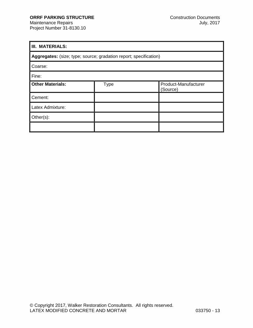
ORRF PARKING STRUCTURE Construction Documents Maintenance Repairs July, 2017 Project Number 31-8130.10
© Copyright 2017, Walker Restoration Consultants. All rights reserved. LATEX MODIFIED CONCRETE AND MORTAR 033750 - 13
III. MATERIALS:
Aggregates: (size; type; source; gradation report; specification)
Coarse:
Fine:
Other Materials: Type Product-Manufacturer (Source)
Cement:
Latex Admixture:
Other(s):
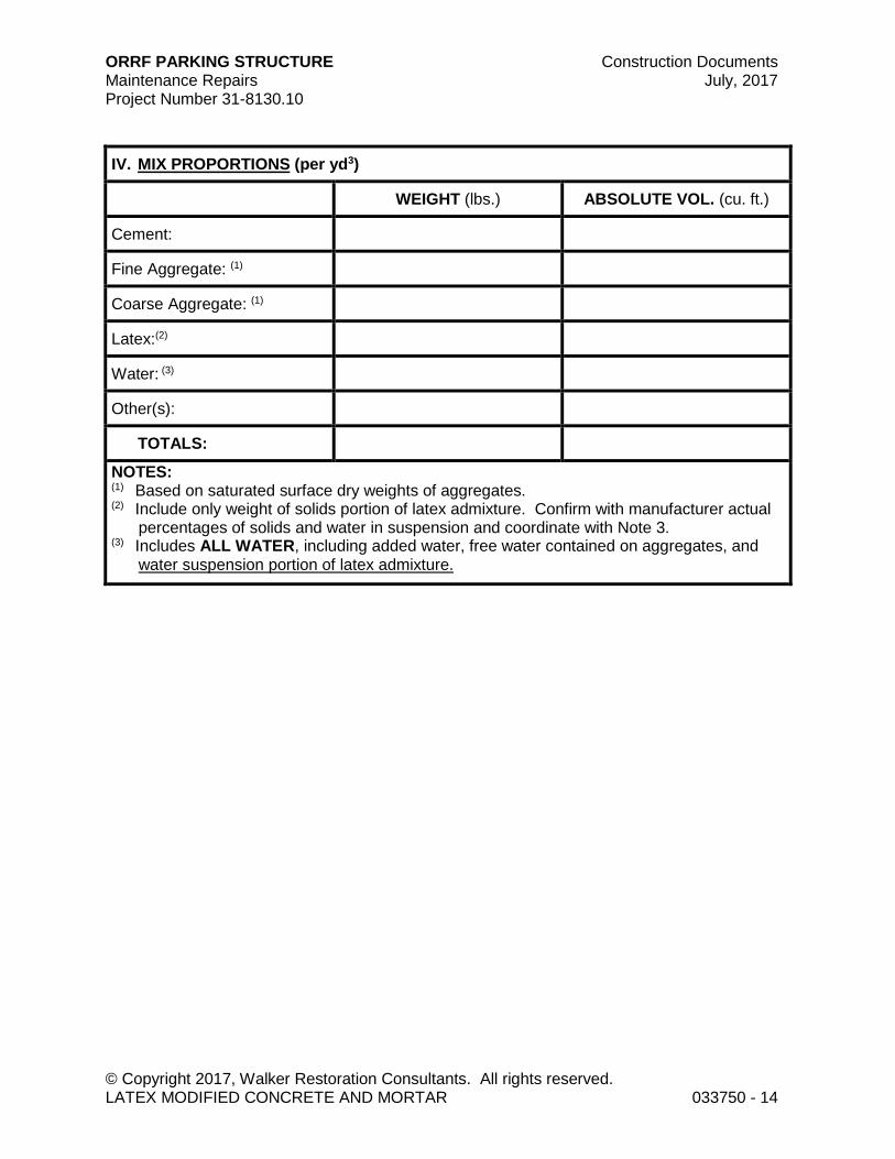
ORRF PARKING STRUCTURE Construction Documents Maintenance Repairs July, 2017 Project Number 31-8130.10
© Copyright 2017, Walker Restoration Consultants. All rights reserved. LATEX MODIFIED CONCRETE AND MORTAR 033750 - 14
IV. MIX PROPORTIONS (per yd3)
WEIGHT (lbs.) ABSOLUTE VOL. (cu. ft.)
Cement:
Fine Aggregate: (1)
Coarse Aggregate: (1)
Latex:(2)
Water: (3)
Other(s):
TOTALS:
NOTES: (1) Based on saturated surface dry weights of aggregates. (2) Include only weight of solids portion of latex admixture. Confirm with manufacturer actual
percentages of solids and water in suspension and coordinate with Note 3. (3) Includes ALL WATER, including added water, free water contained on aggregates, and
water suspension portion of latex admixture.

ORRF PARKING STRUCTURE Construction Documents Maintenance Repairs July, 2017 Project Number 31-8130.10
© Copyright 2017, Walker Restoration Consultants. All rights reserved. LATEX MODIFIED CONCRETE AND MORTAR 033750 - 15
V. RATIOS
Water (4) = Cement
lb. lb.
Fine Agg. = Total Agg
lb. lb.
VII. ADMIXTURES
Air Entraining Agent (A.E.A.): oz. per 100# cement
Water Reducer oz. per 100# cement
Latex Emulsion gal per sack cement
Other(s)
VI. SPECIFIC GRAVITIES
Fine Aggregate
Coarse Aggregate

ORRF PARKING STRUCTURE Construction Documents Maintenance Repairs July, 2017 Project Number 31-8130.10
© Copyright 2017, Walker Restoration Consultants. All rights reserved. LATEX MODIFIED CONCRETE AND MORTAR 033750 - 16
VIII. STANDARD DEVIATION ANALYSIS: Yes N/A
(Complete this section only if mix design was developed using standard deviation analysis of previous project test results. If other method was used, check "N/A".)
Number of Test Cylinders Evaluated: Standard Deviation:
Mix Designs Proportioned to Achieve f'cr = f'c + psi
NOTE: Mix designs shall be proportioned to achieve f'cr equal to or greater than the larger of f'cr = f'c + 1.34s [s= calculated standard deviation] or f'cr = f'c + 2.33s - 500 (Refer to ACI 301 for increased deviation factor when less than 30 tests are available.)

ORRF PARKING STRUCTURE Construction Documents Maintenance Repairs July, 2017 Project Number 31-8130.10
© Copyright 2017, Walker Restoration Consultants. All rights reserved. LATEX MODIFIED CONCRETE AND MORTAR 033750 - 17
IX. TRIAL MIXTURE TEST DATA: Yes N/A
(Complete this section only if mix design is based on data from trial test mixture(s) batched by testing agency or Contractor. If other method was used, check "N/A".)
Age (days)
Trial Mix #1 (comp. str.)
Trial Mix #2 (comp. str.)
Trial Mix #3 (comp. str.)
7
7
28
28
28 day average compressive strength: psi
DESIGN MIX CHARACTERISTICS
Slump = in. Air Content = %
Unit Wet Wt. = pcf Unit Dry Wt. = pcf
Mix Design Proportioned to Achieve: f'c + 1200 psi (1200 psi increases to 1400 psi when f'c > 5000 psi)
ACTUAL MIX CHARACTERISTICS
Initial Slump = in. Final Slump in.
Unit Wet Wt.= pcf. Unit Dry Wt. = pcf
Air Content = %
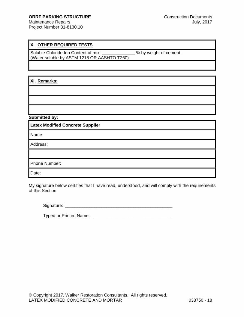
ORRF PARKING STRUCTURE Construction Documents Maintenance Repairs July, 2017 Project Number 31-8130.10
© Copyright 2017, Walker Restoration Consultants. All rights reserved. LATEX MODIFIED CONCRETE AND MORTAR 033750 - 18
X. OTHER REQUIRED TESTS
Soluble Chloride Ion Content of mix: % by weight of cement (Water soluble by ASTM 1218 OR AASHTO T260)
XI. Remarks:
Submitted by:
Latex Modified Concrete Supplier
Name:
Address:
Phone Number:
Date:
My signature below certifies that I have read, understood, and will comply with the requirements of this Section.
Signature: ____________________________________________ Typed or Printed Name: _________________________________

ORRF PARKING STRUCTURE Construction Documents Maintenance Repairs July, 2017 Project Number 31-8130.10
© Copyright 2017, Walker Restoration Consultants. All rights reserved. LATEX MODIFIED CONCRETE AND MORTAR 033750 - 19
REQUIRED ATTACHMENTS
Coarse aggregate grading report
Fine aggregate grading report
Concrete compressive strength data used for standard deviation calculations
Chloride ion data and related calculations
Admixture compatibility certification letter
INSTRUCTIONS:
1. Fill in all blank spaces. Use -0- (Zero) or N.A. (Not Applicable) where appropriate. See "Design and Control of Concrete Mixtures: 13th Edition by Portland Cement Association, for assistance in completing this form.
2. Provide the necessary documentation to support any laboratory test results or compliance to standard ASTM test methods or specifications referenced in the mix design submittal form.
3. If mix design utilizes multiple aggregate material sources, submit chloride ion content test data of each component from material suppliers. Test data shall be not more than 1 yr old.
Attach letter of certification that all admixtures, including latex admixture, are compatible for this mix design.
© Copyright 2017. All rights reserved. No part of this document may be reproduced in any form or by any means without permission from Walker Restoration Consultants.

ORRF PARKING STRUCTURE Construction Documents Maintenance Repairs July, 2017 Project Number 31-8130.10
© Copyright 2017, Walker Restoration Consultants. All rights reserved. TROWEL APPLIED MORTAR 033760 - 1
SECTION 033760 - TROWEL APPLIED MORTAR
PART 1 - GENERAL
1.1 RELATED DOCUMENTS
A. Drawings and general provisions of Contract, including General and Supplementary Conditions and Division 01 Specification Sections apply to this Section.
1.2 SUMMARY
A. This Section includes the provision of all labor, materials, supervision and incidentals necessary to prepare deteriorated or damaged concrete surfaces and install patches to overhead and vertical surfaces to restore original surface condition and integrity.
B. Related Sections: Following Sections contain requirements that relate to this Section:
1. Division 01 Section "Submittal Procedures." 2. Division 02 Section "Work Items." 3. Division 02 Section "General Concrete Surface Preparation."
Division 02 Section "Surface Preparation for Patching."
1.3 QUALITY ASSURANCE
A. Work shall conform to requirements of ACI 301 as applicable except where more stringent requirements are shown on Drawings or specified in this Section.
B. Testing Agency:
1. Independent testing laboratory employed by Contractor and acceptable to Engineer/Architect.
2. Accredited by AASHTO under ASTM C1077. Testing laboratory shall submit documented proof of ability to perform required tests.
C. Testing Agency is responsible for conducting, monitoring and reporting results of all tests required under this Section. Testing Agency has authority to reject mortar not meeting Specifications.
D. Sampling and testing of mortar shall be performed by ACI certified Concrete Field Technicians Grade I. Certification shall be no more than three years old.
E. Testing Agency shall submit following information for Field Testing of Concrete unless modified in writing by Engineer/Architect:
1. Project name and location. 2. Contractor's name.
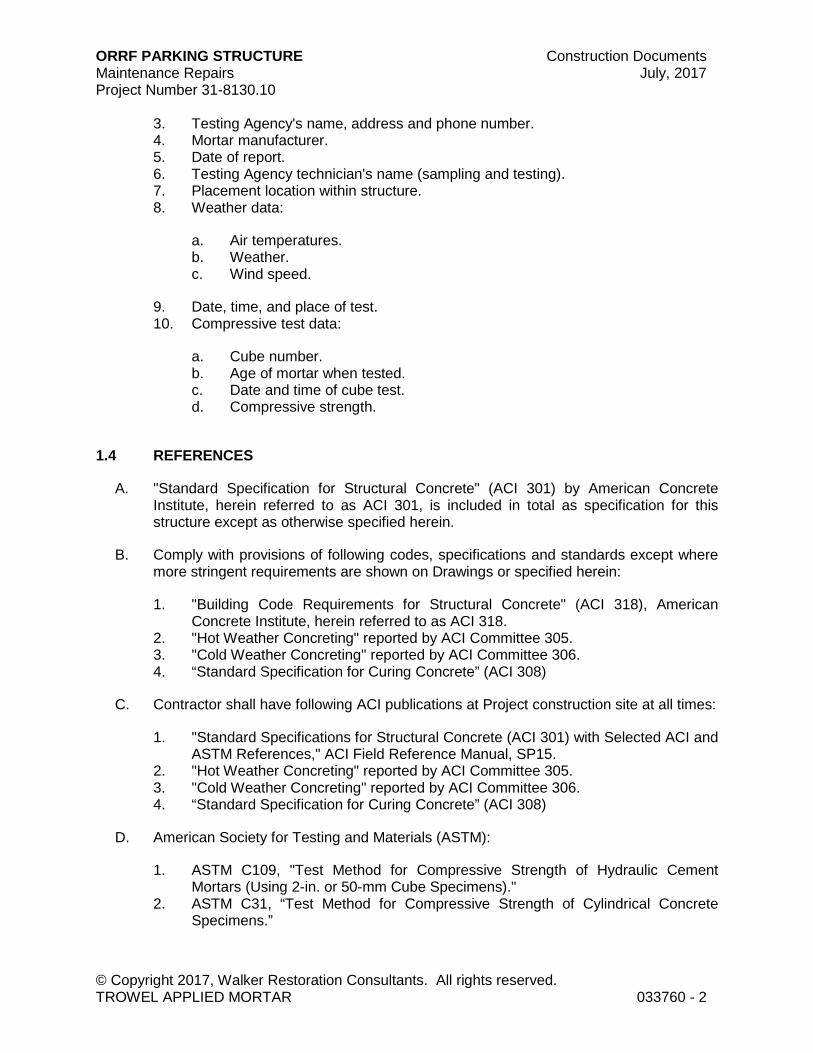
ORRF PARKING STRUCTURE Construction Documents Maintenance Repairs July, 2017 Project Number 31-8130.10
© Copyright 2017, Walker Restoration Consultants. All rights reserved. TROWEL APPLIED MORTAR 033760 - 2
3. Testing Agency's name, address and phone number. 4. Mortar manufacturer. 5. Date of report. 6. Testing Agency technician's name (sampling and testing). 7. Placement location within structure. 8. Weather data:
a. Air temperatures. b. Weather. c. Wind speed.
9. Date, time, and place of test. 10. Compressive test data:
a. Cube number. b. Age of mortar when tested. c. Date and time of cube test. d. Compressive strength.
1.4 REFERENCES
A. "Standard Specification for Structural Concrete" (ACI 301) by American Concrete Institute, herein referred to as ACI 301, is included in total as specification for this structure except as otherwise specified herein.
B. Comply with provisions of following codes, specifications and standards except where more stringent requirements are shown on Drawings or specified herein:
1. "Building Code Requirements for Structural Concrete" (ACI 318), American Concrete Institute, herein referred to as ACI 318.
2. "Hot Weather Concreting" reported by ACI Committee 305. 3. "Cold Weather Concreting" reported by ACI Committee 306. 4. “Standard Specification for Curing Concrete” (ACI 308)
C. Contractor shall have following ACI publications at Project construction site at all times:
1. "Standard Specifications for Structural Concrete (ACI 301) with Selected ACI and ASTM References," ACI Field Reference Manual, SP15.
2. "Hot Weather Concreting" reported by ACI Committee 305. 3. "Cold Weather Concreting" reported by ACI Committee 306. 4. “Standard Specification for Curing Concrete” (ACI 308)
D. American Society for Testing and Materials (ASTM):
1. ASTM C109, "Test Method for Compressive Strength of Hydraulic Cement Mortars (Using 2-in. or 50-mm Cube Specimens)."
2. ASTM C31, “Test Method for Compressive Strength of Cylindrical Concrete Specimens.”

ORRF PARKING STRUCTURE Construction Documents Maintenance Repairs July, 2017 Project Number 31-8130.10
© Copyright 2017, Walker Restoration Consultants. All rights reserved. TROWEL APPLIED MORTAR 033760 - 3
1.5 SUBMITTALS
A. Make submittals in accordance with requirements of Division 01 and as specified in this Section.
B. Contractor: At pre-construction meeting, submit procedures for demolition, surface preparation, material batching, placement, finishing, and curing of application. Provide procedure to protect fresh patches from severe weather conditions.
C. Testing Agency: Promptly report all mortar test results to Engineer/Architect and Contractor. Include following information:
1. See Article "Quality Assurance," paragraph "Testing Agency shall submit...." 2. Strength determined in accordance with ASTM C109.
D. See requirements of Division 01 Section, “Submittal Procedures,” Part 1 heading, “Submittal Procedures,” for limits to resubmittals.
E. See requirements of Division 01 Section, “Submittal Procedures,” Part 2 heading, “Requests for Information,” for RFI constraints.
PART 2 - PRODUCTS
2.1 MATERIALS
A. Trowel Applied Repair Mortar: Shall be prepackaged, polymer-modified cementitious repair mortar with integral corrosion inhibitor capable of vertical/overhead application by trowel achieving a minimum 3,000 psi compressive strength at 7 days and 5,000 psi compressive strength at 28 days per ASTM C 109 as certified by manufacturer.
1. Acceptable materials for this Work are as follows:
a. Acceptable materials for overhead and vertical work:
1) “MasterEmaco N400 RS,” by BASF Construction Chemicals, Shakopee, MN.
2) “Verticoat Supreme,” by The Euclid Chemical Company, Cleveland, OH.
3) “SikaRepair SHB with Latex R”, by Sika Corporation, Lyndhurst, NJ. 4) “PLANITOP X or XS by MAPEI Corporation, Deerfield Beach, FL
b. Acceptable materials for horizontal repair work:
1) “MasterEmaco T 310 CI,” by BASF Construction Chemicals, Shakopee, MN.
2) “Concrete Top Supreme,” by The Euclid Chemical Company, Cleveland, OH.
3) “Sikatop 122 Plus,” Sika Corporation, Lyndhurst, N.J.
ORRF PARKING STRUCTURE Construction Documents Maintenance Repairs July, 2017 Project Number 31-8130.10
© Copyright 2017, Walker Restoration Consultants. All rights reserved. TROWEL APPLIED MORTAR 033760 - 4
“Planitop 18” by MAPEI Corporation, Deerfield Beach, FL
2.2 MATERIAL ACCESSORIES
A. Extended Open Time Epoxy Bonding Agent: Three component, water based, epoxy modified portland cement bonding agent and corrosion inhibitor coating providing the recommended Manufacturer’s open time in which to apply repair mortar. Product shall be capable of achieving bond strength of 2,700 psi per ASTM C 882.
1. Acceptable materials for this Work are:
a. “Duralprep A.C.” by The Euclid Chemical Company, Cleveland, OH. b. “Sika Armatec 110 EpoCem”, by Sika Corporation, Lyndhurst, NJ. c. “PLANIBOND 3C”, by MAPEI Corporation, Deerfield Beach, FL.
B. Epoxy Adhesive: 2 or 3 component, 100 percent solids, 100 percent reactive compound suitable for use on dry or damp surfaces. Product shall be capable of achieving bond strength of 1,800 psi per ASTM C 882.
1. Acceptable materials for this Work are:
a. “MasterEmaco P 124” or “MasterEmaco ADH 326,” by BASF Construction Chemicals, Shakopee, MN.
b. “Euco #452 Epoxy Series,” or “Duralcrete Epoxy Series”, by The Euclid Chemical Company, Cleveland, OH.
c. Sikadur 32 Hi-Mod LPL”, by Sika Corporation, Lyndhurst, NJ. d. “Planibond EBA”, by MAPEI Corporation, Deefield Beach, FL.
PART 3 - EXECUTION
3.1 PREPARATION
A. Surface Preparation: Cavity surfaces shall be clean and dry prior to commencement of patch installation. Preparation of cavity to receive new mortar shall be in accordance with Section "Surface Preparation for Patching” and manufacturer's instructions.
3.2 INSTALLATION
A. Repair Mortar Bonding Grout:
1. Mix and apply bonding grout in strict accordance with manufacturer's recommendations.
2. If bonding grout dries, cavity shall not be patched until it has been recleaned and prepared as specified in Section "Surface Preparation for Patching." Grout shall not be applied to more cavities than can be patched within 0.25 hr by available manpower.

ORRF PARKING STRUCTURE Construction Documents Maintenance Repairs July, 2017 Project Number 31-8130.10
© Copyright 2017, Walker Restoration Consultants. All rights reserved. TROWEL APPLIED MORTAR 033760 - 5
B. Epoxy Bonding Agent Extended Open Time:
1. In strict accordance with manufacturer’s recommendations, mix and apply epoxy bonding agent to prior to placing forms in areas to receive form and place repair mortar.
C. Mortar Placement: Patching materials shall be placed immediately following grout application in strict accordance with manufacturer's instructions. Properly proportioned and mixed patch material shall be placed using trowels to consolidate patch so that no voids exist within new material and continuous contact with base concrete is achieved. Supplemental wire mesh shall be required for delamination and spall repairs greater than two inches in depth. Fresh bonding grout is required between successive lifts of patching material.
3.3 CURING
A. Protect freshly placed concrete repair mortar from premature drying and excessive cold or hot temperatures. Comply with ACI 306.1 for cold-weather protection and ACI 301 for hot-weather protection during placement. Keep patch material continually moist prior to final curing by evaporation retarder, misting, sprinkling, or using absorptive mat or fabric covering kept continually moist.
1. Evaporation Retarder: Apply evaporation retarder to unformed concrete surfaces if hot, dry, or windy conditions cause moisture loss approaching 0.1 lb/sq. ft. x h before and during finishing operations. Apply material according to manufacturer’s written instructions one or more times after placement, but prior to float finishing. Repeated applications are prohibited after float finishing has begun.
2. Acceptable evaporation retarder materials for this Work are:
a. “Cimfilm”, by Axim Concrete Technologies. b. “MasterKure ER 50”, by BASF Construction Chemicals, Shakopee, MN. c. “Aquafilm”, by Conspec Marketing & Manufacturing Co., Inc. d. “Sure-Film (J-74)’, by Dayton Superior Corporation. e. “Eucobar”, or “Tamms Surface Retarder”, by The Euclid Chemical
Company, Cleveland, OH. f. “E-Con”, by L&M Construction Chemicals, Inc. g. “EVRT”, by Russ Tech Admixtures, Inc. h. “SikaFilm”, by Sika Corporation, Lyndhurst, NJ.
B. Final Curing: Curing compounds complying with ASTM C309 may be used in accordance with recommendations of ACI 506.7, "Specification for Concrete." Provide additional curing immediately following initial curing and before patch material has dried. Use one of following materials or methods:
1. Continue method used in initial curing. 2. Material conforming to ASTM C171. 3. Curing compounds conforming to ASTM C309.

ORRF PARKING STRUCTURE Construction Documents Maintenance Repairs July, 2017 Project Number 31-8130.10
© Copyright 2017, Walker Restoration Consultants. All rights reserved. TROWEL APPLIED MORTAR 033760 - 6
4. Other moisture retaining covering as approved by Engineer/Architect. 5. Duration of Curing: Continue curing for first 7 days after patch placement. During
initial and final curing periods maintain patch material above 50° F. 6. Prevent rapid drying at end of curing period. 7. Provide additional curing as required or recommended by manufacturer.
C. Curing Compound (VOC Compliant, less than 350 g/l): Comply with ASTM C 309, Type 1, Class A or B. Moisture loss shall be not more than 0.55 kg/m2 when applied at 200 sq. ft/gal. Manufacturer’s certification is required. Silicate based compounds prohibited.
1. Subject to project requirements provide one of the following products:
a. “Kurez DR VOX” or “Kurez RC,” or “Kurez RC Off,” Euclid Chemical Company.
b. “RxCure WB,” or “RxCure VOC” or “W.B. Cure VOC,” Conspec Marketing & Manufacturing.
c. “MasterKure CC 200 WB” or “MasterKure CC 160 WB” BASF Construction Chemicals, LLC.
d. “MAPECURE DR”, by MAPEI Corporation, Deerfield Beach, FL.
2. Additional requirements:
a. With product submittal provide plan and procedures for removal of residual curing compound prior to application of sealers, coatings, stains, pavement markings and other finishes.
b. Provide a summary of testing to show adequate surface preparation for successful application of sealers, coatings, stains, pavement markings, and other finishes.
3.4 FIELD QUALITY CONTROL BY TESTING AGENCY
A. Concrete Compressive Strength:
1. Mold test cubes in the field in accordance ASTM C-31 and ASTM C-109 as follows and further below:
a. Take a minimum of twelve (12) cubes for each 10 cu ft, or fraction thereof, of each repair mortar placed in any one day
b. Use 2 in. x 2 in. cubes. c. Additional 2 cubes shall be taken and field cured under conditions of cold
weather concreting, and when directed by Engineer/Architect. d. Cover specimens properly, immediately after finishing. Protect molds from
contact with sources of water for first 24 hours after molding.
2. Fabricate and cure test cubes per ASTM C-109, except as follows:
a. Do not remove specimens from molds before 24 hours. b. To verify 7 and 28-day compressive strengths:
ORRF PARKING STRUCTURE Construction Documents Maintenance Repairs July, 2017 Project Number 31-8130.10
© Copyright 2017, Walker Restoration Consultants. All rights reserved. TROWEL APPLIED MORTAR 033760 - 7
1) During first 24 hours after molding, store test specimens under conditions that maintain temperature immediately adjacent to specimens in range of 60 to 80° F. and prevent loss of moisture from specimens.
2) Remove test specimens from molds at end of 24 hours and air dry in laboratory until moment of test.
c. To verify compressive strength of test cubes required due to cold weather concreting conditions:
1) Store test specimens on structure as near to point of sampling as possible and protect from elements in same manner as that given to portion of structure as specimen represents.
2) Transport to test laboratory no more than 4 hours before testing. Remove molds from specimens immediately before testing.
3. Compression Test:
a. Test 3 cubes at 1 day. Test 3 cubes at 7 days.
b. Test 3 cubes at 28 days. c. Hold 3 cubes in reserve for use as Engineer/Architect directs.
4. Unless notified by Engineer/Architect, reserve cubes may be discarded without being tested after 56 days.
3.5 EVALUATION AND ACCEPTANCE OF TROWEL APPLIED MORTAR REPAIRS
A. Acceptance of Repairs (ACI 301):
1. Acceptance of completed concrete Work will be according to provisions of ACI 301.
2. Patched areas shall be sounded by Engineer/Architect and Contractor with hammer or rod after curing for 72 hours. Contractor shall repair all hollowness detected by removing and replacing patch or affected area at no extra cost to Owner.
3. If shrinkage cracks appear in patch area when initial curing period is completed, patch shall be considered defective, and it shall be removed and replaced by Contractor at no extra cost.
END OF SECTION 033760
© Copyright 2017. All rights reserved. No part of this document may be reproduced in any form or by any means without permission from Walker Restoration Consultants.

ORRF PARKING STRUCTURE Construction Documents Maintenance Repairs July, 2017 Project Number 31-8130.10
© Copyright 2017, Walker Restoration Consultants. All rights reserved. CHEMICAL GROUT INJECTION SYSTEMS 033981 - 1
SECTION 033981 – CHEMICAL GROUT INJECTION SYSTEMS
PART 1 GENERAL
1.1 RELATED DOCUMENTS
A. Drawings and general provisions of Contract, including General and Supplementary Conditions and Division 1 Specification Sections apply to this Section.
1.2 SUMMARY
A. This Section includes the provision of all labor, materials, equipment, supervision and incidentals necessary to prepare cracks in structural concrete members and inject them with a chemical grout resin system.
1.3 QUALITY ASSURANCE
A. Testing Agency will be independent testing laboratory employed by Owner and approved by Engineer.
B. Testing Agency is responsible for conducting, monitoring and reporting to Owner results of all field tests of chemical grout resin injection and installation required under this Section with copy of all reports to Engineer and Contractor.
C. Submit following information for Field Testing of Chemical Grout Injection Installation unless modified in writing by Engineer:
1. Project name and location. 2. Contractor's name. 3. Testing Agency's name, address and phone number. 4. Chemical grout material supplier. 5. Date of report. 6. Testing Agency technician's name (sampling and testing). 7. Placement location within structure. 8. Chemical grout material data:
a. Resin type. b. Port type. c. Width of cracks injected (if applicable). d. Crack conditions (dry or wet). e. Injection port spacing. f. Initial and (if different) constant injection pressures. g. Use rate of chemical grout. h. Crack and port sealing patching material and application methods.
ORRF PARKING STRUCTURE Construction Documents Maintenance Repairs July, 2017 Project Number 31-8130.10
© Copyright 2017, Walker Restoration Consultants. All rights reserved. CHEMICAL GROUT INJECTION SYSTEMS 033981 - 2
9. Weather data:
a. Air temperatures. b. Weather. c. Wind speed.
10. Field test data:
a. Date, time and place of test. b. Thickness of resin in crack or void.
1.4 REFERENCES
A. "Standard Specifications for Structural Concrete," (ACI 301) by American Concrete Institute, herein referred to as ACI 301, is included in total as specification for this structure except as otherwise specified herein.
B. Comply with provisions of following codes, specifications and standards except where more stringent requirements are shown on Drawings or specified herein:
1. "Building Code Requirements for Reinforced Concrete," (ACI 318), American Concrete Institute, herein referred to as ACI 318.
2. "Causes, Evaluation, and Repair of Cracks in Concrete Structures" (ACI 224.112), American Concrete Institute.
3. "State-of-the-Art Report on Parking Structures" (ACI 326), American Concrete Institute.
1.5 SUBMITTALS
A. Make submittals in accordance with requirements of Division 1 and as specified in this Section.
B. Contractor: Submit manufacturer's product data sheets, technical sheets, recommended application procedures and information on chemical grout injection equipment.
C. Testing Agency: Promptly report all test results to Engineer and Contractor. Include following information:
1. See Article "Quality Assurance," paragraph "Submit following information for Field Testing...."
2. Visual examination of grout resin penetration.
1.6 WARRANTY
A. System manufacturer and Contractor shall furnish Owner written single source performance guarantee that chemical grout injection system will be free of defects

ORRF PARKING STRUCTURE Construction Documents Maintenance Repairs July, 2017 Project Number 31-8130.10
© Copyright 2017, Walker Restoration Consultants. All rights reserved. CHEMICAL GROUT INJECTION SYSTEMS 033981 - 3
related to design, workmanship or material deficiency for 3-year period from date of acceptance of Work required under this Section against leakage or bond failure of patching materials.
B. Any repair under this guarantee shall be done at no cost to Owner. Guarantee shall be provided by Contractor and manufacturer of system.
PART 2 - PRODUCTS
2.1 MATERIALS AND EQUIPMENT
A. Hydrophobic Chemical grout injection system shall be one of following:
1. "Mountain Grout” as manufactured by Green Mountain International, Inc., 235 Pigeon Street, Waynesville, NC 28786.
2. "Hydro Active Cut” as manufactured by De Neef Construction Chemicals (U.S.) Inc., P.O. Box 1219, Waller, Texas 77484.
B. Equipment:
1. Equipment used to inject grout shall be capable of following:
a. High pressure range of 2000 to 2500 psi by positive displacement. b. Injection of grout system at constant pressures as required by the
manufacturer.
PART 3 - EXECUTION
3.1 PREPARATION
A. Crack Identification:
1. All cracks 1/32 in. wide or greater that are designated by Engineer, and not coincident with principal delamination, shall be injected. Cracks that occur coincident with principal delaminations shall not be injected, unless authorized by Engineer.
2. All cracks shall be located by Contractor at time of construction and marked with chalk. Cracks to be injected are to be verified and approved by the Engineer prior to crack preparation.
B. Crack Preparation for Injection:
1. Surface of concrete adjacent to crack must be free of all laitance, efflorescence, dirt or foreign particles.
2. Cracks are to be prepared according to Drawings and Work Item Details. 3. Cracks may be damp or dry as per injection material manufacturer's

ORRF PARKING STRUCTURE Construction Documents Maintenance Repairs July, 2017 Project Number 31-8130.10
© Copyright 2017, Walker Restoration Consultants. All rights reserved. CHEMICAL GROUT INJECTION SYSTEMS 033981 - 4
recommended installation procedures. 4. Drill hole at 45 degree angle, beginning at a distance away from the crack so
that the drilled hole intercepts the crack at approximately one half the thickness of the concrete. If repairing a vertical concrete face, drill the first hole at the bottom of the crack and work upwards.
5. Stagger holes either side of crack with a 12” maximum spacing. 6. Insert grout port into the drilled hole and tighten according to manufactures
recommendations. 7. Flush crack with water prior to grouting.
3.2 INSTALLATION
A. Chemical Grout Injection:
1. Flush crack will indicate how the crack will behave during the grout injection and prime the crack for the chemical reaction to occur.
2. Begin the injection on the lowest port on a vertical crack. Inject material until it appears at the next adjacent port. Disconnect and start injection on the next port. Continue to inject up the crack moving from port to port. After injection of a few ports, come back to the first port and reinject all the ports for a second time. Continue the procedure until the crack is completely filled and no water is leaking from crack.
3. After determining the crack is not leaking, clean the crack surface flush; remove the ports after the resin is set and patch injection holes according to repair Details.
4. Contractor shall adhere to all limitations and cautions for chemical grout injection material as per manufacturer's current printed literature.
5. For injecting ceiling cracks, follow manufacture installation guidelines and recommendations.
6. Contractor shall adhere to all Federal, State and Local regulations for the use and disposal of all products.
B. Cleaning:
1. Contractor shall leave work area in clean condition when injection work is completed. Any chemical grout resin materials shall be cleaned off adjacent areas. Any painted surfaces are to be returned to original condition.
3.3 FIELD QUALITY CONTROL BY TESTING AGENCY
A. Evaluation and Acceptance of Chemical Grout Injection:
1. Results by visual examination will be reviewed by Engineer for lack of leaking water.
2. If the leakage continues in part of the crack, it shall be re-injected with no additional quantity as a pay item.
3. Port holes shall be filled with non-shrink grout material. Grout shall be applied with hard trowel, and be thoroughly rodded and tamped in place. Finish, texture
ORRF PARKING STRUCTURE Construction Documents Maintenance Repairs July, 2017 Project Number 31-8130.10
© Copyright 2017, Walker Restoration Consultants. All rights reserved. CHEMICAL GROUT INJECTION SYSTEMS 033981 - 5
and color to match existing surface.
END OF SECTION 033981
© Copyright 2017. All rights reserved. No part of this document may be reproduced in any form or by any means without permission from Walker Restoration Consultants.

ORRF PARKING STRUCTURE Construction Documents Maintenance Repairs July, 2017 Project Number 31-8130.10
© Copyright 2017, Walker Restoration Consultants. All rights reserved. EPOXY INJECTION SYSTEMS 036300 - 1
SECTION 036300 - EPOXY INJECTION SYSTEMS
PART 1 - GENERAL
1.1 RELATED DOCUMENTS
A. Drawings and general provisions of Contract, including General and Supplementary Conditions and Division 01 Specification Sections apply to this Section.
1.2 SUMMARY
A. This Section includes the provision of all labor, materials, equipment, supervision and incidentals necessary to prepare cracks in structural concrete members and inject them with a 2-component, moisture-insensiteve, 100 percent solids, low-viscosity epoxy resin system.
B. Related Sections: Following Sections contain requirements that relate to this Section:
1. Division 02 Section "Work Items." 2. Division 02 Section "General Concrete Surface Preparation." 3. Division 02 Section "Surface Preparation for Patching."
1.3 QUALITY ASSURANCE
A. Testing Agency will be independent testing laboratory employed by Owner and approved by Engineer/Architect.
B. Submit following information for Field Testing of Epoxy Injection Installation unless modified in writing by Engineer/Architect:
1. Project name and location. 2. Contractor's name. 3. Testing Agency's name, address and phone number. 4. Epoxy material supplier. 5. Date of report. 6. Testing Agency technician's name (sampling and testing). 7. Placement location within structure. 8. Epoxy material data:
a. Epoxy type. b. Gel type. c. Width of cracks injected (if applicable). d. Crack conditions (dry or wet). e. Injection port spacing. f. Initial and (if different) constant injection pressures.

ORRF PARKING STRUCTURE Construction Documents Maintenance Repairs July, 2017 Project Number 31-8130.10
© Copyright 2017, Walker Restoration Consultants. All rights reserved. EPOXY INJECTION SYSTEMS 036300 - 2
g. Use rate of epoxy.
9. Weather data:
a. Air temperatures. b. Weather. c. Wind speed.
10. Field test data:
a. Date, time and place of test. b. Thickness of epoxy in crack or void.
1.4 REFERENCES
A. "Standard Specifications for Structural Concrete," (ACI 301) by American Concrete Institute, herein referred to as ACI 301, is included in total as specification for this structure except as otherwise specified herein.
B. Comply with provisions of following codes, specifications and standards except where more stringent requirements are shown on Drawings or specified herein:
1. "Building Code Requirements for Reinforced Concrete," (ACI 318), American Concrete Institute, herein referred to as ACI 318.
2. "Causes, Evaluation, and Repair of Cracks in Concrete Structures" (ACI 224.112), American Concrete Institute.
3. "State-of-the-Art Report on Parking Structures" (ACI 362), American Concrete Institute.
4. ”Specification for Crack Repair by Epoxy Injection” (ACI 503.7), American Concrete Institute.
5. “Guide for the Application of Epoxy and Latex Adhesives for Bonding Freshly Mixed and Hardened Concretes”, (ACI 503.6), American Concrete Institute.
6. "Standard Specification for Bonding Hardened Concrete, Steel, Wood, Brick, and Other Materials to Hardened Concrete with a Multi-Component Epoxy Adhesive" (ACI 503.1), American Concrete Institute.
7. "Guide for Repair of Concrete Bridge Superstructures" Reported by ACI Committee 546 (ACI 546.1).
C. Contractor shall have following ACI/ICRI publications at Project construction site at all times:
1. ”Specification for Crack Repair by Epoxy Injection” (ACI 503.7), American Concrete Institute.” Structural Crack Repair by Epoxy Injection”, ACI RAP Bulletin 1, American Concrete Institute.
2. "Standard Specification for Bonding Hardened Concrete, Steel, Wood, Brick, and Other Materials to Hardened Concrete with a Multi-Component Epoxy Adhesive" (ACI 503.1), American Concrete Institute.
ORRF PARKING STRUCTURE Construction Documents Maintenance Repairs July, 2017 Project Number 31-8130.10
© Copyright 2017, Walker Restoration Consultants. All rights reserved. EPOXY INJECTION SYSTEMS 036300 - 3
1.5 SUBMITTALS
A. Make submittals in accordance with requirements of Division 01 and as specified in this Section.
B. Contractor: Submit manufacturer's product data sheets, technical sheets, recommended application procedures and information on epoxy injection equipment.
C. Testing Agency: Promptly report all test results to Engineer/Architect and Contractor. Include following information:
1. See Article "Quality Assurance," paragraph "Submit following information for Field Testing...."
2. Visual examination of epoxy resin penetration.
1.6 WARRANTY
A. System manufacturer and Contractor shall furnish Owner written single source performance guarantee that epoxy resin injection system will be free of defects related to design, workmanship or material deficiency for 3-year period from date of acceptance of Work required under this Section against leakage or bond failure:
1. Any adhesive or cohesive failure. 2. Crazing or other weathering deficiency. 3. Normal abrasion or tear failure.
B. Any repair under this guarantee shall be done at no cost to Owner. Guarantee shall be provided by Contractor and manufacturer of system.
PART 2 - PRODUCTS
2.1 MATERIALS AND EQUIPMENT
A. Injection epoxy shall be one of following:
1. "MasterInject 1380" or “MasterInject 1500” as manufactured by BASF Construction Chemicals., Shakopee, MN.
2. "Sikadur 35 Hi-Mod LV" or “Sikadur 52” as manufactured by Sika Chemical
Corporation, Lyndhurst, NJ. 3. "Epoxy HP-LV" as manufactured by Hunt Process Corp-Southern, Ridgeland,
MS. 4. “Pro-Poxy 50 Super LV” as manufactured by Unitex, Kansas City, MO. 5. “Eucopoxy” or “Duralcrete LV” as manufactured by The Euclid Chemical
Company, Cleveland OH. 6. “Sure Inject J56 SLV” as manufactured by Dayton Superior Corp., Miamisburg
OH. 7. “KonTek 11 LV” as manufactured by Contech Group, Inc. Seattle, WA.

ORRF PARKING STRUCTURE Construction Documents Maintenance Repairs July, 2017 Project Number 31-8130.10
© Copyright 2017, Walker Restoration Consultants. All rights reserved. EPOXY INJECTION SYSTEMS 036300 - 4
8. “Kemko 038” as manufactured by ChemCo Systems, Inc., Redwood City, CA.
B. Epoxy gel shall be as specified by the selected injection epoxy manufacturer.
C. Equipment:
1. Epoxy injection unit shall be portable and equipped with positive displacement-type pumps with interlock to provide positive ration control of epoxy injection resin components. Pumps shall be air or electric powered and shall provide in-line mixing and metering system and shall be equipped with drain-back plugs.
2. Equipment used to inject epoxy shall be capable of following:
a. Automatic proportioning of materials within mix ratio tolerances set by epoxy resin manufacturer.
b. Delivery of components, resin and hardeners, from separate reservoirs to mixing type discharge head.
c. Complete and uniform mixing of components at discharge head. d. Injection of resin system at constant pressures not to exceed 150 psi.
PART 3 - EXECUTION
3.1 PREPARATION
A. Crack Identification:
1. All cracks 0.03 in. wide or greater that are designated by Engineer/Architect, and not coincident with principal delamination, shall be injected. Cracks that occur coincident with principal delaminations shall not be injected.
2. Cracks requiring repair shall be located by Contractor at time of construction and marked with chalk.
B. Crack Preparation for Injection:
1. Surface of concrete adjacent to crack must be free of all laitance, efflorescence, dirt or foreign particles.
2. Cracks may be damp or dry as per injection material manufacturer's recommended installation procedures.
3. All cracks shall be properly sealed along their exposed length with an approved epoxy gel.
4. Epoxy injection ports shall be uniformly spaced along crack and shall be installed as recommended by system manufacturer. If concrete member being injected is exposed on both sides, provide injection ports on opposite sides at staggered intervals.
5. Apply epoxy gel around injection port to provide an adequate seal to prevent escape of injection resin from perimeter of port while under pressure.
6. Apply epoxy gel for sealing in manner that will result in minimal defacing or disorganization of concrete substrate.
ORRF PARKING STRUCTURE Construction Documents Maintenance Repairs July, 2017 Project Number 31-8130.10
© Copyright 2017, Walker Restoration Consultants. All rights reserved. EPOXY INJECTION SYSTEMS 036300 - 5
3.2 INSTALLATION
A. Epoxy Injection:
1. Dispense epoxy injection resin under constant pressure in accordance with manufacturer's recommended procedures or as required to achieve maximum filling and penetration of crack without inclusion of air voids in epoxy resin material.
2. Injection shall begin at lowest port and progress incrementally higher. 3. Appearance of epoxy resin at next higher port shall be considered evidence of
successful crack filling. 4. If penetration of epoxy resin into cracks is not possible, notify Engineer/Architect
prior to discontinuing injection procedures. If alternate injection procedures are possible, submit procedure in writing to Engineer/Architect for review.
5. Contractor shall adhere to all limitations and cautions for epoxy resin injection material as per manufacturer's current printed literature.
B. Cleaning:
1. When cracks are completely filled, allow adhesive to cure for sufficient time to allow the removal of the surface seal without any draining or runback of epoxy material from the cracks.
2. Remove the surface seal material, ports, and injection adhesive runs or spills from concrete surfaces.
3. Finish the face of the crack flush to the adjacent concrete, removing any indentations or protrusions caused by the placement of entry ports.
4. Match work area to adjacent surface including any surface treatments.
END OF SECTION 036300
©Copyright 2017. All rights reserved. No part of this document may be reproduced in any form or by any means without permission from Walker Restoration Consultants.
ORRF PARKING STRUCTURE Construction Documents Maintenance Repairs July, 2017 Project Number 31-8130.10
© Copyright 2017, Walker Restoration Consultants. All rights reserved. TRAFFIC COATINGS 071800 - 1
SECTION 071800 – TRAFFIC COATINGS
PART 1 - GENERAL
1.1 RELATED DOCUMENTS
A. Drawings and general provisions of Contract, including General and Supplementary Conditions and Division 01 Specification Sections apply to this Section.
1.2 SUMMARY
A. A single installer shall be responsible for providing complete water proofing system including all products specified in following Sections:
1. Division 07 Section, “Traffic Coatings” 2. Division 07 Section, “Water Repellents” 3. Division 07 Section, “Concrete Joint Sealants” 4. Division 07 Section, “Expansion Joint Assemblies”
B. This Section includes traffic coating: Fluid applied, waterproofing, traffic-bearing elastomeric membrane with integral wearing surface.
C. Materials shall be compatible with materials or related Work with which they come into contact, and with materials covered by this Section.
D. Related Sections: Following Sections contain requirements that relate to this Section.
1. Division 07 Section, “Water Repellents” 2. Division 07 Section, “Concrete Joint Sealants” 3. Division 07 Section, “Expansion Joint Assemblies” 4. Division 09 Section, "Pavement Markings"
1.3 ADMINISTRATIVE REQUIREMENTS
A. Coordination:
1. Distribute reviewed submittals to all others whose Work is related.
B. Pre-installation Conference: Meet at project site well in advance of time scheduled for Work to proceed to review requirements for Work and conditions that could interfere with successful coating performance. Require every party concerned with coating Work, or required to coordinate with it or protect it thereafter, to attend. Include manufacturer's technical representative and warranty officer.
C. Make submittals in accordance with requirements of Division 01 Section, “Submittal Procedures:”
ORRF PARKING STRUCTURE Construction Documents Maintenance Repairs July, 2017 Project Number 31-8130.10
© Copyright 2017, Walker Restoration Consultants. All rights reserved. TRAFFIC COATINGS 071800 - 2
1. See requirements of Division 01 Section, “Submittal Procedures,” Part 1 heading, “Submittal Procedures,” for limits to resubmittals.
2. See requirements of Division 01 Section, “Submittal Procedures,” Part 2 heading, “Requests for Information,” for RFI constraints.
D. Submittals and Resubmittals: Engineer will review each of Contractor’s shop drawings and/or submittal data initial time and, should resubmittal be required, one additional time to verify that reasons for resubmittal have been addressed by Contractor and corrections made. Resubmittal changes/revisions/corrections shall be circled. Engineer will review only circled items and will not be responsible for non-circled changes/revisions/corrections and additions. Should additional resubmittals be required, Contractor shall reimburse Owner for all costs incurred, including cost of Engineer’s services made necessary to review such additional resubmittals. Owner shall in turn reimburse Engineer.
1.4 CLOSEOUT SUBMITTALS
A. Three copies of System Maintenance Manual.
B. Five copies of snow removal guidelines for areas covered by Warranty.
C. Final executed Warranty.
1.5 QUALITY ASSURANCE
A. Manufacturer’s Qualifications: Owner retains right to reject any manufacturer.
1. Evidence of acceptable previous work on WALKER-designed projects. If none, so state.
2. Evidence of financial stability acceptable to Engineer/Architect. 3. Listing of 20 or more projects completed with submitted system, to include:
a. Name and location of project. b. Type of system applied. c. On-Site contact with phone number.
B. Manufacturer's technical representative, acceptable to Engineer/Architect, shall be on site during surface preparation and initial stages of installation.
C. Installer’s Qualifications: Owner retains right to reject any manufacturer.
1. Evidence of compliance with Summary article paragraph "A single installer. . ." 2. Evidence that installer has successfully performed or has qualified staff who have
successfully performed at least 5 verifiable years of installations similar to those involved in this Contract, and minimum 10 projects with submitted system.
3. Listing of 5 or more installations in climate and size similar to this Project performed by installer’s superintendent.
ORRF PARKING STRUCTURE Construction Documents Maintenance Repairs July, 2017 Project Number 31-8130.10
© Copyright 2017, Walker Restoration Consultants. All rights reserved. TRAFFIC COATINGS 071800 - 3
D. Testing Agency: Independent testing laboratory employed by Contractor and acceptable to Engineer/Architect.
E. Certifications
1. Traffic coating shall satisfy current National Volatile Organic Compound (VOC) Emission Standards for Architectural Coatings.
2. Licensing/certification document from manufacturer that confirms system installer is a licensed/certified applicator for the manufacturer and is legally licensed to perform work in the state this project is being constructed.
3. Licensing/certification agreement shall include following information:
a. Applicator’s financial responsibility for warranty burden under agreement terms.
b. Manufacturer’s financial responsibility for warranty burden under agreement terms.
c. Process for dispute settlement between manufacturer and applicator in case of system failures where cause is not evident or cannot be assigned.
d. Authorized signatures for both Applicator Company and Manufacturer. e. Commencement date of agreement and expiration date (if applicable).
1.6 DELIVERY, STORAGE, AND HANDLING
A. Deliver all materials to site in original, unopened containers, bearing following information:
1. Name of product. 2. Name of manufacturer. 3. Date of preparation. 4. Lot or batch number.
B. Store materials under cover and protect from weather. Replace packages or materials showing any signs of damage with new material at no additional cost to Owner.
1.7 FIELD CONDITIONS
A. Weather and Substrate Conditions: Proceed with work only when existing and forecast weather and temperature of concrete substrate will permit work in accordance with manufacturer's recommendations.
1.8 WARRANTY
A. System Manufacturer: Furnish Owner with written total responsibility Joint and Several Warranty, detailing responsibilities of manufacturer and applicator with regard to warranty requirements (Joint and Several). Warranty shall provide that system will be free of defects, water penetration and chemical damage related to system design, workmanship or material deficiency, consisting of:

ORRF PARKING STRUCTURE Construction Documents Maintenance Repairs July, 2017 Project Number 31-8130.10
© Copyright 2017, Walker Restoration Consultants. All rights reserved. TRAFFIC COATINGS 071800 - 4
1. Any adhesive or cohesive failures. 2. Spalling surfaces. 3. Weathering. 4. Surface crazing (does not apply to traffic coating protection course). 5. Abrasion or tear failure resulting from normal traffic use. 6. Failure to bridge cracks less than 0.0625 in. or cracks existing at time of traffic
coating installation on double tees only.
B. If material surface shows any of defects listed above, supply labor and material to repair all defective areas and to repaint all damaged line stripes.
C. Warranty period shall be a 5 Year Joint and Several Warranty commencing with date of acceptance of work.
D. Perform any repair under this warranty at no cost to Owner.
E. Address following in terms of Warranty: length of warranty, change in value of warranty – if any- based on length of remaining warranty period, transferability of warranty, responsibilities of each party, notification procedures, dispute resolution procedures, and limitations of liability for direct and consequential damages.
F. Snowplows, vandalism, and abnormally abrasive maintenance equipment are not normal traffic use and are exempted from warranty.
PART 2 - PRODUCTS
A. Manufacturer: Subject to compliance with requirements, provide products of 1 of following, only where specifically named in product category:
1. Advanced Polymer Technology (APT), Harmony, PA 2. Master Builders Solutions, Shakopee, MN 3. Neogard Division of Jones-Blair Company (Neogard), Dallas, TX. 4. Lymtal International Inc. (Lymtal), Lake Orion, MI. 5. Tremco (Tremco), Cleveland, OH.
2.2 MATERIALS, TRAFFIC COATING
A. Acceptable low odor coatings are listed below. Coatings shall be compatible with all other materials in this Section and related work.
1. Heavy Duty – Low Odor, High Solids (100%):
a. AutoGard FC HD-48, Neogard. b. Iso-Flex 760 U HL AR and 760 U HL AL, Lymtal. c. MasterSeal Traffic 2500, Master Builders Solutions. d. Qualideck Heavy Vehicular HD-80 (152/252/372/512), APT e. Vulkem 360NF/950NF and 951NF, Tremco.

ORRF PARKING STRUCTURE Construction Documents Maintenance Repairs July, 2017 Project Number 31-8130.10
© Copyright 2017, Walker Restoration Consultants. All rights reserved. TRAFFIC COATINGS 071800 - 5
B. Provide ultraviolet screening for all traffic coating placed on this project.
C. Finish top coat shall be colored grey.
D. Substitutions: None for this project. Contact Engineer/Architect for consideration for future projects.
2.3 MATERIALS, CRACK SEALER
A. Repair for isolated random horizontal cracks 0.01 in. to 0.06 in. wide. Acceptable products:
1. Denedeck Crack Sealer, De Neef. 2. Iso-Flex 609 Epoxy Crack Sealer, Lymtal. 3. MasterSeal 630, BASF. 4. Sikadur 55 SLV Epoxy Crack Healer/Sealer, Sika. 5. SikaPronto 19TF, Sika.
PART 3 - EXECUTION
3.1 EXAMINATION
A. Examine surfaces to receive Work and report immediately in writing to Engineer/Architect any deficiencies in surface which render it unsuitable for proper execution of Work.
B. Coordinate and verify that related Work meets following requirements before beginning surface preparation and application:
1. Concrete surfaces are finished as acceptable for system to be installed. Correct all high points, ridges, and other defects in a manner acceptable to Engineer/Architect.
2. Curing compounds used on concrete surfaces are compatible with system to be installed.
3. Concrete surfaces have completed proper curing period for system selected. 4. Joint Sealants are compatible with traffic coatings.
3.2 PREPARATION
A. Seal all openings to occupied space to prevent cleaning materials, solvents and fumes from infiltration. All protective measures and/or ventilating systems required to prevent infiltration are incidental to this Work.
B. Acid etching is prohibited.
ORRF PARKING STRUCTURE Construction Documents Maintenance Repairs July, 2017 Project Number 31-8130.10
© Copyright 2017, Walker Restoration Consultants. All rights reserved. TRAFFIC COATINGS 071800 - 6
C. Remove all debonded traffic coatings. Remove all laitance and surface contaminants, including oil, grease and dirt, by shotblasting and appropriate degreasers, or as specified by manufacturer’s written recommendations to provide warranty.
D. Before applying materials, apply system to small area to assure that it will adhere to substrate and joint sealants and dry properly and to evaluate appearance.
E. All random cracks on concrete surface less than 0.03 in. wide and showing no evidence of water and/or salt water staining on ceiling below shall receive detail coat unless more complete treatment required in accordance with manufacturer's recommendations. Rout and seal random cracks, construction joints and control joints prior to installation of primer or base coat. Crack preparation including installation of joint sealant material, where required, is incidental to traffic coating work.
F. Mask off adjoining surfaces not to receive traffic coating and mask off drains to prevent spillage and migration of liquid materials outside membrane area. Provide neat/straight lines at termination of traffic coating.
3.3 INSTALLATION/APPLICATION
A. Installation should include all of the following steps:
1. Surface Preparation: Prepare concrete for system application. 2. Crack/Construction/Control/Cove Joint Sealing: Detail for crack bridging. 3. Primer Coat: Insure proper adhesion of membrane to substrate. 4. Base Coat: Provide crack spanning in conjunction with Crack Detail noted above. 5. Aggregate Coat – to hold aggregate in system, providing skid and wear close up
resistance. 6. Aggregate: Correct size, shape, hardness and amount necessary to insure
proper skid and wear resistance. 7. Top Coat: Lock aggregate into place, provide a maintainable surface and provide
resistance to ponding water, UV degradation, color loss and chemical intrusion.
B. Do all Work in accordance with manufacturer's written instructions and specifications including, but not limited to, moisture content of substrate, atmospheric conditions (including relative humidity and temperature), coverages, mil thicknesses and texture, and as shown on Drawings.
C. A primer coat is required for all systems. No exception.
D. Do not apply traffic coating material until concrete has been air dried at temperatures at or above 40ºF for at least 30 days after curing period specified.
E. Cease material installation under adverse weather conditions, or when temperatures are outside manufacturer's recommended limitations for installation, or when temperature of work area or substrate are below 40ºF.

ORRF PARKING STRUCTURE Construction Documents Maintenance Repairs July, 2017 Project Number 31-8130.10
© Copyright 2017, Walker Restoration Consultants. All rights reserved. TRAFFIC COATINGS 071800 - 7
F. All adjacent vertical surfaces shall be coated with traffic coating minimum of 4 in. above coated horizontal surface. Requirement includes, but is not limited to pipes, columns, walls, curbs (full height of vertical faces of all curbs) and islands.
G. Complete all Work under this Section before painting line stripes.
H. Clean off excess material and material smears adjacent to joints as work progresses using methods and materials approved by manufacturers.
3.4 FIELD QUALITY CONTROL
A. Develop a quality control plan for assured specified uniform membrane thickness that utilizes grid system of sufficiently small size to designate coverage area of not more than 5 gallons at specified thickness. In addition, employ wet mil gauge to continuously monitor thickness during application. Average specified wet mil thickness shall be maintained within grid during application with minimum thickness of not less than 80% of average acceptable thickness. Immediately apply more material to any area not maintaining these standards.
B. Testing Agency employ wet mil gauge to periodically monitor thickness during application.
C. Install 1 trial section of coating system for system specified. Do not proceed with further coating application until trial sections accepted in writing by Engineer/Architect. Remove and replace rejected trial sections with acceptable application. Trial section shall also be tested for:
1. Wet mil thickness application. 2. Adhesion to concrete substrate. 3. Overall dry mil thickness.
D. Use trial sections to determine adequacy of pre-application surface cleaning. Obtain Owner, Engineer/Architect and manufacturer acceptance of:
1. Cleaning before proceeding with traffic coating application. 2. Visual appearance of finished coating application. 3. Conformance to ADA static coefficient of friction. 4. Elcometer or equivalent pull test to quantify traffic coating adhesion to concrete
and existing traffic coating.
E. Determine overall coating system mil thickness:
1. Contractor shall provide 6 in. by 6 in. bond breaker (coating coupon) on concrete surface for each 25,000 sq ft, or fraction thereof, of coating to be placed as directed by Engineer/Architect and manufacturer. Dimensionally locate coupon for easy removal.
2. Contractor shall assist Testing Agency in removing coating coupons from concrete surface at completion of manufacturer-specified cure period. Contractor shall repair coupon area per coating manufacturer's instructions.

ORRF PARKING STRUCTURE Construction Documents Maintenance Repairs July, 2017 Project Number 31-8130.10
© Copyright 2017, Walker Restoration Consultants. All rights reserved. TRAFFIC COATINGS 071800 - 8
3. Testing Agency shall determine dry mil thickness of completed Traffic Coating System, including bond breaker. Take 9 readings (minimum), 3 by 3 pattern at 2 in. on center. No reading shall be taken closer than 1 in. from coupon edge. Report individual readings and overall coating system average to Engineer/Architect. Readings shall be made with micrometer or optical comparator.
END OF SECTION 071800
© Copyright 2017. All rights reserved. No part of this document may be reproduced in any form or by any means without permission from Walker Restoration Consultants.

ORRF PARKING STRUCTURE Construction Documents Maintenance Repairs July, 2017 Project Number 31-8130.10
© Copyright 2017, Walker Restoration Consultants. All rights reserved. WATER REPELLENTS 071900 - 1
SECTION 071900 – WATER REPELLENTS
PART 1 - GENERAL
1.1 RELATED DOCUMENTS
A. Drawings and general provisions of Contract, including General and Supplementary Conditions and Division 01 Specification Sections, apply to this Section.
1.2 SUMMARY
A. A single installer shall be responsible for providing complete water proofing system including all products specified in the following Sections:
1. Division 07 Section, “Traffic Coatings” 2. Division 07 Section, “Water Repellents” 3. Division 07 Section, “Concrete Joint Sealants” 4. Division 07 Section, “Expansion Joint Assemblies”
B. This Section includes penetrating concrete sealer on these surfaces:
1. Supported concrete floor and concrete roof surfaces including curbs, walks, islands and pour strips.
C. Related Sections: Following Sections contain requirements that relate to this Section.
1. Division 03 Section, "Cast-in-Place Concrete - Latex Modified." 2. Division 07 Section, “Traffic Coatings” 3. Division 07 Section, “Concrete Joint Sealants” 4. Division 07 Section, “Expansion Joint Assemblies” 5. Division 09 Section, "Pavement Markings."
1.3 REFERENCES
A. ASTM International (ASTM):
1. ASTM D6489, “Standard Test Method for Determining the Water Absorption of Hardened Concrete Treated with a Water Repellent Coating.”
1.4 ADMINISTRATIVE REQUIREMENTS
A. Coordination:
1. Materials shall be compatible with materials or related Work with which they come into contact, and with materials covered by this Section.
ORRF PARKING STRUCTURE Construction Documents Maintenance Repairs July, 2017 Project Number 31-8130.10
© Copyright 2017, Walker Restoration Consultants. All rights reserved. WATER REPELLENTS 071900 - 2
2. Distribute reviewed submittals to all others whose Work is related.
B. Make submittals in accordance with requirements of Division 01 Section, “Submittal Procedures:”
1. See requirements of Division 01 Section, “Submittal Procedures,” Part 1 heading, “Submittal Procedures,” for limits to resubmittals.
2. See requirements of Division 01 Section, “Submittal Procedures,” Part 2 heading, “Requests for Information,” for RFI constraints.
C. Submittals and Resubmittals: Engineer will review each of Contractor’s shop drawings and/or submittal data the initial time and, should resubmittal be required, one additional time to verify that reasons for resubmittal have been addressed by Contractor and corrections made. Resubmittal changes/revisions/corrections shall be circled. Engineer will review only circled items and will not be responsible for non-circled changes/revisions/corrections and additions. Should additional resubmittals be required, Contractor shall reimburse Owner for all costs incurred, including the cost of Engineer’s services made necessary to review such additional resubmittals. Owner shall in turn reimburse Engineer.
1.5 QUALITY ASSURANCE
A. Manufacturer’s Qualifications: Owner retains right to reject any manufacturer.
1. Evidence of acceptable previous work on WALKER-designed projects. If none, so state.
2. Evidence of financial stability acceptable to Engineer/Architect. 3. Listing of 20 or more projects completed with submitted system, to include:
a. Name and location of project. b. Type of system applied. c. On-Site contact with phone number.
B. Installer’s Qualifications: Owner retains right to reject any installer.
1. Evidence of compliance with Summary article paragraph "A single installer. . ." 2. Evidence that installer has successfully performed or has qualified staff who have
successfully performed at least 5 verifiable years of installations similar to those involved in this Contract, and minimum 10 projects with submitted system.
3. Listing of 5 or more installations in climate and size similar to this Project performed by installer’s superintendent.
C. Testing Agency: Independent testing laboratory employed by Contractor and acceptable to Engineer/Architect.
D. Certifications
1. Sealer shall satisfy the current national and local Volatile Organic Compound (VOC) Emission Standards for Architectural Coatings.
ORRF PARKING STRUCTURE Construction Documents Maintenance Repairs July, 2017 Project Number 31-8130.10
© Copyright 2017, Walker Restoration Consultants. All rights reserved. WATER REPELLENTS 071900 - 3
2. Licensing/certification document from system manufacturer that confirms system installer is a licensed/certified applicator for the manufacturer and is legally licensed to perform work in the state of Illinois.
3. Licensing/certification agreement must provide following information:
a. Applicator’s financial responsibility for warranty burden under agreement terms.
b. Manufacturer’s financial responsibility for warranty burden under agreement terms.
c. Process for dispute settlement between manufacturer and applicator in case of system failures where cause is not evident or cannot be assigned.
d. Officers’ signatures for both Applicator Company and Manufacturer. e. Commencement date of agreement and expiration date (if applicable).
1.6 DELIVERY, STORAGE, AND HANDLING
A. Deliver all materials to site in original, unopened containers, bearing following information:
1. Name of product. 2. Name of manufacturer. 3. Date of preparation. 4. Lot or batch number.
B. Store materials under cover and protect from weather. Replace packages or materials showing any signs of damage with new material at no additional cost to Owner.
1.7 FIELD CONDITIONS
A. Weather and Substrate Conditions: Do not proceed with application (except with written recommendation of manufacturer) under any of the following conditions:
1. Ambient temperature is less than 40º F. 2. Substrate surfaces have cured for less than 1 month. 3. Rain or temperatures below 40º F predicted for a period of 24 hours. 4. Less than 24 hours after surfaces became wet. 5. Substrate is frozen or surface temperature is less than 40º F. 6. Wind velocities higher than manufacturer’s specified limit to prevent solvent
flash-off.
PART 2 - PRODUCTS
2.1 MANUFACTURERS
A. Manufacturer: Subject to compliance with requirements, provide products of one of following, only where specifically named in product category:

ORRF PARKING STRUCTURE Construction Documents Maintenance Repairs July, 2017 Project Number 31-8130.10
© Copyright 2017, Walker Restoration Consultants. All rights reserved. WATER REPELLENTS 071900 - 4
1. Advanced Chemical Technologies Inc. (ACT), Oklahoma City, OK. 2. Master Builders Solutions, Shakopee, MN. 3. Evonik Degussa Corporation (Evonik Degussa), Parsippany, NJ. 4. Lymtal International Inc. (Lymtal), Lake Orion, MI. 5. Sika Corporation (Sika), Lyndhurst, NJ
2.2 MATERIALS, CONCRETE SEALER
A. Silane (90% or greater solids, 400 g/L or less VOC):
1. MasterProtect H 1000, 200 sf/g, Master Builders Solutions. 2. Iso-Flex 618-100 CRS, 200 sf/g, Lymtal. 3. Protectosil BHN, 200 sf/g, Evonik Degussa Corp. 4. Sikagard 705L, 200 sf/g, Sika. 5. Sil-Act ATS-100 LV, 200 sf/g, ACT.
B. Proposed substitutions: None for this project. Contact Engineer/Architect for consideration for future projects.
PART 3 - EXECUTION
3.1 EXAMINATION
A. Examine surfaces to receive Work and report immediately in writing to Engineer/Architect any deficiencies in surface which render it unsuitable for proper execution of Work.
B. Coordinate and verify that related Work meets following requirements before beginning surface preparation and application:
1. Concrete surface finishes are acceptable for system to be installed. 2. Curing compounds used on concrete surfaces are compatible with system to be
installed. 3. Concrete surfaces have completed proper curing period for system selected. 4. Control joint and expansion joint Work is complete and has been accepted by
Engineer/Architect.
3.2 PREPARATION
A. Seal all openings to occupied space to prevent cleaning materials, solvents and fumes from infiltration. All protective measures and/or ventilating systems required to prevent infiltration are incidental to this Work.
B. Acid etching is prohibited.
C. Repair or replace all sealant materials damaged by surface preparation operations.

ORRF PARKING STRUCTURE Construction Documents Maintenance Repairs July, 2017 Project Number 31-8130.10
© Copyright 2017, Walker Restoration Consultants. All rights reserved. WATER REPELLENTS 071900 - 5
D. Shot blast clean all surfaces to be sealed as acceptable to sealer manufacturer before sealer application. Shot blasting is not recommended or required for new slabs that are water cured per ACI 308, Paragraph 2.2. Cleaning method and materials shall be sufficient to allow absorption criteria stated in Field Quality Control article to be met. Prepare by sandblasting all surfaces inaccessible to shotblast equipment.
E. Equipment used during floor slab cleaning shall not exceed height limitation of facility and shall not exceed 3,000 lb axle load or vehicle gross weight of 6,000 lb.
F. Mask off adjoining surfaces not to receive sealer and mask off drains to prevent spillage and migration of liquid materials outside sealer area. Provide neat/straight lines at termination of sealer.
3.3 INSTALLATION/APPLICATION
A. Do all Work in accordance with manufacturer's written instructions and specifications including, but not limited to, moisture content of substrate, atmospheric conditions (including relative humidity and temperature), coverage, mil thickness and texture, and as shown on Drawings.
B. Clean all surfaces affected by sealer material overspray and repair all damage caused by sealer material overspray to adjacent construction or property at no cost to Owner.
C. Clean off excess material as work progresses using methods and materials approved by manufacturer.
3.4 FIELD QUALITY CONTROL
A. Install 3 trial sections of sealer to verify treated surface is not glazing as result of sealer application. If application of sealer causes glazing at trial section, contact sealer manufacturer to obtain written recommendations for solving problem. Do not proceed with sealer application following trial section applications until directed to do so in writing by Engineer/Architect.
B. Testing Agency shall take a) 1 core from each trial section and b) 3 additional cores as directed by Engineer/Architect after sealer application to test for sealer effectiveness in accordance with ASTM D6489. Concrete core samples shall be taken 14 days after application of sealer. Report water absorption through top and bottom surfaces of core. Sealer shall reduce water absorption by at least 85 percent when compared with the unsealed bottom surface.

ORRF PARKING STRUCTURE Construction Documents Maintenance Repairs July, 2017 Project Number 31-8130.10
© Copyright 2017, Walker Restoration Consultants. All rights reserved. WATER REPELLENTS 071900 - 6
3.5 NON-CONFORMING WORK
A. Unsatisfactory Field Quality Control test results shall be grounds for rejection of sealer or sealer application rate. Perform sealer reapplication at no additional cost to Owner.
END OF SECTION 071900
© Copyright 2017. All rights reserved. No part of this document may be reproduced in any form or by any means without permission from Walker Restoration Consultants.

ORRF PARKING STRUCTURE Construction Documents Maintenance Repairs July, 2017 Project Number 31-8130.10
© Copyright 2017, Walker Restoration Consultants. All rights reserved. CONCRETE JOINT SEALANTS 079233 - 1
SECTION 079233 – CONCRETE JOINT SEALANTS
PART 1 - GENERAL
1.1 RELATED DOCUMENTS
A. Drawings and general provisions of Contract, including General and Supplementary Conditions and Division 01 Specification Sections apply to this Section.
1.2 SUMMARY
A. A single installer shall be responsible for providing complete water proofing system including all products specified in the following Sections:
1. Division 07 Section, “Traffic Coatings” 2. Division 07 Section, “Water Repellents” 3. Division 07 Section, “Expansion Joint Assemblies”
B. This Section includes the following:
1. Exterior joints in the following horizontal traffic bearing surfaces:
a. Construction joints in cast-in-place concrete. b. Joints between precast concrete units.
2. Exterior joints in the following vertical and horizontal non-traffic surfaces:
a. Joints between precast concrete units. b. Cove joints at intersection of horizontal and vertical concrete. c. Exterior horizontal joints between precast and cast-in-place concrete. Color
to match precast concrete. d. Vertical and horizontal joints between precast beams and columns at tiers
exposed directly to weather.
C. Related Sections: Following Sections contain requirements that relate to this Section.
1. Division 07 Section, “Traffic Coatings” 2. Division 07 Section, “Water Repellents” 3. Division 07 Section, “Expansion Joint Assemblies” 4. Division 09 Section, "Pavement Markings"
1.3 ADMINISTRATIVE REQUIREMENTS
A. Coordination:
ORRF PARKING STRUCTURE Construction Documents Maintenance Repairs July, 2017 Project Number 31-8130.10
© Copyright 2017, Walker Restoration Consultants. All rights reserved. CONCRETE JOINT SEALANTS 079233 - 2
1. Materials shall be compatible with materials or related Work with which they come into contact, and with materials covered by this Section.
2. Distribute reviewed submittals to all others whose Work is related.
B. Make submittals in accordance with requirements of Division 01 Section, “Submittal Procedures:”
1. See requirements of Division 01 Section, “Submittal Procedures,” Part 1 heading, “Submittal Procedures,” for limits to resubmittals.
2. See requirements of Division 01 Section, “Submittal Procedures,” Part 2 heading, “Requests for Information,” for RFI constraints.
C. Submittals and Resubmittals: Engineer will review each of Contractor’s shop drawings and/or submittal data the initial time and, should resubmittal be required, one additional time to verify that reasons for resubmittal have been addressed by Contractor and corrections made. Resubmittal changes/revisions/corrections shall be circled. Engineer will review only circled items and will not be responsible for non-circled changes/revisions/corrections and additions. Should additional resubmittals be required, Contractor shall reimburse Owner for all costs incurred, including the cost of Engineer’s services made necessary to review such additional resubmittals. Owner shall in turn reimburse Engineer.
D. Requests For Information
1. Engineer reserves the right to reject, unprocessed, any Request for Information (RFI) that the Engineer, at its sole discretion, deems frivolous.
2. Engineer reserves the right to reject, unprocessed, any RFI that the Engineer, at its sole discretion, deems already answered in the Contract Documents.
3. RFI process shall not be used for requesting substitutions. Procedures for substitutions are clearly specified elsewhere in the contract documents.
1.4 CLOSEOUT SUBMITTALS
A. Final executed Warranty.
1.5 QUALITY ASSURANCE
A. Manufacturer’s Qualifications: Owner retains right to reject any manufacturer.
1. Evidence of acceptable previous work on WALKER-designed projects. If none, so state.
2. Evidence of financial stability acceptable to Engineer/Architect. 3. Listing of 20 or more projects completed with submitted sealant, to include:
a. Name and location of project. b. Type of sealant applied. c. On-Site contact with phone number.
ORRF PARKING STRUCTURE Construction Documents Maintenance Repairs July, 2017 Project Number 31-8130.10
© Copyright 2017, Walker Restoration Consultants. All rights reserved. CONCRETE JOINT SEALANTS 079233 - 3
B. Manufacturer's technical representative, acceptable to Engineer/Architect, shall be on site during surface preparation and initial stages of installation.
C. Installer’s Qualifications: Owner retains right to reject any installer or subcontractor.
1. Installer shall be legally licensed to perform work in the state of Illinois. Evidence of compliance with Summary article paragraph "A single installer. . ."
2. Evidence that installer has successfully performed or has qualified staff who have successfully performed at least 5 verifiable years of installations similar to those involved in this Contract, and minimum 10 projects with submitted sealant.
3. Listing of 5 or more installations in climate and size similar to this Project performed by installer’s superintendent.
D. Testing Agency: Independent testing laboratory employed by Contractor and acceptable to Engineer/Architect.
E. Certifications:
1. Licensing/certification document from system manufacturer that confirms sealant installer is a licensed/certified applicator for the manufacturer and is legally licensed to perform work in the state of Illinois.
2. Licensing/certification agreement shall include following information:
a. Applicator’s financial responsibility for warranty burden under agreement terms.
b. Manufacturer’s financial responsibility for warranty burden under agreement terms.
c. Process for dispute settlement between manufacturer and applicator in case of system failures where cause is not evident or cannot be assigned.
d. Authorized signatures for both Applicator Company and Manufacturer. e. Commencement date of agreement and expiration date (if applicable).
1.6 DELIVERY, STORAGE, AND HANDLING
A. Deliver all materials to site in original, unopened containers, bearing following information:
1. Name of product. 2. Name of manufacturer. 3. Date of preparation. 4. Lot or batch number.
B. Store materials under cover and protect from weather. Replace packages or materials showing any signs of damage with new material at no additional cost to Owner.
1.7 FIELD CONDITIONS

ORRF PARKING STRUCTURE Construction Documents Maintenance Repairs July, 2017 Project Number 31-8130.10
© Copyright 2017, Walker Restoration Consultants. All rights reserved. CONCRETE JOINT SEALANTS 079233 - 4
A. Weather and Substrate Conditions: Proceed with work only when existing and forecast weather and temperature of concrete substrate will permit work in accordance with manufacturer's recommendations.
1.8 WARRANTY
A. Manufacturer: Furnish Owner with written total responsibility Joint and Several Warranty, detailing responsibilities of manufacturer and installer with regard to warranty requirements (Joint and Several). The warranty shall provide that sealant will be free of defects, water penetration and chemical damage related to system design, workmanship or material deficiency, consisting of:
1. Any adhesive or cohesive failures. 2. Weathering. 3. Abrasion or tear failure resulting from normal traffic use.
B. If material surface shows any of defects listed above, supply labor and material to repair all defective areas and to repaint all damaged line stripes.
C. Warranty period shall be a 1 year Joint and Several Warranty commencing with date of acceptance of work.
D. Perform any repair under this warranty at no cost to Owner.
E. Address the following in the terms of the Warranty: length of warranty, change in value of warranty – if any- based on length of remaining warranty period, transferability of warranty, responsibilities of each party, notification procedures, dispute resolution procedures, and limitations of liability for direct and consequential damages.
F. Snowplows, vandalism, and abnormally abrasive maintenance equipment are not normal traffic use and are exempted from warranty.
PART 2 - PRODUCTS
2.1 MANUFACTURERS
A. Manufacturer: Subject to compliance with requirements, provide products of 1 of following, only where specifically named in product category:
1. BASF Building Systems (BASF) Master Builders Solutions, Shakopee, MN. 2. Lymtal International Inc. (Lymtal), Lake Orion, MI. 3. Sika Corporation (Sika), North Canton, OH. 4. Tremco (Tremco), Cleveland, OH.
2.2 MATERIALS, JOINT SEALANT SYSTEM

ORRF PARKING STRUCTURE Construction Documents Maintenance Repairs July, 2017 Project Number 31-8130.10
© Copyright 2017, Walker Restoration Consultants. All rights reserved. CONCRETE JOINT SEALANTS 079233 - 5
A. Provide complete system of compatible materials designed by manufacturer to produce waterproof, traffic-bearing control joints as detailed on Drawings.
B. Compounds used for sealants shall not stain masonry or concrete. Aluminum pigmented compounds not acceptable.
C. Color of sealants shall match adjacent surfaces.
D. Closed cell or reticulated backer rods: Acceptable products:
1. “Sof Rod,” Nomaco Inc., 501 NMC Drive, Zebulon, NC 27597. (800) 345-7279 ext. 341.
2. “ITP Soft Type Backer Rod,” Industrial Thermo Polymers Limited, 2316 Delaware Ave., Suite 216, Buffalo, NY 14216. (800) 387-3847.
3. “MasterSeal 921 Backer Rod,” BASF.
E. Bond breakers and fillers: as recommended by system manufacturer.
F. Primers: as recommended by sealant manufacturer.
G. Acceptable sealants are listed below. Sealants shall be compatible with all other materials in this Section and related work.
H. Acceptable polyurethane control joint sealants (traffic bearing):
1. MasterSeal SL-2, Master Builders Solutions. 2. Iso-flex 880 GB, Lymtal. 3. Sikaflex-2c SL, Sika. 4. THC-900, THC-901, Vulkem 45SSL, Tremco.
I. Acceptable polyurethane vertical and cove joints sealants (non-traffic bearing):
1. Sikaflex-2c NS, Sika. 2. MasterSeal NP-2, BASF Master Builders Solutions. 3. Dymeric 240/240FC, or THC 901 (cove only), Tremco. 4. Iso-flex 881, Lymtal.
J. Proposed Substitutions: None for this project. Contact Engineer/Architect for consideration for future projects.
PART 3 - EXECUTION
3.1 EXAMINATION
A. Examine surfaces to receive Work and report immediately in writing to Engineer/Architect any deficiencies in surface which render it unsuitable for proper execution of Work.
ORRF PARKING STRUCTURE Construction Documents Maintenance Repairs July, 2017 Project Number 31-8130.10
© Copyright 2017, Walker Restoration Consultants. All rights reserved. CONCRETE JOINT SEALANTS 079233 - 6
B. Coordinate and verify that related Work meets following requirements before beginning installation
1. Concrete surfaces are finished as acceptable for system to be installed. 2. Curing compounds used on concrete surfaces are compatible with system to be
installed. 3. Concrete surfaces have completed proper curing period for system selected.
3.2 PREPARATION
A. Seal all openings to occupied space to prevent cleaning materials, solvents and fumes from infiltration. All protective measures and/or ventilating systems required to prevent infiltration are incidental to this Work.
B. Correct unsatisfactory conditions before installing sealant system.
C. Acid etching is prohibited.
D. Grind joint edges smooth and straight with beveled grinding wheel before sealing. All surfaces to receive sealant shall be dry and thoroughly cleaned of all loose particles, laitance, dirt, dust, oil, grease or other foreign matter. Obtain written approval of method from system manufacturer before beginning cleaning.
E. Check preparation of substrate for adhesion of sealant.
F. Prime and seal joints and protect as required until sealant is fully cured. A primer coat is required for all systems.
3.3 INSTALLATION/APPLICATION
A. Do all Work in strict accordance with manufacturer's written instructions and specifications including, but not limited to, moisture content of substrate, atmospheric conditions (including relative humidity and temperature), thicknesses and texture, and as shown on Drawings.
B. Completely fill joint without sagging or smearing onto adjacent surfaces.
C. Self-Leveling Sealants: Fill horizontal joints slightly recessed to avoid direct contact with wheel traffic.
D. Non-Sag Sealants: Tool joints concave: Wet tooling not permitted.
E. Clean off excess material and material smears adjacent to joints as work progresses using methods and materials approved by manufacturers.
F. Cease material installation under adverse weather conditions, or when temperatures are outside manufacturer's recommended limitations for installation, or when temperature of work area or substrate are below 40ºF.

ORRF PARKING STRUCTURE Construction Documents Maintenance Repairs July, 2017 Project Number 31-8130.10
© Copyright 2017, Walker Restoration Consultants. All rights reserved. CONCRETE JOINT SEALANTS 079233 - 7
3.4 FIELD QUALITY CONTROL
A. Contractor and Engineer/Architect will jointly determine which one of following 2 methods of sealant testing to verify sealant profile:
1. Contractor, at Engineer/Architect's direction, shall cut out lesser of 1% of total lineal footage placed or total of 100 lineal ft of joint sealant at isolated/random locations (varying from in. to ft of material) for Engineer/Architect and Manufacturer's Representative inspection of sealant profile.
2. Contractor, at Engineer/Architect's direction, shall install 3 trial joint sections of 20 ft each. Contractor shall cut out joint sections, as selected by Engineer/Architect, for Engineer/Architect and Manufacturer's Representative inspection. Additional isolated/random removals may be required where sealant appears deficient. Total cut out sealant shall not exceed lesser of 1% of total lineal footage placed or total of 100 lineal ft of joint sealant at isolated/random locations (varying from in. to ft of material) for Engineer/Architect and Manufacturer's Representative inspection of sealant profile.
B. Repair all random joint sealant "cut out" sections at no cost to Owner.
C. Flood test joints where shown on Drawings.
D. Testing Agency:
1. Check shore hardness per ASTM standard specified in sealant manufacturer's printed data.
2. If flood test of joints required by this Section, report results to Engineer/Architect.
END OF SECTION 079233
© Copyright 2017. All rights reserved. No part of this document may be reproduced in any form or by any means without permission from Walker Restoration Consultants.

ORRF PARKING STRUCTURE Construction Documents Maintenance Repairs July, 2017 Project Number 31-8130.10
© Copyright 2017, Walker Restoration Consultants. All rights reserved. EXPANSION JOINT ASSEMBLIES 079500 - 1
SECTION 079500 – EXPANSION JOINT ASSEMBLIES
PART 1 - GENERAL
1.1 RELATED DOCUMENTS
A. Drawings and general provisions of the Contract, including General and Supplementary Conditions and Division 01 Specification Sections, apply to this Section.
1.2 SUMMARY
A. A single installer shall be responsible for providing complete water proofing system including all products specified in the following Sections:
1. Division 07 Section, “Traffic Coatings” 2. Division 07 Section, “Water Repellents” 3. Division 07 Section, “Concrete Joint Sealants” 4. Division 07 Section, “Expansion Joint Assemblies”
B. This Section includes the following:Standard expansion joint systems:
a. Elastomeric concrete edged, extruded rubber joint system
C. Related Sections: The following Sections contain requirements that relate to this section:
1. Division 07 Section "Concrete Joint Sealants" for liquid-applied joint sealants. 2. Division 09 Section “Pavement Markings”.
1.3 DEFINITIONS
A. Maximum Joint Width: Widest linear gap a joint system tolerates and in which it performs its designed function without damaging its functional capabilities.
B. Minimum Joint Width: Narrowest linear gap a joint system tolerates and in which it performs its designed function without damaging its functional capabilities.
C. Movement Capability: Value obtained from the difference between widest and narrowest widths of a joint opening typically expressed in numerical values (mm or inches) or a percentage (plus or minus) of nominal value of joint width. Movement capability is to include anticipated movements from concrete shrinkage, concrete shortening and creep from post-tensioning or prestressing, cyclic thermal movements, and seismic movements.
D. Nominal Joint Width: Width of linear opening specified in practice and in which joint system is installed.
ORRF PARKING STRUCTURE Construction Documents Maintenance Repairs July, 2017 Project Number 31-8130.10
© Copyright 2017, Walker Restoration Consultants. All rights reserved. EXPANSION JOINT ASSEMBLIES 079500 - 2
E. Nominal Form Width: Linear gap in joint system at time of forming or erection of structural elements bounding the expansion joint.
1.4 ADMINISTRATIVE REQUIREMENTS
A. Coordination:
1. General:
a. Coordinate and furnish anchorages, setting drawings, and instructions for installing joint systems. Provide fasteners of metal, type, and size to suit type of construction indicated and to provide for secure attachment of joint systems.
b. Coordinate requirements for transitions, tolerances, levelness, and plumbness to ensure the installed expansion joint system can perform with expected movement capabilities.
c. Coordinate and assign responsibility for preparation of concrete surfaces adjacent to expansion joints.
d. Expansion joint surface areas each side of joint gap shall have a vertical differential less than ¼” and meet requirements of expansion joint manufacturer.
e. Minor surface defects shall be repaired according to manufacturer’s recommendations. Repair materials shall be compatible with intended system materials and shall be approved by the Engineer prior to surface preparation and installation.
f. Submit for approval repair products and procedures for all major defects. Repair description shall indicate materials, manufacturer’s requirements, expected service life, and maintenance requirements. Take all precautions necessary to avoid damaging adjacent surfaces and embedded reinforcement or post tensioned anchors and tendons. Contractor is responsible for any damages. Concrete repairs shall be of rectangular configuration, with no feather-edged surfaces. Final surface preparation of all repairs shall be sandblasting, or approved equivalent.
g. Coordinate layout of joint system and approval of methods for providing joints.
2. Joint Opening Width:
a. Use temperature adjustment table to properly size joint gap at time of concrete pour and show that proposed joint system is capable of equal individual and combined movements in each direction when installed at designated temperature shown on drawings.
b. Where installation temperature is other than specified temperature, perform calculations showing joint is capable of movement within design temperature range (Criteria on Drawings) for “other” temperature, and that design and installation follow manufacturer’s recommendations.
c. Expansion joint movement capability and the actual joint gap movement may not coincide. Construct actual joint gap in accordance with expansion design criteria.
ORRF PARKING STRUCTURE Construction Documents Maintenance Repairs July, 2017 Project Number 31-8130.10
© Copyright 2017, Walker Restoration Consultants. All rights reserved. EXPANSION JOINT ASSEMBLIES 079500 - 3
3. Blockouts:
a. Float expansion joint blockouts to remove all air pockets, voids and spalls caused by form work.
b. Blockouts shall be plumb with maximum tolerance per Manufacturer or not more than 0.125 inches deviation in 12 inches. Noncompliant blockouts shall be considered major defects.
c. Blockouts shall be straight and true with maximum tolerance per Manufacturer or not more than 0.250 inches deviation in 10 lineal feet. Noncompliant blockouts shall be considered major defects.
B. Preinstallation Meetings: Meet at project site well in advance of time scheduled for Work to proceed to review requirements for Work and conditions that could interfere with successful expansion joint system performance. Require every party concerned with concrete formwork, blockout, concrete placement, or others required to coordinate or protect the Work thereafter, to attend. Include Engineer of Record and manufacturer's technical representative and warranty officer.
C. Make submittals in accordance with requirements of Division 01 Section, “Submittal Procedures:”
1. See requirements of Division 01 Section, “Submittal Procedures,” Part 1 heading, “Submittal Procedures,” for limits to resubmittals.
2. See requirements of Division 01 Section, “Submittal Procedures,” Part 2 heading, “Requests for Information,” for RFI constraints.
D. Submittals and Resubmittals: Engineer will review each of Contractor’s shop drawings and/or submittal data the initial time and, should resubmittal be required, one additional time to verify that reasons for resubmittal have been addressed by Contractor and corrections made. Resubmittal changes/revisions/corrections shall be circled. Engineer will review only circled items and will not be responsible for non-circled changes/revisions/corrections and additions. Should additional resubmittals be required, Contractor shall reimburse Owner for all costs incurred, including the cost of Engineer’s services made necessary to review such additional resubmittals. Owner shall in turn reimburse Engineer.
E. Requests For Information
1. Engineer reserves the right to reject, unprocessed, any Request for Information (RFI) that the Engineer, at its sole discretion, deems frivolous.
2. Engineer reserves the right to reject, unprocessed, any RFI that the Engineer, at its sole discretion, deems already answered in the Contract Documents.
3. RFI process shall not be used for requesting substitutions. Procedures for substitutions are clearly specified elsewhere in the contract documents.
1.5 ACTION SUBMITTALS
A. Product Data: For each type of product indicated:
1. Construction details, material descriptions, dimensions, and finishes.
ORRF PARKING STRUCTURE Construction Documents Maintenance Repairs July, 2017 Project Number 31-8130.10
© Copyright 2017, Walker Restoration Consultants. All rights reserved. EXPANSION JOINT ASSEMBLIES 079500 - 4
2. Proposed method of preparation of concrete surface to receive expansion joint systems.
3. Proposed method and details for treatment of cracks, bugholes, or other potential concrete surface defects in areas to receive expansion joint systems.
4. Horizontal spacing between embedded metals and plates to allow for volume change due to thermal conditions.
5. Temperature adjustment table showing formed gap at the time of concrete placement calculated at 10°F increments and a calculation showing joint system is capable of movement within the design temperature range.
B. Shop Drawings: For each type of product indicated:
1. Placement Drawings: Show project conditions including, but not limited to, line diagrams showing plans, elevations, sections, details, splices, blockout requirement, and terminations. Provide isometric or clearly detailed drawings depicting how components interconnect. Include reviewed and approved details from others whose work is related. Other information required to define joint placement or installation.
2. Joint System Schedule: Prepared by or under the supervision of the supplier. Include the following information in tabular form:
a. Manufacturer and model number for each joint system. b. Joint system location cross-referenced to Drawings. c. Form width. d. Nominal joint width. e. Movement capability. f. Minimum and maximum joint width. g. Classification as thermal or seismic. h. Materials, colors, and finishes. i. Product options.
3. Components and systems required to be designed by a professional engineer, shall bear such professional’s written approval when submitted.
C. Samples:Samples for each type of joint system indicated.
a. Submit 2 samples for each type. Full width by 6 inches (150 mm) long, for each system required.
b. Field samples of premolded joint sealant. Width, thickness and durometer hardness of sealant shall be checked by Testing Agency. Upward buckling caused by joint gap closure shall be limited to a maximum of ¼ inch per ADA Guidelines.
2. Develop mockups of concrete surface preparation for review and to establish a control for the application.
D. Delegated Design Submittals:
1. Analysis indicating expansion joint system complies with expansion joint performance and design criteria of this specification and is suitable for use in conditions of this project. Provide a summary of design criteria used in design.
ORRF PARKING STRUCTURE Construction Documents Maintenance Repairs July, 2017 Project Number 31-8130.10
© Copyright 2017, Walker Restoration Consultants. All rights reserved. EXPANSION JOINT ASSEMBLIES 079500 - 5
1.6 INFORMATIONAL SUBMITTALS
A. Certificates
1. Certification that products and installation comply with applicable federal, state of Illinois, and local EPA, OSHA and VOC requirements regarding health and safety hazards.
2. ADA Certification: Prior to installation, submit written certification from manufacturer indicating that expansion joints conform to Americans with Disabilities Accessibility Guidelines for Buildings and Facilities, as published by U.S. Architectural & Transportation Barriers Compliance Board, 1331 F Street, N.W., Suite 1000, Washington, DC 20004-1111. 1-800-872-2253.
a. Submit test reports from accredited laboratory attesting to joint systems’ movement capability and ADA compliance.
b. Static coefficient of friction shall meet minimum requirements of Americans with Disabilities Act (ADA).
3. Signed statement from installer/applicator certifying that installer/applicator has read, understood, and shall comply with all requirements of this Section.
4. Signed statement from manufacturer’s representative that they have read, understood, and shall comply with all requirements of this section.
B. Field Quality Control
1. Two copies each of manufacturer's technical representative's log for each visit.
C. Qualification Statements
1. Manufacturer’s qualifications as defined in the “Quality Assurance” article within 60 days of project award.
2. Installer’s qualifications as defined in the “Quality Assurance” article. 3. Evidence of manufacturer’s certification of installer/applicator. Evidence shall
include complete copy of manufacturer’s licensing/certification document, spelling out repair responsibility for warranty claims.
1.7 CLOSEOUT SUBMITTALS
A. Maintenance Contracts: 2 copies of Maintenance Program contracts.
B. Operation and Maintenance Data
1. Maintenance Manual: 3 copies of System Maintenance Manual. 2. Five copies of snow removal guidelines for areas covered by warranty.
C. Warranty Documentation: 2 executed copies of Labor and Material Warranty including all terms, conditions and maintenance requirements.
1.8 QUALITY ASSURANCE

ORRF PARKING STRUCTURE Construction Documents Maintenance Repairs July, 2017 Project Number 31-8130.10
© Copyright 2017, Walker Restoration Consultants. All rights reserved. EXPANSION JOINT ASSEMBLIES 079500 - 6
A. Manufacturer Qualifications: Owner retains right to reject any manufacturer.
1. Evidence of acceptable previous work on WALKER-designed projects. If none, so state.
2. Copy of sample warranty that meets the requirements of the “Warranty” article in Section 1.
3. Evidence of financial stability acceptable to Owner or Engineer/Architect. 4. Evidence of compliance with "Single Installer" requirement.
B. Installer Qualifications: An employer of workers, including superintendent for this project, trained and approved by manufacturer.
C. Testing Agency: Independent testing laboratory employed by Contractor and acceptable to Engineer/Architect.
D. Certifications
1. Provide reports to Owner detailing maintenance activities have been performed in accordance with written maintenance agreement for expansion joints.
2. Materials shall be compatible with materials or related Work with which they come into contact and the related materials sections.
3. Manufacturer/Applicator: Review and approve all details before construction. Confirm in writing to Owner.
1.9 DELIVERY, STORAGE AND HANDLING
A. Deliver all materials to site in original, unopened containers, bearing following information:
1. Name of product. 2. Name of manufacturer. 3. Date of preparation. 4. Lot or batch number.
B. Store materials under cover and protect from weather. Replace packages or materials showing any signs of damage with new material at no additional cost to Owner.
1.10 WARRANTY
A. Warranty period shall be a 5 year labor and materials warranty commencing with date of acceptance of work.
B. Installation Requirements: Include a written plan of construction and coordination requirements, to allow joint system installation to proceed with specified warranty, that specifically addresses the following:
1. Block out acceptance criteria. 2. Surface preparation acceptance criteria. 3. Crack, surface defect, and detailing recommendations.

ORRF PARKING STRUCTURE Construction Documents Maintenance Repairs July, 2017 Project Number 31-8130.10
© Copyright 2017, Walker Restoration Consultants. All rights reserved. EXPANSION JOINT ASSEMBLIES 079500 - 7
4. Method of protection of surrounding surfaces. 5. Method of expansion joint system installation description. 6. Primer type and application rate. 7. Method of preparation of all glands and reinforced membranes. 8. Temperature, humidity and other weather constraints. Specify substrate moisture
testing criteria, if any. 9. Final cure time before removal of protection, resumption of traffic, and/or paint
striping. 10. Any other special instructions required to ensure proper installation.
C. Quality Service Requirements: Show evidence of licensed/approved installer. List of names, addresses and phone numbers, with copies of certification/approval agreement with each, satisfies requirement. Licensing/certification agreement shall include following information:
1. Installer’s financial responsibility for warranty burden under agreement terms. 2. Manufacturer’s financial responsibility for warranty burden under agreement
terms. 3. Process for dispute settlement between manufacturer and installer in case of
system failures where cause is not evident or cannot be assigned. 4. Authorized signatures for both Installer Company and Manufacturer. 5. Commencement date of agreement and expiration date (if applicable). 6. Provide copy of contractor’s field application quality control procedures.
D. Warranty shall be jointly executed by Manufacturer and Installer for labor and materials. Detail responsibilities of General Contractor, manufacturer and installer with regard to warranty requirements, as outlined in the Manufacturer’s warranty and related Licensing/Certification documents. Warranty shall provide that system shall be free of defects, water penetration and chemical damage related to system design, workmanship or material deficiency, consisting of:
1. Any water leakage through expansion joint system or leaking conditions of reinforced membrane, other waterproofing components, or glands.
2. Any adhesive or cohesive failures of the system. 3. Shifting of plates out of alignment due to system failure. 4. Loose plates, anchor blocks, bolts. 5. Metal to metal vibration causing noises during use. 6. Metal to non-metal vibration causing noises during use. 7. Tears, weathering, or degradation in gland from normal use. 8. Expansion joint glands are considered defective if they buckle upwards beyond
the level of the floor surface after installation or downward in excess of ½ inch below the floor surface.
E. If expansion joint systems or components show any of defects listed above, supply labor and material to repair all defects at no cost to Owner.
PART 2 - PRODUCTS
2.1 SYSTEM DESCRIPTION

ORRF PARKING STRUCTURE Construction Documents Maintenance Repairs July, 2017 Project Number 31-8130.10
© Copyright 2017, Walker Restoration Consultants. All rights reserved. EXPANSION JOINT ASSEMBLIES 079500 - 8
A. A single Installer shall be responsible for providing complete expansion joint system. Obtain all joint systems through one source from a single manufacturer.
B. Drawings indicate size, profiles, and dimensional requirements of joint systems and are schematic for systems indicated.
2.2 MANUFACTURERS
A. Subject to compliance with requirements, provide products from one of following manufacturers (listed in alphabetical order), only where specifically named in product categories:
1. Emseal Joint Systems, Westborough, MA (Emseal). 2. Erie Metal Specialties, Inc., Akron, NY (EMS). 3. Lymtal International Inc. Lake Orion, MI (Lymtal). 4. MM Systems Corporation, Atlanta, GA (MM). 5. Tremco, Cleveland, OH (Tremco). 6. Watson Bowman Acme Corporation, a Division of BASF Construction Chemicals
NA, Amherst, NY (WBA).
2.3 PRODUCTS, STANDARD EXPANSION JOINT SYSTEMS
A. Elastomeric concrete edged, extruded rubber expansion joint system.
1. Iso-Flex Winged Joint System J Series, LymTal. 2. Lokcrete Membrane System (LMS) Series, MM. 3. Polycrete/Membrane System, Type CR Series, EMS. 4. Thermaflex Membrane/Nosing System, Type TM and TCR Series, Emseal. 5. Vulkem WF series Vehicular Expansion Joint System, Tremco.
6. WaboCrete Membrane System ME Series, WBA.
B. Field applied silicone sealant expansion joint system:
1. Dow Corning FC parking structure sealant (fast cure), Dow Corning. 2. Wabo®SiliconeSeal Two-Part Silicone, WBA. 3. Spectrem 800/900SL, Tremco.
C. Substitutions: None for this project. Contact Engineer/Architect for consideration for future projects.
PART 3 - EXECUTION
3.1 EXAMINATION
A. Examine surfaces and blockouts where expansion joint systems will be installed for installation tolerances and other conditions affecting performance of Work.

ORRF PARKING STRUCTURE Construction Documents Maintenance Repairs July, 2017 Project Number 31-8130.10
© Copyright 2017, Walker Restoration Consultants. All rights reserved. EXPANSION JOINT ASSEMBLIES 079500 - 9
B. Check elevations on each side of expansion joint gap to ensure flush slab-to-slab transition.
C. Check anticipated or actual minimum and maximum joint openings. Compare to manufacturer’s movement specifications and make joint sizing recommendations.
D. Coordinate and verify that related Work meets following requirements:
1. Check adhesion to substrates and recommend appropriate preparatory measures.
2. Curing compounds used on concrete surfaces are compatible with Work to be installed.
3. Concrete surfaces have completed proper curing period for system selected. 4. Coordinate expansion joint system with other related Work before installation of
expansion joint. 5. Verify expansion joints are compatible with Joint Sealants and traffic toppings.
E. Proceed with installation only after unsatisfactory conditions have been corrected.
F. Cease installation if expansion joint blockouts and/or openings exhibit cracked edges, voids or spalls. Repair with approved material prior to installation of expansion joint.
G. Correct unsatisfactory conditions in manner acceptable to Manufacturer and Engineer before installing joint system.
3.2 PREPARATION
A. Prepare for installation of expansion joint systems in accordance with manufacturer's recommendations
B. Surface Preparation:
1. Acid etching: Prohibited. 2. Prepare substrates according to joint system manufacturer's written instructions. 3. Clean joints thoroughly in accordance with manufacturer's instructions to remove
all laitance, unsound concrete and curing compounds which may interfere with adhesion.
3.3 INSTALLATION
A. Comply with manufacturer's written instructions for storing, handling, and installing joint assemblies and materials unless more stringent requirements are indicated.
B. Proceed with work only when existing and forecast weather and temperature of concrete substrate will permit work in accordance with manufacturer's recommendations.
C. Cease material installation under adverse weather conditions, or when temperatures are outside manufacturers recommended limitations for installation, or when temperature of work area or substrate are below 40ºF.

ORRF PARKING STRUCTURE Construction Documents Maintenance Repairs July, 2017 Project Number 31-8130.10
© Copyright 2017, Walker Restoration Consultants. All rights reserved. EXPANSION JOINT ASSEMBLIES 079500 - 10
D. Terminate exposed ends of joint assemblies with field- or factory-fabricated termination devices.
E. Seal all openings to occupied spaces to prevent cleaning materials, solvents and fumes from infiltration. All protective measures and/or ventilating systems required to prevent infiltration are incidental to this Work.
F. Clean off excess material and material smears adjacent to joints as work progresses using methods and materials approved by manufacturer.
3.4 FIELD QUALITY CONTROL
A. Field Tests and Inspections: Prior to opening to traffic, test joint seal for leaks by maintaining continuously wet for 12 hours. Repair leaks revealed by examination of seal underside. Repeat test and repairs until all leaks stopped for full 12 hours.
B. Manufacturer Services: Provide qualified manufacturer’s technical representative for periodic inspection of Work at critical time of the installation, including but not limited to pre-concrete formwork and placement site meetings, block out inspection, surface defect repair, surface preparation, metal work, expansion gland installation and waterproofing system installation.
3.5 PROTECTION
A. Do not remove protective covering until finish work in adjacent areas is complete. When protective covering is removed, clean exposed metal surfaces to comply with manufacturer's written instructions.
B. Protect installation from damage by work of other Sections. Where necessary due to heavy construction traffic, remove and properly store cover plates or seals and install temporary protection over joints. Reinstall cover plates or seals prior to Substantial Completion of Work.
END OF SECTION 079500
© Copyright 2017. All rights reserved. No part of this document may be reproduced in any form or by any means without permission from Walker Restoration Consultants.
ORRF PARKING STRUCTURE Construction Documents Maintenance Repairs July, 2017 Project Number 31-8130.10
© Copyright 2017, Walker Restoration Consultants. All rights reserved. EXTERIOR PAINTING 099113 - 1
SECTION 099113 - EXTERIOR PAINTING
PART 1 - GENERAL
1.1 RELATED DOCUMENTS
A. Drawings and general provisions of the Contract, including General and Supplementary Conditions and Division 01 Specification Sections, apply to this Section.
1.2 SUMMARY
A. Section includes surface preparation and the application of paint systems on exterior substrates.
B. Related Requirements:
1. Section 055000 "Metal Fabrications" for shop priming metal fabrications.
1.3 DEFINITIONS
A. MPI Gloss Level 1 (Matte Finish): Not more than five units at 60 degrees and 10 units at 85 degrees, according to ASTM D 523.
B. MPI Gloss Level 3 (‘Egg-Shell-Like’ Finish): 10 to 25 units at 60 degrees and 10 to 35 units at 85 degrees, according to ASTM D 523.
C. MPI Gloss Level 4 (‘Satin-Like’ Finish): 20 to 35 units at 60 degrees and not less than 35 units at 85 degrees, according to ASTM D 523.
D. MPI Gloss Level 5 (Semi-Gloss): 35 to 70 units at 60 degrees, according to ASTM D 523.
E. MPI Gloss Level 6 (Gloss): 70 to 85 units at 60 degrees, according to ASTM D 523.
1.4 ACTION SUBMITTALS
A. Product Data: For each type of product. Include preparation requirements and application instructions.
1. Include printout of current "MPI Approved Products List" for each product category specified, with the proposed product highlighted.
2. Indicate VOC content.
B. Sustainable Design Submittals:
ORRF PARKING STRUCTURE Construction Documents Maintenance Repairs July, 2017 Project Number 31-8130.10
© Copyright 2017, Walker Restoration Consultants. All rights reserved. EXTERIOR PAINTING 099113 - 2
1. Product Data: For paints and coatings, indicating VOC content.
C. Samples for Initial Selection: For each type of topcoat product.
D. Samples for Verification: For each type of paint system and each color and gloss of topcoat.
1. Submit Samples on rigid backing, 8 inches square. 2. Apply coats on Samples in steps to show each coat required for system. 3. Label each coat of each Sample. 4. Label each Sample for location and application area.
E. Product List: Cross-reference to paint system and locations of application areas. Use same designations indicated on Drawings and in schedules. Include color designations.
1.5 MAINTENANCE MATERIAL SUBMITTALS
A. Furnish extra materials, from the same product run, that match products installed and that are packaged with protective covering for storage and identified with labels describing contents.
1. Paint: 5 percent, but not less than 1 gal. of each material and color applied.
1.6 QUALITY ASSURANCE
A. Mockups: Apply mockups of each paint system indicated and each color and finish selected to verify preliminary selections made under Sample submittals and to demonstrate aesthetic effects and set quality standards for materials and execution.
1. Architect will select one surface to represent surfaces and conditions for application of each paint system.
a. Vertical and Horizontal Surfaces: Provide samples of at least 100 sq. ft. b. Other Items: Architect will designate items or areas required.
2. Final approval of color selections will be based on mockups.
a. If preliminary color selections are not approved, apply additional mockups of additional colors selected by Architect at no added cost to Owner.
3. Approval of mockups does not constitute approval of deviations from the Contract Documents contained in mockups unless Architect specifically approves such deviations in writing.
4. Subject to compliance with requirements, approved mockups may become part of the completed Work if undisturbed at time of Substantial Completion.

ORRF PARKING STRUCTURE Construction Documents Maintenance Repairs July, 2017 Project Number 31-8130.10
© Copyright 2017, Walker Restoration Consultants. All rights reserved. EXTERIOR PAINTING 099113 - 3
1.7 DELIVERY, STORAGE, AND HANDLING
A. Store materials not in use in tightly covered containers in well-ventilated areas with ambient temperatures continuously maintained at not less than 45 deg F
1. Maintain containers in clean condition, free of foreign materials and residue. 2. Remove rags and waste from storage areas daily.
1.8 FIELD CONDITIONS
A. Apply paints only when temperature of surfaces to be painted and ambient air temperatures are between 50 and 95 deg F
B. Do not apply paints in snow, rain, fog, or mist; when relative humidity exceeds 85 percent; at temperatures less than 5 deg F above the dew point; or to damp or wet surfaces.
PART 2 - PRODUCTS
2.1 MANUFACTURERS
A. Manufacturers: Subject to compliance with requirements, provide products by one of the following:
1. Benjamin Moore & Co. 2. PPG Architectural Finishes, Inc. 3. Pratt & Lambert. 4. Sherwin-Williams Company (The). 5. Pittsburg Paint (PP) 6. ICI Dulux Paint Co (ICI)
2.2 PAINT, GENERAL
A. MPI Standards: Products shall comply with MPI standards indicated and shall be listed in its "MPI Approved Products Lists."
B. Material Compatibility:
1. Materials for use within each paint system shall be compatible with one another and substrates indicated, under conditions of service and application as demonstrated by manufacturer, based on testing and field experience.
2. For each coat in a paint system, products shall be recommended in writing by topcoat manufacturers for use in paint system and on substrate indicated.
C. Colors: White.
ORRF PARKING STRUCTURE Construction Documents Maintenance Repairs July, 2017 Project Number 31-8130.10
© Copyright 2017, Walker Restoration Consultants. All rights reserved. EXTERIOR PAINTING 099113 - 4
EXECUTION
2.3 EXAMINATION
A. Examine substrates and conditions, with Applicator present, for compliance with requirements for maximum moisture content and other conditions affecting performance of the Work.
B. Maximum Moisture Content of Substrates: When measured with an electronic moisture meter as follows:
1. Concrete: 12 percent.
C. Verify suitability of substrates, including surface conditions and compatibility, with existing finishes and primers.
D. Proceed with coating application only after unsatisfactory conditions have been corrected.
1. Application of coating indicates acceptance of surfaces and conditions.
2.4 PREPARATION
A. Comply with manufacturer's written instructions and recommendations in "MPI Architectural Painting Specification Manual" applicable to substrates and paint systems indicated.
B. Remove hardware, covers, plates, and similar items already in place that are removable and are not to be painted. If removal is impractical or impossible because of size or weight of item, provide surface-applied protection before surface preparation and painting.
1. After completing painting operations, use workers skilled in the trades involved to reinstall items that were removed. Remove surface-applied protection.
C. Clean substrates of substances that could impair bond of paints, including dust, dirt, oil, grease, and incompatible paints and encapsulants.
1. Remove incompatible primers and reprime substrate with compatible primers or apply tie coat as required to produce paint systems indicated.
D. Concrete Substrates: Remove release agents, curing compounds, efflorescence, and chalk. Do not paint surfaces if moisture content or alkalinity of surfaces to be painted exceeds that permitted in manufacturer's written instructions.
E. Masonry Substrates: Remove efflorescence and chalk. Do not paint surfaces if moisture content or alkalinity of surfaces or mortar joints exceeds that permitted in manufacturer's written instructions.
ORRF PARKING STRUCTURE Construction Documents Maintenance Repairs July, 2017 Project Number 31-8130.10
© Copyright 2017, Walker Restoration Consultants. All rights reserved. EXTERIOR PAINTING 099113 - 5
F. Steel Substrates: Remove rust, loose mill scale, and shop primer if any. Clean using methods recommended in writing by paint manufacturer but not less than the following:
1. SSPC-SP 2. 2. SSPC-SP 3.
G. Shop-Primed Steel Substrates: Clean field welds, bolted connections, and areas where shop paint is abraded. Paint exposed areas with the same material as used for shop priming to comply with SSPC-PA 1 for touching up shop-primed surfaces.
H. Galvanized-Metal Substrates: Remove grease and oil residue from galvanized sheet metal by mechanical methods to produce clean, lightly etched surfaces that promote adhesion of subsequently applied paints.
2.5 APPLICATION
A. Apply paints according to manufacturer's written instructions and recommendations in "MPI Architectural Painting Specification Manual."
1. Use applicators and techniques suited for paint and substrate indicated. 2. Paint surfaces behind movable items same as similar exposed surfaces. Before
final installation, paint surfaces behind permanently fixed items with prime coat only.
3. Do not paint over labels of independent testing agencies or equipment name, identification, performance rating, or nomenclature plates.
4. Primers specified in painting schedules may be omitted on items that are factory primed or factory finished if acceptable to topcoat manufacturers.
B. Apply paints to produce surface films without cloudiness, spotting, holidays, laps, brush marks, roller tracking, runs, sags, ropiness, or other surface imperfections. Cut in sharp lines and color breaks.
2.6 FIELD QUALITY CONTROL
A. Dry Film Thickness Testing: Owner may engage the services of a qualified testing and inspecting agency to inspect and test paint for dry film thickness.
1. Contractor shall touch up and restore painted surfaces damaged by testing. 2. If test results show that dry film thickness of applied paint does not comply with
paint manufacturer's written recommendations, Contractor shall pay for testing and apply additional coats as needed to provide dry film thickness that complies with paint manufacturer's written recommendations.
2.7 CLEANING AND PROTECTION
A. At end of each workday, remove rubbish, empty cans, rags, and other discarded materials from Project site.

ORRF PARKING STRUCTURE Construction Documents Maintenance Repairs July, 2017 Project Number 31-8130.10
© Copyright 2017, Walker Restoration Consultants. All rights reserved. EXTERIOR PAINTING 099113 - 6
B. After completing paint application, clean spattered surfaces. Remove spattered paints by washing, scraping, or other methods. Do not scratch or damage adjacent finished surfaces.
C. Protect work of other trades against damage from paint application. Correct damage to work of other trades by cleaning, repairing, replacing, and refinishing, as approved by Architect, and leave in an undamaged condition.
D. At completion of construction activities of other trades, touch up and restore damaged or defaced painted surfaces.
2.8 EXTERIOR PAINTING SCHEDULE
A. Steel and Iron Substrates:
1. Alkyd System MPI EXT 5.1D:
a. Prime Coat: Primer, alkyd, anticorrosive, for metal, MPI #79.
1) ICI: 4020 DevFlex DTM Waterborne Primer. 2) Moore: Retard-X Rust Inhibitive Latex Primer #162. 3) PPG: 6-208 Speedhide Interior/Exterior Rust Inhibitive Steel Primer. 4) P&L: S/D 1009 Suprime “9” Interior/Exterior Rust Inhibitive Steel
Primer. 5) S-W: Kem Kromik Metal Primer B50N2/B50W1.
b. Topcoat: Alkyd, exterior, gloss (MPI Gloss Level 6), MPI #9.
1) ICI: 4308 DevGuard Alkyd Ind. Gloss Enamel. 2) Moore Impervo Enamel #133. 3) PPG: 6-282 Speedhide Interior/Exterior Gloss-Oil Enamel. 4) P&L: S 4500 Series Tech-Gard Maintenance Gloss Enamel. 5) S-W: Industrial Enamel B-54 Series.
END OF SECTION 099113
Copyright 2017. All rights reserved. No part of this document may be reproduced in any form or by any means without permission from Walker Restoration Consultants.

ORRF PARKING STRUCTURE Construction Documents Maintenance Repairs July, 2017 Project Number 31-8130.10
© Copyright 2017, Walker Restoration Consultants. All rights reserved. PAVEMENT MARKING 099120 - 1
SECTION 099120 - PAVEMENT MARKING
PART 1 - GENERAL
1.1 RELATED DOCUMENTS
A. Contract Drawings and general provisions of the Contract, including General and Supplementary Conditions and Division 01 Specification Sections apply to this Section.
1.2 SUMMARY
A. This Section includes surface preparation and application of paint systems for the high build, two coat systems for the items of types, patterns, sizes, and colors described in this article.
B. Provide the following systems as shown on Drawings:
1. Parking Stall Stripes. 2. Traffic Arrows, crosswalks, accessible stall access aisles, walkways, symbols,
stop bars, words and other markings. 3. International Symbol of Accessibility.
C. Provide painting of curbs and curb ramps as described in the following paragraphs:
1. Paint vertical surface and the first 6 in. of the abutting horizontal surface at the top of all curbs and islands (including PARCS equipment islands) within parking facility except those which do not exceed 3’0” in width and abut a wall, spandrel panel, bumper wall guardrail or other construction (not including landscaping or equipment) which prevents passage of pedestrians.
2. In parking areas and/or at streets and sidewalks within the project limits or constructed as part of this project, paint curb ramps (including flares), curb returns at curb ramps and any projecting elements at edges of accessible ramps without handrails. Paint curb returns at driveways and paint curb minimum of 3 ft either side of curb ramp or driveway, (or curb ramp flare length, whichever is greater) in accordance with Pavement Marking.
3. Paint color for curbs and curb ramps shall be yellow.
D. Proportion International Symbol of Accessibility in accordance with ICC A117.1-2009 Accessible and Usable Buildings or 2010 ADA Standards for Accessible Design.
E. Related Work:
1. Pavement Marking Contractor shall verify compatibility with sealers, joint sealants, caulking and all other surface treatments as specified in Division 07.
ORRF PARKING STRUCTURE Construction Documents Maintenance Repairs July, 2017 Project Number 31-8130.10
© Copyright 2017, Walker Restoration Consultants. All rights reserved. PAVEMENT MARKING 099120 - 2
1.3 SUBMITTALS
A. Product Data: For each type of product indicated.
B. Provide product data as follows:
1. Manufacturer’s certification that the material complies with standards referenced within this Section.
2. Intended paint use. 3. Pigment type and content. 4. Vehicle type and content.
C. Submit list of similar projects (minimum of 5) where pavement-marking paint has been in use for a period of not less than 2 yrs.
D. See requirements of Division 01 Section, “Submittal Procedures,” Part 1 heading, “Submittal Procedures,” for limits to resubmittals.
E. See requirements of Division 01 Section, “Submittal Procedures,” Part 2 heading, “Requests for Information,” for RFI constraints.
1.4 PROJECT CONDITIONS
A. Apply paints only when temperature of surfaces to be painted and ambient air temperatures are between 50 and 95 degrees F.
B. Do not apply paints in snow, rain, fog, or mist; when relative humidity exceeds 85 percent; at temperatures less than 5 degrees F above the dew point; or to damp or wet surfaces.
1.5 QUALITY ASSURANCE
A. Provide written 1 year warranty to Owner that pavement markings will be free of defects due to workmanship, inadequate surface preparation, and materials including, but not limited to, fading and/or loss of markings due to abrasion, peeling, bubbling and/or delamination. Excessive delamination, peeling, bubbling or abrasion loss shall be defined as more than 15% loss of marking material within one year of substantial completion and/or occupancy of the parking area. With no additional cost to Owner, repair and/or recoat all pavement marking where defects develop or appear during warranty period and all damage to other Work due to such defects.
PART 2 - PRODUCTS
2.1 MATERIALS

ORRF PARKING STRUCTURE Construction Documents Maintenance Repairs July, 2017 Project Number 31-8130.10
© Copyright 2017, Walker Restoration Consultants. All rights reserved. PAVEMENT MARKING 099120 - 3
A. Pavement marking materials shall meet Federal, State and Local environmental standards.
B. Paint shall be manufactured and formulated from first grade raw materials and shall be free from defects or imperfections that might adversely affect product serviceability.
C. Paints shall comply with the National Organic Compound Emission Standards for Architectural Coatings, Environmental Protection Agency, 40 CFR Part 59.
D. The product shall not contain mercury, lead, hexavalent chromium, or halogenated solvents.
2.2 PAVEMENT MARKING PAINTS:
A. 100% acrylic waterborne - paint shall be used for white and yellow pavement markings and shall meet requirements of MPI #70.
1. All latex paint products shall have performance requirements of Type I and II of Federal Standard TT-P-1952E.
2. Water-borne paint for special color pavement markings (blue, green, red, black) shall meet requirements of Federal Specification TT-P-1952E. Special color marking materials shall be compatible with the white and yellow pavement markings where they are layered.
3. Available Products: Subject to compliance with requirements, products that may be incorporated into the Work include, but are not limited to, the following:
a. Setfast Acrylic Waterborne Traffic Marking Paint, TM 226, TM 227; by Sherwin Williams Company.
b. Setfast Low VOC Acrylic Traffic Marking Paint, TM 5626, TM 5627; by Sherwin Williams Company.
2.3 TAPE PAVEMENT MARKINGS
A. Use preformed, precut cold-applied tape pavement markings for all symbols, cross-walks and access aisles, arrows and other markings except stall striping that is free of cracks and has edges that are true, straight and unbroken
1. Meet the requirements of ASTM D 4505 Reflectivity Level II, Adhesion Class 2 or 3, Skid Resistance Level A.
2. Use uniformly distributed 1.5 minimum index of refraction glass beads to create a uniform surface layer.
3. Use material with a thickness of not less than 0.06 inches, including any pre-coated adhesive layer.
2.4 COLOR OF PAINT

ORRF PARKING STRUCTURE Construction Documents Maintenance Repairs July, 2017 Project Number 31-8130.10
© Copyright 2017, Walker Restoration Consultants. All rights reserved. PAVEMENT MARKING 099120 - 4
A. Color of paint unless noted otherwise on Contract Drawings, shall be white and shall match federal color chip 37925 and daylight directional reflectance (without glass beads) shall not be less than 84% (relative to magnesium oxide) when tested in accordance with Federal Test Method Standard 141, Method 6121.
B. Paint color for traffic yellow, where shown on Contract Drawings or specified herein, shall match federal color chip No. 33538 commonly referred to as federal highway yellow. Color shall have daylight directional reflectance (without glass beads) of not less than 50% (relative to magnesium oxide) when tested in accordance with Federal Test Method Standard 141, Method 6121.
C. Paint color for blue accessible parking space pavement markings, if shown on Contract Drawings, shall match federal color chip No. 35180. Color shall have daylight directional reflectance (without glass beads) of not less than 52% (relative to magnesium oxide) when tested in accordance with Federal Test Method Standard 141, Method 6121.
D. Paint color for green special-use parking space pavement markings, if shown on Contract Drawings, shall match federal color chip No. 34108. Color shall have daylight directional reflectance (without glass beads) of not less than 52% (relative to magnesium oxide) when tested in accordance with Federal Test Method Standard 141, Method 6121.
E. Paint color for red special-use parking space pavement markings, if shown on Contract Drawings, shall match federal color chip No. 31136. Color shall have daylight directional reflectance (without glass beads) of not less than 52% (relative to magnesium oxide) when tested in accordance with Federal Test Method Standard 141, Method 6121.
F. Paint color for black special-use pavement markings, if shown on Contract Drawings, shall match federal color chip No. 37038. Black paint shall also meet Federal Specification TT-P-110.
PART 3 - EXECUTION
3.1 EXAMINATION
A. Examine substrates and conditions, with Applicator present, for compliance with requirements for maximum moisture content and other conditions affecting performance of work.
B. Verify suitability of substrates, including surface conditions and compatibility with existing finishes and primers.
C. Begin coating application only after unsatisfactory conditions have been corrected and surfaces are dry.

ORRF PARKING STRUCTURE Construction Documents Maintenance Repairs July, 2017 Project Number 31-8130.10
© Copyright 2017, Walker Restoration Consultants. All rights reserved. PAVEMENT MARKING 099120 - 5
1. Beginning coating application constitutes Contractor's acceptance of substrates and conditions.
D. Striping shall not be placed until full cure of concrete slab and sealer. Concrete
surfaces generally require 30 to 90 days @ 70°F or higher. Sealers (other than silane)
generally require 14 days @ 70°F or higher. Silane sealers require 24 hrs @ 70°F or
higher. Bituminous surfaces generally require 30 days @ 45° F or higher.
3.2 PREPARATION
A. Comply with manufacturer's written instructions and recommendations in "MPI Architectural Painting Specification Manual" applicable to substrates and paint systems indicated.
B. Do not paint or finish any surface that is wet or damp.
C. Clean substrates of substances that could impair bond of paints, including dirt, dust, oil, grease, and incompatible paints and encapsulants.
D. Concrete Substrates: Remove release agents, curing compounds, efflorescence, and chalk. Do not paint surfaces if moisture content or alkalinity of surfaces to be painted exceeds that permitted in manufacturer's written instructions.
E. Lay out all striping on each tier, using dimensions and details shown on Contract Drawings, before painting that tier. Report any discrepancies, interferences or changes in striping due to field conditions to Engineer/Architect prior to painting. Pavement Marking Contractor shall be required to remove paint, repair surface treatment and repaint stripes not applied in strict accordance with Contract Drawings.
F. Where existing painted pavement markings and/or stripes conflict with new striping layout or must be removed due to installation which does not conform to contract requirements, remove existing paint markings, using care to avoid scarring substrate surface.
1. Concrete and asphalt surfaces: Material shall be removed by methods acceptable to Engineer/Architect and cause as little damage as possible to surface texture of pavement. Methods, that can provide acceptable results, are grinding and air or shot blasting. Use of chemicals to remove pavement markings prohibited. Collect residue generated by removal of pavement markings and dispose of as required by all applicable laws and regulations. If grinding is used, lightly grind floor surface using wheel mounted floor grinder or similar equipment with positive elevation control of grinder head. For all removal techniques: On test area, demonstrate to Owner acceptable removal of paint material and control of paint removal equipment to prevent substrate scarring.
2. Traffic Topping/Membrane surfaces: Remove existing pavement markings by solvent washing or high-pressure water washing. Submit letter from traffic topping/membrane manufacturer certifying that solvents and/or water pressures are acceptable for this use and will not damage material. On test area,

ORRF PARKING STRUCTURE Construction Documents Maintenance Repairs July, 2017 Project Number 31-8130.10
© Copyright 2017, Walker Restoration Consultants. All rights reserved. PAVEMENT MARKING 099120 - 6
demonstrate to Owner acceptable removal of paint material and control of paint removal equipment to prevent substrate scarring.
3. Contractor shall not use paint, bituminous bond coat or other methods of covering markings to obliterate existing pavement markings.
4. Material deposited on pavement as a result of removal shall be removed as work progresses. Accumulation of material, that might interfere with drainage or might constitute a hazard to traffic, prohibited.
5. Curing compounds on new concrete surfaces (less than 1 yr old) shall be removed per existing pavement marking removal requirements prior to installation of new pavement markings.
G. Work Areas:
1. Store, mix and prepare paints only in areas designated by Contractor for that purpose.
2. Provide clean cans and buckets required for mixing paints and for receiving rags and other waste materials associated with painting. Clean buckets regularly. At close of each day's Work, remove used rags and other waste materials associated with painting.
3. Take precautions to prevent fire in or around painting materials. Provide and maintain appropriate hand fire extinguisher near paint storage and mixing area.
H. Mixing:
1. Do not intermix materials of different character or different manufacturer. 2. Do not thin material except as recommended by manufacturer.
I. Disposal:
1. Contractor shall properly dispose of unused materials and containers in compliance with Federal Resource Conservation Recovery Act (RCRA) of 1976 as amended, and all other applicable laws and regulations.
3.3 APPLICATION
A. Apply paint in 2-coat system; first coat shall be 50% of total 15 wet mil minimum thickness, not to exceed 8 mils. First coat shall be cured prior to installation of second coat. At Contractor’s option, one coat may be applied before substantial completion, with a second coat delayed for 3-6 months until weather conditions are appropriate and the concrete has cured sufficiently for proper adhesion.
1. Two coat system total wet mil thickness of 0.015 in (0.381 mm). 2. Two coat system total wet mil thickness of 0.018 to 0.025 in (0.457 – 0.635 mm)
When Type IVA beads are used. 3. Two coat system total wet mil thickness of 0.015 to 0.018 in (0.381 – 0.457 mm)
When Type IVB beads are used.
B. Apply painting and finishing materials in accordance with manufacturer's directions. Use applications and techniques best suited for material and surfaces to which applied.
ORRF PARKING STRUCTURE Construction Documents Maintenance Repairs July, 2017 Project Number 31-8130.10
© Copyright 2017, Walker Restoration Consultants. All rights reserved. PAVEMENT MARKING 099120 - 7
Minimum air shall be used to prevent overspray. Temperature during application shall be minimum of 40º F and rising, unless manufacturer requires higher minimum temperature. Maximum relative humidity shall be as required by manufacturer.
C. Application of beads and/or silica sand shall coincide with application of paint, but shall be done as separate operation by a suitable dispenser. Sand may be premixed with paint for application to curbs only. Glass beads and silica sand shall adhere to the cured paint or all marking operations shall cease until corrections are made.
D. All lines shall be straight, true, and sharp without fuzzy edges, overspray or non-uniform application. Corners shall be at right angles, unless shown otherwise, with no overlaps. Line width shall be uniform (-0%, +5% from specified width). No excessive humping (more material in middle than at edges or vice versa).
3.4 APPLICATION OF TEMPORARY PAVEMENT MARKING
A. Temporary pavement markings shall be preformed tape, conforming to ASTM D4592, type 1, removable.
B. Temporary pavement markings shall be applied after paving, but before being opened to traffic and parking. Markings that are improperly applied and come loose shall be replaced at Contractor’s expense, as directed by Engineer/Architect.
C. Temporary pavement markings on finished pavement surface shall be installed allowing for lateral tolerance of ±2 in. center to center. Temporary pavement markings that are installed outside specified lateral tolerances shall be removed and replaced, as directed by Engineer/Architect, at Contractor’s expense.
D. All marking shall have width of 4 in. unless otherwise specified. Markings shall be either white or yellow per Contract Drawings.
E. Apply and remove preformed tape per manufacturer’s instructions.
F. Remove all temporary pavement markings prior to placing permanent pavement markings.
END OF SECTION 099120
© Copyright 2017. All rights reserved. No part of this document may be reproduced in any form or by any means without permission from Walker Restoration Consultants.

ORRF PARKING STRUCTURE Construction Documents Maintenance Repairs July, 2017 Project Number 31-8130.10
© Copyright 2017, Walker Restoration Consultants. All rights reserved. ELASTOMERIC COATINGS 099653 - 1
SECTION 099653 - ELASTOMERIC COATINGS
PART 1 - GENERAL
1.1 RELATED DOCUMENTS
A. Drawings and general provisions of the Contract, including General and Supplementary Conditions and Division 01 Specification Sections, apply to this Section.
1.2 SUMMARY
A. Section includes surface preparation and application of elastomeric coatings to the following exterior substrates:
1. Concrete.
1.3 SUBMITTALS
A. Product Data: For each type of product indicated.
B. Samples for Initial Selection: For each type of elastomeric coating indicated.
C. Samples for Verification: For each type of elastomeric coating indicated and in each color and gloss.
1. Submit Samples on same type of substrate as that to receive application, 12 inches square.
2. Step coats on Samples to show each separate coat, including primers and block fillers as applicable.
3. Label each coat of each Sample. 4. Label each Sample for location and application area.
D. Product List: For each product indicated, including the following:
1. Cross-reference to coating system and locations of application areas. Use same designations indicated on Drawings and in schedules.
2. Manufacturer's recommended spreading rate for each separate coat, including primers and block fillers for each type of substrate as applicable.
1.4 QUALITY ASSURANCE
A. MPI Standards: Comply with MPI standards indicated and provide elastomeric coatings listed in the "MPI Approved Products List."

ORRF PARKING STRUCTURE Construction Documents Maintenance Repairs July, 2017 Project Number 31-8130.10
© Copyright 2017, Walker Restoration Consultants. All rights reserved. ELASTOMERIC COATINGS 099653 - 2
1. Preparation and Workmanship: Comply with requirements in the "MPI Architectural Painting Specification Manual" for products and coating systems indicated.
B. Mockups: Prepare one mockup of each coating system indicated and each color and finish selected to verify preliminary selections made under sample submittals and to demonstrate aesthetic effects and set quality standards for materials and execution.
1. Wall surface locations for mockups are as shown on the Drawings.
a. Vertical and Horizontal Surfaces: Provide samples of each color at locations shown on the Drawings to represent surfaces and conditions for application of each type, texture and color of elastomeric coating (mockups to consist of full spandrel panels including top and bottom horizontal surfaces and returns.
2. Final approval of color and texture selections will be based on mockups.
a. If preliminary color selections are not approved, prepare additional mockups of additional color and textures selected by Architect.
3. Mockup areas of coating system not selected by Owner requires removal of coating following final system selection in preparation for entire façade recoating at no additional cost to the Owner, unless recoat over existing is approved by manufacturer.
1.5 DELIVERY, STORAGE, AND HANDLING
A. Store materials not in use in tightly covered containers in well-ventilated areas with ambient temperatures continuously maintained at not less than 45 deg F.
1. Maintain containers in clean condition, free of foreign materials and residue. 2. Remove rags and waste from storage areas daily.
1.6 PROJECT CONDITIONS
A. Apply coatings only when temperature of surfaces to be coated and ambient air temperatures are between 50 and 80 deg F unless otherwise permitted by manufacturer's written instructions.
B. Do not apply coatings in snow, rain, fog, or mist; when relative humidity exceeds 85 percent; at temperatures less than 5 deg F above the dew point; or to damp or wet surfaces.
C. Allow wet surfaces to dry thoroughly and attain temperature and conditions specified before starting or continuing coating operation.

ORRF PARKING STRUCTURE Construction Documents Maintenance Repairs July, 2017 Project Number 31-8130.10
© Copyright 2017, Walker Restoration Consultants. All rights reserved. ELASTOMERIC COATINGS 099653 - 3
1.7 WARRANTY
A. Special Warranty: Manufacturer's standard form in which manufacturer agrees to repair or replace elastomeric coatings that fail within specified warranty period.
1. Failures include, but are not limited to, the following:
a. Water penetration through the coating. b. Deterioration of coating beyond normal weathering.
2. Warranty Period: 5 years from date of Substantial Completion.
1.8 EXTRA MATERIALS
A. Furnish extra materials that are from same production run (batch mix) as materials applied and that are packaged for storage in unopened, factory-sealed containers and identified with labels describing contents.
1. Quantity: Furnish an additional 5 percent but not less than 1 gal. of each material, color, and texture applied.
PART 2 - PRODUCTS
2.1 MATERIALS, GENERAL
A. Material Compatibility:
1. Provide elastomeric finish coatings and crack fillers, primers, and block fillers as applicable for use within elastomeric finish coatings that are compatible with one another and substrates indicated, under conditions of service and application as demonstrated by manufacturer, based on testing and field experience.
2. For each material or coat, provide products and spreading rates recommended in writing by elastomeric coating manufacturer for use on substrate indicated.
2.2 ELASTOMERIC FINISH COATINGS
A. Exterior Non-Flat Waterborne, Pigmented Elastomeric Coating: MPI #38.
1. Products: Subject to compliance with requirements, available products that may be incorporated into the Work include, but are not limited to, the following:
a. MasterBuilders Solutions; MasterProtect EL 750 Elastomeric Coating. b. Benjamin Moore & Co.; Moorlastic. c. Sherwin-Williams: Conflex XL d. Mapei: Elastocolor Flex
2. Surface Profile: Smooth texture.
ORRF PARKING STRUCTURE Construction Documents Maintenance Repairs July, 2017 Project Number 31-8130.10
© Copyright 2017, Walker Restoration Consultants. All rights reserved. ELASTOMERIC COATINGS 099653 - 4
3. VOC Content: 100 g/L or less. 4. Moisture-Vapor Transmission: Minimum 10 perms, based on testing according
to ASTM D 1653.
2.3 OTHER MATERIALS
A. Crack Fillers: Elastomeric coating manufacturer's recommended, factory-formulated crack fillers or sealants, including crack filler primers, compatible with substrate and other materials indicated; VOC content complying with limits of authorities having jurisdiction.
B. Primer: Elastomeric coating manufacturer's recommended, factory-formulated, alkali-resistant primer compatible with substrate and other materials indicated.
1. VOC Content: 100 g/L or less.
PART 3 - EXECUTION
3.1 EXAMINATION
A. Examine substrates and conditions, with Applicator present, for compliance with manufacturer's requirements for maximum moisture content, alkalinity, and other conditions affecting performance of work.
B. Begin coating only when moisture content of substrate is 12 percent or less when measured with an electronic moisture meter.
C. Verify that substrate is within the range of alkalinity recommended by manufacturer.
D. Verify suitability of substrates including surface conditions and compatibility with existing finishes and primers.
E. Remove loose coating materials and prepare surface in accordance with manufacturer recommendations.
F. Begin coating application only after unsatisfactory conditions have been corrected and surfaces are dry.
3.2 PREPARATION
A. Comply with manufacturer's written instructions applicable to substrates and coating systems indicated.
B. Remove hardware and hardware accessories, plates, machined surfaces, light fixtures, and similar items already installed that are not to be coated. If removal is impractical or
ORRF PARKING STRUCTURE Construction Documents Maintenance Repairs July, 2017 Project Number 31-8130.10
© Copyright 2017, Walker Restoration Consultants. All rights reserved. ELASTOMERIC COATINGS 099653 - 5
impossible because of size or weight of item, provide surface-applied protection before surface preparation and coating.
1. After completing coating operations, use workers skilled in the trades involved to reinstall items that were removed. Remove surface-applied protection if any.
C. Clean substrates of substances that could impair bond of coatings, including dirt, oil, grease, and incompatible paints and encapsulants. Do not coat surfaces if moisture content or alkalinity of surfaces to be coated exceeds that permitted in manufacturer's written instructions.
1. Remove incompatible primers and reprime substrate with compatible primers as required to produce coating systems indicated.
2. Perform cleaning and coating application so dust and other contaminants from cleaning process will not fall on wet, newly coated surfaces.
D. Crack Repair: Fill cracks according to manufacturer's written instructions before coating surfaces.
3.3 APPLICATION
A. Apply elastomeric coatings according to manufacturer's written instructions.
1. Use equipment and techniques best suited for substrate and type of material being applied. Spray application will not be allowed.
2. Coat surfaces behind movable items the same as similar exposed surfaces. 3. Apply each coat separately according to manufacturer's written instructions.
B. Primers: Apply at a rate to ensure complete coverage.
C. Block Fillers: Apply at a rate to ensure complete coverage with pores filled.
D. Tint each undercoat a lighter shade to facilitate identification of each coat if multiple coats of same material are to be applied. Tint undercoats similar to color of topcoat, but provide sufficient difference in shade of undercoats to distinguish each separate coat.
E. If undercoats or other conditions show through topcoat, apply additional coats until cured film has a uniform finish, color, and appearance.
F. Apply coatings to produce surface films without cloudiness, spotting, holidays, laps, brush marks, roller tracking, runs, sags, ropiness, or other surface imperfections. Cut in sharp lines and color breaks.
G. Apply coatings to prepared surfaces as soon as practicable after preparation and before subsequent surface soiling or deterioration.

ORRF PARKING STRUCTURE Construction Documents Maintenance Repairs July, 2017 Project Number 31-8130.10
© Copyright 2017, Walker Restoration Consultants. All rights reserved. ELASTOMERIC COATINGS 099653 - 6
H. Spray Application: Use spray equipment for application only when permitted by authorities having jurisdiction. Wherever spray application is used, do not double back with spray equipment to build up film thickness of two coats in one pass.
3.4 FIELD QUALITY CONTROL
A. Testing of Paint Materials: Owner reserves the right to invoke the following testing procedures:
1. Owner will engage the services of a qualified testing agency to sample materials being used. Samples of material delivered to Project site will be taken, identified, sealed, and certified in presence of Contractor.
2. Testing agency will perform tests for compliance of materials with product requirements.
3. Owner may direct Contractor to stop coating application if test results show materials being used do not comply with requirements. Remove noncomplying materials from Project site, pay for testing, and recoat surfaces that were coated with rejected materials. Remove rejected materials from previously coated surfaces if, on recoating with complying materials, the two coatings are incompatible.
B. Field Testing and Inspection: Owner reserves the right to engage the services of a qualified testing agency to verify installed thickness of elastomeric coatings.
3.5 CLEANING AND PROTECTION
A. At end of each workday, remove rubbish, empty cans, rags, and other discarded materials from Project site.
B. After completing coating application, clean spattered surfaces. Remove spattered coatings by washing, scraping, or other methods. Do not scratch or damage adjacent finished surfaces.
C. Protect work of other trades against damage from coating application. Correct damage to work of other trades by cleaning, repairing, replacing, and refinishing, as approved by Architect, and leave in an undamaged condition.
D. At completion of construction activities, touch up and restore damaged or defaced coated surfaces.
3.6 COATING SCHEDULE
A. Concrete Substrates:
1. Primer: Concrete primer if required by manufacturer. 2. Elastomeric Finish Coat(s): Minimum one coat with a total dry film thickness of 10
mils.
ORRF PARKING STRUCTURE Construction Documents Maintenance Repairs July, 2017 Project Number 31-8130.10
© Copyright 2017, Walker Restoration Consultants. All rights reserved. ELASTOMERIC COATINGS 099653 - 7
3. Finish-Coat Color: As selected by Owner from manufacturer's full range.
a. Supply owner a chart of available colors.
END OF SECTION 099653
Copyright 2017. All rights reserved. No part of this document may be reproduced in any form or by any means without permission from Walker Restoration Consultants.

ORRF PARKING STRUCTURE Construction Documents Maintenance Repairs July, 2017 Project Number 31-8130.10
© Copyright 2017, Walker Restoration Consultants. All rights reserved. COMMON WORK RESULTS FOR PLUMBING 220500 - 1
SECTION 220500 - COMMON WORK RESULTS FOR PLUMBING
PART 1 - GENERAL
1.1 RELATED DOCUMENTS
A. Drawings and general provisions of Contract, including General and Supplementary Conditions and Division 01 Specification Sections apply to this and other Sections of Division 22.
B. References:
1. American National Standards Institute (ANSI): 2. National Standard Plumbing Code (NAPHCC): 3. American Society for Testing and Materials (ASTM):
a. ASTM A74, "Specification for Cast Iron Soil Pipe and Fittings". b. ASTM A120, "Specification for Black and Hot-Dipped Zinc-Coated
(Galvanized) Welded and Seamless Steel Pipe for Ordinary Use". c. ASTM A234, "Specification for Piping Fittings of Wrought Carbon Steel and
Alloy Steel for Moderate and Elevated Temperatures". d. ASTM B88, "Specification for Seamless Copper Water Tube". e. ASTM C76, "Specification for Reinforced Concrete Culvert, Storm Drain,
and Sewer Pipe". f. ASTM C700, "Specification for Extra Strength and Standard Strength Clay
Pipe and Perforated Clay Pipe". g. ASTM D3034, "Specification for Type PSM Poly (Vinyl Chloride) (PVC)
Sewer Pipe and Fittings".
1.2 SUMMARY
A. This Section includes general administrative and procedural requirements for mechanical installations. Following administrative and procedural requirements are included in this Section to expand the requirements specified in Division 01:
1. Submittals. 2. Coordination/Scheduling/Quality Assurance. 3. Record documents. 4. Maintenance manuals. 5. Rough-ins. 6. Mechanical installations. 7. Cutting and patching. 8. Testing/Guarantee 9. Piping materials and installation common to most piping systems. 10. Fittings and Joints. 11. Floor and Trench Drains

ORRF PARKING STRUCTURE Construction Documents Maintenance Repairs July, 2017 Project Number 31-8130.10
© Copyright 2017, Walker Restoration Consultants. All rights reserved. COMMON WORK RESULTS FOR PLUMBING 220500 - 2
12. Back water valves. 13. Cleanouts. 14. Expansion joints for Rain Water Collectors. 15. Valves. 16. Requirements for Equipment Installations. 17. Labeling & Identifying. 18. Touch up painting and finishing. 19. Cutting and patching.
B. Related Sections: Following Sections contain requirements that relate to this Section:
1. The remainder of Division 22, plus general related specifications including:
a. Access to mechanical installations. b. Excavation for mechanical installations within the building boundaries, and
from building to utilities connections.
C. Definitions:
1. Term "Contractor" used throughout Division 22 shall mean Mechanical Subcontractor.
2. Term "provide" shall mean to furnish all necessary labor, materials, equipment, accessories, transportation, services, installation and adjustment under Contract amount, including Contractor's profit, overhead and payment of all taxes and fees.
1.3 SUBMITTALS
A. General: Follow the procedures specified in Division 01 Section "Submittal Procedures" and as specified in this Section.
B. Shop Drawings and Catalog Sheets. Include:
1. Plumbing line layout. 2. Floor drains. 3. Cleanouts. 4. Expansion joints for plumbing lines. 5. Plumbing fixtures. 6. Back flow preventers. 7. Standpipe fire line layout and components. 8. PIV Valves. 9. Support material and hardware.
C. Substitutions:
1. Products are referenced in Specification and on Drawings to establish standard of quality, style, design, and function of materials, equipment, apparatus, or product.
ORRF PARKING STRUCTURE Construction Documents Maintenance Repairs July, 2017 Project Number 31-8130.10
© Copyright 2017, Walker Restoration Consultants. All rights reserved. COMMON WORK RESULTS FOR PLUMBING 220500 - 3
2. There are often several satisfactory substitutes for standardized utilitarian items which satisfy design objectives.
3. Since it is impractical to name all possible brands that might be furnished, substitutes may be proposed unless specifically stated otherwise.
4. Submit substitutions in accordance with Division 01 and General Conditions of Specification and as follows:
a. Submit proposed substitute material or equipment to be considered for approval as equivalent to Engineer/Architect at least 7 days before time set for receiving Bids.
b. Contractor assumes all engineering and construction costs necessary for revision in Work due to substitute material or equipment.
D. See requirements of Division 01 Section, “Submittal Procedures,” Part 1 heading, “Submittal Procedures,” for limits to resubmittals.
E. See requirements of Division 01 Section, “Submittal Procedures,” Part 2 heading, “Requests for Information,” for RFI constraints.
1.4 COORDINATION
1. Visit site before Bidding to note apparent features which may affect Work. No subsequent allowance will be made because of failure to make this examination before Bidding.
2. Verify all dimensions in field before ordering any material or doing any Work. 3. Verify ceiling heights or other architectural and structural details before installing
any piping. 4. No extra compensation will be allowed because of differences between actual
measurements and dimensions and those indicated on Drawings. 5. Notify Engineer/Architect in writing of any difference which may be found before
proceeding with Work.
1.5 SEQUENCING AND SCHEDULING
1. Coordinate mechanical equipment installation with other building components. 2. Arrange for chases, slots, and openings in building structure during progress of
construction to allow for mechanical installations. 3. Coordinate the installation of required supporting devices and set sleeves in
poured-in-place concrete and other structural components as they are constructed.
4. Sequence, coordinate, and integrate installations of mechanical materials and equipment for efficient flow of the Work. Coordinate installation of large equipment requiring positioning prior to closing in the building.
5. Coordinate connection of electrical services. 6. Coordinate connection of mechanical systems with exterior underground and
overhead utilities and services. Comply with requirements of governing regulations, franchised service companies, and controlling agencies.
ORRF PARKING STRUCTURE Construction Documents Maintenance Repairs July, 2017 Project Number 31-8130.10
© Copyright 2017, Walker Restoration Consultants. All rights reserved. COMMON WORK RESULTS FOR PLUMBING 220500 - 4
7. Coordinate requirements for access panels and doors where mechanical items requiring access are concealed behind finished surfaces. Access panels and doors are specified in Division 08 Section "Access Doors and Panels".
8. Schedule Work so as to coordinate with other Contractors. 9. Before starting Work, prepare and submit to Prime Contractor schedule of
operations outlining proposed order of procedure, giving dates of execution and estimated time requited for completion of each step.
10. After schedule has been accepted by Prime Contractor and Engineer/Architect, do not deviate from schedule without written consent of Prime Contractor.
11. No subsequent extras will be allowed for materials and labor not included by Bidder for Mechanical Work due to lack of familiarity with Contract Documents as they relate to Work of all other trades required for Project.
12. Before construction starts, cut off and plug any abandoned existing services at property line. Coordinate with local utility company and civil engineer.
13. Coordinate service connection to meter with local water department and civil engineer.
1.6 QUALITY ASSURANCE
A. Qualify welding processes and operators for structural steel according to AWS D1.1 "Structural Welding Code--Steel".
B. Qualify welding processes and operators for piping according to ASME "Boiler and Pressure Vessel Code", Section IX, "Welding and Brazing Qualifications".
1. Comply with provisions of ASME B31 Series "Code for Pressure Piping". 2. Certify that each welder has passed AWS qualification tests for the welding
processes involved and that certification is current.
C. ASME A13.1 for lettering size, length of color field, colors, and viewing angles of identification devices.
D. Equipment Selection: Equipment of greater or larger power, dimensions, capacities, and ratings may be furnished provided such proposed equipment is approved in writing and connecting mechanical and electrical services, circuit breakers, conduit, motors, bases, and equipment spaces are increased. No additional costs will be approved for these increases, if larger equipment is approved. If minimum energy ratings or efficiencies of the equipment are specified, the equipment must meet the design requirements and commissioning requirements.
1.7 CODES AND STANDARDS
1. Comply with:
a. American Welding Society (AWS). b. American Society of Mechanical Engineers (ASME). c. American National Standards Institute (ANSI). d. American Society for Testing and Materials (ASTM).
ORRF PARKING STRUCTURE Construction Documents Maintenance Repairs July, 2017 Project Number 31-8130.10
© Copyright 2017, Walker Restoration Consultants. All rights reserved. COMMON WORK RESULTS FOR PLUMBING 220500 - 5
e. American Insurance Association (A.I.A.). f. National Fire Protection Association (NFPA). g. Underwriters' Laboratories, Inc. (UL). h. Manufacturer's Standardization Society of the Valve & Fittings Industry, Inc.
(MSS). i. Factory Mutual Research Corp. (FM). j. Sheet Metal and Air Conditioning Contractors National Association
(SMACNA) k. American Society of Heating, Refrigeration, and Air Conditioning Engineers
(ASHRAE)
2. All local, state, and federal rules and regulations.
a. International Building Code (IBC):
1) IBC International Building Code. 2) IBC International Mechanical Code. 3) IBC International Plumbing Code. 4) IBC International Fire Prevention Code.
3. Should any change in Drawings and Specifications be required to comply with local regulations, notify Engineer/Architect at least 7 days before time set for receiving Bids. After entering into contract, Contractor will be held to complete all Work necessary to meet local requirements without extra expense to Owner.
4. Maintain a competent superintendent at Project throughout progress of Work and until Work is completed.
1.8 RECORD DOCUMENTS
A. Prepare record documents in accordance with the requirements in Division 01 Section "Closeout Procedures". In addition to the requirements specified in Division 01, indicate the following installed conditions:
1. Mains and branches of piping systems, with valves and control devices located and numbered, concealed unions located, and with items requiring maintenance located (i.e., traps, strainers, expansion compensators, tanks, etc.). Valve location diagrams, complete with valve tag chart. Indicate actual inverts and horizontal locations of underground piping.
2. Equipment locations (exposed and concealed), dimensioned from prominent building lines.
3. Approved substitutions, contract modifications, and actual equipment and materials installed.
4. Contract modifications, actual equipment and materials installed.
B. Engage the services of a Land Surveyor or Professional Engineer registered in the state in which the project is located as specified in Division 01 Section "Execution Requirements" to record the locations and invert elevations of underground installations.
ORRF PARKING STRUCTURE Construction Documents Maintenance Repairs July, 2017 Project Number 31-8130.10
© Copyright 2017, Walker Restoration Consultants. All rights reserved. COMMON WORK RESULTS FOR PLUMBING 220500 - 6
1.9 MAINTENANCE MANUALS
A. Prepare maintenance manuals in accordance with Division 01 Section "Closeout Procedures" In addition to the requirements specified in Division 01, include the following information for equipment items:
1. Description of function, normal operating characteristics and limitations, performance curves, engineering data and tests, and complete nomenclature and commercial numbers of replacement parts.
2. Manufacturer's printed operating procedures to include start-up, break-in, and routine and normal operating instructions; regulation, control, stopping, shutdown, and emergency instructions; and summer and winter operating instructions.
3. Maintenance procedures for routine preventative maintenance and troubleshooting; disassembly, repair, and reassembly; aligning and adjusting instructions.
4. Servicing instructions and lubrication charts and schedules.
1.10 DELIVERY, STORAGE, AND HANDLING
A. Deliver products to the project properly identified with names, model numbers, types, grades, compliance labels, and other information needed for identification.
B. Deliver materials to Project in good condition. Store materials off ground and protected from elements.
PART 2 - PRODUCTS (NOT APPLICABLE)
PART 3 - EXECUTION
3.1 ROUGH-IN
A. Verify final locations for rough-ins with field measurements and with the requirements of the actual equipment to be connected.
B. Refer to equipment specifications in Divisions 02 through 33 for rough-in requirements.
C. Drawings are generally diagrammatic and indicative of Work to be installed.
D. Do not scale Drawings for rough-in Work.
3.2 MECHANICAL INSTALLATIONS
A. General: Sequence, coordinate, and integrate the various elements of mechanical systems, materials, and equipment. Comply with the following requirements:
ORRF PARKING STRUCTURE Construction Documents Maintenance Repairs July, 2017 Project Number 31-8130.10
© Copyright 2017, Walker Restoration Consultants. All rights reserved. COMMON WORK RESULTS FOR PLUMBING 220500 - 7
1. Coordinate mechanical systems, equipment, and materials installation with other building components so as not to delay Contractors.
2. Verify all dimensions by field measurements. 3. Arrange for chases, slots, and openings in other building components during
progress of construction, to allow for mechanical installations. 4. Coordinate the installation of required supporting devices and sleeves to be set
in poured-in-place concrete and other structural components, as they are constructed.
5. Sequence, coordinate, and integrate installations of mechanical materials and equipment for efficient flow of the Work. Give particular attention to large equipment requiring positioning prior to closing in the building.
6. Where mounting heights are not detailed or dimensioned, install systems, materials, and equipment to provide the maximum headroom possible.
7. Coordinate connection of mechanical systems with exterior underground and overhead utilities and services. Comply with requirements of governing regulations, franchised service companies, and controlling agencies. Provide required connection for each service.
8. Install systems, materials, and equipment to conform with approved submittal data to greatest extent possible. Conform to arrangements indicated by the Contract Documents, recognizing that portions of the Work are shown only in diagrammatic form. Where coordination requirements conflict with individual system requirements, refer conflict to the Engineer/Architect.
9. Install systems, materials, and equipment level and plumb, parallel and perpendicular to other building systems and components, where installed exposed in finished spaces.
10. Install mechanical equipment to facilitate servicing, maintenance, and repair or replacement of equipment components. As much as practical, connect equipment for ease of disconnecting, with minimum of interference with other installations. Extend grease fittings to an accessible location.
11. Install access panel or doors where units are concealed behind finished surfaces. Access panels and doors are specified in Division 08 Section "Access Doors and Frames" and this section.
12. Install systems, materials, and equipment giving right-of-way priority to systems required to be installed at a specified slope.
13. Install piping to occupy minimum of space. Install parallel and close to walls, ceiling, columns or other members providing proper space for covering or removal of pipes.
14. Coordinate Work to avoid interferences with other trades. 15. Due to small scale of Drawings, it is not possible to indicate all offsets, fittings or
valves which may be required. Investigate structural and finish conditions affecting this Work. Plan accordingly, furnishing such offsets, fittings and valves as may be required.
16. Where possible, locate all plumbing lines in areas which are out of public view. 17. Review plumbing layout with Engineer/Architect before construction. 18. In case of conflict between riser diagram and floor plan, greater quantity or better
quality prevails, subject to approval of Engineer/Architect. 19. Coordinate all Work specified in this Division with Work of all other trades
required for Project.
ORRF PARKING STRUCTURE Construction Documents Maintenance Repairs July, 2017 Project Number 31-8130.10
© Copyright 2017, Walker Restoration Consultants. All rights reserved. COMMON WORK RESULTS FOR PLUMBING 220500 - 8
20. Check Structural Drawings for location of drains, vents and other Mechanical Work. In case of conflict between Structural Drawings and Mechanical Drawings, Structural Drawings take precedence.
21. Notify Engineer/Architect immediately and confirm in writing of any conflict between Mechanical and Structural Drawings.
22. Finish painting will be done by others. 23. Any galvanized equipment, material, or hardware that is cut, scratched, field
threaded or grooved shall be coated with a Zinc Rich Coating (ZRC or approved equivalent).
24. Trench and backfill in accordance with Division 31 Section "Earth Moving." 25. In case interferences between Work develop, Engineer/Architect will decide
which Work is to be relocated regardless of which was first installed. 26. Cleanup:
a. At completion of Work under this contract, remove from site and dispose of all rubbish and discarded materials and restore disturbed facilities and surfaces.
b. Provide entire installation thoroughly free from all oil and grease after successfully completing all tests and before Work is turned over to Owner.
3.3 PIPING SYSTEMS-COMMON REQUIREMENTS
A. General: Install piping as described below, except where system Sections specify otherwise.
B. General Locations and Arrangements: Drawings (plans, schematics, and diagrams) indicate general location and arrangement of piping systems. Indicated locations and arrangements were used to size pipe and calculate friction loss, expansion, pump sizing, and other design considerations. Install piping as indicated.
C. Install all piping parallel to building walls and column lines at such height for proper drainage and so not to interfere with doorways, stairway or traffic.
D. Install suspended pipes as close to ceiling as possible and at uniform grade.
E. Where interferences develop in field, offset or reroute piping as required to clear such interferences. Use proper fittings, no bent pipe is permitted.
F. Install full-time water lines in areas not subject to freezing within building and below frost line and minimum of 36 in. below grade outside building.
G. Install water meter and backflow preventor in protected area not subject to freezing.
H. Use small amount of prepared, pipe thread lubricant on outside threads.
I. Work pipe into place without springing
J. Install all piping such that it will drain and vent as shown or required.

ORRF PARKING STRUCTURE Construction Documents Maintenance Repairs July, 2017 Project Number 31-8130.10
© Copyright 2017, Walker Restoration Consultants. All rights reserved. COMMON WORK RESULTS FOR PLUMBING 220500 - 9
K. Provide uniform grade to all horizontal pipes and provide drains at all low points in water piping system.
L. Cast-in-Place Insert Installation: Before placement of concrete, furnish, locate and set on forms, cast-in-place inserts which support Mechanical Work.
M. Furnish hot dipped galvanized steel pipe sleeves extended one inch above finished floor line for all pipe running through floors.
N. Install piping at indicated slope.
O. Install components having pressure rating equal to or greater than system operating pressure.
P. Install piping free of sags and bends and neat in appearance.
Q. Install couplings according to manufacturer's printed instructions.
R. Below Grade, Exterior Wall, Pipe Penetrations: Install cast-iron wall pipes for sleeves. Seal pipe penetrations using mechanical sleeve seals. Size sleeve for 1-in. (25mm) annular clear space between pipe and sleeve for installation of mechanical seals.
S. Fire Barrier Penetrations: Maintain indicated fire rating of walls, partitions, ceilings, and floors at pipe penetrations. Seal pipe penetrations with firestopping sealant material. Firestopping materials are specified in Division 07 Section "Penetration Firestopping".
T. Verify final equipment locations for roughing in.
U. Refer to equipment specifications in other Sections for roughing-in requirements.
V. Piping Joint Construction: Join pipe and fittings as follows and as specifically required in individual piping system Sections.
1. Ream ends of pipes and tubes and remove burrs. Bevel plain ends of steel pipe. 2. Remove scale, slag, dirt, and debris from inside and outside of pipe and fittings
before assembly. 3. Soldered Joints: Construct joints according to AWS "Soldering Manual", Chapter
22 "The Soldering of Pipe and Tube". 4. Brazed Joints: Construct joints according to AWS "Brazing Manual" in the "Pipe
and Tube" Chapter. 5. Threaded Joints: Thread pipe with tapered pipe threads according to ASME
B1.20.1. Cut threads full and clean using sharp dies. Ream threaded pipe ends to remove burrs and restore full inside diameter. Join pipe fittings and valves as follows:
a. Note the internal length of threads in fittings or valve ends, and proximity of internal seat or wall, to determine how far pipe should be threaded into joint.
b. Apply appropriate tape or thread compound to external pipe threads (except where dry seal threading is specified).
ORRF PARKING STRUCTURE Construction Documents Maintenance Repairs July, 2017 Project Number 31-8130.10
© Copyright 2017, Walker Restoration Consultants. All rights reserved. COMMON WORK RESULTS FOR PLUMBING 220500 - 10
c. Align threads at point of assembly. d. Tighten joint with wrench. Apply wrench to valve end into which pipe is
being threaded. e. Damaged Threads: Do not use pipe or pipe fittings having threads that are
corroded or damaged. Do not use pipe sections that have cracked or open welds.
W. All piping routed over finished areas must be insulated.
3.4 EQUIPMENT INSTALLATION--COMMON REQUIREMENTS
A. Install equipment to provide the maximum possible headroom where mounting heights are not indicated.
B. Install equipment according to approved submittal data. Portions of the Work are shown only in diagrammatic form. Refer conflicts to Engineer/Architect.
C. Install equipment level and plumb, parallel and perpendicular to other building systems and components in exposed interior spaces, except where otherwise indicated.
D. Install mechanical equipment to facilitate servicing, maintenance, and repair or replacement of equipment components. Connect equipment for ease of disconnecting, with minimum of interference with other installations. Extend grease fittings to an accessible location. Provide unions to facilitate equipment replacement.
E. Install equipment giving right-of-way to piping systems installed at a required slope.
F. Provide 4 inch high concrete housekeeping pad with rounded edges under all floor mounted equipment where clearance allows.
G. Fasteners and Anchors: Hot dipped galvanized or stainless steel, type, grade, and class as required. Mounting holes for all fasteners must be drilled. The use of powder, gas, or other types of power propelled fasteners is prohibited.
3.5 HANGER AND SUPPORT INSTALLATION:
A. Support piping in building on standard clevis type (MSS SP-69, No. 1) hangers, with adjustable rods.
B. Properly support all piping installed on suitable pipe hangers and supports. Permanent hangers, supports, and anchors shall be fabricated from durable materials, hot dipped galvanized or stainless steel, suitable for service conditions in accordance with details on Drawings.
C. Base required strength of all supporting equipment on combined weight of piping filled with water, plus any insulating covering.
D. Install hangers for horizontal piping with following minimum rod sizes:
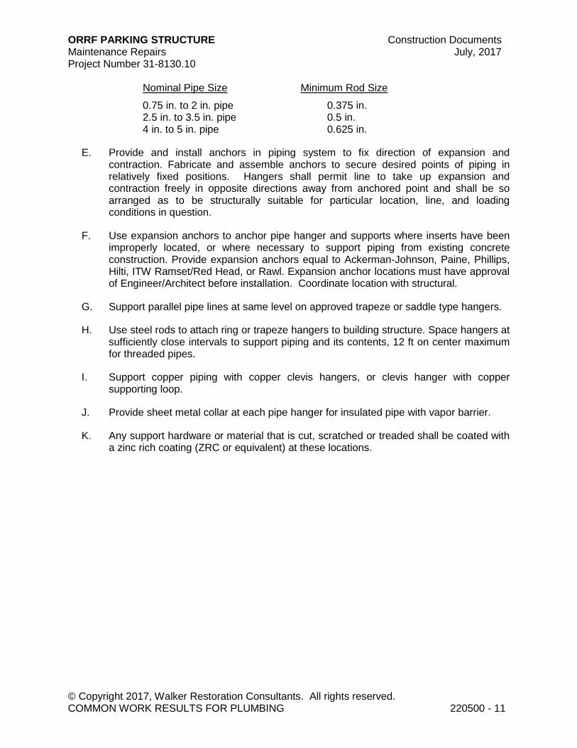
ORRF PARKING STRUCTURE Construction Documents Maintenance Repairs July, 2017 Project Number 31-8130.10
© Copyright 2017, Walker Restoration Consultants. All rights reserved. COMMON WORK RESULTS FOR PLUMBING 220500 - 11
Nominal Pipe Size Minimum Rod Size
0.75 in. to 2 in. pipe 0.375 in. 2.5 in. to 3.5 in. pipe 0.5 in. 4 in. to 5 in. pipe 0.625 in.
E. Provide and install anchors in piping system to fix direction of expansion and contraction. Fabricate and assemble anchors to secure desired points of piping in relatively fixed positions. Hangers shall permit line to take up expansion and contraction freely in opposite directions away from anchored point and shall be so arranged as to be structurally suitable for particular location, line, and loading conditions in question.
F. Use expansion anchors to anchor pipe hanger and supports where inserts have been improperly located, or where necessary to support piping from existing concrete construction. Provide expansion anchors equal to Ackerman-Johnson, Paine, Phillips, Hilti, ITW Ramset/Red Head, or Rawl. Expansion anchor locations must have approval of Engineer/Architect before installation. Coordinate location with structural.
G. Support parallel pipe lines at same level on approved trapeze or saddle type hangers.
H. Use steel rods to attach ring or trapeze hangers to building structure. Space hangers at sufficiently close intervals to support piping and its contents, 12 ft on center maximum for threaded pipes.
I. Support copper piping with copper clevis hangers, or clevis hanger with copper supporting loop.
J. Provide sheet metal collar at each pipe hanger for insulated pipe with vapor barrier.
K. Any support hardware or material that is cut, scratched or treaded shall be coated with a zinc rich coating (ZRC or equivalent) at these locations.

ORRF PARKING STRUCTURE Construction Documents Maintenance Repairs July, 2017 Project Number 31-8130.10
© Copyright 2017, Walker Restoration Consultants. All rights reserved. COMMON WORK RESULTS FOR PLUMBING 220500 - 12
3.6 CUTTING AND PATCHING
A. General: Perform cutting and patching in accordance with Division 01 Section "Cutting and Patching". In addition to the requirements specified in Division 01, the following requirements apply:
1. Protection of Installed Work: During cutting and patching operations, protect adjacent installations.
2. Perform cutting, fitting, and patching of mechanical equipment and materials required to:
a. Uncover Work to provide for installation of improperly scheduled Work. b. Remove and replace defective Work. c. Remove and replace Work not conforming to requirements of the Contract
Documents. d. Remove samples of installed Work as specified for testing. e. Install equipment and materials in structures. f. Upon written instructions from the Engineer/Architect, uncover and restore
Work to provide for Architect/Engineer observation of concealed Work.
B. Cut, remove and legally dispose of selected mechanical equipment, components, and materials as indicated, including but not limited to removal of mechanical piping, heating units, and trim, and other mechanical items made obsolete by the new Work.
1. Protect the structure, furnishings, finishes, and adjacent materials not indicated or scheduled to be removed.
2. Provide and maintain temporary partitions or dust barriers adequate to prevent the spread of dust and dirt to adjacent areas.
3. Patch finished surfaces and building components using new materials specified for the original installation and experienced Installers. Installers' qualifications refer to the materials and methods required for the surface and building components being patched.
a. Refer to Division 01 Section "Reference Standards and Definitions" for definition of "experienced Installer".
4. Respective trades will provide openings in floors, walls, and other members as required for installation of piping and equipment, provided that necessary information regarding such openings is furnished by contractor in timely manner.
5. If contractor fails to provide information regarding required openings, cutting and repairing of completed Work will be performed by respective trades at expense of contractor.
6. Seal all such openings in accordance with Division 07 Section "Joint Sealants." 7. Cut, channel, chase, and drill floors, walls, partitions, ceilings, and other surfaces
necessary for mechanical installations only with written approval of Engineer/Architect. Perform cutting by skilled mechanics of the trades involved.
8. Repair cut surfaces to match adjacent surfaces.
3.7 LABELING AND IDENTIFYING
ORRF PARKING STRUCTURE Construction Documents Maintenance Repairs July, 2017 Project Number 31-8130.10
© Copyright 2017, Walker Restoration Consultants. All rights reserved. COMMON WORK RESULTS FOR PLUMBING 220500 - 13
A. Piping Systems: Install pipe markers on each system. Include arrows showing normal direction of flow.
1. Stenciled Markers: Complying with ASME A13.1. 2. Locate pipe markers wherever piping is exposed in finished spaces, machine
rooms, accessible maintenance spaces (shafts, tunnels, plenums), and exposed exterior locations as follows:
a. Near each valve and control device. b. Near each branch, excluding short take-offs for fixtures and terminal units.
Mark each pipe at branch, where flow pattern is not obvious. c. Near locations where pipes pass through walls, floors, ceilings, or enter
inaccessible enclosures. d. At access doors, manholes, and similar access points that permit view of
concealed piping. e. Near major equipment items and other points of origination and
termination. f. Spaced at a maximum of 50 ft (15m) intervals along each run. Reduce
intervals to 25 ft (7.6 m) in congested areas of piping and equipment.
B. Adjusting: Relocate identifying devices which become visually blocked by work of this Division or other Divisions.
3.8 PAINTING AND FINISHING
A. Refer to Division 09 Section "Painting" for field painting requirements.
B. Damage and Touch Up: Repair marred and damaged factory-painted finishes with materials and procedures to match original factory finish.
3.9 CONCRETE BASES
A. Construct concrete equipment bases of dimensions indicated, but not less than 4 in. (101 mm) larger than supported unit in both directions. Follow supported equipment manufacturer's setting templates for anchor bolt and tie locations. Use 3000-psi (20.70MPa), 28-day compressive strength concrete and reinforcement as specified in Division 03 Section "Cast-in-Place Concrete".
3.10 TESTING AND GUARANTEE
A. Testing:
1. Take out all necessary permits, arrange for all required inspections, and pay all fees and expenses associated with performing Mechanical Work.
2. Test all piping systems at full operating pressure under normal conditions of use in accordance with requirements of Water Department, Board of Health, Fire Department, and all other authorities having jurisdiction. As a minimum, the

ORRF PARKING STRUCTURE Construction Documents Maintenance Repairs July, 2017 Project Number 31-8130.10
© Copyright 2017, Walker Restoration Consultants. All rights reserved. COMMON WORK RESULTS FOR PLUMBING 220500 - 14
water supply system shall be tested at 125 psi for 4 hrs, the sewer system at 5 psi for 15 minutes, natural gas at 100 psi for 2 hours, and the standpipe system at 225 psi for 2 hrs.
3. Provide all instruments for making tests. 4. Perform tests on following systems:
a. Sewer System.
5. Test all parts of system in presence of Contractor, Engineer/Architect, Owner and Authority having jurisdiction for sufficient period of time to permit complete examination and inspection.
6. Successfully test all concealed piping before its being permanently covered up. 7. Remedy all defects in materials or workmanship which appear during test or
retest of system.
B. Guarantee:
1. In addition to any specific guarantee called for by Specifications, furnish to Owner written guarantee against defects in materials, workmanship for all apparatus and materials furnished, and for entire workmanship of installation for period of 1 yr from date of acceptance of Work.
2. During guarantee period and without expense to Owner, repair all defects in workmanship or material provided under this Section.
END OF SECTION 220500
© Copyright 2017. All rights reserved. No part of this document may be reproduced in any form or by any means without permission from Walker Restoration Consultants.

ORRF PARKING STRUCTURE Construction Documents Maintenance Repairs July, 2017 Project Number 31-8130.10
© Copyright 2017, Walker Restoration Consultants. All rights reserved. FACILITY STORM DRAINAGE PIPING 221413 - 1
SECTION 221413 - FACILITY STORM DRAINAGE PIPING
PART 1 - GENERAL
1.1 RELATED DOCUMENTS
A. Drawings and general provisions of the Contract, including General and Supplementary Conditions and Division 01 Specification Sections, apply to this Section.
1.2 SUMMARY
A. In accordance with Contract Documents, furnish all labor equipment, and materials to install domestic water, and storm sewer plumbing facility.
B. This Section includes plumbing piping systems as indicated on the Drawings. Systems include the following:
1. Drainage and vent systems.
C. Related Sections: Following Sections contain requirements that relate to this Section:
1. Division 22 Section "Common Work Results for Plumbing".
1.3 PERFORMANCE REQUIREMENTS
A. Provide components and installation capable of producing piping systems with the following minimum working pressure ratings, except where indicated otherwise:
1. Storm Drainage Systems: 10-ft head of water.
1.4 SUBMITTALS
A. General: Submit the information specified in the submittals Section of "Basic Mechanical Requirements" in accordance with Conditions of Contract and Division 01 Specifications Section.
B. See requirements of Division 01 Section, “Submittal Procedures,” Part 1 heading, “Submittal Procedures,” for limits to resubmittals.
C. See requirements of Division 01 Section, “Submittal Procedures,” Part 2 heading, “Requests for Information,” for RFI constraints.
PART 2 - PRODUCTS
ORRF PARKING STRUCTURE Construction Documents Maintenance Repairs July, 2017 Project Number 31-8130.10
© Copyright 2017, Walker Restoration Consultants. All rights reserved. FACILITY STORM DRAINAGE PIPING 221413 - 2
2.1 GENERAL
A. See Division 22 Section "Common Work Results for Plumbing" for acceptable products and manufacturers.
2.2 MATERIALS
A. General:
1. Provide new materials of the best grade and quality.
B. Pipe:
1. Drainage:
a. Cast iron: (Storm drainage 15” and smaller)
1) Buried underground inside and to point 5 ft outside building: Service weight bell and spigot type, ASTM A74.
2) Above ground: Cast iron "No Hub", ASTM A888.
b. Reinforced Concrete (Storm drainage larger than 15”)
C. Fittings and Joints:
1. Nipples: Same material as pipe on which they are used. Avoid use of close nip-ples if possible.
2. Fittings for cast-iron soil pipe: Correspond to pipe in material, ASTM A74. 3. Joints in buried cast-iron pipe: Approved rubber gaskets. 4. Fittings for copper drainage piping: Cast copper fittings, ASA B16.23. Sweat
solder joints with lead-free solder.
D. Floor and Trench Drains: Heavy duty cast-iron with coated, heavy duty, vandal-proof grate and sediment buckets. Size, connection type and additional options are as specified on Drawings.
1. Acceptable Manufacturers:
a. Josam b. Smith. c. Wade. d. Zurn. e. Ancon.
E. Backwater Valves: Coated cast iron backwater valve, plastic ball float, elastomer seat, bronze cage and threaded or spigot outlet connection:
1. Acceptable Manufacturers:
ORRF PARKING STRUCTURE Construction Documents Maintenance Repairs July, 2017 Project Number 31-8130.10
© Copyright 2017, Walker Restoration Consultants. All rights reserved. FACILITY STORM DRAINAGE PIPING 221413 - 3
a. Josam 1000 Series. b. Smith 7000 Series. c. Zurn Z-1099 Series. d. Ancon BV 230-R.
F. Cleanouts:
1. In conductor risers: Coated cast iron cleanout tee with hub and spigot connec-tions and coated cast iron plug with internal gasket seal for installation in unfin-ished areas. Where finished appearance in wall installation is required, use in conjunction with access cover or box:
a. Acceptable manufacturers:
1) Josam 58510 Series. 2) Smith 4510 Series. 3) Wade W-8560 Series. 4) Zurn Z-1400 Series. 5) Ancon CO-460.
2. In floors in structure: Coated cast iron, adjustable housing, floor cleanout, spigot or no-hub connection with internal gasketed cleanout plug and adjustable hous-ing with heavy duty, secured (vandalproof) scoriated round cast iron tractor cover for heavy traffic for installation flush with finished floor:
a. Acceptable manufacturers:
1) Josam 56060 Series. 2) Smith 4240 Series. 3) Wade W-6000-Z and W-7000-Z Series. 4) Zurn Z-1420-25. 5) Ancon C-200-RX.
3. In floors and walls in finished areas: Provide with flush brass ring and covers, chrome plates, screwed to plug and set level and flush with floor or wall.
G. Expansion Joints for Rain Water Collectors: Vertical expansion joint, coated cast iron body and packing gland and siliconed bronze sleeve with preformed neoprene packing gasket:
1. Acceptable manufacturers:
a. Josam 26200 Series. b. Smith 1710 Series. c. Wade W-3900 Series. d. Zurn Z-190.
H. Clamps, rods and all support material and hardware shall be hot dipped galvanized or stainless steel.
ORRF PARKING STRUCTURE Construction Documents Maintenance Repairs July, 2017 Project Number 31-8130.10
© Copyright 2017, Walker Restoration Consultants. All rights reserved. FACILITY STORM DRAINAGE PIPING 221413 - 4
PART 3 - EXECUTION
3.1 INSTALLATION
A. Sewer Systems:
1. Provide piping, floor drains and accessories, backwater valve, catch basins, manholes, covers, pumps, or any other required components complete to existing storm, sanitary or combined sewer on site.
2. Pitch all horizontal lines 0.125 in. per ft minimum. 3. Install backwater valves wherever shown on Drawings. 4. All cast-iron pipe buried in ground shall have firm bearing along entire length of
undisturbed earth, or on compacted sand. Pipe on fill or loose soil shall be supported on brick or concrete piers, and then firmly embedded in earth. At foot of each stack, block concrete foundation shall be provided for stack, block concrete foundation shall be provided for stack to rest on.
5. Waste piping passing through foundation wall or under footing shall be provided with iron pipe sleeve built into masonry or concrete. Sleeve shall be 2 pipe sizes greater than pipe passing through.
6. Provide and set cleanouts for all drains inside building at ends of all horizontal branches, at base of all stacks, and all points where so indicated, called for, or necessary to clear line of obstructions.
7. Provide cast-iron Y-branch with cleanout at side in locations where cleanout will not be readily accessible due to interference of wall or other member.
8. Provide plugs for cleanouts. 9. Provide Owner with wrench to use for countersunk nuts on cleanout plugs. 10. Vent piping from main sanitary waste and fixture vents shall be extended as
shown, 1 ft 9 in. above roof and flashed. Flashing to have 18 in. x 18 in. 4-pound lead base and extended up to top of stack and turned down to stack.
3.2 COMMISSIONING
A. Preparation: Perform following checks before start-up:
1. Systems tests are complete. 2. Damaged and defective specialties and accessories have been replaced or
repaired. 3. There is clear space for servicing of specialties.
B. Before operating systems, perform these steps:
1. Close drain valves, hydrants, and hose bibbs. 2. Open valves to full open position. 3. Remove and clean strainers. 4. Verify drainage and vent piping are clear of obstructions. Flush with water until
clear.

ORRF PARKING STRUCTURE Construction Documents Maintenance Repairs July, 2017 Project Number 31-8130.10
© Copyright 2017, Walker Restoration Consultants. All rights reserved. FACILITY STORM DRAINAGE PIPING 221413 - 5
C. Test and certify systems in accordance with Division 22 Section "Common Work Results for Plumbing".
3.3 ADJUSTING
A. Adjust operation and correct deficiencies discovered during commissioning.
3.4 DEMONSTRATION
A. Train Owner's maintenance personnel on procedures related to startup and servicing of interceptors.
3.5 PROTECTION
A. Protect drains during remainder of construction period to avoid clogging with dirt and debris and to prevent damage from traffic and construction work.
B. Place plugs in ends of uncompleted piping at end of day or when work stops.
END OF SECTION 221413
© Copyright 2017. All rights reserved. No part of this document may be reproduced in any form or by any means without permission from Walker Restoration Consultants.


MAINTENANCE REPAIRS
LOCATION MAP
OAK PARK, ILLINOIS
OPRF PARKING STRUCTURE
Copyright 2016. All rights reserved. No part of this document may be reproduced in any form or by any means without permission from Walker Parking Consultants/Engineers, Inc.
DATE ISSUED
JULY 26, 2017
R-000 COVER SHEET
R-001 GENERAL NOTES, W.I. SCHEDULE & LEGEND
R-101 LOWER LEVEL FLOOR AND REFLECTED CEILING PLAN
R-102 LEVEL 1 FLOOR AND REFLECTED CEILING PLAN
R-103 LEVEL 2 FLOOR PLAN
R-201 ELEVATIONS
R-501 REPAIR DETAILS
R-502 REPAIR DETAILS
NORTH
WALKERRESTORATION CONSULTANTS
505 Davis Road
Elgin, IL 60123
847.697.2640 Ph
847.697.7439 Fax
www.walkerrestoration.com
PROJECT No.: 31-8130.10
PROJECT
SITE

FD
FD
GENERAL LEGEND
EXPANSION JOINT
(EJ)
FLOOR SPALL OR DELAMINATION
CEILING SPALL OR DELAMINATION
EXISTING FLOOR DRAIN (FD)
NEW SUPPLEMENTAL FLOOR DRAIN (FD)
X.X.X
WORK ITEM NUMBER
CLARIFICATION DETAIL NUMBER
WORK ITEM IDENTIFICATION LEGEND
NOTES:
1. NOT ALL WORK ITEMS HAVE DETAILS.
2. SEE SPECIFICATIONS FOR ADDITIONAL INFORMATION.
XXX
WORK ITEM NOTE
(SEE ABBREVIATIONS)
GENERAL NOTES: WORK ITEM SCHEDULE:
R-001
GENERAL NOTES,
W.I. SCHEDULE &
LEGEND
JAP
LCS
SHEET TITLE:
DE
SC
RIP
TIO
N
IS
SU
ED
:
NO
.D
AT
E
PROJECT NO:
DRAWN BY:
CHECKED BY:
31-8130.10
J:\31-8130-10_O
AK
_P
AR
K_O
PR
F_C
D_&
_C
A\A
CA
D\8130R
-001.D
WG
7/25/2017 9:51:13 A
M P
ER
EZ
, JO
SE
A
Copyright 2017. All rights reserved. No part of this document may be reproduced in any form or by any means without permission from Walker Restoration Consultants, Inc.
ILLIN
OIS
MA
IN
TE
NA
NC
E R
EP
AIR
S
OP
RF
P
AR
KIN
G S
TR
UC
TU
RE
OA
K P
AR
K,
WA
LK
ER
RESTO
RATIO
N C
ON
SU
LTAN
TS
505
D
avis R
oad
Elgin, IL 6
01
23
847
.69
7.2
640
P
h
847
.69
7.7
439
F
ax
ww
w.w
alke
rre
stora
tion.co
m
DA
TE
IS
SU
ED
07-26-2017

1 1.4 2 3 4 5 6 7 8 9 10 11 11.6 12
A
B
C
B.8
1 1.4 2 3 4 5 6 7 8 9 10 11 11.6 12
A
B
C
B.8
1
1
LOWER LEVEL FLOOR PLAN
1
NORTH
4'-11" 15'-5" 27'-0" 30'-0" 30'-0" 30'-0" 30'-0" 30'-0" 30'-0" 30'-0" 30'-0" 30'-0" 27'-0" 15'-5" 4'-11"
60'-0"
60'-0"
LOWER LEVEL
REFLECTED CEILING PLAN
2
NORTH
4'-11" 15'-5" 27'-0" 30'-0" 30'-0" 30'-0" 30'-0" 30'-0" 30'-0" 30'-0" 30'-0" 30'-0" 27'-0" 15'-5" 4'-11"
60'-0
"6
0'-0
"
1
1
45.8
6.66.66.6
45.1
TYP
FD
25.6
TYP
45.745.6
11.6
25.7
45.5
SHEET NOTES:
1. CONTRACTOR IS RESPONSIBLE FOR DETERMING THE ACTUAL EXTENT AND
LOCATIONS OF REPAIR AREAS IN ACCORDANCE WITH THE SPECIFICATIONS.
WORK ITEM IS SHOWN ONLY TO REPRESENT THE TYPES OF REPAIRS.
2. DRAWINGS ARE BASED ON LIMITED INFORMATION. CONTRACTOR SHALL
MAKE SUCH INVESTIGATIONS AS IT DEEMS NECESSARY IN ADVANCE OF
BIDDING. CONTRACTOR SHALL PROMPTLY NOTIFY THE OWNER'S
REPRESENTATIVE, IN WRITING, OF ANY DISCREPANCIES FOUND BETWEEN
DRAWINGS AND FIELD CONDITIONS PRIOR TO SUBMISSION OF BID.
3. REFER TO SPECIFICATION SECTION 020010 FOR DESCRIPTION OF WORK
ITEMS.
4. THE CONTRACTOR SHALL REVIEW ALL EXISTING CONDITIONS TO
DETERMINE ALL ELECTRICAL AND MECHANICAL SERVICES AND UTILITIES
AFFECTED BY THE REPAIR WORK. ELECTRICAL CONDUITS AND LIGHT
FIXTURES ARE TO BE MAINTAINED. MAKE NECESSARY TEMPORARY
CONNECTIONS TO MAINTAIN SERVICES TO ALL AREAS OF THE PARKING
STRUCTURE AFFECTED BY THE REPAIR WORK.
5. REFER TO SHEET R-001 FOR LEGEND, GENERAL NOTES AND W.I. SCHEDULE.
6. REFER TO SHEETS R-501 AND R-502 FOR REPAIR DETAILS.
45.8
(E.J. PLATES)
R-101
LOWER LEVEL
& REFLECTED
CEILING PLAN
JAP
LCS
SHEET TITLE:
DE
SC
RIP
TIO
N
IS
SU
ED
:
NO
.D
AT
E
PROJECT NO:
DRAWN BY:
CHECKED BY:
31-8130.10
J:\31-8130-10_O
AK
_P
AR
K_O
PR
F_C
D_&
_C
A\A
CA
D\8130R
-101.D
WG
7/13/2017 1:48:09 P
M P
ER
EZ
, JO
SE
A
Copyright 2017. All rights reserved. No part of this document may be reproduced in any form or by any means without permission from Walker Restoration Consultants, Inc.
ILLIN
OIS
MA
IN
TE
NA
NC
E R
EP
AIR
S
OP
RF
P
AR
KIN
G S
TR
UC
TU
RE
OA
K P
AR
K,
WA
LK
ER
RESTO
RATIO
N C
ON
SU
LTAN
TS
50
5 D
avis R
oa
d
Elg
in
, IL
60
123
84
7.6
97.264
0 P
h
84
7.6
97.743
9 F
ax
ww
w.w
alkerrestoration.com
DA
TE
IS
SU
ED
07-26-2017
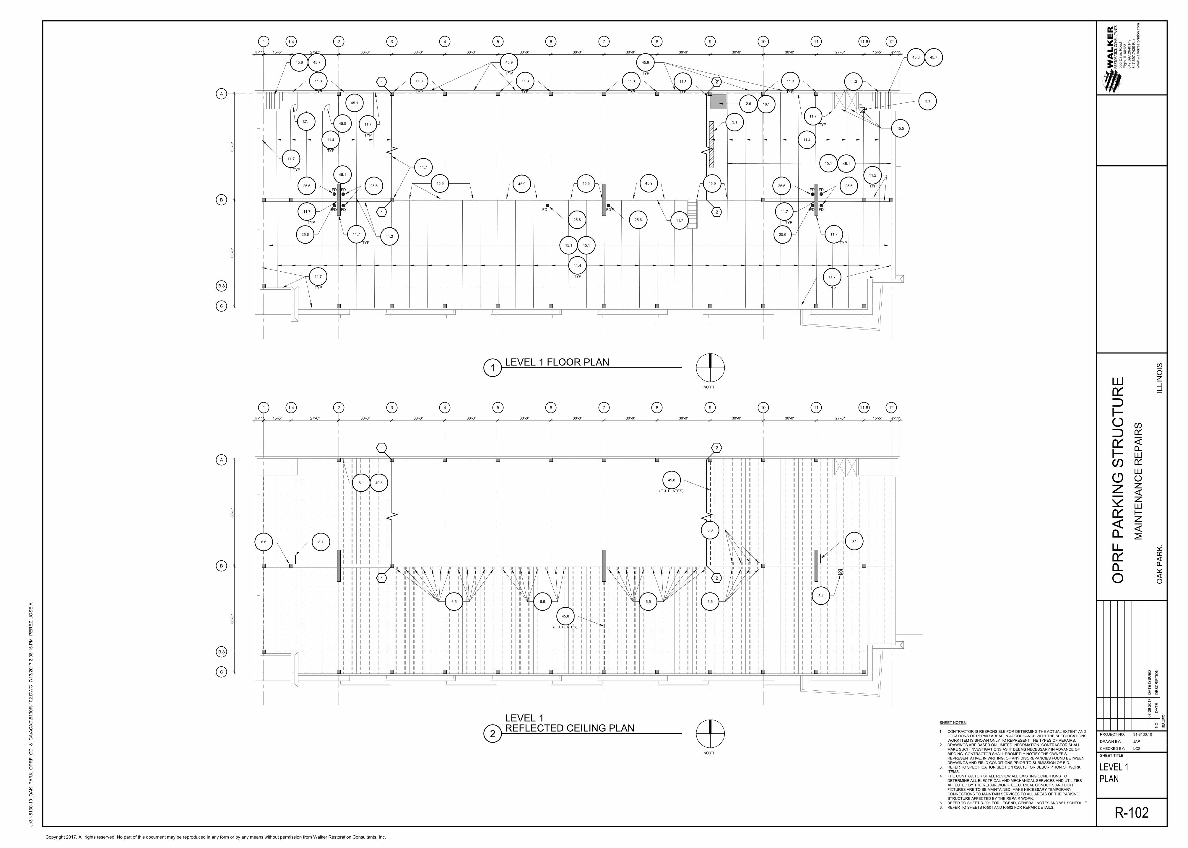
1 1.4 2 3 4 5 6 7 8 9 10 11 11.6 12
A
B
C
B.8
1 1.4 2 3 4 5 6 7 8 9 10 11 11.6 12
A
B
C
B.8
2
2
1
1
2
2
1
1
LEVEL 1 FLOOR PLAN
1
NORTH
4'-11" 15'-5" 27'-0" 30'-0" 30'-0" 30'-0" 30'-0" 30'-0" 30'-0" 30'-0" 30'-0" 30'-0" 27'-0" 15'-5" 4'-11"
60'-0"
60'-0"
LEVEL 1
REFLECTED CEILING PLAN
2
NORTH
4'-11" 15'-5" 27'-0" 30'-0" 30'-0" 30'-0" 30'-0" 30'-0" 30'-0" 30'-0" 30'-0" 30'-0" 27'-0" 15'-5" 4'-11"
60'-0
"6
0'-0
"
11.3
SHEET NOTES:
1. CONTRACTOR IS RESPONSIBLE FOR DETERMING THE ACTUAL EXTENT AND
LOCATIONS OF REPAIR AREAS IN ACCORDANCE WITH THE SPECIFICATIONS.
WORK ITEM IS SHOWN ONLY TO REPRESENT THE TYPES OF REPAIRS.
2. DRAWINGS ARE BASED ON LIMITED INFORMATION. CONTRACTOR SHALL
MAKE SUCH INVESTIGATIONS AS IT DEEMS NECESSARY IN ADVANCE OF
BIDDING. CONTRACTOR SHALL PROMPTLY NOTIFY THE OWNER'S
REPRESENTATIVE, IN WRITING, OF ANY DISCREPANCIES FOUND BETWEEN
DRAWINGS AND FIELD CONDITIONS PRIOR TO SUBMISSION OF BID.
3. REFER TO SPECIFICATION SECTION 020010 FOR DESCRIPTION OF WORK
ITEMS.
4. THE CONTRACTOR SHALL REVIEW ALL EXISTING CONDITIONS TO
DETERMINE ALL ELECTRICAL AND MECHANICAL SERVICES AND UTILITIES
AFFECTED BY THE REPAIR WORK. ELECTRICAL CONDUITS AND LIGHT
FIXTURES ARE TO BE MAINTAINED. MAKE NECESSARY TEMPORARY
CONNECTIONS TO MAINTAIN SERVICES TO ALL AREAS OF THE PARKING
STRUCTURE AFFECTED BY THE REPAIR WORK.
5. REFER TO SHEET R-001 FOR LEGEND, GENERAL NOTES AND W.I. SCHEDULE.
6. REFER TO SHEETS R-501 AND R-502 FOR REPAIR DETAILS.
6.66.66.6 6.6
8.1
8.4
11.4
TYP
11.4
TYP
15.1 45.1
FD FD
25.6 25.6
11.7
11.7
FDFD
FDFD
25.625.6
11.7
11.311.311.3 11.3
11.7
45.945.9
45.9
45.9
45.9
FD FD
FD FD
25.6 25.6
11.4
11.7
TYP
11.311.3
45.745.6
45.745.6
11.7
45.9
45.5
3.1
15.1
45.1
11.2
11.7
3.1
2.6
16.1
45.9
45.1
37.1
45.1
11.2
TYP
TYP
45.9
TYP
TYP TYP TYP TYP TYP
TYP
45.8
(E.J. PLATES)
8.1
5.1 40.5
6.6
45.8
(E.J. PLATES)
6.6
TYP
TYP
25.6
11.7
TYP
TYP
11.7
TYP
45.5
11.7
TYP
25.6
11.7
TYP
TYP
TYP
R-102
LEVEL 1
PLAN
JAP
LCS
SHEET TITLE:
DE
SC
RIP
TIO
N
IS
SU
ED
:
NO
.D
AT
E
PROJECT NO:
DRAWN BY:
CHECKED BY:
31-8130.10
J:\31-8130-10_O
AK
_P
AR
K_O
PR
F_C
D_&
_C
A\A
CA
D\8130R
-102.D
WG
7/13/2017 2:08:15 P
M P
ER
EZ
, JO
SE
A
Copyright 2017. All rights reserved. No part of this document may be reproduced in any form or by any means without permission from Walker Restoration Consultants, Inc.
ILLIN
OIS
MA
IN
TE
NA
NC
E R
EP
AIR
S
OP
RF
P
AR
KIN
G S
TR
UC
TU
RE
OA
K P
AR
K,
WA
LK
ER
RESTO
RATIO
N C
ON
SU
LTAN
TS
50
5 D
avis R
oa
d
Elg
in
, IL
60
123
84
7.6
97.264
0 P
h
84
7.6
97.743
9 F
ax
ww
w.w
alkerrestoration.com
DA
TE
IS
SU
ED
07-26-2017

3.1
SIM
11.4
LEVEL 2 FLOOR PLAN
1
NORTH
1 1.4 2 3 4 5 6 7 8 9 10 11 11.6 12
A
B
C
B.8
2
2
11.3
3.1
TYP
11.1
TAR
FD FD
FD
11.3
11.6
11.3
11.6
11.3
TAR
4'-11" 15'-5" 27'-0" 30'-0" 30'-0" 30'-0" 30'-0" 30'-0" 30'-0" 30'-0" 30'-0" 30'-0" 27'-0" 15'-5" 4'-11"
60'-0"
60'-0"
11.3
TYP
11.7
11.3
11.7
3.1
TYP
11.7
11.1
TAR
3.1
25.2
11.4
TYP
40.2
25.3
3.1
3.1
40.2
11.1
11.3
11.3
10.3
11.1
TAR
11.7
11.4
TYP
3.5
TYP
3.5
TYP
3.5
TYP
3.5
TYP
SHEET NOTES:
1. CONTRACTOR IS RESPONSIBLE FOR DETERMING THE ACTUAL EXTENT AND
LOCATIONS OF REPAIR AREAS IN ACCORDANCE WITH THE SPECIFICATIONS.
WORK ITEM IS SHOWN ONLY TO REPRESENT THE TYPES OF REPAIRS.
2. DRAWINGS ARE BASED ON LIMITED INFORMATION. CONTRACTOR SHALL
MAKE SUCH INVESTIGATIONS AS IT DEEMS NECESSARY IN ADVANCE OF
BIDDING. CONTRACTOR SHALL PROMPTLY NOTIFY THE OWNER'S
REPRESENTATIVE, IN WRITING, OF ANY DISCREPANCIES FOUND BETWEEN
DRAWINGS AND FIELD CONDITIONS PRIOR TO SUBMISSION OF BID.
3. REFER TO SPECIFICATION SECTION 020010 FOR DESCRIPTION OF WORK
ITEMS.
4. THE CONTRACTOR SHALL REVIEW ALL EXISTING CONDITIONS TO
DETERMINE ALL ELECTRICAL AND MECHANICAL SERVICES AND UTILITIES
AFFECTED BY THE REPAIR WORK. ELECTRICAL CONDUITS AND LIGHT
FIXTURES ARE TO BE MAINTAINED. MAKE NECESSARY TEMPORARY
CONNECTIONS TO MAINTAIN SERVICES TO ALL AREAS OF THE PARKING
STRUCTURE AFFECTED BY THE REPAIR WORK.
5. REFER TO SHEET R-001 FOR LEGEND, GENERAL NOTES AND W.I. SCHEDULE.
6. REFER TO SHEETS R-501 AND R-502 FOR REPAIR DETAILS.
TYP
74.7
(ON TOP OF WALL)
74.7
(TYP 5'-0")
74.7
(TYP 5'-0")
2.6 16.1
74.7
(TYP 5'-0")
74.7
(TYP 5'-0")
37.1
96.4 45.6 45.7
2.6 16.1
11.2
25.6
25.6
15.1 45.1
15.1 45.1
15.1 45.1
TYP
TYP
25.2
25.3
25.6
25.6
11.3 11.7
11.7
40.2
40.2
40.2
96.4
45.6 45.7
45.5
(INCLUDE CANOPY)
25.6
25.6
3.1
TYP
11.2
74.7
(TYP 5'-0")
45.9
TYP
45.9
TYP
40.2
40.2
40.2
40.2
40.2
45.9
TYP
11.5
TAR
11.5
TAR
2.6 16.1
91.5
(ON PRECAST PANELS)
TYP
35.1
R-103
LEVEL 2 FLOOR
PLAN
JAP
LCS
SHEET TITLE:
DE
SC
RIP
TIO
N
IS
SU
ED
:
NO
.D
AT
E
PROJECT NO:
DRAWN BY:
CHECKED BY:
31-8130.10
J:\31-8130-10_O
AK
_P
AR
K_O
PR
F_C
D_&
_C
A\A
CA
D\8130R
-103.D
WG
7/13/2017 2:10:30 P
M P
ER
EZ
, JO
SE
A
Copyright 2017. All rights reserved. No part of this document may be reproduced in any form or by any means without permission from Walker Restoration Consultants, Inc.
ILLIN
OIS
MA
IN
TE
NA
NC
E R
EP
AIR
S
OP
RF
P
AR
KIN
G S
TR
UC
TU
RE
OA
K P
AR
K,
WA
LK
ER
RESTO
RATIO
N C
ON
SU
LTAN
TS
50
5 D
avis R
oa
d
Elg
in
, IL
60
123
84
7.6
97.264
0 P
h
84
7.6
97.743
9 F
ax
ww
w.w
alkerrestoration.com
DA
TE
IS
SU
ED
07-26-2017

1 1.4 2 3 4 5 6 7 8 9 10 11 11.6 12
SOUTH ELEVATION
1
74.7
TYP
74.7
TYP
83.674.7
TYP
11.3
TYP
11.3
TYP
11.3 11.3
TYP
11.3
TYP
11.3
TYP
74.7
TYP
74.7
TYP
12 11.6
74.7
TYP
11.3
TYP
NORTH ELEVATION
1
TYP
(NOT TO SCALE)
(NOT TO SCALE)
74.7
TYP
74.7
TYP
11.3
TYP
SECTION OF WALL TO BE
REPLACED. TOOTH IN
NEW BRICK INTO
EXISTING BRICK. MATCH
EXISTING BRICK COLOR.35.1
11.3
TYP
R-201
ELEVATIONS
JAP
LCS
SHEET TITLE:
DE
SC
RIP
TIO
N
IS
SU
ED
:
NO
.D
AT
E
PROJECT NO:
DRAWN BY:
CHECKED BY:
31-8130.10
J:\31-8130-10_O
AK
_P
AR
K_O
PR
F_C
D_&
_C
A\A
CA
D\8130R
-201.D
WG
7/13/2017 2:51:10 P
M P
ER
EZ
, JO
SE
A
Copyright 2017. All rights reserved. No part of this document may be reproduced in any form or by any means without permission from Walker Restoration Consultants, Inc.
ILLIN
OIS
MA
IN
TE
NA
NC
E R
EP
AIR
S
OP
RF
P
AR
KIN
G S
TR
UC
TU
RE
OA
K P
AR
K,
WA
LK
ER
RESTO
RATIO
N C
ON
SU
LTAN
TS
505
D
avis R
oad
Elgin, IL 6
01
23
847
.69
7.2
640
P
h
847
.69
7.7
439
F
ax
ww
w.w
alke
rre
stora
tion.co
m
DA
TE
IS
SU
ED
07-26-2017
REMOVE CONCRETE WITHIN SECTION
SHOWN CROSS-HATCHED
P/C TEE
DELAMINATION
REMOVAL LIMITS
PERIMETER 3/4"
(TYP.)
SAW CUT PATCH
(VARIES)
SPALL OR
LATEX MODIFIED CONCRETE
ORIGINAL SURFACE
4"±
2" - 3"
W.W.F. TO REMAIN (TYP.), LOCATION
APPROXIMATE. CLEAN ALL EXPOSED
MESH. REMOVE WWF WHERE MESH HAS
LESS 1/2" OF COVER (MESH DOES NOT
REQUIRE EPOXY COATING). PROVIDE 3/4"
CLEARANCE AROUND ALL EXPOSED
REINF. WHERE REQ'D AS SPECIFIED IN
SECTION "SURFACE PREPARATION FOR
PATCHING".
FLOOR REPAIR
3.1
NOTES:
1. REPLACEMENT OF JOINT SEALANT IS INCIDENTAL WHERE PATCH ABUTS OR GOES
THROUGH A JOINT. SEE DETAIL 11.2.
4"±
12"±
P/C TEE
1" M
IN
.
GRIND OR CUT-OFF STEEL LIFING LOOP
ROPE. EPOXY COAT TOP OF ROPE, WHERE
REQUIRED AS SPECIFIED IN SECTION
"SURFACE PREPARATION FOR PATCHING"
LATEX MODIFIED CONCRETE
P/C TEE
SAW CUT PATCH
PERIMETER 3/4" (TYP.)
PLAN
SECTION
FLOOR REPAIR - LIFTING LOOPS
3.5
REMOVE ALL CONCRETE
MATERIAL FROM P/C TEE
REMOVAL LIMITS (TYP.)
SPALL OR DELAMINATION
REMOVE CONCRETE WITHIN
SECTIONS SHOWN SHADED, TYP.
GRIND OR SAW CUT PATCH
PERIMETER 1/2" (TYP.)
SHORING
PROVIDE
VA
RIE
S
2"-4"
(TYP.)
PROVIDE SHORING
2"-4"
VARIES
VARIES
SECTION "SURFACE PREPARATION FOR
REINF. WHERE REQ'D AS SPECIFIED IN
3/4" CLEARANCE AROUND ALL EXPOSED
COAT ALL EXPOSED REINF. PROVIDE
APPROXIMATE. CLEAN AND EPOXY
REINFORCEMENT (TYP.), LOCATIONS
TROWEL APPLIED
MORTAR OR SHOTCRETE
PATCHING".
P/C TEE (TYP.)
BEAM REPAIR
5.1
NOTES:
1. NUMBER AND LOCATION OF REINFORCEMENT SHOWN MAY DIFFER FROM ACTUAL FIELD CONDITIONS.
REMOVE CONCRETE WITHIN SECTIONS
SHOWN SHADED, TYP.
2"-4"
PATCHING".
AS SPECIFIED IN SECTION
"SURFACE PREPARATION FOR
LOCATIONS APPROXIMATE.
CLEAN AND EPOXY COAT
3/4" CLEARANCE AROUND ALL
ALL EXPOSED REINF. PROVIDE
EXPOSED REINF. WHERE REQ'D
REINFORCEMENT (TYP.),
2"-4"
(TYP.)
REMOVAL LIMITS
PATCH PERIMETER
GRIND OR SAW CUT
VA
RIE
S
1/2" (TYP.)
(TYP.)
SPALL OR DELAMINATION
(T
YP
IC
AL)
2'-0" S
Q.
MORTAR OR SHOTCRETE
TROWEL APPLIED
COLUMN REPAIR
6.1
NOTES:
1. NUMBER AND LOCATION OF REINFORCEMENT SHOWN MAY DIFFER FROM ACTUAL FIELD CONDITIONS.
P/C COLUMN
3"(±)
TROWEL APPLIED MORTAR
REINF. WHERE REQ'D AS SPECIFIED IN SECTION
PROVIDE 3/4" CLEARANCE AROUND ALL EXPOSED
CLEAN AND EXPOXY COAT ALL EXPOSED REINF.
REINFORCEMENT (TYP.) LOCATIONS APPROXIMATE
HATCHED
SECTIONS SHOWN CROSS-
REMOVE CONCRETE WITHIN
P/C BEAM
PROVIDE SHORING
"SURFACE PREPARATION FOR PATCHING". INSTALL
ANCHORS INTO EXISTING CONRETE TO HOLD PATCH
IN PLACE
OR SHOTCRETE
COLUMN REPAIR - HAUNCH
6.6
PROVIDE "TAPCON CONCRETE
SCREWS" AT 6" O.C., EMBED 2"
INTO EXISTING CONCRETE (4
PER HAUNCH MIN.)
NOTES:
1. NUMBER AND LOCATION OF REINFORCEMENT SHOWN MAY DIFFER FROM ACTUAL FIELD CONDITIONS.
REMOVAL LIMITS
SPALL OR DELAMINATION
PRESTRESSED TENDONS
EXISTING P/C TEE
GRIND OR SAW CUT
PATCH PERIMETER
1/2" (TYP.)
PROVIDE SHORING
1 1/2" MIN. COVER
SHOTCRETE MATERIAL
TROWEL APPLIED OR
VA
RIE
S
(TYP.) SEE NOTE 1.
4"±
2"-4"
EXISTING W.W.R.
REMOVE CONCRETE WITHIN
SECTION SHOWN
REINFORCEMENT (TYP.),
LOCATIONS APPROXIMATE.
CLEAN AND APPLY
CORROSION INHIBITOR TO
ALL EXPOSED REINF.
PROVIDE 3/4" CLEARANCE
AROUND ALL EXPOSED REINF.
WHERE REQ'D AS SPECIFIED
IN SECTION "SURFACE
PREPARATION FOR
PATCHING".
TEE STEM REPAIR
8.1
NOTES:
1. DO NOT CUT OR DAMAGE PRE-STRESSED TENDONS.
2. MAX PATCH LENGTH = 2'-0" FOR REMOVAL AND REPLACEMENT PRIOR TO CONTINUING PATCH.
P/C TEE (TYP.)
EXISTING W.W.R.
GRIND OR SAWCUT PATCH
PERIMETER (TYP.)
1 1/2"-2" (NOTE 1)
EXISTING SHEAR
CONNECTOR (SEE NOTE 2)
REMOVAL LIMITS
CONCRETE
SURFACE
SPALL OR
DELAMINATION (TYP.)
REMOVE CONCRETE
WITHIN SECTIONS SHOWN
CROSS-HATCHED (TYP.)
6" MIN.
4"±
VARIES
TROWEL APPLIED
MORTAR OR
SHOTCRETE
TEE FLANGE REPAIR
8.4
X X X X X X X X
NOTES:
1. SANDBLAST, RE-WELD AS REQUIRED AND EPOXY COAT ALL BROKEN TEE FLANGE SHEAR
CONNECTORS. SHEAR CONNECTORS AND TEE REINFORCEMENT SHOWN MAY DIFFER FROM
ACTUAL FIELD CONDITIONS.
3 1/2" MIN.
(TYP.)
2 1/2"
(TYP.)
1. CONTRACTOR SHALL, WITH MANUFACTURER, VERIFY FIELD INSTALLATION WIDTH BASED
NOTES:
FLOOR TO FLOOR
CONCRETE
SLAB (TYP.)
3/4
"
EXPANSION JOINT TO MATCH EXISTING
HEADER (TYP.)
ELASTOMERIC CONCRETE
CONCRETE HEADER TO
NEW LATEX MODIFIED
FORM OPENING
2. FLOOR SPALLS ADJACENT TO JOINT SHALL BE REPAIRED SIMILAR TO 3.1 COST
ON TEMPERATURE CONDITIONS.
SHALL BE INCLUDED IN THE COST OF THE JOINT.
3. ANGLE EXPANSION JOINT UP ONTO ALL CURBS.
VARIES
(SEE NOTE 1)
EXPANSION JOINT - ELASTOMERIC
10.3
1/2"
3/4
"
ROUT CRACK WITH 'V' BLADE
AND FILL W/ FLEXIBLE SEALANT.
INSTALL SEALANT 1/16" BELOW
ADJACENT SURFACES, OR
FLUSH W/ ADJACENT SURFACES
TO RECEIVE TRAFFIC COATING.
DO NOT OVERFILL JOINT.
EXISTING CONCRETE
EXISTING CRACK. CENTER
ROUTED GROOVE ON CRACK
RANDOM CRACK REPAIR
11.1
1/1
6"
3/4"±
1"
REMOVE EXISTING SEALANT,
PREPARE EDGE, AND FILL WITH
FLEXIBLE SEALANT. INSTALL
SEALANT EVENLY UNDER
MEMBRANE
CONCRETE SLAB
EXISTING JOINT. CENTER
ROUTED GROOVE ON JOINT
CONTROL JOINT SEALANT
11.2
CONCRETE SURFACE
BOND BREAKER
1/16"
1-1/4" MIN.
3/4"
1/16"
3/4"
TAPE (IF NEEDED)
CLOSE CELL BACKER
ROD (IF NEEDED)
REMOVE EXISTING SEALANT,
PREPARE EDGE, AND FILL WITH
FLEXIBLE SEALANT. INSTALL
SEALANT EVENLY AND RECESS
1/16" BELOW SURFACE. DO NOT
OVERFILL JOINT. (FILL EVENLY
UNDER MEMBRANE)
NOTE:
SANDBLAST CLEAN AND APPLY ZINC RICH PRIMER TO
ALL CORRODED SHEAR CONNECTORS IN JOINT.
TEE-TO-TEE JOINT SEALANT
11.4
EXIST CRACK
INTERIOR WALL FACE
NOTE 1
INTERIOR WALL FACE
TROWEL APPLIED MORTAR
NOTES 2 AND 3
EPOXY INJECTION
11.5
NOTES:
1. INSERT PACKERS INTO CLEAN DRILLED HOLE SO THAT TOP OF RUBBER SLEEVE IS BELOW
CONCRETE SURFACE.
2. AFTER GROUTING PROCEDURE IS COMPLETE, REMOVE PACKER AND FITTINGS FROM HOLE
AND REMOVE EXCESS GROUT FROM FACE OF WALL.
3. PATCH REMAINING HOLES WITH TROWEL APPLIED MORTAR. FILL ENTIRE HOLE FLUSH WITH
SURFACE OF THE WALL TO MATCH THE EXISTING CONDITION.
R-501
REPAIRDETAILS
JAP
LCS
SHEET TITLE:
DE
SC
RIP
TIO
N
IS
SU
ED
:
NO
.D
AT
E
PROJECT NO:
DRAWN BY:
CHECKED BY:
31-8130.10
J:\31-8130-10_O
AK
_P
AR
K_O
PR
F_C
D_&
_C
A\A
CA
D\8130R
-501.D
WG
7/13/2017 2:37:37 P
M P
ER
EZ
, JO
SE
A
Copyright 2017. All rights reserved. No part of this document may be reproduced in any form or by any means without permission from Walker Restoration Consultants, Inc.
ILLIN
OIS
MA
IN
TE
NA
NC
E R
EP
AIR
S
OP
RF
P
AR
KIN
G S
TR
UC
TU
RE
OA
K P
AR
K,
WA
LK
ER
RESTO
RATIO
N C
ON
SU
LTAN
TS
505
D
avis R
oad
Elgin, IL 6
01
23
847
.69
7.2
640
P
h
847
.69
7.7
439
F
ax
ww
w.w
alke
rre
stora
tion.co
m
DA
TE
IS
SU
ED
07-26-2017
VARIABLE
JOINT WIDTH,
1/2" TYP
EXISTING MORTAR TO
REMAIN.
NOTES:
1. REMOVE ALL EXISTING SEALANT AND BACKER MATERIAL (IF PRESENT).
2. USE NON-FLOWABLE SEALANT MATERIAL FOR VERTICAL SURFACES.
3. PRIME JOINT
4. INSTALL SEALANT EVENLY AND TOOL JOINT CONCAVE 1/16" BELOW EXISTING SURFACE.
5. WET TOOLING WILL NOT BE ALLOWED.
6. SUBMIT COLOR SAMPLES FOR APPROVAL PRIOR TO START OF WORK.
BACKER ROD
SEALANT (SEE NOTES)
EXIST CAPSTONE (TYP)
1/16
"
MAINTAIN SEALANT
THROAT DIMENSION 1/2
OF JOINT WIDTH.
3/4
"
GRIND BACK EXIST
MORTAR 3/4", AS REQ'D
CAPSTONE JOINT REPAIR
74.7
1'-0" M
AX
NO
TE
2
TH
IC
KN
ES
S O
F
EX
IS
TIN
G W
ALL
OR
C
EILIN
G
THICKNESS
OF WALL OR
CEILING
MID-POINT
V.I.F
.
EXISTING
CRACK
INJECTION PORT
DRILLED AT 45°
ANGLE TO CRACK
SEE NOTE 3. (TYP)
FLOOR LINE
SECTION A-A
AA
NOTES:
1. CLEAN SURFACE OF WALL TO IDENTIFY CRACK. DRILL INJECTION PORT AT A 45° ANGLE TO
INTERSECTCRACK AT THE MID-DEPTH OF THE WALL.
2. STAGGER DRILL HOLES FROM ONE SIDE OF THE CRACK TO THE OTHER AT A MAXIMUM 12" OC SPACING.
3. FLUSH DRILL HOLES w/CLEAN WATER.
EPOXY INJECTION
11.6
3/4
"
3/4"
EXISTING WALL, COLUMN, OR CURB FACE
EXISTING FINISHED
FLOOR SURFACE
SEALANT MATERIAL
1/2" MIN THROAT
SEE NOTE 1.
COVE SEALANT
11.7
NOTES:
1. REMOVE EXISTING COVE SEALANT MATERIAL IF PRESENT. PREPARE SURFACE PER
SPECIFICATIONS.
VERTICAL SURFACE
(WALL OR COLUMNS)
LIMITS OF SURFACE
PREPARATION
CONTRACTOR TO PROVIDE
STRAIGHT FINISHED LINE
PROVIDE 4" WIDE DETAIL
COAT CENTERED OVER
ALL CRACKS LESS THAN
1/32" WIDE
TRAFFIC TOPPING
(FLOOR SURFACE
OR CURB)
ROUT AND SEAL CRACKS
GREATER THAN 1/32" WIDTH.
REMOVE AND REPLACE ALL EXIST
CRACK/JOINT SEALANT. SEE
DETAILS 11.1 OR 11.2.
COVE SEALANT.
SEE DETAIL 11.7
TRAFFIC TOPPING
16.1
NOTES:
1. QUANTITIES BASED ON HORIZONTAL APPLICATION AREA. VERTICAL DETAILING, ADDITIONAL
DETAIL COAT OVER CRACKS, ROUTING AND SEALING CRACKS, INSTALLATION OF COVE SEALANT,
AND REMOVAL AND REPLACEMENT OF EXISTING SEALANTS ARE INCIDENTAL TO THIS WORK.
2. CONTRACTOR TO INSTALL INTERMEDIATE AND TOP COAT OF MEMBRANE.
ISOMETRIC
4"
2"
CRACKS < 1/32" CRACKS > 1/32"
(OR MOVING CRACKS)
HORIZ / VERT
TRANSITION
PROVIDE 4" WIDE DETAIL
COAT CENTERED OVER
CRACK
4"± V
.I.F
.
W.I. 25
.3
W.I. 25
.2
1/4"-1/2
"
1/2" X 1/2" DEEP CAULK JOINT ALL AROUND
WWR (LOCATIONS APPROXIMATE
(PRESERVE AND BEND INTO NEW
CONCRETE TYP)
SAW CUT PATCH
PERIMETER 3/4" (TYP)
EXISTING CONCRETE
TOPPING
EXIST P/C TEE (TYP)
SET DRAIN IN SLAB BY
TEMPORARY
ATTACHMENT TO
UNDERSIDE OF P/C TEE
FLANGE PRIOR TO
PLACEMENT OF LATEX
MODIFIED CONCRETE
HANGERS w/ .75" MIN
ROD DIA @ 5'-0" OC
MAX PER W.I. 25.3
INSTALL
CLEAN-OUT
CONNECT TO EXIST DRAIN LINE.
HOLD AS HIGH AS POSSIBLE.
MAINTAIN 1/8" PER FT MIN PITCH.
(4) #4 DOWELS (1 EACH
SIDE OF DRAIN). EMBED
6" INTO EXIST CONC
ANCHOR w/ EPOXY
ADHESIVE
NEW 4" PIPE (3" PIPE
AT COVERED LEVELS)
SEE NOTE 3 AND
NOTE 4
NOTES:
1. USE SERVICE WEIGHT CAST IRON PIPE. ALL MATERIALS SHALL BE IN ACCORDANCE WITH
PREVAILING BUILDING ORDINANCES.
2. INSTALL ADJUSTABLE HANGERS AS REQUIRED, VERIFY MINIMUM HEIGHT RESTRICTIONS
OF PREVAILING BUILDING ORDINANCES PRIOR TO INSTALLATION.
3. ROOF LEVEL DRAINS:
a. SMITH 2140-U-M-B
b. WADE 1200-13
SUPPLEMENTARY FLOOR
DRAIN/PIPE & HANGERS
25.325.2
3/8
"-1
/2
"
TY
P JO
IN
T
WID
TH
EXISTING
MORTAR
PLACE TUCKPOINTING
MORTAR IN 3 EVEN LIFTS
TUCKPOINTING
35.1
BACK-UP WALL
FACADE MATERIAL
TOOLED FINISH
CONCAVE JOINT
REMOVE ALL UNSOUND
OR DETERIORATED
MORTAR IN HATCHED
AREA AND PLACE NEW
MORTAR
NEW MORTAR
1 1/2" (TYP)
3'-0"
2. ANGLES, SHIMS AND HARDWARE SHALL BE GALVANIZED AND PAINTED WHITE AFTER INSTALLATION.
1. ANGLES SHALL BE ACCURATELY ALIGNED PERPENDICULAR TO JOINT
SECTION A
NOTES:
2" 2"
11"
2"
PLAN
4"
2"11"4"
MIN.
5/8"Ø "HILTI-HCA COIL
ANCHOR" WITH MIN.
2-1/2" EMBEDMENT.
P/C TEE
(TYP.)
4"x15"x 1/4" 70
DUROMETER
NEOPRENE
WASHER (1 EA.
BOLT)
SLOTTED HOLE
1"x1 3/4" TYP.
SHIM AS REQ'D FOR
FIELD FIT (SEE PLAN)
1"x1 3/4" SLOTTED
HOLES FOR ANCHORS
4"x4"x 3/8"
10" 11"
2"
3. TEE FLANGES SHALL BE SHORED. IF THREE OR MORE CONNECTORS ARE BEING REMOVED AT THE SAME TIME.
SHORE, SEE
NOTE 3
NOTE 3
SHORE, SEE
EXISTING EMBEDDED SHEAR CONNECTOR
TO BE CUT OUT OR REMOVED ENTIRELY.
REPOUR TEE EDGES WITH LATEX
MODIFIED CONCRETE
SAW CUT PATCH PERIMETER
3/4" TYPICAL
REPLACE JOINT SEALANT PER WI.I 11.4
3"(+) 3"(+)
1'-6"
3"(+
)3"(+
)
P/C TEE
REPLACE SEALANT
PER W.I. 11.4
AREA OF CONCRETE REPAIR
P/C TEE
4. AFTER REPAIRS HAVE BEEN COMPLETED, PAINT REPAIRED AREAS WHITE.
SHEAR CONNECTOR REPLACEMENT
40.2
PROVIDE "3/8" Ø LARGE
DIAMETER TAPCON"
CONCRETE SCREWS @ 6"
O.C., 2 EA. SIDE MIN. EMBED
2" INTO EXISTING CONCRETE
WITH ENVIREX COATING
REPLACE JOINT SEALANT PER WI.I 11.4
PLAN
SECTION
SUPPLEMENTAL BRACKET
40.5
P/C TEE STEMP/C BEAM
EXISTING ANGLE
TO BE REMOVED
AND CONCRETE
REPAIRED
P/C COLUMN
BENT PLATE 24" LONG
x 9" WIDE x 3/4" THICK
PLATE
WASHER
3 1/2"
1 3
/4
"
1 3/4"
1/2" PLATE
WASHER
2 1/2"
4"
2 1
/2"
1"
9"
ANGLE NOTES:
1. ANCHORS SHALL BE 3/4" DIAMETER HILTI HAS SUPER RODS
(ASTM A 193 B7, fy = 105 ksi) WITH 6 5/8" EPOXY GROUTED
EMBEDMENT USING HILTI HIT-ICE / HIT-HY150 EPOXY. NUTS
SHALL BE HAND TIGHT ONLY TO ALLOW CONNECTION
MOVEMENT. EPOXY BOLT THREADS BEYOND NUT TO PREVENT
VANDALISM. INSTALL ANCHORS AND EPOXY IN STRICT
ACCORDANCE WITH MANUFACTURERS RECOMMENDATIONS.
2. ALL CONNECTION ANGLES AND PLATES SHALL BE ASTM A36
STEEL AND SHALL BE HOT-DIP GALVANIZED.
7/8" Ø HOLE
1'-6"
18
6"
2 1/2
"
2 - 7/8" Ø HOLES
3"
2 - 2" Ø HOLES
PLATE SECTION
R-502
REPAIRDETAILS
JAP
LCS
SHEET TITLE:
DE
SC
RIP
TIO
N
IS
SU
ED
:
NO
.D
AT
E
PROJECT NO:
DRAWN BY:
CHECKED BY:
31-8130.10
J:\31-8130-10_O
AK
_P
AR
K_O
PR
F_C
D_&
_C
A\A
CA
D\8130R
-502.D
WG
7/13/2017 3:52:42 P
M P
ER
EZ
, JO
SE
A
Copyright 2017. All rights reserved. No part of this document may be reproduced in any form or by any means without permission from Walker Restoration Consultants, Inc.
ILLIN
OIS
MA
IN
TE
NA
NC
E R
EP
AIR
S
OP
RF
P
AR
KIN
G S
TR
UC
TU
RE
OA
K P
AR
K,
WA
LK
ER
RESTO
RATIO
N C
ON
SU
LTAN
TS
505
D
avis R
oad
Elgin, IL 6
01
23
847
.69
7.2
640
P
h
847
.69
7.7
439
F
ax
ww
w.w
alke
rre
stora
tion.co
m
DA
TE
IS
SU
ED
07-26-2017