operator's manual vn, vhd - heavy · operator's manual vn, vhd. foreword ... changing...
TRANSCRIPT

OPERATOR'S MANUALVN, VHD

Foreword FOREWORD
This manual contains information concerning the safe operation of your vehicle. It is extremely important that this information is read and understood before the vehicle is operated. This manual also contains a considerable amount of information concerning the vehicle, such as vehicle identification, Preventive Maintenance recommendations and a log for your service records. Please keep this in the vehicle at all times. Information from other component manufacturers is supplied in separate manuals in the Owner's Package.
It is important that this manual stays with the vehicle when it is sold. Important safety information must be passed on to the new customer. The service information contained in this manual gives the owner important information about maintaining the vehicle but is not intended as a substitute for the Preventive Maintenance Service Manual and must not be regarded as such.
The National Highway Traffic Safety Administration (NHTSA) and Volvo Trucks North America should be informed immediately if you believe that the vehicle has a defect that could cause a vehicle accident, injury or death.
Contact NHTSA by calling the Auto Safety Hotline at 1 (800) 424–9393 or 1 (888) 327–4236. Send written complaints to: NHTSA, U.S. Department of Transportation, Washington, DC 20590.
Volvo Trucks North AmericaGreensboro, NC USA
Order number: PV776-20973492
©2006 Volvo Trucks North America, Greensboro, NC USA
All rights reserved. No part of this publication may be reproduced, stored in retrieval system, or transmitted in any forms by any means, electronic, mechanical, photocopying, recording or otherwise, without the prior written permission of Volvo Trucks North America.

Table of Contents i
General Information ................................................................ 1Information for the Owner ..................................................... 1Operating ............................................................................... 4General Safety Information ................................................... 5
Operating the Vehicle ........................................................ 5Operating In Bobtail Mode ................................................ 6DO NOT Overload ............................................................. 6Reporting Safety Defects ................................................... 7
VN Front Bumper/License Plate Mounting ........................... 8Multiple License Plate Mounting ...................................... 9VORAD License Plate Mounting ...................................... 9
Roof Extender ..................................................................... 10Roof Extender Measurements .......................................... 11
Modifications to Vehicle ..................................................... 13Chassis Frame .................................................................. 13Frame Alterations ............................................................ 14Welding In Vehicle .......................................................... 14
Exhaust and Noise Emissions .............................................. 14General ............................................................................. 14California and EPA Emission Control
Warranty Statement ..................................................... 15Noise Emissions ............................................................... 21
Vehicle Data ....................................................................... 27Identification and Labels ................................................. 27Components ..................................................................... 29
Vehicle Access ........................................................................ 31Cab Doors and Door Lock ................................................... 31Heated Rear View Mirrors (Optional) ................................. 34Power Rear View Mirrors (Optional) .................................. 34Power Windows (Optional) ................................................. 35
Open Window (Auto-down) ............................................ 35Close Window .................................................................. 35
Central Locking ................................................................... 35Unlock Door using Remote Control ................................ 36Lock Door using Remote Control .................................... 37Unlock using Key ............................................................ 37
Cab Entry and Exit ............................................................... 38General ............................................................................. 38General Entry Guidelines ................................................. 40Driver Side Entry/Exit ..................................................... 42
ii Table of Contents
Passenger Side Entry/Exit ................................................ 43Behind the Cab Entry ....................................................... 44
Chassis Fairing/Steps Open and Locked Positions .............. 46Opening Fairing ............................................................... 46Closing and Locking Fairing ........................................... 48Securing the Fairing/Step ................................................. 49
Entering Sleeper from Seat .................................................. 50Standard Gear Lever ........................................................ 50
Luggage Compartment VN .................................................. 51Hood VN, VHD ................................................................... 52
Hood Latch (Optional) VNM 200 Day Cab, Short Fairing ................................................................ 55
Pre-Trip Inspection and Daily Maintenance ....................... 56General ................................................................................. 56Pre-Trip Inspection Quick List ............................................ 57Daily Maintenance ............................................................... 71
Additional Safety Features .................................................... 77Safety Belts .......................................................................... 77
General ............................................................................. 77Operating the Safety Belt ................................................. 79Sleeper Safety Restraint for VN ...................................... 82Inspection ......................................................................... 89Important Facts About Safety Belts in Heavy Trucks ..... 94
SRS Airbag .......................................................................... 94SRS System ...................................................................... 95General Information ....................................................... 100
Safety Equipment ............................................................... 101Warning Triangles, Day Cab & VHD ............................ 101Sleeper Cab .................................................................... 102
VORAD Collision Warning System .................................. 103Instruments and Controls ................................................... 105
Operating ........................................................................... 105Dash Overview VN ........................................................ 106Dash Overview VHD ..................................................... 108
Dash Switches .................................................................... 110Back of Cab Light (Optional) ........................................ 110Sleeper Overhead Lighting ............................................ 110Power Take-Off (PTO) .................................................. 111Exhaust/Engine Brake .................................................... 114Fuel Pressure .................................................................. 116
Table of Contents iii
Marker Interrupt ............................................................. 116Fan Speed ....................................................................... 116Traction Control (TCS) .................................................. 117Snow Plow, VHD (Optional) ......................................... 117Beacon Light, VHD (Optional) ..................................... 117
Steering Column Switches ................................................. 118Windshield Wiper/Washer ............................................. 118
Steering Wheel Controls .................................................... 119Pneumatic Switches ........................................................... 121
Differential Locks (Optional) ........................................ 121Engine Air Control, VHD .............................................. 122Suspension Dump, VN .................................................. 122Sliding Fifth Wheel ........................................................ 123
Driving Light Controls ....................................................... 124Light Control Panel ........................................................ 124Driving and Fog Lights, VNM & VNL ......................... 125
Miscellaneous Switches ..................................................... 127Horn Switches ................................................................ 127Cigar Lighter .................................................................. 128
Optional Switches .............................................................. 129Auxiliary Switches ......................................................... 129
Instrument Cluster Overview ............................................. 130High Level Cluster ......................................................... 130Mid Level Cluster .......................................................... 130Basic Level Cluster ........................................................ 131
Analog Gauges ................................................................... 132Tachometer .................................................................... 132Speedometer ................................................................... 132Intake Manifold Pressure Gauge (High Level
Cluster Only) .............................................................. 133Oil Pressure Gauge ........................................................ 133Coolant Temperature Gauge .......................................... 134Fuel Level Gauge ........................................................... 135Application Air Pressure Gauge (High Level
Cluster Only) .............................................................. 135Pyrometer Gauge (High Level Cluster Only) ................ 136Voltmeter Gauge (Basic Level Cluster Only) ................ 136Front and Rear Brake System Air Pressure Gauges ...... 137Secondary Gauge ........................................................... 138
iv Table of Contents
Display Symbols ................................................................ 140Alarm, Check and Information Symbols ....................... 140
Status Symbols ................................................................... 145Other Symbols ............................................................... 146
Messages ............................................................................ 146General ........................................................................... 146Stop Message ................................................................. 147Warning Message .......................................................... 148Information Message ..................................................... 148Stop, Check, Info Symbols and Associated Icons ......... 150Stalk Switch Control Lever ............................................ 152Acknowledging Messages ............................................. 153Examples of Fault Symbols and Text ............................ 154Examples of Symbol and Value ..................................... 155Selecting a Menu ........................................................... 155Changing Settings .......................................................... 156
Driver Information Display (DID) ..................................... 157Basic Level Instrument Cluster DID, General ................... 157
Digital Gauges ............................................................... 158Display Settings ............................................................. 158Time/Date ...................................................................... 158Setup .............................................................................. 159
Mid-Level and High-Level Instrument Cluster DID, General ........................................................................... 159
Mid-Level and High-Level DID Menu .............................. 161Driving Menu ................................................................. 161
Mid-Level and High-Level DID Structure, Driving Mode 163Digital Gauges in the DID (High and Mid Level
Cluster Only) .............................................................. 168Fuel Data ........................................................................ 172Time/Distance ................................................................ 176Info Display ................................................................... 178Vehicle Messages .......................................................... 181Reset ............................................................................... 181
Mid-Level and High-Level DID Structure, Non-Driving Mode ........................................................ 182Non-Driving Menu ........................................................ 182Volvo Engines Only ....................................................... 185Display Setting ............................................................... 191Vehicle Settings ............................................................. 197
Table of Contents v
Diagnostics ..................................................................... 200Vehicle Data .................................................................. 204Datalog ........................................................................... 205Password ........................................................................ 213
Performance Bonus Feature ............................................... 215Description ..................................................................... 215Performance Bonus Status Reward ................................ 215Rolling Buffer ................................................................ 216
Immobilizer Feature ........................................................... 218Volvo Engines Only ....................................................... 218
Performance Bonus Guide ................................................. 220Driving Mode ................................................................. 221Actively Pressurized Cooling System (APCS) .............. 222Non-Driving Mode ........................................................ 223
Water In Fuel ..................................................................... 223Control Awareness Feature ................................................ 224
VHD Vehicles and Volvo engines only ......................... 224Heating and Air Conditioning ............................................ 225
General ............................................................................... 225Air Conditioning Electronic Climate Control (ECC) ........ 225
Recirculation .................................................................. 226Temperature Control Settings ECC ............................... 226ECC Air Distribution ..................................................... 230
Air Conditioning Manual Climate Control (MCC) ........... 231Recirculation .................................................................. 232Temperature Control Settings MCC .............................. 232MCC Air Distribution .................................................... 234
Cab Ventilation .................................................................. 234Ventilation Guidelines ................................................... 234Air Vents ........................................................................ 236
Cab Ventilation Sleepers ................................................... 237Sleeper Climate Unit VN ................................................... 239Cab Air Filters ................................................................... 240Sleeper Control Panel (Sleeper Models Only) ................... 241
Sleeper Controls ............................................................. 243Display Screen ............................................................... 244
Parking Heater (Optional, Sleeper Models Only) .............. 250Fuel Parking Heater ....................................................... 251
vi Table of Contents
Seats ....................................................................................... 252General ............................................................................... 252
Driver Seats .................................................................... 253Passenger Seats .............................................................. 253
National Standard Seat ....................................................... 253Seat Adjustments ........................................................... 254
National Comfort Seat ....................................................... 255Seat Adjustments ........................................................... 256
Passenger Seats .................................................................. 257National Bench Seat ....................................................... 257National Toolbox Seat ................................................... 258No Passenger Seat (Optional) ........................................ 258
Cab Interior and Sleeper ..................................................... 259Sleeper Bunks .................................................................... 259
General ........................................................................... 259VN 780 Sleeper Bunk .................................................... 260VNL 730 Sleeper Bunk .................................................. 262VN 670, 630 42-Inch Sleeper Bunk ............................... 265VN 430 Sleeper Bunk .................................................... 269Upper Bunk Access VN 780 .......................................... 270
Storage Compartments ....................................................... 272Front Overhead Storage ................................................. 273VN 780 Storage ............................................................. 275VNL 730 Storage ........................................................... 277VN 670, 630, 430 Storage ............................................. 281
VN 780, VNL 730, VN 670 Office .................................... 282Interior Lights VN, VHD ................................................... 283Sleeper Compartment Sink ................................................ 286
Fresh Water Tank ........................................................... 287Waste Water Tank .......................................................... 290
Miscellaneous Cab Equipment .......................................... 291Cup Holders and Trash Compartment ........................... 291Curtains .......................................................................... 292
Communication and Entertainment .................................. 294Antennas ............................................................................ 294
General ........................................................................... 294Multiband Antenna ........................................................ 294Antenna Multiplexer ...................................................... 295
Stereo/Radio ....................................................................... 296Stereo ............................................................................. 296

Table of Contents vii
Television ........................................................................... 296TV Antenna .................................................................... 297
Communication Equipment ............................................... 298CB Radio ........................................................................ 298Telephone ....................................................................... 298Road Relay ..................................................................... 298
Fuel Economy Driving ......................................................... 299Fuel Economy .................................................................... 299
General ........................................................................... 299Build Specification and Equipment ............................... 299Service and Maintenance ............................................... 300External Environment .................................................... 301Driving Habits ................................................................ 302
Engine Start and Operation ................................................ 303Starting the Engine ............................................................. 303
Start Procedure ............................................................... 303Stopping the Engine ....................................................... 305Ignition Switch ............................................................... 306
Cold Weather Start and Operation ..................................... 307Volvo Engine Cold Start ................................................ 307Ether Start ...................................................................... 308Cold Weather Operation ................................................ 309Winterfront ..................................................................... 311
Engine Operation ............................................................... 313General ........................................................................... 313Engine Break-In ............................................................. 314Engine Shut-Down System ............................................ 314Engine Overspeed .......................................................... 315Idling .............................................................................. 316Uphill Operation ............................................................ 318Downhill Operation ....................................................... 319High Altitude Operation ................................................ 319
Cruise Control .................................................................... 320Engaging ........................................................................ 320Disengaging ................................................................... 321Resuming Vehicle Speed ............................................... 321Acceleration ................................................................... 321
Fueling ............................................................................... 322
viii Table of Contents
Clutch and Transmission .................................................... 323Clutch ................................................................................. 323
General ........................................................................... 323Brakes ................................................................................... 324
Brakes ................................................................................ 324Brake Safety Information ............................................... 324General ........................................................................... 325Brake System Controls .................................................. 328
Antilock Braking System (ABS) ....................................... 337Traction Control System (TCS) (Optional) ....................... 339Vehicle Speed Retarding Devices ...................................... 340
Volvo Exhaust Brake VN, VHD .................................... 341Volvo Engine Brake (Optional) VN, VHD .................... 342Cummins Engines (Optional) ........................................ 343Transmission Retarder, VHD Only ............................... 344
Electrical System .................................................................. 346Electrical System ............................................................... 346
General Safety Guidelines ............................................. 346Charging System ............................................................ 348Battery Box Access for Jump Start ................................ 348Batteries, Access and Charging ..................................... 349Battery Jump Starting and Charging .............................. 350Battery to Battery Charging ........................................... 352Battery, Low State of Charge ........................................ 353Welding .......................................................................... 353Battery Voltage Protection System ................................ 356Battery Voltage Protection System (Optional) .............. 357Electrical Center ............................................................ 358CB Power Studs ............................................................. 36212 Volt Power Outlets .................................................... 36312 Volt Locations ........................................................... 364Inverter Switch - 12 V DC to 120 V AC ....................... 365120 Volt System and Outlets ......................................... 366Changing Headlight Bulb, VNM ................................... 370Changing Headlight Bulb, VNL .................................... 372
Power Steering ..................................................................... 373General ............................................................................... 373
Adjustable Steering Column .......................................... 373

Table of Contents ix
Axles and Wheels ................................................................. 374Axles .................................................................................. 374
Differential Locks .......................................................... 374Auxiliary Lift Axle VHD ............................................... 376
Wheels ............................................................................... 378General ........................................................................... 378Check Tightening Wheel Nuts ....................................... 378Inflating Tires ................................................................ 379Wheel Bearing Adjustment ............................................ 380
Fifth Wheel Instructions ..................................................... 381Fifth Wheel General Information ...................................... 381
Fifth Wheel Kingpin Lock Release Switch Operation .. 382Safety Information ......................................................... 383
Fifth Wheel ........................................................................ 384Fifth Wheel Slider (Optional) ............................................ 386Unlocking the Fifth Wheel ................................................ 386Trailer Coupling Procedures .............................................. 388Trailer Uncoupling Procedures .......................................... 396
For Tractors With Air Ride Suspension ........................ 396For Tractors Without Air Ride Suspension ................... 401
Operating the Fifth Wheel Slider ....................................... 403Emergency Information ...................................................... 406
Towing Procedure .............................................................. 406General ........................................................................... 406Towing Instructions ....................................................... 407Towing Pintle ................................................................. 410Caging Spring Brake Chambers .................................... 411Towing Procedure — AIRTEK® Suspension ............... 412
Service Information ............................................................. 417Service Assistance and Manuals ........................................ 417
Index ...................................................................................... 419
Warning Label Information WARNING LABEL INFORMATIONWARNING LABEL INFORMATION
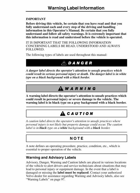
IMPORTANTBefore driving this vehicle, be certain that you have read and that you fully understand each and every step of the driving and handling information in this Operator's Manual. Be certain that you fully understand and follow all safety warnings. It is extremely important that this information is read and understood before the vehicle is operated.
IT IS IMPORTANT THAT THE FOLLOWING INFORMATION CONCERNING LABELS BE READ, UNDERSTOOD AND ALWAYS FOLLOWED.
The following types of labels are used throughout this manual:
A danger label directs the operator's attention to unsafe practices which could result in serious personal injury or death. The danger label is in white type on a black background with a black border.
A warning label directs the operator's attention to unsafe practices which could result in personal injury or severe damage to the vehicle. The warning label is in black type on a gray background with a black border.
A caution label directs the operator's attention to unsafe practices where personal injury is not likely but property damage could occur. The caution label is in black type on a white background with a black border.
A note defines an operating procedure, practice, condition, etc., which is essential to proper operation of the vehicle.
Warning and Advisory LabelsAdvisory, Danger, Warning and Caution labels are placed in various locations of the vehicle to alert drivers and service technicians about situations that may lead to personal injury or equipment damage. In the event that a label is damaged or missing the label must be replaced. Contact your authorized Volvo dealer for assistance regarding Warning and Advisory labels, also see “Warning Labels” on page 97.
General Information 1GENERAL INFORMATION
INFORMATION FOR THE OWNER
If there are questions on the maintenance and performance of your vehicle, please discuss them with your Volvo Truck dealer. Your authorized dealer is required to have trained mechanics, special tools and spare parts to fully service your vehicle. If necessary, your dealer will contact the manufacturer for any assistance.
In addition to this Operator's Manual, there may be additional instruction/operator's manuals supplied by component manufacturers. These manuals are placed in the Owner's Package and placed in the cab. Be sure to read all the manuals thoroughly before operating the vehicle.
Various safety labels may be placed about components by the component manufacturer. Be sure to read and follow these labels to prevent damage to the vehicle, personal injury or death.
Information in this manual refers to Volvo components and Volvo drivetrain. There is also certain information regarding the Cummins engine. For detailed information on the Cummins engine or non-Volvo engines and/or drivetrains contact the respective manufacturer.
Establish a Preventive Maintenance Program with the help of your local Volvo Truck dealer. A Preventive Maintenance Program makes it possible to maximize the amount of time your vehicle is up and running, resulting in longer component life. This makes for a safer vehicle by reducing any mechanical failures due to poor maintenance practices.
Various truck warranty coverage plans, contingent on application and weight class, are available. Please contact an authorized Volvo Truck Dealer for complete details. Replacement warranty certificates for Volvo Trucks are available from authorized Volvo dealers.
For trucks placed in service after October, 2002 and operating in the USA, Mexico and Canada, Volvo dealers can order copies of the Standard Truck Warranty Certificate and the Premium (Purchased) Truck Coverage Certificate. Warranty Certificate copies and Operator Manuals are available in either English, Spanish or French. Contact your authorized Volvo Truck dealer for more information.
2 General Information
Federal law requires manufacturers to notify owners of its products in the event of a non-compliance to a Federal Motor Vehicle Safety Standard or if a safety related defect is discovered. If you are not the original owner of this vehicle, please notify us about the change in ownership at the address below or through an authorized Volvo Truck dealer. This is the only way we will be able to contact you if necessary.
Volvo Trucks North America
Attn: Vehicle Registration Dept.
P.O. Box 26115
Greensboro, NC 27402–6115
United States of America
DO NOT Remove this Operator's manual from the vehicle, it contains important operational and safety information that is needed by all drivers and owners of this vehicle.
Illustrations in this manual are used for reference only and may differ slightly from the actual vehicle, however, key components addressed in the manual are represented as accurately as possible.
General Information 3
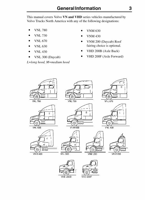
This manual covers Volvo VN and VHD series vehicles manufactured by Volvo Trucks North America with any of the following designations:
L=long hood, M=medium hood
� VNL 780
� VNL 730
� VNL 670
� VNL 630
� VNL 430
� VNL 300 (Daycab)
� VNM 630
� VNM 430
� VNM 200 (Daycab) Roof fairing choice is optional.
� VHD 200B (Axle Back)
� VHD 200F (Axle Forward)
4 General Information
This manual, and other literature for specific components, for example, Volvo Maintenance and Engine, Cummins engine, Eaton transmission, etc., contain important information which will assist you in safely operating this vehicle. They contain advice and instructions which will enable you to get the operating economy and performance that you expect from this quality vehicle.
All information, illustrations and specifications contained in this manual are based upon the latest product information available at the time of publication. If any questions arise concerning the current status of Federal or state laws, the appropriate Federal or state agency should be contacted.
Volvo Trucks North America reserves the right to make changes at any time or to change specifications or design without notice and without incurring obligation.
OPERATINGBefore driving this vehicle, locate the instruments and controls, and become thoroughly familiar with their operation. After starting and when driving, always check to make sure the instrument readings are normal.
Certain components on the vehicle are supplied by vendors who meet Volvo Truck's stringent quality requirements. In addition to major components, these quality requirements also apply to parts, which are expected to wear out over time and will need replacement. Examples are filters, tires, brakes, wiper blades, belts etc.
When replacing these components select parts that are equal to, or exceed the quality of the original equipment components. After the worn parts are replaced, there may be a difference in the way the vehicle operates or performs. For example, new tires may have different handling characteristics than old, worn tires. Be aware of possible changes in the way the vehicle functions and adapt your driving style accordingly.

General Information 5
GENERAL SAFETY INFORMATION
Operating the Vehicle
Never try to operate or work on this vehicle while under the influence of alcohol. Your reflexes can be affected by the smallest amount of alcohol. Drinking and operating this vehicle can lead to an accident, causing serious personal injury or death.
All items within the cab must be secured before the vehicle is set in motion. This includes, but is not limited to, drinks, clothes, books, televisions, etc. In the event of a collision, loose items could fly around inside the cab. This could cause personal injury.
Every vehicle, including heavy duty vehicles, have blind spots. The size of blind spots vary from driver to driver and from situation to situation. As a skilled, professional driver, you are in the best position to avoid accidents in turns, lane changes or other maneuvers. Volvo Trucks North America provides standard equipment (such as cabs, windshields, window sizes and mirrors), preferred by most owners and drivers under most conditions and in most applications.
However, due to differences in the size of drivers, their seating positions, the use and operation of their vehicles, personal preferences and other factors, no combination of mirrors and other visibility enhancement devices can eliminate all blind spots in every situation.
The safe operation of this vehicle is determined by the you, the driver. Because of your special preferences, needs and circumstances, you may choose to add extra mirrors and/or other visibility enhancement devices. If so, contact an authorized Volvo Truck dealer to obtain parts which best fit your personal needs and preferences.
6 General Information
Operating In Bobtail Mode
When operating bobtail, be certain that glad hands, trailer air hoses, electrical cable and connectors are properly stowed and secure. Do not allow them to rub or chafe on other components.
Depending on customer specification, some tractors may be equipped with a bobtail air brake proportioning valve which automatically redistributes the braking force between front and rear axles when not hooked up to a semitrailer (bobtail operation).
When operating in bobtail mode, the rear brake chambers receive reduced or proportional brake air pressure. When the tractor is towing a trailer, the rear brake chambers will receive full (normal) brake pressure. For tractors with no proportioning valve, the ABS system automatically controls brake pressure.
DO NOT Overload
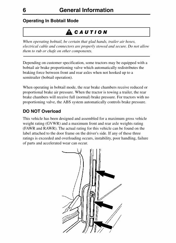
This vehicle has been designed and assembled for a maximum gross vehicle weight rating (GVWR) and a maximum front and rear axle weights rating (FAWR and RAWR). The actual rating for this vehicle can be found on the label attached to the door frame on the driver's side. If any of these three ratings is exceeded and overloading occurs, instability, poor handling, failure of parts and accelerated wear can occur.
General Information 7
Under no circumstances should the published GVWR, FAWR, and/or RAWR be exceeded. Failure to observe these precautions can lead to the loss of vehicle control, resulting in a vehicle accident causing serious personal injury or death.
DO NOT exceed the load rating of the tires or the vehicle weight ratings. Overloading may result in tire failure causing loss of vehicle control, leading to an accident resulting in severe personal injury or death.
Reporting Safety Defects
USA
The National Highway Traffic Safety Administration (NHTSA) and Volvo Trucks North America should be informed immediately if you believe that the vehicle has a defect that could cause a vehicle accident, injury or death.
Contact NHTSA by calling the Auto Safety Hotline, 1 (800) 424-9393 or 1 (888) 327-4236, or by writing to: NHTSA, U. S. Department of Transportation, Washington, DC 20590.
Canada
Refer customer complaints to Volvo Trucks Canada, Inc. or to Transport Canada, Defect Investigations and Recalls.
Canadian customers who wish to report a safety-related defect to Transport Canada, Defect Investigations and Recalls, may telephone the toll free hotline 1-800-333-0510, or contact Transport Canada by mail at: Transport Canada, ASFAD, Place de Ville Tower C, 330 Sparks Street, Ottawa ON K1A 0N5.
For additional road safety information, please visit the Road Safety website at: http://www.tc.gc.ca/roadsafety/menu.htm
1 (905) 795-1555
1 (800) 333-0510 (within Canada only)
8 General Information
Mexico
Volvo Trucks of Mexico, S.A. de C.V. should be informed immediately if you believe the vehicle has a defect that could cause a vehicle accident, injury or death. Contact Volvo Trucks de Mexico by calling 011-52-55-50-81-68-50 or by writing to: Volvo Trucks de Mexico, S.A. de C.V., Prol. Paseo de la Reforma 600, 1er. Piso — 121, Col. Santa Fe Peña Blanca, C.P. 01210, México, D.F.
01 (800) 90 94 900 (within Mexico only)
For Roadside assistance information see “Service Assistance and Manuals” on page 417.
VN FRONT BUMPER/LICENSE PLATE MOUNTING
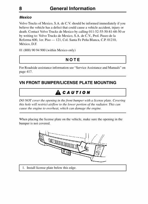
DO NOT cover the opening in the front bumper with a license plate. Covering this hole will restrict airflow to the lower portion of the radiator. This can cause the engine to overheat, which can damage the engine.
When placing the license plate on the vehicle, make sure the opening in the bumper is not covered.
1. Install license plate below this edge.

General Information 9
Multiple License Plate Mounting
Install multiple license plates as shown.
VORAD License Plate Mounting
Install multiple license plates as shown.
1. Install license plates below this edge.
1. Install license plates below this edge.
10 General Information
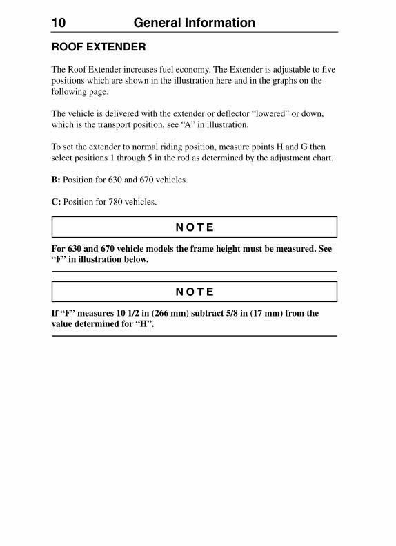
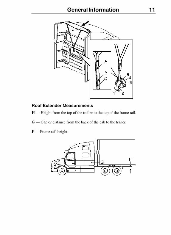
ROOF EXTENDER
The Roof Extender increases fuel economy. The Extender is adjustable to five positions which are shown in the illustration here and in the graphs on the following page.
The vehicle is delivered with the extender or deflector “lowered” or down, which is the transport position, see “A” in illustration.
To set the extender to normal riding position, measure points H and G then select positions 1 through 5 in the rod as determined by the adjustment chart.
B: Position for 630 and 670 vehicles.
C: Position for 780 vehicles.
For 630 and 670 vehicle models the frame height must be measured. See “F” in illustration below.
If “F” measures 10 1/2 in (266 mm) subtract 5/8 in (17 mm) from the value determined for “H”.
General Information 11
Roof Extender Measurements
H — Height from the top of the trailer to the top of the frame rail.
G — Gap or distance from the back of the cab to the trailer.
F — Frame rail height.
12 General Information
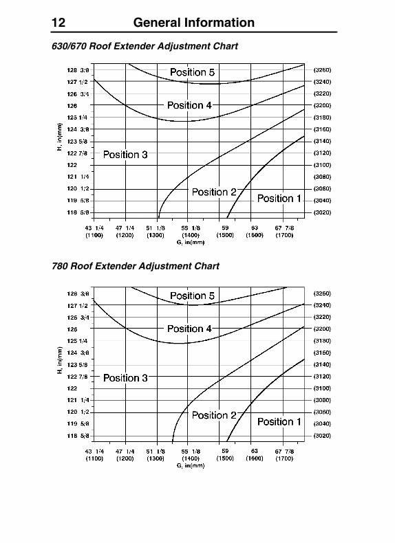
630/670 Roof Extender Adjustment Chart
780 Roof Extender Adjustment Chart
General Information 13
MODIFICATIONS TO VEHICLE
Chassis Frame
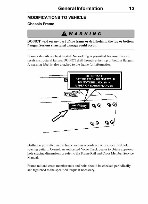
DO NOT weld on any part of the frame or drill holes in the top or bottom flanges. Serious structural damage could occur.
Frame side rails are heat treated. No welding is permitted because this can result in structural failure. DO NOT drill through either top or bottom flanges. A warning label is also attached to the frame for information.
Drilling is permitted in the frame web in accordance with a specified hole spacing pattern. Consult an authorized Volvo Truck dealer to obtain approved hole spacing dimensions or refer to the Frame Rail and Cross Member Service Manual.
Frame rail and cross member nuts and bolts should be checked periodically and tightened to the specified torque if necessary.

14 General Information
Frame Alterations
Under no circumstances can the frame be cut and an extension piece added to increase the wheelbase. The only alteration allowed is wheel base shortening, where the only change in the frame rail is a new hole pattern drilled for the new location of the rear suspension.
Welding In Vehicle
Use only electric welders due to the coating on material used to build cabs. Oxygen and Acetylene welding will not bond properly due to coating.
Do not weld anywhere in or on the vehicle before disconnecting batteries, all electronic control units (ECUs) and instrument cluster. See “Electrical System” on page 346. Refer to “Welding” on page 353.
DO NOT use oxy/acetylene welding to repair cab panels.
EXHAUST AND NOISE EMISSIONS
General
USA
The Federal Clean Air Act, Section 203 (a) (3), states the following concerning the removal of air pollution control devices or modification of a certified engine to a non-certified configuration:
“The following acts and the causing thereof are prohibited:
(3) For any person to remove or render inoperative any device or element of design installed on or in a motor vehicle or motor vehicle engine in compliance with regulations under this part prior to its sale and delivery to the ultimate purchaser, or for any manufacturer or dealer knowingly to remove or render inoperative any such design after sale and delivery to the ultimate purchaser.”
Specifically, please note that no person may make such changes prior to the sale and delivery of the vehicle to the ultimate purchaser, and, in addition, no manufacturer or dealer may take such action after sale and delivery of the vehicle to the ultimate purchaser. The law provides a penalty of up to $10, 000 for each violation.

General Information 15
Canada
The same conditions that apply in the USA apply to Canada, with one exception. After the vehicle is sold to a retail customer, that is, the end user, the jurisdiction controlling the emission control devices becomes the province in which the vehicle is licensed. No changes should be made that render any or all of the devices inoperative.
If the owner/operator wishes to make changes to the emission control devices, check with the provincial authority before changes are made.
Mexico
The same conditions that apply in the USA apply to Mexico. Refer to the Mexican Federal Law for Emission Control which adheres to EPA regulations. No changes should be made that render any or all of the emissions control devices inoperative.
If the owner/operator wishes to make changes to the emission control devices, check with the state authority before changes are made.
California and EPA Emission Control Warranty Statement
Your Warranty Rights and Obligations
The California Air Resources Board and Volvo Trucks North America (VTNA) are pleased to explain the emission control system warranty on your new vehicle. In California, new motor vehicles must be designed, built and equipped to meet the State's stringent anti-smog standards. Volvo Trucks North America must warrant the emission control system on your vehicle for the periods of time listed below provided there has been no abuse, neglect or improper maintenance of your vehicle.
Your emission control system may include parts such as fuel injection system, EGR and engine computer. Also included may be hoses, connectors and other emission-related assemblies.
Where a warrantable condition exists, Volvo Trucks North America will repair your vehicle at no cost to you including diagnosis, parts and labor.
EPA Emissions Performance Warranty
Your Warranty Rights and Obligations
The U.S. Environmental Protection Agency (EPA) and Volvo Trucks North America (VTNA) are pleased to explain the emissions performance warranty on your vehicle. In compliance with section 207(b) of the Clean Air Act,
16 General Information
VTNA must warrant the emission control system on your vehicle for the periods of time listed below, provided there has been no abuse, neglect or improper maintenance of your vehicle.
This manual contains maintenance information, including time and/or mileage intervals at which such maintenance should be performed.
For instructions on proper maintenance, including time and/or mileage intervals at which such maintenance should be performed, see your Volvo Maintenance and Engine Operator's Manual VN, VHD.
Your emission control system may include parts such as fuel injection system, engine computer, and exhaust after treatment devices (as applicable). Also included may be hoses, connectors or other emission-related assemblies.
Refer to the Warranty Certificate for complete coverage details.
Federal warranty provisions apply to all vehicles sold in all U.S. states and territories regardless of whether a state has enacted state warranty provisions that differ from the federal provisions.
Where a warrantable condition exists, VTNA will repair your vehicle at no cost to you (including diagnosis, parts and labor) any emission control device or system which causes a vehicle to fail an EPA-approved emission short test during its useful life, if you have maintained and operated the vehicle in accordance with the written instructions of VTNA.
If a facility at which the vehicle is initially presented for repair is unable for any reason to honor the claim, then, unless you waive in writing, the repair facility must forward the claim to VTNA warranty Administration, (336) 393-2000.
Manufacturer's Warranty Coverage
This warranty is applicable for a period of five years, 250,000 miles or 6,250 hours of operation, whichever first occurs. If an emission-related part of your vehicle is defective, the part will be repaired or replaced by Volvo Trucks North America.
This is your emission control system DEFECTSWARRANTY.
Owner's Warranty Responsibilities
As the vehicle owner, you are responsible for the performance of the required maintenance listed in your owner's manual. Volvo Truck North America (VTNA) recommends that you retain all receipts covering maintenance on your truck, but VTNA cannot deny warranty solely for the lack of receipts or for your failure to ensure the performance of all scheduled maintenance.
General Information 17
You are responsible for presenting your vehicle to a VTNA dealer as soon as a problem exists. The warranty repairs should be completed in a reasonable amount of time, not to exceed 30 days. Claim procedures are outlined in the "Volvo Service Operations Manual."
As the vehicle owner, you should also be aware that VTNA may deny you warranty coverage if your vehicle or a part has failed due to abuse, neglect, improper maintenance or unapproved modifications.
If you have any questions regarding your warranty rights and responsibilities, you should contact VTNA Warranty Administration, (336) 393-2000. For California vehicles, contact the California Air Resources Board at 9480 Telstar Avenue, El Monte, CA 91731.
Emission Control System Warranty
Volvo Trucks North America WARRANTS TO THE ORIGINAL OWNER, AND EACH SUBSEQUENT OWNER, OF A NEW TRUCK POWERED BY A VOLVO DIESEL ENGINE THAT THE EMISSION CONTROL SYSTEM OF YOUR TRUCK:
1. Is designed, built and equipped so as to conform at the time of sale to all regulations of the U.S. Environmental Protection Agency and the California Air Resources Board applicable at the time of the manufacture;
2. Is free from defects in material and workmanship which will cause the emission control components not to function as designed for a period of use of 5 years or 250,000 miles or 6,250 hours of engine operation, whichever comes first.
The 5 years/250,000 miles/6,250 hour warranty period shall begin on the date the vehicle is first delivered to the first retail purchaser or if the vehicle is placed in service as a demonstrator company vehicle prior to the sale at retail, on the date the vehicle is the first placed in service.
The emission control systems of your new VOLVO engines were designed, built and tested using genuine VOLVO parts, and the engine is certified as being in conformity with Federal and California emission control regulations. Accordingly, it is recommended that any replacement parts used for maintenance, repair or replacement of emission control systems by VOLVO parts.
The owner may elect to have maintenance, replacement or repair of the emission control components and systems performed by any vehicle repair establishment or individual and may elect to use parts other than VOLVO parts for such maintenance replacement or repair without invalidating this warranty;
18 General Information
the cost of such services or parts, however, will not be covered under the warranty except in an emergency situation. A part not being available or a repair not being completed within 30 days also constitutes an emergency.
Use of replacement parts which are not of equivalent quality may impair the effectiveness of emission control systems. If other than Volvo parts are used for maintenance, owner should obtain assurances that such parts are warranted by their manufacturer to be equivalent to genuine VOLVO parts. However, the use of other than Volvo replacement parts does not invalidate the warranty on other components, unless such parts cause damage to warranted parts.
Repairs and service covered by the warranty will be performed by an authorized Volvo Trucks North America dealer at their place of business with no charge for parts or labor including diagnosis using VOLVO parts for the emission control system, that requires replacement and is covered by the warranty and found defective.
In case of an emergency, where an authorized Volvo Trucks North America dealer is not available, repairs may be performed at any available service establishment or by the owner, using any equivalent replacement parts and Volvo Trucks North America will reimburse the owner for such repairs including diagnosis not to exceed Volvo Trucks North America's suggested retail price for the warranted parts and the labor rate appropriate for the geographical area and the tasks performed.
Replaced parts and paid invoices must be presented to a Volvo Trucks North America dealer for reimbursement.
The emissions control parts covered by this Emission Control System Warranty are listed under "What Is Covered by the Emissions Warranty." You are responsible for the performance of all required maintenance on your new VOLVO engine, including maintenance or repairs needed due to severe operating conditions. Volvo Trucks North America will not deny a warranty claim solely because you have no record of maintenance. However, Volvo Trucks North America may deny a warranty claim if your failure to perform required maintenance resulted in the failure of a warranted part. Receipts covering the performance of regular maintenance should be retained in the event questions arise concerning maintenance. The receipts should be transferred to each subsequent owner of the vehicle with the emission warranted engine.
If the warranty claim is denied, VTNA shall provide a written basis for denial within 30 days or a shorter time if required by local, state or federal law. Failure to provide written basis for denial within 30 days or shorter time limit

General Information 19
required by state, local or federal law or for reasons not attributable to the vehicle owner or events beyond the control of VTNA shall result in VTNA being responsible for repairing the vehicle free of charge to the vehicle owner.
Customer Assistance
Volvo Trucks North America wishes to help to assure that the Emission Control System Warranty is properly administered. In the event that you do not receive the warranty service to which you believe you are entitled under the Emission Control System Warranty, you should contact Volvo Trucks North America Warranty Administration, (336) 393-2000. If you need additional assistance or information concerning the Emission Control System Warranty, contact: Volvo Trucks North America, Warranty Administration, (336) 393-2000.
You can obtain further warranty information or report violations of the terms of Emissions Performance Warranty by contacting the Manager, Certification and Compliance Division (6405J), Warranty Claims, Environmental Protection Agency, Ariel Rios Building, 1200 Pennsylvania Ave. N.W., Washington, D.C. 20460.
What Is Not Covered by the Emission Warranty
This warranty does not cover:
1. Malfunctions in any part caused by any of the following: misuse, abuse, improper adjustments unless performed by a Volvo Trucks North America dealer, modifications, alterations, tampering, disconnection, improper or inadequate maintenance, or use of fuels not recommended for the engine as described in the owner's manual.
2. Damage resulting from accident, acts of nature or other events beyond the control of Volvo Trucks North America.
3. The replacement of expendable maintenance items such as filters, hoses, belts, oil, thermostat and coolant made in connection with scheduled maintenance services once these parts have been replaced. Any parts replaced under warranty before the first required replacement point are warranted for the remainder of the warranty period.
4. Replacement items which are not genuine Volvo parts or not authorized by Volvo Trucks North America.
5. Loss of time, inconvenience, loss of use of vehicle engine, or commercial loss.
20 General Information
6. Any vehicle on which the odometer or hourmeter has been disconnected or the mileage (or hours) has been altered so the actual usage cannot be readily be determined.
7. Any vehicle registered and normally operated outside the United States.
What is Covered by the Emission Warranty
The following is a list of the items that are considered a part of the Emission Control Systems and are covered by the Emission Warranty when installed as original equipment by Volvo Trucks North America on vehicles which were built to conform to Environmental Protection Agency and California Air Resources Board regulations
IMPORTANT - This may not include expendable maintenance items. Emission related parts requiring scheduled maintenance are warranted until their first scheduled replacement point.
I. Fuel Injection System
A. Unit Injector
II. Air Induction System
A. Intake Manifold
B. Turbocharger System
C. Charge Air Cooler (Intercooler)
III. Exhaust System
A. Manifold
B. Exhaust After Treatment (catalyst) (if so equipped)
IV. Exhaust Gas Recirculation (EGR) System
A. EGR Valve Assemblies (including EGR function control)
B. EGR Pulse Reflector
C. EGR Valve Sensor
D. EGR Cooler with reed valves
E. Exhaust Pressure Governor
General Information 21
V. Engine Emission Control system
A. Ambient Air Temperature Sensor
B. Electronic Control Unit (including Barometric Absolute Pressure Sensor)
C. Engine Coolant Temperature Sensor
D. Boost Pressure/Charge Air Temperature Sensor
E. Camshaft Position Sensor
F. Speed Sensor, Fly Wheel
G. EGR Temperature Sensor
VI. Miscellaneous Items Used in Above Systems
A. Hose, clamps, fittings and tubing
B. Gaskets and seals
C. Wires, harnesses and connectors
THIS EMISSIONS PERFORMANCE WARRANTY STATEMENT IN NO WAY REPLACES, MODIFIES, ALTERS OR SUPERSEDES THE TRUCK WARRANTY CERTIFICATE, ITS TERMS AND CONDITIONS, AND ITS LIMITATIONS AND EXCLUSIONS.
BE CERTAIN YOU READ AND UNDERSTAND ALL WARRANTIES WHICH ACCOMPANIED YOUR VEHICLE.
Warranty coverage is subject to change without notice. Contact your authorized Volvo Truck dealer for the current warranty statement.
Noise Emissions
Volvo Trucks North America warrants to the first person who purchases this vehicle for purposes other than resale and to each subsequent purchaser, that this vehicle as manufactured by Volvo Trucks North America was designed, built and equipped to conform, at the time it left the control of Volvo Trucks North America, with all applicable U.S. EPA Noise Control Regulations.
This warranty covers this vehicle as designed, built and equipped by Volvo Trucks North America, and is not limited to any particular part, component or system of the vehicle manufactured by Volvo Trucks North America. Defects
22 General Information
in design, assembly or in any part, component or system of the vehicle as manufactured by Volvo Trucks North America, which, at the time it left the control of Volvo Trucks North America caused noise emissions to exceed Federal standards, are covered by this warranty for the life of the vehicle.
Noise Control System, Operator Inspection and Maintenance Requirements
Before inspecting a vehicle, set the parking brakes, place the transmission in neutral, and block the wheels. Failure to do so can result in unexpected vehicle movement and can cause serious personal injury or death.
A Noise Control System Maintenance Log is located in “Noise Control Log” on page 26. This log should be used to document all Noise Control System related maintenance, whether the maintenance results from a specific noise control system inspection, or a deficiency identified during another general maintenance event.
If additional log space is needed, further entries may be added on a separate sheet of paper. Store these additions with the main log to preserve a comprehensive record. It is recommended that copies of all noise emissions related maintenance invoices be retained.
The following Noise Control System inspection and maintenance instructions contain suggested maintenance intervals. These intervals may need adjustment in order to best accommodate the specific vehicle usage. The following instructions only concern Noise Emissions related items and do not address or modify any general vehicle maintenance requirements.
Tampering with Noise Control System
Federal law prohibits the following acts or the causing thereof:
(1) The removal or rendering inoperative by any person, other than for purposes of maintenance, repair, or replacement, of any device or element of design incorporated into any new vehicle for the purpose of noise control prior to its sale or delivery to the ultimate purchaser or while it is in use;
or
(2) the use of the vehicle after such device or element of design has been removed or rendered inoperative by any person.
General Information 23
Among the acts that constitute tampering are the acts listed:
� Noise Shielding and Insulation Devices
� Cooling System
� Exhaust System
� Air Intake/Air Induction System
� Engine Control, EGR and Fuel Systems
Noise Shielding and Insulation Devices
Make sure sound shielding and insulating devices are intact. Inspect components for damage. Primary system components requiring noise related inspection include the hood, engine compartment insulating materials (including hood insulation, bulkhead insulation, doghouse insulation, etc.) splash shields, cab skirts, fender shields, and body panels. Inspect all related fasteners, brackets, and clamps for damage and tightness.
Acts that constitute tampering with the Noise Shielding and Insulations Devices:
Removing or rendering inoperative the engine and/or transmission noise deadening panels, shields or insulating materials.
Removing or rendering inoperative the cab-tunnel or hood noise insulating materials.
Removing or rendering inoperative any truck body mounted sound insulation components and/or shields (cab or fender shields, skirts, wheel housing splash shields, etc.).
24 General Information
Cooling System
DO NOT work near the fan with the engine running or the ignition in the ON position. The engine fan can engage at any time without warning. Anyone near the fan when it turns on could be seriously injured.
Visually inspect cooling system components for damage, and/or misalignment.
Primary system components requiring noise related inspection include fan blades, fan clutch, fan shroud, fan ring, and recirculation shields. Check fan blades, fan ring, fan shroud, and recirculation shields for any damage. Verify that fan blades clear the fan ring. Inspect all related fasteners, brackets, and clamps for damage and tightness. Confirm operation of temperature modulated fan clutch.
Acts that constitute tampering with the Cooling System:
Removing or rendering inoperative cooling system components (such as the temperature modulated fan clutch, fan shroud, fan ring, recirculation shields, etc.).
Exhaust System
Make sure the exhaust system is intact. Inspect for damage, misalignment and/or leakage. Primary system components requiring noise related inspection include muffler body, exhaust manifold, turbocharger, and all exhaust system (rigid and flexible) piping. Closely check the system for exhaust leaks. Special attention should be given to all welds, seams, gaskets, support points, clamps, couplings and connections.
Inspect all exhaust system fasteners, brackets, and clamps for damage and tightness. Check integrity of internal muffler baffling by revving the engine through normal operating speeds. Excessive rattling sounds or very loud operation indicates a failure within the muffler.
Acts that constitute tampering with the Exhaust System:
Removing or rendering inoperative exhaust system components (such as the muffler, pipes, clamps, etc.).
General Information 25
Hot engine! Keep yourself clear of all moving parts or hot engine parts, exhaust gases, and/or fluids. A hot engine, exhaust, and/or fluids can cause burns.
Air Intake/Air Induction System
Make sure the air intake system is intact. Inspect components for damage, misalignment and/or leakage. Primary system components requiring noise related inspection include the air cleaner housing, air cleaner element, turbocharger, charge air cooler and intake manifold.
Also inspect all ducts, pipes, hoses, tubing and elbows used to interconnect the system. Special attention should be given to all welds, seams, gaskets, support points, clamps, couplings and connections.
Inspect all intake system fasteners, brackets, and clamps for damage and tightness.
Acts that constitute tampering with the Air Intake/Air Induction System:
Removing or rendering inoperative air intake/induction system components (filter, filter housings, ducts, etc.).
Engine Control, EGR and Fuel Systems
Acts that constitute tampering with the Engine Control, EGR and Fuel Systems:
Removing rendering inoperative, or modifying the engine control system such as the ECU, EGR system components or the fuel system components, in order to allow the engine to operate outside of the manufacturer's specifications is not allowed and violates both warranty and legislation.

26 General Information
Noise Control Log
NOISE CONTROL SYSTEM MAINTENANCE LOG
DATE MILEAGE MAINTENANCE
PERFORMEDMAINTENANCE
FACILITY
General Information 27
VEHICLE DATA
Identification and Labels
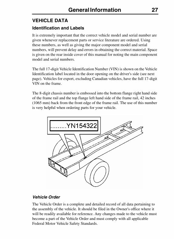
It is extremely important that the correct vehicle model and serial number are given whenever replacement parts or service literature are ordered. Using these numbers, as well as giving the major component model and serial numbers, will prevent delay and errors in obtaining the correct material. Space is given on the rear inside cover of this manual for noting the main component model and serial numbers.
The full 17-digit Vehicle Identification Number (VIN) is shown on the Vehicle Identification label located in the door opening on the driver's side (see next page). Vehicles for export, excluding Canadian vehicles, have the full 17-digit VIN on the frame.
The 8-digit chassis number is embossed into the bottom flange right hand side of the frame rail and the top flange left hand side of the frame rail, 42 inches (1065 mm) back from the front edge of the frame rail. The use of this number is very helpful when ordering parts for your vehicle.
Vehicle Order
The Vehicle Order is a complete and detailed record of all data pertaining to the assembly of the vehicle. It should be filed in the Owner's office where it will be readily available for reference. Any changes made to the vehicle must become a part of the Vehicle Order and must comply with all applicable Federal Motor Vehicle Safety Standards.
28 General Information
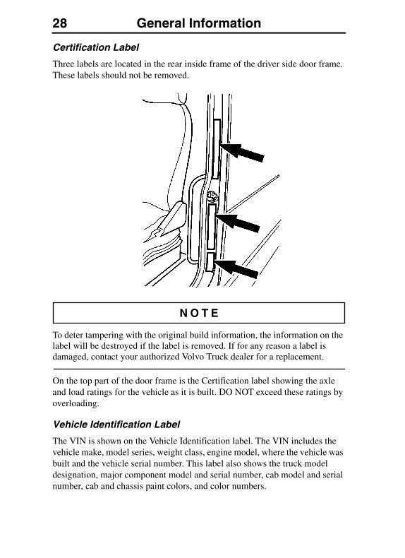
Certification Label
Three labels are located in the rear inside frame of the driver side door frame. These labels should not be removed.
To deter tampering with the original build information, the information on the label will be destroyed if the label is removed. If for any reason a label is damaged, contact your authorized Volvo Truck dealer for a replacement.
On the top part of the door frame is the Certification label showing the axle and load ratings for the vehicle as it is built. DO NOT exceed these ratings by overloading.
Vehicle Identification Label
The VIN is shown on the Vehicle Identification label. The VIN includes the vehicle make, model series, weight class, engine model, where the vehicle was built and the vehicle serial number. This label also shows the truck model designation, major component model and serial number, cab model and serial number, cab and chassis paint colors, and color numbers.
General Information 29
Noise Emission Control Label
The Noise Emission Control label is located at the bottom of the three labels on the rear inside frame of the driver side door. It is the Owner's responsibility to maintain the vehicle so that it conforms to EPA regulations.
Refer to “Tampering with Noise Control System” on page 22 for a listing of what constitutes tampering with the Noise Emissions Control.
Components
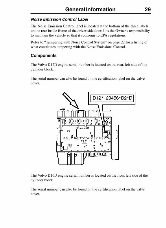
The Volvo D12D engine serial number is located on the rear, left side of the cylinder block.
The serial number can also be found on the certification label on the valve cover.
The Volvo D16D engine serial number is located on the front left side of the cylinder block.
The serial number can also be found on the certification label on the valve cover.
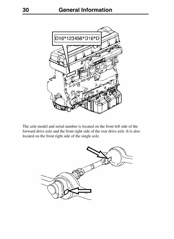
30 General Information
The axle model and serial number is located on the front left side of the forward drive axle and the front right side of the rear drive axle. It is also located on the front right side of the single axle.
Vehicle Access 31VEHICLE ACCESS
CAB DOORS AND DOOR LOCK
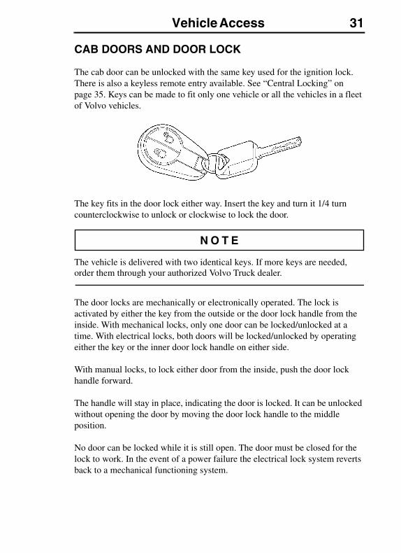
The cab door can be unlocked with the same key used for the ignition lock. There is also a keyless remote entry available. See “Central Locking” on page 35. Keys can be made to fit only one vehicle or all the vehicles in a fleet of Volvo vehicles.
The key fits in the door lock either way. Insert the key and turn it 1/4 turn counterclockwise to unlock or clockwise to lock the door.
The vehicle is delivered with two identical keys. If more keys are needed, order them through your authorized Volvo Truck dealer.
The door locks are mechanically or electronically operated. The lock is activated by either the key from the outside or the door lock handle from the inside. With mechanical locks, only one door can be locked/unlocked at a time. With electrical locks, both doors will be locked/unlocked by operating either the key or the inner door lock handle on either side.
With manual locks, to lock either door from the inside, push the door lock handle forward.
The handle will stay in place, indicating the door is locked. It can be unlocked without opening the door by moving the door lock handle to the middle position.
No door can be locked while it is still open. The door must be closed for the lock to work. In the event of a power failure the electrical lock system reverts back to a mechanical functioning system.
32 Vehicle Access
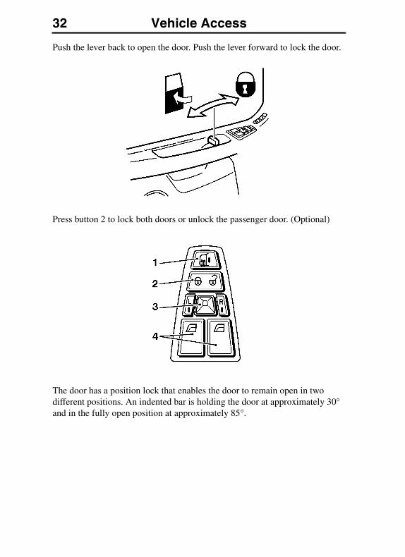
Push the lever back to open the door. Push the lever forward to lock the door.
Press button 2 to lock both doors or unlock the passenger door. (Optional)
The door has a position lock that enables the door to remain open in two different positions. An indented bar is holding the door at approximately 30° and in the fully open position at approximately 85°.
Vehicle Access 33
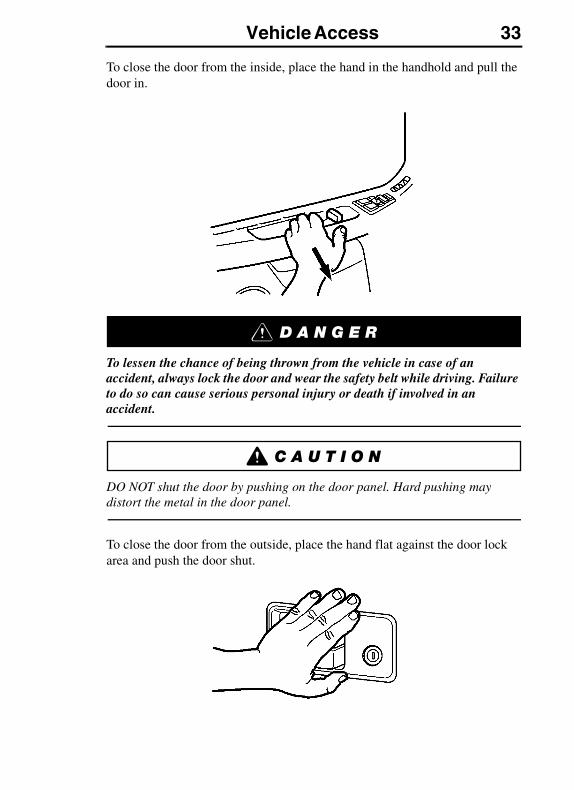
To close the door from the inside, place the hand in the handhold and pull the door in.
To lessen the chance of being thrown from the vehicle in case of an accident, always lock the door and wear the safety belt while driving. Failure to do so can cause serious personal injury or death if involved in an accident.
DO NOT shut the door by pushing on the door panel. Hard pushing may distort the metal in the door panel.
To close the door from the outside, place the hand flat against the door lock area and push the door shut.
34 Vehicle Access
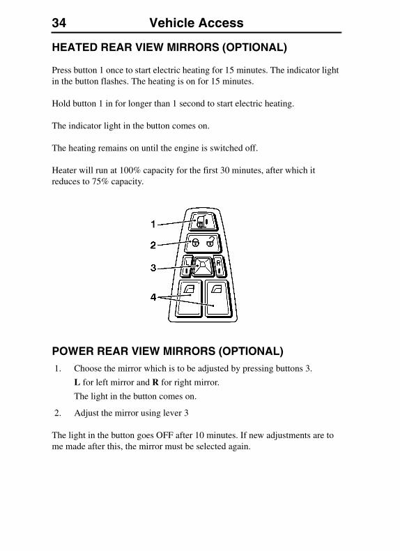
HEATED REAR VIEW MIRRORS (OPTIONAL)
Press button 1 once to start electric heating for 15 minutes. The indicator light in the button flashes. The heating is on for 15 minutes.
Hold button 1 in for longer than 1 second to start electric heating.
The indicator light in the button comes on.
The heating remains on until the engine is switched off.
Heater will run at 100% capacity for the first 30 minutes, after which it reduces to 75% capacity.
POWER REAR VIEW MIRRORS (OPTIONAL)1. Choose the mirror which is to be adjusted by pressing buttons 3.
L for left mirror and R for right mirror.
The light in the button comes on.
2. Adjust the mirror using lever 3
The light in the button goes OFF after 10 minutes. If new adjustments are to me made after this, the mirror must be selected again.
Vehicle Access 35
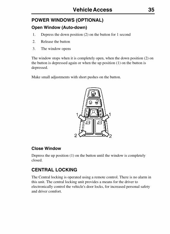
POWER WINDOWS (OPTIONAL)
Open Window (Auto-down)
1. Depress the down position (2) on the button for 1 second
2. Release the button
3. The window opens
The window stops when it is completely open, when the down position (2) on the button is depressed again or when the up position (1) on the button is depressed.
Make small adjustments with short pushes on the button.
Close Window
Depress the up position (1) on the button until the window is completely closed.
CENTRAL LOCKINGThe Central locking is operated using a remote control. There is no alarm in this unit. The central locking unit provides a means for the driver to electronically control the vehicle's door locks, for increased personal safety and driver comfort.

36 Vehicle Access
Unlock Door using Remote Control
Unlock the driver door
Press UNLOCK
The side indicators flash
To unlock the passenger door
1. Unlock the driver's door using UNLOCK
The side indicators flash
2. Press UNLOCK again
The side indicators flash
Vehicle Access 37
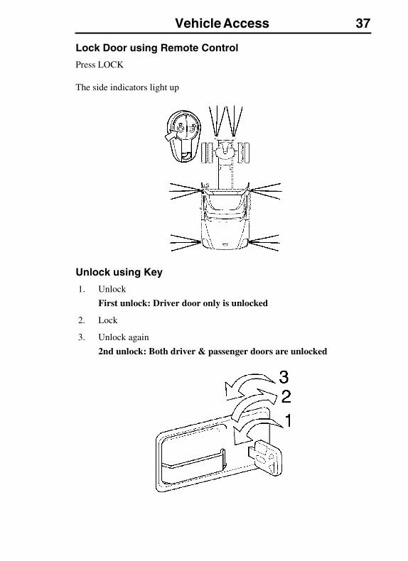
Lock Door using Remote Control
Press LOCK
The side indicators light up
Unlock using Key
1. Unlock
First unlock: Driver door only is unlocked
2. Lock
3. Unlock again
2nd unlock: Both driver & passenger doors are unlocked
38 Vehicle Access
CAB ENTRY AND EXIT
General
DO NOT stand on the steps or any other part of the vehicle while it is in motion. The steps and the back of cab access deck plates are only for entering/exiting the vehicle and not for riding on. Failure to heed this warning can result in serious personal injury or death.
Steps are designed to be slip resistant and to provide a stable surface for entering or exiting the cab. However, accumulation of ice, dirt, lubricants, etc. on the steps can make entering or exiting hazardous. Always make sure the steps are free from slippery substances. Failure to follow this guideline may result in a fall that can cause serious personal injury or death.
To avoid personal injury due to a slip and/or fall, observe all the guidelines explained in this section.
Wearing shoes with soles that are dirty or wet increases the chance of injury from slipping and falling. Be careful when entering the cab with dirty or wet soles.
Both the operator and passenger should exercise caution when entering or exiting the cab. Use the steps and grab handles to safely get in and out of the cab.
Vehicle Access 39
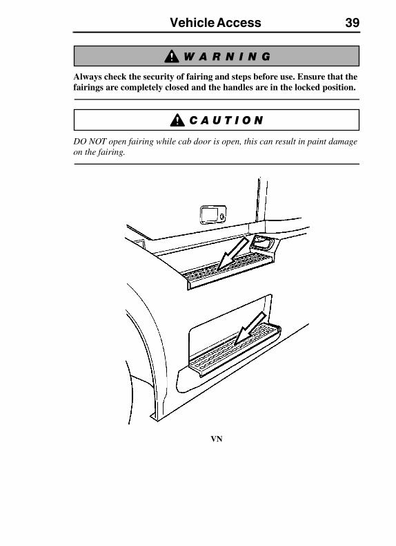
Always check the security of fairing and steps before use. Ensure that the fairings are completely closed and the handles are in the locked position.
DO NOT open fairing while cab door is open, this can result in paint damage on the fairing.
VN
40 Vehicle Access
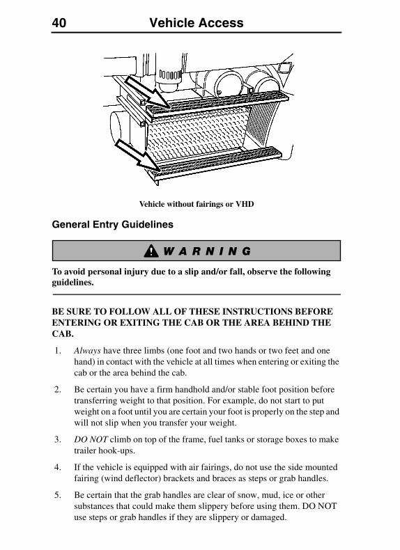
Vehicle without fairings or VHD
General Entry Guidelines
To avoid personal injury due to a slip and/or fall, observe the following guidelines.
BE SURE TO FOLLOW ALL OF THESE INSTRUCTIONS BEFORE ENTERING OR EXITING THE CAB OR THE AREA BEHIND THE CAB.
1. Always have three limbs (one foot and two hands or two feet and one hand) in contact with the vehicle at all times when entering or exiting the cab or the area behind the cab.
2. Be certain you have a firm handhold and/or stable foot position before transferring weight to that position. For example, do not start to put weight on a foot until you are certain your foot is properly on the step and will not slip when you transfer your weight.
3. DO NOT climb on top of the frame, fuel tanks or storage boxes to make trailer hook-ups.
4. If the vehicle is equipped with air fairings, do not use the side mounted fairing (wind deflector) brackets and braces as steps or grab handles.
5. Be certain that the grab handles are clear of snow, mud, ice or other substances that could make them slippery before using them. DO NOT use steps or grab handles if they are slippery or damaged.
Vehicle Access 41
6. Be certain that all grab handles, steps and related parts are in good working condition. Any defects should be reported and repaired before using the grab handles and steps.
7. DO NOT step on the curved surface of the fuel tanks. They may be slippery from snow, mud, ice, water, spilled fuel or other slippery substances.
8. If a step is mounted to the top of the battery box, be certain that the battery box cover is properly fastened before stepping.
9. If a vehicle is equipped with removable chassis fairings, be certain the fairing is properly fastened before using steps. For more information on securing the fairings see “Chassis Fairing/Steps Open and Locked Positions” on page 46.
10. DO NOT jump from the cab or from the steps to the ground.
11. Always face the cab when entering or exiting.
12. DO NOT hold anything in your hands when entering or exiting the cab or the area behind the cab. Log books, cups, clipboards, jackets, luggage and the like can be placed on the cab floor or rear deck plate before entering or exiting.
13. Make sure your safety belt is disconnected before exiting the cab.
14. Make sure the safety belt is fully retracted and out of the way prior to entering or exiting the cab.
15. DO NOT put your foot on any surface that does not have slip resistant, self- cleaning material. If there is no step material, the surface may be slippery and you may fall.
16. Before entering or exiting, be certain that the soles of your shoes/boots are free from grease, mud or any other substance which could make them slippery.
17. Always put the foot flat on the top of the step. DO NOT place your foot on the side or edge of the step.
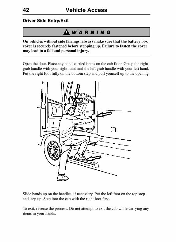
42 Vehicle Access
Driver Side Entry/Exit
On vehicles without side fairings, always make sure that the battery box cover is securely fastened before stepping up. Failure to fasten the cover may lead to a fall and personal injury.
Open the door. Place any hand-carried items on the cab floor. Grasp the right grab handle with your right hand and the left grab handle with your left hand. Put the right foot fully on the bottom step and pull yourself up to the opening.
Slide hands up on the handles, if necessary. Put the left foot on the top step and step up. Step into the cab with the right foot first.
To exit, reverse the process. Do not attempt to exit the cab while carrying any items in your hands.
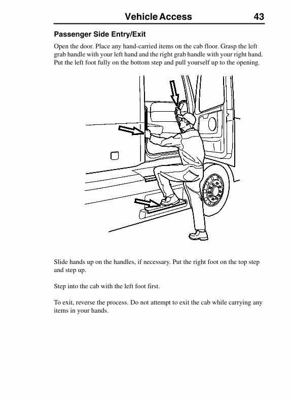
Vehicle Access 43
Passenger Side Entry/Exit
Open the door. Place any hand-carried items on the cab floor. Grasp the left grab handle with your left hand and the right grab handle with your right hand. Put the left foot fully on the bottom step and pull yourself up to the opening.
Slide hands up on the handles, if necessary. Put the right foot on the top step and step up.
Step into the cab with the left foot first.
To exit, reverse the process. Do not attempt to exit the cab while carrying any items in your hands.
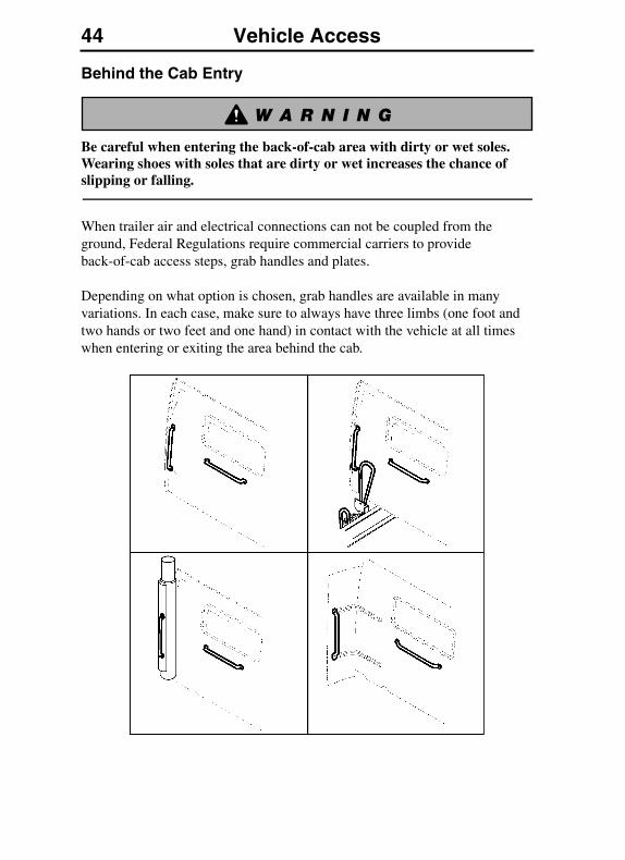
44 Vehicle Access
Behind the Cab Entry
Be careful when entering the back-of-cab area with dirty or wet soles. Wearing shoes with soles that are dirty or wet increases the chance of slipping or falling.
When trailer air and electrical connections can not be coupled from the ground, Federal Regulations require commercial carriers to provide back-of-cab access steps, grab handles and plates.
Depending on what option is chosen, grab handles are available in many variations. In each case, make sure to always have three limbs (one foot and two hands or two feet and one hand) in contact with the vehicle at all times when entering or exiting the area behind the cab.
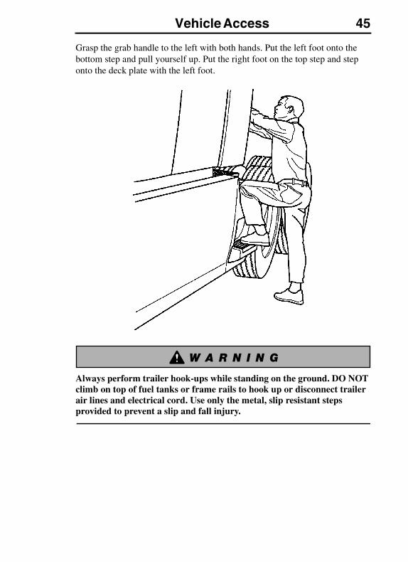
Vehicle Access 45
Grasp the grab handle to the left with both hands. Put the left foot onto the bottom step and pull yourself up. Put the right foot on the top step and step onto the deck plate with the left foot.
Always perform trailer hook-ups while standing on the ground. DO NOT climb on top of fuel tanks or frame rails to hook up or disconnect trailer air lines and electrical cord. Use only the metal, slip resistant steps provided to prevent a slip and fall injury.
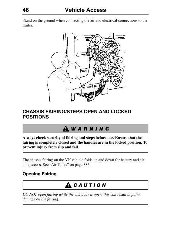
46 Vehicle Access
Stand on the ground when connecting the air and electrical connections to the trailer.
CHASSIS FAIRING/STEPS OPEN AND LOCKED POSITIONS
Always check security of fairing and steps before use. Ensure that the fairing is completely closed and the handles are in the locked position. To prevent injury from slip and fall.
The chassis fairing on the VN vehicle folds up and down for battery and air tank access. See “Air Tanks” on page 335.
Opening Fairing
DO NOT open fairing while the cab door is open, this can result in paint damage on the fairing.
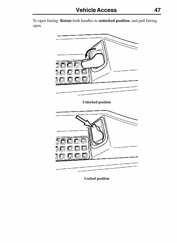
Vehicle Access 47
To open fairing: Rotate both handles to unlocked position, and pull fairing open.
Unlocked position
Locked position
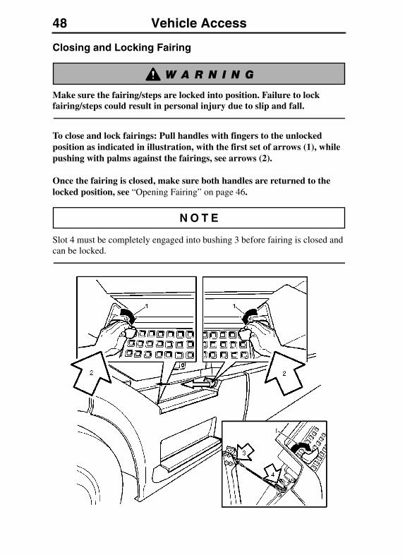
48 Vehicle Access
Closing and Locking Fairing
Make sure the fairing/steps are locked into position. Failure to lock fairing/steps could result in personal injury due to slip and fall.
To close and lock fairings: Pull handles with fingers to the unlocked position as indicated in illustration, with the first set of arrows (1), while pushing with palms against the fairings, see arrows (2).
Once the fairing is closed, make sure both handles are returned to the locked position, see “Opening Fairing” on page 46.
Slot 4 must be completely engaged into bushing 3 before fairing is closed and can be locked.
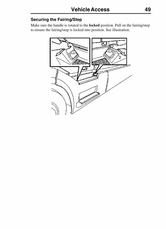
Vehicle Access 49
Securing the Fairing/StepMake sure the handle is rotated to the locked position. Pull on the fairing/step to ensure the fairing/step is locked into position. See illustration.
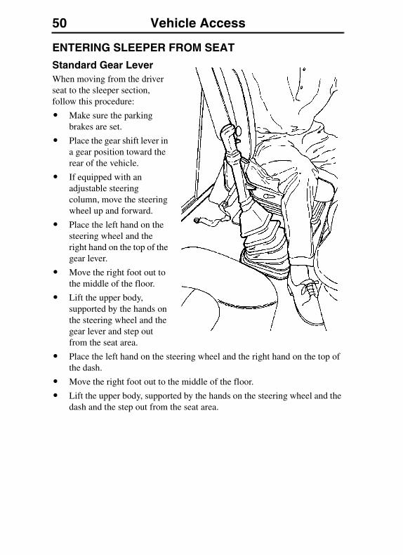
50 Vehicle Access
ENTERING SLEEPER FROM SEAT
Standard Gear LeverWhen moving from the driver seat to the sleeper section, follow this procedure:
� Make sure the parking brakes are set.
� Place the gear shift lever in a gear position toward the rear of the vehicle.
� If equipped with an adjustable steering column, move the steering wheel up and forward.
� Place the left hand on the steering wheel and the right hand on the top of the gear lever.
� Move the right foot out to the middle of the floor.
� Lift the upper body, supported by the hands on the steering wheel and the gear lever and step out from the seat area.
� Place the left hand on the steering wheel and the right hand on the top of the dash.
� Move the right foot out to the middle of the floor.
� Lift the upper body, supported by the hands on the steering wheel and the dash and the step out from the seat area.

Vehicle Access 51
LUGGAGE COMPARTMENT VN
Always place heavy objects in the luggage compartment. Sudden stops or sudden turns could cause personal injury if heavy objects fall from overhead storage shelves.
To gain access to the luggage compartments, there is a pull-ring connected to the lock, located at the lower rear corner of the cab door opening, on each side (not shown). Pull ring to unlock the door. The lock has a safety latch that will hold the door in place, even if the door is not fully locked. To open door, hold pull-ring out while pulling the door out.
The door swings out from the bottom on hinges mounted on the top. To assist in opening and to hold the door open, there are two compressed gas cylinders mounted on each door. The door will swing up by itself when pulled out a short distance and then released. Manually switch the luggage lamp ON. Switch lamp OFF before closing door.
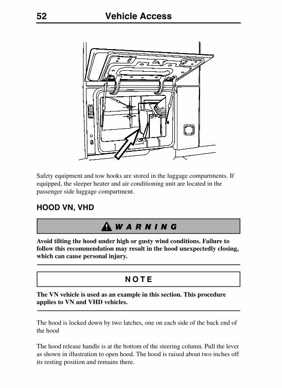
52 Vehicle Access
Safety equipment and tow hooks are stored in the luggage compartments. If equipped, the sleeper heater and air conditioning unit are located in the passenger side luggage compartment.
HOOD VN, VHD
Avoid tilting the hood under high or gusty wind conditions. Failure to follow this recommendation may result in the hood unexpectedly closing, which can cause personal injury.
The VN vehicle is used as an example in this section. This procedure applies to VN and VHD vehicles.
The hood is locked down by two latches, one on each side of the back end of the hood
The hood release handle is at the bottom of the steering column. Pull the lever as shown in illustration to open hood. The hood is raised about two inches off its resting position and remains there.
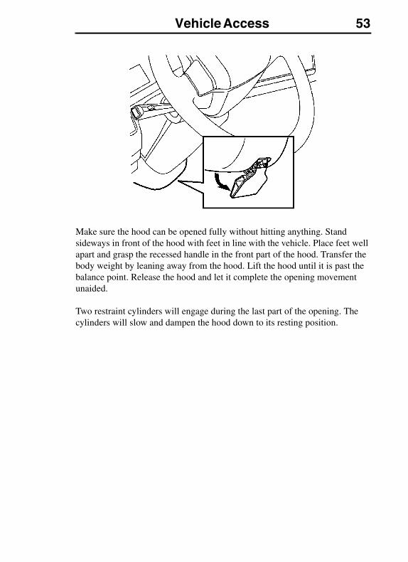
Vehicle Access 53
Make sure the hood can be opened fully without hitting anything. Stand sideways in front of the hood with feet in line with the vehicle. Place feet well apart and grasp the recessed handle in the front part of the hood. Transfer the body weight by leaning away from the hood. Lift the hood until it is past the balance point. Release the hood and let it complete the opening movement unaided.
Two restraint cylinders will engage during the last part of the opening. The cylinders will slow and dampen the hood down to its resting position.
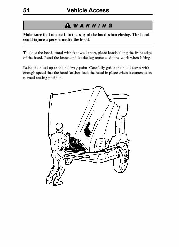
54 Vehicle Access
Make sure that no one is in the way of the hood when closing. The hood could injure a person under the hood.
To close the hood, stand with feet well apart, place hands along the front edge of the hood. Bend the knees and let the leg muscles do the work when lifting.
Raise the hood up to the halfway point. Carefully guide the hood down with enough speed that the hood latches lock the hood in place when it comes to its normal resting position.
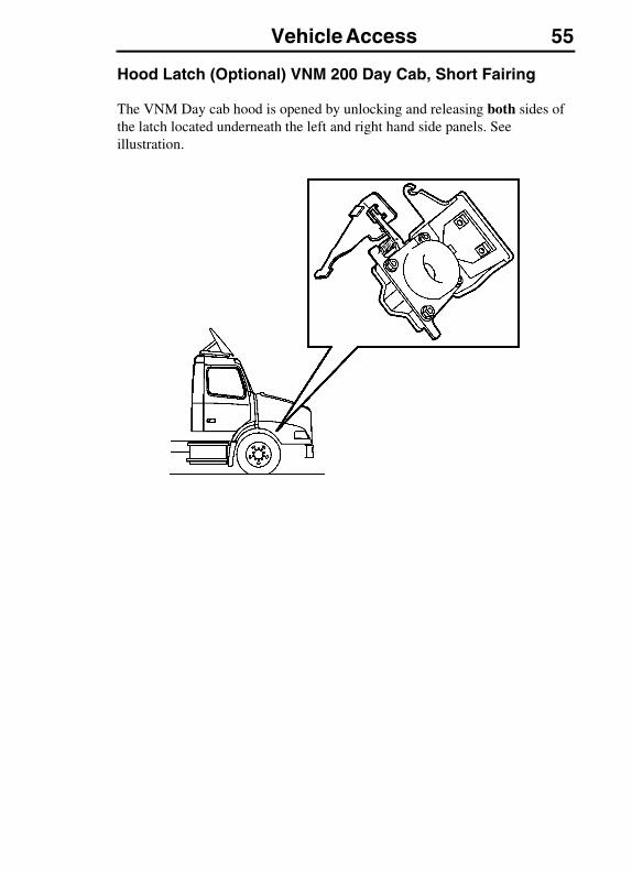
Vehicle Access 55
Hood Latch (Optional) VNM 200 Day Cab, Short Fairing
The VNM Day cab hood is opened by unlocking and releasing both sides of the latch located underneath the left and right hand side panels. See illustration.

56 Pre-Trip Inspection and Daily MaintenancePRE-TRIP INSPECTION AND DAILY MAINTENANCE
GENERAL
Before working on or inspecting a vehicle, set the parking brakes, place the transmission in neutral and block the wheels. Failure to do so can result in unexpected vehicle movement and can cause serious personal injury or death.
Safety is the most important and obvious reason for doing a pre-trip inspection. Federal and state laws require inspection performed by the driver. Federal and state inspectors also inspect commercial vehicles. An unsafe vehicle can be placed “out of service” until the driver or owner corrects the deficiency. Owners and operators should familiarize themselves with sections 49 CFR 396.11 and 396.13 concerning Federal requirements for vehicle inspection. Certain other laws may also apply.
Section 49 CFR 396.13 states that all motor carrier drivers must complete a written report at the end of each work day for each vehicle operated, covering most of what is covered in the pre-trip list. The report should list all defects or deficiencies discovered by the driver. A pre-trip inspection prepares for the end-of-work report.
Starting on the next page are suggested guidelines to be used in performing truck, tractor and trailer pre-trip inspections. Depending on the application of the vehicle being used, these guidelines should be modified to include other necessary inspection points. For example, steps and grab handles should be checked daily on refuse trucks because the operator is getting in and out of the cab more frequently.
If any component or system does not pass this inspection, it must be corrected before operating the vehicle. Whenever equipment requires adjustment, replacement, repair or lubrication, refer to the Service Manuals or contact an authorized Volvo Truck dealer for the correct procedures, specifications and intervals.
Take your time going through the pre-trip inspection. Remember that a careful pre-trip inspection saves time by eliminating unscheduled stops for correcting a faulty item.
The following information has been provided by the American Trucking Association as developed by the D.O.T. Office of Motor Carriers (BMCS).
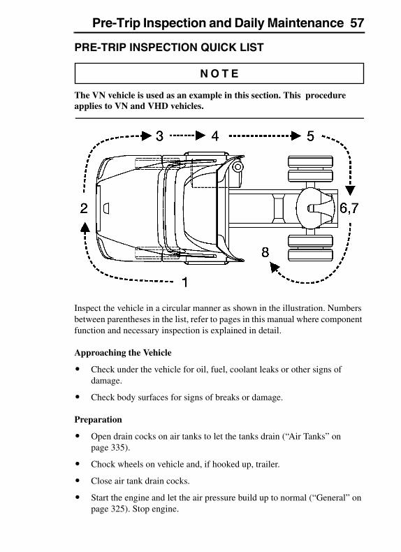
Pre-Trip Inspection and Daily Maintenance 57
PRE-TRIP INSPECTION QUICK LIST
The VN vehicle is used as an example in this section. This procedure applies to VN and VHD vehicles.
Inspect the vehicle in a circular manner as shown in the illustration. Numbers between parentheses in the list, refer to pages in this manual where component function and necessary inspection is explained in detail.
Approaching the Vehicle
� Check under the vehicle for oil, fuel, coolant leaks or other signs of damage.
� Check body surfaces for signs of breaks or damage.
Preparation
� Open drain cocks on air tanks to let the tanks drain (“Air Tanks” on page 335).
� Chock wheels on vehicle and, if hooked up, trailer.
� Close air tank drain cocks.
� Start the engine and let the air pressure build up to normal (“General” on page 325). Stop engine.
58 Pre-Trip Inspection and Daily Maintenance
� Switch on parking lights and hazard lights (“Light Control Panel” on page 124).
� Apply parking brakes (“Parking Brake/Trailer Supply Valves” on page 329).
� Pull the hood release lever, release the hood latches, (“Hood VN, VHD” on page 52). Raise hood.
Step 1: Left Side Of the Cab
Left Front Wheel
� Check condition of wheel rim. Especially look for cracks, missing lockrings, bent or broken studs, clamps or lugs.
� Check condition of tire: properly inflated, no serious cuts, bulges, tread wear or any signs of misalignment; valve stem not touching wheel, rim or brake drum; valve cap in place.
� Check wheel bearing and hub: no obvious leaking on outside or inside wheel. Verify correct oil level in hub.
Left Front Suspension
� Check condition of spring, spring hangers, shackles, U-bolts: no cracks, breaks or shifting.
� Check shock absorber condition.
Left Front Brake
� Condition of brake drum. With brakes released, look for a noticeable gap between lining and drum (This check cannot be made if dust covers are in place).
� Condition of brake air hose.
� Check brake chamber mounting bolts and bracket.
� Check slack adjuster and chamber pushrod travel.
Condition of Front Axle and Steering System, Left Side
� No loose, worn, bent, damaged or missing parts.
Pre-Trip Inspection and Daily Maintenance 59
Under Hood, Left Side
� Check coolant hose condition.
� Check condition of fan drive belts.
� Check engine and surrounding areas for coolant, oil and fuel leaks.
� Check wiring harnesses for signs of damage.
Step 2: Front Of Cab Area
Condition of Windshield
� Check for damage and clean if dirty (“Daily Maintenance” on page 71).
� Check windshield wiper arms for proper spring tension.
� Check wiper blades for any damage, “dead” rubber and attachment to arm.
Lights and Reflectors
� Lower hood and inspect parking, clearance and identification lights on hood and cab. They should be clean, operating and of the proper color.
� Reflectors clean and proper color.
� Turn on headlights. High and low beams should be operating and lenses clean. If equipped, check daytime running lights.
� Left and right front turn signal lights clean, operating and proper color. Raise hood.
Grille
� Check that charge air cooler and radiator or bugscreens are clean and undamaged.
Step 3: Right Side Of Cab Area
Right Front Wheel
� Check condition of wheel rim. Especially look for cracks, missing lockrings, bent or broken studs, clamps or lugs.
� Check condition of tire: properly inflated, no serious cuts, bulges, tread wear or any signs of misalignment; valve stem not touching wheel, rim or brake drum; valve cap in place.
� Check wheel bearing and hub: no obvious leaking on outside or inside wheel. Verify correct oil level in hub.
60 Pre-Trip Inspection and Daily Maintenance
Right Front Suspension
� Check condition of spring, spring hangers, shackles, U-bolts: no cracks, breaks or shifting.
� Shock absorber condition.
Right Front Brake
� Condition of brake drum. With brakes released, look for a noticeable gap between lining and drum (This check cannot be made if dust covers are in place).
� Condition of brake air hose: check for any chafing.
� Check brake chamber mounting bolts and bracket.
� Check slack adjuster and chamber pushrod travel. With brakes applied or released, look for conspicuously different positions of the slack adjusters.
Condition of Front Axle and Steering System, Right Side
� No loose, worn, bent, damaged or missing parts.
Under Hood, Right Side
� Check condition of coolant and heater hoses.
� Check condition of fan drive belts.
� Check engine and surrounding areas for coolant, oil and fuel leaks.
� Check fuel separator sight glass and drain if necessary. Check for leaks.
� Check wiring harnesses for signs of damage.
� Check air filter with brackets and hoses for loose connections or damage. Check filter gauge, if mounted on the filter.
Step 4: Right Saddle Tank Area
Right Fuel Tank(s)
� Securely mounted and not damaged or leaking.
� Fuel lines secure and not leaking. Check that shut-off valves are open.
� Tank(s) full of fuel. Cap on and secure.

Pre-Trip Inspection and Daily Maintenance 61
Condition of Visible Components
� Rear of engine: not leaking.
� Transmission: not leaking. If equipped with oil cooler, check cooler, hoses and fittings for leaks.
� Check drive shaft.
� Exhaust system: secure, not leaking, not touching wires, fuel or air tubing.
� Frame and cross members: no bends, cracks or breaks.
� Air tubing and electrical wiring: secured against snagging and chafing.
Step 5: Right Rear Vehicle Area
Dual Wheels, One Or Two Axles
� Check condition of wheels and rims. Especially look for cracks, missing lockrings, bent or broken spacers, studs, clamps or lugs.
� Check condition of tires: properly inflated, no serious cuts, bulges, tread wear or any signs of misalignment; valve stems not touching wheels, rims or brake drums; valve caps in place and no objects stuck between the wheels.
� Check that both tires are of same type, for example, not mixed radial and bias type and that their circumferences are matched.
� Check wheel bearing and hub: no obvious leaking on outside or inside wheel.
Suspension
� Check condition of springs (leaf or air), spring hangers, shackles and U-bolts.
� Axle alignment.
Brakes
� Condition of brake drums. With brakes released, look for a noticeable gap between lining and drum (This check cannot be made if dust covers are in place).
� Condition of brake hoses: check for any chafing.
� Check brake chamber mounting bolts and brackets.
62 Pre-Trip Inspection and Daily Maintenance
� Check slack adjusters and chamber push rod travel. With brakes applied or released, look for conspicuously different positions of the slack adjusters.
� Check spring brakes.
Step 6: Rear Of Vehicle Area
Frame Area
� Frame or cross members not bent, cracked or otherwise damaged or missing.
� Check that air tubing and electrical lines are properly secured to the frame with no damage or chafing.
Lights and Reflectors
� Tail lights, brake lights and turn signal lights: operating, clean and proper color.
Step 7: Coupling System Area
Fifth Wheel
� Securely mounted to the frame.
� No missing or damaged parts.
� Check that trunnion and plate are properly lubricated (“Safety Information” on page 383).
Sliding Fifth Wheel
� Mechanism not worn, bent, damaged or parts missing (“Fifth Wheel Slider (Optional)” on page 386).
� Properly lubricated.
� All locking pins present and locked in place.
� If air operated: no air leaks.
Air Tubing and Electric Lines Visible From This Point
� Should be secure from dangling.
� Both air lines and electric line should be free from damage, oil and grease.
Pre-Trip Inspection and Daily Maintenance 63
Step 8: Left Saddle Tank and Left Rear Vehicle Wheels Area
Dual Wheels, One Or Two Axles
� Check condition of wheels and rims. Especially look for cracks, missing lockrings, bent or broken spacers, studs, clamps or lugs.
� Check condition of tires: properly inflated, no serious cuts, bulges, tread wear or any signs of misalignment; valve stems not touching wheels, rims or brake drums; valve caps in place and no objects stuck between the wheels.
� Check that both tires are of same type, for example, not mixed radial and bias type and that their circumferences are matched.
� Check wheel bearing and hub: no obvious leaking on outside or inside wheel.
Suspension
� Check condition of springs (leaf or air), spring hangers, shackles and U-bolts, no cracks, breaks or shifting.
Brakes
� Condition of brake drums. With brakes released, look for a noticeable gap between lining and drum (This check cannot be made if dust covers are in place).
� Condition of brake hoses: check for any chafing.
� Check brake chamber mounting bolts and brackets.
� Check slack adjusters and chamber push rod travel. With brakes applied or released, look for conspicuously different positions of the slack adjusters.
� Check spring brakes.
Condition of Visible Components
� Transmission: not leaking.
� Drive shaft: looks OK.
� Exhaust system: secure, not leaking, not touching wires, fuel or air tubing.
� Frame and cross members: no bends, cracks or breaks.
� Air tubing and electrical wiring: secured against snagging and chafing.
64 Pre-Trip Inspection and Daily Maintenance
Left Fuel Tank(s)
� Securely mounted and not damaged or leaking.
� Fuel lines secure and not leaking. Check that shut-off valves are open.
� Tank(s) full of fuel. Cap on and secure.
Battery Area
� Open the battery box (“Batteries, Access and Charging” on page 349). Battery box securely mounted to vehicle.
� Batteries secured against movement (“Batteries, Access and Charging” on page 349).
� Battery cases not broken or leaking. Battery cables free from damage.
� Tops of batteries and terminals clean and free from foreign material.
� If equipped, replace battery lid and make sure it is securely fastened (“Batteries, Access and Charging” on page 349).
In the Cab
� Check steps and grab handles for looseness or breakage (“General Entry Guidelines” on page 40). Also, clean them if there is any substance that makes them slippery, which makes cab entry/exit hazardous.
� Start the engine. If equipped, check that exhaust rain cap opens when accelerating engine.
� Check gauges and telltale light function, see the “Instruments and Controls” section (“Instrument Cluster Overview” on page 130 to “Examples of Fault Symbols and Text” on page 154).
� Check function of low air warning (“Front and Rear Brake System Air Pressure Gauges” on page 137). Check the Driver Information Display (DID) for any fault codes (“Mid-Level and High-Level Instrument Cluster DID, General” on page 159).
� Check clutch function (“Clutch” on page 323). If equipped, check for clutch brake function.
� Check windshield wipers and washers (“Daily Maintenance” on page 71) and horns, including back-up alarm, if equipped.
� Clean inside windshield, door windows and instruments. Clean mirrors.
� Check temperature control and defroster (“General” on page 225). If equipped, check mirror heater.
Pre-Trip Inspection and Daily Maintenance 65
� Check condition of warning triangles, fire extinguisher and flares (“Safety Equipment” on page 101).
� Adjust the seat (“General” on page 252). Check mirror adjustment.
� Check safety belts for function and damage (“Inspection” on page 89).
� Apply service brakes. After initial drop, pressure should hold steady, or increase slightly, with engine at idle.
� Check steering wheel for excessive free play.
� Check for loose items in the cab. Secure them if necessary.
Hooking Up To Trailer
Hook-up Preparation
� Check kingpin and mounting plate on trailer, free from wear, bends or damage.
� Chock trailer wheels.
Fifth Wheel Or Trailer Hitch
� No visible space between fifth wheel and trailer (“Trailer Coupling Procedures” on page 388).
� Locking jaws around the shank and not the head of kingpin (“Trailer Coupling Procedures” on page 388).
� Release lever properly seated and safety latch/lock engaged (“Trailer Coupling Procedures” on page 388).
� Check all connections to dolly or trailer hitch and safety chains are secured.
� Check function of trailer air supply valve and trailer brakes.
Sliding Fifth Wheel
� Check that fifth wheel is not so far forward that the tractor frame will strike the landing gear during turns.
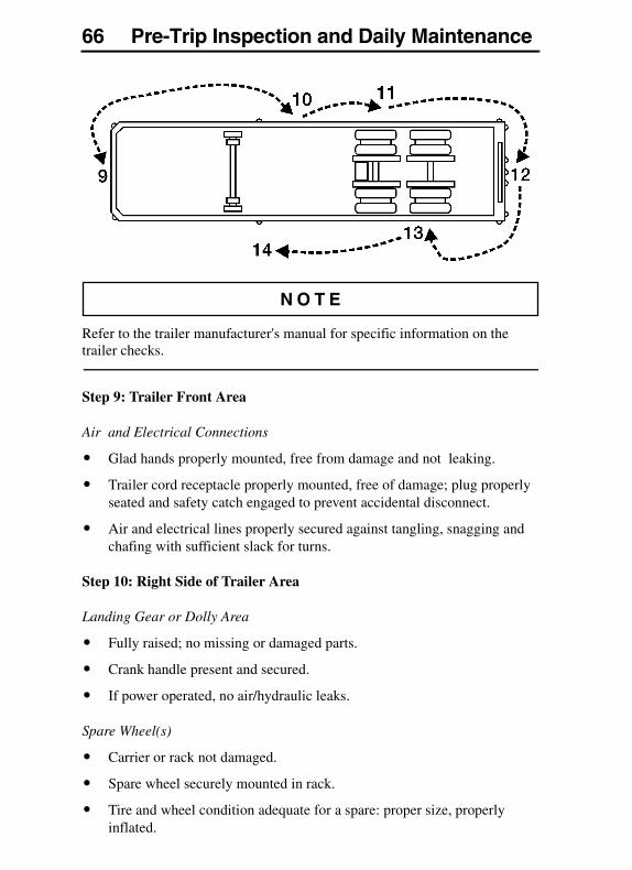
66 Pre-Trip Inspection and Daily Maintenance
Refer to the trailer manufacturer's manual for specific information on the trailer checks.
Step 9: Trailer Front Area
Air and Electrical Connections
� Glad hands properly mounted, free from damage and not leaking.
� Trailer cord receptacle properly mounted, free of damage; plug properly seated and safety catch engaged to prevent accidental disconnect.
� Air and electrical lines properly secured against tangling, snagging and chafing with sufficient slack for turns.
Step 10: Right Side of Trailer Area
Landing Gear or Dolly Area
� Fully raised; no missing or damaged parts.
� Crank handle present and secured.
� If power operated, no air/hydraulic leaks.
Spare Wheel(s)
� Carrier or rack not damaged.
� Spare wheel securely mounted in rack.
� Tire and wheel condition adequate for a spare: proper size, properly inflated.
Pre-Trip Inspection and Daily Maintenance 67
Lights and Reflectors
� Trailer side clearance lights: clean, operating and proper color.
� Reflectors clean and proper color.
Frame and Body
� Frame and crossmembers not bent, cracked, damaged or missing.
� Proper placarding.
� Body parts not damaged or missing.
Step 11: Right Rear Trailer Wheel
Dual Wheels, One Or Two Axles
� Check condition of wheels and rims. Especially look for cracks, missing lockrings, bent or broken spacers, studs, clamps or lugs.
� Check condition of tires: properly inflated, no serious cuts, bulges, tread wear or any signs of misalignment; valve stems not touching wheels, rims or brake drums; valve caps in place and no objects stuck between the wheels.
� Check that both tires are of same type, for example, not mixed radial and bias type and that their circumferences are matched.
� Check wheel bearing and hub: no obvious leaking on outside or inside wheel.
Suspension
� Condition of springs (leaf or air), spring hangers, shackles and U-bolts.
� Axle alignment.
� Condition of torque rod arms.
� If equipped with sliding axles, check position and alignment. Look for damaged, worn or missing parts, all locks present, fully in place and locked.
� Flexible air tubing not cracked, cut, crimped or otherwise damaged. Secured against tangling, dragging and chafing.
68 Pre-Trip Inspection and Daily Maintenance
Brakes
� Condition of brake drums. With brakes released, look for a noticeable gap between lining and drum (This check cannot be made if dust covers are in place).
� Condition of brake hoses: check for any chafing.
� Check brake chamber mounting bolts and brackets.
� Check slack adjusters and chamber push rod travel. With brakes applied or released, look for conspicuously different positions of the slack adjusters.
� Check spring brakes.
Step 12: Rear of Trailer Area
Lights and Reflectors
� Rear clearance, identification and tail lights clean, operating and proper color.
� Reflectors clean and proper color.
Cargo Securement
� Cargo properly blocked, braced, tied, chained, etc.
� Tailboard up and properly secured. End gates free from damage, properly secured in stake pockets.
� Canvas or tarp (if required) properly latched down to prevent water damage, tearing, billowing or blockage of either mirrors or tail lights.
� Rear doors securely closed, latched or locked; required security seals in place.
� Underside guard in place: not cracked, bent or broken.
Pre-Trip Inspection and Daily Maintenance 69
Step 13: Left Rear Trailer Wheels Area
Dual Wheels, One Or Two Axles
� Check condition of wheels and rims. Especially look for cracks, lockrings missing, bent or broken spacers, studs, clamps or lugs.
� Check condition of tires: properly inflated, no serious cuts, bulges, tread wear or any signs of misalignment; valve stems not touching wheels, rims or brake drums; valve caps in place and no objects stuck between the wheels.
� Check that both tires are of same type, for example, not mixed radial and bias type and that their circumferences are matched.
� Check wheel bearing and hub: no obvious leaking on outside or inside wheel.
Suspension
� Condition of springs (leaf or air), spring hangers, shackles and U-bolts.
� Axle alignment.
� Condition of torque rod arms.
� If equipped with sliding axles, check position and alignment. Look for damaged, worn or missing parts, all locks present, fully in place and locked.
� Flexible air tubing not cracked, cut, crimped or otherwise damaged. It should be secured against tangling, dragging and chafing.
Brakes
� Condition of brake drums. With brakes released, look for a noticeable gap between lining and drum (This check can not be made if dust covers are in place).
� Condition of brake hoses: check for any chafing.
� Check brake chamber mounting bolts and brackets.
� Check slack adjusters and chamber push rod travel. With brakes applied or released, look for conspicuously different positions of the slack adjusters.
� Check spring brakes.
70 Pre-Trip Inspection and Daily Maintenance
Step 14: Left Side of Trailer Area
Landing Gear or Dolly Area
� Fully raised; no missing or damaged parts.
� Crank handle present and secured.
� If power operated, no air/hydraulic leaks.
Spare Wheel(s)
� Spare wheel securely mounted in rack with no damage to rack.
� Tire and wheel condition adequate for a spare: proper size, properly inflated.
Lights and Reflectors
� Trailer side clearance lights: clean, operating and proper color.
� Reflectors clean and proper color.
Frame and Body
� Frame and crossmembers not bent, cracked, damaged or missing.
� Proper placarding.
� Body parts not damaged or missing.
Before Leaving the Parking Area
� Remove chocks from the wheels.
� Test trailer hook-up by slowly pulling while applying the trailer brakes with the trailer brake hand control valve.
� Test the service brakes before leaving the parking area.
� Test parking brakes by stopping on a 20% grade and applying the parking brakes. The parking brakes shall hold the combined vehicle and trailer without moving.
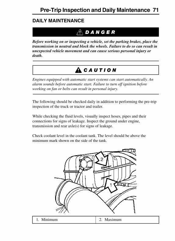
Pre-Trip Inspection and Daily Maintenance 71
DAILY MAINTENANCE
Before working on or inspecting a vehicle, set the parking brakes, place the transmission in neutral and block the wheels. Failure to do so can result in unexpected vehicle movement and can cause serious personal injury or death.
Engines equipped with automatic start systems can start automatically. An alarm sounds before automatic start. Failure to turn off ignition before working on fan or belts can result in personal injury.
The following should be checked daily in addition to performing the pre-trip inspection of the truck or tractor and trailer.
While checking the fluid levels, visually inspect hoses, pipes and their connections for signs of leakage. Inspect the ground under engine, transmission and rear axle(s) for signs of leakage.
Check coolant level in the coolant tank. The level should be above the minimum mark shown on the side of the tank.
1. Minimum 2. Maximum
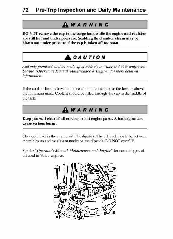
72 Pre-Trip Inspection and Daily Maintenance
DO NOT remove the cap to the surge tank while the engine and radiator are still hot and under pressure. Scalding fluid and/or steam may be blown out under pressure if the cap is taken off too soon.
Add only premixed coolant made up of 50% clean water and 50% antifreeze. See the “Operator's Manual, Maintenance & Engine” for more detailed information.
If the coolant level is low, add more coolant to the tank so the level is above the minimum mark. Coolant should be filled through the cap in the middle of the tank.
Keep yourself clear of all moving or hot engine parts. A hot engine can cause serious burns.
Check oil level in the engine with the dipstick. The oil level should be between the minimum and maximum marks on the dipstick. DO NOT overfill!
See the “Operator's Manual, Maintenance and Engine” for correct types of oil used in Volvo engines.
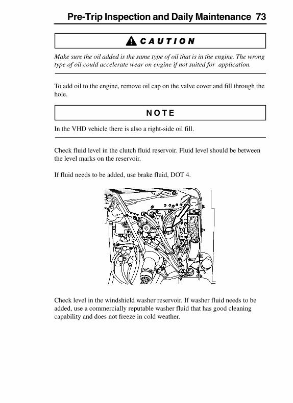
Pre-Trip Inspection and Daily Maintenance 73
Make sure the oil added is the same type of oil that is in the engine. The wrong type of oil could accelerate wear on engine if not suited for application.
To add oil to the engine, remove oil cap on the valve cover and fill through the hole.
In the VHD vehicle there is also a right-side oil fill.
Check fluid level in the clutch fluid reservoir. Fluid level should be between the level marks on the reservoir.
If fluid needs to be added, use brake fluid, DOT 4.
Check level in the windshield washer reservoir. If washer fluid needs to be added, use a commercially reputable washer fluid that has good cleaning capability and does not freeze in cold weather.
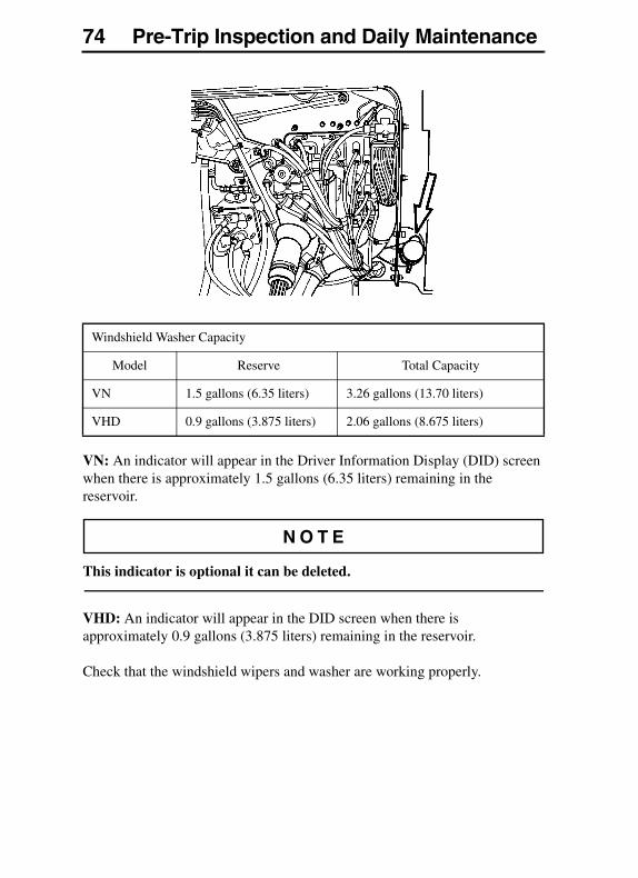
74 Pre-Trip Inspection and Daily Maintenance
VN: An indicator will appear in the Driver Information Display (DID) screen when there is approximately 1.5 gallons (6.35 liters) remaining in the reservoir.
This indicator is optional it can be deleted.
VHD: An indicator will appear in the DID screen when there is approximately 0.9 gallons (3.875 liters) remaining in the reservoir.
Check that the windshield wipers and washer are working properly.
Windshield Washer Capacity
Model Reserve Total Capacity
VN 1.5 gallons (6.35 liters) 3.26 gallons (13.70 liters)
VHD 0.9 gallons (3.875 liters) 2.06 gallons (8.675 liters)
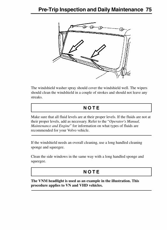
Pre-Trip Inspection and Daily Maintenance 75
The windshield washer spray should cover the windshield well. The wipers should clean the windshield in a couple of strokes and should not leave any streaks.
Make sure that all fluid levels are at their proper levels. If the fluids are not at their proper levels, add as necessary. Refer to the “Operator's Manual, Maintenance and Engine” for information on what types of fluids are recommended for your Volvo vehicle.
If the windshield needs an overall cleaning, use a long handled cleaning sponge and squeegee.
Clean the side windows in the same way with a long handled sponge and squeegee.
The VNM headlight is used as an example in the illustration. This procedure applies to VN and VHD vehicles.
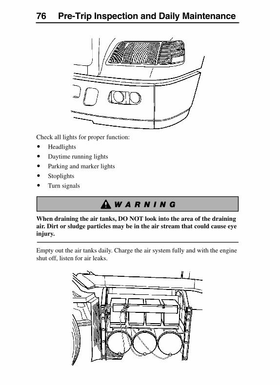
76 Pre-Trip Inspection and Daily Maintenance
Check all lights for proper function:
� Headlights
� Daytime running lights
� Parking and marker lights
� Stoplights
� Turn signals
When draining the air tanks, DO NOT look into the area of the draining air. Dirt or sludge particles may be in the air stream that could cause eye injury.
Empty out the air tanks daily. Charge the air system fully and with the engine shut off, listen for air leaks.
Additional Safety Features 77ADDITIONAL SAFETY FEATURES
SAFETY BELTS
General
Safety belts must be properly worn at all times by the driver and all passengers while the vehicle is in motion even if the vehicle is equipped with a Supplemental Restraint System (SRS or air bag). Failure to do so can result in serious personal injury or death in the event of a collision.
Fasten the safety belt before starting to drive. Trying to fasten the safety belt while the vehicle is moving may lead to an accident, causing serious personal injury or death.
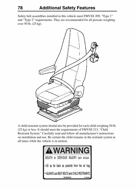
78 Additional Safety Features
Safety belt assemblies installed in this vehicle meet FMVSS 209, “Type 1” and “Type 2” requirements. They are recommended for all persons weighing over 50 lb. (25 kg).
A child restraint system should also be provided for each child weighing 50 lb. (25 kg) or less. It should meet the requirements of FMVSS 213, “Child Restraint System.” Carefully read and follow all manufacturer's instructions on installation and use. Be certain the child remains in the restraint system at all times while the vehicle is in motion.
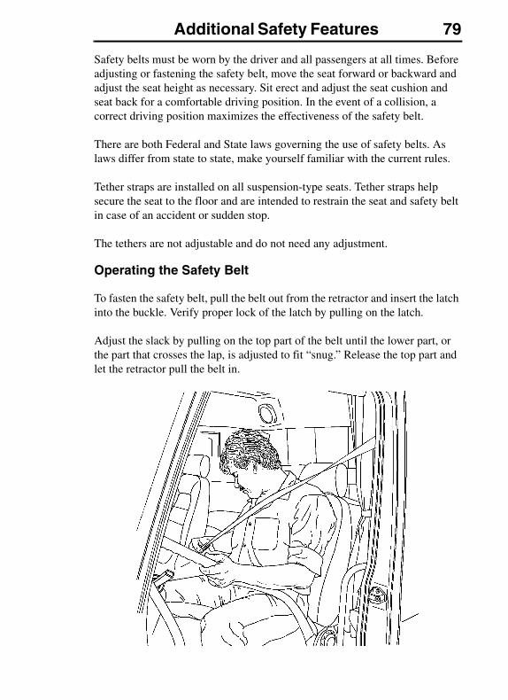
Additional Safety Features 79
Safety belts must be worn by the driver and all passengers at all times. Before adjusting or fastening the safety belt, move the seat forward or backward and adjust the seat height as necessary. Sit erect and adjust the seat cushion and seat back for a comfortable driving position. In the event of a collision, a correct driving position maximizes the effectiveness of the safety belt.
There are both Federal and State laws governing the use of safety belts. As laws differ from state to state, make yourself familiar with the current rules.
Tether straps are installed on all suspension-type seats. Tether straps help secure the seat to the floor and are intended to restrain the seat and safety belt in case of an accident or sudden stop.
The tethers are not adjustable and do not need any adjustment.
Operating the Safety Belt
To fasten the safety belt, pull the belt out from the retractor and insert the latch into the buckle. Verify proper lock of the latch by pulling on the latch.
Adjust the slack by pulling on the top part of the belt until the lower part, or the part that crosses the lap, is adjusted to fit “snug.” Release the top part and let the retractor pull the belt in.
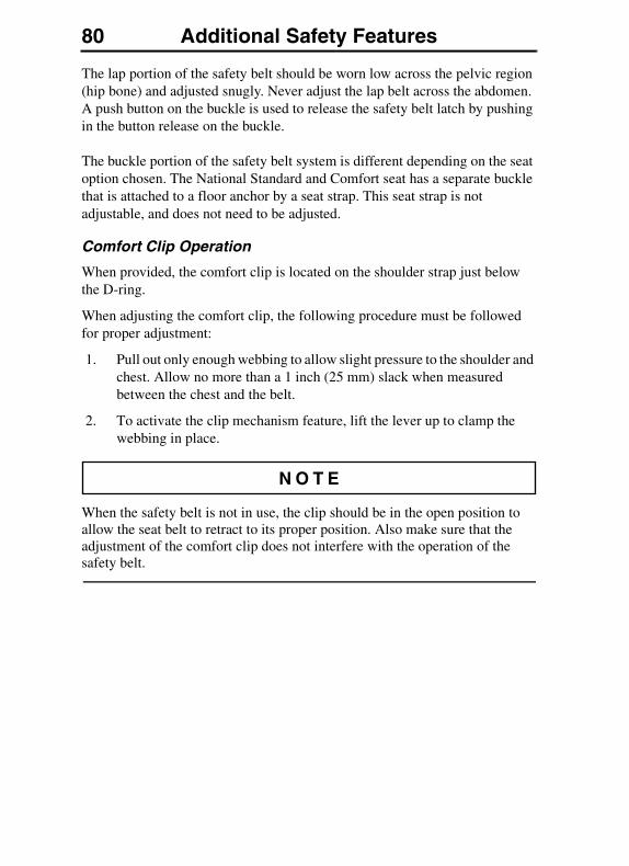
80 Additional Safety Features
The lap portion of the safety belt should be worn low across the pelvic region (hip bone) and adjusted snugly. Never adjust the lap belt across the abdomen. A push button on the buckle is used to release the safety belt latch by pushing in the button release on the buckle.
The buckle portion of the safety belt system is different depending on the seat option chosen. The National Standard and Comfort seat has a separate buckle that is attached to a floor anchor by a seat strap. This seat strap is not adjustable, and does not need to be adjusted.
Comfort Clip Operation
When provided, the comfort clip is located on the shoulder strap just below the D-ring.
When adjusting the comfort clip, the following procedure must be followed for proper adjustment:
1. Pull out only enough webbing to allow slight pressure to the shoulder and chest. Allow no more than a 1 inch (25 mm) slack when measured between the chest and the belt.
2. To activate the clip mechanism feature, lift the lever up to clamp the webbing in place.
When the safety belt is not in use, the clip should be in the open position to allow the seat belt to retract to its proper position. Also make sure that the adjustment of the comfort clip does not interfere with the operation of the safety belt.
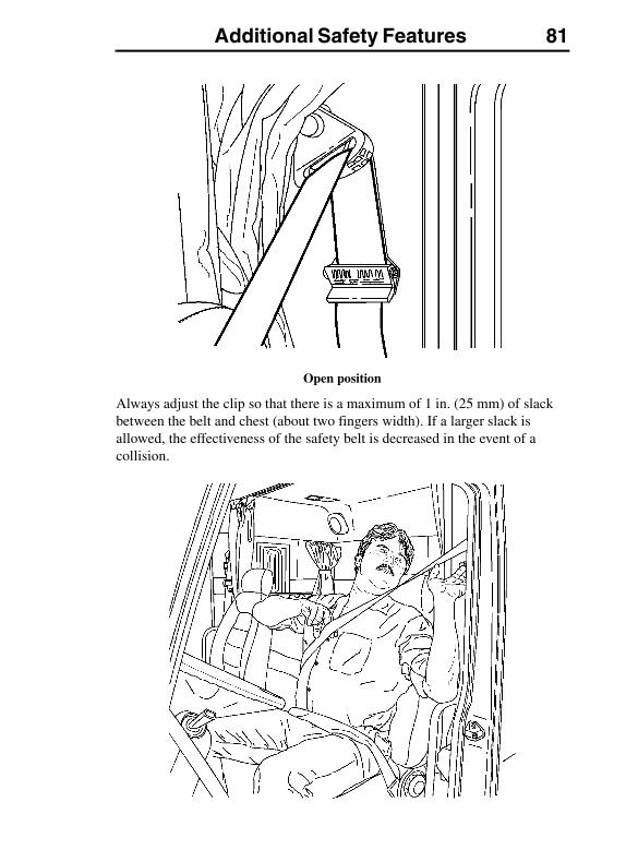
Additional Safety Features 81
Open position
Always adjust the clip so that there is a maximum of 1 in. (25 mm) of slack between the belt and chest (about two fingers width). If a larger slack is allowed, the effectiveness of the safety belt is decreased in the event of a collision.
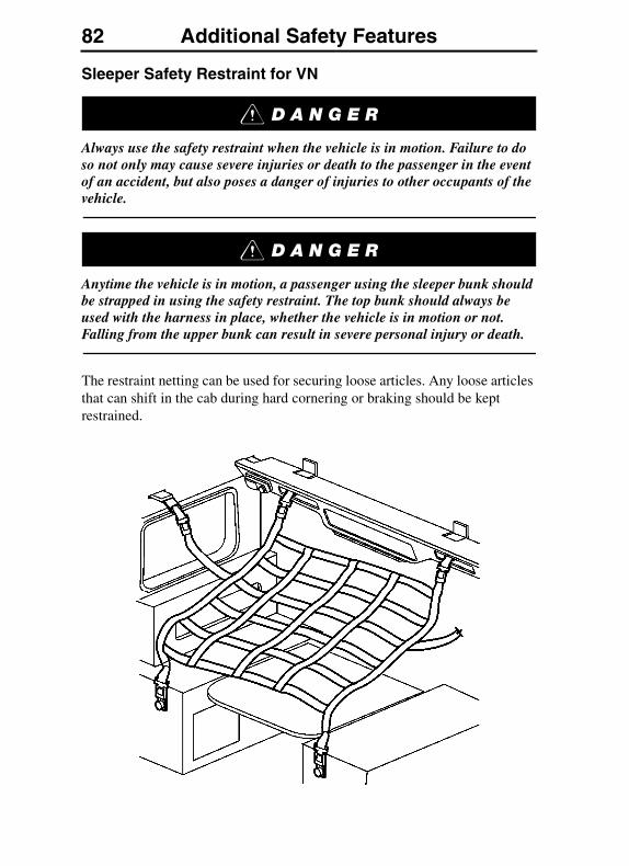
82 Additional Safety Features
Sleeper Safety Restraint for VN
Always use the safety restraint when the vehicle is in motion. Failure to do so not only may cause severe injuries or death to the passenger in the event of an accident, but also poses a danger of injuries to other occupants of the vehicle.
Anytime the vehicle is in motion, a passenger using the sleeper bunk should be strapped in using the safety restraint. The top bunk should always be used with the harness in place, whether the vehicle is in motion or not. Falling from the upper bunk can result in severe personal injury or death.
The restraint netting can be used for securing loose articles. Any loose articles that can shift in the cab during hard cornering or braking should be kept restrained.
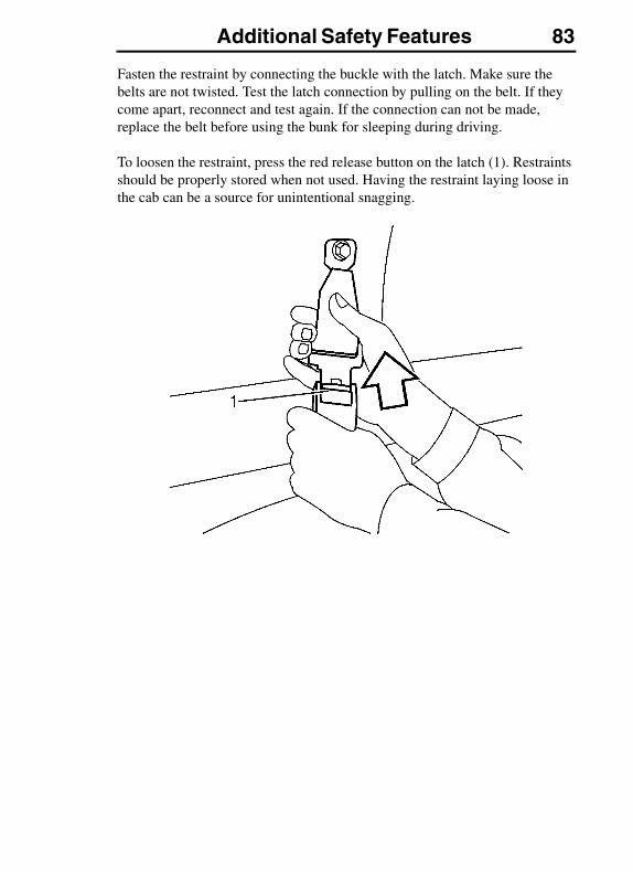
Additional Safety Features 83
Fasten the restraint by connecting the buckle with the latch. Make sure the belts are not twisted. Test the latch connection by pulling on the belt. If they come apart, reconnect and test again. If the connection can not be made, replace the belt before using the bunk for sleeping during driving.
To loosen the restraint, press the red release button on the latch (1). Restraints should be properly stored when not used. Having the restraint laying loose in the cab can be a source for unintentional snagging.
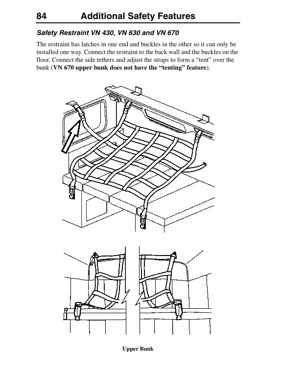
84 Additional Safety Features
Safety Restraint VN 430, VN 630 and VN 670
The restraint has latches in one end and buckles in the other so it can only be installed one way. Connect the restraint to the back wall and the buckles on the floor. Connect the side tethers and adjust the straps to form a “tent” over the bunk (VN 670 upper bunk does not have the “tenting” feature).
Upper Bunk
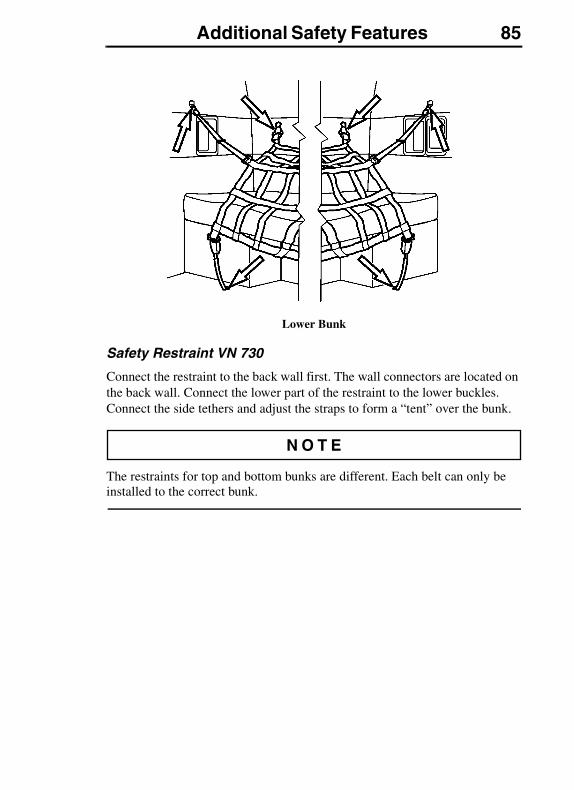
Additional Safety Features 85
Lower Bunk
Safety Restraint VN 730
Connect the restraint to the back wall first. The wall connectors are located on the back wall. Connect the lower part of the restraint to the lower buckles. Connect the side tethers and adjust the straps to form a “tent” over the bunk.
The restraints for top and bottom bunks are different. Each belt can only be installed to the correct bunk.
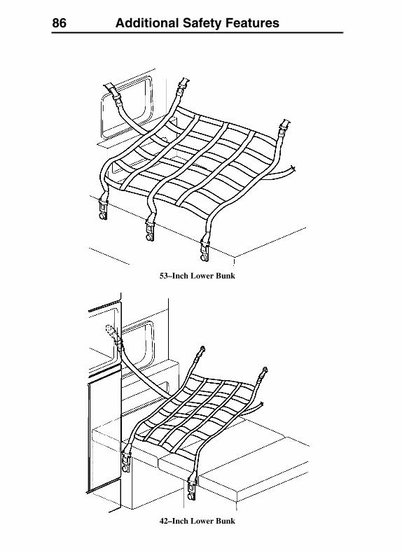
86 Additional Safety Features
53–Inch Lower Bunk
42–Inch Lower Bunk
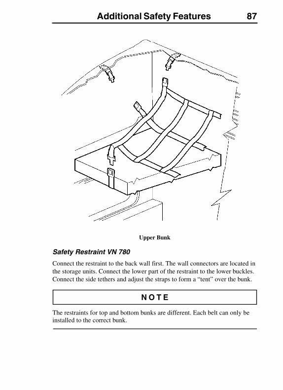
Additional Safety Features 87
Upper Bunk
Safety Restraint VN 780
Connect the restraint to the back wall first. The wall connectors are located in the storage units. Connect the lower part of the restraint to the lower buckles. Connect the side tethers and adjust the straps to form a “tent” over the bunk.
The restraints for top and bottom bunks are different. Each belt can only be installed to the correct bunk.
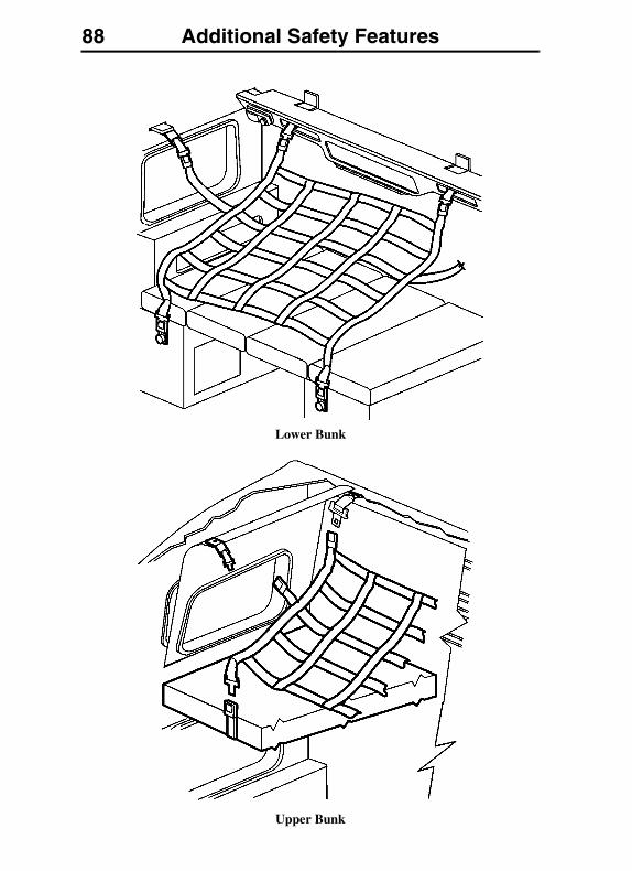
88 Additional Safety Features
Lower Bunk
Upper Bunk
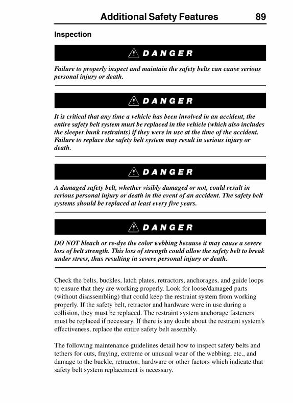
Additional Safety Features 89
Inspection
Failure to properly inspect and maintain the safety belts can cause serious personal injury or death.
It is critical that any time a vehicle has been involved in an accident, the entire safety belt system must be replaced in the vehicle (which also includes the sleeper bunk restraints) if they were in use at the time of the accident. Failure to replace the safety belt system may result in serious injury or death.
A damaged safety belt, whether visibly damaged or not, could result in serious personal injury or death in the event of an accident. The safety belt systems should be replaced at least every five years.
DO NOT bleach or re-dye the color webbing because it may cause a severe loss of belt strength. This loss of strength could allow the safety belt to break under stress, thus resulting in severe personal injury or death.
Check the belts, buckles, latch plates, retractors, anchorages, and guide loops to ensure that they are working properly. Look for loose/damaged parts (without disassembling) that could keep the restraint system from working properly. If the safety belt, retractor and hardware were in use during a collision, they must be replaced. The restraint system anchorage fasteners must be replaced if necessary. If there is any doubt about the restraint system's effectiveness, replace the entire safety belt assembly.
The following maintenance guidelines detail how to inspect safety belts and tethers for cuts, fraying, extreme or unusual wear of the webbing, etc., and damage to the buckle, retractor, hardware or other factors which indicate that safety belt system replacement is necessary.

90 Additional Safety Features
Check the web wear at the buckle/latch area. The webbing must be closely examined to determine if there are any cuts, fraying or extreme wear in the webbing. Cuts, fraying or excessive wear would indicate the need for replacement of the safety belt system.
The D-loop web guide is an area where almost constant movement of the safety belt webbing occurs because of the relative movement between the seat and the cab. This constant movement forms an area where wear will often occur. The webbing must be closely examined to determine if there are any cuts, fraying or extreme wear in the webbing. Cuts, fraying or excessive wear would indicate the need for replacement of the safety belt system.
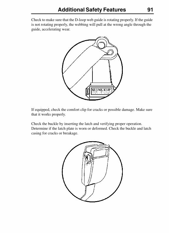
Additional Safety Features 91
Check to make sure that the D-loop web guide is rotating properly. If the guide is not rotating properly, the webbing will pull at the wrong angle through the guide, accelerating wear.
If equipped, check the comfort clip for cracks or possible damage. Make sure that it works properly.
Check the buckle by inserting the latch and verifying proper operation. Determine if the latch plate is worn or deformed. Check the buckle and latch casing for cracks or breakage.
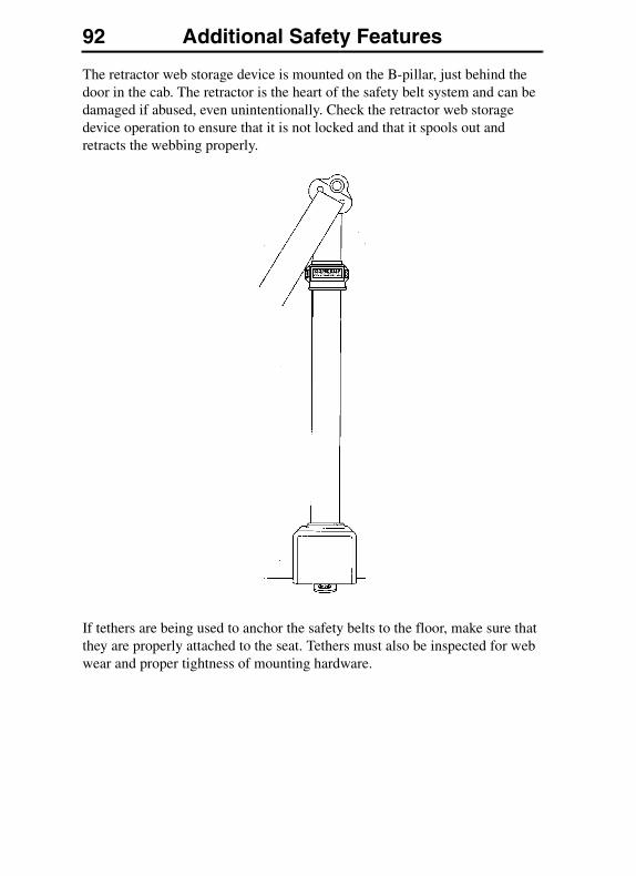
92 Additional Safety Features
The retractor web storage device is mounted on the B-pillar, just behind the door in the cab. The retractor is the heart of the safety belt system and can be damaged if abused, even unintentionally. Check the retractor web storage device operation to ensure that it is not locked and that it spools out and retracts the webbing properly.
If tethers are being used to anchor the safety belts to the floor, make sure that they are properly attached to the seat. Tethers must also be inspected for web wear and proper tightness of mounting hardware.
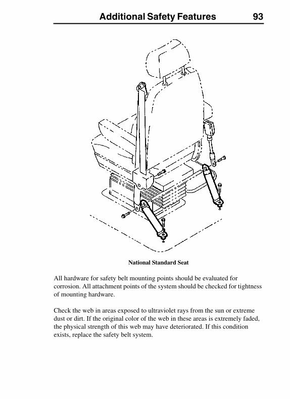
Additional Safety Features 93
National Standard Seat
All hardware for safety belt mounting points should be evaluated for corrosion. All attachment points of the system should be checked for tightness of mounting hardware.
Check the web in areas exposed to ultraviolet rays from the sun or extreme dust or dirt. If the original color of the web in these areas is extremely faded, the physical strength of this web may have deteriorated. If this condition exists, replace the safety belt system.
94 Additional Safety Features
Important Facts About Safety Belts in Heavy Trucks
The high mileage associated with heavy trucks, the continual relative movement of the seat with the cab, the possible contact with the vehicle seat or other parts of the cab structure, and the potential exposure of this safety belt to severe environmental conditions make it crucial to inspect the seat belt system regularly. It is recommended that the system is inspected every 15,000 miles (24,000 km) or more often if the vehicle is exposed to severe environmental or vocational conditions. Any safety belt system that shows cuts, fraying, extreme or unusual wear, significant discolorations due to ultraviolet ray exposure, dusty-dirty conditions, abrasion to the safety belt webbing or damage to the buckle, latch plate, retractor, hardware or any other obvious problem should be replaced immediately, regardless of the mileage.
Once replacement of the safety belt has been determined necessary, be certain that it is replaced only with a Volvo original replacement safety belt. See your authorized Volvo Truck dealer for replacement. Your Volvo safety belt system has been developed and tested specifically for heavy trucks. Replace it only with the exact same design that the vehicle was equipped with.
If the inspection indicates that any other part of the safety belt system requires replacement, the entire belt system must be replaced. An installation guide is attached to every replacement system, entitled “Three-Point Safety Belt Installation Guide.” There are separate safety belt instruction guides for suspension and stationary seats. Use the proper guide for your type of seat and follow the instructions very closely. It is vitally important that all components are mounted back in the same positions as the original components that were removed. This will maintain the design integrity of the mounting points for the safety belt assembly.
SRS AIRBAG
The SRS airbag is intended to supplement — not replace — the standard safety belt. The airbag is not deployed when the truck is hit from behind, from the side or if it rolls over. For best protection, sit in a normal, upright position. Always wear the safety belt.
For added safety, the vehicle may be equipped with an airbag or SRS (Supplemental Restraint System) as a supplement to the standard three-point anchored safety belt. The SRS is designed to reduce the risk of injury to the driver's face and upper part of the body. Together with the safety belt, the airbag helps prevent the driver from being thrown against the steering wheel, windshield or other hard surfaces in the cab.
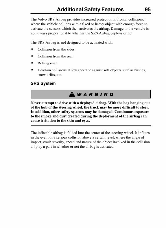
Additional Safety Features 95
The Volvo SRS Airbag provides increased protection in frontal collisions, where the vehicle collides with a fixed or heavy object with enough force to activate the sensors which then activates the airbag. Damage to the vehicle is not always proportional to whether the SRS Airbag deploys or not.
The SRS Airbag is not designed to be activated with:
� Collision from the sides
� Collision from the rear
� Rolling over
� Head-on collisions at low speed or against soft objects such as bushes, snow drifts, etc.
SRS System
Never attempt to drive with a deployed airbag. With the bag hanging out of the hub of the steering wheel, the truck may be more difficult to steer. In addition, other safety systems may be damaged. Continuous exposure to the smoke and dust created during the deployment of the airbag can cause irritation to the skin and eyes.
The inflatable airbag is folded into the center of the steering wheel. It inflates in the event of a serious collision above a certain level, where the angle of impact, crash severity, speed and nature of the object involved in the collision all play a part in whether or not the airbag is activated.
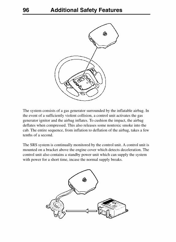
96 Additional Safety Features
The system consists of a gas generator surrounded by the inflatable airbag. In the event of a sufficiently violent collision, a control unit activates the gas generator ignitor and the airbag inflates. To cushion the impact, the airbag deflates when compressed. This also releases some nontoxic smoke into the cab. The entire sequence, from inflation to deflation of the airbag, takes a few tenths of a second.
The SRS system is continually monitored by the control unit. A control unit is mounted on a bracket above the engine cover which detects deceleration. The control unit also contains a standby power unit which can supply the system with power for a short time, incase the normal supply breaks.
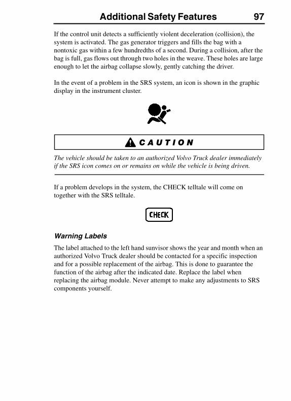
Additional Safety Features 97
If the control unit detects a sufficiently violent deceleration (collision), the system is activated. The gas generator triggers and fills the bag with a nontoxic gas within a few hundredths of a second. During a collision, after the bag is full, gas flows out through two holes in the weave. These holes are large enough to let the airbag collapse slowly, gently catching the driver.
In the event of a problem in the SRS system, an icon is shown in the graphic display in the instrument cluster.
The vehicle should be taken to an authorized Volvo Truck dealer immediately if the SRS icon comes on or remains on while the vehicle is being driven.
If a problem develops in the system, the CHECK telltale will come on together with the SRS telltale.
Warning Labels
The label attached to the left hand sunvisor shows the year and month when an authorized Volvo Truck dealer should be contacted for a specific inspection and for a possible replacement of the airbag. This is done to guarantee the function of the airbag after the indicated date. Replace the label when replacing the airbag module. Never attempt to make any adjustments to SRS components yourself.
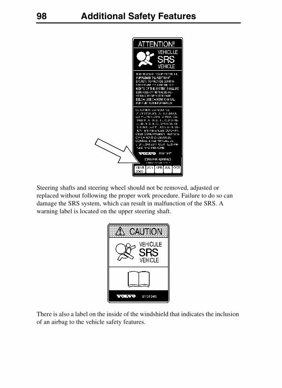
98 Additional Safety Features
Steering shafts and steering wheel should not be removed, adjusted or replaced without following the proper work procedure. Failure to do so can damage the SRS system, which can result in malfunction of the SRS. A warning label is located on the upper steering shaft.
There is also a label on the inside of the windshield that indicates the inclusion of an airbag to the vehicle safety features.
Additional Safety Features 99
When equipped with an airbag, a label with the correct procedure for protecting small children and protecting the driver is attached to the left hand, overhead storage lid or back of sunvisor.
Any queries concerning the SRS system should be directed to an authorized Volvo Truck dealer. There is no maintenance required for the SRS system until the date on the warning label located on the left hand sunvisor.
Never attempt to repair any part of the SRS system. Any interference with the system may cause it to malfunction and result in serious injury or death.
Work on the system may only be carried out by an authorized Volvo Truck dealer.
To allow the SRS system to work as designed:
� Never drive an SRS system equipped vehicle with the hands on the steering wheel pad/airbag module.
� No objects, accessory equipment or stickers may be placed on, attached to or installed near the SRS cover in the center of the steering wheel.
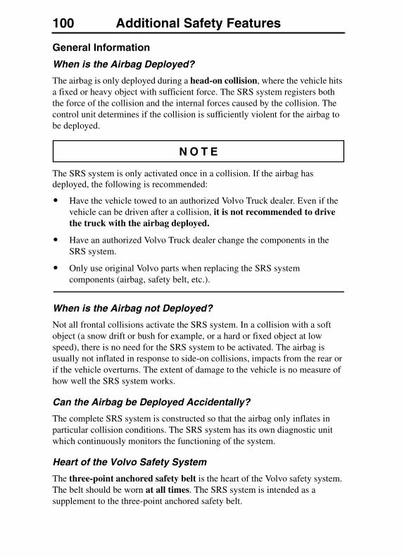
100 Additional Safety Features
General Information
When is the Airbag Deployed?
The airbag is only deployed during a head-on collision, where the vehicle hits a fixed or heavy object with sufficient force. The SRS system registers both the force of the collision and the internal forces caused by the collision. The control unit determines if the collision is sufficiently violent for the airbag to be deployed.
The SRS system is only activated once in a collision. If the airbag has deployed, the following is recommended:
� Have the vehicle towed to an authorized Volvo Truck dealer. Even if the vehicle can be driven after a collision, it is not recommended to drive the truck with the airbag deployed.
� Have an authorized Volvo Truck dealer change the components in the SRS system.
� Only use original Volvo parts when replacing the SRS system components (airbag, safety belt, etc.).
When is the Airbag not Deployed?
Not all frontal collisions activate the SRS system. In a collision with a soft object (a snow drift or bush for example, or a hard or fixed object at low speed), there is no need for the SRS system to be activated. The airbag is usually not inflated in response to side-on collisions, impacts from the rear or if the vehicle overturns. The extent of damage to the vehicle is no measure of how well the SRS system works.
Can the Airbag be Deployed Accidentally?
The complete SRS system is constructed so that the airbag only inflates in particular collision conditions. The SRS system has its own diagnostic unit which continuously monitors the functioning of the system.
Heart of the Volvo Safety System
The three-point anchored safety belt is the heart of the Volvo safety system. The belt should be worn at all times. The SRS system is intended as a supplement to the three-point anchored safety belt.

Additional Safety Features 101
SAFETY EQUIPMENT
Safety triangles and fire extinguishers are available as optional equipment. The fire extinguisher should be located by the base of the driver seat, between the seat and the door.
Always store the warning triangles in the box after use.
Warning Triangles, Day Cab & VHD
The warning triangles are stored in a box that is strapped behind the passenger seat.

102 Additional Safety Features
Sleeper Cab
The warning triangles are stored in a box, which is inside the exterior luggage compartment.
Additional Safety Features 103
VORAD COLLISION WARNING SYSTEM
The Eaton VORAD computerized Collision Warning System constantly monitors vehicles ahead with a front end mounted radar and in a blind spot area with an optional side mounted radar. The Collision Warning System warns the driver of potentially dangerous situations by activating visual and audible alerts.
The Eaton VORAD Collision Warning System is intended solely as an aid for an alert and conscientious professional driver. It is not to be used or relied upon to operate the vehicle. Use this system together with rear view mirrors and other instrumentation to maintain safe operation of the vehicle. Operate a VORAD equipped vehicle in the same safe manner as if VORAD was not installed.
The Eaton VORAD Collision Warning System is not a substitute for safe driving procedures nor will it compensate for any driver impairment, such as drugs, alcohol or fatigue.
The Eaton VORAD Collision Warning System may provide little or no warning for some hazards like: alerts for pedestrians, animals, oncoming vehicles and cross traffic. SmartCruise will not react to stationary objects and it does not have the capability to stop the vehicle.
Failure to follow these instructions may lead to a vehicle accident resulting in severe personal injury or death.
If your vehicle is equipped with the Eaton VORAD Collision Warning System, read the manufacturer's Driver Reference Manual before taking the vehicle on the road.

104 Notes
Instruments and Controls 105INSTRUMENTS AND CONTROLS
OPERATING
Before driving this vehicle, locate the instruments and controls, and become thoroughly familiar with their operation. After starting and when driving, ensure that the instrument readings are normal.
Availability of gauges depends on the options the driver selects. All gauges and telltales may not be used in all vehicles.
The VN and VHD dash layout is the same, however, the switches and certain switch positions are different.
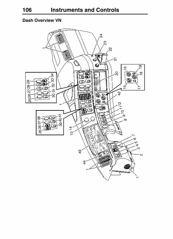
106 Instruments and Controls
Dash Overview VN
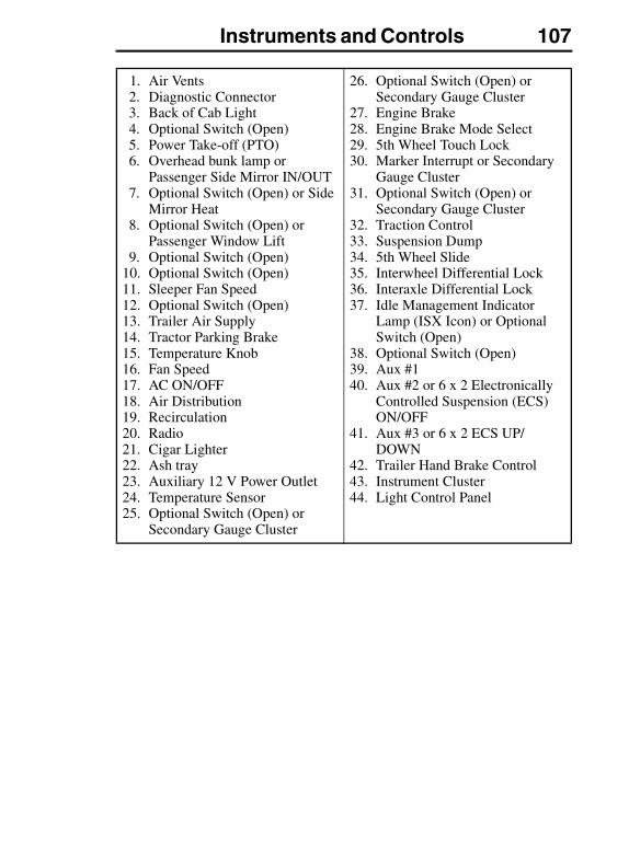
Instruments and Controls 107
1. Air Vents2. Diagnostic Connector3. Back of Cab Light4. Optional Switch (Open)5. Power Take-off (PTO)6. Overhead bunk lamp or
Passenger Side Mirror IN/OUT7. Optional Switch (Open) or Side
Mirror Heat8. Optional Switch (Open) or
Passenger Window Lift9. Optional Switch (Open)
10. Optional Switch (Open)11. Sleeper Fan Speed12. Optional Switch (Open)13. Trailer Air Supply14. Tractor Parking Brake15. Temperature Knob16. Fan Speed 17. AC ON/OFF18. Air Distribution19. Recirculation20. Radio21. Cigar Lighter22. Ash tray23. Auxiliary 12 V Power Outlet24. Temperature Sensor25. Optional Switch (Open) or
Secondary Gauge Cluster
26. Optional Switch (Open) or Secondary Gauge Cluster
27. Engine Brake28. Engine Brake Mode Select29. 5th Wheel Touch Lock30. Marker Interrupt or Secondary
Gauge Cluster31. Optional Switch (Open) or
Secondary Gauge Cluster32. Traction Control33. Suspension Dump34. 5th Wheel Slide35. Interwheel Differential Lock36. Interaxle Differential Lock37. Idle Management Indicator
Lamp (ISX Icon) or Optional Switch (Open)
38. Optional Switch (Open)39. Aux #140. Aux #2 or 6 x 2 Electronically
Controlled Suspension (ECS) ON/OFF
41. Aux #3 or 6 x 2 ECS UP/DOWN
42. Trailer Hand Brake Control43. Instrument Cluster44. Light Control Panel
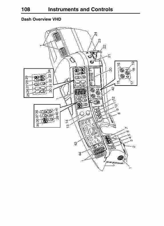
108 Instruments and Controls
Dash Overview VHD
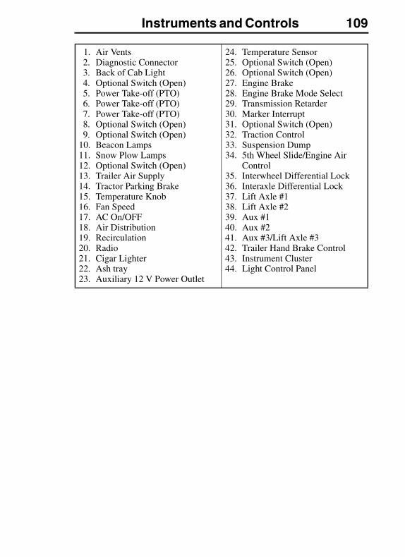
Instruments and Controls 109
1. Air Vents2. Diagnostic Connector3. Back of Cab Light4. Optional Switch (Open)5. Power Take-off (PTO)6. Power Take-off (PTO)7. Power Take-off (PTO)8. Optional Switch (Open)9. Optional Switch (Open)
10. Beacon Lamps11. Snow Plow Lamps12. Optional Switch (Open)13. Trailer Air Supply14. Tractor Parking Brake15. Temperature Knob16. Fan Speed 17. AC On/OFF18. Air Distribution19. Recirculation20. Radio21. Cigar Lighter22. Ash tray23. Auxiliary 12 V Power Outlet
24. Temperature Sensor25. Optional Switch (Open)26. Optional Switch (Open)27. Engine Brake28. Engine Brake Mode Select29. Transmission Retarder30. Marker Interrupt 31. Optional Switch (Open)32. Traction Control33. Suspension Dump34. 5th Wheel Slide/Engine Air
Control35. Interwheel Differential Lock36. Interaxle Differential Lock37. Lift Axle #138. Lift Axle #239. Aux #140. Aux #241. Aux #3/Lift Axle #342. Trailer Hand Brake Control43. Instrument Cluster44. Light Control Panel
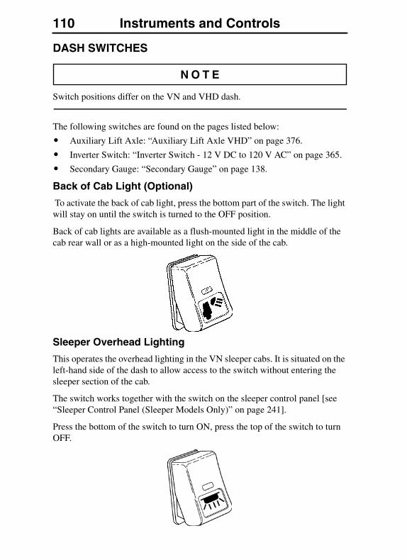
110 Instruments and Controls
DASH SWITCHES
Switch positions differ on the VN and VHD dash.
The following switches are found on the pages listed below:
� Auxiliary Lift Axle: “Auxiliary Lift Axle VHD” on page 376.
� Inverter Switch: “Inverter Switch - 12 V DC to 120 V AC” on page 365.
� Secondary Gauge: “Secondary Gauge” on page 138.
Back of Cab Light (Optional)
To activate the back of cab light, press the bottom part of the switch. The light will stay on until the switch is turned to the OFF position.
Back of cab lights are available as a flush-mounted light in the middle of the cab rear wall or as a high-mounted light on the side of the cab.
Sleeper Overhead Lighting
This operates the overhead lighting in the VN sleeper cabs. It is situated on the left-hand side of the dash to allow access to the switch without entering the sleeper section of the cab.
The switch works together with the switch on the sleeper control panel [see “Sleeper Control Panel (Sleeper Models Only)” on page 241].
Press the bottom of the switch to turn ON, press the top of the switch to turn OFF.
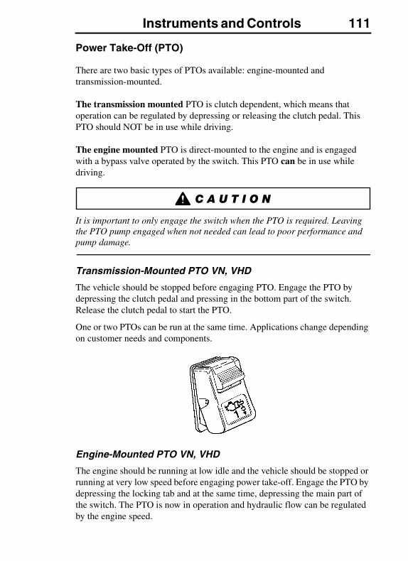
Instruments and Controls 111
Power Take-Off (PTO)
There are two basic types of PTOs available: engine-mounted and transmission-mounted.
The transmission mounted PTO is clutch dependent, which means that operation can be regulated by depressing or releasing the clutch pedal. This PTO should NOT be in use while driving.
The engine mounted PTO is direct-mounted to the engine and is engaged with a bypass valve operated by the switch. This PTO can be in use while driving.
It is important to only engage the switch when the PTO is required. Leaving the PTO pump engaged when not needed can lead to poor performance and pump damage.
Transmission-Mounted PTO VN, VHD
The vehicle should be stopped before engaging PTO. Engage the PTO by depressing the clutch pedal and pressing in the bottom part of the switch. Release the clutch pedal to start the PTO.
One or two PTOs can be run at the same time. Applications change depending on customer needs and components.
Engine-Mounted PTO VN, VHD
The engine should be running at low idle and the vehicle should be stopped or running at very low speed before engaging power take-off. Engage the PTO by depressing the locking tab and at the same time, depressing the main part of the switch. The PTO is now in operation and hydraulic flow can be regulated by the engine speed.
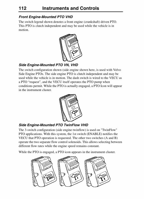
112 Instruments and Controls
Front Engine-Mounted PTO VHDThe switch legend shown denotes a front engine (crankshaft) driven PTO. This PTO is clutch independent and may be used while the vehicle is in motion.
Side Engine-Mounted PTO VN, VHDThe switch configuration shown (side engine shown here, is used with Volvo Side Engine PTOs. The side engine PTO is clutch independent and may be used while the vehicle is in motion. The dash switch is wired to the VECU as a PTO “request”, and the VECU itself operates the PTO pump when conditions permit. While the PTO is actually engaged, a PTO Icon will appear in the instrument cluster.
Side Engine-Mounted PTO TwinFlow VHDThe 3-switch configuration (side engine twinflow) is used on "TwinFlow" PTO applications. With this system, the 1st switch (ENABLE) notifies the VECU that PTO operation is requested. The other two switches (A and B) operate the two separate flow control solenoids. This allows selecting between different flow rates while the engine speed remains constant.
While the PTO is engaged, a PTO icon appears in the instrument cluster.
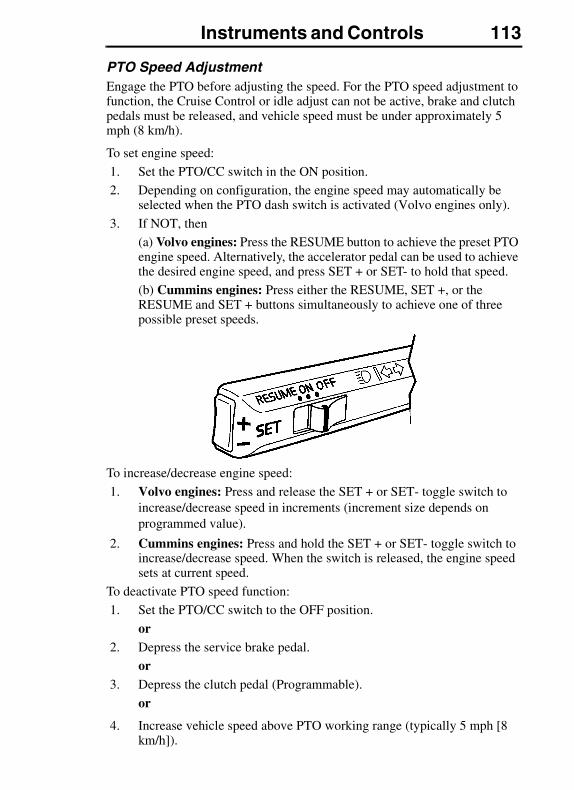
Instruments and Controls 113
PTO Speed AdjustmentEngage the PTO before adjusting the speed. For the PTO speed adjustment to function, the Cruise Control or idle adjust can not be active, brake and clutch pedals must be released, and vehicle speed must be under approximately 5 mph (8 km/h).
To set engine speed:
1. Set the PTO/CC switch in the ON position.
2. Depending on configuration, the engine speed may automatically be selected when the PTO dash switch is activated (Volvo engines only).
3. If NOT, then
(a) Volvo engines: Press the RESUME button to achieve the preset PTO engine speed. Alternatively, the accelerator pedal can be used to achieve the desired engine speed, and press SET + or SET- to hold that speed.
(b) Cummins engines: Press either the RESUME, SET +, or the RESUME and SET + buttons simultaneously to achieve one of three possible preset speeds.
To increase/decrease engine speed:
1. Volvo engines: Press and release the SET + or SET- toggle switch to increase/decrease speed in increments (increment size depends on programmed value).
2. Cummins engines: Press and hold the SET + or SET- toggle switch to increase/decrease speed. When the switch is released, the engine speed sets at current speed.
To deactivate PTO speed function:
1. Set the PTO/CC switch to the OFF position.
or2. Depress the service brake pedal.
or3. Depress the clutch pedal (Programmable).
or
4. Increase vehicle speed above PTO working range (typically 5 mph [8 km/h]).
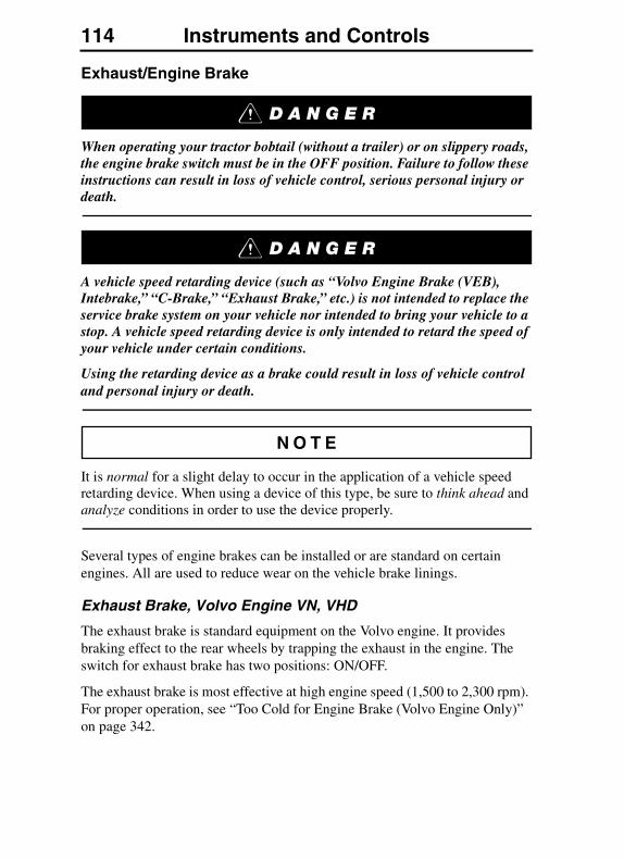
114 Instruments and Controls
Exhaust/Engine Brake
When operating your tractor bobtail (without a trailer) or on slippery roads, the engine brake switch must be in the OFF position. Failure to follow these instructions can result in loss of vehicle control, serious personal injury or death.
A vehicle speed retarding device (such as “Volvo Engine Brake (VEB), Intebrake,” “C-Brake,” “Exhaust Brake,” etc.) is not intended to replace the service brake system on your vehicle nor intended to bring your vehicle to a stop. A vehicle speed retarding device is only intended to retard the speed of your vehicle under certain conditions.
Using the retarding device as a brake could result in loss of vehicle control and personal injury or death.
It is normal for a slight delay to occur in the application of a vehicle speed retarding device. When using a device of this type, be sure to think ahead and analyze conditions in order to use the device properly.
Several types of engine brakes can be installed or are standard on certain engines. All are used to reduce wear on the vehicle brake linings.
Exhaust Brake, Volvo Engine VN, VHD
The exhaust brake is standard equipment on the Volvo engine. It provides braking effect to the rear wheels by trapping the exhaust in the engine. The switch for exhaust brake has two positions: ON/OFF.
The exhaust brake is most effective at high engine speed (1,500 to 2,300 rpm). For proper operation, see “Too Cold for Engine Brake (Volvo Engine Only)” on page 342.
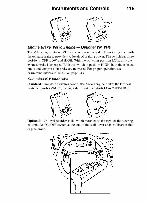
Instruments and Controls 115
Engine Brake, Volvo Engine — Optional VN, VHDThe Volvo Engine Brake (VEB) is a compression brake. It works together with the exhaust brake to provide two levels of braking power. The switch has three positions: OFF, LOW and HIGH. With the switch in position LOW, only the exhaust brake is engaged. With the switch in position HIGH, both the exhaust brake and compression brake are activated. For proper operation, see “Cummins Intebrake (ISX)” on page 343.
Cummins ISX IntebrakeStandard: Two dash switches control the 3-level engine brake; the left dash switch controls ON/OFF, the right dash switch controls LOW/MED/HIGH.
Optional: A 6-level retarder stalk switch mounted to the right of the steering column. An ON/OFF switch at the end of the stalk lever enables/disables the engine brake.

116 Instruments and Controls
Fuel Pressure
The fuel priming switch is located on the right-hand side of the steering column, in the dash. This is a non-locking switch, used to pressurize and bleed the D12D engine. For detailed information about bleeding the engine, refer to the Maintenance and Engine Operator's Manual.
Marker Interrupt
This switch interrupts power to the marker lights when held down. When released, it springs back to the ON position and returns power to the marker lights.
Fan Speed
The sleeper fan switch located in the dash, controls the sleeper fan speed. The switch in the sleeper control module performs the same function as the dash switch.
Press the top part of the switch to increase the fan speed, press the lower part to decrease fan speed.

Instruments and Controls 117
Traction Control (TCS)
If the vehicle is equipped with a Traction Control System (TCS), the switch can be used to disable the traction control feature, and therefore increase wheel spin. This may be useful for decreasing the chances of getting bogged down when driving in heavy snow, slush or muddy conditions. See “Volvo Exhaust Brake VN, VHD” on page 341 for more information.
Snow Plow, VHD (Optional)
Seen “Dash Overview VHD” on page 108 for location of Snow Plow switch.
Vehicles specified with this option have the following:
� Turn ON low beam Snow Plow headlamps.
� Turn OFF main headlamps low , high beam, fog and driving lights.
� In driving mode, DRL remains ON.
� Snow Plow direction indicators are available.
Beacon Light, VHD (Optional)
See “Dash Overview VHD” on page 108 for location of Beacon Light switch.

118 Instruments and Controls
STEERING COLUMN SWITCHES
Windshield Wiper/Washer
The wiper/washer functions are operated by the same switch. The wipers have normal and fast speeds which are activated by moving the lever down one or two positions. To let the wipers engage for a few passes, lightly depress the lever until the wipers start and hold it there. The wipers return to the parking position when the lever is released.
The interval wiper function is engaged by moving the lever up. The normal programmed speed is one pass every 10 seconds. To shorten the interval time, move the lever to normal wipe position and then to the interval position again when the next wiper pass is desired. This way, the interval can be programmed between 1 to 10 seconds between each pass.
To operate the windshield washer, pull the lever toward the steering wheel. If washer fluid needs to be added, use a commercially reputable washer fluid that has good cleaning capability and does not freeze in cold weather.
An indicator will appear in the DID when the washer fluid level is low. See “Daily Maintenance” on page 71 for washer level capacity. A 10 second activation delay allows for fluid slosh.
In the VNM 200 Day Cab (Short fairing) the washer fluid indicator is NOT displayed in the instrument cluster
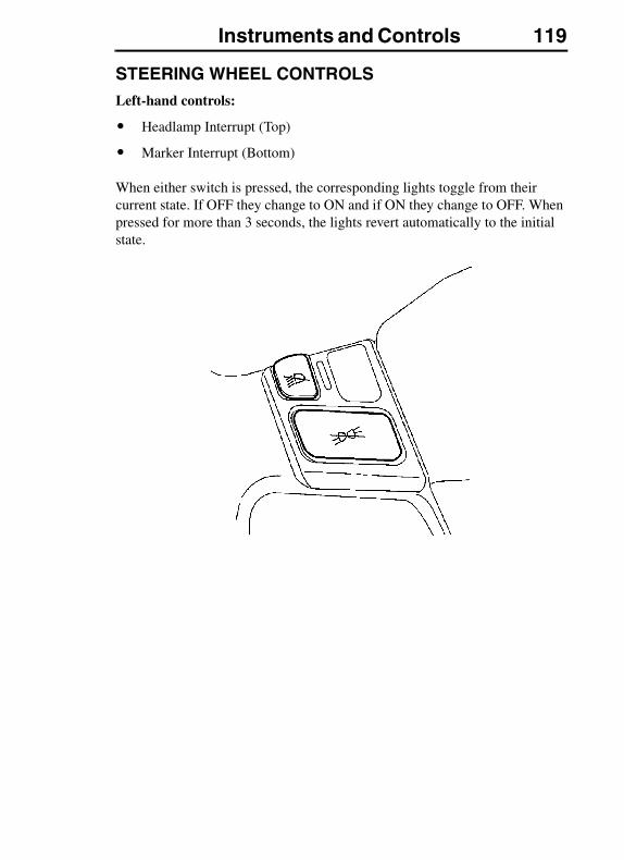
Instruments and Controls 119
STEERING WHEEL CONTROLSLeft-hand controls:
� Headlamp Interrupt (Top)
� Marker Interrupt (Bottom)
When either switch is pressed, the corresponding lights toggle from their current state. If OFF they change to ON and if ON they change to OFF. When pressed for more than 3 seconds, the lights revert automatically to the initial state.
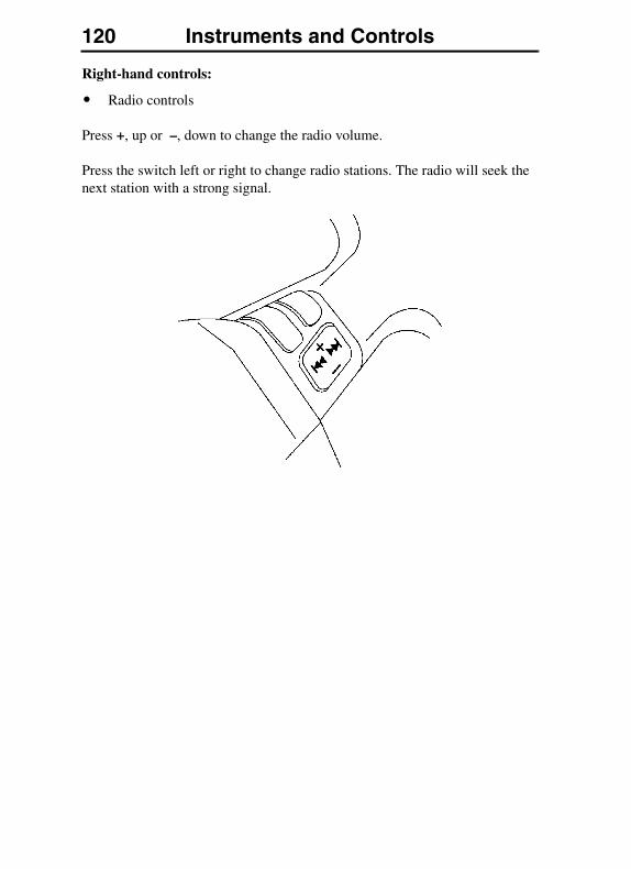
120 Instruments and Controls
Right-hand controls:
� Radio controls
Press +, up or –, down to change the radio volume.
Press the switch left or right to change radio stations. The radio will seek the next station with a strong signal.
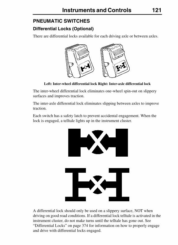
Instruments and Controls 121
PNEUMATIC SWITCHES
Differential Locks (Optional)
There are differential locks available for each driving axle or between axles.
Left: Inter-wheel differential lock Right: Inter-axle differential lock
The inter-wheel differential lock eliminates one-wheel spin-out on slippery surfaces and improves traction.
The inter-axle differential lock eliminates slipping between axles to improve traction.
Each switch has a safety latch to prevent accidental engagement. When the lock is engaged, a telltale lights up in the instrument cluster.
A differential lock should only be used on a slippery surface, NOT when driving on good road conditions. If a differential lock telltale is activated in the instrument cluster, do not make turns until the telltale has gone out. See “Differential Locks” on page 374 for information on how to properly engage and drive with differential locks engaged.
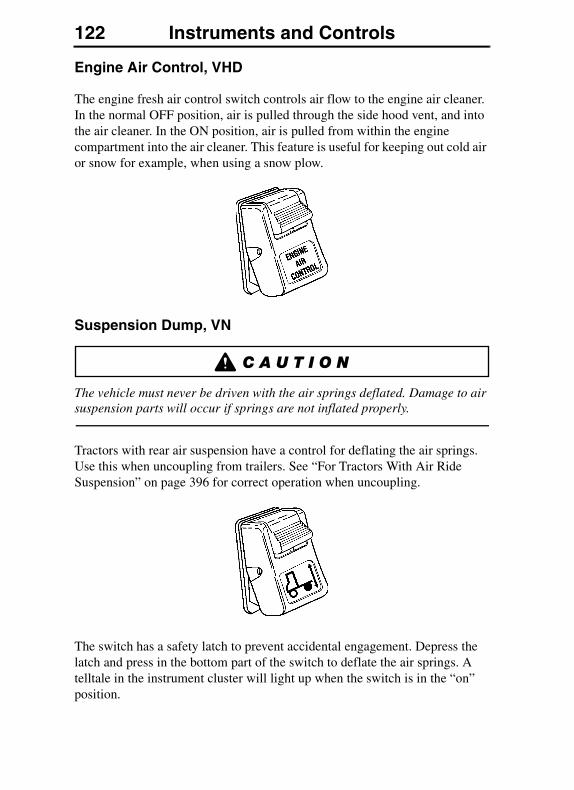
122 Instruments and Controls
Engine Air Control, VHD
The engine fresh air control switch controls air flow to the engine air cleaner. In the normal OFF position, air is pulled through the side hood vent, and into the air cleaner. In the ON position, air is pulled from within the engine compartment into the air cleaner. This feature is useful for keeping out cold air or snow for example, when using a snow plow.
Suspension Dump, VN
The vehicle must never be driven with the air springs deflated. Damage to air suspension parts will occur if springs are not inflated properly.
Tractors with rear air suspension have a control for deflating the air springs. Use this when uncoupling from trailers. See “For Tractors With Air Ride Suspension” on page 396 for correct operation when uncoupling.
The switch has a safety latch to prevent accidental engagement. Depress the latch and press in the bottom part of the switch to deflate the air springs. A telltale in the instrument cluster will light up when the switch is in the “on” position.
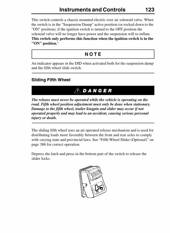
Instruments and Controls 123
This switch controls a chassis mounted electric over air solenoid valve. When the switch is in the "Suspension Dump" active position (or rocked down to the "ON" position), if the ignition switch is turned to the OFF position the solenoid valve will no longer have power and the suspension will re-inflate. This switch only performs this function when the ignition switch is in the "ON" position."
An indicator appears in the DID when activated both for the suspension dump and the fifth wheel slide switch.
Sliding Fifth Wheel
The release must never be operated while the vehicle is operating on the road. Fifth wheel position adjustment must only be done when stationary. Damage to the fifth wheel, trailer kingpin and slider may occur if not operated properly and may lead to an accident, causing serious personal injury or death.
The sliding fifth wheel uses an air operated release mechanism and is used for distributing loads more favorably between the front and rear axles to comply with varying state and provincial laws. See “Fifth Wheel Slider (Optional)” on page 386 for correct operation.
Depress the latch and press in the bottom part of the switch to release the slider locks.
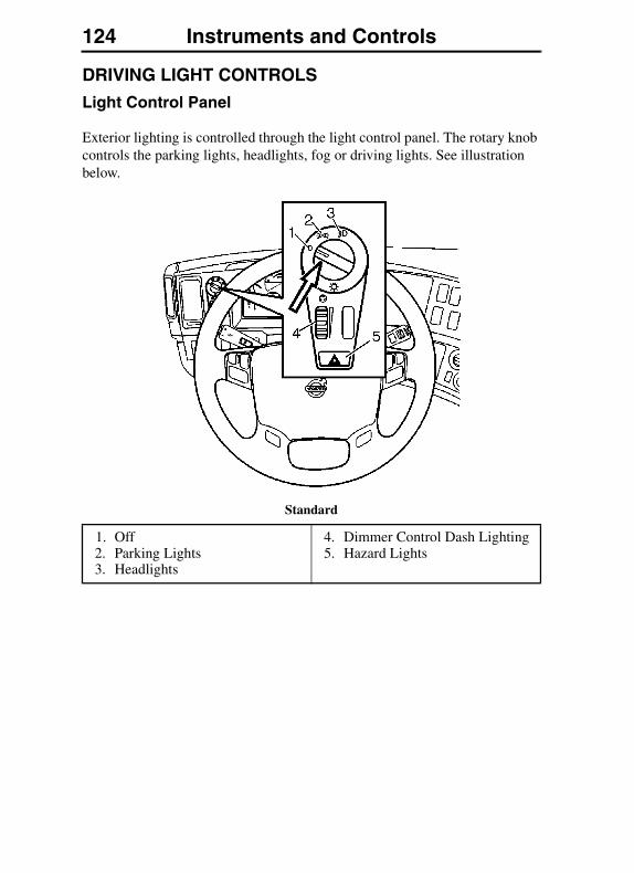
124 Instruments and Controls
DRIVING LIGHT CONTROLS
Light Control Panel
Exterior lighting is controlled through the light control panel. The rotary knob controls the parking lights, headlights, fog or driving lights. See illustration below.
Standard
1. Off2. Parking Lights3. Headlights
4. Dimmer Control Dash Lighting5. Hazard Lights

Instruments and Controls 125
Optional
Driving and Fog Lights, VNM & VNL
Fog and driving lights are wired so they are turned on only when the headlight control is on. Fog lights are used with the low beam headlights. Driving lights are used with the high beam headlights. Switching from low to high beam will automatically switch from fog lights to driving lights.
Driving and fog lights should be used when driving conditions require additional lighting. The driving or fog lights should NOT be used in traffic where they might distract other drivers thereby creating a safety hazard.
Driving and fog lights are also available on the VHD vehicle.
1. Off2. Parking Lights3. Headlights4. Fog or Driving Lights
5. Hazard Lights6. Dimmer Control (Dash)
Lighting
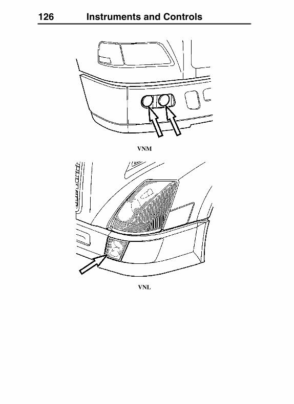
126 Instruments and Controls
VNM
VNL
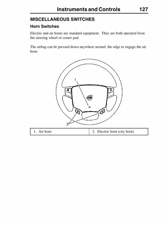
Instruments and Controls 127
MISCELLANEOUS SWITCHES
Horn Switches
Electric and air horns are standard equipment. They are both operated from the steering wheel or center pad.
The airbag can be pressed down anywhere around the edge to engage the air horn.
1. Air horn 2. Electric horn (city horn)
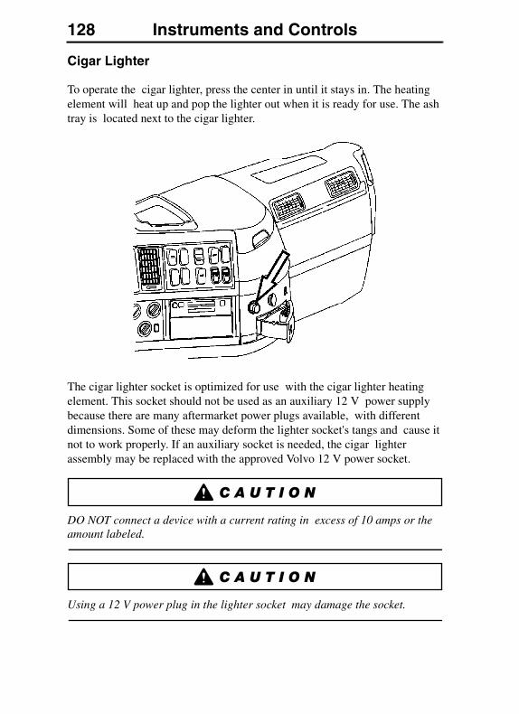
128 Instruments and Controls
Cigar Lighter
To operate the cigar lighter, press the center in until it stays in. The heating element will heat up and pop the lighter out when it is ready for use. The ash tray is located next to the cigar lighter.
The cigar lighter socket is optimized for use with the cigar lighter heating element. This socket should not be used as an auxiliary 12 V power supply because there are many aftermarket power plugs available, with different dimensions. Some of these may deform the lighter socket's tangs and cause it not to work properly. If an auxiliary socket is needed, the cigar lighter assembly may be replaced with the approved Volvo 12 V power socket.
DO NOT connect a device with a current rating in excess of 10 amps or the amount labeled.
Using a 12 V power plug in the lighter socket may damage the socket.

Instruments and Controls 129
OPTIONAL SWITCHES
Auxiliary Switches
Generic switches are available for auxiliary functions that are installed by the customer. These switches can be purchased from your authorized Volvo Truck dealer.
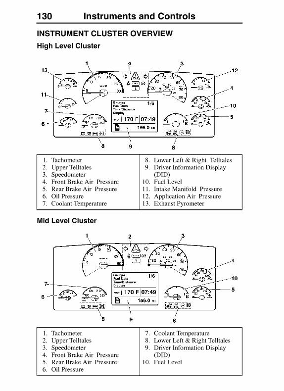
130 Instruments and Controls
INSTRUMENT CLUSTER OVERVIEW
High Level Cluster
Mid Level Cluster
1. Tachometer2. Upper Telltales3. Speedometer4. Front Brake Air Pressure5. Rear Brake Air Pressure6. Oil Pressure7. Coolant Temperature
8. Lower Left & Right Telltales9. Driver Information Display
(DID)10. Fuel Level11. Intake Manifold Pressure12. Application Air Pressure13. Exhaust Pyrometer
1. Tachometer2. Upper Telltales3. Speedometer4. Front Brake Air Pressure5. Rear Brake Air Pressure6. Oil Pressure
7. Coolant Temperature8. Lower Left & Right Telltales9. Driver Information Display
(DID)10. Fuel Level
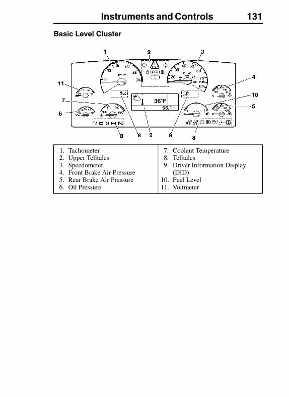
Instruments and Controls 131
Basic Level Cluster
1. Tachometer2. Upper Telltales3. Speedometer4. Front Brake Air Pressure5. Rear Brake Air Pressure6. Oil Pressure
7. Coolant Temperature8. Telltales9. Driver Information Display
(DID)10. Fuel Level11. Voltmeter
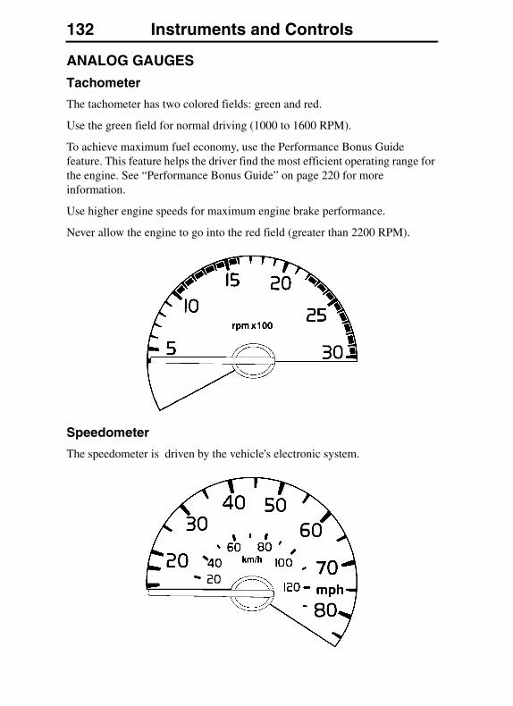
132 Instruments and Controls
ANALOG GAUGES
Tachometer
The tachometer has two colored fields: green and red.
Use the green field for normal driving (1000 to 1600 RPM).
To achieve maximum fuel economy, use the Performance Bonus Guide feature. This feature helps the driver find the most efficient operating range for the engine. See “Performance Bonus Guide” on page 220 for more information.
Use higher engine speeds for maximum engine brake performance.
Never allow the engine to go into the red field (greater than 2200 RPM).
Speedometer
The speedometer is driven by the vehicle's electronic system.
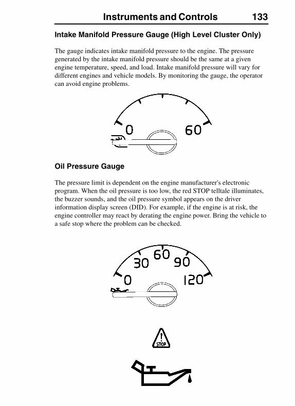
Instruments and Controls 133
Intake Manifold Pressure Gauge (High Level Cluster Only)
The gauge indicates intake manifold pressure to the engine. The pressure generated by the intake manifold pressure should be the same at a given engine temperature, speed, and load. Intake manifold pressure will vary for different engines and vehicle models. By monitoring the gauge, the operator can avoid engine problems.
Oil Pressure Gauge
The pressure limit is dependent on the engine manufacturer's electronic program. When the oil pressure is too low, the red STOP telltale illuminates, the buzzer sounds, and the oil pressure symbol appears on the driver information display screen (DID). For example, if the engine is at risk, the engine controller may react by derating the engine power. Bring the vehicle to a safe stop where the problem can be checked.
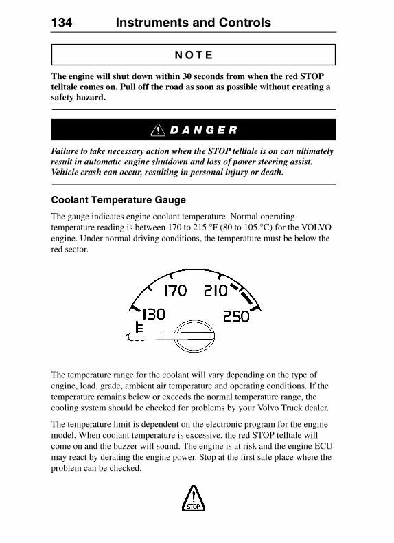
134 Instruments and Controls
The engine will shut down within 30 seconds from when the red STOP telltale comes on. Pull off the road as soon as possible without creating a safety hazard.
Failure to take necessary action when the STOP telltale is on can ultimately result in automatic engine shutdown and loss of power steering assist. Vehicle crash can occur, resulting in personal injury or death.
Coolant Temperature Gauge
The gauge indicates engine coolant temperature. Normal operating temperature reading is between 170 to 215 °F (80 to 105 °C) for the VOLVO engine. Under normal driving conditions, the temperature must be below the red sector.
The temperature range for the coolant will vary depending on the type of engine, load, grade, ambient air temperature and operating conditions. If the temperature remains below or exceeds the normal temperature range, the cooling system should be checked for problems by your Volvo Truck dealer.
The temperature limit is dependent on the electronic program for the engine model. When coolant temperature is excessive, the red STOP telltale will come on and the buzzer will sound. The engine is at risk and the engine ECU may react by derating the engine power. Stop at the first safe place where the problem can be checked.
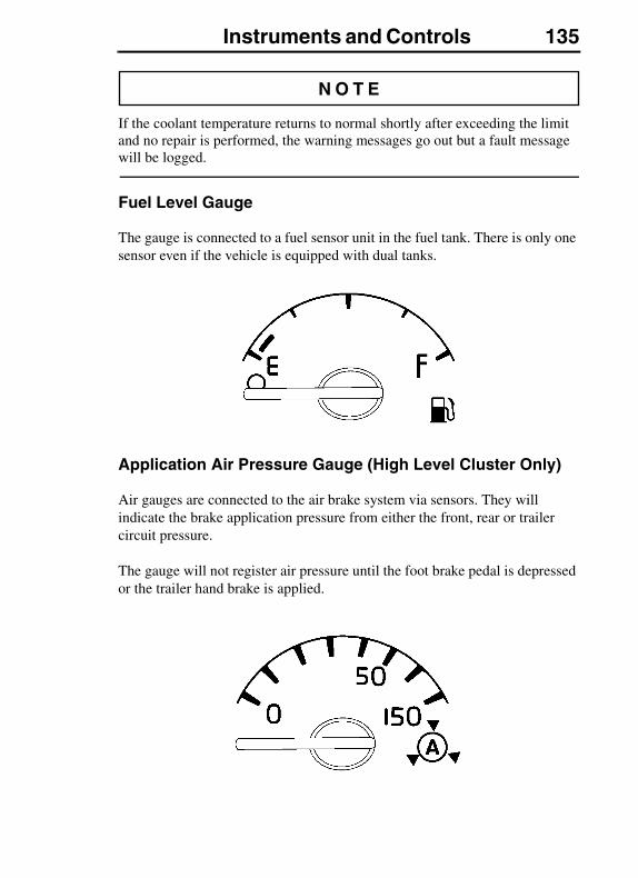
Instruments and Controls 135
If the coolant temperature returns to normal shortly after exceeding the limit and no repair is performed, the warning messages go out but a fault message will be logged.
Fuel Level Gauge
The gauge is connected to a fuel sensor unit in the fuel tank. There is only one sensor even if the vehicle is equipped with dual tanks.
Application Air Pressure Gauge (High Level Cluster Only)
Air gauges are connected to the air brake system via sensors. They will indicate the brake application pressure from either the front, rear or trailer circuit pressure.
The gauge will not register air pressure until the foot brake pedal is depressed or the trailer hand brake is applied.
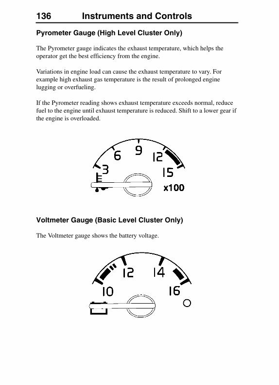
136 Instruments and Controls
Pyrometer Gauge (High Level Cluster Only)
The Pyrometer gauge indicates the exhaust temperature, which helps the operator get the best efficiency from the engine.
Variations in engine load can cause the exhaust temperature to vary. For example high exhaust gas temperature is the result of prolonged engine lugging or overfueling.
If the Pyrometer reading shows exhaust temperature exceeds normal, reduce fuel to the engine until exhaust temperature is reduced. Shift to a lower gear if the engine is overloaded.
Voltmeter Gauge (Basic Level Cluster Only)
The Voltmeter gauge shows the battery voltage.
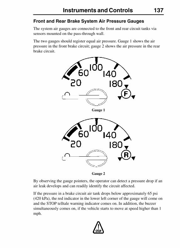
Instruments and Controls 137
Front and Rear Brake System Air Pressure Gauges
The system air gauges are connected to the front and rear circuit tanks via sensors mounted on the pass-through wall.
The two gauges should register equal air pressure. Gauge 1 shows the air pressure in the front brake circuit; gauge 2 shows the air pressure in the rear brake circuit.
Gauge 1
Gauge 2
By observing the gauge pointers, the operator can detect a pressure drop if an air leak develops and can readily identify the circuit affected.
If the pressure in a brake circuit air tank drops below approximately 65 psi (420 kPa), the red indicator in the lower left corner of the gauge will come on and the STOP telltale warning indicator comes on. In addition, the buzzer simultaneously comes on, if the vehicle starts to move at speed higher than 1 mph.

138 Instruments and Controls
If the air pressure is allowed to drop below 65 psi (420 kPa) in both systems, the “mechanical” brakes will automatically engage to stop the vehicle.
The STOP telltale warning, solid red LED light, and buzzer are simultaneously present when the engine is ON and the vehicle is in motion. There is no buzzer if the vehicle is idle/stationary. If the vehicle is idle, only the STOP telltale warning and solid red LED light appear.
Failure to observe these precautions can result in the loss of braking performance. This can lead to vehicle accident, which can result in personal injury or death.
Secondary Gauge
The Secondary Gauge is an optional feature, which is available only with the Mid and High instrument clusters. The instrument cluster receives temperature information from the datalink then passes the information to the Secondary gauge for viewing.
1. Secondary gauge
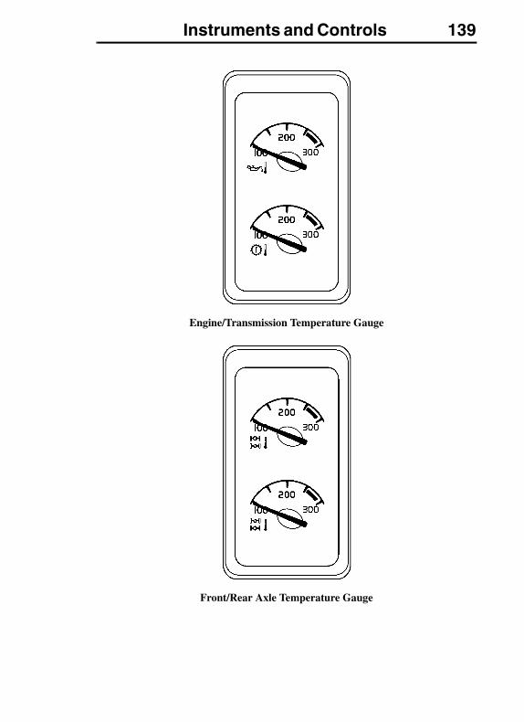
Instruments and Controls 139
Engine/Transmission Temperature Gauge
Front/Rear Axle Temperature Gauge
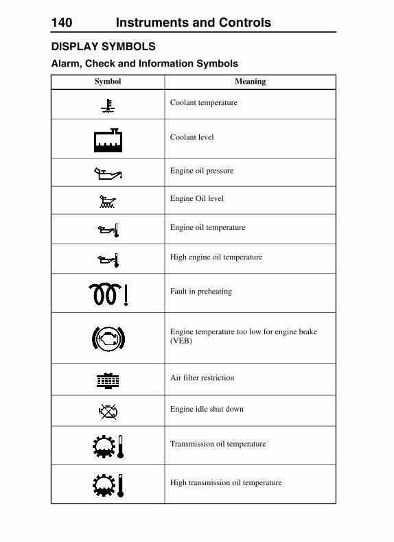
140 Instruments and Controls
DISPLAY SYMBOLS
Alarm, Check and Information Symbols
Symbol Meaning
Coolant temperature
Coolant level
Engine oil pressure
Engine Oil level
Engine oil temperature
High engine oil temperature
Fault in preheating
Engine temperature too low for engine brake (VEB)
Air filter restriction
Engine idle shut down
Transmission oil temperature
High transmission oil temperature
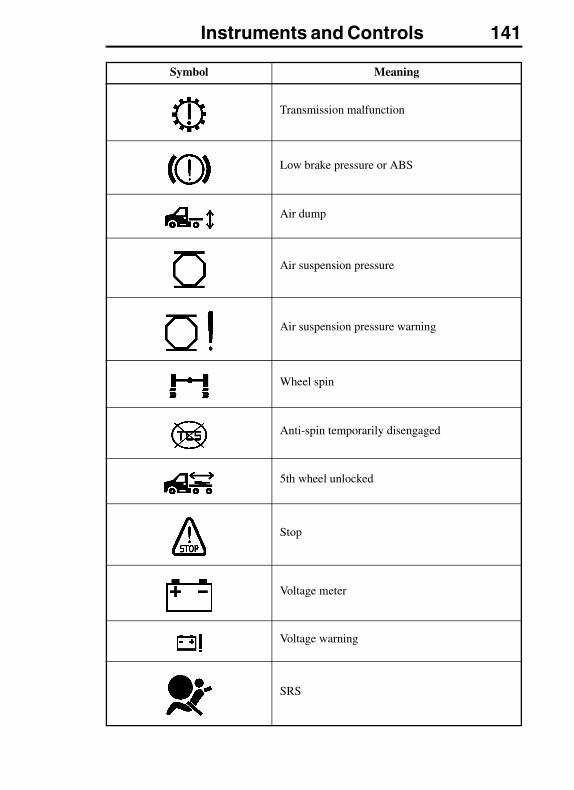
Instruments and Controls 141
Transmission malfunction
Low brake pressure or ABS
Air dump
Air suspension pressure
Air suspension pressure warning
Wheel spin
Anti-spin temporarily disengaged
5th wheel unlocked
Stop
Voltage meter
Voltage warning
SRS
Symbol Meaning
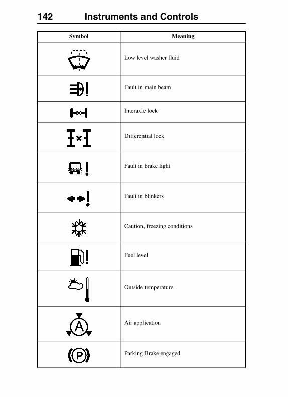
142 Instruments and Controls
Low level washer fluid
Fault in main beam
Interaxle lock
Differential lock
Fault in brake light
Fault in blinkers
Caution, freezing conditions
Fuel level
Outside temperature
Air application
Parking Brake engaged
Symbol Meaning

Instruments and Controls 143
Axle Temperature
Engine speed
Intake manifold pressure
Instantaneous/average fuel economy (liters/100km)
Instantaneous/average fuel economy (km/liter)
Instantaneous/average fuel economy (mpg)
Instantaneous/average fuel economy (liters/hour)
Leg fuel (liter)
Leg fuel (gallon)
Trip data (km)
Trip data (miles)
Average speed (km/h)
Average speed (mph)
Symbol Meaning
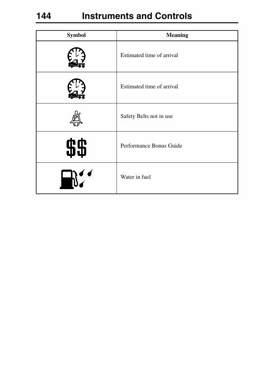
144 Instruments and Controls
Estimated time of arrival
Estimated time of arrival
Safety Belts not in use
Performance Bonus Guide
Water in fuel
Symbol Meaning
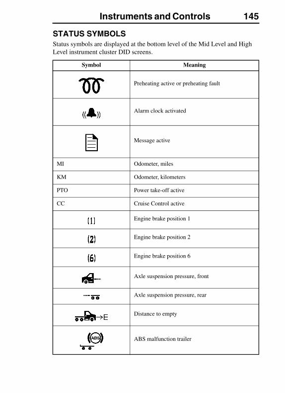
Instruments and Controls 145
STATUS SYMBOLSStatus symbols are displayed at the bottom level of the Mid Level and High Level instrument cluster DID screens.
Symbol Meaning
Preheating active or preheating fault
Alarm clock activated
Message active
MI Odometer, miles
KM Odometer, kilometers
PTO Power take-off active
CC Cruise Control active
Engine brake position 1
Engine brake position 2
Engine brake position 6
Axle suspension pressure, front
Axle suspension pressure, rear
Distance to empty
ABS malfunction trailer
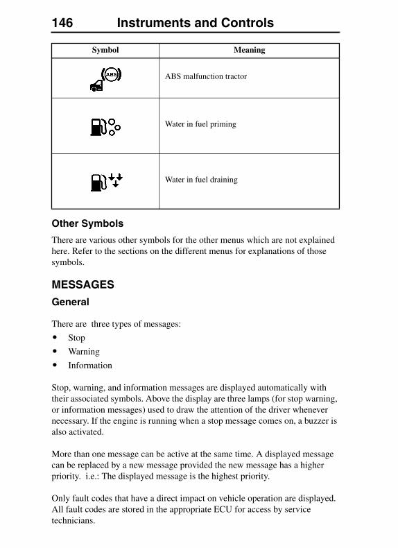
146 Instruments and Controls
Other Symbols
There are various other symbols for the other menus which are not explained here. Refer to the sections on the different menus for explanations of those symbols.
MESSAGES
General
There are three types of messages:
� Stop
� Warning
� Information
Stop, warning, and information messages are displayed automatically with their associated symbols. Above the display are three lamps (for stop warning, or information messages) used to draw the attention of the driver whenever necessary. If the engine is running when a stop message comes on, a buzzer is also activated.
More than one message can be active at the same time. A displayed message can be replaced by a new message provided the new message has a higher priority. i.e.: The displayed message is the highest priority.
Only fault codes that have a direct impact on vehicle operation are displayed. All fault codes are stored in the appropriate ECU for access by service technicians.
ABS malfunction tractor
Water in fuel priming
Water in fuel draining
Symbol Meaning
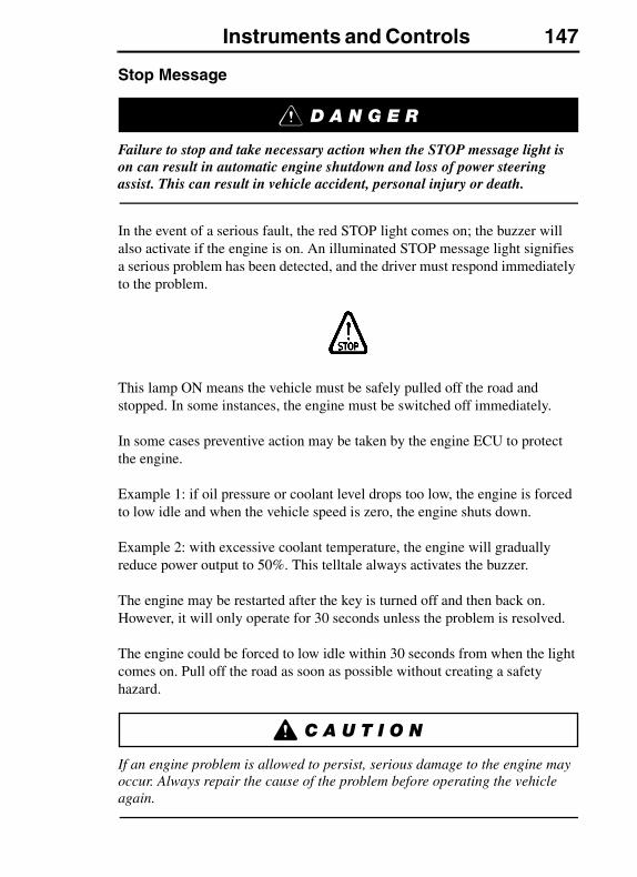
Instruments and Controls 147
Stop Message
Failure to stop and take necessary action when the STOP message light is on can result in automatic engine shutdown and loss of power steering assist. This can result in vehicle accident, personal injury or death.
In the event of a serious fault, the red STOP light comes on; the buzzer will also activate if the engine is on. An illuminated STOP message light signifies a serious problem has been detected, and the driver must respond immediately to the problem.
This lamp ON means the vehicle must be safely pulled off the road and stopped. In some instances, the engine must be switched off immediately.
In some cases preventive action may be taken by the engine ECU to protect the engine.
Example 1: if oil pressure or coolant level drops too low, the engine is forced to low idle and when the vehicle speed is zero, the engine shuts down.
Example 2: with excessive coolant temperature, the engine will gradually reduce power output to 50%. This telltale always activates the buzzer.
The engine may be restarted after the key is turned off and then back on. However, it will only operate for 30 seconds unless the problem is resolved.
The engine could be forced to low idle within 30 seconds from when the light comes on. Pull off the road as soon as possible without creating a safety hazard.
If an engine problem is allowed to persist, serious damage to the engine may occur. Always repair the cause of the problem before operating the vehicle again.
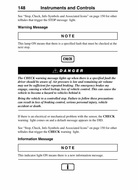
148 Instruments and Controls
See “Stop, Check, Info Symbols and Associated Icons” on page 150 for other telltales that trigger the STOP message light.
Warning Message
This lamp ON means that there is a specified fault that must be checked at the next stop.
The CHECK warning message lights up when there is a specified fault the driver should be aware of. Air pressure is low and remaining air volume may not be sufficient for repeated braking. The emergency brakes my engage, causing a wheel lockup, loss of vehicle control. This can cause the vehicle to become a hazard to vehicles behind it.
Bring the vehicle to a controlled stop. Failure to follow these precautions can result in loss of braking control, serious personal injury, vehicle accident or death.
If there is an electrical or mechanical problem with the sensor, the CHECK warning light comes on and a default message appears in the DID.
See “Stop, Check, Info Symbols and Associated Icons” on page 150 for other telltales that trigger the CHECK warning light.
Information Message
This indicator light ON means there is a new information message.
Instruments and Controls 149
The INFO indicator light comes on when there is a new information message or an abnormal status is detected by the electronic control unit. A telltale, text or both are shown in the DID in addition to the INFO light. For certain telltales, a reference value is also shown.
Make sure the indicated fault is checked at the next stop once the INFO indicator come on.
See “Stop, Check, Info Symbols and Associated Icons” on page 150 for other telltales that trigger the INFO indicator.
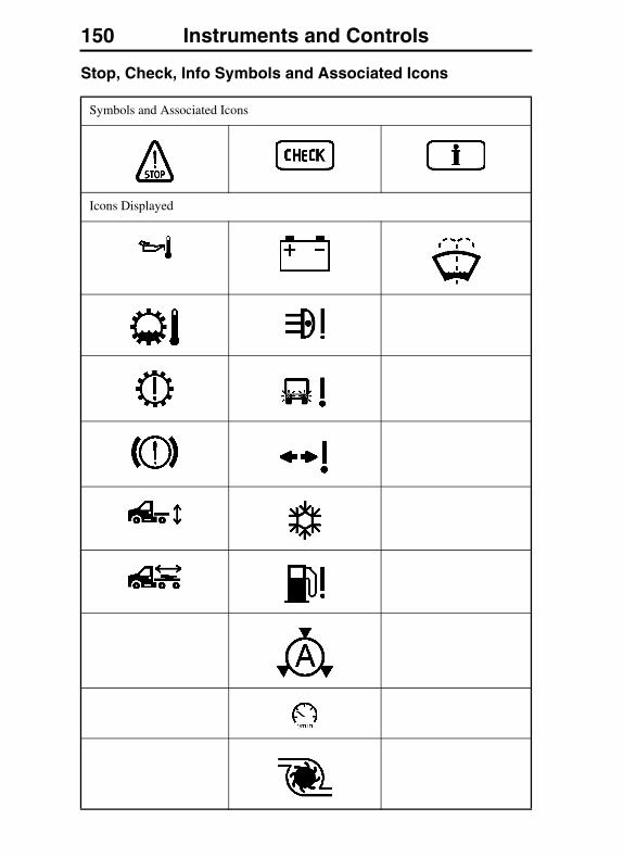
150 Instruments and Controls
Stop, Check, Info Symbols and Associated Icons
Symbols and Associated Icons
Icons Displayed
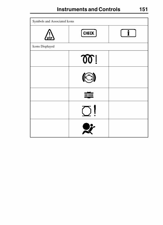
Instruments and Controls 151
Symbols and Associated Icons
Icons Displayed
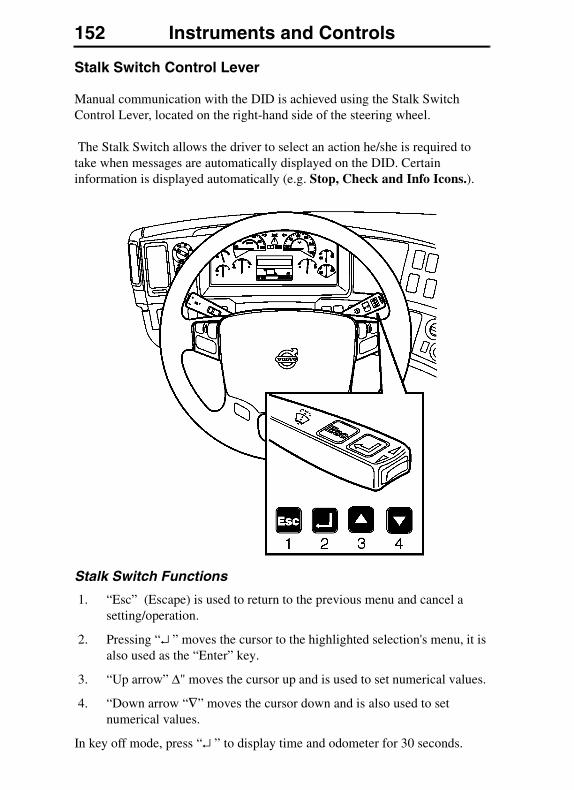
152 Instruments and Controls
Stalk Switch Control Lever
Manual communication with the DID is achieved using the Stalk Switch Control Lever, located on the right-hand side of the steering wheel.
The Stalk Switch allows the driver to select an action he/she is required to take when messages are automatically displayed on the DID. Certain information is displayed automatically (e.g. Stop, Check and Info Icons.).
Stalk Switch Functions
1. “Esc” (Escape) is used to return to the previous menu and cancel a setting/operation.
2. Pressing “↵ ” moves the cursor to the highlighted selection's menu, it is also used as the “Enter” key.
3. “Up arrow” Δ" moves the cursor up and is used to set numerical values.
4. “Down arrow “∇” moves the cursor down and is also used to set numerical values.
In key off mode, press “↵ ” to display time and odometer for 30 seconds.
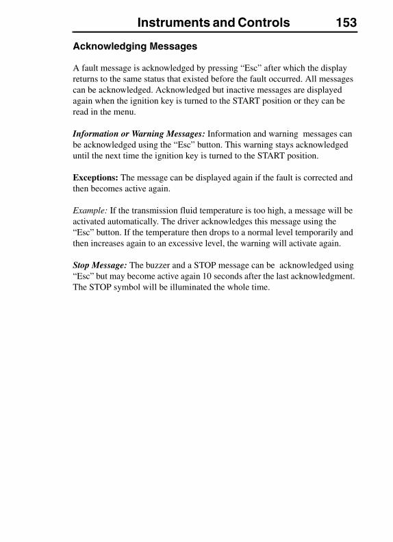
Instruments and Controls 153
Acknowledging Messages
A fault message is acknowledged by pressing “Esc” after which the display returns to the same status that existed before the fault occurred. All messages can be acknowledged. Acknowledged but inactive messages are displayed again when the ignition key is turned to the START position or they can be read in the menu.
Information or Warning Messages: Information and warning messages can be acknowledged using the “Esc” button. This warning stays acknowledged until the next time the ignition key is turned to the START position.
Exceptions: The message can be displayed again if the fault is corrected and then becomes active again.
Example: If the transmission fluid temperature is too high, a message will be activated automatically. The driver acknowledges this message using the “Esc” button. If the temperature then drops to a normal level temporarily and then increases again to an excessive level, the warning will activate again.
Stop Message: The buzzer and a STOP message can be acknowledged using “Esc” but may become active again 10 seconds after the last acknowledgment. The STOP symbol will be illuminated the whole time.

154 Instruments and Controls
Examples of Fault Symbols and Text
Factory–Installed Equipment When Stationary
The Stop, warning, or info symbol comes on and the information message is shown on the display (for more information on the fault, see “1. Fault Diagnostics” on page 200). A warning tone will be heard if the engine is running when a stop message is activated. The message contains information about the location of the fault where the fault has occurred:
Non-Factory-Installed Equipment
If a coach builder or customer has retrofitted equipment that is connected to the data link, the following symbols may be displayed:
MID (Message IDentifier) = control unit
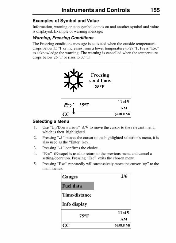
Instruments and Controls 155
Examples of Symbol and ValueInformation, warning or stop symbol comes on and another symbol and value is displayed. Example of warning message:
Warning, Freezing ConditionsThe Freezing conditions message is activated when the outside temperature drops below 35 °F or increases from a lower temperature to 28 °F. Press “Esc” to acknowledge the warning. The warning is cancelled when the temperature drops below 26 °F or rises to 37 °F.
Selecting a Menu1. Use “Up/Down arrow” Δ/∇ to move the cursor to the relevant menu,
which is then highlighted.
2. Pressing “↵ ” moves the cursor to the highlighted selection's menu, it is also used as the “Enter” key.
3. Pressing “↵ ” confirms the choice.
4. “Esc” (Escape) is used to return to the previous menu and cancel a setting/operation. Pressing “Esc” exits the chosen menu.
5. Pressing “Esc” repeatedly will successively move the cursor “up” to the main menus.
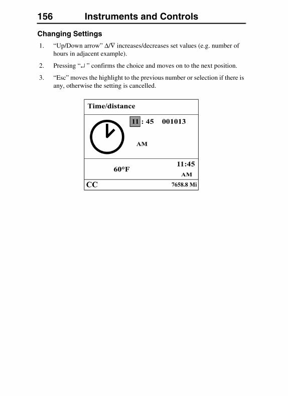
156 Instruments and Controls
Changing Settings
1. “Up/Down arrow” Δ/∇ increases/decreases set values (e.g. number of hours in adjacent example).
2. Pressing “↵ ” confirms the choice and moves on to the next position.
3. “Esc” moves the highlight to the previous number or selection if there is any, otherwise the setting is cancelled.
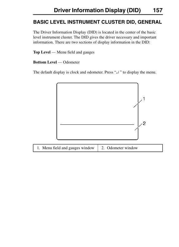
Driver Information Display (DID) 157DRIVER INFORMATION DISPLAY (DID)
BASIC LEVEL INSTRUMENT CLUSTER DID, GENERAL
The Driver Information Display (DID) is located in the center of the basic level instrument cluster. The DID gives the driver necessary and important information. There are two sections of display information in the DID:
Top Level — Menu field and gauges
Bottom Level — Odometer
The default display is clock and odometer. Press “↵ ” to display the menu.
1. Menu field and gauges window 2. Odometer window
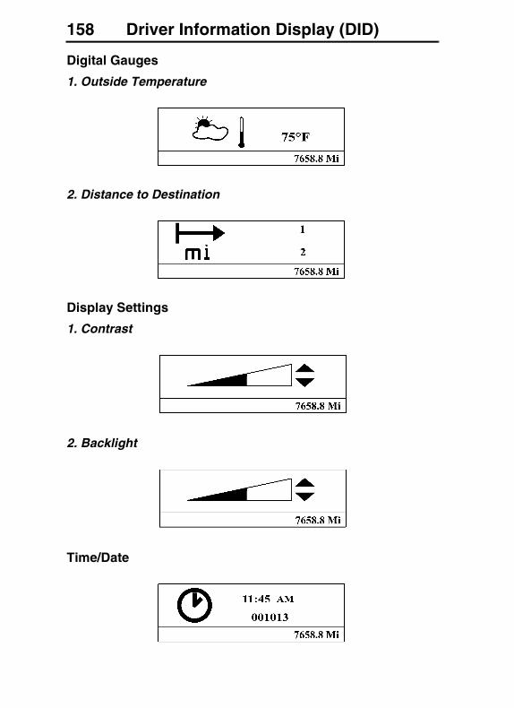
158 Driver Information Display (DID)
Digital Gauges
1. Outside Temperature
2. Distance to Destination
Display Settings
1. Contrast
2. Backlight
Time/Date

Driver Information Display (DID) 159
Setup
1. Language
2. Distance
3. Temperature
MID-LEVEL AND HIGH-LEVEL INSTRUMENT CLUSTER DID, GENERALThe Driver Information Display (DID) is located in the center of the mid-level and high-level instrument clusters. It contains numerous main menus and sub-menus with their associated functions.
The information available to the driver depends on vehicle configuration, and whether the vehicle is stationary or in operation. Certain functions are password-protected and are not shown until the correct password is entered.
The DID gives the driver necessary and important information. There are three sections of display information in the DID:
Top Level — Menu field
Middle Level — Favorite Display
Bottom Level — Status Bar and Odometer
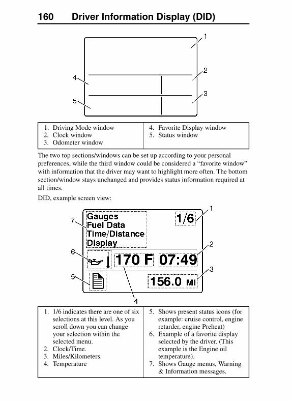
160 Driver Information Display (DID)
The two top sections/windows can be set up according to your personal preferences, while the third window could be considered a “favorite window” with information that the driver may want to highlight more often. The bottom section/window stays unchanged and provides status information required at all times.
DID, example screen view:
1. Driving Mode window2. Clock window3. Odometer window
4. Favorite Display window5. Status window
1. 1/6 indicates there are one of six selections at this level. As you scroll down you can change your selection within the selected menu.
2. Clock/Time.3. Miles/Kilometers.4. Temperature
5. Shows present status icons (for example: cruise control, engine retarder, engine Preheat)
6. Example of a favorite display selected by the driver. (This example is the Engine oil temperature).
7. Shows Gauge menus, Warning & Information messages.

Driver Information Display (DID) 161
MID-LEVEL AND HIGH-LEVEL DID MENUThe Driver Information Display screen (DID) has up to 13 main menus. There is a Driving and a Non-Driving menu. Several sub-menus are password-protected while the vehicle is stationary. The Non-Driving menu is accessible only when the vehicle is stationary (parked).
In order to view all menus at the same time, the correct password must be given. This applies every time the ignition is turned ON and the vehicle is placed in the drive position. See “Password” on page 213.
Driving Menu� Volvo Link (optional)
— Read Message
— Send Message
— Satellite Link Status
� Gauges
— Current Gear Position (Automated Transmission)
— Outside Temperature
— Temperature Engine Oil
— Temperature Transmission
— Battery Voltage
— Axle Temperature (Front/Rear)
— Air Suspension (Front/Rear)
— Volvo Link Compass
� Fuel Data
— Instantaneous Gallons per Hour
— Trip Fuel Used
— Distance to Empty
— Fuel Economy
— Idle Percent
— Sweet Spot/Performance Bonus
— Sweet Spot Trip Data Percentage
— Sweet Spot Total Data Percentage
— Road Speed Limit
162 Driver Information Display (DID)
� Time/Distance
— Time and Date
— Alarm Clock
— Distance to Destination
— Average Trip Speed
— Estimated Time of Arrival (ETA)
� Display
— Black Panel
— Favorite Display
— Backlight
— Favorite Display Setting
— Night/Day
� Vehicle Messages
� Reset
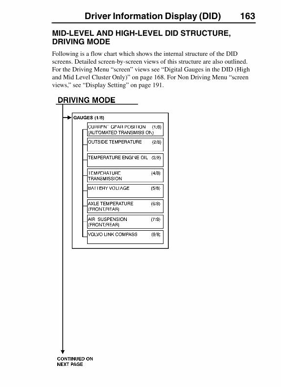
Driver Information Display (DID) 163
MID-LEVEL AND HIGH-LEVEL DID STRUCTURE, DRIVING MODEFollowing is a flow chart which shows the internal structure of the DID screens. Detailed screen-by-screen views of this structure are also outlined. For the Driving Menu “screen” views see “Digital Gauges in the DID (High and Mid Level Cluster Only)” on page 168. For Non Driving Menu “screen views,” see “Display Setting” on page 191.

164 Driver Information Display (DID)

Driver Information Display (DID) 165

166 Driver Information Display (DID)
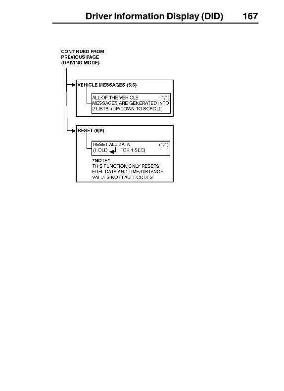
Driver Information Display (DID) 167
168 Driver Information Display (DID)
Digital Gauges in the DID (High and Mid Level Cluster Only)
There are several gauges in the “Gauges” menu. The number of gauges your vehicle is programmed with depends on the equipment level of the vehicle. The gauges are used to view current status of important functions in the vehicle.
All gauges are programmed into the Instrument Cluster and are therefore visible only in the DID.
Eaton Autoshift equipped vehicles always have transmission/gear position displayed at the bottom of the favorites display screen.
� Current Gear Position (Automated Transmission)
� Outside Temperature
� Temperature, Engine Oil
� Temperature, Transmission
� Battery Voltage
� Axle Temperature (Front/Rear)
� Pressure Automatic Suspension (Front/Rear)
� Volvo Link Compass
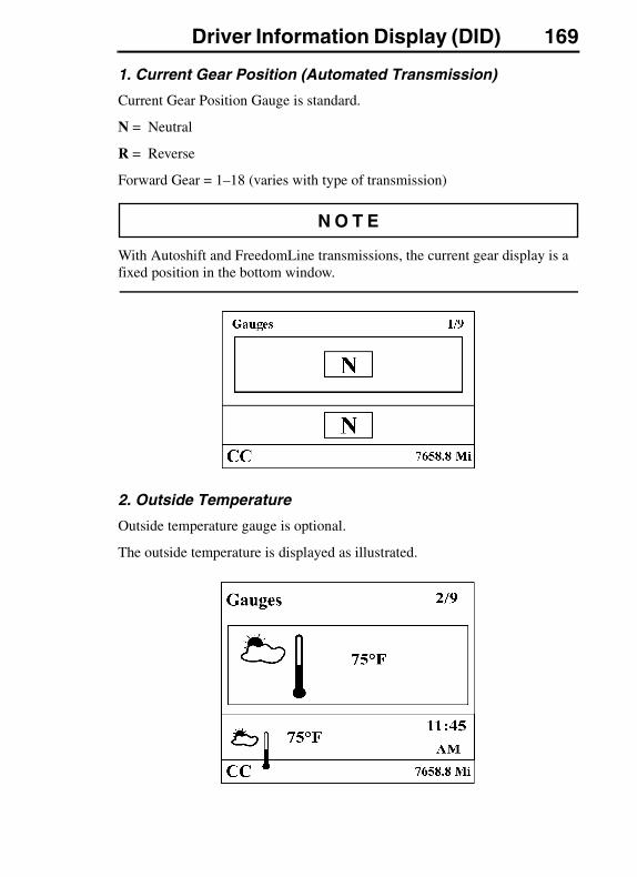
Driver Information Display (DID) 169
1. Current Gear Position (Automated Transmission)
Current Gear Position Gauge is standard.
N = Neutral
R = Reverse
Forward Gear = 1–18 (varies with type of transmission)
With Autoshift and FreedomLine transmissions, the current gear display is a fixed position in the bottom window.
2. Outside Temperature
Outside temperature gauge is optional.
The outside temperature is displayed as illustrated.

170 Driver Information Display (DID)
3. Temperature, Engine Oil
The engine oil temperature is displayed as illustrated.
4. Temperature, Transmission Oil
5. Battery Voltage
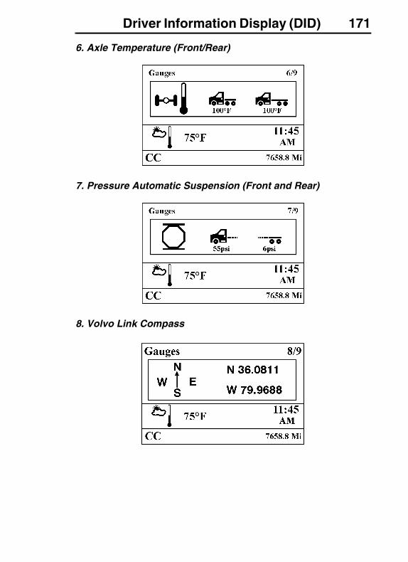
Driver Information Display (DID) 171
6. Axle Temperature (Front/Rear)
7. Pressure Automatic Suspension (Front and Rear)
8. Volvo Link Compass
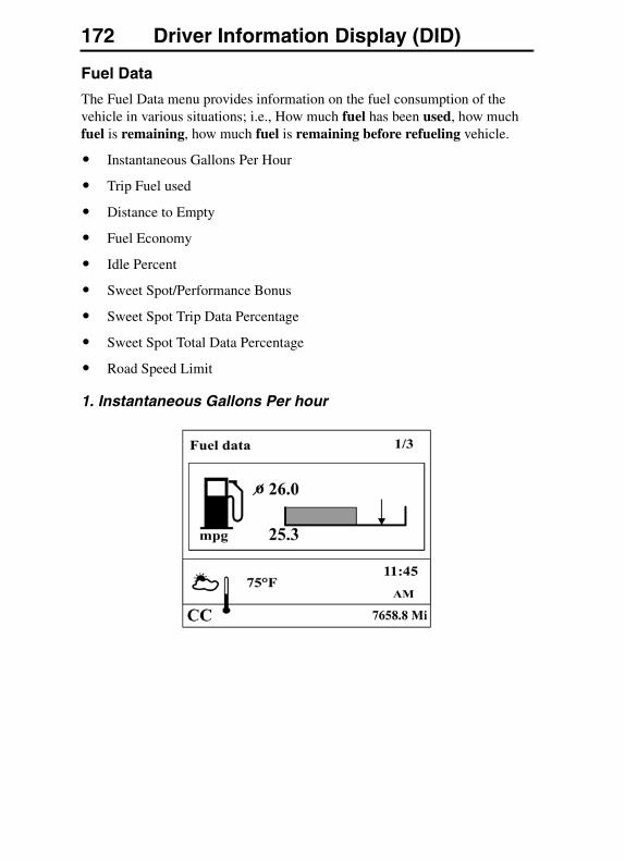
172 Driver Information Display (DID)
Fuel Data
The Fuel Data menu provides information on the fuel consumption of the vehicle in various situations; i.e., How much fuel has been used, how much fuel is remaining, how much fuel is remaining before refueling vehicle.
� Instantaneous Gallons Per Hour
� Trip Fuel used
� Distance to Empty
� Fuel Economy
� Idle Percent
� Sweet Spot/Performance Bonus
� Sweet Spot Trip Data Percentage
� Sweet Spot Total Data Percentage
� Road Speed Limit
1. Instantaneous Gallons Per hour
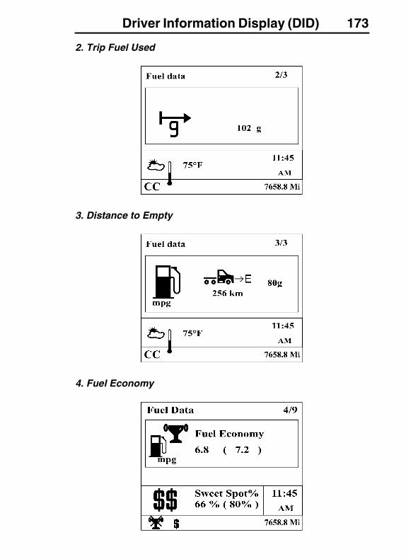
Driver Information Display (DID) 173
2. Trip Fuel Used
3. Distance to Empty
4. Fuel Economy

174 Driver Information Display (DID)
5. Idle Percent
6. Sweet Spot/Performance Bonus
7. Sweet Spot Trip Data Percentage
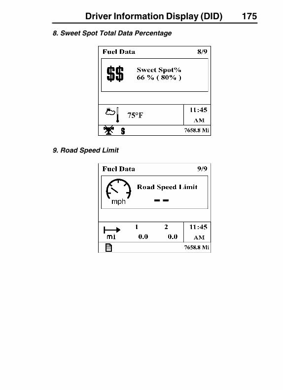
Driver Information Display (DID) 175
8. Sweet Spot Total Data Percentage
9. Road Speed Limit
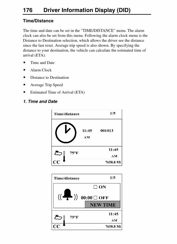
176 Driver Information Display (DID)
Time/Distance
The time and date can be set in the "TIME/DISTANCE" menu. The alarm clock can also be set from this menu. Following the alarm clock menu is the Distance to Destination selection, which allows the driver see the distance since the last reset. Average trip speed is also shown. By specifying the distance to your destination, the vehicle can calculate the estimated time of arrival (ETA).
� Time and Date
� Alarm Clock
� Distance to Destination
� Average Trip Speed
� Estimated Time of Arrival (ETA)
1. Time and Date
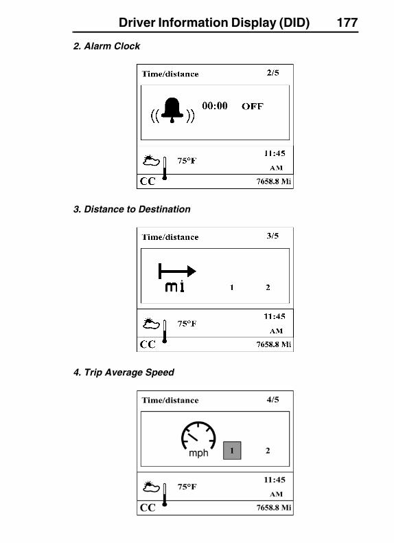
Driver Information Display (DID) 177
2. Alarm Clock
3. Distance to Destination
4. Trip Average Speed
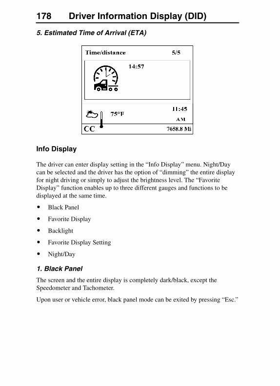
178 Driver Information Display (DID)
5. Estimated Time of Arrival (ETA)
Info Display
The driver can enter display setting in the “Info Display” menu. Night/Day can be selected and the driver has the option of “dimming” the entire display for night driving or simply to adjust the brightness level. The “Favorite Display” function enables up to three different gauges and functions to be displayed at the same time.
� Black Panel
� Favorite Display
� Backlight
� Favorite Display Setting
� Night/Day
1. Black Panel
The screen and the entire display is completely dark/black, except the Speedometer and Tachometer.
Upon user or vehicle error, black panel mode can be exited by pressing “Esc.”
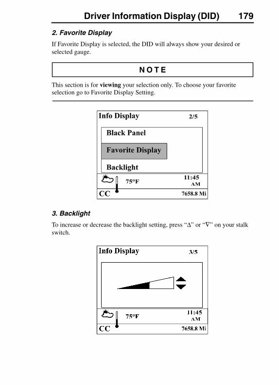
Driver Information Display (DID) 179
2. Favorite Display
If Favorite Display is selected, the DID will always show your desired or selected gauge.
This section is for viewing your selection only. To choose your favorite selection go to Favorite Display Setting.
3. Backlight
To increase or decrease the backlight setting, press “Δ” or “∇” on your stalk switch.
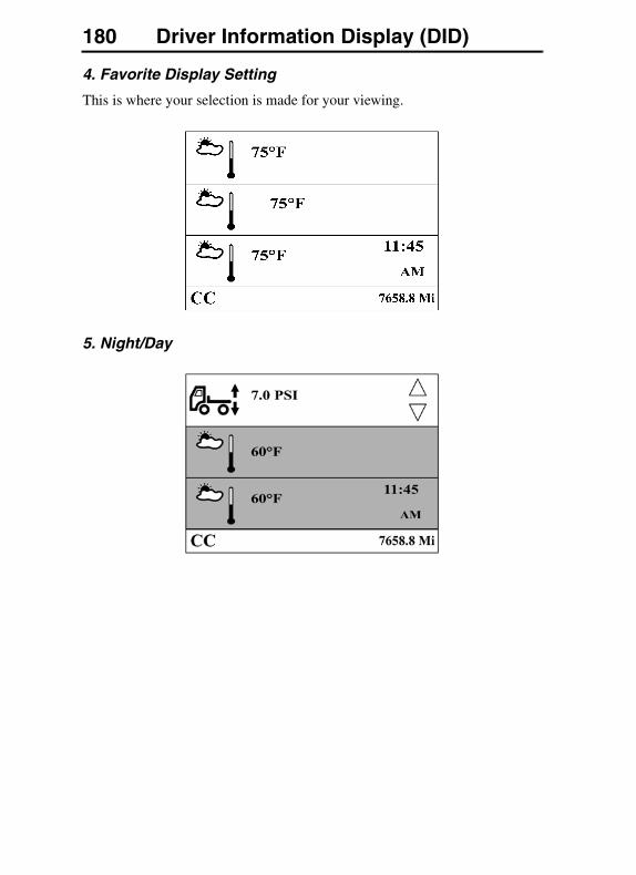
180 Driver Information Display (DID)
4. Favorite Display Setting
This is where your selection is made for your viewing.
5. Night/Day

Driver Information Display (DID) 181
Vehicle Messages
Vehicle Messages appear in the DID depending on the number of faults the vehicle has at any given time.
If there are no messages:
Reset
Pressing and holding down the “↵ ” button for more than 1 second resets the following functions:
Instantaneous Gallons per hour
Trip Fuel used
Distance to empty
� Reset
182 Driver Information Display (DID)
MID-LEVEL AND HIGH-LEVEL DID STRUCTURE, NON-DRIVING MODE
Non-Driving Menu
� Display Setting
— Language
— Units
— Time/Date
— Display Light
— Change Password
� Vehicle Settings (Volvo Engines Only)
— Fleet Limits
— Fleet ID
— Water in Fuel
� Diagnostics
— Fault Diagnostics
— Cluster Self Test
— Part Number
� Vehicle Data (Volvo Engines Only)
— Oil Level
� Data Log
— Vehicle ID
— Sweet Spot Data
— Total Data
— Trip Data
— Reset Trip Data
� Password
� Enter Password
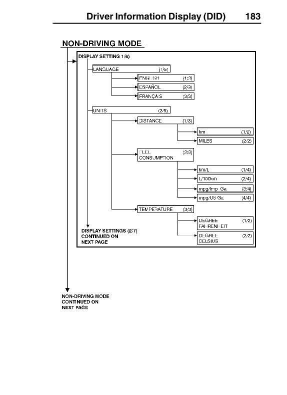
Driver Information Display (DID) 183
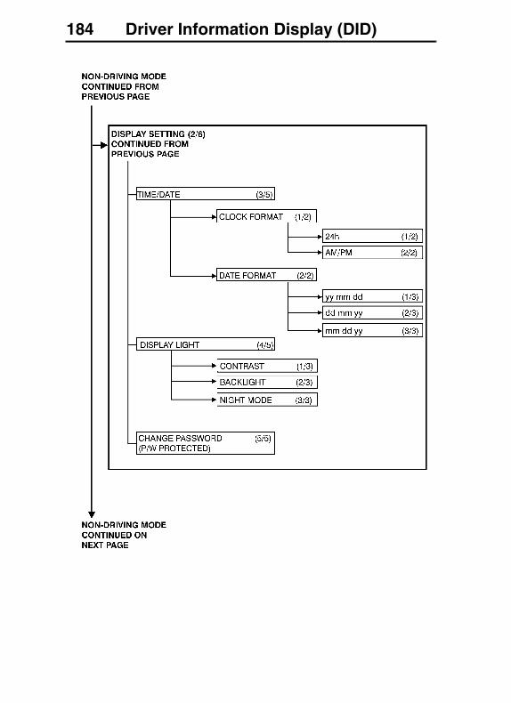
184 Driver Information Display (DID)
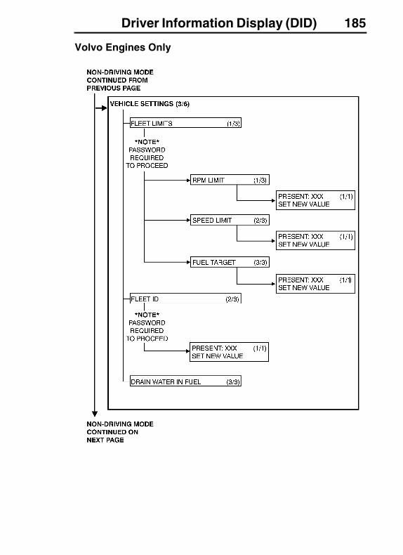
Driver Information Display (DID) 185
Volvo Engines Only

186 Driver Information Display (DID)
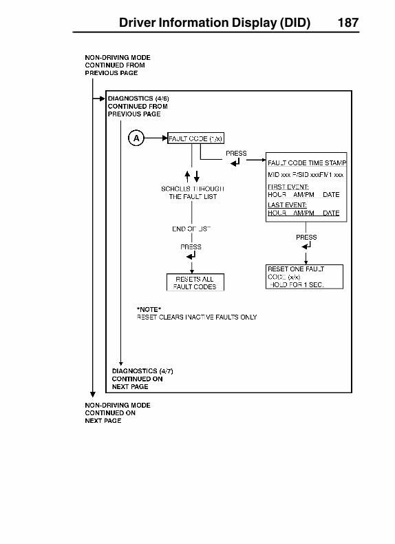
Driver Information Display (DID) 187

188 Driver Information Display (DID)
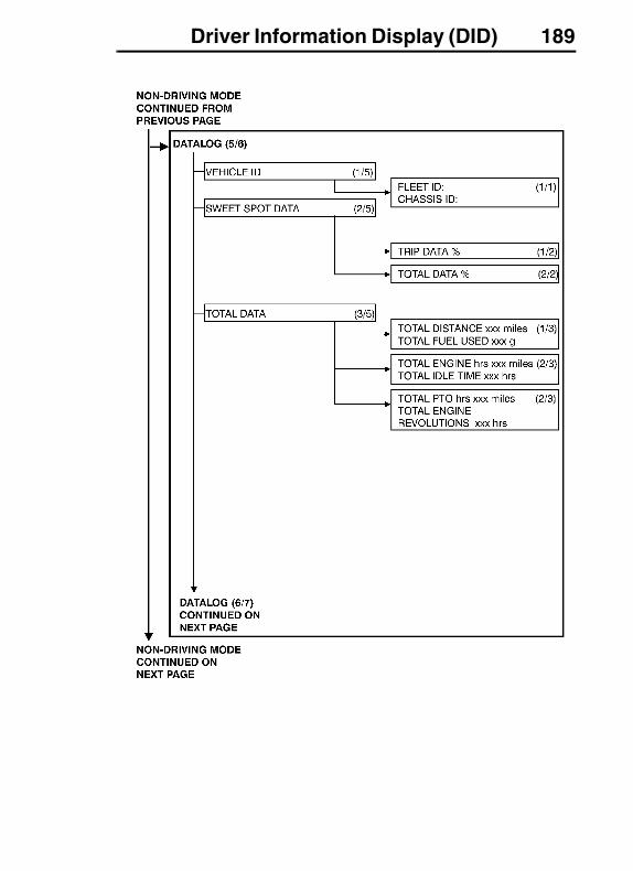
Driver Information Display (DID) 189
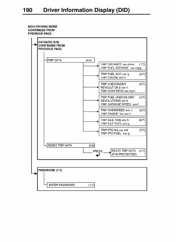
190 Driver Information Display (DID)

Driver Information Display (DID) 191
Display Setting
The display Setting menu is used to change between languages. The time and date can be changed here also.
� Language
� Units
� Time/Date
� Display/Adjust
� Change Password
� Password protected menu
1. Language
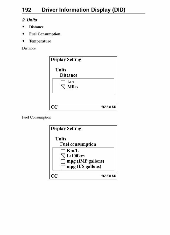
192 Driver Information Display (DID)
2. Units
� Distance
� Fuel Consumption
� Temperature
Distance
Fuel Consumption
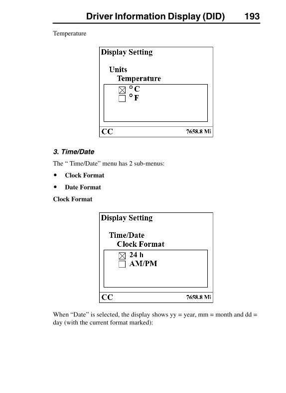
Driver Information Display (DID) 193
Temperature
3. Time/Date
The “ Time/Date” menu has 2 sub-menus:
� Clock Format
� Date Format
Clock Format
When “Date” is selected, the display shows yy = year, mm = month and dd = day (with the current format marked):
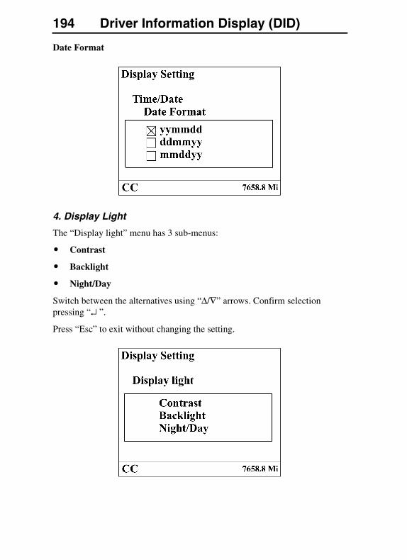
194 Driver Information Display (DID)
Date Format
4. Display Light
The “Display light” menu has 3 sub-menus:
� Contrast
� Backlight
� Night/Day
Switch between the alternatives using “Δ/∇” arrows. Confirm selection pressing “↵ ”.
Press “Esc” to exit without changing the setting.
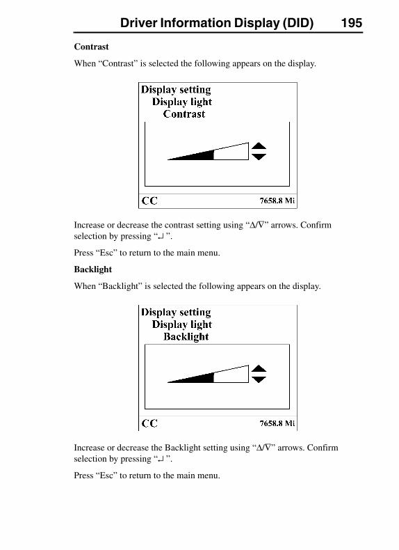
Driver Information Display (DID) 195
Contrast
When “Contrast” is selected the following appears on the display.
Increase or decrease the contrast setting using “Δ/∇” arrows. Confirm selection by pressing “↵ ”.
Press “Esc” to return to the main menu.
Backlight
When “Backlight” is selected the following appears on the display.
Increase or decrease the Backlight setting using “Δ/∇” arrows. Confirm selection by pressing “↵ ”.
Press “Esc” to return to the main menu.
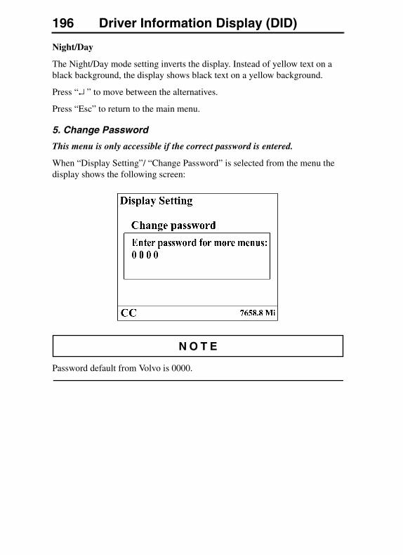
196 Driver Information Display (DID)
Night/Day
The Night/Day mode setting inverts the display. Instead of yellow text on a black background, the display shows black text on a yellow background.
Press “↵ ” to move between the alternatives.
Press “Esc” to return to the main menu.
5. Change Password
This menu is only accessible if the correct password is entered.
When “Display Setting”/ “Change Password” is selected from the menu the display shows the following screen:
Password default from Volvo is 0000.
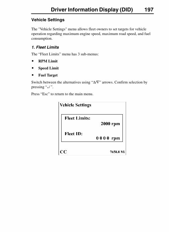
Driver Information Display (DID) 197
Vehicle Settings
The "Vehicle Settings" menu allows fleet owners to set targets for vehicle operation regarding maximum engine speed, maximum road speed, and fuel consumption.
1. Fleet Limits
The “Fleet Limits” menu has 3 sub-menus:
� RPM Limit
� Speed Limit
� Fuel Target
Switch between the alternatives using “Δ/∇” arrows. Confirm selection by pressing “↵ ”.
Press “Esc” to return to the main menu.
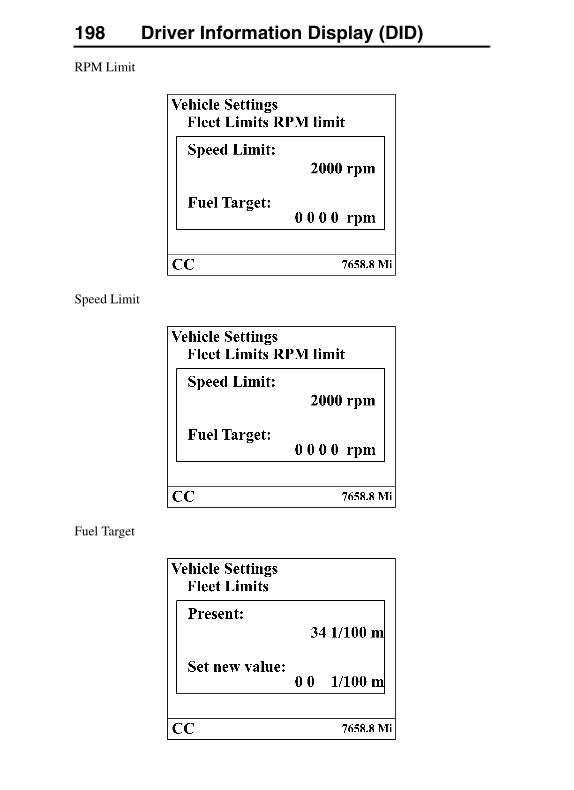
198 Driver Information Display (DID)
RPM Limit
Speed Limit
Fuel Target
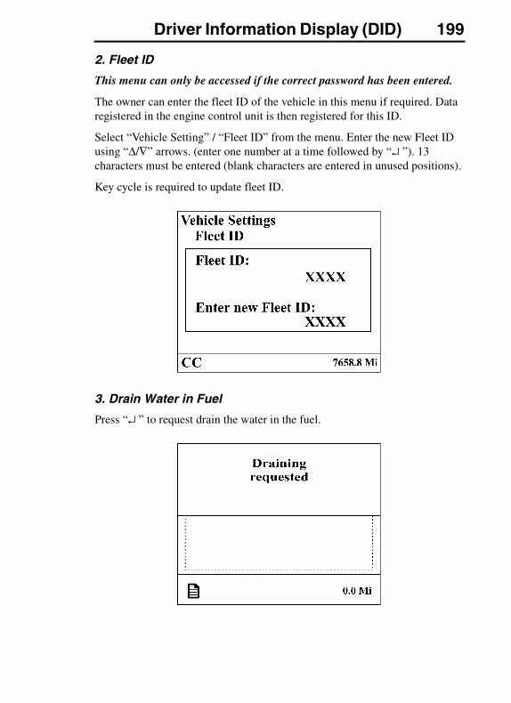
Driver Information Display (DID) 199
2. Fleet ID
This menu can only be accessed if the correct password has been entered.
The owner can enter the fleet ID of the vehicle in this menu if required. Data registered in the engine control unit is then registered for this ID.
Select “Vehicle Setting” / “Fleet ID” from the menu. Enter the new Fleet ID using “Δ/∇” arrows. (enter one number at a time followed by “↵ ”). 13 characters must be entered (blank characters are entered in unused positions).
Key cycle is required to update fleet ID.
3. Drain Water in Fuel
Press “↵ ” to request drain the water in the fuel.
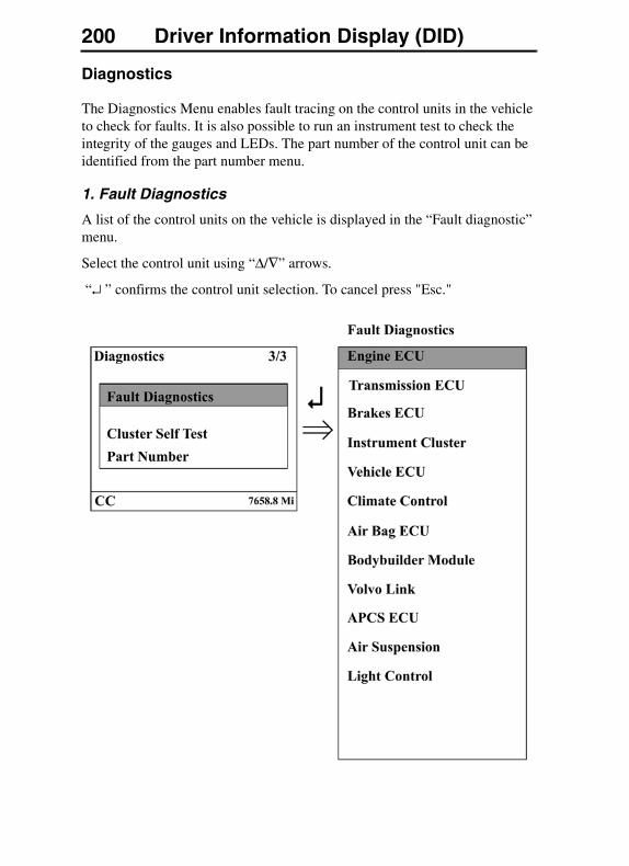
200 Driver Information Display (DID)
Diagnostics
The Diagnostics Menu enables fault tracing on the control units in the vehicle to check for faults. It is also possible to run an instrument test to check the integrity of the gauges and LEDs. The part number of the control unit can be identified from the part number menu.
1. Fault Diagnostics
A list of the control units on the vehicle is displayed in the “Fault diagnostic” menu.
Select the control unit using “Δ/∇” arrows.
“↵ ” confirms the control unit selection. To cancel press "Esc."
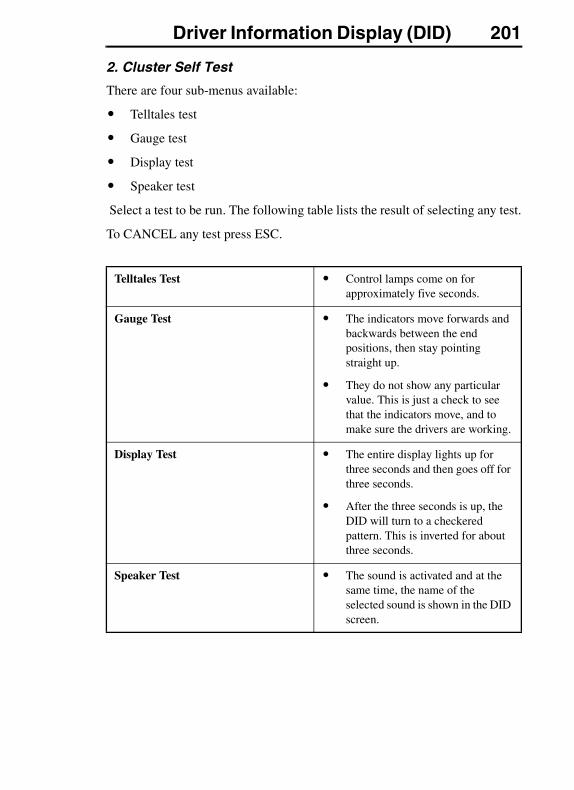
Driver Information Display (DID) 201
2. Cluster Self Test
There are four sub-menus available:
� Telltales test
� Gauge test
� Display test
� Speaker test
Select a test to be run. The following table lists the result of selecting any test.
To CANCEL any test press ESC.
Telltales Test � Control lamps come on for approximately five seconds.
Gauge Test � The indicators move forwards and backwards between the end positions, then stay pointing straight up.
� They do not show any particular value. This is just a check to see that the indicators move, and to make sure the drivers are working.
Display Test � The entire display lights up for three seconds and then goes off for three seconds.
� After the three seconds is up, the DID will turn to a checkered pattern. This is inverted for about three seconds.
Speaker Test � The sound is activated and at the same time, the name of the selected sound is shown in the DID screen.
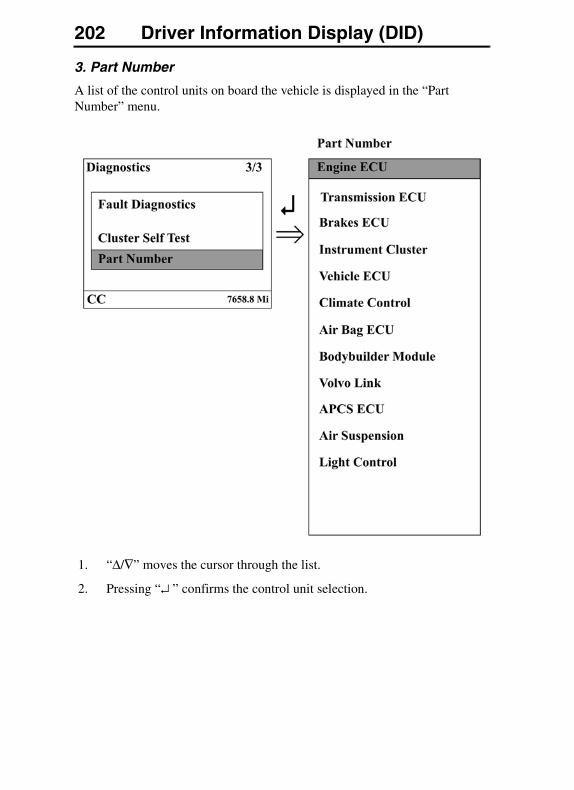
202 Driver Information Display (DID)
3. Part Number
A list of the control units on board the vehicle is displayed in the “Part Number” menu.
1. “Δ/∇” moves the cursor through the list.
2. Pressing “↵ ” confirms the control unit selection.
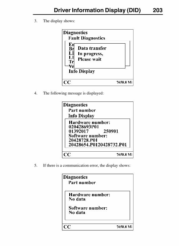
Driver Information Display (DID) 203
3. The display shows:
4. The following message is displayed:
5. If there is a communication error, the display shows:
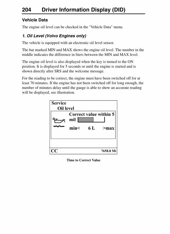
204 Driver Information Display (DID)
Vehicle Data
The engine oil level can be checked in the "Vehicle Data" menu.
1. Oil Level (Volvo Engines only)
The vehicle is equipped with an electronic oil level sensor.
The bar marked MIN and MAX shows the engine oil level. The number in the middle indicates the difference in liters between the MIN and MAX level.
The engine oil level is also displayed when the key is turned to the ON position. It is displayed for 5 seconds or until the engine is started and is shown directly after SRS and the welcome message.
For the reading to be correct, the engine must have been switched off for at least 70 minutes. If the engine has not been switched off for long enough, the number of minutes delay until the gauge is able to show an accurate reading will be displayed, see illustration.
Time to Correct Value
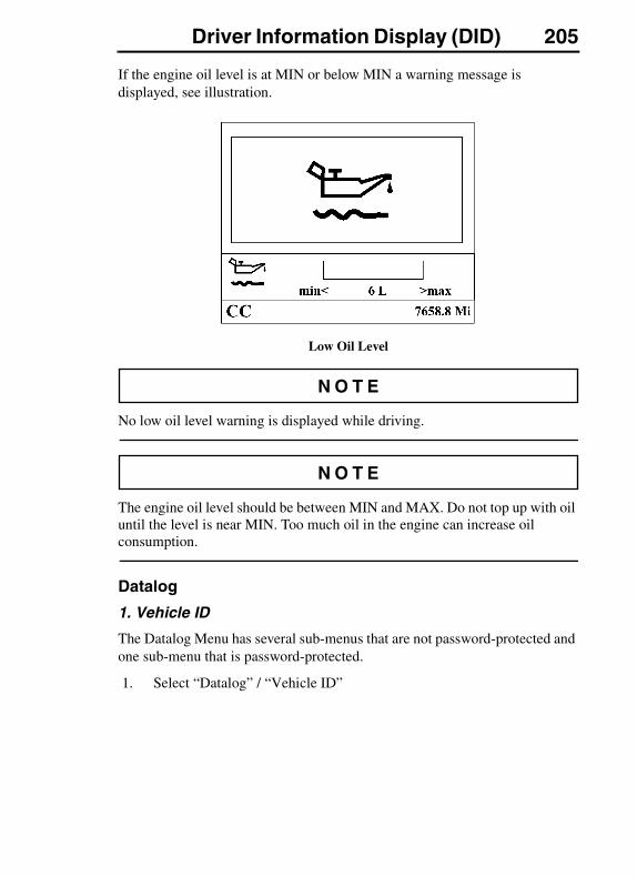
Driver Information Display (DID) 205
If the engine oil level is at MIN or below MIN a warning message is displayed, see illustration.
Low Oil Level
No low oil level warning is displayed while driving.
The engine oil level should be between MIN and MAX. Do not top up with oil until the level is near MIN. Too much oil in the engine can increase oil consumption.
Datalog
1. Vehicle ID
The Datalog Menu has several sub-menus that are not password-protected and one sub-menu that is password-protected.
1. Select “Datalog” / “Vehicle ID”
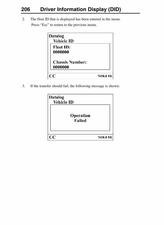
206 Driver Information Display (DID)
2. The fleet ID that is displayed has been entered in the menu.
Press “Esc” to return to the previous menu.
3. If the transfer should fail, the following message is shown:
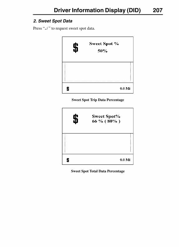
Driver Information Display (DID) 207
2. Sweet Spot Data
Press “↵ ” to request sweet spot data.
Sweet Spot Trip Data Percentage
Sweet Spot Total Data Percentage
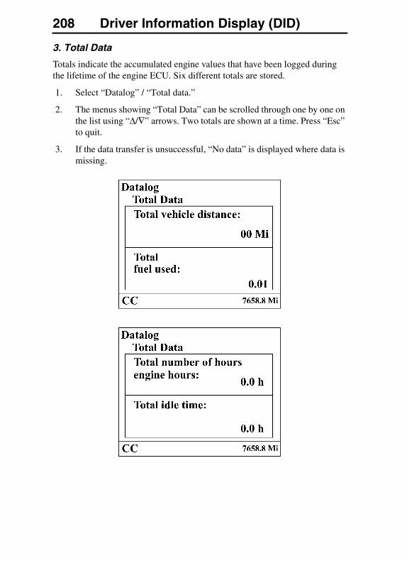
208 Driver Information Display (DID)
3. Total Data
Totals indicate the accumulated engine values that have been logged during the lifetime of the engine ECU. Six different totals are stored.
1. Select “Datalog” / “Total data.”
2. The menus showing “Total Data” can be scrolled through one by one on the list using “Δ/∇” arrows. Two totals are shown at a time. Press “Esc” to quit.
3. If the data transfer is unsuccessful, “No data” is displayed where data is missing.
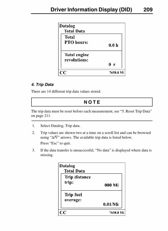
Driver Information Display (DID) 209
4. Trip Data
There are 14 different trip data values stored.
The trip data must be reset before each measurement, see “5. Reset Trip Data” on page 211.
1. Select Datalog, Trip data.
2. Trip values are shown two at a time on a scroll list and can be browsed using “Δ/∇” arrows. The available trip data is listed below.
Press “Esc” to quit.
3. If the data transfer is unsuccessful, “No data” is displayed where data is missing.
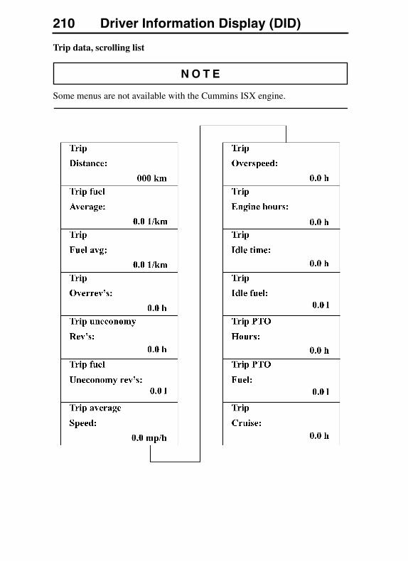
210 Driver Information Display (DID)
Trip data, scrolling list
Some menus are not available with the Cummins ISX engine.
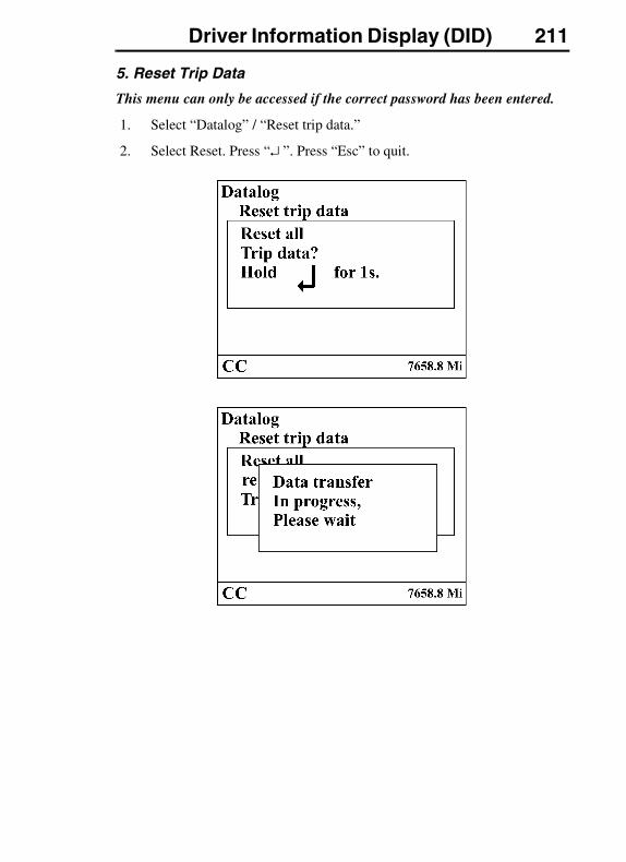
Driver Information Display (DID) 211
5. Reset Trip Data
This menu can only be accessed if the correct password has been entered.
1. Select “Datalog” / “Reset trip data.”
2. Select Reset. Press “↵ ”. Press “Esc” to quit.
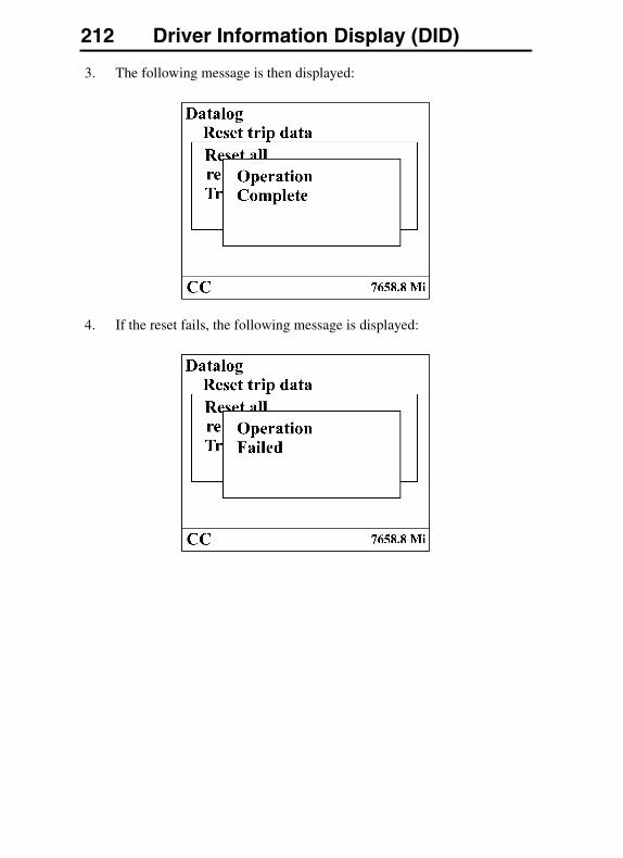
212 Driver Information Display (DID)
3. The following message is then displayed:
4. If the reset fails, the following message is displayed:

Driver Information Display (DID) 213
Password
Certain functions are password-protected and there are a number of passwords for the display (it is also possible to disable the password protection for functions, which is useful when the owner is the driver. Contact your local Volvo dealer to set this function).
1. Password
These passwords give the user access to all password-protected functions.
This password must be changed to prevent unauthorized access to the menus.
See “5. Change Password” on page 196 to change the password.
Switch between the alternatives using “Δ/∇” arrows. Confirm selection by pressing “↵ ”. Press “Esc” to return to the main menu.
The following menus are password-protected and marked with a key symbol in the menus:
� Fleet Limits
� Fleet ID
� Reset (applies to a number of functions)
When the ignition key has been in the stop position for more than 60 seconds or the batteries have been disconnected, the password must be entered again in order to access all the functions.
No functions should be password-protected:
To make all menus available without password you must go to: “Password” and press “↵ ”.
You can also go to a password-protected menu and press “↵ ”. A password entry box is displayed.
1. Select the “Password” menu.
2. The password consists of a four-digit number, 0000–9999, that is scrolled forward using “Δ/∇” arrows on the control lever (one number at a time) followed by pressing “↵ ”. The display shows the following:
Press “↵ ” when the correct password has been entered.
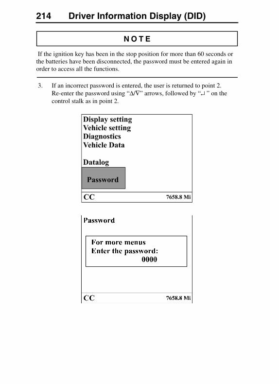
214 Driver Information Display (DID)
If the ignition key has been in the stop position for more than 60 seconds or the batteries have been disconnected, the password must be entered again in order to access all the functions.
3. If an incorrect password is entered, the user is returned to point 2. Re-enter the password using “Δ/∇” arrows, followed by “↵ ” on the control stalk as in point 2.
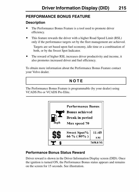
Driver Information Display (DID) 215
PERFORMANCE BONUS FEATURE
Description
� The Performance Bonus Feature is a tool used to promote driver efficiency.
� This feature rewards the driver with a higher Road Speed Limit (RSL) only if the performance targets set by the fleet management are achieved.
Targets are set based upon fuel economy, idle time or a combination of both, or by the Sweet Spot Indicator.
� The reward of higher RSL increases driver productivity and income, it also promotes increased driver and fuel efficiency.
To obtain more information about the Performance Bonus Feature contact your Volvo dealer.
The Performance Bonus Feature is programmable (by your dealer) using VCADS Pro or VCADS Pro Elite.
Performance Bonus Status Reward
Driver reward is shown in the Driver Information Display screen (DID). Once the ignition is turned ON, the Performance Bonus status appears and remains on the screen for 15 seconds. See illustration.

216 Driver Information Display (DID)
Only priority 1 messages will temporarily close the rewards status menu.
Rolling Buffer
The “rolling buffer” is set to measure distance driven. The buffer may be set at a short or long distance. A short buffer results in a faster reward, (or loss of reward) which provides driving fuel economy training to the driver, permitting the driver easy memory of the input to the buffer during this short period of time.
A long buffer setting allows for the daily activities to “smooth out”. In this case the reward is based on weekly/monthly activity.
The DID will inform the Performance Bonus status by showing the actual status and target within the parenthesis.
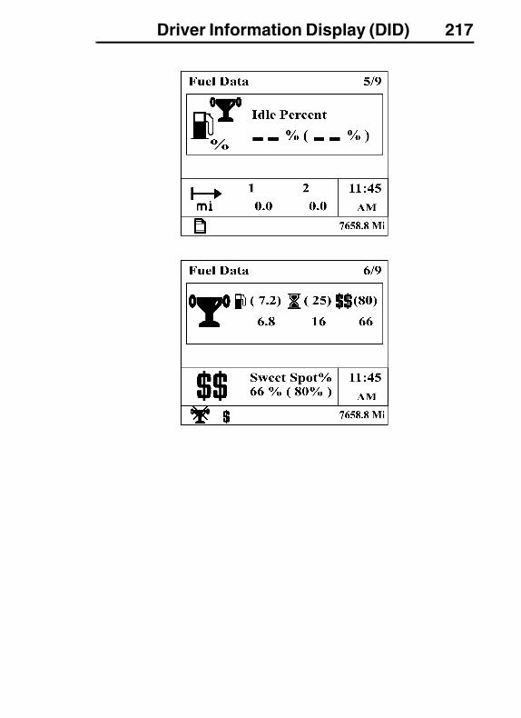
Driver Information Display (DID) 217
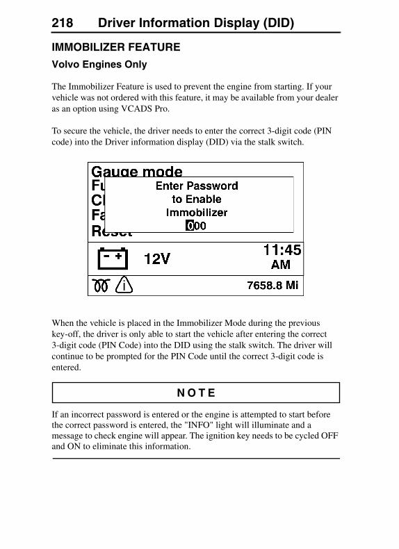
218 Driver Information Display (DID)
IMMOBILIZER FEATURE
Volvo Engines Only
The Immobilizer Feature is used to prevent the engine from starting. If your vehicle was not ordered with this feature, it may be available from your dealer as an option using VCADS Pro.
To secure the vehicle, the driver needs to enter the correct 3-digit code (PIN code) into the Driver information display (DID) via the stalk switch.
When the vehicle is placed in the Immobilizer Mode during the previous key-off, the driver is only able to start the vehicle after entering the correct 3-digit code (PIN Code) into the DID using the stalk switch. The driver will continue to be prompted for the PIN Code until the correct 3-digit code is entered.
If an incorrect password is entered or the engine is attempted to start before the correct password is entered, the "INFO" light will illuminate and a message to check engine will appear. The ignition key needs to be cycled OFF and ON to eliminate this information.
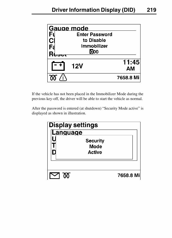
Driver Information Display (DID) 219
If the vehicle has not been placed in the Immobilizer Mode during the previous key-off, the driver will be able to start the vehicle as normal.
After the password is entered (at shutdown) “Security Mode active” is displayed as shown in illustration.
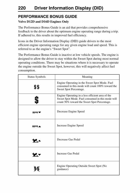
220 Driver Information Display (DID)
PERFORMANCE BONUS GUIDEVolvo D12D and D16D Engines Only
The Performance Bonus Guide is an aid that provides comprehensive feedback to the driver about the optimum engine operating range during a trip. If adhered to, this results in improved fuel efficiency.
Icons in the Driver Information Display (DID) guide drivers to the most efficient engine operating range for any given engine load and speed. This is referred to as the engine's “Sweet Spot”.
The Performance Bonus Guide is inactive at low vehicle speeds. The engine is designed to allow the driver to stay within the Sweet Spot during most normal operating conditions. There may be situations where it is necessary to operate the engine outside the Sweet Spot, however, this will negatively affect fuel consumption.
Status Symbols Meaning
Engine Operating in the Sweet Spot Mode. Fuel consumed in this mode will count 100% toward the Sweet Spot Percentage.
Engine Operating in a less efficient area of the Sweet Spot Mode. Fuel consumed in this mode will count 50% toward the Sweet Spot Percentage.
Decrease Engine Speed
Increase Engine Speed
Decrease Gas Pedal
Increase Gas Pedal
Engine Operating Outside Sweet Spot (No guidance)
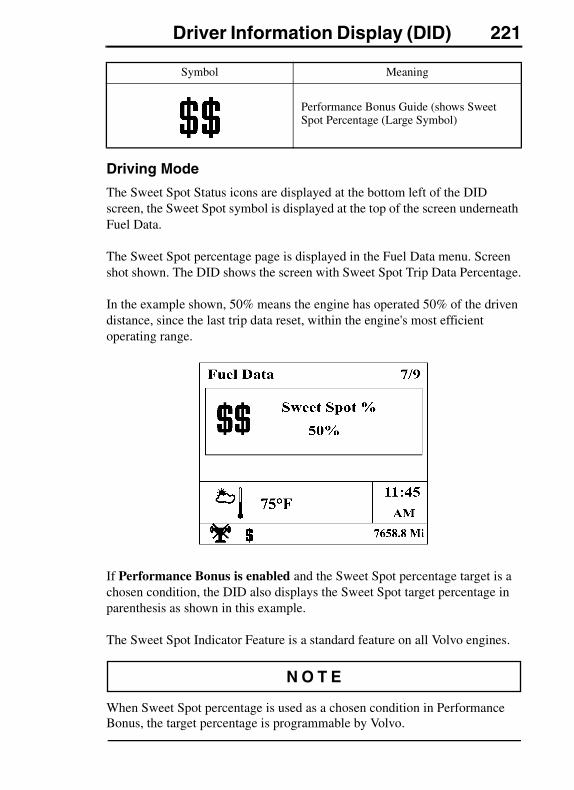
Driver Information Display (DID) 221
Driving Mode
The Sweet Spot Status icons are displayed at the bottom left of the DID screen, the Sweet Spot symbol is displayed at the top of the screen underneath Fuel Data.
The Sweet Spot percentage page is displayed in the Fuel Data menu. Screen shot shown. The DID shows the screen with Sweet Spot Trip Data Percentage.
In the example shown, 50% means the engine has operated 50% of the driven distance, since the last trip data reset, within the engine's most efficient operating range.
If Performance Bonus is enabled and the Sweet Spot percentage target is a chosen condition, the DID also displays the Sweet Spot target percentage in parenthesis as shown in this example.
The Sweet Spot Indicator Feature is a standard feature on all Volvo engines.
When Sweet Spot percentage is used as a chosen condition in Performance Bonus, the target percentage is programmable by Volvo.
Symbol Meaning
Performance Bonus Guide (shows Sweet Spot Percentage (Large Symbol)
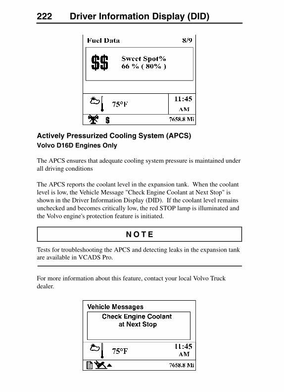
222 Driver Information Display (DID)
Actively Pressurized Cooling System (APCS)Volvo D16D Engines Only
The APCS ensures that adequate cooling system pressure is maintained under all driving conditions
The APCS reports the coolant level in the expansion tank. When the coolant level is low, the Vehicle Message "Check Engine Coolant at Next Stop" is shown in the Driver Information Display (DID). If the coolant level remains unchecked and becomes critically low, the red STOP lamp is illuminated and the Volvo engine's protection feature is initiated.
Tests for troubleshooting the APCS and detecting leaks in the expansion tank are available in VCADS Pro.
For more information about this feature, contact your local Volvo Truck dealer.
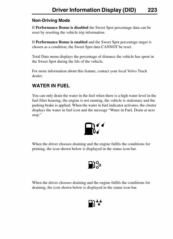
Driver Information Display (DID) 223
Non-Driving Mode
If Performance Bonus is disabled the Sweet Spot percentage data can be reset by resetting the vehicle trip information.
If Performance Bonus is enabled and the Sweet Spot percentage target is chosen as a condition, the Sweet Spot data CANNOT be reset.
Total Data menu displays the percentage of distance the vehicle has spent in the Sweet Spot during the life of the vehicle.
For more information about this feature, contact your local Volvo Truck dealer.
WATER IN FUEL
You can only drain the water in the fuel when there is a high water level in the fuel filter housing, the engine is not running, the vehicle is stationary and the parking brake is applied. When the water in fuel indicator activates, the cluster displays the water in fuel icon and the message “Water in Fuel, Drain at next stop.”
When the driver chooses draining and the engine fulfils the conditions for priming, the icon shown below is displayed in the status icon bar.
When the driver chooses draining and the engine fulfils the conditions for draining, the icon shown below is displayed in the status icon bar.
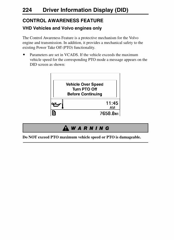
224 Driver Information Display (DID)
CONTROL AWARENESS FEATURE
VHD Vehicles and Volvo engines only
The Control Awareness Feature is a protective mechanism for the Volvo engine and transmission. In addition, it provides a mechanical safety to the existing Power Take Off (PTO) functionality.
� Parameters are set in VCADS. If the vehicle exceeds the maximum vehicle speed for the corresponding PTO mode a message appears on the DID screen as shown:
Do NOT exceed PTO maximum vehicle speed or PTO is damageable.

Heating and Air Conditioning 225HEATING AND AIR CONDITIONING
GENERALThere are two different air conditioning systems. Depending on your vehicle, you will have one of these two air conditioning units installed:
1. Electronic Climate Control (ECC)
2. Manual Climate Control (MCC)
For both climate control systems (ECC and MCC), after a pre-determined number of “vehicle starts” the climate unit will recalibrate the door positions, which may take several seconds before the airflow returns to the selected distribution mode.
AIR CONDITIONING ELECTRONIC CLIMATE CONTROL (ECC)
ECC Controls
1. AC OFF button: turns the air conditioning OFF. The arrow in the illustration shows the LED light which is AMBER or RED indicating the AC compressor is OFF. The ECC will still try to maintain the selected temperature in the cab without the compressor.
2. Temperature knob3. Fan speed knob4. Recirculation button5. Air distribution knob
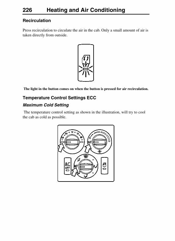
226 Heating and Air Conditioning
Recirculation
Press recirculation to circulate the air in the cab. Only a small amount of air is taken directly from outside.
The light in the button comes on when the button is pressed for air recirculation.
Temperature Control Settings ECC
Maximum Cold Setting
The temperature control setting as shown in the illustration, will try to cool the cab as cold as possible.
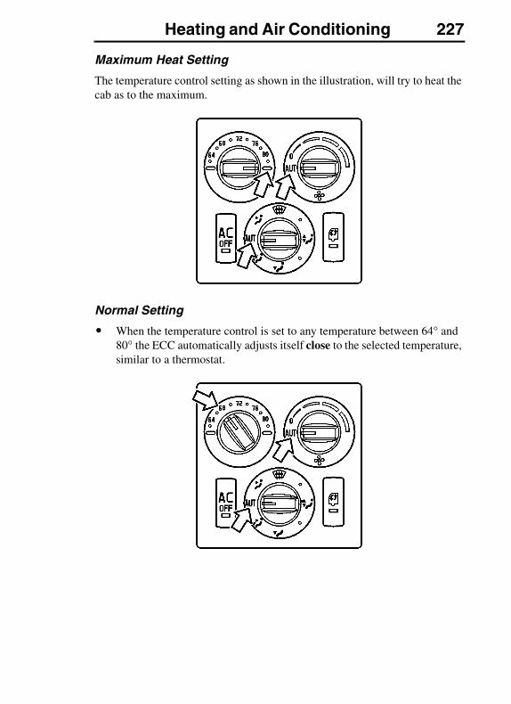
Heating and Air Conditioning 227
Maximum Heat Setting
The temperature control setting as shown in the illustration, will try to heat the cab as to the maximum.
Normal Setting
� When the temperature control is set to any temperature between 64° and 80° the ECC automatically adjusts itself close to the selected temperature, similar to a thermostat.
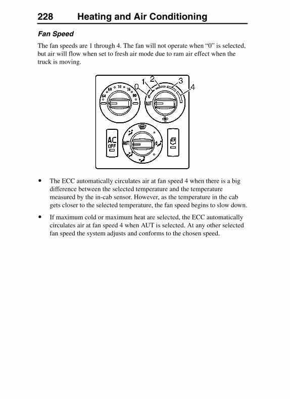
228 Heating and Air Conditioning
Fan Speed
The fan speeds are 1 through 4. The fan will not operate when “0” is selected, but air will flow when set to fresh air mode due to ram air effect when the truck is moving.
� The ECC automatically circulates air at fan speed 4 when there is a big difference between the selected temperature and the temperature measured by the in-cab sensor. However, as the temperature in the cab gets closer to the selected temperature, the fan speed begins to slow down.
� If maximum cold or maximum heat are selected, the ECC automatically circulates air at fan speed 4 when AUT is selected. At any other selected fan speed the system adjusts and conforms to the chosen speed.
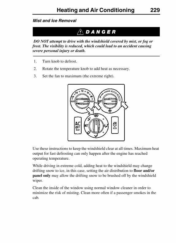
Heating and Air Conditioning 229
Mist and Ice Removal
DO NOT attempt to drive with the windshield covered by mist, or fog or frost. The visibility is reduced, which could lead to an accident causing severe personal injury or death.
1. Turn knob to defrost.
2. Rotate the temperature knob to add heat as necessary.
3. Set the fan to maximum (the extreme right).
Use these instructions to keep the windshield clear at all times. Maximum heat output for fast defrosting can only happen after the engine has reached operating temperature.
While driving in extreme cold, adding heat to the windshield may change drifting snow to ice, in this case, setting the air distribution to floor and/or panel only may allow the drifting snow to be brushed off by the windshield wiper.
Clean the inside of the window using normal window cleaner in order to minimize the risk of misting. Clean more often if a passenger smokes in the cab.

230 Heating and Air Conditioning
ECC Air Distribution
The temperature sensor shown in the illustration, detects the temperature in the cab. DO NOT cover the sensor, and DO NOT place warm objects, like coffee makers or refrigerators, close to the sensor.
Always allow the dashboard vents (see arrows in illustration) to remain open. Irrespective of how the air distribution is set, a small amount of air will always come from the dashboard vents to ensure the temperature in the cab is correct.
Floor Mode: Unheated air is leaked to the panel vent to balance the heat rising from the floor.
1. Temperature Sensor
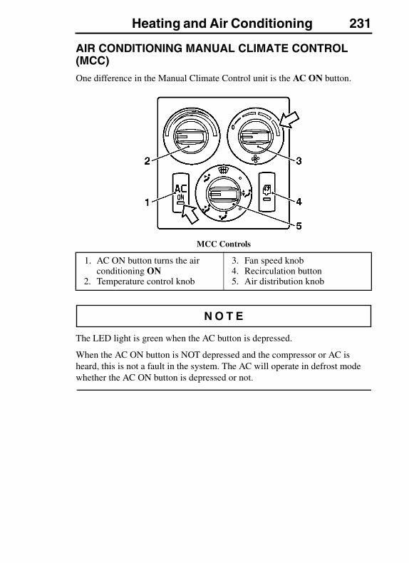
Heating and Air Conditioning 231
AIR CONDITIONING MANUAL CLIMATE CONTROL (MCC)One difference in the Manual Climate Control unit is the AC ON button.
MCC Controls
The LED light is green when the AC button is depressed.
When the AC ON button is NOT depressed and the compressor or AC is heard, this is not a fault in the system. The AC will operate in defrost mode whether the AC ON button is depressed or not.
1. AC ON button turns the air conditioning ON
2. Temperature control knob
3. Fan speed knob4. Recirculation button5. Air distribution knob
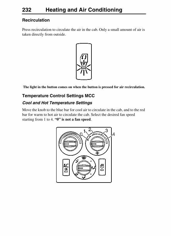
232 Heating and Air Conditioning
Recirculation
Press recirculation to circulate the air in the cab. Only a small amount of air is taken directly from outside.
The light in the button comes on when the button is pressed for air recirculation.
Temperature Control Settings MCC
Cool and Hot Temperature Settings
Move the knob to the blue bar for cool air to circulate in the cab, and to the red bar for warm to hot air to circulate the cab. Select the desired fan speed starting from 1 to 4. “0” is not a fan speed.
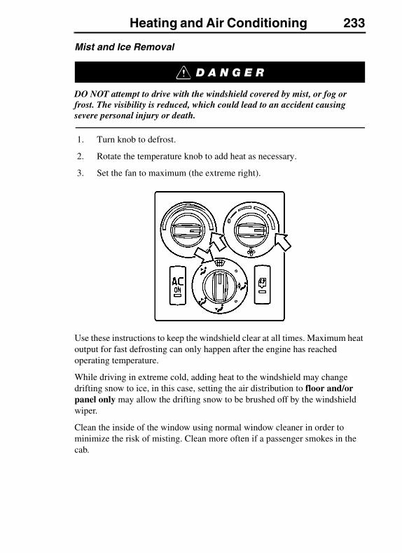
Heating and Air Conditioning 233
Mist and Ice Removal
DO NOT attempt to drive with the windshield covered by mist, or fog or frost. The visibility is reduced, which could lead to an accident causing severe personal injury or death.
1. Turn knob to defrost.
2. Rotate the temperature knob to add heat as necessary.
3. Set the fan to maximum (the extreme right).
Use these instructions to keep the windshield clear at all times. Maximum heat output for fast defrosting can only happen after the engine has reached operating temperature.
While driving in extreme cold, adding heat to the windshield may change drifting snow to ice, in this case, setting the air distribution to floor and/or panel only may allow the drifting snow to be brushed off by the windshield wiper.
Clean the inside of the window using normal window cleaner in order to minimize the risk of misting. Clean more often if a passenger smokes in the cab.

234 Heating and Air Conditioning
MCC Air Distribution
Always allow the dashboard vents (see arrows in illustration) to remain open. Irrespective of how the air distribution is set, a small amount of air will always come from the dashboard vents to ensure the temperature in the cab is correct.
Floor Mode: Unheated air is leaked to the panel vent to balance the heat rising from the floor.
CAB VENTILATION
Ventilation Guidelines
If at any time there is any question whether exhaust fumes are entering the cab, determine the cause of the fumes and have it corrected as soon as possible. If the vehicle must be driven under these conditions, drive only with all windows open.
Protect against carbon monoxide entry into the cab. Keep the engine exhaust system, cab and cab ventilation system properly maintained. It is recommended that the exhaust system and cab are inspected by a competent technician:
� At every engine oil change.
� Whenever a change is noticed in the sound of the exhaust system.
� Whenever the exhaust system, underbody or cab is damaged.
Heating and Air Conditioning 235
DO NOT breathe the engine exhaust gas. It contains carbon monoxide, which has no color or odor. Carbon monoxide is a dangerous gas which can cause unconsciousness or death.
Diesel engine exhaust and some of its content are known to the state of California to cause cancer, birth defects or other reproductive harm.
To allow proper operation of the vehicle ventilation system, keep the inlet grille at the base of the windshield clear of snow, ice, leaves and other obstructions at all times.
DO NOT park the vehicle and let the engine run or idle for more than 10 minutes with the ventilation system control switch in the OFF position. Even with the ventilation system ON, running the engine while parked or stopped for long periods of time is not recommended. Entry of carbon monoxide into the cab is possible with a poorly repaired, damaged or corroded exhaust system or cab.
DO NOT run the engine in confined areas, such as garages or next to a building, any more than necessary. The area must be properly ventilated. When the vehicle must be stopped with the engine running for more than a few minutes:
� Adjust the heating or cooling system to force outside air into the cab. Do this by setting the fan to medium or high speed and with the controls set in any position except for recirculation of air inside of the cab.
� Keep the exhaust pipe area clear to help reduce the buildup of exhaust gas under the vehicle.
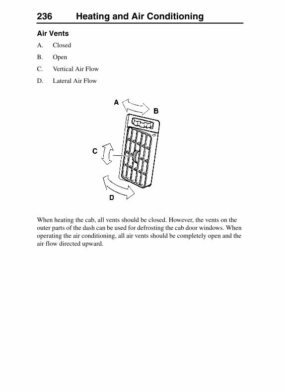
236 Heating and Air Conditioning
Air Vents
A. Closed
B. Open
C. Vertical Air Flow
D. Lateral Air Flow
When heating the cab, all vents should be closed. However, the vents on the outer parts of the dash can be used for defrosting the cab door windows. When operating the air conditioning, all air vents should be completely open and the air flow directed upward.
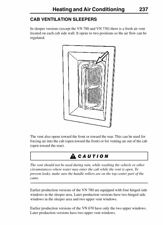
Heating and Air Conditioning 237
CAB VENTILATION SLEEPERS
In sleeper versions (except the VN 780 and VN 730) there is a fresh air vent located on each cab side wall. It opens to two positions so the air flow can be regulated.
The vent also opens toward the front or toward the rear. This can be used for forcing air into the cab (open toward the front) or for venting air out of the cab (open toward the rear).
The vent should not be used during rain, while washing the vehicle or other circumstances where water may enter the cab while the vent is open. To prevent leaks, make sure the handle rollers are on the top center part of the cams.
Earlier production versions of the VN 780 are equipped with four hinged side windows in the sleeper area. Later production versions have two hinged side windows in the sleeper area and two upper vent windows.
Earlier production versions of the VN 670 have only the two upper windows. Later production versions have two upper vent windows.
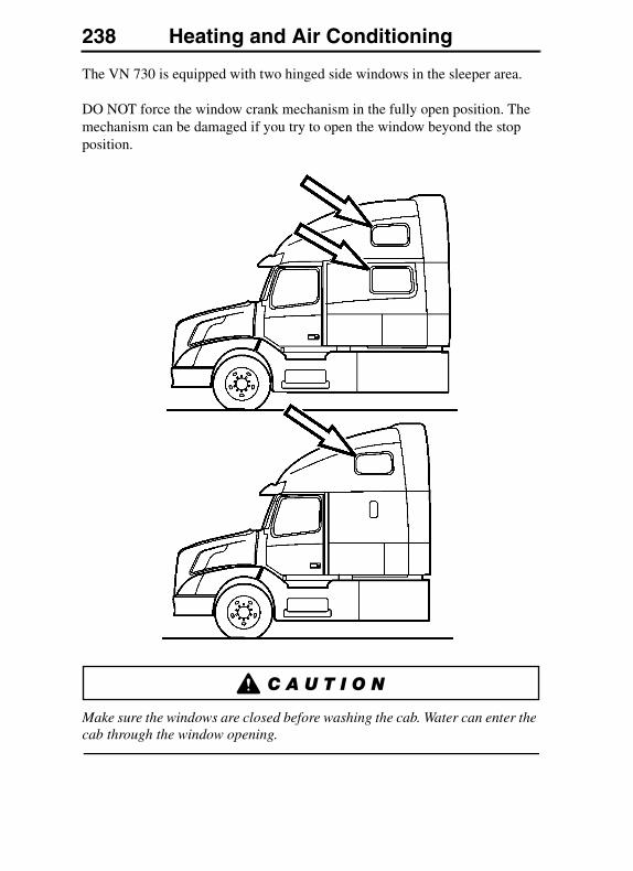
238 Heating and Air Conditioning
The VN 730 is equipped with two hinged side windows in the sleeper area.
DO NOT force the window crank mechanism in the fully open position. The mechanism can be damaged if you try to open the window beyond the stop position.
Make sure the windows are closed before washing the cab. Water can enter the cab through the window opening.

Heating and Air Conditioning 239
Do not open the cab sleeper windows when the vehicle is in motion. Opening the windows while the vehicle is in motion will damage the sleeper windows.
SLEEPER CLIMATE UNIT VNThe sleeper cabs have an A/C and heater unit that is located in the passenger side luggage compartment. The sleeper unit operates from the same heater and air conditioning supply as the main unit. The heater can be operated independently from the main unit as long as the engine is running.
For the air conditioning to operate, the engine must be running, the air conditioning button must be pressed in and the fan control must be set at least for speed 1 on the main control panel.
Air is taken from the sleeper area through a filter in the lower bunk support wall and heated or cooled in the “underbunk” unit. Outlet air can be directed with the vents in the side walls.
For the best results when using the air conditioning, direct the air flow upward in the sleeper area.
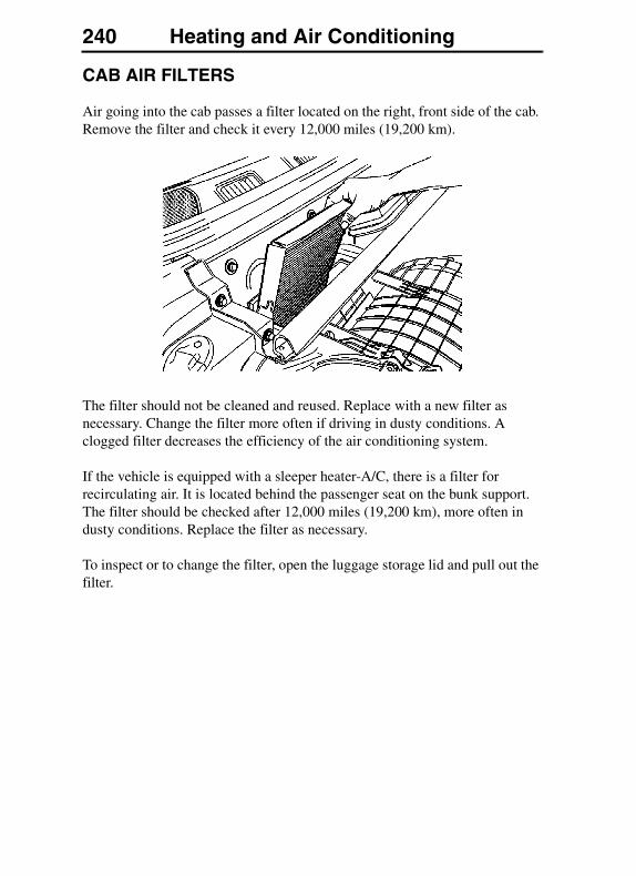
240 Heating and Air Conditioning
CAB AIR FILTERS
Air going into the cab passes a filter located on the right, front side of the cab. Remove the filter and check it every 12,000 miles (19,200 km).
The filter should not be cleaned and reused. Replace with a new filter as necessary. Change the filter more often if driving in dusty conditions. A clogged filter decreases the efficiency of the air conditioning system.
If the vehicle is equipped with a sleeper heater-A/C, there is a filter for recirculating air. It is located behind the passenger seat on the bunk support. The filter should be checked after 12,000 miles (19,200 km), more often in dusty conditions. Replace the filter as necessary.
To inspect or to change the filter, open the luggage storage lid and pull out the filter.
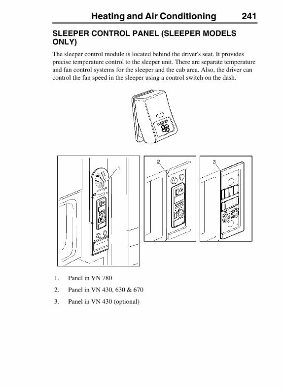
Heating and Air Conditioning 241
SLEEPER CONTROL PANEL (SLEEPER MODELS ONLY)The sleeper control module is located behind the driver's seat. It provides precise temperature control to the sleeper unit. There are separate temperature and fan control systems for the sleeper and the cab area. Also, the driver can control the fan speed in the sleeper using a control switch on the dash.
1. Panel in VN 780
2. Panel in VN 430, 630 & 670
3. Panel in VN 430 (optional)
242 Heating and Air Conditioning
This dual control usage provides optimum comfort to the driver and passenger (if any) in both compartments. The sleeper control module is used to operate the following:
� Auxiliary Heating, Venting and Air Conditioning
� Alarm Clock/Timer
� Interior Sleeper Lights
� Circuit Protection (fuses)
� Battery Voltage Protection (see “Battery Voltage Protection System” on page 356)
� Parking Heater (Optional)
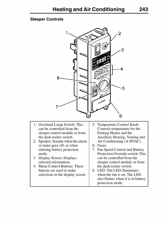
Heating and Air Conditioning 243
Sleeper Controls
1. Overhead Lamp Switch: This can be controlled from the sleeper control module or from the dash rocker switch.
2. Speaker: Sounds when the alarm or timer goes off, or when entering battery protection mode.
3. Display Screen: Displays selected information.
4. Menu Control Buttons: These buttons are used to make selections in the display screen.
5. Temperature Control Knob: Controls temperature for the Parking Heater and the Auxiliary Heating, Venting and Air Conditioning (A-HVAC).
6. Fuses.7. Fan Speed Control and Battery
Protection Override switch: This can be controlled from the sleeper control module or from the dash rocker switch.
8. LED: The LED illuminates when the fan is on. The LED also flashes when it is in battery protection mode.

244 Heating and Air Conditioning
Display Screen
The display screen contains LED icons for HEAT, SET, IDLE, TIMER, °F, °C, AM, PM, & ALARM. Press the Menu/Snooze bar to rotate through TIME DISPLAY, ALARM, HEAT & TIMER menus.
After 5 minutes of inactivity the display will shut off.
Underneath the display screen there are five push buttons:
SET — Establishes values and confirms any selection made
ON/OFF — Turns ALARM, TIMER or DISPLAY ON/OFF
+ — Adds increments
– — Reduces increments
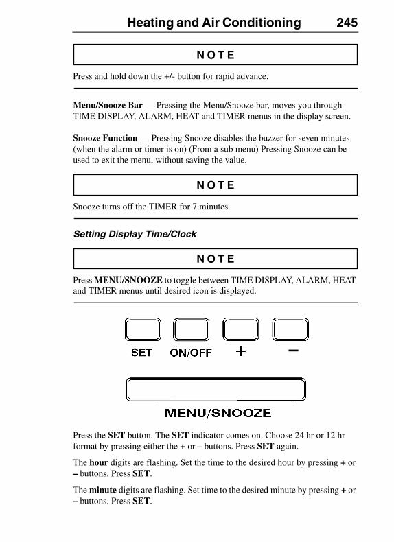
Heating and Air Conditioning 245
Press and hold down the +/- button for rapid advance.
Menu/Snooze Bar — Pressing the Menu/Snooze bar, moves you through TIME DISPLAY, ALARM, HEAT and TIMER menus in the display screen.
Snooze Function — Pressing Snooze disables the buzzer for seven minutes (when the alarm or timer is on) (From a sub menu) Pressing Snooze can be used to exit the menu, without saving the value.
Snooze turns off the TIMER for 7 minutes.
Setting Display Time/Clock
Press MENU/SNOOZE to toggle between TIME DISPLAY, ALARM, HEAT and TIMER menus until desired icon is displayed.
Press the SET button. The SET indicator comes on. Choose 24 hr or 12 hr format by pressing either the + or – buttons. Press SET again.
The hour digits are flashing. Set the time to the desired hour by pressing + or – buttons. Press SET.
The minute digits are flashing. Set time to the desired minute by pressing + or – buttons. Press SET.
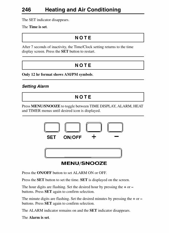
246 Heating and Air Conditioning
The SET indicator disappears.
The Time is set.
After 7 seconds of inactivity, the Time/Clock setting returns to the time display screen. Press the SET button to restart.
Only 12 hr format shows AM/PM symbols.
Setting Alarm
Press MENU/SNOOZE to toggle between TIME DISPLAY, ALARM, HEAT and TIMER menus until desired icon is displayed.
Press the ON/OFF button to set ALARM ON or OFF.
Press the SET button to set the time. SET is displayed on the screen.
The hour digits are flashing. Set the desired hour by pressing the + or – buttons. Press SET again to confirm selection.
The minute digits are flashing. Set the desired minutes by pressing the + or – buttons. Press SET again to confirm selection.
The ALARM indicator remains on and the SET indicator disappears.
The Alarm is set.

Heating and Air Conditioning 247
After 7 seconds of inactivity, the Time/Clock setting returns to the time display screen. Press the SET button to restart.
Setting Parking Heater
Press MENU/SNOOZE to toggle between TIME DISPLAY, ALARM, HEAT and TIMER menus until desired icon is displayed.
Press ON/OFF button to immediately turn on the Manual HEAT.
Press SET to select three different modes and time. SET is displayed at the top left of the display screen.
Press the + or – buttons to toggle between HEAT/AUTO/CYCL.
HEAT: Manually turn ON and OFF.
AUTO: Set a time in the future to automatically turn on.
CYCL: Set one time to continuously cycle between ON and OFF.
When the selection is complete, for example, select AUTO and press SET. Current ON or OFF status is displayed. Make desired selection by pressing ON/OFF button. Press SET.
Hour digits flashing. Press the + or – buttons to select the desired hour. Press SET, the hour is set.
Minute digits flashing. Press the + or – buttons to select the desired minutes. Press SET, the minute is set.
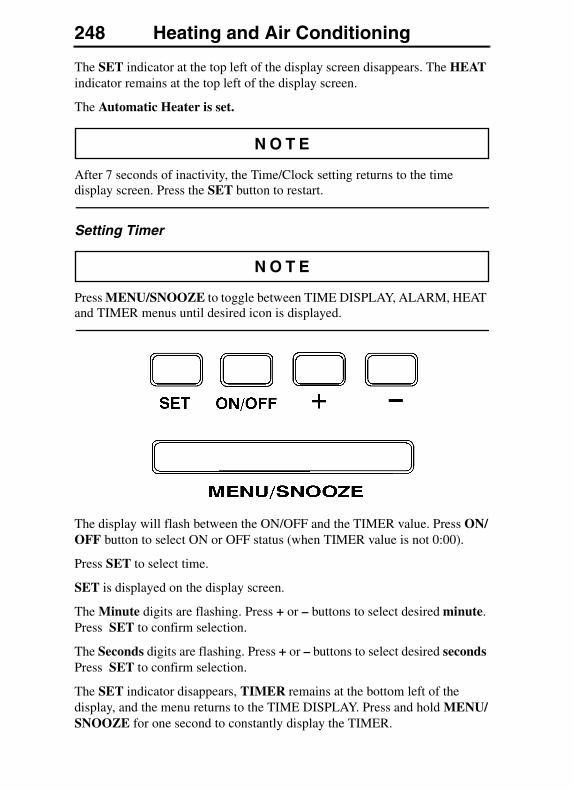
248 Heating and Air Conditioning
The SET indicator at the top left of the display screen disappears. The HEAT indicator remains at the top left of the display screen.
The Automatic Heater is set.
After 7 seconds of inactivity, the Time/Clock setting returns to the time display screen. Press the SET button to restart.
Setting Timer
Press MENU/SNOOZE to toggle between TIME DISPLAY, ALARM, HEAT and TIMER menus until desired icon is displayed.
The display will flash between the ON/OFF and the TIMER value. Press ON/OFF button to select ON or OFF status (when TIMER value is not 0:00).
Press SET to select time.
SET is displayed on the display screen.
The Minute digits are flashing. Press + or – buttons to select desired minute. Press SET to confirm selection.
The Seconds digits are flashing. Press + or – buttons to select desired seconds Press SET to confirm selection.
The SET indicator disappears, TIMER remains at the bottom left of the display, and the menu returns to the TIME DISPLAY. Press and hold MENU/SNOOZE for one second to constantly display the TIMER.
Heating and Air Conditioning 249
Note: the Alarm will sound when the TIMER count reaches 0:00. Press ON/OFF button to turn OFF alarm for TIMER.
Snooze turns off the TIMER for 7 minutes.
After 7 seconds of inactivity, the Time/Clock setting returns to the time display screen. Press the SET button to restart.
250 Heating and Air Conditioning
PARKING HEATER (OPTIONAL, SLEEPER MODELS ONLY)
DO NOT fuel the vehicle or handle flammable liquids in the vicinity of an operating parking heater. The fuel vapors can be ignited, causing an explosion or fire resulting in severe personal injury or death.
DO NOT store flammable items close to the parking heater or put items on top of it. Flammable items should not be closer than 2 inches (50 mm). The item may ignite and cause a fire resulting in severe personal injury or death.
DO NOT run heater while vehicle is in an enclosed area. The exhaust gasses contain carbon monoxide (CO). If not vented to the atmosphere, there could be a buildup of dangerous levels of CO which may lead to unconsciousness and later death.
The parking heater is a very hot object. DO NOT touch the heater when it is in operation or shortly thereafter. Touching a heater may cause burns to exposed skin.
The heater air inlet is located in the bunk wall in front of the heater. DO NOT attempt to put small items or store flat items between the bunk and the cabinet/refrigerator. The air intake can be blocked which causes the heater to overheat and shut down.

Heating and Air Conditioning 251
The parking heater is a diesel fuel burner that heats the air in the cab. Air is taken from the cab and returned heated. Combustion air and exhaust is taken from, and released to the outside air.
To safeguard from the heater operating after a turnover accident, there is a fuel shut-off valve in the fuel delivery system.
Fuel Parking Heater
A fuel heated parking heater is available as an option. It is located in the left hand luggage compartment. The heater provides automatically regulated heat that is distributed through its own vents into the sleeper section of the cab.
252 SeatsSEATS
GENERALSeveral seats can be used in the vehicles. If the seat installed in the vehicle is not explained in this section, see your authorized Volvo dealer.
Before adjusting or fastening the seat belt, move the seat forward or rearward and adjust the seat height as necessary. Sit erect and adjust the seat cushion and seat back to obtain a comfortable driving position.
All adjustments are to be made while the operator is seated and the vehicle is stationary. DO NOT adjust the seat position while driving the vehicle. Failure to follow this warning can result in loss of vehicle control, which can result in serious personal injury or death in the event of a vehicle accident.
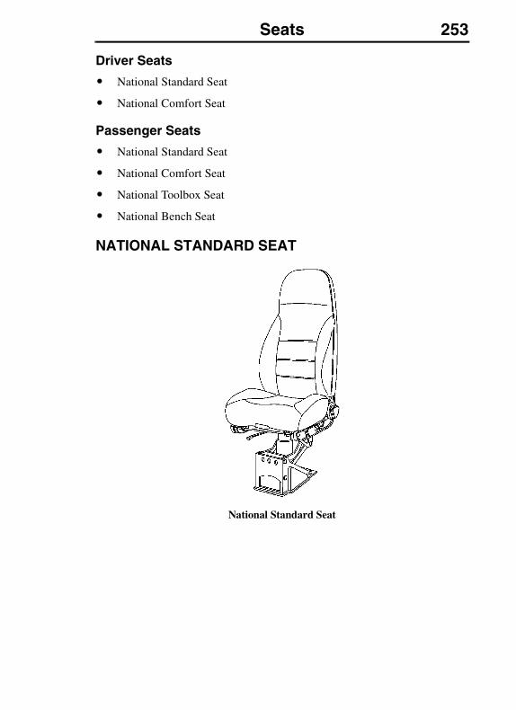
Seats 253
Driver Seats
� National Standard Seat
� National Comfort Seat
Passenger Seats
� National Standard Seat
� National Comfort Seat
� National Toolbox Seat
� National Bench Seat
NATIONAL STANDARD SEAT
National Standard Seat
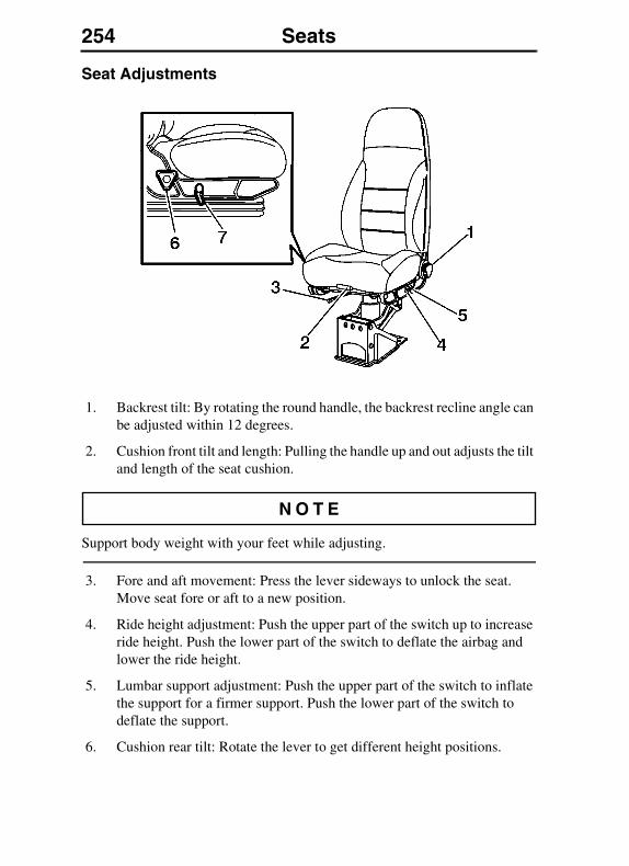
254 Seats
Seat Adjustments
1. Backrest tilt: By rotating the round handle, the backrest recline angle can be adjusted within 12 degrees.
2. Cushion front tilt and length: Pulling the handle up and out adjusts the tilt and length of the seat cushion.
Support body weight with your feet while adjusting.
3. Fore and aft movement: Press the lever sideways to unlock the seat. Move seat fore or aft to a new position.
4. Ride height adjustment: Push the upper part of the switch up to increase ride height. Push the lower part of the switch to deflate the airbag and lower the ride height.
5. Lumbar support adjustment: Push the upper part of the switch to inflate the support for a firmer support. Push the lower part of the switch to deflate the support.
6. Cushion rear tilt: Rotate the lever to get different height positions.
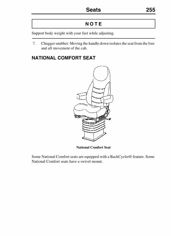
Seats 255
Support body weight with your feet while adjusting.
7. Chugger snubber: Moving the handle down isolates the seat from the fore and aft movement of the cab.
NATIONAL COMFORT SEAT
National Comfort Seat
Some National Comfort seats are equipped with a BackCycler® feature. Some National Comfort seats have a swivel mount.
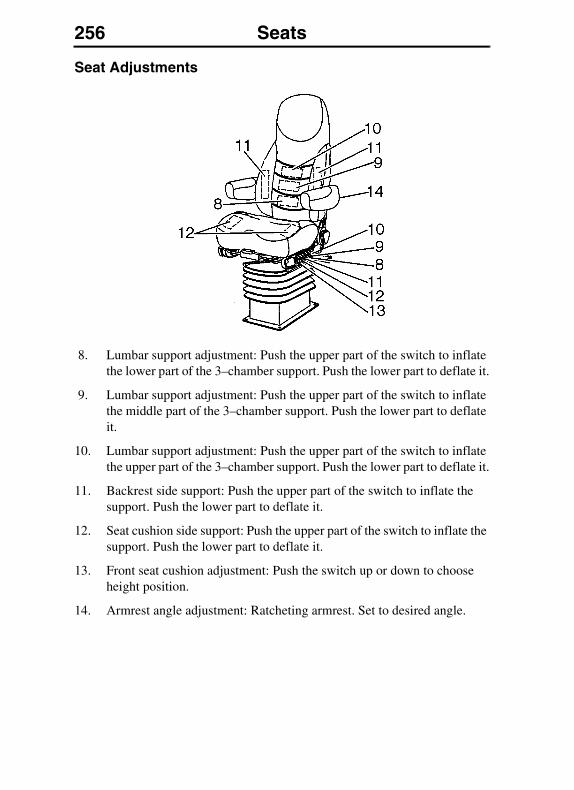
256 Seats
Seat Adjustments
8. Lumbar support adjustment: Push the upper part of the switch to inflate the lower part of the 3–chamber support. Push the lower part to deflate it.
9. Lumbar support adjustment: Push the upper part of the switch to inflate the middle part of the 3–chamber support. Push the lower part to deflate it.
10. Lumbar support adjustment: Push the upper part of the switch to inflate the upper part of the 3–chamber support. Push the lower part to deflate it.
11. Backrest side support: Push the upper part of the switch to inflate the support. Push the lower part to deflate it.
12. Seat cushion side support: Push the upper part of the switch to inflate the support. Push the lower part to deflate it.
13. Front seat cushion adjustment: Push the switch up or down to choose height position.
14. Armrest angle adjustment: Ratcheting armrest. Set to desired angle.
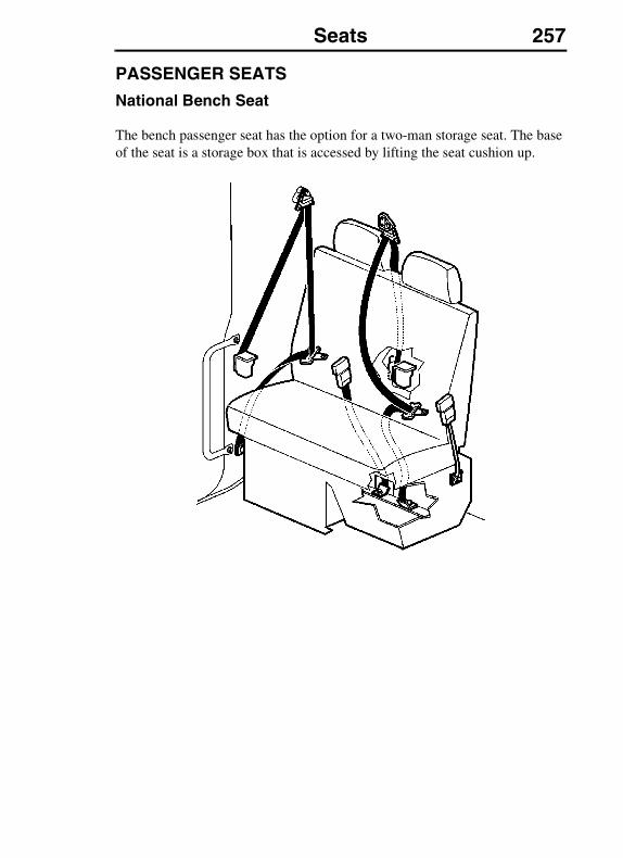
Seats 257
PASSENGER SEATS
National Bench Seat
The bench passenger seat has the option for a two-man storage seat. The base of the seat is a storage box that is accessed by lifting the seat cushion up.
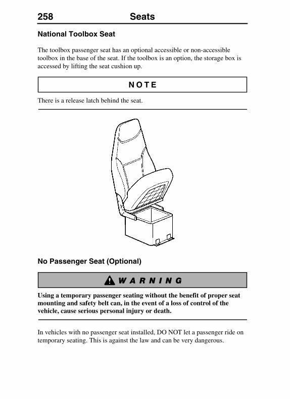
258 Seats
National Toolbox Seat
The toolbox passenger seat has an optional accessible or non-accessible toolbox in the base of the seat. If the toolbox is an option, the storage box is accessed by lifting the seat cushion up.
There is a release latch behind the seat.
No Passenger Seat (Optional)
Using a temporary passenger seating without the benefit of proper seat mounting and safety belt can, in the event of a loss of control of the vehicle, cause serious personal injury or death.
In vehicles with no passenger seat installed, DO NOT let a passenger ride on temporary seating. This is against the law and can be very dangerous.

Cab Interior and Sleeper 259CAB INTERIOR AND SLEEPER
SLEEPER BUNKS
General
Upper and lower bunks are available in the VN 780, 730, 670 and 630 models. The lower bunk is standard while the upper bunk is optional. The VN 430 is equipped with one lower bunk.
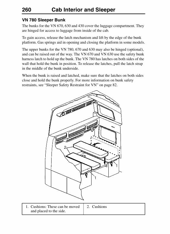
260 Cab Interior and Sleeper
VN 780 Sleeper BunkThe bunks for the VN 670, 630 and 430 cover the luggage compartment. They are hinged for access to luggage from inside of the cab.
To gain access, release the latch mechanism and lift by the edge of the bunk platform. Gas springs aid in opening and closing the platform in some models.
The upper bunks for the VN 780, 670 and 630 may also be hinged (optional), and can be raised out of the way. The VN 670 and VN 630 use the safety bunk harness latch to hold up the bunk. The VN 780 has latches on both sides of the wall that hold the bunk in position. To release the latches, pull the latch strap in the middle of the bunk underside.
When the bunk is raised and latched, make sure that the latches on both sides close and hold the bunk properly. For more information on bunk safety restraints, see “Sleeper Safety Restraint for VN” on page 82.
1. Cushions: These can be moved and placed to the side.
2. Cushions
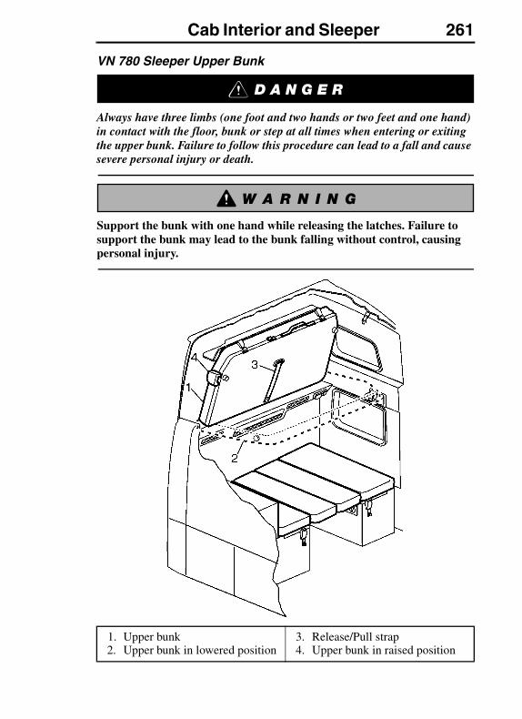
Cab Interior and Sleeper 261
VN 780 Sleeper Upper Bunk
Always have three limbs (one foot and two hands or two feet and one hand) in contact with the floor, bunk or step at all times when entering or exiting the upper bunk. Failure to follow this procedure can lead to a fall and cause severe personal injury or death.
Support the bunk with one hand while releasing the latches. Failure to support the bunk may lead to the bunk falling without control, causing personal injury.
1. Upper bunk2. Upper bunk in lowered position
3. Release/Pull strap4. Upper bunk in raised position
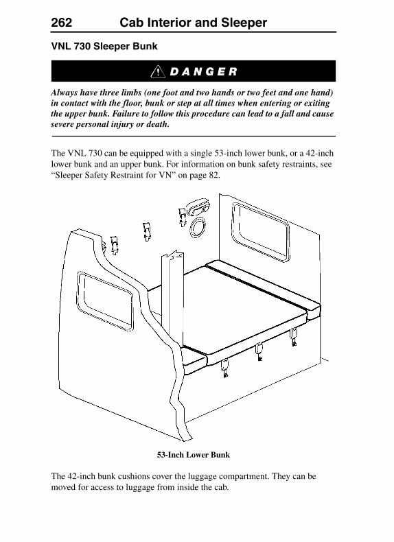
262 Cab Interior and Sleeper
VNL 730 Sleeper Bunk
Always have three limbs (one foot and two hands or two feet and one hand) in contact with the floor, bunk or step at all times when entering or exiting the upper bunk. Failure to follow this procedure can lead to a fall and cause severe personal injury or death.
The VNL 730 can be equipped with a single 53-inch lower bunk, or a 42-inch lower bunk and an upper bunk. For information on bunk safety restraints, see “Sleeper Safety Restraint for VN” on page 82.
53-Inch Lower Bunk
The 42-inch bunk cushions cover the luggage compartment. They can be moved for access to luggage from inside the cab.
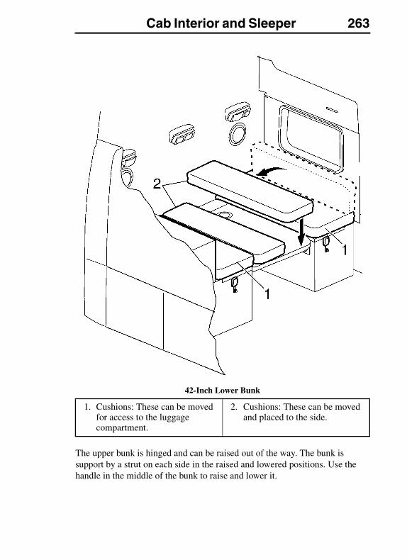
Cab Interior and Sleeper 263
42-Inch Lower Bunk
The upper bunk is hinged and can be raised out of the way. The bunk is support by a strut on each side in the raised and lowered positions. Use the handle in the middle of the bunk to raise and lower it.
1. Cushions: These can be moved for access to the luggage compartment.
2. Cushions: These can be moved and placed to the side.
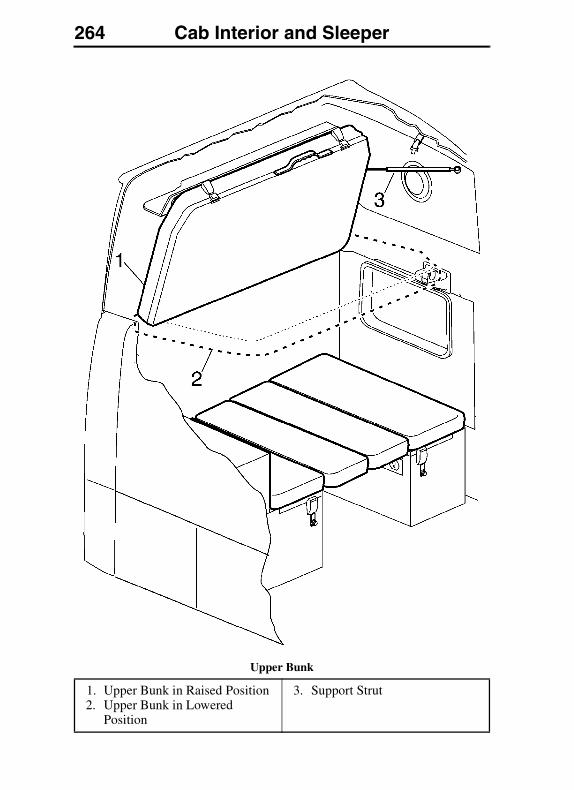
264 Cab Interior and Sleeper
Upper Bunk
1. Upper Bunk in Raised Position2. Upper Bunk in Lowered
Position
3. Support Strut
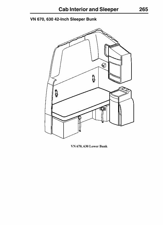
Cab Interior and Sleeper 265
VN 670, 630 42-Inch Sleeper Bunk
VN 670, 630 Lower Bunk
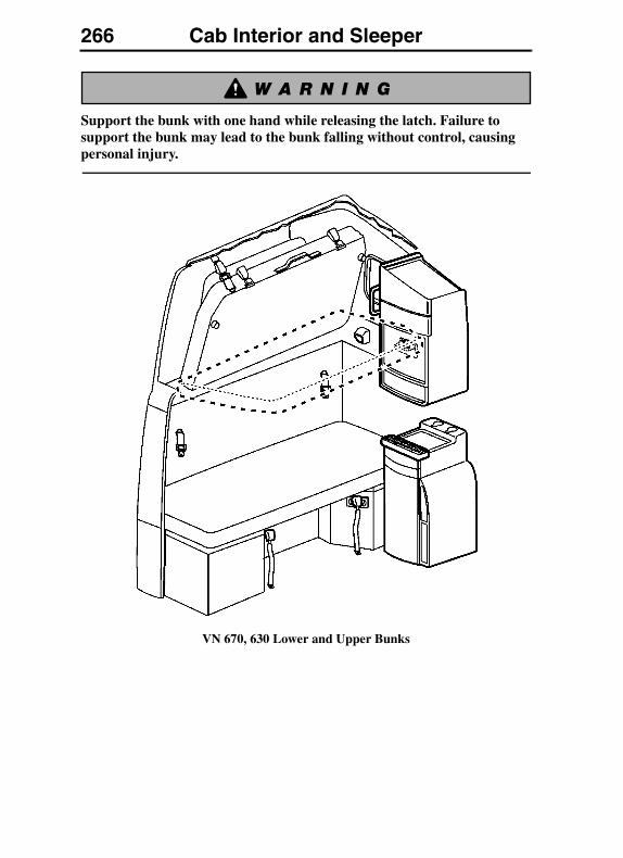
266 Cab Interior and Sleeper
Support the bunk with one hand while releasing the latch. Failure to support the bunk may lead to the bunk falling without control, causing personal injury.
VN 670, 630 Lower and Upper Bunks
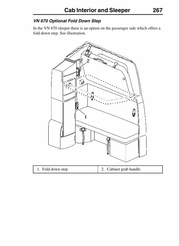
Cab Interior and Sleeper 267
VN 670 Optional Fold Down Step
In the VN 670 sleeper there is an option on the passenger side which offers a fold down step. See illustration.
1. Fold down step 2. Cabinet grab handle
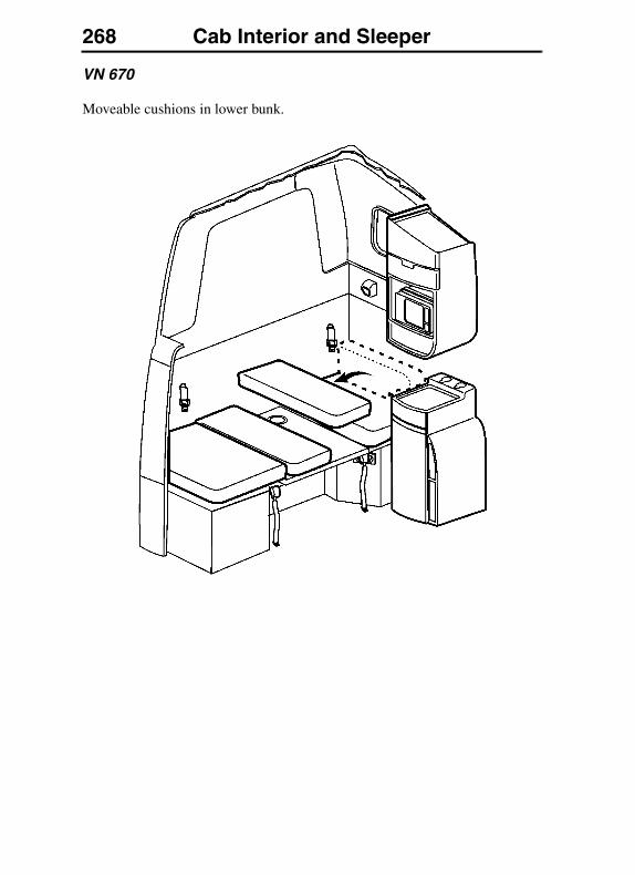
268 Cab Interior and Sleeper
VN 670
Moveable cushions in lower bunk.
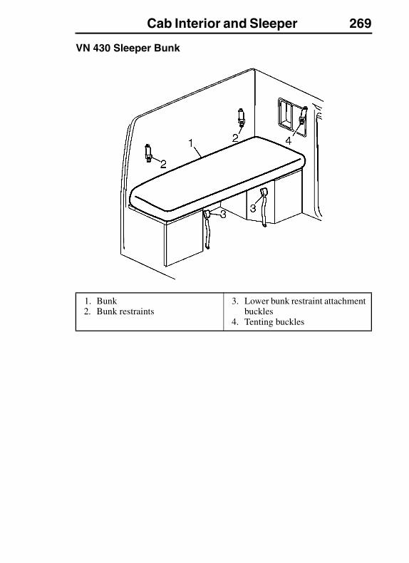
Cab Interior and Sleeper 269
VN 430 Sleeper Bunk
1. Bunk2. Bunk restraints
3. Lower bunk restraint attachment buckles
4. Tenting buckles
270 Cab Interior and Sleeper
Upper Bunk Access VN 780
Always have three limbs (one foot and two hands or two feet and one hand) in contact with the floor, bunk or step at all times when entering or exiting the upper bunk. Failure to follow this procedure can lead to a fall and cause severe personal injury or death.
Support the ladder with one hand while releasing the lock straps. Failure to support the ladder may lead to the ladder falling out, causing injury to leg or foot.
Access to the upper bunk is provided by lowering foldable ladder and securing the ladder into the floor locator (6) and retainer bracket (2) in the upper bunk.
The ladder stored in its collapsed position behind the passenger side cabinet. To release the ladder, unsnap the lock straps. Support the ladder so it does not fall out unaided.
To access the upper bunk, start the climb by grabbing the grab handles with both hands. Place the right foot on the bunk bottom to the right of the cabinet and the left foot on the upper step. Put both feet on the upper step and move the right hand to the upper bunk for support. Swing the upper body into the bunk and sit down.
The grab handle for upper bunk access is located on the cabinet.

Cab Interior and Sleeper 271
1. Ladder in down position2. Retainer3. Grab handle (on optional fixed
bunk, grab handle is not available)
4. Ladder (stored)5. Cabinet grab handle6. Ladder security positioning
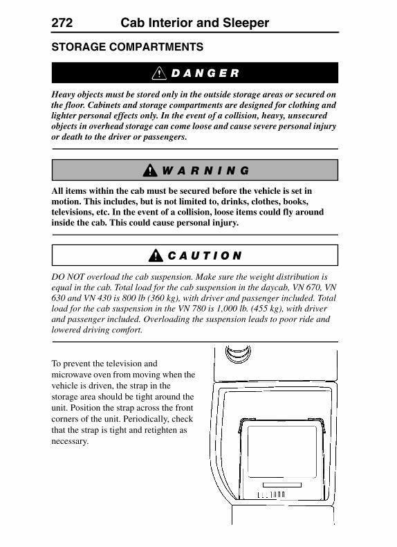
272 Cab Interior and Sleeper
STORAGE COMPARTMENTS
Heavy objects must be stored only in the outside storage areas or secured on the floor. Cabinets and storage compartments are designed for clothing and lighter personal effects only. In the event of a collision, heavy, unsecured objects in overhead storage can come loose and cause severe personal injury or death to the driver or passengers.
All items within the cab must be secured before the vehicle is set in motion. This includes, but is not limited to, drinks, clothes, books, televisions, etc. In the event of a collision, loose items could fly around inside the cab. This could cause personal injury.
DO NOT overload the cab suspension. Make sure the weight distribution is equal in the cab. Total load for the cab suspension in the daycab, VN 670, VN 630 and VN 430 is 800 lb (360 kg), with driver and passenger included. Total load for the cab suspension in the VN 780 is 1,000 lb. (455 kg), with driver and passenger included. Overloading the suspension leads to poor ride and lowered driving comfort.
To prevent the television and microwave oven from moving when the vehicle is driven, the strap in the storage area should be tight around the unit. Position the strap across the front corners of the unit. Periodically, check that the strap is tight and retighten as necessary.
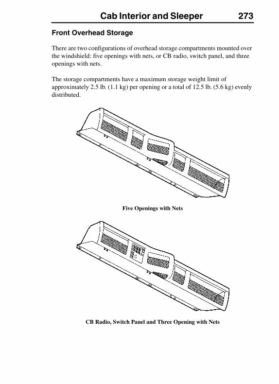
Cab Interior and Sleeper 273
Front Overhead Storage
There are two configurations of overhead storage compartments mounted over the windshield: five openings with nets, or CB radio, switch panel, and three openings with nets.
The storage compartments have a maximum storage weight limit of approximately 2.5 lb. (1.1 kg) per opening or a total of 12.5 lb. (5.6 kg) evenly distributed.
Five Openings with Nets
CB Radio, Switch Panel and Three Opening with Nets
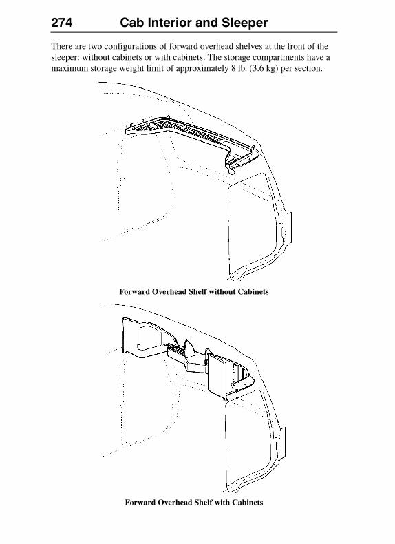
274 Cab Interior and Sleeper
There are two configurations of forward overhead shelves at the front of the sleeper: without cabinets or with cabinets. The storage compartments have a maximum storage weight limit of approximately 8 lb. (3.6 kg) per section.
Forward Overhead Shelf without Cabinets
Forward Overhead Shelf with Cabinets
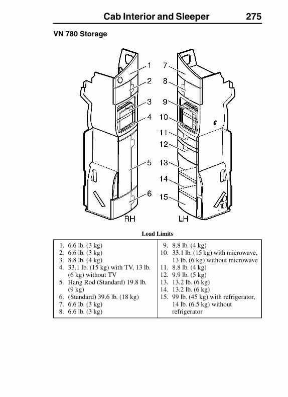
Cab Interior and Sleeper 275
VN 780 Storage
Load Limits
1. 6.6 lb. (3 kg)2. 6.6 lb. (3 kg)3. 8.8 lb. (4 kg)4. 33.1 lb. (15 kg) with TV, 13 lb.
(6 kg) without TV5. Hang Rod (Standard) 19.8 lb.
(9 kg)6. (Standard) 39.6 lb. (18 kg)7. 6.6 lb. (3 kg)8. 6.6 lb. (3 kg)
9. 8.8 lb. (4 kg)10. 33.1 lb. (15 kg) with microwave,
13 lb. (6 kg) without microwave11. 8.8 lb. (4 kg)12. 9.9 lb. (5 kg)13. 13.2 lb. (6 kg)14. 13.2 lb. (6 kg)15. 99 lb. (45 kg) with refrigerator,
14 lb. (6.5 kg) without refrigerator

276 Cab Interior and Sleeper
VN 780 Bunk Storage
1. Storage Bins2. Storage Compartment3. Storage Compartment
4. Exterior Side Storage Compartment
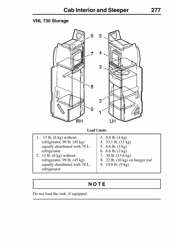
Cab Interior and Sleeper 277
VNL 730 Storage
Load Limits
Do not load the sink, if equipped.
1. 13 lb. (6 kg) without refrigerator, 99 lb. (45 kg) equally distributed with 78 L refrigerator
2. 13 lb. (6 kg) without refrigerator, 99 lb. (45 kg) equally distributed with 78 L refrigerator
3. 8.8 lb. (4 kg)4. 33.1 lb. (15 kg)5. 6.6 lb. (3 kg)6. 6.6 lb. (3 kg)7. 30 lb. (13.6 kg)8. 22 lb. (10 kg) on hanger rod9. 19.8 lb. (9 kg)
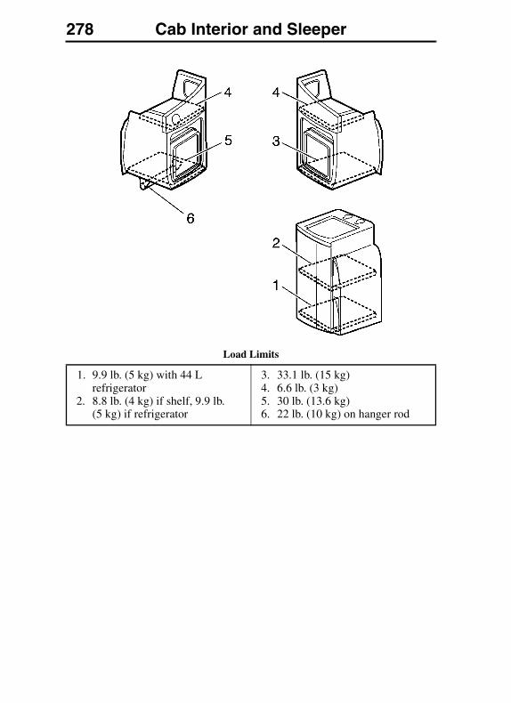
278 Cab Interior and Sleeper
Load Limits
1. 9.9 lb. (5 kg) with 44 L refrigerator
2. 8.8 lb. (4 kg) if shelf, 9.9 lb. (5 kg) if refrigerator
3. 33.1 lb. (15 kg)4. 6.6 lb. (3 kg)5. 30 lb. (13.6 kg)6. 22 lb. (10 kg) on hanger rod
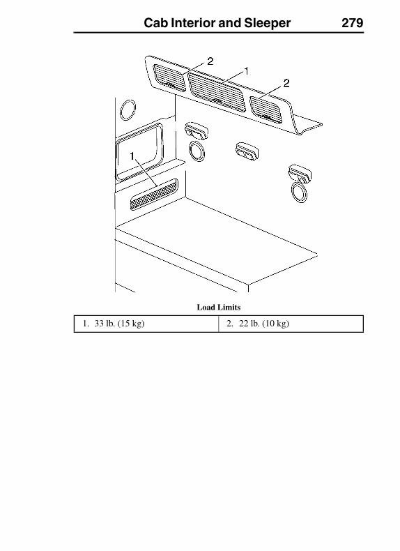
Cab Interior and Sleeper 279
Load Limits
1. 33 lb. (15 kg) 2. 22 lb. (10 kg)
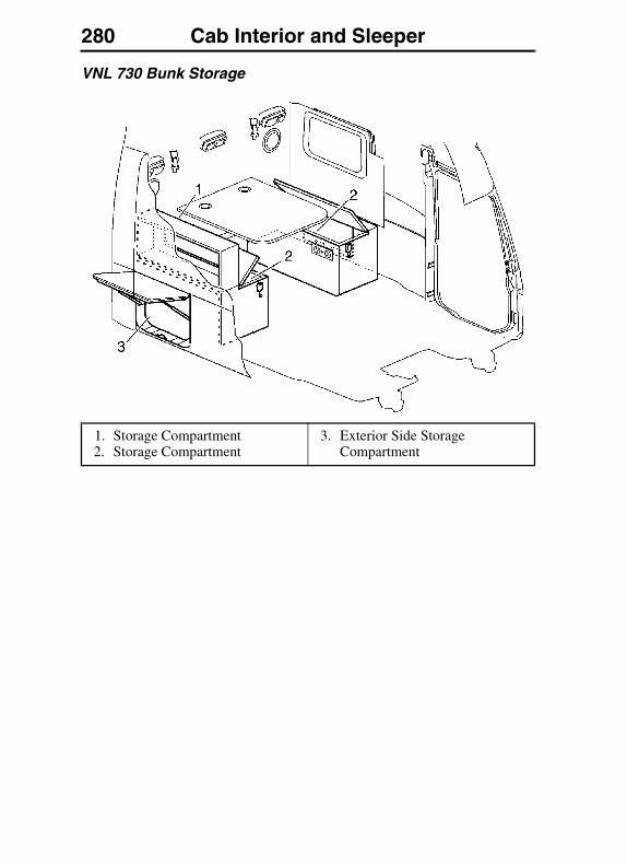
280 Cab Interior and Sleeper
VNL 730 Bunk Storage
1. Storage Compartment2. Storage Compartment
3. Exterior Side Storage Compartment
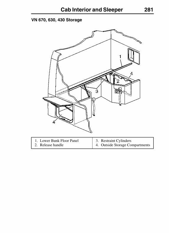
Cab Interior and Sleeper 281
VN 670, 630, 430 Storage
1. Lower Bunk Floor Panel2. Release handle
3. Restraint Cylinders4. Outside Storage Compartments
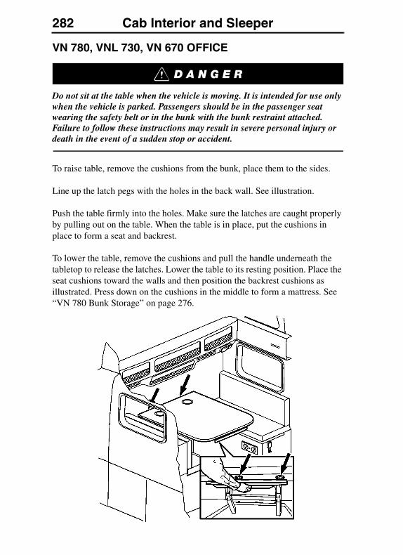
282 Cab Interior and Sleeper
VN 780, VNL 730, VN 670 OFFICE
Do not sit at the table when the vehicle is moving. It is intended for use only when the vehicle is parked. Passengers should be in the passenger seat wearing the safety belt or in the bunk with the bunk restraint attached. Failure to follow these instructions may result in severe personal injury or death in the event of a sudden stop or accident.
To raise table, remove the cushions from the bunk, place them to the sides.
Line up the latch pegs with the holes in the back wall. See illustration.
Push the table firmly into the holes. Make sure the latches are caught properly by pulling out on the table. When the table is in place, put the cushions in place to form a seat and backrest.
To lower the table, remove the cushions and pull the handle underneath the tabletop to release the latches. Lower the table to its resting position. Place the seat cushions toward the walls and then position the backrest cushions as illustrated. Press down on the cushions in the middle to form a mattress. See “VN 780 Bunk Storage” on page 276.
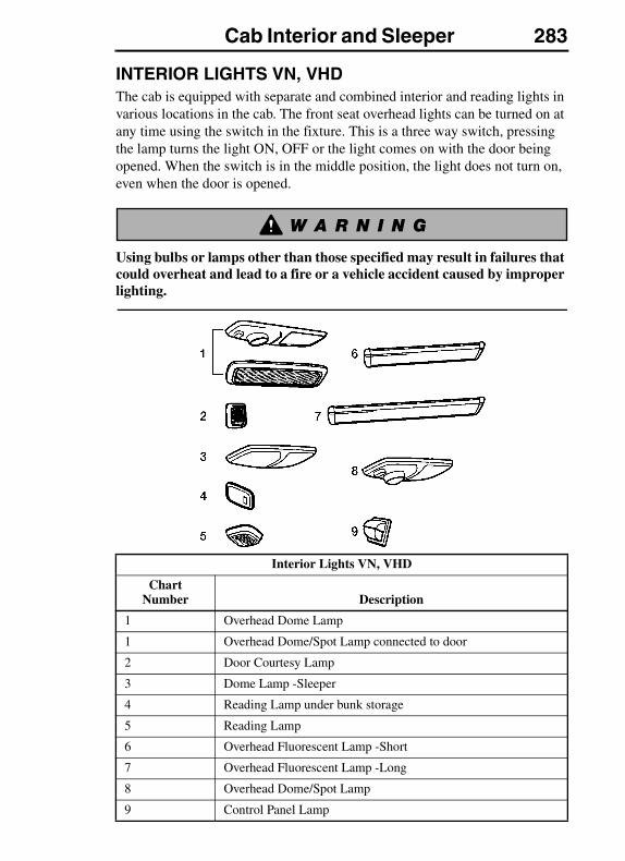
Cab Interior and Sleeper 283
INTERIOR LIGHTS VN, VHDThe cab is equipped with separate and combined interior and reading lights in various locations in the cab. The front seat overhead lights can be turned on at any time using the switch in the fixture. This is a three way switch, pressing the lamp turns the light ON, OFF or the light comes on with the door being opened. When the switch is in the middle position, the light does not turn on, even when the door is opened.
Using bulbs or lamps other than those specified may result in failures that could overheat and lead to a fire or a vehicle accident caused by improper lighting.
Interior Lights VN, VHD
Chart Number Description
1 Overhead Dome Lamp
1 Overhead Dome/Spot Lamp connected to door
2 Door Courtesy Lamp
3 Dome Lamp -Sleeper
4 Reading Lamp under bunk storage
5 Reading Lamp
6 Overhead Fluorescent Lamp -Short
7 Overhead Fluorescent Lamp -Long
8 Overhead Dome/Spot Lamp
9 Control Panel Lamp
284 Cab Interior and Sleeper
For detailed bulb replacement information refer to your Maintenance and Engine Manual. See the “Electrical System Maintenance” section. To prevent short service life, DO NOT touch the glass surface of the replacement bulb.
The lamp assemblies may get warm to the touch, DO NOT cover the lamps with any object.
Most of the vehicle interior lights are activated by pressing on a push button on the lower end of the lamp. There are two external switches for the interior lights, one located on the dash panel, to the immediate left of the steering column, and the other is on the sleeper area control panel.
The red courtesy light comes on when the door is opened. The lens is red to alert oncoming traffic from the rear that the door is open. It is also used during night driving to light up the floor area and steps without distracting the driver with a glaring light.
DO NOT use sleeves of any kind over bulbs in the interior lamps. The bulbs may over heat causing damage to the fixture including possible fire.

Cab Interior and Sleeper 285
The door latch has an internal switch that operates all door-activated lights.
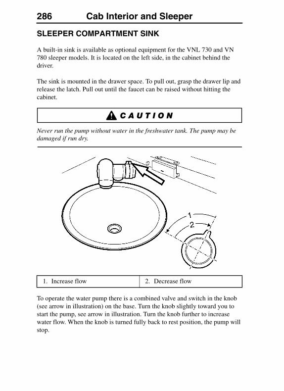
286 Cab Interior and Sleeper
SLEEPER COMPARTMENT SINK
A built-in sink is available as optional equipment for the VNL 730 and VN 780 sleeper models. It is located on the left side, in the cabinet behind the driver.
The sink is mounted in the drawer space. To pull out, grasp the drawer lip and release the latch. Pull out until the faucet can be raised without hitting the cabinet.
Never run the pump without water in the freshwater tank. The pump may be damaged if run dry.
To operate the water pump there is a combined valve and switch in the knob (see arrow in illustration) on the base. Turn the knob slightly toward you to start the pump, see arrow in illustration. Turn the knob further to increase water flow. When the knob is turned fully back to rest position, the pump will stop.
1. Increase flow 2. Decrease flow
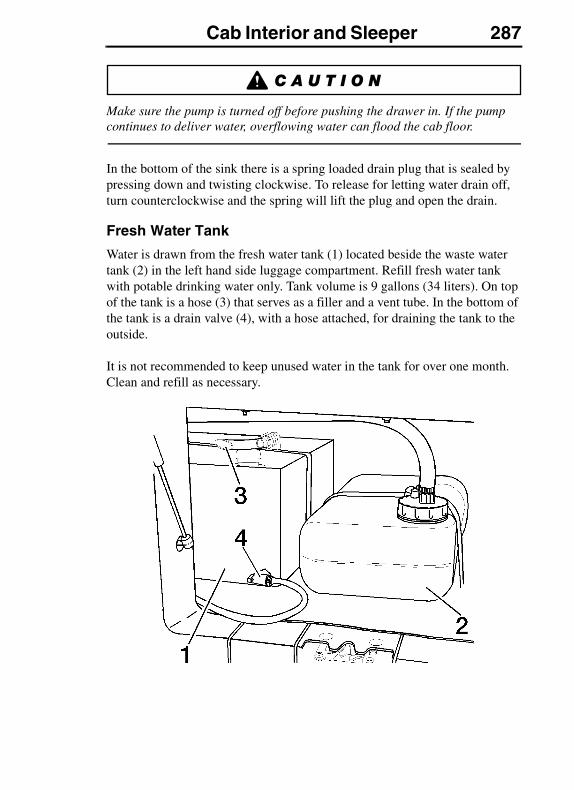
Cab Interior and Sleeper 287
Make sure the pump is turned off before pushing the drawer in. If the pump continues to deliver water, overflowing water can flood the cab floor.
In the bottom of the sink there is a spring loaded drain plug that is sealed by pressing down and twisting clockwise. To release for letting water drain off, turn counterclockwise and the spring will lift the plug and open the drain.
Fresh Water Tank
Water is drawn from the fresh water tank (1) located beside the waste water tank (2) in the left hand side luggage compartment. Refill fresh water tank with potable drinking water only. Tank volume is 9 gallons (34 liters). On top of the tank is a hose (3) that serves as a filler and a vent tube. In the bottom of the tank is a drain valve (4), with a hose attached, for draining the tank to the outside.
It is not recommended to keep unused water in the tank for over one month. Clean and refill as necessary.
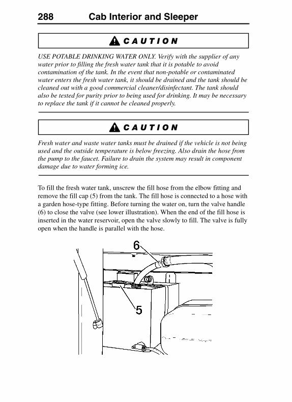
288 Cab Interior and Sleeper
USE POTABLE DRINKING WATER ONLY. Verify with the supplier of any water prior to filling the fresh water tank that it is potable to avoid contamination of the tank. In the event that non-potable or contaminated water enters the fresh water tank, it should be drained and the tank should be cleaned out with a good commercial cleaner/disinfectant. The tank should also be tested for purity prior to being used for drinking. It may be necessary to replace the tank if it cannot be cleaned properly.
Fresh water and waste water tanks must be drained if the vehicle is not being used and the outside temperature is below freezing. Also drain the hose from the pump to the faucet. Failure to drain the system may result in component damage due to water forming ice.
To fill the fresh water tank, unscrew the fill hose from the elbow fitting and remove the fill cap (5) from the tank. The fill hose is connected to a hose with a garden hose-type fitting. Before turning the water on, turn the valve handle (6) to close the valve (see lower illustration). When the end of the fill hose is inserted in the water reservoir, open the valve slowly to fill. The valve is fully open when the handle is parallel with the hose.
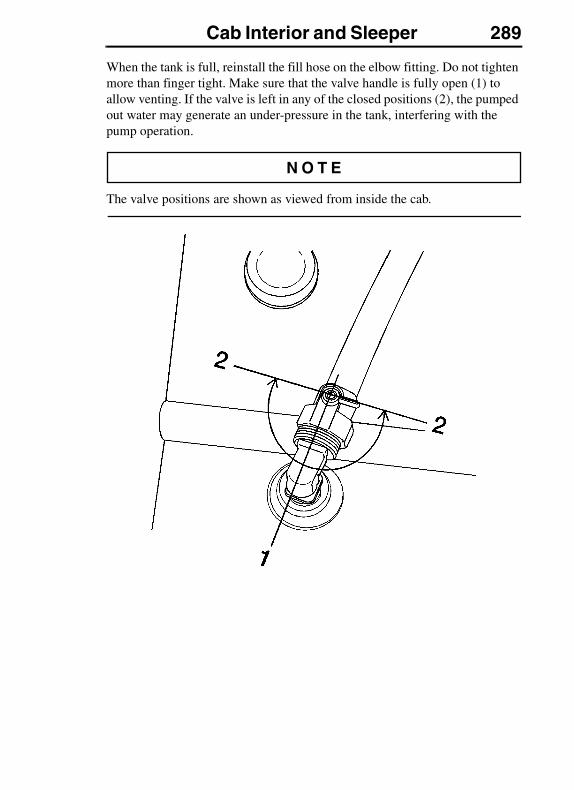
Cab Interior and Sleeper 289
When the tank is full, reinstall the fill hose on the elbow fitting. Do not tighten more than finger tight. Make sure that the valve handle is fully open (1) to allow venting. If the valve is left in any of the closed positions (2), the pumped out water may generate an under-pressure in the tank, interfering with the pump operation.
The valve positions are shown as viewed from inside the cab.

290 Cab Interior and Sleeper
Waste Water Tank
When the water is drained from the sink, it is collected in a waste water tank behind the fresh water tank. Waste water tank volume is 5 gallons (19 liters). The tank is fastened to the floor with a strap that can be easily opened for tank removal.
Before removing the waste water tank, loosen the strap around the tank and unscrew the drain hose from the inlet cap. Carry the tank to an approved dump station and empty by removing the inlet cap and tilting the tank up to let the waste water drain.
Flush the tank with fresh water. Replace the inlet cap, strap the tank into the cab and attach the drain hose.
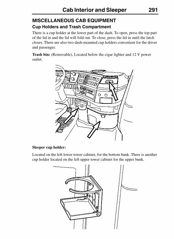
Cab Interior and Sleeper 291
MISCELLANEOUS CAB EQUIPMENTCup Holders and Trash CompartmentThere is a cup holder at the lower part of the dash. To open, press the top part of the lid in and the lid will fold out. To close, press the lid in until the latch closes. There are also two dash-mounted cup holders convenient for the driver and passenger.
Trash bin: (Removable), Located below the cigar lighter and 12 V power outlet.
Sleeper cup holder:
Located on the left lower tower cabinet, for the bottom bunk. There is another cup holder located on the left upper tower cabinet for the upper bunk.
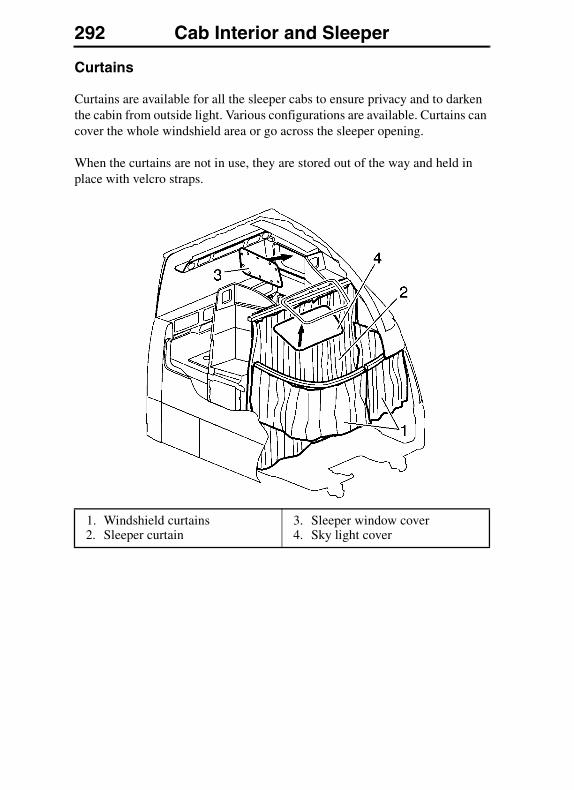
292 Cab Interior and Sleeper
Curtains
Curtains are available for all the sleeper cabs to ensure privacy and to darken the cabin from outside light. Various configurations are available. Curtains can cover the whole windshield area or go across the sleeper opening.
When the curtains are not in use, they are stored out of the way and held in place with velcro straps.
1. Windshield curtains2. Sleeper curtain
3. Sleeper window cover4. Sky light cover

Cab Interior and Sleeper 293
Covers for the VN 670 are to be stored in a rolled-up position in the opening behind the cabinet.
The covers for the VN 780 side windows are stored behind the backrest cushions. All covers are put on with snap buttons that are on the cover and window rim, with the exception of the sky light cover.
VNL 730 Curtains
1. Windshield curtains 2. Sleeper curtains
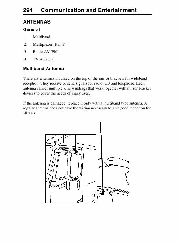
294 Communication and EntertainmentCOMMUNICATION AND ENTERTAINMENT
ANTENNAS
General
1. Multiband
2. Multiplexer (Rami)
3. Radio AM/FM
4. TV Antenna
Multiband Antenna
There are antennas mounted on the top of the mirror brackets for wideband reception. They receive or send signals for radio, CB and telephone. Each antenna carries multiple wire windings that work together with mirror bracket devices to cover the needs of many uses.
If the antenna is damaged, replace it only with a multiband type antenna. A regular antenna does not have the wiring necessary to give good reception for all uses.
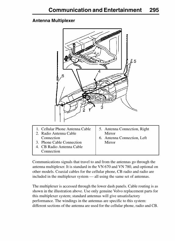
Communication and Entertainment 295
Antenna Multiplexer
Communications signals that travel to and from the antennas go through the antenna multiplexer. It is standard in the VN 670 and VN 780, and optional on other models. Coaxial cables for the cellular phone, CB radio and radio are included in the multiplexer system — all using the same set of antennas.
The multiplexer is accessed through the lower dash panels. Cable routing is as shown in the illustration above. Use only genuine Volvo replacement parts for this multiplexer system; standard antennas will give unsatisfactory performance. The windings in the antennas are specific to this system: different sections of the antenna are used for the cellular phone, radio and CB.
1. Cellular Phone Antenna Cable2. Radio Antenna Cable
Connection3. Phone Cable Connection4. CB Radio Antenna Cable
Connection
5. Antenna Connection, Right Mirror
6. Antenna Connection, Left Mirror

296 Communication and Entertainment
The location of the CB may vary. CB connections can be located either in the dash or overhead storage area, depending on vehicle options. See “Front Overhead Storage” on page 273.
STEREO/RADIO
Stereo
The radio is mounted in the right hand side of the dash. Several models are available, from a basic unit to top of the line.
Depending on the model, there are some important features built into the unit. Take the time to read the manufacturer's manual to be able to operate functions such as radio wake-up alarm, snooze function and theft-deterrent coding.
TELEVISION
All items within the cab must be secured before the vehicle is set in motion. This includes, but is not limited to, drinks, clothes, books, televisions, etc. In the event of a sudden stop or collision, loose items could fly around inside the cab. This could cause personal injury.
The VN 780, VN 730, VN 670 and VN 630 are already equipped for TV with a pre-installed antenna. The TV should be installed in the passenger side cabinet where there is a standard 12 V connection or an optional 120 V connection.
To prevent the TV set from moving when the vehicle is driven, the strap in the TV storage area should be tight around the set. Position the strap across the front corners of the TV.
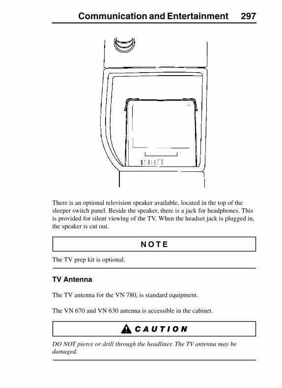
Communication and Entertainment 297
There is an optional television speaker available, located in the top of the sleeper switch panel. Beside the speaker, there is a jack for headphones. This is provided for silent viewing of the TV. When the headset jack is plugged in, the speaker is cut out.
The TV prep kit is optional.
TV Antenna
The TV antenna for the VN 780, is standard equipment.
The VN 670 and VN 630 antenna is accessible in the cabinet.
DO NOT pierce or drill through the headliner. The TV antenna may be damaged.
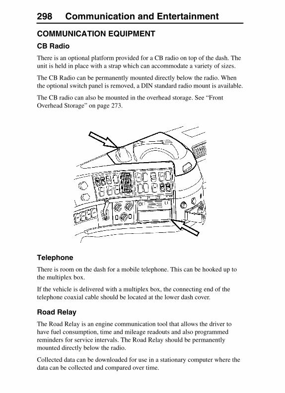
298 Communication and Entertainment
COMMUNICATION EQUIPMENT
CB Radio
There is an optional platform provided for a CB radio on top of the dash. The unit is held in place with a strap which can accommodate a variety of sizes.
The CB Radio can be permanently mounted directly below the radio. When the optional switch panel is removed, a DIN standard radio mount is available.
The CB radio can also be mounted in the overhead storage. See “Front Overhead Storage” on page 273.
Telephone
There is room on the dash for a mobile telephone. This can be hooked up to the multiplex box.
If the vehicle is delivered with a multiplex box, the connecting end of the telephone coaxial cable should be located at the lower dash cover.
Road Relay
The Road Relay is an engine communication tool that allows the driver to have fuel consumption, time and mileage readouts and also programmed reminders for service intervals. The Road Relay should be permanently mounted directly below the radio.
Collected data can be downloaded for use in a stationary computer where the data can be collected and compared over time.

Fuel Economy Driving 299FUEL ECONOMY DRIVING
FUEL ECONOMY
General
The absolute fuel consumption (counted in miles per US gallon or liters per 100 kilometers) is determined by a large number of circumstances which can be related to one of the following main areas:
1. Build specification and equipment
2. Service and maintenance
3. External environment
4. Driving habits
Due to these factors, fuel consumption can vary considerably within what is called “normal fuel consumption.” Fuel consumption can vary from over 10 mpg (24 L/100 km) when driving empty on a nice and dry summer road to 3.5 mpg (67 L/100 km) while driving with maximum permitted GVW, with vehicle and trailer, on a hilly and slushy winter road.
Build Specification and Equipment
Whenever a vehicle is used for transportation, its build specification, equipment and gross vehicle weight have a decisive effect on both fuel consumption and performance. The factors which have the greatest influence on fuel consumption are primarily: driveline combination, height of trailer or superstructure, use of air fairings, tire type, number of wheels, gross vehicle weight, and accessories.
Driveline Combination
Engine, transmission and final drive must be selected in such a way that the engine can operate within the economic speed range at normal driving speed. This range is defined as where the engine makes the best use of the energy content of the diesel fuel.
A poorly selected rear axle ratio, which results in the engine speed being constantly above the optimum speed, will increase fuel consumption.
Tires
Heavy duty threaded tires increase rolling resistance considerably. For long haul, choose a smoother, ribbed type tire. Choose a lugged type tire only when the added traction in mud and snow is needed.
The number of wheels (axles) has a direct effect on the rolling resistance and, thereby, the fuel consumption. For volume and/or low weight transports, the use of a 4x2 instead of a 6x4 should be considered.
300 Fuel Economy Driving
Gross Vehicle Weight
The gross vehicle weight of a vehicle combination has a large impact on the rolling resistance.
Accessories
As a rule, accessories such as roof rack, advertising signs, bug screens, exposed air horns, etc., have a negative effect on fuel consumption.
Service and Maintenance
A modern heavy-duty vehicle requires regular and preventive maintenance to ensure that all its components function as they should. Use the recommended preventive maintenance (PM) program that Volvo Trucks North America has developed for the vehicles. This ensures optimal energy efficiency from all components that are important to fuel consumption.
Tires
If the tire pressure is too low, the rolling resistance increases and, thereby, increases the fuel consumption. The overall economy is also affected as tire wear increases considerably.
Brakes
Dragging brakes increase fuel consumption. They should be checked regularly. It is important that the release action of the air valves is fast and that the moving parts of the wheel brakes are checked for good adjustment and operation.
Axles
An axle out of alignment increases rolling resistance. Regularly check the front wheel alignment and axles on both the tractor and trailer/semi-trailer. If they are correct, there will be less rolling resistance and, therefore, lower fuel consumption.
A good sign of an axle or wheel out of alignment is uneven tire wear. Check the tires often.

Fuel Economy Driving 301
Engine
Faulty or incorrectly adjusted engine components increase fuel consumption. The list below gives some typical components that can influence fuel consumption:
� Blocked (on the outside) charge air cooler/radiator package
� Faulty thermostat
� Blocked fuel filters
� Blocked air intake filter
� Faulty injectors
� Dirty turbocharger
� Air in fuel system
� Faulty fuel supply pump
� Faulty fuel relief valve
� Faulty fan thermostat/clutch
External EnvironmentUnder unfavorable conditions, the external environment can have a negative effect on fuel consumption. This can be broken down into two main groups: weather and wind; and the nature of the roads. Rain, snow, icy conditions and headwinds have a large negative impact on fuel economy, as do hilly roads and uneven road surfaces.
HeadwindsHeadwinds have a large negative impact on fuel consumption. With tailwinds, fuel saving is only marginal.
Air TemperatureLow ambient temperature contributes to increased fuel consumption.
Rain, Snow and Road SurfaceA wet road surface increases rolling resistance and, thereby, fuel consumption. Slush will increase consumption even more. In certain cases, the surface structure of the road can also have a negative effect on fuel consumption.
GradientsA hilly road with many bends demands a higher output from the engine. The difference between flat, straight roads and hilly, winding roads can amount to as much as a 50 percent increase in fuel consumption.
When choosing your route, avoid hills, rough roads and frequent stops.
302 Fuel Economy Driving
Driving Habits
The way in which a vehicle is being driven is the one factor which has the greatest influence on fuel consumption. Correct driving saves fuel and reduces vehicle wear. To achieve optimal running economy, the driver should always remember to:
� Start the engine correctly (especially important in winter season)
� Maintain an even and correct speed
� Keep the engine at its optimum speed range
� Use the correct uphill and downhill driving technique.
Starting the Engine
Start the engine according to the instructions in the Operator's Manual of the engine manufacturer (for a Volvo engine, see “Starting the Engine” on page 303). A proper start, especially during the cold season, saves fuel and reduces engine wear.
Sluggish lube oil in the engine makes cold starting more difficult. Therefore, it is important to always use engine oil with the correct viscosity. (For the sake of the overall fuel economy, it is also important to have the right viscosity of transmission and rear axle oils).
Avoid High Engine Speeds
High engine speeds mean high fuel consumption. “Jerky” driving also increases fuel consumption when the vehicle is constantly accelerated and slowed down. Avoid a higher consumption by steady, even driving.
Refer to each engine manufacturer's operator's manual for information on the engine's optimum operating range.
Hill Driving Technique
Use the inertia of the vehicle to go over the crest of a hill under reduced power. Use gravity to help with acceleration when going down the hill. Build up speed before reaching the next uphill.
High Speed
With increasing speed comes an increasing wind resistance that negatively affects fuel consumption.
Engine Start and Operation 303ENGINE START AND OPERATION
STARTING THE ENGINE
Start Procedure
For cold weather starting, see “Cold Weather Start and Operation” on page 307.
These starting and operating procedures should be followed for all engines. For more detailed information about design and function on a non-Volvo engine, read the Operator's Manual from the engine manufacturer.
Before starting the engine, see “Instruments and Controls” (starting on “Dash Overview VN” on page 106) for detailed information on how the gauges and telltales work.
DO NOT use ether or other combustible starting aids in any Volvo engine. The Volvo engine is equipped with a preheater, introduction of ether or similar starting aids could cause a fire or explosion resulting in severe property damage, serious personal injury or death.
304 Engine Start and Operation
Never operate the starter without first placing the transmission in neutral or depressing the clutch pedal. Failure to follow these instructions may result in the unintentional movement of the vehicle resulting in property damage, personal injury or death.
1. Before starting the engine, perform the engine pre-trip inspection and daily maintenance checks in “Pre-Trip Inspection and Daily Maintenance” starting on “General” on page 56.
2. Make sure the parking brakes are engaged.
3. Place the transmission in neutral or depress the clutch pedal.
DO NOT crank the engine for more than 30 seconds at a time; wait two minutes after each try to allow the starter to cool. Failure to follow these instructions could cause starter damage.
Some starters are equipped with an optional thermostat. If overcranking occurs, the thermostat breaks the electrical circuit to the starter motor until the motor has cooled.
4. Turn on the ignition with the switch key (see “Ignition Switch” on page 306 for ignition switch information). Some telltales will come on in a routine check that shows the bulbs and systems are OK.
If any of the telltales stay lit, that function of the vehicle may not be operable. DO NOT operate the vehicle until the problem is repaired.
5. Turn the key to the start position. Release key as soon as the engine has started. For the Volvo engine, the preheater can be engaged to help starting in cold temperatures. For switch function, see “Ignition Switch” on page 306.
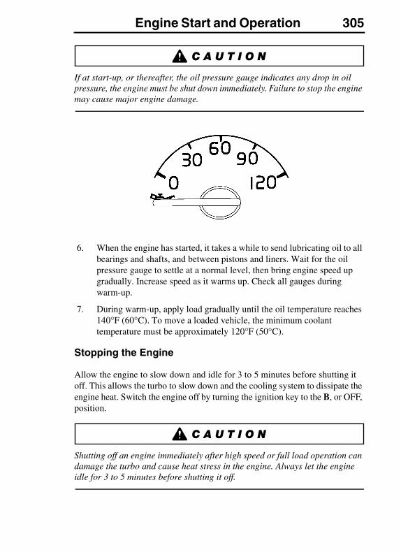
Engine Start and Operation 305
If at start-up, or thereafter, the oil pressure gauge indicates any drop in oil pressure, the engine must be shut down immediately. Failure to stop the engine may cause major engine damage.
6. When the engine has started, it takes a while to send lubricating oil to all bearings and shafts, and between pistons and liners. Wait for the oil pressure gauge to settle at a normal level, then bring engine speed up gradually. Increase speed as it warms up. Check all gauges during warm-up.
7. During warm-up, apply load gradually until the oil temperature reaches 140°F (60°C). To move a loaded vehicle, the minimum coolant temperature must be approximately 120°F (50°C).
Stopping the Engine
Allow the engine to slow down and idle for 3 to 5 minutes before shutting it off. This allows the turbo to slow down and the cooling system to dissipate the engine heat. Switch the engine off by turning the ignition key to the B, or OFF, position.
Shutting off an engine immediately after high speed or full load operation can damage the turbo and cause heat stress in the engine. Always let the engine idle for 3 to 5 minutes before shutting it off.
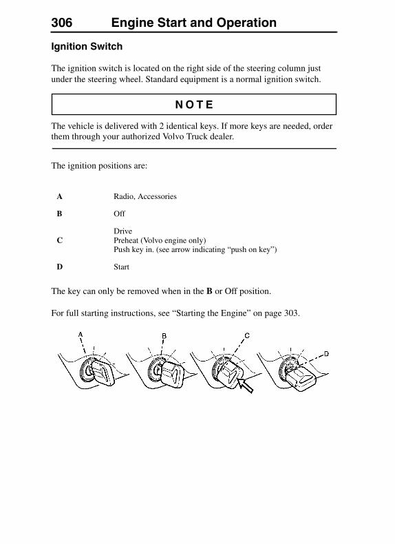
306 Engine Start and Operation
Ignition Switch
The ignition switch is located on the right side of the steering column just under the steering wheel. Standard equipment is a normal ignition switch.
The vehicle is delivered with 2 identical keys. If more keys are needed, order them through your authorized Volvo Truck dealer.
The ignition positions are:
The key can only be removed when in the B or Off position.
For full starting instructions, see “Starting the Engine” on page 303.
A Radio, Accessories
B Off
CDrivePreheat (Volvo engine only)Push key in. (see arrow indicating “push on key”)
D Start
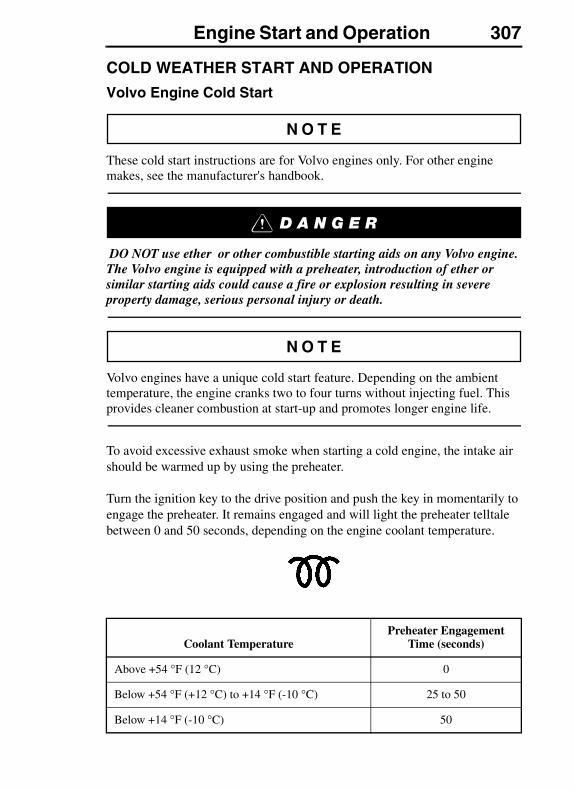
Engine Start and Operation 307
COLD WEATHER START AND OPERATION
Volvo Engine Cold Start
These cold start instructions are for Volvo engines only. For other engine makes, see the manufacturer's handbook.
DO NOT use ether or other combustible starting aids on any Volvo engine. The Volvo engine is equipped with a preheater, introduction of ether or similar starting aids could cause a fire or explosion resulting in severe property damage, serious personal injury or death.
Volvo engines have a unique cold start feature. Depending on the ambient temperature, the engine cranks two to four turns without injecting fuel. This provides cleaner combustion at start-up and promotes longer engine life.
To avoid excessive exhaust smoke when starting a cold engine, the intake air should be warmed up by using the preheater.
Turn the ignition key to the drive position and push the key in momentarily to engage the preheater. It remains engaged and will light the preheater telltale between 0 and 50 seconds, depending on the engine coolant temperature.
Coolant TemperaturePreheater Engagement
Time (seconds)
Above +54 °F (12 °C) 0
Below +54 °F (+12 °C) to +14 °F (-10 °C) 25 to 50
Below +14 °F (-10 °C) 50
308 Engine Start and Operation
When the engine has started, the heater will automatically be reengaged for the same time length as the preheater.
The preheater will always be engaged when the key is in the drive position and pushed in, independent of coolant.
Engines Without Preheater
Engines not equipped may, depending on coolant temperature, take longer to start. If this should happen, DO NOT release the ignition key until the engine has started (while still observing the 30 second maximum cranking time).
Ether Start
DO NOT use ether or other combustible starting aids on any Volvo engine. The Volvo engine is equipped with a preheater, introduction of ether or similar starting aids could cause a fire or explosion resulting in severe property damage, serious personal injury or death.
DO NOT breathe the ether fumes. Breathing ether fumes could result in personal injury or death.
If using a cold start system, make sure to read and follow the manufacturer's instructions regarding its use, handling and storage. Many starting fluids are sold in capsules or pressure cans and improper usage can be dangerous, resulting in personal injury or death.
Ether allows combustion with lower cylinder temperatures. A hand-held spray can for injecting ether through the engine air intake system will usually provide quick starting to as low as -10°F (-23°C). Below this temperature, a permanently installed system for injecting a combustible vapor directly into the intake manifold is necessary.
Only inject ether vapors when the engine is cranking. Use it sparingly! Excessive ether use can cause piston and ring damage.
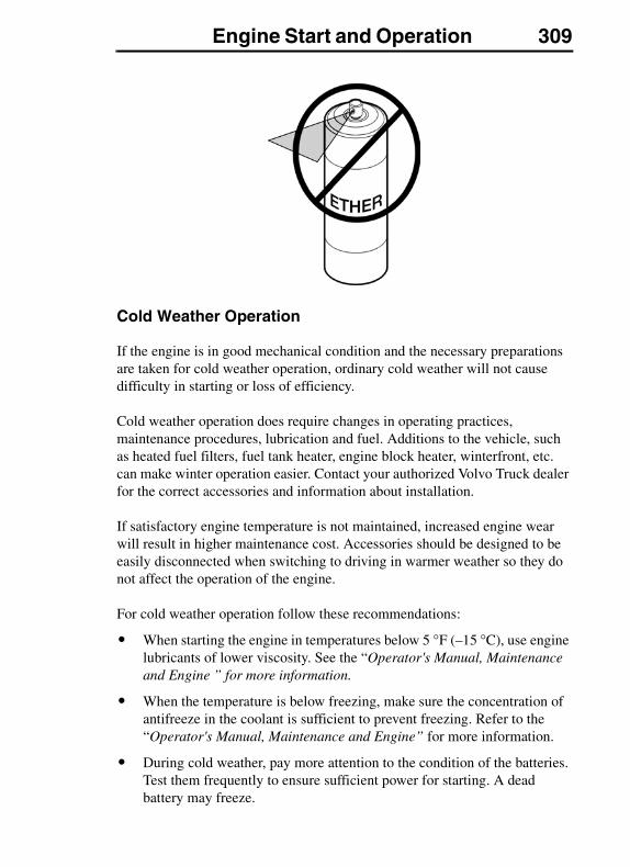
Engine Start and Operation 309
Cold Weather Operation
If the engine is in good mechanical condition and the necessary preparations are taken for cold weather operation, ordinary cold weather will not cause difficulty in starting or loss of efficiency.
Cold weather operation does require changes in operating practices, maintenance procedures, lubrication and fuel. Additions to the vehicle, such as heated fuel filters, fuel tank heater, engine block heater, winterfront, etc. can make winter operation easier. Contact your authorized Volvo Truck dealer for the correct accessories and information about installation.
If satisfactory engine temperature is not maintained, increased engine wear will result in higher maintenance cost. Accessories should be designed to be easily disconnected when switching to driving in warmer weather so they do not affect the operation of the engine.
For cold weather operation follow these recommendations:
� When starting the engine in temperatures below 5 °F (–15 °C), use engine lubricants of lower viscosity. See the “Operator's Manual, Maintenance and Engine ” for more information.
� When the temperature is below freezing, make sure the concentration of antifreeze in the coolant is sufficient to prevent freezing. Refer to the “Operator's Manual, Maintenance and Engine” for more information.
� During cold weather, pay more attention to the condition of the batteries. Test them frequently to ensure sufficient power for starting. A dead battery may freeze.
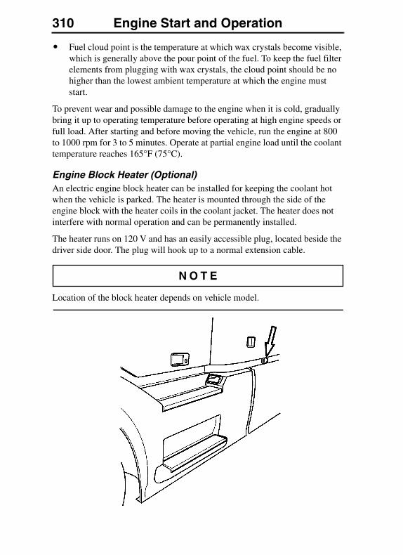
310 Engine Start and Operation
� Fuel cloud point is the temperature at which wax crystals become visible, which is generally above the pour point of the fuel. To keep the fuel filter elements from plugging with wax crystals, the cloud point should be no higher than the lowest ambient temperature at which the engine must start.
To prevent wear and possible damage to the engine when it is cold, gradually bring it up to operating temperature before operating at high engine speeds or full load. After starting and before moving the vehicle, run the engine at 800 to 1000 rpm for 3 to 5 minutes. Operate at partial engine load until the coolant temperature reaches 165°F (75°C).
Engine Block Heater (Optional)An electric engine block heater can be installed for keeping the coolant hot when the vehicle is parked. The heater is mounted through the side of the engine block with the heater coils in the coolant jacket. The heater does not interfere with normal operation and can be permanently installed.
The heater runs on 120 V and has an easily accessible plug, located beside the driver side door. The plug will hook up to a normal extension cable.
Location of the block heater depends on vehicle model.
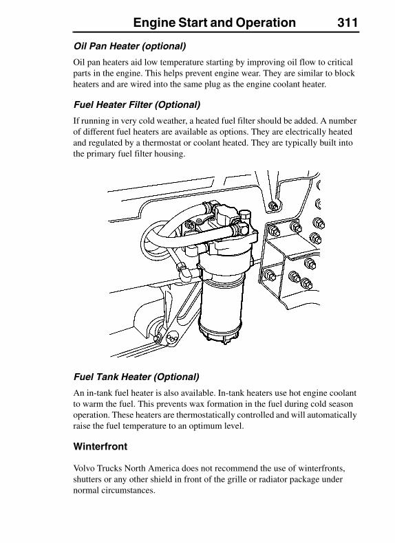
Engine Start and Operation 311
Oil Pan Heater (optional)
Oil pan heaters aid low temperature starting by improving oil flow to critical parts in the engine. This helps prevent engine wear. They are similar to block heaters and are wired into the same plug as the engine coolant heater.
Fuel Heater Filter (Optional)
If running in very cold weather, a heated fuel filter should be added. A number of different fuel heaters are available as options. They are electrically heated and regulated by a thermostat or coolant heated. They are typically built into the primary fuel filter housing.
Fuel Tank Heater (Optional)
An in-tank fuel heater is also available. In-tank heaters use hot engine coolant to warm the fuel. This prevents wax formation in the fuel during cold season operation. These heaters are thermostatically controlled and will automatically raise the fuel temperature to an optimum level.
Winterfront
Volvo Trucks North America does not recommend the use of winterfronts, shutters or any other shield in front of the grille or radiator package under normal circumstances.
312 Engine Start and Operation
Today's electronically controlled engines are designed to operate in cold temperatures without a winterfront. These devices, if not used properly, can cause higher exhaust temperatures, power loss, excessive fan usage, failure of the charge-air-cooler and a reduction in fuel economy.
Winterfronts are properly used in the wintertime during very cold weather with sustained temperatures below -15°F (-25°C). In these cases, coolant and inlet manifold temperatures must also be carefully monitored and controlled.
Failure to remove the winterfront when temperatures go above -15°F (-25°C) could cause severe damage to engine, charge-air-cooler and/or loss of fuel economy.
If a winterfront is used, it must conform to these specifications:
� The grille coverage should be such that airflow through to the charge-air-cooler is at a uniform rate over the entire area. This means that a single, small opening in the winterfront is not acceptable.
� Air passage must be distributed evenly across the grille and no more than 85% can be covered.
Please see your authorized Volvo Truck dealer for Volvo recommended winterfronts.
If there is engine or related damage that can be traced to an improperly used winterfront, the warranty is no longer valid for those parts.
Engine Start and Operation 313
ENGINE OPERATION
General
Proper operation, driving techniques and maintenance are key factors in obtaining the maximum life and economy from a modern turbocharged diesel engine. This section has operational information about the components that make up the engine. For the best operation economy, see “Fuel Economy” on page 299.
When changing gears, avoid lugging to extend engine life. When the engine is operating at full throttle and maximum governed speed cannot be reached or maintained, the engine is lugging. When approaching a hill requiring more power, it is necessary to downshift the transmission as the vehicle goes into the grade. Accelerating to the governed engine speed will give additional power at approximately the same road speed. For shifting instructions, see the transmission manufacturer's Operator's Manual.
Always start moving the load in a gear low enough so that the engine can be accelerated to the governed speed. Then shift to the next gear as the engine decelerates. For loaded vehicles, do not skip a gear or lug the engine while getting up to cruising speed. For empty or light loads, it is permissible to skip gears.
When operating on a level highway or at cruising speed, hold the engine speed at approximately 1400 to 1600 rpm for large displacement engines to achieve power and economical fuel consumption.
The operator should understand the operating characteristics of the engine the vehicle is equipped with. Modern diesel engines have maximum torques at much lower engine speeds than in the past. As such, these engines are designed to perform satisfactorily at a lower speed. New transmissions with wide ratio steps between gears demand the use of these engines.
Excessive exhaust smoke may be due to the type of fuel used, a restricted air cleaner, a malfunctioning fuel system or the way the vehicle is operated. Shift gears and increase or decrease the engine speed as necessary to obtain the engine speed/transmission gear combination which will prevent smoking. Excessive smoke indicates wasted fuel which creates carbon deposits in the engine and turbocharger. This causes excessive engine wear and oil consumption. Excessive smoke not only pollutes the atmosphere but can also cause shortened exhaust system life.
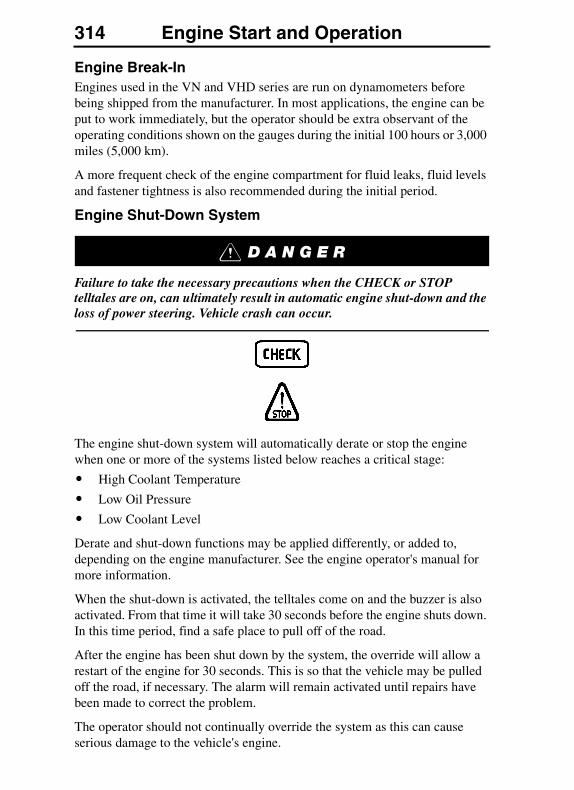
314 Engine Start and Operation
Engine Break-InEngines used in the VN and VHD series are run on dynamometers before being shipped from the manufacturer. In most applications, the engine can be put to work immediately, but the operator should be extra observant of the operating conditions shown on the gauges during the initial 100 hours or 3,000 miles (5,000 km).
A more frequent check of the engine compartment for fluid leaks, fluid levels and fastener tightness is also recommended during the initial period.
Engine Shut-Down System
Failure to take the necessary precautions when the CHECK or STOP telltales are on, can ultimately result in automatic engine shut-down and the loss of power steering. Vehicle crash can occur.
The engine shut-down system will automatically derate or stop the engine when one or more of the systems listed below reaches a critical stage:
� High Coolant Temperature
� Low Oil Pressure
� Low Coolant Level
Derate and shut-down functions may be applied differently, or added to, depending on the engine manufacturer. See the engine operator's manual for more information.
When the shut-down is activated, the telltales come on and the buzzer is also activated. From that time it will take 30 seconds before the engine shuts down. In this time period, find a safe place to pull off of the road.
After the engine has been shut down by the system, the override will allow a restart of the engine for 30 seconds. This is so that the vehicle may be pulled off the road, if necessary. The alarm will remain activated until repairs have been made to correct the problem.
The operator should not continually override the system as this can cause serious damage to the vehicle's engine.
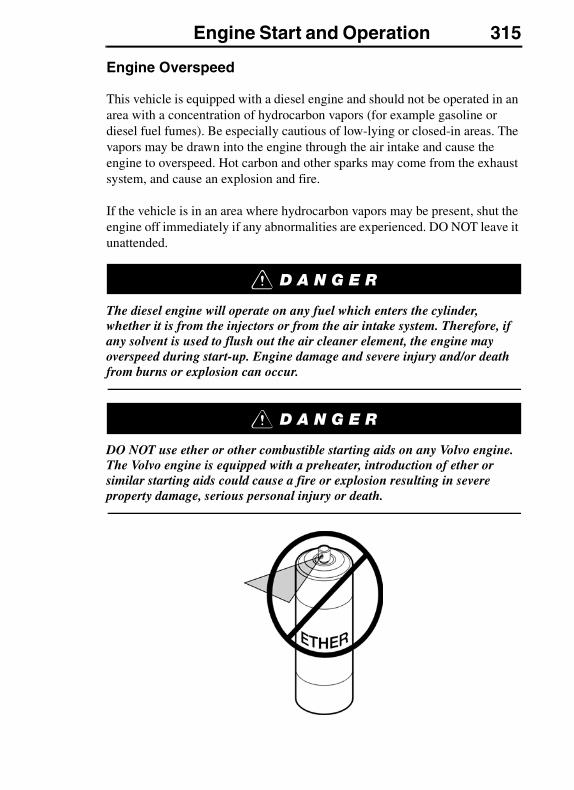
Engine Start and Operation 315
Engine Overspeed
This vehicle is equipped with a diesel engine and should not be operated in an area with a concentration of hydrocarbon vapors (for example gasoline or diesel fuel fumes). Be especially cautious of low-lying or closed-in areas. The vapors may be drawn into the engine through the air intake and cause the engine to overspeed. Hot carbon and other sparks may come from the exhaust system, and cause an explosion and fire.
If the vehicle is in an area where hydrocarbon vapors may be present, shut the engine off immediately if any abnormalities are experienced. DO NOT leave it unattended.
The diesel engine will operate on any fuel which enters the cylinder, whether it is from the injectors or from the air intake system. Therefore, if any solvent is used to flush out the air cleaner element, the engine may overspeed during start-up. Engine damage and severe injury and/or death from burns or explosion can occur.
DO NOT use ether or other combustible starting aids on any Volvo engine. The Volvo engine is equipped with a preheater, introduction of ether or similar starting aids could cause a fire or explosion resulting in severe property damage, serious personal injury or death.
316 Engine Start and Operation
Idling
All VN and VHD model engines are electronically governed engines. The idle speed is pre-programmed from the manufacturer. Low idle speed is adjustable within certain limits (for most engines between 600 to 750 rpm). See “Low Idle Adjustment” on page 317 for more information.
The common belief that idling a diesel engine causes no engine damage is wrong. Idling produces sulfuric acid, which breaks down the oil and eats into bearings, rings, valve stems and engine surfaces.
Avoid excessive idling. If the vehicle is parked for more than 5 minutes, stop the engine. An engine can burn from 0.75 to 1.5 gallons (3 to 5.5 liters) of fuel per hour while idling. During long engine idling periods, the engine coolant temperature may fall below the normal operating range. Volvo engines are equipped with a warm holding device (EPG = Exhaust Pressure Governor) to keep engine to normal operating temperature to prevent incomplete combustion, even at idle. Incomplete combustion of fuel during the warm-up period can cause dilution of the oil in the crankcase, formation of lacquer or gummy deposits on the valves, pistons and rings, and rapid accumulation of sludge in the engine.

Engine Start and Operation 317
Low Idle Adjustment
Before setting the idle, apply the parking brakes and place the transmission in neutral. Failure to do so can result in unexpected vehicle movement and can cause serious personal injury or death.
If the engine coolant temperature is above 122 °F (50 °C), the vehicle is stationary (engine running; accelerator released; parking brake on) and the PTO not engaged, the engine low idle speed can be adjusted with the use of the cruise control function.
1. Set the cruise control switch to the ON position.
2. Depress the foot brake pedal. Hold it down during the entire procedure.
3. Move the cruise control switch to the RESUME position and hold it there for four seconds. Release the switch. The engine speed will drop to the default low idle (Volvo engines), or a slight drop in idle speed will occur (Cummins).
4. The idle speed is adjusted up with the SET+ switch. Each time the SET+ switch is pressed momentarily, idle speed will increase approximately 10 rpm (the speed cannot be increased above the maximum allowed by the engine manufacturer).
5. The idle speed is adjusted down with the SET- switch. Each time the SET- switch is pressed momentarily, the idle speed will decrease approximately 10 rpm. (the speed cannot be adjusted below the low idle set by the engine manufacturer).
6. When the desired engine idle speed is reached, push and hold the SET and move the cruise control switch to the RESUME position at the same time and hold them in position for four seconds. Release the switches.
7. Release the brake pedal to set the new idle speed. If an error was made during the adjustment procedure, the default idle speed will be maintained.
318 Engine Start and Operation
Idle Shutdown Timer
The idle shutdown timer can be programmed to shut the engine down after a specific engine idling time. This programming cannot be changed by the operator, but can be done using special tools. Contact your authorized Volvo Truck dealer for details.
The permitted idle time can be set to the following time intervals:
Volvo — 1 to 40 minutes
Cummins — 1 to 100 minutes
When the idle shutdown feature is enabled the engine will typically shut down at the set time under the following conditions:
� Vehicle speed is 0.
� Engine is running at idle speed.
� Coolant temperature is above 113 °F (45 °C).
� Parking brake is applied (Volvo engines only).
These are standard choices when the vehicle is delivered. For more information about other customer adaptation choices, contact your authorized Volvo Truck dealer.
Uphill Operation
For best performance, allow engine speed to reach the bottom of the rated torque range before downshifting. Continue to downshift in this manner until a gear is reached that will maintain the desired speed. Continue to operate at the rated torque if the vehicle will make it to the top without a downshift. Begin upshifting as the grade of the hill decreases and the engine begins to accelerate above 1600 rpm. Driving this way will give the best fuel economy and performance.
Allowing the engine to lug down to the end of maximum torque range is permissible if the vehicle is cresting the top of a hill. However, extended operation at engine speeds below the maximum torque range (usually 1000 to 1200 rpm) will raise exhaust temperature and cylinder pressure. This can lead to reduced engine life.
Engine Start and Operation 319
Downhill Operation
DO NOT exceed engine manufacturer's recommended maximum engine speed. Engine damage can occur. If equipped with an engine or exhaust brake, DO NOT exceed 2300 rpm.
On a downgrade, do not coast with the clutch pedal depressed or the transmission in neutral. Select a gear that does not allow the engine speed to exceed the engine manufacturer's maximum engine speed recommendation. Use the engine or exhaust brake and/or the service brakes to control the vehicle speed. A simple rule is to select the same gear used to go up the grade.
High Altitude Operation
Engines lose power when operated at high altitude because the air is too thin to allow burning as much fuel as at sea level. For naturally aspirated engines, this loss is about 3 percent per 1000 feet (300 m) increase in altitude above sea level. Most turbocharged engines are rated for higher altitudes and will not lose as much power as a naturally aspirated engine.
An engine will produce excessive exhaust smoke at high altitude unless a lower gear is used. Shift gears as needed to avoid excessive exhaust smoke.
Closely monitor the gauges during high altitude operation. The thinner ambient air reduces the efficiency of the engine cooling system. Engine overheat or cylinder damage could occur if the engine is operated at full load for extended periods at high altitudes in hot weather. Downshift and reduce vehicle speed to reduce engine load when driving on long grades in these conditions. This will help keep engine air intake manifold and coolant temperatures within safe limits.
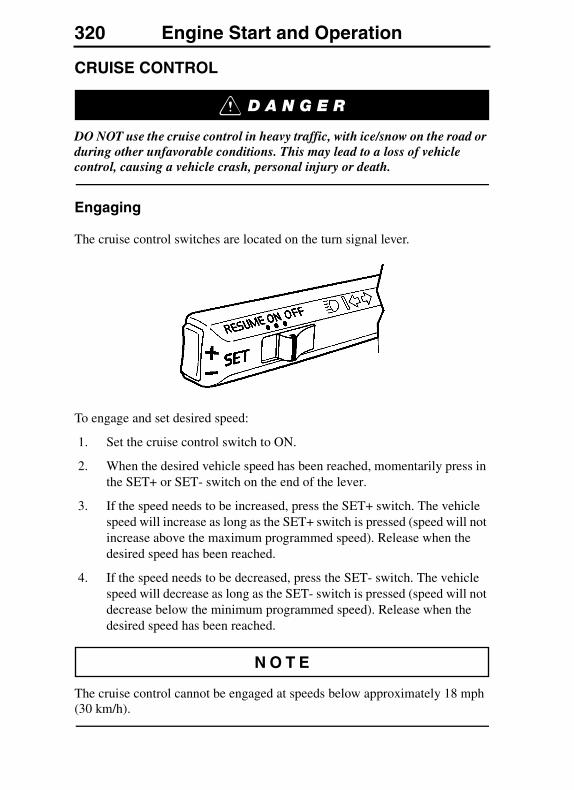
320 Engine Start and Operation
CRUISE CONTROL
DO NOT use the cruise control in heavy traffic, with ice/snow on the road or during other unfavorable conditions. This may lead to a loss of vehicle control, causing a vehicle crash, personal injury or death.
Engaging
The cruise control switches are located on the turn signal lever.
To engage and set desired speed:
1. Set the cruise control switch to ON.
2. When the desired vehicle speed has been reached, momentarily press in the SET+ or SET- switch on the end of the lever.
3. If the speed needs to be increased, press the SET+ switch. The vehicle speed will increase as long as the SET+ switch is pressed (speed will not increase above the maximum programmed speed). Release when the desired speed has been reached.
4. If the speed needs to be decreased, press the SET- switch. The vehicle speed will decrease as long as the SET- switch is pressed (speed will not decrease below the minimum programmed speed). Release when the desired speed has been reached.
The cruise control cannot be engaged at speeds below approximately 18 mph (30 km/h).
Engine Start and Operation 321
Disengaging
The cruise control is disengaged if the brake or clutch pedal is depressed, or if the cruise control switch is set to OFF. If the ignition key is turned back to the accessories position (I), the cruise control system will automatically be disengaged.
Resuming Vehicle Speed
The previously selected cruise speed is retained in the memory. When the cruise control switch is pushed to the RESUME position, the vehicle resumes the previously set speed (provided vehicle speed exceeds approximately 10 mph (15 km/h) when the switch is pressed).
Acceleration
Momentary acceleration (such as for passing another vehicle) does not interrupt cruise control operation. After passing, release accelerator and let the vehicle slow to cruise control speed. The previously set speed will then be maintained without having to set the switch to RESUME.
On vehicles equipped with Eaton VORAD SmartCruise, cruise control is disengaged in the event the SmartCruise system fails to operate. You must stop the truck, turn the ignition off and on, and activate the control twice in order for the cruise control to operate.
Read the Eaton VORAD Collision Warning System Driver Reference Manual before taking a vehicle equipped with VORAD out on the road.

322 Engine Start and Operation
FUELING
Air is always present inside the fuel tanks, entering mainly through the tank ventilation. With the air being heated and cooled, condensation is formed and water is mixed in the fuel. To avoid condensation when the vehicle is parked for longer periods, fill the tanks up to 95% of capacity. Do not fill more than that, as the fuel needs to have room for expansion during the heat of the day.
DO NOT carry extra fuel containers in the cab. Fuel containers, full or empty, may leak, explode or give added fuel to a fire. Failure to follow this precaution may lead to serious personal injury or death.
DO NOT smoke while fueling the vehicle. The glow from the cigar/cigarette can ignite the diesel fuel, causing an explosion resulting in serious personal injury or death.
Do not remove the fuel tank cap near an open flame. Diesel fuel vapors are combustible and can cause an explosion or fire, resulting in severe personal injury or death.
Clutch and Transmission 323CLUTCH AND TRANSMISSION
CLUTCH
General
Before starting the engine, set the parking brakes and place the transmission in neutral. Failure to do so can result in unexpected vehicle movement and can cause serious personal injury and death.
DO NOT allow the clutch to slip excessively. This would cause excessive heat to be generated and the clutch will be damaged and bring on premature failure. As soon as the vehicle is moving, remove the foot from the pedal for complete clutch engagement. Once the clutch is fully engaged, heat and wear does not affect it.
DO NOT shock load the drive line through rapid engagement of the clutch. Extreme care should be taken when driving heavy loads up hills. Always use the lowest gear when starting out under adverse conditions.
When operating a vehicle equipped with a clutch brake, the clutch pedal should not be depressed more than halfway to the floor while shifting, except when the vehicle is at a stop. To re-enter the low gear from neutral or reverse, or to enter reverse gear from neutral or low, the clutch should be depressed all the way to engage the clutch brake. This stops the rotation of the transmission input shaft and provides an easy, quiet gear engagement.
324 BrakesBRAKES
BRAKESBrake Safety Information
DO NOT inspect or adjust parts or components in the brake system without setting the parking brake, placing the transmission in neutral and securely chocking the wheels. If the vehicle is not secured to prevent uncontrolled vehicle movement, it could roll and cause severe personal injury or death.
DO NOT use replacement parts anywhere in the brake system unless it conforms exactly to original specifications. A nonconforming part in your vehicle's brake system could cause a malfunction, leading to loss of control of the vehicle resulting in severe personal injury or death.
DO NOT ride the brakes going down steep hills. The brakes could overheat and lose their effectiveness. Always choose a low gear before going down the grade and reduce speed to help control vehicle speed. Losing the brakes going downhill can lead to an accident causing serious personal injury or death.
DO NOT operate the vehicle when there is a malfunction in the compressed air system. An air brake system with leaks or other malfunctions may prevent the brake system from operating properly. The vehicle should not be operated until the system is repaired and all brake circuits are working properly. Failure to repair the system can lead to loss of control of the vehicle resulting in severe personal injury or death.
The brake system is a critical vehicle safety system. For your safety and for those around you, follow the recommended preventive maintenance checks. If any problems occur, have them investigated immediately by an authorized service facility. Failure to properly maintain the brake system can result in compromised brake efficiency and may lead to loss of control of the vehicle resulting in severe personal injury or death.
Brakes 325
DO NOT drive through deep water. The brake system can be affected so the braking efficiency is less or the brakes pull the vehicle to one side. This could lead to an accident, personal injury or death.
Manually adjusting an automatic slack adjuster should only be performed as a temporary measure to correct brake adjustment in an emergency situation, as it is likely the brake will soon be out of adjustment again. Manual adjustment of an automatic slack adjuster does not repair the underlying brake adjustment problem.
General
All Volvo vehicles are designed to meet or exceed all applicable federal brake standards and regulations. They use a dual circuit, compressed air system. It consists of two independent brake systems that use a single set of brake controls. Each circuit is supplied by its own compressed air tank. Both air tanks receive compressed air from the same supply tank (wet tank) and are charged with equal pressure. The two circuits are interconnected for the parking brake system.
DO NOT release the parking brake or attempt to move the vehicle until brake air pressure in both circuits is at least 100 psi (690 kPa). Failure to follow this procedure may lead to uncontrolled vehicle movement and cause severe personal injury or death.
Never release or drive a truck that has a brake discrepancy — no matter how minor — until it has been repaired or corrected. Failure to repair brake discrepancies can result in compromised brake efficiency and may lead to loss of control of the vehicle resulting in severe personal injury or death.
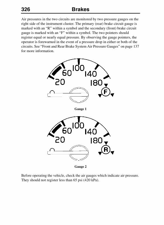
326 Brakes
Air pressures in the two circuits are monitored by two pressure gauges on the right side of the instrument cluster. The primary (rear) brake circuit gauge is marked with an “R” within a symbol and the secondary (front) brake circuit gauge is marked with an “F” within a symbol. The two pointers should register equal or nearly equal pressure. By observing the gauge pointers, the operator is forewarned in the event of a pressure drop in either or both of the circuits. See “Front and Rear Brake System Air Pressure Gauges” on page 137 for more information.
Gauge 1
Gauge 2
Before operating the vehicle, check the air gauges which indicate air pressure. They should not register less than 65 psi (420 kPa).

Brakes 327
Both circuits are piped into a dual brake valve, which simultaneously applies front and rear axle service brakes during each brake application. In the event of a failure in either one of the circuits, the other circuit becomes the emergency circuit for applying the brakes.
The Master Warning Telltale and buzzer alerts of a dangerous situation. Air pressure is low and the remaining air volume may not be enough for repeated braking. Failure to heed this warning can result in loss of braking control, vehicle accident and injury or death.
Master Warning Telltale
An important feature of the brake system is that an automatic spring brake application does not take place as a result of an air loss in only one of the two circuits. In this case, brake control remains in the foot brake valve. In each air pressure gauge, there is a warning light connected to a low pressure switch that comes on if air pressure goes below 60 psi (420 kPa). At the same time, the buzzer will sound and the main warning telltale will come on. This pressure drop warns the operator to make a manual emergency stop before an automatic emergency stop takes place.
328 Brakes
Brake System Controls
The air compressor, governor, pressure regulator valve and reservoirs are control devices. Their function is to build up, maintain and control air pressure in the reservoirs. This is so that pressure is held constant between the minimum and maximum range established for air brake operation.
The brake valve, quick release valve, brake chambers and slack adjusters are application devices. They distribute the air pressure and convert its energy into the mechanical force necessary to apply or release the brakes.
Foot Brake Valve
The foot brake valve is directly connected to the brake pedal. The valve gives a progressive output against the pedal travel. This allows better control of the pressure in the first half of the pedal travel. In the last half of the pedal travel, the pressure output increase is faster.
The foot brake valve applies the service brakes, incorporating both the primary and secondary air systems. The primary system controls the rear brakes and the secondary system controls the front brakes. The foot brake valve receives air from the compressed air tanks. Air pressure is then delivered to the wheel brake chambers as required by the amount of pressure exerted on the foot brake pedal. The brake chamber force then applies the wheel brakes.
From the operator's viewpoint, operating the foot brake valve of a vehicle equipped with air brakes differs very little from the operation of a conventionally braked vehicle. Because the operation of the brake pedal requires scarcely more effort than depressing the average throttle pedal, air brakes are naturally much easier to control. If the driver gives full attention to the following suggestions, a little experience will make him/her thoroughly familiar with the air-controlled braking of this vehicle.
Failure to observe these precautions can result in loss of vehicle control and serious personal injury or death.
1. The best possible stop will be made when the first brake application is as firm as the speed and road condition permit. Then, ease off as the speed is reduced. Never apply the brakes lightly at first and increase the pressure as the speed diminishes.
2. DO NOT fan the brake pedal. Fanning gives poor brake performance and wastes air.

Brakes 329
3. The air brake is designed so that when the brake pedal is fully depressed, an emergency application results. This application should be made only in an emergency situation.
4. In making a stop or a slow-down, allow the transmission to remain in gear with the throttle closed, disengaging the clutch only when engine idling speed is reached.
5. When parking the vehicle, place the transmission in neutral and set the parking brake before shutting down the engine.
6. When descending a long grade, do not use the service brakes too long or too often. The brakes may overheat and lose their effectiveness.
7. Before descending a steep grade, the transmission should be shifted into a lower gear and the vehicle speed reduced. Other speed retarding devices should also be used if available (engine brakes, retarders or trailer hand control valves).
Parking Brake/Trailer Supply Valves
Trucks/Tractors may have two air control valves on the instrument panel:
� Trailer Supply (red octagonal knob)
� System Park (yellow diamond knob)
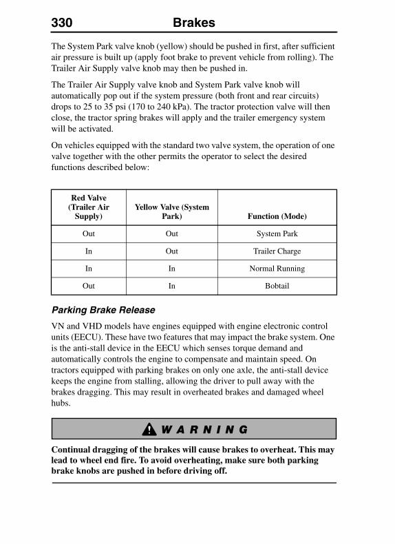
330 Brakes
The System Park valve knob (yellow) should be pushed in first, after sufficient air pressure is built up (apply foot brake to prevent vehicle from rolling). The Trailer Air Supply valve knob may then be pushed in.
The Trailer Air Supply valve knob and System Park valve knob will automatically pop out if the system pressure (both front and rear circuits) drops to 25 to 35 psi (170 to 240 kPa). The tractor protection valve will then close, the tractor spring brakes will apply and the trailer emergency system will be activated.
On vehicles equipped with the standard two valve system, the operation of one valve together with the other permits the operator to select the desired functions described below:
Parking Brake Release
VN and VHD models have engines equipped with engine electronic control units (EECU). These have two features that may impact the brake system. One is the anti-stall device in the EECU which senses torque demand and automatically controls the engine to compensate and maintain speed. On tractors equipped with parking brakes on only one axle, the anti-stall device keeps the engine from stalling, allowing the driver to pull away with the brakes dragging. This may result in overheated brakes and damaged wheel hubs.
Continual dragging of the brakes will cause brakes to overheat. This may lead to wheel end fire. To avoid overheating, make sure both parking brake knobs are pushed in before driving off.
Red Valve (Trailer Air
Supply)Yellow Valve (System
Park) Function (Mode)
Out Out System Park
In Out Trailer Charge
In In Normal Running
Out In Bobtail

Brakes 331
If the yellow knob is pulled out and the red knob is pushed in, a condition is created where the trailer parking brakes are not applied and only the single drive axle brakes are applied. In this condition, the vehicle can be driven away. Therefore, it is very important that the driver make sure the yellow AND red knobs are pushed in all the way before driving the vehicle.
Correct Driving Position: Both knobs fully in
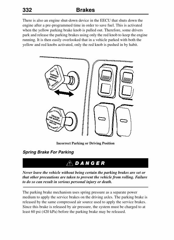
332 Brakes
There is also an engine shut-down device in the EECU that shuts down the engine after a pre-programmed time in order to save fuel. This is activated when the yellow parking brake knob is pulled out. Therefore, some drivers park and release the parking brakes using only the red knob to keep the engine running. It is then easily overlooked that in a vehicle parked with both the yellow and red knobs activated, only the red knob is pushed in by habit.
Incorrect Parking or Driving Position
Spring Brake For Parking
Never leave the vehicle without being certain the parking brakes are set or that other precautions are taken to prevent the vehicle from rolling. Failure to do so can result in serious personal injury or death.
The parking brake mechanism uses spring pressure as a separate power medium to apply the service brakes on the driving axles. The parking brake is released by the same compressed air source used to apply the service brakes. Since this brake is released by air pressure, the system must be charged to at least 60 psi (420 kPa) before the parking brake may be released.
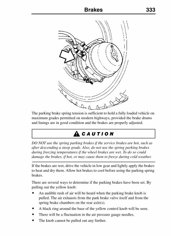
Brakes 333
The parking brake spring tension is sufficient to hold a fully loaded vehicle on maximum grades permitted on modern highways, provided the brake drums and linings are in good condition and the brakes are properly adjusted.
DO NOT use the spring parking brakes if the service brakes are hot, such as after descending a steep grade. Also, do not use the spring parking brakes during freezing temperatures if the wheel brakes are wet. To do so could damage the brakes, if hot, or may cause them to freeze during cold weather.
If the brakes are wet, drive the vehicle in low gear and lightly apply the brakes to heat and dry them. Allow hot brakes to cool before using the parking spring brakes.
There are several ways to determine if the parking brakes have been set. By pulling out the yellow knob:
� An audible rush of air will be heard when the parking brake knob is pulled. The air exhausts from the park brake valve itself and from the spring brake chambers on the rear axle(s).
� A black ring around the base of the yellow control knob will be seen.
� There will be a fluctuation in the air pressure gauge needles.
� The knob cannot be pulled out any further.
334 Brakes
DO NOT attempt in any way to disassemble or tamper with the spring brake chamber. The force stored in the spring, if suddenly released, can cause serious personal injury or death.
DO NOT apply the parking brake while the vehicle is moving. The rear wheels may lock up causing loss of vehicle control leading to an accident, personal injury or death.
Trailer Brake Hand Control
The trailer hand brake control is not a parking brake valve and must not be used as one. This brake is not designed to hold the vehicle stationary. Failure to follow these instructions can result in the unintentional movement of the vehicle and may cause personal injury or death.
DO NOT use the trailer brake hand control as a parking brake. The brakes could release and the vehicle could roll, causing a vehicle accident, personal injury or death.
The hand control valve for the trailer brakes engages the trailer brakes independently from the vehicle brakes. The valve can be fully or partially engaged but in any partial position it will be overridden by a full application of the foot brake valve.
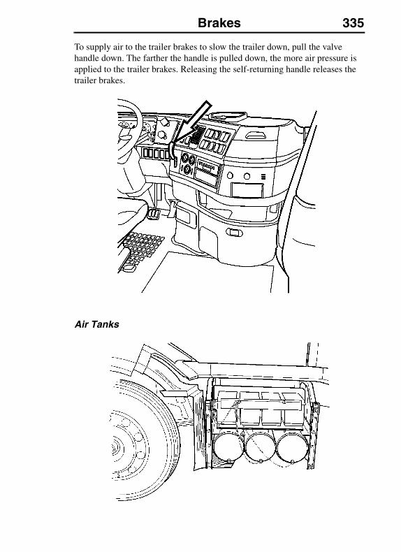
Brakes 335
To supply air to the trailer brakes to slow the trailer down, pull the valve handle down. The farther the handle is pulled down, the more air pressure is applied to the trailer brakes. Releasing the self-returning handle releases the trailer brakes.
Air Tanks
336 Brakes
When draining the air tanks, do not look into the area of the draining air. Dirt or sludge particles may be in the air stream and could cause eye injury.
All air tanks on the vehicle should be drained daily. Empty any moisture from air tanks by pulling the drain valve wire or by opening the drain cocks and allowing the air pressure to drain completely. Make sure the drain cocks close properly after draining. During draining the tanks should be checked for condensation fluid even if an automatic drain valve is installed.
Trucks with Wabco air dryers: Periodically drain the purge tank to check for contamination, water, oil etc.
Trucks with automated Meritor Transmission: Drain the transmission air supply tank located on the right hand rail daily to check for contamination, water, oil etc.
The “121” Brake Standard
This manual refers occasionally to “121” brakes. Although some operators believe “121” only applies to vehicles equipped with anti-lock devices, the “121” standard applies to all vehicles that are capable of on-highway operation.
The “121” is a Federal requirement also covering alterations or changes to parts or systems related to the “121” standard once the vehicle has been placed in service. The owner and operator should be aware that it is a violation for any repair facility to make any part or component inoperative when it is required for “121” compliance.
Brakes 337
Charging Air To Another Vehicle
There are many methods which may be used to charge the air system of another vehicle. Vehicles equipped with the standard two-valve system (trailer supply and parking brake) must use the following procedure when using the emergency trailer air line as an auxiliary air source, other than to charge the trailer air reservoirs.
Before working on a vehicle, set the parking brakes, place the transmission in neutral, and block the wheels. Failure to do so can result in unexpected vehicle movement and can cause serious personal injury or death.
1. Connect the emergency trailer air line to the auxiliary source.
2. Start the engine.
ANTILOCK BRAKING SYSTEM (ABS)
The vehicle has a standard brake system, equipped with an electronic speed monitoring and control system, Antilock Braking System (ABS). ABS monitors wheel speed continuously but is not involved in controlling the wheel speed unless there is an emergency. In normal braking applications, the standard air brake system is in effect.
For proper ABS operation, DO NOT change tire sizes. The size of the tires installed during production are programmed into the electronic control unit. Installing different sized tires could result in a reduced brake force, leading to longer stopping distances or accidents.
There is a sensor installed in each wheel on a monitored axle. The sensors transmit information to the electronic control unit (ECU). The ECU interprets the signals and calculates wheel speed, wheel retarding and a vehicle reference speed. If the calculations indicate a wheel lock-up situation, a signal is sent from the ECU to the appropriate ABS modulator valve to reduce braking pressure. During emergency braking, the modulator valve alternately reduces, increases or maintains air pressure in the brake chamber to prevent wheel lock-up.
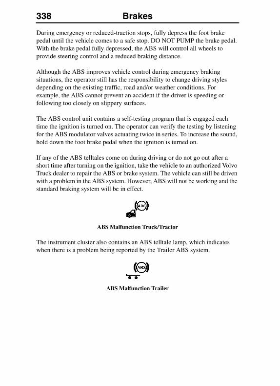
338 Brakes
During emergency or reduced-traction stops, fully depress the foot brake pedal until the vehicle comes to a safe stop. DO NOT PUMP the brake pedal. With the brake pedal fully depressed, the ABS will control all wheels to provide steering control and a reduced braking distance.
Although the ABS improves vehicle control during emergency braking situations, the operator still has the responsibility to change driving styles depending on the existing traffic, road and/or weather conditions. For example, the ABS cannot prevent an accident if the driver is speeding or following too closely on slippery surfaces.
The ABS control unit contains a self-testing program that is engaged each time the ignition is turned on. The operator can verify the testing by listening for the ABS modulator valves actuating twice in series. To increase the sound, hold down the foot brake pedal when the ignition is turned on.
If any of the ABS telltales come on during driving or do not go out after a short time after turning on the ignition, take the vehicle to an authorized Volvo Truck dealer to repair the ABS or brake system. The vehicle can still be driven with a problem in the ABS system. However, ABS will not be working and the standard braking system will be in effect.
ABS Malfunction Truck/Tractor
The instrument cluster also contains an ABS telltale lamp, which indicates when there is a problem being reported by the Trailer ABS system.
ABS Malfunction Trailer
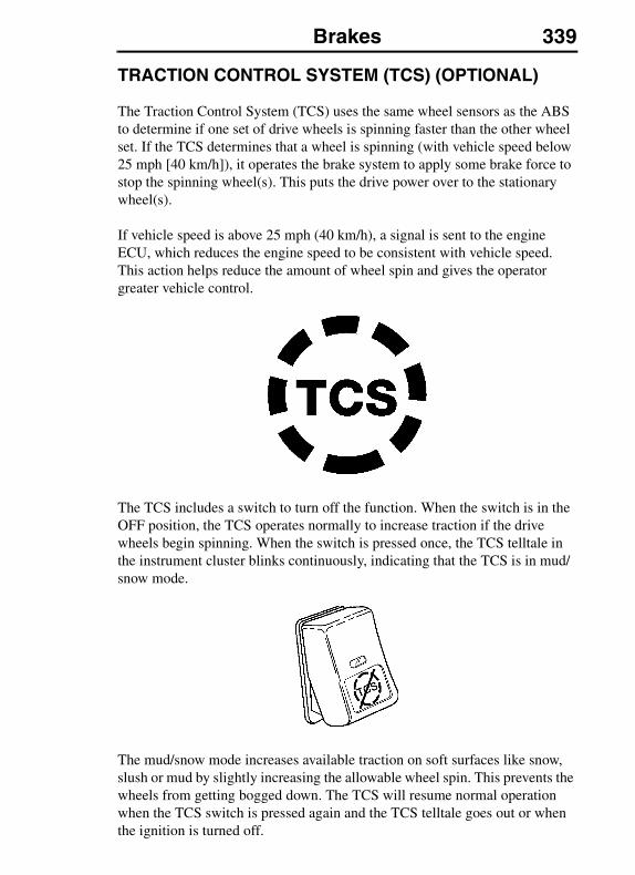
Brakes 339
TRACTION CONTROL SYSTEM (TCS) (OPTIONAL)
The Traction Control System (TCS) uses the same wheel sensors as the ABS to determine if one set of drive wheels is spinning faster than the other wheel set. If the TCS determines that a wheel is spinning (with vehicle speed below 25 mph [40 km/h]), it operates the brake system to apply some brake force to stop the spinning wheel(s). This puts the drive power over to the stationary wheel(s).
If vehicle speed is above 25 mph (40 km/h), a signal is sent to the engine ECU, which reduces the engine speed to be consistent with vehicle speed. This action helps reduce the amount of wheel spin and gives the operator greater vehicle control.
The TCS includes a switch to turn off the function. When the switch is in the OFF position, the TCS operates normally to increase traction if the drive wheels begin spinning. When the switch is pressed once, the TCS telltale in the instrument cluster blinks continuously, indicating that the TCS is in mud/snow mode.
The mud/snow mode increases available traction on soft surfaces like snow, slush or mud by slightly increasing the allowable wheel spin. This prevents the wheels from getting bogged down. The TCS will resume normal operation when the TCS switch is pressed again and the TCS telltale goes out or when the ignition is turned off.
340 Brakes
DO NOT engage the differential locks while wheels are spinning. Serious damage to the differential will occur. See “Differential Locks” on page 374 for more information.
VEHICLE SPEED RETARDING DEVICES
When operating a tractor bobtail (without a trailer) or on slippery roads, the engine brake switch must be in the “OFF” position. Failure to follow this instruction can result in loss of vehicle control and serious personal injury or death.
The vehicle ABS will automatically turn off the vehicle speed retarding device, IF one of the sensed rear wheels is locking up as a result of vehicle speed retarding device operation. The vehicle speed retarding device will be turned back on automatically when the wheels become unlocked. Consider switching to a lower braking level if this occurs frequently.
A vehicle speed retarding device (such as a “Intebrake,” “C-Brake,” “Exhaust Brake,” etc.) is not intended to bring the vehicle to a stop. A vehicle speed retarding device is only intended to retard the vehicle speed under certain conditions.
If a Volvo engine is equipped with a Volvo Engine Brake, the brake will not operate with full power until the engine coolant temperature has reached 110°F (45°C).
It is normal for there to be a slight delay in the application of a vehicle speed retarding device. When using devices of this type, be sure to think ahead and analyze conditions in order to use the device properly.
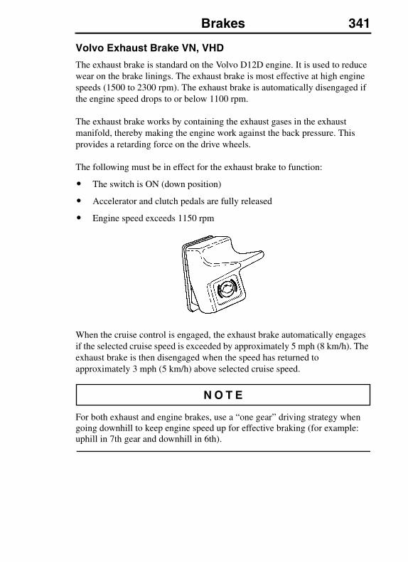
Brakes 341
Volvo Exhaust Brake VN, VHD
The exhaust brake is standard on the Volvo D12D engine. It is used to reduce wear on the brake linings. The exhaust brake is most effective at high engine speeds (1500 to 2300 rpm). The exhaust brake is automatically disengaged if the engine speed drops to or below 1100 rpm.
The exhaust brake works by containing the exhaust gases in the exhaust manifold, thereby making the engine work against the back pressure. This provides a retarding force on the drive wheels.
The following must be in effect for the exhaust brake to function:
� The switch is ON (down position)
� Accelerator and clutch pedals are fully released
� Engine speed exceeds 1150 rpm
When the cruise control is engaged, the exhaust brake automatically engages if the selected cruise speed is exceeded by approximately 5 mph (8 km/h). The exhaust brake is then disengaged when the speed has returned to approximately 3 mph (5 km/h) above selected cruise speed.
For both exhaust and engine brakes, use a “one gear” driving strategy when going downhill to keep engine speed up for effective braking (for example: uphill in 7th gear and downhill in 6th).
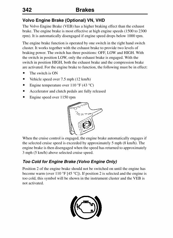
342 Brakes
Volvo Engine Brake (Optional) VN, VHDThe Volvo Engine Brake (VEB) has a higher braking effect than the exhaust brake. The engine brake is most effective at high engine speeds (1500 to 2300 rpm). It is automatically disengaged if engine speed drops below 1000 rpm.
The engine brake function is operated by one switch in the right hand switch cluster. It works together with the exhaust brake to provide two levels of braking power. The switch has three positions: OFF, LOW and HIGH. With the switch in position LOW, only the exhaust brake is engaged. With the switch in position HIGH, both the exhaust brake and the compression brake are activated. For the engine brake to function, the following must be in effect:
� The switch is ON
� Vehicle speed over 7.5 mph (12 km/h)
� Engine temperature over 110 °F (43 °C)
� Accelerator and clutch pedals are fully released
� Engine speed over 1150 rpm
When the cruise control is engaged, the engine brake automatically engages if the selected cruise speed is exceeded by approximately 5 mph (8 km/h). The engine brake is then disengaged when the speed has returned to approximately 3 mph (5 km/h) above selected cruise speed.
Too Cold for Engine Brake (Volvo Engine Only)
Position 2 of the engine brake should not be switched on until the engine has become warm (over 110 °F [45 °C]). If position 2 is selected and the engine is too cold, this symbol will be shown in the instrument cluster and the VEB is not activated.
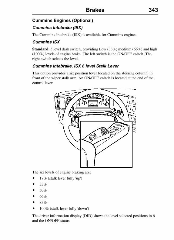
Brakes 343
Cummins Engines (Optional)
Cummins Intebrake (ISX)
The Cummins Intebrake (ISX) is available for Cummins engines.
Cummins ISX
Standard: 3 level dash switch, providing Low (33%) medium (66%) and high (100%) levels of engine brake. The left switch is the ON/OFF switch. The right switch selects the level.
Cummins Intebrake, ISX 6 level Stalk Lever
This option provides a six position lever located on the steering column, in front of the wiper stalk arm. An ON/OFF switch is located at the end of the control lever.
The six levels of engine braking are:
� 17% (stalk lever fully 'up')
� 33%
� 50%
� 66%
� 83%
� 100% (stalk lever fully 'down')
The driver information display (DID) shows the level selected positions in 6 and the ON/OFF status.
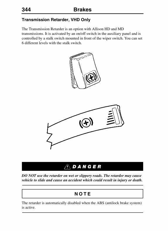
344 Brakes
Transmission Retarder, VHD Only
The Transmission Retarder is an option with Allison HD and MD transmissions. It is activated by an on/off switch in the auxiliary panel and is controlled by a stalk switch mounted in front of the wiper switch. You can set 6 different levels with the stalk switch.
DO NOT use the retarder on wet or slippery roads. The retarder may cause vehicle to slide and cause an accident which could result in injury or death.
The retarder is automatically disabled when the ABS (antilock brake system) is active.
Brakes 345
Vehicle brake lights are always on when transmission retarder is active.
Apply the retarder only when engine is at closed throttle.
Observe transmission and engine temperatures. Select the lowest possible transmission range in order to maximize the cooling system capacity and retarding. If overheating occurs, decrease the use of the retarder and use service brakes instead. Check the retarder overtemp light.
For complete warnings and instructions, refer to your Allison Transmission manual.
346 Electrical SystemELECTRICAL SYSTEM
ELECTRICAL SYSTEM
General Safety Guidelines
Failure to repair a malfunction in the electrical system can result in serious damage due to vehicle fire. Always let an experienced electrical technician perform repairs. Always determine the source of the fault; do not just treat the symptoms.
Always wear eye protection when working around batteries to prevent the risk of injury due to contact with sulfuric acid or an explosion.
Before replacing a damaged fuse, turn off all functions for that circuit. Damage to the circuit can happen. Always replace fuses and circuit breakers with the same current/amperage rating. Never substitute a fuse with foil, wire or nails. Increasing fuse or circuit breaker ratings or substituting a fuse with foil, wire or nails may result in electrical circuit overheating and possibly fire.
Over-charging a poorly charged battery can cause an explosion, which can lead to serious personal injury.
Attempting to work on electronic components without proper equipment can damage internal parts with static electricity.
Electrical System 347
Today's vehicles contain a high number of electronic devices. It is very important to exercise caution when working on a modern electrical system, charging batteries or jump starting the engine. To minimize the risk of any damage to the electronic components, follow the procedures below when work is being done to the electrical system.
Welding on the vehicle can damage the electrical system or components due to the high voltage and current spikes that normally occur when welding. It is preferable to avoid welding on an assembled vehicle. However, if any structure on or in contact with the vehicle must be welded, follow the recommendations below.
If there are other ground cables connected to the battery (such as engine ECU, transmission ECU, etc.), disconnect those wires first, then remove the main battery ground cable. Electronic modules may be damaged when their ground(s) are connected/disconnected with the main battery ground disconnected. Therefore, disconnect the main battery ground last.
DO NOT weld on the engine or engine components. Welding on the engine or components mounted on the engine can cause serious damage to the engine ECU.
DO NOT work on the electric system without proper tools and training. Repair work to the electrical system must be done by trained professionals. Your authorized Volvo Truck dealer has the right tools and trained technicians.
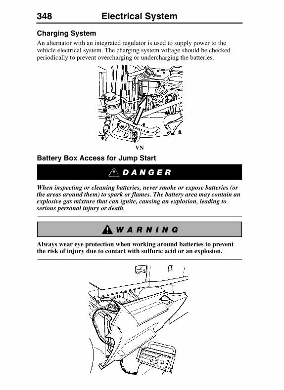
348 Electrical System
Charging SystemAn alternator with an integrated regulator is used to supply power to the vehicle electrical system. The charging system voltage should be checked periodically to prevent overcharging or undercharging the batteries.
VN
Battery Box Access for Jump Start
When inspecting or cleaning batteries, never smoke or expose batteries (or the areas around them) to spark or flames. The battery area may contain an explosive gas mixture that can ignite, causing an explosion, leading to serious personal injury or death.
Always wear eye protection when working around batteries to prevent the risk of injury due to contact with sulfuric acid or an explosion.
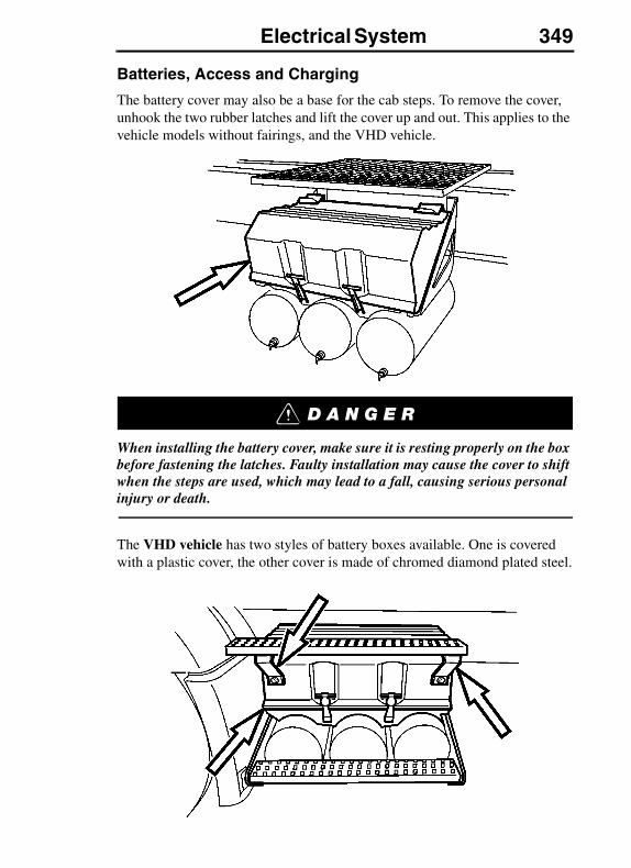
Electrical System 349
Batteries, Access and Charging
The battery cover may also be a base for the cab steps. To remove the cover, unhook the two rubber latches and lift the cover up and out. This applies to the vehicle models without fairings, and the VHD vehicle.
When installing the battery cover, make sure it is resting properly on the box before fastening the latches. Faulty installation may cause the cover to shift when the steps are used, which may lead to a fall, causing serious personal injury or death.
The VHD vehicle has two styles of battery boxes available. One is covered with a plastic cover, the other cover is made of chromed diamond plated steel.

350 Electrical System
Battery posts, terminals and related accessories contain lead compounds, chemicals known to the state of California to cause cancer and reproductive harm. Wash hands after handling.
There may be up to four batteries installed. Always make sure the batteries are fastened properly in the box.
When disconnecting battery terminals, always disconnect the engine ECU fuse(s) first, then the ECU ground wire(s), then the main ground cable, and finally the main positive cable.
Reverse this order when reconnecting the cables and wires.
Battery Jump Starting and Charging
To access the batteries on a vehicle equipped with side fairings, open the fold-out fairing. On the second battery from the front there are special, larger brass posts installed to accept jumper cables.
When jumping batteries to start an engine, it is important that the jumper cables are connected directly from one set of batteries in one vehicle to the other set of batteries in the other vehicle (unless vehicle is equipped with optional Emergency Start System). This way the cranking current is carried through the proper starter wiring.
Make sure the cables are routed under the fairing, then connected as shown in illustration. Close and lock the fairing before climbing into the cab.
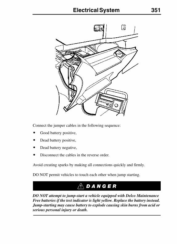
Electrical System 351
Connect the jumper cables in the following sequence:
� Good battery positive,
� Dead battery positive,
� Dead battery negative,
� Disconnect the cables in the reverse order.
Avoid creating sparks by making all connections quickly and firmly.
DO NOT permit vehicles to touch each other when jump starting.
DO NOT attempt to jump-start a vehicle equipped with Delco Maintenance Free batteries if the test indicator is light yellow. Replace the battery instead. Jump-starting may cause battery to explode causing skin burns from acid or serious personal injury or death.
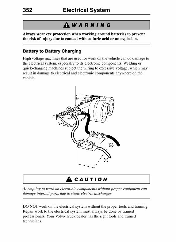
352 Electrical System
Always wear eye protection when working around batteries to prevent the risk of injury due to contact with sulfuric acid or an explosion.
Battery to Battery Charging
High voltage machines that are used for work on the vehicle can do damage to the electrical system, especially to its electronic components. Welding or quick-charging machines subject the wiring to excessive voltage, which may result in damage to electrical and electronic components anywhere on the vehicle.
Attempting to work on electronic components without proper equipment can damage internal parts due to static electric discharges.
DO NOT work on the electrical system without the proper tools and training. Repair work to the electrical system must always be done by trained professionals. Your Volvo Truck dealer has the right tools and trained technicians.
Electrical System 353
Battery, Low State of Charge
If the batteries are discharged to the point where they do not have enough stored energy to start the engine, they should be recharged using a low charge current, not to exceed 14.5 to 15.0 volts.
If the vehicle needs to be started immediately, use a starting batteries charger.
If the voltage power is exceeded this can cause damage to the lighting system and bolts.
DO NOT use battery chargers with very high “boosting” capability. These produce a high voltage that may cause damage to the vehicle electrical and electronic components.
Welding
Before welding on the vehicle, electrical power needs to be disconnected and some components must also be disconnected:
Welding on the vehicle can damage the electrical system or components due to the high voltage and current spikes that normally occur when welding. It is preferable to avoid welding on an assembled vehicle. However, if any structure on or in contact with the vehicle must be welded, follow the recommendations below.
If there are other ground cables connected to the battery (such as engine ECU, transmission ECU, etc.), disconnect those wires in the sequence shown, then remove the main battery ground cable. Electronic modules may be damaged when their ground(s) are connected/disconnected with the main battery ground disconnected. Therefore, disconnect the main battery ground last.
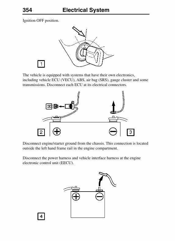
354 Electrical System
Ignition OFF position.
The vehicle is equipped with systems that have their own electronics, including vehicle ECU (VECU), ABS, air bag (SRS), gauge cluster and some transmissions. Disconnect each ECU at its electrical connectors.
Disconnect engine/starter ground from the chassis. This connection is located outside the left hand frame rail in the engine compartment.
Disconnect the power harness and vehicle interface harness at the engine electronic control unit (EECU).
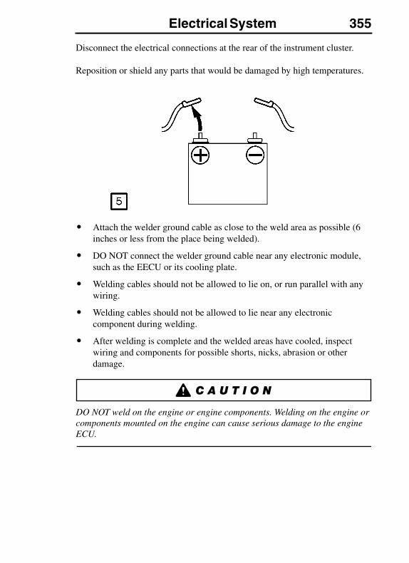
Electrical System 355
Disconnect the electrical connections at the rear of the instrument cluster.
Reposition or shield any parts that would be damaged by high temperatures.
� Attach the welder ground cable as close to the weld area as possible (6 inches or less from the place being welded).
� DO NOT connect the welder ground cable near any electronic module, such as the EECU or its cooling plate.
� Welding cables should not be allowed to lie on, or run parallel with any wiring.
� Welding cables should not be allowed to lie near any electronic component during welding.
� After welding is complete and the welded areas have cooled, inspect wiring and components for possible shorts, nicks, abrasion or other damage.
DO NOT weld on the engine or engine components. Welding on the engine or components mounted on the engine can cause serious damage to the engine ECU.
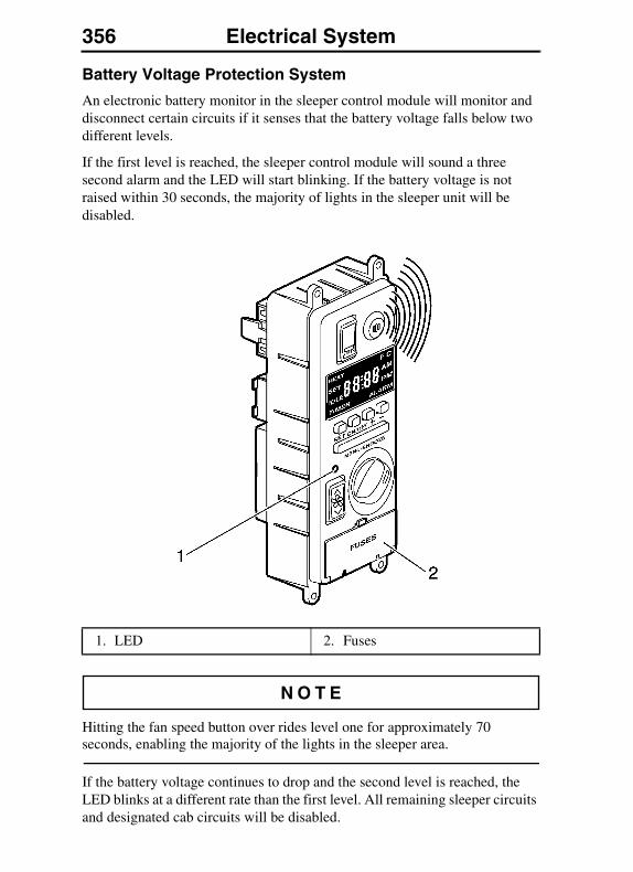
356 Electrical System
Battery Voltage Protection System
An electronic battery monitor in the sleeper control module will monitor and disconnect certain circuits if it senses that the battery voltage falls below two different levels.
If the first level is reached, the sleeper control module will sound a three second alarm and the LED will start blinking. If the battery voltage is not raised within 30 seconds, the majority of lights in the sleeper unit will be disabled.
Hitting the fan speed button over rides level one for approximately 70 seconds, enabling the majority of the lights in the sleeper area.
If the battery voltage continues to drop and the second level is reached, the LED blinks at a different rate than the first level. All remaining sleeper circuits and designated cab circuits will be disabled.
1. LED 2. Fuses
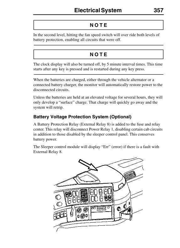
Electrical System 357
In the second level, hitting the fan speed switch will over ride both levels of battery protection, enabling all circuits that were off.
The clock display will also be turned off, by 5 minute interval times. This time starts after any key is pressed and is restarted during any key press.
When the batteries are charged, either through the vehicle alternator or a connected battery charger, the monitor will automatically restore power to the disconnected circuits.
Unless the batteries are held at an elevated voltage for several hours, they will only develop a “surface” charge. That charge will quickly go away and the system will retrip.
Battery Voltage Protection System (Optional)
A Battery Protection Relay (External Relay 8) is added to the fuse and relay center. This relay will disconnect Power Relay 1, disabling certain cab circuits in addition to those disabled by the sleeper control panel. This conserves battery power.
The Sleeper control module will display “Err” (error) if there is a fault with External Relay 8.
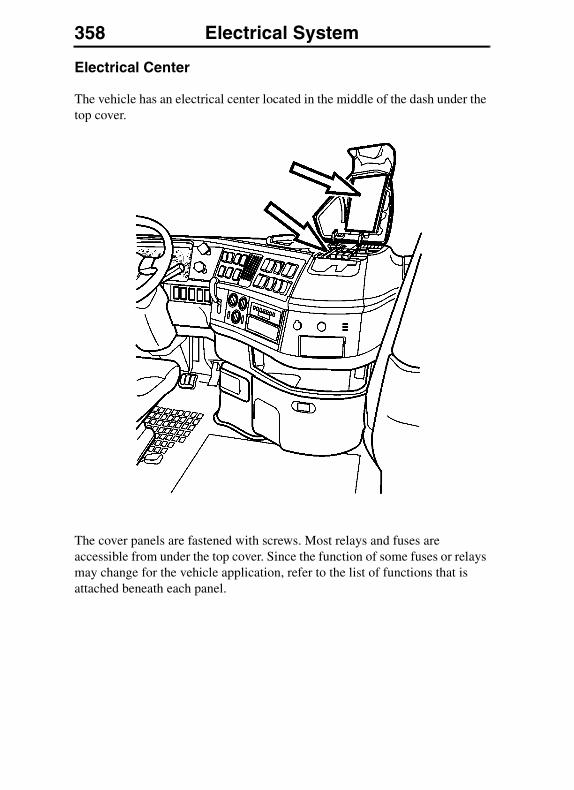
358 Electrical System
Electrical Center
The vehicle has an electrical center located in the middle of the dash under the top cover.
The cover panels are fastened with screws. Most relays and fuses are accessible from under the top cover. Since the function of some fuses or relays may change for the vehicle application, refer to the list of functions that is attached beneath each panel.

Electrical System 359
VN Fuse and Relay Center
VHD Fuse and Relay Center
Additional relays are located in the left hand luggage compartment, attached to the sleeper harness.
These relays have limited optional sleeper functions.
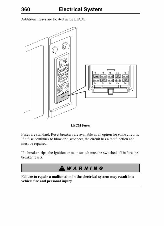
360 Electrical System
Additional fuses are located in the LECM.
LECM Fuses
Fuses are standard. Reset breakers are available as an option for some circuits. If a fuse continues to blow or disconnect, the circuit has a malfunction and must be repaired.
If a breaker trips, the ignition or main switch must be switched off before the breaker resets.
Failure to repair a malfunction in the electrical system may result in a vehicle fire and personal injury.
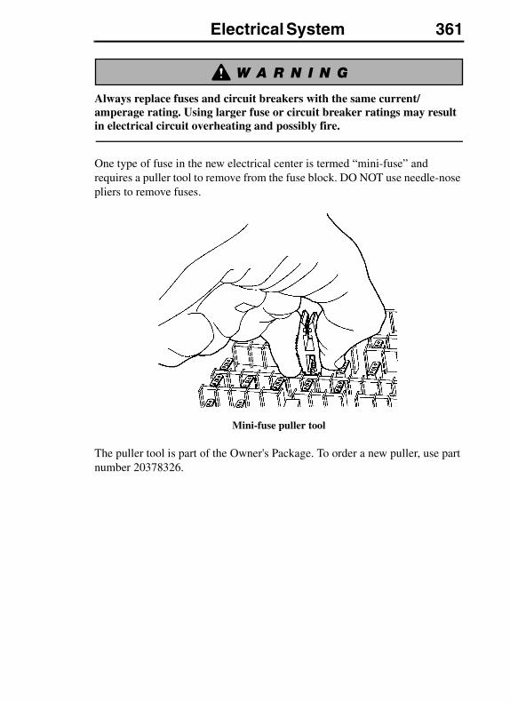
Electrical System 361
Always replace fuses and circuit breakers with the same current/amperage rating. Using larger fuse or circuit breaker ratings may result in electrical circuit overheating and possibly fire.
One type of fuse in the new electrical center is termed “mini-fuse” and requires a puller tool to remove from the fuse block. DO NOT use needle-nose pliers to remove fuses.
Mini-fuse puller tool
The puller tool is part of the Owner's Package. To order a new puller, use part number 20378326.
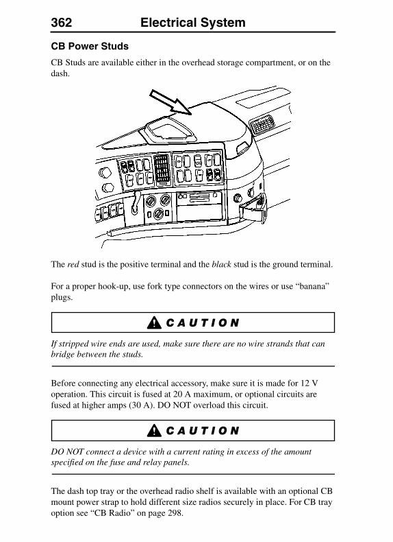
362 Electrical System
CB Power Studs
CB Studs are available either in the overhead storage compartment, or on the dash.
The red stud is the positive terminal and the black stud is the ground terminal.
For a proper hook-up, use fork type connectors on the wires or use “banana” plugs.
If stripped wire ends are used, make sure there are no wire strands that can bridge between the studs.
Before connecting any electrical accessory, make sure it is made for 12 V operation. This circuit is fused at 20 A maximum, or optional circuits are fused at higher amps (30 A). DO NOT overload this circuit.
DO NOT connect a device with a current rating in excess of the amount specified on the fuse and relay panels.
The dash top tray or the overhead radio shelf is available with an optional CB mount power strap to hold different size radios securely in place. For CB tray option see “CB Radio” on page 298.
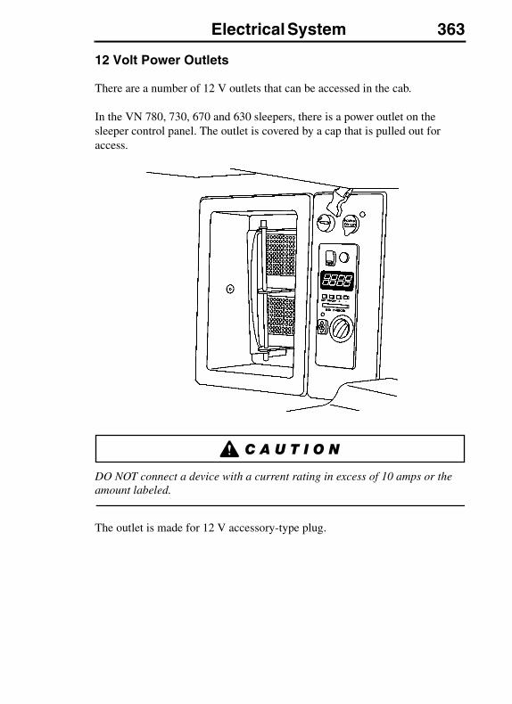
Electrical System 363
12 Volt Power Outlets
There are a number of 12 V outlets that can be accessed in the cab.
In the VN 780, 730, 670 and 630 sleepers, there is a power outlet on the sleeper control panel. The outlet is covered by a cap that is pulled out for access.
DO NOT connect a device with a current rating in excess of 10 amps or the amount labeled.
The outlet is made for 12 V accessory-type plug.

364 Electrical System
12 Volt LocationsThere is an optional power outlet in the driver and passenger side cabinets. Accessories for this cabinet will have ON/OFF switches of their own.
The cabinet 12 V outlets are made for 12 V accessory-type plugs.
VN 780
VN 670, VN 630
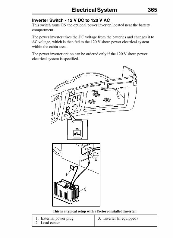
Electrical System 365
Inverter Switch - 12 V DC to 120 V ACThis switch turns ON the optional power inverter, located near the battery compartment.
The power inverter takes the DC voltage from the batteries and changes it to AC voltage, which is then fed to the 120 V shore power electrical system within the cabin area.
The power inverter option can be ordered only if the 120 V shore power electrical system is specified.
This is a typical setup with a factory-installed Inverter.
1. External power plug2. Load center
3. Inverter (if equipped)
366 Electrical System
A tripped circuit is usually an indication of a fault in the circuit, or of an appliance being supplied with power. Every effort should be made to identify and correct any fault that exists.
When parked on wet ground, avoid using an external power source to connect the cab power plug. Water is a conductor of electricity, in wet conditions electrical shock can occur which can result in personal injury or death.
120 Volt System and Outlets
The VN 780, 670 and 630 are available with an optional 120 V AC service, used for longer parking while still living in the vehicle. The 120 V AC service is supplied from outside sources.
When parked on wet ground, avoid using an external power source to connect the cab power plug. Water is a conductor of electricity, in wet conditions electrical shock can occur which can result in personal injury or death.
To hook up the service, there is a socket located behind the driver side door.
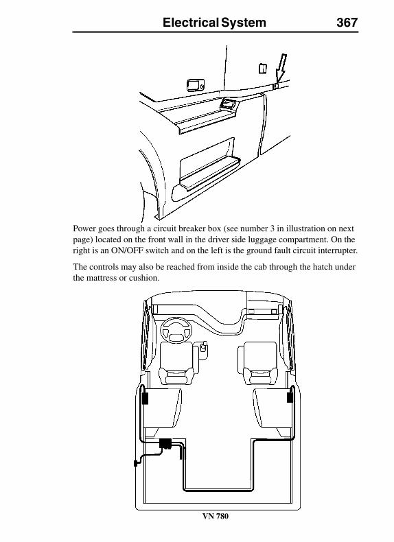
Electrical System 367
Power goes through a circuit breaker box (see number 3 in illustration on next page) located on the front wall in the driver side luggage compartment. On the right is an ON/OFF switch and on the left is the ground fault circuit interrupter.
The controls may also be reached from inside the cab through the hatch under the mattress or cushion.
VN 780
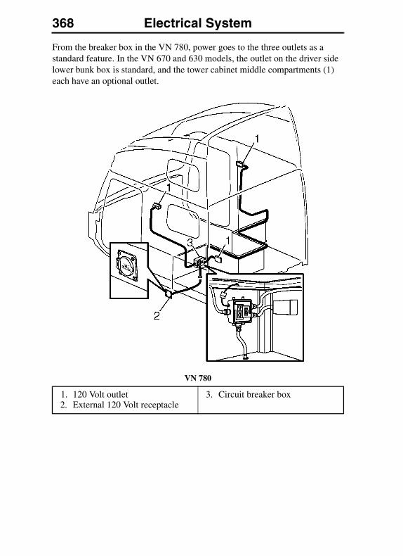
368 Electrical System
From the breaker box in the VN 780, power goes to the three outlets as a standard feature. In the VN 670 and 630 models, the outlet on the driver side lower bunk box is standard, and the tower cabinet middle compartments (1) each have an optional outlet.
VN 780
1. 120 Volt outlet2. External 120 Volt receptacle
3. Circuit breaker box

Electrical System 369
VN 670, VN 630
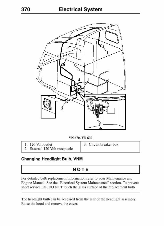
370 Electrical System
VN 670, VN 630
Changing Headlight Bulb, VNM
For detailed bulb replacement information refer to your Maintenance and Engine Manual. See the “Electrical System Maintenance” section. To prevent short service life, DO NOT touch the glass surface of the replacement bulb.
The headlight bulb can be accessed from the rear of the headlight assembly. Raise the hood and remove the cover.
1. 120 Volt outlet2. External 120 Volt receptacle
3. Circuit breaker box
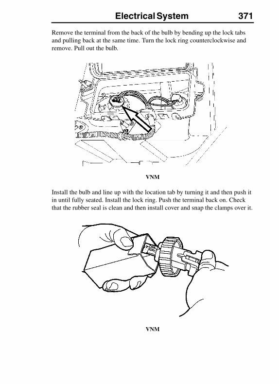
Electrical System 371
Remove the terminal from the back of the bulb by bending up the lock tabs and pulling back at the same time. Turn the lock ring counterclockwise and remove. Pull out the bulb.
VNM
Install the bulb and line up with the location tab by turning it and then push it in until fully seated. Install the lock ring. Push the terminal back on. Check that the rubber seal is clean and then install cover and snap the clamps over it.
VNM

372 Electrical System
Changing Headlight Bulb, VNL
For detailed bulb replacement information refer to your Maintenance and Engine Manual. See the “Electrical System Maintenance” section. To prevent short service life, DO NOT touch the glass surface of the replacement bulb.
The headlight bulb can be accessed from the rear of the headlight assembly. Raise the hood. In early production vehicles, remove the bulb cover by turning clockwise.
In later production vehicles, the cover can be removed in the normal counterclockwise direction.
In some cases, the cover seal may stick to the housing, which makes removal difficult. Use special tool 85104355 to assist in removal. Contact your authorized Volvo dealer for the tool.
With the cover removed, grasp the bulb assembly and turn counterclockwise to remove. Disengage the wiring connector and remove the bulb from the vehicle.
Engage the wiring harness connector to the replacement bulb assembly. Install into the headlamp housing. Check the bulb cover seal and install the bulb cover. Lower the hood and check for proper headlamp operation.
1. Low beam Headlight (cover installed)
2. High beam Headlight (cover removed)
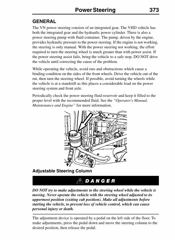
Power Steering 373POWER STEERING
GENERALThe VN power steering consists of an integrated gear. The VHD vehicle has both the integrated gear and the hydraulic power cylinder. There is also a power steering pump with fluid container. The pump, driven by the engine, provides hydraulic pressure to the power steering. If the engine is not working, the steering is only manual. With the power steering not working, the effort required to turn the steering wheel is much greater than with power assist. If the power steering assist fails, bring the vehicle to a safe stop. DO NOT drive the vehicle until correcting the cause of the problem.
While operating the vehicle, avoid ruts and obstructions which cause a binding condition on the sides of the front wheels. Drive the vehicle out of the rut, then turn the steering wheel. If possible, avoid turning the wheels while the vehicle is at a standstill as this places a considerable load on the power steering system and front axle.
Periodically check the power steering fluid reservoir and keep it filled to the proper level with the recommended fluid. See the “Operator's Manual, Maintenance and Engine” for more information.
Adjustable Steering Column
DO NOT try to make adjustments to the steering wheel while the vehicle is moving. Never operate the vehicle with the steering wheel adjusted to its uppermost position (exiting cab position). Make all adjustments before starting the vehicle, to prevent loss of vehicle control, which can cause personal injury or death.
The adjustment device is operated by a pedal on the left side of the floor. To make adjustments, press the pedal down and move the steering column to the desired position, then release the pedal.
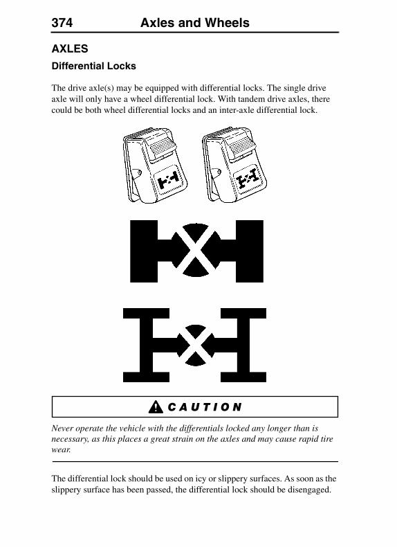
374 Axles and WheelsAXLES AND WHEELS
AXLES
Differential Locks
The drive axle(s) may be equipped with differential locks. The single drive axle will only have a wheel differential lock. With tandem drive axles, there could be both wheel differential locks and an inter-axle differential lock.
Never operate the vehicle with the differentials locked any longer than is necessary, as this places a great strain on the axles and may cause rapid tire wear.
The differential lock should be used on icy or slippery surfaces. As soon as the slippery surface has been passed, the differential lock should be disengaged.
Axles and Wheels 375
Differential locks must not, under any circumstances, be engaged when in a wheel-spin situation. Engage the locks ahead of the slippery area. If already slipping, stop the wheels, engage the locks and then continue. If the differential locks are engaged when the wheels are spinning, the differential will be damaged and the rear axle drive unit could possibly fail.
All efforts must be made to avoid spinning the wheels at high speeds on slippery surfaces. This is true whether the differential locks are engaged or not. Excessive wheel spin may result in failure of the cluster gears and other components found within the rear axle housing(s). If you are unable to obtain traction, engage the differentials locks as described below. If you are still unable to move the truck, seek assistance from a qualified tow operator."
Engaging the differential locks must always be done as follows (see “Dash Overview VN” on page 106 and “Dash Overview VHD” on page 108 for switch location):
1. Depress the clutch pedal. Wait for the drive wheels to stop spinning
2. Engage the differential lock
3. Engage a suitable gear
4. Carefully release the clutch pedal
DO NOT drive on dry, paved surface with the differential locks engaged. The vehicle will strive to maintain a straight line. Taking a curve with the differential locks engaged may cause an accident, leading to serious personal injury or death.
Under normal traction conditions, do not engage the differential locks. If at all possible, do not use the differential locks while taking a curve. With good traction and the differential locks engaged, the vehicle will be understeered and therefore will tend to drive straight in a curve. When using locks on good traction surface, drive cautiously and do not exceed 25 mph (40 km/h). Disengage the locks as soon as possible.
When the differential locks are disengaged, the couplings may be under tension. Disengage the locks by returning the switch to the OFF position. Help with the disengagement by briefly letting up on the accelerator to relieve the torque on the couplings.
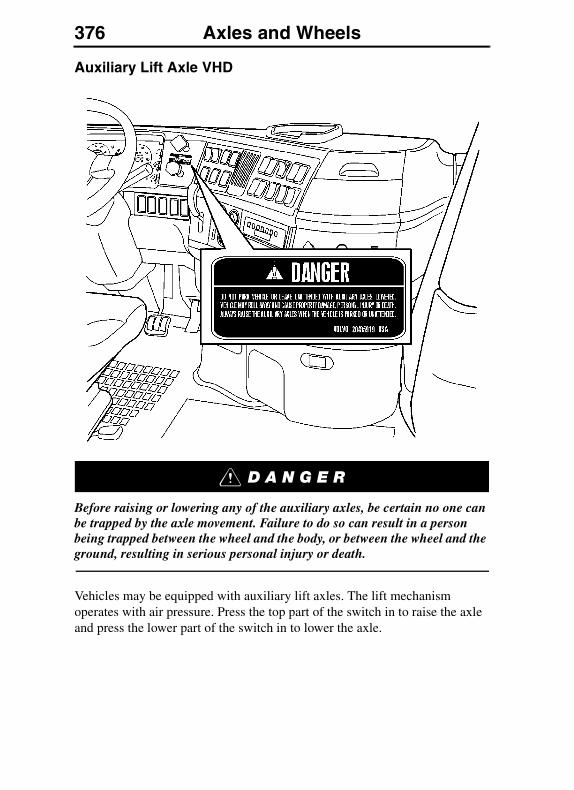
376 Axles and Wheels
Auxiliary Lift Axle VHD
Before raising or lowering any of the auxiliary axles, be certain no one can be trapped by the axle movement. Failure to do so can result in a person being trapped between the wheel and the body, or between the wheel and the ground, resulting in serious personal injury or death.
Vehicles may be equipped with auxiliary lift axles. The lift mechanism operates with air pressure. Press the top part of the switch in to raise the axle and press the lower part of the switch in to lower the axle.
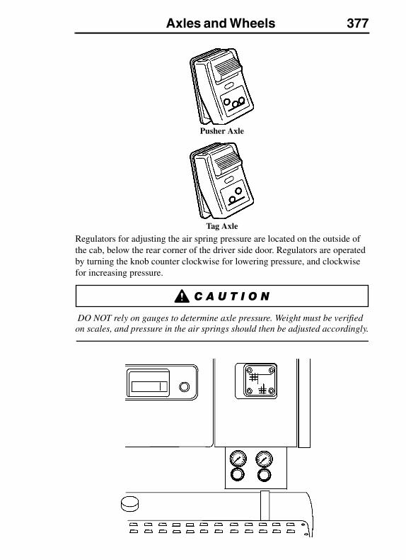
Axles and Wheels 377
Pusher Axle
Tag Axle
Regulators for adjusting the air spring pressure are located on the outside of the cab, below the rear corner of the driver side door. Regulators are operated by turning the knob counter clockwise for lowering pressure, and clockwise for increasing pressure.
DO NOT rely on gauges to determine axle pressure. Weight must be verified on scales, and pressure in the air springs should then be adjusted accordingly.
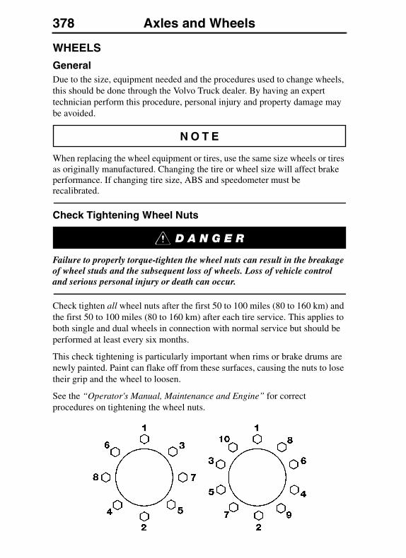
378 Axles and Wheels
WHEELS
GeneralDue to the size, equipment needed and the procedures used to change wheels, this should be done through the Volvo Truck dealer. By having an expert technician perform this procedure, personal injury and property damage may be avoided.
When replacing the wheel equipment or tires, use the same size wheels or tires as originally manufactured. Changing the tire or wheel size will affect brake performance. If changing tire size, ABS and speedometer must be recalibrated.
Check Tightening Wheel Nuts
Failure to properly torque-tighten the wheel nuts can result in the breakage of wheel studs and the subsequent loss of wheels. Loss of vehicle control and serious personal injury or death can occur.
Check tighten all wheel nuts after the first 50 to 100 miles (80 to 160 km) and the first 50 to 100 miles (80 to 160 km) after each tire service. This applies to both single and dual wheels in connection with normal service but should be performed at least every six months.
This check tightening is particularly important when rims or brake drums are newly painted. Paint can flake off from these surfaces, causing the nuts to lose their grip and the wheel to loosen.
See the “Operator's Manual, Maintenance and Engine” for correct procedures on tightening the wheel nuts.
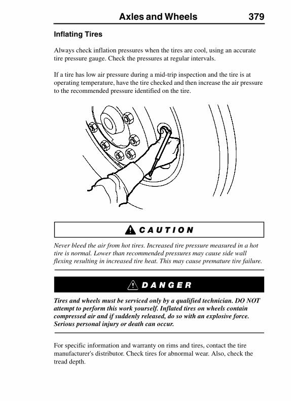
Axles and Wheels 379
Inflating Tires
Always check inflation pressures when the tires are cool, using an accurate tire pressure gauge. Check the pressures at regular intervals.
If a tire has low air pressure during a mid-trip inspection and the tire is at operating temperature, have the tire checked and then increase the air pressure to the recommended pressure identified on the tire.
Never bleed the air from hot tires. Increased tire pressure measured in a hot tire is normal. Lower than recommended pressures may cause side wall flexing resulting in increased tire heat. This may cause premature tire failure.
Tires and wheels must be serviced only by a qualified technician. DO NOT attempt to perform this work yourself. Inflated tires on wheels contain compressed air and if suddenly released, do so with an explosive force. Serious personal injury or death can occur.
For specific information and warranty on rims and tires, contact the tire manufacturer's distributor. Check tires for abnormal wear. Also, check the tread depth.
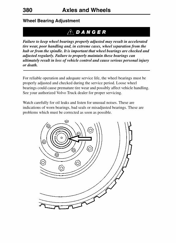
380 Axles and Wheels
Wheel Bearing Adjustment
Failure to keep wheel bearings properly adjusted may result in accelerated tire wear, poor handling and, in extreme cases, wheel separation from the hub or from the spindle. It is important that wheel bearings are checked and adjusted regularly. Failure to properly maintain these bearings can ultimately result in loss of vehicle control and cause serious personal injury or death.
For reliable operation and adequate service life, the wheel bearings must be properly adjusted and checked during the service period. Loose wheel bearings could cause premature tire wear and possibly affect vehicle handling. See your authorized Volvo Truck dealer for proper servicing.
Watch carefully for oil leaks and listen for unusual noises. These are indications of worn bearings, bad seals or misadjusted bearings. These are problems which must be corrected as soon as possible.
Fifth Wheel Instructions 381FIFTH WHEEL INSTRUCTIONS
FIFTH WHEEL GENERAL INFORMATION
Things to think about with trailer hook-up:
� Check the load distribution between axles.
� Always chock the trailer wheels.
� Grease the plate unless it is a low lube or no lube top plate.
� Verify visually that coupling has occurred.
� Verify visually that plungers have locked on slider.
� Check for slack between the 5th wheel and the trailer kingpin.
Always have all fifth wheel maintenance and repairs done by a qualified technician. An incorrect repair can cause the trailer to separate from the tractor causing an accident with serious personal injury or death.
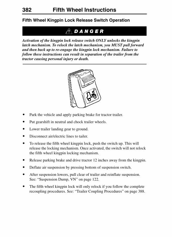
382 Fifth Wheel Instructions
Fifth Wheel Kingpin Lock Release Switch Operation
Activation of the kingpin lock release switch ONLY unlocks the kingpin latch mechanism. To relock the latch mechanism, you MUST pull forward and then back up to re-engage the kingpin lock mechanism. Failure to follow these instructions can result in separation of the trailer from the tractor causing personal injury or death.
� Park the vehicle and apply parking brake for tractor trailer.
� Put gearshift in neutral and chock trailer wheels.
� Lower trailer landing gear to ground.
� Disconnect air/electric lines to tailer.
� To release the fifth wheel kingpin lock, push the switch up. This will release the locking mechanism. Once activated, the switch will not relock the fifth wheel kingpin locking mechanism.
� Release parking brake and drive tractor 12 inches away from the kingpin.
� Deflate air suspension by pressing bottom of suspension switch.
� After suspension lowers, pull clear of trailer and reinflate suspension. See: “Suspension Dump, VN” on page 122.
� The fifth wheel kingpin lock will only relock if you follow the complete recoupling procedures. See: “Trailer Coupling Procedures” on page 388.
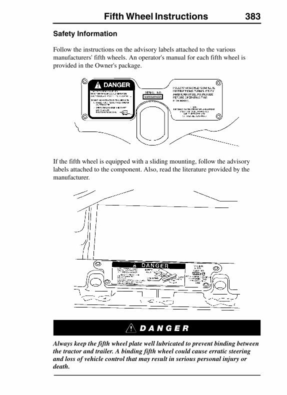
Fifth Wheel Instructions 383
Safety Information
Follow the instructions on the advisory labels attached to the various manufacturers' fifth wheels. An operator's manual for each fifth wheel is provided in the Owner's package.
If the fifth wheel is equipped with a sliding mounting, follow the advisory labels attached to the component. Also, read the literature provided by the manufacturer.
Always keep the fifth wheel plate well lubricated to prevent binding between the tractor and trailer. A binding fifth wheel could cause erratic steering and loss of vehicle control that may result in serious personal injury or death.
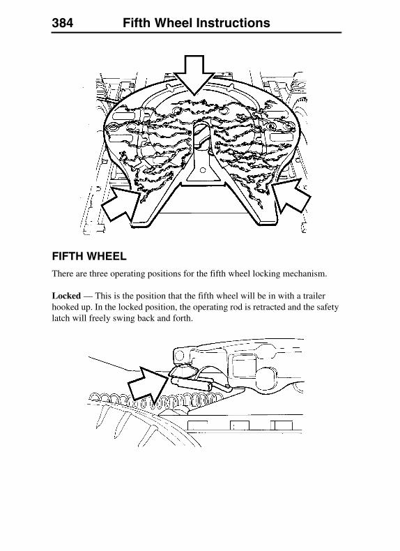
384 Fifth Wheel Instructions
FIFTH WHEELThere are three operating positions for the fifth wheel locking mechanism.
Locked — This is the position that the fifth wheel will be in with a trailer hooked up. In the locked position, the operating rod is retracted and the safety latch will freely swing back and forth.
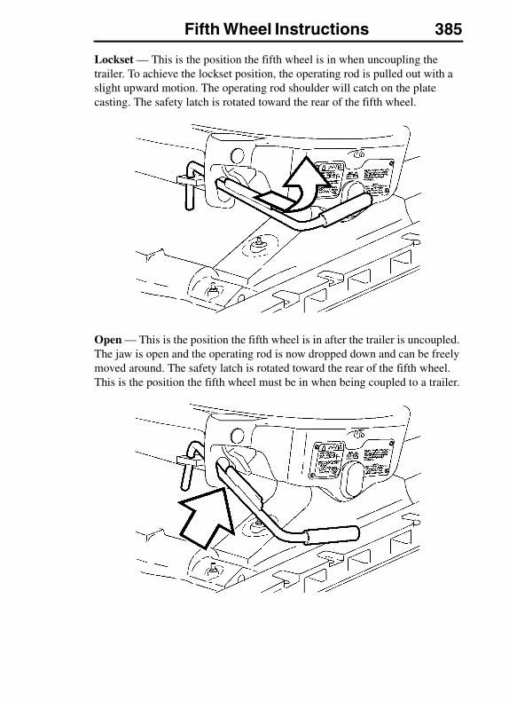
Fifth Wheel Instructions 385
Lockset — This is the position the fifth wheel is in when uncoupling the trailer. To achieve the lockset position, the operating rod is pulled out with a slight upward motion. The operating rod shoulder will catch on the plate casting. The safety latch is rotated toward the rear of the fifth wheel.
Open — This is the position the fifth wheel is in after the trailer is uncoupled. The jaw is open and the operating rod is now dropped down and can be freely moved around. The safety latch is rotated toward the rear of the fifth wheel. This is the position the fifth wheel must be in when being coupled to a trailer.
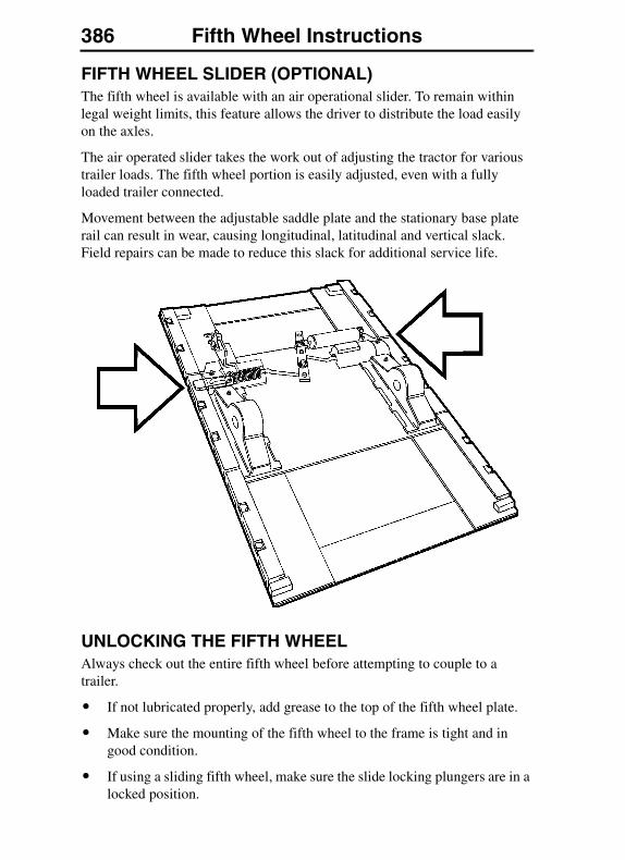
386 Fifth Wheel Instructions
FIFTH WHEEL SLIDER (OPTIONAL)The fifth wheel is available with an air operational slider. To remain within legal weight limits, this feature allows the driver to distribute the load easily on the axles.
The air operated slider takes the work out of adjusting the tractor for various trailer loads. The fifth wheel portion is easily adjusted, even with a fully loaded trailer connected.
Movement between the adjustable saddle plate and the stationary base plate rail can result in wear, causing longitudinal, latitudinal and vertical slack. Field repairs can be made to reduce this slack for additional service life.
UNLOCKING THE FIFTH WHEELAlways check out the entire fifth wheel before attempting to couple to a trailer.
� If not lubricated properly, add grease to the top of the fifth wheel plate.
� Make sure the mounting of the fifth wheel to the frame is tight and in good condition.
� If using a sliding fifth wheel, make sure the slide locking plungers are in a locked position.
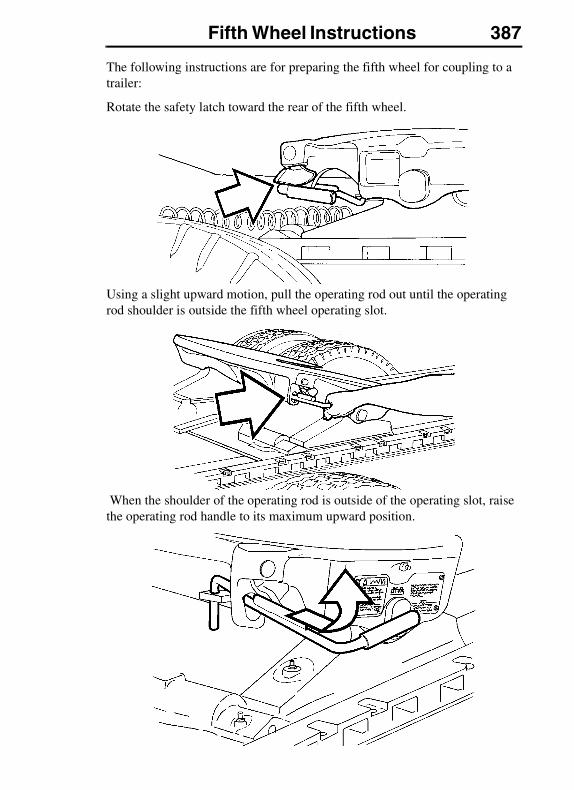
Fifth Wheel Instructions 387
The following instructions are for preparing the fifth wheel for coupling to a trailer:
Rotate the safety latch toward the rear of the fifth wheel.
Using a slight upward motion, pull the operating rod out until the operating rod shoulder is outside the fifth wheel operating slot.
When the shoulder of the operating rod is outside of the operating slot, raise the operating rod handle to its maximum upward position.
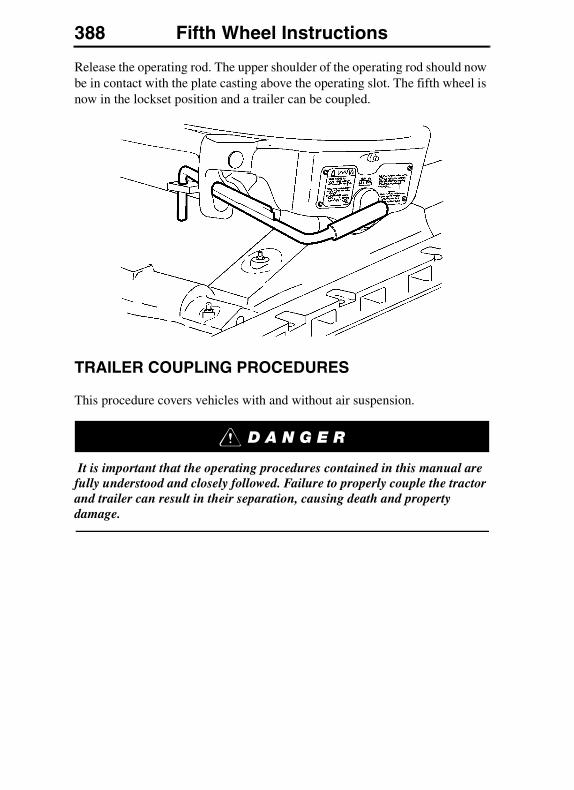
388 Fifth Wheel Instructions
Release the operating rod. The upper shoulder of the operating rod should now be in contact with the plate casting above the operating slot. The fifth wheel is now in the lockset position and a trailer can be coupled.
TRAILER COUPLING PROCEDURES
This procedure covers vehicles with and without air suspension.
It is important that the operating procedures contained in this manual are fully understood and closely followed. Failure to properly couple the tractor and trailer can result in their separation, causing death and property damage.
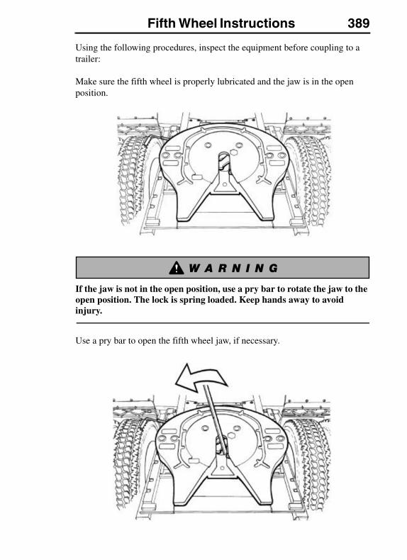
Fifth Wheel Instructions 389
Using the following procedures, inspect the equipment before coupling to a trailer:
Make sure the fifth wheel is properly lubricated and the jaw is in the open position.
If the jaw is not in the open position, use a pry bar to rotate the jaw to the open position. The lock is spring loaded. Keep hands away to avoid injury.
Use a pry bar to open the fifth wheel jaw, if necessary.
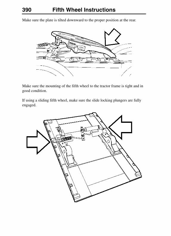
390 Fifth Wheel Instructions
Make sure the plate is tilted downward to the proper position at the rear.
Make sure the mounting of the fifth wheel to the tractor frame is tight and in good condition.
If using a sliding fifth wheel, make sure the slide locking plungers are fully engaged.
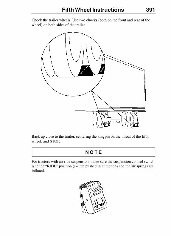
Fifth Wheel Instructions 391
Chock the trailer wheels. Use two chocks (both on the front and rear of the wheel) on both sides of the trailer.
Back up close to the trailer, centering the kingpin on the throat of the fifth wheel, and STOP.
For tractors with air ride suspension, make sure the suspension control switch is in the “RIDE” position (switch pushed in at the top) and the air springs are inflated.
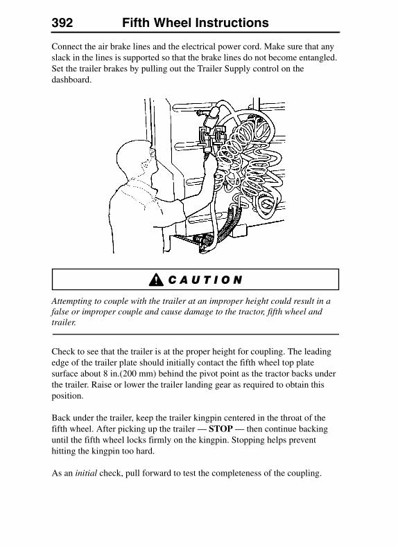
392 Fifth Wheel Instructions
Connect the air brake lines and the electrical power cord. Make sure that any slack in the lines is supported so that the brake lines do not become entangled. Set the trailer brakes by pulling out the Trailer Supply control on the dashboard.
Attempting to couple with the trailer at an improper height could result in a false or improper couple and cause damage to the tractor, fifth wheel and trailer.
Check to see that the trailer is at the proper height for coupling. The leading edge of the trailer plate should initially contact the fifth wheel top plate surface about 8 in.(200 mm) behind the pivot point as the tractor backs under the trailer. Raise or lower the trailer landing gear as required to obtain this position.
Back under the trailer, keep the trailer kingpin centered in the throat of the fifth wheel. After picking up the trailer — STOP — then continue backing until the fifth wheel locks firmly on the kingpin. Stopping helps prevent hitting the kingpin too hard.
As an initial check, pull forward to test the completeness of the coupling.
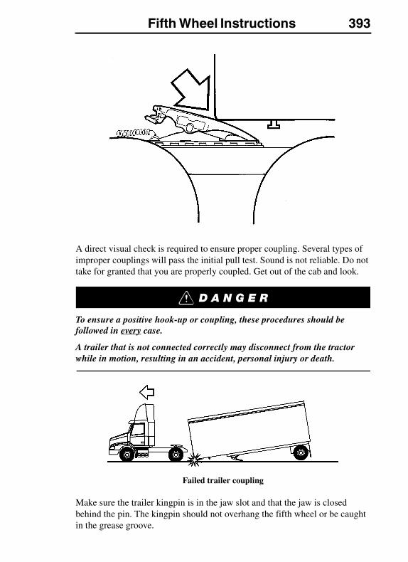
Fifth Wheel Instructions 393
A direct visual check is required to ensure proper coupling. Several types of improper couplings will pass the initial pull test. Sound is not reliable. Do not take for granted that you are properly coupled. Get out of the cab and look.
To ensure a positive hook-up or coupling, these procedures should be followed in every case.
A trailer that is not connected correctly may disconnect from the tractor while in motion, resulting in an accident, personal injury or death.
Failed trailer coupling
Make sure the trailer kingpin is in the jaw slot and that the jaw is closed behind the pin. The kingpin should not overhang the fifth wheel or be caught in the grease groove.
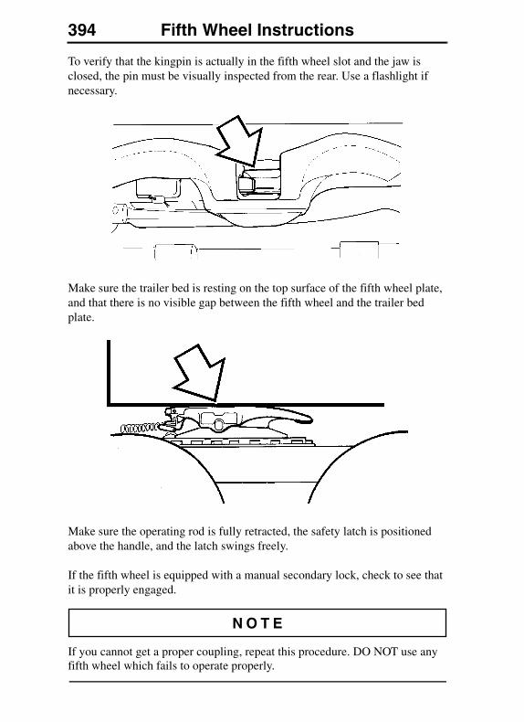
394 Fifth Wheel Instructions
To verify that the kingpin is actually in the fifth wheel slot and the jaw is closed, the pin must be visually inspected from the rear. Use a flashlight if necessary.
Make sure the trailer bed is resting on the top surface of the fifth wheel plate, and that there is no visible gap between the fifth wheel and the trailer bed plate.
Make sure the operating rod is fully retracted, the safety latch is positioned above the handle, and the latch swings freely.
If the fifth wheel is equipped with a manual secondary lock, check to see that it is properly engaged.
If you cannot get a proper coupling, repeat this procedure. DO NOT use any fifth wheel which fails to operate properly.
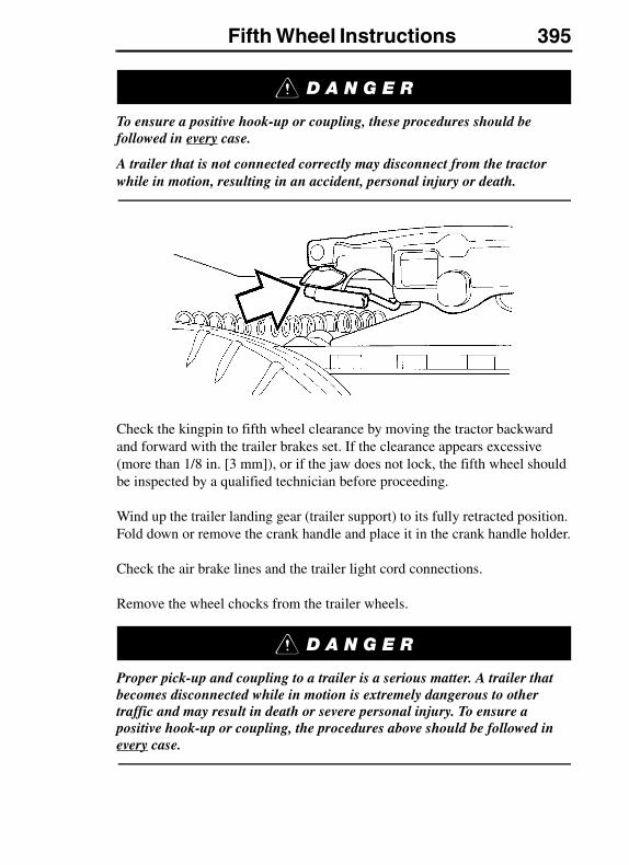
Fifth Wheel Instructions 395
To ensure a positive hook-up or coupling, these procedures should be followed in every case.
A trailer that is not connected correctly may disconnect from the tractor while in motion, resulting in an accident, personal injury or death.
Check the kingpin to fifth wheel clearance by moving the tractor backward and forward with the trailer brakes set. If the clearance appears excessive (more than 1/8 in. [3 mm]), or if the jaw does not lock, the fifth wheel should be inspected by a qualified technician before proceeding.
Wind up the trailer landing gear (trailer support) to its fully retracted position. Fold down or remove the crank handle and place it in the crank handle holder.
Check the air brake lines and the trailer light cord connections.
Remove the wheel chocks from the trailer wheels.
Proper pick-up and coupling to a trailer is a serious matter. A trailer that becomes disconnected while in motion is extremely dangerous to other traffic and may result in death or severe personal injury. To ensure a positive hook-up or coupling, the procedures above should be followed in every case.
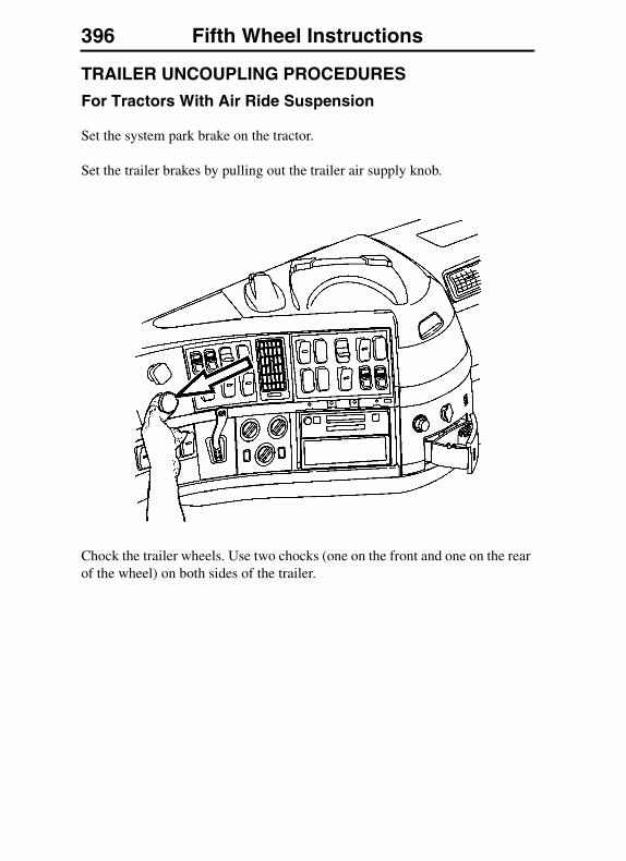
396 Fifth Wheel Instructions
TRAILER UNCOUPLING PROCEDURES
For Tractors With Air Ride Suspension
Set the system park brake on the tractor.
Set the trailer brakes by pulling out the trailer air supply knob.
Chock the trailer wheels. Use two chocks (one on the front and one on the rear of the wheel) on both sides of the trailer.

Fifth Wheel Instructions 397
Wind down the landing gear until it touches the ground and then give it a few extra turns in low gear. Do not raise the trailer off of the fifth wheel. Fold down or remove the crank handle and place it in the crank handle holder.
In poor ground conditions, it may be necessary to provide a stable base for the landing gear.
Disconnect the light cord and air brake lines. Use the dummy air couplings to keep foreign material from entering the brake lines.
Unlock the fifth wheel.
If the operating rod is too difficult to pull, back the tractor up slightly to relieve any kingpin load against the fifth wheel jaw.
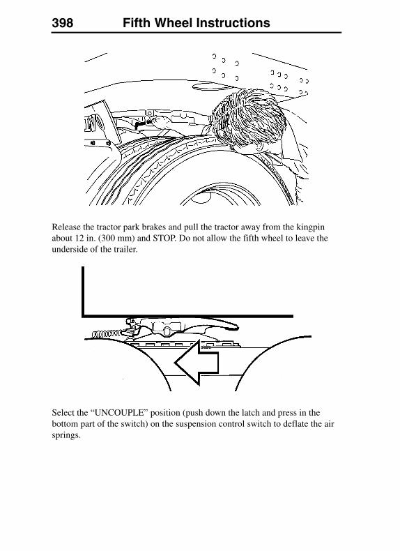
398 Fifth Wheel Instructions
Release the tractor park brakes and pull the tractor away from the kingpin about 12 in. (300 mm) and STOP. Do not allow the fifth wheel to leave the underside of the trailer.
Select the “UNCOUPLE” position (push down the latch and press in the bottom part of the switch) on the suspension control switch to deflate the air springs.
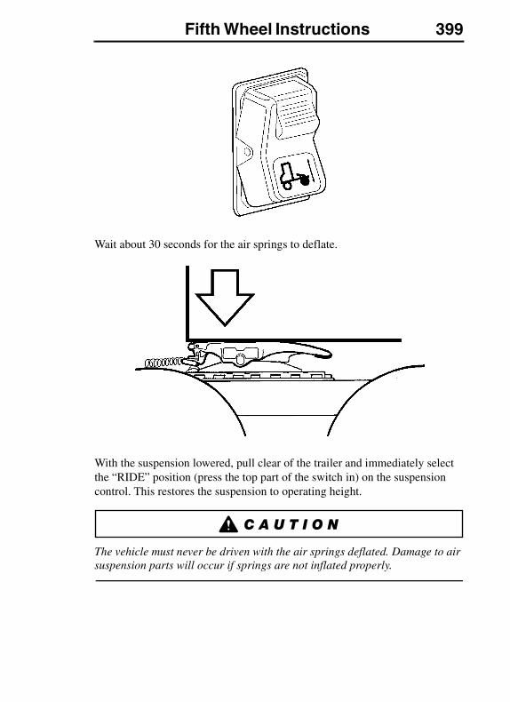
Fifth Wheel Instructions 399
Wait about 30 seconds for the air springs to deflate.
With the suspension lowered, pull clear of the trailer and immediately select the “RIDE” position (press the top part of the switch in) on the suspension control. This restores the suspension to operating height.
The vehicle must never be driven with the air springs deflated. Damage to air suspension parts will occur if springs are not inflated properly.
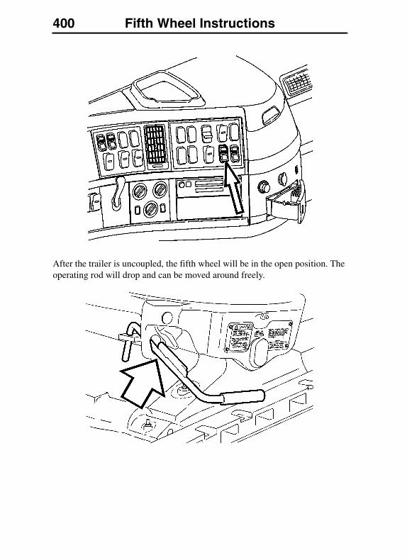
400 Fifth Wheel Instructions
After the trailer is uncoupled, the fifth wheel will be in the open position. The operating rod will drop and can be moved around freely.
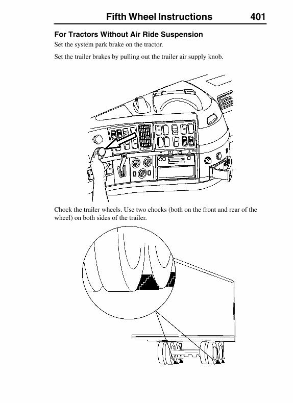
Fifth Wheel Instructions 401
For Tractors Without Air Ride SuspensionSet the system park brake on the tractor.
Set the trailer brakes by pulling out the trailer air supply knob.
Chock the trailer wheels. Use two chocks (both on the front and rear of the wheel) on both sides of the trailer.
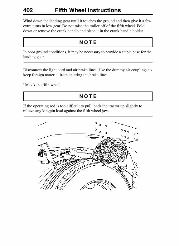
402 Fifth Wheel Instructions
Wind down the landing gear until it touches the ground and then give it a few extra turns in low gear. Do not raise the trailer off of the fifth wheel. Fold down or remove the crank handle and place it in the crank handle holder.
In poor ground conditions, it may be necessary to provide a stable base for the landing gear.
Disconnect the light cord and air brake lines. Use the dummy air couplings to keep foreign material from entering the brake lines.
Unlock the fifth wheel.
If the operating rod is too difficult to pull, back the tractor up slightly to relieve any kingpin load against the fifth wheel jaw.
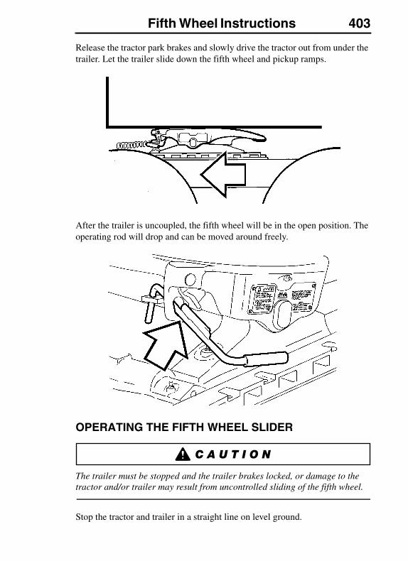
Fifth Wheel Instructions 403
Release the tractor park brakes and slowly drive the tractor out from under the trailer. Let the trailer slide down the fifth wheel and pickup ramps.
After the trailer is uncoupled, the fifth wheel will be in the open position. The operating rod will drop and can be moved around freely.
OPERATING THE FIFTH WHEEL SLIDER
The trailer must be stopped and the trailer brakes locked, or damage to the tractor and/or trailer may result from uncontrolled sliding of the fifth wheel.
Stop the tractor and trailer in a straight line on level ground.

404 Fifth Wheel Instructions
Lock the trailer brakes by pulling out the Trailer Supply knob.
Release the slide locking plungers by moving the switch to the “UNLOCK” position (press down the latch and push in the bottom part of the switch).
Check to see that both of the slide plungers have released. If the plungers do not come out, lower the landing gear to relieve the pressure on the plungers. Lowering the landing gear will also allow the fifth wheel to slide easier.
Slowly drive the tractor forward or backward to position the fifth wheel.
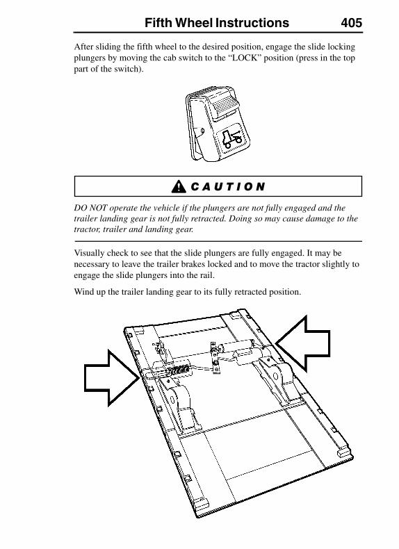
Fifth Wheel Instructions 405
After sliding the fifth wheel to the desired position, engage the slide locking plungers by moving the cab switch to the “LOCK” position (press in the top part of the switch).
DO NOT operate the vehicle if the plungers are not fully engaged and the trailer landing gear is not fully retracted. Doing so may cause damage to the tractor, trailer and landing gear.
Visually check to see that the slide plungers are fully engaged. It may be necessary to leave the trailer brakes locked and to move the tractor slightly to engage the slide plungers into the rail.
Wind up the trailer landing gear to its fully retracted position.
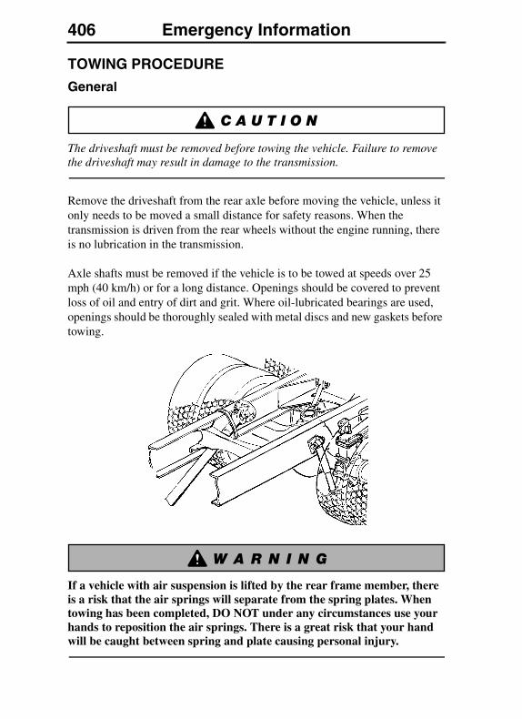
406 Emergency InformationEMERGENCY INFORMATION
TOWING PROCEDURE
General
The driveshaft must be removed before towing the vehicle. Failure to remove the driveshaft may result in damage to the transmission.
Remove the driveshaft from the rear axle before moving the vehicle, unless it only needs to be moved a small distance for safety reasons. When the transmission is driven from the rear wheels without the engine running, there is no lubrication in the transmission.
Axle shafts must be removed if the vehicle is to be towed at speeds over 25 mph (40 km/h) or for a long distance. Openings should be covered to prevent loss of oil and entry of dirt and grit. Where oil-lubricated bearings are used, openings should be thoroughly sealed with metal discs and new gaskets before towing.
If a vehicle with air suspension is lifted by the rear frame member, there is a risk that the air springs will separate from the spring plates. When towing has been completed, DO NOT under any circumstances use your hands to reposition the air springs. There is a great risk that your hand will be caught between spring and plate causing personal injury.
Emergency Information 407
DO NOT tow a vehicle backwards when equipped with roof air fairings. The fairings act as an air scoop and may break off. Failure to follow this warning may lead to personal injury and vehicle damage.
Vehicles with air fairings are tall. Make sure that the total height of the vehicle, when it is raised up behind the wrecker, does not exceed the maximum allowed height for local underpasses. Failure to follow this instruction may lead to personal injury and vehicle damage.
The vehicle may now be towed. It is recommended that a wrecker with a lift bar is used since the service brakes will not function. The system must be filled with air to release the parking brake or follow the mechanical spring brake caging procedures on “Caging Spring Brake Chambers” on page 411.
The power steering does not function when towing a vehicle with a disabled engine.
Towing Instructions
If the vehicle becomes disabled, it is very important to tow it properly. Failure to do so can cause damage to the frame and body parts. Follow the instructions below to avoid damage.
In the event that the vehicle cannot be reached to place the wrecker lift bar under the front axle, use the optional tow eyes. The front tow eyes are used as a point at the front of the vehicle where the vehicle can be pulled.
DO NOT use the tow eyes for raising the front of the vehicle; the tow eyes can break. DO NOT crawl under a vehicle suspended by tow eyes. Failure to follow these instructions can result in serious personal injury or death.

408 Emergency Information
On day cab models, the tow eyes are stored bolted to the back of the cab wall.
On sleeper cab models, the tow eyes are stored bolted to the back wall of the luggage compartment wall.
DO NOT lift or tow vehicle as shown in this illustration.

Emergency Information 409
The tow eyes are held in place when mounted on the front of the vehicle by tractor pins. These pins are stored in the tow eye mounting holes when not being used.
If the vehicle has the optional rock guard installed, insert the lock pin into the tow hook from the opposite side during installation.
In the new model VN trucks if the truck has the optional rock/stone guard installed, then the driver will have to insert the lock pin into the tow hook from the opposite side during installation.
When the vehicle is located properly, lift the front and locate the lift bar under the front axle and secure. Using the front axle for towing minimizes the possibility for damage to the vehicle body, frame and suspension.
When the driveshaft or axle shafts are reinstalled, make sure the nuts are tightened to the correct torques. Also make sure the axle shafts are installed in the proper sides, with the left shaft in the left side and the right shaft in the right side.
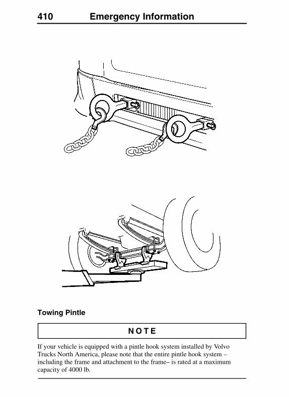
410 Emergency Information
Towing Pintle
If your vehicle is equipped with a pintle hook system installed by Volvo Trucks North America, please note that the entire pintle hook system – including the frame and attachment to the frame– is rated at a maximum capacity of 4000 lb.
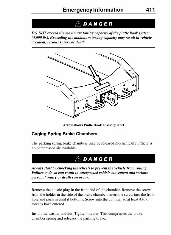
Emergency Information 411
DO NOT exceed the maximum towing capacity of the pintle hook system (4,000 lb.). Exceeding the maximum towing capacity may result in vehicle accident, serious Injury or death.
Arrow shows Pintle Hook advisory label
Caging Spring Brake Chambers
The parking spring brake chambers may be released mechanically if there is no compressed air available.
Always start by chocking the wheels to prevent the vehicle from rolling. Failure to do so can result in unexpected vehicle movement and serious personal injury or death can occur.
Remove the plastic plug in the front end of the chamber. Remove the screw from the holder in the side of the brake chamber. Insert the screw into the front hole and push in until it bottoms. Screw into the cylinder so at least 4 to 6 threads have entered.
Install the washer and nut. Tighten the nut. This compresses the brake chamber spring and releases the parking brake.
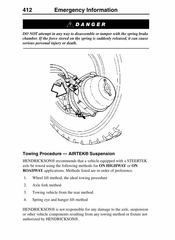
412 Emergency Information
DO NOT attempt in any way to disassemble or tamper with the spring brake chamber. If the force stored on the spring is suddenly released, it can cause serious personal injury or death.
Towing Procedure — AIRTEK® Suspension
HENDRICKSON® recommends that a vehicle equipped with a STEERTEK axle be towed using the following methods for ON HIGHWAY or ON ROADWAY applications. Methods listed are in order of preference.
1. Wheel lift method, the ideal towing procedure
2. Axle fork method
3. Towing vehicle from the rear method
4. Spring eye and hanger lift method
HENDRICKSON® is not responsible for any damage to the axle, suspension or other vehicle components resulting from any towing method or fixture not authorized by HENDRICKSON®.
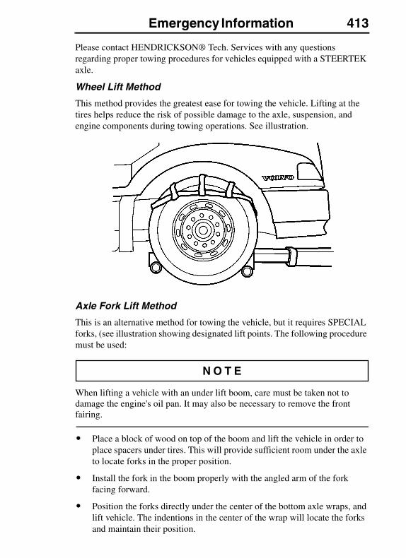
Emergency Information 413
Please contact HENDRICKSON® Tech. Services with any questions regarding proper towing procedures for vehicles equipped with a STEERTEK axle.
Wheel Lift Method
This method provides the greatest ease for towing the vehicle. Lifting at the tires helps reduce the risk of possible damage to the axle, suspension, and engine components during towing operations. See illustration.
Axle Fork Lift Method
This is an alternative method for towing the vehicle, but it requires SPECIAL forks, (see illustration showing designated lift points. The following procedure must be used:
When lifting a vehicle with an under lift boom, care must be taken not to damage the engine's oil pan. It may also be necessary to remove the front fairing.
� Place a block of wood on top of the boom and lift the vehicle in order to place spacers under tires. This will provide sufficient room under the axle to locate forks in the proper position.
� Install the fork in the boom properly with the angled arm of the fork facing forward.
� Position the forks directly under the center of the bottom axle wraps, and lift vehicle. The indentions in the center of the wrap will locate the forks and maintain their position.
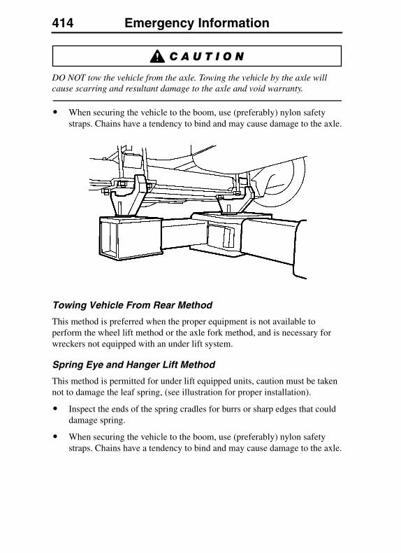
414 Emergency Information
DO NOT tow the vehicle from the axle. Towing the vehicle by the axle will cause scarring and resultant damage to the axle and void warranty.
� When securing the vehicle to the boom, use (preferably) nylon safety straps. Chains have a tendency to bind and may cause damage to the axle.
Towing Vehicle From Rear Method
This method is preferred when the proper equipment is not available to perform the wheel lift method or the axle fork method, and is necessary for wreckers not equipped with an under lift system.
Spring Eye and Hanger Lift Method
This method is permitted for under lift equipped units, caution must be taken not to damage the leaf spring, (see illustration for proper installation).
� Inspect the ends of the spring cradles for burrs or sharp edges that could damage spring.
� When securing the vehicle to the boom, use (preferably) nylon safety straps. Chains have a tendency to bind and may cause damage to the axle.

Emergency Information 415
When lifting a vehicle with the under lift boom (see illustration) care must be taken not to damage the engine oil pan. It may be necessary to remove front fairing. If necessary, place a block of wood between the top of the boom and the bottom of the axle.
Off Roadway Towing Method
When a truck is disabled and equipped with a STEERTEK axle, care must be taken to ensure there is no damage to the suspension when towing the vehicle.
The use of a tow strap is necessary to tow a disabled truck into a repair facility. The tow straps should be connected to the tow hooks provided by the manufacturer at the front of the bumper. If the use of tow hooks is not an option, then a tow strap may be wrapped around the front axle (see illustration) in a manner that is acceptable for towing the vehicle into the shop.
DO NOT use a tow chain around the front axle to tow the vehicle, doing so will damage the axle and void warranty. See illustration.
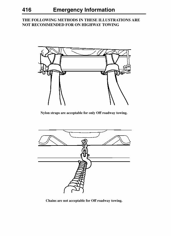
416 Emergency Information
THE FOLLOWING METHODS IN THESE ILLUSTRATIONS ARE NOT RECOMMENDED FOR ON HIGHWAY TOWING
Nylon straps are acceptable for only Off roadway towing.
Chains are not acceptable for Off roadway towing.
Service Information 417SERVICE INFORMATION
SERVICE ASSISTANCE AND MANUALS
Your authorized Volvo Truck dealer is trained and equipped to perform expert service on your Volvo vehicle. Your dealer has direct access to Volvo Trucks North America for technical help, parts or service information.
There is also a direct number to Volvo Action Service (VAS), staffed 24 hours a day, if you are in need of assistance. The number to the Customer Support Center is: 1 (800) 528–6586 [or (800) 52–VOLVO]. Also on the internet: www.vas.volvo.com
VAS offers:
Delivery Assurance — If you need roadside assistance, VAS can arrange for load forwarding or equipment rental.
Personal Assurance — Trained staff for handling any vehicle problems.
Uptime Assurance — VAS will locate the nearest service provider and guarantee payment so you can get on the road as soon as possible.
Price Assurance — VAS audits service and parts billing to ensure guaranteed labor rates and preferred parts pricing for Volvo components.
To order a single Service Manual or a Service Manual Set for your vehicle, contact your authorized Volvo Truck dealer.
In order to handle the request correctly, you must give the model, year and VIN (last six digits of VIN only).
(For VIN location, see “Identification and Labels” on page 27).
Service Manual prices will vary depending on the make and model of engine in the vehicle. (A Cummins engine manual is included in your introductory owner's package).
Please allow 30 days for delivery of Manual.
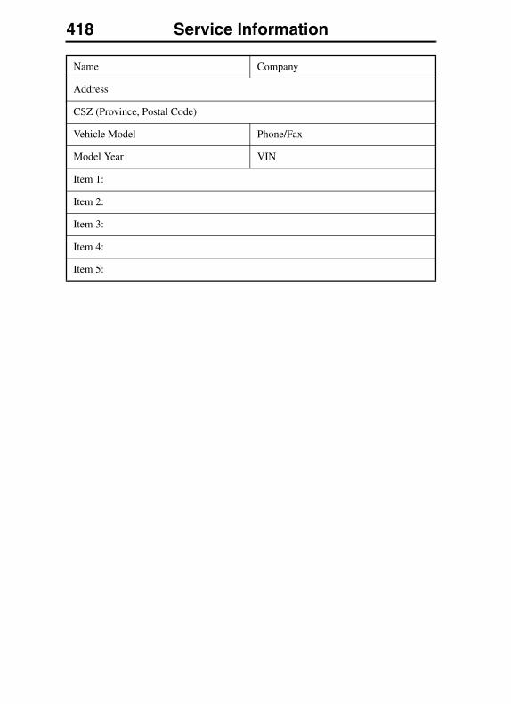
418 Service Information
Name Company
Address
CSZ (Province, Postal Code)
Vehicle Model Phone/Fax
Model Year VIN
Item 1:
Item 2:
Item 3:
Item 4:
Item 5:
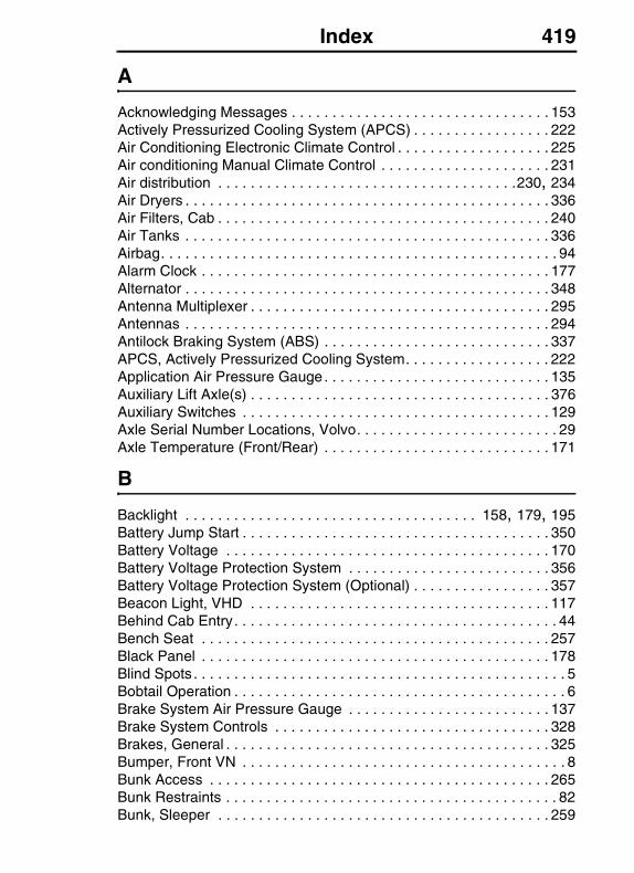
Index 419
A
Acknowledging Messages . . . . . . . . . . . . . . . . . . . . . . . . . . . . . . . . 153Actively Pressurized Cooling System (APCS) . . . . . . . . . . . . . . . . . 222Air Conditioning Electronic Climate Control . . . . . . . . . . . . . . . . . . . 225Air conditioning Manual Climate Control . . . . . . . . . . . . . . . . . . . . . 231Air distribution . . . . . . . . . . . . . . . . . . . . . . . . . . . . . . . . . . . . .230, 234Air Dryers . . . . . . . . . . . . . . . . . . . . . . . . . . . . . . . . . . . . . . . . . . . . . 336Air Filters, Cab . . . . . . . . . . . . . . . . . . . . . . . . . . . . . . . . . . . . . . . . . 240Air Tanks . . . . . . . . . . . . . . . . . . . . . . . . . . . . . . . . . . . . . . . . . . . . . 336Airbag. . . . . . . . . . . . . . . . . . . . . . . . . . . . . . . . . . . . . . . . . . . . . . . . . 94Alarm Clock . . . . . . . . . . . . . . . . . . . . . . . . . . . . . . . . . . . . . . . . . . . 177Alternator . . . . . . . . . . . . . . . . . . . . . . . . . . . . . . . . . . . . . . . . . . . . . 348Antenna Multiplexer . . . . . . . . . . . . . . . . . . . . . . . . . . . . . . . . . . . . . 295Antennas . . . . . . . . . . . . . . . . . . . . . . . . . . . . . . . . . . . . . . . . . . . . . 294Antilock Braking System (ABS) . . . . . . . . . . . . . . . . . . . . . . . . . . . . 337APCS, Actively Pressurized Cooling System. . . . . . . . . . . . . . . . . . 222Application Air Pressure Gauge. . . . . . . . . . . . . . . . . . . . . . . . . . . . 135Auxiliary Lift Axle(s) . . . . . . . . . . . . . . . . . . . . . . . . . . . . . . . . . . . . . 376Auxiliary Switches . . . . . . . . . . . . . . . . . . . . . . . . . . . . . . . . . . . . . . 129Axle Serial Number Locations, Volvo. . . . . . . . . . . . . . . . . . . . . . . . . 29Axle Temperature (Front/Rear) . . . . . . . . . . . . . . . . . . . . . . . . . . . . 171
B
Backlight . . . . . . . . . . . . . . . . . . . . . . . . . . . . . . . . . . . . 158, 179, 195Battery Jump Start . . . . . . . . . . . . . . . . . . . . . . . . . . . . . . . . . . . . . . 350Battery Voltage . . . . . . . . . . . . . . . . . . . . . . . . . . . . . . . . . . . . . . . . 170Battery Voltage Protection System . . . . . . . . . . . . . . . . . . . . . . . . . 356Battery Voltage Protection System (Optional) . . . . . . . . . . . . . . . . . 357Beacon Light, VHD . . . . . . . . . . . . . . . . . . . . . . . . . . . . . . . . . . . . . 117Behind Cab Entry. . . . . . . . . . . . . . . . . . . . . . . . . . . . . . . . . . . . . . . . 44Bench Seat . . . . . . . . . . . . . . . . . . . . . . . . . . . . . . . . . . . . . . . . . . . 257Black Panel . . . . . . . . . . . . . . . . . . . . . . . . . . . . . . . . . . . . . . . . . . . 178Blind Spots . . . . . . . . . . . . . . . . . . . . . . . . . . . . . . . . . . . . . . . . . . . . . . 5Bobtail Operation . . . . . . . . . . . . . . . . . . . . . . . . . . . . . . . . . . . . . . . . . 6Brake System Air Pressure Gauge . . . . . . . . . . . . . . . . . . . . . . . . . 137Brake System Controls . . . . . . . . . . . . . . . . . . . . . . . . . . . . . . . . . . 328Brakes, General . . . . . . . . . . . . . . . . . . . . . . . . . . . . . . . . . . . . . . . . 325Bumper, Front VN . . . . . . . . . . . . . . . . . . . . . . . . . . . . . . . . . . . . . . . . 8Bunk Access . . . . . . . . . . . . . . . . . . . . . . . . . . . . . . . . . . . . . . . . . . 265Bunk Restraints . . . . . . . . . . . . . . . . . . . . . . . . . . . . . . . . . . . . . . . . . 82Bunk, Sleeper . . . . . . . . . . . . . . . . . . . . . . . . . . . . . . . . . . . . . . . . . 259
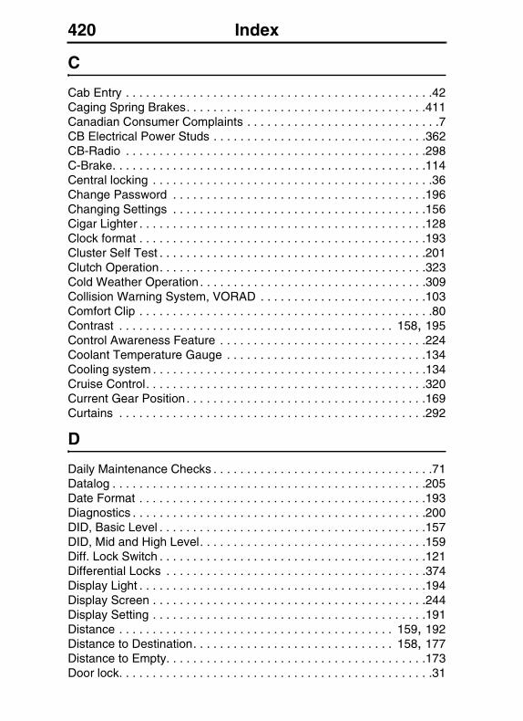
420 Index
C
Cab Entry . . . . . . . . . . . . . . . . . . . . . . . . . . . . . . . . . . . . . . . . . . . . . .42Caging Spring Brakes. . . . . . . . . . . . . . . . . . . . . . . . . . . . . . . . . . . .411Canadian Consumer Complaints . . . . . . . . . . . . . . . . . . . . . . . . . . . . .7CB Electrical Power Studs . . . . . . . . . . . . . . . . . . . . . . . . . . . . . . . .362CB-Radio . . . . . . . . . . . . . . . . . . . . . . . . . . . . . . . . . . . . . . . . . . . . .298C-Brake. . . . . . . . . . . . . . . . . . . . . . . . . . . . . . . . . . . . . . . . . . . . . . .114Central locking . . . . . . . . . . . . . . . . . . . . . . . . . . . . . . . . . . . . . . . . . .36Change Password . . . . . . . . . . . . . . . . . . . . . . . . . . . . . . . . . . . . . .196Changing Settings . . . . . . . . . . . . . . . . . . . . . . . . . . . . . . . . . . . . . .156Cigar Lighter . . . . . . . . . . . . . . . . . . . . . . . . . . . . . . . . . . . . . . . . . . .128Clock format . . . . . . . . . . . . . . . . . . . . . . . . . . . . . . . . . . . . . . . . . . .193Cluster Self Test . . . . . . . . . . . . . . . . . . . . . . . . . . . . . . . . . . . . . . . .201Clutch Operation. . . . . . . . . . . . . . . . . . . . . . . . . . . . . . . . . . . . . . . .323Cold Weather Operation . . . . . . . . . . . . . . . . . . . . . . . . . . . . . . . . . .309Collision Warning System, VORAD . . . . . . . . . . . . . . . . . . . . . . . . .103Comfort Clip . . . . . . . . . . . . . . . . . . . . . . . . . . . . . . . . . . . . . . . . . . . .80Contrast . . . . . . . . . . . . . . . . . . . . . . . . . . . . . . . . . . . . . . . . . 158, 195Control Awareness Feature . . . . . . . . . . . . . . . . . . . . . . . . . . . . . . .224Coolant Temperature Gauge . . . . . . . . . . . . . . . . . . . . . . . . . . . . . .134Cooling system . . . . . . . . . . . . . . . . . . . . . . . . . . . . . . . . . . . . . . . . .134Cruise Control. . . . . . . . . . . . . . . . . . . . . . . . . . . . . . . . . . . . . . . . . .320Current Gear Position . . . . . . . . . . . . . . . . . . . . . . . . . . . . . . . . . . . .169Curtains . . . . . . . . . . . . . . . . . . . . . . . . . . . . . . . . . . . . . . . . . . . . . .292
D
Daily Maintenance Checks . . . . . . . . . . . . . . . . . . . . . . . . . . . . . . . . .71Datalog . . . . . . . . . . . . . . . . . . . . . . . . . . . . . . . . . . . . . . . . . . . . . . .205Date Format . . . . . . . . . . . . . . . . . . . . . . . . . . . . . . . . . . . . . . . . . . .193Diagnostics . . . . . . . . . . . . . . . . . . . . . . . . . . . . . . . . . . . . . . . . . . . .200DID, Basic Level . . . . . . . . . . . . . . . . . . . . . . . . . . . . . . . . . . . . . . . .157DID, Mid and High Level. . . . . . . . . . . . . . . . . . . . . . . . . . . . . . . . . .159Diff. Lock Switch . . . . . . . . . . . . . . . . . . . . . . . . . . . . . . . . . . . . . . . .121Differential Locks . . . . . . . . . . . . . . . . . . . . . . . . . . . . . . . . . . . . . . .374Display Light . . . . . . . . . . . . . . . . . . . . . . . . . . . . . . . . . . . . . . . . . . .194Display Screen . . . . . . . . . . . . . . . . . . . . . . . . . . . . . . . . . . . . . . . . .244Display Setting . . . . . . . . . . . . . . . . . . . . . . . . . . . . . . . . . . . . . . . . .191Distance . . . . . . . . . . . . . . . . . . . . . . . . . . . . . . . . . . . . . . . . . 159, 192Distance to Destination. . . . . . . . . . . . . . . . . . . . . . . . . . . . . . 158, 177Distance to Empty. . . . . . . . . . . . . . . . . . . . . . . . . . . . . . . . . . . . . . .173Door lock. . . . . . . . . . . . . . . . . . . . . . . . . . . . . . . . . . . . . . . . . . . . . . .31
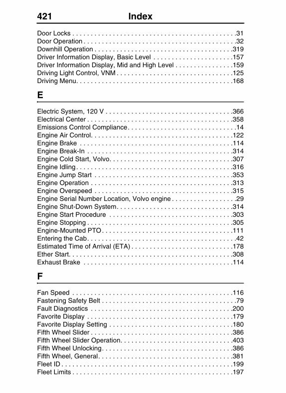
421 Index
Door Locks . . . . . . . . . . . . . . . . . . . . . . . . . . . . . . . . . . . . . . . . . . . . .31Door Operation . . . . . . . . . . . . . . . . . . . . . . . . . . . . . . . . . . . . . . . . . .32Downhill Operation . . . . . . . . . . . . . . . . . . . . . . . . . . . . . . . . . . . . . .319Driver Information Display, Basic Level . . . . . . . . . . . . . . . . . . . . . .157Driver Information Display, Mid and High Level . . . . . . . . . . . . . . . .159Driving Light Control, VNM . . . . . . . . . . . . . . . . . . . . . . . . . . . . . . . .125Driving Menu. . . . . . . . . . . . . . . . . . . . . . . . . . . . . . . . . . . . . . . . . . .168
E
Electric System, 120 V . . . . . . . . . . . . . . . . . . . . . . . . . . . . . . . . . . .366Electrical Center . . . . . . . . . . . . . . . . . . . . . . . . . . . . . . . . . . . . . . . .358Emissions Control Compliance. . . . . . . . . . . . . . . . . . . . . . . . . . . . . .14Engine Air Control. . . . . . . . . . . . . . . . . . . . . . . . . . . . . . . . . . . . . . .122Engine Brake . . . . . . . . . . . . . . . . . . . . . . . . . . . . . . . . . . . . . . . . . .114Engine Break-In . . . . . . . . . . . . . . . . . . . . . . . . . . . . . . . . . . . . . . . .314Engine Cold Start, Volvo. . . . . . . . . . . . . . . . . . . . . . . . . . . . . . . . . .307Engine Idling . . . . . . . . . . . . . . . . . . . . . . . . . . . . . . . . . . . . . . . . . . .316Engine Jump Start . . . . . . . . . . . . . . . . . . . . . . . . . . . . . . . . . . . . . .353Engine Operation . . . . . . . . . . . . . . . . . . . . . . . . . . . . . . . . . . . . . . .313Engine Overspeed . . . . . . . . . . . . . . . . . . . . . . . . . . . . . . . . . . . . . .315Engine Serial Number Location, Volvo engine . . . . . . . . . . . . . . . . . .29Engine Shut-Down System. . . . . . . . . . . . . . . . . . . . . . . . . . . . . . . .314Engine Start Procedure . . . . . . . . . . . . . . . . . . . . . . . . . . . . . . . . . .303Engine Stopping . . . . . . . . . . . . . . . . . . . . . . . . . . . . . . . . . . . . . . . .305Engine-Mounted PTO. . . . . . . . . . . . . . . . . . . . . . . . . . . . . . . . . . . .111Entering the Cab. . . . . . . . . . . . . . . . . . . . . . . . . . . . . . . . . . . . . . . . .42Estimated Time of Arrival (ETA) . . . . . . . . . . . . . . . . . . . . . . . . . . . .178Ether Start. . . . . . . . . . . . . . . . . . . . . . . . . . . . . . . . . . . . . . . . . . . . .308Exhaust Brake . . . . . . . . . . . . . . . . . . . . . . . . . . . . . . . . . . . . . . . . .114
F
Fan Speed . . . . . . . . . . . . . . . . . . . . . . . . . . . . . . . . . . . . . . . . . . . .116Fastening Safety Belt . . . . . . . . . . . . . . . . . . . . . . . . . . . . . . . . . . . . .79Fault Diagnostics . . . . . . . . . . . . . . . . . . . . . . . . . . . . . . . . . . . . . . .200Favorite Display . . . . . . . . . . . . . . . . . . . . . . . . . . . . . . . . . . . . . . . .179Favorite Display Setting . . . . . . . . . . . . . . . . . . . . . . . . . . . . . . . . . .180Fifth Wheel Slider . . . . . . . . . . . . . . . . . . . . . . . . . . . . . . . . . . . . . . .386Fifth Wheel Slider Operation. . . . . . . . . . . . . . . . . . . . . . . . . . . . . . .403Fifth Wheel Unlocking. . . . . . . . . . . . . . . . . . . . . . . . . . . . . . . . . . . .386Fifth Wheel, General. . . . . . . . . . . . . . . . . . . . . . . . . . . . . . . . . . . . .381Fleet ID . . . . . . . . . . . . . . . . . . . . . . . . . . . . . . . . . . . . . . . . . . . . . . .199Fleet Limits . . . . . . . . . . . . . . . . . . . . . . . . . . . . . . . . . . . . . . . . . . . .197
422 Index
Fog light Control, VNM . . . . . . . . . . . . . . . . . . . . . . . . . . . . . . . . . . .125Fog lights, VNL . . . . . . . . . . . . . . . . . . . . . . . . . . . . . . . . . . . . . . . . .125Foot Brake . . . . . . . . . . . . . . . . . . . . . . . . . . . . . . . . . . . . . . . . . . . .328Frame Alterations . . . . . . . . . . . . . . . . . . . . . . . . . . . . . . . . . . . . . . . .14Front Brake System Air Pressure Gauge . . . . . . . . . . . . . . . . . . . . .137Front-Engine Mounted PTO . . . . . . . . . . . . . . . . . . . . . . . . . . . . . . .112Fuel Consumption. . . . . . . . . . . . . . . . . . . . . . . . . . . . . . . . . . . . . . .192Fuel Economy. . . . . . . . . . . . . . . . . . . . . . . . . . . . . . . . . . . . . . . . . .173Fuel Level Gauge . . . . . . . . . . . . . . . . . . . . . . . . . . . . . . . . . . . . . . .135Fuel Parking Heater . . . . . . . . . . . . . . . . . . . . . . . . . . . . . . . . . . . . .251Fueling . . . . . . . . . . . . . . . . . . . . . . . . . . . . . . . . . . . . . . . . . . . . . . .322
G
Gear Position Current . . . . . . . . . . . . . . . . . . . . . . . . . . . . . . . . . . . .169
H
Headlight Bulb Changing VNL . . . . . . . . . . . . . . . . . . . . . . . . . . . . .372Headlight Bulb Changing, VNM . . . . . . . . . . . . . . . . . . . . . . . . . . . .370Heated rear view mirrors . . . . . . . . . . . . . . . . . . . . . . . . . . . . . . . . . .34High Altitude Operation. . . . . . . . . . . . . . . . . . . . . . . . . . . . . . . . . . .319Hood Latch, VNM 200 Day Cab, Short Fairing. . . . . . . . . . . . . . . . . .55Hood Opening. . . . . . . . . . . . . . . . . . . . . . . . . . . . . . . . . . . . . . . . . . .52
I
Idle Adjustment . . . . . . . . . . . . . . . . . . . . . . . . . . . . . . . . . . . . . . . . .317Idle Percent. . . . . . . . . . . . . . . . . . . . . . . . . . . . . . . . . . . . . . . . . . . .174Idle Shutdown. . . . . . . . . . . . . . . . . . . . . . . . . . . . . . . . . . . . . . . . . .318Idling . . . . . . . . . . . . . . . . . . . . . . . . . . . . . . . . . . . . . . . . . . . . . . . . .316Ignition Switch. . . . . . . . . . . . . . . . . . . . . . . . . . . . . . . . . . . . . . . . . .306Immobilizer Feature . . . . . . . . . . . . . . . . . . . . . . . . . . . . . . . . . . . . .218Info Display . . . . . . . . . . . . . . . . . . . . . . . . . . . . . . . . . . . . . . . . . . . .178Information messages . . . . . . . . . . . . . . . . . . . . . . . . . . . . . . . . . . .146Inspecting Safety Belts . . . . . . . . . . . . . . . . . . . . . . . . . . . . . . . . . . . .89Instantaneous Gallons Per hour . . . . . . . . . . . . . . . . . . . . . . . . . . . .172Instrument Cluster, Basic Level . . . . . . . . . . . . . . . . . . . . . . . . . . . .157Instrument Cluster, Mid and High Level . . . . . . . . . . . . . . . . . . . . . .159Instruments, Overview . . . . . . . . . . . . . . . . . . . . . . . . . . . . . . . . . . .105Intake Manifold Pressure Gauge . . . . . . . . . . . . . . . . . . . . . . . . . . .133Intebrake. . . . . . . . . . . . . . . . . . . . . . . . . . . . . . . . . . . . . . . . . . . . . .114Interior lights . . . . . . . . . . . . . . . . . . . . . . . . . . . . . . . . . . . . . . . . . . .283Inverter Switch . . . . . . . . . . . . . . . . . . . . . . . . . . . . . . . . . . . . . . . . .365
423 Index
J
Jump Start . . . . . . . . . . . . . . . . . . . . . . . . . . . . . . . . . . . . . . . . . . . .350Jump Starting Engine . . . . . . . . . . . . . . . . . . . . . . . . . . . . . . . . . . . .353
L
Language . . . . . . . . . . . . . . . . . . . . . . . . . . . . . . . . . . . . . . . . 159, 191Licence Plate, VN . . . . . . . . . . . . . . . . . . . . . . . . . . . . . . . . . . . . . . . . .8Light Control Panel . . . . . . . . . . . . . . . . . . . . . . . . . . . . . . . . . . . . . .124Lock . . . . . . . . . . . . . . . . . . . . . . . . . . . . . . . . . . . . . . . . . . . . . . . . . .36Lock the doors . . . . . . . . . . . . . . . . . . . . . . . . . . . . . . . . . . . . . . . . . .36
M
Marker Interrupt Switch. . . . . . . . . . . . . . . . . . . . . . . . . . . . . . . . . . .116Meritor Transmission . . . . . . . . . . . . . . . . . . . . . . . . . . . . . . . . . . . .336Messages . . . . . . . . . . . . . . . . . . . . . . . . . . . . . . . . . . . . . . . . . . . . .146
N
National Comfort Seat . . . . . . . . . . . . . . . . . . . . . . . . . . . . . . . . . . .255National Standard Seat. . . . . . . . . . . . . . . . . . . . . . . . . . . . . . . . . . .254Night/Day . . . . . . . . . . . . . . . . . . . . . . . . . . . . . . . . . . . . . . . . 180, 196Noise Emissions . . . . . . . . . . . . . . . . . . . . . . . . . . . . . . . . . . . . . . . . .21
O
Oil Level . . . . . . . . . . . . . . . . . . . . . . . . . . . . . . . . . . . . . . . . . . . . . .204Oil Pressure Gauge . . . . . . . . . . . . . . . . . . . . . . . . . . . . . . . . . . . . .133Outside Temperature . . . . . . . . . . . . . . . . . . . . . . . . . . . . . . . 158, 169Overload . . . . . . . . . . . . . . . . . . . . . . . . . . . . . . . . . . . . . . . . . . . . . . . .6Owner Information, General . . . . . . . . . . . . . . . . . . . . . . . . . . . . . . . . .1Owner's Information Package. . . . . . . . . . . . . . . . . . . . . . . . . . . . . . . .3
P
Parking Brake . . . . . . . . . . . . . . . . . . . . . . . . . . . . . . . . . . . . . . . . . .329Parking Heater . . . . . . . . . . . . . . . . . . . . . . . . . . . . . . . . . . . . 247, 250Parking Spring Brake . . . . . . . . . . . . . . . . . . . . . . . . . . . . . . . . . . . .332Part Number . . . . . . . . . . . . . . . . . . . . . . . . . . . . . . . . . . . . . . . . . . .202Password . . . . . . . . . . . . . . . . . . . . . . . . . . . . . . . . . . . . . . . . . . . . .213Performance Bonus . . . . . . . . . . . . . . . . . . . . . . . . . . . . . . . . . . . . .215Performance Bonus Guide . . . . . . . . . . . . . . . . . . . . . . . . . . . . . . . .220
424 Index
Power Outlets, 12 V . . . . . . . . . . . . . . . . . . . . . . . . . . . . . . . . . . . . .363Power Outlets, 120 V . . . . . . . . . . . . . . . . . . . . . . . . . . . . . . . . . . . .366Power rear view mirrors . . . . . . . . . . . . . . . . . . . . . . . . . . . . . . . . . . .34Power Steering, General . . . . . . . . . . . . . . . . . . . . . . . . . . . . . . . . .373Power Studs . . . . . . . . . . . . . . . . . . . . . . . . . . . . . . . . . . . . . . . . . . .362Power Take-off . . . . . . . . . . . . . . . . . . . . . . . . . . . . . . . . . . . . . . . . .111Power windows. . . . . . . . . . . . . . . . . . . . . . . . . . . . . . . . . . . . . . . . . .35Pressure Automatic Suspension. . . . . . . . . . . . . . . . . . . . . . . . . . . .171PTO Speed Adjustment . . . . . . . . . . . . . . . . . . . . . . . . . . . . . . . . . .113Pusher Axle . . . . . . . . . . . . . . . . . . . . . . . . . . . . . . . . . . . . . . . . . . .376Pyrometer Gauge . . . . . . . . . . . . . . . . . . . . . . . . . . . . . . . . . . . . . . .136
R
Radio . . . . . . . . . . . . . . . . . . . . . . . . . . . . . . . . . . . . . . . . . . . . . . . .296Raise Hood. . . . . . . . . . . . . . . . . . . . . . . . . . . . . . . . . . . . . . . . . . . . .52Rear Brake System Air Pressure Gauge . . . . . . . . . . . . . . . . . . . . .137Rear view mirrors . . . . . . . . . . . . . . . . . . . . . . . . . . . . . . . . . . . . . . . .34Rear view mirrors, electric heating . . . . . . . . . . . . . . . . . . . . . . . . . . .34Recirculation . . . . . . . . . . . . . . . . . . . . . . . . . . . . . . . . . . . . . . 226, 232Reset (Driving Mode DID). . . . . . . . . . . . . . . . . . . . . . . . . . . . . . . . .181Reset trip data . . . . . . . . . . . . . . . . . . . . . . . . . . . . . . . . . . . . . . . . .211Road Relay . . . . . . . . . . . . . . . . . . . . . . . . . . . . . . . . . . . . . . . . . . . .298Road Speed Limit . . . . . . . . . . . . . . . . . . . . . . . . . . . . . . . . . . . . . . .175Roadside Assistance . . . . . . . . . . . . . . . . . . . . . . . . . . . . . . . . . . . .417Rock guard . . . . . . . . . . . . . . . . . . . . . . . . . . . . . . . . . . . . . . . . . . . .409Rock/Stone Guard . . . . . . . . . . . . . . . . . . . . . . . . . . . . . . . . . . . . . .409Roof Deflector. . . . . . . . . . . . . . . . . . . . . . . . . . . . . . . . . . . . . . . . . . .10Roof Extender. . . . . . . . . . . . . . . . . . . . . . . . . . . . . . . . . . . . . . . . . . .10
S
Safety Belt Replacement . . . . . . . . . . . . . . . . . . . . . . . . . . . . . . . . . .94Safety Belts. . . . . . . . . . . . . . . . . . . . . . . . . . . . . . . . . . . . . . . . . . . . .77Safety Defects, Reporting. . . . . . . . . . . . . . . . . . . . . . . . . . . . . . . . . . .7Safety Equipment . . . . . . . . . . . . . . . . . . . . . . . . . . . . . . . . . . . . . . .101Safety Guidelines, Electrical System . . . . . . . . . . . . . . . . . . . . . . . .346Safety Guidelines, Fifth Wheel . . . . . . . . . . . . . . . . . . . . . . . . . . . . .383Safety Information, Brakes . . . . . . . . . . . . . . . . . . . . . . . . . . . . . . . .324Seat, National . . . . . . . . . . . . . . . . . . . . . . . . . . . . . . . . . . . . . . . . . .253Selecting a Menu . . . . . . . . . . . . . . . . . . . . . . . . . . . . . . . . . . . . . . .155Selling Vehicle . . . . . . . . . . . . . . . . . . . . . . . . . . . . . . . . . . . . . . . . . . .1Service Assistance . . . . . . . . . . . . . . . . . . . . . . . . . . . . . . . . . . . . . .417Service Manuals . . . . . . . . . . . . . . . . . . . . . . . . . . . . . . . . . . . . . . . .417
425 Index
Side Engine Twin Turbo Mounted PTO . . . . . . . . . . . . . . . . . . . . . .112Side Engine-Mounted PTO. . . . . . . . . . . . . . . . . . . . . . . . . . . . . . . .112Sink in Sleeper . . . . . . . . . . . . . . . . . . . . . . . . . . . . . . . . . . . . . . . . .286Sleeper Bunk Restraints . . . . . . . . . . . . . . . . . . . . . . . . . . . . . . . . . . .82Sleeper Bunks . . . . . . . . . . . . . . . . . . . . . . . . . . . . . . . . . . . . . . . . .259Sleeper Curtains . . . . . . . . . . . . . . . . . . . . . . . . . . . . . . . . . . . . . . . .292Sleeper Section . . . . . . . . . . . . . . . . . . . . . . . . . . . . . . . . . . . . . . . . .50Sliding 5th Wheel Switch . . . . . . . . . . . . . . . . . . . . . . . . . . . . . . . . .123Snow Plow, VHD . . . . . . . . . . . . . . . . . . . . . . . . . . . . . . . . . . . . . . .117Speedometer . . . . . . . . . . . . . . . . . . . . . . . . . . . . . . . . . . . . . . . . . .132Spring Brake Chambers, Caging . . . . . . . . . . . . . . . . . . . . . . . . . . .411SRS Airbag. . . . . . . . . . . . . . . . . . . . . . . . . . . . . . . . . . . . . . . . . . . . .94Stalk Switch Control Lever . . . . . . . . . . . . . . . . . . . . . . . . . . . . . . . .152Steering Column, Adjustable . . . . . . . . . . . . . . . . . . . . . . . . . . . . . .373Steering Wheel Controls. . . . . . . . . . . . . . . . . . . . . . . . . . . . . . . . . .119Stereo . . . . . . . . . . . . . . . . . . . . . . . . . . . . . . . . . . . . . . . . . . . . . . . .296Stop messages . . . . . . . . . . . . . . . . . . . . . . . . . . . . . . . . . . . . . . . . .146Storage, Front Overhead . . . . . . . . . . . . . . . . . . . . . . . . . . . . . . . . .273Storage, VN 670, 630 . . . . . . . . . . . . . . . . . . . . . . . . . . . . . . . . . . . .281Storage, VN 780 . . . . . . . . . . . . . . . . . . . . . . . . . . . . . . . . . . . . . . . .275Storage, VNL 730 . . . . . . . . . . . . . . . . . . . . . . . . . . . . . . . . . . . . . . .277Suspension Dump Switch. . . . . . . . . . . . . . . . . . . . . . . . . . . . . . . . .122Sweet Spot Data. . . . . . . . . . . . . . . . . . . . . . . . . . . . . . . . . . . . . . . .207Sweet Spot Total Data Percentage . . . . . . . . . . . . . . . . . . . . . . . . .175Sweet Spot Trip Data Percentage . . . . . . . . . . . . . . . . . . . . . . . . . .174Sweet Spot/Performance Bonus. . . . . . . . . . . . . . . . . . . . . . . . . . . .174
T
Table In VN 780 . . . . . . . . . . . . . . . . . . . . . . . . . . . . . . . . . . . . . . . .282Tachometer. . . . . . . . . . . . . . . . . . . . . . . . . . . . . . . . . . . . . . . . . . . .132Tag Axle(s) . . . . . . . . . . . . . . . . . . . . . . . . . . . . . . . . . . . . . . . . . . . .376TCS Switch . . . . . . . . . . . . . . . . . . . . . . . . . . . . . . . . . . . . . . . . . . . .117Telephone. . . . . . . . . . . . . . . . . . . . . . . . . . . . . . . . . . . . . . . . . . . . .298Television . . . . . . . . . . . . . . . . . . . . . . . . . . . . . . . . . . . . . . . . . . . . .296Temperature . . . . . . . . . . . . . . . . . . . . . . . . . . . . . . . . . . . . . . 159, 193Temperature Control Settings. . . . . . . . . . . . . . . . . . . . . . . . . . . . . .226Temperature, Engine Oil. . . . . . . . . . . . . . . . . . . . . . . . . . . . . . . . . .170Temperature, Transmission Oil . . . . . . . . . . . . . . . . . . . . . . . . . . . .170Time and Date . . . . . . . . . . . . . . . . . . . . . . . . . . . . . . . . . . . . . . . . .176Time/Date . . . . . . . . . . . . . . . . . . . . . . . . . . . . . . . . . . . . . . . . . . . . .158Time/Distance. . . . . . . . . . . . . . . . . . . . . . . . . . . . . . . . . . . . . . . . . .176Tire Inflation . . . . . . . . . . . . . . . . . . . . . . . . . . . . . . . . . . . . . . . . . . .379Toolbox Seat. . . . . . . . . . . . . . . . . . . . . . . . . . . . . . . . . . . . . . . . . . .258

426 Index
Total data . . . . . . . . . . . . . . . . . . . . . . . . . . . . . . . . . . . . . . . . . . . . .208Towing Information, General . . . . . . . . . . . . . . . . . . . . . . . . . . . . . .406Towing Procedures. . . . . . . . . . . . . . . . . . . . . . . . . . . . . . . . . . . . . .407Traction Control System (TCS). . . . . . . . . . . . . . . . . . . . . . . . . . . . .339Trailer Brake Hand Control . . . . . . . . . . . . . . . . . . . . . . . . . . . . . . . .334Trailer Coupling Procedures . . . . . . . . . . . . . . . . . . . . . . . . . . . . . . .388Trailer Supply Valve . . . . . . . . . . . . . . . . . . . . . . . . . . . . . . . . . . . . .329Trailer Uncoupling. . . . . . . . . . . . . . . . . . . . . . . . . . . . . . . . . . . . . . .396Transmission Retarder . . . . . . . . . . . . . . . . . . . . . . . . . . . . . . . . . . .344Transmission-Mounted PTO. . . . . . . . . . . . . . . . . . . . . . . . . . . . . . .111Trip Average Speed . . . . . . . . . . . . . . . . . . . . . . . . . . . . . . . . . . . . .177Trip Data . . . . . . . . . . . . . . . . . . . . . . . . . . . . . . . . . . . . . . . . . . . . . .209Trip Fuel Used . . . . . . . . . . . . . . . . . . . . . . . . . . . . . . . . . . . . . . . . .173TV Antenna. . . . . . . . . . . . . . . . . . . . . . . . . . . . . . . . . . . . . . . . . . . .297
U
Units . . . . . . . . . . . . . . . . . . . . . . . . . . . . . . . . . . . . . . . . . . . . . . . . .192Uphill Operation . . . . . . . . . . . . . . . . . . . . . . . . . . . . . . . . . . . . . . . .318
V
Vehicle ID . . . . . . . . . . . . . . . . . . . . . . . . . . . . . . . . . . . . . . . . . . . . .205Vehicle Messages. . . . . . . . . . . . . . . . . . . . . . . . . . . . . . . . . . . . . . .181Vehicle Settings . . . . . . . . . . . . . . . . . . . . . . . . . . . . . . . . . . . . . . . .197Vendor Component Information . . . . . . . . . . . . . . . . . . . . . . . . . . . . . .1Ventilation . . . . . . . . . . . . . . . . . . . . . . . . . . . . . . . . . . . . . . . . . . . . .237Voltmeter Gauge. . . . . . . . . . . . . . . . . . . . . . . . . . . . . . . . . . . . . . . .136Volvo Action Service. . . . . . . . . . . . . . . . . . . . . . . . . . . . . . . . . . . . .417Volvo Link Compass . . . . . . . . . . . . . . . . . . . . . . . . . . . . . . . . . . . . .171VORAD Collision Warning System. . . . . . . . . . . . . . . . . . . . . . . . . .103
W
Wabco Air Dryers . . . . . . . . . . . . . . . . . . . . . . . . . . . . . . . . . . . . . . .336Warning messages. . . . . . . . . . . . . . . . . . . . . . . . . . . . . . . . . . . . . .146Warning, freezing conditions . . . . . . . . . . . . . . . . . . . . . . . . . . . . . .155Water In Fuel . . . . . . . . . . . . . . . . . . . . . . . . . . . . . . . . . . . . . . . . . .223Welding On Frame . . . . . . . . . . . . . . . . . . . . . . . . . . . . . . . . . . . . . . .13Welding Precautions. . . . . . . . . . . . . . . . . . . . . . . . . . . . . . . . . . . . . .14Wheel Bearings . . . . . . . . . . . . . . . . . . . . . . . . . . . . . . . . . . . . . . . .380Wheel Nuts . . . . . . . . . . . . . . . . . . . . . . . . . . . . . . . . . . . . . . . . . . . .378Windshield Washer Capacity . . . . . . . . . . . . . . . . . . . . . . . . . . . . . . .74Winterfront . . . . . . . . . . . . . . . . . . . . . . . . . . . . . . . . . . . . . . . . . . . .311

Truck Model & Serial
Engine Model & Serial
Transmission Model & Serial
Rear Axle Model & Serial
Your Truck Was Delivered By:
If you need assistance on the road or if you need service repairs, contact the VAS support center.VAS is available 24 hours per day, 7 days per week at 1-800-528-6586. Please report the specific nature of the service problem to the Volvo Customer Support Specialist, who will answer your questions and arrange for the assistance you need.
Volvo Action Service (VAS) Support Center
1-800-52-VOLVO


Volvo Trucks North AmericaP.O. Box 26115 Greensboro, NC 27402-6115
Volvo Trucks Canada, Ltd.5600A Cancross Court, Mississauga, Ontario L5R 3E9
http://www.volvotrucks.volvo.com
PV776-20973492 (USA) 08.2006© Volvo Trucks North America. 2006