operator's manual - taylor-company.com · model c606 1 to the installer 131125 section 1 to...
TRANSCRIPT

OPERATOR'SMANUAL
Model C606Combination Freezer
Original Operating Instructions
059714-MMay, 2004 (Original Publication)
(Updated 8/4/15)

Complete this page for quick reference when service is required:
Taylor Distributor:
Address:
Phone:
Service:
Parts:
Date of Installation:
Information found on the data label:
Model Number:
Serial Number:
Electrical Specs: Voltage Cycle
Phase
Maximum Fuse Size: A
Minimum Wire Ampacity: A
E 2004 Carrier Commercial Refrigeration, Inc.059714-MAny unauthorized reproduction, disclosure, or distribution of copies by any person of any portion of this work maybe a violation of Copyright Law of the United States of America and other countries, could result in the awardingof Statutory Damages of up to $250,000 (17 USC 504) for infringement, and may result in further civil and criminalpenalties. All rights reserved.
Taylor Companya division of Carrier Commercial Refrigeration, Inc.750 N. Blackhawk Blvd.Rockton, IL 61072

Model C606 Table of Contents
Table of Contents
Section 1 To the Installer 1. . . . . . . . . . . . . . . . . . . . . . . . . . . . . . . . . . . . . . . . . . . .
Installer Safety 1. . . . . . . . . . . . . . . . . . . . . . . . . . . . . . . . . . . . . . . . . . . . . . . . . . . . . . . .
Site Preparation 1. . . . . . . . . . . . . . . . . . . . . . . . . . . . . . . . . . . . . . . . . . . . . . . . . . . . . . .
Air Cooled Units 1. . . . . . . . . . . . . . . . . . . . . . . . . . . . . . . . . . . . . . . . . . . . . . . . . . . . . . .
Electrical Connections 2. . . . . . . . . . . . . . . . . . . . . . . . . . . . . . . . . . . . . . . . . . . . . . . . .
Beater Rotation 2. . . . . . . . . . . . . . . . . . . . . . . . . . . . . . . . . . . . . . . . . . . . . . . . . . . . . . .
Refrigerant 3. . . . . . . . . . . . . . . . . . . . . . . . . . . . . . . . . . . . . . . . . . . . . . . . . . . . . . . . . . .
Section 2 To the Operator 4. . . . . . . . . . . . . . . . . . . . . . . . . . . . . . . . . . . . . . . . . . .
Section 3 Safety 6. . . . . . . . . . . . . . . . . . . . . . . . . . . . . . . . . . . . . . . . . . . . . . . . . . . .
Section 4 Operator Parts Identification 8. . . . . . . . . . . . . . . . . . . . . . . . . . . . . . .
Exploded View 8. . . . . . . . . . . . . . . . . . . . . . . . . . . . . . . . . . . . . . . . . . . . . . . . . . . . . . . .
Front View 10. . . . . . . . . . . . . . . . . . . . . . . . . . . . . . . . . . . . . . . . . . . . . . . . . . . . . . . . . . .
Syrup Cabinet View 12. . . . . . . . . . . . . . . . . . . . . . . . . . . . . . . . . . . . . . . . . . . . . . . . . . .
Syrup Pump & Tubes 13. . . . . . . . . . . . . . . . . . . . . . . . . . . . . . . . . . . . . . . . . . . . . . . . . .
X57028-XX Pump A. - Mix Simplified - Shake 14. . . . . . . . . . . . . . . . . . . . . . . . . . . . .
X57029-XX Pump A. - Mix Simplified - Soft Serve 15. . . . . . . . . . . . . . . . . . . . . . . . .
X59304 Syrup Line Assembly - Thin Viscosity Syrup 16. . . . . . . . . . . . . . . . . . . . . . .
X56652 Syrup Line Assembly - Thick Viscosity Shake Syrup (Optional) 17. . . . . .
X58450 Syrup Line Assembly - Syrup-In-Bag Option 18. . . . . . . . . . . . . . . . . . . . . . .
Mix Hopper - Top View 19. . . . . . . . . . . . . . . . . . . . . . . . . . . . . . . . . . . . . . . . . . . . . . . . .
Accessories 20. . . . . . . . . . . . . . . . . . . . . . . . . . . . . . . . . . . . . . . . . . . . . . . . . . . . . . . . . .
X44127 Brush Kit Assembly 22. . . . . . . . . . . . . . . . . . . . . . . . . . . . . . . . . . . . . . . . . . . .
X53800-BRN/TAN Syrup Pump 23. . . . . . . . . . . . . . . . . . . . . . . . . . . . . . . . . . . . . . . . .
Beater Door Assembly - Shake Side 24. . . . . . . . . . . . . . . . . . . . . . . . . . . . . . . . . . . . .
Beater Door Assembly - Soft Serve Side 26. . . . . . . . . . . . . . . . . . . . . . . . . . . . . . . . .
059088 Tray-Parts-Shake Side 27. . . . . . . . . . . . . . . . . . . . . . . . . . . . . . . . . . . . . . . . .
059087 Tray-Parts-Soft Serve Side 28. . . . . . . . . . . . . . . . . . . . . . . . . . . . . . . . . . . . . .
056525 Tray-Parts-Pump-Simplified 29. . . . . . . . . . . . . . . . . . . . . . . . . . . . . . . . . . . . .
Section 5 Important: To the Operator 30. . . . . . . . . . . . . . . . . . . . . . . . . . . . . . . . .
Symbol Definitions 31. . . . . . . . . . . . . . . . . . . . . . . . . . . . . . . . . . . . . . . . . . . . . . . . . . . .
Power Switch 31. . . . . . . . . . . . . . . . . . . . . . . . . . . . . . . . . . . . . . . . . . . . . . . . . . . . . . . . .
Vacuum Fluorescent Display 31. . . . . . . . . . . . . . . . . . . . . . . . . . . . . . . . . . . . . . . . . . .

Table of Contents Model C606
Table of Contents - Page 2
Indicator Lights 31. . . . . . . . . . . . . . . . . . . . . . . . . . . . . . . . . . . . . . . . . . . . . . . . . . . . . . .
Heat Mode Symbol 32. . . . . . . . . . . . . . . . . . . . . . . . . . . . . . . . . . . . . . . . . . . . . . . . . . . .
Reset Mechanism 32. . . . . . . . . . . . . . . . . . . . . . . . . . . . . . . . . . . . . . . . . . . . . . . . . . . . .
Air/Mix Pump Reset Mechanism 32. . . . . . . . . . . . . . . . . . . . . . . . . . . . . . . . . . . . . . . .
Adjustable Draw Handle 32. . . . . . . . . . . . . . . . . . . . . . . . . . . . . . . . . . . . . . . . . . . . . . .
Shake Fill Level Adjustment 33. . . . . . . . . . . . . . . . . . . . . . . . . . . . . . . . . . . . . . . . . . . .
VFD Screens 33. . . . . . . . . . . . . . . . . . . . . . . . . . . . . . . . . . . . . . . . . . . . . . . . . . . . . . . . .
Manager's Menu 38. . . . . . . . . . . . . . . . . . . . . . . . . . . . . . . . . . . . . . . . . . . . . . . . . . . . . .
Section 6 Operating Procedures 52. . . . . . . . . . . . . . . . . . . . . . . . . . . . . . . . . . . . .
Equipment Set-Up 52. . . . . . . . . . . . . . . . . . . . . . . . . . . . . . . . . . . . . . . . . . . . . . . . . . . . .
Freezing Cylinder Assembly - Shake Side 52. . . . . . . . . . . . . . . . . . . . . . . . . . . . . . . .
Freezing Cylinder Assembly - Soft Serve Side 56. . . . . . . . . . . . . . . . . . . . . . . . . . . .
Mix Pump Assembly 60. . . . . . . . . . . . . . . . . . . . . . . . . . . . . . . . . . . . . . . . . . . . . . . . . . .
Sanitizing - Shake Side 63. . . . . . . . . . . . . . . . . . . . . . . . . . . . . . . . . . . . . . . . . . . . . . . .
Sanitizing - Soft Serve Side 66. . . . . . . . . . . . . . . . . . . . . . . . . . . . . . . . . . . . . . . . . . . . .
Priming - Shake Side 67. . . . . . . . . . . . . . . . . . . . . . . . . . . . . . . . . . . . . . . . . . . . . . . . . .
Priming - Soft Serve Side 68. . . . . . . . . . . . . . . . . . . . . . . . . . . . . . . . . . . . . . . . . . . . . .
Daily Closing Procedures 68. . . . . . . . . . . . . . . . . . . . . . . . . . . . . . . . . . . . . . . . . . . . . .
Daily Opening Procedures 73. . . . . . . . . . . . . . . . . . . . . . . . . . . . . . . . . . . . . . . . . . . . . .
Syrup System 78. . . . . . . . . . . . . . . . . . . . . . . . . . . . . . . . . . . . . . . . . . . . . . . . . . . . . . . . .
Syrup Topping Pump 81. . . . . . . . . . . . . . . . . . . . . . . . . . . . . . . . . . . . . . . . . . . . . . . . . .
Manual Brush Cleaning 87. . . . . . . . . . . . . . . . . . . . . . . . . . . . . . . . . . . . . . . . . . . . . . . .
Draining Product From The Freezing Cylinder 88. . . . . . . . . . . . . . . . . . . . . . . . . . . .
Rinsing 89. . . . . . . . . . . . . . . . . . . . . . . . . . . . . . . . . . . . . . . . . . . . . . . . . . . . . . . . . . . . . .
Cleaning and Sanitizing 89. . . . . . . . . . . . . . . . . . . . . . . . . . . . . . . . . . . . . . . . . . . . . . . .
Disassembly - Shake Side 90. . . . . . . . . . . . . . . . . . . . . . . . . . . . . . . . . . . . . . . . . . . . . .
Disassembly - Soft Serve Side 91. . . . . . . . . . . . . . . . . . . . . . . . . . . . . . . . . . . . . . . . . .
Brush Cleaning 92. . . . . . . . . . . . . . . . . . . . . . . . . . . . . . . . . . . . . . . . . . . . . . . . . . . . . . .
Syrup System - Scheduled Maintenance 93. . . . . . . . . . . . . . . . . . . . . . . . . . . . . . . . .
Section 7 Important: Operator Checklist 97. . . . . . . . . . . . . . . . . . . . . . . . . . . . . .
During Cleaning and Sanitizing 97. . . . . . . . . . . . . . . . . . . . . . . . . . . . . . . . . . . . . . . . .
Troubleshooting Bacterial Count 97. . . . . . . . . . . . . . . . . . . . . . . . . . . . . . . . . . . . . . . .
Regular Maintenance Checks 97. . . . . . . . . . . . . . . . . . . . . . . . . . . . . . . . . . . . . . . . . . .
Winter Storage 98. . . . . . . . . . . . . . . . . . . . . . . . . . . . . . . . . . . . . . . . . . . . . . . . . . . . . . . .

Model C606 Table of Contents
Table of Contents - Page 3
Section 8 Troubleshooting Guide 99. . . . . . . . . . . . . . . . . . . . . . . . . . . . . . . . . . . .
Section 9 Parts Replacement Schedule 111. . . . . . . . . . . . . . . . . . . . . . . . . . . . . . .
Section 10 Limited Warranty on Equipment 112. . . . . . . . . . . . . . . . . . . . . . . . . . . .
Section 11 Limited Warranty on Parts 114. . . . . . . . . . . . . . . . . . . . . . . . . . . . . . . . .
Note: Continuing research results in steady improvements; therefore, informationin this manual is subject to change without notice.
Note: Only instructions originating from the factory or its authorized translationrepresentative(s) are considered to be the original set of instructions.
E 2004 Carrier Commercial Refrigeration, Inc. (Original Publication)(Updated August, 2015)059714-MAny unauthorized reproduction, disclosure, or distribution of copies by any person of any portion of thiswork may be a violation of Copyright Law of the United States of America and other countries, could resultin the awarding of Statutory Damages of up to $250,000 (17 USC 504) for infringement, and may resultin further civil and criminal penalties. All rights reserved.
Taylor Companya division of Carrier Commercial Refrigeration, Inc.750 N. Blackhawk Blvd.Rockton, IL 61072

Table of Contents Model C606
Notes:
1Model C606 To the Installer
131125
Section 1 To the Installer
The following information has been included in themanual as safety and regulatory guidelines. Forcomplete installation instructions, please see theInstallation Checklist.
Installer Safety
In all areas of the world, equipment shouldbe installed in accordance with existing local codes.Please contact your local authorities if you have anyquestions.
Care should be taken to ensure that all basic safetypractices are followed during the installation andservicing activities related to the installation andservice of Taylor equipment.
S Only authorized Taylor service personnelshould perform installation and repairs onthe equipment.
S Authorized service personnel should consultOSHA Standard 29CFRI910.147 or theapplicable code of the local area for theindustry standards on lockout/tagoutprocedures before beginning any installationor repairs.
S Authorized service personnel must ensurethat the proper PPE is available and wornwhen required during installation andservice.
S Authorized service personnel must removeall metal jewelry, rings, and watches beforeworking on electrical equipment.
The main power supply(s) to the freezermust be disconnected prior to performing anyrepairs. Failure to follow this instruction may result inpersonal injury or death from electrical shock orhazardous moving parts as well as poorperformance or damage to the equipment.
Note: All repairs must be performed by anauthorized Taylor Service Technician.
This unit has many sharp edges that cancause severe injuries.
Site Preparation
Review the area where the unit will be installedbefore uncrating the unit. Make sure that all possiblehazards to the user and the equipment have beenaddressed.
Air Cooled Units
DO NOT obstruct air intake and discharge openings:
Air cooled units require a minimum of 3” (76 mm) ofclearance around all sides of the freezer to allow foradequate air flow across the condensers. Install thedeflector provided to prevent recirculation of warmair. Failure to allow adequate clearance can reducethe refrigeration capacity of the freezer and possiblycause permanent damage to the compressors.
For Indoor Use Only: This unit is designed tooperate indoors, under normal ambienttemperatures of 70_-75_F (21_-24_C). The freezerhas successfully performed in high ambienttemperatures of 104_(40_C) at reduced capacities.
This unit must NOT be installed in an areawhere a water jet or hose can be used. NEVER usea water jet or hose to rinse or clean the unit. Failureto follow this instruction may result in electrocution.
This unit must be installed on a level surfaceto avoid the hazard of tipping. Extreme care shouldbe taken in moving this equipment for any reason.Two or more persons are required to safely movethis unit. Failure to comply may result in personalinjury or equipment damage.
Uncrate the unit and inspect it for damage. Reportany damage to your Taylor Distributor.
This piece of equipment is made in the USA and hasUSA sizes of hardware. All metric conversions areapproximate and vary in size.

2 Model C606To the Installer
130318
Electrical Connections
In the United States, this equipment is intended tobe installed in accordance with the NationalElectrical Code (NEC), ANSI/NFPA 70-1987. Thepurpose of the NEC code is the practicalsafeguarding of persons and property from hazardsarising from the use of electricity. This code containsprovisions considered necessary for safety. In allother areas of the world, equipment should beinstalled in accordance with the existing local codes.Please contact your local authorities.
FOLLOW YOUR LOCAL ELECTRICAL CODES!
Each unit requires one power supply for each datalabel on the unit. Check the data label(s) on thefreezer for branch circuit overcurrent protection orfuse, circuit ampacity and other electricalspecifications. Refer to the wiring diagram providedinside of the electrical box, for proper powerconnections.
CAUTION: THIS EQUIPMENT MUST BEPROPERLY GROUNDED! FAILURE TO DO SOCAN RESULT IN SEVERE PERSONAL INJURYFROM ELECTRICAL SHOCK!
DO NOT operate this freezer with largerfuses than specified on the unit data label. Failure tofollow this instruction may result in electrocution ordamage to the machine.
This unit is provided with an equipotentialgrounding lug that is to be properly attached to therear of the frame by the authorized installer. Theinstallation location is marked by the equipotentialbonding symbol (5021 of IEC 60417-1) on both theremovable panel and the equipment's frame.
Stationary appliances which are notequipped with a power cord and a plug or anotherdevice to disconnect the appliance from the powersource must have an all-pole disconnecting device
with a contact gap of at least 3 mm installed in theexternal installation.
Appliances that are permanently connectedto fixed wiring and for which leakage currents mayexceed 10 mA, particularly when disconnected ornot used for long periods, or during initial installation,shall have protective devices such as a GFI, toprotect against the leakage of current, installed bythe authorized personnel to the local codes.
Supply cords used with this unit shall beoil-resistant, sheathed flexible cable not lighter thanordinary polychloroprene or other equivalentsynthetic elastomer-sheathed cord (Codedesignation 60245 IEC 57) installed with the propercord anchorage to relieve conductors from strain,including twisting, at the terminals and protect theinsulation of the conductors from abrasion.
If the supply cord is damaged, it must be replacedby the manufacturer, its service agent, or similarlyqualified person, in order to avoid a hazard.
Beater Rotation
Beater rotation must be clockwise as viewedlooking into the freezing cylinder.
Note: The following procedures should beperformed by a trained service technician.
To correct the rotation on a three-phase unit,interchange any two incoming power supply lines atfreezer main terminal block only.
To correct rotation on a single-phase unit, changethe leads inside the beater motor. (Follow thediagram printed on the motor.)
Electrical connections are made directly to theterminal block. The terminal block is provided in thesplice box located behind the right side panel.

3Model C606 To the Installer
130813
Refrigerant
In consideration of our environment, Tayloruses only earth friendly HFC refrigerants. The HFCrefrigerant used in this unit is R404A. Thisrefrigerant is generally considered non-toxic andnon-flammable, with an Ozone Depleting Potential(ODP) of zero (0).
However, any gas under pressure is potentiallyhazardous and must be handled with caution.
NEVER fill any refrigerant cylinder completely withliquid. Filling the cylinder to approximately 80% willallow for normal expansion.
Use only R404A refrigerant that conformsto the AHRI standard 700 specification. The use ofany other refrigerant may expose users andoperators to unexpected safety hazards.
Refrigerant liquid sprayed onto the skin maycause serious damage to tissue. Keep eyes and skinprotected. If refrigerant burns should occur, flushimmediately with cold water. If burns are severe,apply ice packs and contact a physicianimmediately.
Taylor reminds technicians to be cautious ofgovernment laws regarding refrigerant recovery,recycling, and reclaiming systems. If you have anyquestions regarding these laws, please contact thefactory Service Department.
WARNING: R404A refrigerant used inconjunction with polyolester oils is extremelymoisture absorbent. When opening a refrigerationsystem, the maximum time the system is open mustnot exceed 15 minutes. Cap all open tubing toprevent humid air or water from being absorbed bythe oil.

4 Model C606To the Operator
131125
Section 2 To the Operator
The freezer you have purchased has been carefullyengineered and manufactured to give youdependable operation. The Taylor freezer, whenproperly operated and cared for, will produce aconsistent quality product. Like all mechanicalproducts, this machine will require cleaning andmaintenance. A minimum amount of care andattention is necessary if the operating proceduresoutlined in this manual are followed closely.
This Operator's Manual should be read beforeoperating or performing any maintenance on yourequipment.
Your Taylor freezer will NOT eventually compensateand correct for any errors during the set-up or fillingoperations. Thus, the initial assembly and primingprocedures are of extreme importance. It is stronglyrecommended that all personnel responsible for theequipment's operation review these procedures inorder to be properly trained and to make sure thatthere is no confusion.
In the event that you should require technicalassistance, please contact your local authorizedTaylor Distributor.
Note: Your Taylor warranty is valid only if the partsare authorized Taylor parts, purchased from thelocal authorized Taylor Distributor, and only if allrequired service work is provided by an authorizedTaylor service technician. Taylor reserves the rightto deny warranty claims on units or parts ifnon-Taylor approved parts or incorrect refrigerantwere installed in the unit, system modifications wereperformed beyond factory recommendations, or it isdetermined that the failure was caused by abuse,misuse, neglect, or failure to follow all operatinginstructions. For full details of your Taylor Warranty,please see the Limited Warranty section in thismanual.
Note: Constant research results in steadyimprovements; therefore, information in thismanual is subject to change without notice.
If the crossed out wheeled bin symbol isaffixed to this product, it signifies that this product iscompliant with the EU Directive as well as other
similar legislation in effect after August 13, 2005.Therefore, it must be collected separately after itsuse is completed, and cannot be disposed asunsorted municipal waste. The user is responsiblefor returning the product to the appropriate collectionfacility, as specified by your local code.
For additional information regarding applicable locallaws, please contact the municipal facility and/orlocal distributor.
Compressor Warranty Disclaimer
The refrigeration compressor(s) on this unit arewarranted for the term stated in the LimitedWarranty section in this manual. However, due tothe Montreal Protocol and the U.S. Clean Air ActAmendments of 1990, many new refrigerants arebeing tested and developed, thus seeking their wayinto the service industry. Some of these newrefrigerants are being advertised as drop-inreplacements for numerous applications. It shouldbe noted that in the event of ordinary service to thisunit's refrigeration system, only the refrigerantspecified on the affixed data label should beused. The unauthorized use of alternate refrigerantswill void your Taylor compressor warranty. It is theunit owner's responsibility to make this fact known toany technician he employs.
Some of these new refrigerants are being advertisedas “drop-in” replacements for numerousapplications. It should be noted that, in the event ofordinary service to this machine’s refrigerationsystem, only the refrigerant specified on theaffixed data label should be used. Theunauthorized use of alternate refrigerants will voidyour compressor warranty. It will be the owner’sresponsibility to make this fact know to anytechnician he employs.
It should also be noted that Taylor does not warrantthe refrigerant used in its equipment. For example, ifthe refrigerant is lost during the course of ordinaryservice to this machine, Taylor has no obligation toeither supply or provide its replacement either atbillable or unbillable terms. Taylor does have theobligation to recommend a suitable replacement ifthe original refrigerant is banned, obsoleted, or nolonger available during the five year warranty of thecompressor.
5Model C606 To the Operator
Taylor will continue to monitor the industry and testnew alternates as they are being developed. Shoulda new alternate prove, through our testing, that itwould be accepted as a drop-in replacement, thenthe above disclaimer would become null and void.
To find out the current status of an alternaterefrigerant as it relates to your compressor warranty,call the local Taylor Distributor or the Taylor factory.Be prepared to provide the Model/Serial Number ofthe unit in question.

6 Model C606Safety
130318
Section 3 SafetyWe at Taylor Company are concerned about thesafety of the operator when he or she comes incontact with the freezer and its parts. Taylor hasgone to extreme efforts to design and manufacturebuilt-in safety features to protect both you and theservice technician. As an example, warning labelshave been attached to the freezer to further pointout safety precautions to the operator.
IMPORTANT - Failure to adhere to thefollowing safety precautions may result insevere personal injury or death. Failure tocomply with these warnings may damage themachine and its components. Componentdamage will result in part replacement expenseand service repair expense.
DO NOT operate the freezer withoutreading this Operator Manual. Failure to follow thisinstruction may result in equipment damage, poorfreezer performance, health hazards, or personalinjury.
This appliance is to be used only by trainedpersonnel. It is not intended for use by children orpeople with reduced physical, sensory, or mentalcapabilities, or lack of experience and knowledge,unless given supervision or instruction concerningthe use of the appliance by a person responsible fortheir safety. Children should be supervised to ensurethat they do not play with the appliance.
This unit is provided with an equipotentialgrounding lug that is to be properly attached to therear of the frame by the authorized installer. Theinstallation location is marked by the equipotentialbonding symbol (5021 of IEC 60417-1) on both theremovable panel and the equipment's frame.
DO NOT use a water jet to clean or rinsethe freezer. Failure to follow these instructions mayresult in serious electrical shock.
S DO NOT operate the freezer unless it isproperly grounded.
S DO NOT operate the freezer with largerfuses than specified on the freezer datalabel.
S All repairs must be performed by anauthorized Taylor service technician.
S The main power supplies to the machinemust be disconnected prior to performingany repairs.
S Cord Connected Units: Only Taylorauthorized service technicians may install aplug on this unit.
S Stationary appliances which are notequipped with a power cord and a plug oranother device to disconnect the appliancefrom the power source must have an all-poledisconnecting device with a contact gap ofat least 3 mm installed in the externalinstallation.
S Appliances that are permanently connectedto fixed wiring and for which leakagecurrents may exceed 10 mA, particularlywhen disconnected or not used for longperiods, or during initial installation, shallhave protective devices such as a GFI, toprotect against the leakage of current,installed by the authorized personnel to thelocal codes.
S Supply cords used with this unit shall beoil-resistant, sheathed flexible cable notlighter than ordinary polychloroprene orother equivalent syntheticelastomer-sheathed cord (Code designation60245 IEC 57) installed with the proper cordanchorage to relieve conductors from strain,including twisting, at the terminals andprotect the insulation of the conductors fromabrasion.
If the supply cord is damaged, it must bereplaced by the manufacturer, its serviceagent, or similarly qualified person, in orderto avoid a hazard.
Failure to follow these instructions may result inelectrocution. Contact your local authorized TaylorDistributor for service.

7Model C606 Safety
130318
S DO NOT allow untrained personnel tooperate this machine.
S DO NOT operate the freezer unless allservice panels and access doors arerestrained with screws.
S DO NOT remove any internal operatingparts (example: freezer door, beater,scraper blades, etc.) unless all controlswitches are in the OFF position.
Failure to follow these instructions may result insevere personal injury from hazardous moving parts.
This unit has many sharp edges that cancause severe injuries.
S DO NOT put objects or fingers in the doorspout. This may contaminate the productand cause severe personal injury from bladecontact.
S USE EXTREME CAUTION when removingthe beater asssembly. The scraper bladesare very sharp.
S CAUTION-SHARP EDGES: Two people arerequired to handle the cup/cone dispenser.Protective gloves must be worn and themounting holes must NOT be used to lift orhold the dispenser. Failure to follow thisinstruction can result in personal injury tofingers or equipment damage.
Access to the service area of the unit isrestricted to persons having knowledge and practicalexperience with the appliance, in particular as far assafety and hygiene are concerned.
This freezer must be placed on a levelsurface. Failure to comply may result in personalinjury or equipment damage.
Cleaning and sanitizing schedules aregoverned by your state or local regulatory agenciesand must be followed accordingly. Please refer tothe cleaning section of this manual for the properprocedure to clean this unit.
This machine is designed to maintainproduct temperature under 41°F (5°C). Any productbeing added to this machine must be below 41°F(5°C). Failure to follow this instruction may result inhealth hazards and poor freezer performance.
DO NOT obstruct air intake and discharge openings:3” (76 mm) minimum air space all sides is required.Install the deflector provided to prevent recirculationof warm air. Failure to follow this instruction maycause poor freezer performance and damage to themachine.
For Indoor Use Only: This unit is designed tooperate indoors, under normal ambienttemperatures of 70_-75_F (21_-24_C). The freezerhas successfully performed in high ambienttemperatures of 104_(40_C) at reduced capacities.
DO NOT run the machine without product. Failure tofollow this instruction can result in damage to themachine.
NOISE LEVEL: Airborne noise emission does notexceed 78 dB(A) when measured at a distance of1.0 meter from the surface of the machine and at aheight of 1.6 meters from the floor.
8 Model C606Operator Parts Identification
140624
Section 4 Operator Parts Identification
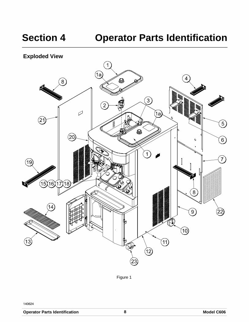
Exploded View
Figure 1

9Model C606 Operator Parts Identification
140624
Exploded View (See Figure 1)
ITEM DESCRIPTION PART NO.
1 KIT A.-COVER-HOPPER X65368-SP
1a LABEL-CAUTION-AGITATOR 045191
2 AGITATOR A.-MIX HOPPER-20 X44797
3 PIN-RETAINING HOPPER CVR 043934
4 PAN-DRIP-REAR X56003
5 PANEL-REAR-UPPER 066724
6 GUIDE A.-DRIP PAN-MIX PUMP X48228
7 PANEL-REAR-LOWER 055959
8 PAN-DRIP-SIDE X56005
9TRIM-CORNER-REAR-R 056692
TRIM-CORNER-REAR-L 056693
10 CASTER-4" 044106
11 SCREW-1/4-20X3/8 011694
ITEM DESCRIPTION PART NO.
12 PANEL-SIDE RIGHT 055950
13 TRAY-DRIP 033812
14 SHIELD-SPLASH 033813
15 LID-SYRUP JAR 042706
16 JAR-SYRUP*PLASTIC 036573
17 JAR-SYRUP*STAINLESS 036574
18 LADLE-1 OZ 033637-1
19 PAN-DRIP 19-1/2 LONG 035034
20 PLATE-DEC 056131-1
21 PANEL-SIDE LEFT 055957
22 FILTER-AIR-18.00LX13.50HX.70 052779-3
23 CASTER-4" SWV 3/4-10 STEMW/BRAKE
046437

10 Model C606Operator Parts Identification
140624
Front View
Figure 2
11Model C606 Operator Parts Identification
140624
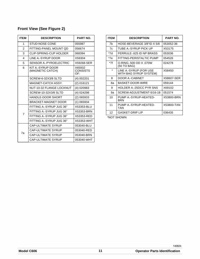
Front View (See Figure 2)
ITEM DESCRIPTION PART NO.
1 STUD-NOSE CONE 055987
2 FITTING-PANEL MOUNT QD 056674
3 CLIP-SPRING-CUP HOLDER 068394
4 LINE A.-SYRUP DOOR X59304
5 SENSOR A.-PYROELECTRIC X59268-SER
6 KIT A.-SYRUP DOOR(MAGNETIC CATCH)
X65932CONSISTSOF:
SCREW-6-32X3/8 SLTD (4) 002201
MAGNET-CATCH ASSY. (2) 016121
NUT-10-32 FLANGE LOCKNUT (4) 020983
SCREW-10-32X3/8 SLTD (4) 024298
HANDLE-DOOR SHORT (2) 065933
BRACKET-MAGNET DOOR (1) 065934
7
FITTING A.-SYRUP JUG 36" X53353-BLU
FITTING A.-SYRUP JUG 36" X53353-BRN
FITTING A.-SYRUP JUG 36" X53353-RED
FITTING A.-SYRUP JUG 36" X53353-WHT
7a
CAP-ULTIMATE SYRUP 053040-BLU
CAP-ULTIMATE SYRUP 053040-RED
CAP-ULTIMATE SYRUP 053040-BRN
CAP-ULTIMATE SYRUP 053040-WHT
ITEM DESCRIPTION PART NO.
7b HOSE-BEVERAGE 3/8"ID X 5/8 053052-36
7c TUBE A.-SYRUP PICK UP X53175
*7d FERRULE-.625 ID NP BRASS 053036
*7e FITTING-PERISTALTIC PUMP 054526
*7f O-RING-.500 OD X .070W(50 TO BAG)
024278
* LINE A.-SYRUP (FOR USEWITH BAG SYRUP SYSTEM)
X58450
8 DOOR A.-CABINET X58607-SER
8a BASKET-DOOR-WIRE 059144
9 HOLDER A.-25DCC PYR SNS X69102
9a SCREW-ADJUSTMENT-5/16-18 051574
10 PUMP A.-SYRUP-HEATED-BRN
X53800-BRN
11 PUMP A.-SYRUP-HEATED-TAN
X53800-TAN
12 GASKET-DRIP LIP 036435
*NOT SHOWN

12 Model C606Operator Parts Identification
140624
Syrup Cabinet View
Figure 3
ITEM DESCRIPTION PART NO.
1 SHELF-SYRUP 056016
2 PUMP-PERISTALTIC 052916
3 MOTOR-GEAR 161 RPM/SHORT SHAFT
058725-SER
4 BASKET-DOOR-WIRE 059144
5 BLOCK-HINGE 058613
6 BLOCK-HINGE 058614
*7a MAGNET-CATCH ASSY. 016121
7b SCREW-4-40X3/8 SOCKET CAP 058317
ITEM DESCRIPTION PART NO.
7c WASHER-#4 EXT TOOTH LOCK 043075
7d SCREW-6-32X3/8 SLTD BIND 002201
7e BRACKET-MAGNET DOOR 065934
8 HANDLE-DOOR SHORT 065933
8a SCREW-10-32X3/8 SLTD TRUS 024298
9 NUT-10-32 FLANGE LOCKNUT 020983
10 SCREW-10-32X3/8 SLTD 006749
11 WASHER-#8 EXT TOOTH LOCK 000964
12 SCREW-8-32X1/4 SLTD ROUND 016540
*PRIOR TO S/N K4091994, USE 058630 LATCH-DOOR-MAGNETIC.

13Model C606 Operator Parts Identification
Syrup Pump & Tubes
Figure 4
ITEM DESCRIPTION PART NO.
1 PUMP-PERISTALTIC 052916
2
KIT A.-PERISTALTIC PUMPTUBE (1 TUBE KIT)
X54978
KIT A.-PERISTALTIC PUMPTUBE (4 TUBE KIT)
X54979
ITEM DESCRIPTION PART NO.
3 FERRULE- .625 ID 053036
4 FITTING-PERISTALTIC PUMP 054526
5 O-RING 1/2 OD x .070 024278
*6 LINE A.-SYRUP X62426-8
*NOT SHOWN

14 Model C606Operator Parts Identification
140624
X57028-XX Pump A. - Mix Simplified - Shake
Figure 5
ITEM DESCRIPTION PART NO.
1 - 7 PUMP ASSEMBLY - MIXSIMPLIFIED SHAKE
X57028-10
1 CYLINDER-PUMP HOPPERSHAKE
057944
2 PIN-RETAINING X55450
3 PISTON-PUMP-SIMPLIFIED 053526
4 O-RING-2-1/8 OD X .139W-#225 020051
*5 CAP-VALVE BODY SHAKE 056873-10
6 GASKET - SIMPLIFIED PUMPVALVE
053527
7 ADAPTOR - MIX INLET - SHAKEBLUE
054944
8 O-RING-11/16ODX.103W-RED(50 TO BAG)
016132
9 PIN-COTTER-HAIRPIN-1/8DIA 044731
ITEM DESCRIPTION PART NO.
10 SHAFT A.-DRIVE-MIXPUMP-HOPPER
X41947
10a CRANK-DRIVE-HOPPER MIXPUMP
039235
10b SHAFT-DRIVE-MIX PUMP-HOPPER
041948
10c O-RING-1-3/4 OD X .139W(25 TO BAG)
008904
10d O-RING 1/2 ID X .139W(25 TO BAG)
048632
11 CLIP-RETAINER-MIX PUMP 044641
12 TUBE A.-FEED TUBE-SHK X55973
13 RING-CHECK-FEED-TUBE 056524
14 SLEEVE A.-MIX PUMP X44761
*STANDARD CAP-VALVE BODY SHAFT IS -10.AVAILABLE IN OTHER SIZES

15Model C606 Operator Parts Identification
140624
X57029-XX Pump A. - Mix Simplified - Soft Serve
Figure 6
ITEM DESCRIPTION PART NO.
1 - 7 PUMP A.-MIX SIMPLIFIED S.S. X57029-12
1 CYLINDER-PUMP HOPPERSOFTSERVE
057943
2 PIN-RETAINING X55450
3 PISTON-PUMP-SIMPLIFIED 053526
4 O-RING-2-1/8 OD X .139W-#225 020051
5 CAP-VALVE BODY SS 056874-12
6 GASKET-SIMPLIFIED PUMPVALVE
053527
7 ADAPTOR-MIX INLET-SS-RED 054825
8 O-RING-11/16ODX.103W-RED 016132
9 PIN-COTTER-HAIRPIN-1/8DIA 044731
10 SHAFT A.-DRIVE-MIX PUMP-HOPPER
X41947
ITEM DESCRIPTION PART NO.
10a CRANK-DRIVE-HOPPER MIXPUMP
039235
10b SHAFT-DRIVE-MIX PUMP-HOPPER
041948
10c O-RING-1-3/4 OD X .139W 008904
10d O-RING 1/2 ID X .139W 048632
11 CLIP-RETAINER-MIX PUMP 044641
12 TUBE A.-FEED TUBE-SS X55974
13 RING-CHECK-FEED-TUBE 056524
14 SLEEVE A.-MIX PUMP *HT X44761
*NOTE: THE STANDARD PUMP IS X57029-12.OVERRUN CAN BE CHANGED HIGHER OR LOWERBY SUBSTITUTING THE VALVE BODY CAP. THEHIGHER THE (-) THE HIGHER THE OVERRUN.

16 Model C606Operator Parts Identification
X59304 Syrup Line Assembly - Thin Viscosity Syrup
Figure 7
ITEM DESCRIPTION PART NO.
1 FERRULE-.650 ID NP BRASS 029834
2 INSERT-QD-CPC-3/8 BARB 056675
3 O-RING-11MM ID X 2MM WGREEN (25 TO BAG)
053890
4 TUBE-NYLOBRADE 3/8IDX5/8 500038-9
5 FITTING-SYRUP ELBOW 056651
ITEM DESCRIPTION PART NO.
6 VALVE-CHECK-DUCKBILL 500598
7 FITTING-SYRUP NOSE .075SLOT
056649
8 O-RING-11MM ID X 2MM WGREEN
053890

17Model C606 Operator Parts Identification
X56652 Syrup Line Assembly - Thick Viscosity Shake Syrup (Optional)
Figure 8
ITEM DESCRIPTION PART NO.
1 FERRULE-.625 ID 053036
2 FITTING BARB 056675
3 O-RING 500205
4 HOSE-BEVERAGE 053052-9
5 FITTING-SYRUP ELBOW 056651
ITEM DESCRIPTION PART NO.
6 VALVE-CHECK DUCKBILL 500598
7 FITTING-SYRUP NOSE(LARGE SLOT)
056650
8 O-RING-11 MM GREEN(SYRUP HOLE PLUG)
053890
18 Model C606Operator Parts Identification
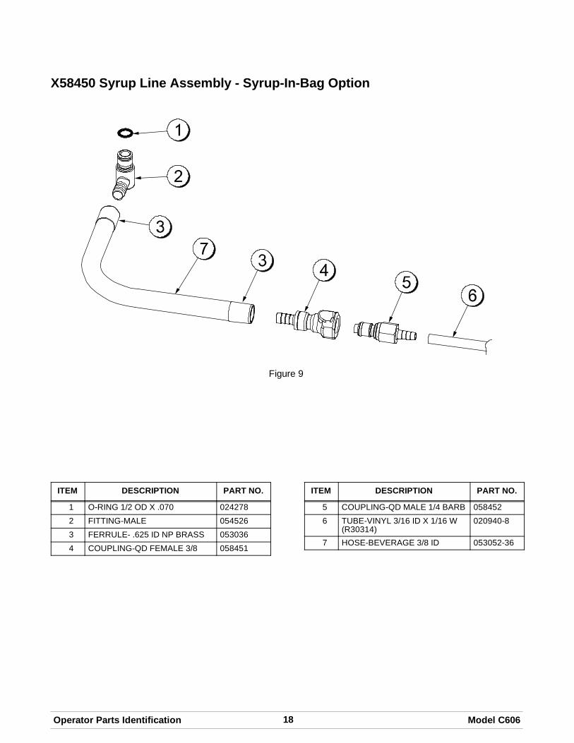
X58450 Syrup Line Assembly - Syrup-In-Bag Option
Figure 9
ITEM DESCRIPTION PART NO.
1 O-RING 1/2 OD X .070 024278
2 FITTING-MALE 054526
3 FERRULE- .625 ID NP BRASS 053036
4 COUPLING-QD FEMALE 3/8 058451
ITEM DESCRIPTION PART NO.
5 COUPLING-QD MALE 1/4 BARB 058452
6 TUBE-VINYL 3/16 ID X 1/16 W(R30314)
020940-8
7 HOSE-BEVERAGE 3/8 ID 053052-36

19Model C606 Operator Parts Identification
120522
Mix Hopper - Top View
Figure 10
ITEM DESCRIPTION PART NO.
1 SLEEVE A.-MIX PUMP X44761
2 PROBE A.MIX OUT X41348
3 HOUSING A.-AGITATOR(SHAKE)
X51664
3a4a
MAGNET A.-AGITATOR-INNER X41733
ITEM DESCRIPTION PART NO.
4 HOUSING A.-AGITATOR(SOFT SERVE)
X51661
5 PROBE A.-MIX LOW X42077
6 CAP-MAGNET 080826

20 Model C606Operator Parts Identification
140624
Accessories
Figure 11

21Model C606 Operator Parts Identification
140718
Accessories (See Figure 11)
ITEM DESCRIPTION PART NO.
1 KIT A.-SYRUP PLUG KIT TTS X58474
1a PLUG-SYRUP PORT TTS 053867
1b O-RING-11MM ID X 2MM WGREEN (25 TO BAG)
053890
1c TOOL-SEAL INSTALL-REMOVE 035460
2 O-RING-1-11/16 OD X.139W(25 TO BAG)(DRAW VALVE CAP)
041923
3 CAP A.-VALVE-DRAW X54704
4 LADLE-1 OZ-120D BEND 033637-1
5 CUP-DIVIDED SYRUP 017203
6 TOOL-O-RING REMOVAL 048260-WHT
7 LUBRICANT-TAYLOR HI PERF 048232
8 BOTTLE-WASH-PLASTIC 044818
9 TOOL-MIX PUMP SHAFTREMOVAL
057167
10 TRAY-PARTS-PUMP-SIMPL 056525
11 TRAY-PARTS-SHAKE SIDE 059088
ITEM DESCRIPTION PART NO.
12 TRAY-PARTS-SS SIDE 059087
13 PAIL-10 QT. 013163
14 DISPENSER A.-CUP-2 CONE X56121
14a BAFFLE-RUBBER CONE 052193
15 TRAY A.-SYRUP (OPTIONALSYRUP IN BAG SYSTEM)
X59143
16 TANK-SYRUP 4QT. PSD(OPTIONAL 4 TANK SYRUPSYSTEM)
056673
* KIT A.-PERISTALTIC PUMPTUBE
X54978
* KIT A.-TOPPING PUMPSPARES
X53795
* KIT A.-TUNE UP X49463-59
* DEFLECTOR-BLOWEREXHAUST
047912
* BOX-TOOL 15 INCH PLASTIC 058669
*NOT SHOWN
22 Model C606Operator Parts Identification
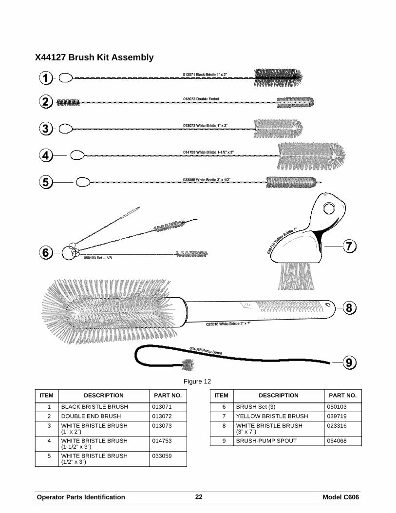
X44127 Brush Kit Assembly
Figure 12
ITEM DESCRIPTION PART NO.
1 BLACK BRISTLE BRUSH 013071
2 DOUBLE END BRUSH 013072
3 WHITE BRISTLE BRUSH(1” x 2”)
013073
4 WHITE BRISTLE BRUSH(1-1/2” x 3”)
014753
5 WHITE BRISTLE BRUSH(1/2” x 3”)
033059
ITEM DESCRIPTION PART NO.
6 BRUSH Set (3) 050103
7 YELLOW BRISTLE BRUSH 039719
8 WHITE BRISTLE BRUSH(3” x 7”)
023316
9 BRUSH-PUMP SPOUT 054068
23Model C606 Operator Parts Identification
140624
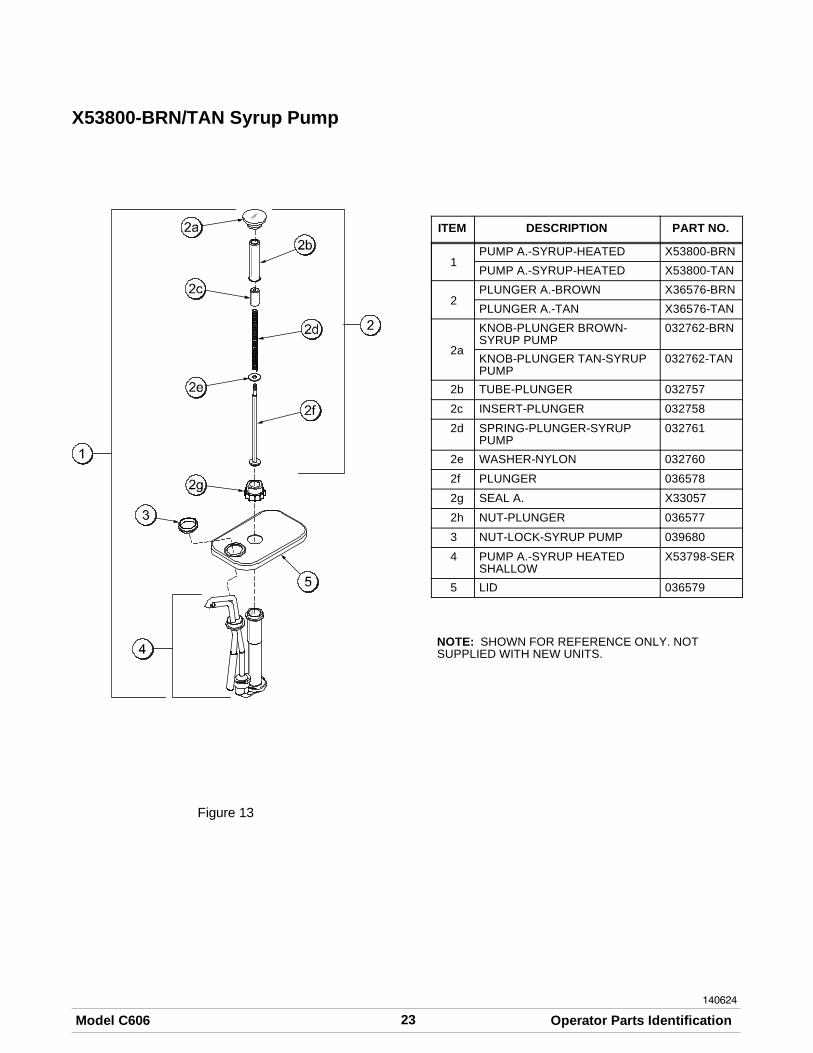
X53800-BRN/TAN Syrup Pump
Figure 13
ITEM DESCRIPTION PART NO.
1PUMP A.-SYRUP-HEATED X53800-BRN
PUMP A.-SYRUP-HEATED X53800-TAN
2PLUNGER A.-BROWN X36576-BRN
PLUNGER A.-TAN X36576-TAN
2a
KNOB-PLUNGER BROWN-SYRUP PUMP
032762-BRN
KNOB-PLUNGER TAN-SYRUPPUMP
032762-TAN
2b TUBE-PLUNGER 032757
2c INSERT-PLUNGER 032758
2d SPRING-PLUNGER-SYRUPPUMP
032761
2e WASHER-NYLON 032760
2f PLUNGER 036578
2g SEAL A. X33057
2h NUT-PLUNGER 036577
3 NUT-LOCK-SYRUP PUMP 039680
4 PUMP A.-SYRUP HEATEDSHALLOW
X53798-SER
5 LID 036579
NOTE: SHOWN FOR REFERENCE ONLY. NOTSUPPLIED WITH NEW UNITS.

24 Model C606Operator Parts Identification
Beater Door Assembly - Shake Side
Figure 14

25Model C606 Operator Parts Identification
Beater Door Assembly - Shake Side (See Figure 14)
ITEM DESCRIPTION PART NO.
1 SEAL-DRIVE SHAFT 032560
2 SHAFT-BEATER 7 QT. 050985
3 BLADE-SCRAPER 16” 041103
4 BEARING-DOOR FRONT 055605
5 BEATER A.-7 QT. FLUTEDBLADE
X50958
6 O-RING 6” (FREEZER DOOR) 033493
7 DOOR A.-SHAKE SIDE X55825SER2
8 NUT-STUD-SHORT 055989
9 O-RING SYRUP PORT 11 MM 053890
ITEM DESCRIPTION PART NO.
10 PLUG-SYRUP PORT 053867
11 RETAINER-SYRUP VALVE 054554
12 O-RING 1-1/16 OD X .139 W(DRAW VALVE)
020571
13 SEAL-SPINNER SHAFT 036053
14 SPINNER 034054
15 BLADE A.-SPINNER X59331
16 CAP-RESTRICTOR 033107
17 VALVE A.-DRAW 059000

26 Model C606Operator Parts Identification
140624
Beater Door Assembly - Soft Serve Side
Figure 15
ITEM DESCRIPTION PART NO.
1 HANDLE A.-DRAW X56421-1
2 NUT-STUD-BLACK-1.00 055989
3 DOOR A.-W/BAFFLE X57332-SER
3a BAFFLE A.-LONG 4 IN X50882
4 GASKET-DOOR HT 4"-DOUBLE 048926
5 KIT A.-BEATER-FRONTSHOES-BEARING
X50350
6 BEATER A.-3.4QT-1 PIN X46231
7 BLADE-SCRAPER-PLASTIC 046235
8 CLIP-SCRAPER BLADE 7 INCH 046236
ITEM DESCRIPTION PART NO.
9 SHAFT-BEATER 032564
10 SEAL-DRIVE SHAFT 032560
11 PIN-HANDLE-SS 055819
12 VALVE A.-DRAW X55820
13 O-RING-7/8 OD X .103W(100 TO BAG)
014402
14 O-RING-1/4 OD X .070W 50DURO (25 TO BAG)
015872
15 NUT-5/16-24 FINISHED HEX 029639-BLK
16 SCREW-ADJUSTMENT-5/16-24 056332

27Model C606 Operator Parts Identification
059088 Tray-Parts-Shake Side
Figure 16
ITEM DESCRIPTION PART NO.
1 BEATER A.-7 QT. X50958
2 BLADE-SCRAPER-16” 041103
3 SHAFT-BEATER 7 QT. 050985
4 SEAL-DRIVE SHAFT 032560
5 NUT-STUD 055989
6 O-RING -SYRUP PORT 11MMID GREEN
053890
7 PLUG-SYRUP PORT 053867
8 SPINNER 034054
9 BLADE A.-SPINNER X59331
10 SEAL-SPINNER SHAFT 036053
ITEM DESCRIPTION PART NO.
11 CAP-RESTRICTOR 033107
12 VALVE A.-DRAW X57169
13 VALVE-CHECK DUCKBILL 500598
14 BEARING-DOOR FRONT 055605
15 O-RING - 1-1/16 OD (DRAWVALVE)
020571
16 FITTING-SYRUP NOSE SEE PAGES16 & 17
17 RETAINER-SYRUP VALVE 054554
18 O-RING 6” - DOOR 033493
18 DOOR A.-SHAKE X55825SER2

28 Model C606Operator Parts Identification
059087 Tray-Parts-Soft Serve Side
Figure 17
ITEM DESCRIPTION PART NO.
1 HANDLE A.-DRAW X56421-1
2 PIN-PIVOT 055819
3 BEARING-FRONT 050348
4 NUT-STUD 055989
5 O-RING (DRAW VALVE) 014402
6 GASKET (FREEZER DOOR) 048926
7 VALVE A.-DRAW X55820
8 DOOR A.-W/BAFFLE X57332-SER
ITEM DESCRIPTION PART NO.
9 SHOE-FRONT HELIX- FRONT 050347
10 DRIVE SHAFT 032564
11 SEAL-DRVE SHAFT 032560
12 BLADE-SCRAPER 046235
13 CLIP-SCRAPER BLADE 046236
14 BEATER A. X46231
15 SHOE-FRONT HELIX- REAR 050346

29Model C606 Operator Parts Identification
050621
056525 Tray-Parts-Pump-Simplified
Figure 18
Shake Side
ITEM DESCRIPTION PART NO.
1 CLIP-MIX PUMP RETAINER 044641
2 CYLINDER-PUMP-HOPPERSHAKE
057944
3 PIN A.-RETAINING X55450
4 PISTON 053526
5 PIN-COTTER 044731
6 O-RING 2-1/8” OD - RED 020051
7 CAP-VALVE 056873-XX
8 GASKET-SIMPLIFIED PUMP 053527
9 ADAPTOR-MIX INLETSHAKE-BLUE
054944
10 RING-CHECK .120 OD 056524
11 SHAFT A.-DRIVE MIX PUMP X41947
12 O-RING-DRIVE SHAFT 048632
13 TUBE A.-FEED-HOPPERSHAKE
X55973
14 O-RING 1-3/4 008904
15 O-RING-11/16 OD - RED 016132
Soft Serve Side
ITEM DESCRIPTION PART NO.
1 CLIP-MIX PUMP RETAINER 044641
2 CYLINDER-PUMP-HOPPER-SOFT SERVE
057943
3 PIN A.-RETAINING X55450
4 PISTON 053526
5 PIN-COTTER 044731
6 O-RING 2-1/8” OD - RED 020051
7 CAP-VALVE 056874-XX
8 GASKET-SIMPLIFIED PUMP 053527
9 ADAPTOR-MIX INLET SOFTSERVE-RED
054825
10 RING-CHECK .120 OD 056524
11 SHAFT A.-DRIVE MIX PUMP X41947
12 O-RING-DRIVE SHAFT 048632
13 TUBE A.-FEED-HOPPERSOFT SERVE
X55974
14 O-RING 1-3/4 008904
15 O-RING-11/16 OD - RED 016132
16 AGITATOR A.-MIX HOPPER X44797
30 Model C606Important: To the Operator
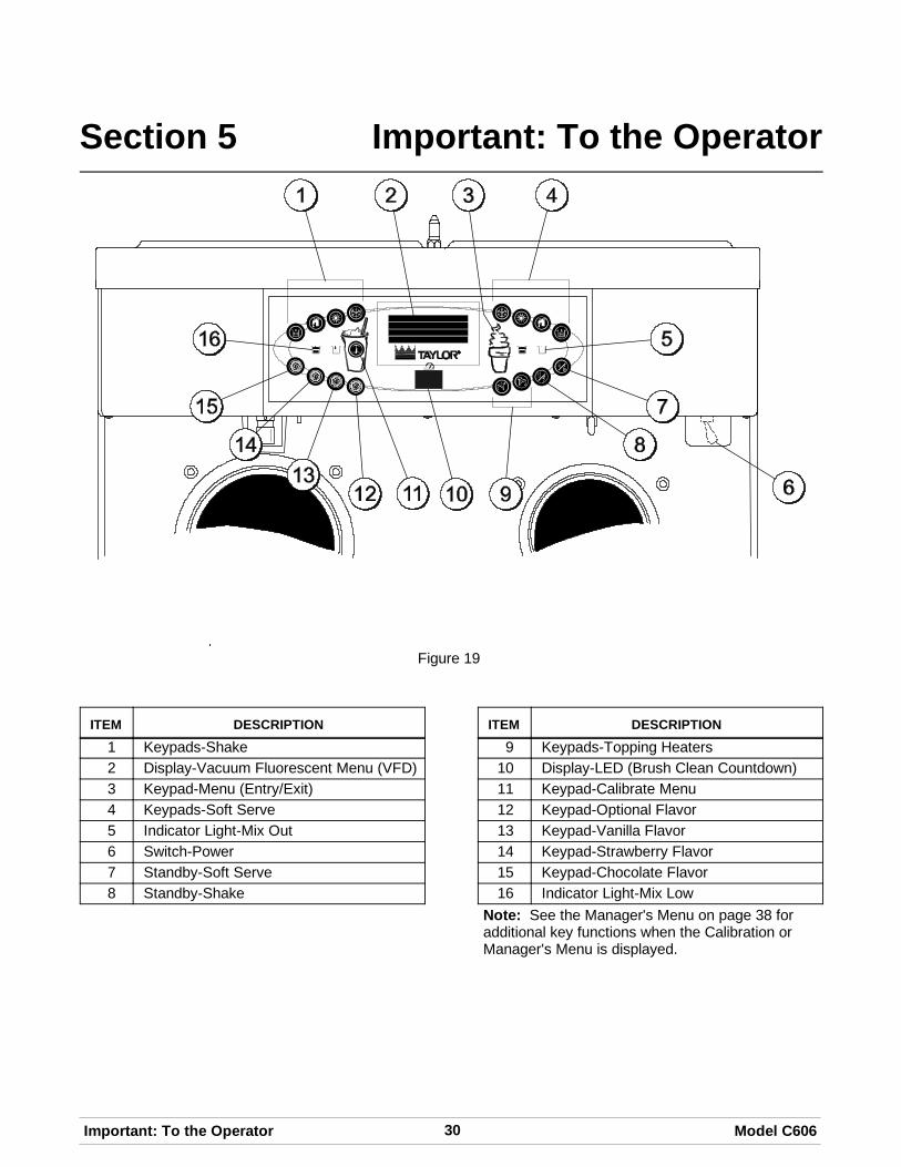
Section 5 Important: To the Operator
Figure 19
ITEM DESCRIPTION
1 Keypads-Shake
2 Display-Vacuum Fluorescent Menu (VFD)
3 Keypad-Menu (Entry/Exit)
4 Keypads-Soft Serve
5 Indicator Light-Mix Out
6 Switch-Power
7 Standby-Soft Serve
8 Standby-Shake
ITEM DESCRIPTION
9 Keypads-Topping Heaters
10 Display-LED (Brush Clean Countdown)
11 Keypad-Calibrate Menu
12 Keypad-Optional Flavor
13 Keypad-Vanilla Flavor
14 Keypad-Strawberry Flavor
15 Keypad-Chocolate Flavor
16 Indicator Light-Mix Low
Note: See the Manager's Menu on page 38 foradditional key functions when the Calibration orManager's Menu is displayed.

31Model C606 Important: To the Operator
Symbol Definitions
To better communicate in the International arena,symbols have replaced words on many of ouroperator switches, function, and fault indicators.Your Taylor equipment is designed with theseInternational symbols.
The following chart identifies the symbol definitions.
= AUTO
= HEAT CYCLE
= WASH
= MIX PUMP
= STANDBY (SHAKE)
= STANDBY (SOFT SERVE)
= FLAVOR SELECTION
= MIX LOW
= MIX OUT
= TOPPING HEATER-LEFT
= TOPPING HEATER-RIGHT
= CALIBRATE
= MENU DISPLAY
Power Switch
When placed in the ON position, the power switchallows control panel operation.
Vacuum Fluorescent Display
The vacuum fluorescent display (VFD) is located onthe front control panel. During normal operation thedisplay is blank. The display is used to show menuoptions and notifies the operator if a fault isdetected. The display will indicate the temperature ofthe mix in each hopper.
Indicator Lights
MIX LOW - When the MIX LOW symbol isilluminated, the mix hopper has a low supply of mixand should be refilled as soon as possible.
MIX OUT - When the MIX OUT symbol isilluminated, the mix hopper has been almostcompletely exhausted and has an insufficient supplyof mix to operate the freezer. At this time, the AUTOmode is locked out and the freezer will be placed inthe STANDBY mode. To initiate the refrigerationsystem, add mix to the mix hopper and touch the
AUTO symbol . The freezer will automaticallybegin operation.

32 Model C606Important: To the Operator
091002
Heat Mode Symbol
When the HEAT MODE symbol is illuminated,the freezer is in the process of a heat cycle. Theheat mode symbol may be selected to start a heatcycle following a freezer soft lock condition.
For some models, the heat symbol can be selectedto manually start a heat cycle at any time.
Brush Clean Countdown - Displays the number ofdays before the next brush cleaning is required.When the display has counted down to “1”, themachine must be disassembled and brush cleanedwithin 24 hours.
Reset Mechanism
The reset button is located in the service panel atthe rear of the machine. (See Figure 20.) It protectsthe beater motor from an overload condition. Shouldan overload occur, the reset mechanism will trip. Toproperly reset the freezer place the power switch inthe OFF position. Press the reset button firmly. Turnthe power switch to the ON position. Touch the
WASH symbol and observe the freezer'sperformance. (See Figure 20.)
Figure 20
WARNING: Do not use metal objects topress the reset button. Failure to comply mayresult in severe personal injury or death.
If the beater motor is turning properly, touch the
WASH symbol to cancel the cycle. Touch the
AUTO symbol to resume normal operation. If thefreezer shuts down again, contact your authorizedservice technician.
Air/Mix Pump Reset Mechanism
The reset button for the pump is located in theservice panel at the rear of the machine. (SeeFigure 20.) The reset protects the pump from anoverload condition. Should an overload occur, thereset mechanism will trip. To reset the pump, pressthe reset button firmly.
WARNING: Do not use metal objects topress the reset button. Failure to comply mayresult in severe personal injury or death.
Adjustable Draw Handle
This unit features an adjustable draw handle toprovide the best portion control, giving a better,consistent quality to your product and controllingcosts. The draw handle should be adjusted toprovide a flow rate of 5 to 7-1/2 oz. (142 to 213 g.)of product by weight per 10 seconds. To INCREASEthe flow rate, tighten the screw. To DECREASE theflow rate, loosen the screw. After setting the flowrate, tighten the jam nut to secure the adjustmentscrew. (See Figure 21.)
Figure 21

33Model C606 Important: To the Operator
120515
Shake Fill Level Adjustment
The portion control sensor located under the cupholder can be adjusted to fill the cup to the desiredlevel. If the fill level is too low, or the cup isoverfilling, it may be necessary to adjust the sensorposition. (See Figure 22.)
Figure 22
Step 1Using a crescent wrench, loosen the locking nut onthe screw adjuster below the sensor.
Step 2Turn the adjustment screw clockwise to raise the filllevel, or counterclockwise to lower the fill level.
Step 3Once the desired fill level is achieved, tighten thelocking nut.
VFD Screens
The vacuum fluorescent display (VFD) located in thecenter of the control panel is normally blank duringthe daily operation of the machine. The display is
activated when the CALIBRATE symbol or theManager's Menu is selected. The display screen willalso alert the operator of specific faults detected bythe control.
Power Up
When the machine is powered, the control systemwill initialize to perform a system check. There willfour types of data that the system will check whenthe control is initializing: Lamp Test, Lockout Data,Configuration Data, and System Data.(See Figure 23.)
C602 / C606 UVC4V01.01.000lamptest
Figure 23
Lamp Test: The control and software version isdisplayed and all of the LED's on the display panelare illuminated. (See Figure 24.)
Initializing . . . . .
Figure 24
Following the lamp test, three separate screens willappear during initialization.
Initializing . . . . Lockout Data
Initializing . . . . Config Data
Initializing . . . . System Data
If the system detects corrupt data during theINITIALIZING, the following display will alert theoperator that the control settings have changed(See Figure 25.)
SERVICE REQ'DNVRAM FAULTRESET TO DEFAULTS< Press to clear
Figure 25

34 Model C606Important: To the Operator
120515
Once the system has initialized, the number of daysremaining before the next required brush cleaning isindicated on the control panel and the SAFETYTIMEOUT screen is displayed with the alarm turnedon. (See Figure 26.)
SAFETY TIMEOUTANY KEY ABORTS
Figure 26
The SAFETY TIMEOUT screen will be displayedwith the alarm on, for 60 seconds or until any controlsymbol is selected.
After the safety timeout has been completed and thepower switch is OFF, the status screen will display.When the brush clean requirements have been met,the following screen will display. (See Figure 27.)
POWER SWITCH OFF- = - = - = - = - = -UNIT CLEANED
Figure 27
If a brush cleaning was not completed, the statusscreen will display the current hopper temperature,barrel temperature, and the five minute brush cleantimer. (See Figure 28.)
POWER SWITCH OFFTIME: 5:0041.0 HOPPER 41.041.0 BARREL 41.0
Figure 28
Power Switch ON
When the power switch is placed in the ON position,the control panel touch keys become operative. TheVFD will be either blank or indicate that the unit hasbeen cleaned. (See Figure 29.)
UNIT CLEANED
Figure 29
Some models will continuously display thetemperature of each mix hopper when the powerswitch is in the ON position. (See Figure 30.)
HOPPERS 21.0 21.1
UNIT CLEANED
Figure 30
Heat Cycle
The HEAT symbols on the control panel areilluminated throughout the heat treatment cycle. Twowarning messages will be displayed on the screen.“DO NOT DRAW” will be displayed when the mixtemperature is below 130°F (54.4°C).(See Figure 31.)
L: DO NOT DRAWR: DO NOT DRAW
Figure 31

35Model C606 Important: To the Operator
When the temperature of the mix is above 130°F(54.4°C) the screen will display a messageindicating that HOT PRODUCT is in the machine.(See Figure 32.)
L: HOT PRODUCTR: HOT PRODUCT
Figure 32
DO NOT attempt to draw product ordisassemble the unit during the HEAT cycle. Theproduct is hot and under extreme pressure.
In the HEAT cycle, the mix temperature in thehoppers and freezing cylinders must be raised to151°F (66.1°C) within 90 minutes.
When the heating phase is complete, the freezergoes into the holding phase of the cycle. The holdingphase will keep the temperature above 151°F(66.1°C) for a minimum of 30 minutes.
The final phase of the heat treatment cycle is thecooling phase. The freezer must cool the mix below41°F (5°C) within two hours.
When the entire heat cycle has been completed, the
HEAT symbols will no longer be illuminated. Themachine will enter the STANDBY mode (STANDBY
symbols and illuminate). The machine can beplaced in AUTO or left in STANDBY.
Heat Cycle Failure Messages
To comply with health codes, heat treatment systemfreezers must complete a heat treatment cycledaily, and must be disassembled and brush cleaneda minimum of every 14 days. Brush cleaning is thenormal disassembly and cleaning procedure found inthis manual. Failure to follow these guidelines willcause the control to lock the freezer out of theAUTO mode.
Always comply with local guidelines for themaximum number of days allowed between brushclean cycles. (See the Manager's Menu for settingthe Brush Clean interval, on page 44.)
If the Heat Treatment Cycle fails, the VFD willdisplay a failure message and return the freezer tothe STANDBY mode. A “lock” is defined as a specialSTANDBY mode of operation which does not allowthe machine to operate in the AUTO mode.
There are two types of freezer lock conditions thatcan occur: Hard Lock or Soft Lock. A Hard Lockrequires the machine be disassembled and brushcleaned. A Soft Lock can be corrected by eitherdisassembling and brush cleaning the machine, orby starting another heat treatment cycle.
Hard Lock: There are two causes of a hard lockfailure:
1. The brush clean timer has elapsed (maximumsetting of 14 days). (See Figure 33.)
BRUSH CLEAN TIMEOUTFREEZER LOCKEDCLEANING REQ'D
WASH TO BRUSH CLEAN
Figure 33
Selecting the WASH symbol will display thefollowing screen. (See Figure 34.)
FREEZER LOCKED
Figure 34
2. There has been a thermistor failure (freezingcylinder, hopper, or glycol) during the heattreatment process. (See Figure 35.)
SYSTEM FAULTFREEZER LOCKED
SERVICE REQ'D< PRESS TO CLEAR
Figure 35

36 Model C606Important: To the Operator
Selecting the CALIBRATE symbol will indicatewhich thermistor caused the Hard Lock.(See Figure 36.)
L: HOPPER THERM BAD
FREEZER LOCKED
Figure 36
If the machine has hard locked and an attempt ismade to enter AUTO, the machine will enter theSTANDBY mode and display the following message.(See Figure 37.)
FREEZER LOCKED
Figure 37
To restore the message that identified the reason forthe hard lock, turn the power switch OFF for fiveseconds and then return the power switch to the ONposition. The original message with the reason forthe Hard Lock will be displayed. The FAULTDESCRIPTION can also be found in the Manager'sMenu (See page 44.)
The FREEZER LOCKED message will remain onthe display until the brush clean requirements arefulfilled. The freezer must be disassembled in orderto activate the five minute timer on the displayscreen. Once the timer counts down to zero, thelockout is cleared.
Soft Lock: If a heat treatment cycle has not beeninitiated within the last 24 hours, a soft lock failurewill occur. A soft lock allows the operator to correctthe cause of the soft lock. The operator has theoption of either starting another heat cycle or brushcleaning the machine.
When a soft lock occurs, the machine will go into theSTANDBY mode. The following message isdisplayed on the screen. The reason for the soft lockis indicated on the second line. (See Figure 38.)
HEAT TREAT FAILUREREASON
HEAT FOR HEAT CYCLEWASH TO BRUSH CLEAN
Figure 38
If the reason for the soft lock has been corrected,
selecting the HEAT symbol initiates a Heat Cycle
immediately. Selecting the WASH symbol whenthe above message is displayed will hard lock themachine and brush cleaning will be necessary.
Following are the variable messages for soft lockfailures that appear on the second line of the screen.
POWER SWITCH OFF Power switch was in theOFF position.
MIX OUT PRESENT There was a mix outcondition present.
AUTO OR STANDBYOFF
The machine was not inthe AUTO or STANDBYmode.
NO HEAT CYCLETRIED
A heat treatment cyclewas not attempted inthe last 24 hours.(AUTO HEAT TIMEwas advanced,a powerloss was experienced atthe time the cycle wasto occur, or a heat cyclefailure not due to athermistor failure.)

37Model C606 Important: To the Operator
120515
If the following screen appears, a soft lock hasoccurred during the heat treatment cycle.(See Figure 39.)
HEAT TREAT FAILUREFREEZER LOCKEDHEAT FOR HEAT CYCLEWASH TO BRUSH CLEAN
Figure 39
A soft lock can also occur any time during operationwhen the hopper or freezing cylinder temperaturerises above 59_F (15_C), rises and remains above45_F(7_C) for more than one hour, or rises andremains above 41_F(5_C) for more than four hours.If a PRODUCT OVER TEMPERATURE conditionoccurs during operation, the following screen willappear. (See Figure 40.)
PRODUCT OVER TEMP
HEAT FOR HEAT CYCLEWASH TO BRUSH CLEAN
Figure 40
When one of these messages appears, automaticfreezer operation cannot take place until the freezeris disassembled and brush cleaned, or hascompleted a heat treatment cycle. Select the HEAT
symbol to start a heat cycle, or select the WASH
symbol to disassemble and brush clean themachine.
Once the freezer is unlocked by starting a heat
treatment cycle the HEAT symbol will illuminateand the following message will be displayed on thescreen. (See Figure 41.)
L: DO NOT DRAWR: DO NOT DRAW
Figure 41
If the WASH symbol is selected to clear thelockout by brush cleaning the machine, theFREEZER LOCKED message will remain on thedisplay until the brush clean requirements arefulfilled. The freezer must be disassembled in orderto activate the five minute timer on the displayscreen. Once the timer counts down to zero, thelockout is cleared. (See Figure 42.)
FREEZER LOCKED
Figure 42
To restore the message that identified the reason forthe soft lock, turn the power switch OFF for fiveseconds, and then return the power switch to theON position. The original message with the reasonfor the soft lock will be displayed. (See Figure 43.)
HEAT TREAT FAILUREREASON
HEAT FOR HEAT CYCLEWASH TO BRUSH CLEAN
Figure 43
The FAULT DESCRIPTION can also be found in theManager's Menu. (See page 44.)
Note: A record of Heat Cycle Data and Lock OutHistory can be found in the Manager's Menu. (Seepage 47.)
38 Model C606Important: To the Operator
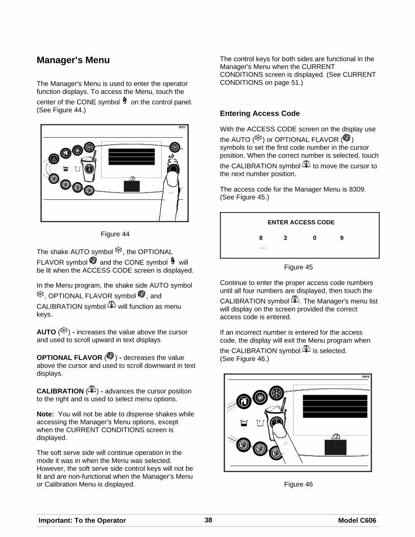
Manager's Menu
The Manager's Menu is used to enter the operatorfunction displays. To access the Menu, touch the
center of the CONE symbol on the control panel.(See Figure 44.)
Figure 44
The shake AUTO symbol , the OPTIONAL
FLAVOR symbol and the CONE symbol willbe lit when the ACCESS CODE screen is displayed.
In the Menu program, the shake side AUTO symbol
, OPTIONAL FLAVOR symbol , and
CALIBRATION symbol will function as menukeys.
AUTO ( ) - increases the value above the cursorand used to scroll upward in text displays
OPTIONAL FLAVOR ( ) - decreases the valueabove the cursor and used to scroll downward in textdisplays.
CALIBRATION ( ) - advances the cursor positionto the right and is used to select menu options.
Note: You will not be able to dispense shakes whileaccessing the Manager's Menu options, exceptwhen the CURRENT CONDITIONS screen isdisplayed.
The soft serve side will continue operation in themode it was in when the Menu was selected.However, the soft serve side control keys will not belit and are non-functional when the Manager's Menuor Calibration Menu is displayed.
The control keys for both sides are functional in theManager's Menu when the CURRENTCONDITIONS screen is displayed. (See CURRENTCONDITIONS on page 51.)
Entering Access Code
With the ACCESS CODE screen on the display use
the AUTO ( ) or OPTIONAL FLAVOR ( )symbols to set the first code number in the cursorposition. When the correct number is selected, touch
the CALIBRATION symbol to move the cursor tothe next number position.
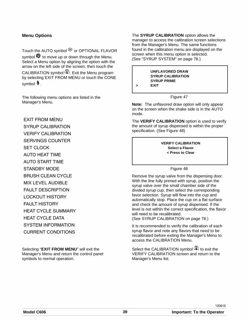
The access code for the Manager Menu is 8309.(See Figure 45.)
ENTER ACCESS CODE
8 3 0 9__
Figure 45
Continue to enter the proper access code numbersuntil all four numbers are displayed, then touch the
CALIBRATION symbol . The Manager's menu listwill display on the screen provided the correctaccess code is entered.
If an incorrect number is entered for the accesscode, the display will exit the Menu program when
the CALIBRATION symbol is selected.(See Figure 46.)
Figure 46
39Model C606 Important: To the Operator
120515
Menu Options
Touch the AUTO symbol or OPTIONAL FLAVOR
symbol to move up or down through the Menu.Select a Menu option by aligning the option with thearrow on the left side of the screen, then touch the
CALIBRATION symbol . Exit the Menu programby selecting EXIT FROM MENU or touch the CONE
symbol .
The following menu options are listed in theManager's Menu.
EXIT FROM MENU
SYRUP CALIBRATION
VERIFY CALIBRATION
SERVINGS COUNTER
SET CLOCK
AUTO HEAT TIME
AUTO START TIME
STANDBY MODE
BRUSH CLEAN CYCLE
MIX LEVEL AUDIBLE
FAULT DESCRIPTION
LOCKOUT HISTORY
FAULT HISTORY
HEAT CYCLE SUMMARY
HEAT CYCLE DATA
SYSTEM INFORMATION
CURRENT CONDITIONS
Selecting “EXIT FROM MENU” will exit theManager's Menu and return the control panelsymbols to normal operation.
The SYRUP CALIBRATION option allows themanager to access the calibration screen selectionsfrom the Manager's Menu. The same functionsfound in the calibration menu are displayed on thescreen when this menu option is selected.(See “SYRUP SYSTEM” on page 78.)
UNFLAVORED DRAWSYRUP CALIBRATIONSYRUP PRIME
> EXIT
Figure 47
Note: The unflavored draw option will only appearon the screen when the shake side is in the AUTOmode.
The VERIFY CALIBRATION option is used to verifythe amount of syrup dispensed is within the properspecification. (See Figure 48)
VERIFY CALIBRATIONSelect a Flavor< Press to Clear
Figure 48
Remove the syrup valve from the dispensing door.With the line fully primed with syrup, position thesyrup valve over the small chamber side of thedivided syrup cup, then select the correspondingfavor selection. Syrup will flow into the cup andautomatically stop. Place the cup on a flat surfaceand check the amount of syrup dispensed. If thelevel is not within the correct specification, the flavorwill need to be recalibrated.(See SYRUP CALIBRATION on page 78.)
It is recommended to verify the calibration of eachsyrup flavor and note any flavors that need to berecalibrated before exiting the Manager's Menu toaccess the CALIBRATION Menu.
Select the CALIBRATION symbol to exit theVERIFY CALIBRATION screen and return to theManager's Menu list.

40 Model C606Important: To the Operator
120515
The SERVINGS COUNTER screen is used to checkor reset the number of servings dispensed from themachine. (See Figure 49.)
SERVINGS COUNTERL = 0 R = 0Next
> Exit
Figure 49
Reset the SERVINGS COUNTER by selecting the
AUTO symbol to move the arrow (>) to “Next”.The Reset Counters and Details selections will bedisplayed on the next screen. (See Figure 50.)
SERVINGS COUNTERDetails
> Reset CountersExit
Figure 50
Select the AUTO symbol to move the arrow toRESET COUNTERS. Then select the
CALIBRATION symbol . (See Figure 51.)
SERVINGS COUNTERAre you sure?
> YesNo
Figure 51
The display will ask, “Are you sure?” To reset the
counters, select the AUTO symbol to move the
arrow to YES. Select the CALIBRATION symbolto clear the left and right counters and return to theSERVINGS COUNTER screen. If you do not want toclear the serving counter, move the arrow to “No”
and select the CALIBRATION symbol to returnto the SERVINGS COUNTER screen withoutresetting the counters to zero.
Note: The SERVINGS COUNTER will automaticallyreset to zero when the machine is brush cleaned.(See Figure 52.)
SERVINGS COUNTERL = 0 R = 0Next
> Exit
Figure 52
Access the Details screen by selecting “Next” in theSERVINGS COUNTER screen. Move the arrow to“Details” and then select the CALIBRATION symbol
. (See Figure 53.)
SERVINGS COUNTER> Details
Reset CountersExit
Figure 53
The counter menu will also display details for thenumber of servings for each flavor (chocolate,strawberry, vanilla, option, unflavored, and softserve), and count the method that ended the drawfor each flavor (pyroelectric sensor detection,manually selecting a flavor key, draw safety timeout,and other). (See Figure 54.)
Example:
CHOCOLATEPyro = 0 Oper = 0Time = 0 Other = 0
> Next
Figure 54
Pyro = Pyrosensor detected and triggered the endof the draw.
Time = The Draw Safety Time setting was reachedbefore the pyrosensor detection or before a flavorkey was selected.
Oper = A flavor key was selected to terminate thedraw.
Other = Any draw termination that is not Pyro, Time,or Oper (example: power switch turned off whileproduct is dispensing)

41Model C606 Important: To the Operator
120515
The SET CLOCK option allows the Manager toadjust the control clock date and time. The date andtime may only be changed after the freezer hasbeen manually cleaned but before it has beenplaced in the AUTO or STANDBY mode. Thefollowing message will be displayed if the SETCLOCK option is selected when the machine is notin a brush clean state. (See Figure 55.)
SET CLOCK08:00 05/15/2012NO CHANGES ALLOWEDPress Any Key
Figure 55
To change the date or time, select the SET CLOCK
option in the menu. Touch the AUTO symbol toadvance the arrow from Exit to Change, then touch
the CALIBRATION symbol to select the Changeoption. (See Figure 56.)
SET CLOCK08:00 05/15/2012
Change> Exit
Figure 56
Change the time by touching the AUTO or
OPTIONAL FLAVOR symbol with the cursorunder the hour position. Move the cursor to the
minutes by selecting the CALIBRATION symbol .Once the correct minutes are entered, select the
CALIBRATION symbol to advance the cursor tothe month. (See Figure 57.)
SET CLOCK08:00 05/15/2012
> Exit
Figure 57
Enter the correct month, day, and year. Then select
the CALIBRATION symbol to advance to theDAYLIGHT SAVING TIME screen. (See Figure 58.)
DAYLIGHT SAVING TIMEENABLED
> EnableDisable
Figure 58
To Disable the Daylight Saving Time feature, select
the AUTO symbol to move the arrow to “Disable”.
Touch the CALIBRATION symbol to save theselection.
To enable the Daylight Saving Time feature, select
the AUTO symbol to move the arrow to “Enable”.
Touch the CALIBRATION symbol to save theselection.
The Daylight Saving Time feature, when enabled,will automatically adjust the control clock for DaylightSaving Time. Change the month and week forDaylight Savings Time by selecting the AUTO
symbol to advance the arrow from “Exit” to
“Change”. Touch the CALIBRATION symbol toselect the Change option and move to the nextscreen. (See Figure 59.)
MAR SECOND SUNDAYNOV FIRST SUNDAYChange
> Exit
Figure 59
Use the arrow keys to scroll to the appropriate
month. Touch the CALIBRATION symbol toaccept the selection. (See Figure 60.)
DST START MONTHJANFEB
> MAR
Figure 60

42 Model C606Important: To the Operator
120515
Once the appropriate month has been entered,scroll to the appropriate week. Touch the
CALIBRATION symbol to accept the selection.(See Figure 61.)
DST START WEEKFIRST SUNDAY
> SECOND SUNDAYTHIRD SUNDAY
Figure 61
Note: Scroll down to see selections “FOURTHSUNDAY” and “LAST SUNDAY”.
Select the month that Daylight Saving Time will end.
Touch the CALIBRATION symbol to accept theselection. (See Figure 62.)
DST END MONTH> NOV
DECJAN
Figure 62
Select the appropriate week that Daylight Saving
Time will end. Touch the CALIBRATION symbolto accept the selection. (See Figure 63.)
DST END WEEK> FIRST SUNDAY
SECOND SUNDAYTHIRD SUNDAY
Figure 63
Select the CALIBRATION symbol to exit thescreen and return to the Menu.
The AUTO HEAT TIME screen allows the Managerto set the time of day in which the heat treatmentcycle will start. (See Figure 64.)
AUTO HEAT TIME00:00
Change> Exit
Figure 64
Note: Do not advance the Auto Heat Time settingexcept on the day the unit is brush cleaned.Increasing the time between heat cycles will causethe machine to soft lock if the start of the cycle doesnot begin within 24 hours from the start of theprevious heat treatment cycle.
To set the AUTO HEAT TIME select the AUTO
symbol to move the arrow to Change. Then
select the CALIBRATION symbol . The screenwill display the time with the cursor under the hourposition. (See Figure 65.)
AUTO HEAT TIME00:00
Figure 65
Select the AUTO symbol or the OPTIONAL
FLAVOR symbol to increase or decrease thehour to the desired setting. Then move the cursor tothe minutes position by selecting the CALIBRATION
symbol . Adjust the setting for minutes, then
select the CALIBRATION symbol to save thesetting and return to the AUTO HEAT TIME screen.
Select the CALIBRATION symbol to exit thescreen and return to the Menu.

43Model C606 Important: To the Operator
120515
The AUTO START TIME option allows the Managerto set the time of day at which the machineautomatically enters the AUTO mode from theSTANDBY mode. The machine must be in theSTANDBY mode without a freezer lock condition inorder to AUTO start at the programmable time. TheAUTO START TIME can also be Disabled andrequire starting the AUTO mode manually. (SeeFigure 66.)
AUTO START TIMEDISABLED
Enable> Disable
Figure 66
Enable the AUTO START TIME by selecting the
AUTO symbol to move the arrow up to Enable.
Select the CALIBRATION symbol to advance tothe next screen. (See Figure 67.)
AUTO START TIME00:00
Change> Exit
Figure 67
Program the AUTO START TIME by selecting the
AUTO symbol to move the arrow to Change.
Select the CALIBRATION symbol to advance tothe next screen. (See Figure 68.)
AUTO START TIME00:00
Figure 68
Program the AUTO START TIME by increasing
(AUTO symbol ) or decreasing (OPTIONAL
FLAVOR symbol ) the hour setting above the
cursor. Select the CALIBRATION symbol toadvance the cursor and program the minutessetting.
Select the CALIBRATION symbol to return to theprevious screen with the new time setting displayed.
Select the CALIBRATION symbol to exit thescreen and return to the Menu.
The STANDBY MODE option is used only onmodels which have the control panel Standby keysdisabled.
The STANDBY option is used to manually place theleft or right side in the standby mode during long, nodraw periods. Select the STANDBY screen from the
Menu. Select the AUTO symbol to move thearrow up to the left (shake) or right (soft serve) side.
Select the CALIBRATION symbol to activateStandby for the selected side.
Repeat the steps to activate Standby on theremaining side. (See Figure 69.)
STANDBY MODELEFTRIGHT
> EXIT
Figure 69
Discontinue Standby operation for either side byexiting the Manager's Menu and select the AUTOmode.
The BRUSH CLEAN CYCLE option allows theManager to select the maximum number of daysbetween brush cleaning the machine. The brushclean cycle may only be changed after the freezerhas been manually cleaned but before it has beenplaced in the AUTO or STANDBY mode.
The following message will be displayed if theBRUSH CLEAN CYCLE option is selected when themachine is not in a brush clean state.(See Figure 70.)
BRUSH CLEAN CYCLETIME 14 DAYSNo Changes AllowedPress any Key
Figure 70

44 Model C606Important: To the Operator
120515
Change the number of days between brush clean
intervals by selecting the AUTO symbol todecrease the days or the OPTIONAL FLAVOR
symbol to increase the number of days. Select
the CALIBRATION symbol to save the settingand exit back to the Menu. The number of daysdisplayed on the brush clean counter will change tothe new setting. (See Figure 71.)
BRUSH CLEAN CYCLETIME 14 DAYS
Figure 71
Always comply with local guidelines on the numberof days allowed between brush clean cycles.
The MIX LEVEL AUDIBLE option, when enabled,will alert the operator with an audible tone whenthere is mix low or mix out condition. The followingscreen is displayed upon selecting this option.(See Figure 72.)
MIX LEVEL AUDIBLEENABLED
> EnableDisable
Figure 72
Disable the audible tone feature by selecting the
AUTO symbol to move the arrow to DISABLE.
Select the CALIBRATION symbol to save thenew setting and return to the Menu. The controlpanel icons for Mix Low and Mix Out will light as themix level drops in the hopper but the audible tonewill be disabled.
The FAULT DESCRIPTION display will indicate ifthere is a fault with the freezer and the side offreezer where the fault occurred. When no faults aredetected the following screen will be displayed.(See Figure 73.)
FAULT DESCRIPTIONL: NO FAULT FOUNDR: NO FAULT FOUND
Figure 73
Select the CALIBRATION symbol to display thenext fault found or return to the Menu if no other
faults exist. Selecting the CALIBRATION symbolany time faults are displayed will clear the faults ifcorrected, upon returning to the Menu screen.
Listed below are the variable messages which willappear, along with an explanation for the correctiveaction.
NO FAULT FOUND - There was no fault found inthe freezer. Nothing will appear on the screen afterthis variable message appears.
BEATER OVERLOAD - Press the beater resetbutton firmly for the side of the freezer with the fault.(See page 32.)
HPCO COMPRESSOR - Place the power switch inthe OFF position. Wait 5 minutes for the machine tocool. Place the power switch in the ON position andrestart each side in AUTO.
HOPPER THERMISTOR BAD - Place the powerswitch in the OFF position. Call your Taylorauthorized service technician.
HOPPER OVER TEMP - Place the power switch inthe ON position and verify that the AUTO orSTANDBY symbol is illuminated.
BARREL OVER TEMP - Place the power switch inthe ON position and verify that the AUTO orSTANDBY symbol is illuminated.
BARREL THERMISTOR BAD - Place the powerswitch in the OFF position. Call your Taylorauthorized service technician.

45Model C606 Important: To the Operator
GLYCOL THERMISTOR BAD - Place the powerswitch in the OFF position. Call your Taylorauthorized service technician.
PRODUCT DOOR OFF - Place the power switch inthe OFF position. Check for proper installation of thedispensing door and that the hand screws are tight.
COMP ON TOO LONG - Compressor ran more than11 consecutive minutes without the product reachingset point temperature. Clean the condenser filter,replace the scraper blades and reprime the unitusing fresh mix. If the fault appears again, call yourTaylor authorized service technician.
The LOCKOUT HISTORY screen displays a historyof the last 100 soft locks, hard locks, brush cleandates, or aborted heat cycles. Page numbers areindicated in the upper right hand corner. Page 1always contains the most recent failure.(See Figure 74.)
LOCKOUT HISTORY 200/00/00 00:00
Reason> Exit
Figure 74
The second line of the screen displays the date andtime a failure occurs. The third line indicates thereason for a failure, or will indicate if a successfulbrush cleaning has occurred. Some failures occurwith multiple reasons. When this occurs, a page willbe generated for each reason.
Select the AUTO symbol or OPTIONAL FLAVOR
symbol to advance forward or backward to vieweach screen.
Listed below are the variable messages that mayappear.
Faults Occurring Entering a Heat TreatmentCycle
POWER SWITCH OFF - The power switch is OFF.
AUTO OR STBY OFF - The control was not inAUTO or STANDBY.
MIX OUT FAILURE - A mix out condition waspresent.
NO HEAT CYCLE TRIED - The Auto Heat Timewas set to attempt a heat cycle more than 24 hoursafter the last successful heat cycle.
Faults Occurring While in the Heat Mode
HEAT MODE FAILURE - The 90 minute maximumallowable heat mode time was exceeded.
COOL MODE FAILURE - The 120 minute maximumallowable cool mode time was exceeded.
TOTAL TIME FAILURE - The 4 hour maximumallowable total heat treatment time was exceeded.
BRUSH CLEAN TIMEOUT - The total days inoperation exceeded the brush clean cycle setting.
POWER SWITCH OFF - The power switch wasturned OFF during the heat cycle.
POWER FAIL IN H/C - A power failure occurredduring the heat treatment cycle.
(L/R) MIX LOW FAILURE - The mix level in the(left/right) Hopper is too low for a successful heatcycle.
(L/R) BEATER OVLD H/C - The overload tripped forthe (left/right) side beater motor.
(L/R) BRL THERM FAIL - The thermistor sensor forthe (left/right) side barrel failed.
(L/R) HOPPER THERM FAIL - The thermistorsensor for the (left/right) side hopper failed.
(L/R) HPCO H/C - The (left/right) side high pressureswitch opened during the heat treatment cycle.

46 Model C606Important: To the Operator
120515
Faults Occurring While in AUTO Mode
(L/R) HPR>41F (5C) AFTER 4 HR - The mixtemperature in the left or right hopper was above41°F (5°C) more than four hours.
(L/R) BRL>41F (5C) AFTER 4 HR - The mixtemperature in the left or right barrel was above41°F (5°C) more than four hours.
(L/R) HPR>45F (7C) AFTER 1 HR - The mixtemperature in the left or right hopper was above45°F (7°C) more than one hour.
(L/R) BRL>45F (7C) AFTER 1 HR - The mixtemperature in the left or right barrel was above45°F (7°C) more than one hour.
(L/R) HPR>41F (5C) AFTER PF - The mixtemperature in the left or right hopper was above41°F (5°C) more than four hours following a powerfailure.
(L/R) BRL>41F (5C) AFTER PF - The mixtemperature in the left or right barrel was above41°F (5°C) more than four hours following a powerfailure.
(L/R) HPR>59F (15C) - The mix temperature in theleft or right hopper exceeded 59°F (15°C).
(L/R) BRL>59F (15C) - The mix temperature in theleft or right barrel exceeded 59°F (15°C).
The FAULT HISTORY screens will display up to 100faults that have occurred. The most recent fault isdisplayed on screen 1. The date, time, and faultdescription is displayed on each screen.(See Figure 75.)
FAULT HISTORY 105/15/12 08:00FAULT DESCRIPTION
> Exit
Figure 75
Advance to the next most recent occurring fault by
selecting the AUTO symbol . Scroll the screens inthe opposite direction by selecting the OPTIONAL
FLAVOR symbol . Exit the FAULT HISTORYscreen and return to the menu by selecting the
CALIBRATION symbol .
Fault Descriptions
(L/R) Comp On Too Long - The left or right maincompressor has run for more than 11 consecutiveminutes without dispensing product.
(L/R) Product Door Off - The left or right freezerdoor is not completely installed or the safetyinterlock circuit has opened.
(L/R) Hopper Therm Bad - The left or right hopperthermistor probe is SHORTED or OPEN.
(L/R) Hopper Over Temp - The left or right hopperthermistor probe is reading over 200F (93C).
(L/R) Barrel Over Temp - The left or right barrelthermistor probe is reading over 200F (93C).
(L/R) Beater Overload - The left or right resetmechanism has tripped.
(L/R) HPCO Compressor - The left or right highpressure switch contacts have opened.
(L/R) Glycol Therm Bad - The left or right glycolthermistor probe is reading over 200F (93C).
The HEAT CYCLE SUMMARY screen displays thehours since the last heat cycle, the hours since theproduct temperature was above 150°F (65.6°C), andthe number of heat cycles completed since the lastbrush clean date.
HEAT CYCLE SUMMARYHRS SINCE HC 0HRS SINCE 150 0HC SINCE BC 0
Figure 76
The HEAT CYCLE DATA screen contains a recordof up to 366 heat treatment cycles. The most recentheat cycle data will be shown first. The Standardrecords have each heat cycle recorded in three
screens. Select the AUTO symbol to move thearrow to “Standard records“ and select the
CALIBRATION symbol . (See Figure 77.)
HEAT TREAT CYCLE> Standard records
DetailsExit
Figure 77

47Model C606 Important: To the Operator
120515
The first screen displays the month and day of theheat cycle, the start time and end time, and the faultdescription. The bottom line displays the recordnumber and indicates if a power failure occurredduring the heat cycle (POWER FAILURE IN HC).(See Figure 78.)
HEAT TREAT CYCLE01/01 02:00 05:14NO FAULT FOUND
1
Figure 78
Select the AUTO symbol to advance forwardthrough the data pages. Select the OPTIONAL
FLAVOR symbol to reverse the page direction.
Hopper and barrel temperature records for each sideof the freezer are displayed in the second and thirdscreens. The second screen shows the left side (L)side of the freezer. (See Figure 79.)
H: 40.9 B:26.3 LHEAT OVER COOL PEAK1:12 0:49 h 1:19 161.00:46 1.11 b 0:15 169.7
Figure 79
The third screen shows the right side (R) of thefreezer. (See Figure 80.)
H: 38.0 B:23.7 RHEAT OVER COOL PEAK1:09 0:52 h 1:11 161.20:66 1.00 b 0:15 169.9
Figure 80
The top line of these screens shows the hopper (H)and barrel (B) temperatures recorded at the end ofthe Heat Treat Cycle and indicates the side (L or R)of the freezer.
The remaining lines indicate the following:
HEAT = Total time for the hopper (h) and barrel (b)to reach 150.9°F (66.1°C).
OVER = Total time the hopper (h) and barrel (b)temperature was above 150°F (65.6°C).
COOL = Total time the hopper (h) and barrel (b)temperature was above 41°F (5°C) during the COOLphase.
PEAK = Highest temperature reading for the hopper(h) and barrel (b) during the Heat Treatment Cycle.
The HEAT time indicates the amount of time takenin each zone to reach 150.9°F (66.1°C). Each zonemust remain above 150°F (65.6°C) for a minimum of35 minutes. In addition, each zone must be heatedfor a minimum of 115 minutes.
Select the AUTO symbol to advance to the next
page or the OPTIONAL FLAVOR symbol to viewthe previous page.
A Heat Cycle Failure message will display on thefirst screen if a failure occurred.
Listed below are variable failure code messageswhich could appear on line 2.
HT HEAT TIME FAILUREMix temperature did not rise above 151_F(66.1_C) in less than 90 minutes.
CL COOL MODE FAILUREMix temperature in the hopper and freezingcylinder did not fall below 41_F (5_C) in lessthan 120 minutes.
TT TOTAL TIME FAILUREThe heat treatment cycle must be completedin no more than 4 hours.
MO MIX OUT FAILUREA mix out condition was detected at the startor during the heat cycle.
ML MIX LOW FAILUREThe Heat Phase or Cool Phase time wasexceeded and a mix low condition waspresent.
BO BEATER OLVD IN HCA beater overload occurred during the heatcycle.
HO HPCO IN HEAT CYCLEA high pressure cut-out condition occurredduring the heat cycle.

48 Model C606Important: To the Operator
150417
PF POWER FAILURE IN HCA power failure caused the Heat Phase,Cool Phase, or Total Cycle Time to exceedthe maximum allowed time. If a power failureoccurs, but the heat treatment cycle doesnot fail, an asterisk(*) will appear on the thirdline of the display.
PS POWER SWITCH OFFThe power switch was placed into the OFFposition during the heat cycle.
TH THERMISTOR FAILUREA thermistor probe has failed.
OP OPERATOR INTERRUPTIndicates the heat cycle was aborted in theOPERATOR INTERRUPT option in the Ser-vice Menu.
PD PRODUCT DOOR OFFA product door is not in place or is loose.
The HEAT CYCLE DATA Details record thetemperature in the freezing cylinders and mixhoppers every five minutes during the heattreatment cycle. Up to 366 heat treatment cycles arerecorded. The time and temperature is displayed forthe left hopper, left barrel, right hopper, and rightbarrel for each phase during the heat treat cycle. Anindividual phase or a complete heat treat cyclecontaining all four phases can be viewed.
Heat Treatment Phases
HEAT The phase that heats the mix in thebarrels and hoppers to 151°F (66.1°C).
HOLD The phase that maintains the mixtemperature above 151°F (66.1°C) for aminimum of 30 consecutive minutes.
SOAK The additional heating time that mayfollow the HOLD phase to insure thetotal HEAT, HOLD, and SOAK time isnot less than 115 minutes.
COOL The phase that refrigerates the mix untilall four temperature zones are cooledbelow 41°F (5°C).
In the HEAT CYCLE DATA screen, select the AUTO
symbol to move the arrow up to “Details,” and
then select the Calibration symbol .
HEAT CYCLE DATAStandard records
> DetailsExit
Figure 81
The most recent heat treat cycle record (Recd 1) isdisplayed with the date and time. Access a differentheat treatment cycle record by selecting the
OPTIONAL FLAVOR symbol to move the arrowto “Next record,” and select the Calibration symbol
. Repeat this step until the desired record with thedate and time is displayed.
Recd 1 05/14 00:00> Display record
Next recordExit
Figure 82
With the arrow on the Display record line, select the
Calibration symbol .
HEAT TREAT CYCLE> HEAT phase temps
HOLD phase tempsSOAK phase temps
Figure 83
Select the OPTIONAL FLAVOR symbol to scrolldown to the phase to be reviewed. Selecting “ALLphase temps” will display all four phases of the heattreat cycle record in sequential order.
HEAT TREAT CYCLESOAK phase tempsCOOL phase temps
> ALL phase temps
Figure 84

49Model C606 Important: To the Operator
120515
The four temperature readings are recorded at thesame time on individual screens. Align the arrowwith the phase to be reviewed and select the
Calibration symbol .
HEAT TREAT CYCLE> HEAT phase temps
HOLD phase tempsSOAK phase temps
Figure 85
HEAT LH r1 s140.0 5/15 02:05
> Next zoneExit
Figure 86
Line 1 Displays the Phase HEAT / HOLD /SOAK / COOL
LH Left Hopper
r 1 Record Number
s 1 Sample Number
Line 2 Zone Temperature
Date & Time Temperature was recorded
Note: An L or an H displayed to the left of thetemperature reading indicates the temperature wasthe lowest or highest recorded during the phase.
Selecting the Calibration symbol will advance thescreen to the next zone. The second temperaturezone displayed is the left barrel (LB).
HEAT LB r1 s125.4 5/15 02:05
> Next zoneExit
Figure 87
Select the Calibration symbol to advance to thenext temperature zone; the right hopper (RH).
HEAT RH r1 s139.5 5/15 02:05
> Next zoneExit
Figure 88
Select the Calibration symbol to advance to thelast temperature zone in the recorded sample; theright barrel (RB).
HEAT RB r1 s126.5 5/15 02:05
> Next sampleExit
Figure 89
Select the Calibration symbol again to advanceto the next sample. Each sample is displayed in 5minute increments.
HEAT LH r1 s146.4 5/15 02:10
> Next zoneExit
Figure 90
When the final sample in the phase is displayed, theHeat Cycle results screen can be selected.
HEAT RB r1 s14H 169.0 5/15
> ResultExit
Figure 91

50 Model C606Important: To the Operator
120515
If the COOL phase data or “All phase data” werereviewed, the final temperature zone sample in therecord will be displayed with the selection for theresult screen.
COOL RB r14 s4220.0 5/15 04:15
> ResultExit
Figure 92
Select the Calibration symbol to view the HeatCycle results screen.
PASS r1 s43Heat Cycle results
> Next recordExit
Figure 93
To view the details for the same phase in thepreceding record (“Next record”), select the
Calibration symbol . If “All phase data” wasselected, the record number will remain the sameand the next phase sample will be displayed.
HOLD LH r1 s16158.7 5/15 04:15
> Next zoneExit
Figure 94
Exit the record screens by moving the arrow to “Exit”
and select the Calibration symbol .
The average heat treatment cycle will containapproximately 40 samples of the four temperaturezone screens.
The SYSTEM INFORMATION is displayed on fourseparate screens. The first screen contains thecontrol and software version installed in themachine. (See Figure 95.)
SOFTWARE VERSIONC602 / C606 UVCVERSION V01.01.00
> Next
Figure 95
Select the CALIBRATION symbol to advance tothe next system information screen containing thesoftware language version. (See Figure 27.)
LANGUAGEV3.00English
> Next
Figure 96
For UVC4 models only, select the CALIBRATION
symbol to advance to the third systeminformation screen containing the Boot loaderversion. (See Figure 97.)
Boot loaderV1.13.000
> Next
Figure 97
Select the CALIBRATION symbol to advance tothe last system information screen containing themodel bill of material and machine serial number.(See Figure 98.)
B.O.M. C60000000S/N M0000000
> Next
Figure 98
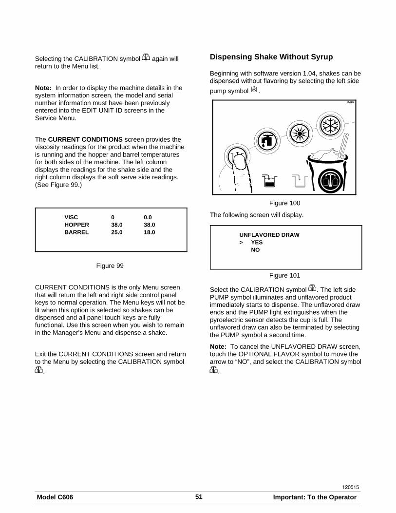
51Model C606 Important: To the Operator
120515
Selecting the CALIBRATION symbol again willreturn to the Menu list.
Note: In order to display the machine details in thesystem information screen, the model and serialnumber information must have been previouslyentered into the EDIT UNIT ID screens in theService Menu.
The CURRENT CONDITIONS screen provides theviscosity readings for the product when the machineis running and the hopper and barrel temperaturesfor both sides of the machine. The left columndisplays the readings for the shake side and theright column displays the soft serve side readings.(See Figure 99.)
VISC 0 0.0HOPPER 38.0 38.0BARREL 25.0 18.0
Figure 99
CURRENT CONDITIONS is the only Menu screenthat will return the left and right side control panelkeys to normal operation. The Menu keys will not belit when this option is selected so shakes can bedispensed and all panel touch keys are fullyfunctional. Use this screen when you wish to remainin the Manager's Menu and dispense a shake.
Exit the CURRENT CONDITIONS screen and returnto the Menu by selecting the CALIBRATION symbol
.
Dispensing Shake Without Syrup
Beginning with software version 1.04, shakes can bedispensed without flavoring by selecting the left side
pump symbol .
Figure 100
The following screen will display.
UNFLAVORED DRAW> YES
NO
Figure 101
Select the CALIBRATION symbol . The left sidePUMP symbol illuminates and unflavored productimmediately starts to dispense. The unflavored drawends and the PUMP light extinguishes when thepyroelectric sensor detects the cup is full. Theunflavored draw can also be terminated by selectingthe PUMP symbol a second time.
Note: To cancel the UNFLAVORED DRAW screen,touch the OPTIONAL FLAVOR symbol to move thearrow to “NO”, and select the CALIBRATION symbol
.
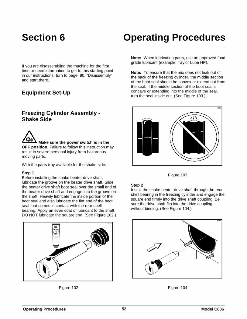
52 Model C606Operating Procedures
Section 6 Operating Procedures
If you are disassembling the machine for the firsttime or need information to get to this starting pointin our instructions, turn to page 90, “Disassembly”and start there.
Equipment Set-Up
Freezing Cylinder Assembly -Shake Side
Make sure the power switch is in theOFF position. Failure to follow this instruction mayresult in severe personal injury from hazardousmoving parts.
With the parts tray available for the shake side:
Step 1Before installing the shake beater drive shaft,lubricate the groove on the beater drive shaft. Slidethe beater drive shaft boot seal over the small end ofthe beater drive shaft and engage into the groove onthe shaft. Heavily lubricate the inside portion of theboot seal and also lubricate the flat end of the bootseal that comes in contact with the rear shellbearing. Apply an even coat of lubricant to the shaft.DO NOT lubricate the square end. (See Figure 102.)
Figure 102
Note: When lubricating parts, use an approved foodgrade lubricant (example: Taylor Lube HP).
Note: To ensure that the mix does not leak out ofthe back of the freezing cylinder, the middle sectionof the boot seal should be convex or extend out fromthe seal. If the middle section of the boot seal isconcave or extending into the middle of the seal,turn the seal inside out. (See Figure 103.)
Figure 103
Step 2Install the shake beater drive shaft through the rearshell bearing in the freezing cylinder and engage thesquare end firmly into the drive shaft coupling. Besure the drive shaft fits into the drive couplingwithout binding. (See Figure 104.)
Figure 104

53Model C606 Operating Procedures
Step 3Check scraper blades for any nicks or signs of wear.If any nicks are present, replace the blades.
Note: Shake side scraper blades should bereplaced every 6 months.
Step 4If the blades are in good condition, place eachscraper blade over the holding pins on the beaterassembly. (See Figure 105.)
Figure 105
Note: The holes in the scraper blade must fit overthe pins to prevent damage.
Step 5Holding the blades on the beater assembly, insertthe beater assembly in the freezing cylinder. Engagethe shaft end firmly into the drive shaft socket. (SeeFigure 106.)
Figure 106
Note: When properly seated, the beater will notprotrude beyond the front of the freezing cylinder.
Step 6Assemble the draw valve spinner assembly. Inspectdraw valve o-rings for cuts or nicks. (Replace if cutor nicked.) If draw valve o-rings are in goodcondition, slide the 2 o-rings into the grooves of thedraw valve and lubricate. (See Figure 107.)
Figure 107
Step 7Lubricate the outer diameter of the spinner shaftseal. Fill the cups on each end of the seal withlubricant.
Figure 108
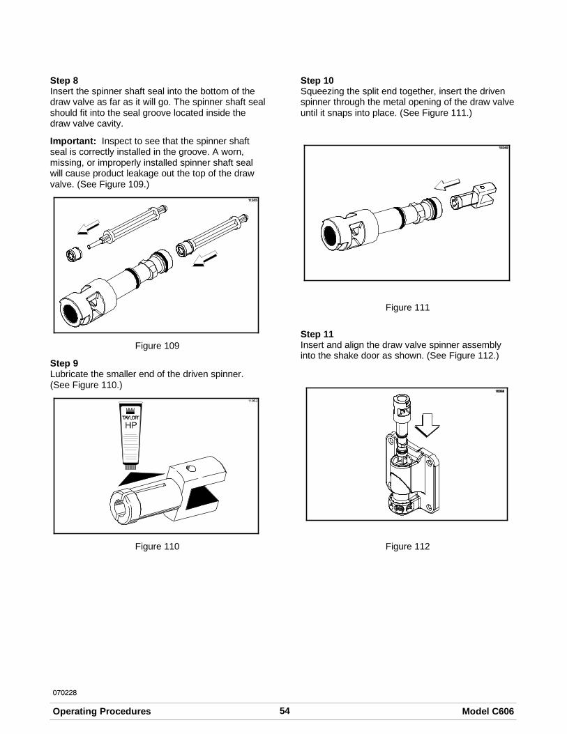
54 Model C606Operating Procedures
070228
Step 8Insert the spinner shaft seal into the bottom of thedraw valve as far as it will go. The spinner shaft sealshould fit into the seal groove located inside thedraw valve cavity.
Important: Inspect to see that the spinner shaftseal is correctly installed in the groove. A worn,missing, or improperly installed spinner shaft sealwill cause product leakage out the top of the drawvalve. (See Figure 109.)
Figure 109
Step 9Lubricate the smaller end of the driven spinner.(See Figure 110.)
Figure 110
Step 10Squeezing the split end together, insert the drivenspinner through the metal opening of the draw valveuntil it snaps into place. (See Figure 111.)
Figure 111
Step 11Insert and align the draw valve spinner assemblyinto the shake door as shown. (See Figure 112.)
Figure 112

55Model C606 Operating Procedures
Step 12Place the freezer door o-ring into the groove on theback of the freezer door. Lubricate the outsidediameter of the front bearing. Slide the front bearinginto the door hub.
Note: If necessary, put two small spots of lubricantat the 10 o'clock and 2 o'clock positions on theupper portion of the freezer door o-ring to keep it inplace.
Figure 113
Step 13Install the shake freezer door. Position the freezerdoor on the four studs on the front of the freezingcylinder. Align the top of the draw valve with theactuator bracket. Install the handscrews (shorthandscrews at the bottom of the door). Tightenequally in a criss-cross pattern to insure the door issnug. Do not over-tighten.
Figure 114
Step 14Lubricate the shaft of the spinner blade up to thegroove. (See Figure 115.)
Figure 115
Step 15Insert the spinner blade shaft into the center of thedriven spinner, and through the draw valve cavityuntil the shaft appears at the top of the draw valve.The spinner blade must be aligned and engaged tothe driven spinner at the bottom. This allows thespinner shaft to raise high enough to be engagedinto the spinner coupling at the top. (SeeFigure 116.)
Figure 116

56 Model C606Operating Procedures
040803
Step 16Raise the locking collar of the spinner coupling andinsert the spinner shaft into the cavity of the couplinguntil the locking collar can drop into the lockedposition. (See Figure 117.)
Figure 117
Step 17Snap the restrictor cap over the end of the doorspout and install the syrup valve retainer pins.(See Figure 118.)
Figure 118
Freezing Cylinder Assembly - SoftServe Side
Make sure the power switch is in the OFFposition. Failure to follow this instruction may resultin severe personal injury from hazardous movingparts.
With the parts tray available for the soft serve side:
Step 1Before installing the soft serve beater drive shaft,lubricate the groove on the beater drive shaft. Slidethe beater drive shaft boot seal over the small end ofthe beater drive shaft and engage into the groove onthe shaft. Heavily lubricate the inside portion of theboot seal and also lubricate the flat end of the bootseal that comes in contact with the rear shellbearing. Apply an even coat of lubricant to the shaft.DO NOT lubricate the hex end. (See Figure 119.)
Figure 119
Note: When lubricating parts, use an approved foodgrade lubricant (example: Taylor Lube HP).
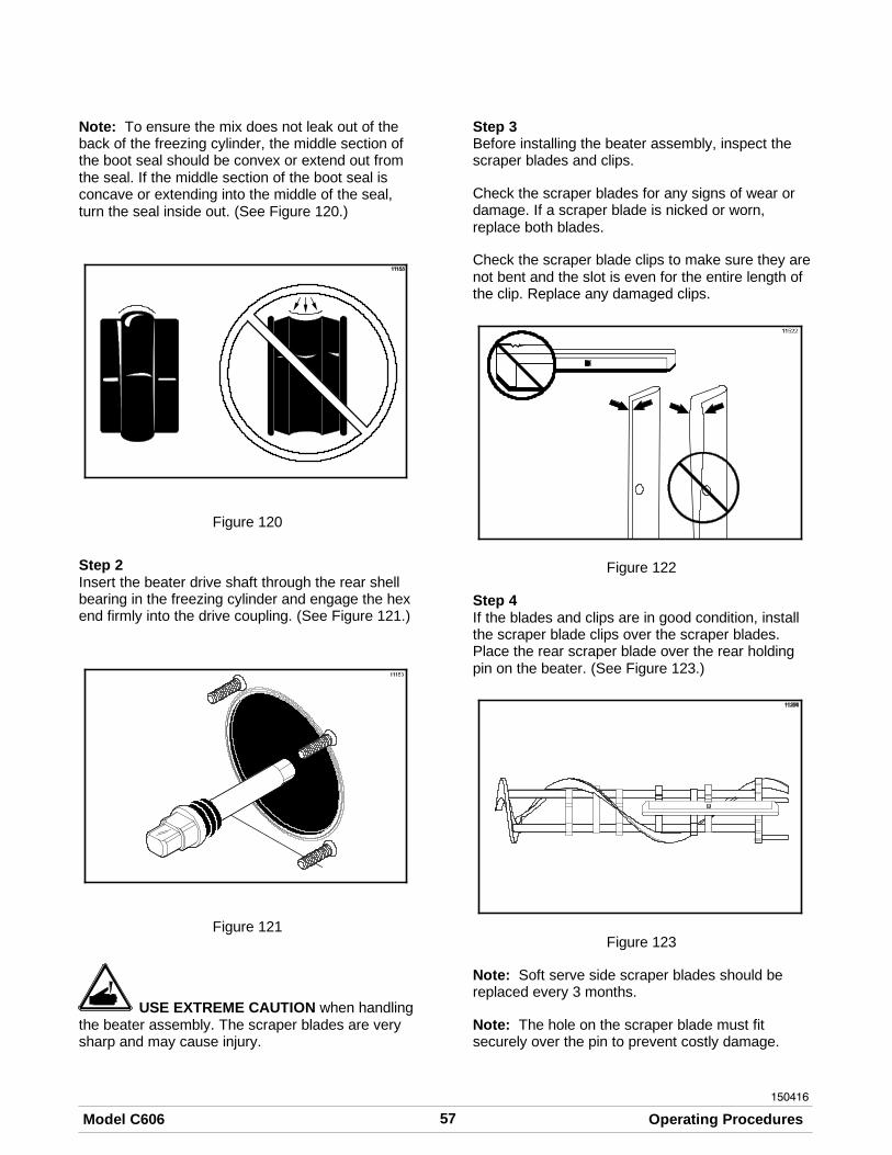
57Model C606 Operating Procedures
150416
Note: To ensure the mix does not leak out of theback of the freezing cylinder, the middle section ofthe boot seal should be convex or extend out fromthe seal. If the middle section of the boot seal isconcave or extending into the middle of the seal,turn the seal inside out. (See Figure 120.)
Figure 120
Step 2Insert the beater drive shaft through the rear shellbearing in the freezing cylinder and engage the hexend firmly into the drive coupling. (See Figure 121.)
Figure 121
USE EXTREME CAUTION when handlingthe beater assembly. The scraper blades are verysharp and may cause injury.
Step 3Before installing the beater assembly, inspect thescraper blades and clips.
Check the scraper blades for any signs of wear ordamage. If a scraper blade is nicked or worn,replace both blades.
Check the scraper blade clips to make sure they arenot bent and the slot is even for the entire length ofthe clip. Replace any damaged clips.
Figure 122
Step 4If the blades and clips are in good condition, installthe scraper blade clips over the scraper blades.Place the rear scraper blade over the rear holdingpin on the beater. (See Figure 123.)
Figure 123
Note: Soft serve side scraper blades should bereplaced every 3 months.
Note: The hole on the scraper blade must fitsecurely over the pin to prevent costly damage.

58 Model C606Operating Procedures
150415
Step 5Holding the rear blade on the beater, slide it into thefreezing cylinder halfway. Install the front scraperblade over the front holding pin. (See Figure 124.)
Figure 124
Step 6Before installing the beater shoes, check the shoesfor any nicks, cracks, or signs of wear. If any defectsare present, replace the beater shoes.
Step 7If the beater shoes are in good condition, install thebeater shoes. (See Figure 125.)
Figure 125
Step 8Slide the beater assembly the rest of the way intothe freezing cylinder. Make sure the beaterassembly is in position over the drive shaft byturning the beater slightly until the beater is properly
seated. When in position, the beater will not protrudebeyond the front of the freezing cylinder.(See Figure 126.)
Figure 126
Step 9Before assembling the freezer door, check thefollowing for any nicks, cracks, or signs of wear:door bearing, door gasket, draw valve, o-rings, andall sides of the door assembly, including the inside ofthe draw valve bore. Replace any damaged parts.
Step 10If the parts are in good condition, slide the 3 o-ringsinto the grooves on the draw valve and lubricate.(See Figure 127.)
Figure 127
Step 11Lightly lubricate inside of the top of the freezer doorvalve cavity. (See Figure 128.)
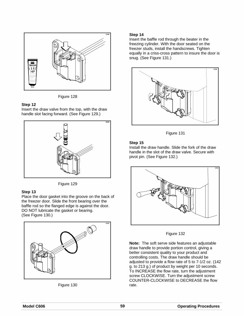
59Model C606 Operating Procedures
Figure 128
Step 12Insert the draw valve from the top, with the drawhandle slot facing forward. (See Figure 129.)
Figure 129
Step 13Place the door gasket into the groove on the back ofthe freezer door. Slide the front bearing over thebaffle rod so the flanged edge is against the door.DO NOT lubricate the gasket or bearing.(See Figure 130.)
Figure 130
Step 14Insert the baffle rod through the beater in thefreezing cylinder. With the door seated on thefreezer studs, install the handscrews. Tightenequally in a criss-cross pattern to insure the door issnug. (See Figure 131.)
Figure 131
Step 15Install the draw handle. Slide the fork of the drawhandle in the slot of the draw valve. Secure withpivot pin. (See Figure 132.)
Figure 132
Note: The soft serve side features an adjustabledraw handle to provide portion control, giving abetter consistent quality to your product andcontrolling costs. The draw handle should beadjusted to provide a flow rate of 5 to 7-1/2 oz. (142g. to 213 g.) of product by weight per 10 seconds.To INCREASE the flow rate, turn the adjustmentscrew CLOCKWISE. Turn the adjustment screwCOUNTER-CLOCKWISE to DECREASE the flowrate.

60 Model C606Operating Procedures
150415
Step 16Slide the long drip pan into the hole in the frontpanel above the syrup topping dispensers.(See Figure 133.)
Figure 133
Step 17Slide the two shorter drip pans into the holes in therear panel. Slide the two notched drip pans into theleft and right side panels. (See Figure 134.)
Figure 134
Step 18Install the front drip tray and splash shield under thedoor spouts. (See Figure 135.)
Figure 135
Mix Pump Assembly
Step 1Inspect the rubber and plastic pump parts. Theo-rings, check rings, and gaskets must be in 100%good condition for the pump and entire machine tooperate properly. They cannot properly serve theirintended function if nicks, cuts, or holes in thematerial are present.
Inspect the plastic pump parts for cracks, wear, andde-lamination of plastic.
Replace any defective parts immediately anddiscard the old.
Step 2Assemble the piston. Slide the red o-ring into thegroove of the piston. DO NOT lubricate the o-ring.(See Figure 136.)
Figure 136
Step 3Apply a thin layer of lubricant to the inside of thepump cylinder at the retaining pin hole end. (SeeFigure 137.)
Figure 137

61Model C606 Operating Procedures
Step 4Insert the piston into the retaining pin hole end of thepump cylinder. (See Figure 138.)
Figure 138
Step 5Assemble the valve cap. Slide the red o-ring into thegroove of the valve cap. DO NOT lubricate theo-ring. (See Figure 139.)
Figure 139
Step 6Slide the pump valve gasket into the holes on thecap. DO NOT lubricate the gasket.(See Figure 140.)
Figure 140
Step 7Insert the valve cap into the hole in the mix inletadapter. (See Figure 141.)
Figure 141

62 Model C606Operating Procedures
Step 8Insert the mix inlet assembly into the pump cylinder.(See Figure 142.)
Figure 142
Note: The adapter must be positioned into thenotch located at the end of the pump cylinder.
Step 9Secure the pump parts in position by sliding theretaining pin through the cross holes located at oneend of the pump cylinder. (See Figure 143.)
Figure 143
Note: The head of the retaining pin should belocated at the top of the pump when installed.
Step 10Assemble the feed tube assembly. Slide the checkring into the groove of the feed tube. (SeeFigure 144.)
Figure 144
Step 11Install one red o-ring on each end of the mix feedtube, and thoroughly lubricate. (See Figure 145.)
Figure 145

63Model C606 Operating Procedures
080716
Step 12Lay the pump assembly, pump clip, cotter pin andagitator in the bottom of the mix hopper forsanitizing. (See Figure 146.)
Figure 146
Step 13Slide the large black o-ring and the two smallerblack o-rings into the grooves on the drive shaft.Thoroughly lubricate the o-rings and shaft. DO NOTlubricate the hex end of the shaft. (See Figure 147.)
Figure 147
Step 14Install the hex end of the drive shaft into the drivehub at the rear wall of the mix hopper.(See Figure 148.)
Figure 148
Note: For ease in installing the pump, position theball crank of the drive shaft in the 3 o'clock position.
Sanitizing - Shake Side
Step 1Prepare a pail of an approved 100 PPM sanitizingsolution (examples: 2-1/2 gal. [9.5 liters] of Kay-5Ror 2 gal. [7.6 liters] of Stera-SheenR). USE WARMWATER AND FOLLOW THE MANUFACTURER'SSPECIFICATIONS.
Step 2Install syrup hole plugs in the syrup ports in thefreezer door. (See Figure 149.)
Figure 149

64 Model C606Operating Procedures
150619
Step 3Pour the sanitizing solution over all parts in thebottom of the mix hopper and allow it to flow into thefreezing cylinder.
Note: You have just sanitized the mix hopperand parts; therefore, be sure your hands areclean and sanitized before going on in theseinstructions.
Step 4Prepare two more pails of an approved 100 PPMsanitizing solution (examples: Kay-5® orStera-Sheen®). USE WARM WATER ANDFOLLOW THE MANUFACTURER'SSPECIFICATIONS.
Step 5Install the air/mix pump assembly at the rear of themix hopper. To position the pump on the drive hub,align the drive slot in the piston with the drive crankof the drive shaft. Secure the pump in place byslipping the pump clip over the collar of the pump,making sure the clip fits into the grooves in thecollar. (See Figure 150.)
Figure 150
Step 6
CAUTION!Install the pump end of the mix feed tube andsecure with the cotter pin. Failure to follow thisinstruction could result in sanitizer spraying on theoperator.
Step 7Using the white hopper brush, clean the mix levelsensing probes, the mix hopper, mix inlet hole, theoutside of the agitator drive shaft housing, theagitator, the air/mix pump, pump clip, mix feed tubeand cotter pin.
Step 8Pour the two pails of sanitizing solution into the mixhopper. The sanitizing solution should be within 1”(25 mm) of the top of the hopper.
Step 9Using the white hopper brush, scrub the exposedsides of the hopper. Wait at least five minutes beforeproceeding with these instructions.
Step 10Place the power switch in the ON position.
Step 11
Touch the WASH symbol . This will cause thesanitizing solution in the freezing cylinder to come incontact with all areas of the freezing cylinder.(See Figure 151.)
Figure 151
Step 12With a pail beneath the door spout, open and closethe draw valve six times.
Step 13
Touch the PUMP symbol to sanitize the inside ofthe air/mix pump and the mix feed tube.
Step 14Open the draw valve and draw off all the remainingsanitizing solution.
IMPORTANT! The unit must NOT be placed inAUTO until all sanitizing solution has beenremoved from the freezing cylinder and properpriming procedures have been completed.

65Model C606 Operating Procedures
150619
Failure to follow this instruction may result indamage to the freezing cylinder.
Step 15
Touch the WASH and PUMP symbols to stopthe WASH and PUMP modes and to close the drawvalve. (See Figure 152.)
Figure 152
Note: Be sure your hands are clean andsanitized before going on in these instructions.
Step 16Place the agitator on the agitator drive shafthousing. (See Figure 153.)
Figure 153
Note: If the agitator paddle should stop turningduring normal operation, with sanitized hands,remove the agitator from the agitator drive shafthousing and brush clean with sanitizing solution.Install the agitator back onto the agitator drive shafthousing.
Step 17Remove the cotter pin from the pump. Stand the mixfeed tube in the corner of the mix hopper. Place thecotter pin in position in the outlet fitting of the pump.
Figure 154
Step 18Remove the restrictor cap and the syrup hole plugs.
Step 19Return to the freezer with a small amount ofsanitizing solution. With a pail below the door spout,dip the door spout brush into the sanitizing solutionand brush clean the syrup ports in the freezer door,door spout, bottom of the driven spinner and spinnerblade, and syrup line fittings.
Note: To assure sanitary conditions are maintained,brush clean each item for a total of 60 seconds,repeatedly dipping the brush in sanitizing solution.
Step 20With the syrup port brush, brush each syrup porthole 10 to 15 times. Dip the brush in sanitizingsolution before brushing each port.
Step 21Fill the squeeze bottle with sanitizing solution. With apail beneath the door, insert the tube end of thesqueeze bottle into the syrup port, and squeeze thebottle firmly. This action will force solution out of theadjacent port and down around the spinner. Thisprocedure should be performed for at least 10seconds per port.
Step 22Install the syrup valves and the restrictor cap.

66 Model C606Operating Procedures
150619
Sanitizing - Soft Serve Side
Step 1Prepare a pail of an approved 100 PPM sanitizingsolution (examples: 2-1/2 gal. [9.5 liters] of Kay-5Ror 2 gal. [7.6 liters] of Stera-SheenR). USE WARMWATER AND FOLLOW THE MANUFACTURER'SSPECIFICATIONS.
Step 2Pour the sanitizing solution over all parts in thebottom of the mix hopper and allow it to flow into thefreezing cylinder.
Note: You have just sanitized the mix hopperand parts; therefore, be sure your hands areclean and sanitized before going on in theseinstructions.
While the solution is flowing into the freezingcylinder, take particular care to brush clean the mixlevel sensing probes, the mix hopper, mix inlet hole,the outside of the agitator housing, the agitator, theair/mix pump, pump clip, mix feed tube and cotterpin.
Step 3Install the pump assembly at the rear of the mixhopper. To position the pump on the drive hub, alignthe drive hole in the piston with the drive crank ofthe drive shaft. Secure the pump in place by slippingthe pump clip over the collar of the pump, makingsure the clip fits into the grooves in the collar.(See Figure 155.)
Figure 155
Step 4
CAUTION!Install the pump end of the mix feed tube andsecure with the cotter pin. Failure to follow this
instruction could result in sanitizer spraying on theoperator.
Step 5Prepare another pail of an approved 100 PPMsanitizing solution (examples: Kay-5® orStera-Sheen®). USE WARM WATER ANDFOLLOW THE MANUFACTURER'SSPECIFICATIONS.
Step 6Pour the sanitizing solution into the mix hopper.
Step 7Brush the exposed sides of the hopper. Wait at least5 minutes before proceeding with these instructions.
Step 8
Touch the WASH symbol . This will cause thesanitizing solution in the freezing cylinder to beagitated.
Step 9With a pail beneath the door spout, open the draw
valve and touch the PUMP symbol . Open andclose the draw valve 6 times. Open the draw valveand draw off the sanitizing solution.
Step 10
Touch the WASH and PUMP symbols andclose the draw valve. (See Figure 156.)
Figure 156
IMPORTANT! The unit must NOT be placed inAUTO until all sanitizing solution has beenremoved from the freezing cylinder and properpriming procedures have been completed.Failure to follow this instruction may result indamage to the freezing cylinder.
Note: Be sure your hands are clean andsanitized before going on in these instructions.

67Model C606 Operating Procedures
150619
Step 11Place the agitator on the agitator drive shafthousing. (See Figure 157.)
Figure 157
Note: If agitator should stop turning during normaloperation, with sanitized hands, remove agitatorfrom agitator drive shaft housing and brush cleanwith sanitizing solution. Install the agitator back ontothe agitator drive shaft housing.
Step 12Remove the cotter pin from the pump. Stand the mixfeed tube in the corner of the mix hopper. Place thecotter pin in position in the outlet fitting of the pump.(See Figure 158.)
Figure 158
Note: You have just sanitized all food contactsurfaces of the freezer.
Priming - Shake Side
Note: Use only FRESH MIX when priming thefreezer.
Step 1With a pail beneath the door spout, touch any
FLAVOR SELECT symbol to open the drawvalve. Pour 2-1/2 gallons (9.5 liters) of FRESH mixinto the mix hopper and allow it to flow into thefreezing cylinder. This will force out any remainingsanitizing solution. When full strength mix is flowingfrom the door spout, touch any FLAVOR SELECT
symbol to close the draw valve.
IMPORTANT! Failure to remove all sanitizingsolution may result in damage to the freezingcylinder.
Step 2When mix stops bubbling down into the freezingcylinder, remove the cotter pin from the outlet fittingof the mix pump. Insert the outlet end of the mixfeed tube into the mix inlet hole in the mix hopper.Place the inlet end of the mix feed tube into theoutlet fitting of the mix pump. Secure with cotter pin.(See Figure 159.)
Figure 159

68 Model C606Operating Procedures
150619
Step 3Install the shake cup holder. (See Figure 160.)
Figure 160
Step 4
Select the AUTO symbol .
Step 5Fill the hopper with fresh mix and place the mixhopper cover in position.
Priming - Soft Serve Side
Note: Use only FRESH MIX when priming thefreezer.
Step 1With a pail beneath the door spout, open the drawvalve. Pour 2-1/2 gallons (9.5 liters) of FRESH mixinto the mix hopper and allow it to flow into thefreezing cylinder. This will force out any remainingsanitizing solution. When full strength mix is flowingfrom the door spout, close the draw valve.
IMPORTANT! Failure to remove all sanitizingsolution may result in damage to the freezingcylinder.
Step 2When mix stops bubbling down into the freezingcylinder, remove the cotter pin from the outlet fittingof the mix pump. Insert the outlet end of the mixfeed tube into the mix inlet hole in the mix hopper.Place the inlet end of the mix feed tube into theoutlet fitting of the mix pump. Secure with cotter pin.
Step 3
Select the AUTO symbol .
Note: This procedure should be done 15 minutesbefore product is expected to be served.
Step 4Fill the hopper with fresh mix and place the mixhopper cover in position.
Daily Closing Procedures
This procedure must be done at the close ofbusiness.
Shake Side
Important: Fill the mix hopper with mix up to the filllevel indicator on the agitator paddle.(See Figure 161.)
Figure 161
Both sides of the freezer must be in the AUTO mode
(AUTO symbol is illuminated) or in the STANDBY
mode (STANDBY symbols and areilluminated) before the HEAT cycle may be started.
Note: If the BRUSH CLEAN COUNTER display hascounted down to 1 day, do not add mix. Themachine must be disassembled and brush cleanedwithin 24 hours.
Step 1Remove the hopper cover, shake cup holder, splashshield and drip pans.
Make sure your hands are clean and sanitizedbefore performing these next steps.
Note: Select the CALIBRATION symbol to stopagitator movement for 10 seconds. Select the
CALIBRATION symbol again to exit thecalibration mode. The agitator will automaticallyrestart after 10 seconds.
Step 2Remove the agitator from the mix hopper and therestrictor cap from the shake freezer door spout.

69Model C606 Operating Procedures
041008
Step 3Take the agitator, hopper cover, shake cup holder,drip pans, front drip tray, splash shield and restrictorcap to the sink for further cleaning and sanitizing.
Take the syrup hole plugs, spout cap, and spout capo-ring to the sink for further cleaning and sanitizing.
Step 4Rinse these parts in cool, clean water.
Step 5Prepare a small amount of an approved 100 PPMcleaning solution (examples: Kay-5® orStera-Sheen®). USE WARM WATER ANDFOLLOW THE MANUFACTURER'SSPECIFICATIONS.
Step 6Brush clean these parts.
Step 7Place the restrictor cap, front drip tray, shake cupholder and splash shield on a clean, dry surface toair-dry overnight or until the heating cycle iscomplete.
Step 8Prepare a small amount of an approved 100 PPMsanitizing solution (examples: Kay-5® orStera-Sheen®). USE WARM WATER ANDFOLLOW THE MANUFACTURER'SSPECIFICATIONS.
Step 9Sanitize the syrup hole plugs, spout cap, spout capo-ring, drip pans, agitator, and hopper cover.
Step 10Install the agitator back onto the agitator drive shafthousing. Replace the hopper cover.(See Figure 162.)
Figure 162
Important: If you do not install the agitator correctly,the machine will fail the heat cycle and will lock outin the morning.
Step 11Remove the syrup lines from the freezer door.(See Figure 163.)
Figure 163
Step 12Return to the freezer with a small amount ofcleaning solution. With a pail below the door spout,dip the door spout brush into the cleaning solutionand brush clean the syrup ports in the freezer door,door spout and bottom of the driven spinner, spinnerblade, and syrup line fittings. (See Figure 164.)
Figure 164
Note: To assure sanitary conditions are maintained,brush each item for a total of 60 seconds, repeatedlydipping the brush in the cleaning solution.
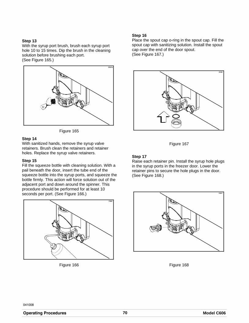
70 Model C606Operating Procedures
041008
Step 13With the syrup port brush, brush each syrup porthole 10 to 15 times. Dip the brush in the cleaningsolution before brushing each port.(See Figure 165.)
Figure 165
Step 14With sanitized hands, remove the syrup valveretainers. Brush clean the retainers and retainerholes. Replace the syrup valve retainers.
Step 15Fill the squeeze bottle with cleaning solution. With apail beneath the door, insert the tube end of thesqueeze bottle into the syrup ports, and squeeze thebottle firmly. This action will force solution out of theadjacent port and down around the spinner. Thisprocedure should be performed for at least 10seconds per port. (See Figure 166.)
Figure 166
Step 16Place the spout cap o-ring in the spout cap. Fill thespout cap with sanitizing solution. Install the spoutcap over the end of the door spout.(See Figure 167.)
Figure 167
Step 17Raise each retainer pin. Install the syrup hole plugsin the syrup ports in the freezer door. Lower theretainer pins to secure the hole plugs in the door.(See Figure 168.)
Figure 168

71Model C606 Operating Procedures
080723
Step 18Fill the squeeze bottle with sanitizing solution. Holdthe bottle over a pail. Squeeze the bottle andthoroughly rinse the slot of each syrup nose fitting.
Figure 169
Step 19Wipe the outside of each syrup nose fitting with asanitized towel.
Step 20Using a clean, sanitized towel, wipe down thefreezer door, front panel, the area around the bottomof the freezer door, and any other areas thatdemonstrate a build-up of either moisture or foodsubstance.
Soft Serve Side
This procedure must be done at the close ofbusiness.
Important: Fill the mix hopper with mix up to the filllevel indicator on the agitator paddle. (See Figure170.)
Figure 170
Note: If the BRUSH CLEAN COUNTER display hascounted down to one day, do not add mix. Themachine must be disassembled and brush cleanedwithin 24 hours.
Both sides of the freezer must be in the AUTO
(AUTO symbol is illuminated) or in the STANDBY
mode (STANDBY symbols and areilluminated) before the HEAT cycle may be started.
Step 1Place the heater topping switches in the OFF
position by touching the heater symbols . Thesymbols will not be illuminated when the heaters areoff. (See Figure 171.)
Figure 171
Step 2Remove the hopper cover.
MAKE SURE YOUR HANDS ARE CLEAN ANDSANITIZED BEFORE PERFORMING THESENEXT STEPS.
Note: Select the CALIBRATION symbol to stopagitator movement for 10 seconds. Select the
CALIBRATION symbol again to exit thecalibration mode. The agitator will automaticallyrestart after 10 seconds.
Step 3Remove the agitator from the mix hopper.
Step 4Take the agitator and hopper cover to the sink forfurther cleaning and sanitizing.
Step 5Rinse these parts in cool, clean water.

72 Model C606Operating Procedures
Step 6Prepare a small amount of an approved 100 PPMsanitizing solution (examples: Kay-5® orStera-Sheen®). USE WARM WATER ANDFOLLOW THE MANUFACTURER'SSPECIFICATIONS. Brush clean the parts.
Step 7Prepare a small amount of an approved 100 PPMsanitizing solution (examples: Kay-5® or Stera-Sheen®). USE WARM WATER AND FOLLOW THEMANUFACTURER'S SPECIFICATIONS. Sanitizethe agitator and hopper cover.
Step 8Install the agitator back onto the agitator drive shafthousing. Replace the hopper cover.
Important: If you do not install the agitator correctly,the machine will fail the heat cycle and will lock outin the morning.
Step 9Return to the freezer with a small amount ofcleaning solution. Dip the door spout brush into thecleaning solution and brush clean the door spoutand bottom of the draw valve.
Note: To assure sanitary conditions are maintained,brush each item for a total of 60 seconds, repeatedlydipping the brush in cleaning solution.(See Figure 172.)
Figure 172
Step 10Remove, clean and reinstall the long drip panthrough the front panel. (See Figure 173.)
Figure 173
Step 11Remove, clean and reinstall the two short drip pansin the rear panel.
Step 12Remove, clean and reinstall the two notched drippans in the left and right side panels.(See Figure 174.)
Figure 174
Step 13Using a clean, sanitized towel, wipe down thefreezer door, front panel, the area around the bottomof the freezer door, and any other areas thatdemonstrate a build-up of either moisture or foodsubstance.
The heat cycle will start at the AUTO HEAT TIMEsetting in the Manager's Menu (see page 42).
There are three phases of the heat cycle: Heating,Holding and Cooling. Each phase has a time limit. Ifany one of the three phases fail to reach the propertemperatures within the time limit, the cycle will

73Model C606 Operating Procedures
automatically abort and return to the STANDBYmode.
A failure message will appear on the vacuumfluorescent display (VFD) to inform the operator thatthe machine did not successfully complete the heattreatment cycle. The product may not be safe toserve. The freezer will be locked out (softlock) of theAUTO mode. The operator will be given the option
of selecting the HEAT symbol which will begin a
new heat cycle, or touching the WASH symbolwhich will place the side(s) into the OFF mode toallow a brush clean of the machine.
Note: Once the heating cycle has started, it cannotbe interrupted. The heating cycle will take amaximum of 4 hours to complete with full hoppers.
DO NOT attempt to draw product ordisassemble the unit during the HEAT cycle. Theproduct is hot and under extreme pressure.
When the heating cycle is complete, the control willreturn to the STANDBY mode. The STANDBY
symbols and will be illuminated.
Daily Opening Procedures
Before performing the opening procedures, checkthe display panel for any error messages. Normallythe display is blank unless an operational fault hasoccurred. If a fault has been detected, investigatethe cause and follow the instructions on the displaybefore proceeding with the opening procedures.(See Failure Messages, pages 35 and 45.)
Set-Up - Complete The Following
Make sure your hands are clean and sanitizedbefore performing these next steps.
Step 1With the drain plugs closed, check the water level inthe two heated topping wells. Fill the wells withwater to the indicating mark on the bottom of thewell.
Step 2Place the topping heaters in the ON position by
touching the topping heater symbols .
CAUTION: As soon as the heaters are turned on,the topping wells will begin heating. Thisheating process will take approximately 2-1/2hours to reach temperature. The water level inthe wells should be checked daily.
Step 3Prepare a pail of an approved 100 PPM sanitizingsolution (examples: Kay-5® or Stera-Sheen®).USE WARM WATER AND FOLLOW THEMANUFACTURER'S SPECIFICATIONS. Sanitizethe topping pumps by placing the entire pumpassembly in the pail of sanitizing solution. Pump thesolution through to thoroughly sanitize the pump.
Step 4Fill the topping containers with topping. Place thecaramel and fudge topping containers in the heatedwells. Place the remaining two topping containers inthe unheated wells. Cover the containers.
Step 5Sanitize the two topping ladles and place in the coldtopping containers.
Step 6Fill the cup dispensers, cup lid holder, and conedispenser.
Step 7To fill the cone dispenser, slide the drawer up andpull out. Push the spring guide all the way back to itslocking position. Place the cones in the drawer andrelease the spring guide.
Shake Side
Step 1When the heating cycle is complete, the heat cycle
symbols will no longer be illuminated and themachine will automatically enter the STANDBYmode. Prepare a small amount of an approved 100PPM sanitizing solution (examples: Kay-5® orStera-Sheen®). USE WARM WATER ANDFOLLOW THE MANUFACTURER'SSPECIFICATIONS.
Step 2Remove the syrup hole plugs, the syrup valveretainers, and the valve cap from the freezer door.Sanitize the restrictor cap, syrup hole plugs, syrupvalve retainers, spout cap and o-ring, shake cupholder, front drip tray and splash shield, in thissolution.

74 Model C606Operating Procedures
040803
Step 3Return to the freezer with a small amount ofsanitizing solution. With a pail below the door spout,dip the door spout brush into the sanitizing solution.Brush clean the door spout, the bottom of the drivenspinner and spinner blade, and the syrup linefittings. (See Figure 175.)
Figure 175
Note: To assure sanitary conditions are maintained,brush clean each item for a total of 60 seconds,repeatedly dipping the brush in sanitizing solution.
Step 4With the syrup port brush, brush each syrup porthole 10 to 15 times. Dip the brush in sanitizingsolution before brushing each port.(See Figure 176.)
Figure 176
Step 5Fill the squeeze bottle with sanitizing solution. With apail beneath the door, insert the tube end of thesqueeze bottle into the syrup port, and squeeze thebottle firmly. This action will force solution out of theadjacent port and down around the spinner. Thisprocedure should be performed for at least 10seconds per port. (See Figure 177.)
Figure 177
Step 6Reinstall the syrup valve retainers.
Step 7Install the restrictor cap on the freezer door spout.(See Figure 178.)
Figure 178

75Model C606 Operating Procedures
050112
Step 8With the pail still beneath the door, remove thesyrup nose fitting from the syrup line fitting byturning it counter-clockwise. Hold the syrup fittings inan “up“ position to minimize syrup loss.(See Figure 179.)
Figure 179
Step 9Remove the duckbill valve and o-ring from the syrupnose fitting.
Figure 180
Step 10Using the white end of the double-ended brush,scrub the inside of the syrup nose fitting to removeany residual particles.
Step 11Using a shake cup filled with an approved 100 PPMsanitizing solution, rinse the syrup nose fittingthoroughly.
Step 12Using a clean, sanitized towel, gently wipe any syrupfrom the duckbill valve.
Step 13Using a shake cup filled with sanitizing solution,thoroughly rinse the duckbill valve.
Step 14Install the duckbill valve into the syrup nose fittingwith the flat end aligned with the open slot in thesyrup nose fitting.
Note: Replace the duckbill valve if it is damaged orextends past the syrup nose fitting slot.(See Figure 181.)
Figure 181
Step 15Install the syrup nose fitting onto the syrup linefitting. Tighten by hand until snug.
Note: The duckbill valve must be wet when thesyrup nose fitting is assembled on the syrup linefitting. The sanitized water will lubricate the bottomflat surface and prevent the duckbill from twistingwhen the the syrup nose fitting is tightened.
Step 16Inspect the duckbill valve for proper installationinside the syrup nose fitting. The tip of the duckbillvalve must be flat to seal the syrup line.(See Figure 182.)
Figure 182
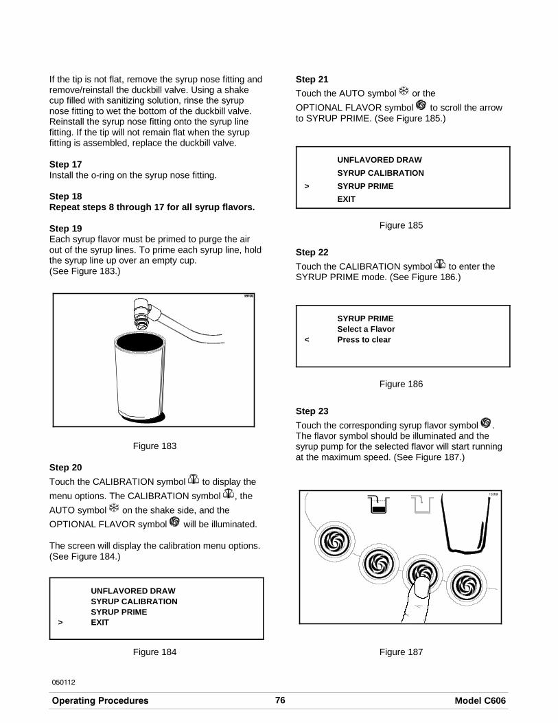
76 Model C606Operating Procedures
050112
If the tip is not flat, remove the syrup nose fitting andremove/reinstall the duckbill valve. Using a shakecup filled with sanitizing solution, rinse the syrupnose fitting to wet the bottom of the duckbill valve.Reinstall the syrup nose fitting onto the syrup linefitting. If the tip will not remain flat when the syrupfitting is assembled, replace the duckbill valve.
Step 17Install the o-ring on the syrup nose fitting.
Step 18Repeat steps 8 through 17 for all syrup flavors.
Step 19Each syrup flavor must be primed to purge the airout of the syrup lines. To prime each syrup line, holdthe syrup line up over an empty cup.(See Figure 183.)
Figure 183
Step 20
Touch the CALIBRATION symbol to display the
menu options. The CALIBRATION symbol , the
AUTO symbol on the shake side, and the
OPTIONAL FLAVOR symbol will be illuminated.
The screen will display the calibration menu options.(See Figure 184.)
UNFLAVORED DRAWSYRUP CALIBRATIONSYRUP PRIME
> EXIT
Figure 184
Step 21
Touch the AUTO symbol or the
OPTIONAL FLAVOR symbol to scroll the arrowto SYRUP PRIME. (See Figure 185.)
UNFLAVORED DRAW
SYRUP CALIBRATION
> SYRUP PRIME
EXIT
Figure 185
Step 22
Touch the CALIBRATION symbol to enter theSYRUP PRIME mode. (See Figure 186.)
SYRUP PRIMESelect a Flavor
< Press to clear
Figure 186
Step 23
Touch the corresponding syrup flavor symbol .The flavor symbol should be illuminated and thesyrup pump for the selected flavor will start runningat the maximum speed. (See Figure 187.)
Figure 187

77Model C606 Operating Procedures
041008
Step 24When a steady stream of syrup is flowing from thesyrup valve and all air has been purged from the
syrup line, touch any syrup flavor symbol to stopthe pump.
Step 25Repeat steps 23 - 24 to prime the rest of the syruplines. After priming is complete, exit the SYRUPPRIME mode by touching the CALIBRATION
symbol .
Step 26Using the squeeze bottle filled with sanitizingsolution, sanitize the syrup valve nose fittings.
Step 27Lubricate the o-ring. Raise the syrup valve retainer.Install the syrup valve. Push the syrup valve retainerdown to hold the valve in place. Repeat thisprocedure for each syrup valve. (See Figure 188.)
Figure 188
Note: Do not install an empty syrup line in thefreezer door. Insert a syrup port plug in the doorwhenever a syrup line is not in use. This will preventan accumulation of mix inside the valve fitting andthe syrup line.
Step 28Using a clean, sanitized towel, wipe down thefreezer door, front panel, the area around the bottomof the freezer door, and any other areas thatdemonstrate a build-up of either moisture or foodsubstance.
Step 29Install the shake cup holder, the front drip tray andthe splash shield.
Step 30When ready to resume normal operation, touch the
AUTO symbol . (See Figure 189.) The control hasa feature in the Manager's Menu to enable or disablethe AUTO START feature. When AUTO START inenabled, the machine will automatically exit theSTANDBY mode and start both sides in the AUTOmode at a designated time each day.
Figure 189
Note: Placing the machine in AUTO should beperformed approximately 15 minutes prior to servingproduct.
Soft Serve Side
Step 1Prepare a small amount of an approved 100 PPMsanitizing solution. USE WARM WATER ANDFOLLOW THE MANUFACTURER'SSPECIFICATIONS.
Step 2Return to the freezer with a small amount ofsanitizing solution. Dip the door spout brush into thesanitizing solution and brush clean the door spout,and bottom of the draw valve. (See Figure 190.)
Figure 190

78 Model C606Operating Procedures
041013
Note: To assure sanitary conditions are maintained,brush clean each item for a total of 60 seconds,repeatedly dipping the brush in sanitizing solution.
Step 3Using a clean, sanitized towel, wipe down thefreezer door, front panel, the area around the bottomof the freezer door, and any other areas thatdemonstrate a build-up of either moisture or foodsubstance.
Step 4When ready to resume normal operation, touch the
AUTO symbol . (See Figure 191.) The control hasa feature in the Manager's Menu to enable or disablethe AUTO START feature. When AUTO START inenabled, the machine will automatically exit theSTANDBY mode and start both sides in the AUTOmode at a designated time each day. (See page 42.)
Figure 191
Note: This procedure should be performed 15minutes prior to serving product.
Syrup System
Syrup Calibration
Calibrating the syrup flow should be performedweekly when the syrup system is cleaned. It is vitalthat the correct amount of syrup be incorporated intothe frozen mix to obtain a quality shake.
To determine the rate of syrup flow, you will need acalibration cup indicating fluid ounces. The properrate of syrup flow is 1 fl. oz. (30 ml) of syrup in 5seconds. For thick viscosity shake syrups, theproper syrup flow rate is 1 fl. oz. +/- 1/8 fl. oz. (30 ml+/- 4 ml) in 7 seconds. Once this rate is set, thecorrect amount of syrup will be blended with theshake base regardless of the size of shake served.Please note that syrup calibration is critical whenchanging the promotional 4th flavor syrup.
Calibration Procedure
Syrup lines must be properly primed with syrup toeliminate air in the line before the calibrationprocedure is performed. (See the Syrup PrimingProcedures on page 80.)
Step 1
Touch the CALIBRATION symbol to display the
menu options. The CALIBRATION symbol , the
AUTO symbol on the Shake side, and the
OPTIONAL FLAVOR symbol will be illuminated.(See Figure 192.)
Figure 192

79Model C606 Operating Procedures
041008
The screen will display the calibration menu options.(See Figure 193.)
UNFLAVORED DRAWSYRUP CALIBRATIONSYRUP PRIME
> EXIT
Figure 193
Note: When the CALIBRATION screen is
displayed, the flavor selection symbols will notraise the draw valve to dispense shake product.
Step 2
Touch the AUTO symbol or the OPTIONAL
FLAVOR symbol to scroll the arrow to SYRUPCALIBRATION. (See Figure 194.)
UNFLAVORED DRAW> SYRUP CALIBRATION
SYRUP PRIMEEXIT
Figure 194
Step 3
Touch the CALIBRATION symbol to enter thesyrup calibration mode. (See Figure 195.)
SYRUP CALIBRATIONSelect a Flavor
< Press to clear
Figure 195
Step 4Disconnect the syrup valve from the freezer door.Raise the syrup valve retainer and pull the valvestraight out. (See Figure 196.)
Figure 196
Step 5To calibrate the syrup dispensing rate, hold thesmall portion of the calibration cup under the valvefor the flavor to be calibrated. Touch the
corresponding FLAVOR SELECT symbol toactivate the syrup pump and start the flow of syrup.When the syrup level measures one ounce, touch
the same FLAVOR SELECT symbol to stop thesyrup flow.
Verify the level of syrup in the cup. If themeasurement is not within the specification, repeatstep 4 for the same flavor until the correct syrupcalibration is achieved. (See Figure 197.)
Figure 197
Note: You can verify the syrup dispensing rate inthe Manager's Menu. (See “Verify Calibration” onpage 39.)
Step 6Repeat steps 4 and 5 for the remaining syrupflavors.

80 Model C606Operating Procedures
Step 7Exit the CALIBRATION mode by touching the
CALIBRATION symbol . A blank screen will
appear and the AUTO symbol and the
OPTIONAL FLAVOR symbol will return to theirnormal function.
Note: Whenever a particular syrup line is not used,the syrup hole plug found in the spare parts kit mustbe installed. Place the syrup hole plug o-ring into thegroove of the syrup hole plug, and lubricate. Installthe hole plug in the door. Lower the retaining pin tosecure the plug in place.
Syrup Priming Procedure
The purpose of priming the syrup line is to eliminateany air in the syrup delivery system. Air in the syrupline can cause irregular shake blending, flavorcarry-over, and syrup leaking from the door spoutafter the draw valve has closed. Each time a syrupcontainer is drained or replaced, prime the syrupsystem until all the air has been removed and thesyrup flow is uniform.
Step 1Retrieve a full syrup container from the dry storagearea.
Step 2Shake the syrup container prior to opening it. Openthe full syrup container.
Step 3Pull the feed tube from the empty syrup containerand clean the outside of the feed tube with a clean,sanitized towel.
For Syrup Bag System: Disconnect the empty bagand clean the hose connector fitting with a clean,sanitized towel. Attach the hose connector fitting toa full bag of syrup. Place the bag on the shelf in thesyrup compartment. Make sure the hose is notpinched and there are no kinks in the tubing.
Step 4Place the feed tube into the full syrup container andreplace the syrup container in the syrup cabinet.
Step 5Dispose of the empty syrup container.
Step 6Prime the syrup line by removing the syrup valvefrom the freezer and hold it over an empty cup.
Step 7
Touch the CALIBRATION symbol to display the
menu options. The CALIBRATION symbol , the
AUTO symbol on the shake side, and the
OPTIONAL FLAVOR symbol will be illuminated.
Note: The screen will display the calibration menuoptions. (See Figure 198.)
UNFLAVORED DRAWSYRUP CALIBRATIONSYRUP PRIME
> EXIT
Figure 198
Step 8
Touch the AUTO symbol or the
OPTIONAL FLAVOR symbol to scroll the arrowto SYRUP PRIME. (See Figure 199.)
UNFLAVORED DRAWSYRUP CALIBRATION
> SYRUP PRIMEEXIT
Figure 199
Step 9
Touch the CALIBRATION symbol to enter theSYRUP PRIME mode. (See Figure 200.)
SYRUP PRIMESelect a Flavor
< Press to clear
Figure 200

81Model C606 Operating Procedures
Step 10
Touch the corresponding syrup flavor symbol .The flavor symbol should be illuminated and thesyrup pump for the selected flavor will start runningat the maximum speed. (See Figure 201.)
Figure 201
Step 11When a steady stream of syrup is flowing from thesyrup valve and all air has been purged from the
syrup line, touch any syrup flavor symbol to stopthe pump.
Step 12Repeat steps 10 -11 for any other syrup lines to beprimed, or exit the SYRUP PRIME mode by
touching the CALIBRATION symbol .
Syrup Topping Pump
Syrup Topping Pump Disassembly
Before the first use, and after use weekly,disassemble and clean the pump.
Step 1Flush and rinse the pump in a container of warmwater. Place the lower end of the pump into thewater container. Operate the pump until only warmwater flows from the discharge tube.
Step 2Remove the pump from the container of water fordisassembly.
Step 3Remove the plunger assembly from the pump bodyby turning the plunger nut counterclockwise. (SeeFigure 202.)
Figure 202

82 Model C606Operating Procedures
Step 4To remove the knob, compress the spring towardthe knob, using the washer. Compress it enough tograb onto the plunger with your hand for support.Begin removing the knob with your other hand.Remove the knob o-ring. Remove the plunger nutfrom the plunger tube. (See Figure 203.)
Figure 203
Step 5Remove the plunger tube and the insert from theplunger assembly. (See Figure 204.)
Figure 204
Step 6Remove the spring and washer from the plungerassembly. (See Figure 205.)
Figure 205
Step 7Remove the seal assembly from the plungerassembly. (See Figure 206.)
Figure 206
Step 8Remove the seal o-ring from the seal. (SeeFigure 207.)
Figure 207

83Model C606 Operating Procedures
Step 9Remove the discharge tube lock nut by turning itcounterclockwise. Remove the discharge lock nutfrom the discharge tube. (See Figure 208.)
Figure 208
Step 10Remove the lid by sliding it off the discharge tube.
Step 11Remove the cylinder from the valve body. (SeeFigure 209.)
Figure 209
Step 12Remove the discharge tube from the valve body.(See Figure 210.)
Figure 210
Step 13Remove the 1-5/16” o-ring from the valve body, andremove the 1” o-ring from the discharge tube.
Cleaning the Syrup Pump
Step 1Wash and scrub all parts in an approved 100 PPMcleaning solution (examples: Kay-5® orStera-Sheen®).
Step 2Insert the black shielded brush through the tip of thedischarge tube. Move the brush back and forth toscrub the tip of the discharge tube. (SeeFigure 211.)
Figure 211
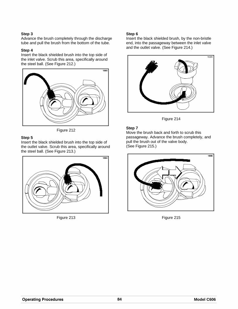
84 Model C606Operating Procedures
Step 3Advance the brush completely through the dischargetube and pull the brush from the bottom of the tube.
Step 4Insert the black shielded brush into the top side ofthe inlet valve. Scrub this area, specifically aroundthe steel ball. (See Figure 212.)
Figure 212
Step 5Insert the black shielded brush into the top side ofthe outlet valve. Scrub this area, specifically aroundthe steel ball. (See Figure 213.)
Figure 213
Step 6Insert the black shielded brush, by the non-bristleend, into the passageway between the inlet valveand the outlet valve. (See Figure 214.)
Figure 214
Step 7Move the brush back and forth to scrub thispassageway. Advance the brush completely, andpull the brush out of the valve body.(See Figure 215.)
Figure 215

85Model C606 Operating Procedures
Step 8Insert the black shielded brush into the bottom sideof the inlet valve. Move the brush back and forth toscrub this area, specifically around the steel ball.(See Figure 216.)
Figure 216
Step 9Advance the brush completely through the inletvalve, and pull the brush out of the valve body.
Step 10Rinse all parts with clear water.
Step 11Sanitize the parts in an approved 100 PPMsanitizing solution (examples: Kay-5® orStera-Sheen®). Allow the parts to air dry aftersanitizing.
Syrup Topping Pump Assembly
After pump disassembly and cleaning is complete,assemble the pump.
Step 1Lubricate and install the seal o-ring into the seal.(See Figure 217.)
Figure 217
Step 2Install the seal assembly onto the piston end of theplunger assembly.
Step 3Install the washer and spring onto the plungerassembly. (See Figure 218.)
Figure 218
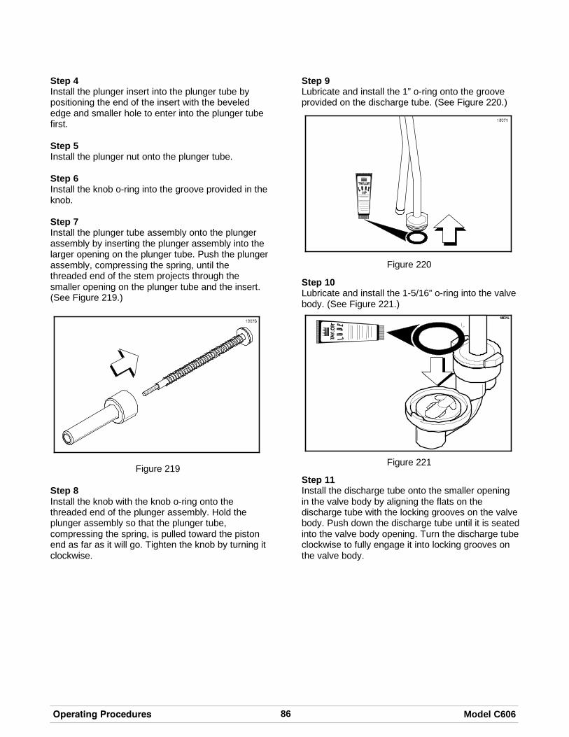
86 Model C606Operating Procedures
Step 4Install the plunger insert into the plunger tube bypositioning the end of the insert with the bevelededge and smaller hole to enter into the plunger tubefirst.
Step 5Install the plunger nut onto the plunger tube.
Step 6Install the knob o-ring into the groove provided in theknob.
Step 7Install the plunger tube assembly onto the plungerassembly by inserting the plunger assembly into thelarger opening on the plunger tube. Push the plungerassembly, compressing the spring, until thethreaded end of the stem projects through thesmaller opening on the plunger tube and the insert.(See Figure 219.)
Figure 219
Step 8Install the knob with the knob o-ring onto thethreaded end of the plunger assembly. Hold theplunger assembly so that the plunger tube,compressing the spring, is pulled toward the pistonend as far as it will go. Tighten the knob by turning itclockwise.
Step 9Lubricate and install the 1” o-ring onto the grooveprovided on the discharge tube. (See Figure 220.)
Figure 220
Step 10Lubricate and install the 1-5/16” o-ring into the valvebody. (See Figure 221.)
Figure 221
Step 11Install the discharge tube onto the smaller openingin the valve body by aligning the flats on thedischarge tube with the locking grooves on the valvebody. Push down the discharge tube until it is seatedinto the valve body opening. Turn the discharge tubeclockwise to fully engage it into locking grooves onthe valve body.

87Model C606 Operating Procedures
Step 12Install the cylinder onto the larger opening in thevalve body by tilting the cylinder away from thedischarge tube and sliding the widest section offlange under the center locking groove on the valvebody. Align the tabs on the cylinder with the lockinggrooves on the valve body. Turn the cylinderclockwise until the tabs fully engage into the lockinggrooves on the valve body.
Step 13Install the lid by inserting the discharge tube throughthe smaller hole in the lid. Slide the lid until thelarger hole fits around the top of the cylinder. Thedischarge tube lock nut will secure the lid in position.
Step 14Install the discharge tube lock nut. Tighten the locknut by turning it clockwise.
Step 15Lubricate and install the plunger assembly into thecylinder opening in the pump body.(See Figure 222.)
Figure 222
Step 16Tighten the plunger nut by turning it clockwise.(See Figure 223.)
Figure 223
Manual Brush Cleaning
This Procedure Must Be Completed Every TwoWeeks!
ALWAYS FOLLOW LOCAL HEALTH CODES.
To disassemble the Model C606, the following itemswill be needed:
S Two cleaning and sanitizing pails for eachside of the freezer
S Necessary brushes (provided with freezer)
S Cleaning solutionS Sanitizing solution
S Single service towels
S Parts trays

88 Model C606Operating Procedures
041008
Draining Product From TheFreezing Cylinder
To drain the product from the freezing cylinders onboth sides of the machine, the steps will be thesame. Therefore, first drain the product from theshake side, then go back and duplicate theseprocedures for the soft serve side.
Step 1Place the heater topping switches in the OFF
position by touching the heater symbols . Thesymbols will not be illuminated when the heaters areoff.
Step 2Cancel automatic operation by touching the AUTO
symbol . (See Figure 224.)
Figure 224
Step 3Shake Side Only: Remove the shake cup holder.Set it aside for cleaning later with all parts.
Step 4Remove the hopper cover and agitator. Take theseparts to the sink to wash, rinse and sanitize.
Step 5With a pail beneath the door spout, touch the
WASH and PUMP symbols and open thedraw valve. (Shake Side: Touch any flavorselection symbol to open the draw valve.)
Drain the product from the freezing cylinder and themix hopper. (See Figure 225.)
Figure 225
Step 6When the flow of product stops, touch the WASH
and PUMP symbols , cancelling the WASHand PUMP modes. The shake draw valve willautomatically close when the WASH operation iscancelled.
Step 7Remove the locking clip, mix feed tube, pump clipand the assembled air/mix pump. Place the partsinto the parts tray.
Step 8Shake Side Only: Remove the syrup lines from thefreezer door by raising the syrup valve retainers andpulling the valves straight out of the door. Insert thesyrup hole plugs in the syrup ports. Lower theretainer pins to secure the hole plugs in the door.
Step 9Repeat steps 2 through 7 for the soft serve side ofthe freezer.
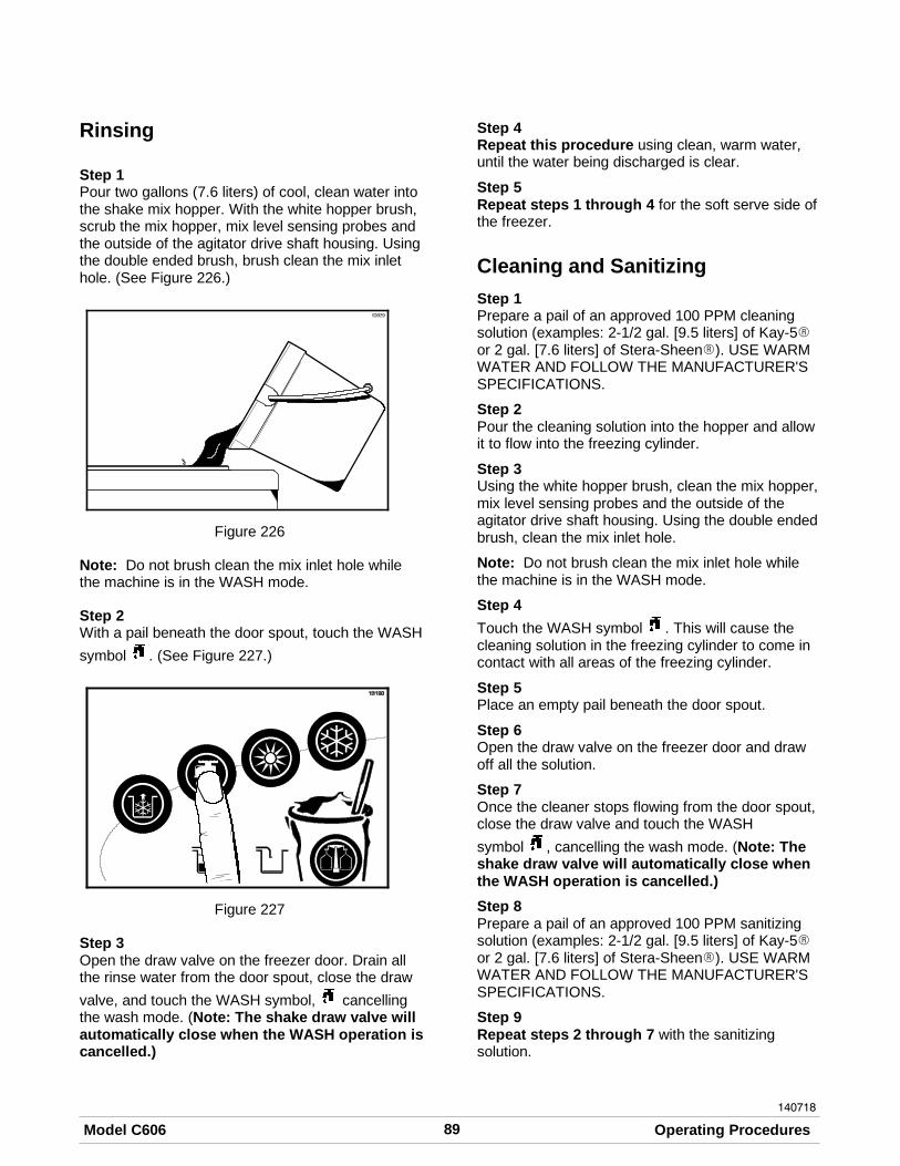
89Model C606 Operating Procedures
140718
Rinsing
Step 1Pour two gallons (7.6 liters) of cool, clean water intothe shake mix hopper. With the white hopper brush,scrub the mix hopper, mix level sensing probes andthe outside of the agitator drive shaft housing. Usingthe double ended brush, brush clean the mix inlethole. (See Figure 226.)
Figure 226
Note: Do not brush clean the mix inlet hole whilethe machine is in the WASH mode.
Step 2With a pail beneath the door spout, touch the WASH
symbol . (See Figure 227.)
Figure 227
Step 3Open the draw valve on the freezer door. Drain allthe rinse water from the door spout, close the draw
valve, and touch the WASH symbol, cancellingthe wash mode. (Note: The shake draw valve willautomatically close when the WASH operation iscancelled.)
Step 4Repeat this procedure using clean, warm water,until the water being discharged is clear.
Step 5Repeat steps 1 through 4 for the soft serve side ofthe freezer.
Cleaning and Sanitizing
Step 1Prepare a pail of an approved 100 PPM cleaningsolution (examples: 2-1/2 gal. [9.5 liters] of Kay-5Ror 2 gal. [7.6 liters] of Stera-SheenR). USE WARMWATER AND FOLLOW THE MANUFACTURER'SSPECIFICATIONS.
Step 2Pour the cleaning solution into the hopper and allowit to flow into the freezing cylinder.
Step 3Using the white hopper brush, clean the mix hopper,mix level sensing probes and the outside of theagitator drive shaft housing. Using the double endedbrush, clean the mix inlet hole.
Note: Do not brush clean the mix inlet hole whilethe machine is in the WASH mode.
Step 4
Touch the WASH symbol . This will cause thecleaning solution in the freezing cylinder to come incontact with all areas of the freezing cylinder.
Step 5Place an empty pail beneath the door spout.
Step 6Open the draw valve on the freezer door and drawoff all the solution.
Step 7Once the cleaner stops flowing from the door spout,close the draw valve and touch the WASH
symbol , cancelling the wash mode. (Note: Theshake draw valve will automatically close whenthe WASH operation is cancelled.)
Step 8Prepare a pail of an approved 100 PPM sanitizingsolution (examples: 2-1/2 gal. [9.5 liters] of Kay-5Ror 2 gal. [7.6 liters] of Stera-SheenR). USE WARMWATER AND FOLLOW THE MANUFACTURER'SSPECIFICATIONS.
Step 9Repeat steps 2 through 7 with the sanitizingsolution.

90 Model C606Operating Procedures
Step 10Repeat steps 1 through 8 for the soft serve side ofthe freezer.
Disassembly - Shake Side
Note: Failure to remove the parts specified belowfor brush cleaning and lubrication will result indamage to the machine. These parts must beremoved every 14 days or the machine will lock outand will not operate.
Step 1Be sure the power switch is in the OFF position.(See Figure 228.)
Figure 228
Step 2Remove the hole plugs from the syrup ports, andremove the restrictor cap from the bottom of thedoor spout.
Step 3Remove the spinner blade from the bottom of thedoor spout by lifting up the locking collar on thespinner coupling and pulling down the blade.
Step 4Remove the handscrews, freezer door, beaterassembly, drive shaft, drive shaft seal, and scraperblades from the freezing cylinder.
Step 5Remove the drive shaft seal from the drive shaft.
Step 6Remove the freezer door o-ring, front bearing,retainer pins, and the draw valve spinner assembly.
Remove the driven spinner from the draw valve bygrasping the draw valve and pulling the drivenspinner out. Remove the spinner shaft seal.(See Figure 229.)
Figure 229
Step 7Remove the two o-rings from the draw valve.
Note: To remove o-rings, use a clean, sanitizedtowel to grasp the o-ring. Apply pressure in anupward direction until the o-ring pops out of itsgroove. With the other hand, push the top of theo-ring forward and it will roll out of the groove andcan easily be removed. If there is more than oneo-ring to be removed, always remove the rear o-ringfirst. This will allow the o-ring to slide over theforward o-rings without falling into the open grooves.
Step 8From the shake pump cylinder, remove the retainingpin, mix inlet adaptor, valve cap, pump gasket, andthe piston. Remove the o-ring from the piston andvalve cap.
Step 9Remove the pump drive shaft from the drive hub inthe rear wall of the mix hopper. (See Figure 230.)
Figure 230

91Model C606 Operating Procedures
050801
Remove the two small o-rings and one large o-ringfrom the pump drive shaft.
Disassembly - Soft Serve Side
Note: Failure to remove the parts specified belowfor brush cleaning and lubrication will result indamage to the machine. These parts must beremoved every 14 days or the machine will lock outand will not operate.
Step 1Be sure the power switch is in the OFF position.
Step 2Remove the handscrews, freezer door, beater,scraper blades, and drive shaft with drive shaft sealfrom the freezing cylinder.
Step 3Remove the scraper blade clips from the scraperblades.
Step 4Remove the drive shaft seal from the drive shaft.
Step 5From the soft serve pump cylinder, remove theretaining pin, mix inlet adaptor, valve cap, pumpgasket, and the piston. Remove the o-ring from thepiston and valve cap.
Step 6Remove the freezer door gasket, front bearing, pivotpin, draw handle, and draw valve. Remove the threeo-rings from the draw valve.
Note: DO NOT attempt to remove the stardesign from the door. The star design is part ofthe door and is NOT a removable piece.
Figure 231
Step 7Remove the pump drive shaft from the drive hub inthe rear wall of the mix hopper. (See Figure 232.)
Figure 232
Remove the two small o-rings and one large o-ringfrom the pump drive shaft.
Step 8Remove the front drip tray and splash shield.Remove the ladles from the two cold toppingcontainers.
Step 9Remove the long drip pan from the front panel. Takeit to the sink for cleaning. (See Figure 233.)
Figure 233

92 Model C606Operating Procedures
Step 10Remove the two short drip pans from the rear panel.Remove the two notched drip pans from the left andright side panels. Take them to the sink for cleaning.(See Figure 234.)
Figure 234
Note: If the drip pans are filled with an excessiveamount of mix, it is an indication that the drive shaftseal(s), or o-ring(s) should be replaced or properlylubricated.
Brush Cleaning
We recommend brush cleaning all the shake parts,then go back and duplicate these steps (where theyapply) for brush cleaning all the soft serve parts. Bydoing so, you will not confuse or interchange theseparts for assembly the next morning. Place the partsin their proper place in the parts tray.
Step 1Prepare a sink with an approved 100 PPM cleaningsolution (examples: Kay-5® or Stera-Sheen®).USE WARM WATER AND FOLLOW THEMANUFACTURER'S SPECIFICATIONS.
Make sure all brushes provided with the freezer areavailable for brush cleaning.
Step 2Thoroughly brush clean all disassembled parts andparts trays in the cleaning solution, making sure alllubricant and mix film is removed. Be sure to brushall surfaces and holes, especially the holes in thepump components and the small syrup holes in theshake freezer door.
Rinse all parts with clean, warm water, one tray at atime, including the tray.
Step 3Return to the freezer with a small amount ofcleaning solution. Using the black brush, clean therear shell bearings at the back of the freezingcylinders. (See Figure 235.)
Figure 235
Step 4Using the black brush, clean the drive hub openingsin the rear wall of the mix hoppers.(See Figure 236.)
Figure 236
Step 5Using the double end brush, brush clean the syrupline fittings.
Step 6Prepare a sink with an approved 100 PPM sanitizingsolution (examples: Kay-5® or Stera-Sheen®).USE WARM WATER AND FOLLOW THEMANUFACTURER'S SPECIFICATIONS.
Step 7Sanitize all parts in the sanitizing solution for aminimum of 1 minute.

93Model C606 Operating Procedures
Step 8Repeat step 3 with the sanitizing solution.
Step 9Place disassembled parts on clean and sanitizedparts trays.
Step 10Wipe all exterior surfaces of the freezer with a clean,sanitized towel.
Step 11Repeat steps 1 through 10 for the soft serve sideof the freezer.
Syrup System - ScheduledMaintenance
Syrup Pump Tube Removal
Step 1Remove the pick up tubes from the syrupcontainers. Wipe the outside of the tubes with aclean, sanitized towel.
For Syrup Bag System: Disconnect the syrup bagfitting from each bag.
Step 2Remove the syrup containers and the pump covertray from inside the cabinet.
Step 3Place the pick up tubes in a pail of an approved 100PPM cleaning solution (examples: Kay-5® orStera-Sheen®). USE WARM WATER ANDFOLLOW THE MANUFACTURER'SSPECIFICATIONS. To avoid contamination, coverthe syrup containers with a plastic wrap.
For Syrup Bag System: Place the syrup hose withthe bag connection fitting in a pail of an approved100 PPM cleaning solution (examples: Kay-5® orStera-Sheen®). USE WARM WATER ANDFOLLOW THE MANUFACTURER'SSPECIFICATIONS.
Step 4Raise the retainer and remove the syrup valve fromthe freezer door. Place the valve in a pail locatedunder the draw valve.
Step 5
Select the CALIBRATION symbol on the controlpanel to display the menu options.
Step 6
Touch the AUTO symbol to move the arrow toSYRUP PRIME. Touch the CALIBRATION symbol
again to display the SYRUP PRIME screen.
Step 7
Select the FLAVOR SELECT symbol for thecorresponding syrup valve to start the flow ofcleaning solution through the syrup line.
Step 8Allow the cleaning solution to flow until all of thesyrup is flushed from the line.
Step 9Once the line is free of syrup, remove the pick uptube from the cleaning solution and continue to runthe pump until the syrup line is free from liquid.
Select the FLAVOR SELECT symbol to stop thepump.
Step 10Repeat steps 3 through 9 using an approved 100PPM sanitizing solution (examples: Kay-5® orStera-Sheen®). USE WARM WATER ANDFOLLOW THE MANUFACTURER'SSPECIFICATIONS.
Step 11Open the pump by pushing up on the hinged cover.(See the arrow in Figure 237.)
Figure 237
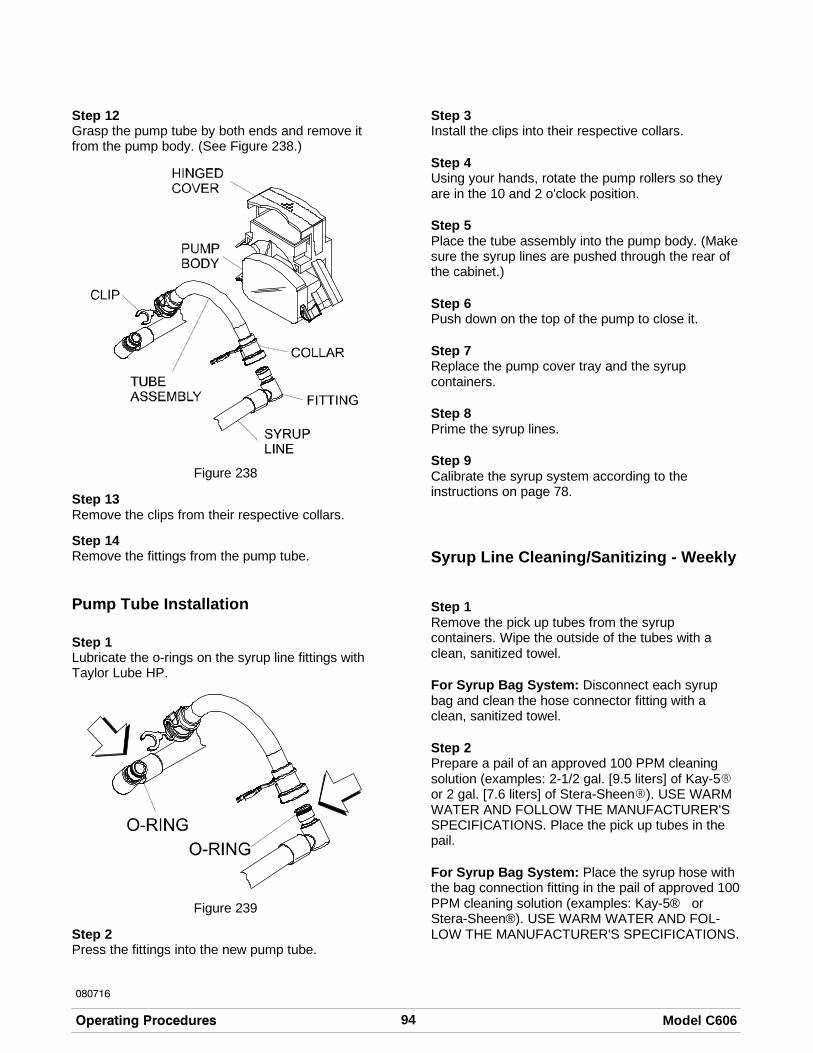
94 Model C606Operating Procedures
080716
Step 12Grasp the pump tube by both ends and remove itfrom the pump body. (See Figure 238.)
Figure 238
Step 13Remove the clips from their respective collars.
Step 14Remove the fittings from the pump tube.
Pump Tube Installation
Step 1Lubricate the o-rings on the syrup line fittings withTaylor Lube HP.
Figure 239
Step 2Press the fittings into the new pump tube.
Step 3Install the clips into their respective collars.
Step 4Using your hands, rotate the pump rollers so theyare in the 10 and 2 o'clock position.
Step 5Place the tube assembly into the pump body. (Makesure the syrup lines are pushed through the rear ofthe cabinet.)
Step 6Push down on the top of the pump to close it.
Step 7Replace the pump cover tray and the syrupcontainers.
Step 8Prime the syrup lines.
Step 9Calibrate the syrup system according to theinstructions on page 78.
Syrup Line Cleaning/Sanitizing - Weekly
Step 1Remove the pick up tubes from the syrupcontainers. Wipe the outside of the tubes with aclean, sanitized towel.
For Syrup Bag System: Disconnect each syrupbag and clean the hose connector fitting with aclean, sanitized towel.
Step 2Prepare a pail of an approved 100 PPM cleaningsolution (examples: 2-1/2 gal. [9.5 liters] of Kay-5Ror 2 gal. [7.6 liters] of Stera-SheenR). USE WARMWATER AND FOLLOW THE MANUFACTURER'SSPECIFICATIONS. Place the pick up tubes in thepail.
For Syrup Bag System: Place the syrup hose withthe bag connection fitting in the pail of approved 100PPM cleaning solution (examples: Kay-5® orStera-Sheen®). USE WARM WATER AND FOL-LOW THE MANUFACTURER'S SPECIFICATIONS.

95Model C606 Operating Procedures
050112
Step 3Raise the retainer and remove the syrup valve fromthe freezer door. Place the valve in a pail locatedunder the draw valve.
Step 4
Select the CALIBRATION symbol on the controlpanel to display the menu options.
Step 5
Touch the AUTO symbol to move the arrow toSYRUP PRIME. Touch the CALIBRATION symbol
again to display the SYRUP PRIME screen.
Step 6
Select the FLAVOR SELECT symbol for thecorresponding syrup valve to start the flow ofcleaning solution through the syrup line.
Step 7Allow the cleaning solution to flow until all the syrupis flushed from the line.
Step 8
Touch the FLAVOR SELECT symbol to stop theflow of cleaning solution.
Step 9Repeat steps 2 - 8 using an approved 100 PPMsanitizing solution (examples: Kay-5® orStera-Sheen®). USE WARM WATER ANDFOLLOW THE MANUFACTURER'SSPECIFICATIONS.
Step 10Remove the syrup nose fitting from the syrup valveby turning the cap counter-clockwise.
Step 11Remove the duckbill valve and the o-ring from thesyrup nose fitting.
Step 12Using the white end of the double-ended brush,scrub the inside of the syrup nose fitting and thesyrup line fitting to remove any residual particles.
Step 13Using a shake cup filled with an approved 100 PPMsanitizing solution, rinse the syrup valve fittingthoroughly.
Step 14Using a clean, sanitized towel, gently wipe any syrupfrom the duckbill valve.
Step 15Install the duckbill valve into the syrup nose fitting,with the flat end aligned with the open slot in thesyrup nose fitting.
Note: Replace the duckbill valve if it is damaged orextends past the syrup nose fitting slot.(See Figure 181.)
Figure 240
Step 16Install the syrup nose fitting onto the syrup linefitting. Tighten by hand until snug.
Note: The duckbill valve must be wet when thesyrup nose fitting is assembled on the syrup linefitting. The sanitized water will lubricate the bottomflat surface and prevent the duckbill from twistingwhen the the syrup nose fitting is tightened.
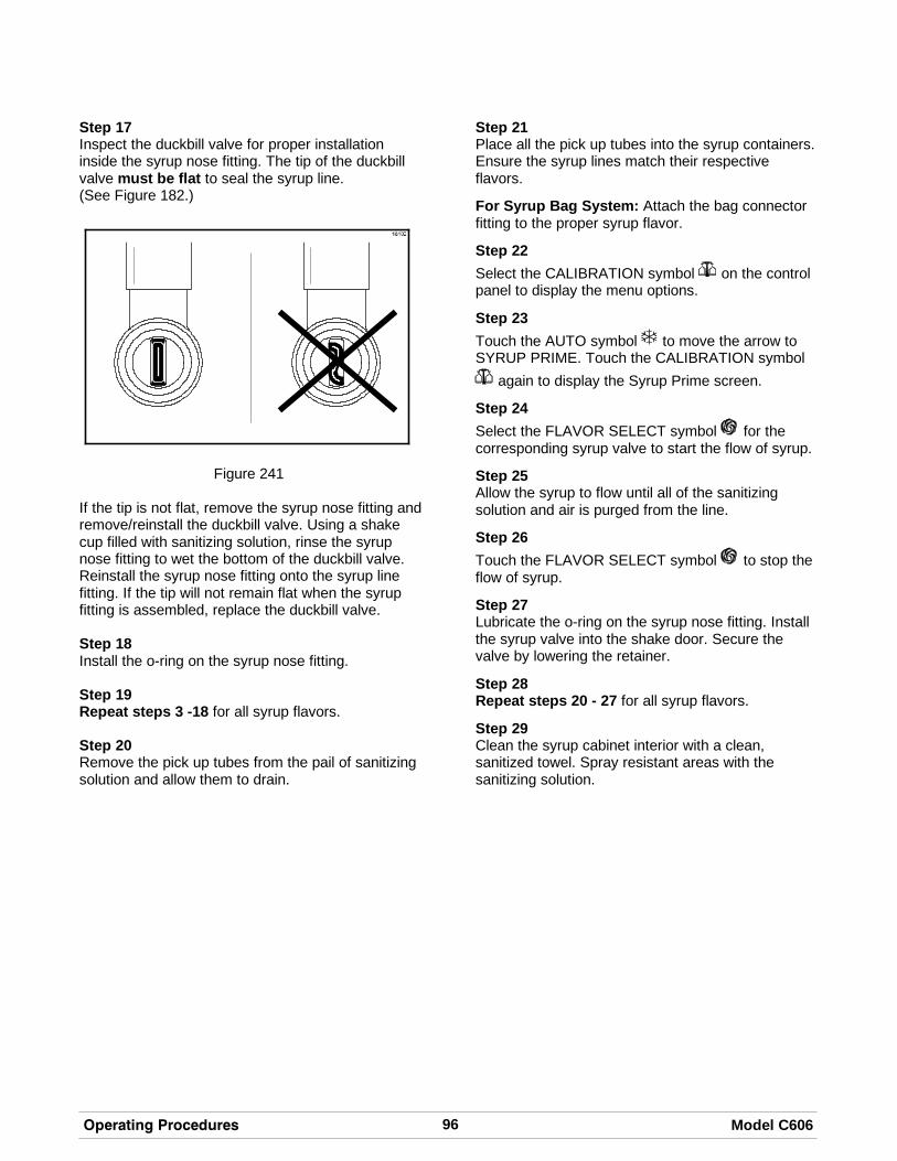
96 Model C606Operating Procedures
Step 17Inspect the duckbill valve for proper installationinside the syrup nose fitting. The tip of the duckbillvalve must be flat to seal the syrup line.(See Figure 182.)
Figure 241
If the tip is not flat, remove the syrup nose fitting andremove/reinstall the duckbill valve. Using a shakecup filled with sanitizing solution, rinse the syrupnose fitting to wet the bottom of the duckbill valve.Reinstall the syrup nose fitting onto the syrup linefitting. If the tip will not remain flat when the syrupfitting is assembled, replace the duckbill valve.
Step 18Install the o-ring on the syrup nose fitting.
Step 19Repeat steps 3 -18 for all syrup flavors.
Step 20Remove the pick up tubes from the pail of sanitizingsolution and allow them to drain.
Step 21Place all the pick up tubes into the syrup containers.Ensure the syrup lines match their respectiveflavors.
For Syrup Bag System: Attach the bag connectorfitting to the proper syrup flavor.
Step 22
Select the CALIBRATION symbol on the controlpanel to display the menu options.
Step 23
Touch the AUTO symbol to move the arrow toSYRUP PRIME. Touch the CALIBRATION symbol
again to display the Syrup Prime screen.
Step 24
Select the FLAVOR SELECT symbol for thecorresponding syrup valve to start the flow of syrup.
Step 25Allow the syrup to flow until all of the sanitizingsolution and air is purged from the line.
Step 26
Touch the FLAVOR SELECT symbol to stop theflow of syrup.
Step 27Lubricate the o-ring on the syrup nose fitting. Installthe syrup valve into the shake door. Secure thevalve by lowering the retainer.
Step 28Repeat steps 20 - 27 for all syrup flavors.
Step 29Clean the syrup cabinet interior with a clean,sanitized towel. Spray resistant areas with thesanitizing solution.

97Model C606 Important: Operator Checklist
051207
Section 7 Important: Operator Checklist
During Cleaning and Sanitizing
ALWAYS FOLLOW LOCAL HEALTH CODES.
Cleaning and sanitizing schedules are governed byyour State or local regulatory agencies and must befollowed accordingly. The following check pointsshould be stressed during the cleaning andsanitizing operations.
CLEANING AND SANITIZING MUST BEPERFORMED EVERY TWO WEEKS.
Troubleshooting Bacterial Count
j 1. Thoroughly clean and sanitize the machineregularly, including complete disassembly andbrush cleaning.
j 2. Use all brushes supplied for thoroughcleaning. The brushes are specially designedto reach all mix passageways.
j 3. Use the white bristle brush to clean the mixinlet hole which extends from the mix hopperdown to the rear of the freezing cylinder.
j 4. Use the black bristle brush to thoroughlyclean the rear shell bearing located at the rearof the freezing cylinder and the drive hubopening in the rear wall of the mix hopper. Besure there is a generous amount of cleaningsolution on the brush.
j 5. Properly prepare the cleaning and sanitizingsolutions. Read and follow the label directionscarefully. Too strong of a solution maydamage the parts and too weak of a solutionwill not do an adequate job of cleaning orsanitizing.
j 6. The temperature of the mix in the mix hopperand walk-in cooler should be below 40_F.(4.4_C.).
j 7. Discard remaining mix from the freezer during“Closing Procedures”.
Regular Maintenance Checks
j 1. Replace scraper blades that are nicked ordamaged. Before installing the beaterassembly, be certain that scraper blades areproperly attached to the helix.
j 2. Check the rear shell bearing for signs of wear(excessive mix leakage in rear drip pan) andbe certain it is properly cleaned.
j 3. Using a screwdriver and cloth towel, keep therear shell bearing and the female hex drivesocket clean and free of lubricant and mixdeposits.
j 4. Dispose of o-rings and seals if they are worn,torn, or fit too loosely, and replace with newones.
j 5. Follow all lubricating procedures as outlined in“Assembly”.
j 6. If your machine is air cooled, check thecondensers for accumulation of dirt and lint.Dirty condensers will reduce the efficiencyand capacity of the machine. Condensersshould be cleaned monthly with a soft brush.Never use screwdrivers or other metal probesto clean between the fins.Note: For machines equipped with an airfilter, it will be necessary to vacuum clean thefilters on a monthly schedule.
Caution: Always disconnectelectrical power prior to cleaning thecondenser. Failure to follow this instructionmay result in electrocution.
j 7. If your machine is water cooled, check thewater lines for kinks or leaks. Kinks can occurwhen the machine is moved back and forth forcleaning or maintenance purposes.Deteriorated or cracked water lines should bereplaced only by an authorized Taylordistributor.

98 Model C606Important: Operator Checklist
080327
Winter Storage
If the place of business is to be closed during thewinter months, it is important to protect the freezerby following certain precautions, particularly if thebuilding is subject to freezing conditions.
Disconnect the freezer from the main power sourceto prevent possible electrical damage.
On water cooled freezers, disconnect the watersupply. Relieve pressure on the spring in the watervalve. Use air pressure on the outlet side to blow outany water remaining in the condenser. This isextremely important. Failure to follow thisprocedure may cause severe and costly damage tothe refrigeration system.
Your local Taylor Distributor can perform this winterstorage service for you.
Wrap detachable parts of the freezer such asbeater, blades, drive shaft, and freezer door, andplace them in a protected dry place. Rubber trimparts and gaskets can be protected by wrappingthem with moisture-proof paper. All parts should bethoroughly cleaned of dried mix or lubrication whichattract mice and other vermin.
Note: It is recommended that an authorized servicetechnician perform winter storage draining, to insureall water has been removed. This will guard againstfreezing and rupturing of the components.

Section 8 Troubleshooting Guide
99Model C606 Troubleshooting Guide
PR
OB
LE
MS
HA
KE
SID
EP
RO
BA
BL
EC
AU
SE
SO
FT
SE
RV
ES
IDE
PR
OB
AB
LE
CA
US
EE
ITH
ER
SID
EP
RO
BA
BL
EC
AU
SE
RE
ME
DY
PA
GE
RE
F.
1.S
oft
lock
mes
sage
appe
ars
ondi
spla
y.
a.A
neq
uipm
ent
faul
tha
soc
curr
ed.
a.D
eter
min
ere
ason
the
failu
reoc
curr
ed.
Cor
rect
caus
efo
rfa
ilure
,th
ense
lect
HE
AT
sym
bolt
ost
art
ahe
atcy
cle
orW
AS
Hto
disa
ssem
ble
and
brus
hcl
ean
the
mac
hine
.
36
b.M
ore
than
24ho
urs
sinc
eth
ela
stH
EA
Tcy
cle.
b.T
hefr
eeze
rm
ust
goth
roug
ha
HE
AT
cycl
eev
ery
24ho
urs.
The
free
zer
mus
tno
wbe
disa
ssem
bled
and
brus
hcl
eane
dor
plac
edin
ahe
atcy
cle.
36
c.T
hepo
wer
switc
his
inth
eO
FF
posi
tion.
c.T
hepo
wer
switc
hm
ust
bein
the
ON
posi
tion.
The
free
zer
mus
tno
wbe
disa
ssem
bled
and
brus
hcl
eane
dor
plac
edin
ahe
atcy
cle.
36
d.T
hefr
eeze
ris
not
inth
eA
UT
Oor
ST
AN
DB
Ym
ode
whe
nth
ehe
atcy
cle
was
prog
ram
med
tost
art.
d.T
hefr
eeze
rm
ust
bein
the
AU
TO
orS
TA
ND
BY
mod
e.T
hefr
eeze
rm
ust
now
bedi
sass
embl
edan
dbr
ush
clea
ned
orpl
aced
ina
heat
cycl
e.
36

100Troubleshooting Guide Model C606
PR
OB
LE
MP
AG
ER
EF
.R
EM
ED
YE
ITH
ER
SID
EP
RO
BA
BL
EC
AU
SE
SO
FT
SE
RV
ES
IDE
PR
OB
AB
LE
CA
US
ES
HA
KE
SID
EP
RO
BA
BL
EC
AU
SE
1.S
oft
lock
mes
sage
appe
ars
ondi
spla
y.(C
ontin
ued)
e.M
ixou
tco
nditi
on.
e.T
hele
velo
fm
ixin
the
mix
hopp
erm
ust
beup
toth
efil
llev
elin
dica
tor
onth
eag
itato
rpa
ddle
.T
hefr
eeze
rm
ust
now
bedi
sass
embl
edan
dbr
ush
clea
ned,
orpl
aced
ina
heat
cycl
e.
36
f.T
heag
itato
ris
not
inst
alle
d.f.
The
agita
tor
mus
tbe
clea
ned
and
inst
alle
dbe
fore
star
ting
the
HE
AT
cycl
e.T
hefr
eeze
rm
ust
now
bedi
sass
embl
edan
dbr
ush
clea
ned
orpl
aced
ina
heat
cycl
e.
69
/7
2
2.H
ard
lock
mes
sage
appe
ars
ondi
spla
y.
a.B
rush
clea
nin
terv
alex
ceed
ed.
a.T
hefr
eeze
rm
ust
bedi
sass
embl
edan
dbr
ush
clea
ned
with
in24
hour
sw
hen
the
coun
ter
indi
cate
son
eda
yre
mai
ning
.
35
b.A
barr
elor
hopp
erth
erm
isto
ris
faul
ty.
b.C
alla
nau
thor
ized
serv
ice
tech
nici
an.
--
-

101Model C606 Troubleshooting Guide
PR
OB
LE
MP
AG
ER
EF
.R
EM
ED
YE
ITH
ER
SID
EP
RO
BA
BL
EC
AU
SE
SO
FT
SE
RV
ES
IDE
PR
OB
AB
LE
CA
US
ES
HA
KE
SID
EP
RO
BA
BL
EC
AU
SE
3.N
opr
oduc
tis
bein
gdi
spen
sed.
a.Lo
won
mix
.T
heM
IXO
UT
light
ison
.a.
Add
mix
toth
em
ixho
pper
.R
etur
nto
AU
TO
mod
e.
67
/6
8
b.T
hepo
wer
switc
his
inth
eO
FF
posi
tion.
b.P
lace
the
pow
ersw
itch
toO
Nan
dse
lect
AU
TO
.6
4
c.M
achi
neno
tin
AU
TO
mod
e.c.
Sel
ect
AU
TO
and
allo
wm
achi
neto
cycl
eof
fbe
fore
draw
ing
prod
uct.
68
d.B
eate
rm
otor
isou
ton
rese
t,B
EA
TE
RO
VE
RLO
AD
mes
sage
disp
laye
d.
d.C
alla
nau
thor
ized
serv
ice
tech
nici
an.
--
-
e.T
hepu
mp
mot
oris
not
runn
ing
inth
eA
UT
Om
ode.
e.P
ush
the
pum
pre
set
butt
on.
Che
ckpu
mp
mot
oris
oper
atin
gw
hen
the
draw
valv
eis
rais
ed.
32
f.F
reez
e-up
inm
ixin
let
hole
.f.
Cal
lan
auth
oriz
edse
rvic
ete
chni
cian
.-
--
g.T
hem
ixpu
mp
ball
cran
kis
brok
en.
g.C
alla
nau
thor
ized
serv
ice
tech
nici
an.
--
-
h.F
eed
tube
orch
eck
ring
not
prop
erly
inst
alle
d.
h.M
ake
sure
feed
tube
and
rubb
erch
eck
ring
are
prop
erly
inst
alle
d.
62
i.M
enu
isdi
spla
yed
mak
ing
flavo
rse
lect
keys
inop
erat
ive.
i.E
xit
the
men
uby
mov
ing
the
curs
orar
row
to“E
XIT
”an
dto
uchi
ngth
eC
AL
sym
bol.
Thi
sw
illre
stor
eth
eco
ntro
lkey
sto
thei
rno
rmal
func
tion.
78

102Troubleshooting Guide Model C606
PR
OB
LE
MP
AG
ER
EF
.R
EM
ED
YE
ITH
ER
SID
EP
RO
BA
BL
EC
AU
SE
SO
FT
SE
RV
ES
IDE
PR
OB
AB
LE
CA
US
ES
HA
KE
SID
EP
RO
BA
BL
EC
AU
SE
3.N
opr
oduc
tis
bein
gdi
spen
sed.
(Con
tinue
d)
j.D
raw
valv
eno
top
enin
g.j.
Dra
wva
lve
not
alig
ned
with
actu
ator
brac
ket
whe
nfr
eeze
rdo
orin
stal
led.
Rea
ssem
ble
with
corr
ect
alig
nmen
t.
55
4.T
hepr
oduc
tis
too
soft
.a.
Too
muc
hsy
rup
-1
floz
(30
ml)
in5
seco
nds.
For
Trip
leT
hick
Sha
keS
yrup
:1
oz(3
0m
l)±1
1/8
oz(4
ml)
in7
seco
nds.
a.C
alib
rate
the
syru
ps.
78
b.D
raw
rate
isse
tto
ofa
st.
b.A
djus
tdr
awra
teof
5to
71/
2oz
.(1
42g.
to21
3g.
)of
prod
uct
byw
eigh
tin
10se
cond
s.
78
5.T
hepr
oduc
tis
too
thic
k.a.
Not
enou
ghsy
rup
-1
floz
(30
ml)
in5
seco
nds.
For
Trip
leT
hick
Sha
keS
yrup
:1
oz(3
0m
l)±
1/8
oz(4
ml)
in7
seco
nds.
a.C
alib
rate
the
syru
ps.
Che
ckth
atth
esy
rup
cont
aine
rsar
eno
tem
pty.
78
b.F
reez
ing
cylin
der
not
prim
edco
rrec
tly.
b.D
rain
the
free
zing
cylin
der
and
repr
ime
the
mac
hine
.6
7/
68
c.A
ir/m
ixpu
mp
inco
rrec
tlyas
sem
bled
.
c.F
ollo
was
sem
bly
proc
edur
esca
refu
lly.
60
d.T
hevi
scos
ityco
ntro
lis
set
too
cold
.d.
Cal
lan
auth
oriz
edse
rvic
ete
chni
cian
.-
--
e.F
reez
e-up
inm
ixin
let
hole
.e.
Cal
lan
auth
oriz
edse
rvic
ete
chni
cian
.-
--

103Model C606 Troubleshooting Guide
PR
OB
LE
MP
AG
ER
EF
.R
EM
ED
YE
ITH
ER
SID
EP
RO
BA
BL
EC
AU
SE
SO
FT
SE
RV
ES
IDE
PR
OB
AB
LE
CA
US
ES
HA
KE
SID
EP
RO
BA
BL
EC
AU
SE
6.T
hem
ixin
the
hopp
eris
too
war
m.
a.H
oppe
rco
ver
isno
tin
posi
tion.
a.C
lean
and
sani
tize
hopp
erco
ver
and
plac
ein
posi
tion.
68
b.T
heag
itato
ris
not
inst
alle
d.b.
Cle
anan
dsa
nitiz
eth
eag
itato
ran
din
stal
l.6
5/
67
c.T
heho
pper
tem
pera
ture
isou
tof
adju
stm
ent.
c.C
alla
nau
thor
ized
serv
ice
tech
nici
an.
--
-
7.T
hem
ixin
the
hopp
eris
too
cold
.
a.T
heho
pper
tem
pera
ture
isou
tof
adju
stm
ent.
a.C
alla
nau
thor
ized
serv
ice
tech
nici
an.
--
-
8.M
ixLo
wan
dM
ixO
utpr
obes
are
not
func
tioni
ng.
a.M
ilkst
one
build
-up
inth
eho
pper
.a.
Cle
anho
pper
sth
orou
ghly
.9
2
9.P
rodu
ctis
colle
ctin
gon
top
ofth
edr
awva
lve.
a.In
adeq
uate
lubr
icat
ion
ofsp
inne
rsh
aft
orse
al.
a.Lu
bric
ate
prop
erly
.5
3
b.S
pinn
ersh
aft
seal
ism
issi
ngor
wor
n.b.
Inst
allo
rre
plac
eth
esp
inne
rsh
aft
seal
.5
3
10.P
rodu
ctis
colle
ctin
gon
top
ofth
efr
eeze
rdo
or.
a.T
heto
po-
ring
ondr
awva
lve
isim
prop
erly
lubr
icat
edor
wor
n.
a.Lu
bric
ate
prop
erly
orre
plac
eth
eo-
ring.
53
/5
8
11.E
xces
sive
mix
leak
age
from
the
bott
omof
door
spou
t.
a.B
otto
mo-
ring
ondr
awva
lve
isim
prop
erly
lubr
icat
edor
wor
n.
a.Lu
bric
ate
prop
erly
orre
plac
eth
eo-
ring.
53
/5
8

104Troubleshooting Guide Model C606
PR
OB
LE
MP
AG
ER
EF
.R
EM
ED
YE
ITH
ER
SID
EP
RO
BA
BL
EC
AU
SE
SO
FT
SE
RV
ES
IDE
PR
OB
AB
LE
CA
US
ES
HA
KE
SID
EP
RO
BA
BL
EC
AU
SE
12.E
xces
sive
mix
leak
age
into
the
long
drip
pan.
a.T
hese
alon
driv
esh
aft
isim
prop
erly
lubr
icat
edor
wor
n.
a.Lu
bric
ate
prop
erly
orre
plac
eth
ese
al.
52
/5
6
b.T
hese
alis
inst
alle
din
side
-out
onth
edr
ive
shaf
t.
b.In
stal
lcor
rect
ly.
52
/5
6
c.In
adeq
uate
lubr
icat
ion
ofth
edr
ive
shaf
t.
c.Lu
bric
ate
prop
erly
.5
2/
56
d.T
hedr
ive
shaf
tan
dbe
ater
asse
mbl
yw
ork
forw
ard.
d.C
alla
nau
thor
ized
serv
ice
tech
nici
an.
--
-
e.W
orn
rear
shel
lbe
arin
g.e.
Cal
lan
auth
oriz
edse
rvic
ete
chni
cian
.-
--
f.G
ear
box
out
ofal
ignm
ent.
f.C
alla
nau
thor
ized
serv
ice
tech
nici
an.
--
-
13.T
hedr
ive
shaf
tis
stuc
kin
the
driv
eco
uplin
g.
a.M
ixan
dlu
bric
ant
colle
cted
indr
ive
coup
ling.
a.B
rush
clea
nth
ere
arsh
ell
bear
ing
area
regu
larly
.9
2
b.R
ound
edco
rner
sof
driv
esh
aft,
driv
eco
uplin
g,or
both
.
b.C
alla
nau
thor
ized
serv
ice
tech
nici
an.
--
-
c.G
ear
box
isou
tof
alig
nmen
t.c.
Cal
lan
auth
oriz
edse
rvic
ete
chni
cian
.-
--

105Model C606 Troubleshooting Guide
PR
OB
LE
MP
AG
ER
EF
.R
EM
ED
YE
ITH
ER
SID
EP
RO
BA
BL
EC
AU
SE
SO
FT
SE
RV
ES
IDE
PR
OB
AB
LE
CA
US
ES
HA
KE
SID
EP
RO
BA
BL
EC
AU
SE
14.T
hefr
eezi
ngcy
linde
rw
alls
are
scor
ed.
a.M
issi
ngor
wor
nfr
ont
bear
ing.
a.In
stal
lor
repl
ace
the
fron
tbe
arin
g.5
5
b.M
issi
ngor
wor
nfr
ont
bear
ing
and
beat
ersh
oes.
b.In
stal
lor
repl
ace
the
fron
tbe
arin
gan
dbe
ater
shoe
s.5
8
c.D
amag
edsc
rape
rbl
ades
and/
orcl
ips.
c.R
epla
cesc
rape
rbl
ades
and/
orcl
ips.
57
d.B
roke
nfr
eeze
rdo
orba
ffle
rod.
d.R
epla
cefr
eeze
rdo
or.
59
e.S
aniti
zing
solu
tion
was
still
inth
efr
eezi
ngcy
linde
rw
hen
unit
was
plac
edin
AU
TO
.
e.U
nit
mus
tN
OT
bepl
aced
inA
UT
Odu
ring
sani
tizin
g.P
lace
inA
UT
Oon
lyaf
ter
unit
has
been
prim
edan
dal
lsan
itizi
ngso
lutio
nha
sbe
enre
mov
ed.
64
/6
6
f.B
roke
nbe
ater
pins
.f.
Rep
lace
beat
eras
sem
bly.
53
/5
7
g.B
eate
ras
sem
bly
isbe
nt.
g.R
epla
cebe
ater
asse
mbl
y.5
3/
57
h.G
ear
box
isou
tof
alig
nmen
t.h.
Cal
lan
auth
oriz
edse
rvic
ete
chni
cian
.-
--
15.T
hepr
oduc
tm
akes
apo
ppin
gso
und
whe
ndr
awn.
a.D
raw
rate
isse
tto
ofa
st.
a.A
djus
tdr
awra
teof
5to
71/
2oz
.(1
42g.
to21
3g.
)of
prod
uct
byw
eigh
tin
10se
cond
s.
59
b.P
ump
asse
mbl
edin
corr
ectly
.b.
Ass
embl
ean
dlu
bric
ate
acco
rdin
gto
inst
ruct
ions
inth
ism
anua
l.
60
c.F
reez
ing
cylin
der
not
prim
edco
rrec
tly.
c.D
rain
the
free
zing
cylin
der
and
repr
ime
the
mac
hine
.6
7/
68

106Troubleshooting Guide Model C606
PR
OB
LE
MP
AG
ER
EF
.R
EM
ED
YE
ITH
ER
SID
EP
RO
BA
BL
EC
AU
SE
SO
FT
SE
RV
ES
IDE
PR
OB
AB
LE
CA
US
ES
HA
KE
SID
EP
RO
BA
BL
EC
AU
SE
16.N
oco
ntro
lpa
nel
func
tions
with
pow
ersw
itch
ON
.
a.M
achi
neis
unpl
ugge
d.a.
Plu
gin
tow
allr
ecep
tacl
e.-
--
b.C
ircui
tbr
eake
rO
FF
orbl
own
fuse
.b.
Tur
nth
ebr
eake
rO
Nor
repl
ace
the
fuse
.-
--
17.T
hedr
awva
lve
isno
top
enin
g.
a.T
hepo
wer
switc
his
off.
a.P
lace
the
pow
ersw
itch
inth
eO
Npo
sitio
n.3
6
b.T
hesh
ake
side
isin
the
ST
AN
DB
Ym
ode.
b.C
ance
lthe
ST
AN
DB
Ym
ode.
43
c.A
heat
cycl
eis
inpr
ogre
ss.
c.W
ait
for
the
com
plet
ion
ofth
ehe
attr
eatm
ent
cycl
e.3
5
d.T
hem
enu
isdi
spla
yed,
mak
ing
the
flavo
rse
lect
keys
inop
erat
ive.
d.E
xit
the
men
uby
mov
ing
the
curs
orar
row
to“E
XIT
”an
dto
uchi
ngth
eC
AL
sym
bol.
Thi
sw
illre
stor
eth
eco
ntro
lkey
sto
thei
rno
rmal
func
tion.
78
e.T
hedr
awva
lve
was
n't
alig
ned
with
the
actu
ator
brac
ket
whe
nth
efr
eeze
rdo
orw
asin
stal
led.
e.R
eass
embl
ew
ithth
eco
rrec
tal
ignm
ent.
Tig
hten
the
hand
scre
ws
ina
cris
s-cr
oss
patt
ern
whe
nin
stal
ling
the
free
zer
door
.
55
f.T
hedr
awva
lve
was
not
lubr
icat
ed.
f.Lu
bric
ate
the
draw
valv
ean
do'
rings
.5
3
g.T
hesh
ake
actu
ator
asse
mbl
yis
out
ofal
ignm
ent
oris
mal
func
tioni
ng.
g.C
alla
nau
thor
ized
serv
ice
tech
nici
an.
--
-

107Model C606 Troubleshooting Guide
PR
OB
LE
MP
AG
ER
EF
.R
EM
ED
YE
ITH
ER
SID
EP
RO
BA
BL
EC
AU
SE
SO
FT
SE
RV
ES
IDE
PR
OB
AB
LE
CA
US
ES
HA
KE
SID
EP
RO
BA
BL
EC
AU
SE
18.T
hedr
awva
lve
isno
tcl
osin
g.
a.T
hedr
awva
lve
was
not
alig
ned
with
the
actu
ator
brac
ket
whe
nth
efr
eeze
rdo
orw
asin
stal
led.
a.R
eass
embl
ew
ithth
eco
rrec
tal
ignm
ent.
Tig
hten
the
hand
scre
ws
ina
cris
s-cr
oss
patt
ern
whe
nin
stal
ling
the
free
zer
door
.
55
b.T
hedr
awva
lve
was
not
lubr
icat
ed.
b.Lu
bric
ate
the
draw
valv
ean
do'
rings
.5
3
c.T
hesp
inne
rsh
aft
was
not
lubr
icat
ed.
c.Lu
bric
ate
the
spin
ner
shaf
t.5
3
d.T
hesp
inne
rbl
ade
beca
me
dise
ngag
edfr
omth
edr
iven
spin
ner
whe
nth
edr
awva
lve
was
rais
ed.
d.C
alla
nau
thor
ized
serv
ice
tech
nici
anto
chec
kth
esp
inne
rco
uplin
gpo
sitio
non
the
mot
or.
--
-
e.T
hepr
oduc
tis
too
thic
k.e.
Che
ckth
atth
epr
oduc
tte
mpe
ratu
reis
with
insp
ecifi
catio
n.(S
eepr
oble
m“P
rodu
ctT
ooT
hick
”on
page
102.
)
--
-
f.T
hesh
ake
actu
ator
asse
mbl
yis
out
ofal
ignm
ent
oris
mal
func
tioni
ng.
f.C
alla
nau
thor
ized
serv
ice
tech
nici
an.
--
-
19.T
hem
ixpu
mp
will
not
oper
ate
inth
eP
UM
Pm
ode.
a.P
ump
mot
oris
not
runn
ing.
a.P
ush
the
pum
pre
set
butt
on.
32

108Troubleshooting Guide Model C606
PR
OB
LE
MP
AG
ER
EF
.R
EM
ED
YE
ITH
ER
SID
EP
RO
BA
BL
EC
AU
SE
SO
FT
SE
RV
ES
IDE
PR
OB
AB
LE
CA
US
ES
HA
KE
SID
EP
RO
BA
BL
EC
AU
SE
20.T
hem
ixpu
mp
runs
cons
tant
lyin
the
AU
TO
mod
e.
a.D
raw
valv
eis
not
fully
clos
ed.
a.R
aise
draw
hand
leso
draw
valv
eis
clos
edal
lth
ew
ay.
68
21.S
yrup
cann
otbe
calib
rate
dor in
cons
iste
ntca
libra
tion
read
ings
.
a.T
hepu
mp
tube
has
colla
psed
.a.
Rep
lace
pum
ptu
be.
93
b.S
yrup
tem
pera
ture
too
cold
.b.
Allo
wth
esy
rup
tow
arm
upbe
fore
usin
g.N
ote
:N
ever
refr
iger
ate
the
syru
p.
Kee
pa
repl
acem
ent
cont
aine
rne
arth
esh
ake
mac
hine
loca
tion
soth
esy
rup
tem
pera
ture
can
stab
ilize
befo
reus
e.
80
c.T
hick
syru
pin
bott
omof
cont
aine
r.c.
Sha
kew
ellb
efor
eus
e.8
0
d.S
yrup
leak
.d.
Insp
ect
syru
psy
stem
for
leak
s.-
--
e.S
yrup
lines
are
not
mat
ched
with
the
syru
pfla
vor
orar
eno
tpr
oper
lyco
nnec
ted.
e.M
atch
the
colo
rof
the
syru
ppi
ck-u
ptu
bean
dca
pw
ithth
eco
rrec
tsy
rup
cont
aine
r.M
ake
sure
the
tube
ispr
oper
lyco
nnec
ted.
96
f.P
lugg
edsy
rup
line
fittin
gat
free
zer
door
conn
ectio
n.
f.C
lean
the
syru
plin
efit
ting.
80
g.T
hepi
ck-u
ptu
beis
pinc
hed
orki
nked
.g.
Adj
ust
the
line
rout
ing
soth
atit
isno
tpi
nche
dor
kink
ed.
80

109Model C606 Troubleshooting Guide
PR
OB
LE
MP
AG
ER
EF
.R
EM
ED
YE
ITH
ER
SID
EP
RO
BA
BL
EC
AU
SE
SO
FT
SE
RV
ES
IDE
PR
OB
AB
LE
CA
US
ES
HA
KE
SID
EP
RO
BA
BL
EC
AU
SE
21.S
yrup
cann
otbe
calib
rate
dor
has
inco
nsis
tent
calib
ratio
nre
adin
gs.
(Con
tinue
d)
h.T
hesy
rup
line
ispl
ugge
dor
rest
ricte
d.h.
Flu
shan
dsa
nitiz
eth
esy
rup
lines
.C
lean
the
syru
psy
stem
wee
kly.
Do
not
atta
chth
esh
ort
syru
plin
eto
the
door
whe
nth
elin
eis
not
prim
edw
ithsy
rup.
94
i.A
irin
syru
plin
e.i.
Fol
low
syru
plin
epr
imin
gpr
oced
ure
tore
mov
eai
rfr
omlin
e.
80
j.A
irin
take
line
topu
mp
will
not
hold
syru
ppr
ime.
j.Lu
bric
ate
pum
ptu
befit
ting
o-rin
gs.
Insp
ect
the
inta
kelin
efo
rle
aks.
94
22.S
yrup
cont
inue
sto
flow
afte
rdr
awin
ga
shak
e.
a.A
irin
syru
plin
e.a.
Fol
low
syru
ppr
ime
proc
edur
e.8
0
b.D
uckb
illva
lve
dam
aged
.b.
Rem
ove
syru
pno
sefit
ting
and
clea
n.R
epla
cedu
ckbi
llva
lve.
95
23.S
pinn
ersh
aft
will
not
rota
teto
blen
dm
ixan
dsy
rup.
a.F
lexi
ble
coup
ling
isbr
oken
.a.
Cal
lan
auth
oriz
edse
rvic
ete
chni
cian
.-
--
b.P
inis
mis
sing
inqu
ick
disc
onne
ctof
spin
ner
coup
ling.
b.C
alla
nau
thor
ized
serv
ice
tech
nici
an.
--
-
c.S
pinn
erm
otor
isou
ton
ther
mal
over
load
.c.
Allo
wth
esp
inne
rm
otor
toco
ol.
Che
cklu
bric
atio
non
the
spin
ner
shaf
t.
53

110Troubleshooting Guide Model C606
PR
OB
LE
MP
AG
ER
EF
.R
EM
ED
YE
ITH
ER
SID
EP
RO
BA
BL
EC
AU
SE
SO
FT
SE
RV
ES
IDE
PR
OB
AB
LE
CA
US
ES
HA
KE
SID
EP
RO
BA
BL
EC
AU
SE
24.S
yrup
topp
ings
are
not
hot.
a.T
oppi
nghe
ater
sar
eno
tO
N.
a.S
elec
tto
ppin
ghe
ater
sym
bols
.S
ymbo
lsw
illbe
litw
hen
heat
ers
are
ON
.
73
b.N
ow
ater
isin
topp
ing
wel
l.b.
Fill
toin
dica
ting
mar
k.7
3
c.T
hew
ater
isno
tho
ten
ough
.c.
Usi
nga
ther
mom
eter
,ch
eck
the
wat
erte
mpe
ratu
rein
the
topp
ing
wel
l.It
shou
ldbe
140_
F(6
0_C
).
--
-

111Model C606 Parts Replacement Schedule
Section 9 Parts Replacement Schedule
PART DESCRIPTION EVERY 3 MONTHS EVERY 6 MONTHS ANNUALLY
Scraper Blade-Shake X
Scraper Blade-Soft Serve X
Drive Shaft Seal X
Freezer Door O-Ring-Shake X
Freezer Door Gasket-Soft Serve X
Front Bearing X
Front Beater Shoes-Soft Serve X
Draw Valve O-Ring X
Spinner Shaft Seal-Shake X
Restrictor Cap-Shake X
Mix Feed Tube O-Ring X
Pump O-Ring X
Pump Valve Gasket X
Mix Feed Tube Check Ring X
Pump Drive Shaft O-Ring X
Syrup Valve-Duckbill X
Peristaltic Pump Tubes Inspect & Replace if Necessary
White Bristle Brush, 3” x 7” Inspect & Replace if Necessary Minimum
White Bristle Brush, 3” x 1/2” Inspect & Replace if Necessary Minimum
White Bristle Brush, 1-1/2” x 3” Inspect & Replace if Necessary Minimum
White Bristle Brush, 1” x 2” Inspect & Replace if Necessary Minimum
Black Bristle Brush, 1” x 2” Inspect & Replace if Necessary Minimum
Double-Ended Brush Inspect & Replace if Necessary Minimum
Yellow Bristle Brush Inspect & Replace if Necessary Minimum
Brush Set (3) Inspect & Replace if Necessary Minimum

112 Model C606Limited Warranty on Equipment
131125
Section 10 Limited Warranty on Equipment
TAYLOR COMPANY LIMITED WARRANTY ON FREEZERS
Taylor Company, a division of Carrier Commercial Refrigeration, Inc. (“Taylor”) is pleased to provide this limitedwarranty on new Taylor-branded freezer equipment available from Taylor to the market generally (the “Product”)to the original purchaser only.
LIMITED WARRANTY
Taylor warrants the Product against failure due to defect in materials or workmanship under normal use andservice as follows. All warranty periods begin on the date of original Product installation. If a part fails due todefect during the applicable warranty period, Taylor, through an authorized Taylor distributor or service agency,will provide a new or re-manufactured part, at Taylor’s option, to replace the failed defective part at no charge forthe part. Except as otherwise stated herein, these are Taylor’s exclusive obligations under this limited warrantyfor a Product failure. This limited warranty is subject to all provisions, conditions, limitations and exclusions listedbelow and on the reverse (if any) of this document.
Product Part Limited Warranty Period
Soft Serve
Frozen Yogurt
Shakes
Smoothies
Frozen Beverage
Batch Desserts
Insulated shell assembly Five (5) years
Refrigeration compressor(except service valve)
Five (5) years
Beater motors Two (2) years
Beater drive gear Two (2) years
Printed circuit boards andSoftech controls beginningwith serial number H8024200
Two (2) years
Parts not otherwise listed inthis table or excluded below
One (1) year
LIMITED WARRANTY CONDITIONS
1. If the date of original installation of the Product cannot be verified, then the limited warranty period beginsninety (90) days from the date of Product manufacture (as indicated by the Product serial number). Proof ofpurchase may be required at time of service.
2. This limited warranty is valid only if the Product is installed and all required service work on the Product isperformed by an authorized Taylor distributor or service agency, and only if genuine, new Taylor parts areused.
3. Installation, use, care, and maintenance must be normal and in accordance with all instructions contained inthe Taylor Operator’s Manual.
4. Defective parts must be returned to the authorized Taylor distributor or service agency for credit.
5. The use of any refrigerant other than that specified on the Product’s data label will void this limited warranty.
LIMITED WARRANTY EXCEPTIONS
This limited warranty does not cover:
1. Labor or other costs incurred for diagnosing, repairing, removing, installing, shipping, servicing or handling ofdefective parts, replacement parts, or new Products.
2. Normal maintenance, cleaning and lubrication as outlined in the Taylor Operator’s Manual, including cleaningof condensers.

113Model C606 Limited Warranty on Equipment
3. Replacement of wear items designated as Class “000” parts in the Taylor Operator’s Manual.
4. External hoses, electrical power supplies, and machine grounding.
5. Parts not supplied or designated by Taylor, or damages resulting from their use.
6. Return trips or waiting time required because a service technician is prevented from beginning warrantyservice work promptly upon arrival.
7. Failure, damage or repairs due to faulty installation, misapplication, abuse, no or improper servicing,unauthorized alteration or improper operation or use as indicated in the Taylor Operator’s Manual, includingbut not limited to the failure to use proper assembly and cleaning techniques, tools, or approved cleaningsupplies.
8. Failure, damage or repairs due to theft, vandalism, wind, rain, flood, high water, water, lightning, earthquakeor any other natural disaster, fire, corrosive environments, insect or rodent infestation, or other casualty,accident or condition beyond the reasonable control of Taylor; operation above or below the electrical orwater supply specification of the Product; or components repaired or altered in any way so as, in thejudgment of the Manufacturer, to adversely affect performance, or normal wear or deterioration.
9. Any Product purchased over the Internet.
10. Failure to start due to voltage conditions, blown fuses, open circuit breakers, or damages due to theinadequacy or interruption of electrical service.
11. Electricity or fuel costs, or increases in electricity or fuel costs from any reason whatsoever.
12. Damages resulting from the use of any refrigerant other than that specified on the Product’s data label willvoid this limited warranty.
13. Any cost to replace, refill or dispose of refrigerant, including the cost of refrigerant.
14. ANY SPECIAL, INDIRECT OR CONSEQUENTIAL PROPERTY OR COMMERCIAL DAMAGE OF ANYNATURE WHATSOEVER. Some jurisdictions do not allow the exclusion of incidental or consequentialdamages, so this limitation may not apply to you.
This limited warranty gives you specific legal rights, and you may also have other rights which vary fromjurisdiction to jurisdiction.
LIMITATION OF WARRANTY
THIS LIMITED WARRANTY IS EXCLUSIVE AND IS IN LIEU OF ALL OTHER WARRANTIES, CONDITIONSAND/OR REMEDIES UNDER THE LAW, INCLUDING ANY IMPLIED WARRANTIES OR CONDITIONS OFMERCHANTABILITY OR FITNESS FOR A PARTICULAR PURPOSE. THE ORIGINAL OWNER'S SOLEREMEDY WITH RESPECT TO ANY PRODUCTS SHALL BE REPAIR OR REPLACEMENT OF DEFECTIVECOMPONENTS UNDER THE TERMS OF THIS LIMITED WARRANTY. ALL RIGHTS TO CONSEQUENTIALOR INCIDENTAL DAMAGES (INCLUDING CLAIMS FOR LOST SALES, LOST PROFITS, PRODUCT LOSS,PROPERTY DAMAGES OR SERVICE EXPENSES) ARE EXPRESSLY EXCLUDED. THE EXPRESSWARRANTIES MADE IN THIS LIMITED WARRANTY MAY NOT BE ALTERED, ENLARGED, OR CHANGEDBY ANY DISTRIBUTOR, DEALER, OR OTHER PERSON, WHATSOEVER.
LEGAL REMEDIES
The owner must notify Taylor in writing, by certified or registered letter to the following address, of any defect orcomplaint with the Product, stating the defect or complaint and a specific request for repair, replacement, or othercorrection of the Product under warranty, mailed at least thirty (30) days before pursuing any legal rights orremedies.
Taylor Companya division of Carrier Commercial Refrigeration, Inc.
750 N. Blackhawk Blvd.Rockton, IL 61072, U.S.A.

114 Model C606Limited Warranty on Parts
131125
Section 11 Limited Warranty on Parts
TAYLOR COMPANY LIMITED WARRANTY ON TAYLOR GENUINE PARTS
Taylor Company, a division of Carrier Commercial Refrigeration, Inc. (“Taylor”) is pleased to provide this limitedwarranty on new Taylor genuine replacement components and parts available from Taylor to the market generally(the “Parts”) to the original purchaser only.
LIMITED WARRANTY
Taylor warrants the Parts against failure due to defect in materials or workmanship under normal use and serviceas follows. All warranty periods begin on the date of original installation of the Part in the Taylor unit. If a Part failsdue to defect during the applicable warranty period, Taylor, through an authorized Taylor distributor or serviceagency, will provide a new or re-manufactured Part, at Taylor’s option, to replace the failed defective Part at nocharge for the Part. Except as otherwise stated herein, these are Taylor’s exclusive obligations under this limitedwarranty for a Part failure. This limited warranty is subject to all provisions, conditions, limitations and exclusionslisted below and on the reverse (if any) of this document.
Part's Warranty Class Code or Part Limited Warranty Period
Class 103 Parts¹ Three (3) months
Class 212 Parts² Twelve (12) months
Class 512 Parts Twelve (12) months
Class 000 Parts No warranty
Taylor Part #072454 (Motor-24VDC *C832/C842*) Four (4) years
LIMITED WARRANTY CONDITIONS
1. If the date of original installation of the Part cannot be otherwise verified, proof of purchase may be requiredat time of service.
2. This limited warranty is valid only if the Part is installed and all required service work in connection with thePart is performed by an authorized Taylor distributor or service agency.
3. The limited warranty applies only to Parts remaining in use by their original owner at their original installationlocation in the unit of original installation.
4. Installation, use, care, and maintenance must be normal and in accordance with all instructions contained inthe Taylor Operator’s Manual.
5. Defective Parts must be returned to the authorized Taylor distributor or service agency for credit.
6. This warranty is not intended to shorten the length of any warranty coverage provided pursuant to a separateTaylor Limited Warranty on freezer or grill equipment.
7. The use of any refrigerant other than that specified for the unit in which the Part is installed will void thislimited warranty.
1, 2 Except that Taylor Part #032129SER2 (Compressor-Air-230V SERV) and Taylor Part #075506SER1(Compressor-Air-115V 60HZ) shall have a limited warranty period of twelve (12) months when used in Taylorfreezer equipment and a limited warranty period of two (2) years when used in Taylor grill equipment.

115Model C606 Limited Warranty on Parts
LIMITED WARRANTY EXCEPTIONS
This limited warranty does not cover:
1. Labor or other costs incurred for diagnosing, repairing, removing, installing, shipping, servicing or handling ofdefective Parts, replacement Parts, or new Parts.
2. Normal maintenance, cleaning and lubrication as outlined in the Taylor Operator’s Manual, including cleaningof condensers or carbon and grease buildup.
3. Required service, whether cleaning or general repairs, to return the cooking surface assemblies, includingthe upper platen and lower plate, to an operational condition to achieve proper cooking or allow properassembly of release sheets and clips as a result of grease build-up on the cooking surfaces, including butnot limited to the platen and plate, sides of the shroud or top of the shroud.
4. Replacement of cooking surfaces, including the upper platen and lower plate, due to pitting or corrosion (orin the case of the upper platen, due to loss of plating) as a result of damage due to the impact of spatulas orother small wares used during the cooking process or as a result of the use of cleaners, cleaning materialsor cleaning processes not approved for use by Taylor.
5. Replacement of wear items designated as Class “000” Parts in the Taylor Operator’s Manual, as well as anyrelease sheets and clips for the Product’s upper platen assembly.
6. External hoses, electrical power supplies, and machine grounding.
7. Parts not supplied or designated by Taylor, or damages resulting from their use.
8. Return trips or waiting time required because a service technician is prevented from beginning warrantyservice work promptly upon arrival.
9. Failure, damage or repairs due to faulty installation, misapplication, abuse, no or improper servicing,unauthorized alteration or improper operation or use as indicated in the Taylor Operator’s Manual, includingbut not limited to the failure to use proper assembly and cleaning techniques, tools, or approved cleaningsupplies.
10. Failure, damage or repairs due to theft, vandalism, wind, rain, flood, high water, water, lightning, earthquakeor any other natural disaster, fire, corrosive environments, insect or rodent infestation, or other casualty,accident or condition beyond the reasonable control of Taylor; operation above or below the gas, electrical orwater supply specification of the unit in which a part is installed; or Parts or the units in which they areinstalled repaired or altered in any way so as, in the judgment of Taylor, to adversely affect performance, ornormal wear or deterioration.
11. Any Part purchased over the Internet.
12. Failure to start due to voltage conditions, blown fuses, open circuit breakers, or damages due to theinadequacy or interruption of electrical service.
13. Electricity, gas or other fuel costs, or increases in electricity or fuel costs from any reason whatsoever.
14. Damages resulting from the use of any refrigerant other than that specified for the unit in which the Part isinstalled will void this limited warranty.
15. Any cost to replace, refill or dispose of refrigerant, including the cost of refrigerant.
16. ANY SPECIAL, INDIRECT OR CONSEQUENTIAL PROPERTY OR COMMERCIAL DAMAGE OF ANYNATURE WHATSOEVER. Some jurisdictions do not allow the exclusion of incidental or consequentialdamages, so this limitation may not apply to you.
This limited warranty gives you specific legal rights, and you may also have other rights which vary fromjurisdiction to jurisdiction.

116 Model C606Limited Warranty on Parts
LIMITATION OF WARRANTY
THIS LIMITED WARRANTY IS EXCLUSIVE AND IS IN LIEU OF ALL OTHER WARRANTIES, CONDITIONSAND/OR REMEDIES UNDER THE LAW, INCLUDING ANY IMPLIED WARRANTIES OR CONDITIONS OFMERCHANTABILITY OR FITNESS FOR A PARTICULAR PURPOSE. THE ORIGINAL OWNER'S SOLEREMEDY WITH RESPECT TO ANY PRODUCTS SHALL BE REPAIR OR REPLACEMENT OF DEFECTIVEPARTS UNDER THE TERMS OF THIS LIMITED WARRANTY. ALL RIGHTS TO CONSEQUENTIAL ORINCIDENTAL DAMAGES (INCLUDING CLAIMS FOR LOST SALES, LOST PROFITS, PRODUCT LOSS,PROPERTY DAMAGES OR SERVICE EXPENSES) ARE EXPRESSLY EXCLUDED. THE EXPRESSWARRANTIES MADE IN THIS LIMITED WARRANTY MAY NOT BE ALTERED, ENLARGED, OR CHANGEDBY ANY DISTRIBUTOR, DEALER, OR OTHER PERSON, WHATSOEVER.
LEGAL REMEDIES
The owner must notify Taylor in writing, by certified or registered letter to the following address, of any defect orcomplaint with the Part, stating the defect or complaint and a specific request for repair, replacement, or othercorrection of the Part under warranty, mailed at least thirty (30) days before pursuing any legal rights or remedies.
Taylor Companya division of Carrier Commercial Refrigeration, Inc.
750 N. Blackhawk Blvd.Rockton, IL 61072, U.S.A.