operator's manual - surge-master trailer splitter op man.pdf · trailer 98d, 26, 27 & 28...
TRANSCRIPT

TRAILER 98D, 26, 27 & 28 SERIES WOODSPLITTERMODELS 98D, 26L, 26LGC, 26HV, 26HVGC,
27HV & 28HMODELS 14E, 14E36 & 14E48
OPERATOR'S MANUAL
98D 27HV
28H 26HVC

SURGE-MASTERTRAILER WOODSPLITTER
WARRANTY
Thisproductiswarrantedtobefreeofdefectsinmaterialsandworkmanshipundernormaluseandservice,foraperiodofoneyearfromthedateofpurchase,whenoperatedandmaintainedinaccord-ancewiththeOperatingandMaintenanceInstructionssuppliedwiththisunit.Thiswarrantydoesnotcovermisuseornegligence.
Undernocircumstanceswillthemanufacturerbeliableforanyconsequentialdamageorexpenseof any kind, including loss of profits. The manufacturer is under no circumstances liable for tractor damage ofanykind.Themanufacturerisnotliableforthemaintenanceoftheproduct.
Thiswarrantyisextendedonlytotheoriginalpurchaser.WarrantyisvoidifrepairsareattemptedbyanyoneotherthananAuthorizedServiceCentre.
If a difficulty develops with the product, you should contact your nearest Authorized Repair Centre, ordistributer.Onlytheselocationsareauthorizedtomakerepairstotheproductoraffectthereplacementofdefectiveparts,whichwillbedoneatnochargewithinareasonabletimeafterthereceiptoftheproduct.Unitorpartsshouldbereturnedatthecustomer'sexpensetothenearestrepairlocationorAuthorizedServiceCentre.Packunitinastrongcartonandpadtightlytoavoiddamage.Damagein-transitisnotcoveredbywarranty. Include original purchase receipt with any claim (keeping a copy for your files).
Thedistributer'sliabilityunderwarrantyislimitedtorepairoftheproductand/orreplacementofpartsandisgiventothepurchaserinlieuofallotherremediesincludingincidentalandconsequentialcharges.There are no warranties, expressed or implied other than those specified herein. For the nearest Authorized Service Centre call the manufacturer. For Honda engine service, contact your local Honda dealer or go to www.honda.ca.
EMBManufacturingInc.4144BoomerLineSt.Clements,ONN0B2M0Canada
Phone:519-699-9283Fax: 519-699-4146
WARRANTY VOID IF NOT REGISTERED

SURGE-MASTERTRAILER WOODSPLITTER
WARRANTY REGISTRATION FORM & INSPECTION REPORT
Date Dealer’s Rep. Signature
DateOwner'sSignature
The above equipment and Operator’s Manual have been received by me and I have been thoroughly instructedastocare,adjustments,safeoperationandapplicablewarrantypolicy.
WHITE
EMB MFG., INC
YELLOW
DEALER
PINK
CUSTOMER
WARRANTY REGISTRATION (please print)This form must be filled out by the dealer and signed by both the dealer and the customer at the time of deliv-ery.
Customer’s Name Dealer Name
Address Address
City,State/Province,Code City,State/Province,Code
Phone Number ( ) Phone Number ( )
ContactName
Model
SerialNumber DeliveryDate
IhavethoroughlyinstructedthebuyerontheabovedescribedequipmentwhichreviewincludedtheOp-erator’s Manual content, equipment care, adjustments, safe operation and applicable warranty policy.
DEALER INSPECTION REPORT
SAFETY____ Safety Chain on Hitch
____ AllDecalsInstalled____ Guards and Shields Installed and Secured____ Review Operating and Safety Instructions
____ Check For Hydraulic Leaks____ Check That Cylinder Extends Freely____ Fasteners Tight____ LubricateMachine____ Retainers Installed Through Drawbar Pin____ or Ball Hitch Mechanism____ CheckTirePressure____ Check Engine Fluid Levels____ Check Hydraulic Reservoir Level

SERIAL NUMBER LOCATIONAlwaysgiveyourdealertheserialnumberofyourSurge-MasterTrailerWoodsplitterwhenorderingpartsorrequestingserviceorotherinformation.
Theserialnumberplatesarelocatedwhereindicated.Pleasemarkthenumbersinthespacesprovidedforeasyreference.
SERIAL NUMBER LOCATION
Model Number ____________________________________________________Splitter Serial Number _____________________________________________
98D
26HVGC

TABLE OF CONTENTS
SECTION DESCRIPTION PAGE
1 Introduction......................................................... 1 2 Safety................................................................... 2 2.1 General Safety..................................................... 3 2.2 Equipment Safety Guidelines.............................. 4 2.3 SafetyTraining..................................................... 5 2.4 SafetySigns......................................................... 5 2.5 Preparation.......................................................... 6 2.6 OperatingSafety.................................................. 7 2.7 Hydraulic Safety................................................... 8 2.8 StorageSafety..................................................... 8 2.9 TransportSafety.................................................. 9 2.10 MaintenanceSafety............................................. 9 2.11 Refueling Safety................................................ 10 2.12 TireSafety.......................................................... 10 2.13 Gas Motor Safety............................................... 11 2.14 Employee Sign-Off Form................................... 12 3 SafetySignLocations........................................ 13 4 Operation........................................................... 15 4.1 TotheNewOperatororOwner.......................... 15 4.2 MachineComponents........................................ 16 4.3 MachineBreak-In............................................... 17 4.4 Pre-OperationChecklist..................................... 17 4.5 Assembly........................................................... 18 4.6 Attaching/UnhookingTractor............................. 20 4.7 Controls............................................................. 22 4.8 Field Operation.................................................. 24 4.9 Transporting....................................................... 33 4.10 Storage.............................................................. 34 5 ServiceandMaintenance.................................. 35 5.1 Service............................................................... 35 5.1.1 Fluids and Lubricants......................................... 35 5.1.2 Greasing............................................................ 35 5.1.3 ServicingIntervals............................................. 36 5.1.4 Service Record.................................................. 42 5.2 Maintenance...................................................... 43 5.2.1 CleaningAirCleaner.......................................... 43 5.2.2 ChangingEngineOil.......................................... 44 5.2.3 Hydraulic System Oil Filter................................ 45 6 Troubleshooting................................................. 46 7 Specifications..................................................... 47 7.1 Mechanical......................................................... 47 7.2 Hydraulic Fitting Torque..................................... 48 7.3 BoltTorque......................................................... 49 8 Index.................................................................. 50

�
� INTRODUCTION
Congratulations on your choice of a Surge-Master Trailer Woodsplitter to complement your log splitting operation. This equipment has been designed and manufactured to meet the needs of a discriminating buyer for the efficient splitting of logs.
Safe, efficient and trouble free operation of your Woodsplitter requires that you and anyone else who will be operating or maintaining the machine, read and understand the Safety, Operation, Maintenance and Trouble Shooting information contained within the Operator's Manual.
This manual covers the Surge-Master Trailer Woodsplitters, 98D, 26L, 26LGC, 26HV, 26HVGC, 27HV, 28H, 14E, 14E36 and 14E48. Use the Table of Contents and Index as a guide to locate required information.
Keep this manual handy for frequent reference and to pass on to new operators or owners. Call your Surge-Master dealer, distributor or the factory if you need assistance, information or additional copies of the manuals.
OPERATOR ORIENTATION - The directions left, right, front and rear, as mentioned throughout this manual, are as seen from the driver's seat and facing in the direction of travel.
98D 27HV
28H 26HVC

2
2 SAFETYSAFETY ALERT SYMBOL
Why is SAFETY important to you?
The Safety Alert symbol identifies important safety messages on the Surge-Master Woodsplitter and in the manual. When you see this symbol, be alert to the possibility of personal injury or death. Follow the instructions in the safety message.
This Safety Alert symbol means ATTENTION! BECOME ALERT! YOUR SAFETY IS INVOLVED!
Accidents Disable and Kill Accidents Cost Accidents Can Be Avoided
3 Big Reasons
WARNING - Indicates a potentially hazardous
DANGER - Indicates an imminently hazardous
CAUTION - Indicates a potentially hazardous situation that, if not avoided, may result in minor or moderate injury. It may also be used to alert against unsafe practices.
situation that, if not avoided, could result in death or serious injury, and includes hazards that are exposed when guards are removed. It may also be used to alert against unsafe practices.
situation that, if not avoided, will re-sult in death or serious injury. This signal word is to be limited to the most extreme situations typically for machine components which, for functional purposes, cannot be guarded.
SIGNAL WORDS:
Note the use of the signal words DANGER, WARNING and CAUTION with the safety messages. The appropriate signal word for each message has been selected using thefollowing guide-lines:
If you have any questions not answered in this manual or require additional copies or the manual is damaged, please contact your dealer or Surge-Master, 4144 Boomer Line, St. Clements, ON, N0B 2M0. Phone (519) 669-9283 or Fax (519) 699-4146.

3
1. Read and understand the Operator’s Manual and all safety signs before operat-ing, maintaining, adjusting or unplugging the Woodsplitter.
2.� GENERAL SAFETY
2. Have a first-aid kit available for use should the need arise and know how to use it.
3. Have a fire extinguisher available for use should the need arise and know how to use it.
4. Do not allow riders.
5. Wear appropriate protec-tive gear. This list includes but is not limited to:- A hard hat- Protective shoes with slip resistant soles - Protective gog-
gles, glasses or face shield
- Heavy gloves- Protective clothing
6. Install and secure all guards before starting.
7. Wear suitable ear protection for prolonged exposure to excessive noise.
8. Place all controls in neutral, stop engine, set park brake, remove ignition key and wait for all moving parts to stop before servicing, adjusting, repairing or unplugging.
9. Clear the area of people, especially small children, before starting.
10. Review safety related items annually with all personnel who will operating or maintaining the Woodsplitter.
SAFETYYOU are responsible for the SAFE operation and maintenance of your Surge-Master Trailer Wood-splitter. YOU must ensure that you and anyone else who is going to operate, maintain or work around the Woodsplitter be familiar with the op-erating and maintenance procedures and related SAFETY information contained in this manual. This manual will take you step-by-step through your working day and alerts you to all good safety practices that should be adhered to while operat-ing the Woodsplitter.
Remember, YOU are the key to safety. Good safety practices not only protect you but also the people around you. Make these practices a working part of your safety program. Be certain that EVERYONE operating this equipment is familiar with the recommended operating and maintenance procedures and follows all the safety precautions. Most accidents can be prevented. Do not risk injury or death by ignoring good safety practices.
• Woodsplitter owners must give operating instructions to operators or employees before allowing them to operate the machine, and at least annually.
• The most important safety feature on this equipment is a SAFE operator. It is the op-erator’s responsibility to read and understand ALL Safety and Operating instructions in the manual and to follow these. Most accidents can be avoided.
• A person who has not read and understood all operating and safety instructions is not qualified to operate the machine. An untrained operator exposes himself and bystanders to possible serious injury or death.
• Do not modify the equipment in any way. Unauthorized modification may impair the function and/or safety and could affect the life of the equipment.
• Think SAFETY! Work SAFELY!

�
2.2 EQUIPMENT SAFETY GUIDELINES
1. Safety of the operator and bystanders is one of the main concerns in designing and de-veloping a machine. However, every year many accidents occur which could have been avoided by a few seconds of thought and a more careful approach to handling equipment. You, the operator, can avoid many accidents by observing the following precautions in this section. To avoid personal injury or death, study the following precautions and insist those working with you, or for you, follow them.
2. In order to provide a better view, certain pho-tographs or illustrations in this manual may show an assembly with a safety shield re-moved. However, equipment should never be operated in this condition. Keep all shields in place. If shield removal becomes necessary for repairs, replace the shield prior to use.
3. Replace any safety sign or instruction sign that is not readable or is missing. Location of such safety signs is indicated in this manual.
4. Never use alcoholic beverages or drugs which can hinder alertness or coordination while operating this equipment. Consult your doc-tor about operating this machine while taking prescription medications.
5. Under no circumstances should young children be allowed to work with this equipment. Do not allow persons to oper-ate or assemble this unit until they have read this manual and have developed a thorough understanding of the safety pre-cautions and of how it works. Review the safety instructions with all users annually.
6. This equipment is dangerous to children and persons unfamiliar with its operation. The operator should be a responsible, properly trained and physically able person familiar with farm machinery and trained in this equip-ment's operations. If the elderly are assisting with work, their physical limitations need to be recognized and accommodated.
7. Use a tractor equipped with a Roll Over Pro-tective Structure (ROPS) and a seat belt.
8. Never exceed the limits of a piece of machin-ery. If its ability to do a job, or to do so safely, is in question - DON'T TRY IT.
9. Do not modify the equipment in any way. Un-authorized modification result in serious injury or death and may impair the function and life of the equipment.
10. In addition to the design and configuration of this implement, including Safety Signs and Safety Equipment, hazard control and ac-cident prevention are dependent upon the awareness, concern, prudence, and proper training of personnel involved in the opera-tion, transport, maintenance, and storage of the machine. Refer also to Safety Messages and operation instruction in each of the ap-propriate sections of the Tractor and machine Manuals. Pay close attention to the Safety Signs affixed to the tractor and the machine.

�
2.3 SAFETY TRAINING
1. Safety is a primary concern in the design and manufacture of our products. Unfortunately, our efforts to provide safe equipment can be wiped out by a single careless act of an operator or bystander.
2. In addition to the design and configuration of equipment, hazard control and accident pre-vention are dependent upon the awareness, concern, prudence and proper training of personnel involved in the operation, transport, maintenance and storage of this equipment.
3. It has been said, "The best safety feature is an informed, careful opera-tor." We ask you to be that kind of an operator. It is the operator's responsibil-ity to read and understand ALL Safety and Operating instructions in the manual and to follow these. Accidents can be avoided.
4. Working with unfamiliar equipment can lead to careless injuries. Read this manu-al, and the manual for your tractor, before assembly or operating, to acquaint your-self with the machines. If this machine is used by any person other than yourself, or is loaned or rented, it is the machine owner's responsibility to make certain that the operator, prior to operating:
a. Reads and understands the operator's manuals.
b. Is instructed in safe and proper use.
5. Know your controls and how to stop tractor, engine, and machine quickly in an emergency. Read this manual and the one provided with your tractor.
6. Train all new personnel and review instruc-tions frequently with existing workers. Be certain only a properly trained and physically able person will operate the machinery. A person who has not read and understood all operating and safety instructions is not quali-fied to operate the machine. An untrained operator exposes himself and bystanders to possible serious injury or death. If the elderly are assisting with farm work, their physical limitations need to be recognized and accom-modated.
2.� SAFETY SIGNS
1. Keep safety signs clean and legible at all times.
2. Replace safety signs that are missing or have become illegible.
3. Replaced parts that displayed a safety sign should also display the current sign.
4. Safety signs are available from your author-ized Distributor or Dealer Parts Department or the factory.
How to Install Safety Signs:
• Be sure that the installation area is clean and dry.
• Be sure temperature is above 50°F (10°C).
• Determine exact position before you remove the backing paper. (See Section 3).
• Remove the smallest portion of the split back-ing paper.
• Align the sign over the specified area and carefully press the small portion with the ex-posed sticky backing in place.
• Slowly peel back the remaining paper and carefully smooth the remaining portion of the sign in place.
• Small air pockets can be pierced with a pin and smoothed out using the piece of sign backing paper.
6
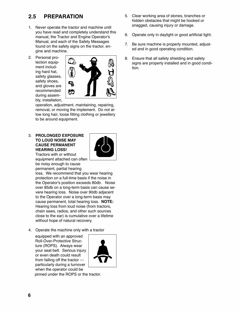
2.� PREPARATION
1. Never operate the tractor and machine until you have read and completely understand this manual, the Tractor and Engine Operator's Manual, and each of the Safety Messages found on the safety signs on the tractor, en-gine and machine.
2. Personal pro-tection equip-ment includ-ing hard hat, safety glasses, safety shoes, and gloves are recommended during assem-bly, installation, operation, adjustment, maintaining, repairing, removal, or moving the implement. Do not al-low long hair, loose fitting clothing or jewellery to be around equipment.
3. PROLONGED EXPOSURE TO LOUD NOISE MAY CAUSE PERMANENT HEARING LOSS!
Tractors with or without equipment attached can often be noisy enough to cause permanent, partial hearing loss. We recommend that you wear hearing protection on a full-time basis if the noise in the Operator's position exceeds 80db. Noise over 85db on a long-term basis can cause se-vere hearing loss. Noise over 90db adjacent to the Operator over a long-term basis may cause permanent, total hearing loss. NOTE: Hearing loss from loud noise (from tractors, chain saws, radios, and other such sources close to the ear) is cumulative over a lifetime without hope of natural recovery.
4. Operate the machine only with a tractor equipped with an approved Roll-Over-Protective Struc-ture (ROPS). Always wear your seat belt. Serious injury or even death could result from falling off the tractor ---particularly during a turnover when the operator could be pinned under the ROPS or the tractor.
5. Clear working area of stones, branches or hidden obstacles that might be hooked or snagged, causing injury or damage.
6. Operate only in daylight or good artificial light.
7. Be sure machine is properly mounted, adjust-ed and in good operating condition.
8. Ensure that all safety shielding and safety signs are properly installed and in good condi-tion.

7
2.6 OPERATING SAFETY
1. Please remember it is important that you read and heed the safety signs on the Woodsplitter. Clean or replace all safety signs if they can-not be clearly read and understood. They are there for your safety, as well as the safety of others. The safe use of this machine is strictly up to you, the operator.
2. All things with moving parts are potentially hazardous. There is no substitute for a cau-tious, safe-minded operator who recognizes potential hazards and follows reasonable safety practices. The manufacturer has designed this Woodsplitter to be used with all its safety equipment properly attached, to minimize the chance of accidents. Study this manual to make sure you have all safety equipment attached.
3. If a safety shield or guard is removed for any reason, it must be replaced before the ma-chine is again operated.
4. Personal protection equipment including hard hat, safety glasses, hearing protection, safety shoes, and tight gloves are recommended during assembly, installation, operation, ad-justment, maintaining, repairing, removal, or moving. Do not allow long hair, loose fitting clothing, or jewellery to be around moving parts.
5. Always use two people to handle heavy, un-wieldy components during assembly, installa-tion, removal or moving.
6. Never place any part of your body, fingers, hands, feet, etc. where it would be in danger if movement should occur during assembly, installation, operation, maintaining, repairing, removal or moving. Keep others away.
7. Do not allow bystanders within 20 feet of machine during operation. Wood chips can fly out and injure others.
8. Do not step over or straddle splitter during operation.
9. Do not try to split more than one log at a time. The extra log can fly out and cause injury.
10. Keep your fingers and hands away from cracks in the log that can open while splitting.
11. Always load logs by holding on the sides, not the top and bottom.
12. Do not load the splitter when the wedge is in motion.
13. Do not try to split logs across the grain. Some kinds can burst or splinter and fly out of ma-chine causing injury.
14. For uneven cut logs, always place the wide end down and the most square end against the splitting wedge.
15. Never use alcoholic beverages or drugs which can hinder alertness or coordination while operating this equipment. Consult your doc-tor about operating this machine while taking prescription medications.
16. Do not allow riders on the machine or tractor at any time. There is no safe place for any riders.
17. Before you operate the machine, check over all pins, bolts, connections and hydraulic com-ponents to be sure all are securely in place and tight. Tighten or replace any leaking, damaged or worn parts immediately.
18. Do not allow anyone who is not familiar with the safety rules and operation instructions to use this machine.
19. Never allow children to operate or be around this machine.
20. Do not operate on slopes or hillsides. Sloping terrain can cause logs to roll or slip.
21. Clear the work area of objects which might be picked up and snagged or entangled in the machine. Do not operate on slippery, wet, muddy or icy surfaces. Good footing prevents slipping and tripping.

8
2.7 HYDRAULIC SAFETY1. Make sure that all the components in the hy-
draulic system are kept in good condition and are clean.
2. Replace any worn, cut, abraded, flattened or crimped hoses and metal lines.
3. Stop engine or motor, disconnect spark plug wire or unplug power cord, and wait for all moving parts to stop before servicing, adjust-ing, repairing or cleaning.
4. Do not attempt any makeshift repairs to the hydraulic lines, fittings or hoses by using tapes, clamps or cements. The hydraulic sys-tem operates under extremely high-pressure. Such repairs will fail suddenly and create a hazardous and unsafe condition.
5. Wear proper hand and eye protection when searching for a high- pressure hydraulic leak. Use a piece of wood or cardboard as a backstop instead of hands to iso-late and identify a leak.
6. If injured by a concentrated high-pressure stream of hydraulic fluid, seek medical atten-tion immediately. Serious infection or toxic reaction can develop from hydraulic fluid piercing the skin surface.
7. Before applying pressure to the system, make sure all components are tight and that lines, hoses and couplings are not damaged.
• Think SAFETY! Work SAFELY!
2.8 STORAGE SAFETY
1. Store the unit in an area away from human activity.
2. Do not permit children to play on or around the stored machine.
3. Store the unit in a dry, level area. Support the frame with planks if required.

9
2.9 TRANSPORT SAFETY
1. Comply with state and local laws governing highway safety and movement of machinery on public roads.
2. The use of flashing amber lights is acceptable in most localities. However, some localities pro-hibit their use. Local laws should be checked for all highway lighting and marking requirements.
3. At all times, when driving the tractor and equip-ment on the road or highway under 20 mph (32 kph) use flashing amber warning lights and a slow moving vehicle (SMV) identification em-blem. Do not exceed 20 mph (32 kph). Reduce speed on rough roads and surfaces.
4. Plan your route to avoid heavy traffic.
5. Be sure the trailer is hitched positively to the towing vehicle and a retainer is used through the hitch coupler. Always attach a safety chain between the hitch and the towing vehicle.
6. Always install transport locks, pins or brackets before transporting.
7. Do not drink and drive.
8. Be a safe and courteous driver. Always yield to oncoming traffic in all situations, including nar-row bridges, intersections, etc. Watch for traffic when operating near or crossing roadways.
9. Never allow riders on either tractor or machine.
2.�0 MAINTENANCE SAFETY
1. Good maintenance is your responsibility. Poor maintenance is an invitation to trouble.
2. Follow good shop practices.
- Keep service area clean and dry. - Be sure electrical outlets and tools are properly grounded. - Use adequate light for the job at hand.
3. Make sure there is plenty of ventilation. Never operate the en-gine of the towing vehicle in a closed building. The exhaust fumes may cause asphyxiation.
4. Before working on this machine, shut off the engine, set the brakes, and remove the igni-tion keys.
6. Never work under equipment unless it is blocked securely.
7. Use personal protection devices such as eye, hand and hearing protectors, when performing any service or maintenance work.
8. Where replacement parts are necessary for periodic maintenance and servicing, genuine factory replacement parts must be used to restore your equipment to original specifica-tions. The manufacturer will not be responsi-ble for injuries or damages caused by use of unapproved parts and/or accessories.
9. A fire extinguisher and first aid kit should be kept readily accessi-ble while performing maintenance on this equipment.
10. Periodically tighten all bolts, nuts and screws and check that all cotter pins are properly installed to ensure unit is in a safe condition.
11. When completing a maintenance or service function, make sure all safety shields and devices are installed before placing unit in service.

�0
2.�� REFUELING SAFETY
1. Handle fuel with care. It is highly flammable.
2. Allow engine to cool for 5 minutes before re-fueling. Clean up spilled fuel before restarting engine.
3. Do not refuel the machine while smoking or when near open flame or sparks.
4. Fill fuel tank outdoors.
5. Prevent fires by keeping machine clean of ac-cumulated trash, grease and debris.
2.�2 TIRE SAFETY1. Failure to follow proper procedures when
mounting a tire on a wheel or rim can pro-duce an explosion which may result in seri-ous injury or death.
2. Do not attempt to mount a tire unless you have the proper equipment and experience to do the job.
3. Have a qualified tire dealer or repair service perform required tire maintenance.
4. When replacing worn tires, make sure they meet the original tire specifications. Never undersize.

��
2.�3 GAS MOTOR SAFETY
BEFORE STARTING ENGINE, READAND UNDERSTAND THE OPERATING AND MAINTENANCE INSTRUCTIONSTHAT CAME WITH YOUR ENGINE.
WARNING: DO NOT
1. DO NOT run engine in an enclosed area. Exhaust gases contain carbon monoxide, an odourless and deadly poison.
2. DO NOT place hands or feet near moving or rotating parts.
3. DO NOT store, spill, or use gasoline near an open flame, or devices such as a stove, furnace, or water heater which use a pilot light or devices which can create a spark.
4. DO NOT refuel indoors where area is not well ventilated. Outdoor refuelling is preferred.
5. DO NOT fill fuel tank while engine is running. Allow engine to cool for 5 minutes before refuel-ling. Store fuel in approved safety containers.
6. DO NOT remove fuel tank cap while engine is running.
7. DO NOT operate engine if gasoline is spilled. Move machine away from the spill and avoid creating any ignition until gasoline has evapo-rated.
8. DO NOT smoke while filling fuel tank.
9. DO NOT choke carburetor to stop engine. Whenever possible, gradually reduce engine speed before stopping.
10. DO NOT run engine above rated speeds. This may result in injury.
11. DO NOT tamper with governor springs, gover-nor links or other parts which may increase the governed speed.
12. DO NOT tamper with the engine speed selected by the original equipment manufacturer.
13. DO NOT check for spark with spark plug or spark plug wire removed.
14 DO NOT crank engine with spark plug removed. If engine is flooded, place throttle in "FAST" position and crank until engine starts.
15. DO NOT strike flywheel with a hard object or metal tool as this may cause flywheel to shat-ter in operation. Use proper tools to service engine.
16 DO NOT operate engine without a muffler. Inspect periodically and replace, if necessary. If engine is equipped with a muffler deflector, inspect periodically and replace, if necessary with correct deflector.
17. DO NOT operate engine with an accumulation of grass, leaves, dirt or other combustible mate-rials in the muffler area.
18. DO NOT use this engine on any forest covered, brush covered, or grass covered unimproved land unless a spark arrester is installed on the muffler. The arrester must be maintained in effective working order by the operator. In the state of California the above is required by law (Section 4442 of the California Public Resourc-es Code). Other states may have similar laws. Federal laws apply on federal land.
19. DO NOT touch hot muffler, cylinder or fins be-cause contact may cause burns.
20. DO NOT run engine with air cleaner or air cleaner cover removed.
WARNING: DO
1. ALWAYS DO remove the wire from the spark plug when servicing the engine or equipment TO PREVENT ACCIDENTAL STARTING. Dis-connect the negative wire from the battery ter-minal if equipped wit a 12 volt starting system.
2. DO keep cylinder fins and governor parts free of grass and other debris which can affect engine speed.
3. DO examine muffler periodically to be sure it is functioning effectively. A worn or leaking muffler should be repaired or replaced as necessary.
4. DO use fresh gasoline. Stale fuel can gum carburetor and cause leakage.
5. DO check fuel lines and fittings frequently for cracks or leaks. Replace if necessary.

�2
EMPLOYEES SIGNATURE EMPLOYERS SIGNATURESIGN-OFF FORM
2.�� SIGN-OFF FORMSurge-Master follows the general Safety Standards specified by the American Society of Agricultural Engi-neers (ASAE) and the Occupational Safety and Health Administration (OSHA). Anyone who will be operating and/or maintaining the Woodsplitter must read and clearly understand ALL Safety, Operating and Mainte-nance information presented in this manual.
Do not operate or allow anyone else to operate this equipment until such information has been reviewed. Annually review this information before the season start-up.
Make these periodic reviews of SAFETY and OPERATION a standard practice for all of your equipment. We feel that an untrained operator is unqualified to operate this machine.
A sign-off sheet is provided for your record keeping to show that all personnel who will be working with the equipment have read and understand the information in the Operator’s Manual and have been instructed in the operation of the equipment.
DATE

�3
REMEMBER - If safety signs have been damaged, removed, become illegible or parts replaced without signs, new signs must be applied. New signs are available from your authorized dealer.
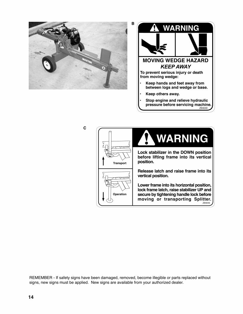
3 SAFETY SIGN LOCATIONSThe types of safety signs and locations on the equipment are shown in the illustration below. Good safety requires that you familiarize yourself with the various safety signs, the type of warning and the area, or particular function related to that area, that requires your SAFETY AWARENESS.
A
Z94039
B
B
A
A
��
C
�������
���������
���������
������������������������������������������� �������� ������ ����� ���� �����������������
��������������������������������������������������������
�������������������������������������������������������������������������������������������������������������������������������� ��� ������������� ���������
������
B
Z94040
REMEMBER - If safety signs have been damaged, removed, become illegible or parts replaced without signs, new signs must be applied. New signs are available from your authorized dealer.
B
A

��
OPERATING SAFETY• Read and understand the Operator’s Man-
ual and all safety signs before operating, servicing, adjusting, repairing or unplugging.
• Do not allow riders.
• Install and secure all guards and shields before starting or operating.
• Keep hands, feet, hair and clothing away from moving parts.
• Place all controls in neutral, stop tractor engine, set park brake, remove ignition key and wait for all moving parts to stop before servicing, adjusting, repairing or unplugging.
• Place all tractor and machine controls in neutral before starting.
• Always wear the appropriate personal safety equipment when operating splitter including but not limited to hard hat, safety shoes, face shield and heavy gloves.
• Clear the area of bystanders, especially small children, before starting.
• Do not operate on slopes or side hills.
• Keep working area clean, neat and dry to prevent slipping and tripping.
• Keep all mechanical and hydraulic compo-nents in good condition. Do not operate with leaks or damaged components.
• Load splitter by holding logs on the side rather than the top and bottom.
• Do not split wood across the grain.
• Review safety instructions with all operators annually.
�.� TO THE NEW OPERATOR OR OWNER
The Surge-Master Trailer Woodsplitter is designed to split any kind of wood or log. Be familiar with the machine before starting.
In addition to the design and configuration of equipment, hazard control and accident pre-vention are dependent upon the awareness, concern, prudence and proper training of per-sonnel involved in the operation, transport, maintenance and storage of equipment. It is the responsibility of the owner or operator to read this manual and to train all other operators before they start working with the machine.
It is the responsibility of the owner or operator to read this manual and to train all other opera-tors before they start working with the machine. Follow all safety instructions exactly. Safety is everyone's business. By following recommend-ed procedures, a safe working environment is provided for the operator, bystanders and the area around the work site. Untrained operators are not qualified to operate the machine.
Many features incorporated into this machine are the result of suggestions made by customers like you. Read this manual carefully to learn how to oper-ate the machine safely and how to set it to provide maximum field efficiency. By following the operating instructions in conjunction with a good maintenance program, your Woodsplitter will provide many years of trouble-free service.
� OPERATION

�6
�.2 MACHINE COMPONENTS
The Surge-Master Trailer Woodsplitter consists of a wedge on the end of a hydraulic cylinder for splitting wood or logs. A gas engine mounted on the front of the frame provides power to a hydraulic pump. The axle frame is used as an oil reservoir. Pressurized
Fig. � MACHINE COMPONENTS
A EngineB Splitter FrameC Control ValveD Control LeverE Hydraulic CylinderF WedgeG Frame LatchH Vertical ConfigurationJ Horizontal ConfigurationK LogL CradleM Oil ReservoirN Front Frame StandO Back Leg Stand
oil from the pump is routed through a double acting valve to control the cylinder position. The 26HVGC, 26HV and the 27HV Splitters can be used in vertical or horizontal configurations.

�7
�.3 MACHINE BREAK-IN
Although there are no operational restrictions on the Trailer Woodsplitter when used for the first time, it is recommended that the following me-chanical items be checked:
A. After Operating For � and � Hours:
1. Check all nuts, bolts and other fasteners. Tighten to their specified torque level.
2. Check hydraulic system for leaks. Tighten all leaking fittings and replace any leaking components.
3. Check machine fluid levels: Fuel, engine oil, and hydraulic oil reservoir. Top up as required.
4. Check for entangled material. Remove all entangled material before resuming work.
5. Check tire pressure. Inflate as required.
B. After Operating For �0 Hours:
1. Repeat steps 1 through 5 listed above.
2. Change engine oil.
3. Go to the normal servicing and mainte-nance schedule as defined in the Mainte-nance Section.
�.� PRE-OPERATION CHECKLIST
Efficient and safe operation of the Surge-Master Trailer Woodsplitter requires that each operator reads and understands the operating procedures and all related safety precautions outlined in this section. A pre-operation checklist is provided for the operator. It is important for both the personal safety and maintaining the good mechanical condition of the Woodsplitter that this checklist is followed.
Before operating the machine and each time thereafter, the following areas should be checked off:
1. Lubricate the machine per the schedule out-lined in the Maintenance Section.
2. Check that the machine is properly attached to the tractor or towing vehicle. Be sure retainers are used through the drawbar pin or ball hitch mechanism.
3. Check the wedge and block. Be sure they are not damaged or broken and is not badly worn. Repair or replace as required.
4. Check for entangled material. Remove this material.
5. Check for hydraulic leaks. Tighten fittings or replace components to stop leaks.
6. Check engine and machine fluid levels. Top up as required.

�8
�.� ASSEMBLY
The machine is shipped from the factory in a partially disassembled configuration and attached to a pallet that provides easy moving and handling. Always use tools, equipment and fork lifts of appropriate size and capacity for the job.
When the machine is shipped, follow this proce-dure when preparing for the customer:
1. Clear the area of bystanders, especially small children.
2. Remove the pallet tie-downs.
3. Use a forklift to lift the pallet/machine from the truck. Carry the load close to the ground as it is moved to the assembly area and positioned.
4. Remove the machine from the pallet.
5. Install the control lever(s):
a. Remove the package of control compo-nents from the frame and lay out.
b. Attach the lever to the control plunger and install the anchor pin and retainer.
c. Raise the lever into its vertical position and install the last anchor pin and retainer.
d. Repeat with the second lever if so equipped.
IMPORTANTBe sure to spread the ends of the cotter pins retainers.
Fig. 2 LAYOUT (typical)
Fig. 3 CONTROL LEVER(S) INSTALLED (typical)
Single Lever
Double Lever
�9
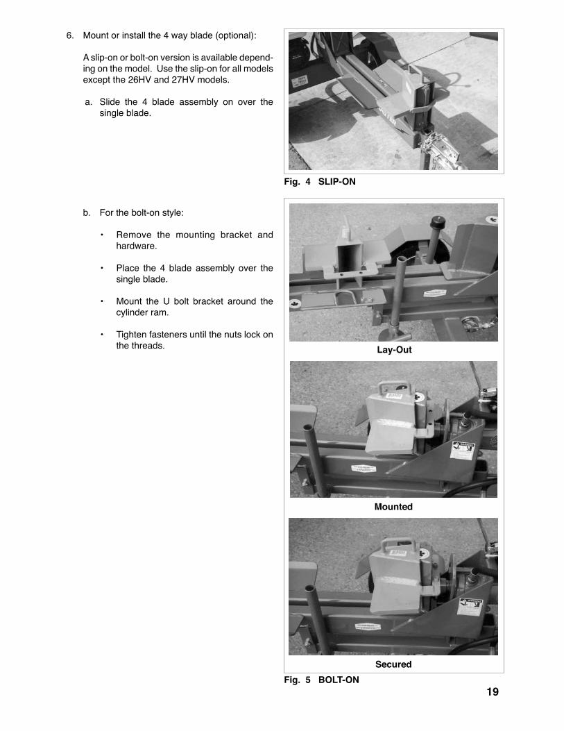
6. Mount or install the 4 way blade (optional):
A slip-on or bolt-on version is available depend-ing on the model. Use the slip-on for all models except the 26HV and 27HV models.
a. Slide the 4 blade assembly on over the single blade.
b. For the bolt-on style:
• Remove the mounting bracket and hardware.
• Place the 4 blade assembly over the single blade.
• Mount the U bolt bracket around the cylinder ram.
• Tighten fasteners until the nuts lock on the threads.
Fig. � SLIP-ON
Lay-Out
Mounted
SecuredFig. � BOLT-ON

20
Fig. 6 ALIGNED
�.6 ATTACHING/UNHOOKING
The Trailer Woodsplitter should always be located on a level, dry area that is free of debris and other foreign objects. When attaching the machine to a tow unit, follow this procedure:
1. Make sure that all bystanders, especially small children, are clear of the working area.
2. Make sure there is enough room and clear-ance to safely back up to the machine.
3. Slowly back the tow vehicle until the coupler on the hitch (if so equipped with a ball hitch) and ball are aligned.
4. For the ball hitch design:
a. Lift the hitch and place the coupler over the ball on the hitch.
b. Flip the latch to lock the coupler around the ball.
c. Install the retainer to secure the linkage.
d. Pull out the anchor pin and pull up to place stand in its stowed position. Install anchor pin.
5. Attach the safety chain securely to the tow frame to prevent unexpected separation. Cross the chains when attaching to a truck. Fig. 7 COUPLER
Fig. 8 RETAINER/STAND/SAFETY CHAIN

2�
Fig. 9 CLEVIS HITCH
6. For the drawbar clevis type of hitch:
a. Install the drawbar pin through the hitch.
b. Install the retainer through the drawbar pin.
c. Attach the safety chain between the hitch and drawbar cage.
7. Connect the wiring harness for the lights (if equipped with optional lights.).
8. Route the harness and cables across the hitch to prevent snagging. Be sure to provide slack for turning.
9. Reverse the above procedure when unhook-ing.
Fig. �0 WIRING HARNESS

22
�.7 CONTROLS
Before starting to work, all operators should famil-iarize themselves with the location and function of the controls.
�. Gas Engine: A Honda engine is used with the unit. Always
read the engine Operator's manual supplied with the machine for the detailed operating procedures.
a. Ignition Switch: This rotary switch controls the electrical
power to the engine electrical system. Turn the switch clockwise to turn the electrical system ON and the engine will run. Turn counter-clockwise to stop the engine.
b. Fuel Shut-Off Valves: Each engine is equipped with a valve
between the fuel tank and the carburator. Slide the fuel valve toward the block to turn ON and away to turn OFF. Turn the fuel OFF when not in use or when transport-ing.
c. Throttle: This lever controls the engine RPM. Move
the lever laterally to increase or decrease the RPM. Always run at maximum throttle while operating.
d. Choke: The choke controls the fuel/air mixture to
the engine. Close the choke when starting if the engine is cold. Open the choke as the engine warms. Always open the choke fully during operation.
e. Starting rope: This retracting rope and T-bar is used to
turn the engine over for starting. Grasp the T-bar firmly and pull the rope sharply to start the engine.
Fig. �� ENGINE CONTROLS
�.0 HP
�.� HP
9.0 HP
23
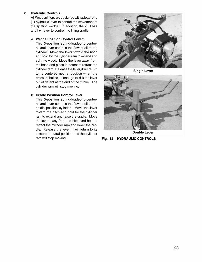
2. Hydraulic Controls: All Woodsplitters are designed with at least one
(1) hydraulic lever to control the movement of the splitting wedge. In addition, the 28H has another lever to control the lifting cradle.
a. Wedge Position Control Lever: This 3-position spring-loaded-to-center-
neutral lever controls the flow of oil to the cylinder. Move the lever toward the base and hold for the cylinder ram to extend and split the wood. Move the lever away from the base and place in detent to retract the cylinder ram. Release the lever, it will return to its centered neutral position when the pressure builds up enough to kick the lever out of detent at the end of the stroke. The cylinder ram will stop moving.
b. Cradle Position Control Lever: This 3-position spring-loaded-to-center-
neutral lever controls the flow of oil to the cradle position cylinder. Move the lever toward the hitch and hold for the cylinder ram to extend and raise the cradle. Move the lever away from the hitch and hold to retract the cylinder ram and lower the cra-dle. Release the lever, it will return to its centered neutral position and the cylinder ram will stop moving. Fig. �2 HYDRAULIC CONTROLS
Single Lever
Double Lever

2�
�.8 FIELD OPERATION
A Surge-Master Trailer Woodsplitter is a self-con-tained machine designed to move a wedge through wood to split it. The model 27HV and 26HVGC splitters can be used in the vertical or horizontal configuration. However the operator has the re-sponsibility of being familiar with all operating and safety procedures and following them.
Each operator should review this section of the manual at the start of the season and as often as required to be familiar with the machine. When us-ing, follow this procedure:
1. Clear the area of bystanders, especially small children.
2. Review and follow the Pre-Operation Checklist (Section 4.4).
3. The Woodsplitter can be used as a stand alone machine or attached to a tow unit.
OPERATING SAFETY• Read and understand the Operator’s Manual
and all safety signs before operating, servic-ing, adjusting, repairing or unplugging.
• Do not allow riders.
• Install and secure all guards and shields before starting or operating.
• Keep hands, feet, hair and clothing away from moving parts.
• Place all controls in neutral, stop tractor engine, set park brake, remove ignition key and wait for all moving parts to stop before servicing, adjusting, repairing or unplugging.
• Place all tractor and machine controls in neutral before starting.
• Always wear the appropriate personal safety equipment when operating splitter including but not limited to hard hat, safety shoes, face shield and heavy gloves.
• Clear the area of bystanders, especially small children, before starting.
• Do not operate on slopes or side hills.
• Keep working area clean, neat and dry to prevent slipping and tripping.
• Keep all mechanical and hydraulic compo-nents in good condition. Do not operate with leaks or damaged components.
• Load splitter by holding logs on the side rather than the top and bottom.
• Do not split wood across the grain.
• Review safety instructions with all operators annually.
Fig. �3 HYDRAULIC CONTROLS
Stand Alone
Attached

2�
4. Starting:
a. Move the machine into its working position next to the wood to be split.
b. Set park brake if connected to tow unit.
c. Lower the front and rear stands if so equipped.
d. Close choke if engine is cold.
e. Move the throttle to its 1/4 to 1/2 throttle position.
f. Open the fuel supply valve.
g. Pull sharply on the starting rope to start the engine.
h. Run the engine for a few minutes to allow it to warm.
i. Gradually open the choke.
j. Slowly increase engine speed to maximum RPM.
k. Place wood or log on the splitting frame.
l. Move the control lever to slide the wedge into the wood or log.
Fig. �� STARTING
Horizontal
Vertical

26
Fig. �� SPLITTING
m. Release the lever when the log splits into 2 pieces or the wedge reaches the base and the wedge will stop.
n. Move the lever in the fully up retracting direction and it will retract fully.
5. Stopping:
a. Release the control lever to stop the wedge.
b. Slow engine RPM to low idle.
c. Stop engine.
6. Emergency Stopping:
Release control lever and stop en-gine if an emergency occurs. Cor-rect emergency situation before starting engine and resuming work.
Horizontal
Vertical
Fig. �6 STOPPING

27
Cradle Stowed
Cradle Lowered
Cradle Loaded
Cradle Raised
Fig. �7 LIFTING CRADLE
7. Lifting Cradle: The 28H is designed with a lifting cradle to as-
sist the operator in raising large, heavy wood or logs to the splitting bed on the machine. Follow this procedure when operating these models:
a. Position Splitter at work site.
b. Start engine.
c. Lower cradle to the ground.
d. Move log on the cradle.
e. Use the control lever to raise the cradle until the bed is level.

28
f. Slide log over until it is centered on the splitting frame.
g. Move the wedge through the log.
h. Retract the wedge.
i. Remove the split pieces of wood from the machine.
j. Repeat with the next log.
Centered
Splitting
Split
Fig. �8 SPLITTING

29
8. Log Placement:
a. Always grasp the log by the sides when placing in the splitter. This will minimize the chance of the operator getting their fingers or arm between the wedge and the log.
b. Always wear the ap-propriate safety gear when working around the machine. This includes but is not limited to:
• Hard hat for protection to the head.
• Face mask for protec-tion to the face and eyes from flying chips.
• Heavy gloves for protection from slivers, chips and pinching.
• Safety shoes with slip resistant soles for pro-tection to the feet and toes from dropped logs and pieces of wood. Slip resistant soles reduce the change of slipping.
Fig. �9 LOG PLACEMENT
Horizontal
Vertical

30
9. Wedge Configuration: All Woodsplitters come from the factory
equipped with a single blade wedge. An optional 4 segment wedge is available for some models that fits over the single blade. An optional 4-way wedge with a U-bolt re-tainer is also available on most models. It can be used at any time with smaller logs or pieces of wood.
Single
�-Way Slip-On
�-Way with U-Bolt Retainer
Fig. 20 WEDGES

3�
Frame Latch
Back Leg Stand
Vertical
Fig. 2� HORIZONTAL TO VERTICAL
10. Horizontal to Vertical: The 26HV and 27HV Series is designed
with a pivoting latching main frame that al-lows it to be used in the horizontal or vertical configuration.
Always lower the back leg stand to support the back of the frame when the splitter is used..

32
11. Operating Hints:
a. Hold the hydraulic lever in the wedge extend direction until the wedge reaches the base or the log/wood splits. Move it in the opposite direction to retract the wedge.
b. Always keep the working area neat and clean to pre-vent tripping. Pile the split and unsplit wood in piles close to the working area. Do not allow pieces to pile up and clutter the area. A cluttered working area can lead to trip-ping and an accident. Do not take chances with safety.
c. Do not place the splitter on muddy, icy, wet or cluttered surfaces. Each can lead to slipping or tripping and cause accidents.
d. When machine is new lu-bricate the plate under the wedge slider each time the machine is used to improve wear and reduce friction and/or binding. Once paint is worn off it will polish itself.
e. Lower the back leg stand be-fore converting the frame into the vertical configuration.
Fig. 22 WORK PLACE
Horizontal
Vertical
Fig. 23 BACK LEG STAND

33
�.9 TRANSPORTING
TRANSPORT SAFETY
When transporting the machine, review and follow these instructions:
1. Be sure all bystanders are clear of the ma-chine.
2. Be sure that the machine is securely attached to the tractor or truck and retainer pins are installed through the drawbar pin or ball hitch mechanism.
3. Secure the frame lock pin on the pivoting frame models. (fig 24)
4. Raise and secure the stabilizers before moving or transporting..
5. Clean the SMV emblem, lights and reflectors and be sure they are working.
6. Be sure you are in compliance with all appli-cable lighting and marking regulations when transporting. Check with your local authorities.
7. Be sure your machine can clearly be seen by overtaking and oncoming traffic.
8. Keep to the right and yield the right-of-way to allow faster traffic to pass. Drive on the road shoulder if permitted by law.
9. Do not allow riders.
10. Always use hazard flashers on the tractor when transporting unless prohibited by law.
• Comply with state and local laws governing highway safety and movement of machinery on public roads.
• The use of flashing amber lights is acceptable in most localities. However, some localities prohibit their use. Local laws should be checked for all highway lighting and marking requirements.
• At all times, when driving the tractor and equipment on the road or highway under 20 mph (32 kph) use flashing amber warn-ing lights and a slow moving vehicle (SMV) identification emblem. Do not exceed 20 mph (32 kph). Reduce speed on rough roads and surfaces.
• Plan your route to avoid heavy traffic.• Always install transport locks, pins or brackets
before transporting.• Do not drink and drive.• Be a safe and courteous driver. Always yield to
oncoming traffic in all situations, including nar-row bridges, intersections, etc. Watch for traffic when operating near or crossing roadways.
• Never allow riders on either tractor or ma-chine.
Fig. 2� LIGHTS
Fig. 2� TRANSPORTING
a. Lock Pin b. Stabilizer

3�
�.�0 STORAGE
• Store the unit in an area away from human activity.
• Do not permit children to play on or around the stored machine.
• Store the unit in a dry, level area. Support the frame with planks if required.
STORAGE SAFETY
After the season's use, the machine should be thoroughly inspected and prepared for storage. Repair or replace any worn or damaged components to prevent any unnecessary down time at the start of next season. To insure a long, trouble free life, this procedure should be followed when preparing the unit for storage:
1. Clear the area of bystanders, espe-cially small children.
2. Fully retract the cylinder ram.
3. Thoroughly wash the machine using a pressure washer to remove all dirt, mud, debris and residue.
4. Inspect the wedge, cylinder ram and wear plates for damage or entangled material. Repair or replace damaged parts. Remove all entangled mate-rial.
5. Touch up all paint nicks and scratch-es to prevent rusting.
6. Turn fuel valve OFF.
7. Select an area that is dry, level and free of debris.
8. Unhook from tractor or tow unit.
9. If the machine cannot be placed inside, cover with a waterproof tar-paulin and tie securely in place.
10. Store the machine in an area away from human activity.
11. Do not allow children to play on or around the stored machine.
Fig. 26 STORED
98D
26HV
28H

3�
� SERVICE AND MAINTENANCE
• Follow ALL the operating, maintenance and safety information in the manual.
• Support the machine with blocks or safety stands when working beneath it.
• Follow good shop practices.
- Keep service area clean and dry. - Be sure electrical outlets and tools are properly grounded. - Use adequate light for the job at hand.
• Make sure there is plenty of ventilation. Never operate the engine of the towing vehicle in a closed building. The exhaust fumes may cause asphyxiation.
• Use only tools, jacks and hoists of sufficient capacity for the job.
• Make sure all guards are in place and properly secured when maintenance work is completed.
• Keep hands, feet, hair and clothing away from moving or rotating parts.
• Clear the area of bystanders, especially small children, when carrying out any main-tenance and repairs or making any adjust-ments.
MAINTENANCE SAFETY �.� SERVICE�.�.� FLUIDS AND LUBRICANTS1. Grease: Use an SAE multi-purpose high temperature
grease with extreme pressure (EP) perform-ance. Also acceptable is an SAE multipurpose lithium base grease.
2. Engine Oil: Use SAE 10W30 or 10W40 multi-viscosity oil
meeting the American Petroleum Institute (API) classification of SF, SG, SH or SJ for normal operating temperatures. Consult the engine manual for unusual operating conditions. Do not mix oil types or viscosities. Check with engine operator's manual.
Crankcase capacity: 5.0 HP 1.0 l (1.1 US qt) 5.5 HP 1.6 l (1.7 US qt) 9.0 HP 2.0 l (2.1 US qt)
3. Engine Gasoline: Use a standard automotive super unleaded
gasoline for all operating conditions.
Fuel tank capacity: 5.0 HP 6.0 l (1.5 US gal) 5.5 HP 7.5 l (2.0 US gal) 9.0 HP 11.2 l (2.5 US gal)
4. Storing Lubricants: Your machine can operate at top efficiency only
if clean lubricants are used. Use clean contain-ers to handle all lubricants. Store them in an area protected from dust, moisture and other contaminants.
�.�.2 GREASINGUse the Maintenance Checklist provided to keep a record of all scheduled maintenance.
1. Use a hand-held grease gun for all greasing.
2. Wipe grease fitting with a clean cloth before greasing to avoid injecting dirt and grit.
3. Replace and repair broken fittings immediately.
4. If fittings will not take grease, remove and clean thoroughly. Also clean lubricant passage. Re-place fitting if necessary.
NOTEHydraulic system uses Dexron III automatic transmission fluid.
36
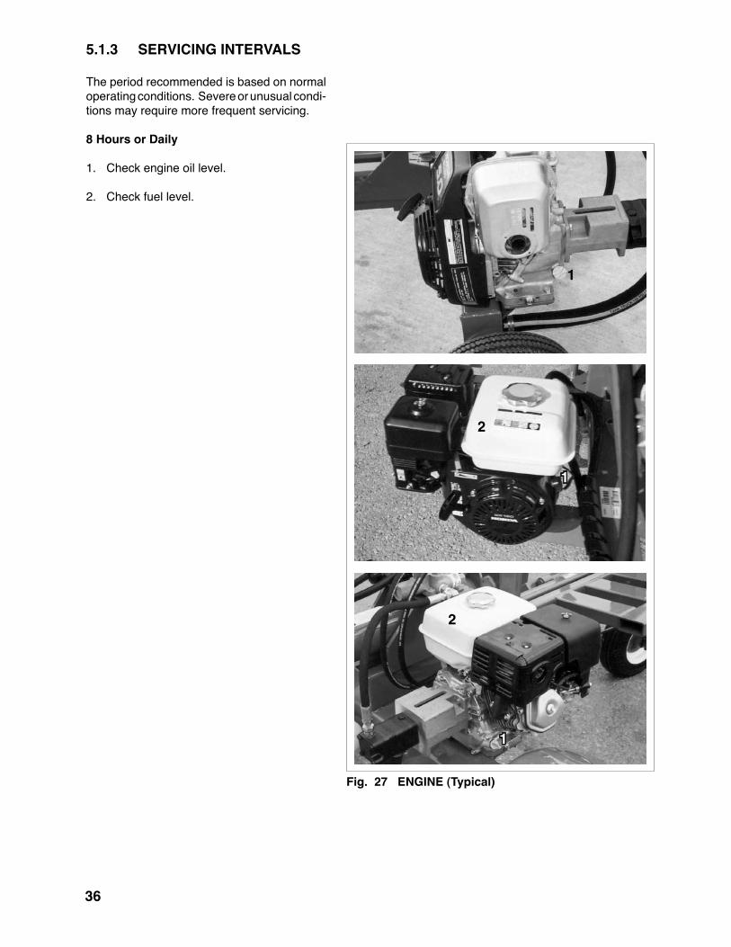
�.�.3 SERVICING INTERVALS
The period recommended is based on normal operating conditions. Severe or unusual condi-tions may require more frequent servicing.
8 Hours or Daily
1. Check engine oil level.
2. Check fuel level.
Fig. 27 ENGINE (Typical)
2
2
�
�
�

37Fig. 29 AIR CLEANER (Typical)
�.0 HP
�.� HP
9.0 HP
Fig. 28 HYDRAULIC OIL LEVEL (Typical)
�0 Hours or Weekly
1. Check oil level in hydraulic reservoir.
2. Check engine air cleaner.

38
Fig. 30 DRAIN PLUG
�.0 HP
�.� HP
9.0 HP
�00 Hours or Annually
1. Change engine oil.
2. Check tire pressure.
39
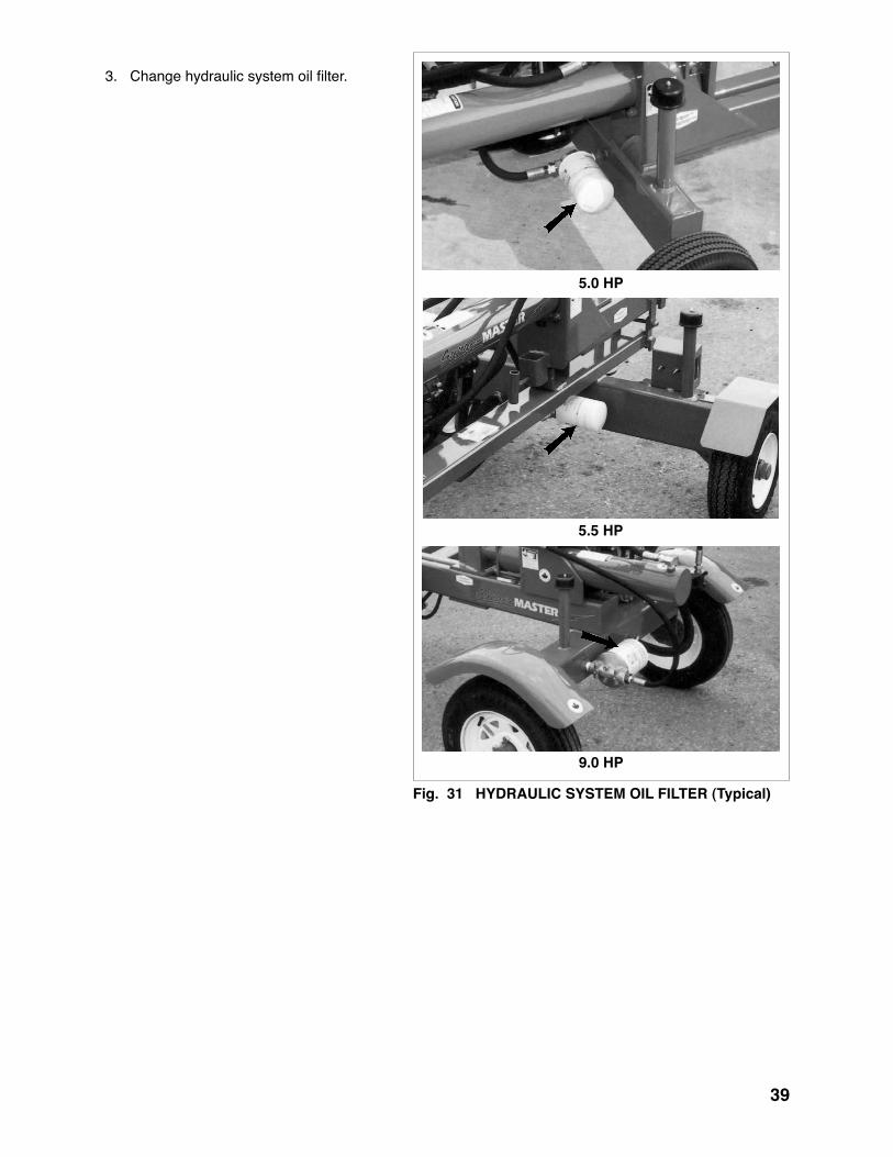
Fig. 3� HYDRAULIC SYSTEM OIL FILTER (Typical)
�.0 HP
�.� HP
9.0 HP
3. Change hydraulic system oil filter.

�0
Fig. 32 AIR CLEANER (Typical)
�.0 HP
�.� HP
9.0 HP
�00 Hours or Annually
4. Replace engine air cleaner.

��
Fig. 33 MACHINE (Typical)
98D
26HV
28H
�00 Hours or Annually
5. Clean machine.

�2
�.�.� SERVICE RECORD
See Lubrication and Maintenance sections for details of service. Copy this page to continue record.
ACTION CODE: CK CHECK CL CLEAN R REPLACE G GREASE CH CHANGE HOURS SERVICED BY MAINTENANCE
8 Hours or DailyCK Engine Oil LevelCK Fuel Level
�0 Hours or WeeklyCK Hydraulic Oil LevelCK Air Cleaner
�00 Hours or AnnuallyCH Engine OilCK Tire PressureCH Hydraulic System Oil FilterR Engine Air CleanerCL Machine

�3
�.2 MAINTENANCE
By following a careful service and maintenance program for your machine, you will enjoy many years of trouble-free operation
�.2.� CLEANING AIR CLEANER
1. Review the operator's manual for the en-gine.
2. Place all controls in neutral, stop and dis-able engine before maintaining.
3. Remove cover over air cleaner.
4. Remove the filter from the engine.
5. Use an air hose to blow the dust and debris out of the filter.
6. Install filter.
7. Install and secure the cover.
Fig. 3� AIR CLEANER
�.0 HP
�.� HP
9.0 HP

��
�.2.2 CHANGING ENGINE OIL
1. Review the Operator's Manual for the en-gine.
2. Place all controls in neutral, stop and dis-able engine before maintaining.
3. Allow the engine to cool before changing the oil. Hot oil can cause burns if it con-tacts exposed skin. It is best to change oil while the engine is warm to keep the contaminants in suspension.
4. Place a pan under the drain plug.
5. Remove the drain plug and allow the oil to drain for 10 minutes.
6. Install and tighten the drain plug.
7. Dispose of the used oil in an approved container.
8. Fill the crankcase with the specified oil.
9. Run the engine for 1-2 minutes and check for oil leaks.
10. If leaks are found around the drain plug or filter, tighten slightly. Repeat step 9.
11. Check engine oil level. Top up as re-quired.
Fig. 3� DRAIN PLUG
�.0 HP
�.� HP
9.0 HP

��
�.2.3 HYDRAULIC SYSTEM OIL FILTER
1. Review the Operator's Manual for the splitter.
2. Place all controls in neutral, stop and disable engine before maintaining.
3. Allow the machine to cool before changing the oil. Hot oil can cause burns if it contacts exposed skin. It is best to change oil while the machine is warm to keep the contami-nants in suspension.
4. Place a pan under the filter head.
5. Remove the oil filter.
6. Install and tighten the drain plug.
7. Remove engine oil filter.
8. Apply a light coat of oil to the O ring and in-stall the replacement filter. Snug up by hand and then tighten 1/2 turn.
9. Fill the crankcase with the specified oil.
10. Run the machine for 1-2 minutes while op-erating cylinder and check filter head for oil leaks.
11. If leaks are found around the filter, tighten slightly. Repeat step 8.
12. Check hydraulic reservoir oil level. Top up as required.
13. Dispose of the spilled oil in an approved con-tainer.
Fig. 36 HYDRAULIC SYSTEM FILTER
98D
26HV
28H

�6
6 TROUBLE SHOOTINGThe Surge-Master Trailer Woodsplitter uses hydraulic power to move a wedge on the end of a cylinder to split wood or logs. It is a simple and reliable system that requires minimal maintenance.
In the following section, we have listed many of the problems, causes and solutions to the problems that you may encounter.
If you encounter a problem that is difficult to solve, even after having read through this trouble shooting section, please call your local dealer, distributor or Surge-Master. Before you call, please have this Op-erator's Manual and the serial number from your Woodsplitter ready.
PROBLEM CAUSE SOLUTION
Wedge doesn't move. No pressurized oil. Oil filter plugged. Change filter.
Wood jammed around wedge. Remove wood.
Wedge jumps. Wedge frame jamming. Lubricate wedge frame wear plates.

�7
7 SPECIFICATIONS
7.� MECHANICAL
SPECIFICATIONS ARE SUBJECT TO CHANGE WITHOUT NOTICE
MODEL 98D 26L/26LGC 26HVGC 26HV Mounting Engine Powered Trailer Mounted Engine Model GC160 GX160 GC160 GX160 Horsepower 5 HP 5.5 HP 5 HP 5.5 HP Cylinder Diameter 4 in. 4 in. 4 in. 4 in. Cylinder Stroke 24 in. 24 in. 24 in. 24 in. Splitting Force 18 ton 20 ton 20 ton 20 ton Cycle TIme 14 sec. 14 sec. 14 sec. 14 sec. Standard Valve Type Auto Return Detent Hydraulic Pump Two Stage Hydraulic Pump Flow 11 GPM 11 GPM 11 GPM 11 GPM Bed Height 16 in. 19 in. 24 in. 24 in. Wedge Height 9 in. 9 in. 9 in. 9 in. Tire Size 4.10 x 6 4.80 x 8 4.80 x 8 4.80 x 8 Tire Type Off Road Highway Highway Highway Safety Chains N/A Standard Standard Standard Ball Hitch Size Clevis Hitch 2 in. 2 in. 2 in. Trailer Light Package Optional Optional Optional Optional Splitter Orientation Horizontal Horizontal Horizontal & Vertical Shipping Weight 250 lbs. 320 lbs. 400 lbs. 400 lbs. Dimensions (L X W x H in.) 68 x 38 x 32 72 x 42 x 36 87 x 49 x 42 87 x 49 x 42 Optional 4-Way Wedge N/A W4110 W4120 W4120
MODEL ��E ��E36 ��E�8 28H 27HV Mounting Engine Powered Trailer Mounted Engine Model GX270 GX270 GX270 GX270 GX270 Horsepower 9 HP 9 HP 9 HP 9 HP 9 HP Cylinder Diameter 4.5 in. 4.5 in. 4.5 in. 4.5 in. 5 in. Cylinder Stroke. 24 in. 36 in. 48 in. 24 in. 24 in. Splitting Force 25 ton 25 ton 25 ton 25 ton 31 ton Cycle TIme 14 sec. 14 sec. 14 sec. 14 sec. 14 sec. Standard Valve Type Auto Return Detent Hydraulic Pump Two Stage Hydraulic Pump Flow 16 GPM 16 GPM 16 GPM 16 GPM 16 GPM Bed Height 21 in. 21 in. 21 in. 21 in. 26 in. Wedge Height 10 in. 10 in. 10 in. 10 in. 10 in. Tire Size 5.3 x 12 5.3 x 12 5.3 x 12 5.3 x 12 5.3 x 12 Safety Chains Standard Standard Standard Standard Standard Ball Hitch Size 2 in. 2 in. 2 in. 2 in. 2 in. Trailer Light Package Optional Optional Optional Optional Optional Splitter Orientation Horizontal Horizontal Horizontal Horizontal Horiz. & Vert. Shipping Weight 500 lbs. 585 lbs. 645 lbs. 650 lbs. 550 lbs. Dimensions (L X W x H in.) 73 x 63 x 35 97 x 63 x 35 121 x 63 x 35 81 x 63 x 38 80 x 48 x 40 Optional 4-Way Wedge W4140 W4130 W4130 W4130 W4130
�8
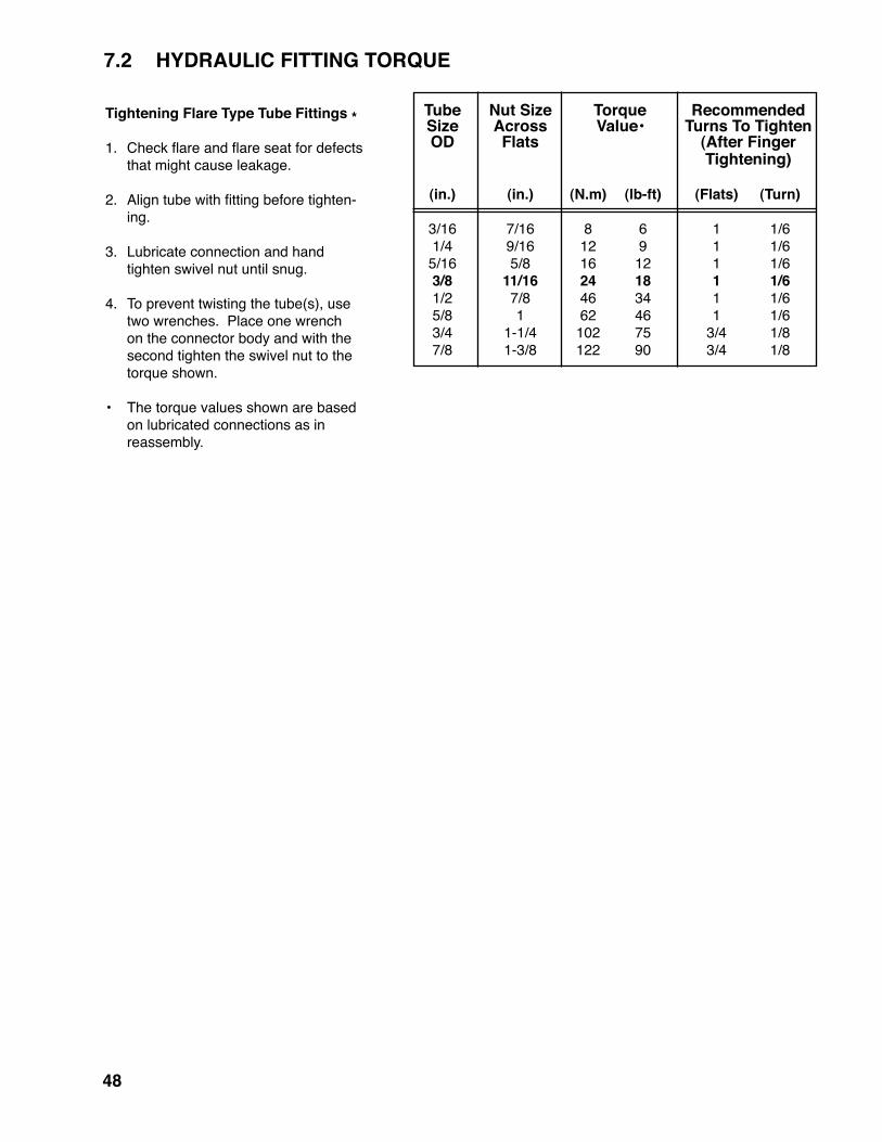
7.2 HYDRAULIC FITTING TORQUE
Tightening Flare Type Tube Fittings *
1. Check flare and flare seat for defects that might cause leakage.
2. Align tube with fitting before tighten-ing.
3. Lubricate connection and hand tighten swivel nut until snug.
4. To prevent twisting the tube(s), use two wrenches. Place one wrench on the connector body and with the second tighten the swivel nut to the torque shown.
• The torque values shown are based on lubricated connections as in
reassembly.
Tube Nut Size Torque Recommended Size Across Value• Turns To Tighten OD Flats (After Finger Tightening)
(in.) (in.) (N.m) (lb-ft) (Flats) (Turn)
3/16 7/16 8 6 1 1/6 1/4 9/16 12 9 1 1/6 5/16 5/8 16 12 1 1/6 3/8 ��/�6 2� �8 � �/6 1/2 7/8 46 34 1 1/6 5/8 1 62 46 1 1/6 3/4 1-1/4 102 75 3/4 1/8 7/8 1-3/8 122 90 3/4 1/8

�9
ENGLISH TORQUE SPECIFICATIONS
METRIC TORQUE SPECIFICATIONS
SAE 2(N.m) (lb-ft)
Bolt Torque*Bolt
Diameter"A"
SAE �(N.m) (lb-ft)
SAE 8(N.m) (lb-ft)
1/4"5/16"3/8"
7/16"1/2"
9/16"5/8"3/4"7/8"1"
81327416195
128225230345
6102030456095
165170225
12254572110155215390570850
919335380115160290420630
173663
100155220305540880
1320
12274575115165220400650970
8.8(N.m) (lb-ft)
Bolt Torque*Bolt
Diameter"A"
�0.9(N.m) (lb-ft)
M3M4M5M6M8
M10M12M14M16M20M24M30M36
.536
10255090
140225435750
14952600
.42.247
183766
10316632155311031917
1.84.59
153570
125200310610
105021003675
1.33.3711265292
148229450774
15502710
Torque figures indicated above are valid for non-greased or non-oiled threads and heads unless oth-erwise specified. Therefore, do not grease or oil bolts or capscrews unless otherwise specified in this manual. When using locking elements, increase torque values by 5%.
* Torque value for bolts and capscrews are identified by their head markings.
7.3 BOLT TORQUECHECKING BOLT TORQUE

�0
8 INDEX
PAGES
Safety ..............................................................2 Equipment Safety Guidelines ....................4 Gas Motor Safety ....................................11 General Safety .........................................3 Hydraulic Safety ........................................8 Maintenance Safety ..................................9 Operating Safety .......................................7 Preparation ...............................................6 Refuelling Safety .....................................10 Safety Training ..........................................5 Safety Signs ..............................................5 Sign-Off Form..........................................12 Storage Safety ..........................................8 Tire Safety ...............................................10 Transport Safety ........................................9Safety Sign Locations ....................................13Service and Maintenance ..............................35 Service ....................................................35 Fluid and Lubricants ................................35 Greasing .................................................35 Service Record .......................................42 Servicing Intervals ...................................36Specifications ................................................33 Bolt Torque ..............................................49 Hydraulic Fitting Torque ..........................48 Mechanical ..............................................47
T
Trouble Shooting ...........................................46
PAGEIntroduction ......................................................1
O
Operation .......................................................15 Assembly ................................................18 Attaching/Unhooking ...............................20 Controls ...................................................22 Field Operation .......................................24 Machine Break-In ....................................17 Machine Components .............................16 Pre-Operation Checklist ..........................17 Storage ...................................................34 To the New Operator or Owner ...............15 Transporting ............................................33
I

SURGE-MASTER
4144 BOOMER LINEST. CLEMENTS, ONN0B 2M0 CANADAPH: (519) 699-9283
FAX: (519) 699-4146
PRINTED IN CANADANUMBER: MARCH 2008 PART NUMBER: Z97025