operator's manual - cdnmedia.endeavorsuite.com · operator's manual bx25dlb la240a bt602...
TRANSCRIPT

1AGAJBJAP0010
OPERATOR'S MANUAL
BX25DLBLA240ABT602
MODELS
KUBOTA Corporation
U.S.A. : KUBOTA TRACTOR CORPORATION3401 Del Amo Blvd., Torrance, CA 90503, U.S.A.Telephone : (310)370-3370
Canada : KUBOTA CANADA LTD.5900 14th Avenue, Markham, Ontario, L3S 4K4, CanadaTelephone : (905)294-7477
France : KUBOTA EUROPE S.A.S19-25, Rue Jules Vercruysse, Z.I. BP88, 95101 Ar enteuil Cedex, FranceTelephone : (33)1-3426-3434
Italy : KUBOTA EUROPE S.A.S Italy BranchVia Grandi, 29 20068 Peschiera Borrome (MI) ItalyTelephone : (39)02-51650377
Germany : KUBOTA (DEUTSCHLAND) GmbHSenefelder Str. 3-5 63110 Rod au /Nieder-Roden, GermanyTelephone : (49)6106-873-0
U.K. : KUBOTA (U.K.) LTD.Dormer Road, Thame, Oxfordshire, OX9 3UN, U.K.Telephone : (44)1844-214500
Spain : KUBOTA ESPAÑA S.A.Avenida Recomba No.5, Poli no Industrial la La una, Le anes, 28914 (Madrid) SpainTelephone : (34)91-508-6442
Australia : KUBOTA TRACTOR AUSTRALIA PTY LTD.25-29 Permas Way, Tru anina, VIC 3029, AustraliaTelephone : (61)-3-9394-4400
Malaysia : SIME KUBOTA SDN. BHD.No.3 Jalan Sepadu 25/123 Taman Perindustrian Axis,Seksyen 25, 40400 Shah Alam, Selan or Darul Ehsan MalaysiaTelephone : (60)3-736-1388
Philippines : KUBOTA PHILIPPINES, INC.232 Quirino Hi hway, Baesa, Quezon City 1106, PhilippinesTelephone : (63)2-422-3500
Taiwan : SHIN TAIWAN AGRICULTURAL MACHINERY CO., LTD.16, Fen pin 2nd Rd, Taliao Shian Kaohsiun 83107, Taiwan R.O.C.Telephone : (886)7-702-2333
Indonesia : PT KUBOTA MACHINERY INDONESIATower A at Ei htyEi ht@Kasablanka Lantai 16Jalan Raya Casablanka Kav. 88, Jakarta 12870 IndonesiaTelephone : (62)-21-29568-720
Thailand : SIAM KUBOTA CORPORATION CO., LTD.101/19-24 Moo 20, Navanakorn Industrial Estate, Tambon Khlon nuen , Amphur Khlon luan ,Pathumthani 12120, THAILANDTelephone : (66)2-909-0300
Korea : KUBOTA KOREA CO., LTD.41-27, Jayumuyeok- il, Baeksan-myeon, Gimje-si, Jeollabuk-do, KoreaTelephone : (82)-63-544-5822
India : KUBOTA AGRICULTURAL MACHINERY INDIA PVT. LTD.No.15, Medavakkam Road, Sholin anallur, Chennai-600119, T.N., IndiaTelephone : (91)44-6104-1500
Vietnam : KUBOTA VIETNAM CO., LTD.Lot B-3A2-CN, My Phuoc 3 Industrial Park, Ben Cat District, Binh Duon Province, VietnamTelephone : (84)-650-3577-507
Western Division : 1175 S. Guild Avc., Lodi, CA 95240Telephone : (209)334-9910
Central Division : 14855 FAA Blvd., Fort Worth, TX 76155Telephone : (817)571-0900
Northern Division : 6300 at One Kubota Way, Groveport, OH 43125Telephone : (614)835-1100
Southeast Division : 1025 Northbrook Parkway, Suwanee, GA 30024Telephone : (770)995-8855
Code No. K2792-7121-4AU. I. 4-4. -. K
© KUBOTA Corporation 2012
READ AND SAVE THIS MANUAL
BX25DLB·LA240A·BT602
PRINTED IN U.S.A.

Abbreviations Definitions
2WD
4WD
API
ASABE
ASTM
DIN
DT
fpm
Hi-Lo
HST
m/s
PTO
RH/LH
ROPS
rpm
r/s
SAE
SMV
Two Wheel Drive
Four Wheel Drive
American Petroleum Institute
American Society of Agricultural and Biological Engineers, USA
American Society of Testing and Materials, USA
Deutsches Institut für Normung, GERMANY
Dual Traction [4WD]
Feet Per Minute
High Speed-Low Speed
Hydrostatic Transmission
Meters Per Second
Power Take Off
Right-hand and left-hand sides are determined by facing inthe direction of forward travel
Roll-Over Protective Structures
Revolutions Per Minute
Revolutions Per Second
Society of Automotive Engineers, USA
Slow Moving Vehicle
ABBREVIATION LIST
California Proposition 65
Engine exhaust, some of its constituents, certain vehicle components and fluids, contain or emit chemicals known to the State of California to cause cancer and birth defects or other reproductive harm.
WARNING
IMPORTANT
The engine in this machine is not equipped by the manufacturer with a standard spark arrester.It is a violation of California Public Resource Code Section 4442 to use or operate this engine on or near any forest-covered, brush-covered land, or grass- covered land unless the exhaust system is equipped with a working spark arrester meeting state laws. Other states or federal areas may have similar laws.

UNIVERSAL SYMBOLSAs a guide to the operation of your tractor, various universal symbols have been utilized on the instruments and controls. The symbols are shown below with an indication of their meaning.
Safety Alert Symbol
Read Operator's Manual
Hourmeter/Elapsed Operating Hours
Diesel Fuel
Fuel-Level
Empty
Full
Engine-Run
Diesel Preheat/Glow Plugs (Low Temperature Start Aid)
Starter Control
Engine-Stop
Engine Oil-Pressure
Engine Coolant-Temperature
Battery Charging Condition
Electrical Power-accessories
Hazard Warning Lights
Turn Signal
Headlight
Work Light
Engine Speed Control
Slow
Fast
Brake
Parking Brake
Four-Wheel Drive-Off
Four-Wheel Drive-On
Speed set-Off
Speed set-On
Differential Lock
Hydraulic Control-Lowered Position
Hydraulic Control-Raised Position
3-Point Lowering Speed Control
Remote Cylinder-Retract
Remote Cylinder-Extend
Mid-PTO
Mid-Rear-PTO
Rear-PTO
Power Take-Off Clutch Control-Off Position
Power Take-Off Clutch Control-On Position

This symbol, the industry's "Safety Alert Symbol", is used throughout this manual and on labels on the machine itself to warn of the possibility of personal injury. Read these instructions carefully. It is essential that you read the instructions and safety regulations before you attempt to assemble or use this unit.
Indicates an imminently hazardous situation which, if not avoided, will result in death or serious injury.
Indicates a potentially hazardous situation which, if not avoided, could result in death or serious injury.
Indicates a potentially hazardous situation which, if not avoided, could result in minor or moderate injury.
Indicates that equipment or property damage could result if instructions are not followed.
Gives helpful information.
You are now the proud owner of a KUBOTA Tractor. This tractor is a product of KUBOTA’s quality engineering and manufacturing. It is made of the excellent materials and under rigid quality control systems. It will give you long, satisfactory service. To obtain the best use of your tractor, please read this manual carefully. It will help you become familiar with the operation of the tractor and contains many helpful hints about tractor maintenance. It is KUBOTA's policy to utilize, as quick as possible, every advance in our research. The immediate use of new techniques in the manufacturing of products may cause some small parts of this manual to become outdated. KUBOTA distributors and dealers will have the most up-to-date information. Please do not hesitate to consult them.
FOREWORD

CONTENTS
SAFE OPERATION ............................................................................................ -1TRACTOR................................................................................................................ 1LOADER .................................................................................................................. 7BACKHOE................................................................................................................ 9SERVICING................................................................................................................. 1
SPECIFICATIONS OF THE TRACTOR ...................................................................... 3SPECIFICATION TABLE ......................................................................................... 3TRAVELING SPEEDS ............................................................................................. 4
SPECIFICATIONS OF THE LOADER......................................................................... 5LOADER SPECIFICATIONS ................................................................................... 5BUCKET SPECIFICATIONS.................................................................................... 5DIMENSIONAL SPECIFICATIONS ......................................................................... 6OPERATIONAL SPECIFICATIONS......................................................................... 7LOADER TERMINOLOGY....................................................................................... 9
SPECIFICATIONS OF THE BACKHOE.................................................................... 10BACKHOE SPECIFICATIONS............................................................................... 10
Dimensions.....................................................................................................................10Specifications..................................................................................................................11Lift Capacity (Per SAE J31) ............................................................................................13
BACKHOE TERMINOLOGY.................................................................................. 14
IMPLEMENT LIMITATIONS ...................................................................................... 15
INSTRUMENT PANEL AND CONTROLS................................................................. 17
PRE-OPERATION CHECK OF THE TRACTOR....................................................... 19DAILY CHECK ....................................................................................................... 19
PRE-OPERATION CHECK OF THE LOADER ......................................................... 20LUBRICATION....................................................................................................... 20TRANSMISSION FLUID ........................................................................................ 20REAR BALLAST .................................................................................................... 20
Liquid Ballast in Rear Tires.............................................................................................20TIRE INFLATION ................................................................................................... 20TEST OPERATION................................................................................................ 20REMOVING AIR FROM HYDRAULIC SYSTEM ................................................... 21
PRE-OPERATION CHECK OF THE BACKHOE....................................................... 22PRE-OPERATION CHECKS ................................................................................. 22OPERATOR'S SEAT ............................................................................................. 22BALLAST ............................................................................................................... 22TIRE INFLATION ................................................................................................... 22
OPERATING THE ENGINE....................................................................................... 23STARTING THE ENGINE...................................................................................... 23
Cold Weather Starting ....................................................................................................25

CONTENTS
Block Heater (Option) .....................................................................................................25STOPPING THE ENGINE...................................................................................... 25WARMING UP ....................................................................................................... 26
Warm-up and Transmission Oil in the Low Temperature Range....................................26JUMP STARTING .................................................................................................. 26
OPERATING THE TRACTOR................................................................................... 27OPERATING NEW TRACTOR .............................................................................. 27
Do not Operate the Tractor at Full Speed for the First 50 Hours....................................27Changing Lubricating Oil for New Tractors.....................................................................27
BOARDING AND LEAVING THE TRACTOR ........................................................ 27OPERATING FOLDABLE ROPS........................................................................... 27
To Fold the ROPS ..........................................................................................................27To Raise the ROPS to Upright Position..........................................................................28Adjustment of Foldable ROPS........................................................................................29
STARTING............................................................................................................. 30Operator's Seat...............................................................................................................30Seat Belt .........................................................................................................................31Head Light Switch...........................................................................................................31Hazard Light Switch........................................................................................................31Turn Signal Light Switch .................................................................................................31Brake Pedal ....................................................................................................................31Range Gear Shift Lever (Hi-Lo) ......................................................................................32Front Wheel Drive Lever.................................................................................................33Hand Throttle Lever ........................................................................................................33Parking Brake Pedal .......................................................................................................33Speed Control Pedal.......................................................................................................34Speed Set Device...........................................................................................................34
STOPPING............................................................................................................. 35Stopping..........................................................................................................................35
CHECK DURING DRIVING ................................................................................... 35Immediately Stop the Engine if: ......................................................................................35Easy Checker(TM)..........................................................................................................36Fuel Gauge.....................................................................................................................36Coolant Temperature Gauge..........................................................................................36Hourmeter/Tachometer...................................................................................................37
PARKING............................................................................................................... 37Parking............................................................................................................................37
ACCESSORY......................................................................................................... 3812V Electric Outlet ..........................................................................................................38Glove Box .......................................................................................................................38
OPERATING TECHNIQUES ................................................................................. 38Differential Lock ..............................................................................................................38Operating the Tractor on a Road....................................................................................39Operating on a Slopes and Rough Terrain .....................................................................39Transport the Tractor Safely ...........................................................................................39Directions for Use of Power Steering..............................................................................39
REVERSING THE SEAT ....................................................................................... 40
PTO ........................................................................................................................... 42PTO OPERATION.................................................................................................. 42
PTO Select Lever ...........................................................................................................42

CONTENTS
PTO Clutch Lever ...........................................................................................................43PTO Shaft Cover and Shaft Cap ....................................................................................43Stationary PTO ...............................................................................................................43PTO Drive Shaft..............................................................................................................44
3-POINT HITCH & DRAWBAR.................................................................................. 453-POINT HITCH..................................................................................................... 46
Attaching and detaching implements..............................................................................46Lifting Rod (Right)...........................................................................................................46Top Link..........................................................................................................................46Check Chains .................................................................................................................46
HITCH .................................................................................................................... 46Removing the 3-Point Hitch ............................................................................................47Installing the 3-Point Hitch ..............................................................................................47
HYDRAULIC UNIT..................................................................................................... 483-POINT HITCH CONTROL SYSTEM................................................................... 48
Hydraulic Control ............................................................................................................483-point Hitch Lowering Speed.........................................................................................48
AUXILIARY HYDRAULICS .................................................................................... 49Hydraulic Outlet ..............................................................................................................49
INSTALLING MOWER........................................................................................... 50MOWER LIFT LINKAGE SYSTEM ........................................................................ 51
Cutting Height Control Dial .............................................................................................51Hydraulic Control Unit Use Reference Chart ..................................................................52
TIRES, WHEELS AND BALLAST.............................................................................. 53TIRES..................................................................................................................... 53
Inflation Pressure............................................................................................................53Dual Tires .......................................................................................................................53
WHEEL TREAD ..................................................................................................... 53Front Wheels ..................................................................................................................53Rear Wheels ...................................................................................................................54
BALLAST ............................................................................................................... 55Front Ballast....................................................................................................................55Rear Ballast ....................................................................................................................55
OPERATING THE LOADER...................................................................................... 57FILLING THE BUCKET.......................................................................................... 57LIFTING THE LOAD .............................................................................................. 57CARRYING THE LOAD ......................................................................................... 58DUMPING THE BUCKET ...................................................................................... 58LOWERING THE BUCKET.................................................................................... 58OPERATING WITH FLOAT CONTROL................................................................. 58LOADING FROM A BANK ..................................................................................... 59PEELING AND SCRAPING ................................................................................... 60LOADING LOW TRUCKS OR SPREADERS FROM A PILE................................. 60BACKFILLING........................................................................................................ 60HANDLING LARGE HEAVY OBJECTS................................................................. 61VALVE LOCK......................................................................................................... 62ATTACHING ATTACHMENTS .............................................................................. 62DETACHING ATTACHMENTS.............................................................................. 64

CONTENTS
DISMOUNTING THE LOADER.............................................................................. 64ATTACHMENTS .................................................................................................... 64
Bucket.............................................................................................................................64Pallet fork........................................................................................................................64
ASSEMBLE PALLET FORK .................................................................................. 64
OPERATING THE BACKHOE................................................................................... 66OPERATING SPEED............................................................................................. 66BACKHOE CONTROLS......................................................................................... 66
Boom & Swing Lever ......................................................................................................66Dipperstick & Bucket Lever.............................................................................................67Stabilizer Control Levers.................................................................................................67
PLACING THE STABILIZERS ............................................................................... 67GENERAL BACKHOE OPERATION ..................................................................... 68
Dipperstick Digging.........................................................................................................68Spoil Pile Location ..........................................................................................................68Straight Wall or Cemetery Digging .................................................................................68Stabilizer pads (Standard) ..............................................................................................69Stabilizer pads (Option) ..................................................................................................69
TRANSPORTING................................................................................................... 70Driving to the Job-site .....................................................................................................70Trailer Transporting ........................................................................................................70
MAINTENANCE OF THE TRACTOR........................................................................ 71SERVICE INTERVALS .......................................................................................... 71LUBRICANTS, FUEL AND COOLANT .................................................................. 72
PERIODIC SERVICE OF THE TRACTOR................................................................ 75HOW TO OPEN THE HOOD ................................................................................. 75
Hood ...............................................................................................................................75Engine Cover ..................................................................................................................75
DAILY CHECK ....................................................................................................... 76Walk Around Inspection..................................................................................................76Checking and Refueling..................................................................................................77Checking Engine Oil Level..............................................................................................77Checking Transmission Fluid Level ................................................................................78Checking Coolant Level..................................................................................................78Cleaning Panel and Radiator Screen .............................................................................79Checking Brake Pedal ....................................................................................................79Checking Gauges, Meters and Easy Checker(TM) ........................................................79Checking Head Light, Hazard Light etc. .........................................................................79Checking Seat Belt and ROPS.......................................................................................79Checking and Cleaning of Electrical Wiring and Battery Cables ....................................80Checking Movable Parts.................................................................................................80
EVERY 50 HOURS................................................................................................ 80Lubricating Grease Fittings.............................................................................................80Checking Engine Start System.......................................................................................81Checking OPC System...................................................................................................81Checking Wheel Bolt Torque..........................................................................................82
EVERY 100 HOURS.............................................................................................. 82Battery ............................................................................................................................82Cleaning Air Cleaner Element ........................................................................................84
CONTENTS
Checking Fuel Filter........................................................................................................84Adjusting Fan belt Tension .............................................................................................85Adjusting HST Neutral Spring (for Speed Control Pedal) ...............................................86Adjusting Brake Pedal ....................................................................................................86
EVERY 200 HOURS.............................................................................................. 87Replacing Engine Oil Filter .............................................................................................87Changing Engine Oil.......................................................................................................87Replacing Transmission Oil Filter ...................................................................................88Adjusting Toe-in..............................................................................................................88
EVERY 400 HOURS.............................................................................................. 89Adjusting Front Axle Pivot...............................................................................................89Changing Transmission Fluid .........................................................................................89Cleaning Transmission Strainer......................................................................................90Changing Front Axle Case Oil ........................................................................................90Replacing Fuel Filter Element.........................................................................................90
EVERY 800 HOURS.............................................................................................. 90Adjusting Engine Valve Clearance .................................................................................90
EVERY 1000 HOURS OR 1 YEAR........................................................................ 90Replacing Air Cleaner Element.......................................................................................90
EVERY 1500 HOURS............................................................................................ 91Checking Fuel Injection Nozzle Injection Pressure.........................................................91
EVERY 2000 HOURS OR 2 YEARS ..................................................................... 91Flushing Cooling System and Changing Coolant ...........................................................91Anti-Freeze .....................................................................................................................91
EVERY 3000 HOURS............................................................................................ 92Checking Injection Pump................................................................................................92
EVERY 1 YEAR ..................................................................................................... 92Checking Radiator Hoses and Clamps...........................................................................92Checking Power Steering Line .......................................................................................93Checking Fuel Lines .......................................................................................................93Checking Intake Air Line.................................................................................................93Checking Engine Breather Hose ....................................................................................94
EVERY 4 YEARS................................................................................................... 94Replacing Radiator Hose (Water pipes) .........................................................................94Replacing Power Steering Hose.....................................................................................94Replacing Fuel Lines ......................................................................................................94Replacing Engine Breather Hose ...................................................................................94Replacing Intake Air Line................................................................................................94
SERVICE AS REQUIRED...................................................................................... 94Bleeding Fuel System.....................................................................................................94Replacing Fuse...............................................................................................................95Replacing Light Bulb.......................................................................................................95
MAINTENANCE OF THE LOADER........................................................................... 96LUBRICATION....................................................................................................... 96RE-TIGHTENING OF HARDWARE....................................................................... 96
Tightening Bolts and Nuts...............................................................................................96DAILY CHECKS..................................................................................................... 97EVERY 50 HOURS................................................................................................ 97
Checking main frame bolt and nut torque.......................................................................97
MAINTENANCE OF THE BACKHOE........................................................................ 98

CONTENTS
DAILY CHECKS..................................................................................................... 98LUBRICATION....................................................................................................... 99BUCKET SERVICE................................................................................................ 99
Changing the Backhoe Bucket .......................................................................................99Changing the Bucket Teeth ............................................................................................99General torque specification .........................................................................................100
STORAGE OF THE TRACTOR............................................................................... 101TRACTOR STORAGE ......................................................................................... 101REMOVING THE TRACTOR FROM STORAGE................................................. 101
REMOVING THE LOADER ..................................................................................... 102STORAGE OF THE LOADER.............................................................................. 103
REINSTALLING THE LOADER............................................................................... 104
REMOVING THE BACKHOE .................................................................................. 106REMOVAL OF THE BACKHOE........................................................................... 106STORAGE OF THE BACKHOE........................................................................... 108
REINSTALLING THE BACKHOE............................................................................ 109
TROUBLESHOOTING............................................................................................. 111ENGINE TROUBLESHOOTING .......................................................................... 111
OPTIONS................................................................................................................. 112
APPENDICES.......................................................................................................... 113INDEX .................................................................................................................. 113

-1SAFE OPERATION
SAFE OPERATION
TRACTORCareful operation is your best insurance against anaccident.Read and understand this manual carefully beforeoperating the tractor.All operators, no matter how much experience they mayhave, should read this and other related manuals beforeoperating the tractor or any implement attached to it. It isthe owner's obligation to instruct all operators in safeoperation.1. Know your equipment and its limitations. Read thisentire manual before attempting to start and operatethe tractor.
2. Pay special attention to the danger, warning andcaution labels on the tractor.
3. Do not operate the tractor or any implement attachedto it while under the influence of alcohol, medication,controlled substances or while fatigued.
4. Carefully check the vicinity before operating tractor orany implement attached to it. Do not allow anybystanders around or near tractor during operation.
5. Before allowing other people to use your tractor,explain how to operate and have them read thismanual before operation.
6. Never wear loose, torn, or bulky clothing aroundtractor. It may catch on moving parts or controls,leading to the risk of an accident. Use additional safetyitems, e.g. hard hat, safety boots or shoes, eye andhearing protection, gloves, etc., as appropriate orrequired.
7. Do not allow passengers to ride on any part of thetractor at anytime. The operator must remain in thetractor seat during operation.
8. Check brakes, linkage pins and other mechanicalparts for improper adjustment and wear. Replace wornor damaged parts promptly. Check the tightness of allnuts and bolts regularly. (For further details, see"PERIODIC SERVICE OF THE TRACTOR" section.)
9. Keep your tractor clean. Dirt, grease, and trash buildup may contribute to fires and lead to personal injury.
10.Use only implements meeting the specifications listedunder "IMPLEMENT LIMITATIONS" in this manual orimplements approved by KUBOTA.
11.Use proper weights on the front or rear of the tractor toreduce the risk of upsets. When using the front loader,put an implement or ballast on the 3-point hitch toimprove stability. Follow the safe operatingprocedures specified in the implement or attachmentmanual.
12.Do not modify the tractor. Unauthorized modificationmay affect the function of the tractor, which may resultin personal injury.
C CAB, ROPS1. KUBOTA recommends the use of a CAB or Roll Over
Protective Structures (ROPS) and seat belt in almostall applications. This combination will reduce the riskof serious injury or death, should the tractor be upset.Check for overhead clearance which may interferewith a CAB or ROPS.
2. Set parking brake and stop engine. Remove anyobstruction that may prevent raising or folding of theROPS. Do not allow any bystanders. Always performfunction from a stable position at the rear of the tractor.Hold the top of the ROPS securely when raising orfolding. Make sure all pins are installed and locked.
3. If the CAB or ROPS is loosened or removed for anyreason, make sure that all parts are reinstalledcorrectly before operating the tractor.
4. Never modify or repair any structural member of aCAB or ROPS because welding, bending, drilling,grinding, or cutting may weaken the structure.
5. A damaged CAB or ROPS structure must be replaced,not repaired or revised.
6. If any structural member of the CAB or ROPS isdamaged, replace the entire structure at your localKUBOTA Dealer.
7. If the tractor is equipped with a foldable ROPS it maybe temporarily folded down only when absolutelynecessary for areas with height constraints.(There is no operator protection provided by the ROPSin the folded position. For operator safety the ROPSshould be placed in the upright and locked positionand the seat belt fastened for all other operations.)
8. Always use the seat belt if the tractor has a CAB orROPS.Do not use the seat belt if a foldable ROPS is down orthere is no ROPS. Check the seat belt regularly andreplace if frayed or damaged.
1. BEFORE OPERATING THE TRACTOR
SAFE OPERATION-2
Operator safety is a priority. Safe operation, specificallywith respect to overturning hazards, entails understandingthe equipment and environmental conditions at the time ofuse. Some prohibited uses which can affect overturninghazards include traveling and turning with implementsand loads carried too high etc. This manual sets forthsome of the obvious risks, but the list is not, and cannotbe, exhaustive. It is the operator's responsibility to be alertfor any equipment or environmental condition that couldcompromise safe operation.
C Starting1. Always sit in the operator's seat when starting engine
or operating levers or controls. Adjust seat perinstructions in the operating the tractor section. Neverstart engine while standing on the ground.
2. Before starting the engine, make sure that all levers(including auxiliary control levers) are in their neutralpositions, that the parking brake is engaged, and thatthe Power Take-Off (PTO) is disengaged or "OFF".Fasten the seat belt if the tractor has a CAB, a fixedROPS or a foldable ROPS in the upright and lockedposition.
3. Do not start engine by shorting across starterterminals or bypassing the safety start switch.Machine may start in gear and move if normal startingcircuitry is bypassed.
4. Do not operate or idle engine in a non-ventilated area.Carbon monoxide gas is colorless, odorless, anddeadly.
5. Check before each use that operator presencecontrols are functioning correctly. Test safety systems.(See "Checking Engine Start System" and "CheckingOPC System" in "EVERY 50 HOURS" in "PERIODICSERVICE OF THE TRACTOR" section.)Do not operate unless they are functioning correctly.
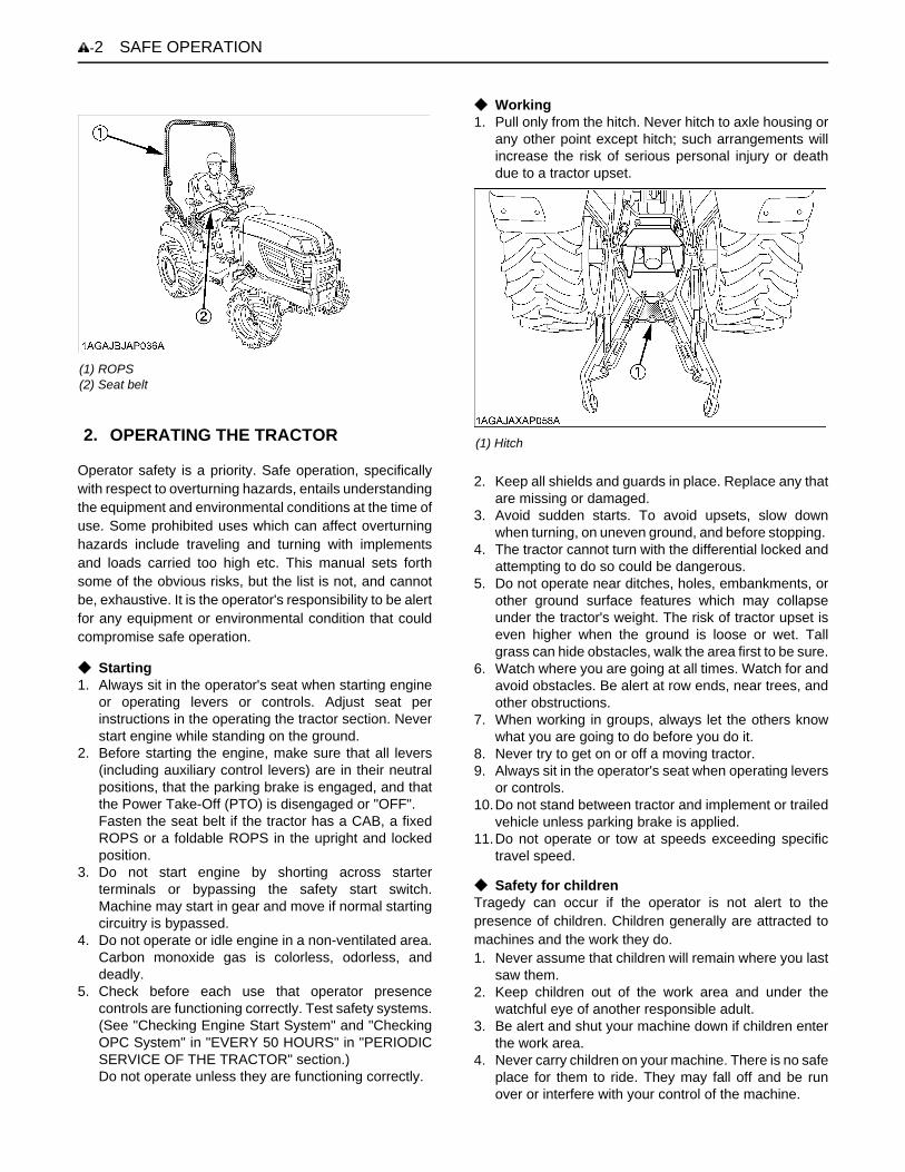
C Working1. Pull only from the hitch. Never hitch to axle housing or
any other point except hitch; such arrangements willincrease the risk of serious personal injury or deathdue to a tractor upset.
2. Keep all shields and guards in place. Replace any thatare missing or damaged.
3. Avoid sudden starts. To avoid upsets, slow downwhen turning, on uneven ground, and before stopping.
4. The tractor cannot turn with the differential locked andattempting to do so could be dangerous.
5. Do not operate near ditches, holes, embankments, orother ground surface features which may collapseunder the tractor's weight. The risk of tractor upset iseven higher when the ground is loose or wet. Tallgrass can hide obstacles, walk the area first to be sure.
6. Watch where you are going at all times. Watch for andavoid obstacles. Be alert at row ends, near trees, andother obstructions.
7. When working in groups, always let the others knowwhat you are going to do before you do it.
8. Never try to get on or off a moving tractor. 9. Always sit in the operator's seat when operating levers
or controls. 10.Do not stand between tractor and implement or trailed
vehicle unless parking brake is applied.11.Do not operate or tow at speeds exceeding specific
travel speed.
C Safety for childrenTragedy can occur if the operator is not alert to thepresence of children. Children generally are attracted tomachines and the work they do.1. Never assume that children will remain where you last
saw them.2. Keep children out of the work area and under the
watchful eye of another responsible adult.3. Be alert and shut your machine down if children enter
the work area.4. Never carry children on your machine. There is no safe
place for them to ride. They may fall off and be runover or interfere with your control of the machine.
(1) ROPS(2) Seat belt
2. OPERATING THE TRACTOR (1) Hitch

-3SAFE OPERATION
5. Never allow children to operate the machine evenunder adult supervision.
6. Never allow children to play on the machine or on theimplement.
7. Use extra caution when backing up. Look behind anddown to make sure area is clear before moving.
C Operating on slopesSlopes are a major factor related to loss-of-control and tip-over accidents, which can result in severe injury or death.All slopes require extra caution. 1. To avoid upsets, always back up steep slopes. If you
cannot back up the slope or if you feel uneasy on it, donot operate on it. Stay off slopes too steep for safeoperation.
2. Driving forward out of a ditch, mired condition or up asteep slope increases the risk of a tractor to be upsetbackward. Always back out of these situations. Extracaution is required with 4-wheel drive models becausetheir increased traction can give the operator falseconfidence in the tractor's ability to climb slopes.
3. Keep all movement on slopes slow and gradual. Donot make sudden changes in speed, direction or applybrake and make sudden motions of the steeringwheel.
4. Avoid changing gears speed when climbing or goingdown a slope. If on a slope changing gears to neutralcould cause loss of control.
5. Special attention should be made to the weight andlocation of implements and loads as such will affect thestability of the tractor.
6. To improve stability on slope, follow recommendationsfor proper ballasting as shown in "BALLAST" section.
C Driving the tractor on the road 1. Check the front wheel engagement. The braking
characteristics are different between 2 and 4-wheeldrive. Be aware of the difference and use carefully.
2. Always slow the tractor down before turning. Turningat high speed may tip the tractor over.
3. Make sure that the Slow Moving Vehicle (SMV) sign isclean and visible. Use hazard lights and turn signals asrequired.
4. On public roads use the SMV emblem and hazardlights, if required by local traffic and safety regulations.
5. Observe all local traffic and safety regulations. 6. Turn the headlights on.7. Drive at speeds that allow you to maintain control at all
times. 8. Do not apply the differential lock while traveling at road
speeds. The tractor may run out of control. 9. Avoid sudden motions of the steering wheel as they
can lead to a dangerous loss of stability. The risk isespecially great when the tractor is traveling at roadspeeds.
10.Keep the ROPS in the "UP" position and wear the seatbelt when driving the tractor on the road.Otherwise, you will not be protected in the event of atractor roll-over.
11.Do not operate an implement while the tractor is on theroad. Lock the 3-point hitch in the raised position.
12.When towing other equipment, use a safety chain andplace an SMV emblem on it as well.
(1) SMV emblem(2) Bracket(3) Knob nut
(1) Safety chain

SAFE OPERATION-4
13.Set the implement lowering speed knob in the "LOCK"position to hold the implement in the raised position.
1. Disengage the PTO, lower all implements to theground, place all control levers in their neutralpositions, set the parking brake, stop the engine,remove the key from the ignition and lock the cab door(if equipped). Leaving transmission in gear with theengine stopped will not prevent tractor from rolling.
2. Make sure that the tractor has come to a completestop before dismounting.
3. Avoid parking on steep slopes, if at all possible park ona firm and level surface; if not, park across a slope andchock the wheels.Failure to comply with this warning may allow thetractor to move and could cause injury or death.
4. When parking your machine if at all possible park on afirm, flat and level surface; if not, park across a slope.Set the parking brake(s), lower the implements to theground, remove the key from the ignition and lock thecab door (if equipped) and chock the wheels.
1. Wait until all moving components have completelystopped before getting off the tractor, connecting,disconnecting, adjusting, cleaning, or servicing anyPTO driven equipment.
2. Keep the PTO shaft cover in place at all times.Replace the PTO shaft cap when the shaft is not inuse.
3. Before installing or using PTO driven equipment, readthe manufacturer's manual and review the safetylabels attached to the equipment.
4. When operating stationary PTO driven equipment,always apply the tractor parking brake and placechocks behind and in front of the rear wheels. Stayclear of all rotating parts. Never step over rotatingparts.
(1) 3-point hitch lowering speed knob (A) "FAST"(B) "SLOW"(C) "LOCK"
3. PARKING THE TRACTOR
(1) Brake pedal(2) Parking brake pedal
(A) "DEPRESS"(B) "PUSH DOWN (2) WHILE DEPRESSING (1)"
4. OPERATING THE PTO
(1) PTO Shaft cover(2) PTO Shaft cap
(A) "NORMAL POSITION"(B) "RAISED POSITION"

-5SAFE OPERATION
1. Use the 3-point hitch only with equipment designed for3-point hitch usage.
2. When using a 3-point hitch mounted implement, besure to install the proper counterbalance weight on thefront of the tractor.
3. When transporting on the road, set the implementlowering speed knob in the "LOCK" position to hold theimplement in the raised position.
4. To avoid injury from separation:Do not extend lift rod beyond the groove on thethreaded rod.
Before servicing the tractor, park it on a firm, flat and levelsurface, set the parking brake, lower all implements to theground, place the gear shift lever in neutral, stop theengine and remove the key. 1. Allow the tractor time to cool off before working on or
near the engine, muffler, radiator, etc. 2. Do not remove radiator cap while coolant is hot. When
cool, slowly rotate cap to the first stop and allowsufficient time for excess pressure to escape beforeremoving the cap completely. If the tractor has acoolant recovery tank, add coolant or water to the tank,not the radiator. (See "Checking Coolant Level" in"DAILY CHECK" in "PERIODIC SERVICE OF THETRACTOR" section.)
3. Always stop the engine before refueling. Avoid spillsand overfilling.
4. Do not smoke when working around battery or whenrefueling. Keep all sparks and flames away frombattery and fuel tank. The battery presents anexplosive hazard, because it gives off hydrogen andoxygen especially when recharging.
5. Before "jump starting" a dead battery, read and followall of the instructions. (See "JUMP STARTING" in"OPERATING THE ENGINE" section.)
6. Keep first aid kit and fire extinguisher handy at alltimes.
7. Disconnect the battery's ground cable before workingon or near electric components.
8. To avoid the possibility of battery explosion, do not useor charge the refillable type battery if the fluid level isbelow the LOWER (lower limit level) mark. Check thefluid level regularly and add distilled water as requiredso that the fluid level is between the UPPER andLOWER levels.
9. To avoid sparks from an accidental short circuit,always disconnect the battery's ground cable (-) firstand reconnect it last.
5. USING 3-POINT HITCH
(1) 3-point hitch lowering speed knob (A) "FAST"(B) "SLOW"(C) "LOCK"
(1) Groove
6. SERVICING THE TRACTOR
(1) Battery

SAFE OPERATION-6
10.Do not attempt to mount a tire on a rim. This should bedone by a qualified person with the proper equipment.
11.Always maintain the correct tire pressure. Do notinflate tires above the recommended pressure shownin the operator's manual.
12.Securely support the tractor when either changingwheels or adjusting the wheel tread width.
13.Make sure that wheel bolts have been tightened to thespecified torque.
14.Do not work under any hydraulically supporteddevices. They can settle, suddenly leak down, or beaccidentally lowered. If it is necessary to work undertractor or any machine elements for servicing oradjustment, securely support them with stands orsuitable blocking beforehand.
15.Escaping hydraulic fluid under pressure has sufficientforce to penetrate skin, causing serious personalinjury. Before disconnecting hydraulic lines, be sure torelease all residual pressure. Before applyingpressure to the hydraulic system, make sure that allconnections are tight and that all lines, pipes, andhoses are free of damage.
16.Fluid escaping from pinholes may be invisible. Do notuse hands to search for suspected leaks; use a pieceof cardboard or wood. Use of safety goggles or othereye protection is also highly recommended. If injuredby escaping fluid, see a medical doctor at once. Thisfluid will produce gangrene or severe allergic reaction.
17.Waste products such as used oil, fuel, hydraulic fluid,and batteries, can harm the environment, people, petsand wildlife. Please dispose properly.See your local Recycling Center or KUBOTA Dealer tolearn how to recycle or get rid of waste products.
(1) Cardboard(2) Hydraulic line(3) Magnifying glass

-7SAFE OPERATION
LOADERMost loader equipment accidents can be avoided by following simple safety precautions.These safety precautions, if followed at all times, will help you operate your loader safely.
1. Read and understand all instructions and precautionsfound in both the tractor and the loader operator'smanuals before using the loader.Lack of knowledge can lead to accidents.
2. It is the owner's responsibility to ensure that anyonewho will operate the loader reads this manual first andbecomes familiar with the safe operation of the loader.
3. For your safety, a ROPS with a seat belt is stronglyrecommended by KUBOTA in almost all applications.If your tractor has a foldable ROPS, fold it down onlywhen absolutely necessary and raise it up and lock itagain as soon as possible. Do not wear the seat beltwhen a foldable ROPS is down or a fixed ROPS isremoved. If you have any questions, consult your localKUBOTA dealer.Always use the seat belt when the tractor is equippedwith a ROPS. Never use the seat belt when the tractoris not equipped with a ROPS.
4. Visually check for hydraulic leaks and broken, missing,or malfunctioning parts.Make necessary repairs before operating.
5. Replace damaged or illegible safety labels. Seefollowing pages for required labels.
6. When the front loader is mounted on the tractor, enterand exit the operator's seat only from left side of thetractor.
7. Engage the loader control valve lock to preventaccidental actuation when the implement is not in useor during transport. Do not utilize the valve lock formachine maintenance or repair.
8. Assemble, remove and reinstall the loader only asdirected in this manual. Failure to do this could resultin serious personal injury or death.
1. Operate the loader only when properly seated at thecontrols. Do not operate from the ground.
2. Move and turn the tractor at low speeds.3. Never allow anyone to get under the loader bucket or
reach through the boom when the bucket is raised.4. Keep children, others and livestock away when
operating loader and tractor.5. Do not walk or work under a raised loader bucket or
attachment unless it is securely blocked and held inposition.
6. For tractor stability and operator safety, rear ballastmust be added to the 3-point hitch and to the rearwheels when using loader.
7. To increase stability adjust the rear wheels to thewidest setting that is suitable for your application.
8. Exercise extra caution when operating the loader witha raised bucket or attachment.
9. Do not lift or carry any person on the loader, in thebucket, or other attachment.
10.Avoid loose fill, rocks and holes. They can bedangerous for loader operation or movement.
11.Avoid overhead wires and obstacles when the loaderis raised. Contacting electric lines can causeelectrocution.
12.Gradually stop the loader boom when lowering orlifting.
13.Use caution when handling loose or shiftable loads.14.Using loaders for handling large, heavy, or shiftable
objects is not recommended without proper handlingattachments.
15.Handling large heavy objects can be extremelydangerous due to :A Danger of rolling the tractor over.A Danger of upending the tractor.A Danger of the object rolling or sliding down the
loader boom onto the operator.16. If you must perform this sort of work (item 15), protect
yourself by :A Never lift the load higher than necessary to clear
the ground.A Add rear ballast to the tractor to compensate for the
load or use rear implement.A Never lift large objects with equipment that may
permit them to roll back onto the operator.A Move slowly and carefully, avoiding rough terrain.
17.Never lift or pull a load from any point on the loader (orany attachments) with a chain, rope, or cable. Doingso could cause a rollover or serious damage to theloader.
1. BEFORE OPERATING THE LOADER 2. OPERATING THE LOADER

SAFE OPERATION-8
18.Be extra careful when operating the tractor on a slope,always operate up and down, never across the slope.Do not operate on steep slopes or unstable surfaces.
19.When operating another implement on a hillside, besure to remove the loader to reduce the risk of rollover.
20.Carry loader boom at a low position during transport.(You should be able to see over the bucket.)
21.Allow for the loader length when making turns.
1. When loader work is complete and parking or storing,choose flat and hard ground. Lower the loader boomto the ground, stop the engine, set the brakes andremove the key before leaving the tractor seat.
2. Make sure the detached loader is on stands and on ahard, level surface.
3. Before disconnecting hydraulic lines, relieve allhydraulic pressure by moving the controls.
4. Do not remove the loader from the tractor without anapproved bucket attached.
1. Always wear safety goggles when servicing orrepairing the machine.
2. Do not modify the loader. Unauthorized modificationmay affect the function of the loader, which may resultin personal injury.
3. Do not use the loader as a work platform or a jack tosupport the tractor for servicing or maintenance.Securely support the tractor or any machine elementswith stands or suitable blocking before workingunderneath.For your safety, do not work under any hydraulicallysupported devices. They can settle or suddenly leakdown or be accidentally lowered.
4. Escaping hydraulic oil under pressure can havesufficient force to penetrate the skin, causing seriouspersonal injury. Do not use hands to search forsuspected leaks. If injured by escaping fluid, obtainmedical treatment immediately.
5. Do not tamper with the relief valve setting. The reliefvalve is pre-set at the factory. Changing the settingcan cause overloading of the loader and tractor whichmay result in serious personal injury.
6. When servicing or replacing pins in cylinder ends,bucket, etc., always use a brass drift and hammer.Failure to do so could result in injury from flying metalfragments.
3. AFTER OPERATING THE LOADER
4. SERVICING THE LOADER

-9SAFE OPERATION
BACKHOEMost backhoe equipment accidents can be avoided by following simple safety precautions.These safety precautions, if followed at all times, will help you operate your backhoe safely.
1. Read and understand all precautions in this manualbefore service or operation. Allow only trainedpersonnel to operate or service this equipment.
2. It is the owner’s responsibility to ensure that anyonewho will operate the backhoe reads this manual firstand becomes familiar with the safe operation of thebackhoe.
3. For safe operation, check the mounting bolts fortightness and that the mount levers are in the rightposition before operation.
4. Never operate tractor with backhoe attached andloader removed.
5. Check for buried material such as electrical,telephone, gas and water lines. When in doubt,contact local utility companies for their buried locationprior to operating the backhoe.
6. Replace any safety decal that becomes damaged, lostor illegible. Also renew all decals when repainting.
1. Do not allow anyone other than the operator on theunit while in operation or transport.
2. Keep all person and animals away from swing area ofbackhoe.
3. Use care when operating on slopes to avoid tip-over.Travel at a speed compatible with safe operation,especially when operating on uneven terrain, crossingditches or while turning.
4. Operate the backhoe from the backhoe operator's seatonly.
5. When using on slopes, one stabilizer may be lowerthan the other. Use extreme care during excavation asrisk of tip-over will increase.
6. To reduce the risk of tip-over on a slope, place thespoil to the high side of the excavation.
7. Do not dig under the stabilizer or tractor, especially insoft or sandy condition. Take extra precaution in wet orthawing ground.These conditions can become unstable and maycollapse under the weight of the machine and maycause tip over.
8. Never operate the machine or any equipment whileunder the influence of alcohol or other drugs, or whilefatigued.
9. When leaving the machine unattended, be sure tolower the backhoe to the ground. Set the parkingbrake, then shut the engine off and remove the key.
1. Raise and center the boom, close the dipperstick, curlthe bucket and engage the boom and swing locksbefore transporting the machine.
2. Check the local codes or regulations that may apply totractor / loader / backhoe operation on public streets orhighways, before transporting or traveling. Use SMVemblem and warning flashers as required.(SMV : Slow Moving Vehicle)
1. Before disconnecting hydraulic lines, relieve allhydraulic pressure by moving the controls.
2. Always use personal protection device such as safetygoggles and ear protection when servicing or repairingthe machine.
3. Lower the backhoe to the ground and shut the engineoff before servicing.
4. When servicing or repairing pins in cylinder ends,bucket, etc., always use a brass drift and hammer.Failure to do so could result in injury from flying metalfragments.
5. To avoid serious personal injury, keep clear of workingarea of the backhoe.
6. When servicing or checking underneath, do not getunder the machine while it is being held with only thebucket, backhoe or stabilizers. Securely support withjack stands.
7. For your safety, do not work under any hydraulicallysupported machine elements. They can settle,suddenly leak down, or be accidentally lowered.
8. Escaping hydraulic fluid under pressure can havesufficient force to penetrate the skin, causing seriouspersonal injury. Before applying pressure to thesystem, be sure that all connections are tight and thatlines, pipes and hoses are not damaged. Fluidescaping from a very small hole can be almostinvisible. Do not use hands to search for suspectedleaks, use a piece of cardboard or wood. If injured byescaping fluid, see a doctor at once. Serious infectionor allergic reaction will develop if proper medicaltreatment is not administered immediately.
9. Do not tamper with any backhoe control valve reliefpressure setting. The relief valve pressure is preset atthe factory. Changing the setting can causeoverloading of the backhoe and the tractor, andserious personal injury or death may result.
10.Do not modify the backhoe for any reason. Modifyingthe backhoe can cause an unstable condition of thetractor / loader / backhoe combination and seriouspersonal injury or death may result.
1. BEFORE OPERATING BACKHOE
2. OPERATING THE BACKHOE
3. DRIVING THE TRACTOR ON THE ROAD
4. SERVICING THE BACKHOE

SAFE OPERATION-10

-11SAFE OPERATION

SAFE OPERATION-12

-13SAFE OPERATION

SAFE OPERATION-14

-15SAFE OPERATION

SAFE OPERATION-16

-17SAFE OPERATION
1. Keep danger, warning and caution labels clean and free from obstructing material.2. Clean danger, warning and caution labels with soap and water, dry with a soft cloth.3. Replace damaged or missing danger, warning and caution labels with new labels from your local KUBOTA Dealer.4. If a component with danger, warning and caution label(s) affixed is replaced with new part, make sure new label(s) is
(are) attached in the same location(s) as the replaced component.5. Mount new danger, warning and caution labels by applying on a clean dry surface and pressing any bubbles to outside
edge.
CARE OF DANGER, WARNING AND CAUTION LABELS


1SERVICING
SERVICING
Your dealer is interested in your new tractor, loader andbackhoe and has the desire to help you get the most valuefrom them. After reading this manual thoroughly, you willfind that you can do some of the regular maintenanceyourself.However, when in need of parts or major service, be sureto see your KUBOTA Dealer.For service, contact the KUBOTA Dealership from whichyou purchased your tractor or your local KUBOTA Dealer.When in need of parts, be prepared to give your dealer thetractor, engine, loader and backhoe serial number.Locate the serial numbers now and record them in thespace provided.Concerning the tractor and loader, the reference to lefthand and right hand used in this manual refers to theposition when standing at the rear of the unit and facingforward.
Concerning the backhoe, the reference to left hand andright hand used in this manual refers to the position whenseating at the operator's seat at backhoe position andfacing rearward of the tractor.
C WarrantyThis tractor is warranted under the KUBOTA LimitedExpress Warranty, a copy of which may be obtained fromyour selling dealer. No warranty shall, however, apply ifthe tractor has not been handled according to theinstruction given in the Operator's Manual even it is withinthe warranty period.
C Scrapping the tractor and its procedureTo put the tractor out of service, correctly follow the localrules and regulations of the country or territory where youscrap it. If you have questions, consult your localKUBOTA Dealer.
Type Serial No.
Tractor BX25DLB
ROPS
Engine D902
Loader LA240A
Backhoe BT602
Date of Purchase
Name of Dealer
(To be filled in by purchaser)
(1) Backhoe serial number
(1) Tractor identification plate(2) Tractor serial number
(1) Engine serial number

SERVICING2
A The loader serial number label (1) is attached to theinside of the boom.
(1) ROPS identification plate (ROPS serial No.)
(1) Loader serial number

3SPECIFICATIONS OF THE TRACTOR
SPECIFICATIONS OF THE TRACTOR
SPECIFICATION TABLEModel BX25DLB
PTO power *1 kW (HP) 13.2 (17.7)
Engine
Maker KUBOTA
Model D902
Type Indirect injection, vertical, water-cooled, 4-cycle diesel
Number of cylinders 3
Bore and stroke mm (in.) 72 x 73.6 (2.83 x 2.90)
Total displacement cm (cu. in.) 898 (54.8)
Engine gross power *2 kW (HP) 17.1 (23.0)
Rated revolution rpm 3200
Low idling revolution rpm 1350 to 1550
Maximum torque N-m (lbf-ft) 56.1 (41.4)
Battery 12V, RC: 80min, CCA: 540A
Fuel Diesel fuel No.2 [above -10 (14 )] Diesel fuel No.1 [below -10 (14 )]
Capacities
Fuel tank L (U.S.gals.) 25 (6.6)
Engine crankcase (with filter) L (U.S.qts.) 3.1 (3.3)
Engine coolant L (U.S.qts.) 2.7 (2.8)
Recovery tank L (U.S.qts.) 0.4 (0.4)
Transmission case L (U.S.gals.) 11.6 (3.1)
Dimensions
Overall length (without 3P) mm (in.) 2120 (83.5)
Overall length (with 3P) mm (in.) 2425 (95.5)
Overall width mm (in.) 1145 (45.1)
Overall height(with ROPS) mm (in.) 2215 (87.2)
mm (in.) 1255 (49.4) (Top of seat)
Wheel base mm (in.) 1400 (55.1)
Min. ground clearance mm (in.) 175 (6.9)
TreadFront mm (in.) 930 (36.6)
Rear mm (in.) 820 (32.2)
Weight (with ROPS) kg (lbs.) 720 (1587)
Clutch N / A
Traveling system
TireFront 18 x 8.50-10 (Turf, Bar, Ind.)
Rear 26 x 12.00-12 (Turf, Bar, Ind.)
Steering Hydrostatic type power steering
Transmission Main: Hydrostatic transmission, High-Low gear shift (2 forward, 2 reverse)
Brake Wet disk type
Min. turning radius m (feet) 2.3 (7.5)

4 SPECIFICATIONS OF THE TRACTOR
The company reserve the right to change the specifications without notice.NOTE: *1 Manufacturer's estimate *2 SAE J1995 *3 See and check "IMPLEMENT LIMITATIONS."
TRAVELING SPEEDS (At rated engine rpm)
The company reserves the right to change the specifications without notice.
Hydraulic unit
Hydraulic control system Directional control, auto-return lever system
Pump capacity L/min. (gals/min.) 23.5 (6.2)
System pressure MPa (kgf/cm )[psi] 12.3 to 12.8 (126 to 130) [1790 to 1850]
Three point hitch SAE Category 1
Three point hitch Max. lift force *3
At lift points N (lbs.) 5390 (1210)
24in. behind lift points N (lbs.)
3040 (680)
Remote control valve coupler (rear : Opton)
System 2 valves
Coupler ISO 7341 series A
Remote control valve coupler (front : Opton)
System 2 valves
Coupler (nipple) ISO 7241-1 series B
PTO
Rear PTOSAE 1-3/8, 6 splines
Revolution 1 speed (540 rpm at 3142 engine rpm)
MID-PTOUSA No.5 (KUBOTA 10-tooth) involute spline
Revolution 1 speed (2500 rpm at 3043 engine rpm)
Model BX25DLB
Tire size (Rear) 26 X 12.00 - 12
Speed control pedal Range gear shift lever km / h mph
ForwardLow 0 to 6.5 0 to 4.0
High 0 to 13.5 0 to 8.4
ReverseLow 0 to 5.0 0 to 3.1
High 0 to 10.5 0 to 6.5
Model BX25DLB

5SPECIFICATIONS OF THE LOADER
SPECIFICATIONS OF THE LOADER
LOADER SPECIFICATIONSBUCKET SPECIFICATIONS
LOADER MODEL LA240A
TRACTOR MODEL BX25DLB
BOOM CYLINDERBORE mm (in.) 40 (1.57)
STROKE mm (in.) 326 (12.8)
BUCKET CYLINDERBORE mm (in.) 65 (2.56)
STROKE mm (in.) 204 (8.03)
CONTROL VALVEOne Detent Float Position, Two Stage Bucket Dump,
Power Beyond Circuit
RATED FLOW L/m (GPM) 14 (3.7)
MAXIMUM PRESSURE MPa (kg/cm , psi) 12.3 (125, 1780)
NET WEIGHT (APPROXIMATE) kg (lbs.) 170 (375)
LOADER MODEL LA240A
MODEL SQUARE 48"
TYPE RIGID
WIDTH mm (in.) 1219 (48.0)
DEPTH (L) mm (in.) 495 (19.5)
HEIGHT (M) mm (in.) 465 (18.3)
LENGTH (N) mm (in.) 538 (21.2)
CAPACITYSTRUCK m (CU.FT.) 0.14 (4.9)
HEAPED m (CU.FT.) 0.17 (6.0)
WEIGHT kg (lbs.) 60 (132)

6 SPECIFICATIONS OF THE LOADER
DIMENSIONAL SPECIFICATIONSLOADER MODEL LA240A
TRACTOR MODEL BX25DLB
A MAX. LIFT HEIGHT (TO BUCKET PIVOT PIN) mm (in.) 1810 (71.3)
B MAX. LIFT HEIGHT UNDER LEVEL BUCKET mm (in.) 1680 (66.1)
C CLEARANCE WITH BUCKET DUMPED mm (in.) 1330 (52.4)
DREACH AT MAX. LIFT HEIGHT(DUMPING REACH)
mm (in.) 660 (26.0)
E MAX. DUMP ANGLE deg. 45
F REACH WITH BUCKET ON GROUND mm (in.) 1390 (54.7)
G BUCKET ROLL-BACK ANGLE deg. 29
H DIGGING DEPTH mm (in.) 120 (4.7)
J OVERALL HEIGHT IN CARRYING POSITION mm (in.) 990 (39.0)
7SPECIFICATIONS OF THE LOADER
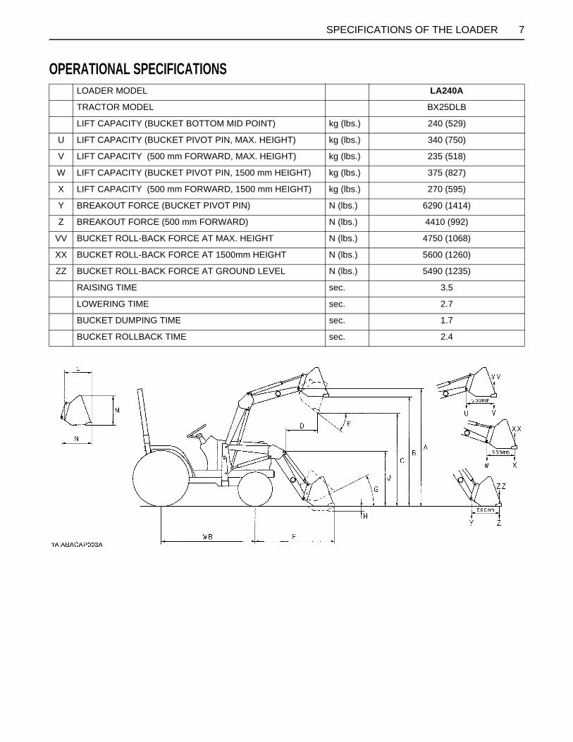
OPERATIONAL SPECIFICATIONSLOADER MODEL LA240A
TRACTOR MODEL BX25DLB
LIFT CAPACITY (BUCKET BOTTOM MID POINT) kg (lbs.) 240 (529)
U LIFT CAPACITY (BUCKET PIVOT PIN, MAX. HEIGHT) kg (lbs.) 340 (750)
V LIFT CAPACITY (500 mm FORWARD, MAX. HEIGHT) kg (lbs.) 235 (518)
W LIFT CAPACITY (BUCKET PIVOT PIN, 1500 mm HEIGHT) kg (lbs.) 375 (827)
X LIFT CAPACITY (500 mm FORWARD, 1500 mm HEIGHT) kg (lbs.) 270 (595)
Y BREAKOUT FORCE (BUCKET PIVOT PIN) N (lbs.) 6290 (1414)
Z BREAKOUT FORCE (500 mm FORWARD) N (lbs.) 4410 (992)
VV BUCKET ROLL-BACK FORCE AT MAX. HEIGHT N (lbs.) 4750 (1068)
XX BUCKET ROLL-BACK FORCE AT 1500mm HEIGHT N (lbs.) 5600 (1260)
ZZ BUCKET ROLL-BACK FORCE AT GROUND LEVEL N (lbs.) 5490 (1235)
RAISING TIME sec. 3.5
LOWERING TIME sec. 2.7
BUCKET DUMPING TIME sec. 1.7
BUCKET ROLLBACK TIME sec. 2.4

8 SPECIFICATIONS OF THE LOADER
[LA240A]
9SPECIFICATIONS OF THE LOADER
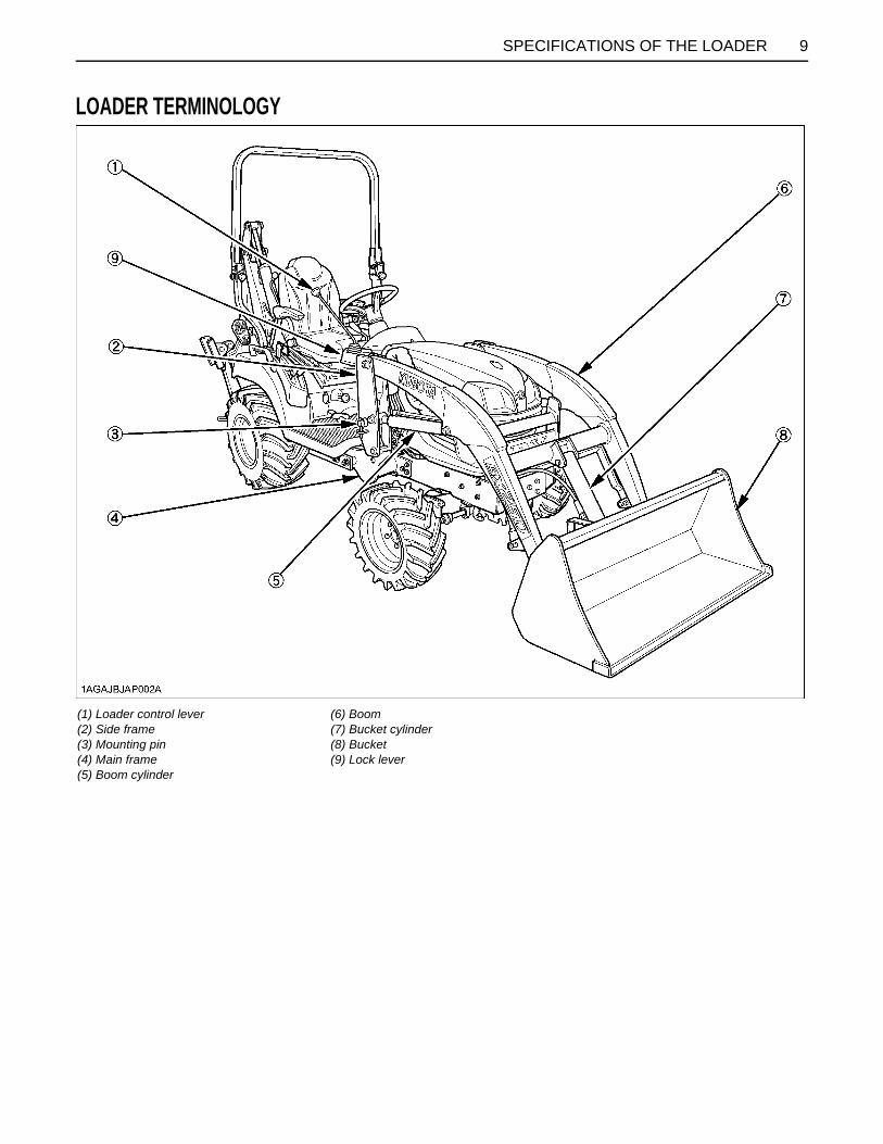
LOADER TERMINOLOGY
(1) Loader control lever(2) Side frame(3) Mounting pin(4) Main frame(5) Boom cylinder
(6) Boom(7) Bucket cylinder(8) Bucket(9) Lock lever

10 SPECIFICATIONS OF THE BACKHOE
SPECIFICATIONS OF THE BACKHOE
BACKHOE SPECIFICATIONSBDimensionsA The specifications are taken with KUBOTA BX25DLB tractor. (Tire size : Front 18 X 8.5-10, Rear 26 X 12.00-12)
Model BT602
Transport height (A) 1719 mm (67.7 in.)
Stabilizer spread-transport (B) 1296 mm (51.0 in.)
Ground clearance (C) 240 mm (9.4 in.)
Overall width (E) 1128 mm (44.4 in.)
Maximum digging depth (F) 1889 mm (74.4 in.)
Digging depth, 2 ft. flat bottom (G) 1842 mm (72.5 in.)
Digging depth, 8 ft. flat bottom (H) 1059 mm (41.7 in.)
Operating height, fully raised (J) 2539 mm (100 in.)
Loading height (K) 1533 mm (60.4 in.)
Loading reach (L) 1016 mm (40.0 in.)
Reach from swing pivot (M) 2612 mm (102.8 in.)
Swing pivot to rear axle center line (N) 726 mm (28.6 in.)
Bucket rotation (P) 180 deg.
Stabilizer spread-operating (R) 1862 mm (73.3 in.)
Angle of departure per SAE J1234 (A3) 20.1 deg.
Leveling angle (U) 11 deg.
Swing arc 140 deg.

11SPECIFICATIONS OF THE BACKHOE
BSpecificationsDigging force (Per SAE J49)
Cycle Time (seconds)
With bucket cylinder 8610 N (1936 lbs.)
With dipperstick cylinder 5209 N (1171 lbs.)
Boom cylinder, extend 4.5
Boom cylinder, retract 3.7
Swing cylinder, from 90 degrees to center 1.5
Dipperstick cylinder, extend 4.1
Dipperstick cylinder, retract 3.4
Bucket cylinder, extend 3.1
Bucket cylinder, retract 2.4
Stabilizer cylinder, max. height to ground 2.9
Stabilizer cylinder, ground to max. height 2.3

12 SPECIFICATIONS OF THE BACKHOE
Hydraulic cylinders
Bucket Sizes
Boomcm (in.)
Dipperstickcm (in.)
Bucketcm (in.)
Stabilizercm (in.)
Swingcm (in.)
Rod diameter 3.0 (1.18) 2.5 (0.98) 2.5 (0.98) 2.5 (0.98) 3.0 (1.18)
Cylinder bore 6.5 (2.56) 6.0 (2.36) 5.0 (1.97) 6.0 (2.36) 6.0 (2.36)
Widthcm (in.)
SAE truckCapacitym (cu-ft)
SAE HeapedCapacitym (cu-ft)
Numberof
Teeth
Weightkg (lbs)
Trenching 8" 20.3 (8) 0.009 (0.317) 0.011 (0.388) 2 10 (22)
Trenching 12" 30.5 (12) 0.014 (0.494) 0.020 (0.706) 3 13 (29)

13SPECIFICATIONS OF THE BACKHOE
BLift Capacity (Per SAE J31)Lift capacities shown are 87% of maximum lift force, according to SAE definition.
RATED LIFT CAPACITY(OVER END)-kg(lbs)
262(578)
214(472)
201(443)
203(448)
209(461)
215(474)
212(467)
192(423)
m(ft)
m(ft)
m(ft)
0.6(2)
1.2(4)
1.8(6)
0.6(2)
1.2(4)
1.8(6)
2.4(8)
1HNAAACAP002A
14 SPECIFICATIONS OF THE BACKHOE
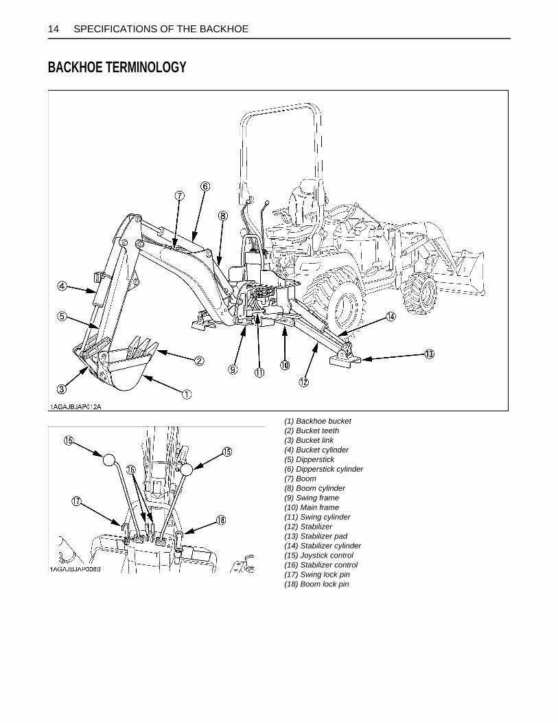
BACKHOE TERMINOLOGY
(1) Backhoe bucket(2) Bucket teeth(3) Bucket link(4) Bucket cylinder(5) Dipperstick(6) Dipperstick cylinder(7) Boom(8) Boom cylinder(9) Swing frame(10) Main frame(11) Swing cylinder(12) Stabilizer(13) Stabilizer pad(14) Stabilizer cylinder(15) Joystick control(16) Stabilizer control(17) Swing lock pin(18) Boom lock pin
15IMPLEMENT LIMITATIONS
IMPLEMENT LIMITATIONS
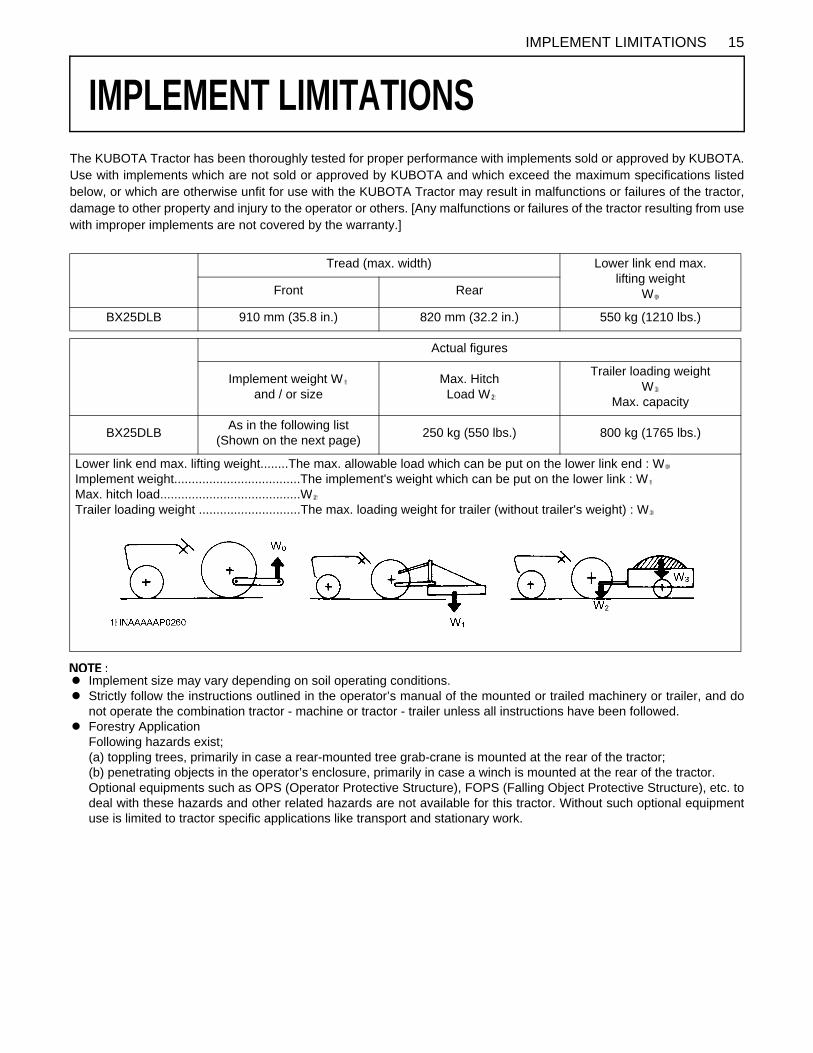
The KUBOTA Tractor has been thoroughly tested for proper performance with implements sold or approved by KUBOTA.Use with implements which are not sold or approved by KUBOTA and which exceed the maximum specifications listedbelow, or which are otherwise unfit for use with the KUBOTA Tractor may result in malfunctions or failures of the tractor,damage to other property and injury to the operator or others. [Any malfunctions or failures of the tractor resulting from usewith improper implements are not covered by the warranty.]A Implement size may vary depending on soil operating conditions.A Strictly follow the instructions outlined in the operator’s manual of the mounted or trailed machinery or trailer, and do
not operate the combination tractor - machine or tractor - trailer unless all instructions have been followed.A Forestry Application
Following hazards exist;(a) toppling trees, primarily in case a rear-mounted tree grab-crane is mounted at the rear of the tractor;(b) penetrating objects in the operator’s enclosure, primarily in case a winch is mounted at the rear of the tractor.Optional equipments such as OPS (Operator Protective Structure), FOPS (Falling Object Protective Structure), etc. todeal with these hazards and other related hazards are not available for this tractor. Without such optional equipmentuse is limited to tractor specific applications like transport and stationary work.
Tread (max. width) Lower link end max. lifting weight
WFront Rear
BX25DLB 910 mm (35.8 in.) 820 mm (32.2 in.) 550 kg (1210 lbs.)
Actual figures
Implement weight Wand / or size
Max. Hitch Load W
Trailer loading weight W
Max. capacity
BX25DLBAs in the following list
(Shown on the next page)250 kg (550 lbs.) 800 kg (1765 lbs.)
Lower link end max. lifting weight........The max. allowable load which can be put on the lower link end : WImplement weight....................................The implement's weight which can be put on the lower link : WMax. hitch load........................................WTrailer loading weight .............................The max. loading weight for trailer (without trailer's weight) : W

16 IMPLEMENT LIMITATIONS
*1 KUBOTA provides BT602 Backhoe for BX25DLB. No other Backhoe installed by 3-point hitch is permitted for BX25DLB.*2 KUBOTA provides LA240A Front-end Loader for BX25DLB.*3 The value contains the weight of KUBOTA standard bucket.*4 Reduce speed and trailer loads when operating in slippery conditions or when operating on slopes and utilize front wheel drive.
A Implement size may vary depending on soil operating conditions.
Implement Remarks BX25DLB
Backhoe *1Max. Digging Depth mm(ft) 1840 (6)
Max. Weight kg(lbs.) 262 (578) w/o Bucket
Front-end loader *2
Max. lifting capacity kg(lbs.)(Bucket pivot pin, max. height) *3
340 (750)
Max. width cm(in.) 122 (48)
Sub frame Necessary
Mower
Mid-mountMax. cutting width cm(in.) 152 (60)
Max. weight kg(lbs.) 115 (254)
Rotary-Cutter(1 Blade)
Max. cutting width cm(in.) 107 (42)
Max. weight kg(lbs.) 140 (309)
Rear-mount(2 or 3 Blade)
Max. cutting width cm(in.) 152 (60)
Max. weight kg(lbs.) 140 (309)
Flail-mower Max. cutting width cm(in.) 107 (42)
Sickle bar Max. cutting width cm(in.) 122 (48)
Rotary tillerMax. tilling width cm(in.) 107 (42)
Max. weight kg(lbs.) 170 (375)
Bottom plow Max. size in. 14 x 1
Disc plow Max. size in. 22 x 1
Cultivator Max. size cm(in.) 122 (48)1 Row
Disc harrowMax. harrowing width cm(in.) 137 (54)
Max. weight kg(lbs.) 140 (309)
Sprayer Max. tank capacity L(U.S.gals.) 150 (40)
Front bladeMax. cutting width cm(in.) 152 (60)
Sub frame Necessary
Rear bladeMax. cutting width cm(in.) 152 (60)
Max. weight kg(lbs.) 160 (353)
Box bladeMax. cutting width cm(in.) 122 (48)
Max. weight kg(lbs.) 170 (375)
Snow blower (Front)Max. working width cm(in.) 127 (50)
Max. weight kg(lbs.) 160 (353)
Sub frame Necessary
Post hole digger Digging depth cm(in.) 114 (45)
Rotary broom Cleaning width cm(in.) 119 (47)
TrailerMax. load capacity kg(lbs.) 800 (1765) *4
Max. weight kg(lbs.) 1100 (2425)

17INSTRUMENT PANEL AND CONTROLS
INSTRUMENT PANEL AND CONTROLS
B Instrument Panel, Switches and Hand ControlsILLUSTRATED CONTENTS
(1) Easy Checker(TM)............................................... 23,36
(2) Tachometer.......................................................... 37
(3) Hazard light switch................................................ 31
(4) Turn signal light switch.......................................... 31
(5) Head light switch................................................... 31
(6) Fuel gauge........................................................... 36
(7) Coolant temperature gauge.................................. 36
(8) Hourmeter............................................................ 37
(9) Key switch............................................................ 23
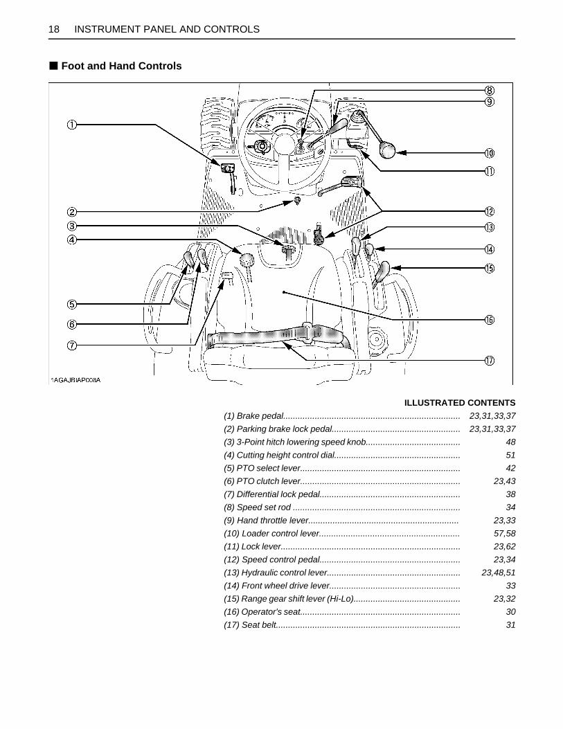
18 INSTRUMENT PANEL AND CONTROLS
B Foot and Hand Controls
ILLUSTRATED CONTENTS
(1) Brake pedal......................................................................... 23,31,33,37
(2) Parking brake lock pedal..................................................... 23,31,33,37
(3) 3-Point hitch lowering speed knob....................................... 48
(4) Cutting height control dial.................................................... 51
(5) PTO select lever.................................................................. 42
(6) PTO clutch lever.................................................................. 23,43
(7) Differential lock pedal.......................................................... 38
(8) Speed set rod ..................................................................... 34
(9) Hand throttle lever.............................................................. 23,33
(10) Loader control lever.......................................................... 57,58
(11) Lock lever.......................................................................... 23,62
(12) Speed control pedal.......................................................... 23,34
(13) Hydraulic control lever....................................................... 23,48,51
(14) Front wheel drive lever...................................................... 33
(15) Range gear shift lever (Hi-Lo)............................................ 23,32
(16) Operator's seat.................................................................. 30
(17) Seat belt............................................................................ 31

19PRE-OPERATION CHECK OF THE TRACTOR
PRE-OPERATION CHECK OF THE TRACTOR
DAILY CHECKTo prevent trouble from occurring, it is important to knowthe condition of the tractor well. Check it before starting.To avoid personal injury:A Be sure to check and service the tractor on a
level surface with the engine shut off and theparking brake "ON" and implement lowered tothe ground.
Check item- Walk around inspection- Check engine oil level- Check transmission oil level- Check coolant level- Clean grill and radiator screen- Check air cleaner evacuator valve (When used in a dusty place)- Check brake pedal- Check indicators, gauges and meter- Check lights- Check wire harness- Check seat belt and ROPS- Check movable parts- Refuel (See "DAILY CHECK" in "PERIODIC SERVICE OF THE TRACTOR" section.)- Care of danger, warning and caution labels (See "DANGER, WARNING AND CAUTION LABELS" in "SAFE OPERATION" section.)
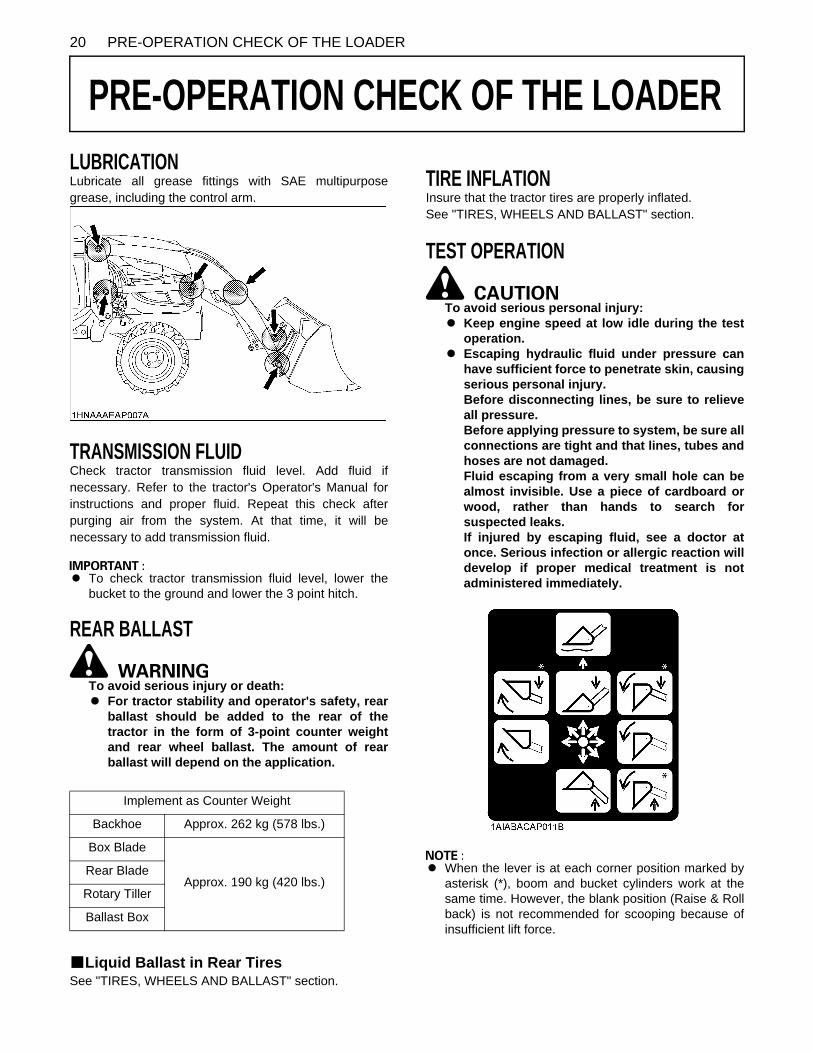
20 PRE-OPERATION CHECK OF THE LOADER
PRE-OPERATION CHECK OF THE LOADER
LUBRICATIONLubricate all grease fittings with SAE multipurposegrease, including the control arm.TRANSMISSION FLUIDCheck tractor transmission fluid level. Add fluid ifnecessary. Refer to the tractor's Operator's Manual forinstructions and proper fluid. Repeat this check afterpurging air from the system. At that time, it will benecessary to add transmission fluid.
A To check tractor transmission fluid level, lower thebucket to the ground and lower the 3 point hitch.
REAR BALLAST
To avoid serious injury or death:A For tractor stability and operator's safety, rear
ballast should be added to the rear of thetractor in the form of 3-point counter weightand rear wheel ballast. The amount of rearballast will depend on the application.
BLiquid Ballast in Rear TiresSee "TIRES, WHEELS AND BALLAST" section.
TIRE INFLATIONInsure that the tractor tires are properly inflated.See "TIRES, WHEELS AND BALLAST" section.
TEST OPERATION
To avoid serious personal injury:A Keep engine speed at low idle during the test
operation.A Escaping hydraulic fluid under pressure can
have sufficient force to penetrate skin, causingserious personal injury.Before disconnecting lines, be sure to relieveall pressure.Before applying pressure to system, be sure allconnections are tight and that lines, tubes andhoses are not damaged.Fluid escaping from a very small hole can bealmost invisible. Use a piece of cardboard orwood, rather than hands to search forsuspected leaks.If injured by escaping fluid, see a doctor atonce. Serious infection or allergic reaction willdevelop if proper medical treatment is notadministered immediately.
A When the lever is at each corner position marked byasterisk (*), boom and bucket cylinders work at thesame time. However, the blank position (Raise & Rollback) is not recommended for scooping because ofinsufficient lift force.
Implement as Counter Weight
Backhoe Approx. 262 kg (578 lbs.)
Box Blade
Approx. 190 kg (420 lbs.)Rear Blade
Rotary Tiller
Ballast Box

21PRE-OPERATION CHECK OF THE LOADER
To begin test operation, slightly move the control leverfrom "N" position. Slowly raise the loader boom justenough for the bucket to clear the ground when fullydumped. Slowly work through the dump and roll backcycles.
A If the boom or bucket does not work in the directionsindicated on the label, lower the bucket to the ground,stop the engine, and relieve all hydraulic pressure.Recheck and correct all hydraulic connections.
This control valve has 2 stage dump positions. The first"Regenerative" dump position, activated by moving thelever to the right, features high speed for efficient normalloader operations.The second "Regular" dump position, activated by movingthe lever further to the right, features increased power.This second position should be used when operatingimplements other than the loader with this control valve.These 2 positions are separated by a "Feel" position foryour convenience.
REMOVING AIR FROM HYDRAULIC SYSTEMRepeat raising and lowering the boom and bucketoperations until all the air is removed from the system andthe system responds properly.
A Do not move the control lever into float position whenthe bucket is off the ground.
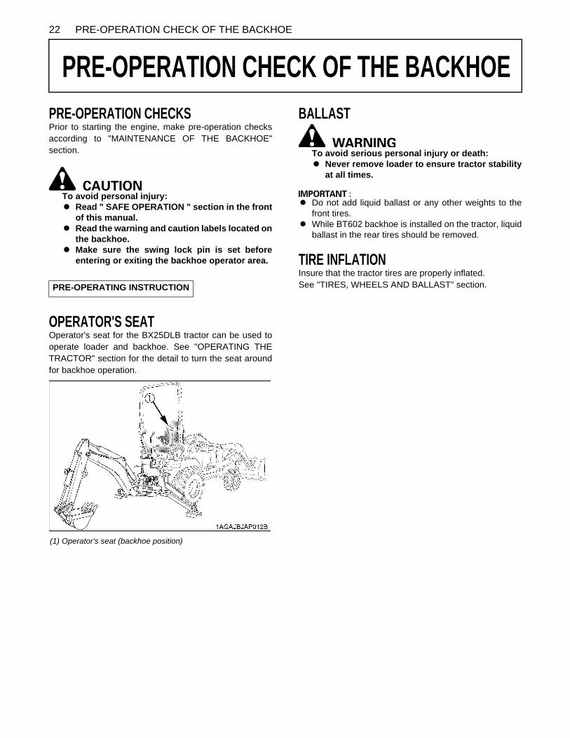
22 PRE-OPERATION CHECK OF THE BACKHOE
PRE-OPERATION CHECK OF THE BACKHOE
PRE-OPERATION CHECKSPrior to starting the engine, make pre-operation checksaccording to "MAINTENANCE OF THE BACKHOE"section.To avoid personal injury:A Read " SAFE OPERATION " section in the front
of this manual.A Read the warning and caution labels located on
the backhoe.A Make sure the swing lock pin is set before
entering or exiting the backhoe operator area.
OPERATOR'S SEATOperator's seat for the BX25DLB tractor can be used tooperate loader and backhoe. See "OPERATING THETRACTOR" section for the detail to turn the seat aroundfor backhoe operation.
BALLAST
To avoid serious personal injury or death:A Never remove loader to ensure tractor stability
at all times.
A Do not add liquid ballast or any other weights to thefront tires.
A While BT602 backhoe is installed on the tractor, liquidballast in the rear tires should be removed.
TIRE INFLATIONInsure that the tractor tires are properly inflated.See "TIRES, WHEELS AND BALLAST" section.PRE-OPERATING INSTRUCTION
(1) Operator's seat (backhoe position)

23OPERATING THE ENGINE
OPERATING THE ENGINE
To avoid personal injury:A Read "SAFE OPERATION" in the front of this
manual.A Read the danger, warning and caution labels
located on the tractor.A To avoid the danger of exhaust fume
poisoning, do not operate the engine in aclosed building without proper ventilation.
A Never start engine while standing on ground.Start engine only from operator's seat.
A Make it a rule to set all shift levers to"NEUTRAL" positions and to place PTO lever in"OFF" position before starting the engine.
A Do not use starting fluid or ether.A To protect the battery and the starter, make sure that
the starter is not continuously turned for more than 30seconds.
STARTING THE ENGINE
1. To set the parking brake;(1) Depress the brake pedal.(2) Latch the brake pedal on pushing and holding the
parking brake lock pedal then releasing pressureon the brake pedal.
2. To release the parking brake, depress the brake pedalagain.
A It is recommended that the operator practice engagingand disengaging the parking brake on a flat surfacewithout the engine running before operating the tractorfor the first time.
A The speed control pedal automatically return to"NEUTRAL" when the operator's foot is released fromthe pedal.
1. Make sure the parking brake is set.
(1) Brake pedal(2) Parking brake lock pedal
(A) "DEPRESS"(B) "PUSH DOWN (2) WHILE DEPRESSING (1)"
2. Place the PTO clutch lever in "OFF" position.
3. Place the speed set rod in "OFF" position. Place the speed control pedal in "NEUTRAL" position.Place the range gear shift lever (Hi-Lo) in "NEUTRAL" position.
(1) Speed set rod "ON"
"OFF"
(2) Speed control pedal(3) Range gear shift lever (Hi-Lo)
"Hi"(N) "NEUTRAL"
"Lo"(4) PTO clutch lever "ON"
"OFF"

OPERATING THE ENGINE24
To lower implement, move the hydraulic control leverforward.Check that implement is down at lowest position.
4. Lock the loader control lever in"NEUTRAL" position.
(1) Loader control lever(2) Lock lever
(A) "LOCK"
5. Move the hydraulic control leverforward. (With the implement in place.)
(1) Hydraulic control lever (A) "DOWN"
6. Set the throttle lever to about 1/2 way.
(1) Hand throttle lever "INCREASE" "DECREASE"
7. Insert the key into the key switch and turn it "ON".
"OFF""ON"
"PREHEAT" "START"

25OPERATING THE ENGINE
C Check Easy Checker(TM) Lamps:1. When the key is turned "ON", lamps (2) (3) (4) (5) (6)
only should come on. If trouble should occur at anylocation while the engine is running, the warning lampcorresponding to that location comes on.
A Daily checks with the Easy Checker(TM) only, are notsufficient. Never fail to conduct daily checks carefullyby referring to Daily Check section.(See "DAILY CHECK" in "PERIODIC SERVICE OFTHE TRACTOR" section.)
For the appropriate preheating time, refer to the tablebelow:
A Glow plug indicator (2) comes on while engine is beingpreheated.
A Because of safety devices, the engine will not startexcept when the speed control pedal is in "NEUTRAL"position and the PTO clutch lever is in "OFF" positionrespectively.
BCold Weather StartingWhen the ambient temperature is below -5 (23 ) andthe engine is very cold. If the engine fails to start after 10seconds, turn off the key for 30 seconds. Then repeatsteps 8 and 9. To protect the battery and the starter, makesure that the starter is not continuously turned for morethan 30 seconds.
BBlock Heater (Option)A block heater is available as an option from your dealer.It will assist you in starting your tractor when the ambienttemperature is below -15 (5 ).
If the lamp is still "ON", immediately stop the engine anddetermine the cause.
STOPPING THE ENGINE
A If key does not stop the engine, consult your localKUBOTA Dealer.
(1) Turn signal/Hazard light indicator(2) Preheat(3) Electrical charge(4) Engine oil pressure(5) Coolant temperature indicator(6) Low fuel indicator(7) Key switch
8. Turn the key to "PREHEAT" positionand hold it for about 2 to 3 seconds.
Temperature Preheating Time
Over 0 (32 ) 2 to 3 sec.
-5 to 0 (23 to 32 ) 5 sec.
-15 to -5 (5 to 23 ) 10 sec.
9. Turn the key to "START" position andrelease it when the engine starts.
10. Check to see that all the lamps on theEasy Checker(TM) are "OFF".
1. After slowing the engine to idle, turn the key to "OFF".
2. Remove the key.

OPERATING THE ENGINE26
WARMING UP
To avoid personal injury:A Be sure to set the parking brake during warm-
up.A Be sure to set all shift levers to "NEUTRAL"
positions and to place PTO lever in "OFF"position during warm-up.
For 5 minutes after engine start-up, allow engine to warmup without applying any load, this is to allow oil to reachevery engine part. If load should be applied to the enginewithout this warm-up period, trouble such as seizure,breakage or premature wear may develop.
BWarm-up and Transmission Oil in the Low Temperature Range
Hydraulic oil serves as transmission fluid. In cold weather,the oil may be cold with increased viscosity. This cancause delayed oil circulation or abnormally low hydraulicpressure for some time after engine start-up. This in turncan result in premature wear in the hydraulic system ormalfunctions such as resistance in the speed controlpedal and difficulty engaging the range gear shift lever. Toprevent the above, observe the following instructions:Warm up the engine at about 50% of rated rpm accordingto the table below:
A Do not operate the tractor under full load condition untilit is sufficiently warmed up.
JUMP STARTING
To avoid personal injury:A Battery gases can explode. Keep cigarettes,
sparks, and flames away from battery.A If tractor battery is frozen, do not jump start
engine.A Do not connect other end of negative (-) jumper
cable to negative (-) terminal of tractor battery.A When carrying on the following steps 4 and 11,
do not allow the positive (+) terminal of thebattery to touch other parts.
When jump starting engine, follow the instructions belowto safely start the engine.1. Bring helper vehicle with a battery of the same voltage
as disabled tractor within easy cable reach. "THEVEHICLES MUST NOT TOUCH".
2. Engage the parking brakes of both vehicles and putthe shift levers in "NEUTRAL". Shut both engines off.
3. Put on safety goggles and rubber gloves.4. Take the dead battery out and put it on the step.5. Ensure the vent caps are securely in place. (if
equipped)6. Attach the red clamp to the positive (red, (+) or pos.)
terminal of the dead battery and clamp the other endof the same cable to the positive (red, (+) or pos.)terminal of the helper battery.
7. Clamp the other cable to the negative (black, (-) orneg.) terminal of the helper battery.
8. Clamp the other end to the engine block or frame ofthe disabled tractor as far from the dead battery aspossible.
9. Start the helper vehicle and let its engine run for a fewmoments. Start the disabled tractor.
10.Disconnect the jumper cables in the exact reverseorder of attachment. (Steps 8, 7 and 6).
11.Put the battery back and fix it.
A This machine has a 12volt negative (-) ground startingsystem.
A Use only same voltage for jump starting.A Use of a higher voltage source on tractors electrical
system could result in severe damage to tractors electrical system.Use only matching voltage source when "Jumpstarting" a low or dead battery condition.
Ambient temperature Warm-up time requirement
Above 0 (32 ) At least 5 minutes
-10 to 0 (14 to 32 ) 5 to 10 minutes
-20 to -10 (-4 to 14 ) 10 to 15 minutes
Below -20 (-4 ) More than 15 minutes
(1) Dead battery(2) Jumper cables(3) Engine block or frame(4) Helper battery

27OPERATING THE TRACTOR
OPERATING THE TRACTOR
OPERATING NEW TRACTORHow a new tractor is handled and maintained determinesthe life of the tractor.A new tractor just off the factory production line has been,of course, tested, but the various parts are not broken in,so care should be taken to operate the tractor for the first50 hours at a slower speed and avoid excessive work oroperation until the various parts become "broken-in." Themanner in which the tractor is handled during the"breaking-in" period greatly affects the life of your tractor.Therefore, to obtain the maximum performance and thelongest life of the tractor, it is very important to properlybreak-in your tractor. In handling a new tractor, thefollowing precautions should be observed.BDo not Operate the Tractor at Full Speed for the First 50 Hours.
A Do not start quickly nor apply the brakes suddenly.A In winter, operate the tractor after fully warming up the
engine.A Do not run the engine at speeds faster than
necessary.A On rough roads, slow down to suitable speeds.
Do not operate the tractor at fast speed.The above precautions are not limited only to newtractors, but to all tractors. But it should be especiallyobserved in the case of new tractors.
BChanging Lubricating Oil for New TractorsThe lubricating oil is especially important in the case of anew tractor. The various parts are not "broken-in" and arenot accustomed to each other; small metal grit maydevelop during the operation of the tractor; and this maywear out or damage the parts. Therefore, care should betaken to change the lubricating oil a little earlier thanwould ordinarily be required.For further details of change interval hours, See"MAINTENANCE OF THE TRACTOR" section.
BOARDING AND LEAVING THE TRACTOR1. Never try to get on or off a moving tractor or jump off
the tractor to exit.2. Face the tractor when getting into or out of the tractor.
Do not use the controls as hand holds to preventinadvertent machine movements.
3. Always keep steps and floor clean to avoid slipperyconditions.
OPERATING FOLDABLE ROPS
To avoid personal injury:A When raising or folding the ROPS, apply
parking brake, stop the engine and remove thekey.Always perform function from a stable positionat the rear of tractor.
A Fold the ROPS down only when absolutelynecessary and fold it up and lock it again assoon as possible.
A Before proceeding to fold ROPS, check for anypossible interference with installedimplements and attachments.If interference occurs, contact your KUBOTADealer.
BTo Fold the ROPS1. Loosen the holding knob bolts.
(1) Holding Knob bolts
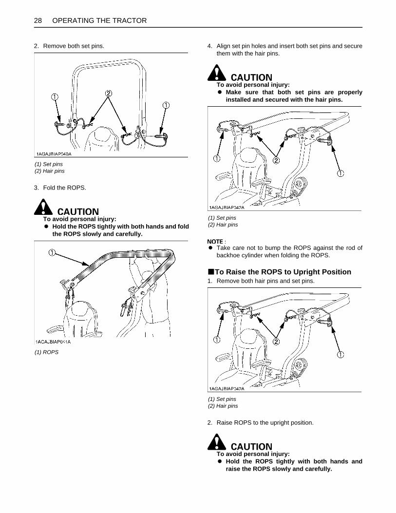
OPERATING THE TRACTOR28
2. Remove both set pins.
3. Fold the ROPS.
To avoid personal injury:A Hold the ROPS tightly with both hands and fold
the ROPS slowly and carefully.
4. Align set pin holes and insert both set pins and securethem with the hair pins.
To avoid personal injury:A Make sure that both set pins are properly
installed and secured with the hair pins.
A Take care not to bump the ROPS against the rod ofbackhoe cylinder when folding the ROPS.
BTo Raise the ROPS to Upright Position1. Remove both hair pins and set pins.
2. Raise ROPS to the upright position.
To avoid personal injury:A Hold the ROPS tightly with both hands and
raise the ROPS slowly and carefully.
(1) Set pins(2) Hair pins
(1) ROPS
(1) Set pins(2) Hair pins
(1) Set pins(2) Hair pins

29OPERATING THE TRACTOR
3. Align set pin holes, insert both set pins. Secure themwith the hair pins.
To avoid personal injury:A Make sure that both set pins are properly
installed as soon as the ROPS is in the uprightposition and secured with the hair pins.
4. Tighten the holding knob bolts.
BAdjustment of Foldable ROPSA Adjust free fall of the ROPS upper frame regularly.A If you feel less friction in folding the ROPS, tighten the
nut (1) until you feel the right friction in the movement.
(1) Set pins(2) Hair pins
(1) Holding knob bolts
(1) Nut

OPERATING THE TRACTOR30
STARTING
A The seat and suspension should be adjusted toensure that the controls are comfortably at hand for theoperator, ensuring that the operator maintains a goodposture.
BOperator's Seat
To avoid personal injury or death:A Make adjustments to the seat only while the
tractor is stopped.A Make sure that the seat is completely secured
after each adjustment.A Do not allow any person other than the
operator to ride on the tractor.
C Travel adjustmentPull up the position adjust lever and slide the seatbackward or forward, as required. The seat will lock inposition when the lever is released.
C Tilt adjustmentPull the backrest tilt adjust lever and tilt the backrest to thedesired position.
A After adjusting the operator's seat, be sure to checkthat the seat is properly locked.
A Be sure the operator's seat is out of contact with thetop link.
A See "REVERSING THE SEAT" section when usingseat in backhoe position.
1. Adjust the operator's position and engage the seat belt.
(A) "TRACTOR DRIVING POSITION"(B) "BACKHOE POSITION" (1) Seat
(2) Position adjust lever(3) Backrest tilt adjust lever(4) Arm rest(5) Seat belt
(A) "PULL UP"(B) "PULL"

31OPERATING THE TRACTOR
BSeat Belt
To avoid personal injury:A Always use the seat belt when the ROPS is
installed.Do not use the seat belt if a foldable ROPS isdown or there is no ROPS.
Adjust the seat belt for proper fit and connect to thebuckle. The seat belt is auto-locking retractable type.
BHead Light Switch(A) ...... Head lights "ON".(B) ...... Head lights "OFF".
BHazard Light SwitchWhen hazard light switch is turned counter-clockwise, thehazard lights flash along with the indicator on theinstrument panel. Turn the switch clockwise to turn off thelight.(A) ...... Hazard lights "ON".(B) ...... Hazard lights "OFF".
BTurn Signal Light SwitchTo indicate a right turn, turn the switch clockwise.To indicate a left turn, turn the switch counter-clockwise.When the left or right turn signal is activated incombination with the hazard lights, the indicated turninglight will flash and the other will stay on.
A Be sure to return switch to center position after turning.
BBrake PedalMake sure to latch the brake pedal with the parking brakelock pedal. Use both right and left feet for the procedure.
To avoid personal injury:A An accident may occur if the tractor is
suddenly braked, such as by heavy towedloads shifting forward or loss of control.
A The braking characteristics are differentbetween 2 and 4-wheel drive. Be aware of thedifference and use carefully.
A When driving on icy, wet or loose surfaces,make sure the tractor is correctly ballasted toavoid skidding and loss of steering control.Operate at reduced speed.
(1) Seat belt
2. Select Light Switch Positions.
(1) Hazard light switch(2) Head light switch(3) Turn signal light switch
(A) "ON"(B) "OFF"(C) "RIGHT TURN"(D) "LEFT TURN"
3. Check the Brake Pedal.

OPERATING THE TRACTOR32
Move the hydraulic control lever rearward.
BRange Gear Shift Lever (Hi-Lo)The range gear shift can only be shifted when tractor iscompletely stopped.
To avoid personal injury:A Make sure the range shift lever is fully engaged
into "H" or "L" position before climbing ordescending a slope.
Do not force the range gear shift lever.A If it is difficult to shift the range shift lever into
"NEUTRAL" position;(1) Depress the brake pedal firmly for several
seconds.(2) Without reducing the brake pedal force, shift the
range shift lever.A If it is difficult to shift the range shift lever into "L" or "H"
from "NEUTRAL" position;(1) Slightly depress the speed control pedal to rotate
the gears inside of transmission.(2) Release the speed control pedal to "NEUTRAL"
position.(3) Shift the range shift lever.
A To avoid damage of transmission, stop tractor beforeshifting between ranges.
(1) Brake pedal(2) Parking brake lock pedal
(A) "DEPRESS"(B) "PUSH DOWN (2) WHILE DEPRESSING (1)"
4. Start the engine.
5. Raise the Implement. (see "HYDRAULIC UNIT" section.)
(1) Hydraulic control lever "RAISED"(N) "NEUTRAL POSITION"
"LOWERED"
6. Select the Travel Speed.
(1) Range gear shift lever (Hi-Lo)
"HIGH"(N) "NEUTRAL POSITION"
"LOW"

33OPERATING THE TRACTOR
BFront Wheel Drive Lever
To avoid personal injury:A Do not engage the front wheel drive when
traveling at road speed.A When driving on icy, wet or loose surfaces,
make sure the tractor is correctly ballasted toavoid skidding and loss of steering control.Operate at reduced speed and engage frontwheel drive.
A An accident may occur if the tractor issuddenly braked, such as by heavy towedloads shifting forward or loss of control.
A The braking characteristics are differentbetween 2 and 4-wheel drive. Be aware of thedifference and use carefully.
Use the lever to engage the front wheels with the tractorstopped. Shift the lever to "ON" to engage the front wheeldrive.
A To avoid damage of transmission, when front wheeldrive lever is not smoothly shifted, slightly step forwardor rearward on speed control pedal.
A Tires will wear quickly if front wheel drive is engagedon paved roads.
C Front wheel drive is effective for the followingjobs:
1. When greater pulling force is needed, such as workingin a wet field, when pulling a trailer, or when workingwith a front-end loader.
2. When working in sandy soil.3. When working on a hard soil where a rotary tiller might
push the tractor forward.4. Additional braking at reduced speeds.
BHand Throttle LeverPulling the throttle lever back increases engine speed,and pushing it forward decreases engine speed.
BParking Brake PedalTo release the parking brake, depress the brake pedalagain.
(1) Front wheel drive lever "ON" "OFF"
7. Accelerate the Engine.
(1) Hand Throttle lever "INCREASE" "DECREASE"
8. Unlock the Parking Brake.
(1) Brake pedal
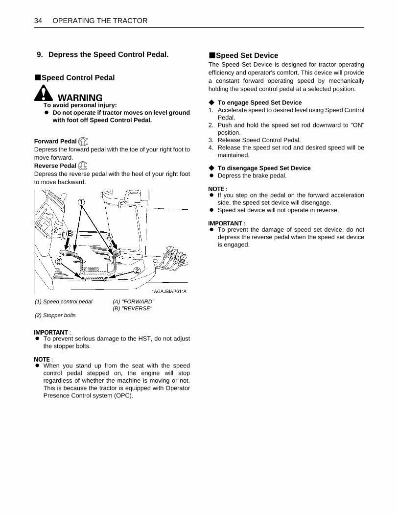
OPERATING THE TRACTOR34
BSpeed Control Pedal
To avoid personal injury:A Do not operate if tractor moves on level ground
with foot off Speed Control Pedal.
Forward Pedal Depress the forward pedal with the toe of your right foot tomove forward.Reverse Pedal Depress the reverse pedal with the heel of your right footto move backward.
A To prevent serious damage to the HST, do not adjustthe stopper bolts.
A When you stand up from the seat with the speedcontrol pedal stepped on, the engine will stopregardless of whether the machine is moving or not.This is because the tractor is equipped with OperatorPresence Control system (OPC).
BSpeed Set DeviceThe Speed Set Device is designed for tractor operatingefficiency and operator's comfort. This device will providea constant forward operating speed by mechanicallyholding the speed control pedal at a selected position.
C To engage Speed Set Device1. Accelerate speed to desired level using Speed Control
Pedal.2. Push and hold the speed set rod downward to "ON"
position.3. Release Speed Control Pedal.4. Release the speed set rod and desired speed will be
maintained.
C To disengage Speed Set DeviceA Depress the brake pedal.
A If you step on the pedal on the forward accelerationside, the speed set device will disengage.
A Speed set device will not operate in reverse.
A To prevent the damage of speed set device, do notdepress the reverse pedal when the speed set deviceis engaged.
9. Depress the Speed Control Pedal.
(1) Speed control pedal
(2) Stopper bolts
(A) "FORWARD"(B) "REVERSE"
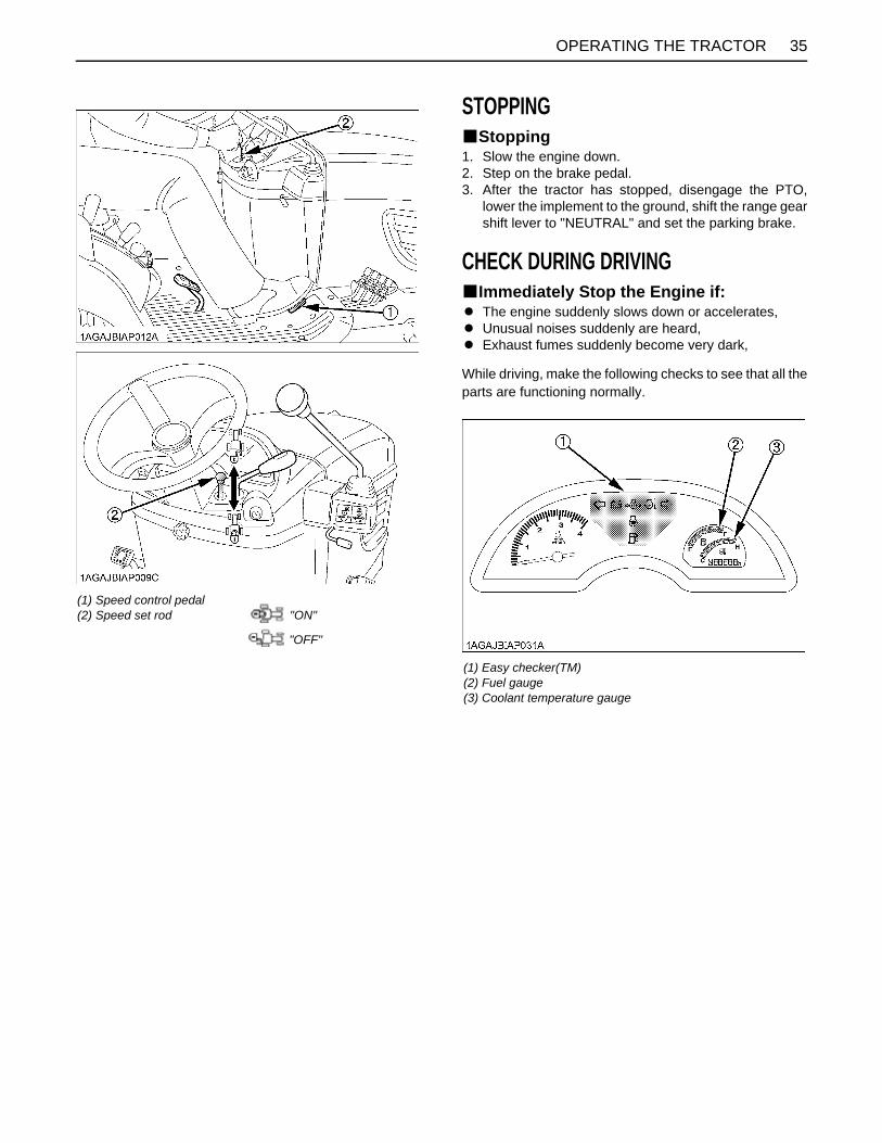
35OPERATING THE TRACTOR
STOPPINGBStopping1. Slow the engine down.2. Step on the brake pedal.3. After the tractor has stopped, disengage the PTO,
lower the implement to the ground, shift the range gearshift lever to "NEUTRAL" and set the parking brake.
CHECK DURING DRIVINGBImmediately Stop the Engine if:A The engine suddenly slows down or accelerates,A Unusual noises suddenly are heard,A Exhaust fumes suddenly become very dark,
While driving, make the following checks to see that all theparts are functioning normally.
(1) Speed control pedal(2) Speed set rod "ON"
"OFF"
(1) Easy checker(TM)(2) Fuel gauge(3) Coolant temperature gauge

OPERATING THE TRACTOR36
BEasy Checker(TM)If the warning lamps in the Easy Checker(TM) come onduring operation, immediately stop the engine, and findthe cause as shown below.Never operate the tractor while Easy Checker(TM) lamp is"ON".
A For checking and servicing of your tractor, consultyour local KUBOTA Dealer for instructions.
BFuel GaugeWhen the key switch is "ON", the fuel gauge indicates thefuel level.It's for the check if the gauge is working.When the fuel is close to empty level, the low fuel indicatorof the Easy Checker(TM) comes on and the segment K1of the fuel gauge starts blinking at 1-second intervals.Be careful not to empty the fuel tank. Otherwise air mayenter the fuel system.Should this happen, the system should be bled. (See"Bleeding Fuel System" in "SERVICE AS REQUIRED" in"PERIODIC SERVICE OF THE TRACTOR" section.)
BCoolant Temperature Gauge
To avoid personal injury:A Do not remove radiator cap until coolant
temperature is well below its boiling point.Then loosen cap slightly to the stop to relieveany pressure before removing cap completely.
Overheat indication:1. When the coolant temperature stays at 125 C (257 F)
for 5 seconds, the indicator on the Easy Checker(TM)comes on.
2. When the coolant temperature stays above 130 C(266 F) for 5 seconds, the indicator remains on and allsegments of the coolant temperature gauge startblinking at 1-second intervals.
3. When the coolant temperature stays below 120 C(248 F) for 5 seconds, the indicator turns off.
If the coolant temperature indicator on the EasyChecker(TM) comes on:1. Place the PTO clutch lever in "OFF" (DISENGAGE)
position.2. Move the machine to the level surface, and apply the
parking brake.3. Place the throttle lever in the engine idle position, and
let the engine run for a few minutes.4. Check the Cooling System, after it has sufficient time
to cool down.
Check the following items:1. Shortage or leakage of the coolant.2. Foreign matter on the radiator net or dust and dirt
between the radiator fins.3. Looseness of fan belt.4. Blockage in the radiator tube.
(See "PERIODIC SERVICE OF THE TRACTOR"section.)
Engine oil pressureIf the oil pressure in the engine goes below the prescribed level, the warning lamp in the Easy Checker(TM) will come on.If this should happen during operation, and it does not go off when the engine is accelerated to more than 1000 rpm, check level of engine oil.(See "Checking Engine Oil Level" in "DAILY CHECK" in "PERIODIC SERVICE OF THE TRACTOR" section.)
Electrical chargeIf the alternator is not charging the battery, the indicator in the Easy Checker(TM) will come on.If this should happen during operation, check the electrical charging system or consult your local KUBOTA Dealer.
(1) Fuel gauge (A) "EMPTY"(B) "FULL"(K1) Blinking segment

37OPERATING THE TRACTOR
BHourmeter/TachometerThe hourmeter indicates in 6 digits the hours the tractorhas been used; the last digit indicates 1/10 of an hour.When the key is turned "ON", the tachometer shouldindicate 4000 engine revolutions per minute (rpm) for justa moment.When the key switch is "ON" and the engine is "ON", thetachometer indicates the engine revolution per minute.
PARKINGBParking
To avoid personal injury or death:BEFORE DISMOUNTING TRACTORA ALWAYS SET PARKING BRAKE AND LOWER
ALL IMPLEMENTS TO THE GROUND.Leaving transmission in gear with the enginestopped will not prevent the tractor fromaccidental rolling.
A STOP THE ENGINE AND REMOVE THE KEY.
1. When parking, be sure to set the parking brake.To set the parking brake;(1) Depress the brake pedal.(2) Latch the brake pedal with the parking brake lock
pedal.
2. Before getting off the tractor, disengage the PTO,lower all implements to the ground, place all controllevers in their "NEUTRAL" positions, set the parkingbrake, stop the engine and remove the key.
3. If it is necessary to park on an incline, be sure to chockthe wheels to prevent accidental rolling of themachine.
(1) Coolant temperature gauge
(1) Hourmeter(2) Tachometer
(1) Brake pedal(2) Parking brake lock pedal
(A) "DEPRESS"(B) "PUSH DOWN (2) WHILE DEPRESSING (1)"

OPERATING THE TRACTOR38
ACCESSORYB12V Electric OutletAn auxiliary light or other devices may be connected tothis connector.
A Do not connect a light or other device that draws morethan 120 watts to this connector, or the battery maydischarge very rapidly or the outlet may fail.
A Do not use as a cigarette lighter.A Do not use when wet.
BGlove Box
OPERATING TECHNIQUESBDifferential Lock
To avoid personal injury due to loss of steeringcontrol:A Do not operate the tractor at high speed with
differential lock engaged.A Do not attempt to turn with the differential lock
engaged.A Be sure to release the differential lock before
making a turn in field conditions.
If one of the rear wheels should slip, step on thedifferential lock pedal. Both wheels will then turn together,reducing slippage.Differential lock is maintained only while the pedal isdepressed.
A When using the differential lock, always slow theengine down.
A To prevent damage to power train, do not engagedifferential lock when one wheel is spinning and theother is completely stopped.
A If the differential lock cannot be released in the abovemanner, alternately press speed control pedal forwardand backward slightly.
(1) 12V electric outlet
(1) Glove box
(1) Differential lock pedal (A) Press to "ENGAGE"(B) Release to "DISENGAGE"

39OPERATING THE TRACTOR
BOperating the Tractor on a Road
To avoid personal injury:A When traveling on road with 3-point hitch
mounted implement attached, be sure to havesufficient front weight on the tractor tomaintain steering ability.
Be sure SMV emblem and warning lamps are clean andvisible. If towed or rear-mounted equipment obstructsthese safety devices, install SMV emblem and warninglamps on equipment.Consult your local KUBOTA Dealer for further details.
1. Loosen the knob nut and turn the bracket verticallyand fasten the knob nut.
2. Set SMV emblem.
BOperating on a Slopes and Rough Terrain
To avoid personal injury:A Always back up when going up a steep slope.
Driving forward could cause the tractor to tipover backward. Stay off hills and slopes toosteep for safe operation.
A Avoid changing gears when climbing ordescending a slope.
A If operating on a slope, never disengage shiftlevers to "NEUTRAL". Doing so could causeloss of control.
A Do not drive the tractor close to the edges ofditches or banks which may collapse under theweight of the tractor. Especially when theground is loose or wet.
1. Slow down for slopes, rough ground, and sharp turns,especially when transporting heavy, rear mountedequipment.
2. Before descending a slope, be sure that the rangelever is in the low " " so that speed can becontrolled without using brakes.
BTransport the Tractor Safely1. The tractor, if damaged, must be carried on a truck.
Secure the tractor tightly with ropes.2. Follow the instruction below when towing the tractor:
Otherwise, the tractor’s powertrain may get damaged.A Set the all shift levers to "NEUTRAL" position.A If possible, start engine and select 2WD, if creep
speed is fitted ensure that it is disengaged.A Tow the tractor using its front hitch or drawbar.A Never tow faster than "10 km/h (6.2 mph)".
BDirections for Use of Power Steering1. Power steering is activated only while the engine is
running. While the engine is stopped, the tractorfunctions in the same manner as tractors withoutpower steering.
2. When the steering wheel is turned all the way to thestop, the relief valve is activated. Do not hold thesteering wheel in this position for a long period of time.
3. Avoid turning the steering wheel while the tractor isstopped, or tires may wear out sooner.
4. The power steering mechanism makes the steeringeasier. Be careful when driving on a road at highspeeds.
(1) SMV emblem(2) Bracket(3) Knob nut
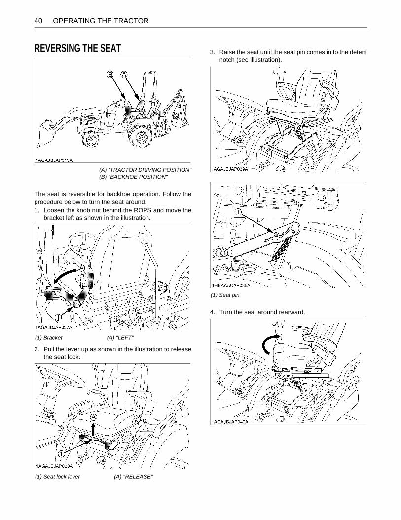
OPERATING THE TRACTOR40
REVERSING THE SEAT
The seat is reversible for backhoe operation. Follow theprocedure below to turn the seat around.1. Loosen the knob nut behind the ROPS and move the
bracket left as shown in the illustration.
2. Pull the lever up as shown in the illustration to releasethe seat lock.
3. Raise the seat until the seat pin comes in to the detentnotch (see illustration).
4. Turn the seat around rearward.
(A) "TRACTOR DRIVING POSITION"(B) "BACKHOE POSITION"
(1) Bracket (A) "LEFT"
(1) Seat lock lever (A) "RELEASE"
(1) Seat pin

41OPERATING THE TRACTOR
5. Push the seat backward, then the seat pin will comeout from detent notch.Push the seat down until the lever is locked at thebackhoe position.
A If the seat pin does not come out from the detentnotch, apply grease in the notch.
6. After reversing the operator's seat, be sure to check tosee that the seat is properly locked.
A Turn the seat at detent position to avoid damage ofseat locking mechanism and hitting to the range gearshift lever.
A See "Operator's Seat" section when using seat indriving position.
7. For tractor driving position, pull the lever up, and followthe reverse procedure mentioned above.
(1) Seat lock lever (A) "RELEASE"
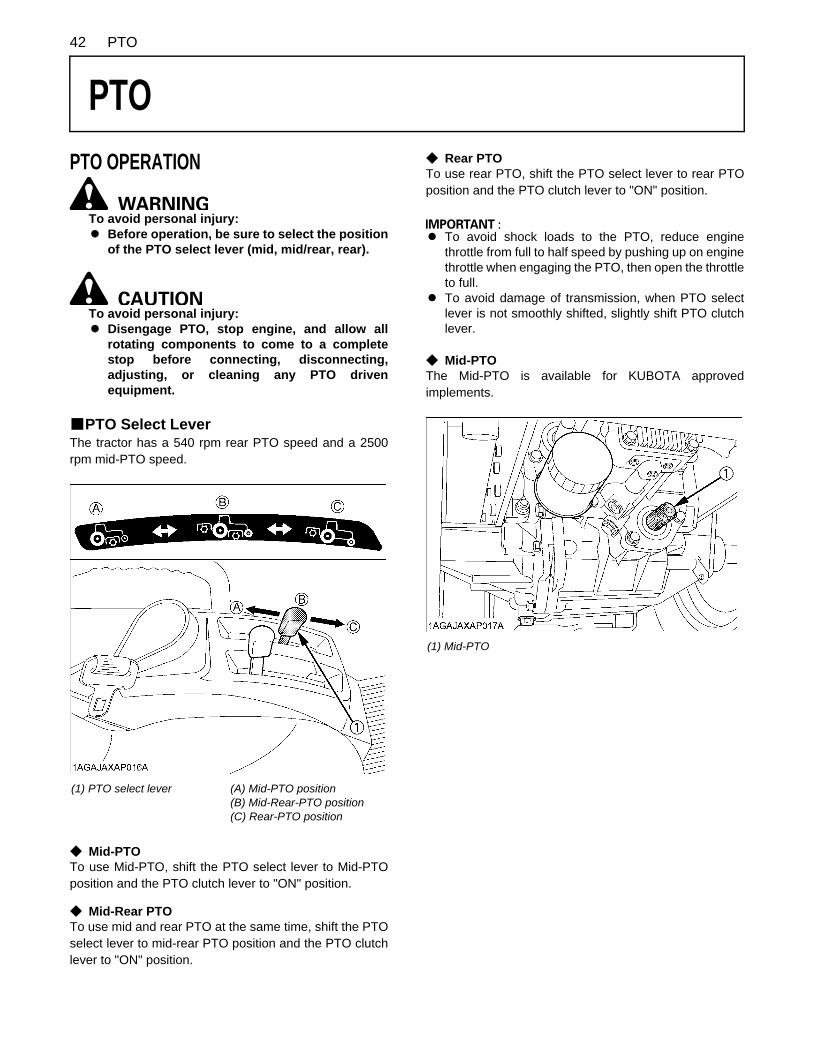
42 PTO
PTO
PTO OPERATIONTo avoid personal injury:A Before operation, be sure to select the position
of the PTO select lever (mid, mid/rear, rear).
To avoid personal injury:A Disengage PTO, stop engine, and allow all
rotating components to come to a completestop before connecting, disconnecting,adjusting, or cleaning any PTO drivenequipment.
BPTO Select LeverThe tractor has a 540 rpm rear PTO speed and a 2500rpm mid-PTO speed.
C Mid-PTOTo use Mid-PTO, shift the PTO select lever to Mid-PTOposition and the PTO clutch lever to "ON" position.
C Mid-Rear PTOTo use mid and rear PTO at the same time, shift the PTOselect lever to mid-rear PTO position and the PTO clutchlever to "ON" position.
C Rear PTOTo use rear PTO, shift the PTO select lever to rear PTOposition and the PTO clutch lever to "ON" position.
A To avoid shock loads to the PTO, reduce enginethrottle from full to half speed by pushing up on enginethrottle when engaging the PTO, then open the throttleto full.
A To avoid damage of transmission, when PTO selectlever is not smoothly shifted, slightly shift PTO clutchlever.
C Mid-PTOThe Mid-PTO is available for KUBOTA approvedimplements.
(1) PTO select lever (A) Mid-PTO position(B) Mid-Rear-PTO position(C) Rear-PTO position
(1) Mid-PTO

43PTO
BPTO Clutch Lever1. The PTO clutch lever engages or disengages the PTO
clutch which gives the PTO independent control.2. Shift the lever to "ON" to engage the PTO clutch. Shift
the lever to "OFF" to disengage the PTO clutch.
A To avoid shock loads to the PTO, reduce enginethrottle from full to half speed by pushing up on enginethrottle when engaging the PTO, then re-engage theengine to full.
A To avoid damage to PTO clutch and implement, shiftthe PTO clutch lever slowly, when engaging the PTOclutch. Do not keep the PTO clutch lever half way.
A Tractor engine will not start if the PTO clutch lever is inthe engaged "ON" position.
A When you stand up from the seat with the PTO clutchlever at "ON" (Engaged) position, the engine will stopregardless of the position of the PTO select lever.This is because the tractor is equipped with OperatorPresence Control system (OPC).
BPTO Shaft Cover and Shaft CapKeep the PTO shaft cover in place at all times. Replacethe PTO shaft cap when the PTO is not in use. Beforeconnecting or disconnecting a drive shaft to PTO shaft, besure engine is "OFF" and raise up the PTO shaft cover.Afterward be sure to return the PTO shaft cover to"NORMAL POSITION".
A The universal joint of the PTO drive shaft is technicallylimited in its moving angle. Refer to the PTO DriveShaft Instructions for proper use.
BStationary PTOTo park the tractor and use the PTO system (for chipperor pump, for example), start the PTO system in thefollowing steps.1. Apply the parking brakes and place blocks at the tires.2. Make sure all shift levers are at "NEUTRAL", and start
the engine.3. Set the PTO clutch lever to engage "ON".4. Set the engine speed to provide recommended rear
PTO speed.5. Unlock the seat lock lever and stand up and raise the
seat.
6. Turn the seat around rearward and lock the seat atbackhoe position. (See "REVERSING THE SEAT" in"OPERATING THE TRACTOR" section.)
(1) PTO clutch lever "ON" "ENGAGE" "OFF" "DISENGAGE"
(1) PTO shaft cover(2) PTO shaft cap
(A) "NORMAL POSITION"(B) "RAISED POSITION"
(1) Seat lock lever

PTO44
BPTO Drive Shaft
1. When using a PTO drive shaft, read the operator'smanual of the implement before operating theimplement.PTO drive shafts are designed for specific machinesand power requirement.
2. To adjust the length of the PTO drive shaft, refer to thefollowing instructions.(1) To adjust the length, hold the half shafts next to
each other in the shortest working position andmark them.
(2) Shorten inner and outer guard tubes equally.(3) Shorten inner and outer sliding profiles tube by
the same length as the guard tubes.(4) Round off all sharp edges and remove burrs.
Grease sliding profiles.
3. Ensure that the PTO drive shaft is securely connectedat both ends before operating.
(1) Inner and outer sliding profile tubes(2) Journal cross assy(3) Fitting yoke(4) Safety guard (In, Out)(5) Chain

453-POINT HITCH & DRAWBAR
3-POINT HITCH & DRAWBAR
Use holder plate to hold lower link higher while mowingwith mid-mount mower only over uneven terrain.
(1) Top link(2) Lifting rod (Left)(3) Check chains(4) Turnbuckle(5) Lower link(6) Top link holder(7) Lifting rod (Right)(8) Drawbar(9) Holder plate
(9) Holder plate
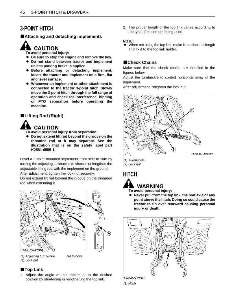
3-POINT HITCH & DRAWBAR46
3-POINT HITCHBAttaching and detaching implements
To avoid personal injury:A Be sure to stop the engine and remove the key.A Do not stand between tractor and implement
unless parking brake is applied.A Before attaching or detaching implement,
locate the tractor and implement on a firm, flatand level surface.
A Whenever an implement or other attachment isconnected to the tractor 3-point hitch, slowlymove the 3-point hitch through the full range ofoperation and check for interference, bindingor PTO separation before operating themachine.
BLifting Rod (Right)
To avoid personal injury from separation:A Do not extend lift rod beyond the groove on the
threaded rod or it may separate. See theillustration that is on the safety label partK2581-6555-1.
Level a 3-point mounted implement from side to side byturning the adjusting turnbuckle to shorten or lengthen theadjustable lifting rod with the implement on the ground.After adjustment, tighten the lock nut securely.Do not extend lift rod beyond the groove on the threadedrod when extending it.
BTop Link1. Adjust the angle of the implement to the desired
position by shortening or lengthening the top link.
2. The proper length of the top link varies according tothe type of implement being used.
A When not using the top link, make it the shortest lengthand fix it to the top link holder.
BCheck ChainsMake sure that the check chains are installed in thefigures below.Adjust the turnbuckle to control horizontal sway of theimplement.After adjustment, retighten the lock nut.
HITCH
To avoid personal injury:A Never pull from the top link, the rear axle or any
point above the hitch. Doing so could cause thetractor to tip over rearward causing personalinjury or death.
(1) Adjusting turnbuckle(2) Lock nut
(A) Groove
(1) Turnbuckle(2) Lock nut
(1) Hitch

473-POINT HITCH & DRAWBAR
BRemoving the 3-Point HitchWhen installing the backhoe, remove the 3-point hitch.1. Remove the lynch pin and the top link pin. Then
remove the top link.2. Remove the snap ring and the clevis pin. Then remove
the left and right lifting rod.
3. Remove the hair pin and stopper pin. Then remove thecheck chain plate and lower links.
BInstalling the 3-Point Hitch1. Follow the reverse procedure mentioned above.
(1) Top link(2) Clevis pin(3) Snap ring(4) Lifting rod (Left)(5) Lower link(6) Stopper pin
(7) Hair pin(8) Check chain plate(9) Top link pin(10) Lynch pin(11) Lifting rod (Right)
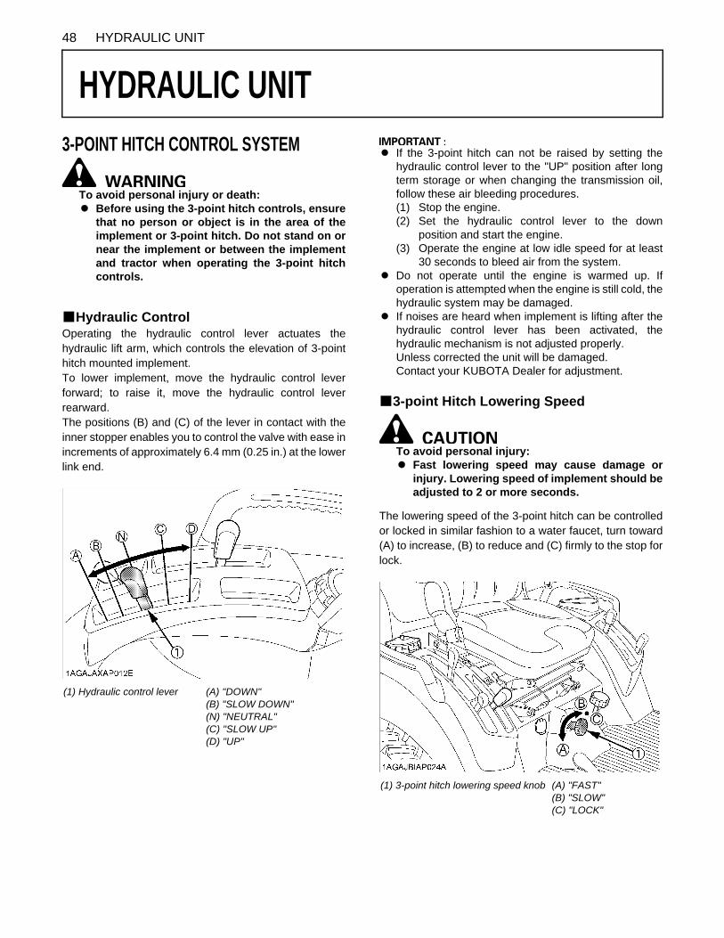
48 HYDRAULIC UNIT
HYDRAULIC UNIT
3-POINT HITCH CONTROL SYSTEMTo avoid personal injury or death:A Before using the 3-point hitch controls, ensure
that no person or object is in the area of theimplement or 3-point hitch. Do not stand on ornear the implement or between the implementand tractor when operating the 3-point hitchcontrols.
BHydraulic ControlOperating the hydraulic control lever actuates thehydraulic lift arm, which controls the elevation of 3-pointhitch mounted implement.To lower implement, move the hydraulic control leverforward; to raise it, move the hydraulic control leverrearward.The positions (B) and (C) of the lever in contact with theinner stopper enables you to control the valve with ease inincrements of approximately 6.4 mm (0.25 in.) at the lowerlink end.
A If the 3-point hitch can not be raised by setting thehydraulic control lever to the "UP" position after longterm storage or when changing the transmission oil,follow these air bleeding procedures.(1) Stop the engine.(2) Set the hydraulic control lever to the down
position and start the engine.(3) Operate the engine at low idle speed for at least
30 seconds to bleed air from the system.A Do not operate until the engine is warmed up. If
operation is attempted when the engine is still cold, thehydraulic system may be damaged.
A If noises are heard when implement is lifting after thehydraulic control lever has been activated, thehydraulic mechanism is not adjusted properly.Unless corrected the unit will be damaged.Contact your KUBOTA Dealer for adjustment.
B3-point Hitch Lowering Speed
To avoid personal injury:A Fast lowering speed may cause damage or
injury. Lowering speed of implement should beadjusted to 2 or more seconds.
The lowering speed of the 3-point hitch can be controlledor locked in similar fashion to a water faucet, turn toward(A) to increase, (B) to reduce and (C) firmly to the stop forlock.
(1) Hydraulic control lever (A) "DOWN"(B) "SLOW DOWN"(N) "NEUTRAL"(C) "SLOW UP"(D) "UP"
(1) 3-point hitch lowering speed knob (A) "FAST"(B) "SLOW"(C) "LOCK"

49HYDRAULIC UNIT
AUXILIARY HYDRAULICSOn the tractor hydraulic outlet is provided.
To avoid serious personal injury:A Escaping hydraulic fluid under pressure can
have sufficient force to penetrate skin, causingserious personal injury.Before disconnecting lines, be sure to relieveall pressure.Before applying pressure to system, be sure allconnections are tight and that lines, tubes andhoses are not damaged.Fluid escaping from a very small hole can bealmost invisible. Use a piece of cardboard orwood, rather than hands to search forsuspected leaks.If injured by escaping fluid, see a doctor atonce. Serious infection or allergic reaction willdevelop if proper medical treatment is notadministered immediately.
BHydraulic OutletIt can be used with the BT602 Backhoe.
When mounting the backhoe.1. Disconnect the coupler.
2. Route the implement inlet, outlet, and power beyondhose as shown in the illustration.
A For hydraulic outlet, be sure to use the control valve ofthe "Power beyond type" (with relief valve) and thirdline return to tank for the operation of hydraulic block.
(1) Coupler
(1) Inlet hose (backhoe)(2) Outlet hose (backhoe)(3) Power beyond hose (backhoe)(4) Outlet hose (tractor)(5) Return pipe (tractor)(6) Power beyond pipe (tractor)
(A) To Backhoe (outlet) Max. flow 14 L/min. (3.7 U.S.gals./min.)(B) From Backhoe (inlet)(C) Return to tank

HYDRAULIC UNIT50
INSTALLING MOWERDo not attach nor operate the mower with the backhoe stillin place.When installing the mower, remove the backhoe from thetractor with following procedure.
To avoid serious personal injury:A Escaping hydraulic fluid under pressure can
have sufficient force to penetrate skin, causingserious personal injury.Before disconnecting lines, be sure to relieveall pressure.Before applying pressure to system, be sure allconnections are tight and that lines, tubes andhoses are not damaged.Fluid escaping from a very small hole can bealmost invisible. Use a piece of cardboard orwood, rather than hands to search forsuspected leaks.If injured by escaping fluid, see a doctor atonce. Serious infection or allergic reaction willdevelop if proper medical treatment is notadministered immediately.
C Disconnecting and connecting the hoses1. Shut the engine off and set the parking brake.2. Tilt the operator's seat forward.3. Remove hydraulic pressure by moving the controls.4. Disconnect the backhoe inlet hose, outlet hose and
power beyond hose.
5. Place the protective cap on the coupler of the backhoeinlet hose, the coupler of the outlet hose, and powerbeyond hose.
6. Connect the tractor outlet hose to the coupler of powerbeyond pipe.
7. Place the protective cap on the nipple of the tractorreturn pipe.
A When getting ready to use the backhoe after finishingmowing, connect the hoses of the tractor and backhoein reverse order.
(1) Inlet hose (backhoe)(2) Outlet hose (backhoe)(3) Power beyond hose (backhoe)(4) Outlet hose (tractor)
(1) Outlet hose (tractor)(2) Power beyond pipe (tractor)
(A) To be connected
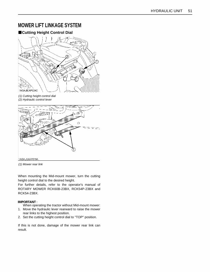
51HYDRAULIC UNIT
MOWER LIFT LINKAGE SYSTEMBCutting Height Control Dial
When mounting the Mid-mount mower, turn the cuttingheight control dial to the desired height.For further details, refer to the operator's manual ofROTARY MOWER RCK60B-23BX, RCK54P-23BX andRCK54-23BX.
When operating the tractor without Mid-mount mower:1. Move the hydraulic lever rearward to raise the mower
rear links to the highest position.2. Set the cutting height control dial to "TOP" position.
If this is not done, damage of the mower rear link canresult.
(1) Cutting height control dial(2) Hydraulic control lever
(1) Mower rear link

52 HYDRAULIC UNIT
BHydraulic Control Unit Use Reference ChartIn order to handle the hydraulics properly, the operator must be familiar with the following. Though this information may notbe applicable to all types of implements and soil conditions, it is useful for general conditions.
Implement
Soil condition(1) Hydraulic control lever Gauge wheel (1) Check chains
Remarks
Moldboard plowLight soilMedium soilHeavy soil
Hydraulic control
YES/NO Loose
Adjust the check chains so that the implement can move 5 to 6 cm (2.0 to 2.4 in.) laterally.Check chains should be tight enough to prevent excessive implement movement when implement is in raised position.
Disc plow ---
Harrower (spike, springtooth, disc type)
---
Sub-soiler......
Weeder, ridger.....
---
YES
Tighten
Earthmove, digger scraper, manure fork rear carrier....
YES/NO
For implements with gauge wheels, lower the position control lever all way.
Mower (mid-and rear-mount type) Hayrake, tedder...

53TIRES, WHEELS AND BALLAST
TIRES, WHEELS AND BALLAST
TIRESTo avoid personal injury:A Do not attempt to mount a tire on a rim. This
should be done by a qualified person with theproper equipment.
A Always maintain the correct tire pressure.Do not inflate tires above the recommendedpressure shown in the operator's manual.
A Do not use tires other than those approved byKUBOTA.
A When you intend to mount different size of tires fromequipped ones, consult your dealer about front drivegear ratio for details.Excessive wear of tires may occur due to impropergear ratio.
BInflation PressureThough the tire pressure is factory-set to the prescribedlevel, it naturally drops slowly in the course of time. Thus,check it everyday and inflate as necessary.
A Maintain the maximum pressure in front tires, if usinga front loader or when equipped with a full load of frontweight.
BDual TiresDual tires are not approved.
WHEEL TREAD
To avoid personal injury:A Support tractor securely on stands before
removing a wheel.A Never operate tractor with a loose rim, wheel,
or axle.
BFront WheelsFront tread can not be adjusted.
A Do not turn front discs to obtain wider tread.
Tire sizes Inflation Pressure
Rear26x12.00-12 Turf26x12.00-12 Bar26x12.00-12 Ind.
100kPa(1.0kgf/ ,14psi)120kPa(1.2kgf/ ,17psi)120kPa(1.2kgf/ ,17psi)
Front18x8.50-10 Turf18x8.50-10 Bar18x8.50-10 Ind.
120kPa(1.2kgf/ ,17psi)150kPa(1.5kgf/ ,22psi)150kPa(1.5kgf/ ,22psi)
Tire 18x8.50-10 Turf, Bar, and Ind.
Tread

TIRES, WHEELS AND BALLAST54
To avoid personal injury or death:A Before jacking up the tractor, park it on a firm
and level ground and chock the rear wheels.A Fix the front axle to keep it from pivoting.A Select jacks that withstand the machine weight
and set them up as shown below.
BRear WheelsRear tread width can not be adjusted.
A Do not turn rear discs to obtain wider tread.
A Always attach tires as shown in the drawings.A If not attached as illustrated, transmission parts may
be damaged. When re-fitting or adjusting a wheel,tighten the bolts to the following torques then recheckafter driving the tractor 200m (200yards), after one day(8 hours) and thereafter every 50 hours (as permaintenance chart).
A Use the tapered bolts for wheels with beveled ortapered holes.
To avoid personal injury:A Before jacking up the tractor, park it on a firm
and level ground and chock the front wheels.A Fix the front axle to keep it from swinging.A Select a jack that withstands the machine
weight and set it up as shown below.
(1) Front axle case(2) Jack points
Tire 26x12.00-12 Turf, Bar, and Ind.
Tread
(1) Bolt Front 149.2 to 179.0 N-m (15.2 to 18.3 kgf-m) (110 to 132 lbf-ft)Rear 108.5 to 130.2 N-m (11.1 to 13.3 kgf-m) (80 to 96 lbf-ft)
(1) Frame(2) Jack point

55TIRES, WHEELS AND BALLAST
BALLAST
To avoid personal injury:A Additional ballast will be needed for
transporting heavy implements. When theimplement is raised, drive slowly over roughground, regardless of how much ballast isused.
A Do not fill the front wheels with liquid tomaintain steering control.
A The ballast is not required when doing the normaloperations with the BX25DLB tractor, LA240A loaderand BT602 backhoe connected in factory settings.
BFront BallastAdd weights if needed for stability and improve traction.Heavy pulling and heavy rear mounted implements tendto lift front wheels. Add enough ballast to maintainsteering control and prevent tip over.Remove weight when no longer needed.
A Do not overload tires.A Add no more weight than indicated in chart.
BRear BallastAdd weight to rear wheels if needed to improve traction orfor stability. The amount of rear ballast should be matchedto job and the ballast should be removed when it is notneeded.The weight should be added to the tractor in the form ofliquid ballast.When the loader is attached on the tractor and thebackhoe is not, the rear wheel weight (option) should beinstalled to the tractor.
C Liquid Ballast in Rear TiresWater and calcium chloride solution provides safeeconomical ballast. Used properly, it will not damage tires,tubes or rims. The addition of calcium chloride isrecommended to prevent the water from freezing. Use ofthis method of weighting the wheels has the full approvalof the tire companies. See your tire dealer for this service.
Liquid weight per tire (75 Percent filled)
A When mounting a heavy implement, a liquid in the tiremay not be required.
A Do not fill tires with water or solution more than 75% offull capacity (to the level of valve stem at 12 o'clockposition).
A To avoid damage of transmission, do not use rearwheel weights and liquid ballast at the same time.
A Do not add liquid ballast or any other weights to thefront tires.
A While BT602 backhoe is installed on the tractor, liquidballast in the rear tires should be removed.
Maximum weight 125 kg (275 lbs.)
Tire sizes 26x12.00-12
Slush free at -10 (14 )Solid at -30 (-22 )[Approx. 1 kg (2 lbs.)
CaCl per 4 L (1 gal) of water]
45 kg(99 lbs.)
Slush free at -24 (-11 )Solid at -47 (-52 )
[Approx. 1.5 kg (3.5 lbs.)CaCl per 4 L (1 gal) of water]
50 kg(110 lbs.)
Slush free at -47 (-52 )Solid at -52 (-62 )
[Approx. 2.25 kg (5 lbs.)CaCl per 4 L (1 gal) of water]
56 kg(123 lbs.)
(1) Air(2) Water(3) Valve stem
(A) Correct : 75% Full Air compresses like a cushion(B) Incorrect : 100% Full Water can not be compressed

TIRES, WHEELS AND BALLAST56
C Rear Wheel Weight (option)The rear wheel weight can be installed to the 3-point hitch.Consult your local KUBOTA dealer to use.
A Besides the rear wheel weight, a three-point kit isrequired for installing the weight.
(1) Rear wheel weight

57OPERATING THE LOADER
OPERATING THE LOADER
The loader should be operated with the tractor enginespeed depending on the application and the operator'slevel of experience. Excessive speeds are dangerous,and may cause bucket spillage and unnecessary strain onthe tractor and loader.When operating in temperatures below -1 C(30 F), runthe tractor engine below 1200 rpm until the oiltemperature exceeds -1 C(30 F).The following text and illustrations offer suggested loaderand tractor operating techniques.To reduce the possibility of roll over:A It is not recommended that the loader be attached
when operating another implement on a hillside.
A When operating the loader in rough terrain, removethe mower to avoid damage to the mower.
FILLING THE BUCKETApproach and enter the pile with a level bucket.
Ease control lever toward you and then left to rollback andlift the bucket.
The rollback and lifting of the bucket will increaseefficiency because a level bucket throughout the liftingcycle resists bucket lift and increases breakaway effort.
A Do not be concerned if the bucket is not completelyfilled during each pass. Maximum productivity isdetermined by the amount of material loaded in agiven period of time. Time is lost if 2 or more attemptsare made to fill the bucket on each pass.
LIFTING THE LOADWhen lifting the load, keep the bucket positioned to avoidspillage.
To avoid serious personal injury:A Do not attempt to lift bucket loads in excess of the
loader capacity.A Before raising the bucket to full height, make sure
the tractor is on level ground. If not, it may tip over,even if the tractor is not moving.

OPERATING THE LOADER58
CARRYING THE LOADPosition the bucket just below the level of the tractor hoodfor maximum stability and visibility, whether the bucket isloaded or empty.
Use extreme care when operating the loader on a slope.Keep the bucket as low as possible. This keeps the bucketand tractor center of gravity low and will provide maximumtractor stability.
To avoid serious personal injury:A Be extra careful when working on inclines.A When operating on a slope, always operate up and
down the slope, never across the slope.
When transporting a load, keep the bucket as low aspossible to avoid tipping, in case a wheel drops in a rut.
DUMPING THE BUCKETLift the bucket just high enough to clear the side of thevehicle. Move the tractor in as close to the side of thevehicle as possible, then dump the bucket.
LOWERING THE BUCKETAfter the bucket is dumped, back away from the vehiclewhile lowering and rolling back the bucket.
OPERATING WITH FLOAT CONTROLDuring operation on hard surface, keep the bucket leveland put the lift control in the float position to permit thebucket to float on the working surface. If hydraulic downpressure is exerted on the bucket it will wear faster thannormal.
The float position will also avoid mixing of surface materialwith stockpile material. The float position will reduce thechance of surface gouging while removing snow or othermaterial, or when working with a blade.

59OPERATING THE LOADER
LOADING FROM A BANKChoose a forward gear that provides a safe ground speedand power for loading.
To avoid the possibility of serious personal injury:A Exercise caution when undercutting high banks.A Dirt slides can be dangerous. Load from as low as
possible for maximum efficiency.
A Loader lift and break-away capacity diminish asloading height is increased.
Side cutting is a good technique for cutting down a bigpile. Wheel width should not exceed the bucket width forthis procedure.
If the pile sides are too high and liable to cause cave-in,use the loader to break down the sides until a slot can becut over the top.
Another method for large dirt piles is to build a ramp toapproach the pile.
It is important to keep the bucket level when approachinga bank or pile. This will help avoid gouging the work area.
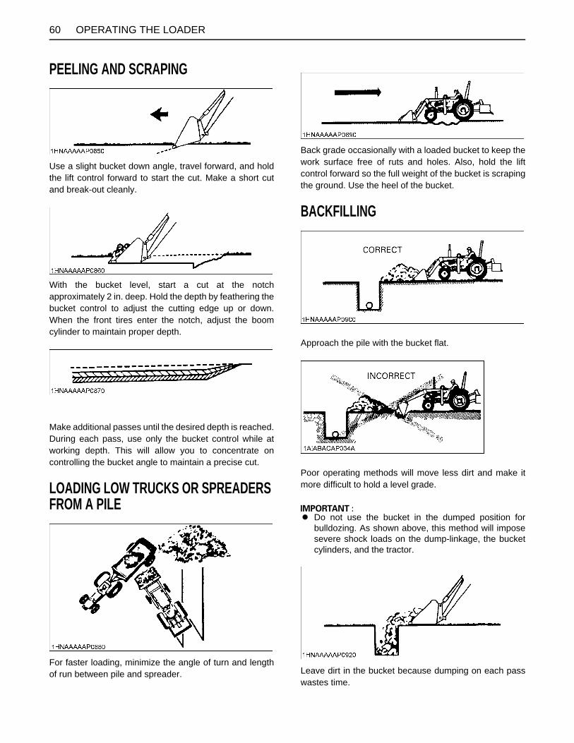
OPERATING THE LOADER60
PEELING AND SCRAPING
Use a slight bucket down angle, travel forward, and holdthe lift control forward to start the cut. Make a short cutand break-out cleanly.
With the bucket level, start a cut at the notchapproximately 2 in. deep. Hold the depth by feathering thebucket control to adjust the cutting edge up or down.When the front tires enter the notch, adjust the boomcylinder to maintain proper depth.
Make additional passes until the desired depth is reached.During each pass, use only the bucket control while atworking depth. This will allow you to concentrate oncontrolling the bucket angle to maintain a precise cut.
LOADING LOW TRUCKS OR SPREADERS FROM A PILE
For faster loading, minimize the angle of turn and lengthof run between pile and spreader.
Back grade occasionally with a loaded bucket to keep thework surface free of ruts and holes. Also, hold the liftcontrol forward so the full weight of the bucket is scrapingthe ground. Use the heel of the bucket.
BACKFILLING
Approach the pile with the bucket flat.
Poor operating methods will move less dirt and make itmore difficult to hold a level grade.
A Do not use the bucket in the dumped position forbulldozing. As shown above, this method will imposesevere shock loads on the dump-linkage, the bucketcylinders, and the tractor.
Leave dirt in the bucket because dumping on each passwastes time.

61OPERATING THE LOADER
Operate at right angles to the ditch. Taking as big a biteas the tractor can handle.
Leave dirt which drifts over the side of the bucket for finalcleanup.
Pile dirt on the high side for easier backfilling on a slope.
HANDLING LARGE HEAVY OBJECTS
To avoid serious personal injury or death:A Handling large, heavy objects can be dangerous
due to :(A) Danger of rolling the tractor over.(B) Danger of upending the tractor.(C) Danger of the object rolling or sliding down the loader boom onto the operator.A If you must perform the above work, protect
yourself by :(A) Not lifting the load higher than necessary to clear the ground when moving.(B) Adding rear ballast to the tractor to compensate for the load.(C) Not lifting large objects with equipment that does not have an anti-rollback device.(D) Moving slowly and carefully.(E) Avoiding rough terrain.(F) Keeping transport distance as short as possible and carry the load as low as possible during transport.

OPERATING THE LOADER62
VALVE LOCK
To avoid injury or death from crushing:A Do not utilize the valve lock for machine
maintenance or repair.A The valve lock is to prevent accidental
actuation when implement is not in use orduring transport.
The control valve is equipped with a valve lock feature.The control valve is locked in "NEUTRAL" position.The lock is not intended and will not prevent a leak downof the implement during the period of storage.
ATTACHING ATTACHMENTS[Option for LA240A]
A Attachments should be located on a flat, firm surfacewhen attaching and detaching them from the BX6315Quick Coupler.
1. Remove Hitch Pins and Snapper Pins from the HitchPin Bosses on the BX6315 Quick Coupler.
2. Move the loader control lever to the "dump" positionuntil the surface with the arrow marker on the BX6315Quick Coupler label gets in parallel with the ground asshown in the following illustration.
3. Move the tractor forward slowly until the arrow markeron the attachment label is close to that on the QuickCoupler label.
[When viewed from the operator's seat]
(1) Lock lever (A) "LOCK"(B) "UNLOCK"
(1) Arrow marker (A) Position this surface in parallel with the ground.(P) "PARALLEL"
(M) "MOVE FORWARD SLOWLY"
(A) Front attachment side(B) Quick Coupler side

63OPERATING THE LOADER
4. Raise the boom of the loader until the pin at the upperbosses of the attachment seat in the Quick Couplerreceivers, and the rear of the attachment is raisedslightly off the ground.
To avoid personal injury:A Do not raise attachment completely off the
ground at this point. the attachment couldswing off the quick coupler.
5. Keeping the attachment at ground level, move theloader control lever to the "roll back" position until thecylinders stop. Turn off the engine and set the parkingbrake.
6. Install both Hitch Pins and Snapper Pins as shown inthe following illustration.The illustration shows a properly attached bucket.
To avoid personal injury:A Make sure both hitch pins and snapper pins are
properly installed before moving or operatingattachments.
A Keep hitch pins and snapper pins assembled inthe BX6315 quick coupler at all times, even if noattachment is being used.
A Replace any pins or other parts which are lostor broken.
7. You are now ready to use the attached attachment.Compatible attachments can be attached anddetached using the same method.
To avoid personal injury:A Never operate or transport attachments which
are not attached completely.A Always replace damaged hardware
immediately.
(1) Pin 3 (U) "UP" position
(A) Hitch Pins(B) Snapper Pins

OPERATING THE LOADER64
DETACHING ATTACHMENTS[Option for LA240A]1. Detaching the attachments is done in the reverse of
attaching attachments.2. Lower the implement and roll it back completely. Stop
the engine and set the parking brake.3. Remove Hitch Pins and Snapper Pins.4. While sitting in the tractor operator's seat, start the
engine and slowly move the loader control lever to the"dump" position. The attachment will be pushed awayslightly from the Quick Coupler.
5. Lower the loader boom so the receivers of the QuickCoupler clear the bottom of the Upper Pins.
6. Back away from the attachment slowly.7. Reinstall Hitch Pins and Snapper Pins in the BX6315
Quick Coupler, even if no attachment is used.
DISMOUNTING THE LOADER[Option for LA240A]
To avoid machine damage or personal injury:A Remove loader from tractor only when an
approved loader bucket is attached.
Follow instructions provided in "REMOVING THELOADER" section in this operator's manual.
ATTACHMENTS[Option for LA240A]
BBucketRigid type square 48" bucket can be used as quickbuckets for BX6315 quick coupler.
BPallet fork
ASSEMBLE PALLET FORK[Option for LA240A]1. Install the fork to the middle of the frame.
(fit the lower hook of the fork to the center notch of theframe)
2. Slide the fork to the desired position.
(1) Rigid type square 48" bucket
LOADER MODEL RATED CAPACITY
LA240A 310 LBS.
(1) Fork
(1) Fork

65OPERATING THE LOADER
3. Push the lock lever and slide the fork slightly until thelock pin engages with one of the notches to lock thefolk.
4. The other fork can be installed using the sameprocedures.
(1) Lock lever

66 OPERATING THE BACKHOE
OPERATING THE BACKHOE
OPERATING SPEEDTo avoid personal injury:A Use care when operating on slopes to avoid tip
over. Travel at speed compatible with safeoperation, especially when operating in uneventerrain, crossing ditches or while turning.
1. This backhoe can be operated at any engine speedfrom about 75% of rated rpm to factory rated rpm. Thebackhoe is most efficient at rated engine speed. However, in special digging condition, for optimal fueleconomy, or in residential neighborhood where noisemay be a consideration, the engine speed can belowered to about 75% of rated rpm.
2. When operating in temperature below 0 C (32 F), runthe tractor engine below about 50% of rated rpm untilthe oil temperature exceeds 0 C (32 F).
BACKHOE CONTROLS
To avoid personal injury:A For all excavation work, operate the backhoe from
the backhoe operator's seat only.A Do not tamper with any backhoe control valve
relief pressure setting.The relief valve is preset at the factory. Changingthe setting can cause overloading of the backhoeand the tractor and serious personal injury mayresult.
The backhoe is controlled by using the 2 lever "joystick"system. The left lever controls the boom and swingcircuits, and the right lever controls the dipperstick andbucket circuits. The further the levers are moved from"NEUTRAL", the faster the component will move. Learnthe "feature" of the controls for smooth and precisecomponent movement.
BBoom & Swing LeverPushing the lever forward will lower the boom, and pullingit back will raise it.Movement of the lever to the left will swing the bucket tothe left, and right lever movement will swing to the right.By moving the lever out of the plus "+" position ; into an"X" relationship, it is possible to raise or lower and swingat the same time.
(1) Boom and swing lever(2) Dipperstick and bucket lever(3) Stabilizer control lever, left(4) Stabilizer control lever, right
(1) Boom and swing lever

67OPERATING THE BACKHOE
BDipperstick & Bucket LeverPushing the lever forward will crowd out the dipperstickand the bucket out and pulling it back will crowd them in.Lever movement to the left will curl the bucket to fill it, andright lever movement will dump the bucket.Again, movement into an "X" relationship will crowd in andfill the bucket, or crowd out and dump the bucket.With experience, the combination of both "joystick" leverswill allow lift, swing, crowd out and spoil dumping, all inone smooth movement, or lowering, swing, crowd in andbucket filling with reverse movement.
BStabilizer Control LeversThe stabilizers are the only controls that may be operatedfrom out of the backhoe operator's seat over then only forthe purpose of mounting or dismounting backhoe fromtractor.Be sure to stay well clear of stabilizers, arms and padsduring installation or removal process. This is necessarybecause the mounting step moves up and down inconjunction with the stabilizer cylinder.Moving the levers downward will lower the stabilizers, andupward lever movement will raise them.
PLACING THE STABILIZERS
To avoid personal injury:A When working on slopes, one stabilizer may be
lower than the other.A When digging on a hillside, always dump the
bucket on the uphill side of excavation.A To reduce the risk of overturn on a slope, place the
spoil to the high side of the excavation.
1. Lower the stabilizers and remove the weight of thebackhoe from the rear wheels. However, one or bothrear tires should remain in light contact with theground. This will give the backhoe the widest possiblestance and the lowest center of gravity.If the rear wheels are raised too high, digging depthwill be reduced and undue stress will be exerted on thebackhoe frame components.If the slope is unusually steep, cut a level surface withthe loader and pile the spoil on the downhill side. Backdrag and pack the spoil so it will support the stabilizeron the low side. This procedure is recommended whena wall, tree line or other obstruction prevents placingbackhoe spoil on the high side of the excavation.
2. The loader bucket should be lowered to give thebackhoe unit a "tri-pod" stance. With the loader bucketin ground contact, front tire bounce will not be a factorin overall control. When possible, the loader bucketcutting edge should be lowered vertically into theground surface. This will assist the stabilizers, notallowing the unit to shift, while excavating. However,on a slope, the bottom of the bucket should be used,and only the side that contacts the uneven terrain. Toomuch loader down pressure, on a slope, will restrictthe unit from being correctly leveled and will place anundue twist through the loader bucket and lift arms.
(1) Dipperstick and bucket lever
(1) Stabilizer control lever, left(2) Stabilizer control lever, right

OPERATING THE BACKHOE68
GENERAL BACKHOE OPERATION
To avoid personal injury:A Do not dig under the stabilizer or tractor,
especially in soft or sandy condition. Take extra precaution in wet or thawing ground.These conditions can become unstable veryquickly and may collapse under the weight of themachine and may tip over.
A Use care for buried material such as electrical,telephone, gas and water lines. When in doubt,contact local utility companies for their buriedlocation.
A Do not use the tractor to pull out tree stumps with theboom dipper extended and the bucket in its crowdedposition.
BDipperstick DiggingLower the bucket to the ground, the same as with bucketdigging, then curl until the bucket teeth are flat on theground.Using only the crowd cylinder, retract the dipperstick,dragging the bucket through the trench until it isapproximately half full. Begin to curl the bucket in whilecontinuing to crowd in, until the bucket is completely full.Raise and swing the boom and dump the bucket in thespoil area on the high side of the trench or excavation.
BSpoil Pile Location
To avoid personal injury:A Do not place spoil close to the edge of the
excavation where its weight could cause a cave-in.
Carefully preplan the location for the spoil that will beremoved from the excavation. The location will varydepending on the excavation being dug.The height of spoil pile can be controlled without movingthe tractor. Approach the pile with the backhoe bucket fulland ready to empty. Instead of dumping on top, lower thefull bucket into the top of the pile. Begin dumping andcrowding out at the same time. As the bucket opens anddumps, the bottom of the bucket will push the top of thepile off and behind its location, safely away from theexcavation.
BStraight Wall or Cemetery DiggingStrip the top soil off the ground, within the confines of thestraight hole or grave to be dug. Clean out as muchmaterial, within the same confines, as possible withnormal digging methods.Finish the far wall by crowding out while forcing the bucketdown with the boom.Curl the bucket out to keep the bottom of the bucketvertical while making the down cut.

69OPERATING THE BACKHOE
To finish the near wall, raise the boom while crowding in.The bucket will have to be curled in to keep the cuttingedge horizontal with the wall during the up cut.
When finishing straight wall, or digging graves, in sandysoil, use a platform under the rear tires and stabilizers.The platform distributes the backhoe load over a largearea and lessens the possibility of a cave-in.
BStabilizer pads (Standard)
BStabilizer pads (Option)The stabilizer pads can be reversed without the use oftools. Change the pads depending on the job.
C When operating in dirt to prevent slippage.
C When operating on street to prevent damage to workarea.
(1) Stabilizer pads
(1) Rubber shoes

OPERATING THE BACKHOE70
A Always lower stabilizers slightly when changing fromone position to another to avoid soil splash.
TRANSPORTING
To avoid personal injury:A Before transporting the machine, raise and center
the boom, close the dipperstick, curl the bucketand engage the boom and swing locks.
A Always securely fasten the tractor / loader /backhoe, with chains and chain binders, totransport vehicle. Determine and note the load height of thebackhoe, for underpass clearance, beforetransporting.
BDriving to the Job-siteWhen driving or transporting from one job-site to another,or when using the loader such as stockpiling andbackfilling, always engage the boom and swing locks.
BTrailer TransportingWhen loading or off-loading the machine on or from trailer/ truck, use strong, secure ramps long enough to providea low angle to the transport vehicle.After loading the machine, release the boom lock, lowerthe backhoe bucket to the bed of the transport vehicle,lower the loader bucket, set the parking brake of thetractor, shut the engine off and then remove the key.Check the hood for proper securement, and remove SMVsign from holder driving transport to avoid damage,reinstall after transport.Check the local codes or regulations that may apply totractor / loader / backhoe operation on public streets orhighways, before transporting or traveling. Use SMVemblem and warning flashers as required.(SMV: Slow Moving Vehicle)
(1) Boom lock pin(2) Swing lock pin

71MAINTENANCE OF THE TRACTOR
MAINTENANCE OF THE TRACTOR
SERVICE INTERVALSNo. ItemsIndication on hour meter
Since thenRef.page50 100 150 200 250 300 350 400 450 500 550 600 650 700
1 Engine oil Change every 200 Hr 87 *1
2 Engine oil filter Replace every 200 Hr 87 *1
3 Transmission oil filter
Replace every 200 Hr 88 *1
4 Transmission fluid Change every 400 Hr 89
5 Transmission strainer
Clean every 400 Hr 90
6 Front axle case oil Change every 400 Hr 90
7 Front axle pivot Adjust every 400 Hr 89
8 Engine start system
Check every 50 Hr 81
9 OPC system Check every 50 Hr 81
10 Greasing -- every 50 Hr 80
11 Wheel bolt torque Check every 50 Hr 82
12 Battery condition Check every 100 Hr 82 *7
13Air cleaner element
Clean every 100 Hr 84 *2@
Replace every 1000 Hr or 1 year
90 *3
14 Fuel filter elementCheck every 100 Hr
@Replace every 400 Hr 90 *6
15 Fan belt Adjust every 100 Hr 85
16 HST neutral spring
Adjust every 100 Hr 86 *6
17 Brake pedal Adjust every 100 Hr 86
18Radiator hose and clamp
Check every 1 year 92 *4
Replace every 4 years 94 *6
19Power steering oil line
Check every 1 year 93 *4
Replace every 4 years 94 *6
20 Fuel lineCheck every 1 year 93 *4
@Replace every 4 years 94 *6
21 Intake air lineCheck every 1 year 93 *4
@Replace every 4 years 94 *6
22Engine breather hose
Check every 1 year 94 *4
Replace every 4 years 94 *6
23 Toe-in Adjust every 200 Hr 88
24 Engine valve clearance
Adjust every 800 Hr 90 *6
25Fuel injection nozzle Injection pressure
Check every 1500 Hr 91 *6 @
26 Injection pump Check every 3000 Hr 92 *6 @
27 Cooling system Flush every 2000 Hr or 2 years
91 *5
28 Coolant Change every 2000 Hr or 2 years
91 *5

72 MAINTENANCE OF THE TRACTOR
A The jobs indicated by must be done after the first 50 hours of operation.*1 The initial 50 hours should not be a replacement cycle.*2 Air cleaner should be cleaned more often in dusty conditions than in normal conditions.*3 Every 1,000 hours or every 1 year whichever comes faster.*4 Replace if any deterioration (crack, hardening, scar, or deformation) or damage occurred.*5 Every 2,000 hours or every 2 years whichever comes faster.*6 Consult your local KUBOTA Dealer for this service.*7 When the battery is used for less than 100 hours per year, check the battery condition by reading the indicator annually.A The items listed above (@ marked) are registered as emission related critical parts by KUBOTA in the U.S.EPA nonroad
emission regulation. As the engine owner, you are responsible for the performance of the required maintenance on theengine according to the above instruction.Please see the Warranty Statement in detail.
LUBRICANTS, FUEL AND COOLANT
Note *1 Oil amount when the oil level is at the upper level of the oil level gauge. *2 The product name of KUBOTA genuine UDT fluid may be different from that in the Operator's Manual depending on countries or territories. Consult your local KUBOTA Dealer for further detail.
A To prevent serious damage to hydraulic systems, use only KUBOTA genuine fluid or its equivalent.
29 Fuel system BleedService as required
94
30 Fuse Replace 95
31 Light bulb Replace 95
No. Locations Capacities Lubricants
1 Fuel25 L
(6.6 U.S.gals.)
No. 2-D diesel fuelNo. 1-D diesel fuel if temperature is below -10 (14 )
2 Coolant(with recovery tank)
3.1 L(3.3 U.S.qts.)
Fresh clean soft water with anti-freeze
3 Engine crankcase3.1 L *1
(3.3 U.S.qts.)
Engine oil : API Service Classification CF or higher
Above 25 (77 ) SAE30, SAE10W-30 or 15W-40
0 to 25 (32 to 77 ) SAE20, SAE10W-30 or 15W-40
Below 0 (32 ) SAE10W, SAE10W-30 or 15W-40
4 Transmission case 11.6 L (3.1 U.S.gals.) KUBOTA SUPER UDT-2 fluid *2
5 Front axle case 4.7 L (5.0 U.S.qts.) KUBOTA SUPER UDT-2 fluid *2 or SAE 80 - SAE90 gear oil
6Greasing No. of greasing points Capacity Type of grease
Battery terminal 2 moderate amount Multipurpose EP2 Grease (NLGI Grade No. 2)Speed control pedal 1 until grease overflow
73MAINTENANCE OF THE TRACTOR
C Engine Oil:A Oil used in the engine should have an American Petroleum Institute (API) service classification and Proper SAE
Engine Oil according to the ambient temperatures as shown above:
C Fuel:A Cetane number of 45 is minimum. Cetane number greater than 50 is preferred, especially for temperatures below
-20 (-4 ) or elevations above 1500 m (5000 ft).A Diesel fuels specified to EN 590 or ASTM D975 are recommended.A No.2-D is a distillate fuel of lower volatility for engines in industrial and heavy mobile service. (SAE J313 JUN87)
C Transmission Oil:*KUBOTA Super UDT-2: For an enhanced ownership experience, we highly recommend Super UDT-2 to be usedinstead of standard hydraulic/transmission fluid.Super UDT-2 is a proprietary KUBOTA formulation that delivers superior performance and protection in all operatingconditions.Regular UDT is also permitted for use in this machine.
A Indicated capacities of water and oil are manufacturer's estimate.
For North American market
A Refer to the following table for the suitable API classification engine oil according to the engine type (with internalEGR, external EGR or non-EGR) and the fuel.
Fuel usedEngine oil classification (API classification)
Oil class of engines except external EGR Oil class of engines with external EGR
Ultra Low Sulfur Fuel[<0.0015% (15 ppm)]
CF, CF-4, CG-4, CH-4 or CI-4CF or CI-4(Class CF-4, CG-4 and CH-4 engine oils cannot be used on EGR type engines)
EGR: Exhaust Gas Re-circulation
A The CJ-4 engine oil is intended for DPF (Diesel Particulate Filter) type engines, and cannot be used on this tractor.
except external EGR with external EGR
Model BX25DLB ---

74 MAINTENANCE OF THE TRACTOR
C Engine Oil:A Oil used in the engine should have an American Petroleum Institute (API) service classification and Proper SAE
Engine Oil according to the ambient temperatures as shown above:A With the emission control now in effect, the CF-4 and CG-4 lubricating oils have been developed for use of a low-
sulfur fuel on on-road vehicle engines. When an off-road vehicle engine runs on a high-sulfur fuel, it is advisable toemploy the "CF or better" lubricating oil with a high Total Base Number (TBN of 10 minimum).
C Fuel:A Cetane number of 45 is minimum. Cetane number greater than 50 is preferred, especially for temperatures below
-20 or elevations above 1500 m.A If diesel fuel with sulfur content greater than 0.5% (5000 ppm) sulfur content is used, reduce the service interval for
engine oil and filter by 50%.A NEVER use diesel fuel with sulfur content greater than 0.05% (500 ppm) for EXTERNAL EGR type engine.A DO NOT use diesel fuel with sulfur content greater than 1.0% (10000 ppm).A Diesel fuels specified to EN 590 or ASTM D975 are recommended.A No.2-D is a distillate fuel of lower volatility for engines in industrial and heavy mobile service. (SAE J313 JUN87)
C Transmission Oil:The oil used to lubricate the transmission is also used as hydraulic fluid. To insure proper operation of the hydraulicsystem and to complete lubrication of the transmission, it is important that a multi-grade transmission fluid is used inthis system. We recommend the use of KUBOTA UDT or SUPER UDT fluid for optimum protection and performance.(Consult your local KUBOTA Dealer for further detail.)Do not mix different brands together.
A Indicated capacities of water and oil are manufacturer's estimate.
For other than North American market
A Refer to the following table for the suitable API classification engine oil according to the engine type (with internalEGR, external EGR or non-EGR) and the fuel (low-sulfur or high-sulfur fuel).
Fuel usedEngine oil classification (API classification)
Oil class of engines except external EGR Oil class of engines with external EGR
High Sulfur Fuel[ 0.05% (500 ppm)]
CF(If the "CF-4, CG-4, CH-4 or CI-4" lubricating oil is used with a high-sulfur fuel, change the lubricating oil at shorter intervals. (approximately half))
---
Low Sulfur Fuel[<0.05% (500 ppm)] orUltra Low Sulfur Fuel[<0.0015% (15 ppm)]
CF, CF-4, CG-4, CH-4 or CI-4CF or CI-4(Class CF-4, CG-4 and CH-4 engine oils cannot be used on EGR type engines)
EGR: Exhaust Gas Re-circulation
A The CJ-4 engine oil is intended for DPF (Diesel Particulate Filter) type engines, and cannot be used on this tractor.
except external EGR with external EGR
Model --- ---

75PERIODIC SERVICE OF THE TRACTOR
PERIODIC SERVICE OF THE TRACTOR
To avoid personal injury or death:A Do not work under any hydraulically supported
devices. They can settle, suddenly leak down,or be accidentally lowered. If necessary to workunder tractor or any machine elements forservicing or adjustment, securely support themwith stands or suitable blocking beforehand.
HOW TO OPEN THE HOOD
To avoid personal injury from contact with movingparts;A Never open the hood or engine side cover while
the engine is running.A Do not touch muffler or exhaust pipes while
they are hot; Severe burns could result.
BHoodTo open the hood, rotate the knob to release the latch andopen the hood.
BEngine Cover1. Remove the front-end loader before removing the
engine cover. (See "REMOVING THE LOADER"section.)
2. To remove front guard, remove the bolts and the nuts.
3. Loosen the screw bolt by using a long screwdriver andremove the tail pipe.To remove the engine cover, loosen the knob bolts.
(1) Knob(2) Hood
(A) "ROTATE"
(1) Bolts(2) Nuts(3) Front guard(4) Tail pipe
(1) Tail pipe(2) Screw bolt

PERIODIC SERVICE OF THE TRACTOR76
4. Close the hood halfway and fix the band to the hood.Then, hold the hood with the band, and pull forward asshown in following figure.In the above procedure, be careful not to hit the enginecover against the head lights.It is not necessary to detach the engine cover for dailycheck.
A When reinstall the engine cover, tighten the knobbolts.
A When reinstall the front guard, tighten the bolts andthe nuts by 77.4 to 90.2 N-m (7.9 to 9.2 kgf-m, 57.1 to66.5 lbf-ft)
DAILY CHECKFor your own safety and maximum service life of themachine, make a thorough daily inspection beforeoperating the machine or starting the engine.
To avoid personal injury or death:Take the following precautions when checking thetractor.A Park the machine on firm and level ground.A Set the parking brake.A Lower the implement to the ground.A All residual pressure of the hydraulic system
released.A Stop the engine and remove the key.
BWalk Around InspectionLook around and under the tractor for such items as loosebolts, trash build-up, oil or coolant leaks, broken or wornparts.
(1) Knob bolts
(1) Band
(1) Engine cover (A) "PULL"

77PERIODIC SERVICE OF THE TRACTOR
BChecking and Refueling
To avoid personal injury:A Do not smoke while refueling.A Be sure to stop the engine and remove the key
before refueling.To avoid allergic skin reaction:A Wash hands immediately after contact with
diesel fuel.
1. Turn the key switch to "ON", check the amount of fuelby fuel gauge.
2. Fill fuel tank when fuel gauge shows 1/4 or less fuel intank.
3. Use grade No.2-Diesel fuel at temperatures above-10 (14 ).Use grade No.1-Diesel fuel at temperatures below-10 (14 ).
A Do not permit dirt or trash or water to get into the fuelsystem.
A Be careful not to let the fuel tank become empty,otherwise air will enter the fuel system, necessitatingbleeding before next engine start.
A Be careful not to spill fuel during refueling. If a spillshould occur, wipe it off at once, or it may cause a fire.
A To prevent condensation (water accumulation) in thefuel tank, fill the tank before parking overnight.
BChecking Engine Oil Level
To avoid personal injury:A Be sure to stop the engine and remove the key
before checking the oil level.
1. Park the machine on a firm, flat and level surface.2. Check engine oil before starting the engine, or, after 5
minutes or more when the engine has been stopped.3. To check the oil level, draw out the dipstick, wipe it
clean, replace it, and draw it out again. Check to seethat the oil level lies between the two notches.If the level is too low, add new oil to the prescribedlevel at the oil inlet.(See "LUBRICANTS" in "MAINTENANCE OF THETRACTOR" section.)
(1) Fuel tank cap
Fuel tank capacity 25 L (6.6 U.S.gals.)
(1) Oil inlet(2) Dipstick
(A) Oil level is acceptable within this range.

PERIODIC SERVICE OF THE TRACTOR78
A When using an oil of different maker or viscosity fromthe previous one, remove all of the old oil and oil filter. Never mix two different types of oil.
A If oil level is low, do not run engine.A When using BT602 Backhoe and checking oil level,
locate the tractor/loader/backhoe on a flat and set theloader/backhoe as illustrated below.
BChecking Transmission Fluid Level1. Park the machine on a firm, flat and level surface,
lower the implement to the ground and stop theengine.
2. To check the oil level, draw out the dipstick, wipe itclean, replace it, and draw it out again. Check to seethat the oil level lies between the two notches.If the level is too low, add new oil to the prescribedlevel at the oil inlet.(See "LUBRICANTS" in "MAINTENANCE OF THETRACTOR" section.)
A If oil level is low, do not run engine.
BChecking Coolant Level
To avoid personal injury:A Be sure to stop the engine and remove the key
before checking coolant level.A Do not remove the radiator cap while coolant is
hot. When cool, slowly rotate cap to the firststop and allow sufficient time for excesspressure to escape before removing capcompletely.
1. Check to see that the coolant level is between the "H"and "L" marks of recovery tank.
2. When the coolant level drops due to evaporation, addsoft water only. In case of leakage, add antifreeze andsoft water in the specified mixing ratio up to the "H"level.(See "Flushing Cooling System and ChangingCoolant" in "EVERY 2 YEARS" in "PERIODICSERVICE OF THE TRACTOR" section.)
A If the radiator cap has to be removed, follow the above"CAUTION" and securely retighten the cap.
A Use clean, fresh soft water and anti-freeze to fill therecovery tank.
A If water should leak, consult your local KUBOTADealer.
(1) Oil inlet(2) Dipstick
(A) Oil level is acceptable within this range.
(1) Recovery tank (A) "H"(B) "L"

79PERIODIC SERVICE OF THE TRACTOR
BCleaning Panel and Radiator Screen
To avoid personal injury:A Be sure to stop the engine and remove the key
before removing the screen.A Before checking or cleaning it, wait long
enough until it cools down.
1. Check panel screen to be sure they are clean fromdebris.
2. Detach the radiator screen, and then remove all theforeign material.
A If the dust or chaff is accumulated in the batterycompartment, open the panel and clean completely.
A Panel and radiator screen must be clean from debristo prevent engine from overheating and to allow goodair intake for air cleaner.
A Be sure to reinstall the panel on the pillar completelyto prevent the invasion of dust.
A Be sure to stop the engine to avoid personal injury andto allow good air intake for air cleaner.
BChecking Brake Pedal1. Inspect the brake pedal for free travel, and smooth
operation.2. Adjust if incorrect measurement is found:
(See "Adjusting Brake Pedal" in "EVERY 100 HOURS"in "PERIODIC SERVICE OF THE TRACTOR"section.)
BChecking Gauges, Meters and Easy Checker(TM)
1. Inspect the instrument panel for broken gauge(s),meter(s) and Easy Checker(TM) lamps.
2. Replace if broken.
BChecking Head Light, Hazard Light etc.1. Inspect the lights for broken bulbs and lenses.2. Replace if broken.
BChecking Seat Belt and ROPS1. Always check condition of seat belt and ROPS
attaching hardware before operating tractor.2. Replace if damaged.
(1) Panel(2) Knob(3) Center pillar
(A) "DETACH"
(1) Radiator screen (A) "DETACH"

PERIODIC SERVICE OF THE TRACTOR80
BChecking and Cleaning of Electrical Wiring and Battery Cables
To avoid personal injury:A A loosened terminal or connector, or damaged
wire may affect the performance of electricalcomponents or cause short circuits. Leakageof electricity could result in a fire hazard, adead battery or damage to electricalcomponents.
A Replace damaged wires or connectionspromptly.
A If a fuse blows soon after replacement, DO NOTUSE A LARGER THAN RECOMMENDED FUSEOR BYPASS THE FUSE SYSTEM.
A Many wiring connections are protected bywaterproof plugs, plug and unplug theseconnections carefully and make sure they aresealed correctly after assembly.
A Accumulation of dust, chaff or spilled fueldeposits around the battery, electrical wiring,engine or exhaust system are a fire hazard. CLEAN THESE AREAS BEFORE STARTINGWORK.To avoid premature electrical malfunctions DONOT APPLY high pressure water directly tobattery, wiring, connectors, electricalcomponents or instrument panel.
Inspect the following Regularly:1. Check wiring for chafed or cracked insulation.2. Check wiring harness clamps. Replace if necessary.3. Check connectors and terminals for looseness,
contamination or overheated (discolored)connections.
4. Check instrument panel for correct operation ofswitches and gauges.
Consult your KUBOTA Dealer regarding maintenance,diagnosis and repair.
BChecking Movable PartsIf any of the movable parts, such as levers and pedals, isnot smoothly moved because of rust or sticky material, donot attempt to force it into motion.In the above case, remove the rust or the sticky material,and apply oil or grease on the relevant spot.Otherwise, the machine may get damaged.
EVERY 50 HOURSBLubricating Grease FittingsApply a small amount of multipurpose grease to thefollowing points every 50 hours:If you operated the machine in extremely wet and muddyconditions, lubricate grease fittings more often.
(1) Grease fitting (Speed control pedal)
(1) Battery terminals

81PERIODIC SERVICE OF THE TRACTOR
BChecking Engine Start System
To avoid personal injury or death:A Do not allow anyone near the tractor while
testing.A If the tractor does not pass the test, do not
operate the tractor.
C Preparation before testing.1. Sit on operator's seat.2. Set the parking brake and stop the engine.3. Shift the range gear shift lever to "NEUTRAL" position.4. Check the speed control pedal "NEUTRAL" position.5. Shift the PTO clutch lever to "OFF" position.
C Test 1: Switch for the speed control pedal1. Make sure that the range gear shift lever is set in
"NEUTRAL" position.2. Depress the speed control pedal.3. Turn the key to "START" position.4. The engine must not crank.5. If it cranks, consult your local KUBOTA Dealer for this
service.
C Test 2: Switch for the PTO clutch lever1. Make sure that the range gear shift lever is set in
"NEUTRAL" position.2. Make sure that the speed control pedal is set in
"NEUTRAL" position.3. Shift the PTO clutch lever to "ON" position.4. Turn the key to "START" position.5. The engine must not crank.6. If it cranks, consult your local KUBOTA Dealer for this
service.
BChecking OPC System
To avoid personal injury or death:A Do not allow anyone near the tractor while
testing.A If the tractor does not pass the test, do not
operate the tractor.
C Preparation before testing.1. Sit on operator's seat.2. Set the parking brake and stop the engine.3. Shift the range gear shift lever to "NEUTRAL" position.4. Check the speed control pedal "NEUTRAL" position.5. Shift the PTO clutch lever to "OFF" position.
C Test 1: Switches for the operator's seat and thespeed control pedal
1. Start the engine.2. Depress the speed control pedal.3. Stand up. (Do not get off the machine.)4. The engine must shut off after approximately 1
second.5. If it does not stop, consult your local KUBOTA Dealer
for this service.
C Test 2: Switches for the operator's seat and thePTO clutch lever.
1. Start the engine.2. Engage the PTO clutch lever.3. Stand up. (Do not get off the machine.)4. The engine must shut off after approximately 1
second.5. If it does not stop, consult your local KUBOTA Dealer
for this service.
(1) Range gear shift lever (Hi-Lo)(2) PTO clutch lever(3) Speed control pedal
(1) Range gear shift lever (Hi-Lo)(2) PTO clutch lever(3) Speed control pedal

PERIODIC SERVICE OF THE TRACTOR82
BChecking Wheel Bolt Torque
To avoid personal injury:A Never operate tractor with a loose rim, wheel,
or axle.A Any time bolts are loosened, retighten to
specified torque.A Check all bolts frequently and keep them tight.
Check wheel bolts regularly especially when new. If theyare loose, tighten them as follows.
EVERY 100 HOURSBBattery
To avoid the possibility of battery explosion:For the refillable type battery, follow theinstructions below.A Do not use or charge the refillable type battery
if the fluid level is below the LOWER (lower limitlevel) mark. Otherwise, the battery componentparts may prematurely deteriorate, which mayshorten the battery's service life or cause anexplosion. Check the fluid level regularly andadd distilled water as required so that the fluidlevel is between the UPPER and LOWER levels.
To avoid personal injury or death:A Never remove the battery cap while the engine
is running.A Keep electrolyte away from eyes, hands and
clothes. If you are spattered with it, wash itaway completely with water immediately andget medical attention.
A Keep open sparks and flames away from thebattery at all times. Hydrogen gas mixed withoxygen becomes very explosive.
A Wear eye protection and rubber gloves whenworking around battery.
A Mishandling the battery shortens the service life andadds to maintenance costs.The original battery is maintenance free, but needssome servicing.If the battery is weak, the engine will be difficult to startand the lights will be dim. It is important to check thebattery periodically.
A When exchanging an old battery for a new one, usebattery of equal specification in table below.
(1) 149.2 to 179.0 N-m (15.2 to 18.3 kgf-m, 110 to 132 lbf-ft)
(1) 108.5 to 130.2 N-m (11.1 to 13.3 kgf-m, 80 to 96 lbf-ft)
The factory-installed battery is of non-refillable type.If the battery is weak, charge the battery or replace it with new one.
Battery Type
Volts (V)
Reserve Capacity
(min)
Cold Cranking
Amps
Normal Charging Rate(A)
526RMF 12 80 540 6.5
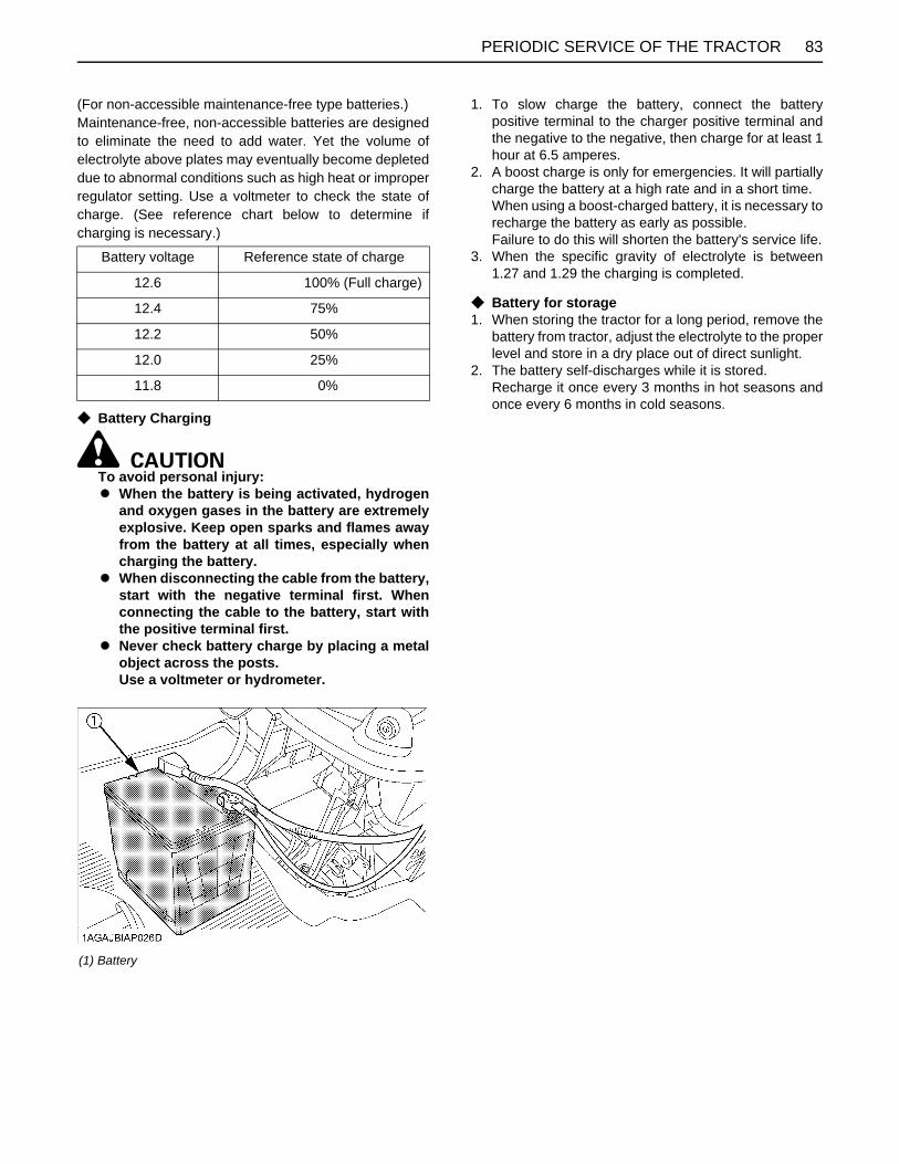
83PERIODIC SERVICE OF THE TRACTOR
(For non-accessible maintenance-free type batteries.)Maintenance-free, non-accessible batteries are designedto eliminate the need to add water. Yet the volume ofelectrolyte above plates may eventually become depleteddue to abnormal conditions such as high heat or improperregulator setting. Use a voltmeter to check the state ofcharge. (See reference chart below to determine ifcharging is necessary.)
C Battery Charging
To avoid personal injury:A When the battery is being activated, hydrogen
and oxygen gases in the battery are extremelyexplosive. Keep open sparks and flames awayfrom the battery at all times, especially whencharging the battery.
A When disconnecting the cable from the battery,start with the negative terminal first. Whenconnecting the cable to the battery, start withthe positive terminal first.
A Never check battery charge by placing a metalobject across the posts.Use a voltmeter or hydrometer.
1. To slow charge the battery, connect the batterypositive terminal to the charger positive terminal andthe negative to the negative, then charge for at least 1hour at 6.5 amperes.
2. A boost charge is only for emergencies. It will partiallycharge the battery at a high rate and in a short time.When using a boost-charged battery, it is necessary torecharge the battery as early as possible.Failure to do this will shorten the battery's service life.
3. When the specific gravity of electrolyte is between1.27 and 1.29 the charging is completed.
C Battery for storage1. When storing the tractor for a long period, remove the
battery from tractor, adjust the electrolyte to the properlevel and store in a dry place out of direct sunlight.
2. The battery self-discharges while it is stored.Recharge it once every 3 months in hot seasons andonce every 6 months in cold seasons.
Battery voltage Reference state of charge
12.6 100% (Full charge)
12.4 75%
12.2 50%
12.0 25%
11.8 0%
(1) Battery

PERIODIC SERVICE OF THE TRACTOR84
BCleaning Air Cleaner Element
To avoid personal injury:A Be sure to stop the engine and remove the key
before cleaning air cleaner element.
1. Remove the air cleaner cover and the element.(1) Undo the hook(2) Turn the cover clockwise and detach it.
2. Clean the element:1) When dry dust adheres to the element, blow
compressed air from the inside, turning theelement. Pressure of compressed air must beunder 205kPa (2.1kgf/ , 30psi).
2) When carbon or oil adheres to the element,soak the element in detergent for 15 minutesthen wash it several times in water, rinse withclean water and dry it naturally. After elementis fully dried, inspect inside of the element witha light and check if it is damaged or not.(referring to the instructions on the labelattached to the case.)
3. Replace air cleaner element:Every 1000 hours or every 1 year whichever comesfirst.
A Check to see if the evacuator valve is blocked withdust.
A The air cleaner uses a dry element, never apply oil.A Do not run the engine with filter element removed.A Align the arrow marks when reinstalling the cover. If
the cover is improperly fitted, dust passes by the baffleand directly adheres to the element.
C Evacuator ValveOpen the evacuator valve once a week under ordinaryconditions - or daily when used in a dusty place - to get ridof large particles of dust and dirt.
BChecking Fuel Filter
To avoid personal injury:A Stop the engine and remove the key before
checking fuel lines and fuel filter.A Check the fuel lines periodically. The fuel lines
are subject to wear and aging. Fuel may leakout onto the running engine, causing a fire.
1. The fuel line is made of rubber and ages regardless ofservice period.
2. After inspection, if the fuel line and clamps are founddamaged or deteriorated, replace them.
3. Check fuel filter, if it is clogged by debris orcontaminated by water, replace it.
A When the fuel line is disconnected for maintenance orrepair, plug both ends of the fuel line with a clean plugof suitable size to prevent dust and dirt from entering.Particular care must be taken in order to avoid dustand dirt getting into the fuel system. Entrance of dustand dirt causes malfunction of the fuel pump.
(1) Element(2) Cover(3) Evacuator valve
(1) Pipe clamps(2) Fuel line(3) Fuel filter
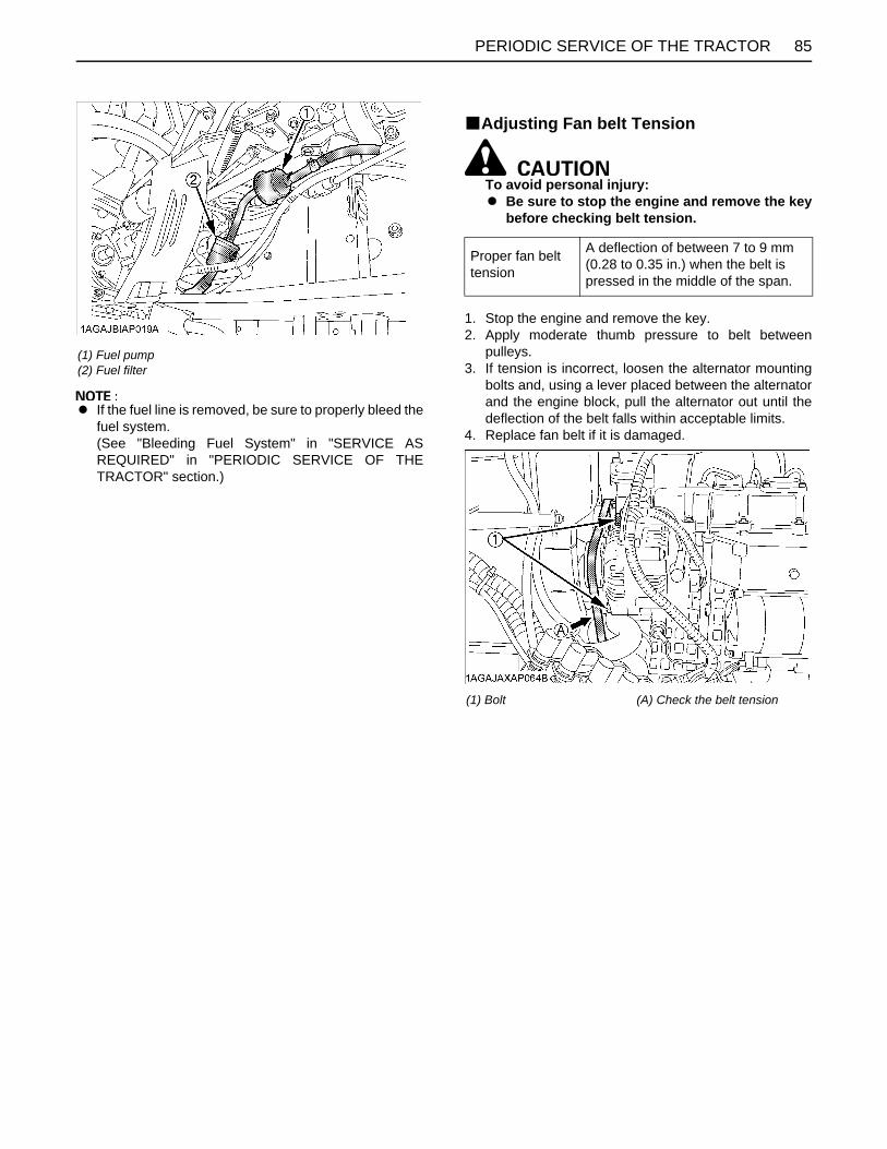
85PERIODIC SERVICE OF THE TRACTOR
A If the fuel line is removed, be sure to properly bleed thefuel system.(See "Bleeding Fuel System" in "SERVICE ASREQUIRED" in "PERIODIC SERVICE OF THETRACTOR" section.)
BAdjusting Fan belt Tension
To avoid personal injury:A Be sure to stop the engine and remove the key
before checking belt tension.
1. Stop the engine and remove the key.2. Apply moderate thumb pressure to belt between
pulleys.3. If tension is incorrect, loosen the alternator mounting
bolts and, using a lever placed between the alternatorand the engine block, pull the alternator out until thedeflection of the belt falls within acceptable limits.
4. Replace fan belt if it is damaged.
(1) Fuel pump(2) Fuel filter
Proper fan belt tension
A deflection of between 7 to 9 mm (0.28 to 0.35 in.) when the belt is pressed in the middle of the span.
(1) Bolt (A) Check the belt tension
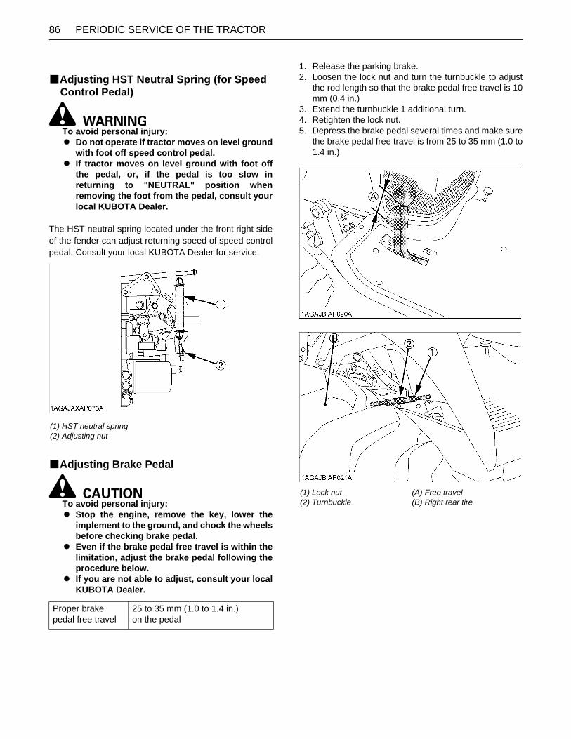
PERIODIC SERVICE OF THE TRACTOR86
BAdjusting HST Neutral Spring (for Speed Control Pedal)
To avoid personal injury:A Do not operate if tractor moves on level ground
with foot off speed control pedal.A If tractor moves on level ground with foot off
the pedal, or, if the pedal is too slow inreturning to "NEUTRAL" position whenremoving the foot from the pedal, consult yourlocal KUBOTA Dealer.
The HST neutral spring located under the front right sideof the fender can adjust returning speed of speed controlpedal. Consult your local KUBOTA Dealer for service.
BAdjusting Brake Pedal
To avoid personal injury:A Stop the engine, remove the key, lower the
implement to the ground, and chock the wheelsbefore checking brake pedal.
A Even if the brake pedal free travel is within thelimitation, adjust the brake pedal following theprocedure below.
A If you are not able to adjust, consult your localKUBOTA Dealer.
1. Release the parking brake.2. Loosen the lock nut and turn the turnbuckle to adjust
the rod length so that the brake pedal free travel is 10mm (0.4 in.)
3. Extend the turnbuckle 1 additional turn.4. Retighten the lock nut.5. Depress the brake pedal several times and make sure
the brake pedal free travel is from 25 to 35 mm (1.0 to1.4 in.)
(1) HST neutral spring(2) Adjusting nut
Proper brake pedal free travel
25 to 35 mm (1.0 to 1.4 in.) on the pedal
(1) Lock nut(2) Turnbuckle
(A) Free travel(B) Right rear tire

87PERIODIC SERVICE OF THE TRACTOR
EVERY 200 HOURSBReplacing Engine Oil Filter
To avoid personal injury:A Be sure to stop the engine and remove the key
before changing the oil filter cartridge.A Allow engine to cool down sufficiently, oil can
be hot and can burn.
1. Remove the oil filter.2. Put a film of clean engine oil on the rubber seal of the
new filter.3. Tighten the filter quickly until it contacts the mounting
surface.Tighten filter by hand an additional 1/2 turn only.
4. After the new filter has been replaced, the engine oilnormally decreases a little. Make sure that the engineoil does not leak through the seal and be sure to checkthe oil level on the dipstick. Then, replenish the engineoil up to the prescribed level.
5. Properly dispose of used oil.
A To prevent serious damage to the engine, use only aKUBOTA genuine filter.
BChanging Engine Oil
To avoid personal injury:A Be sure to stop the engine and remove the key
before changing the oil.A Allow engine to cool down sufficiently, oil can
be hot and can burn.
1. To drain the used oil, remove the drain plug at thebottom of the engine and drain the oil completely intothe oil pan.
2. After draining reinstall the drain plug.3. Fill with the new oil up to the upper notch on the
dipstick.(See "LUBRICANTS" in "MAINTENANCE OF THETRACTOR" section.)
4. Properly dispose of used oil.
(1) Engine oil filter
Oil capacity with filter 3.1 L (3.3 U.S.qts.)
(1) Oil inlet(2) Dipstick
(A) Oil level is acceptable within this range
(1) Drain plug

PERIODIC SERVICE OF THE TRACTOR88
BReplacing Transmission Oil Filter
To avoid personal injury:A Be sure to stop the engine before changing the
oil filter cartridge.A Allow engine to cool down sufficiently, oil can
be hot and can burn.
1. Remove the oil filter.2. Put a film of clean transmission oil on rubber seal of
new filter.3. Tighten the filter quickly until it contacts the mounting
surface.Tighten filter by hand an additional 1/2 turn only.
4. After the new filter has been replaced, thetransmission fluid level will decrease a little. Make surethat the transmission fluid does not leak through theseal, and check the fluid level.Top up if necessary.
5. Properly dispose of used oil.
A To prevent serious damage to the hydraulic system,use only a KUBOTA genuine filter.
BAdjusting Toe-in1. Park tractor on a firm, flat and level place.2. Turn steering wheel so that front wheels are in the
straight ahead position.3. Lower the implement to the ground, lock the parking
brake, stop the engine and remove the key.4. Measure distance between tire beads at front of tire,
hub height.5. Measure distance between tire beads at rear of tire,
hub height.6. Front distance should be 0 to 5 mm (0 to 0.2 in.) less
than rear distance. If not, adjust tie rod length.
C Adjusting procedure1. Loosen the lock nut and turn the tie rod to adjust the
rod length until the proper toe-in measurement isobtained.
2. Retighten the lock nut.
(1) Filter
(A) Wheel - to - wheel distance at rear(B) Wheel - to - wheel distance at front(C) "FRONT"
(1) Lock nuts(2) Tie rod

89PERIODIC SERVICE OF THE TRACTOR
EVERY 400 HOURSBAdjusting Front Axle PivotIf the front axle pivot pin adjustment is not correct, frontwheel vibration can occur causing vibration in the steeringwheel.
C Adjusting procedureRemove the split pin, tighten the adjusting nut (tighteningtorque 20 N-m, 2.0 kgf-m, 15 lbf-ft), then make sure thatone of the nut slots aligns with the split pin hole, tightenthe nut slightly if necessary to align. Replace the split pin.
BChanging Transmission Fluid
To avoid personal injury:A Allow engine to cool down sufficiently, oil can
be hot and can burn.
1. To drain the used oil, remove the drain plug at thebottom of the transmission case and drain the oilcompletely into the oil pan.
2. After draining reinstall the drain plug.3. Clean the transmission strainer.4. Fill with new KUBOTA SUPER UDT fluid up to the
upper notch on the dipstick.(See "LUBRICANTS" in "MAINTENANCE OF THETRACTOR" section and "DAILY CHECK" in"PERIODIC SERVICE OF THE TRACTOR" section.)
5. After running the engine for a few minutes, stop it andcheck the oil level again, add oil to prescribed level.
6. Properly dispose of used oil.
A Do not operate the tractor immediately after changingthe transmission fluid.Run the engine at medium speed for a few minutes toprevent damage to the transmission.
(1) Adjusting nut(2) Split pin
Oil capacity 11.6 L (3.1 U.S. gals.)
(1) Drain plug
(1) Oil inlet(2) Dipstick
(A) Oil level is acceptable within this range.

PERIODIC SERVICE OF THE TRACTOR90
BCleaning Transmission StrainerWhen changing the transmission fluid, disassemble andrinse the strainer with nonflammable solvent to completelyclean off filings.When reassembling be careful not to damage the parts.
A Since the fine filings in the oil can damage theprecision component parts of the hydraulic system, theend of the suction line is provided with an oil strainer.
BChanging Front Axle Case Oil1. Park the machine on a firm, flat and level surface.2. To drain the used oil, remove the right and left drain
plugs and oil gauge at the front axle case and drainthe oil completely into the oil pan.
3. After draining reinstall the drain plugs.4. Remove the right and left breather plugs.5. Fill with new oil up to the upper notch on the dipstick.
(See "LUBRICANTS" in "MAINTENANCE OF THETRACTOR" section.)
A After 10 minutes, check the oil level again; add oil toprescribed level.
6. After filling, reinstall the oil gauge and breather plugs.
BReplacing Fuel Filter ElementConsult your local KUBOTA Dealer for this service.
EVERY 800 HOURSBAdjusting Engine Valve ClearanceConsult your local KUBOTA Dealer for this service.
EVERY 1000 HOURS OR 1 YEARBReplacing Air Cleaner ElementReplace every 1000 hours or every 1 year whichevercomes faster.(See "Cleaning Air Cleaner Element" in "EVERY 100HOURS" in "PERIODIC SERVICE" section.)
(1) Strainer(2) Filter plate
Oil capacity 4.7 L (5.0 U.S.qts.)
(1) Breather plug(2) Oil gauge with dipstick(3) Drain plug
(A) Oil level is acceptable within this range

91PERIODIC SERVICE OF THE TRACTOR
EVERY 1500 HOURSBChecking Fuel Injection Nozzle Injection
PressureConsult your local KUBOTA Dealer for this service.
EVERY 2000 HOURS OR 2 YEARSBe sure to do the following service once every 2000 hoursor every 2 years whichever comes faster.
BFlushing Cooling System and Changing Coolant
To avoid personal injury or death:A Do not remove radiator cap while coolant is
hot. When cool, slowly rotate cap to the firststop and allow sufficient time for excesspressure to escape before removing the capcompletely.
1. Stop the engine and let cool down.2. To drain the coolant, open the radiator drain plug and
remove radiator cap. The radiator cap must beremoved to completely drain the coolant.
3. After all coolant is drained, close the drain plug.4. Fill with clean soft water and cooling system cleaner.5. Follow directions of the cleaner instruction.6. After flushing, fill with clean soft water and anti-freeze
until the coolant level is just below the radiator cap.Install the radiator cap securely.
7. Fill with coolant up to the "H" mark on the recoverytank.
8. Start and operate the engine for few minutes.9. Stop the engine and let cool.10.Check coolant level of recovery tank and add coolant
if necessary.
A Do not start engine without coolant.A Use clean, fresh soft water and anti-freeze to fill the
radiator and recovery tank.A When mixing the anti-freeze with water, the anti-freeze
mixing ratio is 50%.A Securely tighten radiator cap. If the cap is loose or
improperly fitted, water may leak out and the enginecould overheat.
BAnti-Freeze
To avoid personal injury or death:A When using antifreeze, put on some protection
such as rubber gloves (Antifreeze containspoison.).
A If should drink antifreeze, throw up at once andtake medical attention.
A When antifreeze comes in contact with the skinor clothing, wash it off immediately.
A Do not mix different types of Antifreeze.The mixture can produce chemical reactioncausing harmful substances.
A Antifreeze is extremely flammable andexplosive under certain conditions. Keep fireand children away from antifreeze.
A When draining fluids from the engine, placesome container underneath the engine body.
A Do not pour waste onto the grounds, down adrain, or into any water source.
A Also, observe the relevant environmentalprotection regulations when disposing ofantifreeze.
If it freezes, coolant can damage the cylinders andradiator. If the ambient temperature falls below 0(32 ) or before a long-term storage, let out cooling watercompletely, or mix fresh water with long-life coolant and fillthe radiator and recovery tank with the mixture.
Coolant capacity(With recovery tank)
3.1 L (3.3 U.S. qts.)
(1) Radiator cap
(1) Drain plug

PERIODIC SERVICE OF THE TRACTOR92
1. Long-life coolant (hereafter LLC) comes in severaltypes. Use ethylene glycol (EG) type for this engine.
2. Before employing LLC-mixed cooling water, fill theradiator with fresh water and empty it again.Repeat this procedure 2 or 3 times to clean up theinside.
3. Mixing the LLCPut the LLC in cooling water in the percentage (%) fora target temperature. When mixing, stir it up well, andthen fill into the radiator.
4. The procedure for the mixing of water and antifreezediffers according to the make of the antifreeze and theambient temperature. Refer to SAE J1034 standard,more specifically also to SAE J814c.
A When mixing the antifreeze with water, the anti-freezemixing ratio is 50%.
D At 1.013 x 10 Pa (760mmHg) pressure (atmospheric).A higher boiling point is obtained by using a radiatorpressure cap which permits the development ofpressure within the cooling system.
5. Adding the LLC(1) Add only water if the mixture reduces in amount
by evaporation.(2) If there is a mixture leak, add the LLC of the same
manufacturer and type in the same mixturepercentage.D Never add any long-life coolant of different
manufacturer. (Different brands may havedifferent additive components, and the enginemay fail to perform as specified.)
6. When the LLC is mixed, do not employ any radiatorcleaning agent. The LLC contains anticorrosive agent.If mixed with the cleaning agent, sludge may build up,adversely affecting the engine parts.
7. Kubota's genuine long-life coolant has a service life of2 years. Be sure to change the coolant every 2000hours or 2 years whichever comes faster.
A The above data represent industry standards thatnecessitate a minimum glycol content in theconcentrated antifreeze.
A When the coolant level drops due to evaporation, addwater only to keep the antifreeze mixing ratio less than50%. In case of leakage, add antifreeze and water inthe specified mixing ratio before filling in to theradiator.
A Anti-freeze absorbs moisture. Keep unused anti-freeze in a tightly sealed container.
A Do not use radiator cleaning agents when anti-freezehas been added to the coolant. (Anti-freeze containsan anti-corrosive agent, which will react with theradiator cleaning agent forming sludge which willaffect the engine parts.)
EVERY 3000 HOURSBChecking Injection PumpConsult your local KUBOTA Dealer for this service.
EVERY 1 YEARBChecking Radiator Hoses and Clamps
To avoid personal injury:A Be sure to stop the engine and remove the key
before checking radiator hose and clamp.
1. If hose clamps are loose or water leaks, tighten bandssecurely.
2. Replace hoses and tighten hose clamps securely, ifradiator hoses are swollen, hardened or cracked.
3. Properly dispose of used coolant.Replace hoses and hose clamps if you checked andfound that hoses are swollen, hardened or cracked.
C Precaution at OverheatingTake the following actions in the event the coolanttemperature be nearly or more than the boiling point, whatis called "Overheating".1. Stop the machine operation in a safe place and keep
the engine idling unloaded.2. Don't stop the engine suddenly, but stop it after about
5 minutes of unloaded idling.3. Keep yourself well away from the machine for an
additional 10 minutes or until the steam has blown out.
Vol %Anti-freeze
Freezing Point Boiling Point*
4050
-24-37
-12-34
106108
222226
(1) Radiator hoses (2 pcs)(2) Hose clamps (4 pcs)
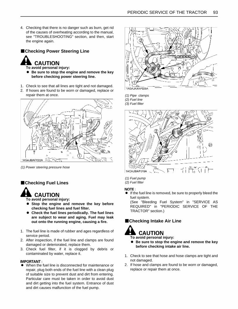
93PERIODIC SERVICE OF THE TRACTOR
4. Checking that there is no danger such as burn, get ridof the causes of overheating according to the manual,see "TROUBLESHOOTING" section, and then, startthe engine again.
BChecking Power Steering Line
To avoid personal injury:A Be sure to stop the engine and remove the key
before checking power steering line.
1. Check to see that all lines are tight and not damaged.2. If hoses are found to be worn or damaged, replace or
repair them at once.
BChecking Fuel Lines
To avoid personal injury:A Stop the engine and remove the key before
checking fuel lines and fuel filter.A Check the fuel lines periodically. The fuel lines
are subject to wear and aging. Fuel may leakout onto the running engine, causing a fire.
1. The fuel line is made of rubber and ages regardless ofservice period.
2. After inspection, if the fuel line and clamps are founddamaged or deteriorated, replace them.
3. Check fuel filter, if it is clogged by debris orcontaminated by water, replace it.
A When the fuel line is disconnected for maintenance orrepair, plug both ends of the fuel line with a clean plugof suitable size to prevent dust and dirt from entering.Particular care must be taken in order to avoid dustand dirt getting into the fuel system. Entrance of dustand dirt causes malfunction of the fuel pump.
A If the fuel line is removed, be sure to properly bleed thefuel system.(See "Bleeding Fuel System" in "SERVICE ASREQUIRED" in "PERIODIC SERVICE OF THETRACTOR" section.)
BChecking Intake Air Line
To avoid personal injury:A Be sure to stop the engine and remove the key
before checking intake air line.
1. Check to see that hose and hose clamps are tight andnot damaged.
2. If hose and clamps are found to be worn or damaged,replace or repair them at once.
(1) Power steering pressure hose
(1) Pipe clamps(2) Fuel line(3) Fuel filter
(1) Fuel pump(2) Fuel filter

PERIODIC SERVICE OF THE TRACTOR94
BChecking Engine Breather HoseConsult your local KUBOTA Dealer for this service.
EVERY 4 YEARSBReplacing Radiator Hose (Water pipes)Replace the hoses and clamp bands every 4 years orearlier if you checked and found that hoses are swollen,hardened or cracked. Consult your local KUBOTA Dealerfor this service.)
BReplacing Power Steering HoseConsult your local KUBOTA Dealer for this service.
BReplacing Fuel LinesConsult your local KUBOTA Dealer for this service.
BReplacing Engine Breather HoseConsult your local KUBOTA Dealer for this service.
BReplacing Intake Air LineConsult your local KUBOTA Dealer for this service.
SERVICE AS REQUIREDBBleeding Fuel SystemAir must be removed:1. When the fuel filter or lines are removed.2. When the tank is completely empty.3. After the tractor has not been used for a long period of
time.
C Bleeding procedure is as follows:1. Fill the fuel tank with fuel.
2. Turn the key switch to "ON" position for about 30seconds. Doing so allows fuel pump to work and pumpair out of the fuel system.
3. Start the engine and run for about 30 seconds, andthen stop the engine.
(1) Hose(2) Hose clamp
(1) Fuel pump(2) Fuel filter

95PERIODIC SERVICE OF THE TRACTOR
BReplacing Fuse
The tractor electrical system is protected from potentialdamage by fuses.A blown fuse indicates that there is an overload or shortsomewhere in the electrical system.If any of the fuses should blow, replace with a new one ofthe same capacity.
A Before replacing a blown fuse, determine why the fuseblew and make any necessary repairs. Failure tofollow this procedure may result in serious damage tothe tractor electrical system. Refer to thetroubleshooting section of this manual or your localKUBOTA Dealer for specific information dealing withelectrical problems.
C Protected circuit[Fuse box]
BReplacing Light Bulb1. Head light
Take the bulb out of the light body and replace with anew one.
2. Other lightsDetach the lens and replace the bulb.
(1) Fuse box
(1) Slow blow fuse
FUSE No. CAPACITY (A) Protected circuit
(1) 15 SOLENOID
(2) 15 HAZARD
(3) 15 ACC
(4) 20 WORKING LIGHT
(5) 10 DC OUTLET
(6) 10 TIMER RELAY
CAPACITY (A) Protected circuit
Slow blow Fuse (50A)Check circuit againstwrong battery connection
Light Capacity
Head light 37.5W
Tail light 12.8W
Hazard light 23W

96 MAINTENANCE OF THE LOADER
MAINTENANCE OF THE LOADER
To avoid personal injury:A Be sure to check and service the tractor on a
flat surface with the bucket on the ground,engine shut off, the key removed and theparking brake on.
LUBRICATION1. Lubricate all grease fittings every 10 hours of
operation. Also, lubricate joints of control lever linkageevery 10 hours. High quality grease designating"extreme pressure" and containing Molybdenumdisulfide is recommended. This grease may specify"Moly EP" on its label.
2. Daily before operation, check the tractor hydraulic fluidlevel. If low, add as described in "PERIODICSERVICE OF THE TRACTOR" section. Also changethe filter element and the hydraulic fluid asrecommended in "PERIODIC SERVICE OF THETRACTOR" section.
RE-TIGHTENING OF HARDWAREAfter 20 to 30 hours of initial loader operation, re-tightenall mounting bolts and nuts to the required torque value asspecified in the "Tightening Torque Chart".
BTightening Bolts and NutsTighten all bolts and nuts with required torque.
A Before finally tightening all mounting hardware, startthe engine and apply down pressure to the bucket untilthe loader raises the front wheels slightly, and makesure that the mounting pins can be rotated easily.Tighten all bolts and nuts in this position.
Location Bolt / Nut Required Torque
Main frameM14
bolts or nuts
147 N-m(15.0 kgf-m)(108 lbf-ft)

97MAINTENANCE OF THE LOADER
DAILY CHECKS1. Check all hardware daily before operation.
Tighten hardware to torque values as specified in the"Tightening Torque Chart".
2. With the engine off and the bucket on the ground,inspect all hoses for cuts or wear. Check for signs ofleaks and make sure all fittings are tight.
To avoid serious personal injury:A Escaping hydraulic fluid under pressure can
have sufficient force to penetrate skin, causingserious personal injury. Before disconnectinglines, be sure to relieve all pressure.Before applying pressure to system, be sure allconnections are tight and that lines, tubes, andhoses are not damaged.Fluid escaping from a very small hole can bealmost invisible. Use a piece of cardboard orwood, rather than hands, to search forsuspected leaks.
If injured by escaping fluid, see a doctor atonce. Serious infection or allergic reaction willdevelop if proper medical treatment is notadministered immediately.
A When removing the engine side covers, becareful not to touch hot loader cylinders.Allow all surfaces to cool before performingmaintenance.
EVERY 50 HOURSBChecking main frame bolt and nut torque
To avoid serious injury:A Never operate front loader with a loose main
frame.A Any time bolts and nuts are loosened, retighten
to specified torque.A Check all bolts and nuts frequently and keep
them tight.
Check main frame bolts and nuts regularly especiallywhen new. If they are loose, tighten them as follows.
(1) Hydraulic line(2) Cardboard(3) Magnifying glass
(1) Tightening torque : 147 N-m (15.0 kgf-m, 108 lbf-ft)

98 MAINTENANCE OF THE BACKHOE
MAINTENANCE OF THE BACKHOE
DAILY CHECKSTo avoid personal injury:A Never make any repairs, service or
adjustments when the hydraulic system isunder pressure, when the engine is running orwhen any backhoe cylinder is under load.
A Escaping hydraulic fluid under pressure canhave sufficient force to penetrate skin, causingserious personal injury. Before disconnectinglines, be sure to relieve all pressure. Beforeapplying pressure to system, be sure allconnections are tight and that lines, pipes andhoses are not damaged.Fluid escaping from a very small hole can bealmost invisible. Do not use hands to searchfor suspected leak, use a piece of cardboard orwood. If injured by escaping fluid, see a doctorat once. Serious infection or allergic reactionwill develop if proper medical treatment is notadministered immediately.
1. The backhoe is run by the tractor hydraulic system.Daily before operation, check the tractor hydrauliclevel. If low, replenish the oil as described in"PERIODIC SERVICE OF THE TRACTOR" section.Also check the filter screen and change the hydraulicfluid as recommended in "PERIODIC SERVICE OFTHE TRACTOR" section.
2. Check all hardware before daily operation. Tightenhardware to torque values as specified in the "Generaltorque specification".
3. With the engine off and the bucket on the ground,inspect all hoses for cuts or wear. Check for signs ofleaks and make sure all fittings are tight.
4. For safe operation, check that the mounting pin slidebar is inserted into the hole of the main frame beforeoperation.
(1) Hydraulic line(2) Cardboard(3) Magnifying glass
(1) Oil port(2) Dipstick
(1) Mounting pin(2) Slide bar

99MAINTENANCE OF THE BACKHOE
LUBRICATIONLubricate all grease fittings every 10 hours of operation.High quality grease designated "extreme pressure" andcontaining Molybdenum disulfide is recommended. Thisgrease may specify "Moly Ep" on its label.
BUCKET SERVICE
To avoid personal injury:A When servicing or repairing pins in cylinder
ends, bucket, etc., always use a brass drift andhammer. Failure to do so could result in injuryfrom flying metal fragments.
BChanging the Backhoe BucketChanging the backhoe bucket becomes necessary as thetype of job to be accomplished changes. In most backhoeoperations, this is a common occurrence.By using the following instructions, this job will be quickand easy. Always select a smooth level area to changebuckets.Place the bucket to be installed on its bottom, near thebackhoe dipperstick and the bucket to be removed.Position the bucket to be removed, hydraulically, into this"NATURAL" position, just touching the ground.
BChanging the Bucket TeethThe bucket teeth are locked with bolts on the bucket. Eventhough the teeth are heat-treated and hard, they willeventually need replacement. As the teeth become worn,the resistance of digging will increase. When the teeth areworn, install new teeth using new bolts.Bucket teeth may be removed and stored when drainagework is required. This type of work may not requiretrenching teeth.
(1) Bucket(2) Bucket teeth(3) Bolt

MAINTENANCE OF THE BACKHOE100
BGeneral torque specification
American standard cap screws with UNC or UNF threads
Metric cap screws
SAE grade No. GR5 or GR8 Property class8.8
Approx. SAE GR5
(lbf-ft)1/4 (N-m)
(kgf-m)
7.2 to 8.6 9.8 to 11.7
1.0 to 1.2
(lbf-ft)M6 (N-m)
(kgf-m)
7.2 to 8.3 9.8 to 11.2
1.0 to 1.1
(lbf-ft)5/16 (N-m)
(kgf-m)
14 to 17 19 to 23.1
1.9 to 2.4
(lbf-ft)M8 (N-m)
(kgf-m)
17.4 to 20.223.6 to 27.4
2.4 to 2.8
(lbf-ft)3/8 (N-m)
(kgf-m)
25 to 3033.9 to 40.7
3.5 to 4.2
(lbf-ft)M10 (N-m)
(kgf-m)
35.5 to 41.248.1 to 55.8
4.9 to 5.7
(lbf-ft)1/2 (N-m)
(kgf-m)
65 to 78 88.1 to 105.8
9.0 to 10.8
(lbf-ft)M12 (N-m)
(kgf-m)
57.2 to 66.577.5 to 90.1
7.9 to 9.2
(lbf-ft)9/16 (N-m)
(kgf-m)
90 to 108 122 to 146.4
12.4 to 14.9
(lbf-ft)M14 (N-m)
(kgf-m)
91.2 to 108 124 to 14712.6 to 15.0
(lbf-ft)5/8 (N-m)
(kgf-m)
130 to 156176.3 to 211.5
18.0 to 21.6
(lbf-ft)M16 (N-m)
(kgf-m)
145 to 166196 to 225
20.0 to 23.0
Top of bolt
Length

101STORAGE OF THE TRACTOR
STORAGE OF THE TRACTOR
To avoid personal injury or death:A Do not clean the machine while the engine is
running.A To avoid the danger of exhaust fume
poisoning, do not operate the engine in aclosed building without proper ventilation.
A When storing, remove the key from the keyswitch to avoid unauthorized persons fromoperating the tractor and getting injured.
TRACTOR STORAGEIf you intend to store your tractor for an extended periodof time, follow the procedures outlined below. Theseprocedures will insure that the tractor is ready to operatewith minimum preparation when it is removed fromstorage.1. Check the bolts and nuts for looseness, and tighten if
necessary.2. Apply grease to tractor areas where bare metal will
rust also to pivot areas.3. Detach the weights from the tractor body.4. Inflate the tires to a pressure a little higher than usual.5. Change the engine oil and run the engine to circulate
oil throughout the engine block and internal movingparts for about 5 minutes.
6. With all implements lowered to the ground, coat anyexposed hydraulic cylinder piston rods with grease.
7. Remove the battery from the tractor. Store the batteryfollowing the battery storage procedures.(See "Battery" in "EVERY 100 HOURS" in "PERIODICSERVICE OF THE TRACTOR" section.)
8. Keep the tractor in a dry place where the tractor issheltered from the elements. Cover the tractor.
9. Store the tractor indoors in a dry area that is protectedfrom sunlight and excessive heat. If the tractor must bestored outdoors, cover it with a waterproof tarpaulin.Jack the tractor up and place blocks under the frontand rear axles so that all 4 tires are off the ground.Keep the tires out of direct sunlight and extreme heat.
A When washing the tractor, be sure to stop the engine.Allow sufficient time for the engine to cool beforewashing.
A Cover the tractor after the muffler and the engine havecooled down.
REMOVING THE TRACTOR FROM STORAGE1. Check the tire air pressure and inflate the tires if they
are low.2. Jack the tractor up and remove the support blocks
from under the front and rear axles.3. Install the battery. Before installing the battery, be sure
it is fully charged.4. Check the fan belt tension.5. Check all fluid levels (engine oil, transmission/
hydraulic oil, engine coolant and any attachedimplements).
6. Start the engine. Observe all gauges. If all gauges arefunctioning properly and reading normal, move thetractor outside. Once outside, park the tractor and letthe engine idle for at least 5 minutes. Shut the engineoff and walk around tractor and make a visualinspection looking for evidence of oil or water leaks.
7. With the engine fully warmed up, release the parkingbrake and test the brakes for proper adjustment as youmove forward. Adjust the brakes as necessary.

102 REMOVING THE LOADER
REMOVING THE LOADER
To avoid personal injury:A Make sure an approved bucket is attached
before removing the loader from the tractor.A For removing the loader, choose flat and hard
ground, preferably concrete.A If the ground surface is soft, place suitable
planks on the ground for the bucket and stand.A When starting the engine or using the loader
control lever, always sit in the operator's seat.A Make sure the bucket and stand are at ground
level.
1. Raise the boom until the stand can be rotated.2. Stop the engine.3. Remove the spring pin holding the stand to the boom.4. Slide the stand leftward and rotate it until the hole in
the stand and pin on the boom are aligned.Then slide the stand rightward and insert the spring pinas shown.
5. Start the engine and run at idle.6. Dump the bucket approximately 20 degrees.7. Lower the boom and raise the front wheels slightly.
A Lift the front wheels with the bucket. Do not attempt tolift them with the stand.
8. Stop the engine.9. Remove the mounting pins from the loader side frame
and retain them in the plate of side frame.
(1) Stand(2) Spring pin
(1) Stand
(1) Mounting pin
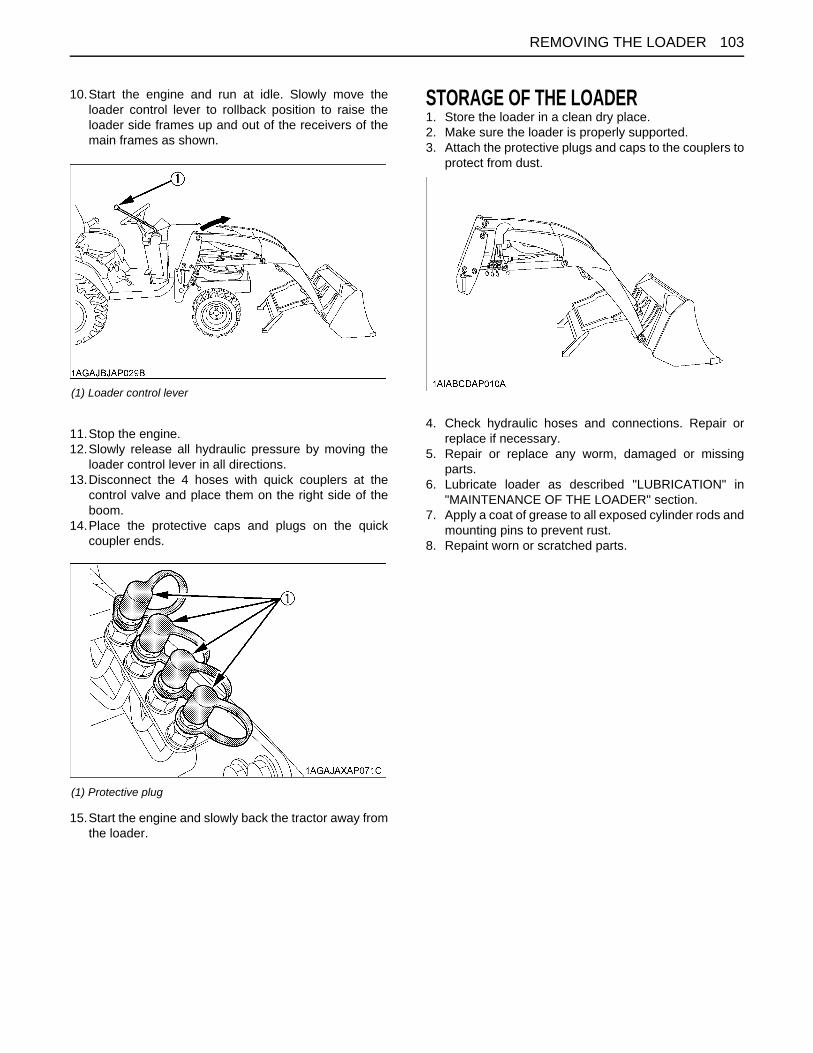
103REMOVING THE LOADER
10.Start the engine and run at idle. Slowly move theloader control lever to rollback position to raise theloader side frames up and out of the receivers of themain frames as shown.
11.Stop the engine.12.Slowly release all hydraulic pressure by moving the
loader control lever in all directions.13.Disconnect the 4 hoses with quick couplers at the
control valve and place them on the right side of theboom.
14.Place the protective caps and plugs on the quickcoupler ends.
15.Start the engine and slowly back the tractor away fromthe loader.
STORAGE OF THE LOADER1. Store the loader in a clean dry place.2. Make sure the loader is properly supported.3. Attach the protective plugs and caps to the couplers to
protect from dust.
4. Check hydraulic hoses and connections. Repair orreplace if necessary.
5. Repair or replace any worm, damaged or missingparts.
6. Lubricate loader as described "LUBRICATION" in"MAINTENANCE OF THE LOADER" section.
7. Apply a coat of grease to all exposed cylinder rods andmounting pins to prevent rust.
8. Repaint worn or scratched parts.
(1) Loader control lever
(1) Protective plug
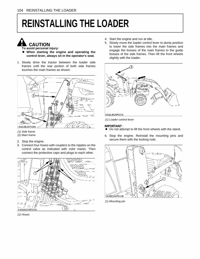
104 REINSTALLING THE LOADER
REINSTALLING THE LOADER
To avoid personal injury:A When starting the engine and operating the
control lever, always sit in the operator's seat.
1. Slowly drive the tractor between the loader sideframes until the rear portion of both side framestouches the main frames as shown.
2. Stop the engine.3. Connect four hoses with couplers to the nipples on the
control valve as indicated with color marks. Thenconnect the protective caps and plugs to each other.
4. Start the engine and run at idle.5. Slowly move the loader control lever to dump position
to lower the side frames into the main frames andengage the bosses of the main frames to the guidebosses of the side frames. Then lift the front wheelsslightly with the loader.
A Do not attempt to lift the front wheels with the stand.
6. Stop the engine. Reinstall the mounting pins andsecure them with the locking rods.
(1) Side frame(2) Main frame
(1) Hoses
(1) Loader control lever
(1) Mounting pin

105REINSTALLING THE LOADER
7. Start the engine.8. Raise the boom until the stand can be rotated.9. Stop the engine.10.Store the stand to their original positions and secure it
with the spring pin as shown.
11.Start the engine.12.Lower the boom and level the bucket.
(1) Stand (2) Spring pin

106 REMOVING THE BACKHOE
REMOVING THE BACKHOE
REMOVAL OF THE BACKHOETo avoid personal injury:A Before starting the engine, always sit in the
tractor operator's seat.A Before getting off the tractor, make sure that
PTO lever is off and range gear shift lever is inneutral. Then set the parking brake.
A Keep hands, feet and body from betweentractor and backhoe. Never allow any part ofbody under the machine.
A Before leaving the backhoe operator's seat,fully lower the boom to the ground.
A Before removing the backhoe, set the swinglock pin.
A Before removing the backhoe, set the engine speedlow idle.
A For removing the backhoe, locate the tractor / loader /backhoe on a flat level and hard surface, preferablyconcrete.If the surface is soft, place a board on the ground forthe bucket and stabilizers.
1. Set the swing lock pin to prevent the pivoting of theboom before removing the backhoe.
2. Stand beside the rear tire, fully close the dipperstick,curl the bucket and lower the boom until the back ofbucket contacts the ground.
3. Keep the stabilizer pads at about 381 mm (15.0 in.)high.
4. Raise the rear wheels slightly with the boom andremove the mounting pins.
5. Put the mounting pins in the holes on the step of thebackhoe.
(1) Swing lock pin
(A) 381 mm (15.0 in.)
(1) Mounting pin
(1) Mounting pins
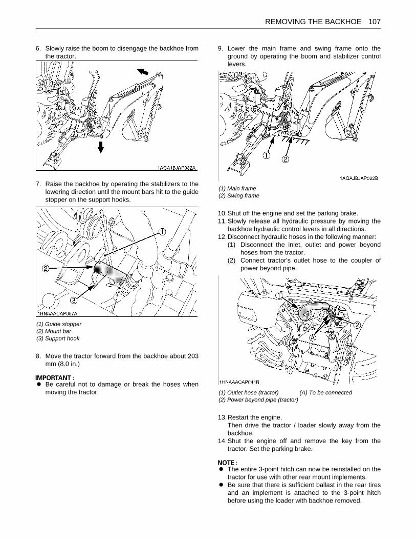
107REMOVING THE BACKHOE
6. Slowly raise the boom to disengage the backhoe fromthe tractor.
7. Raise the backhoe by operating the stabilizers to thelowering direction until the mount bars hit to the guidestopper on the support hooks.
8. Move the tractor forward from the backhoe about 203mm (8.0 in.)
A Be careful not to damage or break the hoses whenmoving the tractor.
9. Lower the main frame and swing frame onto theground by operating the boom and stabilizer controllevers.
10.Shut off the engine and set the parking brake.11.Slowly release all hydraulic pressure by moving the
backhoe hydraulic control levers in all directions.12.Disconnect hydraulic hoses in the following manner:
(1) Disconnect the inlet, outlet and power beyondhoses from the tractor.
(2) Connect tractor's outlet hose to the coupler ofpower beyond pipe.
13.Restart the engine.Then drive the tractor / loader slowly away from thebackhoe.
14.Shut the engine off and remove the key from thetractor. Set the parking brake.
A The entire 3-point hitch can now be reinstalled on thetractor for use with other rear mount implements.
A Be sure that there is sufficient ballast in the rear tiresand an implement is attached to the 3-point hitchbefore using the loader with backhoe removed.
(1) Guide stopper(2) Mount bar(3) Support hook
(1) Main frame(2) Swing frame
(1) Outlet hose (tractor)(2) Power beyond pipe (tractor)
(A) To be connected

REMOVING THE BACKHOE108
STORAGE OF THE BACKHOE1. Store the backhoe in a dry place.2. Apply a coat of grease to all exposed cylinder rods to
prevent rusting.3. If the backhoe is being stored outside, cover the
backhoe with suitable weather cover. This will keepmoisture, dirt and other airborne debris from gettinginto the system.
4. Repair or replace any worn, damaged or missingparts.
A When storing the backhoe, install the dust caps ontothe backhoe's hydraulic nipples to preventcontamination.

109REINSTALLING THE BACKHOE
REINSTALLING THE BACKHOE
To avoid personal injury or death:A When starting the engine, always sit in the
operator's seat.A When getting off the tractor, make sure that
PTO lever is "OFF" and range gear shift lever isin "NEUTRAL". Set the parking brake.
A Keep hands, feet and body from betweentractor and backhoe. Never allow any part ofbody under the machine.
To avoid personal injury:A Make sure the tractor PTO is disengaged.
A Before reinstalling the backhoe, set the engine speedto low idle.
1. Remove the 3-point hitch and / or drawbar. (ifequipped)
2. Detach the mower, if attached in position.3. Make sure the swing lock pin is installed.4. Slowly back the tractor / loader, centering to the
backhoe main frame.Stop the tractor 254 to 304 mm (10.0 to 12.0 in.) awayfrom the backhoe.
5. Shut the engine off and set the parking brake.6. Connect the inlet, outlet and power beyond hoses of
the backhoe to the outlet hose, power beyond pipeand return pipe of the tractor.
A Make sure both hoses are firmly connected beforestarting the engine.
7. Restart the engine.
To avoid personal injury or death:A Do not move the joystick control lever to the
swing position.
8. Stand beside the rear tire. Move the boom to fullyraising position and raise the backhoe by operating thestabilizers until the mount bar on the backhoe mainframe is slightly higher than the tractor main framesupport hooks.
A If the support hooks are not parallel to the mount bars,adjust with the stabilizers.
(1) Inlet hose (Backhoe)(2) Outlet hose (Backhoe)(3) Power beyond hose (Backhoe)(4) Outlet hose (Tractor)(5) Return pipe (Tractor)(6) Power beyond pipe (Tractor)
(1) Mount bar(2) Support hook

REINSTALLING THE BACKHOE110
9. Move the tractor backward until the support hooks onthe tractor main frame are just beneath the mount barson the backhoe main frame.
10.Lower the mount bars onto the support hooks byoperating the stabilizer and boom control levers.
11.Move the boom slowly to the lowering position, andengage the guide plates of the main frame to thebosses of sub frame. Then raise the rear wheelsslightly by operating the boom to the loweringdirection.
To avoid serious injury or death:A Make sure pins are in all the way slide bar
secured and backhoe securely attached.
12.Shut off the engine. Reinstall the mounting pins, andinsert the slide bars of the mounting pins to the lowerhole of the main frame.
A If the slide bar of the mounting pins is inserted to theupper hole, the mounting pin comes off and thebackhoe might come off. Therefore, please make sureto insert the slide bar to the lower hole.
A Move the tractor / loader / backhoe to an open areaand cycle all backhoe functions. This will check theiroperation and flow oil back through the system,filtering it and refilling each circuit. Check the hydraulicoil level before putting the backhoe into full operation.See "MAINTENANCE OF THE TRACTOR" section foroil type and correct level.
(1) Guide stop(2) Mount bar(3) Support hook
(1) Mounting pin(2) Slide bar

111TROUBLESHOOTING
TROUBLESHOOTING
ENGINE TROUBLESHOOTINGIf something is wrong with the engine, refer to the table below for the cause and its corrective measure.If you have any questions, consult your local KUBOTA Dealer.
Trouble Cause Countermeasure
Engine is difficult to start or won't start.
A No fuel flow. A Check the fuel tank and the fuel filter.Replace filter if necessary.
A Air or water is in the fuel system. A Check to see if the fuel line coupler bolt andnut are tight.
A Bleed the fuel system.(See "Bleeding Fuel System" in "SERVICE ASREQUIRED" in "PERIODIC SERVICE OFTHE TRACTOR" section.)
A Remove water from the system and replacethe fuel filter.
A In winter, oil viscosity increases,and engine revolution is slow.
A Use oils of different viscosities, depending onambient temperatures.
A Use engine block heater. (Option)
A Battery becomes weak and theengine does not turn over quickenough.
A Clean battery cables and terminals.A Charge the battery.A In cold weather, always remove the battery
from the engine, charge and store it indoors.Install it on the tractor only when the tractor isgoing to be used.
Insufficient engine power.A Insufficient or dirty fuel.A The air cleaner is clogged.
A Check the fuel system.A Clean or replace the element.
Engine stops suddenly.A Insufficient fuel. A Refuel.
A Bleed the fuel system if necessary.
Exhaust fumes are colored.
BlackA Fuel quality is poor.A Too much oil.A The air cleaner is clogged.
A Change the fuel and fuel filter.A Check the proper amount of oil.A Clean or replace the element.
Bluewhite
A The inside of exhaust muffler isdamp from fuel.
A Injection nozzle trouble.A Fuel quality is poor.
A Heat the muffler by applying load to theengine.
A Check the injection nozzle.A Change the fuel and fuel filter.
Engine overheats.
A Engine overloaded. A Shift to lower gear or reduce load.
A Low coolant level. A Fill cooling system to the correct level;check radiator and hoses for looseconnections or leaks.
A Loose or defective fan belt. A Adjust or replace fan belt.
A Dirty radiator core or grille screens. A Remove all trash.
A Coolant flow route corroded. A Flush cooling system.

112 OPTIONS
OPTIONS
Consult your local KUBOTA Dealer for further details.A 18 x 8.5-10 Turf TireA 26 x 12.0-12 Turf TireA Engine Block heaterFor facilitating starting and reducing warm up period in cold weather.
A Rear Work Light For high visibility for night work
A Rear wheel weightA Sunshade for ROPSA Tool box

113APPENDICES
APPENDICES
INDEX12V Electric Outlet............................................383-point Hitch Lowering Speed ..........................48Air Cleaner Element .........................................84Air Cleaner Element .........................................90Anti-Freeze.......................................................91Attaching and detaching implements ...............46Battery ..............................................................82Block Heater (Option).......................................25Boom & Swing Lever........................................66Brake Pedal......................................................31Brake Pedal......................................................79Brake Pedal......................................................86Bucket ..............................................................64Check Chains ...................................................46Cold Weather Starting ......................................25Coolant Level ...................................................78Coolant Temperature Gauge............................36Cutting Height Control Dial...............................51Differential Lock................................................38Dimensions.......................................................10Dipperstick & Bucket Lever ..............................67Dipperstick Digging ..........................................68Directions for Use of Power Steering ...............39Do not Operate the Tractor at Full Speed for theFirst 50 Hours. ..............................................27Driving to the Job-site.......................................70Dual Tires .........................................................53Easy Checker(TM) ...........................................36Electrical Wiring and Battery Cables ................80Engine Breather Hose ......................................94Engine Breather Hose ......................................94Engine Cover....................................................75Engine Oil.........................................................87Engine Oil Filter................................................87Engine Oil Level ...............................................77Engine Start System.........................................81Engine Valve Clearance...................................90Fan belt Tension...............................................85Flushing Cooling System and Coolant .............91Foldable ROPS ................................................29Front Axle Case Oil ..........................................90Front Axle Pivot ................................................89Front Ballast .....................................................55Front Wheel Drive Lever ..................................33
Front Wheels ................................................... 53Fuel Filter......................................................... 84Fuel Filter Element .......................................... 90Fuel Gauge...................................................... 36Fuel Injection Nozzle Injection Pressure ......... 91Fuel Lines ........................................................ 93Fuel Lines ........................................................ 94Fuel System..................................................... 94Fuse................................................................. 95Gauges, Meters and Easy Checker(TM) ......... 79General torque specification.......................... 100Glove Box ........................................................ 38Hand Throttle Lever ......................................... 33Hazard Light Switch......................................... 31Head Light Switch............................................ 31Head Light, Hazard Light etc. .......................... 79Hood ................................................................ 75Hourmeter/Tachometer ................................... 37HST Neutral Spring (for Speed Control Pedal) 86Hydraulic Control ............................................. 48Hydraulic Control Unit Use Reference Chart ... 52Hydraulic Outlet ............................................... 49Immediately Stop the Engine if: ....................... 35Inflation Pressure............................................. 53Injection Pump................................................. 92Installing the 3-Point Hitch............................... 47Intake Air Line.................................................. 93Intake Air Line.................................................. 94Lift Capacity (Per SAE J31) ............................. 13Lifting Rod (Right)............................................ 46Light Bulb......................................................... 95Liquid Ballast in Rear Tires.............................. 20Lubricating Grease Fittings.............................. 80Lubricating Oil for New Tractors ...................... 27Main frame bolt and nut torque........................ 97Movable Parts.................................................. 80OPC System.................................................... 81Operating on a Slopes and Rough Terrain ...... 39Operating the Tractor on a Road..................... 39Operator's Seat................................................ 30Pallet fork......................................................... 64Panel and Radiator Screen ............................. 79Parking ............................................................ 37Parking Brake Pedal ........................................ 33Power Steering Hose....................................... 94

APPENDICES114
Power Steering Line .........................................93PTO Clutch Lever.............................................43PTO Drive Shaft ...............................................44PTO Select Lever .............................................42PTO Shaft Cover and Shaft Cap......................43Radiator Hose (Water pipes)............................94Radiator Hoses and Clamps ............................92Range Gear Shift Lever (Hi-Lo)........................32Rear Ballast......................................................55Rear Wheels.....................................................54Refueling ..........................................................77Removing the 3-Point Hitch..............................47Seat Belt...........................................................31Seat Belt and ROPS.........................................79Specifications ...................................................11Speed Control Pedal ........................................34Speed Set Device.............................................34Spoil Pile Location............................................68Stabilizer Control Levers ..................................67Stabilizer pads (Option)....................................69Stabilizer pads (Standard)................................69Stationary PTO.................................................43Stopping ...........................................................35Straight Wall or Cemetery Digging ...................68The Backhoe Bucket ........................................99The Bucket Teeth .............................................99Tightening Bolts and Nuts ................................96To Fold the ROPS............................................27To Raise the ROPS to Upright Position ...........28Toe-in ...............................................................88Top Link............................................................46Trailer Transporting ..........................................70Transmission Fluid ...........................................89Transmission Fluid Level..................................78Transmission Oil Filter......................................88Transmission Strainer ......................................90Transport the Tractor Safely.............................39Turn Signal Light Switch...................................31Walk Around Inspection ...................................76Warm-up and Transmission Oil in the Low
Temperature Range .....................................26Wheel Bolt Torque............................................82

KUBOTA Corporation is ...Since its inception in 1890, KUBOTA Corporation has grown to rankas one of the major firms in Japan.
To achieve this status, the company has through the yearsdiversified the range of its products and services to a remarkableextent. Nineteen plants and 16,000 employees produce over 1,000different items, large and small.
All these products and all the services which accompany them,however, are unified by one central commitment. KUBOTAmakes products which, taken on a national scale, are basicnecessities. Products which are indispensable. Products whichare intended to help individuals and nations fulfill the potentialinherent in their environment. KUBOTA is the Basic NecessitiesGiant.
This potential includes water supply, food from the soil and from thesea, industrial development, architecture and construction, andtransportation.
Thousands of people depend on KUBOTA’s know-how, technology,experience and customer service. You too can depend onKUBOTA.