operator’s manual pump ps,...
TRANSCRIPT

5000184964 05 1111
5 0 0 0 1 8 4 9 6 4
Operator’s Manual
Pump
PS, 3-Phase
EN

Copyright notice © Copyright 2011 by Wacker Neuson Production Americas LLCAll rights, including copying and distribution rights, are reserved.This publication may be photocopied by the original purchaser of the machine. Any other type of reproduction is prohibited without express written permission from Wacker Neuson Production Americas LLC.Any type of reproduction or distribution not authorized by Wacker Neuson Production Americas LLC represents an infringement of valid copyrights. Violators will be prosecuted.
Trademarks All trademarks referenced in this manual are the property of their respective owners.
Manufacturer Wacker Neuson Production Americas LLCN92W15000 Anthony AvenueMenomonee Falls, WI 53051 U.S.A.Tel: (262) 255-0500 · Fax: (262) 255-0550 · Tel: (800) 770-0957www.wackerneuson.com
Original instructions This Operator’s Manual presents the original instructions. The original language of this Operator’s Manual is American English.

PS 3-Phase Series Foreword
ForewordSAVE THESE INSTRUCTIONS—This manual contains important instructions for the machine models below. These instructions have been written expressly by Wacker Neuson Production Americas LLC and must be followed during installation, operation, and maintenance of the machines.
Machines included in this manual:
Machine documentation
From this point forward in this documentation, Wacker Neuson Production Americas LLC will be referred to as Wacker Neuson.Keep a copy of the Operator’s Manual with the machine at all times. Use the separate Parts Book supplied with the machine to order replacement parts. Refer to the separate Repair Manual for detailed instructions on servicing and repairing the machine.If you are missing any of these documents, please contact Wacker Neuson to order a replacement or visit www.wackerneuson.com. When ordering parts or requesting service information, be prepared to provide the machine model number, item number, revision number, and serial number.
Expectations for information in this manual
This manual provides information and procedures to safely operate and maintain the above Wacker Neuson model(s). For your own safety and to reduce the risk of injury, carefully read, understand, and observe all instructions described in this manual. Wacker Neuson expressly reserves the right to make technical modifications, even without notice, which improve the performance or safety standards of its machines.The information contained in this manual is based on machines manufactured up until the time of publication. Wacker Neuson reserves the right to change any portion of this information without notice.
Model Part NumberPS2 1503 0009186, 0008801–0008806PS3 1503 0009187, 0009188, 0008807–0008812PS2 2203 0009189, 0009190, 0008813–0008818PS3 2203 0009191, 0009192, 0008819–0008824PS2 3703 0009193, 0009194, 0008825–0008830PS3 3703 0009195, 0009196, 0008831–0008836PS4 3703 0009197, 0009198, 0008837–0008842PS3 5503 0009199, 0009200, 0008843–0008848PS4 5503 0009201, 0009202, 0008849–0008854PS4 7503HH 0009203, 0009204, 0008855–0008860PS4 7503HF 0009205, 0009206, 0008861–0008866PS4 11103HH 0009207, 0009208, 0008867–0008870, 0008876, 0008877PS4 11103HF 0009209, 0009210, 0008871–0008874, 0008878, 0008879
wc_tx001370gb.fm3

Foreword PS 3-Phase Series
Manufacturer’s approvalThis manual contains references to approved parts, attachments, and modifications. The following definitions apply:
Approved parts or attachments are those either manufactured or provided by Wacker Neuson. Approved modifications are those performed by an authorized Wacker Neuson service center according to written instructions published by Wacker Neuson.Unapproved parts, attachments, and modifications are those that do not meet the approved criteria.
Unapproved parts, attachments, or modifications may have the following consequences:
Serious injury hazards to the operator and persons in the work areaPermanent damage to the machine which will not be covered under warranty
Contact your Wacker Neuson dealer immediately if you have questions about approved or unapproved parts, attachments, or modifications.
wc_tx001370gb.fm4
Original Declaration of Conformity
2011
-CE
-PS
3 P
hase
_en.
fm
EC Declaration of Conformity
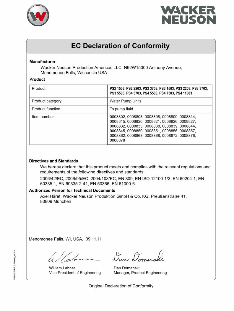
ManufacturerWacker Neuson Production Americas LLC, N92W15000 Anthony Avenue, Menomonee Falls, Wisconsin USA
Product
Product
Product category
Product function
Item number
PS2 1503, PS2 2203, PS2 3703, PS3 1503, PS3 2203, PS3 3703, PS3 5503, PS4 3703, PS4 5503, PS4 7503, PS4 11003
Water Pump Units
To pump fluid
0008802, 0008803, 0008808, 0008809, 0008814, 0008815, 0008820, 0008821, 0008826, 0008827, 0008832, 0008833, 0008838, 0008839, 0008844, 0008845, 0008850, 0008851, 0008856, 0008857, 0008862, 0008863, 0008868, 0008872, 0008876, 0008878
Directives and StandardsWe hereby declare that this product meets and complies with the relevant regulations and requirements of the following directives and standards:2006/42/EC, 2006/95/EC, 2004/108/EC, EN 809, EN ISO 12100-1/2, EN 60204-1, EN 60335-1, EN 60335-2-41, EN 50366, EN 61000-6.
Authorized Person for Technical DocumentsAxel Häret, Wacker Neuson Produktion GmbH & Co. KG, Preußenstraße 41, 80809 München
Menomonee Falls, WI, USA, 09.11.11
William LahnerVice President of Engineering
Dan DomanskiManager, Product Engineering


Table of ContentsPS 3-Phase Series
Foreword 3
EC Declaration of Conformity 5
1 Safety Information 9
1.1 Signal Words Used in this Manual ....................................................... 91.2 Machine Description and Intended Use ............................................... 91.3 Service Safety .................................................................................... 121.4 Labels ................................................................................................. 13
2 Lifting and Transporting 15
3 Installation 16
3.1 Components ....................................................................................... 163.2 Preparing the Machine for First Use ................................................... 173.3 Application Area ................................................................................. 173.4 Preparing for installation ..................................................................... 183.5 Checks to Make Before Installation .................................................... 193.6 Electrical Wiring .................................................................................. 21
4 Operation 24
4.1 Before Operation ................................................................................ 244.2 Trial Operation .................................................................................... 254.3 Operating current ............................................................................... 254.4 Operating voltage ............................................................................... 264.5 Vibration ............................................................................................ 264.6 Operation ............................................................................................ 264.7 Motor Protector ................................................................................... 274.8 Emergency Shutdown Procedure ....................................................... 28
wc_bo5000184964_05TOC.fm 7

Table of Contents PS 3-Phase Series
5 Maintenance 295.1 Periodic Maintenance Schedule ..........................................................295.2 Maintenance and Inspection ...............................................................305.3 Storage ................................................................................................305.4 Lubricant Inspection and Changing Procedures .................................315.5 Replacement Parts ..............................................................................325.6 Disassembly and Reassembly ............................................................335.7 Graphic (1.5 kW, 2.2 kW, 3.7 kW, 5.5 kW) ..........................................345.8 Graphic Components ..........................................................................355.9 Disassembly Procedure for 1.5 kW, 2.2 kW, 3.7 kW and
5.5 kW Models ....................................................................................355.10 Graphic (7.5 kW, 11 kW) .....................................................................375.11 Graphic Components ..........................................................................385.12 Disassembly Procedure for 7.5 kW and 11 kW ...................................395.13 Troubleshooting ...................................................................................41
6 Technical Data 43
6.1 Standard Specifications .......................................................................436.2 Operating Specifications .....................................................................44
7 AEM Safety Manual 49
8 wc_bo5000184964_05TOC.fm

PS 3-Phase Series Safety Information
1 Safety Information1.1 Signal Words Used in this ManualThis manual contains DANGER, WARNING, CAUTION, NOTICE, and NOTE signal words which must be followed to reduce the possibility of personal injury, damage to the equipment, or improper service.
NOTICE: Used without the safety alert symbol, NOTICE indicates a situa-tion which, if not avoided, could result in property damage.
Note: A Note contains additional information important to a procedure.
1.2 Machine Description and Intended UseThis machine is a submersible water pump. The Wacker Neuson Submersible Pump consists of an electric motor, an impeller, a strainer, and a metal casing with ports for water suction and discharge. Power is supplied to the pump through a corded plug or a hard-wired connection, depending on the installation. The operator connects hoses to the pump and routes them so that water is pumped from the work area and discharged into an appropriate location.
This is the safety alert symbol. It is used to alert you to potential personal hazards.Obey all safety messages that follow this symbol.
DANGERDANGER indicates a hazardous situation which, if not avoided, will result in death or serious injury.
To avoid death or serious injury from this type of hazard, obey all safety messages that follow this signal word.
WARNINGWARNING indicates a hazardous situation which, if not avoided, could result in death or serious injury.
To avoid possible death or serious injury from this type of hazard, obey all safety mes-sages that follow this signal word.
CAUTION! CAUTION indicates a hazardous situation which, if not avoided, could result in minor or moderate injury.
To avoid possible minor or moderate injury from this type of hazard, obey all safety mes-sages that follow this signal word.
wc_si000041gb.fm 9

Safety Information PS 3-Phase Series
This machine is intended to be used for general de-watering applications. This machine is intended for the pumping of clear water, or water containing solids up to the size stated within the products specifications, and up to the flow, head, and suction lift limits also stated within the product specifications.This machine has been designed and built strictly for the intended use described above. Using the machine for any other purpose could permanently damage the machine or seriously injure the operator or other persons in the area. Machine damage caused by misuse is not covered under warranty. The following are some examples of misuse:• Pumping flammable, explosive, or corrosive fluids• Pumping hot or volatile fluids that result in pump cavitation• Operating the pump outside of product specifications due to
incorrect diameter hoses, incorrect length hoses, other inlet or outlet restrictions, or excessive suction lift or head
• Using the machine as a ladder, support, or work surface• Using the machine to carry or transport passengers or equipment• Operating the machine outside of factory specifications• Operating the machine in a manner inconsistent with all warnings
found on the machine and in the Operator’s Manual.
This machine has been designed and built in accordance with the latest global safety standards. It has been carefully engineered to eliminate hazards as far as practicable and to increase operator safety through protective guards and labeling. However, some risks may remain even after protective measures have been taken. They are called residual risks. On this machine, they may include exposure to:• Electric shock from improper electrical connections or high
voltage• Personal injury from improper lifting techniques• Projectile hazard from dischargeTo protect yourself and others, make sure you thoroughly read and understand the safety information presented in this manual before operating the machine.Operating and Electrical Safety
To reduce risk of electric shock, connect only to a properly grounded,grounding-type receptacle.Risk of electric shock—this pump has not been investigated for use inswimming pool areas.An acceptable motor-control switch shall be provided at the time ofinstallation according to local codes and regulations.
WARNING
10 wc_si000041gb.fm

PS 3-Phase Series Safety Information
To reduce risk of electric shock, follow instructions in this manual forproper installation.CAUTION: This pump may automatically restart. Prior to working onthe pump or control panel, all supply circuits must be disconnected.CAUTION: Risk of shock—do not remove cord and strain relief.Operator qualificationsOnly trained personnel are permitted to start, operate, and shut down the machine. They also must meet the following qualifications:• have received instruction on how to properly use the machine• are familiar with required safety devicesThe machine must not be accessed or operated by:• children• people impaired by alcohol or drugs
Personal Protective Equipment (PPE)Wear the following Personal Protective Equipment (PPE) while operating this machine:• Close-fitting work clothes that do not hinder movement• Safety glasses with side shields• Hearing protection• Safety-toed footwear
wc_si000041gb.fm 11

Safety Information PS 3-Phase Series
1.3 Service SafetyService trainingBefore servicing or maintaining the machine:• Read and understand the instructions contained in all manuals
delivered with the machine.• Familiarize yourself with the location and proper use of all
controls and safety devices. • Only trained personnel shall troubleshoot or repair problems
occurring with the machine.• Contact Wacker Neuson for additional training if necessary.When servicing or maintaining this machine:• Do not allow improperly trained people to service or maintain the
machine. Personnel servicing or maintaining the machine must be familiar with the associated potential risks and hazards.
Personal Protective Equipment (PPE)Wear the following Personal Protective Equipment (PPE) while servicing or maintaining this machine:• Close-fitting work clothes that do not hinder movement• Safety glasses with side shields• Hearing protection• Safety-toed footwearIn addition, before servicing or maintaining the machine:• Tie back long hair.• Remove all jewelry (including rings).
Replacing parts and labels• Replace worn or damaged components.• Replace all missing and hard-to-read labels.• When replacing electrical components, use components that are
identical in rating and performance as the original components.• When replacement parts are required for this machine, use only
Wacker Neuson replacement parts or those parts equivalent to the original in all types of specifications, such as physical dimensions, type, strength, and material.
12 wc_si000041gb.fm

PS 3-Phase Series Safety Information
1.4 LabelsA nameplate listing the model number, item number, revi-sion number, and serial number is attached to each unit. Please record the information found on this nameplate so it will be available should the nameplate become lost or dam-aged. When ordering parts or requesting service informa-tion, you will always be asked to specify the model number, item number, revision number, and serial number of the unit.
CAUTIONDo not attempt to operate this product before reading the Operator’s Manual and understanding its contents. Mishandling of this product may result in explosion, fire, or electrical shock.
Do not pull on the power cord or use the power cord to lift the pump.Always use a dedicated ground leakage circuit breaker.Be sure to install the ground wire securely.Be sure to disconnect the power supply before handling or inspecting the pump.
Never insert your hand into the pump inlet holes while the pump is connected to the power supply.
MADE IN TAIWAN
Wacker Neuson CorporationMenomonee Falls, WI 53051 USA
wc_si000041gb.fm 13

Safety Information PS 3-Phase Series
14 wc_si000041gb.fm

PS Pumps Lifting and Transporting
wc_tx001948gb.fm 15
2 Lifting and Transporting
Do not under any circumstances install or move the pump bysuspending it from the cable assembly. The cable may be damaged,causing electrical leakage, shock, or fire. When installing the pump, pay close attention to its center of gravityand weight. If it is not lowered into place correctly, it may fall and bedamaged or cause injury. When transporting the pump by hand, be sure to employ manpowercommensurate with the weight of the pump. To avoid back injury whenlifting the pump, bend the knees to pick it up rather than bending yourback only.
Avoid dropping the pump or other strong impact. Lift the pump byholding it firmly with the hands or by attaching a rope or chain to thehandle.
WARNING
CAUTION

Installation PS 3-Phase Series
3 Installation3.1 Components
Note: This diagram shows the parts layout of a typical PS (Three-Phase) model. The external appear-ance and the internal construction may vary slightly, depending on your particular model.
Ref. Description Ref. Description
1 Discharge outlet 8 Lifting handle
2 Coupling 9 Mechanical seal
3 Oil housing 10 Oil plug
4 Lubricant 11 Sleeve
5 Impeller 12 Volute
6 Suction cover 13 Strainer
7 Cable assembly 14 Plate
wc_gr000327
71
2
8
9
10
11
12
13
146
5
4
3
16 wc_tx001970gb.fm

PS 3-Phase Series Installation
3.2 Preparing the Machine for First UseWhen the pump is delivered, first perform the following checks:• Inspection
While unpacking, inspect the product for damage during shipment, andmake sure all bolts and nuts are tightened properly.• Specification check
Check the model number to make sure it is the product that wasordered. Be certain it is the correct voltage and frequency.Note: If there is any problem with the product as shipped, contact yournearest dealer or Wacker Neuson representative at once.• Product specifications
Do not operate this product under any conditions other than those forwhich it is specified. Failure to observe this precaution can lead toelectrical shock, current leakage, fire, water leakage or otherproblems.
3.3 Application Area
If the pump is used for outdoor fountains, garden ponds and similarplaces, or to drain a swimming pool, the pump must be supplied my anisolating transformer or connected to a Residual Current Device (RCD)with a residual operating current not exceeding 30 mA.The pump must not be used when people are in the water.Leakage of pump lubricants may cause pollution of water.Proper plug must be provided according to local codes and standards.Refer to wiring diagram.The supply voltage should be within ± 5% of the rated voltage.DO NOT use in water temperatures outside the range of 0–40°C (32–104°F), which can lead to failure, electrical leakage or shock.The pump should be used only for pumping plain water. The pumpshould not be used to pump fluids such as oil, salt water, or organicsolvents.The pump must never be used to pump explosive liquids and shouldnever be operated in an area where explosive elements might bepresent.The pump must not be used in a partially disassembled state.Note: Consult your local dealer or Wacker Neuson representativebefore using with any liquids other than those indicated in thisdocument.
CAUTION
WARNING
wc_tx001970gb.fm 17

Installation PS 3-Phase Series
Critical PressureDo not use the pump in an area where the water pressure exceeds thevalues given below, as it may damage the pump, or cause a short orelectrical shock.3.4 Preparing for installationBefore installing the pump at a work site, you will need to have thefollowing tools and instruments ready:• Insulation resistance tester (megohmmeter)• AC voltmeter• AC ammeter (clamp-on type)• Bolt and nut tighteners• Power supply connection tools (screwdriver or box wrench)Note: Please also read the instructions that come with each of the testinstruments.
Model Critical Pressure
PS2 1503PS2 2203PS2 3703PS4 3703PS4 5503
PS3 1503PS3 2203PS3 3703PS3 5503
0.5 MPa (71 PSI)– discharge pressure during use= critical pressure
PS4 7503HHPS4 11003HH
PS4 7503HFPS4 11003HF
critical pressure = 0.5 MPa (71 PSI)
CAUTION
18 wc_tx001970gb.fm

PS 3-Phase Series Installation
3.5 Checks to Make Before InstallationWith the megohmmeter, measure the insulation resistance betweeneach of the power wires and grounding wire to verify the insulationresistance of the motor.Reference insulation resistance: 20MW or greaterNote: The reference insulation resistance (20MW or greater) is thevalue when the pump is new or has been repaired. For the referencevalue after installation, see Maintenance and Inspection.
Precautions During InstallationWhen installing the pump, pay close attention to its center of gravityand weight. If it is not suspended properly, it may fall and be damagedor cause injury.When transporting the pump manually, be sure to employ manpowercommensurate with the weight of the pump. To avoid back injury whenlifting the pump, bend the knees to pick it up rather than bending yourback only. Do not under any circumstances install or move the pump bysuspending it from the cable assembly. The cable may be damaged,causing electrical leakage, shock, or fire.
3.5.1 This pump series is offered with a variety of discharge fittings. Pleaserefer to the BOM Product Matrix in the Parts Section to identify the typeof discharge fitting used on your pump. Follow procedures notedbelow to assure a proper discharge connection.
Threaded Discharge Fitting (BSP) –Tighten hose coupling or discharge pipe securely and with propergaskets.Quick Disconnect Coupling (QD) –Assure coupling is tightened securely to pump discharge fitting andcompanion coupling is securely fastened with proper gaskets.Barbed Discharge Fitting (Barb) –Place hose clamp over hose and push hose to the base of thedischarge fitting. Tighten the hose clamp to secure the hose in place.
3.5.2 Avoid dropping the pump or other strong impact. Lift the pump byholding it firmly with the hands or by attaching a wire rope (a) or chainto the handle.Note: For proper procedures for handling the cable assembly, refer toSection Electrical Wiring in this manual. Do not operate the pump dry. Doing so will prevent the pump fromattaining its full potential and may also damage the pump and lead toa short and electrical shock.
WARNING
CAUTION
CAUTION
wc_tx001970gb.fm 19

Installation PS 3-Phase Series
In order to properly discharge water, provide adequate piping to thearea where the pump is mounted. Improper piping may lead to waterleakage or other malfunctions.Install the pump only in an area that canmaintain a proper water level.3.5.3 Install the pump only in an area that can maintain a proper water level.Note: For details on the water level necessary for pump operation,refer to “Water Level During Operation” in the Operation section.
3.5.4 When using a hose to provide piping to the pump, observe thefollowing:Use the shortest possible length of discharge hose and minimize thenumber of bends. Verify that the end of the hose (discharge side) islifted above the water surface (a). If the end of the hose is submergedin water, it may cause the water to flow back (b) when the pump hasbeen stopped. If the end of the hose is located at a level that is lowerthan that of the source water surface, water may continue to flow outeven after the pump has been stopped.Note: Appropriate piping materials must be provided by the user.Piping materials are not included with the product..If large quantities of sediment are drawn into the pump, damageresulting from wear to the pump can lead to current leakage andelectrical shock.
3.5.5 Use the pump in the upright position. To prevent the pump frombecoming submerged in mud, mount it on a block or other firm base ifnecessary.
3.5.6 If used in a permanent installation, where the pump is not readilyaccessible after installation, please contact Wacker Neuson for aduplicate nameplate to be installed at the wellhead or on the controlbox so that it will be readily visible.
CAUTION
wc_gr000329
b
c
wc_gr000330wc_gr000328
a
20 wc_tx001970gb.fm

PS 3-Phase Series Installation
3.6 Electrical WiringPerforming electrical wiring Electrical wiring should be performed by a qualified person in accordwith all applicable regulations. Failure to observe this precaution notonly risks breaking the law but is extremely dangerous. Incorrect wiring can lead to current leakage, electrical shock or fire.Always make sure the pump is equipped with the specified overloadprotectors and fuses or breakers, so as to prevent electrical shock froma current leak or pump malfunction.Operate within the capacity of the power supply and wiring.
GroundingDo not use the pump without first grounding it properly. Failure toground it can lead to electrical shock from a current leak or pumpmalfunction. Do not attach the grounding wire to a gas pipe, water pipe, lightningarrester or telephone grounding wire. Improper grounding can result inelectrical shock.
Cable AssemblyIf it is necessary to extend the cable assembly, use a core size equalto or larger than the original. This is necessary not only to avoid aperformance drop, but to prevent cable overheating which can result infire, electrical leakage or electrical shock.If a cable with cut insulation or other damage is submerged in thewater, there is a danger of damage to the pump, electrical leakage,electrical shock, or fire.Be careful not to let the cable assembly be cut or become twisted. Thismay result in damage to the pump, electrical leakage, electrical shock,or fire.If it is necessary to submerge the connection wires of the cableassembly in water, first seal the wires completely in a moldedprotective sleeve, to prevent electrical leakage, electrical shock, or fire.Do not allow the cable assembly wires or power supply plug to becomewet.Make sure the cable does not become excessively bent or twisted, anddoes not rub against a structure in a way that might damage it.If used in a deep-well installation, the cable assembly should besecured every 6 m (20 ft.).
WARNING
WARNING
CAUTION
CAUTION
wc_tx001970gb.fm 21

Installation PS 3-Phase Series
Connecting the power supplyBefore connecting leads to the terminal strip, make certain the powersupply is turned off (circuit breaker, etc.), to avoid electrical shock,shorting, or unexpected starting of the pump, leading to injury.This pump series is offered with a variety of cable assemblyconnections. Please refer to the BOM Product Matrix in the PartsSection 2 to identify the type of cable assembly connection used onyour pump. Follow the procedures noted below to assure proper cableassembly connection.Without Plug –Tighten the ends of the cable assembly securely against the terminalboard. If installation of grounded plug is required, use only properlyrated and approved CEE plug and secure ends of the cable assemblysecurely to power and ground terminals in accordance with plugmanufacturer’s instructions.Grounded Plug –Connect only to receptacle of proper voltage and current ratingmatching that of the plug provided with the cable assembly.Wiring Diagram
Ref. Description Ref. Description
1 Coil 2 Circle thermal protector
WARNING
U V W G
Br L B G/Y
wc_gr000339
22 wc_tx001970gb.fm

PS 3-Phase Series Installation
Wiring DiagramIf connected to a circuit protected by a fuse, use a time-delay fuse withthis pump.
Wire Colors
B Black R Red Y Yellow Or Orange
G Green T Tan Br Brown Pr Purple
L Blue V Violet Cl Clear Sh Shield
P Pink W White Gr Gray LL Light blue
1
2
G/Y
B
L
Br
wc_gr000340
CAUTION
wc_tx001970gb.fm 23

Operation PS 3-Phase Series
4 Operation4.1 Before OperationImproper voltage and frequency of the power supply will prevent thepump from attaining its full potential, and may also lead to currentleakage, electrical shock, or fire.
4.1.1 Once again, check the nameplate of the pump to verify that its voltageand frequency are correct.
4.1.2 Check the wiring, power supply voltage, the capacity of the groundleakage circuit breaker, and the insulation resistance of the motor.Insulation resistance reference value = 20MW min.Note: The insulation reference value of 20MW min. is based on a newor repaired pump. For reference values for a pump that has alreadybeen installed, refer to Maintenance and Inspection in this manual.
4.1.3 Adjust the setting of the overload protector (i.e. circuit breaker) to thepump’s rated current.Note: Verify the rated current on the pump’s nameplate.
4.1.4 When using a generator, as much as possible avoid operating thepump in conjunction with other types of equipment.
CAUTION
24 wc_tx001985gb.fm
PS 3-Phase Series Operation
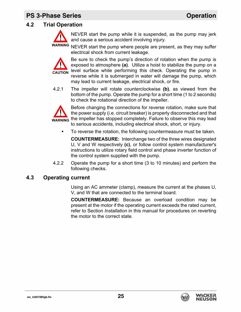
4.2 Trial OperationNEVER start the pump while it is suspended, as the pump may jerkand cause a serious accident involving injury.NEVER start the pump where people are present, as they may sufferelectrical shock from current leakage.Be sure to check the pump’s direction of rotation when the pump isexposed to atmosphere (a). Utilize a hoist to stabilize the pump on alevel surface while performing this check. Operating the pump inreverse while it is submerged in water will damage the pump, whichmay lead to current leakage, electrical shock, or fire.
4.2.1 The impeller will rotate counterclockwise (b), as viewed from thebottom of the pump. Operate the pump for a short time (1 to 2 seconds)to check the rotational direction of the impeller.
Before changing the connections for reverse rotation, make sure thatthe power supply (i.e. circuit breaker) is properly disconnected and thatthe impeller has stopped completely. Failure to observe this may leadto serious accidents, including electrical shock, short, or injury.
• To reverse the rotation, the following countermeasure must be taken.
COUNTERMEASURE: Interchange two of the three wires designatedU, V and W respectively (c), or follow control system manufacturer'sinstructions to utilize rotary field control and phase inverter function ofthe control system supplied with the pump.
4.2.2 Operate the pump for a short time (3 to 10 minutes) and perform thefollowing checks.
4.3 Operating currentUsing an AC ammeter (clamp), measure the current at the phases U,V, and W that are connected to the terminal board.COUNTERMEASURE: Because an overload condition may bepresent at the motor if the operating current exceeds the rated current,refer to Section Installation in this manual for procedures on revertingthe motor to the correct state.
WARNING
CAUTION
WARNING
wc_tx001985gb.fm 25

Operation PS 3-Phase Series
4.4 Operating voltageUse an AC voltmeter (tester) to measure the voltage at the terminalboard.Power supply voltage tolerance = within ±5% of the rated voltageCOUNTERMEASURE: If the power supply voltage deviates from thetolerance value, the deviation may be caused by the capacity of thepower supply or the extension cable that is used. Refer to SectionElectrical Wiring in this manual to provide correct voltage.
4.5 Vibration If the pump generates a considerable amount of vibration, noise, orsmell, disconnect the power supply immediately and contact the dealerwhere you purchased the equipment, or the Wacker Neuson salesoffice in your area.
4.6 OperationThe pump may be extremely hot during operation. To prevent burns,do not touch the pump with bare hands.Do not insert your finger or a stick into the pump’s inlet opening. Doingso may cause injury, electrical shock, short, or fire.When the pump is not used for a long time, make sure that the powersupply (such as a breaker) is properly disconnected. If the wiringinsulation deteriorates with the power supply connected, it may causecurrent leakage, electrical shock, or fire.Pay attention to the water level during the pump operation. The pumpwill become damaged if it is allowed to operate dry.Note: Refer to “Water Level During Operation” at the end of thissection.The pump is equipped with an internal motor protective device (circlethermal protector).
CAUTION
U V W G
wc gr000333
cb
a
CAUTION
26 wc_tx001985gb.fm

PS 3-Phase Series Operation
4.7 Motor ProtectorDuring inspection and repair, disconnect the power supply to avoidstarting the pump unintentionally. Failure to disconnect the powersupply may lead to serious accidents including electrical shock, ashort, and injury.During a power outage, disconnect the power supply to the pump.Unintentional operation of the pump after power resumption would beextremely dangerous to people around the pump.Unless the cause of a problem is removed, the pump will repeat thestop-and-go cycle, eventually resulting in damage to the pump, andcausing current leakage and electrical shock. Therefore, after verifyingthat the power supply is disconnected, find and correct the cause of theproblem through inspection and repair.DO NOT operate the pump at unusually low head, or when the straineris clogged with debris. Doing so will prevent the pump from attainingits full potential, and may also generate abnormal noise and vibrationand cause damage to the pump, which may lead to current leakage,electrical shock, and fire.To protect the motor, if a current overload occurs in the motor or if themotor overheats under the conditions given below, the pump will stopautomatically, regardless of the water level during operation.• Extreme fluctuation of power supply voltage
• Pump operated under overload condition
• Pump operated at open phase or binding condition
Water Level During OperationDo not operate the pump below Continuous Running Water Level (a),as doing so will damage the pump, causing current leakage andelectrical shock.The table below shows the water level during operation by output.Make sure that the water level will not be under these levels.
Model Continuous Running Water Level
PS2 1503PS2 2203
PS3 1503PS3 2203
120 mm (4¾”)
PS2 3703PS4 3703PS4 5503
PS3 3703PS3 5503
150 mm (6”)
PS4 7503HHPS4 11003HH
PS4 7503HFPS4 11003HF
190 mm (7½”)
WARNING
CAUTION
CAUTION
wc_tx001985gb.fm 27

Operation PS 3-Phase Series
4.8 Emergency Shutdown ProcedureIf a breakdown/accident occurs while the machine is operating, follow the procedure below.
4.8.1 Turn off the pump.4.8.2 Disconnect the power supply.4.8.3 Contact the rental yard or machine owner.
a
wc_gr000335
28 wc_tx001985gb.fm

PS 3-Phase Series Maintenance
5 Maintenance5.1 Periodic Maintenance ScheduleThe table below lists basic machine maintenance. Tasks designated with check marks may be performed by the operator. Tasks designated with square bullet points require special training and equipment.
Pump Monthly Every3000 hrs.
Every 6000 hrs.
Every2–5 years
Measure insulation resistance.Reference insulation resistance = 1MW or greater. (1)
Measure operating current. Compare with rated current.
Measure supply voltage. Compare with allowable range (within ±5% of rated voltage).
Pump inspection. A noticeable drop in performance may indicate wear in the impeller, etc., or else clog-ging of the strainer, etc. Remove the clogged debris and replace any worn parts.
Lubricant inspection.
Change lubricant.
Designated lubricant: SAE 10W/20W. (2)
Change mechanical seal. (3)
Overhaul. This should be carried out even if there are no problems with the pump. The frequency depends on how continuously the pump is in use. (4)
(1) If the insulation resistance has become noticeably lower than the previous inspection, an inspection of the motor will be necessary.
(2) See Lubricant Inspection and Change in this section.(3) Specialized knowledge is required for inspecting and replacing the mechanical seal. Consult
with your nearest dealer or Wacker Neuson representative.(4) Consult with your nearest dealer or Wacker Neuson representative regarding overhauls.
wc_tx000124gb.fm 29

Maintenance PS 3-Phase Series
5.2 Maintenance and InspectionRegular maintenance and inspections are a necessity for continuedefficient functioning of the pump. If any abnormal conditions arenoticed, refer to the Troubleshooting section and take correctivemeasures immediately. It is recommended that a spare pump be keptready in case of any problems.Prior to inspectingBefore inspecting the pump, make certain the power supply (circuitbreaker, etc.) is turned off. Then, unplug the cable assembly from thereceptacle or detach it from the terminals. Failure to follow thisprecaution may result in a serious accident from electrical shock orunexpected starting of the pump motor.
5.2.1 Washing the pump
Remove accumulated matter from the surface of the pump and washit with clean water. Take special care to remove any debris from theimpeller.
5.2.2 Inspecting the pump exteriorLook for any peeling or chipped paint, and make sure the nuts andbolts are fastened tightly. Any cracks in the surface should be repairedby cleaning that area, drying it and then applying a touch-up coating.Note: Touch-up paint is not supplied. Note that some kinds of damageor looseness may require that the unit be disassembled for repairs.Please consult your nearest dealer or Wacker Neuson representative.
5.3 StorageWhen the pump is out of use for an extended period, wash it and dry itthoroughly, then store it indoors.Note: Always run a test operation before putting the pump back intoservice. If the pump is left in the water, it should be run a minimum of once aweek.
WARNING
30 wc_tx000124gb.fm

PS 3-Phase Series Maintenance
5.4 Lubricant Inspection and Changing Procedures• Inspection interval: Every 3,000 hours or 6 months, whichever comes first.
• Changing interval: Every 6,000 hours or 12 months, whichever comes first.
• Designated lubricant: Turbine oil VG32 (SAE 10W/20W).
• Lubricant capacity: Specified capacity (Refer to the table, “Specified Lubricant Capacity”.)
Inspecting LubricantRemove the oil plug and take out a small amount of oil. The oil can beextracted easily by tilting the pump so that the oil plug faces downward.If the oil appears discolored or intermixed with water, a likely cause isa defective shaft-sealing device (i.e. mechanical seal), which requiresthat the pump be disassembled and repaired.
Changing LubricantRemove the oil plug and drain the oil completely. Pour a specifiedvolume of oil into the oil filler inlet.Note: The drained oil must be disposed of by waste disposalcontractors in compliance with the laws of the locale where the pumpis being used.
Ref. Description Ref. Description
1 Oil Inlet 3 Oil Plug
2 Gasket 4 Allen Wrench
wc gr000336
wc_tx000124gb.fm 31

Maintenance PS 3-Phase Series
Note: The gasket and the O-ring for the oil plug must be replaced witha new part at each oil inspection and change.5.5 Replacement PartsThe table lists the parts that need to be replaced periodically. Replacethese using the recommended frequency as a guideline.
Model Specified Lubricant Capacity
PS2 1503PS2 2203
PS3 1503PS3 2203
740 ml (25.0 fl.oz.)
PS2 3703PS4 3703
PS3 3703 960 ml (32.5 fl.oz.)
PS4 5503 PS3 5503 1100 ml (37.2 fl.oz.)
PS4 7503HHPS4 11003HH
PS4 7503HFPS4 11003HF
760 ml (25.7 fl.oz.)
Part Replacement Frequency
Mechanical seal Lubrication oil discolored
Lubricant (SAE 10W/20W) Every 6,000 hours or 12 months, whichever comes first.
Gasket and O-ring Each time pump is disassembled or inspected.
Oil seal (1.5 to 5.5 kW)[2 to 2.7 HP]
Each time pump is disassembled or inspected or if the sealing lip is worn
Ring-sealing (7.5/11 kW)[10/15 HP]
When it becomes worn.
Sleeve (except 3.7/5.5 kW)[5 / 7.5 HP]
When it becomes worn.
32 wc_tx000124gb.fm

PS 3-Phase Series Maintenance
5.6 Disassembly and ReassemblyPrior to Disassembling and Reassembling Before disassembling and reassembling the pump, be sure that thepower supply (i.e. circuit breaker) is disconnected, and remove thecable assembly from the terminal board. To prevent serious accidents,DO NOT perform a conducting test during disassembly andreassembly. Be sure to perform a trial operation when starting the pump after areassembly. If the pump was assembled improperly, it may lead toabnormal operation, electrical shock, or water damage.This section explains the disassembly and reassembly processes thatare involved up to the casing (or oil casing, in the case of 7.5 kW and11 kW models. Refer to the structural drawing for the respective modelbefore disassembling. Operations involving the disassembly andreassembly of the sealing portion (i.e. mechanical seal) and of themotor require a specialized facility including vacuum and electricalequipment. For these operations, contact the dealer from whom youpurchased the equipment, or the Wacker Neuson sales office in yourarea.
WARNING
CAUTION
wc_tx000124gb.fm 33

Maintenance PS 3-Phase Series
5.7 Graphic (1.5 kW, 2.2 kW, 3.7 kW, 5.5 kW)12
3
4
5
AA
CC
8
9
10
BB
DD
11
12
13
14
151617
18
19
20
21
22
2324
wc_gr000337
34 wc_tx000124gb.fm

PS 3-Phase Series Maintenance
5.8 Graphic Components5.9 Disassembly Procedure for 1.5 kW, 2.2 kW, 3.7 kW and 5.5 kW Models
Note: Before disassembling, be sure to drain the lubricant from thepump.The breakdown of pump shown is based on the construction of 1.5 kWmodel PS2 (3) 1503. However, 2.2 kW, 3.7 kW and 5.5 kW PS three-phase models have the same construction as PS2 1503 and PS31503, except that the sleeve (12) will not be applied to the 3.7 kW and5.5 kW models.
5.9.1 Removing the strainer (22):Remove the nut (24) and the washer (23) from the bottom and removethe strainer (22) from the pump.
5.9.2 Removing the suction cover:Remove the bolt and the nut (except 1.5 kW/2.2 kW), washer (20), andthe stud bolt (21), and remove the suction cover (19), from the pump.
Ref. Description Ref. Description
1 Bolt 12 Sleeve
2 Lock washer 13 Shim
3 Gasket 14 Impeller
4 Oil plug 15 Thread cover
5 Mechanical seal 16 Lock washer
AA Screw 17 Acorn nut
BB Oil Lifter 18 Gasket
CC Screw 19 Suction cover
DD Retaining plate 20 Lock washer
8 O-Ring 21 Stud bolt
9 Gasket 22 Strainer
10 Volute 23 Washer
11 Oil seal 24 Nut
wc_tx000124gb.fm 35

Maintenance PS 3-Phase Series
5.9.3 Removing the impeller (14):An impeller puller is available from manufacturer.Using a box wrench, remove the acorn nut (17), lockwasher (16), andthread cover (15); then remove the impeller (14), sleeve (12) (except3.7 kW/5.5 kW) from the main shaft. A worn impeller may have sharp edges that can cause injury, andshould be handled with care.
5.9.4 If necessary, remove the volute (10) and remove the mechanical seal(5). After removing the bolt (1) and the lockwasher (2), remove the volute(10) from the pump. At this time, be careful not to damage the slidingsurface of the mechanical seal (5). Remove the mechanical seal (5)from the main shaft.Note: Also refer to the “Mechanical Seal Handling Procedure” thatcomes with the mechanical seal sold separately as a spare part.See Graphic: wc_gr000337
Reassembly Procedure5.9.1 The reassembly procedure is the reverse sequence of disassembly.
Note: After completing reassembly, do not forget to pour the specifiedamount of lubricant into the pump.Note: The gaskets and O-rings must be replaced with new parts. Alsoreplace any parts that are worn or damaged.
5.9.2 Using a clean rag without lubricant, wipe the sliding surface of themechanical seal (5). Apply lubricant to the outer circumference of thecushion rubber to facilitate insertion.Note: For further details on how to install the mechanical seal (5), referto the “Mechanical Seal Handling Procedure” that comes with themechanical seal (5) that is sold separately as a spare part.
5.9.3 After installing the impeller (14), and after completing the reassembly,check that the impeller (14) rotates smoothly and that it does not comein contact with the suction cover (19).
5.9.4 To make sure that the pump operates normally, perform a trialoperation before placing the pump back into service.
WARNING
36 wc_tx000124gb.fm

PS 3-Phase Series Maintenance
5.10 Graphic (7.5 kW, 11 kW)wc_gr000338
12
3
10
89
BB
DD
AA
CC
11
6
7
1213
15
1617
14
1819
20
212223
24
25
2627
28
29
30
31
3233
wc_tx000124gb.fm 37

Maintenance PS 3-Phase Series
5.11 Graphic ComponentsRef. Description Ref. Description
1 Bolt 17 O-Ring
2 Lock washer 18 Sealing ring
3 Mechanical seal 19 Shim
AA Screw 20 Impeller
BB Oil Lifter 21 Thread cover
CC Screw 22 Nut
DD Retaining plate 23 Acorn nut
6 O-Ring 24 Gasket
7 Gasket 25 Suction cover
8 Oil casing 26 Lock washer
9 Gasket 27 Bolt
10 Oil plug 28 Lock washer
11 Lock washer 29 Stud bolt
12 Bolt 30 Strainer
13 Sleeve 31 Plate
14 Volute 32 Lock washer
15 Lock washer 33 Nut
16 Bolt
38 wc_tx000124gb.fm

PS 3-Phase Series Maintenance
5.12 Disassembly Procedure for 7.5 kW and 11 kWNote: Before disassembling, be sure to drain the lubricant from thepump.The breakdown of pump shown is based on the construction of 7.5 kWmodel PS4 7503HH/HF.
5.12.1 Removing the plate (31) and the strainer (30):After removing the nut (33) and the washer (32) from the bottom,remove the plate (31) and the strainer (30) from the pump.
5.12.2 Removing the suction cover (25):After removing the bolt (27), washer (26), stud bolt (29), and thelockwasher (28), remove the suction cover (25) from the pump.
5.12.3 Removing the impeller (20):Using a box wrench, remove the acorn nut (23), nut (22), and thethread cover (21); then remove the impeller (20) and the sleeve (13)from the main shaft. A worn impeller may have sharp edges that can cause injury, andshould be handled with care.
5.12.4 Removing the volute (14):After removing the bolt (16) and the lockwasher (15), remove thevolute (14) from the pump.
5.12.5 Remove the oil casing (8) if necessary, and remove the mechanicalseal (3). After removing the bolt (12) and the lockwasher (11), removethe oil casing (8) from the pump. At this time, be careful not to damagethe sliding surface of the mechanical seal (3). Remove the mechanicalseal (3) from the main shaft.Note: Also refer to the “Mechanical Seal Handling Procedure” thatcomes with the mechanical seal that is sold separately as a spare part.
WARNING
wc_tx000124gb.fm 39

Maintenance PS 3-Phase Series
Reassembly Procedure5.12.1 The reassembly procedure is the reverse sequence of disassembly.
Note: After completing reassembly, do not forget to pour the specifiedamount of lubricant into the pump.Note: The gaskets and O-rings must be replaced with new parts. Alsoreplace any parts that are worn or damaged.
5.12.2 Using a clean rag without lubricant, wipe the sliding surface of themechanical seal (3). Apply lubricant to the outer circumference of thecushion rubber to facilitate insertion.Note: For further details on how to install the mechanical seal (3), referto the “Mechanical Seal Handling Procedure” that comes with themechanical seal (3) that is sold separately as a spare part.
5.12.3 After installing the impeller (20), and after completing the reassembly,check that the impeller (20) rotates smoothly and that it does not comein contact with the suction cover (25).
5.12.4 To make sure that the pump operates normally, perform a trialoperation before placing the pump back into service.
40 wc_tx000124gb.fm
PS 3-Phase Series Maintenance
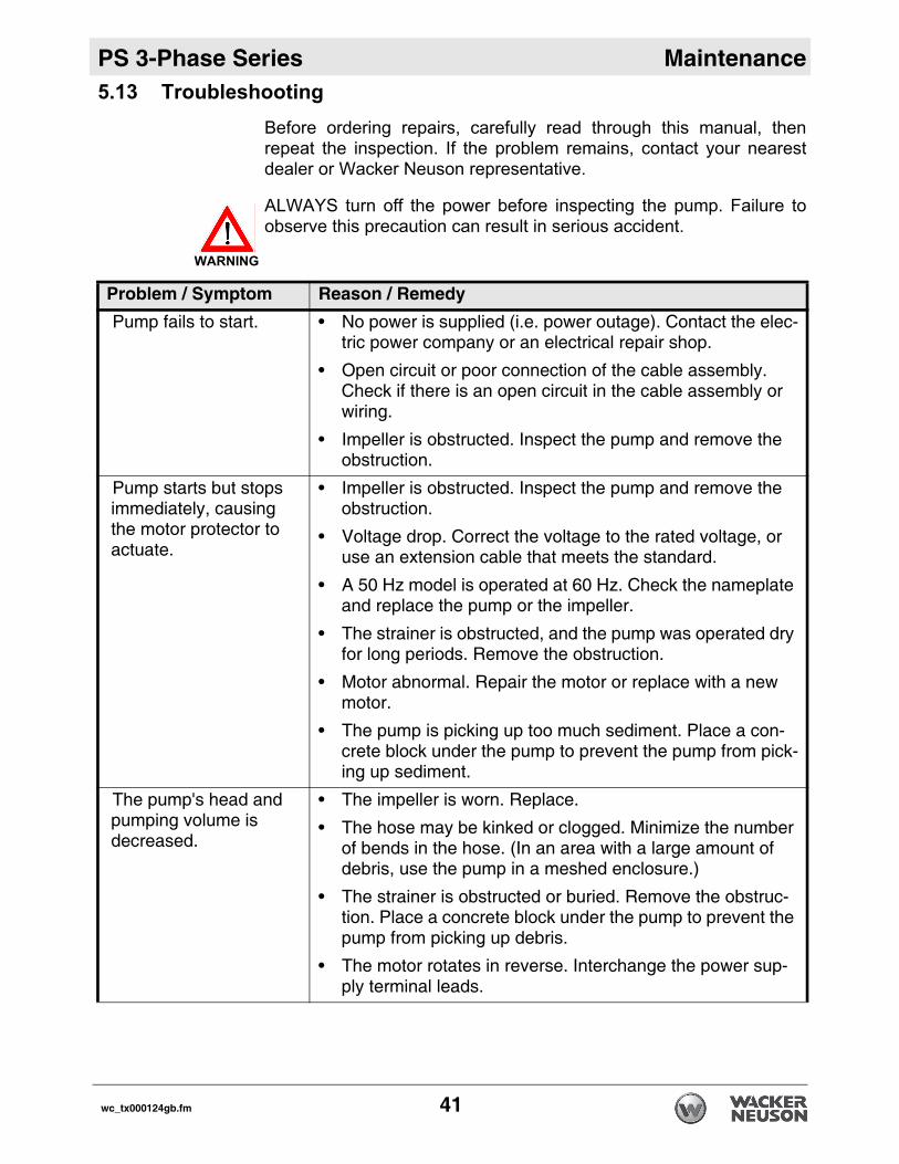
5.13 TroubleshootingBefore ordering repairs, carefully read through this manual, thenrepeat the inspection. If the problem remains, contact your nearestdealer or Wacker Neuson representative.
ALWAYS turn off the power before inspecting the pump. Failure toobserve this precaution can result in serious accident.
Problem / Symptom Reason / RemedyPump fails to start. • No power is supplied (i.e. power outage). Contact the elec-
tric power company or an electrical repair shop.
• Open circuit or poor connection of the cable assembly. Check if there is an open circuit in the cable assembly or wiring.
• Impeller is obstructed. Inspect the pump and remove the obstruction.
Pump starts but stops immediately, causing the motor protector to actuate.
• Impeller is obstructed. Inspect the pump and remove the obstruction.
• Voltage drop. Correct the voltage to the rated voltage, or use an extension cable that meets the standard.
• A 50 Hz model is operated at 60 Hz. Check the nameplate and replace the pump or the impeller.
• The strainer is obstructed, and the pump was operated dry for long periods. Remove the obstruction.
• Motor abnormal. Repair the motor or replace with a new motor.
• The pump is picking up too much sediment. Place a con-crete block under the pump to prevent the pump from pick-ing up sediment.
The pump's head and pumping volume is decreased.
• The impeller is worn. Replace.
• The hose may be kinked or clogged. Minimize the number of bends in the hose. (In an area with a large amount of debris, use the pump in a meshed enclosure.)
• The strainer is obstructed or buried. Remove the obstruc-tion. Place a concrete block under the pump to prevent the pump from picking up debris.
• The motor rotates in reverse. Interchange the power sup-ply terminal leads.
WARNING
wc_tx000124gb.fm 41

Maintenance PS 3-Phase Series
The pump generates noise or vibration.
• The bearing of the motor may be damaged. To replace the bearing, contact the dealer from whom you purchased the equipment, or the Wacker Neuson sales office in your area.
Problem / Symptom Reason / Remedy
42 wc_tx000124gb.fm

PS 3-Phase Series Technical Data
6 Technical Data6.1 Standard Specifications
Applicable Liquids, Consistency and Temperature
Work drainage and Sand-Carrying Water0–40°C (32–104°F)
Pump Impeller Open Type
Shaft Seal Double Mechanical Seal
Bearing Shielded Ball Bearing
Motor Specification Dry Submersible Induction Motor (2-Pole)
Insulation Class B: 7.5 to 11 kWClass E: 1.5 to 5.5 kW
Protection System Circle Thermal Protector
Lubricant SAE 10W/20WSuch as:–Turbine Oil ISO VG #32–Shell Victrolia Oil #27–British Pet Energol THB #32–Gulf Paramount #32–Tellus #T22 Shell Oil–Shell Turbo T32
Connection Coupling (Barb, BSP, QD)Refer to BOM Product Matrix in Parts Section
wc_td000041gb.fm 43

Technical Data PS 3-Phase Series
6.2 Operating Specifications*The weight (mass) given above is the operating weight of the pump itself, not including the cable assembly.
PS 2 1503 PS 3 1503 PS 2 2203 PS 3 2203
Pump
Discharge mm (in.) 50 (2) 80 (3) 50 (2) 80 (3)
Phase 3 3 3 3
Starting Method Direct Online
Output kW (Hp) 1.5 (2) 1.5 (2) 2.2 (3) 2.2 (3)
Rated Current A(V)
3.4(400)
5.5(400)
Maximum Head m (ft.) 21.5 (71) 14.4 (47) 26 (85) 20.4 (67)
Maximum Capacity L/min(GPM)
430 (114)
670(177)
500(132)
800(211)
Solid Size Capacity mm (in.) 8.5 (0.3) 8.5 (0.3) 8.5 (0.3) 8.5 (0.3)
Weight* Kg (lbs.) 29 (64) 29 (64) 32 (71) 32 (71)
44 wc_td000041gb.fm

PS 3-Phase Series Technical Data
*The weight (mass) given above is the operating weight of the pump itself, not including the cable assembly.
PS 2 3703 PS 3 3703 PS 4 3703
Pump
Discharge mm (in.) 50 (2) 80 (3) 100 (4)
Phase 3 3 3
Starting Method Direct Online
Output kW (Hp) 3.7 (5) 3.7 (5) 3.7 (5)
Rated Current A(V)
7.5(400)
Maximum Head m (ft.) 36.5 (120) 29 (95) 18 (59)
Maximum Capacity
L/min(GPM)
450 (119)
900 (238)
1440(380)
Maximum Pressure
psi 50 44 26.4
Solid Size Capacity
mm (in.) 8.5 (0.3) 8.5 (0.3) 8.5 (0.3)
Weight* Kg (lbs.) 55 (121) 55 (121) 55 (121)
wc_td000041gb.fm 45

Technical Data PS 3-Phase Series
*The weight (mass) given above is the operating weight of the pump itself, not including the cable assembly.
PS 3 5503 PS 4 5503
Pump
Discharge mm (in.) 80 (3) 100 (4)
Phase 3 3
Starting Method Direct Online
Output kW (Hp) 5.5 (7.5) 5.5 (7.5)
Rated Current A(V)
10.8(400)
Maximum Head m (ft.) 32 (105) 22.5 (74)
Maximum Capacity L/min (GPM) 1100(291)
1750(462)
Maximum Pressure psi 54 34.6
Solid Size Capacity mm (in.) 8.5 (0.3) 8.5 (0.3)
Weight* Kg (lbs.) 66 (146) 66 (146)
46 wc_td000041gb.fm
PS 3-Phase Series Technical Data
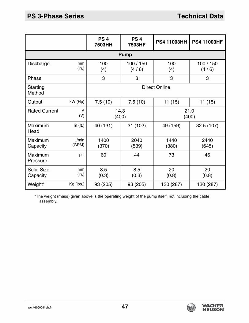
*The weight (mass) given above is the operating weight of the pump itself, not including the cable assembly.
PS 4 7503HH
PS 4 7503HF PS4 11003HH PS4 11003HF
Pump
Discharge mm(in.)
100 (4)
100 / 150 (4 / 6)
100 (4)
100 / 150 (4 / 6)
Phase 3 3 3 3
Starting Method
Direct Online
Output kW (Hp) 7.5 (10) 7.5 (10) 11 (15) 11 (15)
Rated Current A(V)
14.3(400)
21.0(400)
Maximum Head
m (ft.) 40 (131) 31 (102) 49 (159) 32.5 (107)
Maximum Capacity
L/min(GPM)
1400 (370)
2040(539)
1440(380)
2440(645)
Maximum Pressure
psi 60 44 73 46
Solid Size Capacity
mm(in.)
8.5(0.3)
8.5(0.3)
20(0.8)
20(0.8)
Weight* Kg (lbs.) 93 (205) 93 (205) 130 (287) 130 (287)
wc_td000041gb.fm 47

Technical Data PS 3-Phase Series
Notes48 wc_td000041gb.fm


Wacker Neuson Produktion GmbH & Co. KG, Preußenstraße 41, D-80809 München, Tel.: +49-(0)89-3 54 02-0 Fax: +49 - (0)89-3 54 02-390Wacker Neuson Production Americas LLC, N92W15000 Anthony Ave., Menomonee Falls, WI 53051
Tel. : (262) 255-0500 Fax: (262) 255-0550 Tel.: (800) 770-0957Wacker Neuson Limited - Room 1701–03 & 1717–20, 17/F. Tower 1, Grand Century Place, 193 Prince Edward Road West, Mongkok, Kowloon, Hongkong.
Tel: (852) 3605 5360, Fax: (852) 2758 0032