operator’s manual professional torque...
TRANSCRIPT
OPERATOR’S MANUAL
PROFESSIONAL TORQUE TESTER PRO-TEST 60, 400 & 1500 SERIES 2 FOR USE WITH PRO-TEST’S FITTED WITH VERSION 37701.301 SOFTWARE
Part Number 34299 | Issue 4 | Original Instructions (English)
NORBAR TORQUE TOOLS LTD Beaumont Road, Banbury, Oxfordshire, OX16 1XJ UNITED KINGDOM Tel + 44 (0)1295 270333 Email [email protected]
NORBAR TORQUE TOOLS PTY LTD 45–47 Raglan Avenue, Edwardstown, SA 5039 AUSTRALIA Tel + 61 (0)8 8292 9777 Email [email protected]
NORBAR TORQUE TOOLS INC 36400 Biltmore Place, Willoughby, Ohio, 44094 USA Tel + 1 866 667 2279 Email [email protected]
NORBAR TORQUE TOOLS (NZ) LTD B3/269A Mt Smart Road Onehunga, Auckland 1061 NEW ZEALAND Tel + 64 9579 8653 Email [email protected]
NORBAR TORQUE TOOLS PTE LTD 194 Pandan Loop #07-20 Pantech Business Hub SINGAPORE 128383 Tel + 65 6841 1371 Email [email protected]
NORBAR TORQUE TOOLS (SHANGHAI) LTD E Building–5F, no. 1618 Yishan Road, Minhang District, Shanghai CHINA 201103 Tel + 86 21 6145 0368 Email [email protected]
NORBAR TORQUE TOOLS INDIA PVT. LTD Plot No A-168, Khairne Industrial Area, Thane Belapur Road, Mahape, Navi Mumbai – 400 709 INDIA Tel + 91 22 2778 8480 Email [email protected] www.norbar.com
© Norbar Torque Tools Ltd 2014


1
CONTENTS Introduction 2 Part Numbers Covered by This Manual 2 Assembly Diagram 2 Parts Included 3 Accessories 3 Features and Functions 4 Operating Instructions 5 Mounting Positions 5 Locating Display Housing 6 Connecting Power Supply 6 Switching ON 6 Selecting Measurement Units 7 Selecting Measurement Mode 7 Fitting Hex Drive Adapter 7 Operating Tool to be Calibrated / Tested 7 Set Up 8 Language 8 Limits 8 Units 9 Serial Port 9 Thresholds 9 Modes 9 Limits 10 ISO 6789:2003 10 NON ISO 6789:2003 11 Operation 11 Status Indication 11 Serial Port 12 Parameters 12 Hyper Terminal 12 Limit Output 13 Pin Connections 13 Data Output Example 13 Connector Type 13 Connecting Lead 13 Maintenance 14 Pro-Test Calibration 14 Cleaning 14 Disposal (Recycling considerations) 14 Specifications 15

2
INTRODUCTION
The Professional Torque Tester (Pro-Test) has been designed as an accurate, cost effective and easy to operate instrument for calibrating and testing all types of torque wrenches. Part Numbers Covered By This Manual
43218 – PRO-TEST 60 series 2 TRANSDUCER & DISPLAY 43219 – PRO-TEST 400 series 2 TRANSDUCER & DISPLAY 43220 – PRO-TEST 1500 series 2 TRANSDUCER & DISPLAY Assembly Diagram
Part
Number Description
29034 ¼” sq to 10 mm hex socket. 29067 ⅜” sq to 10 mm hex socket. 29120 ½” sq to 10 mm hex socket. 29079 ⅜” sq to 22 mm hex socket. 29134 ½” sq to 22 mm hex socket. 29189 ¾” sq to 22 mm hex socket. 29179 ¾” sq to 36 mm hex socket.
Part Number Model 43218 Pro-Test 60 43219 Pro-Test 400 43220 Pro-Test 1500
DIAL & ELECTRONIC
59999 . N∙m LO
5 9. 9 9 5 5 9. 9 9 6 5 9. 9 9 7 5 9. 9 9 8 5 9. 9 9 9 TARGET 59.9
UNITS
-
+
100%
ZERO %
(Optional accessory)
62198
38877
39264
25492
70
2 Holes Ø10
2 Holes M10
3
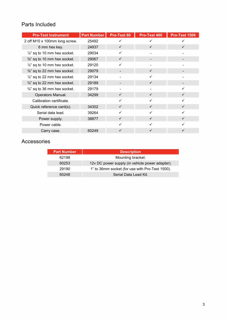
Parts Included
Pro-Test Instrument Part Number Pro-Test 60 Pro-Test 400 Pro-Test 1500 2 off M10 x 100mm long screw. 25492
6 mm hex key. 24937 ¼” sq to 10 mm hex socket. 29034 - - ⅜” sq to 10 mm hex socket. 29067 - - ½” sq to 10 mm hex socket. 29120 - - ⅜” sq to 22 mm hex socket. 29079 - - ½” sq to 22 mm hex socket. 29134 - - ¾” sq to 22 mm hex socket. 29189 - - ¾” sq to 36 mm hex socket. 29179 - -
Operators Manual. 34299 Calibration certificate.
Quick reference card(s). 34302 Serial data lead. 39264 Power supply. 38877 Power cable. Carry case. 60249
Accessories
Part Number Description 62198 Mounting bracket. 60253 12v DC power supply (in vehicle power adapter). 29190 1” to 36mm socket (for use with Pro-Test 1500). 60248 Serial Data Lead Kit.

4
FEATURES AND FUNCTIONS 3 sizes available covering the calibration ranges of:
1.2 to 60 N∙m. 8 to 400 N∙m. 30 to 1500 N∙m.
5 digit resolution. ISO 6789:2003 limit mode with single press selection for 20%, 60% & 100% target values. NON ISO 6789:2003 limit mode with user defined tolerances. The pictorial keys allow direct access to measurement modes. Serial Port Connector for data output to PC’s or printers. PRINT/NO PRINT ( PRINT/X PRINT) feature for control of serial port output. The last 5 readings taken are memorised on the display. SET UP menu’s for:
1. Language of operation, 2. Limits mode required, 3. Units of measurement enabled/disabled, 4. Serial port communication parameters, 5. Thresholds for ‘CLICK & CAM’ mode, 6. Modes of measurement enabled/disabled.
5
OPERATING INSTRUCTIONS NOTE: If the equipment is used in a manner not specified by the manufacturer, the protection
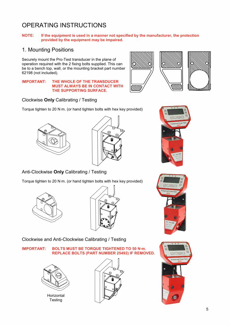
provided by the equipment may be impaired. 1. Mounting Positions Securely mount the Pro-Test transducer in the plane of operation required with the 2 fixing bolts supplied. This can be to a bench top, wall, or the mounting bracket part number 62198 (not included). IMPORTANT: THE WHOLE OF THE TRANSDUCER
MUST ALWAYS BE IN CONTACT WITH THE SUPPORTING SURFACE.
Clockwise Only Calibrating / Testing Torque tighten to 20 N∙m. (or hand tighten bolts with hex key provided) Anti-Clockwise Only Calibrating / Testing Torque tighten to 20 N∙m. (or hand tighten bolts with hex key provided) Clockwise and Anti-Clockwise Calibrating / Testing IMPORTANT: BOLTS MUST BE TORQUE TIGHTENED TO 50 N∙m.
REPLACE BOLTS (PART NUMBER 25492) IF REMOVED. Horizontal
Testing
6
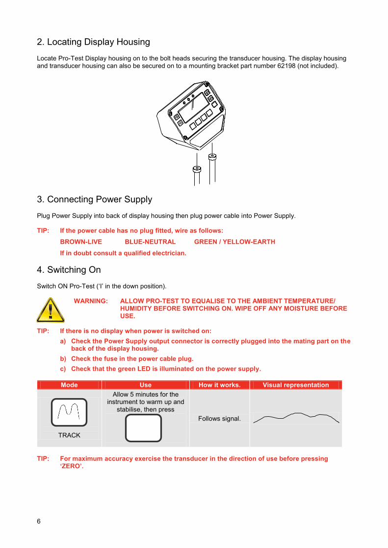
2. Locating Display Housing Locate Pro-Test Display housing on to the bolt heads securing the transducer housing. The display housing and transducer housing can also be secured on to a mounting bracket part number 62198 (not included).
3. Connecting Power Supply Plug Power Supply into back of display housing then plug power cable into Power Supply. TIP: If the power cable has no plug fitted, wire as follows:
BROWN-LIVE BLUE-NEUTRAL GREEN / YELLOW-EARTH
If in doubt consult a qualified electrician. 4. Switching On Switch ON Pro-Test (‘I’ in the down position).
WARNING: ALLOW PRO-TEST TO EQUALISE TO THE AMBIENT TEMPERATURE/ HUMIDITY BEFORE SWITCHING ON. WIPE OFF ANY MOISTURE BEFORE USE.
TIP: If there is no display when power is switched on:
a) Check the Power Supply output connector is correctly plugged into the mating part on the back of the display housing.
b) Check the fuse in the power cable plug. c) Check that the green LED is illuminated on the power supply.
Mode Use How it works. Visual representation
TRACK
Allow 5 minutes for the instrument to warm up and
stabilise, then press
Follows signal.
TIP: For maximum accuracy exercise the transducer in the direction of use before pressing
‘ZERO’.

7
5. Selecting Measurement Units Select required units of measurement. Pressing and releasing the ‘UNITS’ button will step onto the next available unit of measurement. TIP: Required units of measurement are not selectable.
a) Conversion cannot be displayed within available digits on display, thus conversion is not allowed.
b) Units required have been disabled. See SET UP. 6. Selecting Measurement Mode Press required button, see below:
Button Use How it works Visual representation
DIAL & ELECTRONIC
Bending beam wrenches &
Dial type wrenches.
Hold highest signal. Reset by pressing
CLICK & CAM
Preset (click type) wrenches.
Captures the FIRST PEAK of torque and displays this for the
selected AUTO RESET HOLD TIME before
automatically resetting. AUTO RESET HOLD TIME
TIP: Readings in CLICK & CAM mode are inconsistent. Change FIRST PEAK SENSITIVITY to be less sensitive, see THRESHOLDS menu in SET UP. 7. Fitting Hex Drive Adapter Fit adapter supplied to hex drive of transducer. Fit the tool to be calibrated / tested to the square drive of the adapter. 8. Operate Tool to Be Calibrated / Tested Apply force to tool smoothly (do not snatch). Follow instructions for torque tool being tested.
ZERO

8
SET UP
To enter SET UP, press ‘UNITS’ & ‘PRINT’ buttons simultaneously upon which the ‘SOFTWARE VERSION NUMBER’ will be displayed for 2 seconds. 1. Language
2. Limits TIP: If NON ISO 6789:2003 limit mode is enabled, ‘OK’ or ‘EXIT’ will go to the SET LIMITS
menu (shown below).
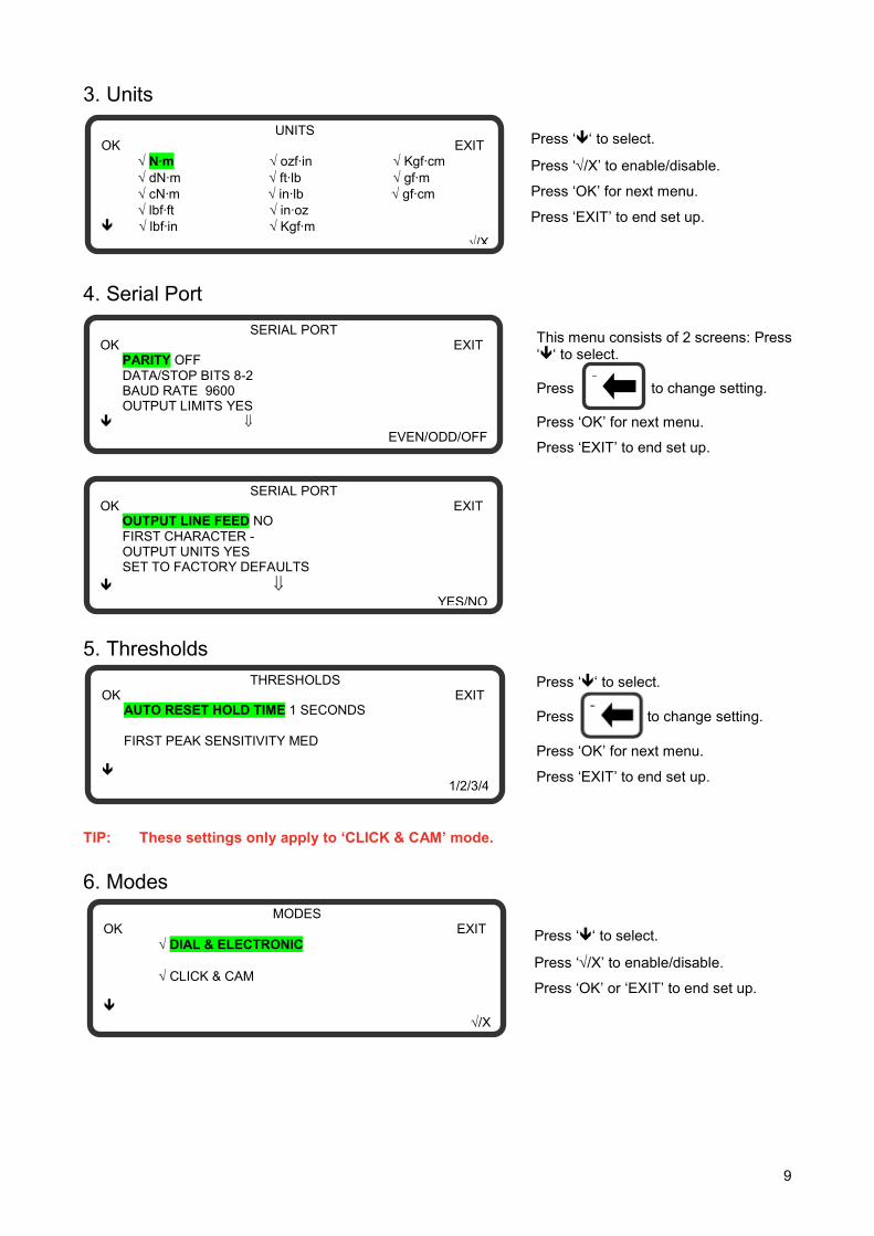
Press ‘‘ to select.
Press ‘OK’ for next menu.
Press ‘EXIT’ to end set up.
LANGUAGE OK EXIT ENGLISH DANSK FRANCAIS NEDERLANDS DEUTSCH SUOMI ITALIANO NORSK ESPANOL SVENSKA PORTUGUES
LIMITS OK EXIT
X ISO 6789:2003
X NON ISO 6789:2003
/X
SET LIMITS OK + UPPER LIMIT = TARGET + 4 % LOWER LIMIT = TARGET – 4 % -
TRACK
0.000 . N∙m UNITS
+
-
ZERO %
Press ‘‘ to select.
Press ‘/X’ to enable/disable.
Press ‘OK’ for next menu.
Press ‘EXIT’ to end set up.
Press ‘‘ to select.
Press ‘+’ or ‘-‘ to change the value displayed.
Press ‘OK’ for next menu.
Press ‘EXIT’ to end set up.
9
This menu consists of 2 screens: Press ‘‘ to select. Press to change setting. Press ‘OK’ for next menu.
Press ‘EXIT’ to end set up.
Press ‘‘ to select.
Press ‘/X’ to enable/disable.
Press ‘OK’ or ‘EXIT’ to end set up.
-
3. Units 4. Serial Port
5. Thresholds TIP: These settings only apply to ‘CLICK & CAM’ mode. 6. Modes
UNITS OK EXIT N∙m ozf∙in Kgf∙cm dN∙m ft∙lb gf∙m cN∙m in∙lb gf∙cm lbf∙ft in∙oz lbf∙in Kgf∙m
/X
MODES OK EXIT DIAL & ELECTRONIC CLICK & CAM
/X
SERIAL PORT OK EXIT PARITY OFF DATA/STOP BITS 8-2 BAUD RATE 9600 OUTPUT LIMITS YES
EVEN/ODD/OFF
SERIAL PORT OK EXIT OUTPUT LINE FEED NO FIRST CHARACTER - OUTPUT UNITS YES SET TO FACTORY DEFAULTS
YES/NO
Press ‘‘ to select.
Press ‘/X’ to enable/disable.
Press ‘OK’ for next menu.
Press ‘EXIT’ to end set up.
Press ‘‘ to select.
Press to change setting.
Press ‘OK’ for next menu.
Press ‘EXIT’ to end set up.
THRESHOLDS OK EXIT AUTO RESET HOLD TIME 1 SECONDS FIRST PEAK SENSITIVITY MED
1/2/3/4
10
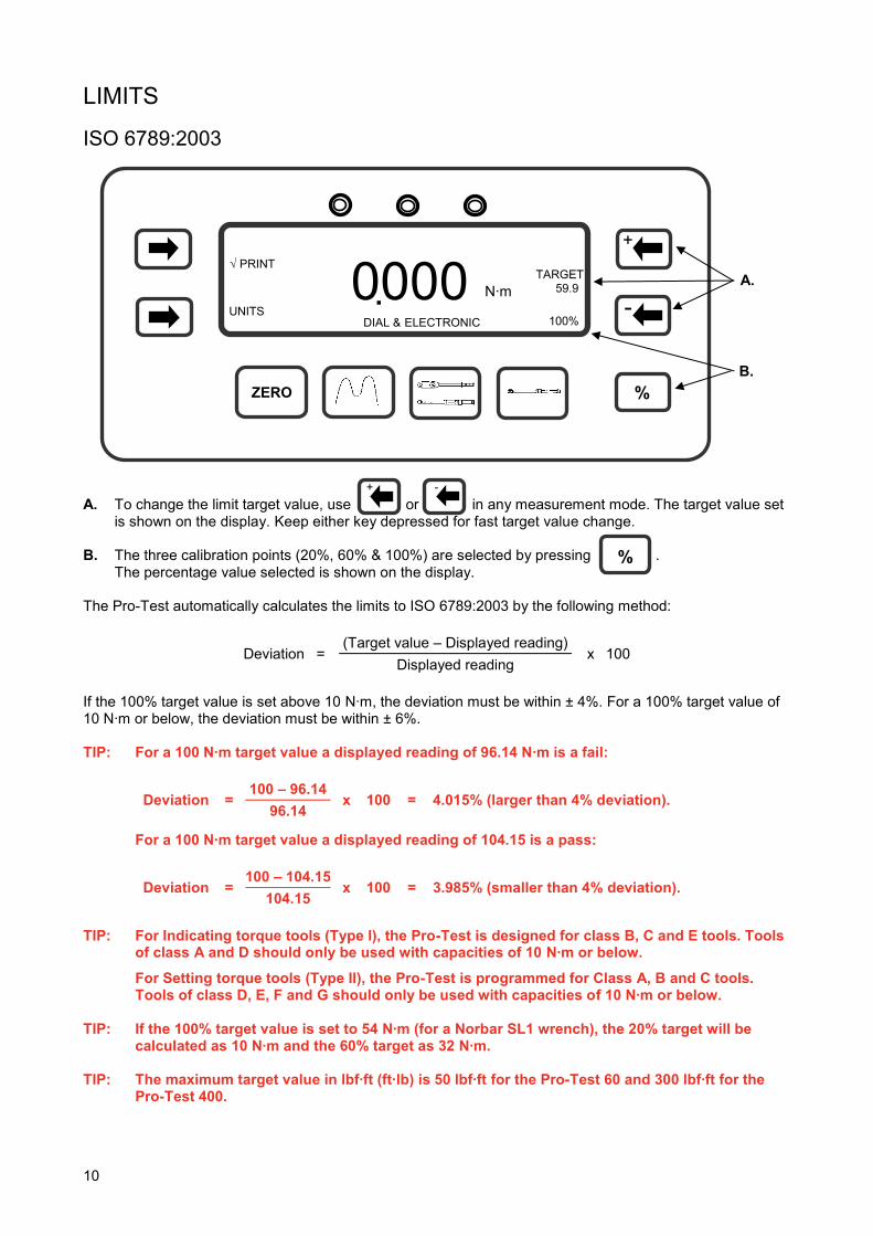
LIMITS ISO 6789:2003
A. To change the limit target value, use or in any measurement mode. The target value set
is shown on the display. Keep either key depressed for fast target value change. B. The three calibration points (20%, 60% & 100%) are selected by pressing . The percentage value selected is shown on the display. The Pro-Test automatically calculates the limits to ISO 6789:2003 by the following method:
Deviation = (Target value – Displayed reading)
x 100 Displayed reading
If the 100% target value is set above 10 N∙m, the deviation must be within ± 4%. For a 100% target value of 10 N∙m or below, the deviation must be within ± 6%. TIP: For a 100 N∙m target value a displayed reading of 96.14 N∙m is a fail:
Deviation = 100 – 96.14
x 100 = 4.015% (larger than 4% deviation). 96.14
For a 100 N∙m target value a displayed reading of 104.15 is a pass:
Deviation = 100 – 104.15
x 100 = 3.985% (smaller than 4% deviation). 104.15
TIP: For Indicating torque tools (Type I), the Pro-Test is designed for class B, C and E tools. Tools
of class A and D should only be used with capacities of 10 N∙m or below.
For Setting torque tools (Type II), the Pro-Test is programmed for Class A, B and C tools. Tools of class D, E, F and G should only be used with capacities of 10 N∙m or below.
TIP: If the 100% target value is set to 54 N∙m (for a Norbar SL1 wrench), the 20% target will be
calculated as 10 N∙m and the 60% target as 32 N∙m. TIP: The maximum target value in lbf∙ft (ft∙lb) is 50 lbf∙ft for the Pro-Test 60 and 300 lbf∙ft for the
Pro-Test 400.
DIAL & ELECTRONIC
0000 . N∙m
TARGET 59.9
UNITS
-
+
100%
ZERO %
A.
B.
+ -
%

11
NON ISO 6789:2003
NON ISO 6789:2003 limit mode allows the user to set upper and lower limits from 0% to 99% of the target value. A. To change the limit target value, use or in any measurement mode. The target value set
is shown on the display. Keep either key depressed for fast target value change. UPPER LIMIT = TARGET + % OF TARGET LOWER LIMIT = TARGET - % OF TARGET The default % OF TARGET is set to 4%. See the SET UP section to change the default value. Operation
Measurement Mode Limit Operation Track Limits follow signal and are not held.
Dial & Electronic Limits status is held until ‘ZERO’ is pressed. Click & Cam Limit status is held until after the auto reset timer has operated.
Limits are enabled to work in both the Clockwise and Counter clockwise directions. Status Indication
Torque Signal Display LED’s Serial Port Under lower limit LO Yellow LO
Within limits OK Green OK Above upper limit HI Red HI
DIAL & ELECTRONIC
0000 . N∙m
TARGET 59.9
UNITS
-
+
ZERO %
A.
+ -

12
SERIAL PORT The serial port is for sending data to a PC or serial printer.
Measurement Mode Data Output Operation Track When ‘PRINT’ is pressed.
Dial & Electronic When ‘ZERO’ is pressed after a peak has been captured. Click & Cam Automatically after a first peak has been captured.
The data can include direction indication, limit status, measured value, units of measurement and line feed. Parameters
Parameter Options Factory Defaults Comments Parity ODD, EVEN or OFF. ‘OFF’ The Parity Bit used for Parity Error.
Data-Stop bits 8-2, 8-1, 7-2, 7-1. ‘8-2’ The format per character. Baud rate 1200, 2400, 4800, 9600 or 19200. ‘9600’ The speed of data output.
Output Limits YES or NO. ‘YES’ Limit status sent before data. Output line feed YES or NO. ‘NO’ Line feed sent after data. First character - /+ & - /NONE. ‘-‘ Character sent before the data. Output units YES or NO. ‘YES’ Torque units sent after data.
SET TO FACTORY DEFAULTS. Reset all settings. Maximum number of characters per line = 24. Transmitted data voltage levels are between +5 to +9 volts and –5 to -9 volts. Configured as DTE (Data Terminal Equipment) and conforms to RS-232-C specifications. TIP: If the serial port is not communicating with other equipment:
a) Check that control word on the Pro-Test and the equipment receiving data match. b) Check that the baud rate is set to the same as the equipment receiving data. c) Check that the connecting lead is wired correctly at both ends if not using the lead
supplied. d) Check if the equipment receiving data requires the units of measurement inhibited or a
leading character. TIP: If the serial output is being overwritten set ‘OUTPUT LINE FEED’ to YES. Hyper Terminal The standard Hyper Terminal program found in Microsoft® Windows allows the user to view and store serial port output data.

13
Limit Output The serial port will output LO / OK / HI before the torque value when the limits are being used. Some software, including the Norbar ‘Torque Wrench Calibration Software’ (Part 37705.XXX), will not accept LO / OK / HI characters. The following table gives all options for the FIRST CHARACTER setting and the OUTPUT LIMITS setting:
First
Character Direction Limits Disabled Output Limits = NO
Limits Enabled Output Limits = YES
- Clockwise 1.0335 N∙m LO 1.0335 N∙m
Anti Clockwise -1.0335 N∙m LO -1.0335 N∙m
+ & - Clockwise +1.0335 N∙m LO +1.0335 N∙m
Anti Clockwise -1.0335 N∙m LO -1.0335 N∙m
NONE Clockwise 1.0335 N∙m LO 1.0335 N∙m
Anti Clockwise 1.0335 N∙m LO 1.0335 N∙m
Pin Connections
Pin No Function 1 Not Connected. 2 Received data (to Pro-Test). 3 Transmitted data (from Pro-Test). 4 Not Connected. 5 Signal ground 0V. 6 Not Connected. 7 Not Connected. 8 Not Connected. 9 Not Connected.
Data Output Example Code : DP=Decimal Point. CR=Carriage Return. SP=Space. Pro-Test with the serial port set to the factory defaults. Reading 1068.4 lbf∙ft (clockwise):
1 0 6 8 DP 4 SP l b f DP f t CR
Connector Type 9 way male ‘D’ type connector. Connecting Lead A 9 way female to 9 way female null modem connecting cable is included with the Pro-Test for connection to PC’s with a 9 way male connector. Alternatively use the Serial Data Lead Kit (part number 60248).

14
MAINTENANCE Pro-Test Calibration Your Pro-Test has been supplied with a certificate of calibration. To maintain the specified accuracy it is recommended that the Pro-Test is recalibrated at least once per year. Re-calibration should be carried out at Norbar or by a Norbar approved agent, where all the facilities to ensure the instrument is functioning at maximum accuracy are available. Cleaning Do not use abrasives or solvent based cleaners. Disposal (Recycling Considerations)
Component Material Back Panel Stainless Steel
Transducer Shaft Stainless Steel Transducer Housing Aluminium
Display Housing Aluminium For up to date disposal information, see our web site www.norbar.com.

15
SPECIFICATIONS Calibration range: 1.2 to 60 N∙m (Pro-Test 60). (2–100% of transducer capacity) 8 to 400 N∙m (Pro-Test 400).
30 to 1500 N∙m (Pro-Test 1500).
Resolution: 5 digits.
Torque conversions: To ‘BS 350:2004 Conversion factors for units’.
Display: 240 x 64 pixel dot matrix display. Update rate of three times per second (3Hz) in ‘TRACK’.
Accuracy: See calibration certificate.
Zero suppression: ± 1 LSD in ‘TRACK’ mode for Pro-Test 60. No suppression for Pro Test 400 & 1500. ’DIAL & ELECTRONIC’ and ‘CLICK & CAM’ mode suppressed from 0 to approximately 0.5% of transducer capacity.
Units of measurement: N∙m, dN∙m, cN∙m, lbf∙ft, lbf∙in, ozf∙in, ft∙lb, in∙lb, in∙oz, kgf∙m, kgf∙cm & gf∙m. PRO-TEST 60 also has gf∙cm available.
First peak sensitivity: 2.5%(High), 5%(Med), or 10%(Low) of reading.
Auto reset hold time: 1, 2, 3 or 4 seconds.
Trigger from setting: 1.55% of transducer capacity.
Limit hysteresis: 0.5% of transducer capacity.
Operating temperature range: +5°C to +40°C.
Storage temperature range: -20°C to +70°C.
Maximum operating humidity: 85% Relative Humidity at 30°C.
Power supply: 90 to 264 Volts a.c. at 50-60 Hz input. 9V, 300 mA D.C. output (centre positive).
Power consumption: 2.25 W - maximum.
Power cable: 2 meters (6 ft 6 ins) long minimum.
Power cable plug fuse (if fitted): 1 Amp.
Case materials / finish: Display and Transducer housings engineered in aluminium castings and finished in powder coated paint.
Environment: Indoor use within a light industrial environment.
Electromagnetic Compatibility: In conformance with EN 61326 : 1997. (EMC) Directive
Low voltage directive: In conformance with EN 61010-1 : 2001. To environmental conditions Pollution Degree 2 & Installation Category (Over voltage Category) II.
Mechanical overload: 150% of marked transducer capacity.
Dimensions: Transducer 106 (H) x 106 (W) x 185 (D). Display 128 (H) x 185 (W) x 102 (D).
Weight: Pro-Test 60 = 6.3 kg (13.9 lb). (Transducer with display) Pro-Test 400 = 6.4 kg (13.12 lb).
Pro-Test 1500 = 7.3 kg (15.11 lb). NOTE: Due to continuous improvement all specifications are subject to change without prior
notice.

16
NOTES

OPERATOR’S MANUAL
PROFESSIONAL TORQUE TESTER PRO-TEST 60, 400 & 1500 SERIES 2 FOR USE WITH PRO-TEST’S FITTED WITH VERSION 37701.301 SOFTWARE
Part Number 34299 | Issue 4 | Original Instructions (English)
NORBAR TORQUE TOOLS LTD Beaumont Road, Banbury, Oxfordshire, OX16 1XJ UNITED KINGDOM Tel + 44 (0)1295 270333 Email [email protected]
NORBAR TORQUE TOOLS PTY LTD 45–47 Raglan Avenue, Edwardstown, SA 5039 AUSTRALIA Tel + 61 (0)8 8292 9777 Email [email protected]
NORBAR TORQUE TOOLS INC 36400 Biltmore Place, Willoughby, Ohio, 44094 USA Tel + 1 866 667 2279 Email [email protected]
NORBAR TORQUE TOOLS (NZ) LTD B3/269A Mt Smart Road Onehunga, Auckland 1061 NEW ZEALAND Tel + 64 9579 8653 Email [email protected]
NORBAR TORQUE TOOLS PTE LTD 194 Pandan Loop #07-20 Pantech Business Hub SINGAPORE 128383 Tel + 65 6841 1371 Email [email protected]
NORBAR TORQUE TOOLS (SHANGHAI) LTD E Building–5F, no. 1618 Yishan Road, Minhang District, Shanghai CHINA 201103 Tel + 86 21 6145 0368 Email [email protected]
NORBAR TORQUE TOOLS INDIA PVT. LTD Plot No A-168, Khairne Industrial Area, Thane Belapur Road, Mahape, Navi Mumbai – 400 709 INDIA Tel + 91 22 2778 8480 Email [email protected] www.norbar.com
© Norbar Torque Tools Ltd 2014