operator's manual … · maximum torque n-m (kgf-m) 101.7 (10.4) ... (kubota 10-tooth)...
TRANSCRIPT

OPERATOR'S MANUAL
L3240·L3540·L4240·L5240·L5740
© KUBOTA Corporation 2011PRINTED IN JAPAN
READ AND SAVE THIS MANUAL
English (Australia)Code No. TD277-1974-1
L4240·L5240·L5740 with ROPSL3240·L3540MODELS
L4240·L5240·L5740 with CAB

KUBOTA Corporation is ···Since its inception in 1890, KUBOTA Corporation has grown to rank as one of the major firms in Japan.
To achieve this status, the company has through the years diversified the range of its products and services to a remarkable extent, until today, 19 plants and 16,000 employees produce over 1,000 different items, large and small.
All these products and all the services which accompany them, however, are unified by one central commitment. KUBOTA makes products which, taken on a national scale, are basic necessities. Products which are indispensable, products intended to help individuals and nations fulfill the potential inherent in their environment. For KUBOTA is the Basic Necessities Giant.
This potential includes water supply, food from the soil and from the sea, industrial development, architecture and construction, and transportation.
Thousands of people depend on KUBOTA's know-how, technology, experience and customer service. You too can depend on KUBOTA.
L3240/L3540/L4240L5240/L5740 (Australia)AS . F . 3 - 6 . 1 . AK
Abbreviations Definitions
ABBREVIATION LIST
This operator’s manual has been edited for global use.Please keep in mind, however, that some models discussed herein might not be available in your country.
Two Wheel Drive
Four Wheel Drive
American Petroleum Institute
American Society of Agricultural and Biological Engineers, USA
American Society for Testing and Materials, USA
Deutsches Institut für Normung, GERMANY
Dual Traction [4WD]
Feet Per Minute
Glide Shift Transmission
High Speed-Low Speed
Hydrostatic Transmission
Meters Per Second
Power Take Off
Right-hand and left-hand sides are determined by facing in the direction of forward travel
Roll-Over Protective Structures
Revolutions Per Minute
Revolutions Per Second
Society of Automotive Engineers, USA
Slow Moving Vehicle
2WD
4WD
API
ASABE
ASTM
DIN
DT
fpm
GST
Hi-Lo
HST
m/s
PTO
RH/LH
ROPS
rpm
r/s
SAE
SMV
FOREWORD
3SAFETY FIRST
IMPORTANT :
NOTE :
3 DANGER :
3 WARNING :
3 CAUTION :
Indicates an imminently hazardous situation which, if not avoided, will result in death or serious injury.
Indicates a potentially hazardous situation which, if not avoided, could result in death or serious injury.
Indicates a potentially hazardous situation which, if not avoided, could result in minor or moderate injury.
Indicates that equipment or property damage could result if instructions are not followed.
Gives helpful information.
Thank you very much for choosing the L series tractor.This operator's manual covers the operation, inspection and preventive maintenance instructions that is specific to the oceania models. For other information and instructions, refer to the separately issued operator's manual for the sister models. (L3240-3 to L5740-3)Please read both manuals carefully, to operate the machine properly and safety.Proper daily inspection, servicing and lubrication keeps your machine in good condition.
This symbol, the industry's ''Safety Alert Symbol'', is used throughout this manual and on labels on the machine itself to warn of the possibility of personal injury. Read these instructions carefully. It is essential that you read the instructions and safety regulations before you attempt to assemble or use this unit.

CONTENTS
SPECIFICATIONS....................................................................................................... 1SPECIFICATION TABLE [HST Type] ...................................................................... 1SPECIFICATION TABLE [Manual Transmission Type] ........................................... 3TRAVELING SPEEDS ............................................................................................. 5
HST Type..........................................................................................................................5Manual Transmission Type...............................................................................................5
OPERATING THE TRACTOR..................................................................................... 6STARTING............................................................................................................... 6
Turn Signal / Hazard Light Switch ....................................................................................6Horn Button.......................................................................................................................6Tractor Lights....................................................................................................................7
HYDRAULIC UNIT....................................................................................................... 8REMOTE HYDRAULIC CONTROL SYSTEM.......................................................... 8
Remote Control Valve.......................................................................................................8Remote Control Valve Lever.............................................................................................8
TIRES, WHEELS AND BALLAST................................................................................ 9TIRES....................................................................................................................... 9
Inflation Pressure..............................................................................................................9Dual Tires .........................................................................................................................9
WHEEL ADJUSTMENT ........................................................................................... 9Front Wheels (with 4 wheel drive) ..................................................................................10Rear Wheels ...................................................................................................................11
PERIODIC SERVICE................................................................................................. 12SERVICE AS REQUIRED...................................................................................... 12
Replacing Fuse...............................................................................................................12Replacing Light Bulb.......................................................................................................13

1SPECIFICATIONS
SPECIFICATIONS
SPECIFICATION TABLE [HST Type][ROPS and CAB models]ModelL3240 L3540 L4240 L5240 L5740
4WD
Engine
Model D1703-M-E2-HST1
D1803-M-E2-HST1
V2203-M-E2-HST1
V2403-M-TE2-HST1
V2403-M-TE2-HST2
Type Indirect injection vertical, water-cooled, 4-cycle diesel
Number of cylinders 3 4
Total displacement L 1.647 1.826 2.197 2.434
Bore and stroke mm 87 x 92.4 87 x 102.4 87 x 92.4 87 x 102.4
Net power* kW (HP) 23.9 (32.0) 26.1 (35.0) 31.3 (42.0) 38.8 (52.0) 42.5 (57.0)
PTO power* (factory observed)
kW (HP)/rpm
18.7 (25.1)/2700
20.9 (28.0)/2700
26.1 (35.0)/2700
33.6 (45.0)/2600
37.3 (50.0)/2700
Maximum torque N-m(kgf-m) 101.7 (10.4) 112.8 (11.5) 139.7 (14.2) 180.6 (18.4)
Battery capacity12V, RC: 123min, CCA: 490A
12V, RC: 133 min, CCA: 582A
Capacities
Fuel tank L 44 50 54
Engine crankcase (with filter) L 5.7 6.7 8.2 9.4
Engine coolant L 6.0 7.5 8.2
Transmission case L 42 43 45
Dimensions
Overall length(without 3p) mm 2960 3125 3250
Overall width(min. tread) mm 1520 1665 1570
Overall height
with ROPS mm 2385 2405 2490
with CAB mm --- 2295 2405
Wheel base mm 1805 1895 1915
Min. ground clearance mm 350 375 400
TreadFront mm 1150 1145 1340
Rear mm 1200, 1300, 1385, 1480 1285, 1435, 1530 1225, 1325, 1425, 1525
Weight
with ROPS kg 1540 1665 1745
with CAB kg --- 1815 1920
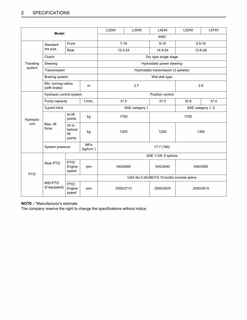
2 SPECIFICATIONS
NOTE : *Manufacturer's estimate The company reserve the right to change the specifications without notice.
Traveling system
Standardtire size
Front 7-16 8-16 9.5-16
Rear 12.4-24 14.9-24 13.6-28
Clutch Dry type single stage
Steering Hydrostatic power steering
Transmission Hydrostatic transmission (3 speeds)
Braking system Wet disk type
Min. turning radius (with brake) m 2.7 2.8
Hydraulic unit
Hydraulic control system Position control
Pump capacity L/min. 31.5 37.0 35.6 37.0
3-point hitch SAE category 1 SAE category 1, 2
Max. liftforce
At lift points kg 1700 1750
24 in. behind lift points
kg 1200 1250 1350
System pressure MPa(kgf/cm ) 17.7 (180)
PTO
Rear PTO
SAE 1-3/8, 6 splines
PTO/Engine speed
rpm 540/2685 540/2640 540/2590
MID-PTO(if equipped)
USA No.5 (KUBOTA 10-tooth) involute spline
PTO/Engine speed
rpm 2000/2715 2000/2670 2000/2615
ModelL3240 L3540 L4240 L5240 L5740
4WD

3SPECIFICATIONS
SPECIFICATION TABLE [Manual Transmission Type][ROPS model]
ModelL3240
4WD
Engine
Model D1703-M-E2-GST1
Type Indirect injection vertical, water-cooled, 4-cycle diesel
Number of cylinders 3
Total displacement L 1.647
Bore and stroke mm 87 x 92.4
Net power* kW (HP) 23.9 (32.0)
PTO power* (factory observed)
kW (HP)/rpm 19.8 (26.5)/2700
Maximum torque N-m(kgf-m) 101.7 (10.4)
Battery capacity 12V, RC: 123min, CCA: 490A
Capacities
Fuel tank L 44
Engine crankcase (with filter) L 5.7
Engine coolant L 6.0
Transmission case L 42
Dimensions
Overall length(without 3p) mm 2960
Overall width(min. tread) mm 1520
Overall height (with ROPS) mm 2385
Wheel base mm 1805
Min. ground clearance mm 350
TreadFront mm 1150
Rear mm 1200, 1300, 1385, 1480
Weight (with ROPS) kg 1475
Traveling system
Standardtire size
Front 7-16
Rear 12.4-24
Clutch Dry type single stage
Steering Hydrostatic power steering
Transmission 8 forward and 8 reverse fully synchronized main and shuttle transmission
Braking system Wet disk type
Min. turning radius (with brake) m 2.7

4 SPECIFICATIONS
NOTE : *Manufacturer's estimate The company reserve the right to change the specifications without notice.
Hydraulic unit
Hydraulic control system Position control
Pump capacity L/min. 31.5
Three point hitch SAE category 1
Max. liftforce
At lift points kg 1700
24 in. behind lift points
kg 1200
System pressure MPa(kgf/cm ) 17.7
PTO
Rear PTO
SAE 1-3/8, 6 splines
PTO/Engine speed
rpm 540/2550
MID-PTO(if equipped)
USA No.5 (KUBOTA 10-tooth) involute spline
PTO/Engine speed
rpm 2000/2580
ModelL3240
4WD
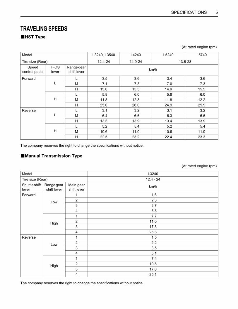
5SPECIFICATIONS
TRAVELING SPEEDSBHST Type
The company reserves the right to change the specifications without notice.
BManual Transmission Type
The company reserves the right to change the specifications without notice.
(At rated engine rpm)
Model L3240, L3540 L4240 L5240 L5740
Tire size (Rear) 12.4-24 14.9-24 13.6-28Speed
control pedalH-DS lever
Range gear shift lever km/h
ForwardL
L 3.5 3.6 3.4 3.6M 7.1 7.3 7.0 7.3H 15.0 15.5 14.9 15.5
HL 5.8 6.0 5.8 6.0M 11.8 12.3 11.8 12.2H 25.0 26.0 24.9 25.9
ReverseL
L 3.1 3.2 3.1 3.2M 6.4 6.6 6.3 6.6H 13.5 13.9 13.4 13.9
HL 5.2 5.4 5.2 5.4M 10.6 11.0 10.6 11.0H 22.5 23.2 22.4 23.3
(At rated engine rpm)
Model L3240Tire size (Rear) 12.4 - 24Shuttle shift lever
Range gear shift lever
Main gear shift lever
km/h
Forward
Low
1 1.62 2.33 3.74 5.3
High
1 7.72 11.03 17.84 26.3
Reverse
Low
1 1.52 2.23 3.54 5.1
High
1 7.42 10.53 17.04 25.1
6 OPERATING THE TRACTOR
OPERATING THE TRACTOR
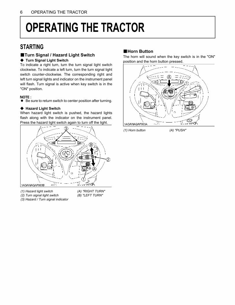
STARTINGBTurn Signal / Hazard Light SwitchC Turn Signal Light SwitchTo indicate a right turn, turn the turn signal light switchclockwise. To indicate a left turn, turn the turn signal lightswitch counter-clockwise. The corresponding right andleft turn signal lights and indicator on the instrument panelwill flash. Turn signal is active when key switch is in the"ON" position.A Be sure to return switch to center position after turning.
C Hazard Light SwitchWhen hazard light switch is pushed, the hazard lightsflash along with the indicator on the instrument panel.Press the hazard light switch again to turn off the light.
BHorn ButtonThe horn will sound when the key switch is in the "ON"position and the horn button pressed.
(1) Hazard light switch(2) Turn signal light switch(3) Hazard / Turn signal indicator
(A) "RIGHT TURN"(B) "LEFT TURN"
(1) Horn button (A) "PUSH"
7OPERATING THE TRACTOR
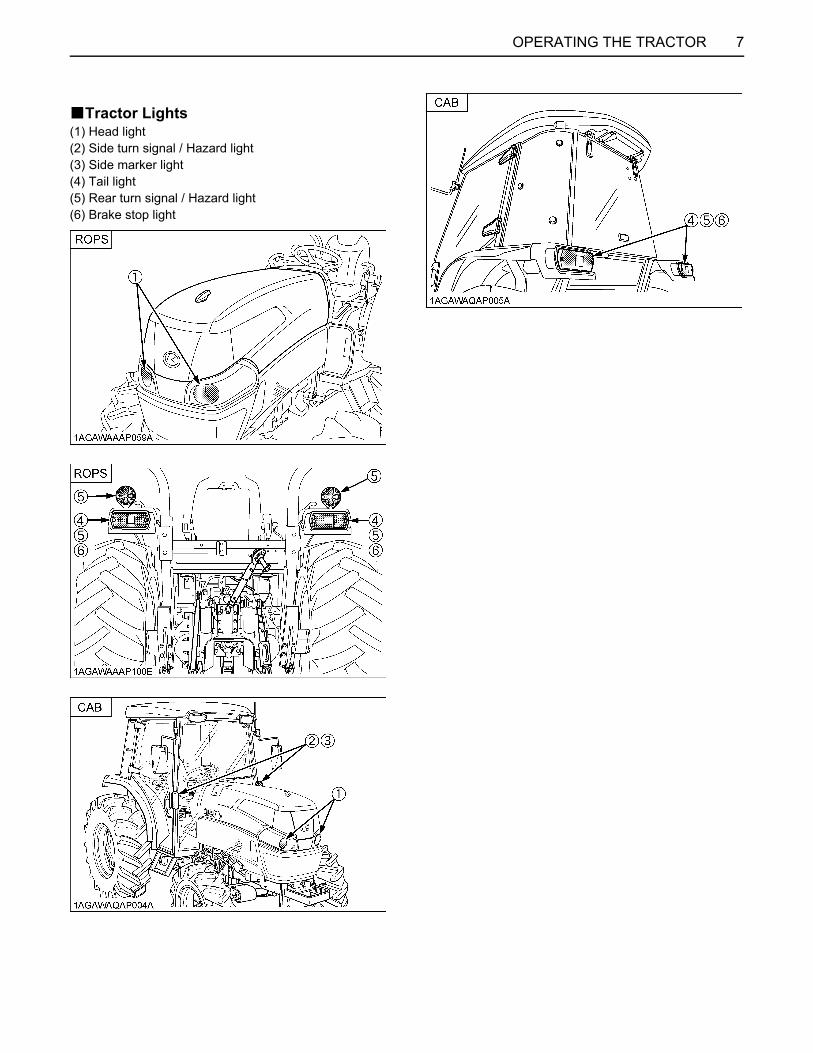
BTractor Lights(1) Head light(2) Side turn signal / Hazard light(3) Side marker light(4) Tail light(5) Rear turn signal / Hazard light(6) Brake stop light

8 HYDRAULIC UNIT
HYDRAULIC UNIT
REMOTE HYDRAULIC CONTROL SYSTEMThe hydraulic auxiliary control valves can be installed upto triple segments.BRemote Control ValveThere are two types of remote valves available for thesemodels.A Double acting valve:A Double acting valve with float position:
This valve may be placed in the float mode with thecontrol lever all the way forward. The cylinder is free toextend or retract, letting an implement such as aloader bucket follow the ground.
C Oceania model is equipped with double actingvalve as standard.
BRemote Control Valve LeverThe remote control valve lever directs pressurized oil flowto the implement hydraulic system.
A Do not hold the lever in the “REARWARD” or“FORWARD” position once the remote cylinder hasreached the end of the stroke, as this will cause oil toflow through the relief valve. Forcing oil through therelief valve for extended periods will overheat the oil.
A When using the tractor hydraulic system to power frontloader, do not operate boom and bucket cylinderssimultaneously.
Models Valve unit
L3240ROPSL3540ROPS ---
L4240ROPSL5240ROPSL5740ROPS
1
L4240CABL5240CABL5740CAB
2
(1) Remote control valve lever with Double acting valve (1)(2) Remote control valve lever with Double acting valve (2)
PressureReturning
Lever (1) X Y
Port[A] In Out
[B] Out In
Lever (2) X Y
Port[C] In Out
[D] Out In
Coupler size
Port [A] [B] [C] [D] PT 1/2

9TIRES, WHEELS AND BALLAST
TIRES, WHEELS AND BALLAST
TIRESTo avoid personal injury:A Do not attempt to mount a tire on a rim. This
should be done by a qualified person with theproper equipment.
A Always maintain the correct tire pressure.Do not inflate tires above the recommendedpressure shown in the operator's manual.
A Do not use tires other than those approved byKUBOTA.
A When you intend to mount different size of tires fromequipped ones, consult your dealer about front drivegear ratio for details.Excessive wear of tires may occur due to impropergear ratio.
BInflation PressureThough the tire pressure is factory-set to the prescribedlevel, it naturally drops slowly in the course of time. Thus,check it everyday and inflate as necessary.
A Maintain the maximum pressure in front tires, if usinga front loader or when equipped with a full load of frontweights.
BDual TiresDual tires are not approved.
WHEEL ADJUSTMENT
To avoid personal injury:A When working on slopes or when working with
trailer, set the wheel tread as wide as practicalfor maximum stability.
A Support tractor securely on stands beforeremoving a wheel.
A Do not work under any hydraulically supporteddevices. They can settle, suddenly leak down,or be accidentally lowered. If necessary to workunder tractor or any machine elements forservicing or adjustment, securely support themwith stands or suitable blocking beforehand.
A Never operate tractor with a loose rim, wheel,or axle.
Tire sizes Inflation Pressure
Rear
12.4 - 24, 4PR 140 kPa (1.4 kgf/cm )
13.6 - 28, 4PR 150 kPa (1.5 kgf/cm )
13.6 - 24, 4PR 140 kPa (1.4 kgf/cm )
14.9 - 24, 4PR 140 kPa (1.4 kgf/cm )
355/80 - D20, 4PR 100 kPa (1.0 kgf/cm )
44 x 18 - 20, 6PR 170 kPa (1.7 kgf/cm )
475/65 - D20, 6PR 140 kPa (1.4 kgf/cm )
Front
7 - 16, 4PR 180 kPa (1.8 kgf/cm )
8 - 16, 4PR 160 kPa (1.6 kgf/cm )
9.5 - 16, 4PR 205 kPa (2.1 kgf/cm )
212/80 - D15, 4PR 160 kPa (1.6 kgf/cm )
29 x 12.00 - 15, 4PR 140 kPa (1.4 kgf/cm )
29 x 12.50 - 15, 4PR 140 kPa (1.4 kgf/cm )

TIRES, WHEELS AND BALLAST10
BFront Wheels (with 4 wheel drive)Front tread can not be adjusted.
A Do not turn front discs to obtain wider tread.A When re-fitting or adjusting a wheel, tighten the bolts
to the following torques then recheck after driving thetractor 200 m (200 yards) and 10 times of shuttlemovement by 5 m (5 yards), and thereafter accordingto service interval.(See "MAINTENANCE" section.)
A Wheels with beveled or tapered holes: Use thetapered side of lug nut.
(1) [L3240, L3540, L4240] 137 N-m (14 kgf-m) [L5240, L5740] 185 N-m (19 kgf-m)
Models L3240, L3540
Tires 7-16Farm --- --- 212/80-D15
Turf --- ---
Tread 1150 mm --- --- 1180 mm --- ---
Models L4240
Tires --- 8-16Farm --- --- --- 29 x 12.50-15
Turf
Tread --- 1145 mm --- --- --- 1280 mm
Models L5240, L5740
Tires --- --- 9.5-16Farm --- 29 x 12.00-15
Turf29 x 12.50-15
Turf
Tread --- --- 1340 mm --- 1415 mm 1425 mm

11TIRES, WHEELS AND BALLAST
BRear WheelsRear tread width can be adjusted as shown with thestandard equipped tires.To change the tread width
1. Remove the wheel rim and / or disk mounting bolts.2. Change the position of the rim and / or disk (right and
left) to the desired position, and tighten the bolts.
A Always attach wheels as shown in the drawings.A If not attached as illustrated, transmission parts may
be damaged.A When re-fitting or adjusting a wheel, tighten the bolts
to the following torques then recheck after driving thetractor 200 m (200 yards) and 10 times of shuttlemovement by 5 m (5 yards), and thereafter accordingto service interval.(See "MAINTENANCE" section.)
Models
L3240, L354012.4-24 Farm 1200 mm 1300 mm 1385 mm 1480 mm
L424013.6-24 Farm --- 1285 mm 1435 mm 1530 mm
L424014.9-24 Farm --- 1285 mm 1435 mm 1530 mm
L5240, L574013.6-28 Farm 1225 mm 1325 mm 1425 mm 1525 mm
Models
L3240, L3540355 / 80-D20 Turf 1290 mm
L5240, L5740475 / 65-D20 Turf 1415 mm
L4240, L5240, L574044 x 18-20 Turf 1415 mm
(1) 215 N-m (22 kgf-m)
12 PERIODIC SERVICE
PERIODIC SERVICE
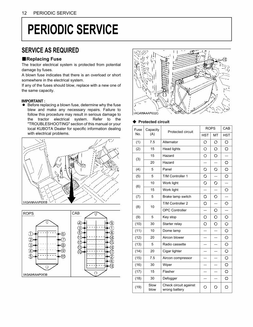
SERVICE AS REQUIREDBReplacing FuseThe tractor electrical system is protected from potentialdamage by fuses.A blown fuse indicates that there is an overload or shortsomewhere in the electrical system.If any of the fuses should blow, replace with a new one ofthe same capacity.A Before replacing a blown fuse, determine why the fuseblew and make any necessary repairs. Failure tofollow this procedure may result in serious damage tothe tractor electrical system. Refer to the"TROUBLESHOOTING" section of this manual or yourlocal KUBOTA Dealer for specific information dealingwith electrical problems.
C Protected circuit
FuseNo.
Capacity(A) Protected circuit
ROPS CAB
HST MT HST
(1) 7.5 Alternator
(2) 15 Head lights
(3)15 Hazard ---
20 Hazard --- ---
(4) 5 Panel
(5) 5 T/M Controller 1 ---
(6)10 Work light ---
15 Work light --- ---
(7) 5 Brake lamp switch ---
(8) 10T/M Controller 2 ---
OPC Controller --- ---
(9) 5 Key stop
(10) 30 Starter relay
(11) 10 Dome lamp --- ---
(12) 20 Aircon blower --- ---
(13) 5 Radio cassette --- ---
(14) 20 Cigar lighter --- ---
(15) 7.5 Aircon compressor --- ---
(16) 30 Wiper --- ---
(17) 15 Flasher --- ---
(18) 30 Defogger --- ---
(19) Slow blow
Check circuit against wrong battery
13PERIODIC SERVICE
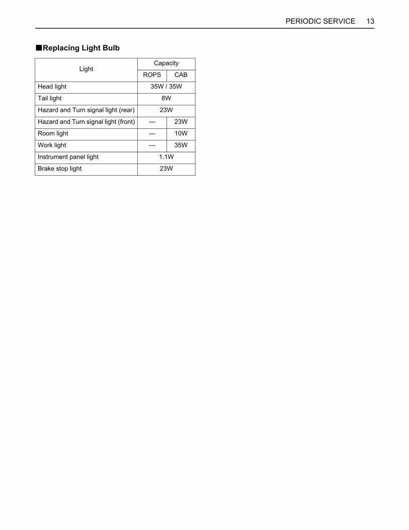
BReplacing Light Bulb
LightCapacity
ROPS CAB
Head light 35W / 35W
Tail light 8W
Hazard and Turn signal light (rear) 23W
Hazard and Turn signal light (front) --- 23W
Room light --- 10W
Work light --- 35W
Instrument panel light 1.1W
Brake stop light 23W