operator's manual - kubota tractor · pdf fileread operator's manual gasoline fuel...
TRANSCRIPT

Z122E-
AU·Z121S-
AU·Z125E-
AU·Z125S-
AU
READ AND SAVE THIS MANUAL
OPERATOR'S MANUAL
MODELS Z122E-AU Z121S-AU Z125E-AU Z125S-AU
1BDABDYAP0010
PRINTED IN U.S.A. © KUBOTA Corporation 2014
English (AUS)Code No. K3014-7123-1AS . B . 1 - 1 . - . AK
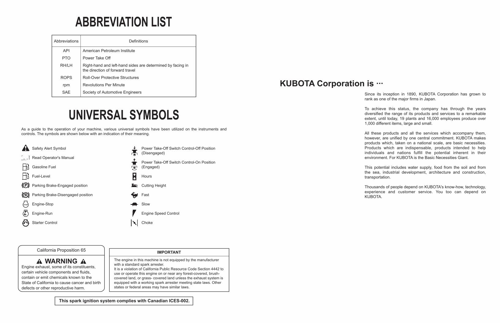
KUBOTA Corporation is ···Since its inception in 1890, KUBOTA Corporation has grown to rank as one of the major firms in Japan.
To achieve this status, the company has through the years diversified the range of its products and services to a remarkable extent, until today, 19 plants and 16,000 employees produce over 1,000 different items, large and small.
All these products and all the services which accompany them, however, are unified by one central commitment. KUBOTA makes products which, taken on a national scale, are basic necessities. Products which are indispensable, products intended to help individuals and nations fulfill the potential inherent in their environment. For KUBOTA is the Basic Necessities Giant.
This potential includes water supply, food from the soil and from the sea, industrial development, architecture and construction, transportation.
Thousands of people depend on KUBOTA's know-how, technology, experience and customer service. You too can depend on KUBOTA.
Abbreviations Definitions
ABBREVIATION LIST
API
PTO
RH/LH
ROPS
rpm
SAE
American Petroleum Institute
Power Take Off
Right-hand and left-hand sides are determined by facing in the direction of forward travel
Roll-Over Protective Structures
Revolutions Per Minute
Society of Automotive Engineers
UNIVERSAL SYMBOLSAs a guide to the operation of your machine, various universal symbols have been utilized on the instruments and controls. The symbols are shown below with an indication of their meaning.
Safety Alert Symbol
Read Operator's Manual
Gasoline Fuel
Fuel-Level
Parking Brake-Engaged position
Parking Brake-Disengaged position
Engine-Stop
Engine-Run
Starter Control
Power Take-Off Switch Control-Off Position(Disengaged)
Power Take-Off Switch Control-On Position(Engaged)
Hours
Cutting Height
Fast
Slow
Engine Speed Control
Choke
This spark ignition system complies with Canadian ICES-002.
California Proposition 65
WARNING Engine exhaust, some of its constituents, certain vehicle components and fluids, contain or emit chemicals known to the State of California to cause cancer and birth defects or other reproductive harm.
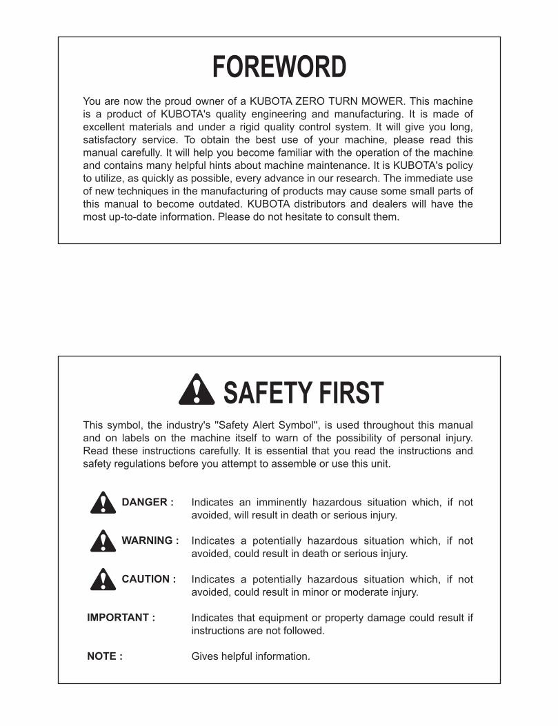
FOREWORD
3SAFETY FIRST
IMPORTANT :
NOTE :
3 DANGER :
3 WARNING :
3 CAUTION :
Indicates an imminently hazardous situation which, if not avoided, will result in death or serious injury.
Indicates a potentially hazardous situation which, if not avoided, could result in death or serious injury.
Indicates a potentially hazardous situation which, if not avoided, could result in minor or moderate injury.
Indicates that equipment or property damage could result if instructions are not followed.
Gives helpful information.
You are now the proud owner of a KUBOTA ZERO TURN MOWER. This machine is a product of KUBOTA's quality engineering and manufacturing. It is made of excellent materials and under a rigid quality control system. It will give you long, satisfactory service. To obtain the best use of your machine, please read this manual carefully. It will help you become familiar with the operation of the machine and contains many helpful hints about machine maintenance. It is KUBOTA's policy to utilize, as quickly as possible, every advance in our research. The immediate use of new techniques in the manufacturing of products may cause some small parts of this manual to become outdated. KUBOTA distributors and dealers will have the most up-to-date information. Please do not hesitate to consult them.
This symbol, the industry's ''Safety Alert Symbol'', is used throughout this manual and on labels on the machine itself to warn of the possibility of personal injury. Read these instructions carefully. It is essential that you read the instructions and safety regulations before you attempt to assemble or use this unit.

CONTENTS
SAFE OPERATION ............................................................................................ -1SERVICING OF MACHINE ......................................................................................... 1
SPECIFICATIONS....................................................................................................... 3
IMPLEMENT LIMITATIONS ........................................................................................ 5
INSTRUMENT PANEL AND CONTROLS................................................................... 6
MOWER MOUNTING.................................................................................................. 8MOUNTING THE MOWER DECK ........................................................................... 8ADJUSTING THE MOWER ..................................................................................... 8DISMOUNTING THE MOWER DECK ..................................................................... 8
OPERATING THE ENGINE......................................................................................... 9MOUNT AND DISMOUNT MACHINE SAFELY....................................................... 9STARTING THE ENGINE........................................................................................ 9
Throttle Lever..................................................................................................................11Key Switch ......................................................................................................................11
CHECK DURING OPERATING ............................................................................. 12Immediately Stop the Engine if: ......................................................................................12Fuel Gauge.....................................................................................................................12Hour Meter......................................................................................................................12
COLD WEATHER STARTING............................................................................... 12WARMING UP ....................................................................................................... 13
Warm-up and Transmission Oil in the Low Temperature Range....................................13JUMP STARTING .................................................................................................. 13STOPPING THE ENGINE...................................................................................... 14
OPERATING THE MACHINE.................................................................................... 15OPERATING NEW MACHINE............................................................................... 15
Changing Lubricating Oil for New Machines...................................................................15Engine Break-in ..............................................................................................................15Machine Break-in............................................................................................................15
STARTING............................................................................................................. 16Operator's Seat...............................................................................................................16Seat Belt .........................................................................................................................16Light Switch ....................................................................................................................16Mower Lift Pedal .............................................................................................................17Throttle Lever..................................................................................................................17Parking Brake Lever .......................................................................................................17Motion Control Lever ......................................................................................................18
STOPPING............................................................................................................. 20PARKING............................................................................................................... 20TRANSPORTING................................................................................................... 21
Hydrostatic Transaxle Bypass Rods...............................................................................21
OPERATING THE MOWER ...................................................................................... 22MAKING THE MOST OF YOUR MOWER............................................................. 22
CONTENTS
ADJUSTING CUTTING HEIGHT ........................................................................... 22OPERATING MOWER........................................................................................... 23
PTO Switch.....................................................................................................................23Starting ...........................................................................................................................24
TIRES AND WHEELS ............................................................................................... 25TIRES..................................................................................................................... 25
Inflation Pressure............................................................................................................25WHEELS................................................................................................................ 25
Remove and Install Front Caster Wheels .......................................................................26
MAINTENANCE......................................................................................................... 27SERVICE INTERVALS .......................................................................................... 27LUBRICANTS AND FUEL...................................................................................... 30
PERIODIC SERVICE................................................................................................. 31HOW TO RAISE THE OPERATOR'S SEAT.......................................................... 31DAILY CHECK ....................................................................................................... 32
Checking Engine Oil Level..............................................................................................32Checking Amount of Fuel and Refueling ........................................................................33Checking and Cleaning Air Intake Screen......................................................................34Checking Tire Pressure ..................................................................................................34Inflation Pressure............................................................................................................34Checking Transaxle Fluid Level......................................................................................35Checking Movable Parts.................................................................................................35
EVERY 25 HOURS................................................................................................ 36Cleaning Precleaner Element (Except Z125E) ...............................................................36Cleaning Air Cleaner Element (Z122E, Z125E)..............................................................37
EVERY 50 HOURS................................................................................................ 39Checking Engine Start System.......................................................................................39Checking OPC System...................................................................................................40Changing Engine Oil (Z122E, Z125E) ............................................................................40Replacing Engine Oil Filter (Z122E, Z125E)...................................................................41Checking Muffler and Spark Arrester (if equipped).........................................................42
EVERY 100 HOURS.............................................................................................. 43Changing Engine Oil (Z121S, Z125S) ............................................................................43Replacing Precleaner Element (Except Z125E) .............................................................43Replacing Air Cleaner Element (Z122E, Z125E) ............................................................43Replacing Air Cleaner Element (Z121S, Z125S) ............................................................44Cleaning Engine Shroud.................................................................................................44Checking Spark Plug ......................................................................................................45Checking Fuel Lines .......................................................................................................46Battery Condition ............................................................................................................48Adjusting Throttle Cable .................................................................................................49Replacing Engine Oil Filter (Z121S, Z125S)...................................................................50
EVERY 200 HOURS.............................................................................................. 51Checking Hydraulic Hose ...............................................................................................51
EVERY 400 HOURS.............................................................................................. 52Replacing Transaxle Oil Filter Cartridge.........................................................................52Changing Transaxle Fluid...............................................................................................53
EVERY 500 HOURS.............................................................................................. 54Electric Clutch Adjustment..............................................................................................54

CONTENTS
Checking Engine Valve Clearance (Z121S, Z125S).......................................................54EVERY AFTER 500 HOURS ................................................................................. 55
Cleaning Combustion Chamber......................................................................................55EVERY 1 YEAR ..................................................................................................... 55
Replacing Precleaner Element (Except Z125E) .............................................................55Replacing Air Cleaner Element (Z122E, Z125E) ............................................................55Replacing Air Cleaner Element (Z121S, Z125S) ............................................................55Changing Engine Oil (Z122E, Z125E) ............................................................................55Replacing Engine Oil Filter (Z122E, Z125E)...................................................................55Replacing Fuel Filter (Z122E, Z125E) ............................................................................55Checking Muffler and Spark Arrester (if equipped).........................................................55Replacing Spark Plug .....................................................................................................55Checking Engine Valve Clearance (Z122E, Z125E).......................................................55
EVERY 2 YEARS................................................................................................... 55Replacing Hydraulic Hose ..............................................................................................55Replacing Fuel Lines ......................................................................................................55Replacing Engine Breather Hose ...................................................................................55
SERVICE AS REQUIRED...................................................................................... 56Replacing Fuses.............................................................................................................56Checking and Replacing Blade.......................................................................................56Mower Belt Replacement................................................................................................58
ADJUSTMENT........................................................................................................... 59MOTION CONTROL LEVER ................................................................................. 59
HST NEUTRAL...............................................................................................................59MAXIMUM SPEED (FORWARD) ...................................................................................60MOTION CONTROL LEVER ALIGNMENT....................................................................60
MOWER DECK LEVEL.......................................................................................... 61ANTI-SCALP ROLLERS.................................................................................................61LEVEL MOWER DECK (Side-to-Side) ...........................................................................62LEVEL MOWER DECK (Front-to-Rear) .........................................................................63
GENERAL TORQUE SPECIFICATION................................................................. 64TIGHTENING TORQUE CHART ........................................................................... 65
STORAGE ................................................................................................................. 66
TROUBLESHOOTING............................................................................................... 67ENGINE TROUBLESHOOTING ............................................................................ 67BATTERY TROUBLESHOOTING ......................................................................... 69MACHINE TROUBLESHOOTING ......................................................................... 69MOWER TROUBLESHOOTING............................................................................ 70
INDEX........................................................................................................................ 72

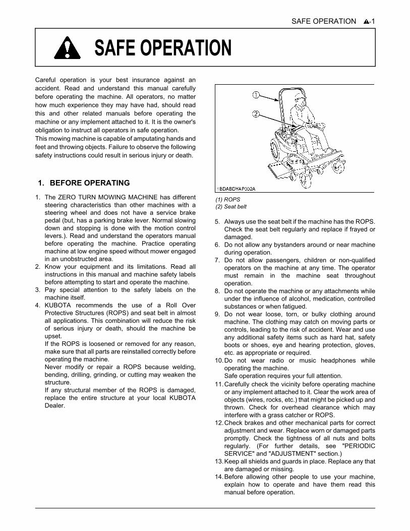
-1SAFE OPERATION
SAFE OPERATION
Careful operation is your best insurance against anaccident. Read and understand this manual carefullybefore operating the machine. All operators, no matterhow much experience they may have had, should readthis and other related manuals before operating themachine or any implement attached to it. It is the owner'sobligation to instruct all operators in safe operation.This mowing machine is capable of amputating hands andfeet and throwing objects. Failure to observe the followingsafety instructions could result in serious injury or death.1. The ZERO TURN MOWING MACHINE has differentsteering characteristics than other machines with asteering wheel and does not have a service brakepedal (but, has a parking brake lever. Normal slowingdown and stopping is done with the motion controllevers.). Read and understand the operators manualbefore operating the machine. Practice operatingmachine at low engine speed without mower engagedin an unobstructed area.
2. Know your equipment and its limitations. Read allinstructions in this manual and machine safety labelsbefore attempting to start and operate the machine.
3. Pay special attention to the safety labels on themachine itself.
4. KUBOTA recommends the use of a Roll OverProtective Structures (ROPS) and seat belt in almostall applications. This combination will reduce the riskof serious injury or death, should the machine beupset.If the ROPS is loosened or removed for any reason,make sure that all parts are reinstalled correctly beforeoperating the machine.Never modify or repair a ROPS because welding,bending, drilling, grinding, or cutting may weaken thestructure.If any structural member of the ROPS is damaged,replace the entire structure at your local KUBOTADealer.
5. Always use the seat belt if the machine has the ROPS.Check the seat belt regularly and replace if frayed ordamaged.
6. Do not allow any bystanders around or near machineduring operation.
7. Do not allow passengers, children or non-qualifiedoperators on the machine at any time. The operatormust remain in the machine seat throughoutoperation.
8. Do not operate the machine or any attachments whileunder the influence of alcohol, medication, controlledsubstances or when fatigued.
9. Do not wear loose, torn, or bulky clothing aroundmachine. The clothing may catch on moving parts orcontrols, leading to the risk of accident. Wear and useany additional safety items such as hard hat, safetyboots or shoes, eye and hearing protection, gloves,etc. as appropriate or required.
10.Do not wear radio or music headphones whileoperating the machine.Safe operation requires your full attention.
11.Carefully check the vicinity before operating machineor any implement attached to it. Clear the work area ofobjects (wires, rocks, etc.) that might be picked up andthrown. Check for overhead clearance which mayinterfere with a grass catcher or ROPS.
12.Check brakes and other mechanical parts for correctadjustment and wear. Replace worn or damaged partspromptly. Check the tightness of all nuts and boltsregularly. (For further details, see "PERIODICSERVICE" and "ADJUSTMENT" section.)
13.Keep all shields and guards in place. Replace any thatare damaged or missing.
14.Before allowing other people to use your machine,explain how to operate and have them read thismanual before operation.
1. BEFORE OPERATING
(1) ROPS(2) Seat belt
SAFE OPERATION-2
15. In addition to the design and configuration ofequipment, hazard control and accident preventionare dependent upon the awareness, concern andprudence of personnel involved in the operation,transport and maintenance of the equipment.
16.Keep the machine and attachments in good operatingcondition and keep safety devices in place and inproper working condition.
17.Do not modify the machine. Unauthorized modificationmay affect the function of the machine, which mayresult in personal injury.
18.Use only implements approved by KUBOTA. Useproper ballast to front or rear of machine to reduce therisk of upsets. Follow the "Safe Operation"procedures, specified in the manuals with equipment.
19.Keep your machine clean. Accumulations of dirt,grease, and trash can contribute to fires and lead topersonal injury.
20.The exhaust gas from the muffler is very hot. Toprevent fire, do not expose dry grass, mowed grass, oiland any other combustible materials to exhaust gas.Use a spark arrester where required. Also keep theengine and muffler clean all the time.
C Starting1. Always sit in the operator's seat when starting engine
or operating levers or controls.2. Before starting the engine make sure that the motion
control levers are in neutral lock, the parking brake isapplied, and Power Take Off (PTO) is disengaged(OFF).
3. Do not start engine by shorting across starterterminals. The machine may start in gear and move ifnormal starting circuitry is bypassed.
4. Do not operate or idle engine in a non-ventilated area.Carbon monoxide gas is colorless, odorless, anddeadly.
5. Do not start engine while tilting deck.6. Check before each use that operator presence
controls are functioning correctly. Test safety systems.(See "Checking Engine Start System" and "CheckingOPC System" in "EVERY 50 HOURS" in "PERIODICSERVICE" section.)Do not operate unless they are functioning correctly.
C Working1. Do not turn sharply when driving at high speed.2. To avoid tip over, slow down when turning on uneven
terrain or before stopping.3. Do not operate near ditches, holes, embankments, or
other terrain, which may collapse under the machineweight. The risk of machine tip over increases whenthe ground is loose or wet.
4. Park the machine on a firm and level surface.
5. Watch where you are going at all times. Watch for andavoid obstacles. Be alert at curbs, near trees, andother obstructions and hidden hazards.
6. Know what is behind you before backing up. Look tothe rear before and when backing. Do not mow whilein reverse unless absolutely necessary and make surethe area immediately behind you is clear ofobstructions or holes and small children. Use extracaution when machine is equipped with GrassCatcher. Your view to the rear is restricted.
7. When working in groups, always let others know whatyou are doing ahead of time.
8. Do not drive machine on streets or highways. Watchfor traffic when you cross roads or operate near roads.
9. Be aware of the mower discharge direction and do notpoint it at anyone.
10.When using any attachments, never direct dischargematerial toward bystanders. Do not allow anyone nearthe attachments while in operation.Do not mow when bystanders are present in themowing area.
11.To reduce fire hazards, keep the engine exhaust areafree of grass or leaves.
12.Be sure rotating blades and engine are stopped andthe key is removed before placing hands or feet nearblades and cleaning blockages or unclogging chute.
13.Shut the engine off and wait for all movement to stopbefore removing grass catcher or unclogging chute.
14.Maintain all screens to avoid overheating conditions.15.Always inspect the mower for damage after striking a
foreign object. Repair or replace any damaged partsbefore restarting.
16.Operate during daylight or in bright artificial light.
C ChildrenTragic accidents can occur if the operator is not alert tothe presence of children. Children are attracted to themachine and mowing activity.Never assume that children will remain where you lastsaw them.1. Keep children out of the mowing area and under the
watchful care of another responsible adult.2. Be alert and turn machine off if children enter the area.3. Before and when backing, look behind and down for
small children.4. Never carry children. There is no safe place for them
to ride. They may fall off and be seriously injured orinterfere with safe machine operation.
5. Never allow children to operate the machine, evenunder adult supervision.
6. Use extra care when approaching blind corners,shrubs, trees, or other obstructions that might hidechildren from sight.
7. Do not mow in reverse unless it is absolutelynecessary and make sure area to the rear is clear ofchildren before doing so.
2. OPERATING

-3SAFE OPERATION
C Operators, age 60 years and aboveData indicates that operators, age 60 years and above,are involved in a large percentage of machine-relatedinjuries. These operators should evaluate their ability tooperate the machine safely enough to protect themselvesand others from serious injury.
C Operation on slopesSlopes are a major factor related to loss-of-control and tip-over accidents, which can result in severe injury or death.All slopes require extra caution.If you cannot back up the slope or if you feel uneasy on it,do not mow it.If the engine stops when operating on a slope apply theparking brake immediately to prevent machine run away.
DO1. To avoid tip over, operate across the slopes not up and
down. Stay off hills and slopes too steep for safeoperation.
2. Remove obstacles such as rocks, tree limbs, etc.3. Stay alert for holes in the terrain and other hidden
hazards. Keep away from drop-offs. Uneven terraincould overturn the machine. Tall grass can hideobstacles.
4. Follow the manufacturer's recommendations for wheelweight or counterweights to improve stability.
5. Keep all movement on the slopes slow and gradual.Do not make sudden changes in speed or direction.
6. Avoid starting or stopping on a slope. If tires losetraction, disengage PTO and proceed slowly straightdown the slope.
7. Reduce speed and exercise extreme caution onslopes and in sharp turns to prevent tip-over or loss ofcontrol.
8. Use special caution when changing direction onslopes. Slow down, and use extra caution whenchanging direction on a slope.
DO NOT1. Do not turn on slopes unless necessary. If necessary,
turn uphill slowly and gradually.2. Do not mow near drop-offs, ditches, or embankments.
The mower could suddenly turn over if a wheel is overthe edge of cliff or ditch, or if an edge caves in.
3. Do not mow on wet grass. Reduced traction couldcause sliding and loss of control.
4. Do not try to stabilize the machine by putting your footon the ground.
5. Do not use grass catcher on steep slopes.6. Do not start or stop suddenly when going uphill or
downhill. Avoid sudden start and stops on slopes.7. Never "freewheel". Do not let the machine travel
downhill with motion control levers at neutral lockposition or in neutral.
8. Do not operate machine without the mower deckinstalled.
C Stopping1. Park the machine on level ground.2. Make sure that the machine and all attachments have
come to a complete stop before dismounting.3. Before dismounting, apply parking brake, place the
motion control levers in their neutral lock positions,disengage the PTO, lower all attachments to theground, turn off the engine, and remove the key.
4. Do not park the machine on dry grass or leaves.
1. Disengage power to attachment(s) when transportingor not in use.
2. Do not tow this machine. Use a suitable truck or trailerwhen transporting on public roads.
3. Use extra care when loading or unloading the machineinto a trailer or truck.
4. This machine is not allowed to be used on publicroads.
C Servicing1. Before servicing, park the machine on a firm, level
surface and apply the parking brake. Remove the keyto prevent accidental start-up.
2. Allow the machine time to cool before touching theengine, muffler, etc.
3. Always stop the engine before refueling. Avoid spillsand overfilling. Wipe up spilled fuel immediately.
4. Use extra care in handling gasoline fuels. They areflammable.(1) Use only an approved container.(2) Do not remove fuel cap or refuel with the engine
running. Allow engine to cool before refueling. Donot smoke while refueling or when standing nearfuel.
(3) Do not refuel the machine indoors and alwaysclean up spilled fuel or oil.
3. TRANSPORTING
4. SERVICING AND STORAGE
(1) Fuel tank cap
SAFE OPERATION-4
(4) Do not store the machine or fuel container insidewhere there is an open flame, such as in a waterheater.
5. Do not smoke when working around battery or whenrefueling. Keep all sparks and flames away frombattery and fuel tank.A battery, especially when charging, will give offhydrogen and oxygen gases, which can explode andcause serious personal injury.
6. Before "jump starting" a dead battery, read and followall the instructions.
7. Disconnect the battery's ground cable before workingon or near electric components.
8. Do not use or charge the refillable type battery if thefluid level is below the LOWER (lower limit level) mark.Otherwise, the battery component parts mayprematurely deteriorate, which may shorten thebattery's service life or cause an explosion. Check thefluid level regularly and add distilled water as requiredso that the fluid level is between the UPPER andLOWER levels.
9. Keep first aid kit and fire extinguisher handy at alltimes.
10.Do not attempt to mount a tire on a rim unless qualifiedto do so and all proper safety precautions are followed.
11.Always maintain the correct tire inflation pressure. Donot inflate tires above the recommended pressureshown in the Operator's Manual.
12.Provide adequate support when changing wheels.13.Make sure that wheel nuts and bolts have been
tightened to the specified torque.14.Do not make adjustments or repairs with the engine
running.15.Keep machine free of grass, leaves, or other debris
build-up.16.Do not change the engine governor setting or
overspeed the engine.17.Do not run a machine inside a closed area.18.Mower blades are sharp and can cut your hands. Wrap
the blade(s) or wear gloves, and use extra cautionwhen servicing them.
19.Keep nuts and bolts, especially blade attachmentbolts, tight and keep equipment in good condition.
20.Never tamper with safety devices. Check theiroperation for proper function regularly.
21.Waste products such as used oil, fuel, coolant, brakefluid, and batteries, can harm the environment, people,pets and wildlife. Please dispose of properly.
22.Do not use beverage containers for waste fluids orother products. Someone, particularly children, maydrink them by mistake.
23.Securely support machine or any machine elementswith stands or suitable blocking before workingunderneath. For your safety do not rely onhydraulically supported devices, they may leak down,suddenly drop or be accidently lowered.
24.See your local Recycling Center or KUBOTA Dealer tolearn how to recycle or get rid of waste products.A A Material Safety Data Sheet (MSDS) provides
specific details on chemical products; physical andhealth hazards, safety procedures, and emergencyresponse techniques. The seller of the chemicalproducts used with your machine is responsible forproviding the MSDS for that product upon request.
C Storage1. Keep the machine and supply of fuel in locked storage
and remove the ignition key to prevent children orothers from playing or tampering with them.
2. To avoid sparks from an accidental short circuit,always disconnect the battery's ground cable (-) firstand reconnect it last.
3. To avoid the danger of exhaust fume poisoning, do notoperate the engine in a closed building withoutadequate ventilation.
4. To reduce fire hazards, clean the machine thoroughlybefore storage. Dry grass and leaves around theengine and muffler may ignite.
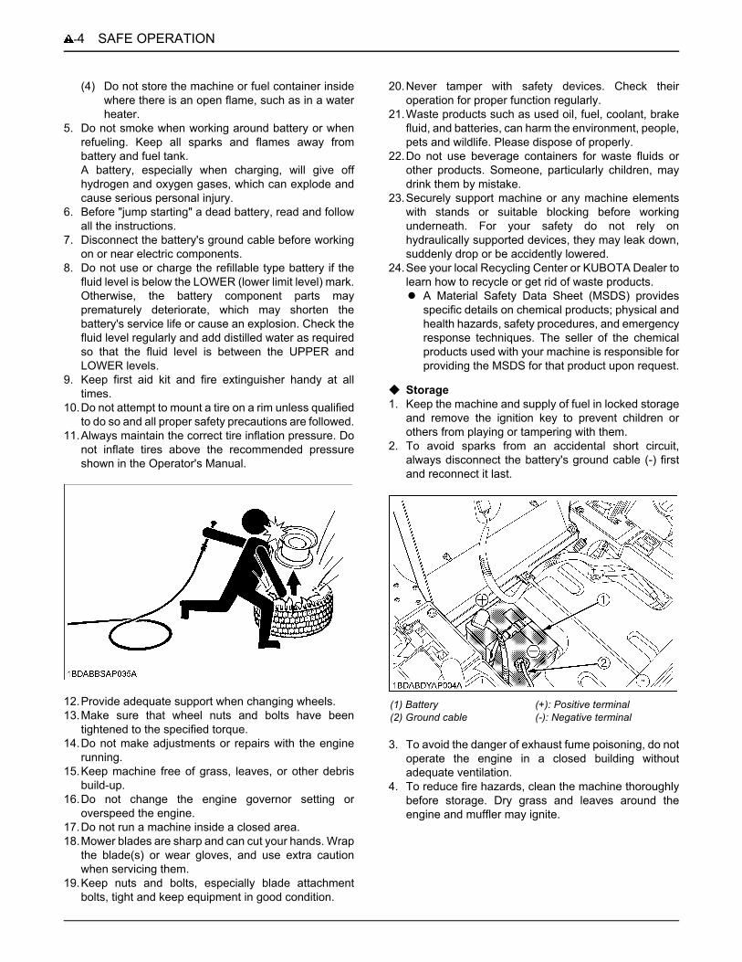
(1) Battery(2) Ground cable
(+): Positive terminal(-): Negative terminal

-5SAFE OPERATION
5. DANGER, WARNING AND CAUTION LABELS
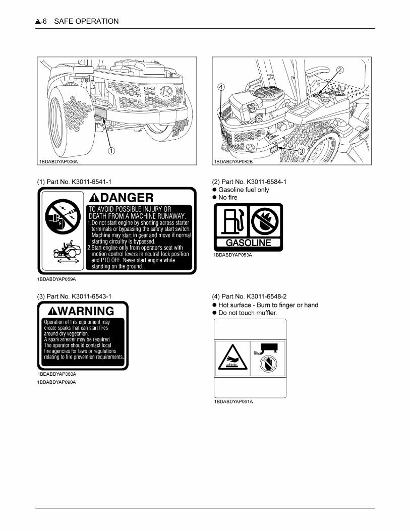
SAFE OPERATION-6
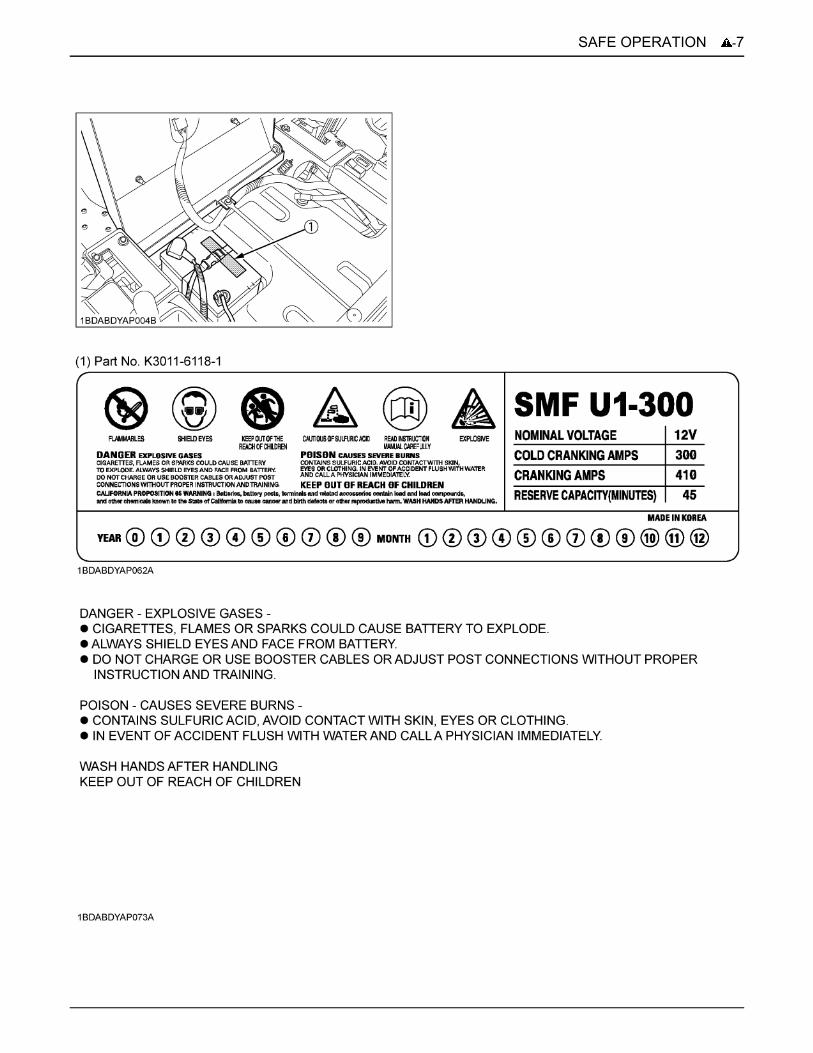
-7SAFE OPERATION
SAFE OPERATION-8
1. Keep danger, warning and caution labels clean and free from obstructing material.2. Clean danger, warning and caution labels with soap and water, and dry with a soft cloth.3. Replace damaged or missing danger, warning and caution labels with new labels from your local KUBOTA Dealer.4. If a component with danger, warning and caution label(s) affixed is replaced with new part, make sure new label(s) is
(are) attached in the same location(s) as the replaced component.5. Mount new danger, warning and caution labels by applying on a clean dry surface and pressing any bubbles to outside
edge.
6. CARE OF DANGER, WARNING, AND CAUTION LABELS
1SERVICING OF MACHINE
SERVICING OF MACHINE
After reading this manual thoroughly, you will find that youcan do some of the regular maintenance yourself. Yourdealer is interested in helping you get the bestperformance from your new machine and wants to helpyou get the most value from it. When in need of parts ormajor service, be sure to see your KUBOTA Dealer. Whenin need of parts, be prepared to give your dealer the serialnumber of the machine, ROPS, engine and mower.Locate the serial numbers now and record them in thespace provided.
C WarrantyThis machine is warranted under the Kubota LimitedExpress warranty, a copy of which may be obtained fromyour selling dealer. No warranty shall, however, apply ifthe machine has not been handled according to theinstruction given in the Operator's Manual even it is withinthe warranty period.
C Scrapping the machine and its procedureTo put the machine out of service, correctly follow thelocal rules and regulations of the country or territory whereyou scrap it. If you have questions, consult your localKUBOTA Dealer.
[Z122E]
[Z125E]
Type Serial No.
Machine
ROPS
Engine
Mower
Date of Purchase
Name of Dealer
(To be filled in by purchaser)
(1) Machine identification plate(2) Machine serial No.
(1) Engine serial No.
(1) Engine serial No.
SERVICING OF MACHINE2
[Z121S, Z125S]
(1) Engine serial No.
(1) Mower identification plate(2) Mower serial No.
(1) ROPS serial No.
3SPECIFICATIONS
SPECIFICATIONS
Model Z122E-AU Z121S-AU Z125E-AU Z125S-AUEngine
Model GH731V-1 GH736V GH733V-1 GH750V
Max. engine power (Gross) kW (HP) 16.4 (22) *1*2 15.7 (21) *1*3 18.6 (25) *1*2 18.6 (25) *1*3
Type Air-cooled gasoline engine
Number of cylinders 2 (V-Twin)
Bore and stroke mm (in.) 79 x 73(3.11 x 2.87)
83 x 67(3.27 x 2.64)
79 x 73(3.11 x 2.87)
83 x 69(3.27 x 2.72)
Total displacement cm (cu. in.) 724 (44) 725 (44) 724 (44) 747 (46)
Rated revolution rpm 3600
Fuel Unleaded gasoline
Starter Electric
Lubrication Full pressure lubrication
Cooling Air cooled
Battery U1 (12 V, RC: 45 min, CCA: 300, CA: 410)
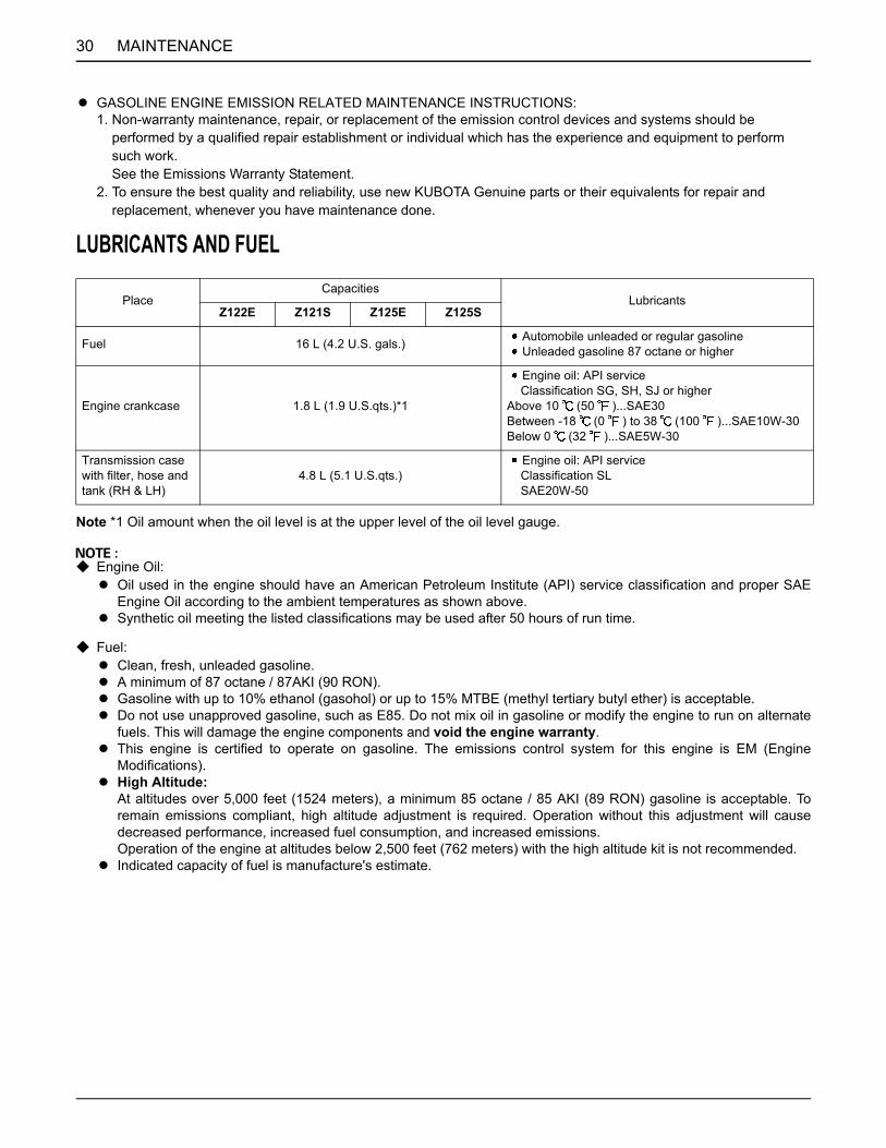
Capacities
Fuel tank L (U.S.gals.) 16 (4.2)
Engine crankcase(with filter) L (U.S.qts.) 1.8 (1.9)
Transmission case including Rear axle gear case
L (U.S.qts.) 4.8 (5.1) (*4)
Dimensions
Overall length mm (in.) 1940 (76.4)
Overall widthw/o mower deck mm (in.) 1207 (47.5)
Overallheight With ROPS mm (in.) 1652 (65.0)
Wheelbase mm (in.) 1155 (45.5)
Min. ground clearance mm (in.) 123 (4.84)W/48"
123 (4.84)W/54"
TreadFront mm (in.) 796 (31.3)
Rear mm (in.) 954 (37.6)
Weight (W/MOWER DECK) kg (lbs.) 330 (728) with 48" 340 (750) with 48" 340 (750) with 54" 350 (772) with 54"
Traveling system
TiresFront 11 x 4 - 5 (4PR) Smooth
Rear 22 x 10 - 14 (4PR) Turf
Traveling speeds
Forward mph (km/h) 0 to 8.0 (0 to 12.9)
Reverse mph (km/h) 0 to 4.0 (0 to 6.4)
Steering 2 - Hand levers
Transmission 2 - HST w / Gear
Parking brake Hand lever applied, released
Min. turning radius mm (in.) 0 (0)
4 SPECIFICATIONS
*1: Engine Max rpm
PTODrive system Belt
Clutch type Electric
(Specifications and design subject to change without notice)NOTE:*1: Manufacturer's estimate*2: The gross power rating for individual gas engine models is labeled in accordance with SAE (Society of Automotive Engineers) code J1940 (Small Engine Power & Torque Rating Procedure), and rating performance has been obtained and corrected in accordance with SAE J1995 (Revision 2002-05). Torque values are derived at 3060 RPM; horsepower values are derived at 3600 RPM. Actual gross engine power will be lower and is affected by, among other things, ambient operating conditions and engine-to-engine variability. Given both the wide array of products on which engines are placed and the variety of environmental issues applicable to operating the equipment, the gas engine will not develop the rated gross power when used in a given piece of power equipment (actual "on- site" or net power). This difference is due to a variety of factors including, but not limited to, accessories (air cleaner, exhaust, charging, cooling, carburetor, fuel pump, etc.), application limitations, ambient operating conditions (temperature, humidity, altitude), and engine-to-engine variability. Due to manufacturing and capacity limitations, Briggs & Stratton may substitute an engine of higher rated power for this Series engine.*3: Horsepower ratings exceed Society of Automotive Engineers Small Engine Test Code J1940. Actual engine horsepower is lower and affected by, but not limited to, accessories (air cleaner, exhaust, charging, cooling, fuel pump, etc.), application, engine speed and ambient operating conditions (temperature, humidity, and altitude). Kohler reserves the right to change product specifications, design, and standard equipment without notice and without incurring obligation.*4: Oil amount when the oil level is at the upper level.
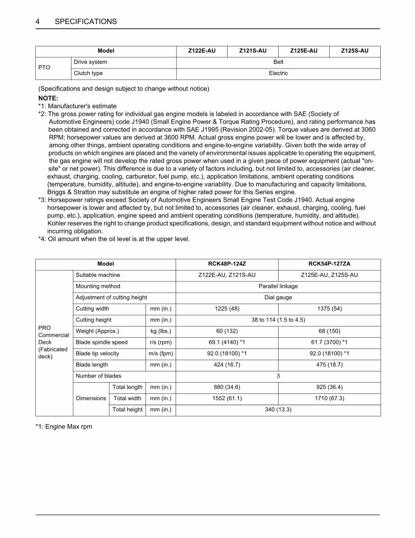
Model RCK48P-124Z RCK54P-127ZA
PRO Commercial Deck (Fabricated deck)
Suitable machine Z122E-AU, Z121S-AU Z125E-AU, Z125S-AU
Mounting method Parallel linkage
Adjustment of cutting height Dial gauge
Cutting width mm (in.) 1225 (48) 1375 (54)
Cutting height mm (in.) 38 to 114 (1.5 to 4.5)
Weight (Approx.) kg (lbs.) 60 (132) 68 (150)
Blade spindle speed r/s (rpm) 69.1 (4140) *1 61.7 (3700) *1
Blade tip velocity m/s (fpm) 92.0 (18100) *1 92.0 (18100) *1
Blade length mm (in.) 424 (16.7) 475 (18.7)
Number of blades 3
Dimensions
Total length mm (in.) 880 (34.6) 925 (36.4)
Total width mm (in.) 1552 (61.1) 1710 (67.3)
Total height mm (in.) 340 (13.3)
Model Z122E-AU Z121S-AU Z125E-AU Z125S-AU

5IMPLEMENT LIMITATIONS
IMPLEMENT LIMITATIONS
The KUBOTA Machine has been thoroughly tested for proper performance with implements sold or approved by KUBOTA.Use with implements which are not sold or approved by KUBOTA and which exceed the maximum specifications listedbelow, or which are otherwise unfit for use with the KUBOTA Machine may result in malfunctions or failures of the machine,damage to other property and injury to the operator or others. [Any malfunctions or failures of the machine resulting fromuse with improper implements are not covered by the warranty.]A Do not operate with trailer on incline greater than 10 .
Maximum loading weight Maximum total
weightTongue weight
WTowing capacity
WFront axleWf
Rear axleWr
Z122E, Z121S, Z125E, Z125S 98 kg (217 lbs.) 380 kg (837 lbs.) 478 kg (1054 lbs.) 34 kg (75 lbs.) 113 kg (250 lbs.)
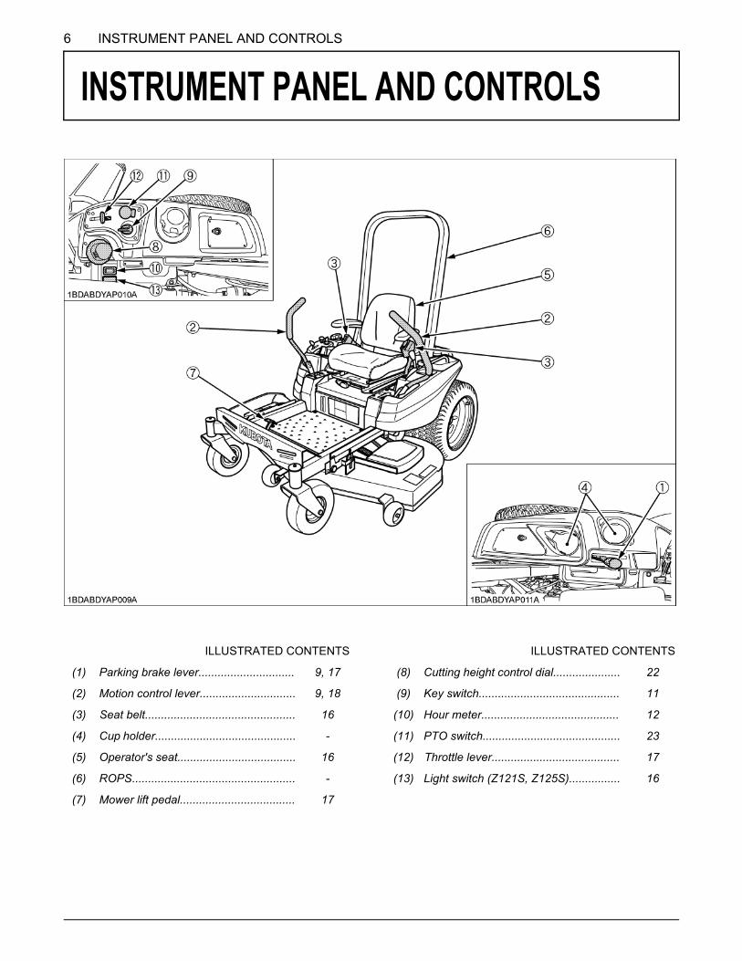
6 INSTRUMENT PANEL AND CONTROLS
INSTRUMENT PANEL AND CONTROLS
ILLUSTRATED CONTENTS ILLUSTRATED CONTENTS
(1) Parking brake lever.............................. 9, 17 (8) Cutting height control dial..................... 22
(2) Motion control lever.............................. 9, 18 (9) Key switch............................................ 11
(3) Seat belt............................................... 16 (10) Hour meter........................................... 12
(4) Cup holder............................................ - (11) PTO switch........................................... 23
(5) Operator's seat..................................... 16 (12) Throttle lever........................................ 17
(6) ROPS................................................... - (13) Light switch (Z121S, Z125S)................ 16
(7) Mower lift pedal.................................... 17
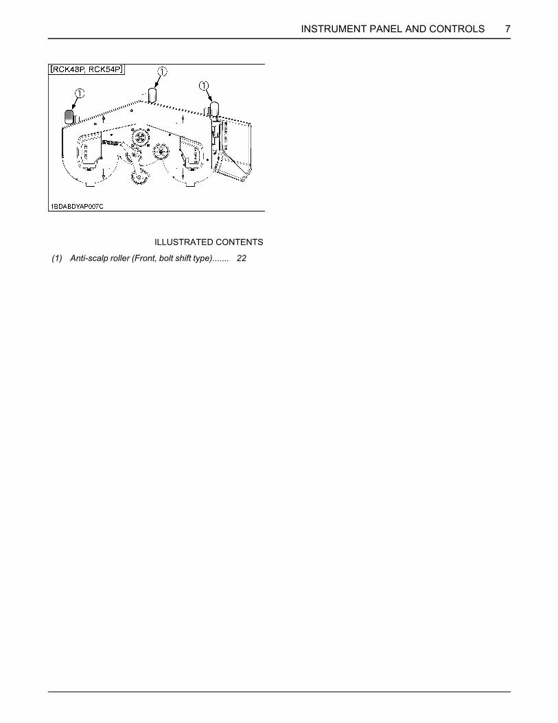
7INSTRUMENT PANEL AND CONTROLS
ILLUSTRATED CONTENTS
(1) Anti-scalp roller (Front, bolt shift type)....... 22
8 MOWER MOUNTING
MOWER MOUNTING
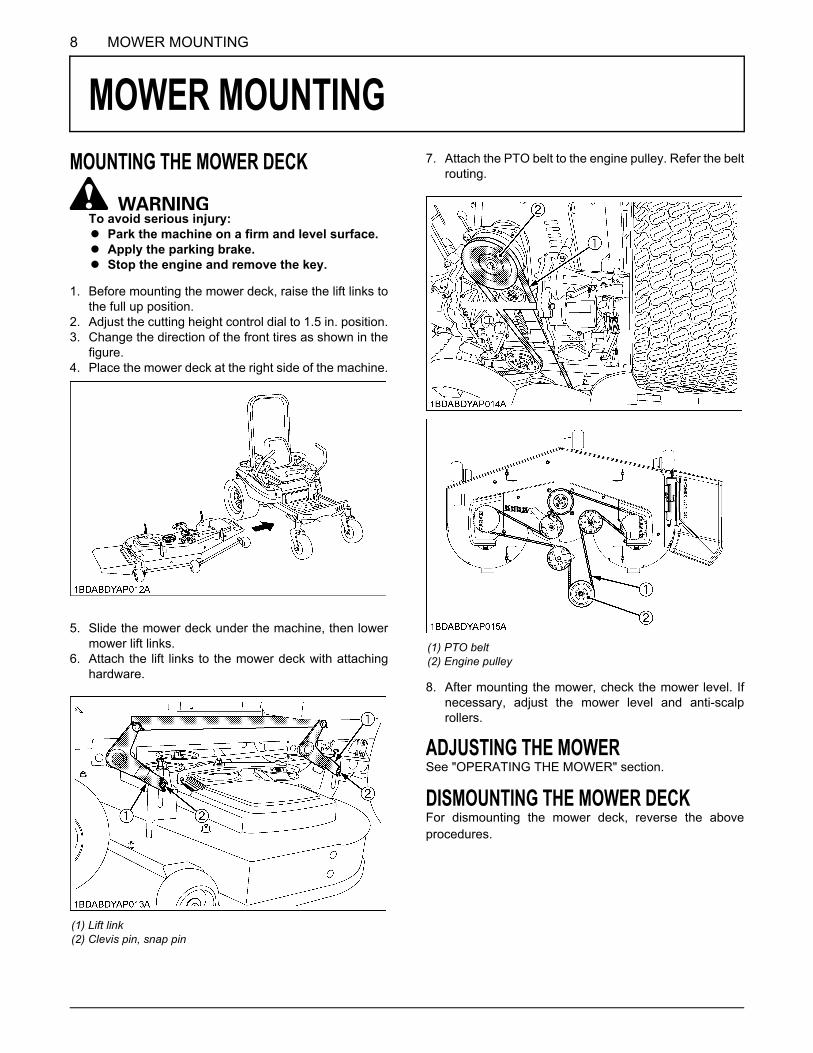
MOUNTING THE MOWER DECKTo avoid serious injury:A Park the machine on a firm and level surface.A Apply the parking brake.A Stop the engine and remove the key.
1. Before mounting the mower deck, raise the lift links tothe full up position.
2. Adjust the cutting height control dial to 1.5 in. position.3. Change the direction of the front tires as shown in the
figure.4. Place the mower deck at the right side of the machine.
5. Slide the mower deck under the machine, then lowermower lift links.
6. Attach the lift links to the mower deck with attachinghardware.
7. Attach the PTO belt to the engine pulley. Refer the beltrouting.
8. After mounting the mower, check the mower level. Ifnecessary, adjust the mower level and anti-scalprollers.
ADJUSTING THE MOWERSee "OPERATING THE MOWER" section.
DISMOUNTING THE MOWER DECKFor dismounting the mower deck, reverse the aboveprocedures.
(1) Lift link(2) Clevis pin, snap pin
(1) PTO belt(2) Engine pulley

9OPERATING THE ENGINE
OPERATING THE ENGINE
To avoid serious injury:A Read and understand "SAFE OPERATION" in
the front of this manual.A Read and understand the danger, warning and
caution labels located on the machine.A To avoid danger of exhaust fume poisoning, do
not operate the engine in a closed buildingwithout proper ventilation.
A Never start the engine while standing on theground. Start the engine only from operator'sseat.
MOUNT AND DISMOUNT MACHINE SAFELYDO NOT step on either side of the mower deck whenmounting and dismounting the machine. When mountingthe machine from either side, step over the mower deck.
STARTING THE ENGINE
To apply the parking brake:Place the parking brake lever in the "ENGAGED"position.
To release the parking brake:Place the parking brake lever in the "DISENGAGED"position.
1. Sit on the operator's seat.
2. Apply the parking brake.
(1) Parking brake lever "ENGAGED""DISENGAGED"

OPERATING THE ENGINE10
A If the engine is cold:Place the throttle lever to the "CHOKE" position.
A If the engine is warm:Place the throttle lever midway between the "SLOW"and the "FAST" positions.
3. Make sure that the PTO switch is in the "DISENGAGED" (OFF) position.
(1) PTO switch "ENGAGED" (ON)
"DISENGAGED" (OFF)
4. Place the motion control levers in the "NEUTRAL LOCK" position.
(1) Motion control lever (LH)(2) Motion control lever (RH)
(A) "NEUTRAL LOCK" Position(B) "NEUTRAL" Position (held by hands)(C) "FORWARD"(D) "REVERSE"
5. Set the throttle lever as follows.
(1) Throttle lever "FAST""SLOW""CHOKE"

11OPERATING THE ENGINE
A Because of the start interlocks, the engine can not bestarted except when the PTO switch is disengaged(OFF), the parking brake lever is applied, motioncontrol levers are in "NEUTRAL LOCK" position andthe operator is sitting on the seat.
BThrottle LeverPulling the throttle lever backward decreases the enginespeed and pushing it forward increases the engine speed.When the lever is pushed beyond the "FAST" position, thechoke is engaged.
[For a Cold Engine]Always place the throttle lever to the "CHOKE" position tostart the engine in cold conditions.
Gradually return the throttle lever to the usual positionafter the engine starts and warms up.
The engine/equipment may be operated during the warm-up period, but it may be necessary to leave the chokepartially on until the engine warms up.
[For a Warm Engine]Always place the throttle lever to the usual position afterthe engine starts.
BKey Switch
A Do not use starting fluid or ether.A To protect the battery and the starter, make sure that
the starter is not continuously turned for more than 10seconds at a time.If the engine does not start, allow 60 seconds cooldown period between starting attempts.
A If the starter does not turn the engine over, shut off thestarter immediately. Do not make further attempts tostart the engine until the condition is corrected. Do notjump start using another battery.Consult your local KUBOTA dealer.
A Do not turn the key switch to the "START" positionwhile the engine is running.
A When the temperature is below 0 (32 ), run theengine at medium speed to warm up the lubricant ofthe engine and the transmission for at least 10minutes. If the machine is operated before thelubricant is warm enough, the machine life will beshortened.
A Do not operate the machine under full load until it issufficiently warmed up 2 or 3 minutes for temperatureabove 0 (32 ).
A When the ambient temperature is less than -15(5 ), remove the battery from the machine and storeit somewhere warm until the next operation.
6. Insert the key into the key switch. Turn the key switch to the "START" position and release the key to the "ON" position when the engine starts.
OFF............ The position where the key can be inserted into or removed from the key switch. [When the key is turned to this position, the engine shuts off.]
ON.............. The engine keeps running.
START........ Apply the parking brake and turn the key switch to this position to start the engine.
: "OFF": "ON"
: "START"
7. Warm the engine by running at medium speed.

OPERATING THE ENGINE12
CHECK DURING OPERATINGWhile operating, make the following checks to see that allthe parts are functioning normally.
BImmediately Stop the Engine if:A The engine suddenly slows down or accelerates.A Unusual noises suddenly occur.A Exhaust fumes suddenly become discolored.
BFuel GaugeThe fuel gauge indicates the fuel level.
A Do not refuel over "F". Fill the tank only to the bottomof the filler neck in the fuel tank.
A Fill the fuel on a level ground.
BHour MeterThis meter gives readings for the number of hours theengine has been running.
COLD WEATHER STARTINGIf the ambient temperature is below 0 (32 ) and theengine is very cold, start it in the following manner:1. Place the throttle lever to the "CHOKE" position.2. Turn the key switch to the START (" ") position.
A Operate the starter 5 seconds.A If the engine does not start, wait 10 seconds.A Repeat this procedure until the engine starts.
3. When the engine starts, release the key to the "ON"(" ") position.
4. Place the throttle lever midway between the "SLOW"and the "FAST" positions.
(1) Fuel gauge (E) "EMPTY"(F) "FULL"
(1) Hour meter

13OPERATING THE ENGINE
WARMING UP
To avoid serious injury:A Be sure to apply the parking brake during
warm-up.
For 5 minutes after engine start-up, allow the engine towarm up without applying any load. This is to allow oil toreach every part of the engine. If load should be appliedto the engine without this warm-up period, problems maydevelop such as seizure, breakage or premature wearmay develop.
BWarm-up and Transmission Oil in the Low Temperature Range
Hydraulic oil serves as transmission oil. In cold weather,the oil may be cold with increased viscosity. This cancause delayed oil circulation or abnormally low hydraulicpressure for some time after engine start-up. This in turncan create problems with the hydraulic system.To prevent the above, observe the following instructions:Warm up the engine at about 50% of rated rpm accordingto the table below:
A Do not operate unless the engine is well warmed up. Ifoperation is attempted while the engine is still cold, thehydraulic mechanism will not function properly and itsservice life will be shortened.
A If noises are heard after the hydraulic control lever hasbeen activated and the implement is lifting, thehydraulic mechanism is not adjusted properly. Unlesscorrected, the unit will be damaged. Contact your localKUBOTA Dealer for adjustment.
JUMP STARTING
To avoid serious injury:A Keep cigarettes, sparks, and flames away from
battery.A If the machine battery is frozen, do not jump
start the engine.A Do not connect the other end of negative
jumper cable to the negative terminal of themachine battery.
When jump starting the engine, follow the instructionsbelow to start the engine safely.1. Bring a helper vehicle with a battery of the same
voltage as the disabled machine within easy cablereach. "THE VEHICLES MUST NOT TOUCH".
2. Apply the parking brakes of both vehicles and put theshift levers in neutral. Shut the engine off.
3. Put on safety goggles and rubber gloves.4. Ensure vent caps are securely in place (if equipped).5. Attach the red clamp to the positive (red, (+) or pos.)
terminal of the dead battery and clamp the other endof the same cable to the positive (red, (+) or pos.)terminal of the helper battery.
6. Clamp the other cable to the negative (black, (-) orneg.) terminal of the helper battery.
7. Clamp the other end to the engine block or the frameof the disabled machine as far from the dead batteryas possible.
8. Start the helper vehicle and let its engine run for a fewmoments. Start the disabled machine.
9. Disconnect the jumper cables in the exact reverseorder of attachment. (Steps 7, 6 and 5)
A This machine has a 12 volt negative (-) ground startingsystem.
A Use only same voltage for jump starting.
Ambient temperature Warm-up time requirement
Higher than 0 (32 ) Approx. 5 minutes
-10 to 0 (14 to 32 ) 5 to 10 minutes
-20 to -10 (-4 to 14 ) 10 to 15 minutes
Below -20 (-4 ) More than 15 minutes
(1) Dead battery(2) Jumper cables(3) Engine block or frame(4) Helper battery
Connect cables in numerical order.Disconnect in reverse order afteruse.
OPERATING THE ENGINE14
A Use of a higher voltage source on a machine couldresult in severe damage to the machine electricalsystem.Use only matching voltage source when "jump-starting" a low or dead battery condition.
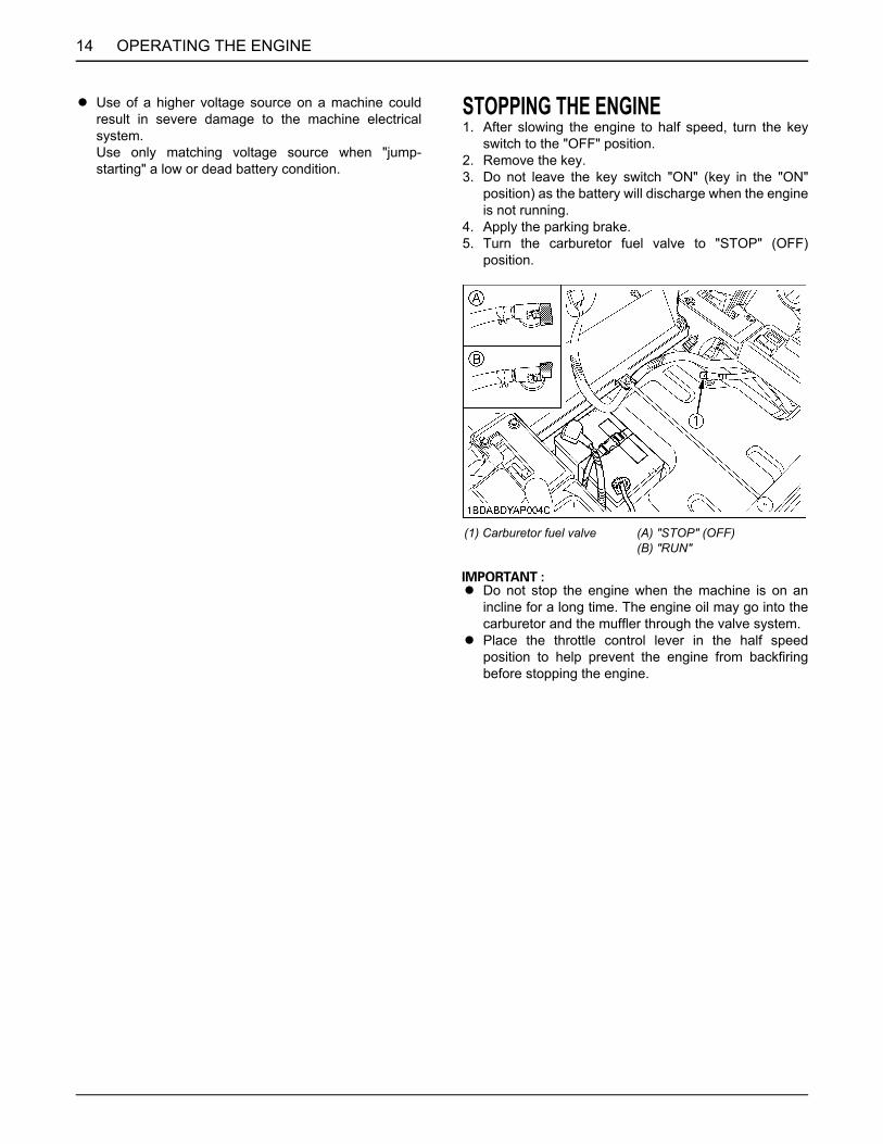
STOPPING THE ENGINE1. After slowing the engine to half speed, turn the key
switch to the "OFF" position.2. Remove the key.3. Do not leave the key switch "ON" (key in the "ON"
position) as the battery will discharge when the engineis not running.
4. Apply the parking brake.5. Turn the carburetor fuel valve to "STOP" (OFF)
position.
A Do not stop the engine when the machine is on anincline for a long time. The engine oil may go into thecarburetor and the muffler through the valve system.
A Place the throttle control lever in the half speedposition to help prevent the engine from backfiringbefore stopping the engine.
(1) Carburetor fuel valve (A) "STOP" (OFF)(B) "RUN"

15OPERATING THE MACHINE
OPERATING THE MACHINE
OPERATING NEW MACHINEHow a new machine is operated and maintained willdetermine the life of the machine.A new machine just off the factory production line hasbeen tested, but the various parts are not accustomed toeach other, so care should be taken to operate themachine for the first 50 hours at a slower speed and avoidexcessive work or operation until the various partsbecome "broken-in." The manner in which the machine ishandled during the "breaking-in" period greatly affects thelife of your machine. Therefore, to obtain the maximumperformance and the longest life of the machine, it is veryimportant to properly break-in your machine. In handling anew machine, the following precautions should beobserved.BChanging Lubricating Oil for New Machines
The lubricating oil is especially important in the case of anew machine. The various parts are not "broken-in" andare not accustomed to each other; small metal grit maydevelop during the operation of the machine; and this maywear out or damage the parts. Therefore, care should betaken to change the lubricating oil a little earlier thanwould ordinarily be required.For further details of change interval hours.(See "SERVICE INTERVALS" in "MAINTENANCE"section.)
BEngine Break-inAfter the first 100 hours of operation, change the engineoil and filter. (See "EVERY 100 HOURS" in "PERIODICSERVICE" section.)
BMachine Break-inAfter the first 100 hours of operation, change the transaxlefluid and oil filter cartridge. (See "EVERY 100 HOURS" in"PERIODIC SERVICE" section.)
To avoid serious injury or death:A Do not operate the mower without the deflector
shield in the down position.
To avoid serious injury or death:A The machine relies upon the engine driven
transmission for speed, direction, and motioncontrol. If the engine is not running, themachine cannot be driven or controlled.If the engine stops when operating on a slope,apply the parking brake immediately to preventmachine runaway.
A Do not allow any person other than the driver toride on the machine.
A Do not drive the machine close to the edges ofditches or banks which may collapse under theweight of the machine, especially when theground is loose or wet.
A When turning the machine, be sure to reducethe travel speed and operate motion controllevers carefully.
A To avoid tip over, operate across slopes, not upand down. Avoid sudden starts and stops onslopes. Slow down, and use extra caution whenchanging direction on a slope.Park the machine on a firm and level surface.
A Watch where you are going at all times. Watchfor and avoid obstacles. Be alert at curbs, neartrees, and other obstructions and hiddenhazards.
A Do not mow near drop-offs, ditches orembankments. The mower could turn over if awheel is over the edge of a cliff or ditch, or if anedge caves in.
A Do not drive machine on streets or highways.Watch for traffic when you cross roads oroperate near roads.
A Look to the rear before and when backing.Make sure the area immediately behind you isclear of obstructions, holes and small children.Use extra caution when machine is equippedwith Grass Catcher.
A Keep bystanders especially children andanimals away from the mowing area.
To avoid serious injury:A Clear the work area of objects which might be
picked up and thrown by blades.A Do not direct the opening of the chute at
bystanders or animals. Ejected objects maycause injury. Plan your mowing carefullybefore starting operation.
A Be sure to disengage the PTO and sit on theoperator's seat before starting the engine.
OPERATING THE MACHINE16
STARTING
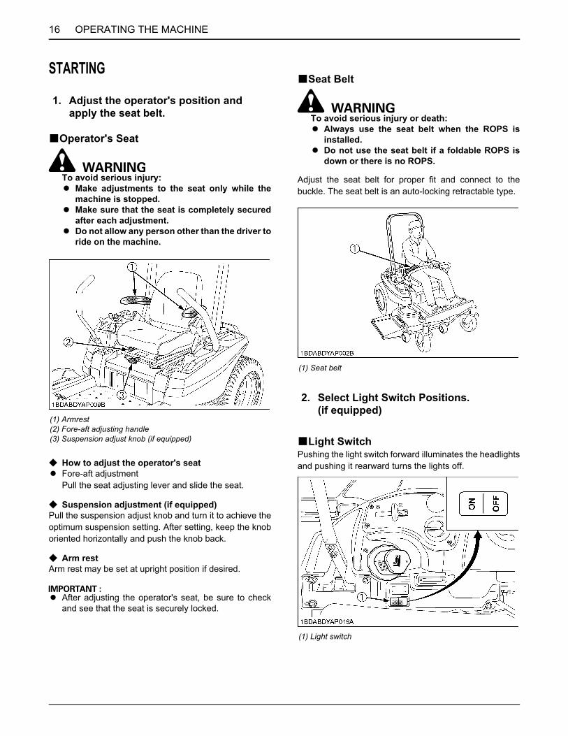
BOperator's Seat
To avoid serious injury:A Make adjustments to the seat only while the
machine is stopped.A Make sure that the seat is completely secured
after each adjustment.A Do not allow any person other than the driver to
ride on the machine.
C How to adjust the operator's seatA Fore-aft adjustment
Pull the seat adjusting lever and slide the seat.
C Suspension adjustment (if equipped)Pull the suspension adjust knob and turn it to achieve theoptimum suspension setting. After setting, keep the knoboriented horizontally and push the knob back.
C Arm restArm rest may be set at upright position if desired.
A After adjusting the operator's seat, be sure to checkand see that the seat is securely locked.
BSeat Belt
To avoid serious injury or death:A Always use the seat belt when the ROPS is
installed.A Do not use the seat belt if a foldable ROPS is
down or there is no ROPS.
Adjust the seat belt for proper fit and connect to thebuckle. The seat belt is an auto-locking retractable type.
BLight SwitchPushing the light switch forward illuminates the headlightsand pushing it rearward turns the lights off.
1. Adjust the operator's position and apply the seat belt.
(1) Armrest(2) Fore-aft adjusting handle(3) Suspension adjust knob (if equipped)
(1) Seat belt
2. Select Light Switch Positions. (if equipped)
(1) Light switch
17OPERATING THE MACHINE
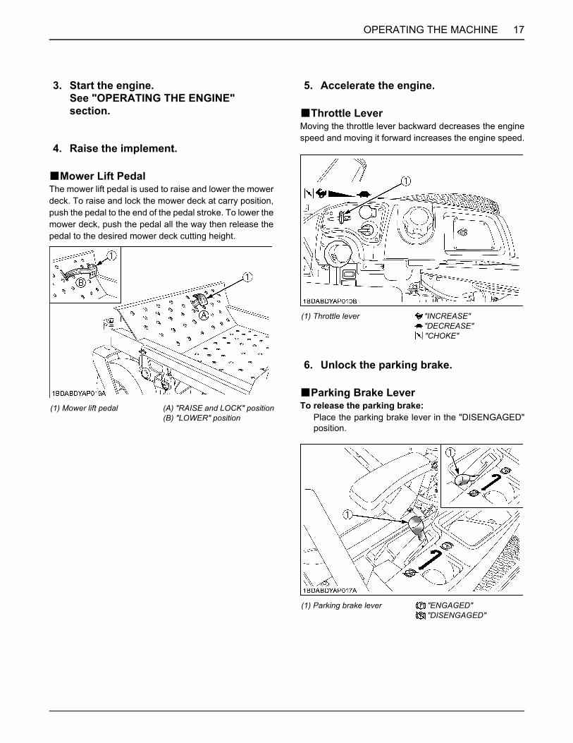
BMower Lift PedalThe mower lift pedal is used to raise and lower the mowerdeck. To raise and lock the mower deck at carry position,push the pedal to the end of the pedal stroke. To lower themower deck, push the pedal all the way then release thepedal to the desired mower deck cutting height.
BThrottle LeverMoving the throttle lever backward decreases the enginespeed and moving it forward increases the engine speed.
BParking Brake LeverTo release the parking brake:
Place the parking brake lever in the "DISENGAGED"position.
3. Start the engine.See "OPERATING THE ENGINE" section.
4. Raise the implement.
(1) Mower lift pedal (A) "RAISE and LOCK" position(B) "LOWER" position
5. Accelerate the engine.
(1) Throttle lever "INCREASE""DECREASE""CHOKE"
6. Unlock the parking brake.
(1) Parking brake lever "ENGAGED""DISENGAGED"

OPERATING THE MACHINE18
BMotion Control Lever
To avoid serious injury:A Understand how to use the motion control
levers and practice in an unrestricted area at alittle more than an idle speed without themower engaged until becoming proficient inthe operation of the machine.
A Do not move motion control levers fromforward to reverse or reverse to forwardposition rapidly.Sudden direction changes could cause loss ofcontrol or damage to the machine or property.
A Do not make sharp turns at high speeds.Fast and sharp turns could cause loss ofcontrol.
A Motion control levers must be in "NEUTRALLOCK" position to safely enter and exit theoperator's seat or to carry out maintenance andsafety checks.
A This machine can make sharp turns. Alwaysmake sure your intended path is clear ofobstructions or persons.
C Neutral lock positionA Forward and reverse movement of the motion control
levers are prevented when levers are in "NEUTRALLOCK" position. (Engine can only be started withlevers in this position.)
Machine speed and steering is controlled by the motioncontrol levers, when the engine is running and the parkingbrake is released.
To avoid serious injury:A No control is provided by the motion control
levers when the engine is off.
C Neutral positionA Grasp the motion control levers and move them
inward from the "NEUTRAL LOCK" position so thatthe machine is in "NEUTRAL". (Engine cannot berestarted.)
C Forward and Reverse Motion:1. Move throttle lever to the "FAST" position.2. Release the parking brake.3. Move both motion control levers from the "NEUTRAL
LOCK" position inward to the "NEUTRAL" position.4. Push the control levers slowly forward to begin forward
motion.To move reverse:Pull both control levers slowly rearward at the sametime to begin reverse motion.To stop:Move and hold both motion control levers to the"NEUTRAL" position until the machine comes to astop.
To avoid serious injury:A The motion control lever adjustment is
important to ensure the machine operatesproperly.
A The motion control linkages are adjustable.If adjustment is required, see "ADJUSTMENT"section. We recommend you to contact your localKUBOTA Dealer.
7. Operate the machine.
Stop position
(1) Motion control levers (A) "NEUTRAL LOCK" position(B) "NEUTRAL" position (held by hand)
Operating position

19OPERATING THE MACHINE
FORWARD:A Push both motion control levers forward equally at the
same time. For forward travel in a straight line.
REVERSE:A Pull both motion control levers past center rearward
equally at the same time. For rearward travel in astraight line.
GENERAL LEFT TURN:A Push right motion control lever further forward than the
left motion control lever. For forward travel to the left.
GENERAL RIGHT TURN:A Push left motion control lever further forward than the
right motion control lever. For forward travel to theright.
SHARP (ZERO) LEFT TURN:A Push right motion control lever forward and pull left
motion control lever rearward at the same time.
SHARP (ZERO) RIGHT TURN:A Push left motion control lever forward and pull right
motion control lever rearward at the same time.
OPERATING THE MACHINE20
STOPPING
To avoid serious injury:A Park the machine on level ground.
If necessary to park on an incline,(1) Stop the machine,(2) Apply the parking brake, then(3) Stop the engine.
A If you stop the engine on an incline withoutapplying the parking brake, the machine couldmove and run away.
A The parking brake lever is for parking use only. If theparking brake is applied when the motion controllevers are not in "NEUTRAL LOCK" position, theengine will stop. This feature is to prevent brake andtransmission damage during operation.
1. Move both motion control levers to the "NEUTRAL"position to stop the machine.
2. Move both motion control levers to "NEUTRAL LOCK"position.
3. Apply parking brake.4. Move the throttle lever to the half speed position and
push PTO switch to the "DISENGAGE" (OFF)position.
5. Lower all implements to the ground.6. Turn off the engine and remove the key.
A Do not stop the engine when the machine is on anincline for a long time. The engine oil may go into thecarburetor and the muffler through the valve system.
A Place the throttle control lever in the half speedposition to help prevent the engine from backfiringbefore stopping the engine.
PARKINGTO LOCK:
Place the parking brake lever in the "ENGAGED"position.
TO UNLOCK:Place the parking brake lever in the "DISENGAGED"position.
To avoid serious injury:Before leaving the operator's position,A Apply parking brake.A Lower all implements to the ground.A Shut off the engine.A Remove the key.A Place the motion control levers in the
"NEUTRAL LOCK" position.
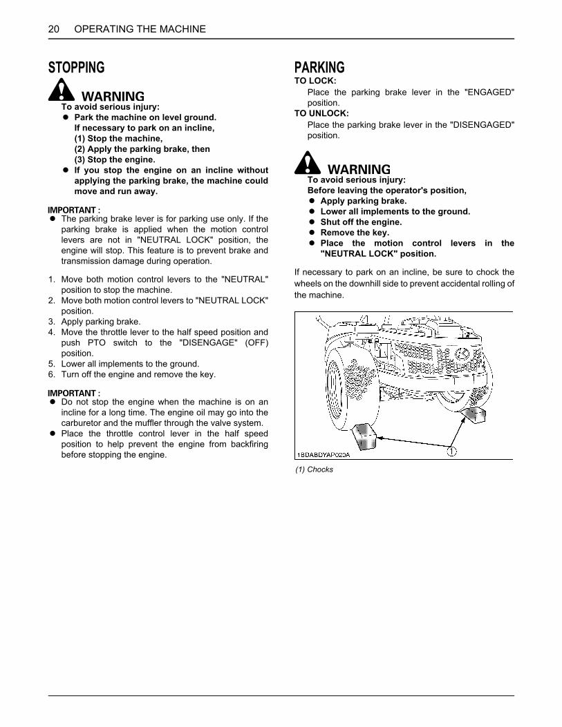
If necessary to park on an incline, be sure to chock thewheels on the downhill side to prevent accidental rolling ofthe machine.
(1) Chocks
21OPERATING THE MACHINE
TRANSPORTING1. Transport the machine on a trailer.
A Turn the carburetor fuel valve to the "OFF"position.
A Fasten the machine to the trailer.2. Do not attempt to tow this machine, or damage to the
transmission may result.3. When transporting the machine over a long distance:
A Make sure to lift the mower by the mower lift pedal.
BHydrostatic Transaxle Bypass Rods
To avoid serious injury:A Do not touch muffler or exhaust pipes while
they are hot; severe burns could result.
A Do not push the machine without pulling the bypassrods, or transmission damage may occur.
A Never pull the rods with the engine running.
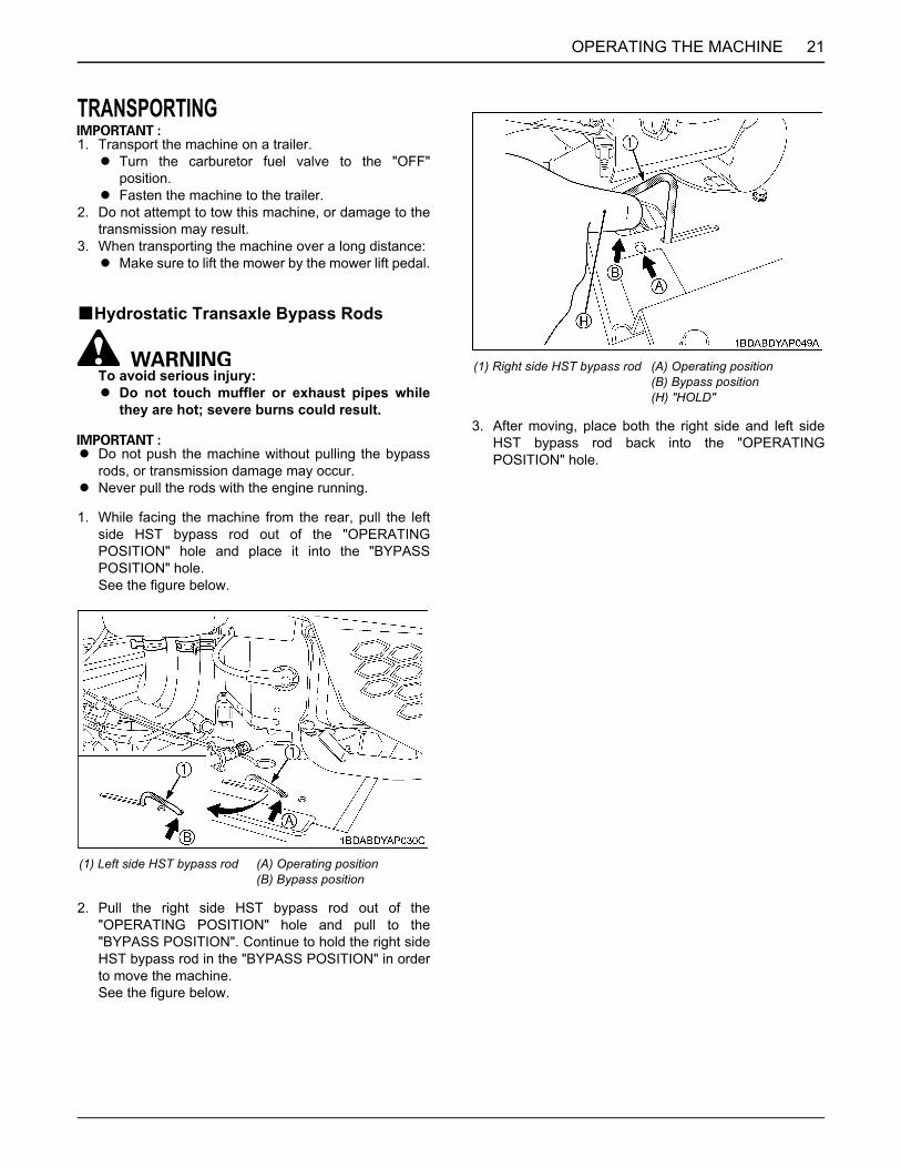
1. While facing the machine from the rear, pull the leftside HST bypass rod out of the "OPERATINGPOSITION" hole and place it into the "BYPASSPOSITION" hole.See the figure below.
2. Pull the right side HST bypass rod out of the"OPERATING POSITION" hole and pull to the"BYPASS POSITION". Continue to hold the right sideHST bypass rod in the "BYPASS POSITION" in orderto move the machine.See the figure below.
3. After moving, place both the right side and left sideHST bypass rod back into the "OPERATINGPOSITION" hole.
(1) Left side HST bypass rod (A) Operating position(B) Bypass position
(1) Right side HST bypass rod (A) Operating position(B) Bypass position(H) "HOLD"
22 OPERATING THE MOWER
OPERATING THE MOWER
MAKING THE MOST OF YOUR MOWER1. When using your mower for the first time, choose asmooth level area and cut in straight and slightlyoverlapping strips.
2. The size and type of the area to be mowed willdetermine the proper mowing pattern. Take intoaccount obstructions, such as trees, fences andbuildings. To keep grass clippings off fences,sidewalks, etc., it is advisable to go over the outside ofthe area to be mowed several times in a clockwisedirection. To mow the area remaining, work in acounterclockwise direction so that the clippings aredispersed onto the previously cut area.
3. Always keep the left side of the mower toward trees,posts or other obstacles on the first trip around theobstacle.
4. Most lawns should be mowed to keep the grassapproximately 50 to 80 mm (2 to 3 in.) high. Bestresults are obtained by cutting often and not too short.To keep a green lawn, never mow more than 1/3 of theheight of the grass or a maximum of 25 mm (1 in.) in 1mowing.For extremely tall grass, set the cutting height atmaximum cutting height for the first mowing, thenreset to the desired height and mow again. Allow thegrass to grow to 80 mm (3 in.), then cut off only the topinch.
5. For best appearance, grass should be cut in theafternoon or evening when it is free of moisture.
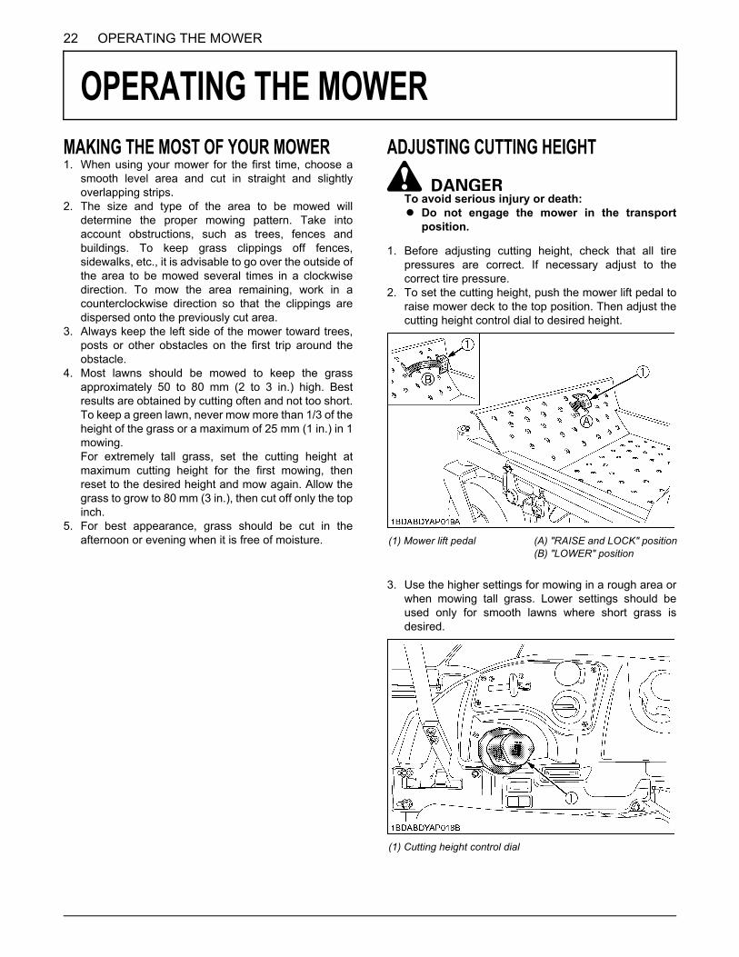
ADJUSTING CUTTING HEIGHT
To avoid serious injury or death:A Do not engage the mower in the transport
position.
1. Before adjusting cutting height, check that all tirepressures are correct. If necessary adjust to thecorrect tire pressure.
2. To set the cutting height, push the mower lift pedal toraise mower deck to the top position. Then adjust thecutting height control dial to desired height.
3. Use the higher settings for mowing in a rough area orwhen mowing tall grass. Lower settings should beused only for smooth lawns where short grass isdesired.
(1) Mower lift pedal (A) "RAISE and LOCK" position(B) "LOWER" position
(1) Cutting height control dial

23OPERATING THE MOWER
4. Lower the mower deck by pushing the mower lift pedalagain. This lowers the mower deck from the"TRANSPORT" position to the "OPERATING"position.
5. Adjust the anti-scalp rollers' height as recommendedbelow for normal operating condition.
A Never allow roller to contact the ground continuouslyas premature roller wear may develop if setincorrectly.
A Anti-scalp rollers must maintain a minimum clearanceof 6 mm (1/4 in.) to the ground.
[BOLT]
A Operation of the mower deck in "TRANSPORT"position is allowed in order to achieve a cutting heightof 4.5".
OPERATING MOWER
To avoid serious injury or death:A Do not operate the mower without the
discharge deflector being in place properly.
To avoid serious injury:A Clear the work area of objects which might be
picked up and thrown.A Do not direct the opening of the deflector at
bystanders especially children or animals.Ejected objects may cause injury. Plan yourmowing carefully before starting operations.
A Keep bystanders and animals away from themowing area.
A Be sure to disengage the PTO clutch of themower before attempting to start the engine.
BPTO SwitchTo engage the PTO, pull the PTO switch to the"ENGAGED" (ON) position.
1. If you get off the seat while the PTO is running, theengine will stop automatically. (Operator presencecontrol)
2. Before starting the engine, push the PTO switch to the"DISENGAGED" (OFF) position. If it is at the"ENGAGED" (ON) position, the engine will not start.
A These interlock features are built-in.
(1) Anti-scalp roller (Front, bolt shift type)
(1) PTO switch "ENGAGED" (ON)
"DISENGAGED" (OFF)

OPERATING THE MOWER24
BStarting
To avoid serious injury:A Engine components can get extremely hot from
operation. To prevent severe burns, do nottouch these areas while the engine is running,or immediately after it is turned off.Never operate the engine without heat shieldsor guards.
1. Sit on the operator's seat.2. Start the engine.3. Engage the PTO switch.4. Disengage the parking brake.5. Speed up the engine by moving the throttle lever
forward.6. Push or pull the motion control levers to move forward
or backward.
A Never attempt to move the machine with the parkingbrake "ON".
A Keep the engine running at full throttle for best results.Control the travel speed with the motion control levers.
A During heavy duty use, operate the machine at aslower ground speed or go over the area twice.
A Keep the mower deck in the raised position when themower is disengaged.
A The mower will not cut cleanly if the ground speed istoo high or if the blade speed drops due to anoverload.
A If debris builds up on the grass screen or other coolingair intake areas, stop the engine and clean them.Operating the engine with blocked or dirty air intakeand cooling areas causes damage due to overheating.

25TIRES AND WHEELS
TIRES AND WHEELS
TIRESTo avoid serious injury:A Do not attempt to mount a tire. This should be
done by a qualified person with the properequipment.
A Always maintain the correct tire pressure.Do not inflate tires above the recommendedpressure shown in the Operator's Manual.
A Inflation pressure in front tires rises quicklywhen using compressed air.
To avoid serious injury:Never operate machine with a loose rim, wheel, oraxle.A Whenever bolts are loosened, retighten to
specified torque.A Check all bolts frequently and keep them
tightened.
BInflation PressureThough the inflation pressure is factory-set to theprescribed level, it naturally drops slowly in the course oftime. Thus, check it everyday and inflate as necessary.
WHEELSA When re-fitting a wheel, tighten the wheel bolt to the
following torques then recheck after traveling 200 m(200 yards) changing directions several times.
Wheels with beveled or tapered holes:Use the tapered wheel nut.
Tire sizes Recommended Inflation Max. Pressure
Front 11 x 4 - 5,4PR Smooth
170 kPa(1.7 kgf/cm , 25 psi)
Rear 22 x 10 - 14, 4PR Turf
110 kPa(1.1 kgf/cm , 16 psi)
(1) Ground (A) "INSUFFICIENT"(B) "NORMAL"(C) "EXCESSIVE"
TIRES AND WHEELS26
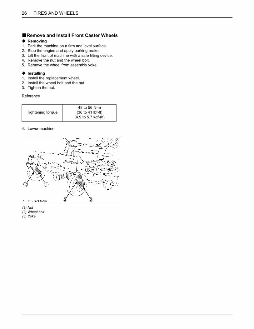
BRemove and Install Front Caster WheelsC Removing1. Park the machine on a firm and level surface.2. Stop the engine and apply parking brake.3. Lift the front of machine with a safe lifting device.4. Remove the nut and the wheel bolt.5. Remove the wheel from assembly yoke.
C Installing1. Install the replacement wheel.2. Install the wheel bolt and the nut.3. Tighten the nut.
Reference
4. Lower machine.
Tightening torque48 to 56 N-m
(36 to 41 lbf-ft)(4.9 to 5.7 kgf-m)
(1) Nut (2) Wheel bolt (3) Yoke
27MAINTENANCE
MAINTENANCE
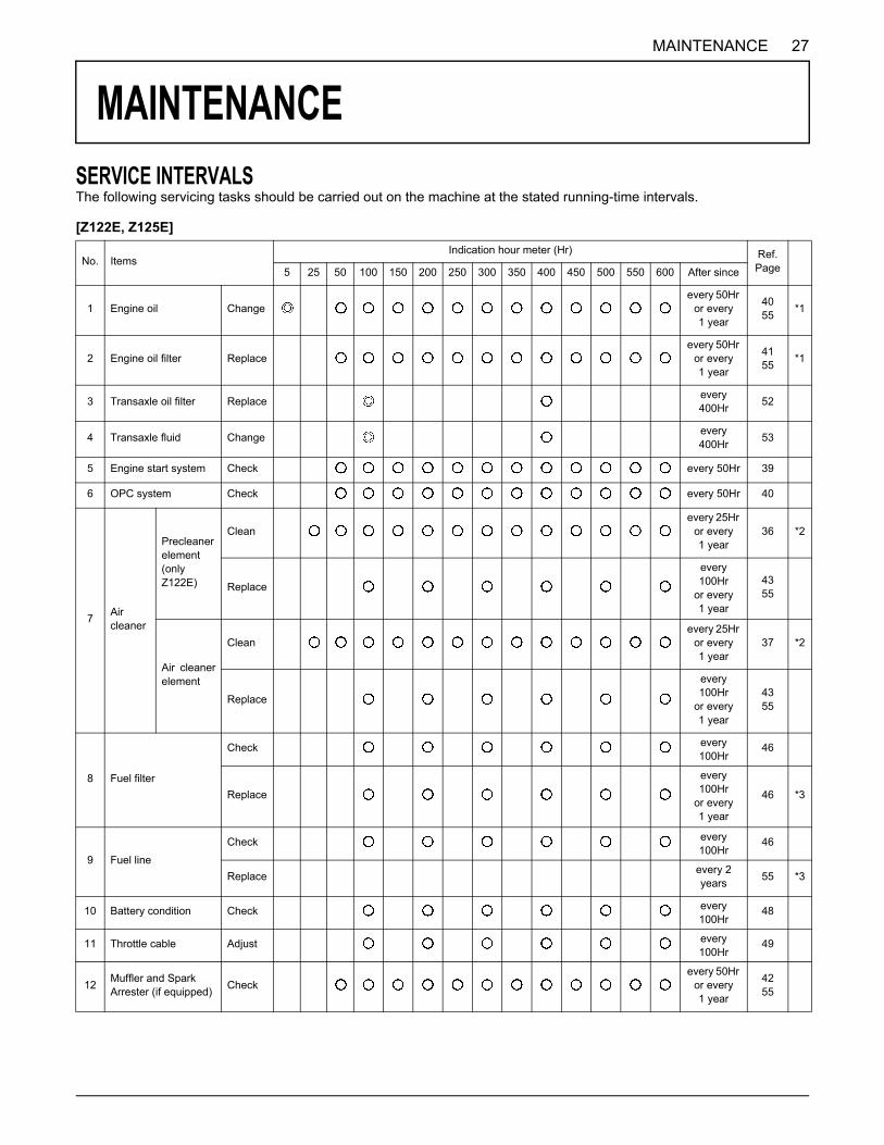
SERVICE INTERVALSThe following servicing tasks should be carried out on the machine at the stated running-time intervals.[Z122E, Z125E]
No. ItemsIndication hour meter (Hr) Ref.
Page5 25 50 100 150 200 250 300 350 400 450 500 550 600 After since
1 Engine oil Changeevery 50Hr
or every1 year
4055 *1
2 Engine oil filter Replaceevery 50Hr
or every 1 year
4155 *1
3 Transaxle oil filter Replace every 400Hr 52
4 Transaxle fluid Change every 400Hr 53
5 Engine start system Check every 50Hr 39
6 OPC system Check every 50Hr 40
7 Air cleaner
Precleaner element (only Z122E)
Cleanevery 25Hr
or every 1 year
36 *2
Replace
every 100Hr
or every 1 year
4355
Air cleanerelement
Cleanevery 25Hr
or every 1 year
37 *2
Replace
every 100Hr
or every 1 year
4355
8 Fuel filter
Check every 100Hr
46
Replace
every 100Hr
or every 1 year
46 *3
9 Fuel line
Check every 100Hr
46
Replace every 2 years 55 *3
10 Battery condition Check every 100Hr
48
11 Throttle cable Adjust every 100Hr
49
12 Muffler and Spark Arrester (if equipped) Check
every 50Hr or every1 year
4255
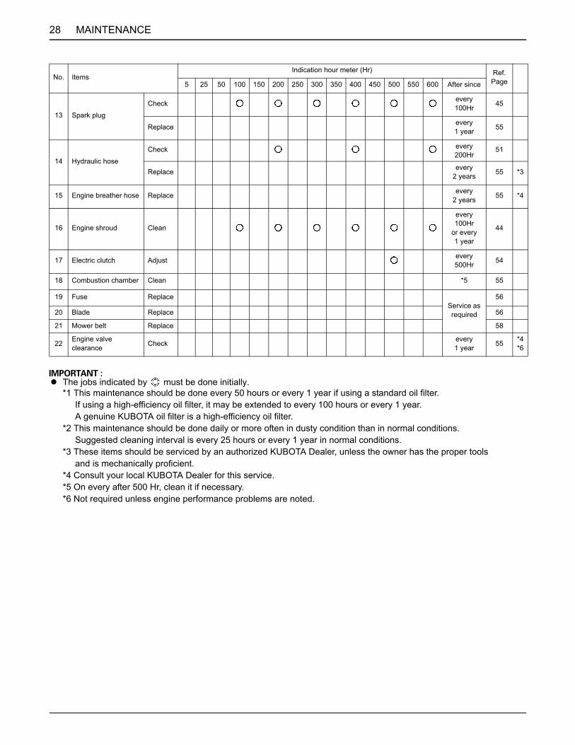
28 MAINTENANCE
A The jobs indicated by must be done initially.*1 This maintenance should be done every 50 hours or every 1 year if using a standard oil filter. If using a high-efficiency oil filter, it may be extended to every 100 hours or every 1 year. A genuine KUBOTA oil filter is a high-efficiency oil filter.*2 This maintenance should be done daily or more often in dusty condition than in normal conditions. Suggested cleaning interval is every 25 hours or every 1 year in normal conditions.*3 These items should be serviced by an authorized KUBOTA Dealer, unless the owner has the proper tools and is mechanically proficient.*4 Consult your local KUBOTA Dealer for this service.*5 On every after 500 Hr, clean it if necessary.*6 Not required unless engine performance problems are noted.
13 Spark plug
Check every 100Hr 45
Replace every1 year 55
14 Hydraulic hose
Check every 200Hr
51
Replace every2 years 55 *3
15 Engine breather hose Replace every2 years 55 *4
16 Engine shroud Clean
every 100Hr
or every 1 year
44
17 Electric clutch Adjust every 500Hr 54
18 Combustion chamber Clean *5 55
19 Fuse ReplaceService as required
56
20 Blade Replace 56
21 Mower belt Replace 58
22 Engine valve clearance Check every
1 year 55 *4*6
No. ItemsIndication hour meter (Hr) Ref.
Page5 25 50 100 150 200 250 300 350 400 450 500 550 600 After since
29MAINTENANCE
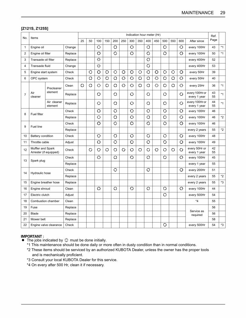
[Z121S, Z125S]
A The jobs indicated by must be done initially.*1 This maintenance should be done daily or more often in dusty condition than in normal conditions.*2 These items should be serviced by an authorized KUBOTA Dealer, unless the owner has the proper tools and is mechanically proficient.*3 Consult your local KUBOTA Dealer for this service.*4 On every after 500 Hr, clean it if necessary.
No. ItemsIndication hour meter (Hr) Ref.
Page25 50 100 150 200 250 300 350 400 450 500 550 600 After since
1 Engine oil Change every 100Hr 43 *1
2 Engine oil filter Replace every 100Hr 50 *1
3 Transaxle oil filter Replace every 400Hr 52
4 Transaxle fluid Change every 400Hr 53
5 Engine start system Check every 50Hr 39
6 OPC system Check every 50Hr 40
7 Air cleaner
Precleaner element
Clean every 25Hr 36 *1
Replace every 100Hr or every 1 year
4355
*1
Air cleanerelement
Replace every 100Hr or every 1 year
4455
*1
8 Fuel filterCheck every 100Hr 46
Replace every 100Hr 46 *2
9 Fuel lineCheck every 100Hr 46
Replace every 2 years 55 *2
10 Battery condition Check every 100Hr 48
11 Throttle cable Adjust every 100Hr 49
12 Muffler and Spark Arrester (if equipped)
Check every 50Hr or every 1 year
4255
13 Spark plugCheck every 100Hr 45
Replace every 1 year 55
14 Hydraulic hoseCheck every 200Hr 51
Replace every 2 years 55 *2
15 Engine breather hose Replace every 2 years 55 *3
16 Engine shroud Clean every 100Hr 44
17 Electric clutch Adjust every 500Hr 54
18 Combustion chamber Clean *4 55
19 Fuse ReplaceService as required
56
20 Blade Replace 56
21 Mower belt Replace 58
22 Engine valve clearance Check every 500Hr 54 *3
30 MAINTENANCE
A GASOLINE ENGINE EMISSION RELATED MAINTENANCE INSTRUCTIONS:1. Non-warranty maintenance, repair, or replacement of the emission control devices and systems should be performed by a qualified repair establishment or individual which has the experience and equipment to perform such work. See the Emissions Warranty Statement.2. To ensure the best quality and reliability, use new KUBOTA Genuine parts or their equivalents for repair and replacement, whenever you have maintenance done.
LUBRICANTS AND FUEL
Note *1 Oil amount when the oil level is at the upper level of the oil level gauge.
C Engine Oil:A Oil used in the engine should have an American Petroleum Institute (API) service classification and proper SAE
Engine Oil according to the ambient temperatures as shown above.A Synthetic oil meeting the listed classifications may be used after 50 hours of run time.
C Fuel:A Clean, fresh, unleaded gasoline.A A minimum of 87 octane / 87AKI (90 RON).A Gasoline with up to 10% ethanol (gasohol) or up to 15% MTBE (methyl tertiary butyl ether) is acceptable.A Do not use unapproved gasoline, such as E85. Do not mix oil in gasoline or modify the engine to run on alternate
fuels. This will damage the engine components and void the engine warranty.A This engine is certified to operate on gasoline. The emissions control system for this engine is EM (Engine
Modifications).A High Altitude:
At altitudes over 5,000 feet (1524 meters), a minimum 85 octane / 85 AKI (89 RON) gasoline is acceptable. Toremain emissions compliant, high altitude adjustment is required. Operation without this adjustment will causedecreased performance, increased fuel consumption, and increased emissions.Operation of the engine at altitudes below 2,500 feet (762 meters) with the high altitude kit is not recommended.
A Indicated capacity of fuel is manufacture's estimate.
PlaceCapacities
LubricantsZ122E Z121S Z125E Z125S
Fuel 16 L (4.2 U.S. gals.) Automobile unleaded or regular gasolineUnleaded gasoline 87 octane or higher
Engine crankcase 1.8 L (1.9 U.S.qts.)*1
Engine oil: API service Classification SG, SH, SJ or higherAbove 10 (50 )...SAE30Between -18 (0 ) to 38 (100 )...SAE10W-30Below 0 (32 )...SAE5W-30
Transmission casewith filter, hose and tank (RH & LH)
4.8 L (5.1 U.S.qts.)Engine oil: API service
Classification SL SAE20W-50
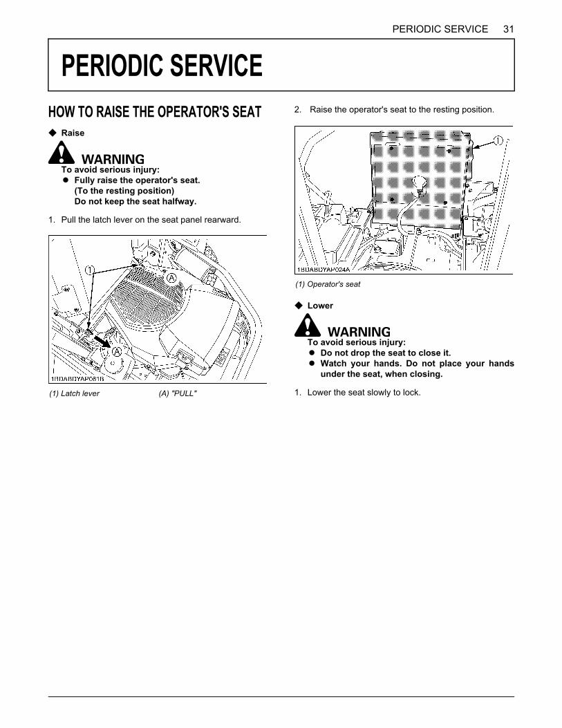
31PERIODIC SERVICE
PERIODIC SERVICE
HOW TO RAISE THE OPERATOR'S SEATC RaiseTo avoid serious injury:A Fully raise the operator's seat.
(To the resting position)Do not keep the seat halfway.
1. Pull the latch lever on the seat panel rearward.
2. Raise the operator's seat to the resting position.
C Lower
To avoid serious injury:A Do not drop the seat to close it.A Watch your hands. Do not place your hands
under the seat, when closing.
1. Lower the seat slowly to lock.(1) Latch lever (A) "PULL"
(1) Operator's seat
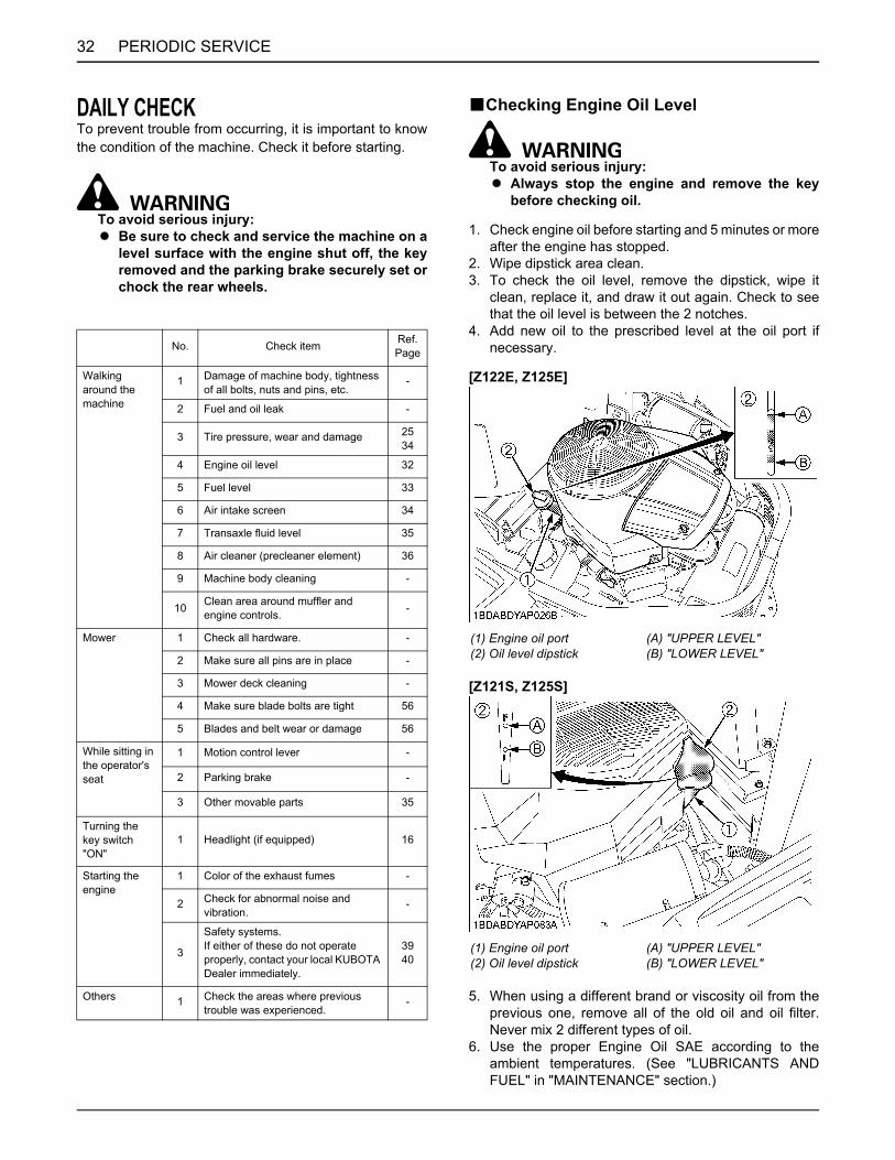
PERIODIC SERVICE32
DAILY CHECKTo prevent trouble from occurring, it is important to knowthe condition of the machine. Check it before starting.
To avoid serious injury:A Be sure to check and service the machine on a
level surface with the engine shut off, the keyremoved and the parking brake securely set orchock the rear wheels.
BChecking Engine Oil Level
To avoid serious injury:A Always stop the engine and remove the key
before checking oil.
1. Check engine oil before starting and 5 minutes or moreafter the engine has stopped.
2. Wipe dipstick area clean.3. To check the oil level, remove the dipstick, wipe it
clean, replace it, and draw it out again. Check to seethat the oil level is between the 2 notches.
4. Add new oil to the prescribed level at the oil port ifnecessary.
[Z122E, Z125E]
[Z121S, Z125S]
5. When using a different brand or viscosity oil from theprevious one, remove all of the old oil and oil filter.Never mix 2 different types of oil.
6. Use the proper Engine Oil SAE according to theambient temperatures. (See "LUBRICANTS ANDFUEL" in "MAINTENANCE" section.)
No. Check item Ref. Page
Walking around the machine
1 Damage of machine body, tightness of all bolts, nuts and pins, etc.
-
2 Fuel and oil leak -
3 Tire pressure, wear and damage 2534
4 Engine oil level 32
5 Fuel level 33
6 Air intake screen 34
7 Transaxle fluid level 35
8 Air cleaner (precleaner element) 36
9 Machine body cleaning -
10 Clean area around muffler and engine controls. -
Mower 1 Check all hardware. -
2 Make sure all pins are in place -
3 Mower deck cleaning -
4 Make sure blade bolts are tight 56
5 Blades and belt wear or damage 56
While sitting in the operator's seat
1 Motion control lever -
2 Parking brake -
3 Other movable parts 35
Turning the key switch "ON"
1 Headlight (if equipped) 16
Starting the engine
1 Color of the exhaust fumes -
2 Check for abnormal noise and vibration.
-
3
Safety systems.If either of these do not operate properly, contact your local KUBOTA Dealer immediately.
3940
Others 1 Check the areas where previous trouble was experienced.
-
(1) Engine oil port(2) Oil level dipstick
(A) "UPPER LEVEL"(B) "LOWER LEVEL"
(1) Engine oil port(2) Oil level dipstick
(A) "UPPER LEVEL"(B) "LOWER LEVEL"

33PERIODIC SERVICE
BChecking Amount of Fuel and Refueling
To avoid serious injury:A Handle fuel carefully. If the engine is running,
do not fill the fuel tank. If engine is hot, letengine cool several minutes before adding fuel.Do not smoke while filling the fuel tank orservicing the fuel system. Fill fuel tank only tobottom of filler neck. Do not fill completely full.The empty space in the tank allows gasoline toexpand, when it heats up. Never remove thefuel tank cap or add fuel when the fuel tank ishot.
Check the fuel level. Take care that the fuel tank does notbecome empty.
A Do not mix oil with gasoline.A Tighten the fuel cap until it clicks.A Do not use the fuel cap other than KUBOTA approved
one.A Do not permit dirt or trash or water to get into the fuel
system.A Be careful not to spill fuel during refueling. If a spill
should occur, wipe it off at once, or it may cause a fire.
Use only unleaded gasoline with an octane rating index of87 or higher may be used.
A Use fuel within approximately 30 days after purchaseto avoid deterioration in fuel quality, or add fuelstabilizer to keep fuel fresh and stabilized.
A Fuel blend differs from season to season for the bestseasonal engine performance. To prevent engineperformance troubles such as vapor lock or hardstarting, use fuel within the season in which the fuel ispurchased.
A Infrequent use of the engine during a season canmake fuel stale in the fuel tank of the machine. Stalefuel condition can cause engine performance troublesby varnish and plugged carburetor components.
A Seal the fuel storage container tightly and store it outof sunlight and heat to prevent fuel degradation.
A Condensation in the fuel tank may occur because ofvarious operating or environmental conditions. Toreduce condensation and avoid affecting machineoperation, fill the fuel tank at the end of dailyoperations.
A Do not use old fuel.
[Use of alcohol mixed gasoline (Gasohol)]Use "gasohol" only when the ethanol additive is less than10% of the fuel. The use of methanol additive is notrecommended. For the best results, use unleaded fuelwith a minimum of 87 octane.
Fuel tank capacity 16 L (4.2 U.S.gals.)
(1) Fuel tank cap(2) Fuel tank filler neck(3) Empty space(4) Max. fuel level
(C) Clearance (Fuel level is under the filler neck.)
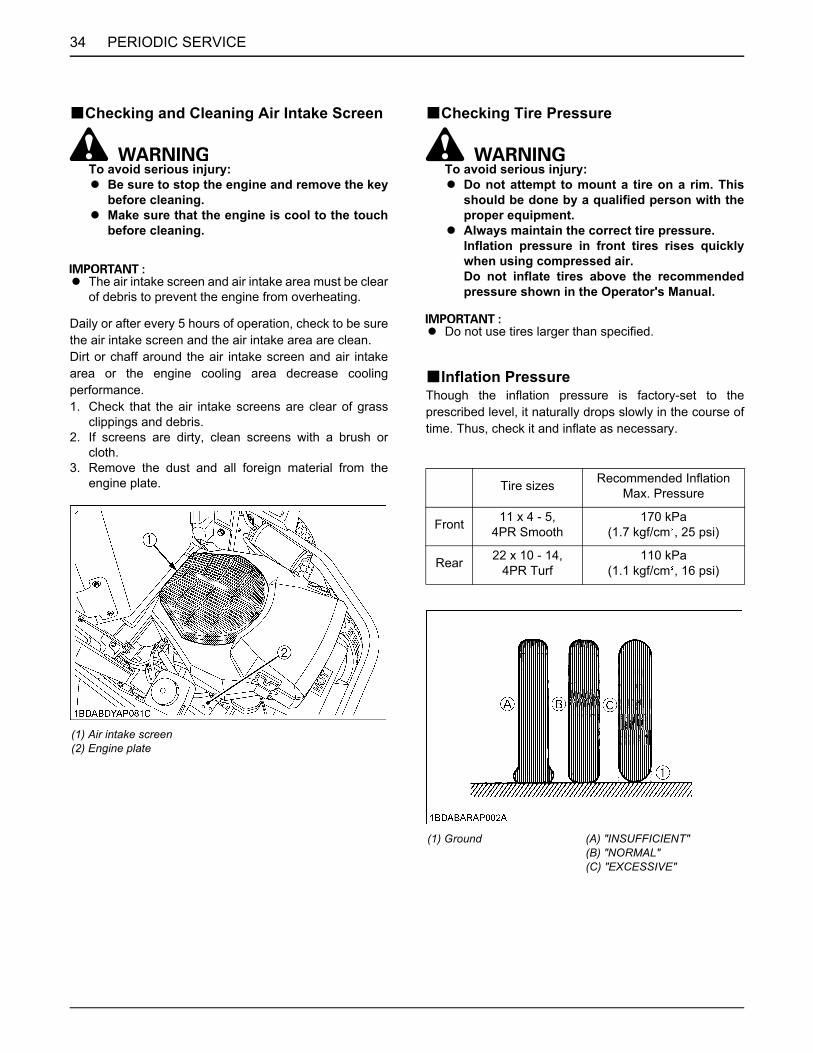
PERIODIC SERVICE34
BChecking and Cleaning Air Intake Screen
To avoid serious injury:A Be sure to stop the engine and remove the key
before cleaning.A Make sure that the engine is cool to the touch
before cleaning.
A The air intake screen and air intake area must be clearof debris to prevent the engine from overheating.
Daily or after every 5 hours of operation, check to be surethe air intake screen and the air intake area are clean.Dirt or chaff around the air intake screen and air intakearea or the engine cooling area decrease coolingperformance.1. Check that the air intake screens are clear of grass
clippings and debris.2. If screens are dirty, clean screens with a brush or
cloth.3. Remove the dust and all foreign material from the
engine plate.
BChecking Tire Pressure
To avoid serious injury:A Do not attempt to mount a tire on a rim. This
should be done by a qualified person with theproper equipment.
A Always maintain the correct tire pressure.Inflation pressure in front tires rises quicklywhen using compressed air.Do not inflate tires above the recommendedpressure shown in the Operator's Manual.
A Do not use tires larger than specified.
BInflation PressureThough the inflation pressure is factory-set to theprescribed level, it naturally drops slowly in the course oftime. Thus, check it and inflate as necessary.
(1) Air intake screen(2) Engine plate
Tire sizes Recommended Inflation Max. Pressure
Front 11 x 4 - 5,4PR Smooth
170 kPa(1.7 kgf/cm , 25 psi)
Rear 22 x 10 - 14,4PR Turf
110 kPa(1.1 kgf/cm , 16 psi)
(1) Ground (A) "INSUFFICIENT"(B) "NORMAL"(C) "EXCESSIVE"

35PERIODIC SERVICE
BChecking Transaxle Fluid Level1. Park the machine on a flat surface, lower the
implement to the ground and shut off the engine andremove the key.
2. Check to see that the oil level lies at the "FULL COLD"line while the machine is at ambient temperature.If the level is too low, add the new oil to the prescribedlevel into the tank.(See "LUBRICANTS AND FUEL" in "MAINTENANCE"section.)
A If oil level is low, do not run engine.Add the new oil to the prescribed level into the tank.
A Do not overfill the tank.
BChecking Movable PartsIf any of the movable parts, such as levers and pedals, isnot smoothly moved because of rust or anything sticky, donot attempt to force it into motion.In the above case, remove the rust or the sticky object,and apply oil or grease on the relevant spot.Otherwise, the machine may get damaged.
(1) Transaxle fluid tank (A) Oil level is acceptable at this line.
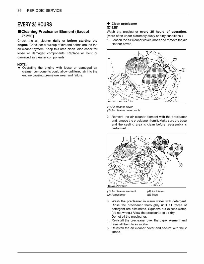
PERIODIC SERVICE36
EVERY 25 HOURSBCleaning Precleaner Element (Except
Z125E)Check the air cleaner daily or before starting theengine. Check for a buildup of dirt and debris around theair cleaner system. Keep this area clean. Also check forloose or damaged components. Replace all bent ordamaged air cleaner components.
A Operating the engine with loose or damaged aircleaner components could allow unfiltered air into theengine causing premature wear and failure.
C Clean precleaner[Z122E]Wash the precleaner every 25 hours of operation.(more often under extremely dusty or dirty conditions.)1. Loosen the air cleaner cover knobs and remove the air
cleaner cover.
2. Remove the air cleaner element with the precleanerand remove the precleaner from it. Make sure the baseand the sealing area is clean before reassembly isperformed.
3. Wash the precleaner in warm water with detergent.Rinse the precleaner thoroughly until all traces ofdetergent are eliminated. Squeeze out excess water.(do not wring.) Allow the precleaner to air dry.Do not oil the precleaner.
4. Reinstall the precleaner over the paper element andreinstall them to air intake.
5. Reinstall the air cleaner cover and secure with the 2knobs.
(1) Air cleaner cover(2) Air cleaner cover knob
(1) Air cleaner element(2) Precleaner
(A) Air intake(B) Base
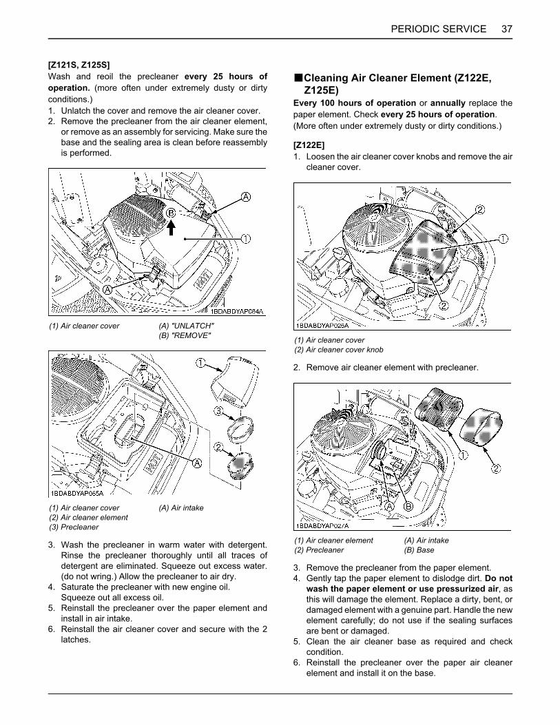
37PERIODIC SERVICE
[Z121S, Z125S]Wash and reoil the precleaner every 25 hours ofoperation. (more often under extremely dusty or dirtyconditions.)1. Unlatch the cover and remove the air cleaner cover.2. Remove the precleaner from the air cleaner element,
or remove as an assembly for servicing. Make sure thebase and the sealing area is clean before reassemblyis performed.
3. Wash the precleaner in warm water with detergent.Rinse the precleaner thoroughly until all traces ofdetergent are eliminated. Squeeze out excess water.(do not wring.) Allow the precleaner to air dry.
4. Saturate the precleaner with new engine oil.Squeeze out all excess oil.
5. Reinstall the precleaner over the paper element andinstall in air intake.
6. Reinstall the air cleaner cover and secure with the 2latches.
BCleaning Air Cleaner Element (Z122E, Z125E)
Every 100 hours of operation or annually replace thepaper element. Check every 25 hours of operation.(More often under extremely dusty or dirty conditions.)
[Z122E]1. Loosen the air cleaner cover knobs and remove the air
cleaner cover.
2. Remove air cleaner element with precleaner.
3. Remove the precleaner from the paper element.4. Gently tap the paper element to dislodge dirt. Do not
wash the paper element or use pressurized air, asthis will damage the element. Replace a dirty, bent, ordamaged element with a genuine part. Handle the newelement carefully; do not use if the sealing surfacesare bent or damaged.
5. Clean the air cleaner base as required and checkcondition.
6. Reinstall the precleaner over the paper air cleanerelement and install it on the base.
(1) Air cleaner cover (A) "UNLATCH"(B) "REMOVE"
(1) Air cleaner cover(2) Air cleaner element(3) Precleaner
(A) Air intake
(1) Air cleaner cover(2) Air cleaner cover knob
(1) Air cleaner element(2) Precleaner
(A) Air intake(B) Base
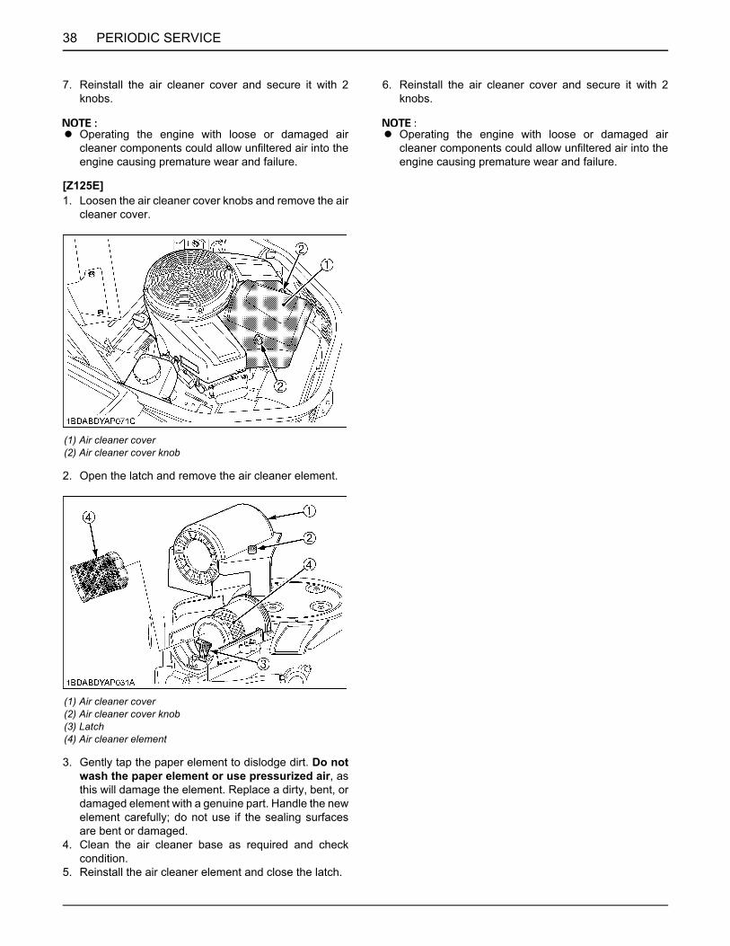
PERIODIC SERVICE38
7. Reinstall the air cleaner cover and secure it with 2knobs.
A Operating the engine with loose or damaged aircleaner components could allow unfiltered air into theengine causing premature wear and failure.
[Z125E]1. Loosen the air cleaner cover knobs and remove the air
cleaner cover.
2. Open the latch and remove the air cleaner element.
3. Gently tap the paper element to dislodge dirt. Do notwash the paper element or use pressurized air, asthis will damage the element. Replace a dirty, bent, ordamaged element with a genuine part. Handle the newelement carefully; do not use if the sealing surfacesare bent or damaged.
4. Clean the air cleaner base as required and checkcondition.
5. Reinstall the air cleaner element and close the latch.
6. Reinstall the air cleaner cover and secure it with 2knobs.
A Operating the engine with loose or damaged aircleaner components could allow unfiltered air into theengine causing premature wear and failure.
(1) Air cleaner cover(2) Air cleaner cover knob
(1) Air cleaner cover(2) Air cleaner cover knob(3) Latch(4) Air cleaner element
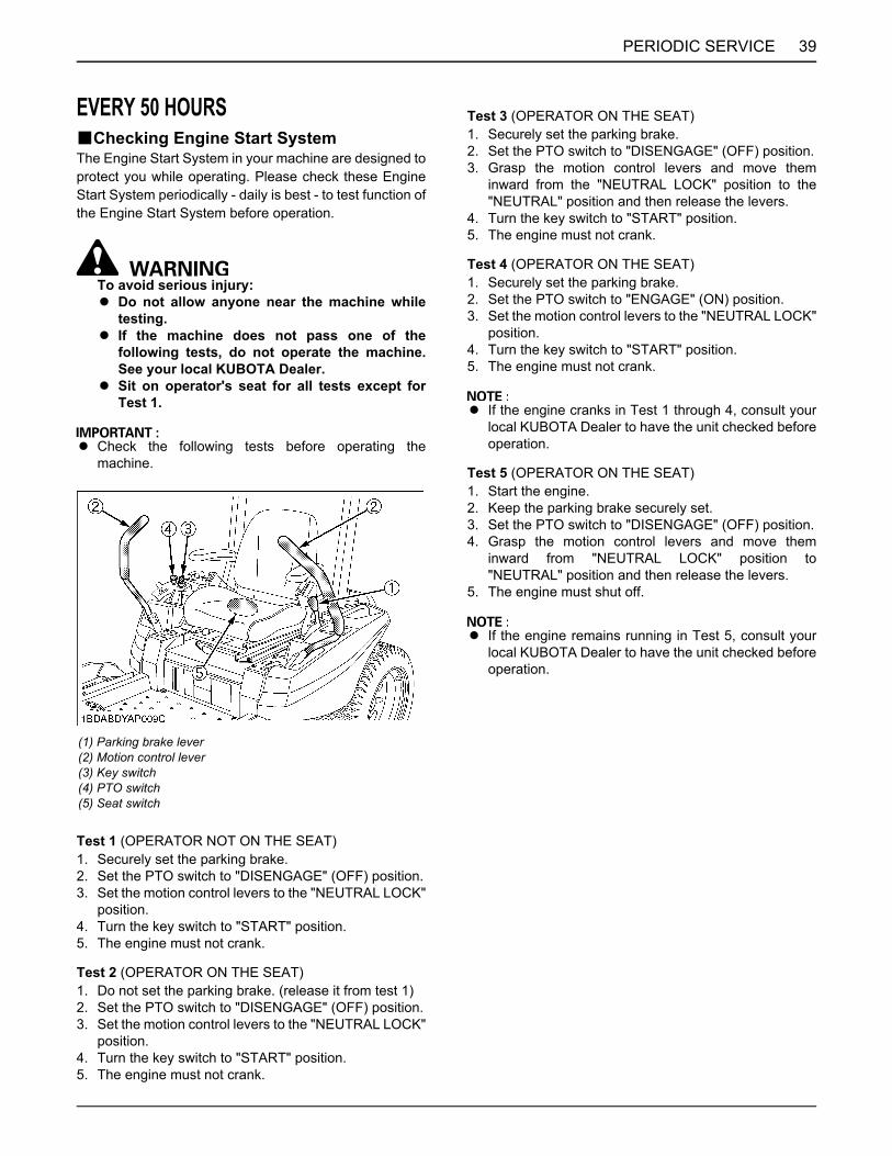
39PERIODIC SERVICE
EVERY 50 HOURSBChecking Engine Start SystemThe Engine Start System in your machine are designed toprotect you while operating. Please check these EngineStart System periodically - daily is best - to test function ofthe Engine Start System before operation.
To avoid serious injury:A Do not allow anyone near the machine while
testing.A If the machine does not pass one of the
following tests, do not operate the machine.See your local KUBOTA Dealer.
A Sit on operator's seat for all tests except forTest 1.
A Check the following tests before operating themachine.
Test 1 (OPERATOR NOT ON THE SEAT)1. Securely set the parking brake.2. Set the PTO switch to "DISENGAGE" (OFF) position.3. Set the motion control levers to the "NEUTRAL LOCK"
position.4. Turn the key switch to "START" position.5. The engine must not crank.
Test 2 (OPERATOR ON THE SEAT)1. Do not set the parking brake. (release it from test 1)2. Set the PTO switch to "DISENGAGE" (OFF) position.3. Set the motion control levers to the "NEUTRAL LOCK"
position.4. Turn the key switch to "START" position.5. The engine must not crank.
Test 3 (OPERATOR ON THE SEAT)1. Securely set the parking brake.2. Set the PTO switch to "DISENGAGE" (OFF) position.3. Grasp the motion control levers and move them
inward from the "NEUTRAL LOCK" position to the"NEUTRAL" position and then release the levers.
4. Turn the key switch to "START" position.5. The engine must not crank.
Test 4 (OPERATOR ON THE SEAT)1. Securely set the parking brake.2. Set the PTO switch to "ENGAGE" (ON) position.3. Set the motion control levers to the "NEUTRAL LOCK"
position.4. Turn the key switch to "START" position.5. The engine must not crank.
A If the engine cranks in Test 1 through 4, consult yourlocal KUBOTA Dealer to have the unit checked beforeoperation.
Test 5 (OPERATOR ON THE SEAT)1. Start the engine.2. Keep the parking brake securely set.3. Set the PTO switch to "DISENGAGE" (OFF) position.4. Grasp the motion control levers and move them
inward from "NEUTRAL LOCK" position to"NEUTRAL" position and then release the levers.
5. The engine must shut off.
A If the engine remains running in Test 5, consult yourlocal KUBOTA Dealer to have the unit checked beforeoperation.
(1) Parking brake lever(2) Motion control lever(3) Key switch(4) PTO switch(5) Seat switch

PERIODIC SERVICE40
BChecking OPC SystemThe OPC (Operator Presence Control) system in yourmachine are designed to protect you while operating.Please check these OPC system periodically - daily isbest - to test function of the OPC system before operation.
To avoid serious injury:A Do not allow anyone near the machine while
testing.A If the machine does not pass one of the
following tests, do not operate the machine.See your local KUBOTA Dealer.
Test 1 (OPERATOR ON THE SEAT)1. Start the engine.2. Do not set the parking brake.3. Set the PTO switch to "DISENGAGE" (OFF) position.4. Stand up. (Do not get off the machine.)5. The engine must shut off.
Test 2 (OPERATOR ON THE SEAT)1. Start the engine.2. Do not set the parking brake.3. Set the PTO switch to "ENGAGE" (ON) position.4. Stand up. (Do not get off the machine.)5. The engine must shut off.
A If the engine remains running in Test 1 through 2,consult your local KUBOTA Dealer to have the unitchecked before operation.
BChanging Engine Oil (Z122E, Z125E)
To avoid serious injury:A Be sure to stop the engine and remove the key
before changing the oil.A Allow engine to cool down sufficiently; oil can
be hot and may cause burns.
1. To change the used oil, unhook the drain hose, directthe hose down and open the drain valve.
A The used oil can be drained out more easily if theengine is warm.
[Z122E, Z125E]
2. Fill with the new oil up to the upper level on thedipstick.
[Z122E]
(1) Parking brake lever(2) Motion control lever(3) Key switch(4) PTO switch(5) Seat switch
(1) Drain hose(2) Drain valve(3) Hook
(1) Engine oil port(2) Oil level dipstick
(A) "UPPER LEVEL"(B) "LOWER LEVEL"
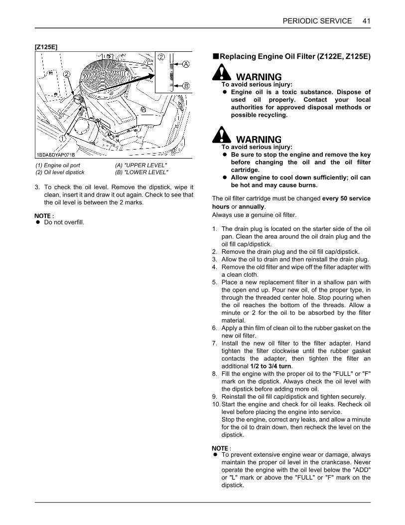
41PERIODIC SERVICE
[Z125E]
3. To check the oil level. Remove the dipstick, wipe itclean, insert it and draw it out again. Check to see thatthe oil level is between the 2 marks.
A Do not overfill.
BReplacing Engine Oil Filter (Z122E, Z125E)
To avoid serious injury:A Engine oil is a toxic substance. Dispose of
used oil properly. Contact your localauthorities for approved disposal methods orpossible recycling.
To avoid serious injury:A Be sure to stop the engine and remove the key
before changing the oil and the oil filtercartridge.
A Allow engine to cool down sufficiently; oil canbe hot and may cause burns.
The oil filter cartridge must be changed every 50 servicehours or annually.Always use a genuine oil filter.
1. The drain plug is located on the starter side of the oilpan. Clean the area around the oil drain plug and theoil fill cap/dipstick.
2. Remove the drain plug and the oil fill cap/dipstick.3. Allow the oil to drain and then reinstall the drain plug.4. Remove the old filter and wipe off the filter adapter with
a clean cloth.5. Place a new replacement filter in a shallow pan with
the open end up. Pour new oil, of the proper type, inthrough the threaded center hole. Stop pouring whenthe oil reaches the bottom of the threads. Allow aminute or 2 for the oil to be absorbed by the filtermaterial.
6. Apply a thin film of clean oil to the rubber gasket on thenew oil filter.
7. Install the new oil filter to the filter adapter. Handtighten the filter clockwise until the rubber gasketcontacts the adapter, then tighten the filter anadditional 1/2 to 3/4 turn.
8. Fill the engine with the proper oil to the "FULL" or "F"mark on the dipstick. Always check the oil level withthe dipstick before adding more oil.
9. Reinstall the oil fill cap/dipstick and tighten securely.10.Start the engine and check for oil leaks. Recheck oil
level before placing the engine into service.Stop the engine, correct any leaks, and allow a minutefor the oil to drain down, then recheck the level on thedipstick.
A To prevent extensive engine wear or damage, alwaysmaintain the proper oil level in the crankcase. Neveroperate the engine with the oil level below the "ADD"or "L" mark or above the "FULL" or "F" mark on thedipstick.
(1) Engine oil port(2) Oil level dipstick
(A) "UPPER LEVEL"(B) "LOWER LEVEL"

PERIODIC SERVICE42
BChecking Muffler and Spark Arrester (if equipped)
Running engines produce heat. Engine parts,especially muffler, become extremely hot.Severe thermal burns can occur on contact.Combustible debris, such as leaves, grass, brush,etc. can catch fire.To avoid serious injury:A Allow muffler, engine cylinder and fins to cool
before touching.A Remove accumulated debris from muffler area
and cylinder area.A It is a violation of California Public Resource
Code, Section 4442, to use or operate theengine on any forest-covered, brush-covered,or grass-covered land unless the exhaustsystem is equipped with a spark arrester, asdefined in Section 4442, maintained in effectiveworking order. Other states or federaljurisdictions may have similar laws. Contactthe original equipment manufacturer, retailer,or dealer to obtain a spark arrester designedfor the exhaust system installed on this engine.
A Replacement parts must be of the same designand installed in the same position as theoriginal parts. Other parts may not perform aswell, may damage the unit, and may result ininjury.
Remove accumulated debris from muffler area andcylinder area. Inspect the muffler for cracks, corrosion, orother damage. Remove the spark arrester, if equipped,and inspect for damage or carbon blockage. If damage isfound, install replacement parts before operating.
(1) Engine oil filter cartridge (A) "MOUNTING SURFACE"

43PERIODIC SERVICE
EVERY 100 HOURSBChanging Engine Oil (Z121S, Z125S)
To avoid serious injury:A Be sure to stop the engine and remove the key
before changing the oil.A Allow engine to cool down sufficiently; oil can
be hot and may cause burns.
1. To change the used oil, remove the drain hose fromthe clamp, direct the hose down and remove the drainplug.
A The used oil can be drained out more easily if theengine is warm.
[Z121S, Z125S]
2. Fill with the new oil up to the upper level on thedipstick.
[Z121S, Z125S]
3. To check the oil level. Remove the dipstick, wipe itclean, insert it and draw it out again. Check to see thatthe oil level is between the 2 marks.
A Do not overfill.
BReplacing Precleaner Element (Except Z125E)
(See "Cleaning Precleaner Element (Except Z125E)" in"EVERY 25 HOURS" in "PERIODIC SERVICE" section.)
BReplacing Air Cleaner Element (Z122E, Z125E)
(See "Cleaning Air Cleaner Element (Z122E, Z125E)" in"EVERY 25 HOURS" in "PERIODIC SERVICE" section.)
(1) Drain plug
(1) Engine oil port(2) Oil level dipstick
(A) "UPPER LEVEL"(B) "LOWER LEVEL"

PERIODIC SERVICE44
BReplacing Air Cleaner Element (Z121S, Z125S)
Every 100 hours of operation or annually replace thepaper element.
[Z121S, Z125S]1. Unlatch the cover and remove the air cleaner cover.2. Remove the air cleaner element and precleaner.
3. Remove the precleaner from the paper element.
4. Replace a dirty, bent, or damaged element with agenuine part. Handle the new element carefully; do notuse if the sealing surfaces are bent or damaged.
5. Clean the air cleaner base as required and checkcondition.
6. Reinstall the precleaner over the paper element andinstall in air intake.
7. Reinstall the air cleaner cover and secure with the 2latches.
A Operating the engine with loose or damaged aircleaner components could allow unfiltered air into theengine causing premature wear and failure.
BCleaning Engine Shroud
To avoid serious injury:A Make sure engine is cool to the touch before
removing shrouds.
1. Remove the engine shroud mounting bolts and detachthe shroud.
2. Check to see if the engine's cooling fins are blockedwith dust and dirt. Clean them with compressed air ifrequired.
To avoid serious injury:A Always shield eyes and face from air deposits
and objects.
[Z122E](1) Air cleaner cover (A) "UNLATCH"(B) "REMOVE"
(1) Air cleaner cover(2) Air cleaner element(3) Precleaner
(A) Air intake
(1) Shroud
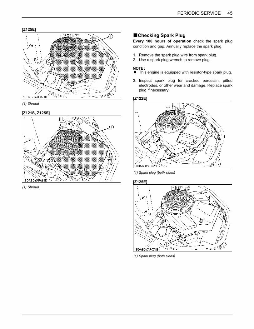
45PERIODIC SERVICE
[Z125E]
[Z121S, Z125S]
BChecking Spark PlugEvery 100 hours of operation check the spark plugcondition and gap. Annually replace the spark plug.
1. Remove the spark plug wire from spark plug.2. Use a spark plug wrench to remove plug.
A This engine is equipped with resistor-type spark plug.
3. Inspect spark plug for cracked porcelain, pittedelectrodes, or other wear and damage. Replace sparkplug if necessary.
[Z122E]
[Z125E]
(1) Shroud
(1) Shroud
(1) Spark plug (both sides)
(1) Spark plug (both sides)

PERIODIC SERVICE46
[Z121S, Z125S]
4. Check spark plug gap with gap gauge.
BChecking Fuel Lines
To avoid serious injury:A Be sure to stop the engine and remove the key
when attempting to make the following checksand changes.
A Never fail to check the fuel lines periodically.The fuel lines are subject to wear and aging.Fuel may leak out onto the running engine,causing a fire.
The fuel line connections should be checked annually orevery 100 hours of operation, whichever occurs first.1. The fuel line is made of rubber and ages regardless of
service period.2. If the fuel line, clamps and fuel filter are found
damaged or deteriorated, replace them.
A When the fuel line is disconnected for maintenance orrepair, close both ends of the fuel line with a piece ofclean cloth or paper to prevent dust and dirt fromentering. In addition, particular care must be taken notto admit dust and dirt into the fuel pump. Entrance ofdust and dirt causes malfunction of the fuel pump.
(1) Spark plug (both sides)
Recommended spark plug CHAMPION XC12YC
(A) 0.76 mm (0.03 in.)
(1) Fuel valve(2) Fuel tank(3) Fuel line(4) Pipe clamp
(A) "CLOSE" (OFF)(B) "OPEN"
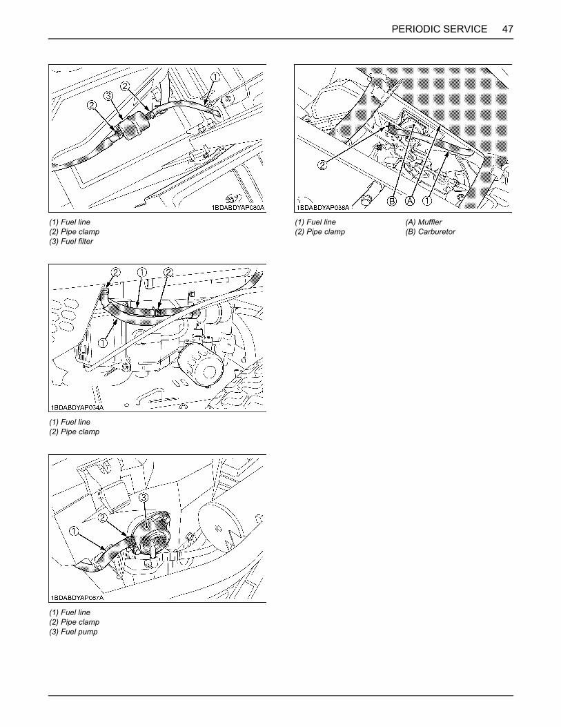
47PERIODIC SERVICE
(1) Fuel line(2) Pipe clamp(3) Fuel filter
(1) Fuel line(2) Pipe clamp
(1) Fuel line(2) Pipe clamp(3) Fuel pump
(1) Fuel line(2) Pipe clamp
(A) Muffler(B) Carburetor

PERIODIC SERVICE48
BBattery Condition
To avoid the possibility of battery explosion:For the refillable type battery, follow theinstructions below.A Do not use or charge the refillable type battery
if the fluid level is below the LOWER (lower limitlevel) mark. Otherwise, the battery componentparts may prematurely deteriorate, which mayshorten the battery's service life or cause anexplosion. Check the fluid level regularly andadd distilled water as required so that the fluidlevel is between the UPPER and LOWER levels.
To avoid serious injury or death:A When the battery is being activated, hydrogen
and oxygen gases in the battery are extremelyexplosive. Keep open sparks and flames awayfrom the battery at all times, especially whencharging the battery.
To avoid serious injury:A Batteries, battery posts, terminals and related
accessories contain lead and lead compounds,and other chemicals known to the State ofCalifornia to cause cancer and birth defects orother reproductive harm. WASH HANDSAFTER HANDLING.
A Never remove the battery cap while the engineis running.
A Keep electrolyte away from eyes, hands andclothes. If you are spattered with it, wash itaway completely with water immediately andget medical attention.
A Keep open sparks and flames away from thebattery at all times. Hydrogen gas mixed withoxygen becomes very explosive.
A Wear eye protection and rubber gloves whenworking around battery.
A Mishandling the battery shortens the service life andadds to maintenance costs.The original battery is maintenance free, but needssome servicing.If the battery is weak, the engine will be difficult to startand the lights will be dim. It is important to check thebattery periodically.
A When exchanging an old battery for new one, usebattery of equal specification in table below.
(For non-accessible maintenance-free type batteries.)Maintenance-free, non-accessible batteries are designedto eliminate the need to add water. Yet the volume ofelectrolyte above plates may eventually become depleteddue to abnormal conditions such as high heat or improperregulator setting. Use a voltmeter to check the state ofcharge. (See reference chart below to determine ifcharging is necessary.)
C Battery Charging
To avoid serious injury or death:A When the battery is being activated, hydrogen
and oxygen gases in the battery are extremelyexplosive. Keep open sparks and flames awayfrom the battery at all times, especially whencharging the battery.
To avoid serious injury:A When disconnecting the cable from the battery,
start with the negative terminal first. Whenconnecting the cable to the battery, start withthe positive terminal first.
A Never check battery charge by placing a metalobject across the posts.Use a voltmeter or hydrometer.
The factory-installed battery is of non-refillable type.If the battery is weak, charge the battery or replace it with new one.
Battery Type
Volts (V)
Reserve Capacity
(min)
Cold Cranking
Amps
Normal Charging Rate(A)
U1-300 12 45 300 6.5
Battery voltage Reference state of charge
12.6 100%(Full charge)
12.4 75%
12.2 50%
12.0 25%
11.8 0%

49PERIODIC SERVICE
1. To slow charge the battery, connect the batterypositive terminal to the charger positive terminal andthe negative to the negative, then charge for at least 1hour at 6.5 amperes.
2. A boost charge is only for emergencies. It will partiallycharge the battery at a high rate and in a short time.When using a boost-charged battery, it is necessary torecharge the battery as early as possible.Failure to do this will shorten the battery's service life.
3. When the specific gravity of electrolyte is between1.27 and 1.29 the charging is completed.
C Battery for storage1. When storing the machine for a long period, remove
the battery from machine, adjust the electrolyte to theproper level and store in a dry place out of directsunlight.
2. The battery self-discharges while it is stored.Recharge it once every 3 months in hot seasons andonce every 6 months in cold seasons.
BAdjusting Throttle Cable[Z122E, Z125E]1. Move the throttle lever to the "FAST" position.
2. Attempt to pass a pin (A) with a diameter of 3 mmthrough the holes indicated.
3. If not possible, loosen the bolt (1) and pull the throttlelever cable sheath (2) in the direction of the arrow sothat the pin (A) passes through all the required holes(B). And then tighten the bolt (1).
(1) Battery(2) Ground cable
(+): Positive terminal(-): Negative terminal
(1) Throttle lever
(1) Bolt(2) Throttle lever cable sheath
(A) Pin with a diameter of 3 mm(B) Hole(P) "PULL"
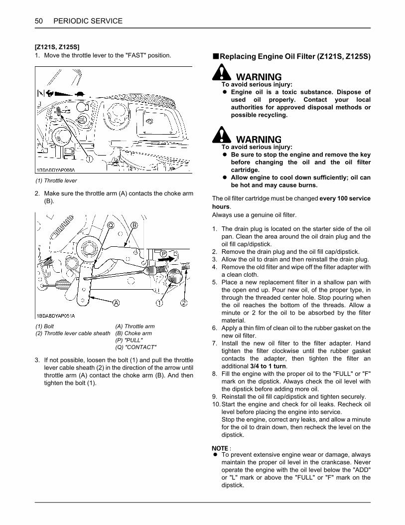
PERIODIC SERVICE50
[Z121S, Z125S]1. Move the throttle lever to the "FAST" position.
2. Make sure the throttle arm (A) contacts the choke arm(B).
3. If not possible, loosen the bolt (1) and pull the throttlelever cable sheath (2) in the direction of the arrow untilthrottle arm (A) contact the choke arm (B). And thentighten the bolt (1).
BReplacing Engine Oil Filter (Z121S, Z125S)
To avoid serious injury:A Engine oil is a toxic substance. Dispose of
used oil properly. Contact your localauthorities for approved disposal methods orpossible recycling.
To avoid serious injury:A Be sure to stop the engine and remove the key
before changing the oil and the oil filtercartridge.
A Allow engine to cool down sufficiently; oil canbe hot and may cause burns.
The oil filter cartridge must be changed every 100 servicehours.Always use a genuine oil filter.
1. The drain plug is located on the starter side of the oilpan. Clean the area around the oil drain plug and theoil fill cap/dipstick.
2. Remove the drain plug and the oil fill cap/dipstick.3. Allow the oil to drain and then reinstall the drain plug.4. Remove the old filter and wipe off the filter adapter with
a clean cloth.5. Place a new replacement filter in a shallow pan with
the open end up. Pour new oil, of the proper type, inthrough the threaded center hole. Stop pouring whenthe oil reaches the bottom of the threads. Allow aminute or 2 for the oil to be absorbed by the filtermaterial.
6. Apply a thin film of clean oil to the rubber gasket on thenew oil filter.
7. Install the new oil filter to the filter adapter. Handtighten the filter clockwise until the rubber gasketcontacts the adapter, then tighten the filter anadditional 3/4 to 1 turn.
8. Fill the engine with the proper oil to the "FULL" or "F"mark on the dipstick. Always check the oil level withthe dipstick before adding more oil.
9. Reinstall the oil fill cap/dipstick and tighten securely.10.Start the engine and check for oil leaks. Recheck oil
level before placing the engine into service.Stop the engine, correct any leaks, and allow a minutefor the oil to drain down, then recheck the level on thedipstick.
A To prevent extensive engine wear or damage, alwaysmaintain the proper oil level in the crankcase. Neveroperate the engine with the oil level below the "ADD"or "L" mark or above the "FULL" or "F" mark on thedipstick.
(1) Throttle lever
(1) Bolt(2) Throttle lever cable sheath
(A) Throttle arm(B) Choke arm(P) "PULL"(Q) "CONTACT"
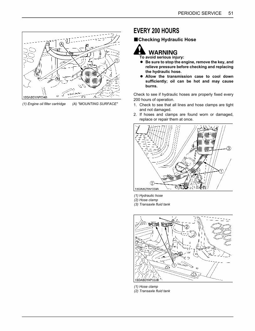
51PERIODIC SERVICE
EVERY 200 HOURSBChecking Hydraulic Hose
To avoid serious injury:A Be sure to stop the engine, remove the key, and
relieve pressure before checking and replacingthe hydraulic hose.
A Allow the transmission case to cool downsufficiently; oil can be hot and may causeburns.
Check to see if hydraulic hoses are properly fixed every200 hours of operation.1. Check to see that all lines and hose clamps are tight
and not damaged.2. If hoses and clamps are found worn or damaged,
replace or repair them at once.
(1) Engine oil filter cartridge (A) "MOUNTING SURFACE"
(1) Hydraulic hose(2) Hose clamp(3) Transaxle fluid tank
(1) Hose clamp(2) Transaxle fluid tank

PERIODIC SERVICE52
EVERY 400 HOURSBReplacing Transaxle Oil Filter Cartridge
To avoid serious injury:A Park the machine on a firm and level surface.A Apply the parking brake.A Be sure to stop the engine and remove the key
before changing or checking the oil.A Allow transmission case to cool down
sufficiently; oil can be hot and may causeburns.
1. Apply the bypass valve.(See "Hydrostatic Transaxle Bypass Rods" in"TRANSPORTING" in "OPERATING THE MACHINE"section.)
2. Remove the hex head bolts (4), and filter guard (3).Clean any loose debris from around the perimeter ofthe oil filter (2).
3. Place an oil drain pan (12" or more diameter and 8 qt.capacity is optimal) beneath the oil filter. Remove theoil filter (2) and discard it.
A Always replace the filter when preforming any internalmaintenance to the transaxle.
4. After the oil has drained, inspect all parts for excessivewear or damage. Replace if necessary.
5. Wipe the filter base surface off and apply a film of newoil to the gasket of the new replacement filter (Hydro-Gear part number 52114).
6. Install the new filter by hand, turn 3/4 to 1 full turn afterthe filter gasket contacts the filter base surface.
(1) Hose clamp(2) Hydraulic hose
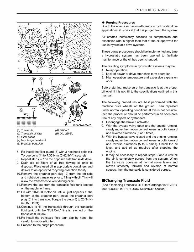
53PERIODIC SERVICE
7. Re-install the filter guard (3) with 3 hex head bolts (4).Torque bolts (4) to 7.35 N-m (5.42 lbf-ft) securely.
8. Repeat steps 2-7 on the opposite side transaxle drive.9. Drain old oil filters of all free flowing oil prior to
disposal. Place used oil in appropriate containers anddeliver to an approved recycling collection facility.
10.Remove the breather port plug (9) from the left sideand right side transaxles prior to filling with oil. This willallow the transaxles to vent during oil fill.
11.Remove the cap from the transaxle fluid tank locatedon the machine frame.
12.Fill with 20W-50 motor oil until oil just appears at thebottom of the breather port. Install the breather portplug (5) into transaxle. Torque the plug (5) to 20.34 N-m (15.0 lbf-ft).
13.Continue to fill the transaxles through the transaxlefluid tank until the "Full Cold" line is reached on thetransaxle fluid tank.
14.Re-install the transaxle fluid tank cap by hand. Becareful to not overtighten.
15.Proceed to the purge procedure.
C Purging ProceduresDue to the effects air has on efficiency in hydrostatic driveapplications, it is critical that it is purged from the system.
Air creates inefficiency because its compression andexpansion rate is higher than that of the oil approved foruse in hydrostatic drive systems.
These purge procedures should be implemented any timea hydrostatic system has been opened to facilitatemaintenance or the oil has been changed.
The resulting symptoms in hydrostatic systems may be:1. Noisy operation.2. Lack of power or drive after short term operation.3. High operation temperature and excessive expansion
of oil.
Before starting, make sure the transaxle is at the properoil level. If it is not, fill to the specifications outlined in thismanual.
The following procedures are best performed with themachine drive wheels off the ground. Then repeatedunder normal operating conditions. If this is not possible,then the procedure should be performed in an open areafree of any objects or bystanders.1. Disengage the brake if activated.2. With the bypass valve open and the engine running,
slowly move the motion control levers in both forwardand reverse directions (5 or 6 times).
3. With the bypass valve closed and the engine running,slowly move the motion control levers in both forwardand reverse directions (5 to 6 times). Check the oillevel, and add oil as required after stopping theengine.
4. It may be necessary to repeat Steps 2 and 3 until allthe air is completely purged from the system. Whenthe transaxle operates at normal noise levels andmoves smoothly forward and reverse at normalspeeds, then the transaxle is considered purged.
BChanging Transaxle Fluid(See "Replacing Transaxle Oil Filter Cartridge" in "EVERY400 HOURS" in "PERIODIC SERVICE" section.)
(1) Transaxle(2) Transaxle oil filter(3) Filter guard(4) Hex flange head bolt(5) Breather port plug
(A) FRONT(B) OIL LEVEL

PERIODIC SERVICE54
EVERY 500 HOURSBElectric Clutch AdjustmentThe electric clutch serves 2 functions in the operation ofthe mower. In addition to starting and stopping the powerflow to the cutter blades, the clutch also acts as a brake toassist in stopping blade rotation when the PTO is switchedoff or the operator presence control is interrupted.
When the clutch is disengaged, the air gap between thearmature and rotor must be adjusted to 0.4 mm (0.015 in.)for proper operation. The air gap adjustment is made at 3bolts on the clutch. There are 3 inspection windows, onenext to each adjusting bolt. (See the figure below.)
1. Locate the inspection windows on the clutch.2. Place a 0.4 mm (0.015 in.) feeler gauge in the slot
between the rotor and the armature. (See the figure.)
3. Tighten or loosen the adjusting nut as needed toachieve the 0.4 mm (0.015 in.) air gap. (See thefigure.) Perform this operation at all 3 inspectionwindows.
This adjustment should be done every 500 hours ofoperation or annually, whichever comes first. In caseswhere the machine is heavily used, air gap settings shouldbe checked more often.
If the air gap is too narrow, the clutch armature may dragwhen disengaged, resulting in premature failure.
BChecking Engine Valve Clearance (Z121S, Z125S)
Consult your local KUBOTA Dealer for this service.
(1) Inspection window (x3) (A) Electric clutch
(A) Electric clutch(P) "INSERT 0.4 mm (0.015 in.) FEELER GAUGE HERE"
(A) Electric clutch(Q) Adjustment nut

55PERIODIC SERVICE
EVERY AFTER 500 HOURSBCleaning Combustion ChamberIf you do not have the proper tools and/or are notmechanically proficient, consult your local KUBOTADealer for this service.
EVERY 1 YEARBReplacing Precleaner Element (Except
Z125E)(See "Cleaning Precleaner Element (Except Z125E)" in"EVERY 25 HOURS" in "PERIODIC SERVICE" section.)
BReplacing Air Cleaner Element (Z122E, Z125E)
(See "Cleaning Air Cleaner Element (Z122E, Z125E)" in"EVERY 25 HOURS" in "PERIODIC SERVICE" section.)
BReplacing Air Cleaner Element (Z121S, Z125S)
(See "Replacing Air Cleaner Element (Z121S, Z125S)" in"EVERY 100 HOURS" in "PERIODIC SERVICE" section.)
BChanging Engine Oil (Z122E, Z125E)(See "Changing Engine Oil (Z122E, Z125E)" in "EVERY50 HOURS" in "PERIODIC SERVICE" section.)
BReplacing Engine Oil Filter (Z122E, Z125E)(See "Replacing Engine Oil Filter (Z122E, Z125E)" in"EVERY 50 HOURS" in "PERIODIC SERVICE" section.)
BReplacing Fuel Filter (Z122E, Z125E)(See "Checking Fuel Lines" in "EVERY 100 HOURS" in"PERIODIC SERVICE" section.)
BChecking Muffler and Spark Arrester (if equipped)
(See "Checking Muffler and Spark Arrester (if equipped)"in "EVERY 50 HOURS" in "PERIODIC SERVICE"section.)
BReplacing Spark Plug(See "Checking Spark Plug" in "EVERY 100 HOURS" in"PERIODIC SERVICE" section.)
BChecking Engine Valve Clearance (Z122E, Z125E)
Consult your local KUBOTA Dealer for this service.
EVERY 2 YEARSBReplacing Hydraulic HoseConsult your local KUBOTA Dealer for this service.
BReplacing Fuel LinesConsult your local KUBOTA Dealer for this service.
BReplacing Engine Breather HoseConsult your local KUBOTA Dealer for this service.
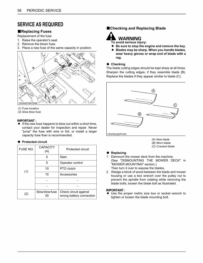
PERIODIC SERVICE56
SERVICE AS REQUIREDBReplacing FusesReplacement of the fuse1. Raise the operator's seat.2. Remove the blown fuse.3. Place a new fuse of the same capacity in position.
A If the new fuse happens to blow out within a short time,contact your dealer for inspection and repair. Never"jump" the fuse with wire or foil, or install a largercapacity fuse than is recommended.
C Protected circuit
BChecking and Replacing Blade
To avoid serious injury:A Be sure to stop the engine and remove the key.A Blades may be sharp. When you handle blades,
wear heavy gloves or wrap end of blade with arag.
C CheckingThe blade cutting edges should be kept sharp at all times.Sharpen the cutting edges, if they resemble blade (B).Replace the blades if they appear similar to blade (C).
C Replacing1. Dismount the mower deck from the machine.
(See "DISMOUNTING THE MOWER DECK" in"MOWER MOUNTING" section.)Then turn it over to expose the blades.
2. Wedge a block of wood between the blade and mowerhousing or use a box wrench over the pulley nut toprevent the spindle from rotating while removing theblade bolts; loosen the blade bolt as illustrated.
A Use the proper metric size box or socket wrench totighten or loosen the blade mounting bolt.
(1) Fuse location(2) Slow blow fuse
FUSE NO. CAPACITY(A) Protected circuit
(1)
5 Start
5 Operator control
10 PTO clutch
15 Accessories
- -
- -
(2) Slow blow fuse 30
Check circuit againstwrong battery connection
(A) New blade(B) Worn blade(C) Cracked blade

57PERIODIC SERVICE
3. To sharpen the blades yourself, clamp the bladesecurely in a vise.Use a large mill file and file along the original beveluntil sharp.
4. To check the blade for balance, place a small rodthrough the center hole. If the blade is not balanced,file the heavy side of the blade until balance isachieved.
5. To attach blades, be sure to install the cup washerbetween the blade and bolt head. Then tighten the boltsecurely.
6. Before checking or replacing the blade, wipe grassand mud off the top and inside of the mower.Especially clean up the inside of the belt cover,because otherwise the belt life will be reduced.
[RCK48P, RCK54P]
A Tighten the bolts of the outer blades from 103 to 118N-m (76 to 87 lbf-ft) of torque.
A The blade bolts have Right hand threads. Turn themcounterclockwise to loosen.
A To prolong the service life of the blades, repositionthem as shown in the figure below periodically.
(1) Block (A) "LOOSEN"
(1) Spindle holder(2) Blade(3) Cup washer(4) Bolt
(1) LH blade(2) Center blade(3) RH blade
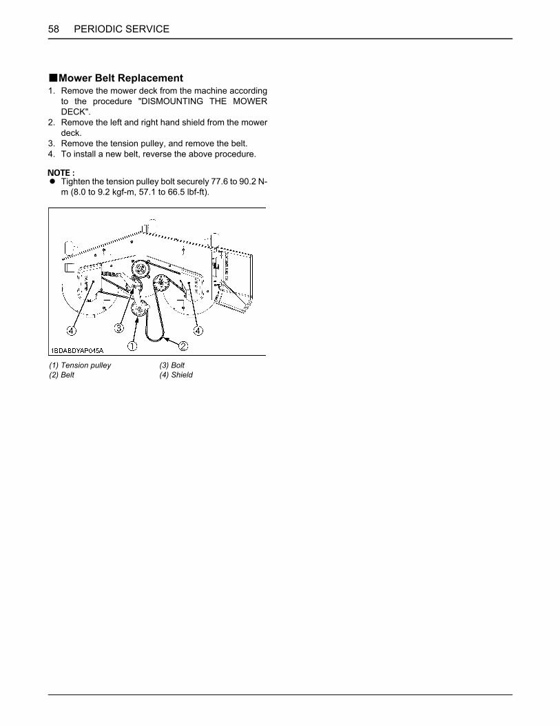
PERIODIC SERVICE58
BMower Belt Replacement1. Remove the mower deck from the machine according
to the procedure "DISMOUNTING THE MOWERDECK".
2. Remove the left and right hand shield from the mowerdeck.
3. Remove the tension pulley, and remove the belt.4. To install a new belt, reverse the above procedure.
A Tighten the tension pulley bolt securely 77.6 to 90.2 N-m (8.0 to 9.2 kgf-m, 57.1 to 66.5 lbf-ft).
(1) Tension pulley(2) Belt
(3) Bolt(4) Shield

59ADJUSTMENT
ADJUSTMENT
MOTION CONTROL LEVERTo avoid serious injury:A Park the machine on a firm and level surface.A If it is necessary to run the engine in an
enclosed area, use a gas tight exhaust pipeextension to remove the fumes.
A Always try to work in a well-ventilated area.A Lift up and secure with jack stands or blocking
the rear of the machine, do not run the machinewhile adjusting.Remove rear wheels.
A Do not adjust only one of the followingadjustments; exclude "MOTION CONTROLLEVER ALIGNMENT".They are interlinked.
A If you feel you are unable to make the followingadjustments correctly and safely, pleasecontact your local KUBOTA Dealer.
A Right and left motion control levers can be adjustedindependently.
BHST NEUTRAL1. Lift-up and secure with jack stands or blocking the rear
of the machine frame.2. Remove both rear wheels.3. Start the engine, and run at maximum speed.4. Place the motion control lever in "NEUTRAL LOCK"
position.5. Loosen the 3 bolts of the guide plate.
Adjust the guide plate position until the rear axlerotation stops.
6. Tighten the rear bolt and place the lever in "NEUTRALLOCK" position. Check that the rear axle does notrotate.If the axle does not stop rotating, adjust the "HSTNEUTRAL" again.
7. Adjust the other side "HST NEUTRAL" equally.8. After adjustment, make sure to stop the engine
immediately.
[RH]
Tightening torque23.6 to 27.4 N-m(2.4 to 2.8 kgf-m,17.4 to 20.2 lbf-ft)
(1) Guide plate(2) Speed adjust plate(3) Bolt (front)(4) Bolt (rear)
(A) Motion control lever
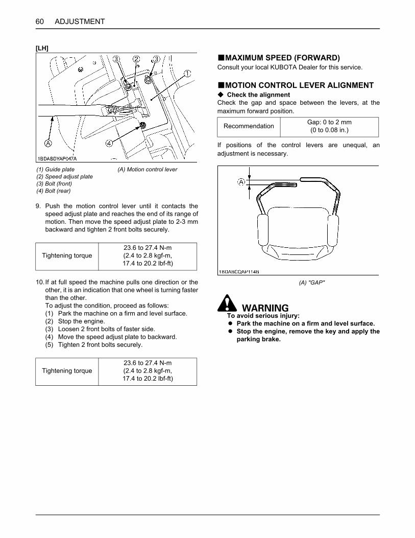
ADJUSTMENT60
[LH]
9. Push the motion control lever until it contacts thespeed adjust plate and reaches the end of its range ofmotion. Then move the speed adjust plate to 2-3 mmbackward and tighten 2 front bolts securely.
10. If at full speed the machine pulls one direction or theother, it is an indication that one wheel is turning fasterthan the other. To adjust the condition, proceed as follows:(1) Park the machine on a firm and level surface.(2) Stop the engine.(3) Loosen 2 front bolts of faster side.(4) Move the speed adjust plate to backward.(5) Tighten 2 front bolts securely.
BMAXIMUM SPEED (FORWARD)Consult your local KUBOTA Dealer for this service.
BMOTION CONTROL LEVER ALIGNMENTC Check the alignmentCheck the gap and space between the levers, at themaximum forward position.
If positions of the control levers are unequal, anadjustment is necessary.
To avoid serious injury:A Park the machine on a firm and level surface.A Stop the engine, remove the key and apply the
parking brake.
(1) Guide plate(2) Speed adjust plate(3) Bolt (front)(4) Bolt (rear)
(A) Motion control lever
Tightening torque23.6 to 27.4 N-m(2.4 to 2.8 kgf-m,17.4 to 20.2 lbf-ft)
Tightening torque23.6 to 27.4 N-m(2.4 to 2.8 kgf-m,17.4 to 20.2 lbf-ft)
Recommendation Gap: 0 to 2 mm(0 to 0.08 in.)
(A) "GAP"

61ADJUSTMENT
C Aligning the control levers
1. Stop the engine and apply the parking brake.
Lever position (High or Low)2. Remove the bolts and select the motion control lever
position, high or low.3. Tighten the bolts.
Lever alignment (Right and Left)4. Loosen the bolts.5. Slide both levers forward or rearward to the desired
position within tab slots until levers are aligned.6. Tighten the bolts.
MOWER DECK LEVELBANTI-SCALP ROLLERS
To avoid serious injury:A Park the machine on a firm and level surface.A Apply the parking brake.A Stop the engine and remove the key.A Wait for all moving parts to stop.
A The flattest cut can be achieved by having the anti-scalp rollers adjusted off the ground.Check anti-scalp roller adjustments each time themower deck cutting height is changed.It is recommended that all the anti-scalp rollers be keptoff the ground to minimize scuffing.
1. Check the machine tire pressure.Inflate tires to the correct pressure. (See "TIRES ANDWHEELS" section.)
2. Start the engine.3. Raise up the mower deck to the transport position.
(Also the top end of the lift.)4. Turn the cutting height control dial to adjust height.5. Lower the mower deck.6. Adjust the height of the front side anti-scalp roller to
one of 4 positions to approximately 19 mm (3/4 in.)between rollers and the ground.Adjust 3 rollers to the same height.
7. Install the roller with attaching hardware.
(1) Bolt(2) Flange nut(3) Tab slot
(A) High position
(1) Front side anti-scalp roller (H) 19 mm (3/4 in.)

ADJUSTMENT62
BLEVEL MOWER DECK (Side-to-Side)
To avoid serious injury:A Park the machine on a firm and level surface.A Apply the parking brake.A Disengage PTO (OFF).A Stop the engine and remove the key while
checking or adjusting the level of the mowerdeck.
A Check the machine tire pressure.Inflate tires to the correct pressure.(See "TIRES AND WHEELS" section.)
C Checking level (Side-to-Side)
A Mower deck anti-scalp rollers should not contact theground.
1. Raise the mower deck to the transport position. (Alsothe top end).
2. Turn the cutting height set dial to the 3 in. cuttingheight position.
3. Lower the mower deck.4. Position the right mower blade in the Side-to-Side
position.5. Measure from outside blade tip to the level surface
with a short ruler or leveling gauge.
Reference
A There is a difference of the blade height between onthe flat surface and ground.
6. Check that the left side blade is same height.The difference between both measurements shouldbe less than 3 mm (1/8 in.).
7. If the Side-to-Side adjustment is not within the giventolerance, adjustment is necessary.
C Adjusting level (Side-to-Side)1. Raise up the mower deck to the transport position.
(Also the top end).2. Turn the cutting height set dial to the 3 in. cutting
height position.3. Place 51 mm (2 in.) height wood blocks under each
side of the mower deck.Anti-scalp rollers must not rest on the wood block.
4. Lower the mower deck.5. Position mower blade in the Side-to-Side position.6. Loosen the jam nuts of the right side of the machine.7. Adjust the cutting height fine tuning bolts to set 76
mm (3 in.) blade height.Front and rear side bolts must be adjusted.
8. Jam the nuts.9. Adjust the left side equally.10.Check the side-to-side level and if it is not level,
adjustment is necessary.
Height of the bladeat the flat surface 76 mm (3 in.)
Side-to-Side adjustment Less than 3 mm (1/8 in.)
(S) Side
(1) Cutting height fine tuning bolt(2) Jam nut

63ADJUSTMENT
BLEVEL MOWER DECK (Front-to-Rear)
To avoid serious injury:A Park the machine on a firm and level surface.A Engage the parking brake.A Disengage PTO.A Stop the engine and remove the key while
checking or adjusting the level of the mowerdeck.
A Check the machine tire pressure.Inflate tires to the correct pressure.(See "TIRES AND WHEELS" section.)
C Checking level (Front-to-Rear)
A Mower deck anti-scalp rollers should not contact theground.
1. Raise the mower deck to the transport position. (Alsothe top end).
2. Turn the cutting height set dial to the 3 in. cuttingheight position.
3. Lower the mower deck.4. Position the right mower blade in the Front-to-Rear
position.5. Measure from the right front blade tip to the level
surface with a short ruler or leveling gauge.6. Turn the blade 180 and measure from right rear blade
tip to the level surface.7. Check that the left side blade has the same dimension.
The difference between both measurements shouldbe less than 6 mm (1/4 in.).Front side must be lower than rear side.
8. If the Front-to-Rear adjustment is not within the giventolerance, adjustment is necessary.
C Adjusting level (Front-to-Rear)1. Raise up the mower deck to the transport position.
(Also the top end).2. Turn the cutting height set dial to the 3 in. cutting
height position.3. Place 51 mm (2 in.) height wood blocks under each
side of the mower deck.Anti-scalp rollers must not rest on the wood block.
4. Lower the mower deck.5. Loosen the jam nuts of the front side of the machine.6. Adjust the cutting height fine tuning bolts to set 76 mm
(3 in.) blade height.Both front side bolts must be adjusted.
7. Jam the nuts.8. Adjust the other side equally.
A The difference between both measurements shouldbe less than 6 mm (1/4 in.).Front side must be lower than rear side.
9. Check the front-to-rear level and if it is not level,adjustment is necessary.
(A) Front(B) Rear
Front-to-Rearadjustment
Less than 6 mm (1/4 in.)Front side must be lower
than Rear side.
(1) Cutting height fine tuning bolt(2) Jam nut
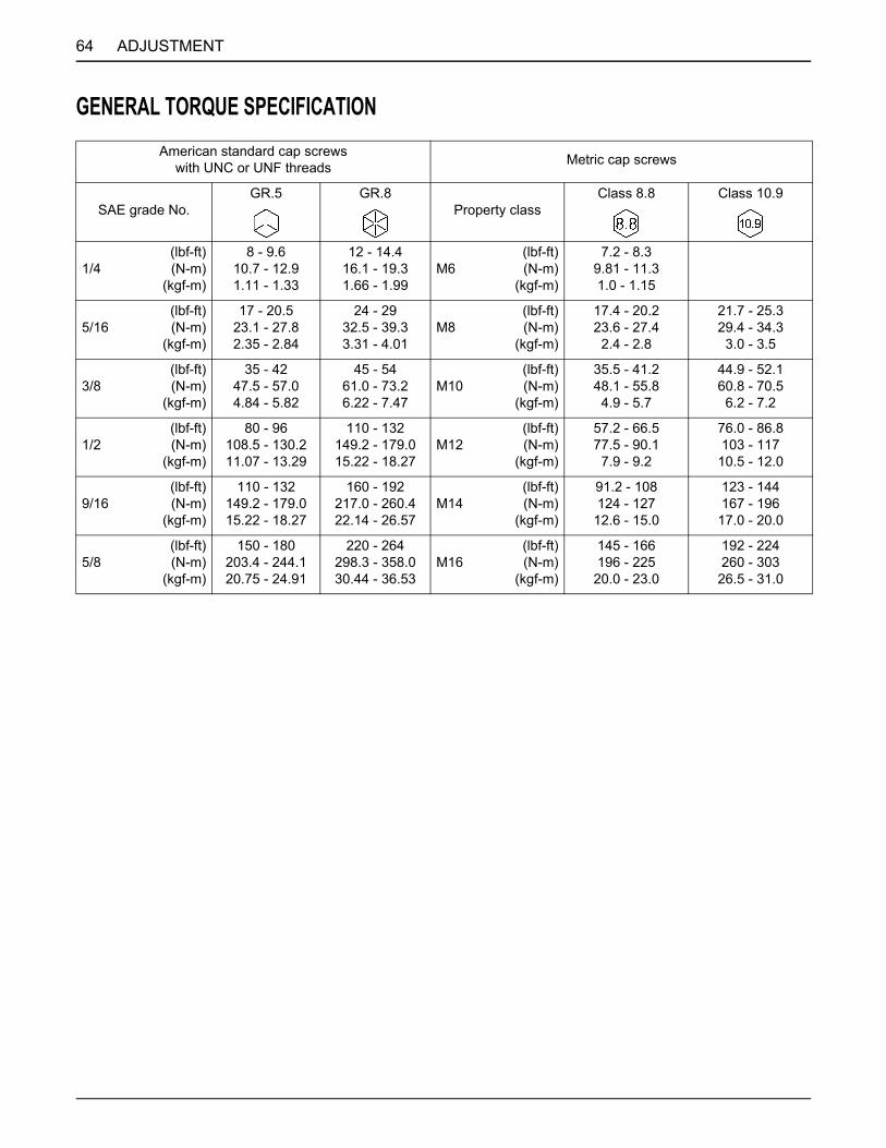
64 ADJUSTMENT
GENERAL TORQUE SPECIFICATIONAmerican standard cap screws
with UNC or UNF threads Metric cap screws
SAE grade No.GR.5 GR.8
Property classClass 8.8 Class 10.9
1/4(lbf-ft)(N-m)
(kgf-m)
8 - 9.610.7 - 12.91.11 - 1.33
12 - 14.416.1 - 19.31.66 - 1.99
M6(lbf-ft)(N-m)
(kgf-m)
7.2 - 8.39.81 - 11.31.0 - 1.15
5/16(lbf-ft)(N-m)
(kgf-m)
17 - 20.523.1 - 27.82.35 - 2.84
24 - 2932.5 - 39.33.31 - 4.01
M8(lbf-ft)(N-m)
(kgf-m)
17.4 - 20.223.6 - 27.4
2.4 - 2.8
21.7 - 25.329.4 - 34.3
3.0 - 3.5
3/8(lbf-ft)(N-m)
(kgf-m)
35 - 4247.5 - 57.04.84 - 5.82
45 - 5461.0 - 73.26.22 - 7.47
M10(lbf-ft)(N-m)
(kgf-m)
35.5 - 41.248.1 - 55.8
4.9 - 5.7
44.9 - 52.160.8 - 70.5
6.2 - 7.2
1/2(lbf-ft)(N-m)
(kgf-m)
80 - 96108.5 - 130.211.07 - 13.29
110 - 132149.2 - 179.015.22 - 18.27
M12(lbf-ft)(N-m)
(kgf-m)
57.2 - 66.577.5 - 90.1
7.9 - 9.2
76.0 - 86.8103 - 117
10.5 - 12.0
9/16(lbf-ft)(N-m)
(kgf-m)
110 - 132149.2 - 179.015.22 - 18.27
160 - 192217.0 - 260.422.14 - 26.57
M14(lbf-ft)(N-m)
(kgf-m)
91.2 - 108124 - 127
12.6 - 15.0
123 - 144167 - 196
17.0 - 20.0
5/8(lbf-ft)(N-m)
(kgf-m)
150 - 180203.4 - 244.120.75 - 24.91
220 - 264298.3 - 358.030.44 - 36.53
M16(lbf-ft)(N-m)
(kgf-m)
145 - 166196 - 225
20.0 - 23.0
192 - 224260 - 303
26.5 - 31.0
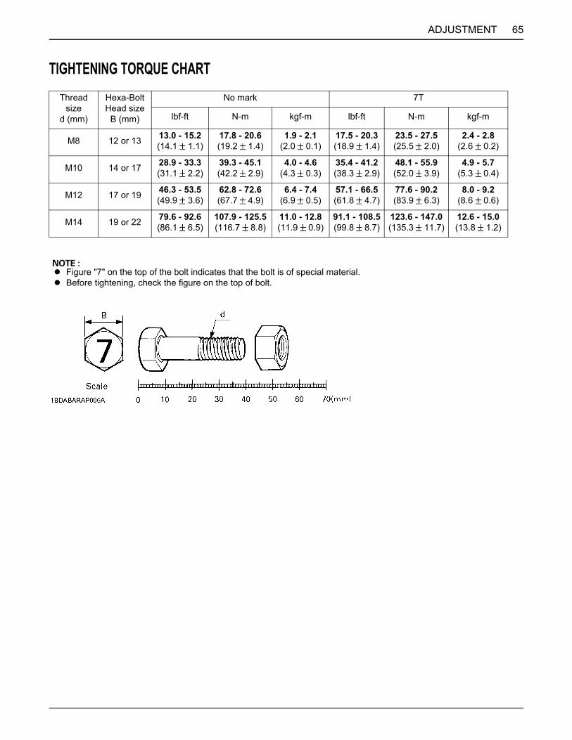
65ADJUSTMENT
TIGHTENING TORQUE CHARTThread
sized (mm)
Hexa-BoltHead size
B (mm)
No mark 7T
lbf-ft N-m kgf-m lbf-ft N-m kgf-m
M8 12 or 13 13.0 - 15.2(14.1 1.1)
17.8 - 20.6(19.2 1.4)
1.9 - 2.1(2.0 0.1)
17.5 - 20.3(18.9 1.4)
23.5 - 27.5(25.5 2.0)
2.4 - 2.8(2.6 0.2)
M10 14 or 17 28.9 - 33.3(31.1 2.2)
39.3 - 45.1(42.2 2.9)
4.0 - 4.6(4.3 0.3)
35.4 - 41.2(38.3 2.9)
48.1 - 55.9(52.0 3.9)
4.9 - 5.7(5.3 0.4)
M12 17 or 19 46.3 - 53.5(49.9 3.6)
62.8 - 72.6(67.7 4.9)
6.4 - 7.4(6.9 0.5)
57.1 - 66.5(61.8 4.7)
77.6 - 90.2(83.9 6.3)
8.0 - 9.2(8.6 0.6)
M14 19 or 22 79.6 - 92.6(86.1 6.5)
107.9 - 125.5(116.7 8.8)
11.0 - 12.8(11.9 0.9)
91.1 - 108.5(99.8 8.7)
123.6 - 147.0(135.3 11.7)
12.6 - 15.0(13.8 1.2)
A Figure "7" on the top of the bolt indicates that the bolt is of special material.A Before tightening, check the figure on the top of bolt.
66 STORAGE
STORAGE
To avoid serious injury:A To reduce fire hazards, allow the engine and
exhaust system to cool before storing themachine in an enclosed space or nearcombustible materials.
A To avoid the danger of exhaust fumepoisoning, do not operate the engine in aclosed building without proper ventilation.
A Do not clean the machine with engine running.A To avoid fire hazards, Do not leave grass and
leaves in the mower and the grass catcher.A When storing, remove the key from the key
switch to avoid operation by unauthorizedpersons.
When the machine will not be operated for over 2 months,clean the machine and perform the following operationsbefore storage.1. Repair parts as necessary.2. Check bolts and nuts and tighten as necessary.3. Apply grease or engine oil to parts most likely to rust.4. Inflate the tires to a little above the standard pressure
levels. (Approximately 110%)5. Lower the mower to the ground.6. Remove the battery from the machine, recharge it,
adjust the electrolyte to the proper level, and store in acool dry place.The battery discharges over time even while instorage. Recharge it once a month in hot seasons andonce every 2 months in cold seasons.
7. Drain fuel tank, fuel lines, and carburetor, or use a fuelstabilizer, to prevent deterioration of the gasoline. Ifyou choose to use a fuel stabilizer, follow themanufacturers recommendations, and add the correctamount for the capacity of the fuel system. Fill the fueltank with clean, fresh gasoline. Run the engine for 2 to3 minutes to get stabilized fuel into the carburetor.
8. Store the machine where it is dry and sheltered fromrain. Cover the machine with a vinyl tarp.
9. Moisture content in most grasses can damage themower and grass catcher if these components are notproperly cleaned after use.Make sure the mower and the grass catcher are cleanand completely empty before storage.
1. Check the tire inflation pressure and adjust asrequired.
2. Install the battery. Before installing the battery, be sureit is fully charged.
3. Do daily checking. (See "DAILY CHECK" in"PERIODIC SERVICE" section.)
4. Check all fluid levels. (engine oil, hydrostatic oil)5. Start the engine. Shut the engine off and walk around
the machine and make a visual inspection looking forevidence of oil or other fluids.
6. Run engine a couple of minutes before you put engineunder load.
REMOVING THE MOWER FROM STORAGE
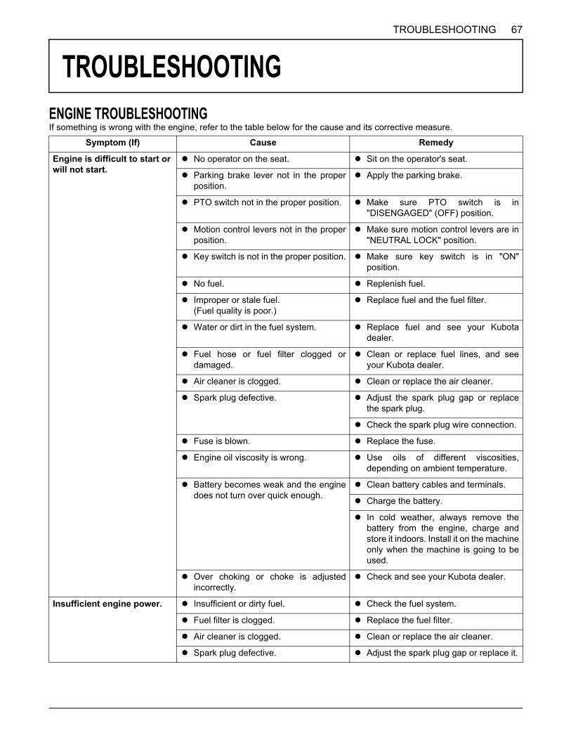
67TROUBLESHOOTING
TROUBLESHOOTING
ENGINE TROUBLESHOOTINGIf something is wrong with the engine, refer to the table below for the cause and its corrective measure.Symptom (If) Cause Remedy
Engine is difficult to start or will not start.
A No operator on the seat. A Sit on the operator's seat.
A Parking brake lever not in the properposition.
A Apply the parking brake.
A PTO switch not in the proper position. A Make sure PTO switch is in"DISENGAGED" (OFF) position.
A Motion control levers not in the properposition.
A Make sure motion control levers are in"NEUTRAL LOCK" position.
A Key switch is not in the proper position. A Make sure key switch is in "ON"position.
A No fuel. A Replenish fuel.
A Improper or stale fuel.(Fuel quality is poor.)
A Replace fuel and the fuel filter.
A Water or dirt in the fuel system. A Replace fuel and see your Kubotadealer.
A Fuel hose or fuel filter clogged ordamaged.
A Clean or replace fuel lines, and seeyour Kubota dealer.
A Air cleaner is clogged. A Clean or replace the air cleaner.
A Spark plug defective. A Adjust the spark plug gap or replacethe spark plug.
A Check the spark plug wire connection.
A Fuse is blown. A Replace the fuse.
A Engine oil viscosity is wrong. A Use oils of different viscosities,depending on ambient temperature.
A Battery becomes weak and the enginedoes not turn over quick enough.
A Clean battery cables and terminals.
A Charge the battery.
A In cold weather, always remove thebattery from the engine, charge andstore it indoors. Install it on the machineonly when the machine is going to beused.
A Over choking or choke is adjustedincorrectly.
A Check and see your Kubota dealer.
Insufficient engine power. A Insufficient or dirty fuel. A Check the fuel system.
A Fuel filter is clogged. A Replace the fuel filter.
A Air cleaner is clogged. A Clean or replace the air cleaner.
A Spark plug defective. A Adjust the spark plug gap or replace it.

68 TROUBLESHOOTING
If you have any questions, contact your local KUBOTA Dealer.
Engine stops suddenly. A Insufficient fuel. A Refuel.A Check the fuel valve position.A Check the carburetor fuel valve
position.
Rough engine running. A Spark plug defective. A Adjust the spark plug gap or replace it.
A Spark plug wire defective. A See your Kubota dealer.
A Carburetion problems. A See your Kubota dealer.
A Ignition coil defective. A See your Kubota dealer.
A Choke is adjusted incorrectly. A See your Kubota dealer.
A Fuel hose or fuel filter clogged ordamaged.
A Clean or replace fuel lines, and seeyour Kubota dealer.
A Improper or stale fuel.(Fuel quality is poor.)
A Replace fuel and the fuel filter.
A Air cleaner is clogged. A Clean or replace the air cleaner.
Exhaust fumes are colored.(Black, Dark or Gray)
A Overload. A Reduce load.
A Low grade fuel is used. A Use specified fuel.
A Fuel filter is clogged. A Replace the fuel filter.
A Air cleaner is clogged. A Clean or replace the air cleanerelement.
A Choke is not fully opened. A Check the choke position.
Exhaust fumes are colored.(White or Blue)
A Excessive engine oil. A Reduce to the specified oil level.
A Piston ring is worn or stuck. A See your Kubota dealer.
Engine overheats. A Engine is overloaded. A Lower speed or reduce load.
A Engine oil is insufficient. A Replenish engine oil.
A Engine air intake screen and coolingfins are dirty.
A Clean the air intake screen and coolingfins.
A Air cleaner element is plugged. A Clean or replace the air cleanerelement.
A Engine speed is too low. A Operate at the "FAST" speed.
A Operating ground speed is too fast. A Operate the machine at the slowerground speed.
Engine knocks. A Stale or low octane fuel. A Use specified fuel.
A Engine overloaded. A Lower ground speed or reduce load.
A Engine speed is too low. A Operate at the "FAST" speed.
Engine will not idle. A Spark plug defective. A Adjust the spark plug gap or replace it.
A Faulty spark plug. A Replace the spark plug.
A Carburetion problem. A See your Kubota dealer.
Symptom (If) Cause Remedy

69TROUBLESHOOTING
BATTERY TROUBLESHOOTING
If you have any questions, contact your local KUBOTA Dealer.
MACHINE TROUBLESHOOTING
If you have any questions, contact your local KUBOTA Dealer.
Symptom (If) Cause Remedy Preventive measure
Starter does not function. A Battery overused untillights are dim.
A Charge batterysufficiently.
A Charge the battery properly.
A Battery has not beenrecharged.
A Poor terminalconnection.
A Clean the terminaland tighten securely.
A Keep the terminal clean andtight.Apply grease and treat withanti-corrosives.
A Battery life expired. A Replace battery.
From beginning starterdoes not function, andlights soon become dim.
A Insufficient charging. A Charge batterysufficiently.
A Battery must be servicedproperly before initial use.
When viewed from top,the top of plates lookwhitish.
A Battery was used withan insufficient amountof electrolyte.
A Add distilled waterand charge thebattery.
A Regularly check theelectrolyte level.
A Battery was used toomuch withoutrecharging.
A Charge batterysufficiently.
A Charge the battery properly.
Recharging is impossible. A Battery life expired. A Replace battery.
Terminals are severelycorroded and heat up.
A Poor terminalconnection.
A Clean the terminaland tighten securely.
A Keep the terminal clean andtight.Apply grease and treat withanti-corrosives.
Battery electrolyte leveldrops rapidly.
A There is a crack or pinholes in the electrolyticcells.
A Replace battery.
A Charging systemtrouble.
A Contact your localKUBOTA Dealer.
Symptom (If) Cause Remedy
Machine operation is notsmooth.
A Hydrostatic transaxle fluid isinsufficient.
A Replenish oil.
A Filter is clogged. A Replace the filter.
Machine does not move whileengine is running.
A Parking brake is on. A Release the parking brake.
A Transaxle fluid level is insufficient. A Replenish oil.
Machine moves when motioncontrol levers are in "NEUTRAL LOCK" position.(Engine is operated.)
A Hydrostatic lever linkage is notcorrectly adjusted.
A Ask your dealer for hydrostatic leverlinkage adjustment.
A Control linkage pivots are sticking. A Full up and lubricate linkage.

70 TROUBLESHOOTING
MOWER TROUBLESHOOTINGSymptom (If) Cause Remedy
Blade does not rotate. A PTO system is not normal:PTO system malfunctioning.
A See your Kubota Dealer.
A PTO system is normal:Broken mower belt.
A Replace.
Mower belt slipping. A Weaken tension spring. A Replace.
A Worn mower belt. A Replace.
A Mower plugged. A Unplug and clean mower deck.
A Debris in pulleys. A Clean.
Discharge chute plugged.
A Grass too wet. A Wait for grass to dry.
A Grass too long. A Raise cutting height and cut grass twice.
A Cutting too low. A Raise cutting height.
A Engine rpm too low. A Mow at full throttle.
A Ground speed too fast. A Slow down.
Streaking of grass uncut. A Ground speed too fast. A Slow down.
A Engine rpm too low. A Mow at full throttle, check and resetengine rpm.
A Grass too long. A Cut grass twice.
A Blades dull or damaged. A Replace blades or have bladessharpened.
A Debris in mower deck. A Clean mower deck.
Uneven cut. A Mower deck not level. A Level mower deck.
A Ground speed too fast. A Slow down.
A Blades dull. A Have blades sharpened.
A Blades worn or damaged. A Replace blades.
A Low tire inflation. A Add air to correct pressure.
A Anti-scalp rollers not adjusted correctly. A Adjust anti-scalp rollers.
A Wheels pressure not adjusted correctly. A Set both tire pressure to the correctpressure.(See "TIRES" in "TIRES AND WHEELS"section.)
Blades scalping grass. A Cutting height too low. A Raise cutting height.
A Turning speed too fast. A Reduce speed on turns.
A Ridges in terrain. A Change mowing pattern.
A Rough or uneven terrain. A Adjust wheels pressure and anti-scalprollers.
A Anti-scalp rollers not adjusted correctly. A Adjust wheels pressure and anti-scalprollers.
A Bent blade(s). A Replace blade(s).

71TROUBLESHOOTING
If you have any questions, contact your local KUBOTA Dealer.
Excessive vibration. A Debris on mower deck or in pulleys. A Clean mower deck and pulleys.
A Damaged mower belt. A Replace mower belt.
A Damaged pulleys. A Replace pulleys.
A Pulleys out of alignment. A Check pulleys.
A Blades out of balance. A Have blades balanced.
Mower loads down machine.
A Engine rpm too low. A Mow at full throttle, check and resetengine rpm.
A Ground speed too fast. A Slow down.
A Debris wrapped around mower spindles. A Clean mower.
A Front of deck too low. A Adjust mower deck.(See "MOWER DECK LEVEL" in"ADJUSTMENT" section.)
Symptom (If) Cause Remedy
72 INDEX
INDEX
Air Cleaner Element (Z121S, Z125S).............44Air Cleaner Element (Z121S, Z125S).............55Air Cleaner Element (Z122E, Z125E).............37Air Cleaner Element (Z122E, Z125E).............43Air Cleaner Element (Z122E, Z125E).............55Air Intake Screen............................................34Amount of Fuel and Refueling........................33ANTI-SCALP ROLLERS ................................61Battery Condition............................................48Blade ..............................................................56Combustion Chamber ....................................55Electric Clutch Adjustment .............................54Engine Break-in..............................................15Engine Breather Hose ....................................55Engine Oil (Z121S, Z125S) ............................43Engine Oil (Z122E, Z125E) ............................40Engine Oil (Z122E, Z125E) ............................55Engine Oil Filter (Z121S, Z125S) ...................50Engine Oil Filter (Z122E, Z125E) ...................41Engine Oil Filter (Z122E, Z125E) ...................55Engine Oil Level .............................................32Engine Shroud................................................44Engine Start System.......................................39Engine Valve Clearance (Z121S, Z125S) ......54Engine Valve Clearance (Z122E, Z125E) ......55Fuel Filter (Z122E, Z125E).............................55Fuel Gauge.....................................................12Fuel Lines.......................................................46Fuel Lines.......................................................55Fuses..............................................................56Hour Meter .....................................................12HST NEUTRAL ..............................................59Hydraulic Hose ...............................................51Hydraulic Hose ...............................................55Hydrostatic Transaxle Bypass Rods ..............21Immediately Stop the Engine if:......................12Inflation Pressure ...........................................25Inflation Pressure ...........................................34Key Switch......................................................11LEVEL MOWER DECK (Front-to-Rear) .........63LEVEL MOWER DECK (Side-to-Side)...........62Light Switch ....................................................16Lubricating Oil for New Machines...................15Machine Break-in ...........................................15MAXIMUM SPEED (FORWARD)...................60Motion Control Lever ......................................18MOTION CONTROL LEVER ALIGNMENT....60Movable Parts ................................................35Mower Belt Replacement .............................. 58Mower Lift Pedal ............................................ 17Muffler and Spark Arrester (if equipped) ....... 42Muffler and Spark Arrester (if equipped) ....... 55OPC System.................................................. 40Operator's Seat.............................................. 16Parking Brake Lever ...................................... 17Precleaner Element (Except Z125E) ............. 36Precleaner Element (Except Z125E) ............. 43Precleaner Element (Except Z125E) ............. 55PTO Switch.................................................... 23Remove and Install Front Caster Wheels ...... 26Seat Belt ........................................................ 16Spark Plug ..................................................... 45Spark Plug ..................................................... 55Starting .......................................................... 24Throttle Cable ................................................ 49Throttle Lever ................................................ 11Throttle Lever ................................................ 17Tire Pressure ................................................. 34Transaxle Fluid .............................................. 53Transaxle Fluid Level .................................... 35Transaxle Oil Filter Cartridge......................... 52Warm-up and Transmission Oil in the Low Temperature Range ...................................... 13