operator's manual - kubota...kubota corporation is ··· since its inception in 1890, kubota...
TRANSCRIPT

M7040M6040
M8540M9540
MODELS
OPERATOR'S MANUAL
English (Australia)Code No. 3C793-9971-1
M6040·M7040·M8540·M9540
© KUBOTA Corporation 2009PRINTED IN JAPAN
READ AND SAVE THIS MANUAL

KUBOTA Corporation is ···Since its inception in 1890, KUBOTA Corporation has grown to rank as one of the major firms in Japan.
To achieve this status, the company has through the years diversified the range of its products and services to a remarkable extent, until today, 19 plants and 16,000 employees produce over 1,000 different items, large and small.
All these products and all the services which accompany them, however, are unified by one central commitment. KUBOTA makes products which, taken on a national scale, are basic necessities. Products which are indispensable, products intended to help individuals and nations fulfill the potential inherent in their environment. For KUBOTA is the Basic Necessities Giant.
This potential includes water supply, food from the soil and from the sea, industrial development, architecture and construction, transportation.
Thousands of people depend on KUBOTA's know-how, technology, experience and customer service. You too can depend on KUBOTA.
M6040/M7040/M8540/M9540AS . C . 10 - 12 . 2 . AK
FOREWORD
3SAFETY FIRST
IMPORTANT :
NOTE :
3 DANGER :
3 WARNING :
3 CAUTION :
Indicates an imminently hazardous situation which, if not avoided, will result in death or serious injury.
Indicates a potentially hazardous situation which, if not avoided, could result in death or serious injury.
Indicates a potentially hazardous situation which, if not avoided, may result in minor or moderate injury.
Indicates that equipment or property damage could result if instructions are not followed.
Gives helpful information.
Thank you very much for choosing the CAB model of the M series tractor.This operator's Manual covers the operation, inspection and preventive maintenance instructions that is specific to the oceania models. For other information and instructions, refer to the separately issued operator's manual for the sister models. (M6040, M7040, M8540, M9540)Please read both manuals carefully, to operate the machine properly and safety.Proper daily inspection, servicing and lubrication keeps your machine in good condition.
This symbol, the industry's "Safety Alert Symbol", is used throughout this manual and on labels on the machine itself to warn of the possibility of personal injury. Read these instructions carefully. It is essential that you read the instructions and safety regulations before you attempt to assemble or use this unit.

CONTENTS
SAFE OPERATION ............................................................................................ -1SPECIFICATIONS....................................................................................................... 1SPECIFICATION TABLE ......................................................................................... 1TRAVELING SPEEDS ............................................................................................. 3
INSTRUMENT PANEL AND CONTROLS................................................................... 4
OPERATING THE TRACTOR................................................................................... 10STARTING............................................................................................................. 10
Operator's Seat...............................................................................................................10Light Switch ....................................................................................................................11Turn Signal / Hazard Light Switch ..................................................................................11With Trailer Connector....................................................................................................11
PTO RPM / TRAVEL SPEED MONITOR............................................................... 12PTO Speed Display Mode Switching..............................................................................12
PARKING............................................................................................................... 13Parking Brake Lever .......................................................................................................13Gear Locked Parking Lever ............................................................................................13
OPERATING TECHNIQUES ................................................................................. 14Trailer Electrical Outlet ...................................................................................................14
PTO ........................................................................................................................... 15PTO OPERATION.................................................................................................. 15
PTO Gear Shift Lever .....................................................................................................15PTO Clutch Control Lever...............................................................................................15PTO Clutch Control Switch .............................................................................................16LCD Monitor Message....................................................................................................17
3-POINT HITCH & DRAWBAR.................................................................................. 183-POINT HITCH..................................................................................................... 18
Remote Hitch UP / DOWN Lever....................................................................................18DRAWBAR............................................................................................................. 18
Adjusting Drawbar Length ..............................................................................................18Swing Drawbar ...............................................................................................................19
HYDRAULIC UNIT..................................................................................................... 20REMOTE HYDRAULIC CONTROL SYSTEM........................................................ 20
Remote Control Valve.....................................................................................................20Remote Control Valve Lever...........................................................................................20
TIRES, WHEELS AND BALLAST.............................................................................. 22TIRES..................................................................................................................... 22
Inflation Pressure............................................................................................................22Dual Tires .......................................................................................................................22
WHEEL ADJUSTMENT ......................................................................................... 22Front Wheels (with 4 wheel drive) ..................................................................................23Rear Wheels ...................................................................................................................24
MAINTENANCE......................................................................................................... 25

CONTENTS
SERVICE INTERVALS .......................................................................................... 25
PERIODIC SERVICE................................................................................................. 28EVERY 100 HOURS.............................................................................................. 28
Adjusting Parking Brake Lever .......................................................................................28Checking Gear Locked Parking Lever ............................................................................28
SERVICE AS REQUIRED...................................................................................... 28Replacing Fuse...............................................................................................................28Replacing Light Bulb.......................................................................................................30
OPTIONS................................................................................................................... 31

-1SAFE OPERATION
SAFE OPERATION
Careful operation is your best insurance against anaccident.Read and understand this manual carefully beforeoperating the tractor.All operators, no matter how much experience they mayhave, should read this and other related manuals beforeoperating the tractor or any implement attached to it. It isthe owner's obligation to instruct all operators in safeoperation.1. Know your equipment and its limitations. Read thisentire manual before attempting to start and operatethe tractor.
2. Pay special attention to the danger, warning andcaution labels on the tractor.
3. KUBOTA recommends the use of a CAB or Roll OverProtective Structures (ROPS) and seat belt in almostall applications. This combination will reduce the riskof serious injury or death, should the tractor be upset.If the CAB or ROPS is loosened or removed for anyreason, make sure that all parts are reinstalledcorrectly before operating the tractor.Never modify or repair a CAB or ROPS becausewelding, bending, drilling, grinding, or cutting mayweaken the structure.A damaged CAB or ROPS structure must be replaced,not repaired or revised. If any structural member of theCAB or ROPS is damaged, replace the entire structureat your local KUBOTA Dealer.
4. Always use the seat belt if the tractor has a CAB orROPS. Do not use the seat belt if there is no CAB orROPS. Check the seat belt regularly and replace iffrayed or damaged.
5. Do not operate the tractor or any implement attachedto it while under the influence of alcohol, medication,controlled substances or while fatigued.
6. Carefully check the vicinity before operating tractor orany implement attached to it. Check for overheadclearance which may interfere with a CAB or ROPS.Do not allow any bystanders around or near tractorduring operation.
7. Before allowing other people to use your tractor,explain how to operate and have them read thismanual before operation.
8. Never wear loose, torn, or bulky clothing aroundtractor. It may catch on moving parts or controls,leading to the risk of an accident. Use additional safetyitems, e.g. hard hat, safety boots or shoes, eye andhearing protection, gloves, etc., as appropriate orrequired.
9. Do not allow passengers to ride on any part of thetractor at anytime. The operator must remain in thetractor seat during operation.
10.Check brakes, clutch, linkage pins and othermechanical parts for improper adjustment and wear.Replace worn or damaged parts promptly. Check thetightness of all nuts and bolts regularly. (For furtherdetails, see "MAINTENANCE" section.)
11.Keep your tractor clean. Dirt, grease, and trash buildup may contribute to fires and lead to personal injury.
12.Use only implements meeting the specifications listedunder "IMPLEMENT LIMITATIONS" in this manual orimplements approved by KUBOTA.
13.Use proper weights on the front or rear of the tractor toreduce the risk of upsets. When using the front loader,put an implement or ballast on the 3-point hitch toimprove stability. Follow the safe operatingprocedures specified in the implement or attachmentmanual.
1. BEFORE OPERATING THE TRACTOR
(1) Seat belt

SAFE OPERATION-2
14. The narrower the tread, the greater the risk of a tractorupset. For maximum stability, adjust the wheels to thewidest practical tread width for your application. (See"TIRES, WHEELS AND BALLAST" section.)
15.Do not modify the tractor. Unauthorized modificationmay affect the function of the tractor, which may resultin personal injury.
Operator safety is a priority. Safe operation, specificallywith respect to overturning hazards, entails understandingthe equipment and environmental conditions at the time ofuse. Some prohibited uses which can affect overturninghazards include traveling and turning with implementsand loads carried too high etc. This manual sets forthsome of the obvious risks, but the list is not, and cannotbe, exhaustive. It is the operator's responsibility to be alertfor any equipment or environmental condition that couldcompromise safe operation.
C Starting1. Always sit in the operator's seat when starting engine
or operating levers or controls. Adjust seat perinstructions in the operating the tractor section. Neverstart engine while standing on the ground.
2. Before starting the engine, make sure that all levers(including auxiliary control levers) are in their neutralpositions, that the parking brake is engaged, and thatboth the clutch and the Power Take-Off (PTO) aredisengaged or "OFF".Fasten the seat belt if the tractor has a CAB, a fixedROPS or a foldable ROPS in the upright and lockedposition.
3. Do not start engine by shorting across starterterminals or bypassing the safety start switch.Machine may start in gear and move if normal startingcircuitry is bypassed.
4. Do not operate or idle engine in a non-ventilated area.Carbon monoxide gas is colorless, odorless, anddeadly.
5. Check before each use that operator presencecontrols are functioning correctly. Test safety systems.(See "Checking Engine Start System" in "EVERY 50HOURS" in "PERIODIC SERVICE" section.)Do not operate unless they are functioning correctly.
C Working1. Pull only from the drawbar. Never hitch to axle housing
or any other point except drawbar; such arrangementswill increase the risk of serious personal injury or deathdue to a tractor upset.
2. Keep all shields and guards in place. Replace any thatare missing or damaged.
3. Avoid sudden starts. To avoid upsets, slow downwhen turning, on uneven ground, and before stopping.
4. The tractor cannot turn with the rear wheel or 4-wheeldifferential locked and attempting to do so could bedangerous.
5. Do not operate near ditches, holes, embankments, orother ground surface features which may collapseunder the tractor's weight. The risk of tractor upset iseven higher when the ground is loose or wet. Tallgrass can hide obstacles, walk the area first to be sure.
6. Watch where you are going at all times. Watch for andavoid obstacles. Be alert at row ends, near trees, andother obstructions.
7. When working in groups, always let the others knowwhat you are going to do before you do it.
8. Never try to get on or off a moving tractor. 9. Do not stand between tractor and implement or trailed
vehicle unless parking brake is applied.
C Safety for childrenTragedy can occur if the operator is not alert to thepresence of children. Children generally are attracted tomachines and the work they do.1. Never assume that children will remain where you last
saw them.2. Keep children out of the work area and under the
watchful eye of another responsible adult.3. Be alert and shut your machine down if children enter
the work area.
(1) Rear wheels (A) Tread Width
2. OPERATING THE TRACTOR (1) Drawbar

-3SAFE OPERATION
4. Never carry children on your machine. There is no safeplace for them to ride. They may fall off and be runover or interfere with your control of the machine.
5. Never allow children to operate the machine evenunder adult supervision.
6. Never allow children to play on the machine or on theimplement.
7. Use extra caution when backing up. Look behind anddown to make sure area is clear before moving.
8. When parking your machine if at all possible park on afirm, flat and level surface; if not, park across a slope.Set the parking brake(s), lower the implements to theground, remove the key from the ignition and lock thecab door (if equipped) and chock the wheels.
C Operating on slopesSlopes are a major factor related to loss-of-control and tip-over accidents, which can result in severe injury or death.All slopes require extra caution. 1. To avoid upsets, always back up steep slopes. If you
cannot back up the slope or if you feel uneasy on it, donot operate on it. Stay off slopes too steep for safeoperation.
2. Driving forward out of a ditch, mired condition or up asteep slope increases the risk of a tractor to be upsetbackward. Always back out of these situations. Extracaution is required with 4-wheel drive models becausetheir increased traction can give the operator falseconfidence in the tractor's ability to climb slopes.
3. Keep all movement on slopes slow and gradual. Donot make sudden changes in speed, direction or applybrake and make sudden motions of the steeringwheel.
4. Avoid disengaging the clutch or changing gears speedwhen climbing or going down a slope. If on a slopedisengaging the clutch or changing gears to neutralcould cause loss of control.
5. Special attention should be made to the weight andlocation of implements and loads as such will affect thestability of the tractor.
6. To improve stability on slope, set widest wheel treadas shown in "TIRES, WHEELS AND BALLAST"section.Follow recommendations for proper ballasting.
C Driving the tractor on the road 1. Lock the 2 brake pedals together to help assure
straight-line stops. Uneven braking at road speedscould cause the tractor to tip over.
2. Check the front wheel engagement. The brakingcharacteristics are different between 2 and 4-wheeldrive. Be aware of the difference and use carefully.
3. Always slow the tractor down before turning. Turningat high speed may tip the tractor over.
4. Turn the headlights on. Dim them when meetinganother vehicle.
5. Drive at speeds that allow you to maintain control at alltimes.
6. Do not apply the differential lock while traveling at roadspeeds. The tractor may run out of control.
7. Avoid sudden motions of the steering wheel as theycan lead to a dangerous loss of stability. The risk isespecially great when the tractor is traveling at roadspeeds.
8. Do not operate an implement while the tractor is on theroad. Lock the 3-point hitch in the raised position.
1. Disengage the PTO, lower all implements to theground, place all control levers in their neutralpositions, set the parking brake, stop the engine, andremove the key.
2. Make sure that the tractor has come to a completestop before dismounting.
3. Avoid parking on steep slopes, if at all possible park ona firm and level surface; if not, park across a slope withchock the wheels.Failure to comply with this warning may allow thetractor to move and could cause injury or death.
(1) Brake Pedal (LH)(2) Brake Pedal (RH)(3) Brake Pedal Lock
(A) Whenever travelling on the road
3. PARKING THE TRACTOR
SAFE OPERATION-4
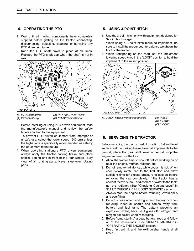
1. Wait until all moving components have completelystopped before getting off the tractor, connecting,disconnecting, adjusting, cleaning, or servicing anyPTO driven equipment.
2. Keep the PTO shaft cover in place at all times.Replace the PTO shaft cap when the shaft is not inuse.
3. Before installing or using PTO driven equipment, readthe manufacturer's manual and review the safetylabels attached to the equipment.To prevent PTO driven equipment from improper orunsafe use, select the lower speed (540rpm) unlessthe higher one is specifically recommended as safe bythe equipment manufacture.
4. When operating stationary PTO driven equipment,always apply the tractor parking brake and placechocks behind and in front of the rear wheels. Stayclear of all rotating parts. Never step over rotatingparts.
1. Use the 3-point hitch only with equipment designed for3-point hitch usage.
2. When using a 3-point hitch mounted implement, besure to install the proper counterbalance weight on thefront of the tractor.
3. When transporting on the road, set the implementlowering speed knob in the "LOCK" position to hold theimplement in the raised position.
Before servicing the tractor, park it on a firm, flat and levelsurface, set the parking brake, lower all implements to theground, place the gear shift lever in neutral, stop theengine and remove the key. 1. Allow the tractor time to cool off before working on or
near the engine, muffler, radiator, etc. 2. Do not remove radiator cap while coolant is hot. When
cool, slowly rotate cap to the first stop and allowsufficient time for excess pressure to escape beforeremoving the cap completely. If the tractor has acoolant recovery tank, add coolant or water to the tank,not the radiator. (See "Checking Coolant Level" in"DAILY CHECK" in "PERIODIC SERVICE" section.)
3. Always stop the engine before refueling. Avoid spillsand overfilling.
4. Do not smoke when working around battery or whenrefueling. Keep all sparks and flames away frombattery and fuel tank. The battery presents anexplosive hazard, because it gives off hydrogen andoxygen especially when recharging.
5. Before "jump starting" a dead battery, read and followall of the instructions. (See "JUMP STARTING" in"OPERATING THE ENGINE" section.)
6. Keep first aid kit and fire extinguisher handy at alltimes.
4. OPERATING THE PTO
(1) PTO Shaft cover(2) PTO Shaft cap
(A) "NORMAL POSITION"(B) "RAISED POSITION"
5. USING 3-POINT HITCH
(1) 3-point hitch lowering speed knob (A) "FAST"(B) "SLOW"(C) "LOCK"
6. SERVICING THE TRACTOR

-5SAFE OPERATION
7. Disconnect the battery's ground cable before workingon or near electric components.
8. To avoid the possibility of battery explosion, do not useor charge the refillable type battery if the fluid level isbelow the LOWER ( lower limit level ) mark. Check thefluid level regularly and add distilled water as requiredso that the fluid level is between the UPPER andLOWER levels.
9. To avoid sparks from an accidental short circuit,always disconnect the battery's ground cable (-) firstand reconnect it last.
10.Do not attempt to mount a tire on a rim. This should bedone by a qualified person with the proper equipment.
11.Always maintain the correct tire pressure. Do notinflate tires above the recommended pressure shownin the operator's manual.
12.Securely support the tractor when either changingwheels or adjusting the wheel tread width.
13.Make sure that wheel bolts have been tightened to thespecified torque.
14.Do not work under any hydraulically supporteddevices. They can settle, suddenly leak down, or beaccidentally lowered. If it is necessary to work undertractor or any machine elements for servicing oradjustment, securely support them with stands orsuitable blocking beforehand.
15.Escaping hydraulic fluid under pressure has sufficientforce to penetrate skin, causing serious personalinjury. Before disconnecting hydraulic lines, be sure torelease all residual pressure. Before applyingpressure to the hydraulic system, make sure that allconnections are tight and that all lines, pipes, andhoses are free of damage.
16.Fluid escaping from pinholes may be invisible. Do notuse hands to search for suspected leaks; use a pieceof cardboard or wood. Use of safety goggles or othereye protection is also highly recommended. If injuredby escaping fluid, see a medical doctor at once. Thisfluid will produce gangrene or severe allergic reaction.
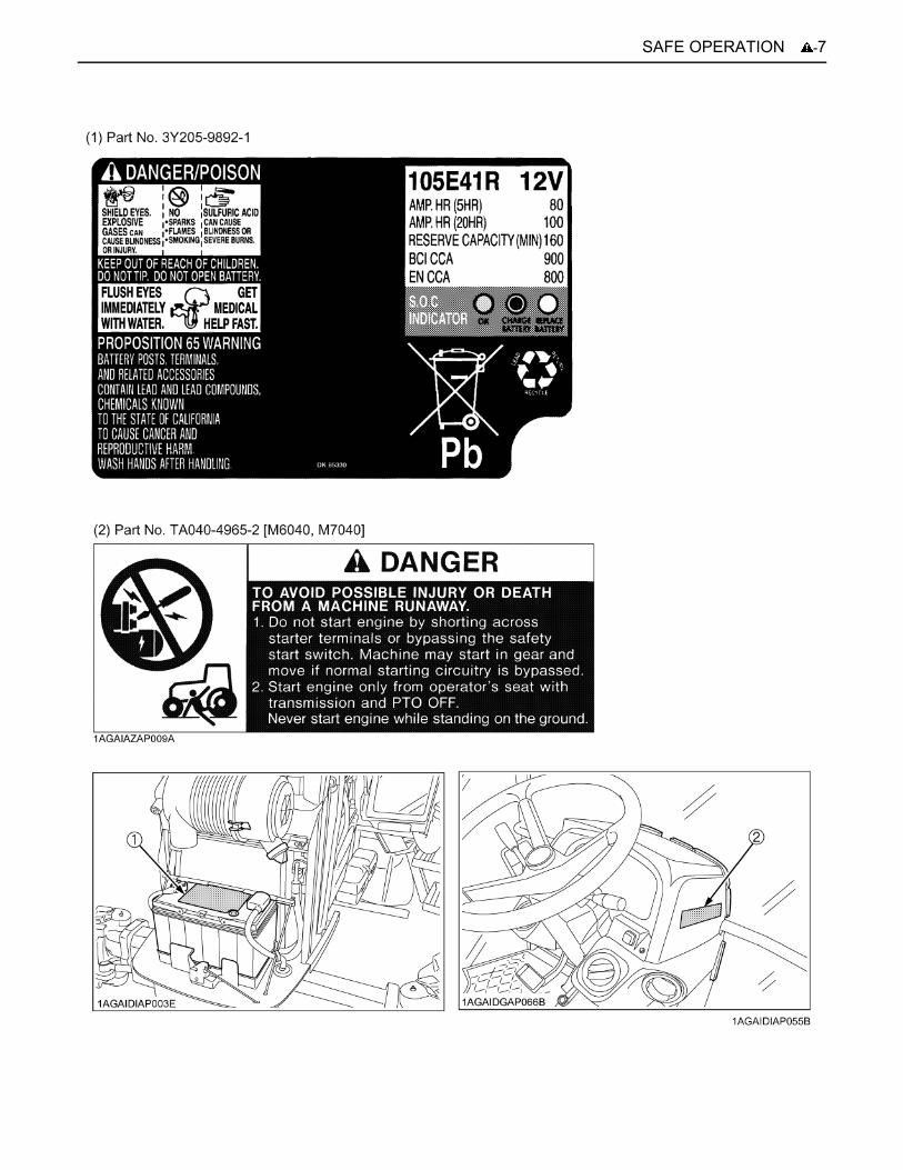
(1) Battery
(1) Cardboard(2) Hydraulic line(3) Magnifying glass

SAFE OPERATION-6
7. DANGER, WARNING AND CAUTION LABELS
-7SAFE OPERATION

SAFE OPERATION-8
-9SAFE OPERATION
SAFE OPERATION-10
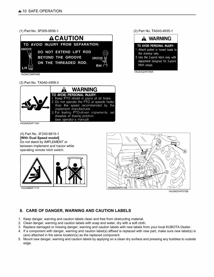
1. Keep danger, warning and caution labels clean and free from obstructing material.2. Clean danger, warning and caution labels with soap and water, dry with a soft cloth.3. Replace damaged or missing danger, warning and caution labels with new labels from your local KUBOTA Dealer.4. If a component with danger, warning and caution label(s) affixed is replaced with new part, make sure new label(s) is
(are) attached in the same location(s) as the replaced component.5. Mount new danger, warning and caution labels by applying on a clean dry surface and pressing any bubbles to outside
edge.
8. CARE OF DANGER, WARNING AND CAUTION LABELS

1SPECIFICATIONS
SPECIFICATIONS
SPECIFICATION TABLEModelM6040 M7040 M8540 M9540
4WD 2WD 4WD 4WD 4WD
Engine
Model V3307-DI V3800-DI-T [V3800-DI-TE3]
Type Direct Injection, liquid cooled 4 cylinder diesel
Number of cylinders 4
Total displacement cm 3331 3769
Bore and stroke mm 94 x 120 100 x 120
Rated speed rpm 2600
Net power *1 kW 46.2 50.7 62.6 70.8
PTO power *1 (factory observed) kW 41.0 46.2 56.0 62.7
Maximum torque N-m /rpm
213 / 1300 to 1500
232 / 1300 to 1500
283 / 1400 to 1600
316 / 1400 to 1600
[314 / 1500 to 1700]
Battery capacity 12V, RC: 160 min, CCA 900A
Fuel Diesel fuel No.1 (below-10 ),Diesel fuel No.2 (above-10 )
Fuel tank capacity L 90 110
Engine oil capacity L 11 10.7
Coolant capacity L 8 9.0
Dimensions
Overall length mm 3505 3625 3505 3760 [3955]
Overall width(minimum tread) mm 1860 2010
Overall height mm 2555 2565 2570 [2650]
Wheel base mm 2110 2145 2110 2250
TreadFront mm
1420, 1440, 1520
1420 to
1820
1420, 1440,1520
1540, 1560, 1600[1540, 1560, 1660]
Rear mm 1420 to 1720 1540 to 1940[1498, 1598, 1698, 1798, 1898]
Minimum ground clearance mm 430
(Fuel tank stay)440
(Fuel tank stay)450
(Drawbar bracket)
Weight kg 2430 2380 2440 2800
2 SPECIFICATIONS
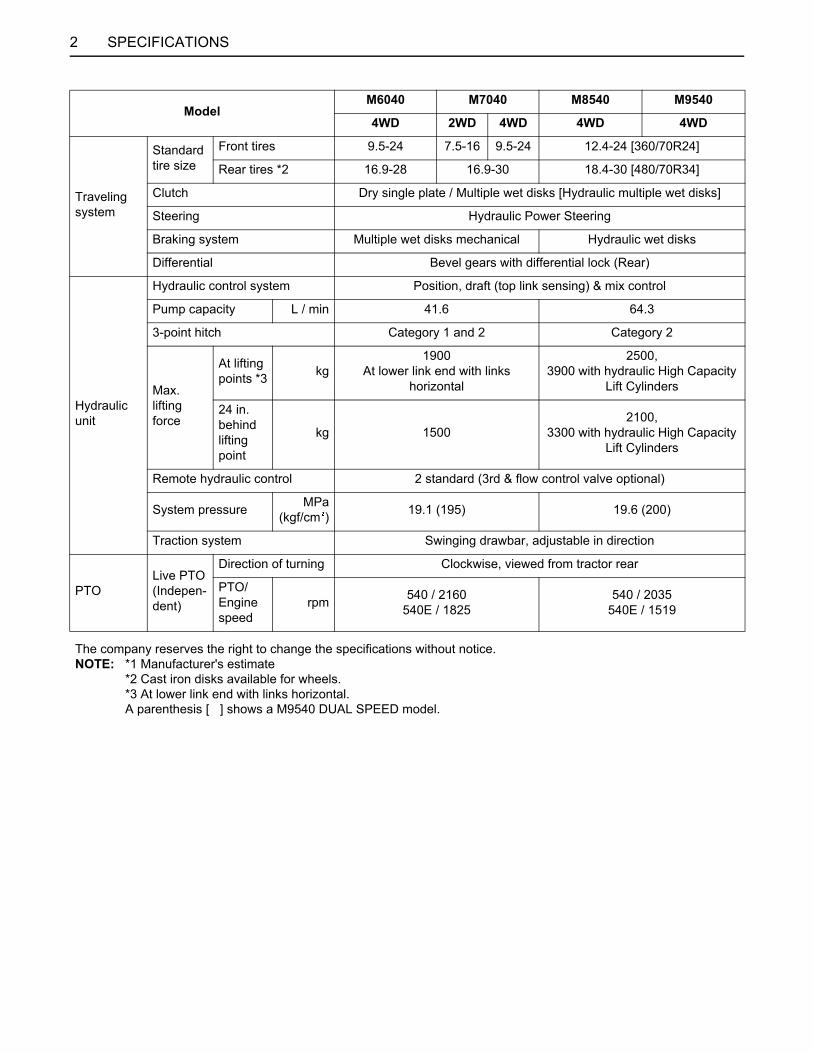
Traveling system
Standardtire size
Front tires 9.5-24 7.5-16 9.5-24 12.4-24 [360/70R24]
Rear tires *2 16.9-28 16.9-30 18.4-30 [480/70R34]
Clutch Dry single plate / Multiple wet disks [Hydraulic multiple wet disks]
Steering Hydraulic Power Steering
Braking system Multiple wet disks mechanical Hydraulic wet disks
Differential Bevel gears with differential lock (Rear)
Hydraulic unit
Hydraulic control system Position, draft (top link sensing) & mix control
Pump capacity L / min 41.6 64.3
3-point hitch Category 1 and 2 Category 2
Max. lifting force
At liftingpoints *3 kg
1900At lower link end with links
horizontal
2500, 3900 with hydraulic High Capacity
Lift Cylinders
24 in. behind lifting point
kg 15002100,
3300 with hydraulic High Capacity Lift Cylinders
Remote hydraulic control 2 standard (3rd & flow control valve optional)
System pressure MPa(kgf/cm ) 19.1 (195) 19.6 (200)
Traction system Swinging drawbar, adjustable in direction
PTOLive PTO(Indepen-dent)
Direction of turning Clockwise, viewed from tractor rear
PTO/Engine speed
rpm 540 / 2160540E / 1825
540 / 2035540E / 1519
The company reserves the right to change the specifications without notice.NOTE: *1 Manufacturer's estimate
*2 Cast iron disks available for wheels.*3 At lower link end with links horizontal.A parenthesis [ ] shows a M9540 DUAL SPEED model.
ModelM6040 M7040 M8540 M9540
4WD 2WD 4WD 4WD 4WD

3SPECIFICATIONS
TRAVELING SPEEDS(At rated engine rpm)
Model M6040 M7040 M8540 / M9540 M9540Tire size (Rear) 16.9-28 16.9-30 18.4-30 480/70R34
Transmission type without Dual speed with Dual speedHi Lo
Shuttleshift lever
Range gearshift lever
Main gearshift lever
km/h km/h km/h km/h km/h
CREEP
1 0.34 0.35 0.42 0.46 0.392 0.48 0.50 0.54 0.59 0.503 0.64 0.67 0.71 0.78 0.654 1.0 1.1 0.91 0.99 0.845 --- --- 1.12 1.23 1.046 --- --- 1.35 1.48 1.25
L
1 2.4 2.5 2.6 3.0 2.52 3.4 3.5 3.4 3.8 3.23 4.5 4.7 4.5 5.0 4.24 7.4 7.7 5.7 6.4 5.45 --- --- 7.1 8.0 6.76 --- --- 8.5 9.6 8.1
H
1 9.3 9.6 10.4 11.5 9.62 13.1 13.6 13.4 14.7 12.43 17.6 18.2 17.7 19.4 16.34 28.6 29.7 22.6 24.8 20.95 --- --- 28.0 30.8 25.96 --- --- 33.7 37.0 31.1
CREEP
1 0.34 0.36 0.42 0.46 0.392 0.49 0.51 0.53 0.60 0.503 0.65 0.68 0.70 0.79 0.664 1.1 1.1 0.90 1.01 0.855 --- --- 1.11 1.25 1.056 --- --- 1.34 1.50 1.26
L
1 2.4 2.5 2.6 3.0 2.52 3.4 3.6 3.4 3.9 3.33 4.6 4.8 4.4 5.1 4.34 7.5 7.8 5.7 6.5 5.55 --- --- 7.0 8.1 6.86 --- --- 8.5 9.7 8.2
H
1 9.4 9.7 10.4 11.6 9.82 13.3 13.8 13.3 14.9 12.53 17.8 18.5 17.5 19.6 16.54 29.0 30.1 22.5 25.1 21.15 --- --- 27.8 31.1 26.26 --- --- 33.4 37.5 31.5
The company reserves the right to change the specifications without notice

4 INSTRUMENT PANEL AND CONTROLS
INSTRUMENT PANEL AND CONTROLS
B Instrument Panel, Switches and Hand ControlsILLUSTRATED CONTENTS(1) Hydraulic-shuttle shift lever [Hydraulic shuttle model] ............................
D
(1) Synchro-shuttle shift lever [Synchro shuttle model] ..............................
D
(2) Clutch pedal ............................................... D
(3) Tilt pedal .................................................... D
(4) Turn signal / Head light switch .................... 11, 11
(5) Hazard light switch ..................................... 11
(6) Horn button ................................................ D
(7) Key switch ................................................. D
(8) Foot throttle ............................................... D
(9) Brake pedal ............................................... D
D See operator's manual issued separately for the sister model. [M6040, M7040, M8540, M9540]

5INSTRUMENT PANEL AND CONTROLS
A Only the M9540 dual speed model is equipped with an indicator (2) (3) (11) (12) and (13).A Air cleaner indicator (11)
If the air cleaner clogged, the warning lamp in the Easy Checker(TM) will come on.If this should happen during operation, clean the air cleaner element.(See "Cleaning Air Cleaner Primary Element" in "EVERY 100 HOURS" in "PERIODIC SERVICE" section.)
ILLUSTRATED CONTENTS ILLUSTRATED CONTENTS(1) Hazard / Turn signal indicator .................... 11 (10) Heater indicator ....................................... D
(2) High beam indicator ................................... --- (11) Air cleaner indicator ................................. ---(3) Trailer indicator .......................................... 11 (12) Rear wheel differential lock indicator ........ D
(4) PTO clutch indicator .................................. 15, 16 (13) Parking brake indicator ............................ 13
(5) Liquid crystal display .................................. D (14) Fuel level indicator ................................... D
(6) Electrical charge indicator .......................... D (15) Fuel gauge ............................................... D
(7) Engine oil pressure indicator ...................... D (16) Coolant temperature gauge ..................... D
(8) Tachometer ............................................... D (17) PTO / Hour meter select switch ................ D
(9) 4WD indicator ............................................ D (18) Travel speed select switch ....................... D

6 INSTRUMENT PANEL AND CONTROLS
B Foot and Hand Controls
ILLUSTRATED CONTENTS
(1) Tool box ................................................................... ---
(2) Differential lock pedal .............................................. D(3) Operator's seat ........................................................ D(4) Front wheel drive lever ............................................. D(5) Seat belt .................................................................. D(6) Cup holder ............................................................... ---
(7) 3-Point hitch lowering speed knob ........................... D(8) Parking brake lever .................................................. D(9) Hand throttle lever ................................................... D(10) Range gear shift lever ............................................ D(11) Main gear shift lever ............................................... D(12) Remote control valve lever .................................... 20
(13) Position control lever ............................................. D(14) Draft control lever .................................................. D(15) PTO clutch control lever ......................................... 15
(16) Cigarette lighter ..................................................... D(17) Electrical outlet ...................................................... D(18) Trailer electrical outlet ............................................ 14
(19) Remote control valve coupler ................................ D(20) PTO gear shift lever ............................................... 15
7INSTRUMENT PANEL AND CONTROLS
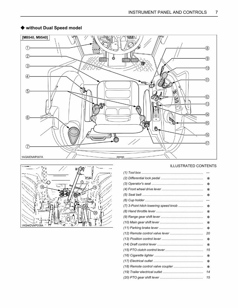
C without Dual Speed model
ILLUSTRATED CONTENTS
(1) Tool box ................................................................... ---
(2) Differential lock pedal .............................................. D(3) Operator's seat ........................................................ D(4) Front wheel drive lever ............................................. D(5) Seat belt .................................................................. D(6) Cup holder ............................................................... ---
(7) 3-Point hitch lowering speed knob ........................... D(8) Hand throttle lever ................................................... D(9) Range gear shift lever .............................................. D(10) Main gear shift lever ............................................... D(11) Parking brake lever ................................................ D(12) Remote control valve lever .................................... 20
(13) Position control lever ............................................. D(14) Draft control lever .................................................. D(15) PTO clutch control lever ......................................... 15
(16) Cigarette lighter ..................................................... D(17) Electrical outlet ...................................................... D(18) Remote control valve coupler ................................ D(19) Trailer electrical outlet ............................................ 14
(20) PTO gear shift lever ............................................... 15
8 INSTRUMENT PANEL AND CONTROLS
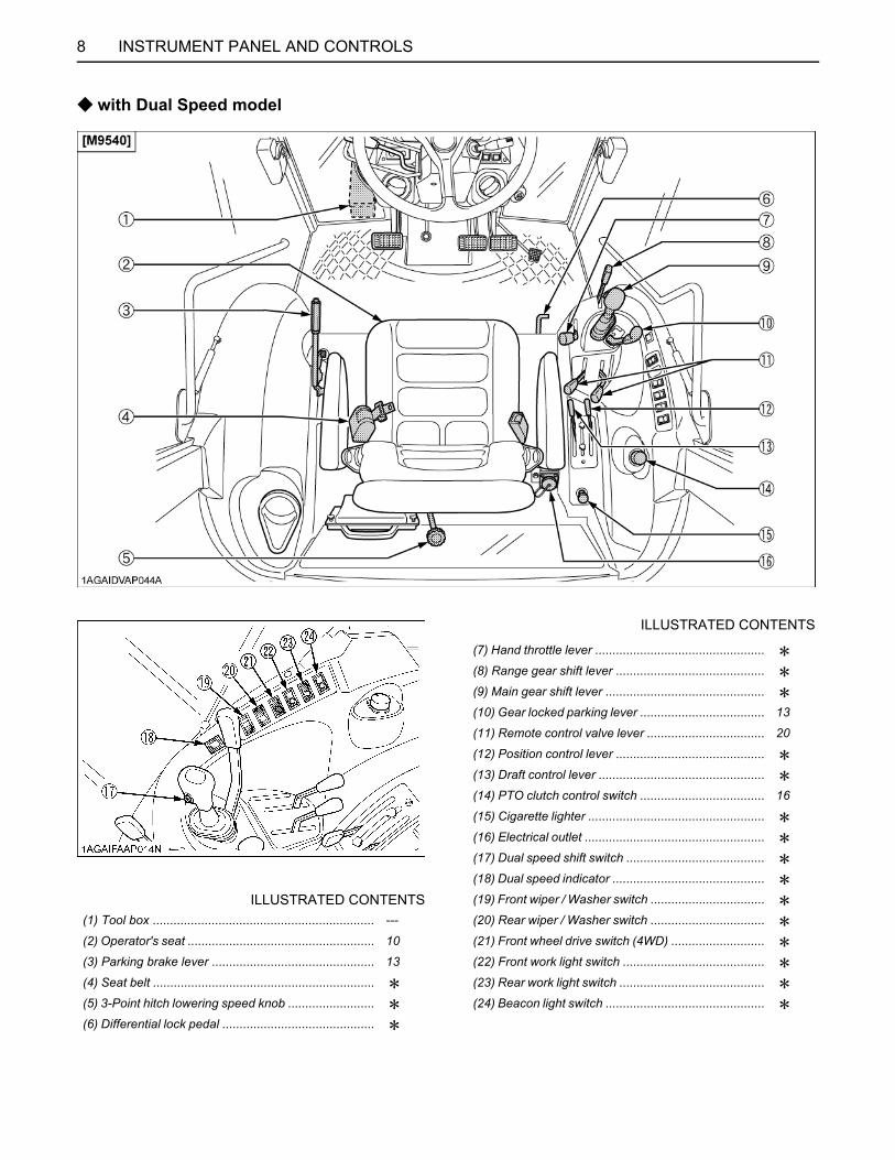
C with Dual Speed model
ILLUSTRATED CONTENTS
(7) Hand throttle lever ................................................. D(8) Range gear shift lever ........................................... D(9) Main gear shift lever .............................................. D(10) Gear locked parking lever .................................... 13
(11) Remote control valve lever .................................. 20
(12) Position control lever ........................................... D(13) Draft control lever ................................................ D(14) PTO clutch control switch .................................... 16
(15) Cigarette lighter ................................................... D(16) Electrical outlet .................................................... D(17) Dual speed shift switch ........................................ D(18) Dual speed indicator ............................................ D
ILLUSTRATED CONTENTS (19) Front wiper / Washer switch ................................. D(1) Tool box ................................................................ --- (20) Rear wiper / Washer switch ................................. D(2) Operator's seat ...................................................... 10 (21) Front wheel drive switch (4WD) ........................... D(3) Parking brake lever ............................................... 13 (22) Front work light switch ......................................... D(4) Seat belt ................................................................ D (23) Rear work light switch .......................................... D(5) 3-Point hitch lowering speed knob ......................... D (24) Beacon light switch .............................................. D(6) Differential lock pedal ............................................ D
9INSTRUMENT PANEL AND CONTROLS
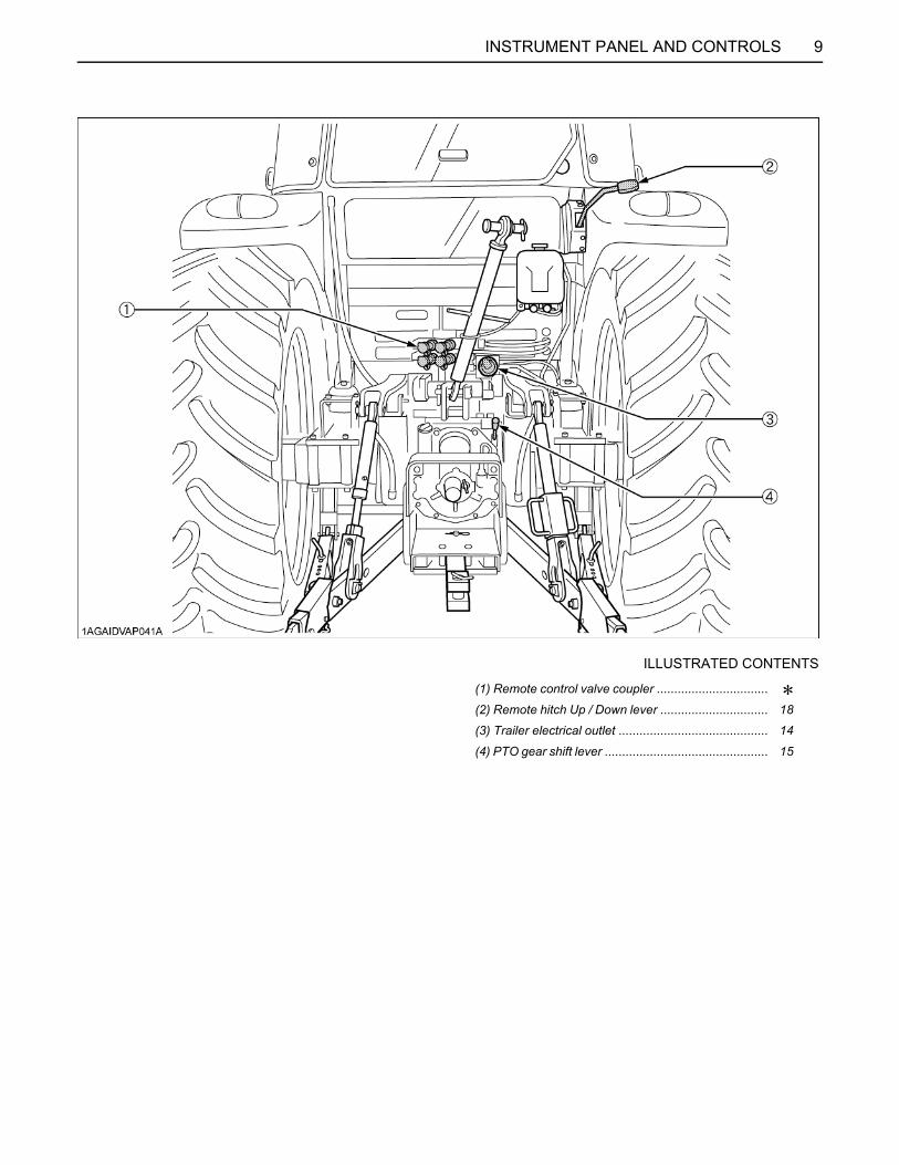
ILLUSTRATED CONTENTS
(1) Remote control valve coupler ................................ D(2) Remote hitch Up / Down lever ............................... 18
(3) Trailer electrical outlet ........................................... 14
(4) PTO gear shift lever ............................................... 15

10 OPERATING THE TRACTOR
OPERATING THE TRACTOR
STARTING[With Dual Speed model]BOperator's Seat
To avoid personal injury:A Make adjustments to the seat only while the
tractor is stopped.A Make sure that the seat is completely secured
after each adjustment.A Do not allow any person other than the
operator to ride on the tractor.
(1) Travel adjust lever(2) Weight / Height adjust lever(3) Backrest tilt adjust lever(4) Arm rest(5) Arm rest angle adjust knob
(A) "UNLOCK"(B) "TO INCREASE ANGLE"(C) "TO DECREASE ANGLE"
C Travel adjustmentUnlock the travel adjust lever and slide the seatbackward or forward, as required. The seat will lock inposition when the lever is released.
C Weight and Height adjustmentTurn on the key switch. The seat should be adjusted forthe operator's weight by briefly pulling up or pushingdown the weight / height adjust lever with the tractor in astationary position and the operator sitting on the seat.The seat can be adjusted in its adjustable range.
A If the seat is lowered below the adjustable range, itautomatically comes up to the lower limit of theadjustable range just when the weight / height adjustlever is released.
A When turning on the key switch, the seat may slightlymove up depending on a preset seat position(height).
A In order to avoid damage of the seat, do not operatethe weight / height adjust lever for more than 1minute.
C Tilt adjustmentPull the backrest tilt adjust lever and tilt the backrest tothe desired position.
C Arm restArmrest may be set at upright position if desired.
C Arm rest angle adjustmentTurn the arm rest angle adjust knob to the desired angle.
A After adjusting the operator's seat, be sure to checkto see that the seat is properly locked,
11OPERATING THE TRACTOR
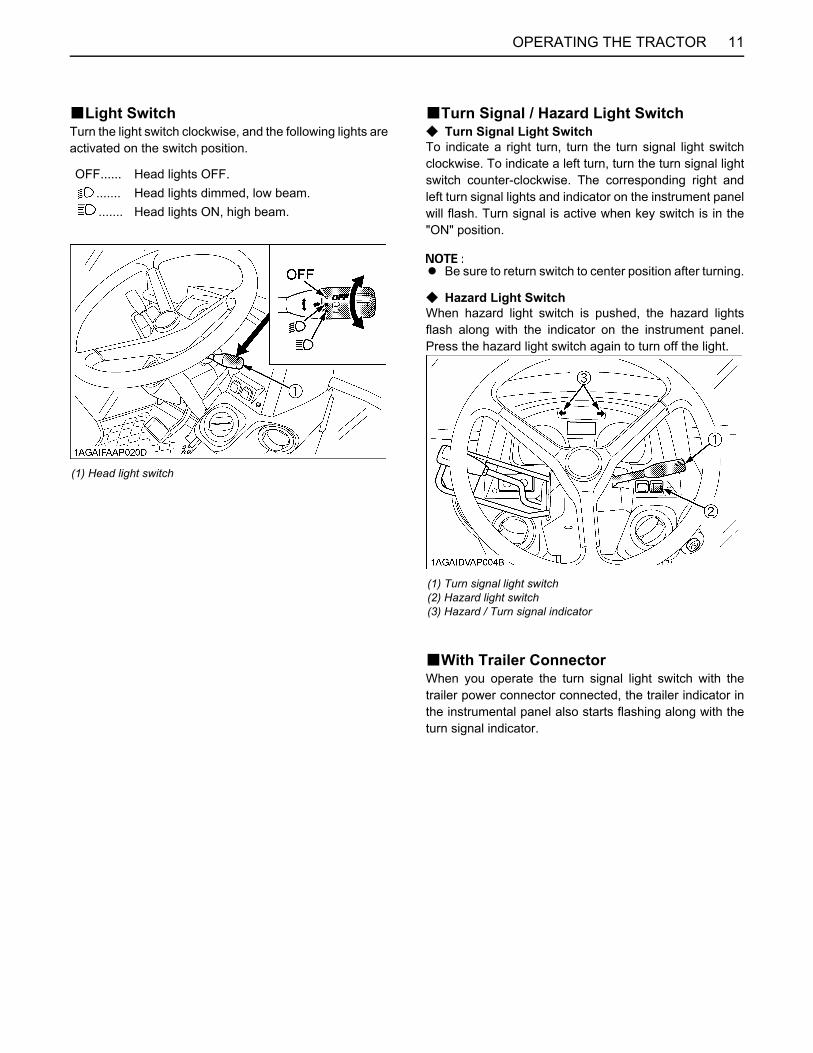
BLight SwitchTurn the light switch clockwise, and the following lights areactivated on the switch position.
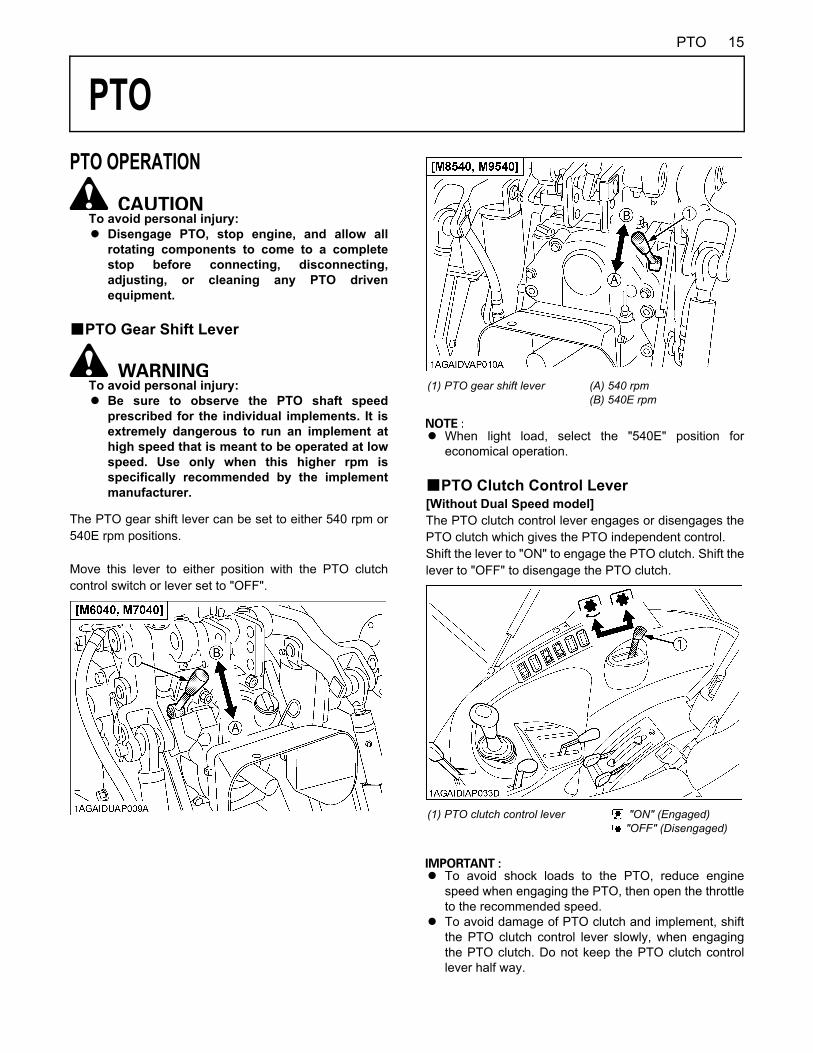
BTurn Signal / Hazard Light SwitchC Turn Signal Light SwitchTo indicate a right turn, turn the turn signal light switchclockwise. To indicate a left turn, turn the turn signal lightswitch counter-clockwise. The corresponding right andleft turn signal lights and indicator on the instrument panelwill flash. Turn signal is active when key switch is in the"ON" position.
A Be sure to return switch to center position after turning.
C Hazard Light SwitchWhen hazard light switch is pushed, the hazard lightsflash along with the indicator on the instrument panel.Press the hazard light switch again to turn off the light.
BWith Trailer ConnectorWhen you operate the turn signal light switch with thetrailer power connector connected, the trailer indicator inthe instrumental panel also starts flashing along with theturn signal indicator.
OFF...... Head lights OFF........ Head lights dimmed, low beam........ Head lights ON, high beam.
(1) Head light switch
(1) Turn signal light switch(2) Hazard light switch(3) Hazard / Turn signal indicator

12 OPERATING THE TRACTOR
PTO RPM / TRAVEL SPEED MONITORBPTO Speed Display Mode SwitchingThe PTO speed display mode has been factory-set as table below. Do not attempt to change the code. Otherwise thecorrect PTO speed will not be displayed in the LCD monitor.(NOTE: The current code can be checked in the following procedure.)
C Switching procedure

13OPERATING THE TRACTOR
PARKING[With Dual Speed model]
To avoid personal injury:BEFORE DISMOUNTING TRACTORA ALWAYS SET PARKING BRAKE AND LOWER
ALL IMPLEMENTS TO THE GROUND.Leaving transmission in gear with the enginestopped will not prevent the tractor fromaccidental rolling.
A STOP THE ENGINE AND REMOVE THE KEY.
BParking Brake LeverPull the parking brake lever up to park.The parking brake indicator light on the EasyChecker(TM) will come on while the parking brake is set.
A If the tractor is operated with the parking brake set, theparking brake will be damaged.
BGear Locked Parking Lever1. To set the gear locked parking lever;
(1) Depress the brake pedals.(2) Place the main gear shift lever in neutral position.(3) Push the gear locked parking lever to parking
position.2. To release the gear locked parking lever, depress the
brake pedals and shift the lever to transport position.
A Bring the tractor to a complete stop before applying thegear locked parking lever.
A The gear locked parking lever can be turned ON andOFF only when the main gear shift lever is at theneutral position.
A In moving the gear locked parking lever, you may feelit heavy some time or light other time. This is not atrouble, however.
When parking the tractor, set the both parking levers.
(1) Parking brake lever(2) Release button
(A) "PULL"
(1) Parking brake indicator light
(1) Gear locked parking lever (A) "PARKING POSITION"(B) "TRANSPORT POSITION"

OPERATING THE TRACTOR14
OPERATING TECHNIQUESBTrailer Electrical OutletA trailer electrical outlet is supplied for use with trailer orimplement.
C Function of each terminals in trailer electricaloutlet
(1) Trailer electrical outlet
Terminal Function
(1) Turn signal light (LH)
(2) ---
(3) Ground
(4) Turn signal light (RH)
(5)Tail lightSidemarker lightParking light
(6) Brake stop light
(7) Registration plate light
15PTO
PTO
PTO OPERATIONTo avoid personal injury:A Disengage PTO, stop engine, and allow all
rotating components to come to a completestop before connecting, disconnecting,adjusting, or cleaning any PTO drivenequipment.
BPTO Gear Shift Lever
To avoid personal injury:A Be sure to observe the PTO shaft speed
prescribed for the individual implements. It isextremely dangerous to run an implement athigh speed that is meant to be operated at lowspeed. Use only when this higher rpm isspecifically recommended by the implementmanufacturer.
The PTO gear shift lever can be set to either 540 rpm or540E rpm positions.
Move this lever to either position with the PTO clutchcontrol switch or lever set to "OFF".
A When light load, select the "540E" position foreconomical operation.
BPTO Clutch Control Lever[Without Dual Speed model]The PTO clutch control lever engages or disengages thePTO clutch which gives the PTO independent control.Shift the lever to "ON" to engage the PTO clutch. Shift thelever to "OFF" to disengage the PTO clutch.
A To avoid shock loads to the PTO, reduce enginespeed when engaging the PTO, then open the throttleto the recommended speed.
A To avoid damage of PTO clutch and implement, shiftthe PTO clutch control lever slowly, when engagingthe PTO clutch. Do not keep the PTO clutch controllever half way.
(1) PTO gear shift lever (A) 540 rpm(B) 540E rpm
(1) PTO clutch control lever "ON" (Engaged) "OFF" (Disengaged)

PTO16
A Tractor engine will not start if PTO clutch control leveris in the engaged "ON" position.
A If the PTO system is engaged and you stand up fromthe seat, the warning buzzer will whistle for about 10seconds after standing up.This is because the tractor is equipped with "OperatorPresence Control System".
C PTO Clutch IndicatorThe PTO clutch indicator turns on while PTO clutchcontrol lever is in "ON" (Engage) position.
BPTO Clutch Control Switch[With Dual Speed model]The PTO clutch control switch engages or disengages thePTO clutch which gives the PTO independent control.Turn the switch to "ON" to engage the PTO clutch. Turnthe switch to "OFF" to disengage the PTO clutch.
C PTO Clutch Control Switch
To turn ONWhile pushing the switch, turn clockwise to the " "position and release your hand. (In the ON position,switch slightly rises itself.)
Tractor model(A) 540 (B) 540E
PTO / Engine speed rpm
M6040M7040 540 / 2160 540 / 1825
M8540M9540 540 / 2035 540 / 1519
(1) PTO clutch indicator
(1) PTO clutch control switch "ON" "OFF"

17PTO
To Turn OFFTap on top of the switch, and the switch will return to theOFF position.
A To avoid shock loads to the PTO, reduce enginespeed when engaging the PTO, then open the throttleto the recommended speed.
A Tractor engine will not start if PTO clutch control switchis in the engaged "ON" position.
A If the PTO system is engaged and you stand up fromthe seat, the warning buzzer will whistle for about 10seconds after standing up.This is because the tractor is equipped with "OperatorPresence Control System".
C PTO Clutch IndicatorThe PTO clutch indicator turns on while PTO clutchcontrol switch is in "ON" (Engage) position.
BLCD Monitor Message1. The PTO rpm can be checked in the LCD monitor.
(See "PTO RPM / TRAVEL SPEED MONITOR" in"OPERATING THE TRACTOR" section.)
2. When the PTO system gets engaged (ON), theindicator lights up.
(A) "PUSH"
(1) PTO clutch indicator
(1) LCD monitor(2) PTO clutch indicator

18 3-POINT HITCH & DRAWBAR
3-POINT HITCH & DRAWBAR
3-POINT HITCHBRemote Hitch UP / DOWN Lever[With Dual Speed model]To avoid personal injury:A Do not use the Remote hitch up / down lever
when the implement is attached on the 3-pointhitch.
This lever is used to raise and lower the 3-point hitch foraligning the arm with the implement only.
DRAWBAR
To avoid personal injury:A Never pull from the top link, the rear axle or any
point above the drawbar. Doing so could causethe tractor to tip over rearward causingpersonal injury or death.
BAdjusting Drawbar LengthWhen towing an implement, it is recommended that the(A) hole in drawbar be utilized.The drawbar load is specified in the "IMPLEMENTLIMITATIONS" section.
(1) Remote hitch up / down lever (A) "UP"(B) "DOWN"
(1) Drawbar(2) Pivot pin
Holes: (A), (B)

193-POINT HITCH & DRAWBAR
BSwing DrawbarThe drawbar can be used in 3 different ways as illustratedbelow. Assemble it correctly with locating pins.
(1) Drawbar(2) Locating pin

20 HYDRAULIC UNIT
HYDRAULIC UNIT
REMOTE HYDRAULIC CONTROL SYSTEMThe hydraulic auxiliary control valves can be installed upto triple segments.It is not possible to use triple segments with flow controlvalve.BRemote Control ValveThere are 3 types of remote valves available for thesemodels.A Double acting valve with detents and self cancelling:
This valve may be placed in the detent mode. Thelever will stay in this position until the pressure reachesa predetermined level or a cylinder reaches the end ofits stroke. Then it will automatically return to neutral.
A Double acting valve with float position:This valve may be placed in the float mode with thecontrol lever all the way forward. The cylinder is free toextend or retract, letting an implement such as aloader bucket follow the ground.
A Single/double acting valve:This valve can be utilized as single or double actingvalve by adjusting the auxiliary control valve selectorknob located on the valve.
1) Turn the auxiliary control valve selector knobclockwise all the way to utilize as single actingvalve.
2) Turn the auxiliary control valve selector knobanticlockwise all the way to utilize as doubleacting valve.
A This float valve can be attached as the second or thirdsegment.
BRemote Control Valve LeverThe remote control valve lever directs pressurized oil flowto the implement hydraulic system.
[Without Dual Speed model]
(1) Single / double acting valve(2) Auxiliary control valve selector knob
(A) Double acting(B) Single acting
(1)(2)
Remote control valve lever with Double acting valve / Detents and self cancellingRemote control valve lever with Single / Double acting valve
PressureReturning
Lever (1)Lever position
Z (detent) Y X Z (detent)
Port[A] Out In
[B] In Out
Double-acting Single-acting
Lever (2) Y X Y X
Port[C] Out In - -
[D] In Out In Out

21HYDRAULIC UNIT
[With Dual Speed model]A Do not hold the lever in the "REARWARD" or
"FORWARD" position once the remote cylinder hasreached the end of the stroke, as this will cause oil toflow through the relief valve. Forcing oil through therelief valve for extended periods will overheat the oil.
A When using the tractor hydraulic system to power frontloader, do not operate boom and bucket cylinderssimultaneously.
A Connect the pressure of load side of implementcylinders to ports [B] or [D] which have built in loadcheck valve to prevent leak down.
A To use the single-acting cylinder with the float valve,connect this cylinder to the [B] or [D] port.To extend a single-acting cylinder, pull the remotecontrol valve lever rearward. To retract a cylinder,push it fully forward to the "FLOAT" position. Do nothold it in the "FORWARD" position, the transmissionfluid may be overheat.
(1)(2)
Remote control valve lever with Double acting valve / Detents and self cancellingRemote control valve lever with Double acting valve / Float position
PressureReturning
Lever (1)Lever position
Z (detent) Y X Z (detent)
Port[A] Out In
[B] In Out
Lever position
Lever (2) Z (detent) Y X
Port[C] In
FloatOut In
[D] Out In Out

22 TIRES, WHEELS AND BALLAST
TIRES, WHEELS AND BALLAST
TIRESTo avoid personal injury:A Do not attempt to mount a tire on a rim. This
should be done by a qualified person with theproper equipment.
A Always maintain the correct tire pressure.Do not inflate tires above the recommendedpressure shown in the operator's manual.
A Do not use tires other than those approved byKUBOTA.
A When optional different-diameter tires are fitted on themachine, the travel speed display mode must bechanged. Otherwise the travel speed will not getcorrectly displayed. Such mode switching is alsoneeded when the original tires are back on themachine.(See "PTO RPM / TRAVEL SPEED MONITOR" in"OPERATING THE TRACTOR" section.)
BInflation PressureThough the tire pressure is factory-set to the prescribedlevel, it naturally drops slowly in the course of time. Thus,check it everyday and inflate as necessary.
A Maintain the maximum pressure in front tires, if usinga front loader or when equipped with a full load of frontweights.
BDual TiresDual tires are not approved.
WHEEL ADJUSTMENT
To avoid personal injury:A When working on slopes or when working with
trailer, set the wheel tread as wide as practicalfor maximum stability.
A Support tractor securely on stands beforeremoving a wheel.
A Do not work under any hydraulically supporteddevices. They can settle, suddenly leak down,or be accidentally lowered. If necessary to workunder tractor or any machine elements forservicing or adjustment, securely support themwith stands or suitable blocking beforehand.
A Never operate tractor with a loose rim, wheel,or axle.
Tire sizes Inflation Pressure
Front
6.50-16, 6PR 320 kPa (3.2 kgf/cm )
7.50-16, 6PR 280 kPa (2.8 kgf/cm )
9.5L-15, 6PR 220 kPa (2.2 kgf/cm )
9.5-20, 6PR 200 kPa (2.0 kgf/cm )
9.5-22, 6PR 200 kPa (2.0 kgf/cm )
9.5-24, 6PR 180 kPa (1.8 kgf/cm )
360/70R24 160 kPa (1.6 kgf/cm )
Rear
14.9-28, 6PR 140 kPa (1.4 kgf/cm )
16.9-28, 6PR 120 kPa (1.2 kgf/cm )
16.9-30, 6PR 120 kPa (1.2 kgf/cm )
18.4-30, 6PR 120 kPa (1.2 kgf/cm )
16.9-34, 6PR 120 kPa (1.2 kgf/cm )
480/70R34 120 kPa (1.2 kgf/cm )
23TIRES, WHEELS AND BALLAST
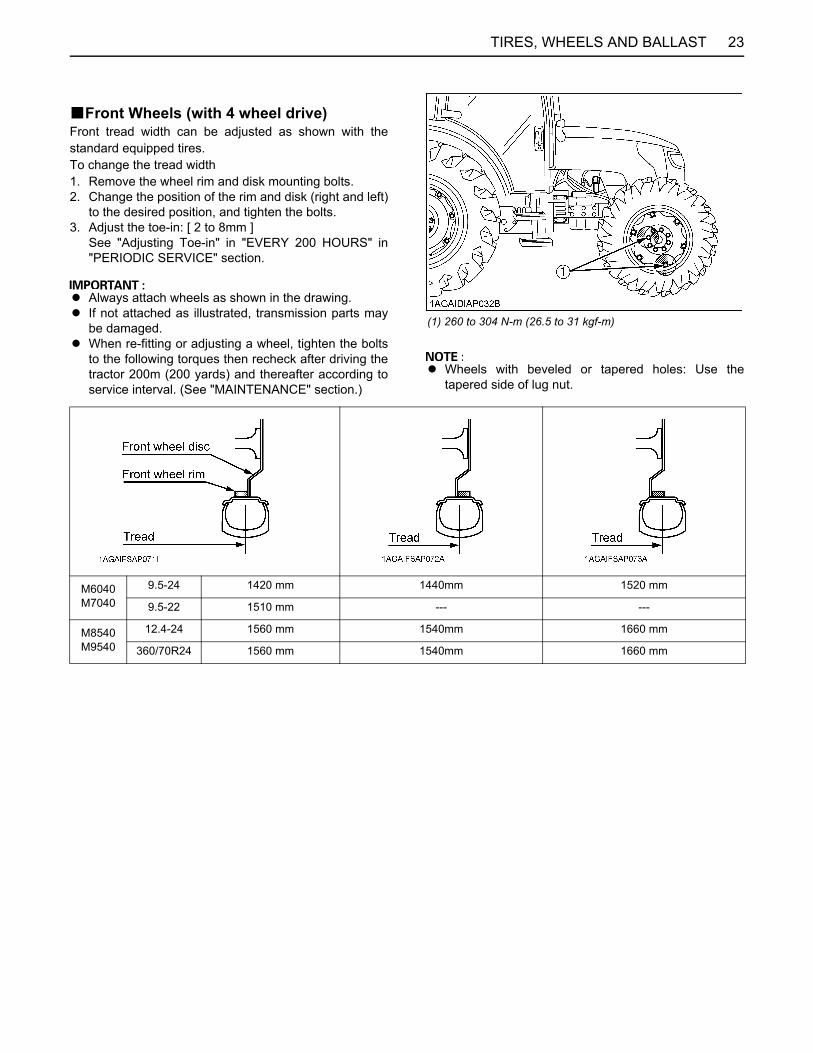
BFront Wheels (with 4 wheel drive)Front tread width can be adjusted as shown with thestandard equipped tires.To change the tread width1. Remove the wheel rim and disk mounting bolts.2. Change the position of the rim and disk (right and left)
to the desired position, and tighten the bolts.3. Adjust the toe-in: [ 2 to 8mm ]
See "Adjusting Toe-in" in "EVERY 200 HOURS" in"PERIODIC SERVICE" section.
A Always attach wheels as shown in the drawing.A If not attached as illustrated, transmission parts may
be damaged.A When re-fitting or adjusting a wheel, tighten the bolts
to the following torques then recheck after driving thetractor 200m (200 yards) and thereafter according toservice interval. (See "MAINTENANCE" section.)
A Wheels with beveled or tapered holes: Use thetapered side of lug nut.
(1) 260 to 304 N-m (26.5 to 31 kgf-m)
M6040M7040
9.5-24 1420 mm 1440mm 1520 mm
9.5-22 1510 mm --- ---
M8540M9540
12.4-24 1560 mm 1540mm 1660 mm
360/70R24 1560 mm 1540mm 1660 mm
TIRES, WHEELS AND BALLAST24
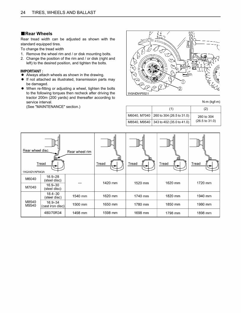
BRear WheelsRear tread width can be adjusted as shown with thestandard equipped tires.To change the tread width1. Remove the wheel rim and / or disk mounting bolts.2. Change the position of the rim and / or disk (right and
left) to the desired position, and tighten the bolts.
A Always attach wheels as shown in the drawing.A If not attached as illustrated, transmission parts may
be damaged.A When re-fitting or adjusting a wheel, tighten the bolts
to the following torques then recheck after driving thetractor 200m (200 yards) and thereafter according toservice interval.(See "MAINTENANCE" section.)
N-m (kgf-m)
(1) (2)
M6040, M7040 260 to 304 (26.5 to 31.0) 260 to 304(26.5 to 31.0)M8540, M9540 343 to 402 (35.0 to 41.0)
25MAINTENANCE
MAINTENANCE
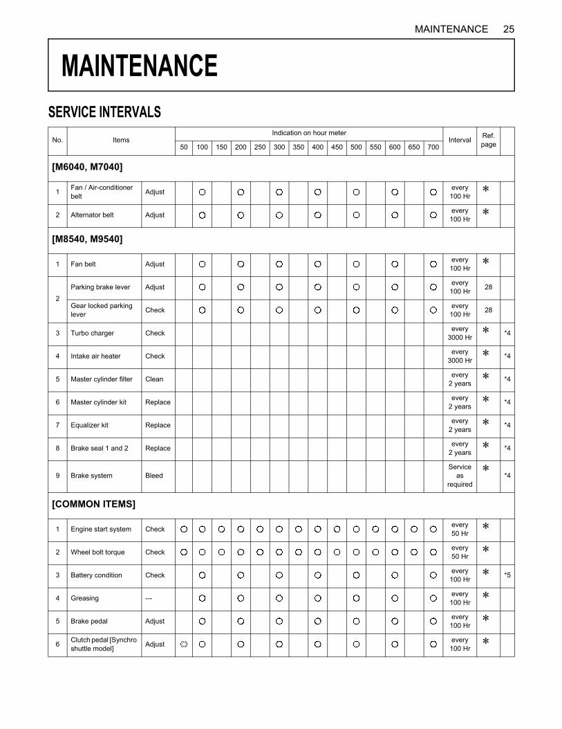
SERVICE INTERVALSNo. ItemsIndication on hour meter
Interval Ref.page50 100 150 200 250 300 350 400 450 500 550 600 650 700
[M6040, M7040]
1 Fan / Air-conditioner belt Adjust every
100 HrD
2 Alternator belt Adjust every100 Hr
D
[M8540, M9540]
1 Fan belt Adjust every100 Hr
D
2
Parking brake lever Adjust every100 Hr 28
Gear locked parking lever Check every
100 Hr 28
3 Turbo charger Check every3000 Hr
D *4
4 Intake air heater Check every3000 Hr
D *4
5 Master cylinder filter Clean every2 years
D *4
6 Master cylinder kit Replace every2 years
D *4
7 Equalizer kit Replace every2 years
D *4
8 Brake seal 1 and 2 Replace every2 years
D *4
9 Brake system BleedService
asrequired
D*4
[COMMON ITEMS]
1 Engine start system Check every50 Hr
D
2 Wheel bolt torque Check every50 Hr
D
3 Battery condition Check every100 Hr
D *5
4 Greasing --- every100 Hr
D
5 Brake pedal Adjust every100 Hr
D
6 Clutch pedal [Synchro shuttle model] Adjust every
100 HrD
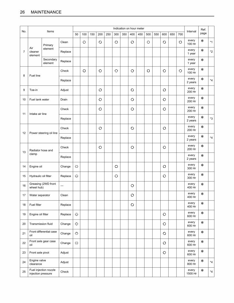
26 MAINTENANCE
7Air cleaner element
Primary element
Clean every100 Hr
D *1
Replace every1 year
D *2
Secondary element Replace every
1 yearD
8 Fuel line
Check every100 Hr
D
Replace every2 years
D *4
9 Toe-in Adjust every200 Hr
D
10 Fuel tank water Drain every200 Hr
D
11 Intake air line
Check every200 Hr
D
Replace every2 years
D *3
12 Power steering oil line
Check every200 Hr
D
Replace every2 years
D *4
13 Radiator hose and clamp
Check every200 Hr
D
Replace every2 years
D
14 Engine oil Change every300 Hr
D
15 Hydraulic oil filter Replace every300 Hr
D
16 Greasing (2WD front wheel hub) --- every
400 HrD
17 Water separator Clean every400 Hr
D
18 Fuel filter Replace every400 Hr
D
19 Engine oil filter Replace every600 Hr
D
20 Transmission fluid Change every600 Hr
D
21 Front differential case oil Change every
600 HrD
22 Front axle gear case oil Change every
600 HrD
23 Front axle pivot Adjust every600 Hr
D
24 Engine valve clearance Adjust every
800 HrD *4
25 Fuel injection nozzle injection pressure Check every
1500 HrD *4
No. ItemsIndication on hour meter
Interval Ref.page50 100 150 200 250 300 350 400 450 500 550 600 650 700

27MAINTENANCE
A The jobs indicated by must be done after the first 50 hours of operation.*1 Air cleaner should be cleaned more often in dusty conditions than in normal conditions.*2 Every year or every 6 times of cleaning.*3 Replace only if necessary.*4 Consult your local KUBOTA Dealer for this service.*5 When the battery is used for less than 100 hours per year, check the battery condition by reading the indicator annually.
26 Injection pump Check every3000 Hr
D *4
27 Cooling system Flush every2 years
D
28 Coolant Change every2 years
D
29 Lift cylinder hose Replace every2 years
D *4
30 Fuel system BleedService
asrequired
D
31 Clutch housing water DrainService
asrequired
D
32 Fuse ReplaceService
asrequired
28
33 Light bulb ReplaceService
asrequired
30
D : See operator's manual issued separately for the sister model. [M6040, M7040, M8540, M9540]
No. ItemsIndication on hour meter
Interval Ref.page50 100 150 200 250 300 350 400 450 500 550 600 650 700
28 PERIODIC SERVICE
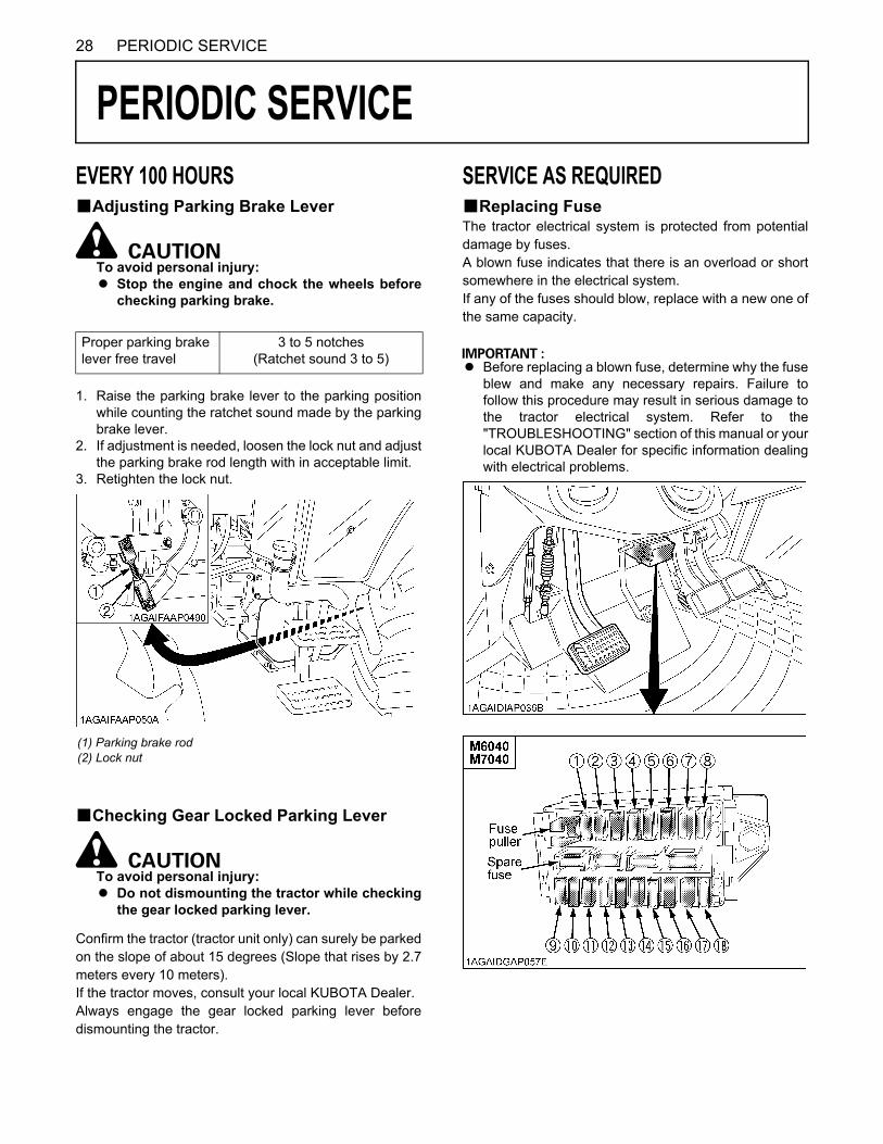
PERIODIC SERVICE
EVERY 100 HOURSBAdjusting Parking Brake LeverTo avoid personal injury:A Stop the engine and chock the wheels before
checking parking brake.
1. Raise the parking brake lever to the parking positionwhile counting the ratchet sound made by the parkingbrake lever.
2. If adjustment is needed, loosen the lock nut and adjustthe parking brake rod length with in acceptable limit.
3. Retighten the lock nut.
BChecking Gear Locked Parking Lever
To avoid personal injury:A Do not dismounting the tractor while checking
the gear locked parking lever.
Confirm the tractor (tractor unit only) can surely be parkedon the slope of about 15 degrees (Slope that rises by 2.7meters every 10 meters).If the tractor moves, consult your local KUBOTA Dealer.Always engage the gear locked parking lever beforedismounting the tractor.
SERVICE AS REQUIREDBReplacing FuseThe tractor electrical system is protected from potentialdamage by fuses.A blown fuse indicates that there is an overload or shortsomewhere in the electrical system.If any of the fuses should blow, replace with a new one ofthe same capacity.
A Before replacing a blown fuse, determine why the fuseblew and make any necessary repairs. Failure tofollow this procedure may result in serious damage tothe tractor electrical system. Refer to the"TROUBLESHOOTING" section of this manual or yourlocal KUBOTA Dealer for specific information dealingwith electrical problems.
Proper parking brake lever free travel
3 to 5 notches (Ratchet sound 3 to 5)
(1) Parking brake rod(2) Lock nut

29PERIODIC SERVICE
FuseNo.
Capacity(A) Protected circuit
(1) 5 Starter Relay
(2) 15 Auxiliary Power / Air Suspension Seat (if equipped)
(3) 15 Work Light (Front, Side)(4) 10 Air Conditioner (Compressor)(5) 30 Air Conditioner (Fan Motor)(6) 15 Cigarette Lighter(7) 15 Work Light (Front)(8) 15 Work Light (Rear)(9) 20 Spare Fuse
(10) 20 Flasher (Hazard)(11) 20 Head Light, Tail Lamp(12) 10 Meter, Radio (Back Up), Horn(13) 10 Turn Signal, Stop Lamp(14) 5 Meter Panel, OPC(15) 5 Alternator, Engine, Heater(16) 15 Wiper(17) 5 Air Conditioner (Control)(18) 5 Radio(19) 100 Charge(20) 50 Air Heater(21) 50 Head Light, Hazard(22) 30 Work Light, Fuel Cut Solenoid(23) 30 Key Switch(24) 30 Electrical Outlet(25) 40 Air Conditioner(26) 15 Air Suspension Seat (if equipped)

PERIODIC SERVICE30
BReplacing Light Bulb
Light CapacityHead lights 12 V, 55 / 60 W (H4)Turn signal / Hazard lights 12 V, 21 WBrake stop light / Tail light 12 V, 21 / 5 WWork light (for outer roof) 12 V, 55 WFront work light 12 V, 21 WDome light (Room lamp) 12 V, 5 W
31OPTIONS
OPTIONS
Consult your local KUBOTA Dealer for further details.A Double Acting Remote Hydraulic Control Valve withDetents and Self-Cancelling
A Flow Control Valve KitA Double Acting Remote Hydraulic Control Valve with
Detents and Self-Cancelling for Flow Control ValveA Double Acting Remote Hydraulic Control Valve with
Float PositionA Front end weights
For front ballastA Rear Wheel Weights
For rear ballast