operator's manual holman conveyor...
TRANSCRIPT
OPERATOR'S MANUAL HOLMAN CONVEYOR TOASTERS
MODELS T710(H, TW, TX) T714(H, TW, TX) S710(H) S714(H) B710H FOR SERVICE INFORMATION
U.S. AND CANADA CALL: 1-800-264-7827 24 HOURS/DAY 7 DAYS/WEEK
TABLE OF CONTENTS UNCRATING AND INSPECTION PAGE 1 ASSEMBLY AND INSTALLATION PAGE 1 POWER SAVER SWITCH PAGE 2 SECURITY FEATURES PAGE 2A COOKING PROCEDURES PAGE 3, 4 CLEANING PROCEDURES PAGE 4 TROUBLESHOOTING GUIDE PAGE 5, 6 MAINTENANCE PROCEDURES PAGE 7, 8, 9 PARTS LIST/EXPLODED VIEW PAGE 10, 11, 12, 13
DRAWINGS
CRUMB TRAY PAGE 1 LOAD AND UNLOAD TRAYS PAGE 1 ADJ. HEAT SHIELD, FRONT VIEW PAGE 3 COMPONENT ARRANGEMENT PAGE 6 HEATER TUBE INSTALLATION PAGE 7 DRIVE SYSTEM PAGE 9 WIRING DIAGRAMS [T710(H,TW)] PAGE 15, 16 WIRING DIAGRAMS [T714(H,TW)] PAGE 16, 17 WIRING DIAGRAMS [B710(H)] PAGE 18 WIRING DIAGRAMS [S710(H), Jamba Juice] PAGE 19 WIRING DIAGRAMS [S714(H)] PAGE 20
REV. 1/31/2011 2M-HG0102

Page 1 OPERATOR'S MANUAL
HOLMAN CONVEYOR TOASTERS MODELS T710(H, TW, TX) T714(H, TW, TX) S710(H) S714(H) B710H
UNCRATING AND INSPECTION Unpack unit and components from container. Remove all visible packing
material, inspect unit for damage. If damage is discovered, file a claim immediately with the carrier that handled the shipment.
ASSEMBLY AND INSTALLATION A. Attach legs by screwing into weld nuts, as shown below.
AT EACH CORNER ON BOTTOM SIDE OF TOASTER
LEVELING OF THE TOASTER CAN BE DONE BY TURNING
THE FOOT SECTION OF THE LEG COUNTER CLOCKWISE
ADJUSTABLE LEG: SCREWS INTO WELD NUT LOCATED
B. Anti Skid pads are available at no charge and may be adhered to the foot
section of each leg to prevent sliding. Call 1-800-225-3958 for details. WARNING: the National Sanitation Foundation does not approve Use of these pads.
C. Place load and unload trays as shown below.
LOAD UP TRAY
HEAT REFLECTOR / CRUMB TRAY
TOAST CHUTETOAST CHUTE(REAR DISCHARGE)
CAUTION: DO NOT OPERATE UNIT WITHOUT
CRUMB TRAY PROPERLY POSITIONED
AS THIS WILL CAUSE OVERHEATING IN THE
CONTROL BOX.
WARNING: MAKE SURE ALL INPUT POWER IS OFF BEFORE INSTALLING/REMOVING
ANY PARTS. WARNING: BEFORE INSTALLING UNIT(S), CHECK WITH LOCAL POWER COMPANY TO
DETERMINE ACTUAL VOLTAGE AT JOB SITE. NEVER PLUG A 208-VOLT UNIT INTO 240 VOLTS OR A 240 VOLT UNIT INTO 208 VOLTS.
WARNING: BE ABSOLUTELY SURE THE GROUND CONNECTION FOR THE RECEPTACLE IS PROPERLY WIRED. NEVER CONNECT UNIT TO POWER WITHOUT PROPER GROUND CONNECTIONS. IMPROPER GROUND MAY RESULT IN SEVERE INJURY OR FATALITY.
REVISED 9/10/2008
Page 2
OPERATOR'S MANUAL HOLMAN CONVEYOR TOASTERS
MODELS T710(H, TW, TX) T714(H, TW, TX) S710(H) S714(H) B710H OPERATION
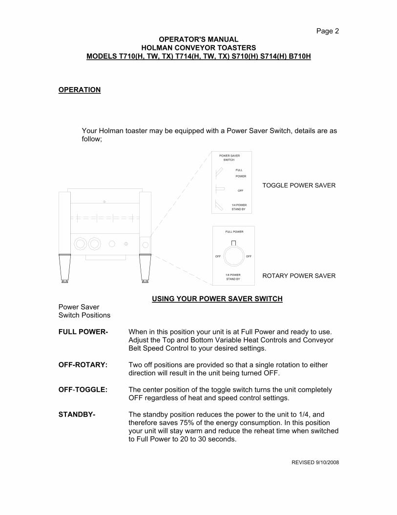
Your Holman toaster may be equipped with a Power Saver Switch, details are as follow;
ROTARY POWER SAVER
TOGGLE POWER SAVER
1/4 POWERSTAND BY
OFF
FULL
POWER
POWER SAVERSWITCH
FULL POWER
OFFOFF
1/4 POWER STAND BY
USING YOUR POWER SAVER SWITCH Power Saver Switch Positions FULL POWER- When in this position your unit is at Full Power and ready to use.
Adjust the Top and Bottom Variable Heat Controls and Conveyor Belt Speed Control to your desired settings.
OFF-ROTARY: Two off positions are provided so that a single rotation to either
direction will result in the unit being turned OFF. OFF-TOGGLE: The center position of the toggle switch turns the unit completely
OFF regardless of heat and speed control settings. STANDBY- The standby position reduces the power to the unit to 1/4, and
therefore saves 75% of the energy consumption. In this position your unit will stay warm and reduce the reheat time when switched to Full Power to 20 to 30 seconds.
REVISED 9/10/2008

Page 2A
OPERATOR'S MANUAL HOLMAN CONVEYOR TOASTERS
MODELS S710(H), S714(H)
FULL KEY LOCKING COVERFITS OVER CONTROLS ANDSIDE PANELS TO PREVENTTAMPERING
S710LOK.WMK
HOLMAN
Fig. 1
SECURITY COVER : Your Holman models S710 and S714 are quipped with a full front key locking cover (fig.1). This over fits over the front and sides of the unit. The security cover must be removed with a key in order to gain access to the controls, side panels, legs and toast chute to be removed. To remove, unlock the cover using the key. Pull locked side of cover out and away from the unit. The right side will release at the same time. To replace the cover, Hook the right side of the cover over the latch on right front of the unit while sliding the left side of the cover over the lock. Secure cover using key.
S710CHUT.WMF
SECURITY TOASTCHUTE MOUNTINGROD
TOAST CHUTE MOUNTING RODSLIDES THOUGH MOUNTING HOLE IN CHASSIS AND THROUGH LOOP INTOP OF TOAST CHUTE
Fig. 2
TOAST CHUTE ; To install the toast chute (fig. 2), Remove the left side panel by removing two screws and pulling the top part of the panel out while lifting up. Remove the mounting rod by sliding it through chassis. Next, place the toast chute beneath toaster as shown. Line up the looped end of toast chute with holes in the rear of toaster as shown. Insert mounting rod through the holes in chassis and the toast chute (If legs have not been installed, do so now). Reinstall side panel and secure with screws. Toast chute is now ready for use.
S710LEG.WMF
HOLMAN
SECURITY COUNTER MOUNTINGBRACKET ATTACHES TO LEG FOOTAND IS SECURED TO COUNTER WITH A SCREW.
MOUNTINGBRACKET
FOOT SCREWSINTO BOTTOMOF LEG
LEG SCREWSINTO THE BOTTOMOF TOASTER
COTTER PIN
KEY LOCK
COTTER PIN
Fig. 3
LEGS : To secure the toaster to the counter (fig.3), Remove both side panels by removing two screws and pulling the top of the panel out while lifting up. Unscrew the foot of each leg and slide counter-mounting brackets onto the legs. Screw the foot back onto each leg and install legs onto the toaster. Place the small cotter pin through the holes in threaded portion of each leg. Secure the mounting brackets to the counter with a screw or bolt. Reinstall both side panels and secure with screws. NOTE: Security models are not supplied with a power saver switch.
REVISED 9/10/2008
PAGE 3 OPERATOR'S MANUAL

HOLMAN CONVEYOR TOASTERS MODELS T710(H, TW, TX) T714(H, TW, TX) S710(H) S714(H) B710H
COOKING PROCEDURES A. BREAD TOASTING NOTE: Models TX710(H) and TX714(H) have an extended conveyor belt in lue of a load up tray. Place (do not press) the product on the extended conveyor belt for toasting or heating. Follow the instructions listed below for cooking and operation procedures. 1. On models T710H, TX710(H), T714H, TX714(H) and B710H, S710(H), S714(H) lower the front heat shield all the way down, leave just enough clearance for bread slices to pass under the shield into the cooking cavity (See illustration below).
ADJUSTABLE HEAT SHUTTER
2. Turn top and bottom heat controls to HI; turn conveyor speed control to 50. 3. Allow warm up time of 5 to 10 minutes. 4. Test with a slice of bread. a. If toast is too light, turn conveyor speed control counterclockwise to a slower speed. b. If toast is too dark, turn conveyor speed control clockwise to a faster speed. B. MODELS T710(H), TX710H, T714(H), TX714H, S710(H), S714(H)-BUN TOASTING 1. Buns may be top or bottom toasted. Turn appropriate heat control to HI, set conveyor speed control to 50. 2. On models with high (3") clearance (T710H, TX710H, T714H, TX714H, S710H, S714H), lower the front heat shield as far as possible, leave just enough clearance for the bun half to pass under and into the cooking cavity. 3. Test with a half of a bun. a. If bun half is too light, turn conveyor speed control counterclockwise to a slower speed. b. If bun half is too dark, turn conveyor speed control clockwise to a faster speed. Cooking procedures continued on page 4 REVISED 9/10/2008
PAGE 4
OPERATOR'S MANUAL

HOLMAN CONVEYOR TOASTERS MODELS T710(H, TW, TX) T714(H, TW, TX) S710(H) S714(H) B710H
COOKING PROCEDURES CONT. C. MODEL B710(H) The model B710(H) has higher wattage tubes on the top than on the bottom, therefore when placing the bun halves on the conveyor you should place them cut side up. D. DEEP TOASTING OR BAKING (Units with Variable Heat Controls). Food products that require deep heating without exterior toasting may be heated by reducing the oven temperature (lowering the top and/or bottom heat controls) and cooking at slower speeds. Some foods may require more top heat than bottom heat or vice versa. Every product will require some experimentation to arrive at the correct balance of heat control and conveyor speed settings. Each time a setting is changed allow about 5 minutes for the unit to stabilize. CLEANING PROCEDURES 1. Turn top and bottom heat controls to the OFF position. 2. For lightly soiled conveyor belts, turn conveyor speed control to fastest setting (100) and wipe with a damp cloth. 3. For heavily soiled conveyors, turn conveyor speed control to fastest setting (100) and wipe with a light abrasive pad. 4. Turn conveyor speed control off. 5. After the unit cools, remove interior crumb tray (as shown below) and clean. Slide crumb tray back into position. DO NOT OPERATE UNIT WITHOUT CRUMB TRAY IN PLACE AS THIS CAUSES OVERHEATING IN THE CONTROL BOX AND MAY ACTIVATE THE HEAT LIMIT SWITCH. 6. Wipe exterior surface of unit. LUBRICATION OF DRIVE CHAIN WITH A GRAPHITE BASED LUBRICANT IS REQUIRED AS PERIODIC MAINTENANCE. CALL HOLMAN FACTORY SERVICE DEPARTMENT FOR DETAILS.
LOAD UP TRAY
HEAT REFLECTOR / CRUMB TRAY
TOAST CHUTE
CAUTION: DO NOT OPERATE UN
WITHOUT CRUMB TRAY AS
THIS CAUSES OVERHEATING IN
THE CONTROL BOX.
CONVEYOR BELT
IDLER SHAFT
DRIVE SHAFT
CONVEYOR LINK, MODEL T710
(TOP VIEW)
SHOWN WITHOUT TOP COVER
CONVEYOR LINK, MODEL T714
REVISED 9/10/2008
PAGE 5 OPERATOR'S MANUAL
HOLMAN CONVEYOR TOASTERS MODELS T710(H, TW, TX) T714(H, TW, TX) S710(H) S714(H) B710H
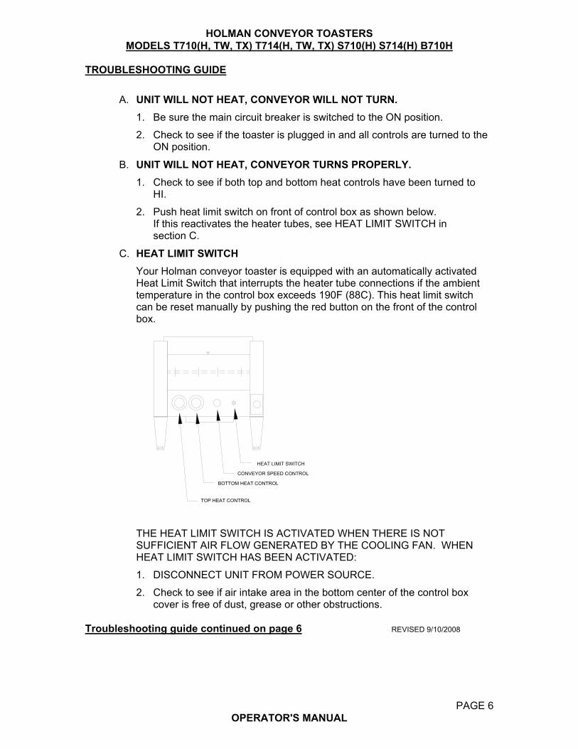
TROUBLESHOOTING GUIDE A. UNIT WILL NOT HEAT, CONVEYOR WILL NOT TURN. 1. Be sure the main circuit breaker is switched to the ON position. 2. Check to see if the toaster is plugged in and all controls are turned to the ON position. B. UNIT WILL NOT HEAT, CONVEYOR TURNS PROPERLY. 1. Check to see if both top and bottom heat controls have been turned to HI. 2. Push heat limit switch on front of control box as shown below. If this reactivates the heater tubes, see HEAT LIMIT SWITCH in section C. C. HEAT LIMIT SWITCH Your Holman conveyor toaster is equipped with an automatically activated Heat Limit Switch that interrupts the heater tube connections if the ambient temperature in the control box exceeds 190F (88C). This heat limit switch can be reset manually by pushing the red button on the front of the control box.
CONVEYOR SPEED CONTROL
BOTTOM HEAT CONTROL
TOP HEAT CONTROL
HEAT LIMIT SWITCH
THE HEAT LIMIT SWITCH IS ACTIVATED WHEN THERE IS NOT SUFFICIENT AIR FLOW GENERATED BY THE COOLING FAN. WHEN HEAT LIMIT SWITCH HAS BEEN ACTIVATED: 1. DISCONNECT UNIT FROM POWER SOURCE. 2. Check to see if air intake area in the bottom center of the control box cover is free of dust, grease or other obstructions. Troubleshooting guide continued on page 6 REVISED 9/10/2008
PAGE 6
OPERATOR'S MANUAL
HOLMAN CONVEYOR TOASTERS MODELS T710(H, TW, TX) T714(H, TW, TX) S710(H) S714(H) B710H
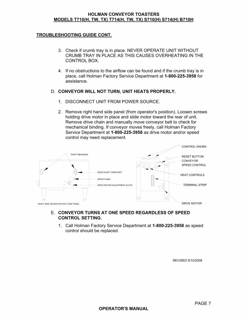
TROUBLESHOOTING GUIDE CONT. 3. Check if crumb tray is in place. NEVER OPERATE UNIT WITHOUT CRUMB TRAY IN PLACE AS THIS CAUSES OVERHEATING IN THE CONTROL BOX. 4. If no obstructions to the airflow can be found and if the crumb tray is in place, call Holman Factory Service Department at 1-800-225-3958 for assistance. D. CONVEYOR WILL NOT TURN, UNIT HEATS PROPERLY. 1. DISCONNECT UNIT FROM POWER SOURCE. 2. Remove right hand side panel (from operator's position). Loosen screws holding drive motor in place and slide motor toward the rear of unit. Remove drive chain and manually move conveyor belt to check for mechanical binding. If conveyor moves freely, call Holman Factory Service Department at 1-800-225-3958 as drive motor and/or speed control may need replacement.
SHAFT BEARINGS
DRIVE SHAFT SPROCKET
DRIVE CHAIN
DRIVE MOTOR ADJUSTMENT SLOTS
RIGHT SIDE SHOWN WITHOUT SIDE PANEL
CONTROL KNOBS
HEAT CONTROLS
DRIVE MOTOR
RESET BUTTONCONVEYORSPEED CONTROL
TERMINAL STRIP
E. CONVEYOR TURNS AT ONE SPEED REGARDLESS OF SPEED CONTROL SETTING. 1. Call Holman Factory Service Department at 1-800-225-3958 as speed control should be replaced. REVISED 9/10/2008
PAGE 7
OPERATOR'S MANUAL

HOLMAN CONVEYOR TOASTERS MODELS T710(H, TW, TX) T714(H, TW, TX) S710(H) S714(H) B710H
MAINTENANCE PROCEDURES A. REPLACING HEATER TUBES (as below) 1. DISCONNECT UNIT FROM POWER SOURCE. 2. Remove right and left side panels. 3. Remove heater tube wire from terminal block connection, keeping top and bottom wires separate. 4. Remove heater tube retainers by removing retaining screws with washer. 5. Gently, pull defective heater tube out of unit. 6. Gently, put new heater tube into unit. 7. Replace heater tube retainers, reconnect heater tube wires to terminal block and install side panels.
HEATER TUBE
HEATER TUBE RETAINER
SIDE PANEL
HEATER TUBE TERMINAL BLOCK (4 POS.)
(2 POS. ON OPOSITE SIDE)
AIR INTAKE
HEATER TUBE RETAINER
Maintenance procedures continued on page 8 REVISED 9/10/2008
PAGE 8 OPERATOR'S MANUAL

HOLMAN CONVEYOR TOASTERS MODELS T710(H, TW, TX) T714(H, TW, TX) S710(H) S714(H) B710H
MAINTENANCE PROCEDURES (CONT.) B. REPLACING FAN MOTOR 1. DISCONNECT UNIT FROM POWER SOURCE. 2. Remove control box cover with fan motor. 3. Unplug power supply cord from fan motor. 4. Remove(4)screws that hold fan motor and grill to cover. 5. Put replacement motor and grill in place and secure to the control box cover with screws. 6. Reconnect power supply cord to fan motor. 7. Replace control box cover.
FAN MOTORSECURED BY 4 SCREWS
AIR INTAKE
CONTROL BOX COVER
AIR INTAKE SCOOP
Maintenance procedures continued on page 9 REVISED 9/10/2008

PAGE 9 OPERATOR'S MANUAL
HOLMAN CONVEYOR TOASTERS MODELS T710(H, TW, TX) T714(H, TW, TX) S710(H) S714(H) B710H
MAINTENANCE PROCEDURES (CONT.) C. REPLACING BELT DRIVE MOTOR 1. DISCONNECT UNIT FROM POWER SOURCE. 2. Remove right side panel and control box covers. 3. Remove sprocket from motor shaft. 4. Remove the wire from terminal block connecting the drive motor to internal
wiring. On units rated 208 or 240 volts, note which color leads are being used for these connections and which lead is capped with white tape. The new motor should use the same arrangement.
5. Remove screws holding motor in place. 6. Put new motor in place and attach loosely with mounting screws. 7. Replace sprocket on motor shaft. 8. Slide motor until the drive chain has about 1/8" slack when lightly pushed at the center of its top open run. 9. Tighten screws to secure motor. 10. Rewire leads same as removed in step 4. 11. Replace side panel and control box cover.
IF ASSISTANCE IS REQUIRED FOR THIS OR ANY OTHER PROCEDURE IN THIS MANUAL CALL HOLMAN FACTORY SERVICE DEPARTMENT AT 1-800-807-9054, 24 HOURS/DAY 7 DAYS/WEEK.
SHAFT BEARINGS
DRIVE SHAFT SPROCKET
DRIVE CHAIN
DRIVE MOTOR ADJUSTMENT SLOTS
RIGHT SIDE SHOWN WITHOUT SIDE PANEL (BOTTOM VIEW)
DRIVE SPROCKET WITH SET SCREW
DRIVE MOTOR
DRIVE MOTORMOUNTING SCREW
REVISED 9/10/2008
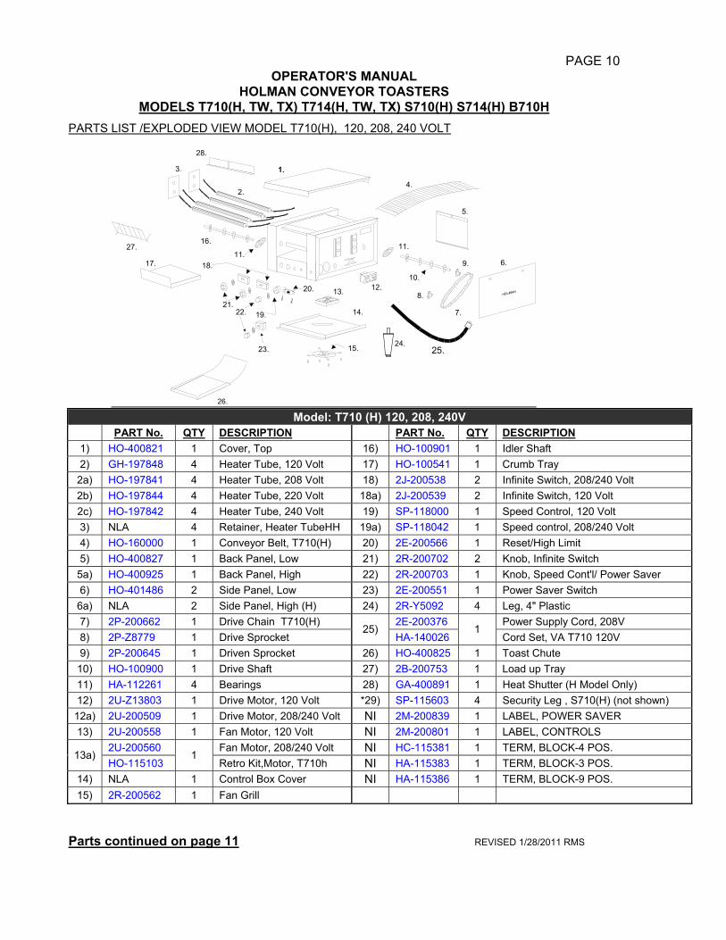
PAGE 10 OPERATOR'S MANUAL
HOLMAN CONVEYOR TOASTERS MODELS T710(H, TW, TX) T714(H, TW, TX) S710(H) S714(H) B710H
PARTS LIST /EXPLODED VIEW MODEL T710(H), 120, 208, 240 VOLT
1.
2.
3..
4.
5.
6.
7.
8.
9.
10.
11.
12.13.
23. 15.
16.
11.18.
19.
20.
21.22.
17.
24.25.
27.
14.
26.
1.
28.
Model: T710 (H) 120, 208, 240V
PART No. QTY DESCRIPTION PART No. QTY DESCRIPTION 1) HO-400821 1 Cover, Top 16) HO-100901 1 Idler Shaft 2) GH-197848 4 Heater Tube, 120 Volt 17) HO-100541 1 Crumb Tray
2a) HO-197841 4 Heater Tube, 208 Volt 18) 2J-200538 2 Infinite Switch, 208/240 Volt 2b) HO-197844 4 Heater Tube, 220 Volt 18a) 2J-200539 2 Infinite Switch, 120 Volt 2c) HO-197842 4 Heater Tube, 240 Volt 19) SP-118000 1 Speed Control, 120 Volt 3) NLA 4 Retainer, Heater TubeHH 19a) SP-118042 1 Speed control, 208/240 Volt 4) HO-160000 1 Conveyor Belt, T710(H) 20) 2E-200566 1 Reset/High Limit 5) HO-400827 1 Back Panel, Low 21) 2R-200702 2 Knob, Infinite Switch
5a) HO-400925 1 Back Panel, High 22) 2R-200703 1 Knob, Speed Cont'l/ Power Saver 6) HO-401486 2 Side Panel, Low 23) 2E-200551 1 Power Saver Switch
6a) NLA 2 Side Panel, High (H) 24) 2R-Y5092 4 Leg, 4" Plastic 7) 2P-200662 1 Drive Chain T710(H) 2E-200376 Power Supply Cord, 208V 8) 2P-Z8779 1 Drive Sprocket
25) HA-140026
1 Cord Set, VA T710 120V
9) 2P-200645 1 Driven Sprocket 26) HO-400825 1 Toast Chute 10) HO-100900 1 Drive Shaft 27) 2B-200753 1 Load up Tray 11) HA-112261 4 Bearings 28) GA-400891 1 Heat Shutter (H Model Only) 12) 2U-Z13803 1 Drive Motor, 120 Volt *29) SP-115603 4 Security Leg , S710(H) (not shown) 12a) 2U-200509 1 Drive Motor, 208/240 Volt NI 2M-200839 1 LABEL, POWER SAVER 13) 2U-200558 1 Fan Motor, 120 Volt NI 2M-200801 1 LABEL, CONTROLS
2U-200560 Fan Motor, 208/240 Volt NI HC-115381 1 TERM, BLOCK-4 POS. 13a)
HO-115103 1
Retro Kit,Motor, T710h NI HA-115383 1 TERM, BLOCK-3 POS. 14) NLA 1 Control Box Cover NI HA-115386 1 TERM, BLOCK-9 POS. 15) 2R-200562 1 Fan Grill
Parts continued on page 11 REVISED 1/28/2011 RMS

PAGE 11
OPERATOR'S MANUAL HOLMAN CONVEYOR TOASTERS
MODELS T710(H, TW, TX) T714(H, TW, TX) S710(H) S714(H) B710H PARTS LIST /EXPLODED VIEW MODEL TX710(H) 120, 208, 240 VOLT
1.
2.
3..
4.
5.
6.
7.
8.
9.
10.
11.
12.13.
23. 15.
16.
29.18.
19.
20.
21.22.
17.
28.
14. 25.
24.
27.
26.
Model: TX710 (H) 120, 208, 240V
PART No. QTY. DESCRIPTION PART No. QTY. DESCRIPTION
1) HO-400821 1 Cover, Top 13a) 2U-200560 1 Fan Motor, 208/240 Volt 2) GH-197848 4 Heater Tube, 120 Volt 14) NLA 1 Control Box Cover 2a) HO-197841 4 Heater Tube, 208 Volt 15) 2R-200562 1 Fan Guard 2b) H0-197844 4 Heater Tube, 220 Volt 16) HO-100901 1 Idler Shaft 2c) HO-197842 4 Heater Tube, 240 Volt 17) HO-100541 1 Crumb Tray 3) NLA 4 Retainer, Heater TubeHH 18) 2J-200538 2 Infinite Switch, 208/240 Volt 4) HO-160003 1 Conveyor Belt, T710(H) 18a) 2J-200539 2 Infinite Switch, 120 Volt 5) HO-400827 1 Back Panel, Low 19) SP-118000 1 Speed Control, 120 Volt 5a) HO-400925 1 Back Panel, High 19a) SP-118042 1 Speed control, 208/240 Volt 6) HO-401486 2 Side Panel, Low 20) 2E-200566 1 Reset/High Limit 6a) NLA 2 Side Panel, High (H) 21) 2R-200702 2 Knob, Infinite Switch 7) 2P-200662 1 Drive Chain 22) 2R-200703 1 Knob, Speed Cont'l/ Power Saver 8) 2P-Z8779 1 Drive Sprocket 23) 2E-200551 1 Power Saver Switch 9) 2P-200645 1 Driven Sprocket 24) 2R-200715 4 Leg, 4" Plastic 10) HO-100900 1 Drive Shaft 25) 2E-200376 1 Power Supply Cord, 208/240 Volt 11) HA-112261 2 Bearings, Rear 25a) 2E-200375 1 Power Supply Cord, 120 Volt 12) 2U-Z13803 1 Drive Motor, 120 Volt 26) HO-400825 1 Toast Chute
12a) 2U-200509 1 Drive Motor, 208/240 Volt 27) GA-401131 1 Extension Guard 13) 2U-200558 1 Fan Motor, 120 Volt 28) GA-400891 1 Heat Shutter (H Model Only)
29) 2P-200693 2 Idler Bushing
Parts continued on page 12 REVISED 9/10/2008 RMS
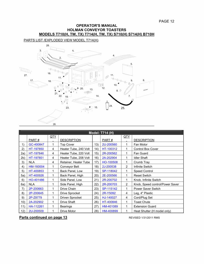
PAGE 12
OPERATOR'S MANUAL HOLMAN CONVEYOR TOASTERS
MODELS T710(H, TW, TX) T714(H, TW, TX) S710(H) S714(H) B710H PARTS LIST /EXPLODED VIEW MODEL T714(H)
1.
2.
3..
4.
5.
6.
7.
8.
9.
10.
11.
12.13.
23. 15.
16.
11.18.
19.
20.
21.22.
17.
24.25.
27.
14.
26.
1.
28.
Model: T714 (H)
PART # QTY
. DESCRIPTION PART # QTY
. DESCRIPTION 1) GC-400847 1 Top Cover 13) 2U-200560 1 Fan Motor 2) HT-197850 4 Heater Tube, 240 Volt 14) HT-100312 1 Control Box Cover 2a) HT-197846 4 Heater Tube, 220 Volt 15) 2R-200562 1 Fan Guard 2b) HT-197851 4 Heater Tube, 208 Volt 16) 2A-202904 1 Idler Shaft 3) NLA 4 Retainer, Heater Tube 17) HO-100508 1 Crumb Tray 4) HM-160004 1 Conveyor Belt 18) 2J-200538 2 Infinite Switch 5) HT-400853 1 Back Panel, Low 19) SP-118042 1 Speed Control 5a) HT-400926 1 Back Panel, High 20) 2E-200566 1 Reset Switch 6) HO-401486 1 Side Panel, Low 21) 2R-200702 1 Knob, Infinite Switch 6a) NLA 1 Side Panel, High 22) 2R-200703 2 Knob, Speed control/Power Saver 7) 2P-200663 1 Drive Chain 23) SP-115142 1 Power Saver Switch 8) 2P-200645 1 Drive Sprocket 24) 2R-Y5092 4 Leg, 4" Plastic 9) 2P-Z8779 1 Driven Sprocket 25) HJ-140027 4 Cord/Plug Set 10) 2A-202902 1 Drive Shaft 26) HT-400846 1 Toast Chute 11) HA-112261 1 Bearings 27) HM-401089 1 Extension Guard 12) 2U-200509 1 Drive Motor 28) HM-400899 1 Heat Shutter (H model only)
Parts continued on page 13 REVISED 1/31/2011 RMS
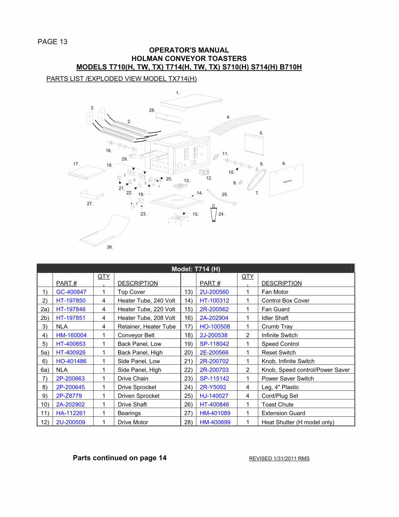
PAGE 13
OPERATOR'S MANUAL HOLMAN CONVEYOR TOASTERS
MODELS T710(H, TW, TX) T714(H, TW, TX) S710(H) S714(H) B710H PARTS LIST /EXPLODED VIEW MODEL TX714(H)
1.
2.
3..
4.
5.
6.
7.
8.
9.
10.
11.
12.13.
23. 15.
16.
29.18.
19.
20.
21.22.
17.
28.
14. 25.
24.
27.
26.
Model: T714 (H)
PART # QTY
. DESCRIPTION PART # QTY
. DESCRIPTION 1) GC-400847 1 Top Cover 13) 2U-200560 1 Fan Motor 2) HT-197850 4 Heater Tube, 240 Volt 14) HT-100312 1 Control Box Cover 2a) HT-197846 4 Heater Tube, 220 Volt 15) 2R-200562 1 Fan Guard 2b) HT-197851 4 Heater Tube, 208 Volt 16) 2A-202904 1 Idler Shaft 3) NLA 4 Retainer, Heater Tube 17) HO-100508 1 Crumb Tray 4) HM-160004 1 Conveyor Belt 18) 2J-200538 2 Infinite Switch 5) HT-400853 1 Back Panel, Low 19) SP-118042 1 Speed Control 5a) HT-400926 1 Back Panel, High 20) 2E-200566 1 Reset Switch 6) HO-401486 1 Side Panel, Low 21) 2R-200702 1 Knob, Infinite Switch 6a) NLA 1 Side Panel, High 22) 2R-200703 2 Knob, Speed control/Power Saver 7) 2P-200663 1 Drive Chain 23) SP-115142 1 Power Saver Switch 8) 2P-200645 1 Drive Sprocket 24) 2R-Y5092 4 Leg, 4" Plastic 9) 2P-Z8779 1 Driven Sprocket 25) HJ-140027 4 Cord/Plug Set 10) 2A-202902 1 Drive Shaft 26) HT-400846 1 Toast Chute 11) HA-112261 1 Bearings 27) HM-401089 1 Extension Guard 12) 2U-200509 1 Drive Motor 28) HM-400899 1 Heat Shutter (H model only)
Parts continued on page 14 REVISED 1/31/2011 RMS
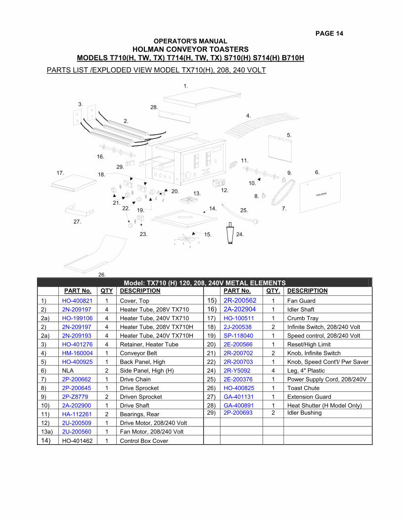
PAGE 14 OPERATOR'S MANUAL
HOLMAN CONVEYOR TOASTERS MODELS T710(H, TW, TX) T714(H, TW, TX) S710(H) S714(H) B710H
PARTS LIST /EXPLODED VIEW MODEL TX710(H), 208, 240 VOLT
1.
2.
3..
4.
5.
6.
7.
8.
9.
10.
11.
12.13.
23. 15.
16.
29.18.
19.
20.
21.22.
17.
28.
14. 25.
24.
27.
26. Model: TX710 (H) 120, 208, 240V METAL ELEMENTS
PART No. QTY DESCRIPTION PART No. QTY. DESCRIPTION 1) HO-400821 1 Cover, Top 15) 2R-200562 1 Fan Guard 2) 2N-209197 4 Heater Tube, 208V TX710 16) 2A-202904 1 Idler Shaft 2a) HO-199106 4 Heater Tube, 240V TX710 17) HO-100511 1 Crumb Tray 2) 2N-209197 4 Heater Tube, 208V TX710H 18) 2J-200538 2 Infinite Switch, 208/240 Volt 2a) 2N-209193 4 Heater Tube, 240V TX710H 19) SP-118040 1 Speed control, 208/240 Volt 3) HO-401276 4 Retainer, Heater Tube 20) 2E-200566 1 Reset/High Limit 4) HM-160004 1 Conveyor Belt 21) 2R-200702 2 Knob, Infinite Switch 5) HO-400925 1 Back Panel, High 22) 2R-200703 1 Knob, Speed Cont'l/ Pwr Saver 6) NLA 2 Side Panel, High (H) 24) 2R-Y5092 4 Leg, 4" Plastic 7) 2P-200662 1 Drive Chain 25) 2E-200376 1 Power Supply Cord, 208/240V 8) 2P-200645 1 Drive Sprocket 26) HO-400825 1 Toast Chute 9) 2P-Z8779 2 Driven Sprocket 27) GA-401131 1 Extension Guard 10) 2A-202900 1 Drive Shaft 28) GA-400891 1 Heat Shutter (H Model Only) 11) HA-112261 2 Bearings, Rear 29) 2P-200693 2 Idler Bushing
12) 2U-200509 1 Drive Motor, 208/240 Volt 13a) 2U-200560 1 Fan Motor, 208/240 Volt 14) HO-401462 1 Control Box Cover

PAGE 15
OPERATOR'S MANUAL
HOLMAN CONVEYOR TOASTERS MODELS T710(H, TW, TX) T714(H, TW, TX) S710(H) S714(H) B710H
WIRING DIAGRAM FOR MODEL T710(H & TW) 120 VOLT TX710(H) 120 VOLT
REV. 9/15/98 MJCH:\TOASTERS\T710\120VAC/WIRDIAG\T710SCM.DS4
WIRE DIAGRAMFOR MODEL T710(H), TX710(H) - 120 VOLT
PLUG CONFIGURATIONNEMA 5-15P
120 VOLT
REVISED 9/10/2008
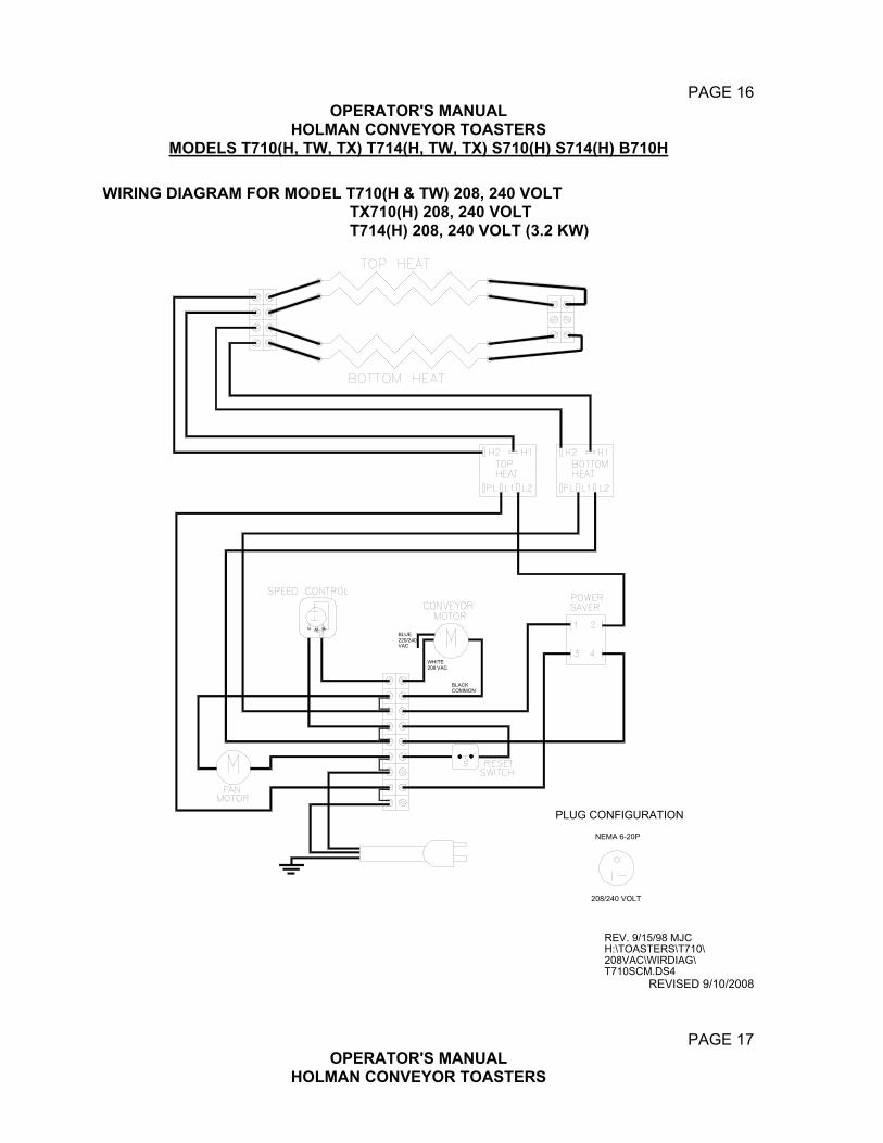
PAGE 16
OPERATOR'S MANUAL HOLMAN CONVEYOR TOASTERS
MODELS T710(H, TW, TX) T714(H, TW, TX) S710(H) S714(H) B710H WIRING DIAGRAM FOR MODEL T710(H & TW) 208, 240 VOLT TX710(H) 208, 240 VOLT T714(H) 208, 240 VOLT (3.2 KW)
REV. 9/15/98 MJCH:\TOASTERS\T710\208VAC\WIRDIAG\T710SCM.DS4
PLUG CONFIGURATION
NEMA 6-20P
208/240 VOLT
BLUE220/240VAC
WHITE208 VAC
BLACKCOMMON
REVISED 9/10/2008
PAGE 17 OPERATOR'S MANUAL
HOLMAN CONVEYOR TOASTERS

MODELS T710(H, TW, TX) T714(H, TW, TX) S710(H) S714(H) B710H
WIRING DIAGRAM FOR MODEL T714(H & TW) TX714, 3.6 kW 208, 240 VOLTS, WIRED PARELLEL
PLUG CONFIGURATION
NEMA 6-30P
REVISED 9/10/2008
PAGE 18 OPERATOR'S MANUAL
HOLMAN CONVEYOR TOASTERS MODELS T710(H, TW, TX) T714(H, TW, TX) S710(H) S714(H) B710H

WIRING DIAGRAM FOR MODEL B710(H), 120 VOLT
L1 L1L2 L2
H1 H1H2 H2
M
M
Top Heat
Bottom Heat
Top Bottom
High LimitReset
CoolingFan
SpeedControl
ConveyorMotor
Power SaverSwitch
L1 L2
1 23 4
GROUND
High LimitReset
CoolingFan
Speed
ConveyorMotor
Power SaverSwitch
120V
Plug ConfigurationNEMA 5-20P
Heat Heat
REVISED 9/10/2008
PAGE 19 OPERATOR'S MANUAL
HOLMAN CONVEYOR TOASTERS MODELS T710(H, TW, TX) T714(H, TW, TX) S710(H) S714(H) B710H
WIRING DIAGRAM FOR MODEL S710(H), 120, 208, 240 VOLT

MODEL TX710 WITH OUT POWER SAVER 120, 208, 240 VOLT
PLUG CONFIGURATIONNEMA 5-15P NEMA 6-20P
120 VOLT 208/240 VOLT REVISED 9/10/2008
PAGE 20 OPERATOR'S MANUAL
HOLMAN CONVEYOR TOASTERS MODELS T710(H, TW, TX) T714(H, TW, TX) S710(H) S714(H) B710H
WIRING DIAGRAM FOR MODEL S714(H) 208, 240 VOLT

PLUG CONFIGURATION
NEMA 6-30P
REVISED 9/10/2008