operator’s manual - skilledcrafting.com cummins dfeb,c,dfed... · the manual includes a...
TRANSCRIPT
PowerCommand Control3100 Series
Detector � Control
Generator Sets
Printed in U.S.A. 960-0102B 3-2001
Operator's Manual
ModelsDFEB, DFEC, DFED
i
Table of Contents
SECTION TITLE PAGE
IMPORTANT SAFETY INSTRUCTIONS iii. . . . . . . . . . . . . . . . . . . . . . . . . . . . . . .
1 INTRODUCTION
General 1-1. . . . . . . . . . . . . . . . . . . . . . . . . . . . . . . . . . . . . . . . . . . . . . . . . . . . . . . .
How to Obtain Service 1-2. . . . . . . . . . . . . . . . . . . . . . . . . . . . . . . . . . . . . . . . . . .
2. SPECIFICATIONS 2-1. . . . . . . . . . . . . . . . . . . . . . . . . . . . . . . . . . . . . . . . . . . . . . . . .
3 OPERATION (POWERCOMMAND CONTROL)
General 3-1. . . . . . . . . . . . . . . . . . . . . . . . . . . . . . . . . . . . . . . . . . . . . . . . . . . . . . . .
Prestart Checks 3-1. . . . . . . . . . . . . . . . . . . . . . . . . . . . . . . . . . . . . . . . . . . . . . . . .
PCC Power On / Standby Mode 3-2. . . . . . . . . . . . . . . . . . . . . . . . . . . . . . . . . . .
Front Panel 3-4. . . . . . . . . . . . . . . . . . . . . . . . . . . . . . . . . . . . . . . . . . . . . . . . . . . . .
Starting 3-5. . . . . . . . . . . . . . . . . . . . . . . . . . . . . . . . . . . . . . . . . . . . . . . . . . . . . . . .
Stopping 3-6. . . . . . . . . . . . . . . . . . . . . . . . . . . . . . . . . . . . . . . . . . . . . . . . . . . . . . .
Customer Inputs 3-6. . . . . . . . . . . . . . . . . . . . . . . . . . . . . . . . . . . . . . . . . . . . . . . . .
Menu Display and Switches 3-7. . . . . . . . . . . . . . . . . . . . . . . . . . . . . . . . . . . . . . .
Main Menu 3-8. . . . . . . . . . . . . . . . . . . . . . . . . . . . . . . . . . . . . . . . . . . . . . . . . . . . .
ENGINE Menu 3-10. . . . . . . . . . . . . . . . . . . . . . . . . . . . . . . . . . . . . . . . . . . . . . . . .
GEN Menu 3-12. . . . . . . . . . . . . . . . . . . . . . . . . . . . . . . . . . . . . . . . . . . . . . . . . . . .
ADJUST Menu 3-14. . . . . . . . . . . . . . . . . . . . . . . . . . . . . . . . . . . . . . . . . . . . . . . . .
VERSION Menu 3-16. . . . . . . . . . . . . . . . . . . . . . . . . . . . . . . . . . . . . . . . . . . . . . . . 4 TROUBLESHOOTING (POWERCOMMAND CONTROL)
Safety Considerations 4-1. . . . . . . . . . . . . . . . . . . . . . . . . . . . . . . . . . . . . . . . . . . .
Status Indicators 4-1. . . . . . . . . . . . . . . . . . . . . . . . . . . . . . . . . . . . . . . . . . . . . . . .
Resetting The Control 4-2. . . . . . . . . . . . . . . . . . . . . . . . . . . . . . . . . . . . . . . . . . . .
Status Codes Table 4-3. . . . . . . . . . . . . . . . . . . . . . . . . . . . . . . . . . . . . . . . . . . . . .
Troubleshooting Table 4-4. . . . . . . . . . . . . . . . . . . . . . . . . . . . . . . . . . . . . . . . . . . .
California
Proposition 65 WarningDiesel engine exhaust and some of its constituents are knownto the State of California to cause cancer, birth defects, andother reproductive harm.
ii
SECTION TITLE PAGE
5 OPERATION (DETECTOR CONTROL)
General 5-1. . . . . . . . . . . . . . . . . . . . . . . . . . . . . . . . . . . . . . . . . . . . . . . . . . . . . . . .
Prestart Checks 5-1. . . . . . . . . . . . . . . . . . . . . . . . . . . . . . . . . . . . . . . . . . . . . . . . .
Control Panel 5-1. . . . . . . . . . . . . . . . . . . . . . . . . . . . . . . . . . . . . . . . . . . . . . . . . . .
Generator AC Voltage Regulator 5-5. . . . . . . . . . . . . . . . . . . . . . . . . . . . . . . . . .
Engine Control Module 5-5. . . . . . . . . . . . . . . . . . . . . . . . . . . . . . . . . . . . . . . . . . .
Starting 5-6. . . . . . . . . . . . . . . . . . . . . . . . . . . . . . . . . . . . . . . . . . . . . . . . . . . . . . . .
Stopping 5-6. . . . . . . . . . . . . . . . . . . . . . . . . . . . . . . . . . . . . . . . . . . . . . . . . . . . . . .
6 TROUBLESHOOTING (DETECTOR CONTROL)
Safety Considerations 6-1. . . . . . . . . . . . . . . . . . . . . . . . . . . . . . . . . . . . . . . . . . . .
Resetting the Control 6-1. . . . . . . . . . . . . . . . . . . . . . . . . . . . . . . . . . . . . . . . . . . .
Line Circuit Breaker 6-1. . . . . . . . . . . . . . . . . . . . . . . . . . . . . . . . . . . . . . . . . . . . . .
Troubleshooting Charts 6-2. . . . . . . . . . . . . . . . . . . . . . . . . . . . . . . . . . . . . . . . . . .
7 MAINTENANCE
Maintenance 7-1. . . . . . . . . . . . . . . . . . . . . . . . . . . . . . . . . . . . . . . . . . . . . . . . . . . .
Periodic Maintenance Schedule 7-2. . . . . . . . . . . . . . . . . . . . . . . . . . . . . . . . . . .
Generator Set Inspection 7-3. . . . . . . . . . . . . . . . . . . . . . . . . . . . . . . . . . . . . . . . .
Generator Set Maintenance (Battery Disconnected) 7-4. . . . . . . . . . . . . . . . . .
Lubrication System 7-5. . . . . . . . . . . . . . . . . . . . . . . . . . . . . . . . . . . . . . . . . . . . . .
Batteries 7-6. . . . . . . . . . . . . . . . . . . . . . . . . . . . . . . . . . . . . . . . . . . . . . . . . . . . . . .
Cooling System 7-7. . . . . . . . . . . . . . . . . . . . . . . . . . . . . . . . . . . . . . . . . . . . . . . . .
Charge-Air Piping 7-7. . . . . . . . . . . . . . . . . . . . . . . . . . . . . . . . . . . . . . . . . . . . . . . .
Fuel System 7-7. . . . . . . . . . . . . . . . . . . . . . . . . . . . . . . . . . . . . . . . . . . . . . . . . . . .
Air Cleaner 7-8. . . . . . . . . . . . . . . . . . . . . . . . . . . . . . . . . . . . . . . . . . . . . . . . . . . . .
Electronic Governor 7-8. . . . . . . . . . . . . . . . . . . . . . . . . . . . . . . . . . . . . . . . . . . . . .
Exhaust Condensation Trap 7-8. . . . . . . . . . . . . . . . . . . . . . . . . . . . . . . . . . . . . . .
8 OPERATING RECOMMENDATIONS
No-Load Operation 8-1. . . . . . . . . . . . . . . . . . . . . . . . . . . . . . . . . . . . . . . . . . . . . .
Exercise Period 8-1. . . . . . . . . . . . . . . . . . . . . . . . . . . . . . . . . . . . . . . . . . . . . . . . .
Low Operating Temperatures 8-1. . . . . . . . . . . . . . . . . . . . . . . . . . . . . . . . . . . . .
High Operating Temperatures 8-1. . . . . . . . . . . . . . . . . . . . . . . . . . . . . . . . . . . . .
LS-14Miii
IMPORTANT SAFETY INSTRUCTIONS
SAVE THESE INSTRUCTIONS – This manual containsimportant instructions that should be followed duringinstallation and maintenance of the generator and batter-ies.
Before operating the generator set (genset), read theOperator’s Manual and become familiar with it and theequipment. Safe and efficient operation can beachieved only if the equipment is properly operatedand maintained. Many accidents are caused by failureto follow fundamental rules and precautions.
The following symbols, found throughout this manual,alert you to potentially dangerous conditions to the oper-ator, service personnel, or the equipment.
This symbol warns of immediatehazards which will result in severe personal in-jury or death.
WARNING This symbol refers to a hazard or un-safe practice which can result in severe person-al injury or death.
CAUTION This symbol refers to a hazard or un-safe practice which can result in personal injuryor product or property damage.
FUEL AND FUMES ARE FLAMMABLE
Fire, explosion, and personal injury or death can resultfrom improper practices.
• DO NOT fill fuel tanks while engine is running, un-less tanks are outside the engine compartment.Fuel contact with hot engine or exhaust is a potentialfire hazard.
• DO NOT permit any flame, cigarette, pilot light,spark, arcing equipment, or other ignition sourcenear the generator set or fuel tank.
• Fuel lines must be adequately secured and free ofleaks. Fuel connection at the engine should bemade with an approved flexible line. Do not use zinccoated or copper fuel lines with diesel fuel.
• Be sure all fuel supplies have a positive shutoffvalve.
• Be sure battery area has been well-ventilated priorto servicing near it. Lead-acid batteries emit a highlyexplosive hydrogen gas that can be ignited by arc-ing, sparking, smoking, etc.
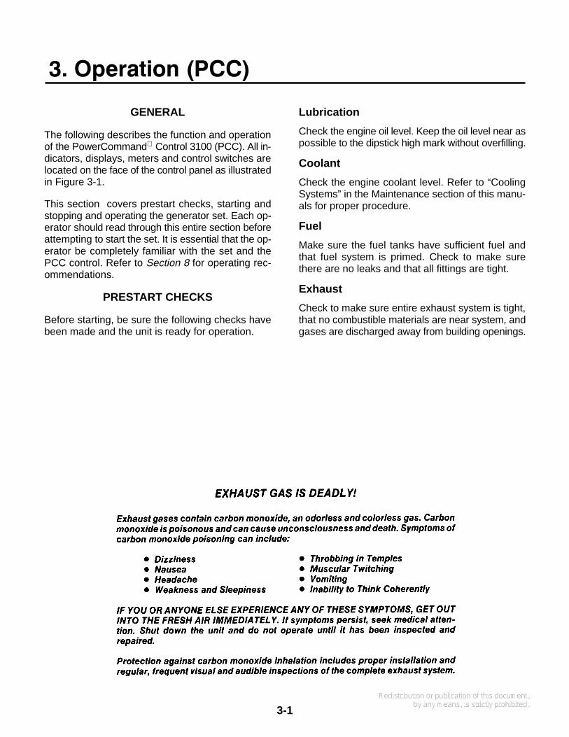
EXHAUST GASES ARE DEADLY
• Provide an adequate exhaust system to properlyexpel discharged gases away from enclosed orsheltered areas and areas where individuals arelikely to congregate. Visually and audibly inspectthe exhaust daily for leaks per the maintenanceschedule. Make sure that exhaust manifolds are se-cured and not warped. Do not use exhaust gases toheat a compartment.
• Be sure the unit is well ventilated.
• Engine exhaust and some of its constituents areknown to the state of California to cause cancer,birth defects, and other reproductive harm.
MOVING PARTS CAN CAUSE SEVEREPERSONAL INJURY OR DEATH
• Keep your hands, clothing, and jewelry away frommoving parts.
• Before starting work on the generator set, discon-nect battery charger from its AC source, then dis-connect starting batteries, negative (–) cable first.This will prevent accidental starting.
• Make sure that fasteners on the generator set aresecure. Tighten supports and clamps, keep guardsin position over fans, drive belts, etc.
• Do not wear loose clothing or jewelry in the vicinity ofmoving parts, or while working on electrical equip-ment. Loose clothing and jewelry can becomecaught in moving parts.
• If adjustment must be made while the unit is run-ning, use extreme caution around hot manifolds,moving parts, etc.
DO NOT OPERATE IN FLAMMABLE ANDEXPLOSIVE ENVIRONMENTS
Flammable vapor can cause an engine to overspeed andbecome difficult to stop, resulting in possible fire, explo-sion, severe personal injury and death. Do not operate agenset where a flammable vapor environment can becreated by fuel spill, leak, etc., unless the genset isequipped with an automatic safety device to block the airintake and stop the engine. The owners and operators ofthe genset are solely responsible for operating the gen-set safely. Contact your authorized Cummins PowerGeneration distributor for more information.
iv
ELECTRICAL SHOCK CAN CAUSESEVERE PERSONAL INJURY OR DEATH
• Remove electric power before removing protectiveshields or touching electrical equipment. Use rub-ber insulative mats placed on dry wood platformsover floors that are metal or concrete when aroundelectrical equipment. Do not wear damp clothing(particularly wet shoes) or allow skin surface to bedamp when handling electrical equipment. Do notwear jewelry. Jewelry can short out electrical con-tacts and cause shock or burning.
• Use extreme caution when working on electricalcomponents. High voltages can cause injury ordeath. DO NOT tamper with interlocks.
• Follow all applicable state and local electricalcodes. Have all electrical installations performed bya qualified licensed electrician. Tag and lock openswitches to avoid accidental closure.
• DO NOT CONNECT GENERATOR SET DIRECT-LY TO ANY BUILDING ELECTRICAL SYSTEM.Hazardous voltages can flow from the generator setinto the utility line. This creates a potential for elec-trocution or property damage. Connect onlythrough an approved isolation switch or an ap-proved paralleling device.
MEDIUM VOLTAGE GENERATOR SETS
(601V to 15kV)
• Medium voltage acts differently than low voltage.Special equipment and training is required to workon or around medium voltage equipment. Operationand maintenance must be done only by personstrained and qualified to work on such devices. Im-proper use or procedures will result in severe per-sonal injury or death.
• Do not work on energized equipment. Unauthorizedpersonnel must not be permitted near energizedequipment. Due to the nature of medium voltageelectrical equipment, induced voltage remains evenafter the equipment is disconnected from the powersource. Plan the time for maintenance with autho-rized personnel so that the equipment can be de-en-ergized and safely grounded.
GENERAL SAFETY PRECAUTIONS
• Coolants under pressure have a higher boiling pointthan water. DO NOT open a radiator or heat ex-changer pressure cap while the engine is running.Allow the generator set to cool and bleed the systempressure first.
• Used engine oils have been identified by some stateor federal agencies as causing cancer or reproduc-tive toxicity. When checking or changing engine oil,take care not to ingest, breathe the fumes, or con-tact used oil.
• Keep multi-class ABC fire extinguishers handy.Class A fires involve ordinary combustible materialssuch as wood and cloth; Class B fires, combustibleand flammable liquid fuels and gaseous fuels; ClassC fires, live electrical equipment. (ref. NFPA No. 10).
• Make sure that rags are not left on or near the en-gine.
• Make sure generator set is mounted in a manner toprevent combustible materials from accumulatingunder the unit.
• Remove all unnecessary grease and oil from theunit. Accumulated grease and oil can cause over-heating and engine damage which present a poten-tial fire hazard.
• Keep the generator set and the surrounding areaclean and free from obstructions. Remove any de-bris from the set and keep the floor clean and dry.
• Do not work on this equipment when mentally orphysically fatigued, or after consuming any alcoholor drug that makes the operation of equipment un-safe.
• Substances in exhaust gases have been identifiedby some state or federal agencies as causing can-cer or reproductive toxicity. Take care not to breathor ingest or come into contact with exhaust gases.
• Do not store any flammable liquids, such as fuel,cleaners, oil, etc., near the generator set. A fire orexplosion could result.
• Wear hearing protection when going near an oper-ating generator set.
• To prevent serious burns, avoid contact with hotmetal parts such as radiator, turbo charger and ex-haust system.
KEEP THIS MANUAL NEAR THE GENSET FOR EASY REFERENCE
1-1
1. Introduction
GENERAL
This manual covers models produced under theCummins /Onan and Cummins Power Genera-tion brand names.
Each operator should read this manual before oper-ating the set for the first time. A generator set (gen-set) must be operated and maintained properly ifyou are to expect safe, reliable and quiet operation.The manual includes a troubleshooting guide and amaintenance schedule.
The engine manual is included with the genset.Where there is conflicting information, this manualtakes precedence over the engine manual.
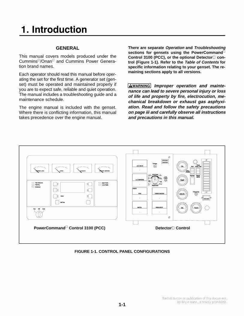
There are separate Operation and Troubleshootingsections for gensets using the PowerCommand
Control 3100 (PCC), or the optional Detector con-trol (Figure 1-1). Refer to the Table of Contents forspecific information relating to your genset. The re-maining sections apply to all versions.
WARNING Improper operation and mainte-nance can lead to severe personal injury or lossof life and property by fire, electrocution, me-chanical breakdown or exhaust gas asphyxi-ation. Read and follow the safety precautionson page iii and carefully observe all instructionsand precautions in this manual.
PowerCommand Control 3100 (PCC) Detector Control
FIGURE 1-1. CONTROL PANEL CONFIGURATIONS
1-2
HOW TO OBTAIN SERVICE
When the generator set requires servicing, contactyour nearest Cummins Power Generation distribu-tor. Factory-trained Parts and Service representa-tives are ready to handle all your service needs.
To contact your local Cummins Power Generationdistributor in the United States or Canada, call1-800-888-6626 (this automated service utilizestouch-tone phones only). By selecting Option 1(press 1), you will be automatically connected to thedistributor nearest you.
If you are unable to contact a distributor using theautomated service, consult the Yellow Pages. Typi-cally, our distributors are listed under:
GENERATORS-ELECTRIC orELECTRICAL PRODUCTS
For outside North America, call Cummins PowerGeneration, 1-763-574-5000, 7:30 AM to 4:00 PM,Central Standard Time, Monday through Friday. Or,send a fax to Cummins Power Generation using thefax number 1-763-574-8087.
When contacting your distributor, always supply thecomplete Model, Specification, and Serial Numberas shown on the generator set nameplate.
WARNING
INCORRECT SERVICE OR PARTS REPLACEMENT CAN RESULT IN SEVERE PERSONAL IN-JURY, DEATH, AND/OR EQUIPMENT DAMAGE. SERVICE PERSONNEL MUST BE TRAINEDAND EXPERIENCED TO PERFORM ELECTRICAL AND/OR MECHANICAL SERVICE.
Copyright 2001 Cummins Power Generation. All rights reserved.
Cummins, Onan and PowerCommand are registered trademarks of Cummins Inc.
Detector is a trademark of Cummins Inc.
2-1
2. Specifications
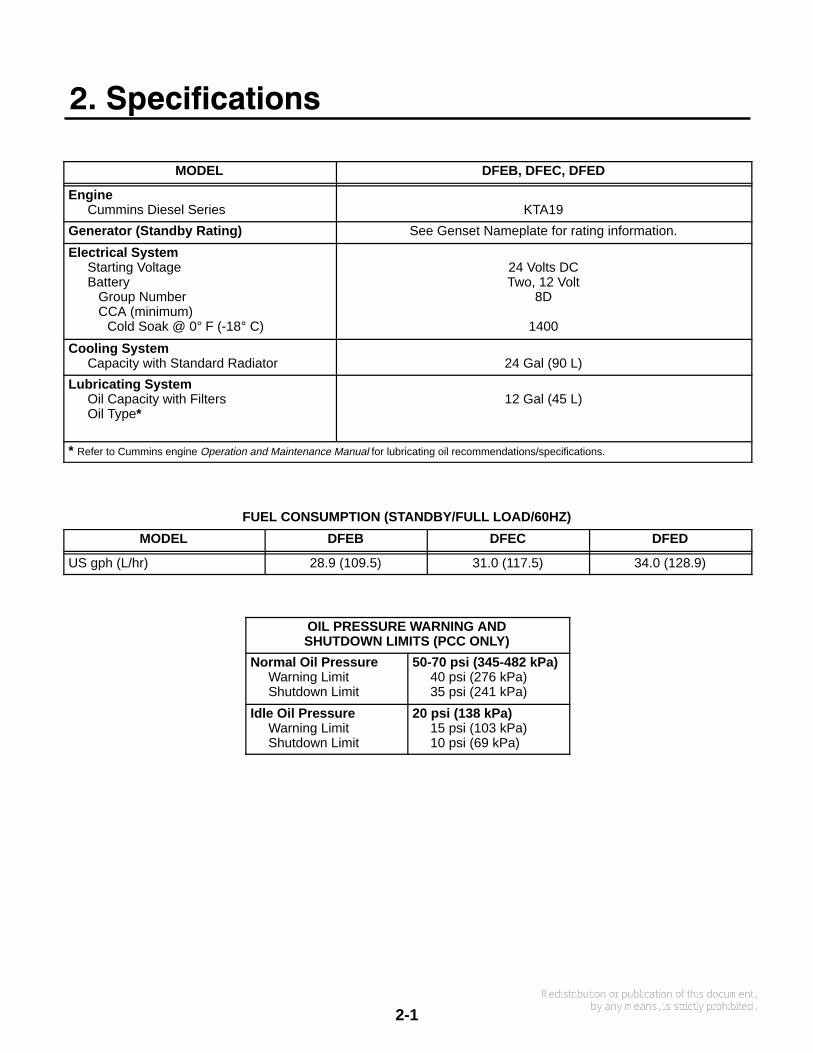
MODEL DFEB, DFEC, DFED
EngineCummins Diesel Series KTA19
Generator (Standby Rating) See Genset Nameplate for rating information.
Electrical SystemStarting VoltageBattery
Group NumberCCA (minimum)
Cold Soak @ 0° F (-18° C)
24 Volts DCTwo, 12 Volt
8D
1400
Cooling SystemCapacity with Standard Radiator 24 Gal (90 L)
Lubricating SystemOil Capacity with FiltersOil Type*
12 Gal (45 L)
* Refer to Cummins engine Operation and Maintenance Manual for lubricating oil recommendations/specifications.
FUEL CONSUMPTION (STANDBY/FULL LOAD/60HZ)
MODEL DFEB DFEC DFED
US gph (L/hr) 28.9 (109.5) 31.0 (117.5) 34.0 (128.9)
OIL PRESSURE WARNING ANDSHUTDOWN LIMITS (PCC ONLY)
Normal Oil PressureWarning LimitShutdown Limit
50-70 psi (345-482 kPa)40 psi (276 kPa)35 psi (241 kPa)
Idle Oil PressureWarning LimitShutdown Limit
20 psi (138 kPa)15 psi (103 kPa)10 psi (69 kPa)

2-2
THIS PAGE LEFT INTENTIONALLY BLANK
3-1
3. Operation (PCC)
GENERAL
The following describes the function and operationof the PowerCommand Control 3100 (PCC). All in-dicators, displays, meters and control switches arelocated on the face of the control panel as illustratedin Figure 3-1.
This section covers prestart checks, starting andstopping and operating the generator set. Each op-erator should read through this entire section beforeattempting to start the set. It is essential that the op-erator be completely familiar with the set and thePCC control. Refer to Section 8 for operating rec-ommendations.
PRESTART CHECKS
Before starting, be sure the following checks havebeen made and the unit is ready for operation.
Lubrication
Check the engine oil level. Keep the oil level near aspossible to the dipstick high mark without overfilling.
Coolant
Check the engine coolant level. Refer to “CoolingSystems” in the Maintenance section of this manu-als for proper procedure.
Fuel
Make sure the fuel tanks have sufficient fuel andthat fuel system is primed. Check to make surethere are no leaks and that all fittings are tight.
Exhaust
Check to make sure entire exhaust system is tight,that no combustible materials are near system, andgases are discharged away from building openings.
3-2
PCC POWER ON / STANDBY MODE
The control panel can be set to function in one of thefollowing modes; Power On or Standby.
To select the alternate mode, refer to the Installationmanual.
Power On Mode: In this mode, power is continu-ously supplied to the control panel. The control’soperating software and control panel LED’s/displaywill remain active.
Standby Mode: In this mode, the control’s operat-ing software is inactive and the LED’s and displayson the front panel are all off. The operating softwareis initialized and the front panel is turned on in re-sponse to one of the following:
• moving the Run/Off/Auto switch to the Runposition,
• pressing the Self Test button,
• a remote start input signal (generator set inAuto mode), or
• any one of several “wake-up” signals from ex-ternal switches.
The wake up signals are:
Low Engine Coolant LevelLow Engine Coolant TemperatureLow FuelCustomer Fault Inputs 2 and 3Run Selected on Run/Off Auto SwitchRemote Start Signal in Auto ModeEmergency Stop
With the switch set to Standby mode, pressing theSelf Test button will allow you to activate and viewthe menu displays without starting the generatorset. If no menu selections are made, a software tim-er will shut down the power after 30 seconds.
When left in the Standby mode, and a “Warning”signal is sensed by the PCC (for example, low cool-ant temp), the control will wake up and display thewarning message. The control will remain activeuntil the warning condition is corrected and the Re-set button is pressed to clear the warning message.
3-3
ACTIVE SWITCHINDICATOR
(1 of 6)
UPPER AND LOWERSCALE INDICATOR
FREQUENCYMETER
KILOWATTMETER
(PERCENT LOAD)
PHASE SELECTORSWITCH ANDINDICATORS
RUN/OFF/AUTOSWITCH
RESETSWITCH
NON�AUTOMATICWARNING
SHUTDOWN STATUS INDICATORS
EMERGENCYSTOP PUSH
BUTTON
PANEL LAMPSWITCH
SELF TESTSWITCH
MENUSWITCH
ACVOLTMETER
AC AMMETER
ALPHANUMERICDISPLAY
MENUSELECTION
SWITCH (1 of 4)
PCC 3100LABEL
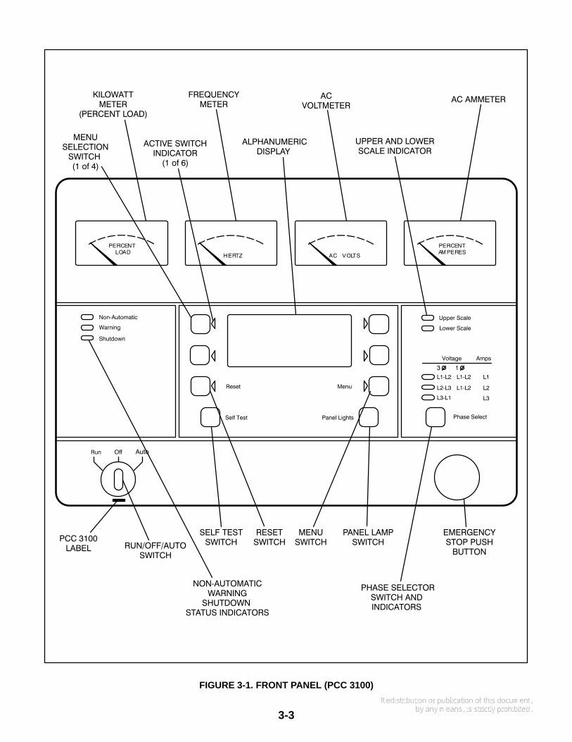
FIGURE 3-1. FRONT PANEL (PCC 3100)

3-4
FRONT PANEL
Figure 3-1 shows the features of the front panel.
AC Voltmeter: Dual scale instrument indicates ACvoltage. Measurement scale in use is shown onscale indicator lamp.
AC Ammeter: Indicates current output in percent ofmaximum rated current.
Kilowatt Meter: Indicates 3-phase AC power out-put as percent of rated load.
Frequency Meter: Indicates generator output fre-quency in hertz.
Upper and Lower Scale Indicator Lamps: Indi-cate AC voltmeter scale.
Digital Display: This two-line, 16-character per linealphanumeric display is used in the menu-drivenoperating system, in conjunction with the displaymenu selection switches and the Menu switch. Re-fer to the menu trees later in this section. The dis-play is also used to show warning and shutdownmessages.
Display Menu Selection Switches: Four momen-tary switches—two on each side of the digital dis-play window—are used to step through the variousmenu options and to adjust generator set parame-ters. The green arrow adjacent to the switch is litwhen the switch can be used (switch is “active”).
Menu Switch: Press this switch to return the digitaldisplay to the MAIN MENU. Refer to the menu treeslater in this section.
Reset Switch: Press this switch to reset warningand shutdown messages after the condition hasbeen corrected. To reset a shutdown message withthe Reset switch, the Run/Off/Auto switch must bein the Off position.
In Auto mode, shutdown faults can be reset by re-moving the remote start input and then cycling theremote reset input.
Self Test Switch: Press and hold this switch to lightall front panel LEDs and cycle through all shutdownand warning messages.
Panel Lights Switch: Press this switch to turn con-trol panel illumination on and off. The illuminationwill shut off after about eight minutes.
Phase Selector Switch and Indicators: Press thismomentary switch to select phases of generatoroutput to be measured by AC voltmeter and amme-ter. LEDs indicate the selected phase.
Run/Off/Auto Switch: This switch starts and stopsthe set locally, or enables start/stop control of theengine from a remote location. (Ground to start.)
Emergency Stop Button: Push the switch in foremergency shutdown of the engine.
To reset:Pull the button out or turn the button clockwise(button with arrow) and allow it to pop out. Movethe Run/Off/Auto switch to Off. Press the front panel Reset switch.Select Run or Auto, as required.
Non-Automatic Status Indicator: This red lampflashes continuously when the Run/Off/Auto switchis not in the Auto position.
Warning Status Indicator: This yellow lamp is litwhenever the control detects a warning condition.After the condition is corrected, warning indicatorscan be reset by pressing the Reset switch. (It is notnecessary to stop the generator set.) In auto mode,warning indicators can also be reset by cycling theremote reset input after the condition is corrected.
Shutdown Status Indicator: This red lamp is litwhenever the control detects a shutdown condition.After the condition is corrected, shutdown indica-tors can be reset by turning the Run/Off/Auto switchto the Off position, and pressing the Reset switch. Inauto mode, shutdown faults can be reset by remov-ing the remote start input and then cycling the re-mote reset input.
Emergency Stop shutdown status (Code 102) can bereset only at the PCC front panel.

3-5
STARTING
The following sections cover the three systemsused to start the generator set.
Before starting the generator set, make sure thatexhaust and fuel fittings are tight and properly posi-tioned and that proper maintenance has been per-formed. See Prestart Checks in this section.
Starting at Control Panel
Move the Run/Off/Auto switch to the Run position.This will activate the engine control system and thestarting system. The starter will begin cranking, andafter a few seconds the engine will start and thestarter will disconnect.
If the engine does not start, the starter will disen-gage after a specified period of time and the controlwill indicate an overcrank shutdown.
Generator sets with the cycle cranking option se-lected will alternately crank and rest for 3, 4, or 5cycles. The crank times and rest times can be indi-vidually preset for 7 to 20 seconds.
To change the cycle number, and the crank and resttimes, contact an authorized service center.
Generator sets with the cycle cranking option notselected will crank continuously for up to 75 sec-onds before disengaging the starter.
To clear an overcrank shutdown, place the Run/Off/Auto switch in the Off position and momentarilypress the Reset switch. Wait two minutes for thestarter motor to cool and then repeat the startingprocedure. If the engine does not run after a secondattempt, refer to the Troubleshooting section.
Starting from Remote Location
Place the Run/Off/Auto switch in the Auto position.This allows the generator set to be started from a re-mote switch.
The operating software is initialized and the frontpanel is turned on in response to a remote run sig-nal. Closing the remote switch initiates the startingsequence described in the previous section.
Starter cranking will begin after the start time delaytimer (0–300 seconds) has timed out. Refer to TimeDelay Start in the Adjust menu.
Automatic Starting from ATS
Place the Run/Off/Auto switch in the Auto position ifan automatic transfer switch (ATS) is used. The op-erating software is initialized in response to a re-mote run signal from the transfer switch. This allowsthe transfer switch to start the generator set if a pow-er outage occurs and stop it when the power re-turns.
Starter cranking will begin after the start time delaytimer (0–300 seconds) has timed out. Refer to TimeDelay Start in the Adjust menu.
Cold Starting with Loads
In accordance with NFPA 110, Cummins PowerGeneration recommends installing diesel standbygenerator sets (life safety systems) equipped withcoolant heaters in locations where the minimumambient temperature is above 40°F (4°C). NFPAalso requires that the engine coolant be maintainedat a minimum of 90°F (32°C) and for most applica-tions, accept the emergency load in 10 seconds orless. Although most generator sets will start in tem-peratures down to –25°F (–32°C) when equippedwith coolant heaters, it might take more than 10 sec-onds to warm the engine up before a load can be ap-plied when ambient temperatures are below 40°F(4°C).
The Low Coolant Temp (Code 210) message, inconjunction with illumination of the Warning LED, isprovided to meet the requirements of NFPA 110.The low coolant temperature sensing logic initiatesa warning when the engine coolant temperaturefalls below 70°F (21°C). In applications where theambient temperature falls below 40°F (4°C), LowCoolant Temp may be indicated even though thecoolant heaters are connected and functioningproperly. Under these conditions, although the gen-erator set may start, it may not be able to acceptload within 10 seconds. When this condition occurs,check the coolant heaters for proper operation. Ifthe coolant heaters are operating properly, otherprecautions may be necessary to warm the enginebefore applying a load.
3-6
STOPPING
Before Stopping
Run the generator set at no load for three to fiveminutes before stopping. This allows the lubricatingoil and engine coolant to carry heat away from thecombustion chamber and bearings.
Stopping at Control Panel
If the set was started at the set control panel, movethe Run/Off/Auto switch to the Off position. The setwill stop immediately. The control will respond to“wake up” signals from the external sensingswitches when the Run/Off/Auto switch is in the Offposition.
Stopping from Remote Location
Move the remote starting switch to the Off position.
The set will stop after the stop time delay timer(0–600 seconds) has timed out. Refer to Time DelayStop in the Adjust menu.
Automatic Stopping from ATS
If the set was started by an automatic transferswitch, the transfer switch control will send a remotestop signal after the normal power source returns.
The set will stop after the stop time delay timer(0–600 seconds) has timed out. Refer to Time DelayStop in the Adjust menu.
Emergency Stop (Code 102)
The emergency stop button is located on the lowerright side of control panel (Figure 3-1). Push the but-ton in for emergency stop. The red Shutdown statusLED will light, and the digital display message willbe: “EMERGENCY STOP
102 – SHUTDOWN”
To reset, pull the button out or turn the button clock-wise (button with arrow) and allow it to pop out.Move the Run/Off/Auto switch to the Off position.Then momentarily push the Reset switch.
Emergency Stop shutdown status can be reset onlyat the PCC front panel.
CUSTOMER INPUTS
Remote Start Input: When the Run/Off/Autoswitch is in the Auto position, selecting this input ini-tiates the engine cranking and start sequence.
Remote Reset Input: When the Run/Off/Autoswitch is in the Auto position and the remote startswitch is open, selecting this input resets anylatched shutdown fault (except Emergency Stop,which must be reset at the front panel.)
Engine Idle Input: When the set is operating in theRUN mode, selecting this input causes generatorbuild up to be inhibited and the engine to be gov-erned at 800 RPM. When ground is removed fromthis input, the set returns to normal speed and volt-age.
Engine idle operation is applicable only in the RUNmode. The PCC operating program does not permitengine idle operation when the set is operating inAUTO mode.
When the engine idle function is enabled, the con-trol automatically sets lower oil pressure warningand shutdown trip points to reflect the lower operat-ing speed. When the engine idle function is re-moved and the set reverts to normal operatingspeed, the control automatically resets oil pressurewarning and shutdown trip points to the normal set-tings.
Remote Emergency Stop Input: Grounding thisinput causes an immediate shutdown. Emergencystop must be reset at the front panel.
3-7
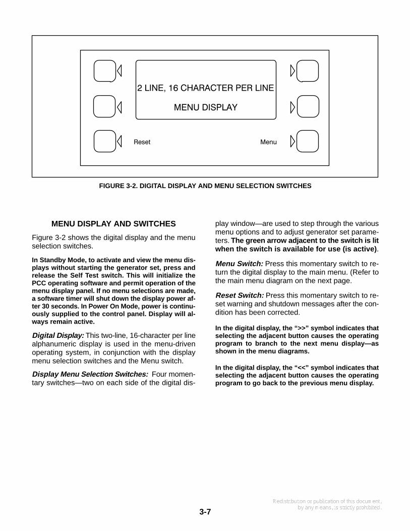
FIGURE 3-2. DIGITAL DISPLAY AND MENU SELECTION SWITCHES
MENU DISPLAY AND SWITCHES
Figure 3-2 shows the digital display and the menuselection switches.
In Standby Mode, to activate and view the menu dis-plays without starting the generator set, press andrelease the Self Test switch. This will initialize thePCC operating software and permit operation of themenu display panel. If no menu selections are made,a software timer will shut down the display power af-ter 30 seconds. In Power On Mode, power is continu-ously supplied to the control panel. Display will al-ways remain active.
Digital Display: This two-line, 16-character per linealphanumeric display is used in the menu-drivenoperating system, in conjunction with the displaymenu selection switches and the Menu switch.
Display Menu Selection Switches: Four momen-tary switches—two on each side of the digital dis-
play window—are used to step through the variousmenu options and to adjust generator set parame-ters. The green arrow adjacent to the switch is litwhen the switch is available for use (is active) .
Menu Switch: Press this momentary switch to re-turn the digital display to the main menu. (Refer tothe main menu diagram on the next page.
Reset Switch: Press this momentary switch to re-set warning and shutdown messages after the con-dition has been corrected.
In the digital display, the “>>” symbol indicates thatselecting the adjacent button causes the operatingprogram to branch to the next menu display—asshown in the menu diagrams.
In the digital display, the “<<” symbol indicates thatselecting the adjacent button causes the operatingprogram to go back to the previous menu display.
3-8
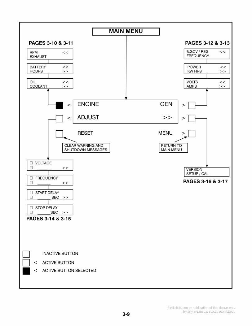
MAIN MENU
The facing page shows the main menu and a blockrepresentation of the available submenus.
As shown in the diagram, the main menu canbranch into one of four directions.
To display engine parameters, such as oil pressureand temperature, water temperature, engine speed(RPM), and exhaust temperature, press the buttonnext to the word “ENGINE” in the display. Turn to theENGINE menu diagram on page 3-11.
To display generator parameters, such as volts,amps, power (kW), and frequency, press the button
next to the word “GEN” in the display. Turn to theGEN menu diagram on page 3-13.
To adjust output voltage and frequency, or start andstop delays, press the button next to the word “AD-JUST” in the display. Turn to the ADJUST menu dia-gram on page 3-15.
To display the selected generator set model and theresident version software, press the button next tothe “>>” in the display. From this selection, you canalso review a History file that can record and saveup to 20 error messages. Turn to the VERSIONmenu diagram on page 3-17.
3-9
⇑ VOLTAGE
⇓ _______ >>
< >
< >
ENGINE GEN
ADJUST >>
< ACTIVE BUTTON
< ACTIVE BUTTON SELECTED
INACTIVE BUTTON
RESET MENU >
RETURN TO MAIN MENU
CLEAR WARNING ANDSHUTDOWN MESSAGES
PAGES 3�10 & 3�11
MAIN MENU
VERSIONSETUP / CAL
PAGES 3�12 & 3�13
PAGES 3�14 & 3�15
OIL <<COOLANT >>
BATTERY <<HOURS >>
RPM <<EXHAUST
⇑ FREQUENCY
⇓ _______ >>
⇑ START DELAY
⇓ _______ SEC >>
⇑ STOP DELAY
⇓ _______SEC >>
VOLTS <<AMPS >>
POWER <<KW HRS >>
%GOV / REG <<FREQUENCY
PAGES 3�16 & 3�17
3-10
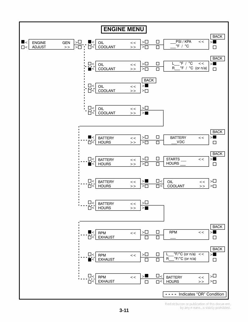
ENGINE MENU
The facing page shows a block representation ofthe ENGINE menu. If you press the button next tothe word “ENGINE” in the display, the first ENGINEsubmenu will appear.
As shown in the diagram, the ENGINE menu hasthree submenus.
OIL/COOLANT submenu: This is the first subme-nu. Select OIL for a display of oil pressure and oiltemperature. Select COOLANT for a display ofcoolant temperature. When oil or coolant parame-ters are displayed, pressing the button next to the“<<” will return the display (“BACK”) to the OIL/COOLANT submenu.
To check oil pressure or coolant temperature duringa warning, access the oil pressure or coolant temper-ature menu prior to clearing the fault.
BATTERY/HOURS submenu: From the OIL/COOLANT submenu, press the button next to the“>>” in the display to move to the BATTERY/HOURS submenu. Select BATTERY for a display ofbattery voltage. Select HOURS for a display of thenumber of starts and the running hours. When bat-tery or hours parameters are displayed, pressingthe button next to the “<<” will return the display(“BACK”) to the BATTERY/HOURS submenu.
RPM/EXHAUST submenu: From the BATTERY/HOURS submenu, press the button next to the “>>”in the display to move to the RPM/EXHAUST sub-menu. Select RPM for a display of engine RPM. Se-lect EXHAUST for a display of the (optional) ex-haust temperature. When RPM or exhaust parame-ters are displayed, pressing the button next to the“<<” will return the display (“BACK”) to the RPM/EX-HAUST submenu.
3-11
< >
< >
< >
< >
>L___°F / °C <<
R___°F / °C (or n/a)
>
>
>
< >
< >
< >
< >BATTERY <<HOURS >>
>
< >
< >
< >ENGINE GENADJUST >>
< >
< >OIL <<COOLANT >>
< > ___PSI / KPA <<
___°F / °C
< >OIL <<COOLANT >>
< >
< >OIL <<COOLANT >>
OIL <<COOLANT >>
< >
>
< >BATTERY <<HOURS >>
BATTERY << ___V
STARTS ___ <<HOURS ___
< >
< >BATTERY <<HOURS >>
< >BATTERY <<HOURS >>
L___°F/°C (or n/a) <<
R___°F/°C (or n/a)
<RPM <<EXHAUST
< >
<RPM <<EXHAUST
< >
<RPM <<EXHAUST
RPM << ___
BATTERY <<HOURS >>< >
BACK
BACK
BACK
BACK
BACK
BACK
ENGINE MENU
OIL <<COOLANT >>
DC
Indicates �OR" Condition
BACK
3-12
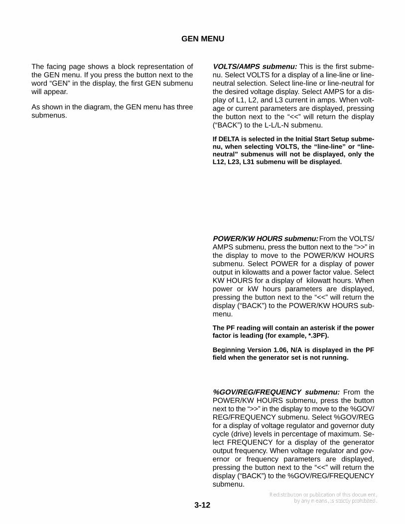
GEN MENU
The facing page shows a block representation ofthe GEN menu. If you press the button next to theword “GEN” in the display, the first GEN submenuwill appear.
As shown in the diagram, the GEN menu has threesubmenus.
VOLTS/AMPS submenu: This is the first subme-nu. Select VOLTS for a display of a line-line or line-neutral selection. Select line-line or line-neutral forthe desired voltage display. Select AMPS for a dis-play of L1, L2, and L3 current in amps. When volt-age or current parameters are displayed, pressingthe button next to the “<<” will return the display(“BACK”) to the L-L/L-N submenu.
If DELTA is selected in the Initial Start Setup subme-nu, when selecting VOLTS, the “line-line” or “line-neutral” submenus will not be displayed, only theL12, L23, L31 submenu will be displayed.
POWER/KW HOURS submenu: From the VOLTS/AMPS submenu, press the button next to the “>>” inthe display to move to the POWER/KW HOURSsubmenu. Select POWER for a display of poweroutput in kilowatts and a power factor value. SelectKW HOURS for a display of kilowatt hours. Whenpower or kW hours parameters are displayed,pressing the button next to the “<<” will return thedisplay (“BACK”) to the POWER/KW HOURS sub-menu.
The PF reading will contain an asterisk if the powerfactor is leading (for example, *.3PF).
Beginning Version 1.06, N/A is displayed in the PFfield when the generator set is not running.
%GOV/REG/FREQUENCY submenu: From thePOWER/KW HOURS submenu, press the buttonnext to the “>>” in the display to move to the %GOV/REG/FREQUENCY submenu. Select %GOV/REGfor a display of voltage regulator and governor dutycycle (drive) levels in percentage of maximum. Se-lect FREQUENCY for a display of the generatoroutput frequency. When voltage regulator and gov-ernor or frequency parameters are displayed,pressing the button next to the “<<” will return thedisplay (“BACK”) to the %GOV/REG/FREQUENCYsubmenu.

3-13
<
< >
< >
< > < >
< >
< >< >
< >
< >
< > < >
< >
< >
< >
<
< >
>< >
<< >
ENGINE GENADJUST >>< >
VOLTS <<AMPS >>
L - L <<L - N
>
L12 L23 L31 <<___ ___ ___
L1N L2N L3N <<___ ___ ___
BACK
BACK
<
BACK
< >
< >VOLTS <<AMPS >>
>L1 L2 L3 <<___ ___ ___
BACK
VOLTS <<AMPS >>
ENGINE GENADJUST >>< >
VOLTS <<AMPS >>
POWER <<KW HRS >>
> ___ KW << ___ PF
BACK
< >
< >POWER <<KW HRS >>
> KW HRS << ____________
BACK
< >POWER <<KW HRS >>
POWER <<KW HRS >>
%GOV / REG <<FREQUENCY
BACK
< >
<
%GOV / REG <<FREQUENCY
< >
<
%GOV / REG <<FREQUENCY
> GOVERNOR_ % << REGULATOR_ %
> FREQUENCY << ___ HZ
BACK
BACK
BACK
GEN MENU
L - L <<L - N
L - L <<L - N
Indicates �OR" Condition
3-14
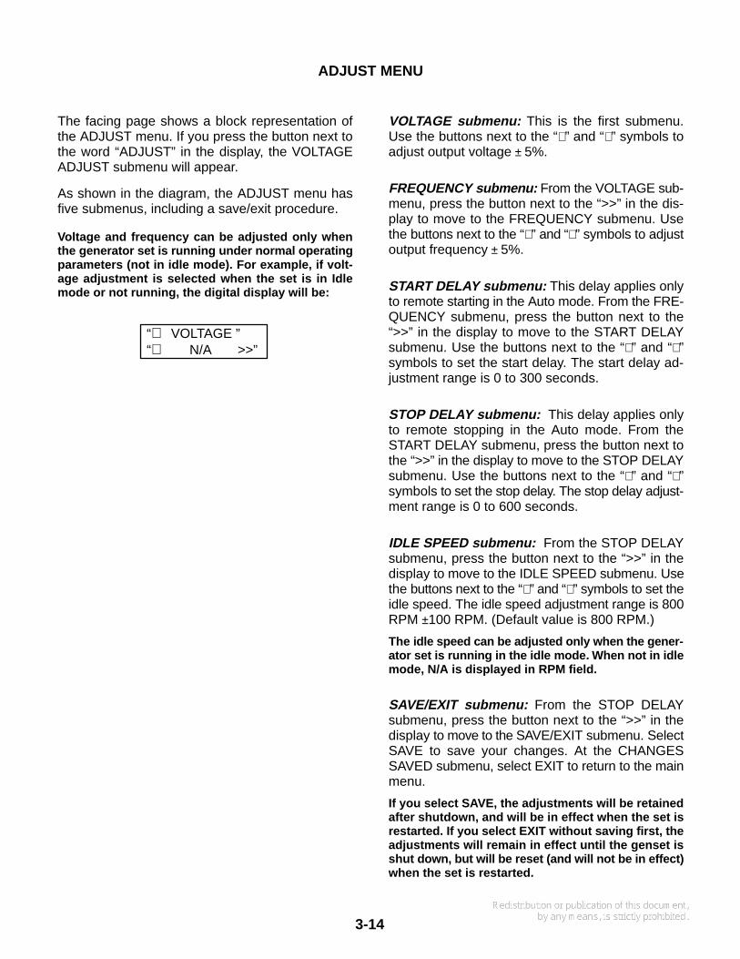
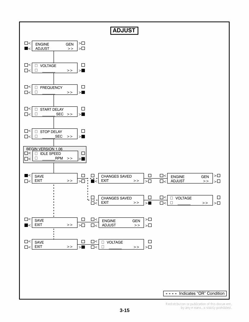
ADJUST MENU
The facing page shows a block representation ofthe ADJUST menu. If you press the button next tothe word “ADJUST” in the display, the VOLTAGEADJUST submenu will appear.
As shown in the diagram, the ADJUST menu hasfive submenus, including a save/exit procedure.
Voltage and frequency can be adjusted only whenthe generator set is running under normal operatingparameters (not in idle mode). For example, if volt-age adjustment is selected when the set is in Idlemode or not running, the digital display will be:
“⇑ VOLTAGE ” “⇓ N/A >>”
VOLTAGE submenu: This is the first submenu.Use the buttons next to the “⇑ ” and “⇓ ” symbols toadjust output voltage ± 5%.
FREQUENCY submenu: From the VOLTAGE sub-menu, press the button next to the “>>” in the dis-play to move to the FREQUENCY submenu. Usethe buttons next to the “⇑ ” and “⇓ ” symbols to adjustoutput frequency ± 5%.
START DELAY submenu: This delay applies onlyto remote starting in the Auto mode. From the FRE-QUENCY submenu, press the button next to the“>>” in the display to move to the START DELAYsubmenu. Use the buttons next to the “⇑ ” and “⇓ ”symbols to set the start delay. The start delay ad-justment range is 0 to 300 seconds.
STOP DELAY submenu: This delay applies onlyto remote stopping in the Auto mode. From theSTART DELAY submenu, press the button next tothe “>>” in the display to move to the STOP DELAYsubmenu. Use the buttons next to the “⇑ ” and “⇓ ”symbols to set the stop delay. The stop delay adjust-ment range is 0 to 600 seconds.
IDLE SPEED submenu: From the STOP DELAYsubmenu, press the button next to the “>>” in thedisplay to move to the IDLE SPEED submenu. Usethe buttons next to the “⇑ ” and “⇓ ” symbols to set theidle speed. The idle speed adjustment range is 800RPM ±100 RPM. (Default value is 800 RPM.)
The idle speed can be adjusted only when the gener-ator set is running in the idle mode . When not in idlemode, N/A is displayed in RPM field.
SAVE/EXIT submenu: From the STOP DELAYsubmenu, press the button next to the “>>” in thedisplay to move to the SAVE/EXIT submenu. SelectSAVE to save your changes. At the CHANGESSAVED submenu, select EXIT to return to the mainmenu.
If you select SAVE, the adjustments will be retainedafter shutdown, and will be in effect when the set isrestarted. If you select EXIT without saving first, theadjustments will remain in effect until the genset isshut down, but will be reset (and will not be in effect)when the set is restarted.
3-15
< >< >
< >
< >
< >
< >
<
<
< >
<
< >
ENGINE GENADJUST >>
< >
< >
⇑ VOLTAGE
⇓ _______ >>
<
⇑ FREQUENCY
⇓ _______ >>
⇑ START DELAY
⇓ _______ SEC >>
⇑ STOP DELAY
⇓ _______SEC >>
< SAVEEXIT >>
< SAVEEXIT >>
< >
< SAVEEXIT >>
< >
CHANGES SAVEDEXIT >>
CHANGES SAVEDEXIT >>
< ⇑ VOLTAGE
⇓ _______ >>
ENGINE GENADJUST >>
< >
< >
< >
< ⇑ VOLTAGE
⇓ _______ >>
ENGINE GENADJUST >>
< >
< >
ADJUST
< >
< ⇑ IDLE SPEED
⇓ _______RPM >>
BEGIN VERSION 1.06
Indicates �OR" Condition

3-16
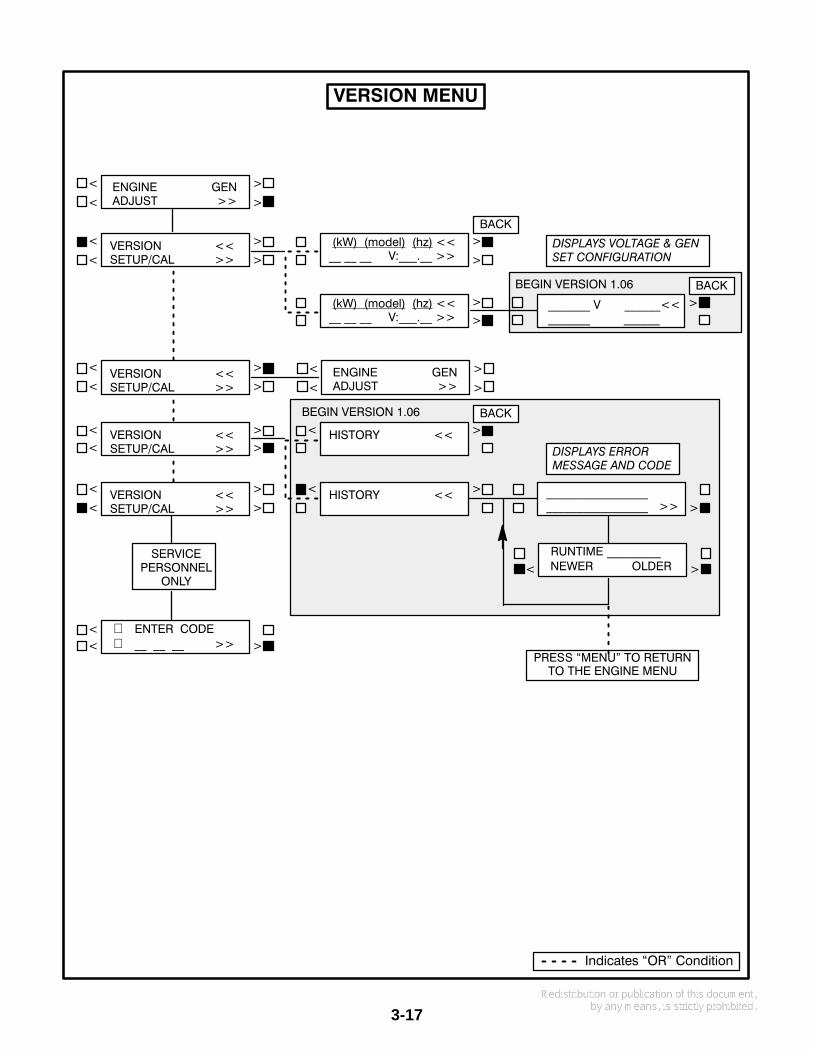
VERSION MENU
The facing page shows a block representation ofthe VERSION submenus. If you press the buttonnext to the “>>” in the Main menu display, the VER-SION/SETUP/CAL menu will appear.
VERSION submenu: If you select VERSION, thedisplay will show the generator set model number,frequency, and kW rating, and the date and versionof the operating software.
To display the generator set configuration options,press the button next to the “>>” in the submenu thatdisplays the model number, frequency and etc. Thismenu provides the following information:
• Generator set voltage• WYE or DELTA• Standby or Prime• Parallel or Single
HISTORY: (Beginning Version 1.06) From the VER-SION menu, press the button next to the “>>” in thedisplay to move to the HISTORY submenu. Pressthe button next to “HISTORY” to display the last (lat-est) recorded error message.
The software will record (save) up to 20 error mes-sages. The last error detected will always be dis-played first. As each new error is detected, the old-est error recorded after 20 will be deleted.
To view the generator set runtime at which the erroroccurred and to scroll through the remaining re-corded errors, press the button next to the “>>” inthe error message menu to display the RUNTIME,NEWER/OLDER menu.
The buttons next to NEWER and OLDER are usedto scroll up and down through the error messages.For example, pressing OLDER will display the nextoldest recorded error message.
3-17
< >
< >
ENGINE GENADJUST >>
< >
< ⇑ ENTER CODE
⇓ __ __ __ >>
VERSION MENU
< >
< >VERSION <<SETUP/CAL >>
< >
>
>
(kW) (model) (hz) <<__ __ __ V:___.__ >>
BACK
ENGINE GENADJUST >>
< >
< >
< >VERSION <<SETUP/CAL >>
< >
< >VERSION <<SETUP/CAL >>
>
>
(kW) (model) (hz) <<__ __ __ V:___.__ >>
_______ V ______<<_______ ______
>
BACK
< >
< >VERSION <<SETUP/CAL >>
< >HISTORY <<
BACK
< >HISTORY <<
>
__________________________________ >>
< >
RUNTIME _________
NEWER OLDER
DISPLAYS ERROR
MESSAGE AND CODE
BEGIN VERSION 1.06
BEGIN VERSION 1.06
DISPLAYS VOLTAGE & GEN
SET CONFIGURATION
SERVICEPERSONNEL
ONLY
Indicates �OR" Condition
PRESS �MENU" TO RETURNTO THE ENGINE MENU

3-18
THIS PAGE LEFT INTENTIONALLY BLANK
4-1
4. Troubleshooting (PCC)
The PowerCommand Control 3100 (PCC) contin-uously monitors engine sensors for abnormal con-ditions, such as low oil pressure and high coolanttemperature. If any of these conditions occur, thePCC will light a yellow Warning lamp or a red Shut-down lamp and display a message on the digital dis-play panel.
In the event of a shutdown fault (red Shutdownlamp), the PCC will stop the engine and close a setof contacts that can be wired to trip a circuit breaker.If the generator set is stopped for this reason, theoperator can restart the set after making adjust-ments or corrections. This section lists the warningand shutdown messages (Table 4-1), and suggeststroubleshooting procedures (Table 4-2).
Specifications section lists the PCC oil pressurewarning and shutdown limits.
SAFETY CONSIDERATIONS
WARNING Contacting high voltage compo-nents can cause electrocution, resulting in se-vere personal injury or death. Keep the outputbox covers in place during troubleshooting.
High voltages are present when the set is running.Do not open the generator output box while the setis running.
WARNING Ignition of explosive battery gasescan cause severe personal injury or death. Arc-ing at battery terminals, light switch or otherequipment, flame, pilot lights and sparks can ig-nite battery gas. Do not smoke, or switchtrouble light ON or OFF near battery. Dischargestatic electricity from body before touching bat-teries by first touching a grounded metal sur-face.
Ventilate battery area before working on or nearbattery—Wear goggles—Stop genset and dis-connect charger before disconnecting batterycables—Disconnect negative (–) cable first andreconnect last.
CAUTION Disconnect battery charger from ACsource before disconnecting battery cables.Otherwise, disconnecting cables can result involtage spikes damaging to DC control circuitsof the set.
WARNING Accidental starting of the generatorset can cause severe personal injury or death.Prevent accidental starting by disconnectingthe negative (–) cable from the battery terminal.
When troubleshooting a set that is shut down, makecertain the generator set cannot be accidentally re-started as follows:
1. Move the Run/Off/Auto switch on the controlpanel to the OFF position.
2. Turn off or remove AC power from the batterycharger.
3. Remove the negative (–) battery cable from thegenerator set starting battery.
When a fault condition occurs during operation, fol-low the procedures listed below to locate and cor-rect the problem. For any symptom not listed, con-tact an authorized service center for assistance.
4-2
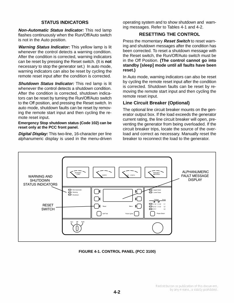
STATUS INDICATORS
Non-Automatic Status Indicator: This red lampflashes continuously when the Run/Off/Auto switchis not in the Auto position.
Warning Status Indicator: This yellow lamp is litwhenever the control detects a warning condition.After the condition is corrected, warning indicatorscan be reset by pressing the Reset switch. (It is notnecessary to stop the generator set.) In auto mode,warning indicators can also be reset by cycling theremote reset input after the condition is corrected.
Shutdown Status Indicator: This red lamp is litwhenever the control detects a shutdown condition.After the condition is corrected, shutdown indica-tors can be reset by turning the Run/Off/Auto switchto the Off position, and pressing the Reset switch. Inauto mode, shutdown faults can be reset by remov-ing the remote start input and then cycling the re-mote reset input.Emergency Stop shutdown status (Code 102) can bereset only at the PCC front panel.
Digital Display: This two-line, 16-character per linealphanumeric display is used in the menu-driven
operating system and to show shutdown and warn-ing messages. Refer to Tables 4-1 and 4-2.
RESETTING THE CONTROLPress the momentary Reset Switch to reset warn-ing and shutdown messages after the condition hasbeen corrected. To reset a shutdown message withthe Reset switch, the Run/Off/Auto switch must bein the Off Position. (The control cannot go intostandby [sleep] mode until all faults have beenreset.)
In Auto mode, warning indicators can also be resetby cycling the remote reset input after the conditionis corrected. Shutdown faults can be reset by re-moving the remote start input and then cycling theremote reset input.
Line Circuit Breaker (Optional)The optional line circuit breaker mounts on the gen-erator output box. If the load exceeds the generatorcurrent rating, the line circuit breaker will open, pre-venting the generator from being overloaded. If thecircuit breaker trips, locate the source of the over-load and correct as necessary. Manually reset thebreaker to reconnect the load to the generator.
ALPHANUMERICFAULT MESSAGE
DISPLAY
RESETSWITCH
WARNING ANDSHUTDOWN
STATUS INDICATORS
FIGURE 4-1. CONTROL PANEL (PCC 3100)

4-3
TABLE 4-1. WARNING AND SHUTDOWN CODES
CODE MESSAGE STATUS LED PAGE. . . . . . . . . . . . . . . . . . . . . . . . . . . . . . . . . . . . . . . . . . .
101 IDLE MODE none 4-4. . . . . . . . . . . . . . . . . . . . . . . . . . . . . . . . . . . . . . . . . . . . . . . . . . .
102 EMERGENCY STOP Shutdown 4-4. . . . . . . . . . . . . . . . . . . . . . . . . . . . . . . . . . . . . . . . .
200 LOW OIL PRESSURE Warning 4-4. . . . . . . . . . . . . . . . . . . . . . . . . . . . . . . . . . . . . . . . .
201 LOW OIL PRESSURE Shutdown 4-4. . . . . . . . . . . . . . . . . . . . . . . . . . . . . . . . . . . . . . . .
204 OIL PRES SENDER Warning 4-5. . . . . . . . . . . . . . . . . . . . . . . . . . . . . . . . . . . . . . . . . .
210 LOW COOLANT TEMP Warning 4-5. . . . . . . . . . . . . . . . . . . . . . . . . . . . . . . . . . . . . . . .
211 HIGH COOLANT TEMP Warning 4-5. . . . . . . . . . . . . . . . . . . . . . . . . . . . . . . . . . . . . . .
212 HIGH COOLANT TEMP Shutdown 4-5. . . . . . . . . . . . . . . . . . . . . . . . . . . . . . . . . . . . . .
213 COOLANT SENDER Warning 4-6. . . . . . . . . . . . . . . . . . . . . . . . . . . . . . . . . . . . . . . . . .
214 LOW COOLANT LVL Warning 4-6. . . . . . . . . . . . . . . . . . . . . . . . . . . . . . . . . . . . . . . . . .
215 LOW COOLANT LVL Shutdown 4-6. . . . . . . . . . . . . . . . . . . . . . . . . . . . . . . . . . . . . . . . .
220 MAG PICKUP Shutdown 4-6. . . . . . . . . . . . . . . . . . . . . . . . . . . . . . . . . . . . . . . . . . . . . . .
221 FAIL TO CRANK Shutdown 4-6. . . . . . . . . . . . . . . . . . . . . . . . . . . . . . . . . . . . . . . . . . . . .
222 OVERCRANK Shutdown 4-6. . . . . . . . . . . . . . . . . . . . . . . . . . . . . . . . . . . . . . . . . . . . . . .
223 OVERSPEED Shutdown 4-7. . . . . . . . . . . . . . . . . . . . . . . . . . . . . . . . . . . . . . . . . . . . . . .
230 LOW DC VOLTAGE Warning 4-7. . . . . . . . . . . . . . . . . . . . . . . . . . . . . . . . . . . . . . . . . . .
231 HIGH DC VOLTAGE Warning 4-7. . . . . . . . . . . . . . . . . . . . . . . . . . . . . . . . . . . . . . . . . .
232 WEAK BATTERY Warning 4-7. . . . . . . . . . . . . . . . . . . . . . . . . . . . . . . . . . . . . . . . . . . . .
240 LOW FUEL – DAY Warning 4-7. . . . . . . . . . . . . . . . . . . . . . . . . . . . . . . . . . . . . . . . . . . .
241 LOW FUEL Warning 4-7. . . . . . . . . . . . . . . . . . . . . . . . . . . . . . . . . . . . . . . . . . . . . . . . . .
250 EEPROM ERROR Shutdown 4-7. . . . . . . . . . . . . . . . . . . . . . . . . . . . . . . . . . . . . . . . . . .
251 EEPROM ERROR Warning 4-8. . . . . . . . . . . . . . . . . . . . . . . . . . . . . . . . . . . . . . . . . . . .
252 EEPROM ERROR Warning 4-8. . . . . . . . . . . . . . . . . . . . . . . . . . . . . . . . . . . . . . . . . . . .
260 CUSTOMER FAULT 1* Warning/Shutdown 4-8. . . . . . . . . . . . . . . . . . . . . . . . . . . . . . .
261 GROUND FAULT* Warning/Shutdown 4-8. . . . . . . . . . . . . . . . . . . . . . . . . . . . . . . . . . .
262 RUPTURE BASIN* Warning/Shutdown 4-8. . . . . . . . . . . . . . . . . . . . . . . . . . . . . . . . . . .
263 HIGH GEN TEMP* Warning/Shutdown 4-8. . . . . . . . . . . . . . . . . . . . . . . . . . . . . . . . . . .
301 HIGH AC VOLTAGE Shutdown 4-9. . . . . . . . . . . . . . . . . . . . . . . . . . . . . . . . . . . . . . . . .
303 LOW AC VOLTAGE Shutdown 4-9. . . . . . . . . . . . . . . . . . . . . . . . . . . . . . . . . . . . . . . . . .
313 UNDER FREQUENCY Shutdown 4-9. . . . . . . . . . . . . . . . . . . . . . . . . . . . . . . . . . . . . . .
320 OVERCURRENT Warning 4-9. . . . . . . . . . . . . . . . . . . . . . . . . . . . . . . . . . . . . . . . . . . . .
321 OVERCURRENT Shutdown 4-9. . . . . . . . . . . . . . . . . . . . . . . . . . . . . . . . . . . . . . . . . . . .
322 SHORT CIRCUIT Shutdown 4-10. . . . . . . . . . . . . . . . . . . . . . . . . . . . . . . . . . . . . . . . . . . .
330 OVERLOAD Warning 4-10. . . . . . . . . . . . . . . . . . . . . . . . . . . . . . . . . . . . . . . . . . . . . . . . .
335 REVERSE POWER Shutdown 4-10. . . . . . . . . . . . . . . . . . . . . . . . . . . . . . . . . . . . . . . . . .
* Default message. Editable for customer site requirements.
4-4
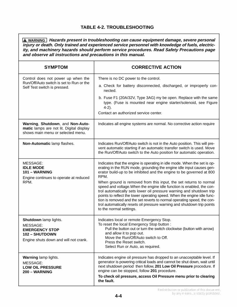
TABLE 4-2. TROUBLESHOOTING
Hazards present in troubleshooting can cause equipment damage, severe personalinjury or death. Only trained and experienced service personnel with knowledge of fuels, electric-ity, and machinery hazards should perform service procedures. Read Safety Precautions pageand observe all instructions and precautions in this manual.
WARNING
SYMPTOM CORRECTIVE ACTION
Control does not power up when theRun/Off/Auto switch is set to Run or theSelf Test switch is pressed.
There is no DC power to the control.
a. Check for battery disconnected, discharged, or improperly con-nected.
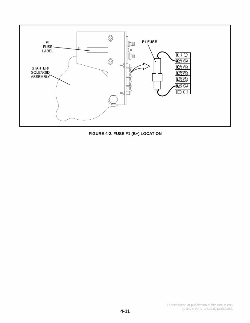
b. Fuse F1 (20A/32V, Type 3AG) my be open. Replace with the sametype. (Fuse is mounted near engine starter/solenoid, see Figure4-2).
Contact an authorized service center.
Warning , Shutdown , and Non-Auto-matic lamps are not lit. Digital displayshows main menu or selected menu.
Indicates all engine systems are normal. No corrective action require
Non-Automatic lamp flashes. Indicates Run/Off/Auto switch is not in the Auto position. This will pre-vent automatic starting if an automatic transfer switch is used. Movethe Run/Off/Auto switch to the Auto position for automatic operation.
MESSAGE:IDLE MODE101 – WARNINGEngine continues to operate at reducedRPM.
Indicates that the engine is operating in idle mode. When the set is op-erating in the RUN mode, grounding the engine idle input causes gen-erator build-up to be inhibited and the engine to be governed at 800RPM.When ground is removed from this input, the set returns to normalspeed and voltage.When the engine idle function is enabled, the con-trol automatically sets lower oil pressure warning and shutdown trippoints to reflect the lower operating speed. When the engine idle func-tion is removed and the set reverts to normal operating speed, the con-trol automatically resets oil pressure warning and shutdown trip pointsto the normal settings.
Shutdown lamp lights.MESSAGE:EMERGENCY STOP102 – SHUTDOWNEngine shuts down and will not crank.
Indicates local or remote Emergency Stop.To reset the local Emergency Stop button :
Pull the button out or turn the switch clockwise (button with arrow) and allow it to pop out.Move the Run/Off/Auto switch to Off. Press the Reset switch.Select Run or Auto, as required.
Warning lamp lights.MESSAGE:LOW OIL PRESSURE200 – WARNING
Indicates engine oil pressure has dropped to an unacceptable level. Ifgenerator is powering critical loads and cannot be shut down, wait untilnext shutdown period then follow, 201 Low Oil Pressure procedure. Ifengine can be stopped, follow 201 procedure.To check oil pressure, access Oil Pressure menu prior to clearingthe fault.

4-5
TABLE 4-2. TROUBLESHOOTING (CONT.)
Hazards present in troubleshooting can cause equipment damage, severe personalinjury or death. Only trained and experienced service personnel with knowledge of fuels, electric-ity, and machinery hazards should perform service procedures. Read Safety Precautions pageand observe all instructions and precautions in this manual.
WARNING
SYMPTOM CORRECTIVE ACTION
Shutdown lamp lights.MESSAGE:LOW OIL PRESSURE 201 – SHUTDOWN
Indicates engine oil pressure has dropped below the shutdown trippoint. Check oil level, lines and filters. If oil system is OK but oil level islow, replenish. Reset control and restart. Oil pressure limits are listedin Specifications. Contact an authorized service center.
Warning lamp lights.MESSAGE:OIL PRES SENDER204 – WARNING
Indicates that the engine oil pressure sender is not functioning correct-ly. Check that the engine oil pressure sender is properly connected.Contact an authorized service center.
Warning lamp lights.MESSAGE:LOW COOLANT TEMP210 – WARNINGSet is in standby mode but is not operat-ing. Warning occurs when engine cool-ant temperature is 70° F (21° C) or low-er. NOTE: In applications where theambient temperature falls below40°F (4°C), Low Engine Temp may beindicated even though the coolantheaters are operating.
Indicates engine coolant heater is not operating or is not circulatingcoolant. Check for the following conditions:
a. Coolant heater not connected to power supply. Check for blown fuseor disconnected heater cord and correct as required.
b. Check for low coolant level and replenish if required. Look for pos-sible coolant leakage points and repair as required.
c. Contact an authorized service center if none of the above.
Warning lamp lights.MESSAGE:HIGH COOLANT TEMP211 – WARNING
Indicates engine has begun to overheat and coolant temperature hasrisen to an unacceptable level: (215° F – standby / 207 ° F – primary) .If generator is powering non-critical and critical loads and cannot beshut down, use the following:
a. Reduce load if possible by turning off non-critical loads.
b. Check air inlets and outlets and remove any obstructions to airflow.If engine can be stopped, follow the next procedure.To check coolant temperature, access Coolant Temp menu priorto clearing the fault.
4-6
TABLE 4-2. TROUBLESHOOTING (CONT.)
Hazards present in troubleshooting can cause equipment damage, severe personalinjury or death. Only trained and experienced service personnel with knowledge of fuels, electric-ity, and machinery hazards should perform service procedures. Read Safety Precautions pageand observe all instructions and precautions in this manual.
WARNING
SYMPTOM CORRECTIVE ACTION
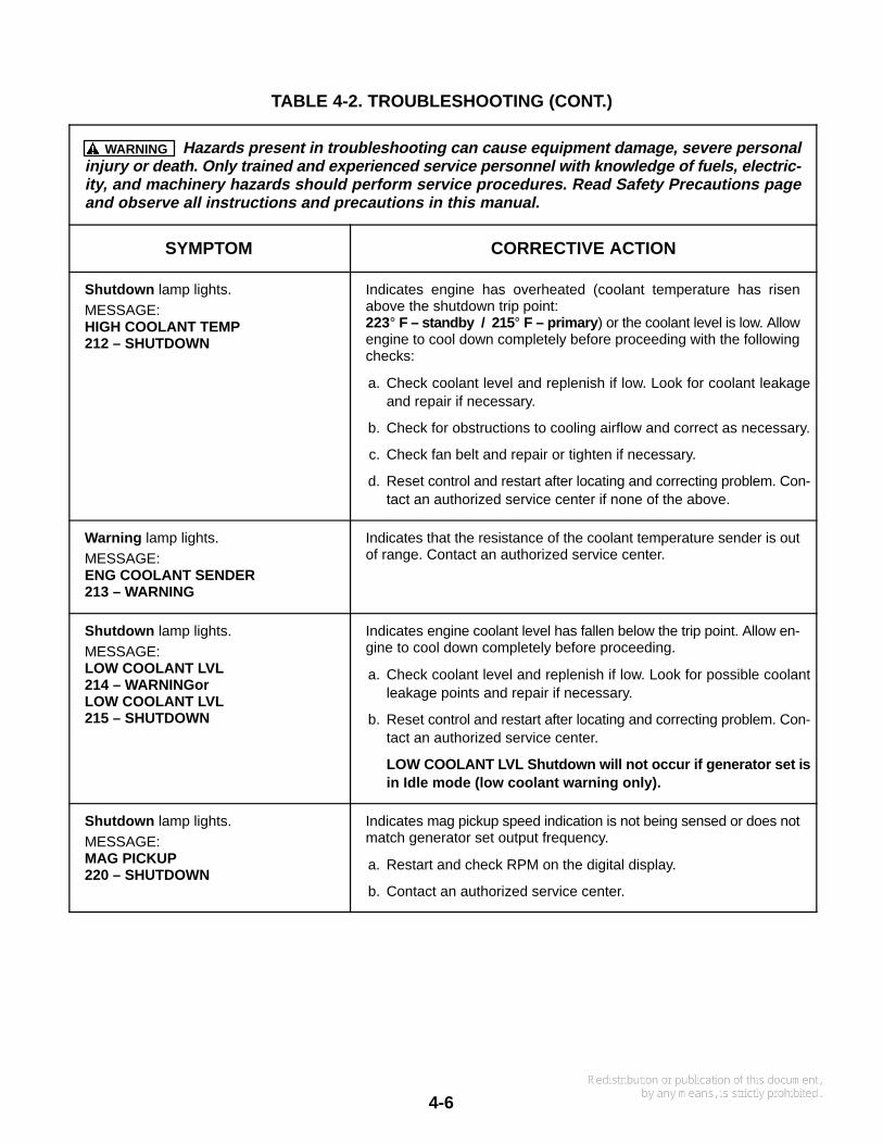
Shutdown lamp lights.MESSAGE:HIGH COOLANT TEMP212 – SHUTDOWN
Indicates engine has overheated (coolant temperature has risenabove the shutdown trip point:223° F – standby / 215 ° F – primary ) or the coolant level is low. Allowengine to cool down completely before proceeding with the followingchecks:
a. Check coolant level and replenish if low. Look for coolant leakageand repair if necessary.
b. Check for obstructions to cooling airflow and correct as necessary.
c. Check fan belt and repair or tighten if necessary.
d. Reset control and restart after locating and correcting problem. Con-tact an authorized service center if none of the above.
Warning lamp lights.MESSAGE:ENG COOLANT SENDER213 – WARNING
Indicates that the resistance of the coolant temperature sender is outof range. Contact an authorized service center.
Shutdown lamp lights.MESSAGE:LOW COOLANT LVL214 – WARNINGorLOW COOLANT LVL215 – SHUTDOWN
Indicates engine coolant level has fallen below the trip point. Allow en-gine to cool down completely before proceeding.
a. Check coolant level and replenish if low. Look for possible coolantleakage points and repair if necessary.
b. Reset control and restart after locating and correcting problem. Con-tact an authorized service center.
LOW COOLANT LVL Shutdown will not occur if generator set isin Idle mode (low coolant warning only).
Shutdown lamp lights.MESSAGE:MAG PICKUP220 – SHUTDOWN
Indicates mag pickup speed indication is not being sensed or does notmatch generator set output frequency.
a. Restart and check RPM on the digital display.
b. Contact an authorized service center.
4-7
TABLE 4-2. TROUBLESHOOTING (CONT.)
Hazards present in troubleshooting can cause equipment damage, severe personalinjury or death. Only trained and experienced service personnel with knowledge of fuels, electric-ity, and machinery hazards should perform service procedures. Read Safety Precautions pageand observe all instructions and precautions in this manual.
WARNING
SYMPTOM CORRECTIVE ACTION
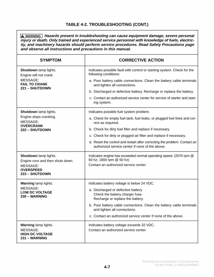
Shutdown lamp lights.Engine will not crank.MESSAGE:FAIL TO CRANK221 – SHUTDOWN
Indicates possible fault with control or starting system. Check for thefollowing conditions:
a. Poor battery cable connections. Clean the battery cable terminalsand tighten all connections.
b. Discharged or defective battery. Recharge or replace the battery.
c. Contact an authorized service center for service of starter and start-ing system.
Shutdown lamp lights.Engine stops cranking.MESSAGE:OVERCRANK222 – SHUTDOWN
Indicates possible fuel system problem.
a. Check for empty fuel tank, fuel leaks, or plugged fuel lines and cor-rect as required.
b. Check for dirty fuel filter and replace if necessary.
c. Check for dirty or plugged air filter and replace if necessary.
d. Reset the control and restart after correcting the problem. Contact anauthorized service center if none of the above.
Shutdown lamp lights.Engine runs and then shuts down.MESSAGE:OVERSPEED 223 – SHUTDOWN
Indicates engine has exceeded normal operating speed. (2070 rpm @60 hz; 1800 rpm @ 50 hz)Contact an authorized service center.
Warning lamp lights.MESSAGE:LOW DC VOLTAGE230 – WARNING
Indicates battery voltage is below 24 VDC.
a. Discharged or defective battery. Check the battery charger fuse. Recharge or replace the battery.
b. Poor battery cable connections. Clean the battery cable terminalsand tighten all connections.
c. Contact an authorized service center if none of the above.
Warning lamp lights.MESSAGE:HIGH DC VOLTAGE231 – WARNING
Indicates battery voltage exceeds 32 VDC.Contact an authorized service center.

4-8
TABLE 4-2. TROUBLESHOOTING (CONT.)
Hazards present in troubleshooting can cause equipment damage, severe personalinjury or death. Only trained and experienced service personnel with knowledge of fuels, electric-ity, and machinery hazards should perform service procedures. Read Safety Precautions pageand observe all instructions and precautions in this manual.
WARNING
SYMPTOM CORRECTIVE ACTION
Warning lamp lights.MESSAGE:WEAK BATTERY232 – WARNING
Indicates battery voltage drops below 60% of nominal for two seconds,during starting.Discharged or defective battery. See Warning message 230, LOW DC VOLTAGE .
Warning lamp lights.MESSAGE:LOW FUEL DAY240 – WARNING
Indicates day tank fuel supply is running low. Check fuel supply andreplenish as required.
Warning lamp lights.MESSAGE:LOW FUEL241 – WARNING
Indicates fuel supply is running low. Check fuel supply and replenishas required.
Shutdown lamp lights.MESSAGE:EEPROM ERROR250 – SHUTDOWN
Indicates PCC memory error. Data corruption of critical operating pa-rameters. Contact an authorized service center.
Warning lamp lights.MESSAGE:EEPROM ERROR251 – WARNING or252 – WARNING
Indicates PCC memory error. Data corruption of noncritical operatingparameters. Contact an authorized service center.
Shutdown lamp lights.MESSAGE:CUSTOMER FAULT 1260 – SHUTDOWNorGROUND FAULT261 – SHUTDOWNorDAY TANK262 – SHUTDOWNorHIGH GEN TEMP263 – SHUTDOWN
When any one of these customer defined inputs is closed to ground,the corresponding fault message is displayed. The nature of the fault isan optional customer selection. These fault functions can be pro-grammed to initiate a shutdown or a warning.As indicated by the Shutdown lamp, a shutdown response has beenpreselected.Contact an authorized service center.Note: Customer fault messages are editable. The message displayedfor the code shown (260 thru 263) may have been edited and may notappear as shown in this table.
4-9
TABLE 4-2. TROUBLESHOOTING (CONT.)
Hazards present in troubleshooting can cause equipment damage, severe personalinjury or death. Only trained and experienced service personnel with knowledge of fuels, electric-ity, and machinery hazards should perform service procedures. Read Safety Precautions pageand observe all instructions and precautions in this manual.
WARNING
SYMPTOM CORRECTIVE ACTION
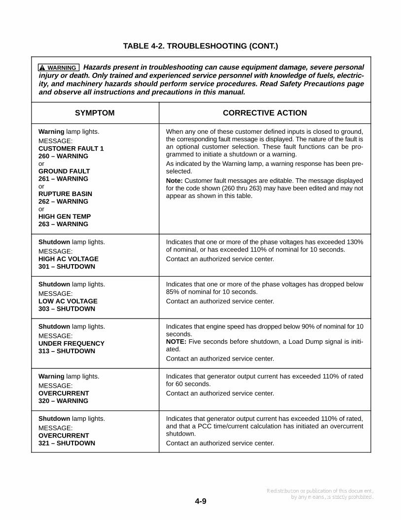
Warning lamp lights.MESSAGE:CUSTOMER FAULT 1260 – WARNINGorGROUND FAULT261 – WARNINGorRUPTURE BASIN262 – WARNINGorHIGH GEN TEMP263 – WARNING
When any one of these customer defined inputs is closed to ground,the corresponding fault message is displayed. The nature of the fault isan optional customer selection. These fault functions can be pro-grammed to initiate a shutdown or a warning.As indicated by the Warning lamp, a warning response has been pre-selected.Note: Customer fault messages are editable. The message displayedfor the code shown (260 thru 263) may have been edited and may notappear as shown in this table.
Shutdown lamp lights.MESSAGE:HIGH AC VOLTAGE301 – SHUTDOWN
Indicates that one or more of the phase voltages has exceeded 130%of nominal, or has exceeded 110% of nominal for 10 seconds.Contact an authorized service center.
Shutdown lamp lights.MESSAGE:LOW AC VOLTAGE303 – SHUTDOWN
Indicates that one or more of the phase voltages has dropped below85% of nominal for 10 seconds.Contact an authorized service center.
Shutdown lamp lights.MESSAGE:UNDER FREQUENCY313 – SHUTDOWN
Indicates that engine speed has dropped below 90% of nominal for 10seconds.NOTE: Five seconds before shutdown, a Load Dump signal is initi-ated.Contact an authorized service center.
Warning lamp lights.MESSAGE:OVERCURRENT320 – WARNING
Indicates that generator output current has exceeded 110% of ratedfor 60 seconds.Contact an authorized service center.
Shutdown lamp lights.MESSAGE:OVERCURRENT321 – SHUTDOWN
Indicates that generator output current has exceeded 110% of rated,and that a PCC time/current calculation has initiated an overcurrentshutdown.Contact an authorized service center.

4-10
TABLE 4-2. TROUBLESHOOTING (CONT.)
Hazards present in troubleshooting can cause equipment damage, severe personalinjury or death. Only trained and experienced service personnel with knowledge of fuels, electric-ity, and machinery hazards should perform service procedures. Read Safety Precautions pageand observe all instructions and precautions in this manual.
WARNING
SYMPTOM CORRECTIVE ACTION
Shutdown lamp lights.MESSAGE:SHORT CIRCUIT322 – SHUTDOWN
Indicates that generator output current has exceeded 175% of rated.Contact an authorized service center.
Warning lamp lights.MESSAGE:OVERLOAD330 – WARNING
Indicates that three-phase power output exceeds 105% of standby (or115% of prime) rating. After five seconds, the Load Dump output is ac-tivated. After 60 seconds, the OVERLOAD warning is activated.Contact an authorized service center.
Shutdown lamp lights.MESSAGE:REVERSE POWER335 – SHUTDOWN
Indicates improper CT or PT phasing. (Non-parallel units only.)Contact an authorized service center.
Engine starts from generator controlpanel but will not start automatically orfrom a remote panel. (Note: The Run/Off/Auto switch must be in the Auto posi-tion for automatic or remote starting).
Check the control wiring between the remote switch and the PCC.Contact an authorized service center.
No AC output voltage. Contact an authorized service center.
4-11
STARTER/SOLENOIDASSEMBLY
F1FUSELABEL
F1 FUSE
FIGURE 4-2. FUSE F1 (B+) LOCATION

4-12
THIS PAGE LEFT INTENTIONALLY BLANK
5-1
5. Operation (Detector Control)
GENERAL
This section covers prestart checks, starting andstopping and operating the generator set. Each op-erator should read through this entire section beforeattempting to start the set. It is essential that the op-erator be completely familiar with the set for safeoperation. Refer to Section 8 for operating recom-mendations.
PRESTART CHECKS
Before starting, be sure the following checks havebeen made and the unit is ready for operation. Referto the Maintenance section for the recommendedprocedures.
Lubrication
Check the engine oil level. Keep the oil level near aspossible to the dipstick high mark without overfilling.
Coolant
Check the engine coolant level. Refer to “CoolingSystems” in the Maintenance section of this manu-als for proper procedure.
Fuel
Make sure the fuel tanks have sufficient fuel andthat fuel system is primed. Check to make surethere are no leaks and that all fittings are tight.
Exhaust
Check to make sure entire exhaust system is tight,that no combustible materials are near system, andgases are discharged away from building openings.
CONTROL PANEL
The following describes the function and operationof the Detector Control panel. All instruments andcontrol switches are located on the face of the con-trol panel as illustrated in Figures 5-1 through 5-3.The control panel is separated into a DC panel formonitoring the engine and an AC panel for monitor-ing the generator.
5-2
PANEL LAMP
RUN/STOP/REMOTESWITCH
RESET/LAMPTEST/ PANEL
LAMP SWITCH
INDICATORLAMPS
RUNNINGTIME METER
EMERGENCY STOPPUSHBUTTON
DC VOLTMETER
COOLANTTEMPERATURE
GAUGE
OIL PRESSUREGAUGE
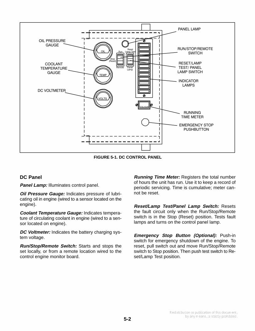
FIGURE 5-1. DC CONTROL PANEL
DC Panel
Panel Lamp: Illuminates control panel.
Oil Pressure Gauge: Indicates pressure of lubri-cating oil in engine (wired to a sensor located on theengine).
Coolant Temperature Gauge: Indicates tempera-ture of circulating coolant in engine (wired to a sen-sor located on engine).
DC Voltmeter: Indicates the battery charging sys-tem voltage.
Run/Stop/Remote Switch: Starts and stops theset locally, or from a remote location wired to thecontrol engine monitor board.
Running Time Meter: Registers the total numberof hours the unit has run. Use it to keep a record ofperiodic servicing. Time is cumulative; meter can-not be reset.
Reset/Lamp Test/Panel Lamp Switch: Resetsthe fault circuit only when the Run/Stop/Remoteswitch is in the Stop (Reset) position. Tests faultlamps and turns on the control panel lamp.
Emergency Stop Button (Optional): Push-inswitch for emergency shutdown of the engine. Toreset, pull switch out and move Run/Stop/Remoteswitch to Stop position. Then push test switch to Re-set/Lamp Test position.

5-3
Indicator Lamps: The control panel has twelve in-dicator lamps which are described as follows:
• RUN (green) lamp comes on when starter cir-cuit opens after set starting.
• PRE LO OIL PRES (yellow) indicates engineoil pressure is marginally low.
• PRE HI ENG TEMP (yellow) indicates enginetemperature is marginally high.
• LO OIL PRES (red) indicates engine has shutdown because of critically low oil pressure.
• HI ENG TEMP (red) indicates engine has shutdown because of critically high engine temper-ature.
• OVERSPEED (red) indicates engine has shutdown because of excessive speed.
• OVERCRANK (red) indicates engine has failedto start during the cranking period.
• FAULT 1 (red) lamp indicates an undedicatedfault. May be field programmed as a shutdownor non-shutdown, and as a timed or non-timedfault. (Normally set for timed shutdown),
ORBASIN (yellow) lamp (optional) indicates innerfuel tank leaking to outer basin. (Normally setfor warning while running or during standby.)
• FAULT 2 (red) lamp indicates same features asFault 1 (normally set for non-timed shutdown).
• LOW ENG TEMP (yellow) lamp lights if enginetemperature is marginally low for starting. Itmay indicate an inoperative coolant heater.
• LO FUEL (yellow) indicates fuel is marginallylow.
• SWITCH OFF (flashing red) indicates genera-tor set is not in automatic start mode.
FIGURE 5-2. INDICATOR LAMPS
5-4
UPPER AND LOWERSCALE INDICATOR
VOLTAGEADJUST
EXCITATIONFIELD BREAKER
PHASESELECTOR
SWITCH
FREQUENCY/RPM METER
AC AMMETER
AC VOLTMETER
A-C AMPERES
A-C VOLTS
HERTZ
RPM
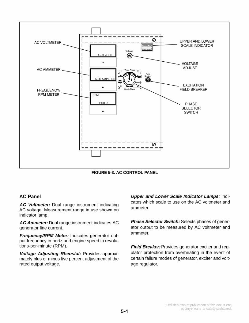
FIGURE 5-3. AC CONTROL PANEL
AC Panel
AC Voltmeter: Dual range instrument indicatingAC voltage. Measurement range in use shown onindicator lamp.
AC Ammeter: Dual range instrument indicates ACgenerator line current.
Frequency/RPM Meter: Indicates generator out-put frequency in hertz and engine speed in revolu-tions-per-minute (RPM).
Voltage Adjusting Rheostat: Provides approxi-mately plus or minus five percent adjustment of therated output voltage.
Upper and Lower Scale Indicator Lamps: Indi-cates which scale to use on the AC voltmeter andammeter.
Phase Selector Switch: Selects phases of gener-ator output to be measured by AC voltmeter andammeter.
Field Breaker: Provides generator exciter and reg-ulator protection from overheating in the event ofcertain failure modes of generator, exciter and volt-age regulator.
5-5
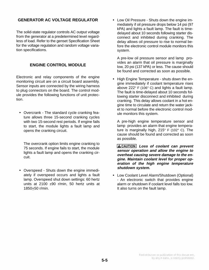
GENERATOR AC VOLTAGE REGULATOR
The solid-state regulator controls AC output voltagefrom the generator at a predetermined level regard-less of load. Refer to the genset Specification Sheetfor the voltage regulation and random voltage varia-tion specifications.
ENGINE CONTROL MODULE
Electronic and relay components of the enginemonitoring circuit are on a circuit board assembly.Sensor inputs are connected by the wiring harnessto plug connectors on the board. The control mod-ule provides the following functions of unit protec-tion.
• Overcrank - The standard cycle cranking fea-ture allows three 15-second cranking cycleswith two 15-second rest periods. If engine failsto start, the module lights a fault lamp andopens the cranking circuit.
The overcrank option limits engine cranking to75 seconds. If engine fails to start, the modulelights a fault lamp and opens the cranking cir-cuit.
• Overspeed - Shuts down the engine immedi-ately if overspeed occurs and lights a faultlamp. Overspeed shut down settings: 60 hertzunits at 2100 ±90 r/min, 50 hertz units at1850+50 r/min.
• Low Oil Pressure - Shuts down the engine im-mediately if oil pressure drops below 14 psi (97kPA) and lights a fault lamp. The fault is time-delayed about 10 seconds following starter dis-connect and inhibited during cranking. Thedelay allows oil pressure to rise to normal be-fore the electronic control module monitors thissystem.
A pre-low oil pressure sensor and lamp pro-vides an alarm that oil pressure is marginallylow, 20 psi (137 kPA) or less. The cause shouldbe found and corrected as soon as possible.
• High Engine Temperature - shuts down the en-gine immediately if coolant temperature risesabove 222° F (106° C) and lights a fault lamp.The fault is time-delayed about 10 seconds fol-lowing starter disconnect and inhibited duringcranking. This delay allows coolant in a hot en-gine time to circulate and return the water jack-et to normal before the electronic control mod-ule monitors this system.
A pre-high engine temperature sensor andlamp provides an alarm that engine tempera-ture is marginally high, 215° F (102° C). Thecause should be found and corrected as soonas possible.
CAUTION Loss of coolant can preventsensor operation and allow the engine tooverheat causing severe damage to the en-gine. Maintain coolant level for proper op-eration of the high engine temperatureshutdown system.
• Low Coolant Level Alarm/Shutdown (Optional)- An electronic switch that provides enginealarm or shutdown if coolant level falls too low.It also turns on the fault lamp.
5-6
STARTING
The following sections cover the three systemsused to start the generator set.
Before starting the generator set, make sure thatexhaust and fuel fittings are tight and properly posi-tioned and that proper maintenance has been per-formed. See Prestart Checks in this section.
Starting at Control Panel
Move the Run-Stop-Remote switch on the DC pan-el to the RUN position. This will activate the enginecontrol system and the starting system. The starterwill begin cranking and after a few seconds the en-gine should start. The starter will disconnect auto-matically.
If the engine does not start, the starter will disen-gage after a specified period of time and the controlwill indicate an overcrank fault. Generator sets withthe optional overcrank control will crank continu-ously for up to 75 seconds before disengaging thestarter. Generator sets with the standard cyclecranking feature will crank for 15 seconds in eachcycle until 3 cycles have been completed. To clearan overcrank fault, place the Run-Stop-Remoteswitch in the STOP position and momentarily pressthe Reset switch. Wait two minutes for the startermotor to cool and then repeat the starting proce-dure. If the engine does not run after a second at-tempt at starting, refer to the Troubleshooting sec-tion.
Starting From Remote Location
Move the Run/Stop/Remote switch on the genera-tor set DC panel to the REMOTE position. This al-lows the generator set to be started from a remoteswitch. Closing the remote switch initiates the start-ing sequence described in the previous section.
Automatic Starting
Place the Run/Stop/Remote switch on the genera-tor set DC panel in the REMOTE position if an auto-matic transfer switch is used. This allows the trans-fer switch to start the generator set if a power outageoccurs and stop it when the power returns.
Cold Starting With Loads
In accordance with NFPA 110, Cummins PowerGeneration recommends installing standby gener-
ator sets (life safety systems) equipped with coolantheaters in locations where the minimum ambienttemperature is above 40°F (4°C). NFPA also re-quires that the engine coolant be maintained at aminimum of 90°F (32°C) and for most applications,accept the emergency load in 10 seconds or less.Although most generator sets will start in tempera-tures below 40°F (4°C) when equipped with coolantheaters, it might take some running time to warmthe engine up before a load can be applied whenambient temperatures are below 40°F (4°C).
The Low Engine Temperature (LET) lamp on theDetector control is provided to meet the require-ments of NFPA 110. The LET sensor signals analarm when the engine coolant temperature fallsbelow 70°F (21°C). In applications where the ambi-ent temperature falls below 40°F (4°C), the LETmay be lit even though the coolant heaters are con-nected and operable. Under these conditions, al-though the generator set may start, it may not beable to accept load within 10 seconds. When thiscondition occurs, check the coolant heaters forproper operation. If the coolant heaters are operat-ing properly, other precautions might be necessaryto warm the engine before applying a load.
STOPPING
Before Stopping
Run the generator set at no load for three to fiveminutes before stopping. This allows the lubricatingoil and engine coolant to carry heat away from thecombustion chamber and bearings.
To Stop
If the set was started at the set control panel or at aremote control panel, move the Run/Stop/Remoteswitch or remote starting switch to the STOP posi-tion. If the set was started by an automatic transferswitch, the transfer switch will send a remote (timeddelay) stop signal after the normal power source re-turns.
Emergency Stop
An optional emergency stop button is located on theright side of control panel (Figure 5-1). Push buttonin for emergency stop. To reset, pull switch out andmove Run/Stop/Remote switch to Stop position.Then push test switch to Reset/Lamp Test position.
6-1
6. Troubleshooting (Detector Control)
The generator set has sensors that continuouslymonitor the engine for abnormal conditions, such aslow oil pressure or high coolant temperature. Ifthese conditions occur, the engine monitor acti-vates a fault lamp, and may also stop the engine(depending on the condition). If the generator set isstopped for this reason, the operator may be able torestart the set after making adjustments or correc-tions. This section describes the fault condition sys-tem, and suggests troubleshooting procedures.
The control has a single green light to indicate RUN,four amber lights and seven red fault lights. Thecontrol also has a terminal connection for an audi-ble alarm, which sounds when a fault occurs.
SAFETY CONSIDERATIONS
WARNING Contacting high voltage compo-nents can cause electrocution, resulting in se-vere personal injury or death. Keep control andoutput box covers in place during troubleshoot-ing.
High voltages are present inside the control box andgenerator output box when the set is running. Donot open the control box or generator output boxwhile the set is running.
WARNING Ignition of explosive battery gasescan cause severe personal injury or death. Arc-ing at battery terminals, light switch or otherequipment, flame, pilot lights and sparks can ig-nite battery gas. Do not smoke, or switchtrouble light ON or OFF near battery. Dischargestatic electricity from body before touching bat-teries by first touching a grounded metal sur-face.
Ventilate battery area before working on or nearbattery—Wear goggles—Stop genset and dis-connect charger before disconnecting batterycables—Disconnect negative (–) cable first andreconnect last.
CAUTION Disconnect battery charger from ACsource before disconnecting battery cables.Otherwise, disconnecting cables can result involtage spikes damaging to DC control circuitsof the set.
WARNING Accidental starting of the generatorset can cause severe personal injury or death.Prevent accidental starting by disconnectingthe negative (–) cable from the battery terminal.
When troubleshooting a set that is shut down, makecertain the generator set cannot be accidentally re-started as follows:
4. Move the Run/Stop/Remote switch on the con-trol panel to the Stop position.
5. Turn off or remove AC power from the batterycharger.
6. Remove the negative (–) battery cable from thegenerator set starting battery.
When a fault lamp turns on during operation, followthe procedures listed in Table 6-1 to locate and cor-rect the problem. For any symptom not listed, con-tact an authorized service center for assistance.
RESETTING THE CONTROL
The external alarm and fault lamp may be deacti-vated by moving the Run/Stop/Remote switch tothe Stop position and pressing the Reset/LampTest/Panel Lamp switch. Locate the problem andcorrect it before restarting the set. While pressingthe Reset/Lamp Test/Panel Lamp switch, make cer-tain that all lamps light.
LINE CIRCUIT BREAKER (OPTIONAL)
The optional line circuit breaker mounts on the gen-erator output box. If the load exceeds the generatorcurrent rating, the line circuit breaker will open, pre-venting the generator from being overloaded. If thecircuit breaker trips, locate the source of the over-load and correct as necessary. Manually reset thebreaker to reconnect the load to the generator.
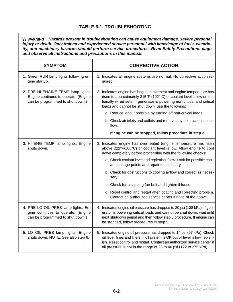
6-2
TABLE 6-1. TROUBLESHOOTING
Hazards present in troubleshooting can cause equipment damage, severe personalinjury or death. Only trained and experienced service personnel with knowledge of fuels, electric-ity, and machinery hazards should perform service procedures. Read Safety Precautions pageand observe all instructions and precautions in this manual.
WARNING
SYMPTOM CORRECTIVE ACTION
1. Green RUN lamp lights following en-gine startup.
1. Indicates all engine systems are normal. No corrective action re-quired.
2. PRE HI ENGINE TEMP lamp lights.Engine continues to operate. (Enginecan be programmed to shut down.)
2. Indicates engine has begun to overheat and engine temperature hasrisen to approximately 215°F (102° C) or coolant level is low on op-tionally wired sets. If generator is powering non-critical and criticalloads and cannot be shut down, use the following:
a. Reduce load if possible by turning off non-critical loads.
b. Check air inlets and outlets and remove any obstructions to air-flow.
If engine can be stopped, follow procedure in step 3.
3. HI ENG TEMP lamp lights. Engineshuts down.
3. Indicates engine has overheated (engine temperature has risenabove 222°F/106°C) or coolant level is low. Allow engine to cooldown completely before proceeding with the following checks:
a. Check coolant level and replenish if low. Look for possible cool-ant leakage points and repair if necessary.
b. Check for obstructions to cooling airflow and correct as neces-sary.
c. Check for a slipping fan belt and tighten if loose.
d. Reset control and restart after locating and correcting problem.Contact an authorized service center if none of the above.
4. PRE LO OIL PRES lamp lights. En-gine continues to operate. (Enginecan be programmed to shut down.)
4. Indicates engine oil pressure has dropped to 20 psi (138 kPa). If gen-erator is powering critical loads and cannot be shut down, wait untilnext shutdown period and then follow step 5 procedure. If engine canbe stopped, follow procedures in step 5.
5. LO OIL PRES lamp lights. Engineshuts down. NOTE: See also step 6.
5. Indicates engine oil pressure has dropped to 14 psi (97 kPa). Checkoil level, lines and filters. If oil system is OK but oil level is low, replen-ish. Reset control and restart. Contact an authorized service center ifoil pressure is not in the range of 25 to 40 psi (172 to 275 kPa).
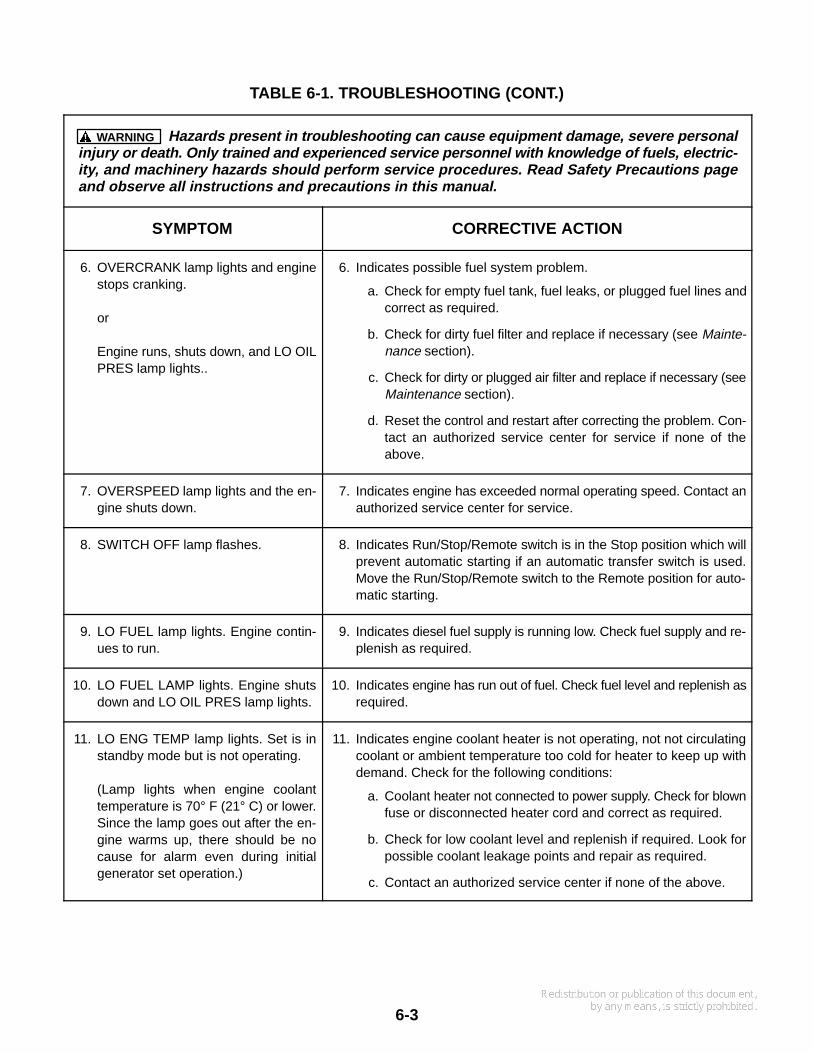
6-3
TABLE 6-1. TROUBLESHOOTING (CONT.)
Hazards present in troubleshooting can cause equipment damage, severe personalinjury or death. Only trained and experienced service personnel with knowledge of fuels, electric-ity, and machinery hazards should perform service procedures. Read Safety Precautions pageand observe all instructions and precautions in this manual.
WARNING
SYMPTOM CORRECTIVE ACTION
6. OVERCRANK lamp lights and enginestops cranking.
or
Engine runs, shuts down, and LO OILPRES lamp lights..
6. Indicates possible fuel system problem.
a. Check for empty fuel tank, fuel leaks, or plugged fuel lines andcorrect as required.
b. Check for dirty fuel filter and replace if necessary (see Mainte-nance section).
c. Check for dirty or plugged air filter and replace if necessary (seeMaintenance section).
d. Reset the control and restart after correcting the problem. Con-tact an authorized service center for service if none of theabove.
7. OVERSPEED lamp lights and the en-gine shuts down.
7. Indicates engine has exceeded normal operating speed. Contact anauthorized service center for service.
8. SWITCH OFF lamp flashes. 8. Indicates Run/Stop/Remote switch is in the Stop position which willprevent automatic starting if an automatic transfer switch is used.Move the Run/Stop/Remote switch to the Remote position for auto-matic starting.
9. LO FUEL lamp lights. Engine contin-ues to run.
9. Indicates diesel fuel supply is running low. Check fuel supply and re-plenish as required.
10. LO FUEL LAMP lights. Engine shutsdown and LO OIL PRES lamp lights.
10. Indicates engine has run out of fuel. Check fuel level and replenish asrequired.
11. LO ENG TEMP lamp lights. Set is instandby mode but is not operating.
(Lamp lights when engine coolanttemperature is 70° F (21° C) or lower.Since the lamp goes out after the en-gine warms up, there should be nocause for alarm even during initialgenerator set operation.)
11. Indicates engine coolant heater is not operating, not not circulatingcoolant or ambient temperature too cold for heater to keep up withdemand. Check for the following conditions:
a. Coolant heater not connected to power supply. Check for blownfuse or disconnected heater cord and correct as required.
b. Check for low coolant level and replenish if required. Look forpossible coolant leakage points and repair as required.
c. Contact an authorized service center if none of the above.
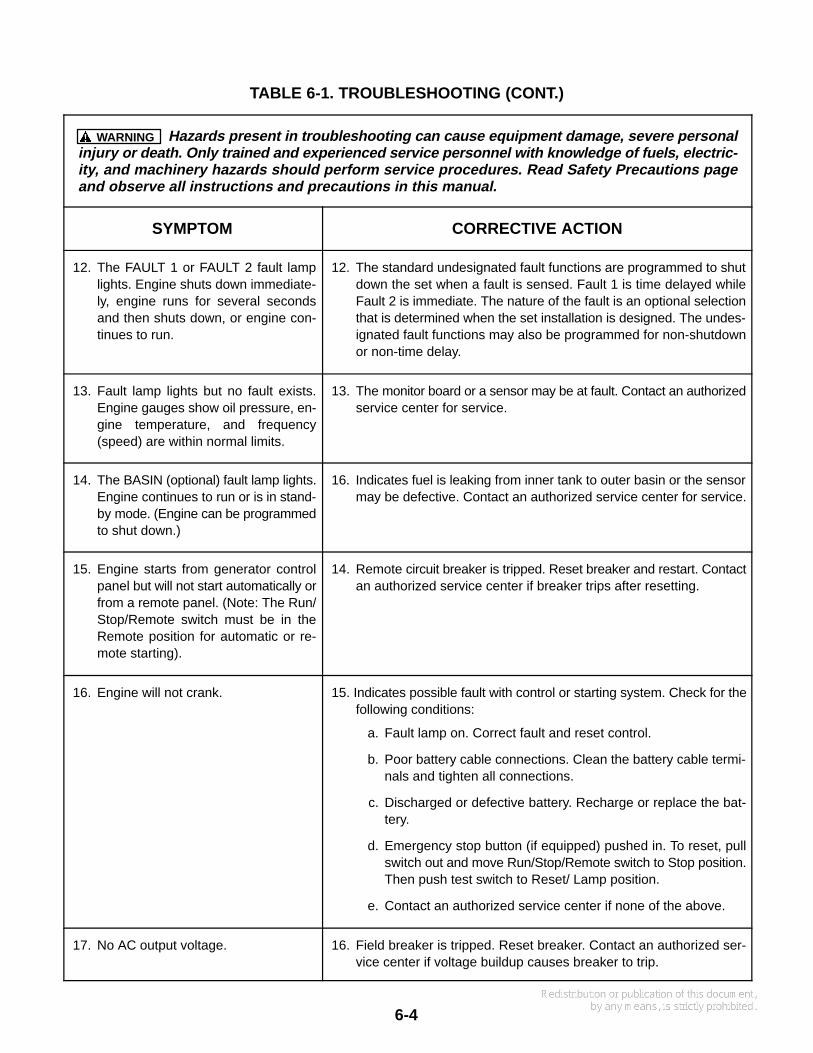
6-4
TABLE 6-1. TROUBLESHOOTING (CONT.)
Hazards present in troubleshooting can cause equipment damage, severe personalinjury or death. Only trained and experienced service personnel with knowledge of fuels, electric-ity, and machinery hazards should perform service procedures. Read Safety Precautions pageand observe all instructions and precautions in this manual.
WARNING
SYMPTOM CORRECTIVE ACTION
12. The FAULT 1 or FAULT 2 fault lamplights. Engine shuts down immediate-ly, engine runs for several secondsand then shuts down, or engine con-tinues to run.
12. The standard undesignated fault functions are programmed to shutdown the set when a fault is sensed. Fault 1 is time delayed whileFault 2 is immediate. The nature of the fault is an optional selectionthat is determined when the set installation is designed. The undes-ignated fault functions may also be programmed for non-shutdownor non-time delay.
13. Fault lamp lights but no fault exists.Engine gauges show oil pressure, en-gine temperature, and frequency(speed) are within normal limits.
13. The monitor board or a sensor may be at fault. Contact an authorizedservice center for service.
14. The BASIN (optional) fault lamp lights.Engine continues to run or is in stand-by mode. (Engine can be programmedto shut down.)
16. Indicates fuel is leaking from inner tank to outer basin or the sensormay be defective. Contact an authorized service center for service.
15. Engine starts from generator controlpanel but will not start automatically orfrom a remote panel. (Note: The Run/Stop/Remote switch must be in theRemote position for automatic or re-mote starting).
14. Remote circuit breaker is tripped. Reset breaker and restart. Contactan authorized service center if breaker trips after resetting.
16. Engine will not crank. 15. Indicates possible fault with control or starting system. Check for thefollowing conditions:
a. Fault lamp on. Correct fault and reset control.
b. Poor battery cable connections. Clean the battery cable termi-nals and tighten all connections.
c. Discharged or defective battery. Recharge or replace the bat-tery.
d. Emergency stop button (if equipped) pushed in. To reset, pullswitch out and move Run/Stop/Remote switch to Stop position.Then push test switch to Reset/ Lamp position.
e. Contact an authorized service center if none of the above.
17. No AC output voltage. 16. Field breaker is tripped. Reset breaker. Contact an authorized ser-vice center if voltage buildup causes breaker to trip.
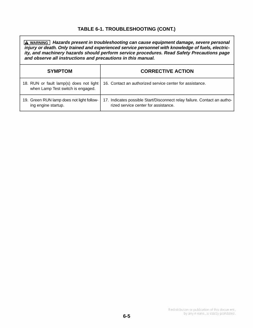
6-5
TABLE 6-1. TROUBLESHOOTING (CONT.)
Hazards present in troubleshooting can cause equipment damage, severe personalinjury or death. Only trained and experienced service personnel with knowledge of fuels, electric-ity, and machinery hazards should perform service procedures. Read Safety Precautions pageand observe all instructions and precautions in this manual.
WARNING
SYMPTOM CORRECTIVE ACTION
18. RUN or fault lamp(s) does not lightwhen Lamp Test switch is engaged.
16. Contact an authorized service center for assistance.
19. Green RUN lamp does not light follow-ing engine startup.
17. Indicates possible Start/Disconnect relay failure. Contact an autho-rized service center for assistance.

6-6
THIS PAGE LEFT INTENTIONALLY BLANK
7-1
7. Maintenance
Establish and adhere to a definite schedule formaintenance and service based on the applicationand severity of the environment. Table 7-1 coversthe recommended service intervals for a generatorset on STANDBY service. If the set will be subjectedto extreme operating conditions, the service inter-vals should be reduced accordingly. Some of thefactors that can affect the maintenance scheduleare the following:
• Use for continuous duty (prime power)• Extremes in ambient temperature• Exposure to weather• Exposure to salt water
• Exposure to dust, sand or other airborne contaminates.
Consult with your local Cummins Power Generationdistributor if the generator set will be subjected toany extreme operating conditions and determine asuitable schedule of maintenance. Use the runningtime meter to keep an accurate log of all service per-formed for warranty support. Perform all service atthe time period indicated or after the number of op-erating hours indicated, whichever comes first. UseTable 7-1 to determine the maintenance requiredand then refer to the sections that follow for the cor-rect service procedures.
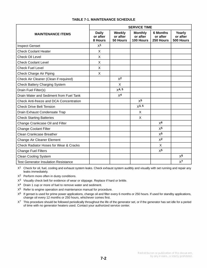
7-2
TABLE 7-1. MAINTENANCE SCHEDULE
SERVICE TIME
MAINTENANCE ITEMS Dailyor after8 Hours
Weeklyor after
50 Hours
Monthlyor after
100 Hours
6 Monthsor after
250 Hours
Yearlyor after
500 Hours
Inspect Genset X1
Check Coolant Heater X
Check Oil Level X
Check Coolant Level X
Check Fuel Level X
Check Charge Air Piping X
Check Air Cleaner (Clean if required) X2
Check Battery Charging System X
Drain Fuel Filter(s) X4, 5
Drain Water and Sediment from Fuel Tank X4
Check Anti-freeze and DCA Concentration X5
Check Drive Belt Tension X3, 5
Drain Exhaust Condensate Trap X
Check Starting Batteries X
Change Crankcase Oil and Filter X6
Change Coolant Filter X5
Clean Crankcase Breather X5
Change Air Cleaner Element X2
Check Radiator Hoses for Wear & Cracks X
Change Fuel Filters X5
Clean Cooling System X5
Test Generator Insulation Resistance X7
X1 Check for oil, fuel, cooling and exhaust system leaks. Check exhaust system audibly and visually with set running and repair anyleaks immediately.
X2 Perform more often in dusty conditions.
X3 Visually check belt for evidence of wear or slippage. Replace if hard or brittle.
X4 Drain 1 cup or more of fuel to remove water and sediment.
X5 Refer to engine operation and maintenance manual for procedure.
X6 If genset is used for prime power applications, change oil and filter every 6 months or 250 hours. If used for standby applications,change oil every 12 months or 250 hours, whichever comes first.
X7 This procedure should be followed periodically throughout the life of the generator set, or if the generator has set idle for a periodof time with no generator heaters used. Contact your authorized service center.

7-3
GENERATOR SET INSPECTION
During operation, be alert for mechanical problemsthat could create unsafe or hazardous conditions.The following sections cover several areas thatshould be frequently inspected for continued safeoperation.
Exhaust SystemWith the generator set operating, inspect the entireexhaust system visually and audibly including theexhaust manifold, muffler and exhaust pipe. Checkfor leaks at all connections, welds, gaskets andjoints and also make sure that exhaust pipes are notheating surrounding areas excessively. If any leaksare detected, shut down the genset and have leakscorrected immediately.
WARNING Inhalation of exhaust gases can re-sult in severe personal injury or death. Be suredeadly exhaust gas is piped outside and awayfrom any windows, doors, vents or other inletsto building and not allowed to accumulate in in-habitable areas.
Fuel SystemWith the generator set operating, inspect the fuelsupply lines, return lines, filters and fittings forcracks and abrasions and make sure they are notrubbing against anything that could cause break-age. If any leaks are detected, have them correctedimmediately.
WARNING Ignition of fuel can cause severepersonal injury or death by fire or explosion. Donot permit any flame, cigarette, arcing switch orequipment, pilot light, or other igniter near thefuel system or in areas sharing ventilation.
AC Electric SystemCheck the following while the genset is operating;otherwise measure load lines L1, L2 and L3 usingthe appropriate AC meter.
Frequency/RPM Meter: The generator frequencyshould be stable and the reading should be thesame as the genset nameplate rating (50 or 60hz/1500 or 1800 RPM).
AC Voltmeter: Turn the phase selector switch toeach line-to-line phase selection shown on the voltsscale (L1-L2, L2-L3 and L3-L1). Read the AC volt-meter using the upper or lower scale as indicated bythe scale indicator lamp. At no load, the line-to-linevoltage(s) should be the same as the genset name-plate rating.
AC Ammeter: Turn the phase selector switch toeach phase selection shown on the amps scale (L1,L2 and L3). Read the ammeter using the upper orlower scale as indicated by the scale indicator lamp.At no load the current ratings should be zero. With aload applied, each line current should be about thesame.
Fault Lamps (Detector Only): Push the Reset/Lamp switch on the control panel. All indicatorlamps should light. Verify that all the bulbs are onand then release the switch. Replace any bulbs thatare burned out.
DC Electrical SystemCheck the terminals on the batteries for clean andtight connections. Loose or corroded connectionscreate resistance which can hinder starting. Referto BATTERIES later in this section for cleaning andsafety precautions.
Engine
Monitor fluid levels and oil pressure and coolanttemperatures frequently. Most engine problemsgive an early warning. Look and listen for changesin engine performance, sound, or appearance thatcan indicate service or repair is needed. Some en-gine changes to look for are as follows:
• Misfire• Vibration• Unusual noises• Sudden changes in engine operating tempera-
tures or pressures• Excessive exhaust smoke• Loss of power• An increase in oil consumption• An increase in fuel consumption• Fuel, oil, or coolant leaks.
7-4
GENERATOR SET MAINTENANCE(Battery Disconnected)
WARNING Ignition of explosive battery gasescan cause severe personal injury or death. Arc-ing at battery terminals, light switch or otherequipment, flame, pilot lights and sparks can ig-nite battery gas. Do not smoke, or switchtrouble light ON or OFF near battery. Dischargestatic electricity from body before touching bat-teries by first touching a grounded metal sur-face.
Ventilate battery area before working on or nearbattery—Wear goggles—Stop genset and dis-connect charger before disconnecting batterycables—Disconnect negative (–) cable first andreconnect last.
CAUTION Disconnect battery charger from ACsource before disconnecting battery cables.Otherwise, disconnecting cables can result involtage spikes damaging to DC control circuitsof the set.
WARNING Accidental starting of the generatorset can cause severe personal injury or death.Prevent accidental starting by disconnectingthe negative (–) cable from the battery terminalbefore beginning maintenance procedures.
When performing the following maintenance proce-dures, make certain the generator set cannot be ac-cidentally restarted as follows:
7. Place the run switch on the control panel to theOFF or STOP position.
8. Turn off or remove AC power from the batterycharger.
9. Remove the negative (–) battery cable from thegenerator set starting battery.
Mechanical InspectionWith the generator set stopped, check for loosebelts and fittings, leaking gaskets and hoses, or anysigns of mechanical damage. If any problems arefound, have them corrected immediately.
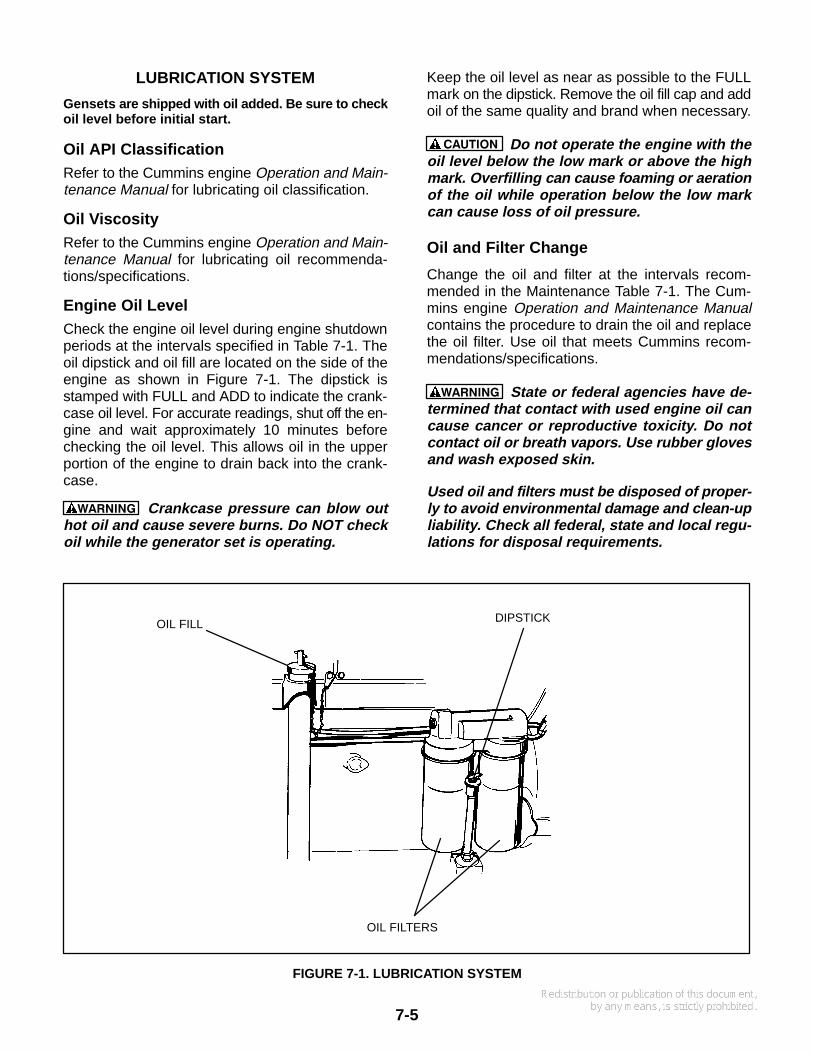
7-5
LUBRICATION SYSTEM
Gensets are shipped with oil added. Be sure to checkoil level before initial start.
Oil API ClassificationRefer to the Cummins engine Operation and Main-tenance Manual for lubricating oil classification.
Oil ViscosityRefer to the Cummins engine Operation and Main-tenance Manual for lubricating oil recommenda-tions/specifications.
Engine Oil LevelCheck the engine oil level during engine shutdownperiods at the intervals specified in Table 7-1. Theoil dipstick and oil fill are located on the side of theengine as shown in Figure 7-1. The dipstick isstamped with FULL and ADD to indicate the crank-case oil level. For accurate readings, shut off the en-gine and wait approximately 10 minutes beforechecking the oil level. This allows oil in the upperportion of the engine to drain back into the crank-case.
WARNING Crankcase pressure can blow outhot oil and cause severe burns. Do NOT checkoil while the generator set is operating.
Keep the oil level as near as possible to the FULLmark on the dipstick. Remove the oil fill cap and addoil of the same quality and brand when necessary.
CAUTION Do not operate the engine with theoil level below the low mark or above the highmark. Overfilling can cause foaming or aerationof the oil while operation below the low markcan cause loss of oil pressure.
Oil and Filter Change
Change the oil and filter at the intervals recom-mended in the Maintenance Table 7-1. The Cum-mins engine Operation and Maintenance Manualcontains the procedure to drain the oil and replacethe oil filter. Use oil that meets Cummins recom-mendations/specifications.
WARNING State or federal agencies have de-termined that contact with used engine oil cancause cancer or reproductive toxicity. Do notcontact oil or breath vapors. Use rubber glovesand wash exposed skin.
Used oil and filters must be disposed of proper-ly to avoid environmental damage and clean-upliability. Check all federal, state and local regu-lations for disposal requirements.
OIL FILL DIPSTICK
OIL FILTERS
FIGURE 7-1. LUBRICATION SYSTEM

7-6
BATTERIES
WARNING Ignition of explosive battery gasescan cause severe personal injury or death. Arc-ing at battery terminals, light switch or otherequipment, flame, pilot lights and sparks can ig-nite battery gas. Do not smoke, or switchtrouble light ON or OFF near battery. Dischargestatic electricity from body before touching bat-teries by first touching a grounded metal sur-face.
Ventilate battery area before working on or nearbattery—Wear goggles—Stop genset and dis-connect charger before disconnecting batterycables—Disconnect negative (–) cable first andreconnect last.
CAUTION Disconnect battery charger from ACsource before disconnecting battery cables.Otherwise, disconnecting cables can result involtage spikes damaging to DC control circuitsof the set.
Check the condition of the starting batteries at theinterval specified in the Maintenance Table. To pre-vent dangerous arcing, always disconnect the neg-ative ground cable from the battery before workingon any part of the electrical system or the engine.Disregard the sections On Checking Specific Gravi-ty and Checking Electrolyte Level if using a “mainte-nance-free” battery.
Cleaning Batteries
WARNING Electrolyte is a dilute sulfuric acidthat is harmful to the skin and eyes. Do not getthe substance in your eyes or contact with skin.Wear goggles and protective, rubber glovesand apron when servicing batteries.
In case of contact, immediately wash skin withsoap and water. In case of contact, immediatelyflood eyes with large amounts of water for aminimum of 15 minutes. IMMEDIATELY CALL APHYSICIAN.
Keep the batteries clean by wiping them with adamp cloth whenever dirt appears excessive.
If corrosion is present around the terminal connec-tions, remove battery cables and wash the termi-nals with a solution consisting of 1/4 pound of bak-ing soda added to 1 quart of water. (This solution isalso used for washing down spilled electrolyte.)
Be sure the vent plugs are tight to prevent cleaningsolution from entering the cells.
After cleaning, flush the outside of the battery andsurrounding areas with clean water.
Keep the battery terminals clean and tight. Aftermaking connections, coat the terminals with a lightapplication of petroleum jelly or non-conductivegrease to retard corrosion.
Checking Specific Gravity
Use a battery hydrometer to check the specificgravity of the electrolyte in each battery cell.
Hold the hydrometer vertical and take the reading.Correct the reading by adding four gravity points(0.004) for every ten degrees the electrolyte tem-perature is above 80° F (27° C). A fully charged bat-tery will have a corrected specific gravity of 1.260.Charge the battery if the reading is below 1.215.
Checking Electrolyte Level
CAUTION Do not add water in freezing weatherunless the engine will run long enough (two tothree hours) to assure a thorough mixing of wa-ter and electrolyte.
Check the level of the electrolyte (acid and watersolution) in the batteries at least every 200 hours ofoperation.
Fill the battery cells to the bottom of the filler neck. Ifcells are low on water, add distilled water and re-charge. If one cell is low, check case for leaks. Keepthe battery case clean and dry. An accumulation ofmoisture will lead to a more rapid discharge andbattery failure.
Battery Replacement
Always replace the starting battery with the samenumber and type (vented, lead acid). Properly dis-pose of battery in accordance with local environ-mental agency requirements.
WARNING Electrolyte or explosion of batterycan cause severe personal injury or death. Donot mutilate or burn the battery in a fire for dis-posal.
Damage to case will release electrolyte which isharmful to the skin and eyes and is also toxic.Burning of battery may cause an explosion.
7-7
COOLING SYSTEM
Gensets are shipped with coolant added. Be sure tocheck coolant level before initial start.
CAUTION The optional coolant heater mustnot be operated while the cooling system isempty or w hen the engine is running or damageto the heater will occur.
CAUTION Remove AC power to the heater be-fore disconnecting battery cables. Heater willrun continuously without DC power and canoverheat and damage heater.
CAUTION Do not add cold coolant to a hot en-gine. Engine castings can be damaged. Allowthe engine to cool to below 120 F (50 C ) beforeadding coolant.
Coolant LevelCheck the coolant level during shutdown periods atthe interval specified in Table 7-1. Remove the ra-diator cap after allowing the engine to cool and ifnecessary, add coolant until the level is about 3/4inch (18 mm) below the radiator cap lower sealingsurface. Use a coolant solution as recommended inthe Cummins engine Operation and MaintenanceManual.
WARNING To prevent severe scalding, let en-gine cool down before removing coolant pres-sure cap. Turn cap slowly, and do not open it ful-ly until the pressure has been relieved.
CAUTION Loss of coolant can allow engine tooverheat without protection of shutdown de-vice and cause severe damage to the engine.Maintain coolant level for proper operation ofthe high engine temperature shutdown system.
Cooling System MaintenanceHeavy duty diesel engines require a balanced cool-ant mixture of water and antifreeze. Drain and re-
place the mixture every year or after 500 hours ofoperation (whichever occurs first) to eliminate build-up of harmful chemicals.
Refer to the Cummins engine Operation and Main-tenance Manual for all cooling system mainte-nance, such as, coolant requirements, filling ofcooling system, coolant filter replacement andflushing and cleaning.
Radiator
Inspect the exterior of the radiator for obstructions.Remove all dirt or foreign material with a soft brushor cloth. Use care to avoid damaging the fins. Ifavailable, use low pressure compressed air orstream of water (maximum of 35 psi/242 kPa), inopposite direction of normal air flow to clean radia-tor. If using water, protect the engine and the gener-ator from over spray.
Coolant Heater
Check the operation of the coolant heater by verify-ing that hot coolant is being discharged from theoutlet hose. Do not touch outlet hose – if heater isoperational, radiant heat should be felt with handheld close to outlet hose.
WARNING Contact with cooling system or en-gine can result in serious burns. Do not touchcooling system or engine during genset mainte-nance until they are cool.
CHARGE-AIR PIPING
Inspect the charge air piping and hoses, daily, forleaks, holes, cracks, or loose connections. Tightenthe hose clamps if necessary.
FUEL SYSTEM
Refer to the Cummins engine Operation and Main-tenance Manual for fuel system maintenance.
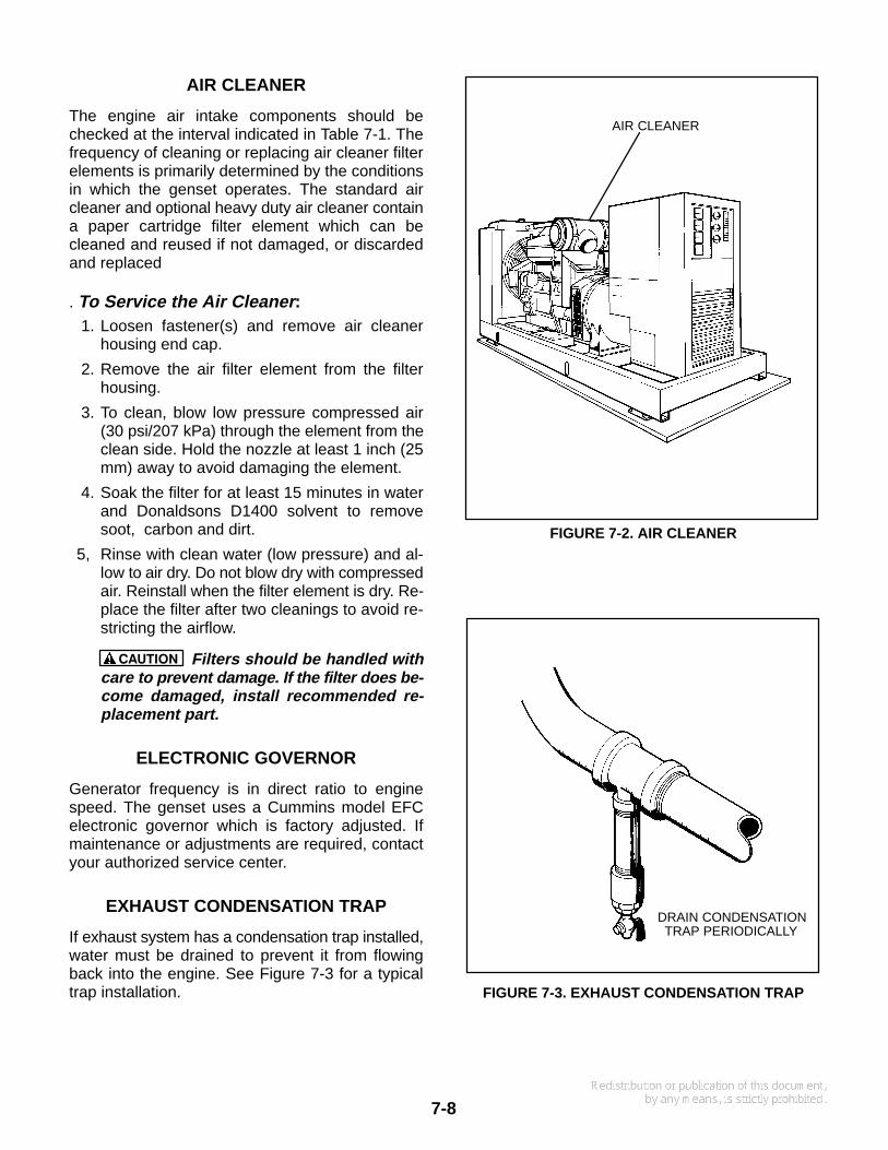
7-8
AIR CLEANER
The engine air intake components should bechecked at the interval indicated in Table 7-1. Thefrequency of cleaning or replacing air cleaner filterelements is primarily determined by the conditionsin which the genset operates. The standard aircleaner and optional heavy duty air cleaner containa paper cartridge filter element which can becleaned and reused if not damaged, or discardedand replaced
. To Service the Air Cleaner :1. Loosen fastener(s) and remove air cleaner
housing end cap.
2. Remove the air filter element from the filterhousing.
3. To clean, blow low pressure compressed air(30 psi/207 kPa) through the element from theclean side. Hold the nozzle at least 1 inch (25mm) away to avoid damaging the element.
4. Soak the filter for at least 15 minutes in waterand Donaldsons D1400 solvent to removesoot, carbon and dirt.
5, Rinse with clean water (low pressure) and al-low to air dry. Do not blow dry with compressedair. Reinstall when the filter element is dry. Re-place the filter after two cleanings to avoid re-stricting the airflow.
CAUTION Filters should be handled withcare to prevent damage. If the filter does be-come damaged, install recommended re-placement part.
ELECTRONIC GOVERNOR
Generator frequency is in direct ratio to enginespeed. The genset uses a Cummins model EFCelectronic governor which is factory adjusted. Ifmaintenance or adjustments are required, contactyour authorized service center.
EXHAUST CONDENSATION TRAP
If exhaust system has a condensation trap installed,water must be drained to prevent it from flowingback into the engine. See Figure 7-3 for a typicaltrap installation.
AIR CLEANER
FIGURE 7-2. AIR CLEANER
DRAIN CONDENSATIONTRAP PERIODICALLY
FIGURE 7-3. EXHAUST CONDENSATION TRAP
8-1
8. Operating Recommendations
NO-LOAD OPERATION
Periods of no load operation should be held to aminimum. If it is necessary to keep the engine run-ning for long periods of time when no electric outputis required, best engine performance will be ob-tained by connecting a load bank of at least 30 per-cent of nameplate rating.
EXERCISE PERIOD
Generator sets on continuous standby must be ableto go from a cold start to being fully operational in amatter of seconds. This can impose a severe bur-den on engine parts.
Regular exercising keeps engine parts lubricated,prevents oxidation of electrical contacts and in gen-eral helps provide reliable engine starting.
Exercise the generator set at least once a month fora minimum of 30 minutes, under not less than 30percent of the nameplate rating.
LOW OPERATING TEMPERATURE
Use a coolant heater if a separate source of poweris available. The optional heater will help provide re-liable starting under adverse weather conditions.Be sure the voltage of the separate power source iscorrect for the heater element rating.
CAUTION To avoid damage to heater, be surethe cooling system is full before applying powerto the heater.
HIGH OPERATING TEMPERATURE
Refer to the genset nameplate for the maximumambient operating temperature, if applicable.

8-2
THIS PAGE LEFT INTENTIONALLY BLANK

Cummins Power Generation1400 73rd Avenue N.E.Minneapolis, MN 554321-800-888-6626763-574-5000 International UseFax: 763-528-7229
Cummins is a registered trademark of Cummins Inc.