operator’s manual and parts list
TRANSCRIPT

OPERATOR’S MANUAL
AND PARTS LIST
PROGRESSIVE 12’ AND 15.5’ TRI-DECK
ROTARY FINISHING MOWERS
TD65-2: 12 FT. SERIAL NO. UP TO 1265-21375
TD65: 15.5 FT. SERIAL NO. UP TO 12651441
SERIAL # ______________________
Website: www.progressiveturfequip.com Issue Date: 01/10/2008 120512


DECLARATION OF CONFORMITY
According to Annex 11 A of the European Community Regulation for Machines
We, Progressive Turf Equipment Inc. 137 West William Street, Box 940, Seaforth Ontario, Canada declare under our
sole responsibility that:
Progressive Rotary Finishing Mowers
Models: Part Number Description
TD65-2
526512C, 526512D
3.66m Tri-Deck Finishing Mower
TD65 526515C, 526515D 4.72m Tri-Deck Finishing Mower
TD92 529222C 6.70m Tri-Deck Finishing Mower
PF-120 601205C, 601205D 3.05m Pro-Flex Contour Mower
PM-36 529236E 10.97m Pro-Max 36 Mowing System
TDR-22 526924E 6.70m Tri-Deck Roller Mower
TDR-15 528750C, 528750D 4.72m Tri-Deck Roller Mower
TDR-12 528712D 3.65m Tri-Deck Roller Mower
SDR-65 531965C 165cm Three Point Hitch Roller Mower
SDR-90 531990C 228.6cm Three Point Hitch Roller Mower
are in conformity with Directive 98/37/EC of the European Parliament and of the Council of 22 June, 1998 on the
approximation of the laws of the member states relating to Machinery.
The Technical Construction File is maintained at the corporate offices of Progressive Turf Equipment Inc. at the
address listed above.
Dated at Seaforth, Ontario Canada the 25th
day of January 2010.
Luke Janmaat
President
Progressive Turf Equipment Inc.


TABLE OF CONTENTS PAGE
INTRODUCTION
TO THE OWNER ……………………………………………..
GENERAL INFORMATION …………………………………
WARRANTY …………………………………………………
SPECIFICATIONS ……………………………………………
SAFETY RULES …………..…………………………………..
GENERAL SAFETY PRECAUTIONS ………………………..
OPERATING EQUIPMENT SAFELY ………………………..
MAINTENANCE SAFETY …………………………………...
WELDING & GRINDING WORK PRECAUTIONS …………
SAFETY CHAINS …………………………………………….
TRANSPORTING MOWER ………………………………….
TIRES …………………………………………………………
POWER TAKE OFF ………………………………………….
SAFETY DECAL LOCATIONS ………………………………
SAFETY DECALS ……………………………………… ASSEMBLY INSTRUCTIONS ………………………………..
3
4
5
6
7
8
9
10
11
12
12
13
13
14
15
18
OPERATION OF THE MOWER
DAILY CHECK LIST ………………………………………….
HITCHING MOWER TO TRACTOR ………………………….
LEVELING THE MOWER & PTO …………………………….
INSTALLING PTO SHAFTS …………………………………..
CHECKING PTO LENGTH DURING TURNS ……………….
CUTTING HEIGHT ADJUSTMENT …………………………..
GREASE COMPATIBILITY…………………………………….
LUBRICATION …………………………………………………
GEARBOX OIL LEVEL ………………………………………..
19
20
21
22
23
24
25
26
27
MAINTENANCE
MOWER BLADE SERVICING ……………………………….
BLADE REMOVAL & INSTALLATION ……………………
BLADE SHARPENING ……………………………………….
SPINDLE INSPECTION ………………………………………
SPINDLE ASSEMBLY REMOVAL ………………………….
SPINDLE ASSEMBLY INSTALLATION ……………………
ASSEMBLY OF SPINDLES ………………………………….
“V” BELT ADJUSTMENT ……………………………………
“V” BELT TENSION ………………………………………….
HYDRAULICS ………………………………………………..
TROUBLE SHOOTING ………………………………………
28
29
29
30
30
30
31
32
32
33
34
REPLACEMENT PARTS BOOK

3
TO THE OWNER:
Before you operate this mower, study this manual carefully. It has been
prepared to help you do a better and safer job of maintaining your mower.
Use only genuine Progressive Turf Equipment Inc. replacement parts.
Substitute parts will void the warranty and may not meet the standards required for
safe and satisfactory operation of this equipment.
Blades are especially important. Their manufacturing process is a very exacting one
and only a handful of blade producers are capable of this process. Always insist on
purchasing and using OEM blades for your own protection and that of your
employees.

4
GENERAL INFORMATION:
The purpose of this manual is to assist the operator in maintaining and
operating Progressive Turf Equipment mowers. Read it carefully. It furnishes
information and instructions that will help you achieve years of dependable
performance.
Some information may be general in nature due to unknown and varying
conditions. However, through experience and these instructions, you should be able
to develop operating procedures suitable to your particular situation.
Throughout this manual, references are made to right and left directions.
These are determined by standing at the rear of the equipment and facing the
direction of forward travel. Blade rotation is counter-clockwise as viewed from the
top of the mower.
For quick reference, record the following information.
MODEL: ___________________________
DATE PURCHASED: ___________________________
SERIAL NUMBER: ___________________________
For additional information, assistance during assembly, or operation of this mower,
contact the dealer from whom the machine was purchased.
5
WARRANTY POLICY
(To validate warranty, the Delivery and Warranty Registration form must
be completely filled out & mailed to Progressive Turf Equipment Inc.)
Progressive Turf Equipment Inc. warrants each new product to be free of defects in
material and workmanship to the original purchaser. Warranty will be applicable, from the
original date of purchase.
Pro-Flex120, TD65-2, TD65, TD92, TDR-15, TDR-12, TDR-22,
SDR-65, SDR-90, Pro-Max 36
FOR ALL APPLICATIONS - 24 MONTHS
This warranty coverage supersedes all written warranties, effective June, 2007..
This warranty will not cover any components which, in the opinion of the company, have
been subjected to negligent use, alteration, and accident, or if parts supplied by others have
been used in repairs of any product manufactured by Progressive Turf Equipment Inc.
Our obligation, in the event that any Progressive Turf Equipment Inc. product warranted,
shall become defective or fail, will be limited to repairing or replacing free of charge, or
provide labour and materials for the repair of, any defective part, subject to company
approval. All defective parts must be retained for 60 days after applying for warranty. Any
parts to be returned to Progressive Turf Equipment Inc. for inspection will be issued an
RGA number and must be returned within 14 days, transportation charges prepaid. This
warranty will not provide for service calls to customer location or for transportation of
equipment to dealer location if such servicing is required.
The sole liability of Progressive Turf Equipment Inc. under this warranty or any implied
warranty, shall be limited as set forth herein. The customer agrees that Progressive Turf
shall not in any event be obligated to reimburse, or pay the customer for any expense, loss
or any direct, incidental or consequential damages to any person or property for any reason
or caused by reason of Progressive Turf Equipment Inc., negligence, or otherwise in
connection with the sale, delivery, installation, training or use of the equipment. The
customer shall indemnify and hold Progressive Turf Equipment Inc. harmless against all
such liability.
This warranty is not subject to change or modification by anyone, including dealers, and
no one is authorized to make any representation on behalf of Progressive Turf Equipment
Inc.

6
MACHINE SPECIFICATIONS DESCRIPTION TD65-2 (12’) TD65 (15.5’)
Recommended HP 25-40 30-50
Cutting Width 12 ft. 15 ½ ft.
Transport Width 7 ½ ft. 8 ½ ft.
Height 5 ½ ft. 7 ½ ft.
Length 14 ft. 14 ft.
Ground Clearance 9 ¼” 9 ¼”
Spindles 7 9
Blades 3 per Centre Deck
2 per Wing Deck
3 per Deck
Weight 2380 lbs. 2720 lbs.
Tongue Weight Transport 445 lbs. 580 lbs.
Mowing 235 lbs. 330 lbs.
Mowing Capacity MPH 2
4
6
2.9 acres/hr
5.8 acres /hr
8.7 acres/hr
Assumes no stops or overlaps
3.75 acres/hr
7.5 acres/hr
11.3 acres/hr
360 Degree Turn 24” uncut circle 0” uncut circle
Ground Pressure 7 PSI 8 PSI
Tire to Ground 310 square inches of contact Castors 15 X 6. NHS – 4 ply pneumatic tires.
Number of Tires 10 on decks, 2 on main frame Transport Tires 18 X 9.5 NHS – 6 ply turf saver tires.
Deck Drive PTO shaft to right angle gear
box driving 2-“B” section belts
to 3 heavy-duty spindles.
Hydraulics Requires 1 double acting outlet, all
hoses supplied to tractor.
Belt Adjustment Easily made by loosening four
bolts at gearbox base and
adjusting the slide plate
forward or backward for
retightening.
Deck
Construction
3/16” steel plate formed and welded
with supporting members at high
stress areas to achieve maximum
strength. Deck is 5” deep.
Cutting Height Easy to use spacer bushings
allow adjustment from 1” to 5”
in 3/8” increments.
Hitch 4 position, with height settings from
10 ½” to 15”. Safety chain with hook
according to Dept. of Transport
regulations.
Spindles 1 3/16” dia. (30 mm) spindle is
carried in 2 re-greaseable ball
bearings, which are housed, in
a precision machined hub.
PTO Shafts Telescoping agricultural PTO shafts,
with proper safety shields. 1 3/8” – 6
spline quick-disconnect yokes on
both ends with Ring Lock collars.
INPUT PTO – Category # 4
DECK PTO – Category # 2
Blades High lift, heat treated, alloy
steel - 5/16” x 2 ½” x 23”.
Optional: Low lift blades
Speeds Tractor PTO – 540 RPM
Blades – 3040 RPM
Blade Tip Speed – 18,287 FPM
Anti-Scalp
Rollers
Standard on front of wing
decks.
Paint Finish Electrostatically painted with oven
baked finish.
Main Gearbox 4 shaft gearbox with 1 3/8 - 6
spline shafts
SMV Sign Located at back of mower for safety.
REAR DEFLECTOR AND MULCHING KITS AVAILABLE UPON REQUEST.
Design and specifications are subject to change without notice.

7
SAFETY RULES All rotary mowers are potentially dangerous machines; this mower has been designed to
minimize the safety risks to the operator, bystanders and property. This section of the
Operator’s Manual details a number of safety rules pertaining to the operation and
maintenance of Progressive Turf Equipment mowers. In order to minimize risks and
promote safety at all times, these rules must always be followed and obeyed.
Further safety rules and warning texts are given within the respective sections of this
manual.
IMPORTANT!
When it comes to safety, nothing will ever replace a careful operator.
It is imperative that the operator reads and understands all the safety information in this
manual before proceeding. Failure to follow the instructions or heed the warnings could
result in injury or death.
Proper care is your responsibility.
The manufacturer cannot anticipate every possible circumstance that might involve a
hazard. The hazard alerts in this publication and on the product, are therefore not all
inclusive. If a tool, procedure, work method, or operating technique not specifically
recommended by the manufacturer is used, it is your responsibility to ensure that it is safe
for you and others. You should also ensure the machine will not be damaged or made
unsafe by the operation, maintenance, or repair procedures you choose. Modifications or
adaptations to the machine are not allowed.
Various jurisdictions have specific requirements for work zone safety. Know and adhere to
your local requirements. Treat the instructions in this manual as minimum requirements for
safe operation.
SAFETY ALERT SYMBOL
This symbol appears at various points in the manual together with a
signal word and warning text. It means – Be alert! Your safety is
involved. This symbol is used throughout the manual to call attention to
areas in which carelessness or failure to follow specific procedures may
result in personal injury or component damage / malfunction or both.
HAZARD SERIOUSNESS LEVEL
The following signal words are found throughout the manual together with the safety alert
symbol to indicate the seriousness level of identified hazards. Their selection is based on
the consequence of human interaction with a hazard.
DANGER! –Hazards or unsafe practices which WILL result in
severe personal injury or death.
WARNING! – Hazards or unsafe practices that COULD result in
severe personal or death.

8
CAUTION! – Hazards or unsafe practices that COULD result in minor
personal injury or product or property damage.
GENERAL SAFETY PRECAUTIONS
The operator of this machine must have sufficient knowledge and instructions in the
care and operation of this mower and the power unit being used before he / she uses the
machine. Do not allow unauthorized persons or children to operate the machine. Do not
allow riders on the machine.
It is the obligation of the operator to make sure that all guards and shields are in place
on the machine. Safety decals must be in place and be readable – accidents may
otherwise occur. Contact your dealer or the manufacturer for replacement manuals or
decals.
Never use a machine that does not have an operator’s manual available. Learn and
understand the safety signs and symbols on the machine and the operator instructions
before you begin to use the machine.
Wear personal protective equipment. Know and use the protective
equipment that is to be worn when operating or servicing the
machine. Hard hats, protective glasses and face shields, protective
shoes, gloves, reflector type vests, and ear protection are types of
equipment that may be required. Prolonged exposure to loud noise
can cause hearing damage.
Never operate a mower while under the influence of drugs or alcohol. These make
reflexes slow and put you and others in grave danger. Always make sure you have full
concentration while mowing.
Adhere strictly to all regulations at the worksite pertaining to the operation of this
equipment.
Always disengage power takeoff (PTO) when transporting or traveling between work
sites.
Be prepared for emergencies. Have a first aid kit, fire extinguisher and emergency
contact information available at the work site.
POWER UNIT SAFETY
Operator must have sufficient knowledge in the care and operation of the power unit
(tractor) before connecting power unit to mower.
Power unit must be equipped with ROPS and seat belt. Foldable ROPS must be
secured in the upright position. Follow recommendations of power unit manufacturer.
Seat belt must be worn at all times.

9
Power unit must be equipped with a 1-3/8” 6 spline 540 RPM PTO connection. Never
use PTO adapters to connect implements. Never connect mower driveline to 1000
RPM PTO.
OPERATING EQUIPMENT SAFELY
Never allow persons to stand between power unit and mower while backing power unit
up to hitch the mower.
Before hitching mower to power unit, place transmission in neutral, set park brake, and
turn engine off. Remove the ignition key.
Make sure locking collar on PTO shaft is properly locked. If the PTO shaft comes off
during operation, personal injury or equipment damage could result.
Always install safety chains properly when hitching mower to power unit.
Tall grass can hide obstacles. Carefully walk the entire area to be mowed beforehand.
Look for debris, rocks, tree limbs etc. that will damage or be thrown by the mower
blades. Identify objects that cannot be removed. Set mower cutting
height to avoid contact.
Ensure that no bystanders are within 25 ft of mower when wing
transport locks are released.
Keep all bystanders well away from the machine when it is
operating. Always maintain a safe operating distance of 300 ft from
personnel, other equipment, or vehicles.
Never operate the mower with deflectors or guards removed. Mower blades can cause
small objects and debris to be thrown from under the mower deck at high speeds, up to
300 ft away. Objects ejected by the mower blades can cause severe injury.
Never tamper with safety devices or operate the mower with them removed. Check
proper operation regularly.
Always disengage PTO, turn power unit off and remove key before dismounting, for
any reason.
Never place hands or feet under mower deck when the mower is operating or power
unit engine is running.
Disengage the PTO when crossing gravel areas or roadways.
Disengage the PTO and turn power unit off upon striking any object. Inspect mower
and repair any damage before continuing.
If the equipment should start to vibrate abnormally during operation, stop the mower,
shut down power unit, and immediately check for the cause. Excess vibration is
generally an indication of a problem. Replace bent or damaged parts, do not attempt to
straighten a bent blade.
Use extreme care when operating on uneven terrain.
Reduce speed when operating on slopes during wet conditions, especially when making
sharp turns.

10
Do not use the mower in limited visibility (e.g. at dusk, in fog, heavy rain etc.). Mow
only in daylight or good artificial light.
Disengage PTO and ensure blades are completely stopped before raising wings.
Ensure transport locks are securely engaged before transporting mower with wings in
raised position.
Clean reflectors, Slow Moving Vehicle sign and lights before transporting. Use power
unit hazard lights.
Before disconnecting from power unit, always lower equipment to the ground, place
controls in neutral, set park brake, turn engine off, and wait for all moving parts to stop.
Relieve hydraulic pressure per power unit manufacturer’s instructions.
Ensure mower tongue jack is securely fastened to mower frame with supplied pin
before removing hitch draw pin.
MAINTENANCE SAFETY PRECAUTIONS
Never make adjustments or repairs with the engine running. Always disengage PTO,
turn engine off, lower wings to cutting position and relieve hydraulic pressure before
performing any maintenance.
Observe and perform proper lock-out procedures for power unit if attached to mower
during service.
Keep nuts and bolts tight and properly torqued, especially blade attachment bolts.
Check that all cotter pins are properly installed. Keep equipment in good condition.
Keep mower free of grass, leaves, or other debris build-up.
Never work on raised mower decks without safety locks in place.
Periodically check condition of safety devices, guards, and deflectors. Replace only
with manufacturer’s recommended parts.
Inspect and replace damaged blades. Use only original OEM parts. Blades can fail from
poor maintenance practices.
Handle mower blades carefully. They are sharp and can cut unprotected skin. Use
caution and wear gloves when handling them.
Check to make sure hydraulic hoses are not worn or damaged, and are routed to avoid
chafing.
Immediately replace any hydraulic hose that shows signs of swelling, wear, leaks or
damage so it does not burst.
Do not use your hand to check for hydraulic oil leaks. Use a piece of
cardboard instead. Hydraulic fluid escaping under pressure can penetrate
the skin causing serious injury. If skin penetration occurs, seek medical
attention immediately. Relieve all pressure before disconnecting hoses.
Do not bend or strike hydraulic lines, tubes or hoses, or reinstall them in a
bent or damaged condition.

11
Inspect tires daily for wear or damage. Check tire pressures weekly with an accurate
pressure gauge. Do not inflate tires beyond 35 psi.
Mounting and dismounting tires from rims can be dangerous and should be performed
by trained personnel using correct tools, equipment and procedures.
WELDING AND GRINDING WORK PRECAUTIONS
IMPORTANT! A fire extinguisher should be easily accessible during all welding
work.
Welding repairs are to be performed by a trained welder with proper service
instructions. Know the material to be welded and select the correct welding procedure
and materials (electrodes, rods, wire) that will provide a weld metal strength equivalent
to the parent material.
Move the machine to a clean, safe area before welding, grinding or using a cutting
torch on it. This type of work should only be done in a clean area and not in places that
contain combustible liquids, such as fuel tanks, hydraulic pipes or similar.
Connect arc welder ground as close as possible to work area.
Work with extra care when welding, grinding or torch cutting near flammable objects.
WORKING ON PAINTED SURFACES
Heated paint gives off poisonous gases. Therefore, paint must be removed from an
area with a radius of at least 4 in (10 cm) before carrying out welding, grinding,
or gas cutting. In addition to the health hazard, the weld will be of inferior
quality and strength if the paint is not removed.
Methods and precautionary measures when removing paint:
Blasting – use respiratory protective equipment and protective goggles.
Paint remover or other chemicals – use a portable air extractor, respiratory protective
equipment, and protective gloves.
Grinding – use a portable air extractor, respiratory protective equipment, and protective
gloves and goggles.

12
SAFETY CHAIN
It is recommended that the safety chain provided with this mower be attached to the
towing vehicle at all times.
Install a safety chain as shown. After attaching the safety chain, make a test run to the
left and right for a short distance to check for proper adjustment. Readjust to eliminate
a loose or tight chain.
TRANSPORTING MOWERS:
When traveling on public roadways, use flashing amber lights and S.M.V. emblem on rear
of mower to provide greater visibility to other traffic.
Once mower is in the raised position, activate tractor hydraulic control valve slightly so
that the cylinders will extend and allow the locks to be totally engaged. This way there
will be no sudden surges on the hydraulic system when traveling over tough terrain.
When towing this mower the following information concerning road speed should be
strictly adhered to.
WEIGHT OF TOWING
VEHICLE
MAXIMUM ALLOWABLE
ROAD SPEED
4500 LBS OR MORE UP TO 20 MPH (32 KM/H)
2300 LBS – 4500 LBS UP TO 10 MPH (16 KM/H)
2300 LBS OR LESS DO NOT TOW
Always have safety chain attached to towing vehicle.

13
TIRES
Upon receiving your mower, check air pressure in the tires and adjust according to
specifications.
TIRE TYPE RECOMMENDED TIRE
PRESSURE (PSI)
MOWER DECK TIRES
(CASTORS)
24 PSI
MAIN FRAME TIRES 32 PSI
Never inflate tires beyond 35 pounds per square inch (PSI) to seat beads. Inflation beyond
35 PSI pressure before seating the bead may break the bead or even the rim with an
explosive force. If beads have not seated by the time the pressure has reached 35 PSI,
deflate the assembly, move tire to another position on the rim and re-lubricate. Inflate tire
and inspect both sides of the tires to be sure beads are seated properly. If not, deflate tire,
unseat beads and repeat the above mounting procedure. After properly seating beads
adjust to pressure recommended.
POWER TAKE-OFF:
Keep all safety shields in place.
When operating the power take-off, be sure the tractor shield is always in place, covering
the exposed power take-off shaft.
Before dismounting from the tractor, stop the power take-off, put tractor in neutral, set
brakes in lock position and shut off engine.
When ready to engage PTO shaft, be sure engine RPM is at idle speed. Engaging PTO at
full throttle will cause high shock loads to driveline, with the potential for future failure.
Do not exceed the recommended PTO speed of 540 RPM.

14
SAFETY & MAINTENANCE DECAL LOCATIONS ON
MACHINE
ITEM
NO. DESCRIPTION
QTY ITEM
NO. DESCRIPTION
QTY
1 DANGER – READ MANUAL 1
10 NOTICE – HITCH
SETUP
1
2 CAUTION - TURNING 1 11 MOWER MODEL 2
3 CAUTION – REPLACE
SHIELDS
8 12
DANGER – OUTER
TUBE
3
4 COMPANY NAME 1 13 CE WARNING DECAL 1
5 WARNING - BLADE
HAZARD
7 14
SAFETY SIGN – INNER
GUARD
2
6 WARNING – OEM PARTS 1
15 SAFETY SIGN – OUTER
GUARD
2
7 CAUTION – DISENGAGE
PTO
1 16
DANGER – OUTER
SHIELD
3
8 GREASING SCHEDULE 1
9 PTO GREASING 1 GREASE POINT 20
5
11 (BOTH SIDES)
5
10 2 1
6
9
3 4
(2 SHAFTS) 13
14
15
12 (3 SHAFTS)
16
5
3
3
3
3
8
5
5
5
5

15
TD65 DECAL LISTING
If decals become faded, damaged, or lost, replace immediately. Order decal
according to corresponding Part # below. Complete decal kits are also available.
TD 65 15’ Decal Kit – 522303
TD 65 12’ Decal Kit – 522302
ITEM 1 ITEM 2 ITEM 2
(209175) (521819) (209171)
(A&C models only) (B&D models only)
ITEM 3
(209113)
ITEM 4
(521817)
ITEM 5
(209173)
ITEM 6
(209115)
ITEM 7
(521820) ITEM 8
(521119)
ITEM 9
(521199)
ITEM 10
(521784)

16
PROGRESSIVE PROGRESSIVE 65-2 TRI-DECK 65” TRI-DECK
ITEM 11 – TD 65-2 ITEM 11 – TD65
(521837) (521838)
ITEM 12
(521451)
ITEM 13
(210238)
ITEM 15
(210237)
ITEM 14
(210239)
GREASE POINT DECAL
(521014)
ITEM 16
(521455)

17
MAINTENANCE SAFETY
Never work on mower without safety locks in place, if decks are in raised
position.
Keep tractor and mower in good operating condition and all safety devices in
place.
Frequently check blade mounting bolts for tightness.
Periodically check to ensure all bolts are tight and that all nuts, screws and
cotter pins are properly installed to ensure that the mower is in a safe
condition.
PROPER TORQUE FOR FASTENERS
The chart lists the correct tightening torque for fasteners on Progressive Turf
Equipment mowers. When bolts are to be tightened or replaced, refer to this
chart to determine the proper torque except when specific torque values are
assigned in the manual. Only SAE grade 5 fasteners are to be used in the
assembly of this machine, or as otherwise specified in this manual.
Bolt Head Markings
SAE Grade 2 SAE Grade 5 SAE Grade 8
(No Dashes) (3 Dashes) (6 Dashes)
Bolt Diameter (in.)
(SAE Grade 5 Bolts)
Recommended Torque in
Foot Pounds (Newton-Meters)
5/16 21 (28)
3/8 38 (52)
7/16 55 (75)
½ 85 (115)
9/16 125 (170)
5/8 175 (240)
¾ 300 (410)
7/8 450 (610)
1 680 (925)
1” LH Spindle Nut 60 (82)

18
ASSEMBLY INSTRUCTIONS; TD65 MOWERS
1) Some assembly is necessary prior to pre-delivery inspection and delivery to the
customer.
2) The TD65 requires rear deck to be lifted from the frame assembly. Secure the
deck with lifting straps over the forks of a lift truck.
3) Lift the deck away and install the front castor wheels. Place the mower deck on
its wheels.
4) Remove parts that are strapped to the mower, such as the rear deck shaft, input
shaft, hose support, rear deck safety, hydraulic cylinder, hitch and hydraulic
hoses.
5) Unwrap the hydraulic hoses and pull rope. Then connect the hydraulic hoses to a
hydraulic source.
6) Secure the two rear lift arms before powering down the wings. They could fall
and damage the hydraulic components.
7) Remove the line pressure in the hydraulic hoses.
8) The rear deck safety and hydraulic cylinder are then installed with the pins
supplied. The safety goes on top of the cylinder and the pin holds both the safety
and cylinder. Be sure the cylinder is mounted on the stub end. Connect the pull
chain from the wing safety to the rear deck safety.
9) The long hose (31”) connects to the shaft end of the cylinder and is connected to
the bottom tee on the wing lock frame using the fittings supplied on the hoses.
The 90 degree fitting installs on the cylinder. The small hose (24”) is connected
to the stub end of the cylinder and at the top tee on the wing lock frame. Be sure
the 45 degree fitting is installed on the cylinder. Use thread sealant (Teflon tape)
on all joints.
10) Run the cylinders up and down 3 or 4 times to be sure that all air is out of the
system.
11) Roll the rear deck into place. Install lift arms with pins supplied on the deck.
12) Install deck shaft. Be sure that the end with the small bell marked with a tractor
goes on the four-way gear-box.
13) Remove intermediate shaft stub cover and install the input shaft. Be sure that the
small spacer bushing is in place and tighten the pinch bolt.
14) Install hose support shield. Make sure that the grease fitting on the hanger
bearing is visible through the hole in the shield for greasing. Run the safety pull
rope and hydraulic lines through the eye of the hose support rod.
15) Install the front hitch with the bolt provided.
16) Grease the front bearing, and the rear deck lift arms, and check over mower to
find any other spots that missed greasing (All spindles and wheels are greased
before shipping)
The mower is now ready for pre-delivery inspection.
19
OPERATING THE MOWER
A careful and knowledgeable operator is the best insurance against an
accident.
Allow no riders on any equipment.
If tractor is equipped with R.O.P.S., use the seat belt for maximum protection.
Make sure that everyone is clear of the tractor and mower before starting the
engine or operating.
DAILY CHECK LIST
1. Always wear relatively tight and belted clothing to avoid entanglement in
moving parts. Wear sturdy, rough soled work shoes. Never operate tractor or
implements in bare feet, sandals or sneakers.
2. Check that mower is properly and securely attached to tractor with a safety
chain.
3. Ensure all safety shielding is properly installed and check that all nuts and
bolts are secure and pins are properly secured with cotter pins.
4. Check condition of blades and security of attachment.
5. Ensure mower is properly mounted, adjusted and in good operating condition.
6. Clear area of stones, branches or other debris that might be thrown causing
injury or damage.
7. Never permit any person other than the operator to ride or board the tractor at
any time.
8. Check that all lubrication points with grease fittings have been lubricated as
per schedule.
9. Check all gearboxes for proper amount of gear oil. Mower must be on level
surface when this is done.
Be sure actuator pull rope is properly secured and will not become entangled
in PTO shaft.

20
HITCHING MOWER TO TRACTOR
Attach mower to drawbar only.
A & C MODELS ONLY
Drawbar should be adjusted so it is 14” to 15” from the center line of the
draw pin hole to end of PTO shaft. This is critical for proper PTO shaft
operation. (A & C MODELS ONLY)
Adjust hitch or drawbar so mower frame (Item #1, Page 33) is at the most
level position in relation with the ground. This will ensure proper flotation of
the wing decks.
Safety chain must always be attached to towing vehicle.
When towing mower on any roadways, lock brakes together. Use proper lighting
and marking devices according to the local regulations.
NOTE: If the three-point hitch is attached to tractor, be sure it will not contact any
part of the mower when making sharp turns. Mount the hose support bracket so the
large access hole is directly over the grease fitting on the hanger bearing. The hose
support rod may have to be bent back slightly to clear the three point hitch arms.

21
LEVELLING THE MOWER & PTO
For proper mower operation and maximum PTO life, the mower hitch and PTO
driveline must be setup correctly.
a) When the mower is connected to the tractor, the mower hitch frame “A”,
should be as close to level with the ground as possible.
b) The connecting hitch “B” can be removed and turned over to give more
height adjustments. Set in the best position for the mower frame to be as
level as possible.
c) To ensure proper life of the PTO shaft, the driveline from the mower gear
box “D” to the PTO shaft “E” on the tractor should be in a straight line.
CONNECTING THE PTO SHAFT
a) Ensure that the tractor engine is shut off and the parking brake is locked.
b) Holding the PTO against the end of the tractor PTO shaft, rotate the tractor
PTO by hand until the shaft slides on slightly.
c) Slide the locking collar on the PTO backwards, Push the PTO onto the
tractor PTO stub.
d) Release the locking ring and pull the PTO shaft backwards until the
locking mechanism snaps into place.
e) Push the shaft forward and backwards to ensure that this is securely locked
in place.
If the PTO shaft comes off during operation, it may cause personal injury and
damage to the PTO shaft and tractor PTO. When checking, make sure the locking
collar is locked, and that the shaft is not just jammed against the end of the tractor
PTO shaft.

22
INSTALLING PTO SHAFTS
The three identical PTO shafts are used to drive the mower decks. Each PTO shaft
will have one end designated a tractor end. This end should be hooked up to the
main gearbox.
The PTO shafts from the two wing decks must be timed when mounted to the
gearbox. See photo below. Mount the one side first with the yoke laying flat. The
opposite side must be mounted with the yoke lying as flat as possible. ie. Timed.
Input Drive Shaft
AlignYokes Align Yokes
Wing Deck PTO Wing Deck PTO
Rear Deck Drive Shaft
All PTO shafts have a short chain attached on both ends. Find a location to
wrap or hook on short chain. Be sure that when decks are brought into
transport position, the safety chain will not bind or pull PTO shield.
The Intermediate shaft is installed with the large bell end onto the main gear
box. Slide the 4 bolt flange bearing onto the intermediate shaft. Fasten the
flange bearing to the back side of the mounting plate. Install the shield and
level the PTO shaft. See section on “Hitching to the Tractor”.

23
CHECK PTO LENGTH DURING TURNS
During the mowing operation the tractor should be able to make turns without
damage to the driveline. To ensure proper setup, check the following conditions:
a) With the tractor and mower aligned, and the input PTO straight, turn the
shields on the input PTO to check that the holes line up for greasing the
input shaft tubes. If not, you will have to lengthen or shorten the drawbar.
(It should be 14” to 15” from the end of the PTO shaft to the center of the
drawpin hole. A & C models)
b) With the tractor in the lowest gear and traveling very slowly, make a sharp
turn to the right as required for mowing.
c) Watch the PTO shielding to make sure the PTO shaft does not totally
collapse. There should be 1” to 2” of inside PTO shielding left at
maximum turn. See picture below.
1” to 2” of inside shield showing
NOTE: This is not the worst condition. Making turns while the tractor is angling up
a hill will cause the PTO shaft to collapse even more. The operator should avoid
making sharp turns on uneven ground.

24
CUTTING HEIGHT ADJUSTMENT
Mower cutting height adjustment is made by removing lynch pin from the top
of each castor stem (square or round) and corner support and moving the
spacers either above or below support tube as required for your selected
cutting height.
NOTE: Cutting height starts at 1”, with no spacers under the bushing.
Adjust the height using 3/8” and 1” spacers.
Be sure all adjustments are set the same.
Spacers (3/8” & 1”)
Bushing

25
GREASE COMPATIBILITY
What Grease Is:
-Grease is essentially a distilled petroleum product in the form of mineral oil (or a
synthetic) which has a thickening agent such as lithium, calcium, barium, sodium, or
aluminum.
-Many of the thickeners will work for similar situations, but when mixing greases with
different thickeners, one must review compatibility. Grease incompatibility will actually
decrease the lubrication ability of the grease, and cause premature part failure.
-There may be other additives in the grease that impart special properties. These properties
may be “high temperature”, “extreme pressure”, etc.
What We Use:
- Our bearing supplier uses Shell Alvania 2
- Progressive uses Texaco Multifak EP 2
- EP means extreme pressure
- Both greases have: - A mineral oil base
- A lithium thickener
- The mineral oil has a NLGI Grade 2
- Both greases are compatible with each other
Note:
-If a thickener other than lithium is used, the existing grease will be contaminated and the
lubrication properties may be lost.
-If a synthetic base oil is used rather than a mineral base oil, the grease will again be
contaminated and the lubrication properties may be lost
-Molybdenum Disulfide (Moly) is an additive used in slow moving, extreme load
applications. The particles in the “Moly” will actually increase bearing wear in a mower
spindle. Our grease does not contain Moly.
-The blade spindle temperature should never go above 120°F if properly greased; we do
not recommend high temperature grease.
A grease with these features is considered to be a “General Purpose Grease”. Use on all
grease point locations on your Progressive Mower.
Our Recommendation for Grease Compatibility:
The grease you use for the blade spindle assemblies must have these properties:
NLGI grade 2
Lithium thickener (NOT LITHIUM COMPLEX OR LITHIUM 12-HYDROXY)
Kinematic Viscosity at 40°C is no greater than 190 cSt
Dropping Point Less than 400° F
General Purpose Grease, Not Heavy Duty
No MOLY (molybdenum disulphide) additives in the grease
No synthetic grease
No High Temperature Grease
Check the properties of the grease you wish to use with your supplier prior to use.

26
LUBRICATION
A properly maintained lubrication schedule will provide a smooth running machine for
many years. All pivot locations have grease fittings. The following information shows
and describes where all lubrication points are located.
DECKS P.T.O. SHAFTS FRAME
Spindles* (See Manual)
3 Pivots per Wing
Deck*
2 Pivots on Rear Deck*
Castor Wheel &
Swivels* *As Required
Main Input*(See
Below)
Deck Drive, 4
Locations per Shaft*
Pull Apart Sliding
Tubes once per week and
lubricate
*As Required
8 Pivot Locations*
2 Wheels*
*As Required
CHECK FOR PROPER OIL LEVEL IN GEARBOXES DAILY
GREASING SCHEDULE & LOCATION
BLADE SPINDLE GREASING:
The top bearing on all spindle assemblies has a shield only. This allows grease to exit
and relieves any pressure build up inside spindle housing, when greasing. Greasing of
blade spindles should continue until grease can be seen exiting between the top bearing
and the bottom of hub on pulley. Some working conditions will require this operation
to take place every 4 to 5 running hours because of hot working areas. Cooler working
areas will only require greasing every 8 to 10 hours. A proper greasing schedule can
only be determined by operator, depending on working conditions in your particular
area.

27
GEARBOX OIL LEVELS
IMPORTANT! DO NOT OVERFILL! MOWER MUST BE LEVEL WHEN
CHECKING GEARBOX OIL LEVEL
DECK GEARBOXES:
Gearboxes all have an oil level plug located on the side of the gearbox. Oil should
reach the bottom of this hole. If oil level is low, add oil through top plug hole of casing
until oil just starts to flow out of side oil level hole. Replace and tighten plugs. Use
80W90-gear oil or equivalent.
Filler Plug
Level Plug
MAIN GEAR BOX:
The main gearbox has a combination filler plug and dipstick. Remove the plug, dry
off the dipstick and replace to check oil level. It must touch the oil in the gear box.
Add oil as required. Use 80W90 gear oil or equivalent. Replace and tighten the plug.

28
MAINTENANCE
Turn tractor engine off before performing any maintenance.
Always use personal protection devices such as eye and ear protectors when
performing maintenance functions.
When completing a maintenance or service function, make sure all safety
shields are installed before placing mower in service.
BLADE SERVICING
Be sure safety locks are in place when working on decks in the raised
position. The tractor hydraulic system could fail, causing decks to fall and
crush anything under them.
Do not handle mower blades with bare hands. Careless or improper handling
may result in serious injury.
Inspect blades before each use to determine that they are mounted tightly and
are in good condition. Replace any blade that is bent, excessively nicked,
worn or has any other damage. Small nicks can be ground out when
sharpening.
Only original equipment blades should be used when replacing worn out
mower blades. They are made of special steel alloys and subjected to rigid
heat-treat and inspection requirements. Substitute blades may not meet these
rigid specifications and MAY BE DANGEROUS.

29
BLADE REMOVAL AND INSTALLATION
Two, 1/2” X 1 3/4” grade 5 bolts with lockwashers and nuts hold blade to blade
spindle support bar. When changing blades, be sure that these fasteners are in good
condition so they will not come loose during operation.
BLADE SHARPENING
IMPORTANT - When sharpening blades be sure to balance them. Unbalanced
blades will cause excessive vibration, which can damage blade spindle bearings.
Vibration may also cause structural cracks in spindle housing.
Follow original sharpening pattern as shown. Sharpen blade to a razor edge.
Protect hands when sharpening. Do not sharpen backside of blade.
BLADE SHARPENING

30
SPINDLE INSPECTION
Spindles are equipped with two roller ball bearings. Adjustment is set by
tightening the 1” left hand nut to 60 ft-lbs. torque for proper setting.
Periodically inspect blade spindles by grasping blade, and moving from side
to side. If any free play is noted, replace or repair.
SPINDLE ASSEMBLY REMOVAL
1. Remove blade from spindle.
2. Remove belt shield. Loosen 4 bolts that hold gearbox to mount.
3. Loosen 1/2” x 3 1/2” tap bolts and slide gearbox toward front until belt is
easy to remove.
4. Remove belt.
5. Remove 4 bolts attaching spindle assembly to mower frame and remove as a
unit, since pulley will come out through the hole in the deck.
SPINDLE ASSEMBLY INSTALLATION
Reverse above procedure. Be sure spindle mounting area of deck is clean of any
foreign material before attaching spindle assembly.
SPINDLE REPAIR
Spindle repair requires special skills and tools. If your shop is not properly
equipped or your mechanics are not properly trained in this type of repair, you
may be time and money ahead to use a new spindle assembly.
Remove pulley from spindle assembly. Place assembly in press and force
spindle down through housing. Once pressed apart, replace bearings, as
removal will have damaged bearings internally.

31
ASSEMBLY OF SPINDLE
Only use a press that has the ram and bed 100% square to each other. If
bearings are not square in housing, bearings will wear out prematurely. Press
on outer race when inserting into hub and press on inner race when installing
on spindle.
If bearings are being changed, be
sure to check bearing spacer for
wear. If wear is noticed, insert new
spacer. This is critical because if
spacer is short by only .010”, the
top bearing will start to bind and
will result in premature failure.
Bearing with seal and shield
combination will be pressed into
the blade side of the hub first with
the seal side facing out. Next, set
spindle on press bed, install dirt
shield and shim first (as per
diagram) set hub, bearing end
down, onto spindle. You must use a
tube (Note: both ends must be
square) which will slide over
spindle and press on inner race of
bearing, until seated against shim.
Insert bearing spacer tube with hole end up. Set remaining bearing with
shield side up, open side on first, onto spindle. Press on inner race (this
bearing will be a loose fit in the hub so it will seat itself properly).
When all parts have been installed on spindle, torque left hand nut to 60 ft-
lbs. and then tighten set screws in pulley. Once the assembly is complete, fill
with quality grease until it can be seen exiting the top bearing. Rotate the
housing six revolutions by hand so the bearings will have the grease worked
into them, and at the same time check for free movement. The assembly is
now ready for installation into the mower deck.

32
“V” BELT ADJUSTMENT
Begin by loosening 4 bolts at the base of the gearbox. Adjusting long
threaded bolt slides the gearbox back, tightening belt. After proper tension is
achieved, tighten 4 bolts at base of gearbox. You may have to place a ½” nut
under the head of the long threaded bolt to increase your adjustment length.
When changing belts, removal of grease fitting from the top of the center
spindle will make installation easier. Be sure belts run in proper groove.
“V” BELT TENSION
Proper belt tensioning is a fundamental factor in the successful V-belt
operation. Lack of tension will cause slippage, and too much tension will
cause excessive belt stretch as well as damage to the drive components, such
as bearings and shafts. Therefore, to ensure proper belt tension, the following
procedure is recommended.
CHECKING BELT TENSION
At the mid-point of the span, apply a deflection force with a spring scale in
the direction perpendicular to the span until the belt is deflected the 3/8”.
The recommended force to deflect the belt is a minimum of 4.9 lbs. to a
maximum of 7.3 lbs.
The first 24 to 48 hours of operation is the belt “run in” period. To ensure
satisfactory belt performance, belt tension should be checked during this time
period.
33
HYDRAULICS:
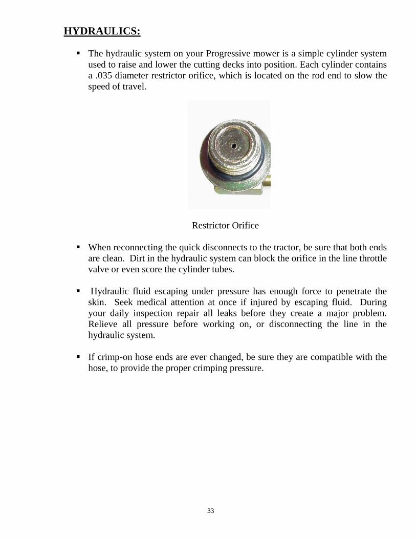
The hydraulic system on your Progressive mower is a simple cylinder system
used to raise and lower the cutting decks into position. Each cylinder contains
a .035 diameter restrictor orifice, which is located on the rod end to slow the
speed of travel.
Restrictor Orifice
When reconnecting the quick disconnects to the tractor, be sure that both ends
are clean. Dirt in the hydraulic system can block the orifice in the line throttle
valve or even score the cylinder tubes.
Hydraulic fluid escaping under pressure has enough force to penetrate the
skin. Seek medical attention at once if injured by escaping fluid. During
your daily inspection repair all leaks before they create a major problem.
Relieve all pressure before working on, or disconnecting the line in the
hydraulic system.
If crimp-on hose ends are ever changed, be sure they are compatible with the
hose, to provide the proper crimping pressure.
34
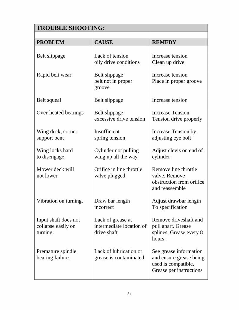
TROUBLE SHOOTING:
PROBLEM CAUSE REMEDY
Belt slippage Lack of tension
oily drive conditions
Increase tension
Clean up drive
Rapid belt wear Belt slippage
belt not in proper
groove
Increase tension
Place in proper groove
Belt squeal Belt slippage Increase tension
Over-heated bearings Belt slippage
excessive drive tension
Increase Tension
Tension drive properly
Wing deck, corner
support bent
Insufficient
spring tension
Increase Tension by
adjusting eye bolt
Wing locks hard
to disengage
Cylinder not pulling
wing up all the way
Adjust clevis on end of
cylinder
Mower deck will
not lower
Vibration on turning.
Input shaft does not
collapse easily on
turning.
Premature spindle
bearing failure.
Orifice in line throttle
valve plugged
Draw bar length
incorrect
Lack of grease at
intermediate location of
drive shaft
Lack of lubrication or
grease is contaminated
Remove line throttle
valve, Remove
obstruction from orifice
and reassemble
Adjust drawbar length
To specification
Remove driveshaft and
pull apart. Grease
splines. Grease every 8
hours.
See grease information
and ensure grease being
used is compatible.
Grease per instructions

35

TD65-2 & TD65 ROTARY FINISHING MOWER
PARTS MANUAL
TABLE OF CONTENTS
ITEM DESCRIPTION PAGE
1 SPINDLE ASSEMBLY ---------------------------------------------------------------------2
2 MOWER WING DECKS TD65-2 --------------------------------------------------------------4
3 MOWER WING DECKS TD65 -------------------------------------------------- 6
4 REAR DECK ASSEMBLY --------------------------------------------------------8
5 MAIN FRAME ASSEMBLY --------------------------------------------------------------------------------10
6 WING DECK LIFT --------------------------------------------------------------------------------12
7 HYDRAULIC COMPONENT ASSEMBLY ----------------------------------------------------14
8 DRIVE COMPONENT ASSEMBLY -----------------------------------------------------------------------------------16
9 WHEEL ASSEMBLIES ----------------------------------------------------------------------------------------------18
10 DECK GEARBOX ASSEMBLY -------------------------------------------------20
11 4-WAY GEARBOX ASSEMBLY ---------------------------------------------------------------22
12 DECK PTO ASSEMBLY ---------------------------------------------------- 24
13 INTERMEDIATE PTO ASSEMBLY A & C MODELS--------------------- 26
14 INPUT PTO ASSEMBLY A & C MODELS---------------------------------- 28
15 INTERMEDIATE PTO ASSEMBLY B & D MODELS--------------------- 30
16 INPUT PTO ASSEMBLY B MODEL----------------------------------------- 31
17 INPUT PTO ASSEMBLY D MODELS--------------------------------------- 33
Website: www.progressiveturfequip.com Revision Level: 3
Issue Date: 06/30/2009


BLADE SPINDLE - MODEL TD65
ITEM PART # DESCRIPTION 15.5' Serial No. QTY. 12' Serial No. QTY.
1 O.L. 1/4 - 28 GREASE FITTING 9 7
2 521003 LEFT HAND NUT 9 7
3 521002 LEFT HAND LOCK WASHER (3PC/KIT) 3 KITS 3 KITS
4 521773 2HB 4.4 X 1 1/8" PULLEY (RED) (A,B,C MODELS) 9365276 & Above 9 9365-2044 & Above 7
521300 2HB 4.4 X 1 1/8" PULLEY (BLACK) 9165101 to 9365275 9 9265-2002 to 9365-2043 7
5 521790 5.95" OD X 1-1/8" HUB PULLEY (D MODELS) 9 7
6 521301 1" SHIM WASHER (9PC/KIT) 1 KIT 1 KIT
7 521302 TOP BEARING, STEEL SHIELD UP 9 7
6206ZC3
8 521700 SPINDLE HOUSING (RED) 9165176 & Above 9 7
521303 SPINDLE HOUSING (BLACK) N/A 9165101 to 9165175 N/A N/A
9 521304 BEARING SPACER TUBE 9 7
10 521701 BOTTOM BRG, STEEL SHIELD UP 9 7
6206LBZC3/2AS
11 521305 1" SHIM WASHER (9PC/KIT) 1 KIT 1 KIT
12 521306 DIRT SHIELD (3PC/KIT) 3 KITS 3 KITS
13 O.L. 1/4" SQ. X 1 11/16" KEY 9 7
14 521307 BLADE SPINDLE 9 7
MOWER BLADES KITS
15 522603 5/16" X 2 1/2" X 23" - O.E.M. 9/KIT
522604 5/16" X 2 1/2" X 23" - O.E.M. 7/KIT
522606 5/16" X 2 1/2" X 23" - LOW LIFT 9/KIT
522607 5/16" X 2 1/2" X 23" - LOW LIFT 7/KIT
522611 MULCHING BLADE 9/KIT
522612 MULCHING BLADE 7/KIT
522506 MULCH HOOP KIT 12' (TD65-2) 1
522507 MULCH HOOP KIT 15' (TD-65) 1
16 O.L. 1/2" X 1 3/4" BOLT, LOCKWASHER, NUT 24 20
17 O.L. 7/16" X 1 1/2" BOLT, LOCKWASHER,NUT 36 28
4.4" PULLEY
18 521776 COMPLETE SPINDLE ASSEMBLY(A,B,C MODELS) 9365276 & Above 9 9265-2044 & Above 7
521340 SPINDLE ASSEMBLY LESS PULLEY(ALL MODELS) 9365276 & Above 9 9265-2044 & Above 7
521702 COMPLETE SPINDLE ASSEMBLY 9365176 to 9365275 9 9265-2002 to 9365-2043 7
521309 COMPLETE SPINDLE ASSEMBLY N/A 9165101 to 9365175 N/A N/A
5.9" PULLEY
19 521792 COMPLETE SPINDLE ASSEMBLY(D MODELS) 9 7
OL - Obtain Locally AR - As Required QTY - Total Number Required for Complete Machine
Rev. 2, JUNE 09
3


WING DECK - MODEL TD65-2 - 12'
ITEM PART # DESCRIPTION 12' Serial No. QTY
1 521707 44" RH MOWER DECK 1
521706 44" LH MOWER DECK 1
2 O.L. 7/16" X 1" BOLT, LOCK, NUT 18
3 O.L. 1/4" - 28 GREASE FITTING 20
4 521315 B69 BELT (A,B,C MODELS) 4
212040 B75 BELT (D MODELS ONLY) 4
5 521818 1" GRAPH OIL BUSHING (PRESS IN) 12
521818.10 1" GRAPH OIL BUSHING 10 PACK 2
6 522312 1" X 9 3/8" CORNER PIN 9765-2342 AND ABOVE 2
521312 1" X 9" CORNER PIN 9365-2002 TO 9765-2341 2
7 521021 1" X 1" RD SPACER (6 PC/ KIT) 3 KITS
8 521022 3/8" 1" RD SPACER (6 PC/KIT) 3 KITS
9 521038RD 5/16" LYNCH PIN (4PC/ KIT) 2 KITS
10 521704 LH BELT GUARD 2
521705 RH BELT GUARD 2
11 521013 SLIDE PLATE 3
12 521004 1 1/4" SHIM WASHER (9 PC KIT) 1 KITS
13 O.L. 9/16" X 2" BOLT AND LOCK 12
14 521012 DECK GEARBOX LF141A 3
15 521390 KEY - 1/4" X 1/4" X 1 5/16" (KIT 3 PCS) 3 KITS
16 521020 1/2" X 3 1/2" TAP BOLT (3 PC/KIT) 1 KIT
17 521019 GEARBOX MOUNT 3
18 521018 STIFFENER NUT BRACKET 6
19 O.L. 3/8" WING NUT, FLAT WASHER 16
20 521703 BELT GUARD SMALL 2
21 521129 WASHER - 25 X 44 X 4 (3 PC/KIT) 1 KIT
22 521130 CASTELLATED NUT M24 X 2 3
23 O.L. 3/16" X 2 1/4" COTTERPIN 3
24 521774 MAIN DRIVE PULLEY 8.7" (A,B,C MODELS) 9465-2044 AND ABOVE 3
212021 MAIN DRIVE PULLEY 11 1/4" (D MODELS) 3
521035 MAIN DRIVE PULLEY (BLACK) 9365-2002 TO 9365-2043 3
25 209001 ANTI-SCALP ROLLER - 4 1/4" 6
26 521750 ANTI-SCALP PIN 5 7/8" + COTTERPIN 6
O.L. - Obtain Locally AR - As Required QTY - Total Number Required for Complete Machine
Rev. 2, JUNE 09
5


WING DECK - MODEL TD65 - 15.5' Rev. 2,AUG 07
ITEM PART # DESCRIPTION 15.5' Serial No. QTY
1 521314 65" R. H. MOWER DECK 1
521313 65" L. H. MOWER DECK 1
2 O.L. 7/16" X 1" BOLT, LOCK, NUT 18
3 521750 5/8" X 5 7/8" PIN & COTTERPIN 2
521316 5/8" X 7 1/2" PIN & COTTERPIN 9165101 TO 9865587 2
4 209001 4" ANTI-SCALP ROLLER 2
521026 4" x 6" ANTI-SCALP ROLLER 9165101 TO 9865587 2
5 521315 B69 BELT (A,B,C MODELS) 6
212040 B75 BELT (D MODEL ONLY) 6
6 O.L. 1/4" - 28 GREASE FITTING 20
7 521818 CASTOR ARM, PIVOT BUSHING 12
521818.10 1" GRAPH OIL BUSHING 10 PACK 2
8 522312 1" X 9 3/8" CORNER PIN 2
521312 1" X 9" CORNER PIN 2
9 521021 1" X 1" RD SPACER (6 PC/ KIT) 3 KITS
10 521022 3/8" 1" RD SPACER (6 PC/KIT) 3 KITS
11 521038RD 5/16" LYNCH PIN (4PC/ KIT) 2 KITS
12 521704 LH BELT GUARD 3
13 521013 SLIDE PLATE 3
14 O.L. 9/16" X 2" BOLT AND LOCKWASHER 12
15 521012 DECK GEARBOX LF141A 3
16 521390 KEY - 1/4" X 1/4" X 1 5/16" (KIT 3 PCS) 1 KIT
17 521004 1 1/4" SHIM WASHER (9 PC KIT) 1 KIT
18 521020 1/2" X 3 1/2" TAP BOLT (3 PC/KIT) 1 KIT
19 521019 GEARBOX MOUNT 3
20 521018 STIFFENER NUT BRACKET 6
21 521705 RH BELT GUARD 3
22 O.L. 3/8" WING NUT, FLAT WASHER 18
23 521130 CASTALATED NUT M24 X 2 3
24 521129 WASHER - 25 X 44 X 4 (3 PC/KIT) 1 KIT
25 O.L. 3/8" X 2 1/4" COTTERPIN 3
26 521774 MAIN DRIVE PULLEY (A,B,C MODELS) 9465276 & ABOVE 3
212021 MAIN DRIVE PULLEY (D MODEL ONLY) 3521035 MAIN DRIVE PULLEY 9165101 TO 9465275 3
OL - Obtain Locally AR - As Required QTY - Total Number Required for Complete Machine
7


REAR DECK - 15.5' & 12' Rev. 1, OCT 05
ITEM PART # DESCRIPTION 15.5' Serial No. 12' Serial No. QTY
1 521354 REAR MOWER DECK 1
2 521705 R.H. BELT GUARD 3
3 521349 REAR DECK LIFT ARM 2
4 521704 L.H. BELT GUARD 3
5 521337 1" X 6 1/4 DECK LIFT PIN-SHORT 9765545 & ABOVE 9765-2342 & ABOVE 6
521395 1" X 6 1/2 PIVOT PIN 9465276 TO 9765544 9465-2044 TO 9765-2341 6
521351 1" X 6 1/2 PIVOT PIN 9165101 TO 9465275 9365-2010 TO 9365-2043 6
6 O.L. 3/8" X 2" BOLT, LOCK, NUT 6
7 521353 S.M.V. SIGN 1
8 O.L. 1/4" X 3/4" BOLT, LOCK, NUT 2
9 521012 DECK GEARBOX LF141A 3
OL - Obtain Locally AR - As Required QTY - Total Number Required for Complete Machine
9


MAIN FRAME - 15.5' & 12' Rev. 2, JUNE 09
ITEM PART # DESCRIPTION 15.5' Serial No. 12' Serial No. QTY
1 521870 MAIN FRAME 9651371 & ABOVE 0965-21295 & ABOVE 1
2 521358 RH WING 1
3 O.L. 1/4" - 28 90° GREASE FITTING 4
4 521356 1" X 21" WING PIN 2
5 O.L. 3/8" X 1 1/2" W/ LOCK, NUT, 2 FLAT 4
6 521325 WING LOCK FRAME MT BRKT 2
7 521322 4 POSITION HITCH 1
8 521048 SAFETY CHAIN 1
9 O.L. 3/8" X 1 1/4" W/ LOCK, NUT, FLAT 6
10 521324 IMPLEMENT JACK 1
11 528192 FRONT SHIELD MT C.V (B&D MODELS) 1
12 528196 FRONT SHIELD MT. NON C.V.(A&C MODELS) 1
13 O.L. 3/4" X 5"BOLT, NUT & LOCK 1
14 528190 INTERMEDIATE MOUNT (B&D MODELS) 1
15 521355 LH WING 1
16 O.L. 1/2" X 6" BOLT, LOCK, NUT 4
17 O.L. 3/8" X 1 1/4 BOLT WITH LOCKWASHER 4
18 521331 PULL ROPE 10' 1
19 521329 WING LOCK FRAME 1
20 521330 WING SAFETY LOCK 1
21 O.L. 3/8" X 1 1/4" W/FLATS, NUT, LOCK 2
22 521064 SAFETY SPRING 1
23 521332 PULL CHAIN 23 1/4" 1
24 521081 1" X 5 5/16" PIN - REAR CYLINDER 1
25 O.L. 1/2" X 1 3/4" BOLT, NUT 2
26 528198 FENDER BRACKET L.H. 1
27 521841 REAR DECK SAFETY 9765545 & ABOVE 9765-2342 & ABOVE 1
521763 REAR DECK SAFETY 9465276 TO 9765544 9465-2044 TO 9765-2341 1
521348 REAR DECK SAFETY 9165101 TO 9465275 9365-2010 TO 9365-2043 1
28 522301 REAR DECK PICK UP FRAME 9565588 & ABOVE 9865-2423 & ABOVE 1
521708 REAR DECK PICK UP FRAME 9165101 TO 9865587 9365-2010 TO 9865-2422 1
29 521349 REAR DECK LIFT ARM 2
30 521094 LIFT ARM PIVOT PIN -1" X 9 3/4" 231 O.L. GREASE FITTING - STRAIGHT 2032 528200 FENDER BRACKET R.H. 133 521321 MAIN FRAME 9165101 TO 9651371 9365-2010 TO 0965-21295 1
OL - Obtain Locally AR - As Required QTY - Total Number Required for Complete Machine
11


WING LIFT - 15.5' & 12' Rev. 1, OCT 05
ITEM PART # DESCRIPTION 15.5' Serial No. 12' Serial No. QTY
1 O.L. 3/8" X 2" BOLT, LOCK, NUT 6
2 521337 1" X 6 1/4 DECK LIFT PIN - SHORT 9765545 & ABOVE 9765-2342 & ABOVE 6
521395 1" X 6 1/2 PIVOT PIN 9465276 TO 9765544 9465-2044 TO 9765-2341 6
521351 1" X 6 1/2 PIVOT PIN 9165101 TO 9465275 9365-2010 TO 9365-2043 6
3 O.L. 1/4" - 28 GREASE FITTING 20
4 521710 DECK SWIVEL TD65-2 (12' MOWER) 2
521357 DECK SWIVEL TD65 (15.5' MOWER) 2
5 521358 R.H. WING 1
521355 L.H. WING 1
6 521102 1/2" X 3 1/2" SPADE BOLT, 1/2" NUTS 2
7 521431 2" X 10" SPRING 2
8 521338 1 1/4" X 16 3/4" SWIVEL PIN 9465295 & ABOVE 9465-2044 & ABOVE 2
521097 1 1/4" X 17" SWIVEL PIN 9165101 TO 9465294 9365-2010 TO 9365-2043 2
9 O.L. 3/8" X 2 1/4" BOLT, NUT, LOCK 2
OL - Obtain Locally AR - As Required QTY - Total Number Required for Complete Machine
13


HYDRAULIC ASSEMBLY - 15.5' & 12' Rev. 1, OCT 05
ITEM PART # DESCRIPTION 15.5' Serial No. 12' Serial No. QTY
1 521345 1" X 2.938" PIN AND CLIPS 2
2 521814 SEAL KIT FOR 2 1/2" CYLINDER 9865588 & ABOVE 9865-2423 & ABOVE -
521477 SEAL KIT FOR 2 1/2" CYLINDER 9165101 TO 9865587 9365-2010 TO 9865-2422 -
3 522300 2 1/2" HYDRAULIC CYLINDER 9865588 & ABOVE 9865-2423 & ABOVE 3
521333 2 1/2" HYDRAULIC CYLINDER 9165101 TO 9865587 9365-2010 TO 9865-2422 3
4 521336 90° 3/8" RESTRICTOR ( 0.035) 9465276 &ABOVE 9465-2044 & ABOVE 3
222015 RESTRICTOR KIT (W/ 31" HOSE - EXTRA) 9165101 TO 9465275 9365-2010 TO 9365-2043 2
5 521769 31" HYDRAULIC LINE 9465276 &ABOVE 9465-2044 & ABOVE 3
521339 26" HYDRAULIC LINE 9165101 TO 9465275 9365-2010 TO 9365-2043 3
6 521063 45 DEGREE SWIVEL STREET ELBOW 9465276 &ABOVE 9465-2044 & ABOVE 3
521347 45 DEGREE SWIVEL STREET ELBOW 9165101 TO 9465275 9365-2010 TO 9365-2043 3
7 521335 24" HYDRAULIC LINE 3
8 521081 1" X 5 1/4" PIN- REAR CYLINDER 1
9 521103 1" X 4 3/4" PIN - WING CYLINDER 2
10 521416 MALE BRANCH TEE 9465276 &ABOVE 9465-2044 & ABOVE 2
11 521770 3/8" TEE 9465276 &ABOVE 9465-2044 & ABOVE 2
12 521073 FLOW DIVIDER 1
222016 FLOW DIVIDER KIT 9165101 TO 9465275 9365-2010 TO 9365-2043 1
13 521334 110" HYDRAULIC LINE 2
14 521051 HYDRAULIC HOSE CLAMP 1
15 O.L. 3/8" LOCKNUT 1
16 521071 "U" BOLT, NUTS, AND LOCKS 2
17 222006 HOSE END - 1/2" (2PCS/KIT) 1 KIT
18 521342 1/2" NPT TO JIC ADAPTER 2
19 521077 LINE THROTTLE VALVE 2
20 521343 REDUCING BUSHING 1
21 521344 90 DEG. ELBOW, MALE TO MALE 1
22 521391 3/8" TO 1/2" MALE NIPPLE 1
23 521392 45 DEG STREET ELBOW 1
24 521341 3/8" STRAIGHT SWIVEL ADAPTER 125 521350 1" x 3.563" PIN 1
521067 1" X 6 1/2" PIN (REAR) 9165101 TO 9365175 - - - 1OL - Obtain Locally AR - As Required QTY - Total Number Required for Complete Machine
REPLACED W/ KIT 222016
REPLACED WITH 222015
REPLACED WITH 222015
REPLACED WITH 222015
REPLACED WITH 222015
REPLACED WITH 222015
REPLACED WITH 222015
REPLACED WITH 222015
15
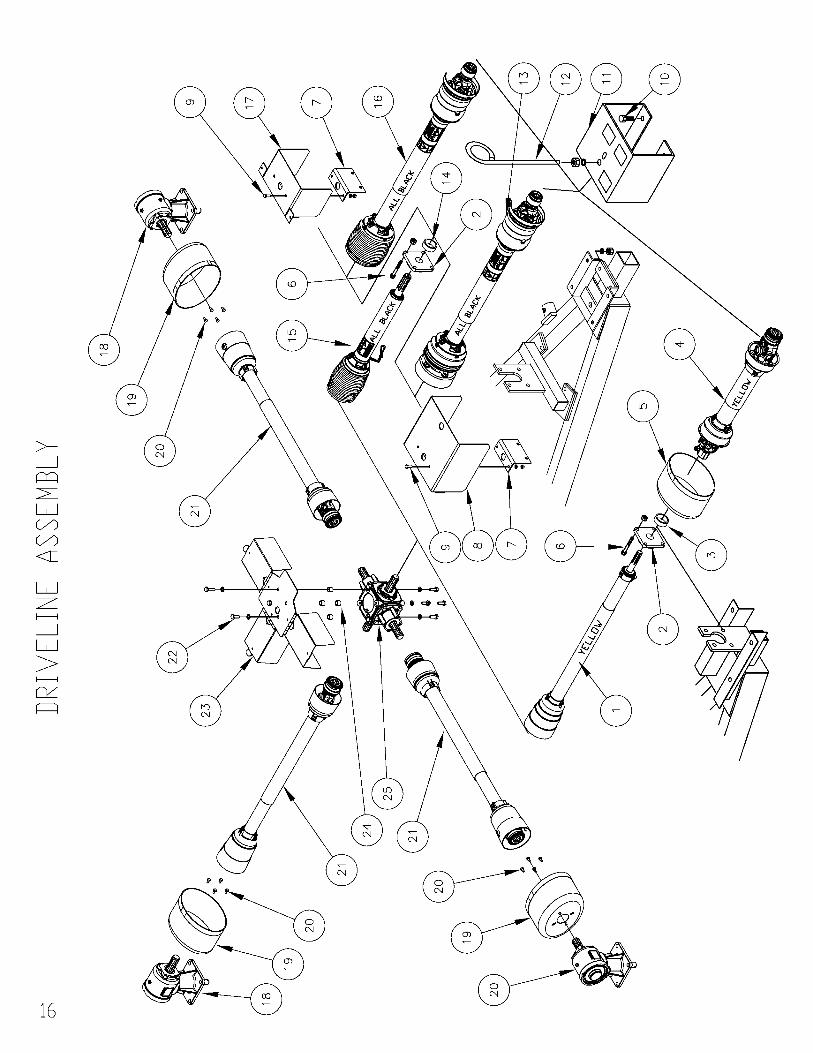

TD65 & 65-2 - DRIVE SYSTEM Rev. 2, JUNE 09
ITEM PART # DESCRIPTION 15.5' Serial No. 12' Serial No. QTY
1 521725 INTERMEDIATE PTO SHAFT A & C MODELS 9465276 & ABOVE 9465-2044 & ABOVE 1
521379 INTERMEDIATE PTO SHAFT REPL W/ 521725 9165101 TO 9465275 9365-2010 TO 9365-2043 1
2 521323 1" 3/8" HOUSED FLANGE BEARING 1
3 521789 PTO SHAFT SPACER - 9/16" A & C MODELS 1
4 521738 INPUT PTO SHAFT A & C MODELS 9465276 & ABOVE 9465-2044 & ABOVE 1
521386 INPUT PTO SHAFT REPL. W/ 521738 9165101 TO 9465275 9365-2010 TO 9365-2043 1
5 210062 COUNTER CONE INPUT C MODEL 1
6 O.L. 1/2" X 1 3/4" BOLT, LOCK, NUT 4
7 528439 INTERMEDIATE SHIELD BRACKET 1
8 528194 INTERMEDIATE SHIELD FOR CLUTCH D MODELS 1
9 3/8" X 1" HEX BOLT, LOCKWASHER, NUT 2
10 O.L. 1/2" X 1 1/4" BOLT, LOCK, NUT 4
11 522408 HYDRAULIC HOSE SUPPORT AND SHIELD 1
521711 HYDRAULIC HOSE SUPPORT AND SHIELD 9465276 TO 9865587 9465-2044 TO 9865-2422 1
521815 SHIELD EXTENSIONS WITH BOLTS 9765545 TO 9865587 9765-2342 TO 9865-2422 2
521711 HYDRAULIC HOSE SUPPORT 9365176 TO 9465275 9365-2010 TO 9365-2043 1
12 522413 HOSE GUIDE C/W HARDWARE 1
13 210250 INPUT PTO CV & CLUTCH 1
14 526013 PTO SHAFT SPACER - 0.400" B & D MODELS 1
15 210210 INTERMEDIATE PTO-w/OVERRUNNING B & D MODELS 1
16 210230 INPUT PTO C.V. B MODELS 1
17 600430 C.V. INTERMEDIATE SHIELD B MODELS 1
18 521012 DECK GEARBOX LF141A 3
19 210061 COUNTER CONE DECK C & D MODELS ONLY 3
20 O.L. M8 X 1.25 X 14MM C & D MODELS ONLY 12
21 521718 DECK PTO SHAFT 9465276 & ABOVE 9465-2044 & ABOVE 3
521389 DECK PTO SHAFT 9165101 TO 9465275 9365-2010 TO 9365-2043 3
22 521764 M12 X 30 8.8 METRIC BOLT, LOCK (8 PC/ KIT) 1 KIT
23 522463 4-WAY GEARBOX COVER 06651228 & ABOVE 0665-21167 & ABOVE 1
521195 GEARBOX COVER 9165101 TO 066512279365-2010 TO 0665-21166 1
24 521197 GEARBOX COVER SPACER 4
25 521497 4-WAY GEARBOX 9765545 & ABOVE 9765-2342 & ABOVE 1
521082 4-WAY GEARBOX 9165101 TO 9765544 9365-2010 TO 9765-2341 1OL - Obtain Locally AR - As Required QTY - Total Number Required for Complete Machine
17
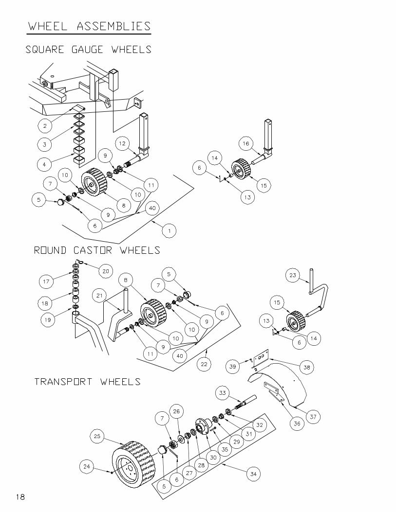

TD65 & 65-2 - WHEEL ASSEMBLY Rev. 2, JUNE 09
ITEM PART # DESCRIPTION 15.5' Serial No. 12' Serial No. QTY1 522320 SQUARE CASTOR COMP. +PARTS 9765545 & ABOVE 9765-2342 & ABOVE 42 521038 CLIP PIN - 2" SQUARE (5 PCS/KIT) 9765545 & ABOVE 9765-2342 & ABOVE 1 KIT3 521040 SPACER -SQ 3/8 X 2 1/2 (6 PCS/KIT) 9765545 & ABOVE 9765-2342 & ABOVE 2 KITS4 521039 SPACER - SQ 1" X 2 1/2 (6 PCS/KIT) 9765545 & ABOVE 9765-2342 & ABOVE 2 KITS5 521748 HUB CAP 9165101 & ABOVE 9265-2002 & ABOVE 106 521752 COTTERPIN (6 PCS/KIT) 9165101 & ABOVE 9265-2002 & ABOVE 2 KITS7 521747 HEX NUT - CASTELLATED (2 PCS/KIT) 9165101 & ABOVE 9265-2002 & ABOVE 6 KITS8 522317 TIRE/WHEEL.15/6X6 PRO-TURF 9765545 & ABOVE 9765-2342 & ABOVE 10
522315 RIM - 15X6.00 - TAPERED R BRG 9765545 & ABOVE 9765-2342 & ABOVE 10522316 TIRE - 15X6.00 KENDA/ PRO-TURF 9765545 & ABOVE 9765-2342 & ABOVE 10521848 TIRE - 15 X 6.00 KENDA 9465276 to 9765544 9465-2044 TO 9765-2341
521827 TIRE - 15 X 6.00 DURO 9465276 to 9765544 9465-2044 TO 9765-2341
9 521494 BEARING - TAPER ROLLER 9765545 & ABOVE 9765-2342 & ABOVE 2010 521744 BEARING RACE - OUTER 9765545 & ABOVE 9765-2342 & ABOVE 2011 521493 GREASE SEAL 9765545 & ABOVE 9765-2342 & ABOVE 1012 522314 SQUARE CASTOR (TAP. R. BRG) C/W ITEM 7 9765545 & ABOVE 9765-2342 & ABOVE 413 521320 SPACER WASHER - 1" (10 PCS/KIT) 9165101 - 9765544 9265-2002 TO 9765-2341 2 KITS14 521787 WHEEL BUSHINGS - GREY 1.375 0D 9465276 to 9765544 9265-2044 TO 9765-2341 10
521319 WHEEL BUSHING KIT 9165101 to 9465275 9265-2044 TO 9765-2341 20501319 BEARING 9165101 to 9465275 9265-2002 TO 9365-2043 20
15 521786 WHEEL ASSY 15 X 6.00 - KENDA 9465276 to 9765544 9465-2044 TO 9765-2341 10521788 WHEEL ASSY 15 X 6.00 - DURO 9465276 to 9765544 9465-2044 TO 9765-2341 10521772 RIM - FOR TD 1786 & TD 1788 9165101 to 9765544 9265-2044 TO 9765-2341
521318 TIRE AND RIM REPL. BY 521786 9165101 to 9465275 9265-2002 TO 9365-2043 1016 521352 CASTOR - SQUARE 9165101 - 9765544 9265-2002 TO 9765-2341 417 521022 SPACER - RD 3/8" X 1" (6 PCS/KIT) 9765545 & ABOVE 9765-2342 & ABOVE 3 KITS18 521021 SPACER - RD 1" X 1" (6 PCS/KIT) 9765545 & ABOVE 9765-2342 & ABOVE 3 KITS19 521320 SPACER WASHER KIT (10PCS/KIT) 1 KIT20 521038RD LYNCH PIN - 5/16" (4 PCS/KIT) 9765545 & ABOVE 9765-2342 & ABOVE 2 KITS21 522313 SWIVEL CASTOR (TAP. R BRG) C/W ITEM 7 9765545 & ABOVE 9765-2342 & ABOVE 622 522319 SWIVEL CASTOR RD COMPLETE 9765545 & ABOVE 9765-2342 & ABOVE 623 521317 CASTOR - 1" RD SWIVEL 9165101 to 9765544 9265-2002 TO 9765-2341 6
521833 CASTOR - 1"RD SWIVEL O/S (BLACK) 624 521327 WHEEL NUT (5 PCS/KIT) 9165101 & ABOVE 9265-2002 & ABOVE 2 KITS25 522305 TIRE & RIM -ASSY CARLISLE TIRE 9165101 & ABOVE 9265-2002 & ABOVE 2
522306 TIRE - 18X9.5 TURF FOR 522305 9165101 & ABOVE 9265-2002 & ABOVE 2521398 RIM - FOR 521028 & 521326 9165101 & ABOVE 9265-2002 & ABOVE 2
26 521746 WASHER (2 PCS/KIT) 9165101 & ABOVE 9265-2002 & ABOVE 1 KIT27 521745 BEARING - TAPER ROLLER 9165101 & ABOVE 9265-2002 & ABOVE 228 521744 BEARING RACE - OUTER 9165101 & ABOVE 9265-2002 & ABOVE 229 521743 BEARING RACE - INNER 9165101 & ABOVE 9265-2002 & ABOVE 230 521754 HUB #3500 - TRANSPORT 9165101 & ABOVE 9265-2002 & ABOVE 231 521742 BEARING - TAPER ROLLER 9165101 & ABOVE 9265-2002 & ABOVE 232 521741 GREASE SEAL 9165101 & ABOVE 9265-2002 & ABOVE 233 521807 SPINDLE - TD 65 WELD-ON FRAME 9165101 & ABOVE 9265-2002 & ABOVE 2
COMES WITH ITEMS 26 (1), 7 (1)34 521328 HUB ASSY 3500 LB. - 5 BOLT 9165101 & ABOVE 9265-2002 & ABOVE 2
35 521755 PRESS IN WHEEL STUD (5PCS/KIT) -36 528200 FENDER BRACKET R.H. 1
528198 FENDER BRACKET L.H. 137 524246 FENDER - TRANSPORT TIRE 238 528447 LIGHT BRACKET 239 O.L. 3/8" x 1" BOLT, LOCK & NUT 440 522420 BEARING KIT (ITEMS 9 (2), 10 (2), 11(1), 6 (1) ) 8
OL - Obtain Locally AR - As Required QTY - Total Number Required for Complete Machine 19
Early Machines

20
TD65 & 65-2 – DECK GEARBOX ASSEMBLY

TD65 & 65-2 - DECK GEARBOX ASSEMBLY Rev. 1, OCT 05
ITEM PART # DESCRIPTION SERIAL NUMBER QTY
1 521110 SNAP RING 1
2 521111 COVER PLATE 1
3 521112 BEARING - 6205 1
4 521113 KEY - 10 X 8 X 30 1
5 521114 SHAFT - 1 3/8" X 6 SPLINE 1
6 521115 GEAR 1
7 521116 BEARING - 6207 2
8 521117 CASING 1
9 521118 O - RING 1
10 521482 3/8" PIPE PLUG 2
11 521120 OIL SEAL - 35 X 52 X 7 1
12 521121 PINION SHAFT 1
13 521122 COTTERPIN - B5 X 50 1
14 521123 SHIM - 259.7504 AR (3PC/KIT) 2
15 521124 SPACER TUBE 1
16 521125 SNAP RING - 35 UNI 7435 (3PC/KIT) 1
17 521126 SNAP RING - 72 UNI 7437 (3PC/KIT) 1
18 521127 DOUBLE LIP SEAL - 35 X 72 X 10/8 1
19 521128 SNAP RING - SB72 1
20 521129 WASHER 25 X 44 X 4 (3PC/KIT) 1
21 521130 CASTALATED NUT M24 X 2 1
22 521390 KEY - 1/4" X 1/4" X 1 5/16" 1
23 521359 SHIM 1
24 521360 SHIM 259.7503 AR 1
25 521361 SPACER RING TAPERED 1
26 521362 BEARING TAPERED (30207A) 1
27 521491 SHIM - 248.7505 (KIT) AR 1
28 521491 SHIM - 248.7504 (KIT) AR 1
29 521491 SHIM - 248.7503 (KIT) AR 1
30 521366 SHIM - 259.7505 AR 1
521012 COMPLETE DECK GEARBOX 1OL - Obtain Locally AR - As Required QTY - Total Number Required for One Gearbox
21

22
4 – WAY GEARBOX ASSEMBLY

4-WAY GEARBOX ASSEMBLY Rev. 1, OCT 05
ITEM PART NO. DESCRIPTION SERIAL NUMBER QTY
1 521116 BEARING 6207 3
2 521794 SHIM KIT - 48.0 6
3 521127 OIL SEAL - 35 X 72 X 10/7 2
4 521481 STUB SHAFT - 1 3/8" SPLINE 2
5 521137 SNAP RING - 35 UNI 7435 4
6 521482 3/8" PIPE PLUG 2
7 521362 BEARING - 30207 3
8 521483 HOUSING 1
9 ITEM 20 BOLT - M12 X 40 - 10.9 2
10 ITEM 20 WASHER BLANK 2
11 521486 THRU SHAFT 1 3/8" X 1 3/8" 1
12 521120 OIL SEAL - 35 X 52 X 7 2
13 521487 GEAR Z18 M5 3
14 521488 BOLT - M12 X 25 - 8.8 KIT (6 PCS) 12
15 521489 OIL LEVEL DIPSTICK 1
16 521796 EXTENSION HOUSING 2
17 - GASKET (REPLACE W/SILICONE) 3
18 521797 COVER 1
19 521491 WASHER - SHIM (60 X 72) (3 PCS) 1
20 522426 BOLT KIT - ITEMS 9 (2) & 10 (2) 1
***** 521497 COMPLETE GEARBOX 1
OL - Obtain Locally AR - As Required QTY - Total Number Required for One Gearbox
23
24
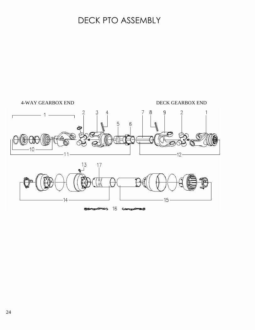
DECK PTO ASSEMBLY
4-WAY GEARBOX END DECK GEARBOX END

DECK PTO ASSEMBLY Rev. 1, OCT 05
ITEM PART # DESCRIPTION QTY.1 521778 QD. YOKE 1 3/8" - 6 SPLINE (CO2) 22 521779 CROSS & BEARING KIT 23 521780 OUTER TUBE YOKE 14 521781 ROLL PIN FOR OUTER TUBE 15 521451 "DANGER" LABEL FOR OUTER TUBE 16 521712 OUTER TUBE 17 521713 INNER TUBE 18 521782 ROLL PIN FOR INNER TUBE 19 521783 INNER TUBE YOKE 110 210017 COLLAR KIT (STEEL) 1
521727 COLLAR KIT (PLASTIC)11 521714 1/2 FEMALE SHAFT WITH SHIELDING 112 521715 1/2 MALE SHAFT WITH SHIELDING 113 521463 PLASTIC SHIELD BOLT (6PC/KIT) 614 521716 1/2 FEMALE SHIELD WITH LABEL 115 521717 1/2 MALE SHIELD 116 521467 SAFETY CHAIN 217 521455 "DANGER" LABEL FOR OUTER SHIELD 1
**** 521718 COMPLETE PTO SHAFT 3/ MACHQTY.- REPRESENTS TOTAL NUMBER REQUIRED
FOR ONE DECK PTO ASSEMBLY ONLY.
25

26
INTERMEDIATE PTO SHAFT A & C MODELS ONLY

INTERMEDIATE PTO SHAFT Rev. B, AUG 2013
ITEM PART # DESCRIPTION QTY.1 521719 SPLINED YOKE 12 521720 CROSS & BEARING KIT 13 521721 YOKE FOR OUTER TUBE 14 521722 ROLL PIN FOR OUTER TUBE 15 521451 "DANGER" LABEL FOR TUBE 16 521723 OUTER TUBE WITH SPLINED SHAFT 17 521463 PLASTIC SHIELD BOLT (6PC/KIT) 68 521467 SAFETY CHAIN 29 521724 COMPLETE SHIELD TYPE "P" WITH LABEL 110 521455 "DANGER" LABEL FOR OUTER SHIELD 1
**** 521725 COMPLETE PTO ASSEMBLY 1QTY.- REPRESENTS TOTAL NUMBER REQUIRED
FOR ONE INTERMEDIATE PTO ASSEMBLY ONLY.
See Service
Bulletin
521725
PTO Shaft;
Page 33
27

28
INPUT PTO SHAFT A & C MODELS ONLY
TRACTOR END MOWER END
20

INPUT PTO SHAFT Rev. 1, OCT 05
ITEM PART # DESCRIPTION QTY.1 521726 QD YOKE 1 3/8" - 6 SPLINE (CO2) 12 210017 COLLAR KIT - STEEL 1
521727 COLLAR KIT - PLASTIC3 521720 CROSS & BEARING KIT 24 521728 INNER TUBE YOKE 15 521729 BOLT M12 X 1.25 X 65 NUT 16 521730 INTERFERING BOLT CLAMP YOKE 17 521731 OUTER TUBE & YOKE WITH LABEL 18 521451 "DANGER" DECAL 110 521732 SPLINED SHAFT 111 521733 ROLL PIN FOR INNER TUBE 112 521734 1/2 FEMALE SHAFT WITH SHIELDING 113 521735 1/2 MALE SHAFT WITH SHIELDING 114 521463 PLASTIC SHIELD BOLT (6PC/KIT) 615 521736 1/2 FEMALE SHIELD WITH LABEL 116 521737 1/2 MALE SHIELD 117 521467 SAFETY CHAIN 218 521455 "DANGER" LABEL FOR OUTER SHIELD 119 521821 GREASE FITTING 220 521768 COMPLETE SHIELD KIT 1
**** 521738 COMPLETE PTO SHAFT 1QTY.- REPRESENTS TOTAL NUMBER REQUIRED
FOR ONE INPUT PTO ASSEMBLY ONLY.
29

INTERMEDIATE SHAFTB & D MODELS ONLY
30


INPUT PTO SHAFT – B MODELS TD 65: SERIAL #12651437B AND UP
TD65-2: SERIAL #1265-21361B AND UP
32

Service Bulletin: 521725 PTO Shaft
Part #521725, Intermediate Z50 shaft used on Pro-flex 120/TD65/TD65-2
For a period between 2003 and 2006, this PTO shaft was changed to one with a new shield. The shielding
seen in "Diagram 1A" was used before this, and was changed to shielding seen in "Diagram 2B" for this
period of time. See diagrams below on page.
If your Progressive Mower has an intermediate shaft with shielding as seen in "Diagram 2B", the parts
breakdown listing for the inner yoke found in your machine parts book is incorrect. Part #521721 (Yoke -
Outer Tube) must be changed to Part #521721.50 (Yoke - Inner Tube). The size of hole for mounting yoke
on the shaft is different in each application.
Diagram 1A Diagram 2B
INTERMEDIATE PTOSHAFT A & C MODELS ONLY
INTERMEDIATE PTO SHAFT
1A 2B
ITEM PN PN DESCRIPTION QTY.
1 521719 521719 SPLINED YOKE 1
2 521720 521720 CROSS & BEARING KIT 1
3 521721 521721.50 YOKE FOR OUTER TUBE 1
4 521722 521722 ROLL PIN FOR OUTER TUBE 1
5 521451 521451 "DANGER" LABEL FOR TUBE 1
6 521723 522050 OUTER TUBE WITH SPLINED SHAFT 1
7 521463 521463 PLASTIC SHIELD BOLT (6PC/KIT) 6
8 521467 521467 SAFETY CHAIN 2
9 521724 522060 COMPLETE SHIELD TYPE "P" WITH LABEL 1
10 521455 521455 "DANGER" LABEL FOR OUTER SHIELD 1
**** 521725 COMPLETED 1
HIGHLIGHTED PARTS ARE REQUIRED FOR SHAFT 2B SERVICE PARTS
QTY.- REPRESENTS TOTAL NUMBER REQUIRED
FOR ONE INTERMEDIATE PTO ASSEMBLY ONLY