operator’s manual - air techniques procedures outlined in this operator's manual. the a/t...
TRANSCRIPT

OPERATOR’S MANUAL
AUTOMAT I CF I LM PROCE S SOR

2
TABLE OF CONTENTS
Description Page
Congratulations . . . . . . . . . . . . . . . . . . . . . . . . . . . . . . . . . . . . . . . . . . . . . . . . . . . . . .2
Air Techniques Warranty . . . . . . . . . . . . . . . . . . . . . . . . . . . . . . . . . . . . . . . . . . . . . . . .2
On-Line Warranty Registration . . . . . . . . . . . . . . . . . . . . . . . . . . . . . . . . . . . . . . . . . . . .2
External Key Parts Identification . . . . . . . . . . . . . . . . . . . . . . . . . . . . . . . . . . . . . . . . . . .4
Internal Key Parts Identification . . . . . . . . . . . . . . . . . . . . . . . . . . . . . . . . . . . . . . . . . . .5
Operator Controls . . . . . . . . . . . . . . . . . . . . . . . . . . . . . . . . . . . . . . . . . . . . . . . . . . . .6
Know Your Processor . . . . . . . . . . . . . . . . . . . . . . . . . . . . . . . . . . . . . . . . . . . . . . . . . . .7
Daily Operation . . . . . . . . . . . . . . . . . . . . . . . . . . . . . . . . . . . . . . . . . . . . . . . . . . . . . .8
Processed Film Testing . . . . . . . . . . . . . . . . . . . . . . . . . . . . . . . . . . . . . . . . . . . . . . . . .10
Avoiding Chemistry Contamination . . . . . . . . . . . . . . . . . . . . . . . . . . . . . . . . . . . . . . . .11
Weekly Maintenance . . . . . . . . . . . . . . . . . . . . . . . . . . . . . . . . . . . . . . . . . . . . . . . . . .12
Monthly Maintenance . . . . . . . . . . . . . . . . . . . . . . . . . . . . . . . . . . . . . . . . . . . . . . . . .13
Quarterly Maintenance . . . . . . . . . . . . . . . . . . . . . . . . . . . . . . . . . . . . . . . . . . . . . . . .15
Specifications . . . . . . . . . . . . . . . . . . . . . . . . . . . . . . . . . . . . . . . . . . . . . . . . . . . . . . .17
Plumbing Connections - Option 1 . . . . . . . . . . . . . . . . . . . . . . . . . . . . . . . . . . . . . . . .18
Plumbing Connections - Option 2 . . . . . . . . . . . . . . . . . . . . . . . . . . . . . . . . . . . . . . . .19
Trouble Shooting . . . . . . . . . . . . . . . . . . . . . . . . . . . . . . . . . . . . . . . . . . . . . . . . . . . . .20
Optional Accessories . . . . . . . . . . . . . . . . . . . . . . . . . . . . . . . . . . . . . . . . . . . . . . . . . .29
A/T 2000 XR, PN 45009 (with Water Recirculation) . . . . . . . . . . . . . . . . . . . . . . . . . . . .30

3
CONGRATULATIONS
You have purchased a new, easy to use, easy to maintain A/T 2000 XR Automatic Dental Film Processor!Your new processor is manufactured by Air Techniques, Inc., manufacturer of dental equipment since1962. All Air Techniques products are designed to meet the exacting quality standards of modern den-tistry.A/T 2000 XR processes all intraoral, occlusal, TMJ, panoramic, cephalometric, and duplicating film sizes.The operator can choose between a “quick-look” 2½ minute ENDO SPEED cycle or a full 5½ minutesNORMAL SPEED cycle. The active mode is clearly indicated with an illuminated arrow. Simply select the speed and insert a film into the film inlet and the processing cycle automatically starts.When processing is complete, the film exits into the film receptacle tray, and the A/T 2000 XR automat-ically returns to stand-by.A/T 2000 XR takes the guesswork out of chemistry replenishment - a micro-computer counts film andautomatically replenishes chemistry proportional to film load for the best processing results. Your newA/T 2000 XR is also designed with the environment in mind - used chemistry is easily captured for dis-posal in accordance with local codes. For locations where local codes require or the user opts for waterconservation, Air Techniques offers an A/T 2000 XR Model 45009 with built-in water recirculation.A/T 2000 XR incorporates modular components for easy maintenance and service. To make sure yourfilm processor gives you the highest level of service, please review and follow the operation and mainte-nance procedures outlined in this OPERATOR'S MANUAL.
The A/T 2000 XR Automatic Dental Film Processor is warranted to be free from defects in material andworkmanship from the date of installation for a period of twenty-four (24) months.
All part and component returns and replacement equipment under warranty require a Return MaterialsAuthorization (RMA). Warranty returns must be received within three months of the RMA issue date. RMAsexpire three months after issue date. Items returned without an RMA, or included with other products forwhich an RMA has been issued, may be returned to the customer at the discretion of Air Techniques, Inc.
Any item returned under warranty will be repaired or replaced at our option at no charge provided thatour inspection shall indicate it to have been defective. Air Techniques, Inc. is not liable for indirect or con-sequential damages or loss of any nature in connection with this equipment. Dealer labor, shipping andhandling charges are not covered by this warranty.
Warranty credit will not be applied to product returns that exhibit damage due to shipping, misuse, care-less handling or repairs by unauthorized personnel. Credit, or partial credit, will not be issued until prod-ucts/parts have been received and assessed. Warranty is void if product is installed or serviced by any-one other than an authorized Air Techniques' dealer or service personnel.
This warranty is in lieu of all other warranties expressed or implied. No representative or person is author-ized to assume for us any liability in connection with the sale of our equipment.
WARRANTY
ON-LINE WARRANTY REGISTRATIONQuickly and easily register your new A/T 2000 XR on-line. Just have your product model number andserial number available. Then go to the Air Techniques website, www.airtechniques.com, click thewarranty registration link and complete the registration form. This on-line registration ensures a recordfor the warranty period and helps Air Techniques keep you informed of product updates and other valu-able information.

4
EXTERNAL KEY PARTS IDENTIFICATION
IECCONNECTOR(AT REAR
FILM INLET WITHACTIVATINGSHUTTER
FILMRECEPTACLE TRAY
POWER SWITCH
ADJUSTSET-TEMP
DIVIDERS
OPERATOR’SCONTROLS(SEE FIG.1)
LEVELINGFOOT
REPLENISHMENT PUMPAND AGITATOR
BUBBLE LEVEL
LEVELINGFOOT
LEVELINGBASE

5
INTERNAL KEY PARTS IDENTIFICATION
PROCESSORCOVER
ELECTRICALCABLEPROCESSOR
COVER
ACTIVATINGSHUTTER
DEVELOPERRACK (BLACK)
FIXER RACK(RED)
WASH/DRY RACK
DEVELOPERDRAIN TUBE(BLACK)
FIXER DRAINTUBE (RED)
WASH/DRYDRAIN TUBE
FIXERTANK
RUBBERWASHER
FILL LINE
DEVELOPERTANK
FILMINLET
WASHTANK
BUBBLELEVEL
LEVELINGLEVELINGBASE
WORMDRIVESHAFT
DEVELOPERRACK LATCH
SAFETY SWITCH ACTIVATOR
THERMISTOR
FIXER RACKLATCH
WASH/DRYRACK
LATCHES
GEARCOVER
WEEP HOLE
INNER BAFFLE
OUTER BAFFLE
BAFFLE PLATES
ON LEFT END BOTTOM OFBAFFLE MUST PASS BELOWRAISED BOSS ON SIDE PLATE
RAISED BOSS

OPERATOR CONTROLS
6
Before processing films, we recommend familiarizingyourself with the operator controls (Fig. 1):
INDICATOR LIGHTS
POWERIlluminates when the POWER switch (located on top) is in the ON position.
READYIlluminates when chemistry has reached SET-TEMPoperating temperature (factory Pre-set at 82°F,28°C). When READY illuminates, chemistry is atthe proper temperature to process films.
PROCESSINGIlluminates when a film has been inserted and isbeing transported through the process cycle.
PROCESSING flashes regularly when the film is feeding past the film inlet shutter and for 5 secondsafter the shutter closes. When processing extraoral films, wait until PROCESSING stops flashingbefore inserting the next film to prevent films from overlapping. When the processor is in a stand-bymode, ready to accept films for processing, PROCESSING will not be illuminated. When theCLEANING MODE is selected, the PROCESSING light flashes (short-long...).
KEY PADS
q ENDO SPEED: The arrow indicator to the left of the keypad flashes when the A/T 2000 XR is inthe ENDO SPEED mode. Film is processed in 2½ minutes.
q NORMAL SPEED: The arrow indicator to the left of the keypad illuminates steady when the A/T2000 XR is in the NORMAL SPEED mode. Film is processed in 5½ minutes.
q DISPLAY SET-TEMP: The selected chemistry set point temperature flashes on the TEMPERATUREdisplay when the keypad is pressed and held. Otherwise, the TEMPERATURE display indicatesactual chemistry temperature. If the keypad is pressed and the display does not flash a differ-ent value, the set point and actual chemistry temperatures are the same and READY is illumi-nated. If this is not the case, see TROUBLE SHOOTING or contact your authorized AirTechniques Dealer. The SET-TEMP is factory pre-set at 82°F (28°C).
q CLEANING MODE: Use this keypad only during cleaning procedures. CLEANING MODE acti-vates an extended 10 minute process cycle. Processing indicator light flashes (short-long...)when in this mode.

7
KNOW YOUR PROCESSOR
The A/T 2000 XR is designed with modular parts that can be removed and reinstalled with ease, mak-ing maintenance relatively effortless. Get to know the inside of your processor before processing filmand before following the recommended procedures in the Maintenance section of this manual.
1. The A/T 2000 XR uses a standard dedicated 115V outlet.
2. Rack Assembly end plates, latches, and drain tubes are color codedfor easy identification: Developer is black and Fixer is red.
3. The wash tank drain tube is different from the other drain tubes. Ithas a “weep” hole to prevent algae growth in the wash tank. Whencleaning the Wash tank with Formula 2000, it is necessary to coverthe drain tube weep hole with a washer that comes with the proces-sor. This washer is the same as the ones on the Developer and Fixerdrain tubes. After cleaning, this washer MUST be removed and saved for reuse. (Fig. 2 & 3)
5. To remove a rack assembly, first slide the latches to the open position. Be sure to slide latchesback into the lock position after reinstalling the rack assemblies.
6. The Wash / Dry Rack Assembly comes with two baffle platesinstalled: an inner baffle and an outer baffle. If these slideout accidentally during cleaning, be sure to reinstall them inexactly the same way. See the illustration in Internal Key PartsIdentification, pg. 5. The inner baffle is installed first. Onthe left end, the bottom of the outer baffle must pass belowraised boss on side plate.
7. Make sure your processor is level. Check the bubble levelon the leveling base at the front of the processor. The bub-ble should be in the middle. If it is not, level the processorby adjusting the leveling feet. The processor should be on asflat a surface as possible.
8. With rack assemblies removed, fill the tanks with chemistryto the fill line only. (Fig. 4)
9. Replace replenishment chemistry bottles every two weeks orwhen there is 1" or less left in the bottom of the bottles,whichever comes first. Do not mix chemistry brands. Do notuse the 1" of chemistry left in the bottles.
10.DO NOT, UNDER ANY CIRCUMSTANCES, USE SOAP,DETERGENTS OR OVER-THE-COUNTER CLEANSERS TOCLEAN RACK ASSEMBLIES OR TANKS. Use only approvedcleaners designed for cleaning X-ray film processors.
WEEP HOLE
NOTES:
1.To prevent damage always raise front first when lifting cover.
2.If the cover is opened during processing, the safety switch opens and the drive motor stops.That is a safety feature of the A/T 2000 XR.

8
DAILY OPERATION
BEFORE PROCESSING FILM
CAUTION: Developer and Fixer tanks must contain chemistry before processing film. SeeMonthly Maintenance for chemistry filling procedure.
1. CHECK FLUID LEVELS IN THE CHEMISTRY REPLENISHMENT BOTTLES. q Replace replenishment chemistry bottles every two weeks or when there is 1" or less left in
the bottom of the bottles, whichever comes first. Do not mix chemistry brands. Do not usethe last 1" of chemistry left in the bottles.
2. TURN ON MAIN WATER SUPPLY.
3. TURN ON POWER SWITCHq Automatically, approximately 4 1/4 oz. (125 ml) of chemistry is pumped into each of the
developer and fixer tanks to compensate for oxidation.q POWER, TEMPERATURE display, and the NORMAL SPEED lights illuminate.q READY light illuminates when chemistry reaches SET-TEMP (factory set at 82°F/28°C) in
approximately 15 to 35 minutes, depending on initial chemistry temperature.
4. READY TO PROCESSq When the READY light is on, A/T 2000 XR is at the factory SET-TEMP of 82°F (28°C) and
ready to process film.
5. INSERT CLEANING FILMq Insert a new cleaning film after the READY light illuminates. q The cleaning film picks up condensate and/or dried chemistry deposits which may be onthe rollers. Use a new cleaning film every time to avoid contaminating the chemistry. (A previ-
ously used cleaning film has residual fixer on it which will contaminate the developer.)q After the cleaning film exits, the processor will return to stand-by automatically.
IMPORTANT: If the processor is idle (no films processed) for more than 2 hours, insert a newcleaning film before resuming processing.
PROCESSING FILM
1. SELECT PROCESS MODE
ENDO SPEEDq For non-archival “quick-look” 2½ min. #2 intraoral film processing only, press ENDO
SPEED when the processor is in the stand-by mode (when PROCESSING light is not illumi-nated). ENDO SPEED is for intraoral films only and must not be used with panoramic orcephalometric films.
q The indicator light next to ENDO SPEED flashes as a reminder that the processor is in theENDO SPEED mode.
q Insert ONE #2 film only, as described on pg. 9. Wait until the film exits and unit stops pro-cessing before inserting the next endo film. If you do not wait, the insertion of another filmwill override the ENDO SPEED mode and the processor will automatically switch to NOR-MAL SPEED.
q When the endo cycle finishes, the processor automatically returns to stand-by and NORMAL

9
DAILY OPERATION
PROCESSING FILM (continued)
NORMAL SPEEDq For archival quality films, 5½ min. processing of all size films, use NORMAL SPEED mode. If
the processor is not in this mode, press NORMAL SPEED. NOTE: If an ENDO film is pro-cessing, its exit will be delayed if NORMAL SPEED is pressed.
q Insert film as described below.
2. INSERT FILM
Follow the film manufacturer’s exposure guidelines to obtain quality radiographs.
If radiographs processed at NORMAL SPEED and 82°F (28°C) are too dark, reduce the x-rayexposure/time setting.q Insert a film in the film inlet: processing starts automatically. A/T 2000 XR has 6 tracks for
intra-oral film. Feed film in lengthwise, into alternating tracks to prevent overlapping. Forexample, insert 1 film each into tracks 1,3,5: then 1 film each into tracks 2,4,6. (Tracks areclearly marked on the film inlet.)
q Feed in large films lengthwise and straight. Be sure to wait until the PROCESSING light stopsflashing, approximately 5 sec. after the film is in the processor, before inserting the next film.Wait approximately 20 sec. before turning on the lights or opening the darkroom door.
q When loading intraoral film, always make sure the marker point enters last.
BE SURE TO STRAIGHTEN BENT FILMS BEFORE INSERTING IN FILM INLET.
3. CLEANING MODEq ONLY push CLEANING MODE to activate processing when executing recommended main-
tenance procedures (SEE MAINTENANCE).
4. AT END OF THE DAYq Turn off the POWER switch and the external water supply valve. (If you have an A/T 2000 XR
with water recirculation, refer to pg. 30.)
NOTE: When processing film in ENDO SPEED, it is possible to change to NORMALSPEED before the film exits. But when processing film in NORMAL SPEED, itis not possible to change to ENDO SPEED until the film has exited and theprocessing light has extinguished. This feature is designed to protectarchival quality films.

10
PROCESSED FILM TESTING
PROCESSED FILM TESTING
1. TESTING PROCESSED FILM QUALITYq Turn on the POWER switch and wait for the READY light to illuminate.q Insert a new cleaning film. Run it through at NORMAL SPEED.q Insert an unexposed film and process at NORMAL SPEED. The processed film should be
completely clear if the film was handled under darkroom conditions with the lights off.q Expose a film to room light for 3-5 sec. and then process at NORMAL SPEED. The
processed film should be completely black. If the results differ from the above, consultTROUBLE SHOOTING, pages. 20-28 for suggestions on how to correct.
2. TESTING PROCESSED FILM CONSISTENCYq At NORMAL SPEED process a double film packet that has been exposed as part of a regular
X-ray examination.q Mount one of these properly processed films in the corner of a view box, and retain it as an
index film.q Periodically, place a film next to this index film for comparison. When comparing, make sure
the film was processed at NORMAL SPEED and has been exposed using the identical tech-nique factors as the index film. Compare the density and clarity of the two films.
NOTE: Consult TROUBLE SHOOTING, pages 20 through28 in this manual for suggestionson how to correct film density and clarity.

11
AVOID CHEMISTRY CONTAMINATION
Contamination of developer chemistry is one of the most common problems associated with x-ray film
processors. The source of contamination must be identified to prevent this problem from happeningagain. Once contaminated developer is diagnosed, tanks and rack assemblies must be cleaned withFormula 2000, (Part Number: 43965). See Quarterly Cleaning, pages. 15 & 16 for proper cleaningprocedure.
How To Diagnose Contaminated Developer One or more of these symptoms indicates contamination:
q Ammonia smellq Dark or black developerq Black deposits on bottom of developer tankq Gray stains on white gears on side of developer rackq Black streaks or smudges on filmsq Poor film density (blacks are only dark gray)q Poor film clarity
Sources of Contaminated DeveloperOne or more of these actions can cause contamination:1. Splashing a drop of fixer into Developer tank when filling Fixer tank.2. Dripping a drop of fixer into the Developer tank when removing racks for cleaning.3. Washing both Developer and Fixer tanks with the same sponge or same brush. (Use separate
sponges or brushes for each tank.)4. Failing to thoroughly rinse off Spray 2000 when cleaning rack assemblies.5. Use of soap, detergents, etc. to clean racks or tanks. Only use recommended cleaner.6. Use of Spray 2000 to clean the Developer tank. Only use on racks since it is very difficult to thor-
oughly rinse Spray 2000 out of tanks, thereby contaminating new chemistry.7. Running of endo films back through the processor. Endo films are never properly washed and
contain enough fixer residue to contaminate the Developer tank.8. Use of a cleaning film more than once or use of one that looks dirty - do not reuse cleaning film.9. Scrubbing cleaning film with soap and water so it can be reused . - do not reuse cleaning film.10.Running of cleaning film at ENDO speed, then reusing cleaning film - do not reuse cleaning film.11.Running of cleaning film with wash water turned OFF, then reusing cleaning film - do not reuse
cleaning film.12.Failing to thoroughly rinse developer tank after using Formula 2000, including forgetting to run
developer agitator while rinsing.13.Failing to purge replenishment lines after using Formula 2000.14.Incorrectly installed drain lines.15.Accidentally bumping processor, causing fixer to spill over into the Developer tank.16.Interchanging replenishment bottles, connecting fixer to developer and developer to fixer. (Use 4
gallons of warm water to clean out pumps and lines).17.Mixing different brands of chemistry together. Example: Brand A in the tanks, Brand B in replen-
ishment bottles.
NOTE: IF CHEMISTRY IS Contaminated, FOLLOW CLEANING PROCEDURE DETAILEDIN QUARTERLY CLEANING PAGES. 15 & 16.

12
WEEKLY MAINTENANCE
Cleaning your A/T 2000 XR on a weekly, monthly, and quarterly basis is critical in maintainingquality processor performance. We recommend the maintenance procedure outlined belowusing Spray 2000 and Formula 2000 cleansers especially Formulated for the A/T 2000 XR. Thissuggested maintenance schedule may have to be modified if your processor requires more fre-quent cleaning.
WEEKLY . . . Clean Rack Assemblies
CAUTION: Turn POWER switch OFF before removing the cover, the rack assembly ordisconnecting any electrical cables.
1. SLIDE THE LATCHES OPENq Unplug the processor cover electrical cable from the processor base and remove cover.
Set aside.q Slide the latches open.q Lift each rack assembly straight up, and move it directly to the side to avoid dripping
chemistry into the adjacent tanks.
NOTE: Dripping just a few drops of Fixer into the Developer tank will contaminate theDeveloper and result in poor film quality.
2. CLEAN RACK ASSEMBLIES (Do not soak overnight)q Place the rack assemblies in a large sink; thoroughly moisten with Spray 2000 or water.q Clean with a soft brush or use a sponge for each rack and warm running water to clean
rollers and gears. Be sure to rotate gears while cleaning rollers.q Rinse each rack assembly thoroughly and allow to dry.
3. REINSTALL RACK ASSEMBLIESq Slowly lower each rack into its tank. Match color-coded end plates to color-coded latches. q Do not splash fixer into Developer tank when installing Fixer rack.q Close all the latches. q Replace the cover and reattach the electrical cable to the base.
4. PROCESS A CLEANING FILMq Turn on the power.q Always process a new cleaning film after cleaning the rack assemblies (at normal speed,
after READY light illuminates).
NOTE: When cleaning the gears, a soft brush can be used to loosen and remove stub-born deposits. Do not use soap, detergents, or abrasive cleaners. Be sure to usea separate brush or sponge for each rack. Color coded sponges are suppliedwith each case of Air Techniques Developer & Fixer.

13
MONTHLY MAINTENANCE
MONTHLY . . . Change chemistry
If the bottom of the Developer tank is coated with black residue and/or the white gears on the sideof the Developer rack are stained grey or black, the developer has been contaminated. TheDeveloper tank and rack must be cleaned with Formula 2000 (see Quarterly Maintenance pages.15 & 16). See Avoiding Chemistry Contamination, pg. 11 and TROUBLE SHOOTING, pages.20-28 for causes and solutions.
1. REMOVE COVERq Disconnect the cover electrical cable from the processor base and remove the cover.
2. REMOVE RACK ASSEMBLIESq Remove all the rack assemblies, taking care not to drip fixer into the Developer tank.
3. DRAIN AND CLEAN TANKS
CAUTION: Be sure to dispose of any chemistry and chemistry ladenwater in accordance with local codes.
q Unscrew and remove the Fixer, Developer and Wash tank draintubes and completely drain the tanks. Replace the color codeddrain tubes, fill all three tanks with warm water, then drain. Repeatthis drain / fill / drain sequence 4 times all together.
q Locate the chemistry agitators in the bottom of the Fixer andDeveloper tanks. These agitators mix the chemistry in the tanks,preventing crystallization and optimizing chemistry performance. Tomake sure that the agitators move freely and to prevent the agitatorscrews from seizing, the agitators must be disassembled and cleaned regularly:
- Remove the thumb screw, plastic cap, magnet, washer and ceramic post.
- Clean all the parts with Spray 2000 and warm water. Rinse thoroughly and set aside.q While the chemistry agitators are disassembled, wipe down the tanks with sponges to
eliminate any chemistry residue. Use a separate sponge for each tank. Reassemble thechemistry agitators as shown in Fig. 5. Refill all tanks with warm water to the fill line.Reinstall the drain tubes.Fill all the tanks with warm water to the fill line.
4. FLUSH AGITATORSq Replace the processor cover (reconnect the cover electrical cable to the base), press and
hold CLEANING MODE and turn ON the power at the same time. When CLEANINGMODE is pressed, the agitators rotate and are rinsed by the warm water in the tanks.CLEANING MODE will prevent initial replenishment from occurring.
q Shut off the power after two minutes.q Disconnect the cover electrical cable from the base, remove the processor cover and
drain all three tanks. q Thoroughly wipe up any standing water with a clean paper towel or separate sponges. Any
water remaining in the tanks will dilute the chemistry. Reinstall the color-coded drain tubes.
CAUTION: Do not turn on power when the Developer and Fixer tanks areempty. Turn POWER switch OFF before removing the cover, therack assemblies, or disconnecting any electrical cables.

14
MONTHLY MAINTENANCE
5. CLEAN RACK ASSEMBLIESq Place rack assemblies in a large sink; thoroughly moisten with Spray 2000 or water,
then clean with a soft brush or sponge under warm running water.
q Rotate the gears and rollers while cleaning.q Be sure to use a separate soft brush or sponge for each rack. Color-coded sponges are
supplied with each case of Air Techniques Developer and Fixer.q Thoroughly rinse the racks and drain.
6. REFILL THE TANKS WITH CHEMISTRYq Fill the Fixer tank with fixer to the fill line. POUR SLOWLY! Do not splash or splatter. If
fixer is splashed into the Developer tank, wipe up completely with clean moistened towelor sponge.
q Fill the Developer tank with developer to the fill line. POUR SLOWLY! Add 2 oz. ofStarter.
7. REINSTALL RACK ASSEMBLIESq Slowly lower each rack into its tank, matching color-coded rack end plates to color-
coded latches and color coded drain tubes. Do not splash fixer into Developer tankwhen installing Fixer rack.
q Close all latches. Replace the cover and reconnect the cover electrical cable to theprocessor base.
8. PROCESS A CLEANING FILMq Turn ON the power.q Process a new cleaning film (at NORMAL SPEED, after READY light illuminates).q If chemistry or water splashes onto the film inlet shelf, wipe it up with a paper towel or
sponge.
NOTE: When cleaning rack assemblies, only use a soft bristle brush. A hard bristlebrush may score and scratch the rollers, leaving undesirable markings on thefilm. Do not use soap, detergents or abrasive cleaners.

15
QUARTERLY MAINTENANCE
QUARTERLY....Clean with Formula 2000
Clean your A/T 2000 XR processor with Formula 2000 Tank and Transport Cleanser every threemonths or whenever a black residue is evident on racks and/or tank. Formula 2000 (Part Number:43945) is available from your authorized Air Techniques Dealer.
1. TURN OFF POWER AND CLOSE WATER SUPPLY VALVEq Unplug the cover electrical cable from the processor base and remove the cover.
2. REMOVE ALL RACK ASSEMBLIES, RINSE AND SET ASIDE.
3. PREPARE PROCESSOR FOR CLEANING WITH FORMULA 2000q Unscrew and remove the Fixer, Developer and Wash tank drain tubes and completely
drain the tanks. Replace the color coded drain tubes, fill all three tanks with warmwater, then drain. Repeat this drain /fill /drain sequence 4 times all together.
q Wash tank
- If the Wash tank is not dirty or shows no evidence of contamination, reinstall the draintube and the Wash/Dry rack assembly.
- If the Wash tank is dirty or contaminated, cleaning with Formula 2000 is recommended.
Follow the same procedure as for the Developer tank, as described below, but it is neces-sary to block the drain tube weep hole with the special washer that is included with theprocessor. This washer prevents the tank from draining during cleaning (See Fig. 2). Whencleaning is completed, remember to remove the washer and save it for reuse.
q Fixer tank
- Install the Fixer tank drain tube, fill the Fixer tank with water, install the rack assembly.
- NEVER USE FORMULA 2000 IN THE FIXER TANK.q Developer tank
- Install the drain tube.
- Pour Formula 2000, Component 1, into the empty Developer tank.
- Fill the tank with cold water to the fill line.
- Cut open the Formula 2000 Component 2 powder packet, and sprinkle the contentsevenly over the tank. The effervescent action of Formula 2000 will begin as soon asComponent 2 is added. Some odor and vapor will be evident. Do this in a well ventilatedarea.
- Before placing the Developer rack in the tank, dip each end into the Formula 2000 solu-tion to dissolve any build-up and deposits on the gears and end plates.
q Replace the cover and reconnect the cover electrical cord to the processor base.
NOTE: Opening the cover during the processing cycle or during a CLEANING MODEcycle opens the safety switch and stops only the drive motor. The rollers anddrive gears stop rotating. This is a safety feature of the A/T 2000 XR.
CAUTION: Turn POWER switch OFF before removing the cover, the rackassemblies, or disconnecting any electrical cables. USE FOR-MULA 2000 IN A WELL VENTILATED AREA.

16
QUARTERLY MAINTENANCE
4. RUN PROCESSORq Press and hold CLEANING MODE and turn ON the power at the same time to activate
the 10 minute cleaning cycle. If deeper cleaning is required, press CLEANING MODEagain when the first cycle ends.
q Occasionally, while the processor is running, lift the cover and wipe the rollers and drivegears of each rack above the solution with a sponge to loosen any remaining deposits.Use a separate sponge for each tank. Close the cover so that rollers can resume rotat-ing in the cleaning solution.
5. CLEAN THE RACKSq Turn off the POWER switch, disconnect the cover electrical cable from the processor
base and remove the cover.q Remove the rack assemblies and place them in a large sink. Clean with a soft brush
or sponge under warm water. Rotate the gears and rollers while cleaning. Remove alltraces of Formula 2000 to avoid contaminating the fresh chemistry!
6. PRELIMINARY RINSE (flushing Formula 2000)q Make sure the POWER switch is off.q Remove the drain tubes and drain the tanks. Dispose of the cleaning solution in accor-
dance with local codes. Replace the drain tubes.q Fill the tanks with water, replace the cover and reconnect the cover electrical cable.
Press and hold CLEANING MODE and turn ON the power at the same time to run theprocessor for a few minutes, then lift the cover and drain.
q Be sure to remove the washer covering the weep hole in the Wash tank drain tube ifyou cleaned the Wash tank. Save the washer for reuse.
7. FINAL RINSEq Reinstall the drain tubes and fill the tanks with water.q Turn on the processor water supply. Turn on the POWER switch. The replenisher pumps
will run and purge any Formula 2000 that may have gotten in the replenishment lines.Turn OFF the POWER switch after 2 minutes. Lift the cover and drain the tanks.
q Drain, refill the Developer and Fixer tanks with water, and drain again.q Wipe the Developer and Fixer tanks dry with a paper towel. Use a separate towel for
each tank.q Fill the Fixer and Developer tanks with chemistry, reinstall the rack assemblies and
process a new cleaning film. (See MONTHLY MAINTENANCE #6, 7, 8 on pg. 14.)
CAUTION: Do not turn on the power when the Developer and Fixer tanksare empty.

17
SPECIFICATIONS
ELECTRICAL 115V, 60Hz, 8 Amp. Use a 15 Amp, 3 prong, grounded outlet. A separate dedicated 15 Amp line is recommended.WATER FLOW ½ gallon per minute (while processing film). Water softeners should not be
used.WATER PRESSURE 80 psi maximum/30 psi minimum. If water pressure is high, above 60 psi,
install pressure regulator available on PN 45550. Water source must have amanual shut-off near processor.
WATER CONNECTION Valved 3/4" male straight pipe or standard male garden hose fitting at rearof processor.
WATER BACKFLOW An air break is not required because the processor has a 1" air gap PREVENTION between water supply inlet and top of operating water level in wash tank.WATER TEMP 55°F (13°C) to 80°F (27°C). A mixing valve is not required if water tempera-
ture is within this range.DRAIN 1½” vertical PVC standpipe, open at top, connected to 1½” PVC trap. DO
NOT DRAIN INTO COPPER OR BRASS. The top of the standpipe must be 6"below the bottom of the countertop.
DIMENSIONS 18"H x 15"W x 25"D with leveling base. (See below for required clearances.)WEIGHT 90 lbs. with water and chemistry (75 lbs. empty) VENTILATION Room air temperature must be below 80°F (27°C) during processing.
Because heat is generated during processing, adequate ventilation isrequired to maintain darkroom temperature.
CHEMISTRY REPLENISHMENT (approximate)Initial Power On 4-1/4 ounces in 90 secondsEvery 13-3/4 inch Linear film 1-2/3 ounces in 35 seconds
FILM FEED AND PROCESSING TIMES*MODE FILM SIZE FEED TIME**
"Leading Edge in" to "Trailing Edge in"Min. (Sec.)
PROCESS TIME"Trailing Edge in" to"Trailing Edge out"Min. (Sec)
TOTAL TIME"Leading Edge in" to"Trailing Edge in"Min. (Sec)
ENDO #2 (Intraoral) 1/8 (7) 2 ½ (150) 2 5/8 (157)
ENDO (CUL) #2 (Intraoral) 1/8 (7) 2 1/3 (140) 2 ½ (147)
NORMAL #2 (Intraoral) 1/4 (15) 5 ½ (330) 5 3/4 (345)
10" (Ceph) 1 2/3 (100) 5 ½ (330) 7 1/6 (430)
12" (Pan) 2 (120) 5 ½ (330) 7 1/2 (450)
*Times are approximate. ** Time varies slightly with other size intraoral films, depending on film length.***Time measurement from shutter closing to drive motor shut-off.
Height
16”
2”
22”Depth 25”
Width 15”23-1/2”
CYCLE***
RUN
TIME Min. (Sec)
3:06 (186)
3:06 (186)
6:30 (390)
DIMENSIONS

18
PLUMBING CONNECTIONS - OPTION 1

19
PLUMBING CONNECTIONS - OPTION 2

20
TROUBLESHOOTING
PROBLEM CAUSE SOLUTION
1. Processor totally inactive.No lights when POWERswitch is turned on.
A. Line cable is not plugged into wall outlet orIEC connector at the back of the processor.
B. Cover electrical cable is not connected tobase receptacle..
C. No power supplied to Processor, 115V outlet.
D. Possible blown fuse.
A. With POWER switch OFF, plug line cable intooutlet and check line cable connection at IECconnector.
B. Plug cover electrical cable into base
receptacle.C. If still no power, try a different outlet. If the
processor still does not work, call your author-ized Air Techniques dealer for service.
D. Locate fuse next to power cable in back ofmachine. Replace 8 Amp fuse if necessary.
2. Processor won’t startwhen film is inserted.
A. Cover assembly is not engaging interlockswitch.
B. Shutter assembly at film inlet may be dirty.
C. Shutter may be bent or jammed if film isimproperly fed into the processor, or if coverassembly has been mishandled.
A. Make sure cover is seated correctly on base.
B. If shutter doesn’t move up/down freely, cleanshutter with a moist sponge and dry.
C. Review Daily Operation, Processing Film. Ifprocessor still does not work, call your author-ized Air Techniques dealer for service.
3. Processor doesn’t stopafter films exit; processorusing excessive amountsof chemistry.
A. Shutter assembly at film inlet may be dirty,bent or jammed.
A. Shutter must move up freely as film enters theprocessor and must fall down freely once filmis past shutter and inside processor. If it doesnot do this, clean the shutter with a moistsponge and dry.
To repair or replace a bent or jammed shutter,call your authorized Air Techniques dealer forservice.
4. Processor stops beforefilm exits.
A. A processing cycle may be accidentally inter-rupted if a large motor, like a compressor,vacuum pump, or refrigerator, is on the samecircuit as the processor. When the largemotor starts, voltage falls too far causing theprocessor to interrupt the processing cycleand return to stand-by.
B. Voltage from the power company is momen-tarily interrupted, then restored. The sameproblem as described above will occur.
C. Rack assembly may not be square or mayhave a broken gear.
D. Programmed process time incorrect.
E. Film inserted incorrectly.
A. Relocate processor to another circuit or to adedicated circuit to resolve this problem.
B. Relocate processor to another circuit or to adedicated circuit.
C. Place assembly on a level surface. It shouldrest flat on all four corners. If it does not,loosen (do not remove) screws on end plates.Hold assembly firmly down on surface whileretightening screws on end plates. If a gear isbroken, call your authorized Air Techniquesdealer for service.
D. Measure the Electronics Module programmedprocess time:With the unit in ENDO SPEED, hold the shut-ter open for 5 seconds and release. TheProcessor should run for 3:06 after the shuttercloses.With the unit in NORMAL SPEED, hold theshutter open for 5 seconds and release. TheProcessor should run for 6:30 after the shuttercloses. If not, call your authorized AirTechniques dealer for service.
E. Feed film straight and be sure to straightenbent films before inserting.

21
TROUBLESHOOTING
PROBLEM CAUSE SOLUTION
5. Fan motor runs, but onlyblows cold air.
A. Defective air heater. A. Call your authorized Air Techniques dealer forservice.
6. Replenishment pumps donot run.
A. Defective replenishment pump motor. A. Remove screw then slide out the replenish-ment pump and agitator motor drawer:
1. Turn POWER switch OFF, wait 5 sec-onds, then turn POWER switch ON toinitiate a replenishment cycle. Pumpshould run approximately 90 seconds.
2. If pumps do not run, call your author-ized Air Techniques dealer for service.
7. Replenishment pumpsrun but do not pullchemistry out of bottles.
A. Solution levels in bottle are below 1".
B. Loose tubing connections or crimped tubing.
C. Caps on replenishment bottles are too tight
A. Check that pick-up tubing inside the bottlereaches down into the chemistry. When 1"
or less of chemistry is left in the bottle, thetubing may not reach far enough down intothe solution. Replace with fresh bottles ofchemistry. Do not use left over chemistry.
B. Check for and correct any loose tubing
connections or crimped tubing. If chemistry isstill not replenishing, call your authorized AirTechniques dealer for service.
C. Loosen caps.
8. Replenishment pumpsrun but do not emptyDeveloper and Fixer
bottles evenly.
A. Solution levels in bottle are below 1".
B. Loose tubing connections or crimped tubing.
A. Check that pick-up tubing inside the bottlereaches down into the chemistry. When 1"
or less of chemistry is left in the bottle, thetubing may not reach far enough down intothe solution. Replace with fresh bottles ofchemistry.
B. Check for and correct any loose tubing
connections or crimped tubing. If chemistry isstill not replenishing, call your authorized AirTechniques dealer for service.
9. Chemistry agitators intanks are not spinning.
A. Dirty or defective magnet.
B. Circulator drawer is not completely closed.
C. Defective circulator motor.
A. Locate chemistry agitators in the bottom ofDeveloper and Fixer tanks.
1. Remove thumb screw, plastic cap, wash-er, and ceramic post.
2. Clean all items with Spray 2000 andwarm water and rinse thoroughly.Reassemble.
3. If agitators still do not spin, call yourauthorized Air Techniques dealer for serv-ice.
B. Close circulator drawer.
C. Call your authorized Air Techniques dealer forservice.

22
TROUBLESHOOTING
PROBLEM CAUSE SOLUTION
10.Developer/fixer is toohot or too cold.
A. SET-TEMP is not set to 82° F.
(Factory pre-set temperature.)
B. Wash water is not between 80°F and 55°F.
C. Air temperature in the room/darkroom is notbelow 80°F.
A. TO SET TEMPERATURE:
With POWER switch ON, push and hold DIS-PLAY SET-TEMP to display the set point tem-perature. If 82° F is not flashing, adjust the setpoint temperature:1. Lift the lid in front of the POWER switch
and locate the SET-TEMP screw. 2. Press the DISPLAY SET-TEMP keypad
and hold while turning the SET-TEMPscrew with a flat blade screw driver.
3. Rotate the SET-TEMP screw until the DIS-PLAY reads the desired SET-TEMP value(e.g. 82° F).
4. Slowly rotate the SET-TEMP screw clock-wise until the DISPLAY just reads 1° Fabove the desired SET-TEMP value (e.g.83° F). Note the screw’s position.
5. Slowly rotate the SET-TEMP screw coun-terclockwise until the DISPLAY just reads1°F below the desired SET-TEMP value(e.g. 81°F). Note the screw’s position.
6. Rotate the SET-TEMP screw clockwise tojust above halfway between positions#4 (83°F) and #5 (81°F) so that DIS-PLAY SET-TEMP again reads the desiredSET-TEMP (e.g. 82°F).
7. If necessary, repeat this process to becertain that the setting is just abovemidway between #4 and #5.
8. If temperature cannot be adjusted, ordoes not remain at adjusted tempera-ture, call your authorized Air Techniquesdealer for service.
B. Adjust the temperature of the incoming washwater supply.
C. Adequate ventilation must be provided tokeep room/darkroom temperature below80°F (2°F below SET-TEMP), otherwiseDeveloper chemistry may heat to above 82°F(SET-TEMP).

23
TROUBLESHOOTING
PROBLEM CAUSE SOLUTION
11.Wash water does notturn on during aprocess cycle.
A. Main water supply is not turned on.
B. Inlet screen on Water Solenoid may beclogged.
C. A blocked or incorrectly installed wash waterdrain hose.
D. Water level sensor wet.
E. Defective solenoid or pump.
A. Check that the main water supply is turnedON.
B. Locate the water inlet hose that connects tothe solenoid at the rear of the processor. TurnOFF the water.1. Disconnect the garden hose fitting.2. If there is a screen between the hose
and the solenoid, remove it and clean. 3. The solenoid fitting also has a perma-
nently inset screen. Clean with a smallbrush.
4. Reattach the water inlet hose. Turn ONthe water.
5. If water still does not turn on, call yourauthorized Air Techniques dealer forservice.
C. When drain tube is removed from a washtank, water at normal level should drain in 30-75 seconds or faster. If wash tank takeslonger than 75 seconds to drain, check drainhose. It must slope down, with-out u’s orupward bends, to an open 1½” standpipe.Cut hose to length. If wash water still does notturn on call your authorized Air Techniquesdealer for service.
D. Remove screws securing molded gear cover toexpose top of water level sensor. Dry top andbottom of water level sensor with paper towel.
E. Call your authorized Air Techniques dealer forservice.
12.Wash water does notturn off at the end of aprocess cycle.
A. Water solenoid assembly or electronics mod-ule may need replacing.
A. Call your authorized Air Techniques dealer forservice.
13.Wash water intermittentlyturns on/off.
A. Improperly installed drain hose.
B. Water splashes during filling, or fills toofast.Tank should fill in 1 1/2 to 2 minutes.
A. When drain tube is removed from a full washtank during Process Cycle, water should drain in30 -75 seconds or less. If wash tank takeslonger than 75 seconds to drain, check drainhose. It must slope down, without u’s orupward bends, to an open 1½” standpipe. Cuthose to length. If problem continues call yourauthorized Air Techniques dealer for service.
B. Check water supply pressure. If above 60 psi,install pressure regulator (PN 45550).

24
TROUBLESHOOTING
PROBLEM CAUSE SOLUTION
14.Wash water does not fillwash tank within 2minutes.
A. Dirty inlet screen.
B. Slow fill rate.
C. Low water pressure.
D. On model 45009 pump is defective.
A. Locate the water inlet hose that connects to thesolenoid at the rear of the processor. Turn OFFthe water.1. Disconnect the garden hose fitting.2. If there is a screen between the hose and
the solenoid, remove it and clean. 3. The solenoid fitting also has a perma-
nently attached screen. Clean with asmall brush.
4. Reattach the water inlet hose. Turn ONthe water.
B. Check fill rate, which should be ½ gallon perminute. Follow "A" above.
C. Check that incoming water pressure is 30 psi,minimum. If wash water is still not filling tankwithin 2 minutes, call your authorized AirTechniques dealer for service.
D. Call your authorized Air Techniques dealer forservice.
15.Knocking / thumpingnoises during process-ing cycle.
A. Baffles in Wash/Dry rack are installed incorrectly.
B. Chemistry agitator magnets in Developer orFixer tank are dirty or there is no chemistry inthe tank(s)
C. Rack assembly is not fully seated; latches arenot closed; broken gears; damaged worms.
D. Thumping sounds come from the front top ofthe processor. The shutter guard may be bentinward slightly and is rubbing on the inletrollers of the Developer rack.
A. See illustration, inner baffle is installed first,then outer baffle. Call your authorized AirTechniques dealer for service.
B. Clean magnets (see #9); fill tank with freshchemistry.
C. Reseat rack(s); close latches. Check gears,check worms on shaft. If damaged or brokencall your authorized Air Techniques dealer forservice.
D. Lift the processor lid. If the sound is eliminat-ed, reposition the shutter guard by looseningthe screws securing it to the lid. Adjust posi-tion, retighten the screws.
16.Caked white stains onexit rollers of Fixer rackand entry rollers ofWash/Dry rack.
A. Baffles are either not installed at all or areinstalled incorrectly in Wash/Dry rack.
A. Check installation. See #15 for correct baffleinstallation.
17.Heavy silver depositsand/or gray stains onwhite gears ofDeveloper rack.
A. Developer is contaminated. A. Clean processor and rack. See MaintenanceSection.
18.Heavy silver deposits onFixer rack.
A. SPRAY 2000 not thoroughly rinsed off rollers.B. Fixer is exhausted. Chemistry type being used
is not suitable. Replenishment bottles wereaccidentally allowed to run empty.
A. Clean and rinse racks thoroughly. B. Change chemistry in tanks. Monitor replenish-
ment bottles. Replace when level is below 1".Use chemistry suitable for roller transport typeprocessors and film type being used. We rec-ommend Air Techniques chemistry.
BAFFLE PLATES
OUTERBAFFLE
RAISED BOSS
INNER-BAFFLE
ON LEFT END BOTTOM OFBAFFLE MUST PASS BELOWRAISED BOSS ON SIDE PLATE

25
TROUBLESHOOTING
PROBLEM CAUSE SOLUTION
18.Heavy silver deposits onFixer rack. (cont’d)
C. Chemistry has not been replenished as
needed for film loads. Use Air Techniqueschemistry for roller processors.
A. Check replenishment:1. Mark the fluid level on the outside of
the Fixer and Developer bottles.2. Turn the processor off. Turn the proces-
sor on and listen for replenishmentmotors. Observe the fluid levels in thechemistry bottles.
3. Check that they drop by an equalamount, approximately 1/4".
4. If chemistry does not drop at all or doesnot drop by an equal amount, call yourauthorized Air Techniques dealer forservice.
19.Heavy white depositsfound throughoutentire Wash/Dry rack.
A. Films were processed with the manual freshwater supply inlet valve to the processorturned OFF.
B. No wash water.
C. Wash water flow is too low.
D. Dirty inlet screen.
A. Turn water on, clean rack with spray 2000.
B. Solenoid or pump on 45004 is not working.Call you authorized Air Techniques' dealer forservice.
C. Incoming water pressure is below 30 psi, callyour plumber for service.
D. Clean screens, see #14.
20. Films are too light. A. Films are underexposed.
B. Chemistry may be outdated, under-replenishedor contaminated.
C. Chemistry agitator is not turning in Developertank.
D. Developer / Fixer temperature is below 82°F.
E. Films are processed before READY light
illuminates.
F. Developer tank level may be low.
G. Films processed in Endo Speed. .
A. Check film manufacturer’s exposure guidelines.Check calibration of X-ray machines. Checkthat the film/screen combination is correct perfilm/screen manufacturer’s specifications. Usefilm recommended for automatic processing.
B. Check chemistry manufacturer for expirationdates. Check Chemistry Replenishment rates inSpecifications to determine correct rate. See#6, 7, 8. To diagnose contaminated chemistry,see #33.
C. See # 8 - 9 (Solutions).
D. Check SET-TEMP, should be 82°F. Check actualdeveloper bath temperature with an accuratethermometer. See #10.
E. Wait for READY light.
F. Check that drain tube washer is in good
condition and that drain tube is firmly seated.To replace damaged drain tubes, call yourauthorized Air Techniques dealer for service.
G. Process films in NORMAL SPEED.

26
TROUBLESHOOTING
PROBLEM CAUSE SOLUTION
21.Films are dark and grainy. A. Film may be overexposed.
B. Film may be defective.C. Film may be light-fogged.
D. The darkroom may have light leaks.
E Initial films may be too dark immediately afterchanging processor chemistry due to high lev-els of chemical activity.
F. Developer temperature is too high; SET-TEMPand temperature normally displayed should be82°F.
G. Daylight loader may have leaks. (Do not storefilm in daylight loader.).
H. Room temperature is too hot.
I. Chemistry may be contaminated.
J. Improper chemistry.
K. Safe light incorrectly installed or not compati-ble with film type.
A. Check film manufacturer’s exposure guidelines.Check calibration of X-ray machines. Checkthat unexposed film is being stored
in an area where it cannot accidentally be pre-exposed to scatter radiation. Check that film/screen combination is correct per film/screenmanufacturer’s specifications. Film maybe out-dated. Intensifying screens may be old, wornout, outdated and/or dirty. Use film recom-mended for automatic processing.
B. Try film from a different batch.C. The film box may not be closed properly. Be
careful when opening the light-tight wrapperaround the film. If the paper is torn, it cannotbe completely folded over the film to make alight-tight seal. Also, be sure that the paperitself does not interfere with the lid closing.
D. Check room for light leaks. Turn OFF all safe-lights and other lights in the darkroom. Wait 5-10 minutes to adjust to the darkness and lookfor any light leaks around the door, vents, passbox, etc. Identify and eliminate these sources.Place a film on top of the processor, close tothe film inlet, and put several coins on the film.Wait 2-5 min. then process film. If the coinedges are visible after processing, there is alight leak in the darkroom.
E. Starter may be added to solution as needed.See Chemistry Manufacturer’s recommenda-tion.
F. See #10 if temperature control problems aresuspected.
G. Check that loader is properly mounted to frontof processor. Check for worn cuffs. Check sealaround lid of Loader. Check that view glasscover is closed when handling films. Use prop-er procedure for removing hands from cuffsduring film handling and loading: move handsdown, then out.
H. Room air temperature must be below 80 °Fduring processing.
I. See Avoiding Chemistry Contamination, page11.
J. Use Air Techniques Chemistry for roller filmprocessors.
K. Safe light must be a minimum of 4 feet fromprocessor's film inlet area and a minimum of 4feet from the work area. Make sure safe lightbeing used is compatible with film type. Seefilm manufacturer's recommendations.
22. Film density / contrastis poor vs. crisp andsharp.
A. Check radiographic technique. Film/screencombination may be incorrect. Intensifyingscreens may be old, worn out, or dirty.
A. Check film manufacturer’s exposure guide-lines.

27
TROUBLESHOOTING
PROBLEM CAUSE SOLUTION
22.Film density / contrast ispoor vs. crisp and sharp.(cont'd)
B. Films are processed before READYlight illuminates.
C. Chemistry may be outdated, under-replenished, or contaminated.
D. Chemistry temperature is not 82°F.E. Chemistry agitators not rotating.
B. Wait for READY to illuminate.
C. Check chemistry manufacturer for expiration dates.Check Chemistry Replenishment rates in Specificationsto determine correct rate. See #6, 7, 8. To diagnosecontaminated chemistry see #33.
D. See #10.E. See #9.
23.Streaks are only on oneend of film, rest of filmis normal.
A. Developer transport inlet rollers, orfilm inlet guide shelf, or shutter barwere wet when film was inserted intoprocessor.
B. Chemistry may be contaminated.
C. Rack(s) not square.D. Processor not level .
A.1. Dry the film guide shelf and/or bar with a clean,
dry paper towel. 2. Run a new cleaning film at the start of the day
after the READY light illuminates. 3. Run a new cleaning film again during the day if
the processor has been idle for 2 or morehours.
4. Offices using a Daylight Loader or a QuickLoader must keep the lid of the Loader openwhenever films are not being processed
B. Clean processor and racks. See Maintenance. SeeAvoiding Chemistry Contamination.
C. See #4C or #24B.D. Check bubble level on leveling frame. Adjust leveling
feet if necessary.
24.Streaks repeat every 1"or 1½ " across thefilm. These streaks areoften referred to as“roller marks.”
A. Processor may not be level.
B. Rack Assembly may not be square.
C. Racks need to be cleaned.D. Cleaning film not used before pro-
cessing
A. Check bubble level on leveling frame and correct ifnecessary.
B. Place assembly on a level surface. It should rest flaton all four corners. If it does not, loosen (do notremove) screws on end plates. Hold assembly firmlydown on surface while retightening screws on endplates
C. Clean racks. See Maintenance Section.D. Always run a new cleaning film at start of day, after
cleaning processor, and when processor has been idlefor more than2 hours.
25.Streaks appear at ran-dom across entire film.
A. Chemistry may be outdated, under replenished, or contaminated.
B. Circulator magnets not working.
A. Check chemistry manufacturer for expiration dates.Check Chemistry Replenishment rates in Specificationsto determine correct rate. See #6, 7, 8. To diagnosecontaminated chemistry see #33. Use Air TechniquesChemistry for roller film processes.
B. See # 9.
26.Spots on films or dirtyfilms.
A. Films, before processing, were han-dled with wet or contaminated fin-gers/gloves.
B. Intensifying screens are dirty or oldand worn out.
C. Rollers are caked with deposits.D. No wash water.E. Inadequate wash water.
A. Dry hands and gloves prior to handling films. Holdfilm by the edge.
B. Replace or clean screens.C. See # 16, 17, 18.D. See # 11, 13.E. See # 14.
27.Tree branch (looks likelightning across film) orsmudge -like artifacts.
A. Static electricity. A. Remove films and film wrappers very slowly from cas-settes and boxes.
B. Reduce static electricity in room with appropriate floorcovering.
C. Increase humidity in room.

28
TROUBLESHOOTING
PROBLEM CAUSE SOLUTION
28.Films are not clearing.Silver, green, browncolor on films.
A. Films were processed before READYlight illuminated.
B. Developer temperature is too low.C. Chemistry may be outdated, under-
replenished, or contaminated.
D. Fixer tank level may be low.
E. Wash water temperature may be toocold (below 55°F).
F. Films were processed with wash watersupply turned OFF.
G. Wash tank is not filling within2 minutes.
H. Fixer agitator magnet is not turning.I. Incorrect process time for film type.
A. Wait for READY to illuminate.B. See #10C. Check chemistry for expiration dates. Check Chemistry
Replenishment rates in Specifications to determine cor-rect rate. See #6, 7, 8. To diagnose contaminatedchemistry see # 33.
D. Check that drain tube washer is in good condition andthat drain tube is firmly seated. Do not overtighten. Ifdrain tube or washer is damaged, call your authorizedAir Techniques dealer to replace.
E. See #10.
F. Turn water supply on.
G. See #14.
H. See #9.I. Check manufacturer's recommended process time.
29.Emulsion is peeling offfilm.
A. Chemistry may be outdated, under-replenished, or contaminated
B. Wash water temperature is too hot(above 100°F).
A. Check chemistry manufacturer for expiration dates.Use film recommended for automatic processing.Check Chemistry Replenishment table, pg.17 to deter-mine correct rate. See #6, 7, 8. To diagnose contami-nated chemistry see #33
B. SEE #10.
30.Films are wet or tacky. A. Chemistry may be outdated, under-replenished, or contaminated.
B. Room not properly vented.
C. Baffles are either not installed at allor are installed incorrectly in theWash/Dry rack.
D. Dryer heater or fan may not beworking.
E. ENDO SPEED films may be wet.F. Wash tank not filling.
A. See solution for step 29 A above.
B. Room air temperature must not exceed 80°F duringprocessing.
C. Check installation. See #15 for correct baffleinstallation.
D. Call your authorized Air Techniques dealer for service.
E. This is normal.F. See #11, 13, 14.
31.Chemistry is outdated. A. Chemistry has a limited useful shelflife when stored properly.
A. Consult manufacturer for information on anysuspected case of chemistry.
32.Chemistry is exhaustedor under replenished
A. Failure to change developer andfixer at recommended intervals.
B. Replenishment bottles are empty.C. Replenisher pumps not working.
A. Change chemistry monthly. Consult chemistry manu-facturer's guidelines.
B. Replace bottles when level is 1" or less. C. Call your authorized Air Techniques dealer for service.
33.Developer chemistry iscontaminated if one ormore of these symptomsare present:
• Ammonia smell• Dark or black developer • Black deposits on bottomof developer tank
• Gray stains on white gears;side of developer rack
• Black streaks or smudgeson films
• Poor film clarity density(blacks are only dark gray)
A. Fixer was dripped or splashed intoDeveloper tank.
A. Perform a Quarterly cleaning.See Avoiding ChemistryContamination, See Maintenance, p. 12-16.p. 11.

29
OPTIONAL ACCESSORIES
WATER PRESSURE REGULATOR
For installations with excessive water pressure, above 60 psi, or water flow rates.q Kit, pressure regulator PN45550
CHEMISTRY RECOVERY CONTAINERS
For capture and recovery of Developer and Fixer; one labeled Fixer, one labeled Developerq 5 gallons, 2 each PN44160q 2.5 gallons, 2 each PN44170
QUICK LOADER COVERED FEED CHUTE PN 45880
The QUICK LOADER eliminates waiting until the last film is fully inside the processor before leaving thedarkroom. The QUICK LOADER mounts to the front of the A/T 2000 XR. To load, the operator justlifts the cover, feeds a film into the chute, closes the cover and leaves the darkroom without fear ofexposing the film. Dimensions: 6” H x 15 3/4" W x 12 3/8" D Weight: 3 lbs.
PANORAMIC DAYLIGHT LOADER PN 45110
The Panoramic Daylight Loader, mounted to the front of the processor, allows all sizes of dental films tobe processed without a darkroom. There is ample interior space to unload and reload panoramic andcephalometric cassettes. A view glass and a sliding opaque cover is provided. Dimensions: 21 1/4”H x 16 1/4”W x 13 3/4”D Weight: 20 lbs.
21-1/4”
PANORAMICDAYLIGHTLOADER
39”
23-1/2”
QUICK LOADERCOVERED FEED
CHUTE
37-1/2”
15-3/4”
23-1/2”
12-3/8”
6”
13-3/4”
13-3/4”
16-1/4”
9-3/4”
13-1/4”
11”
10-1/4”
11”
10-1/2”
30
A/T 2000 XR, PN 45009
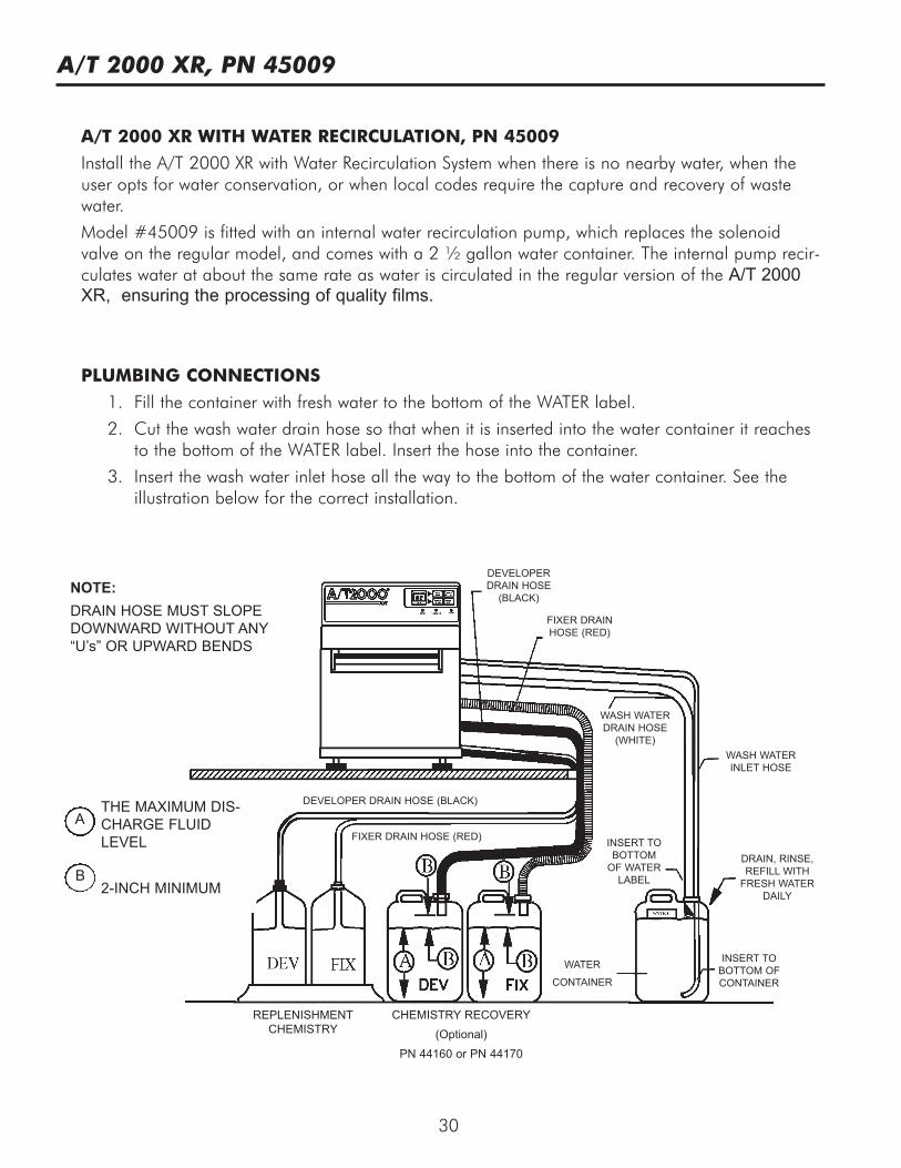
A/T 2000 XR WITH WATER RECIRCULATION, PN 45009
Install the A/T 2000 XR with Water Recirculation System when there is no nearby water, when theuser opts for water conservation, or when local codes require the capture and recovery of wastewater.
Model #45009 is fitted with an internal water recirculation pump, which replaces the solenoidvalve on the regular model, and comes with a 2 ½ gallon water container. The internal pump recir-culates water at about the same rate as water is circulated in the regular version of the A/T 2000XR, ensuring the processing of quality films.
PLUMBING CONNECTIONS
1. Fill the container with fresh water to the bottom of the WATER label.
2. Cut the wash water drain hose so that when it is inserted into the water container it reachesto the bottom of the WATER label. Insert the hose into the container.
3. Insert the wash water inlet hose all the way to the bottom of the water container. See theillustration below for the correct installation.
NOTE:DRAIN HOSE MUST SLOPEDOWNWARD WITHOUT ANY“U’s” OR UPWARD BENDS
REPLENISHMENTCHEMISTRY
CHEMISTRY RECOVERY(Optional)
PN 44160 or PN 44170
WATER
CONTAINER
INSERT TOBOTTOM OFCONTAINER
INSERT TOBOTTOMOF WATERLABEL
WASH WATERINLET HOSE
DRAIN, RINSE,REFILL WITHFRESH WATER
DAILY
WASH WATERDRAIN HOSE(WHITE)
FIXER DRAINHOSE (RED)
DEVELOPERDRAIN HOSE(BLACK)
FIXER DRAIN HOSE (RED)
DEVELOPER DRAIN HOSE (BLACK)THE MAXIMUM DIS-CHARGE FLUIDLEVEL
2-INCH MINIMUMB
A

31
A/T 2000 XR WITH WATER RECIRCULATION, PN 45009 (Continued)
OPERATION AND MAINTENANCE
Follow the same Daily Operation procedure detailed on pages 8 & 9 and the same Weekly,Monthly, and
Quarterly Maintenance procedures on pages.12-16. In addition change, the wash water daily.
Follow these steps:
AT THE END OF THE DAY:q Turn OFF the POWER switch.q Lift the processor cover and remove the wash tank drain tube. Completely drain the
Wash tank water into the water container. Reinstall the wash tank drain tube.q Remove the wash water inlet hose and the wash water drain hose from the water con-
tainer. Dispose of the used wash water in accordance with local codes and thoroughlyrinse the container with clean water.
q Fill with 2½ gallons of fresh water (to the bottom of the WATER label).q Insert the wash water inlet hose until it reaches the bottom of the container. Insert the
(white) wash water drain hose until it reaches the bottom of the WATER label. (The endof this drain hose must be above the water level in the bottle).
AT THE BEGINNING OF THE DAY:q Check that the wash water container is properly filled and connected.
A/T 2000 XR, PN 45009

For over 50 years, Air Techniques has been a leading innovator and manufacturer of dentalproducts. Our priority is ensuring complete satisfaction by manufacturing reliable products andproviding excellent customer and technical support. Whether the need is digital imaging, utilityroom equipment or merchandise, Air Techniques can provide the solution via our network ofauthorized professional dealers. Proudly designed, tested and manufactured in the U.S., ourproducts are helping dental professionals take their practices to the next level.
Air Techniques’ family of quality products for the dental professional include:
q Digital Imaging •Digital Radiography•Intraoral Camera•Caries Detection Aid•Intraoral X-ray•Film Processors
q Utility Room •Dry Vacuums•Wet Vacuums•Air Compressors•Amalgam Separator•Utility Accessories•Utility Packages
q Merchandise •Evacuation System Cleaner•Imaging Accessories•Chemistry•Processor Accessories
Corporate Headquarters1295 Walt Whitman Road | Melville, New York 11747- 3062 | Phone: 800-247-8324 | Fax: 888-247-8481
Western Facility291 Bonnie Lane, Suite 101 | Corona, CA 92880 - 2804 | Phone: 800-247-8324 | Fax: 951-898-7646
www.airtechniques.com
Scan QR Code for moreabout A/T 2000 XR.
© Air Techniques, Inc , P/N 45050 Rev. K January 2016