operator s manual - weingartz
TRANSCRIPT

P.O. BOX 361131 CLEVELAND, OHIO 44136-0019
Safe Operation Practices • Assembly & Set-Up • Controls & Operation • Service • Troubleshooting
WARNINGREAD AND FOLLOW ALL SAFETY RULES AND INSTRUCTIONS IN THIS MANUAL
BEFORE ATTEMPTING TO OPERATE THIS MACHINE. FAILURE TO COMPLY WITH THESE INSTRUCTIONS MAY RESULT IN PERSONAL INJURY.
OperatOr’s Manual
NOTE: This Operator’s Manual covers several models. Features may vary by model. Not all features in this manual are applicable to all models and the model depicted may differ from yours.
Form No. 769-14750A(October 13, 2020)
Lawn Edger — 520 Series, 550 Series
Safe Operation Practices ........................................ 2Assembly & Set-Up .................................................. 4Controls & Operation .............................................. 6Service ...................................................................... 8
Troubleshooting ...................................................... 9Español ........................................................................Replacement Parts ................................ supplementWarranty ................................................ supplement

Safe Operation Practices 1
2
Safe Handling Of Gasoline:To avoid personal injury or property damage use extreme care in handling gasoline. Gasoline is extremely flammable and the vapors are explosive. Serious personal injury can occur when gasoline is spilled on yourself or your clothes which can ignite. Wash your skin and change clothes immediately.
1. Use only an approved gasoline container.
2. Never fill containers inside a vehicle or on a truck or trailer bed with a plastic liner. Always place containers on the ground away from your vehicle before filling.
3. Remove gas-powered equipment from the truck or trailer and refuel it on the ground. If this is not possible, then refuel such equipment on a trailer with a portable container, rather than from a gasoline dispenser nozzle.
4. Keep the nozzle in contact with the rim of the fuel tank or container opening at all times until fueling is complete. Do not use a nozzle lock-open device.
5. Extinguish all cigarettes, cigars, pipes and other sources of ignition.
6. Never fuel machine indoors because flammable vapors will accumulate in the area.
7. Never remove gas cap or add fuel while engine is hot or running. Allow engine to cool at least two minutes before refueling.
8. Never over fill fuel tank. Fill tank to no more than 1/2” below bottom of filler neck to provide for fuel expansion.
9. Replace gasoline cap and tighten securely.
10. If gasoline is spilled, wipe it off the engine and equipment. Move machine to another area. Wait 5 minutes before starting engine.
11. Never store the machine or fuel container near an open flame, spark or pilot light as on a water heater, space heater, furnace, clothes dryer or other gas appliances.
12. To reduce fire hazard, keep lawn edger free of grass, leaves, or other debris build-up. Clean up oil or fuel spillage and remove any fuel soaked debris.
13. Allow a lawn edger to cool at least five (5) minutes before storing.
Operation1. Do not put hands or feet near rotating parts.
Contact with the rotating blade can amputate hands and feet.
Training1. Read this operator’s manual carefully in
its entirety before attempting to assemble this machine. Read, understand, and follow all instructions on the machine and in the manual(s) before operation. Keep this manual in a safe place for future and regular reference and for ordering replacement parts.
2. Be completely familiar with the controls and the proper use of this machine before operating it.
3. This machine is a precision piece of power equipment, not a plaything. Therefore, exercise extreme caution at all times. Your machine has been designed to perform one job: to edge lawn. Do not use it for any other purpose.
4. Never allow children under 14 years of age to operate this machine. Children 14 and over should read and understand the instructions and safe operation practices in this manual and on the machine and be trained and supervised by an adult.
5. Only responsible individuals who are familiar with these rules of safe operation should be allowed to use this machine.
6. To help avoid blade contact or a thrown object injury, stay in operator zone behind handles and keep children, bystanders, helpers and pets at least 75 feet from lawn edger while it is in operation. Stop machine if anyone enters area.
Preparation1. Thoroughly inspect the area where the
equipment is to be used. Remove all stones, sticks, wire, bones, toys and other foreign objects which could be tripped over or picked up and thrown by the blade. Thrown objects can cause serious personal injury.
2. Always wear safety glasses or safety goggles during operation and while performing an adjustment or repair to protect your eyes. Thrown objects which ricochet can cause serious injury to the eyes.
3. Wear sturdy, rough-soled work shoes and close-fitting slacks and shirts. Shirts and pants that cover the arms and legs and steel-toed shoes are recommended. Never operate this machine in bare feet, sandals, slippery or light weight (e.g. canvas) shoes.
4. Never attempt to make any adjustments while the engine is running, except where specifically recommended in the operator’s manual.
WARNING! This symbol points out important safety instructions which, if not followed, could endanger the personal safety and/or property of yourself and others. Read and follow all instructions in this manual before attempting to operate this machine. Failure to comply with these instructions may result in personal injury. When you see this symbol. HEED ITS WARNING!
CALIFORNIA PROPOSITION 65WARNING! Engine Exhaust, some of its constituents, and certain vehicle components contain or emit chemicals known to State of California to cause
cancer and birth defects or other reproductive harm.
DANGER! This machine was built to be operated according to the safe operation practices in this manual. As with any type of power equipment, carelessness or error on the part of the operator can result in serious injury. This machine is capable of amputating fingers, hands, toes and feet and throwing objects. Failure to observe the following safety instructions could result in serious injury or death.
2. The blade control handle is a safety device. Never bypass its operation. Doing so, makes the machine unsafe and may cause personal injury.
3. Never operate without blade guard, debris shield and blade control handle in place and working.
4. Never operate with damaged safety devices. Failure to do so, can result in personal injury.
5. Never run an engine indoors or in a poorly ventilated area. Engine exhaust contains carbon monoxide, an odorless and deadly gas.
6. Do not operate machine while under the influence of alcohol or drugs.
7. Muffler and engine become hot and can cause a burn. Do not touch.
8. Never operate this machine without good visibility or light. Always be sure of your footing and keep a firm hold on the handles. Walk, never run.
9. Do not operate this machine if it has been dropped or damaged. Return machine to your nearest authorized servicing dealer for examination and repair.
10. Do not operate this machine with a damaged or excessively worn cutting blade.
11. Never attempt to clear material from the blade guard while the engine is running. Shut the engine off, disconnect the spark plug wire and ground against the engine to prevent unintended starting.
12. Do not overload machine capacity by attempting to edge at too fast of a rate.
13. Stay alert for uneven sidewalks, terrain etc. Always push slowly over rough surfaces. Do not use this machine on gravel surfaces.
14. Do not operate machine in rain or wet soil conditions.
15. Always operate machine from behind the handles and position yourself where the direct line of sight to cutting blade is blocked by guards.
16. Always stop engine when edging or trimming is delayed or when transporting machine from one location to another.
17. Never leave a running machine unattended. Stop the engine, disconnect spark plug wire and ground against the engine to prevent unintended starting.
18. Only use parts and accessories made for this machine by the manufacturer. Failure to do so can result in personal injury.

3Section 1 — Safe operation practiceS
2. Before cleaning, repairing, or inspecting, make certain the blade and all moving parts have stopped. Disconnect the spark plug wire and ground against the engine to prevent unintended starting.
3. Check the blade and engine mounting bolts at frequent intervals for proper tightness. Also, visually inspect blade for damage (e.g., bent, cracked, worn) Replace blade with the original equipment manufacture’s (O.E.M.) blade only, listed in this manual. “Use of parts which do not meet the original equipment specifications may lead to improper performance and compromise safety!”
4. Lawn edger blades are sharp and can cut. Wrap the blade or wear gloves, and use extra caution when servicing them.
5. Keep all nuts, bolts, and screws tight to be sure the equipment is in safe working condition.
6. Never tamper with safety devices. Check their proper operation regularly.
7. After striking a foreign object, stop the engine, disconnect the spark plug wire and ground against the engine. Thoroughly inspect the lawn edger for any damage. Repair the damage before starting and operating the lawn edger.
8. Never attempt to make a wheel adjustment while the engine is running.
9. Many components on your new edger can wear with continued use. For safety protection, frequently check all edger components and replace immediately with original equipment manufacturer’s (O.E.M.) parts only, listed in this manual. “Use of parts which do not meet the original equipment specifications may lead to improper performance and compromise safety!”
10. Do not change the engine governor setting or overspeed the engine. The governor controls the maximum safe operating speed of the engine.
11. Maintain or replace safety and instruction labels, as necessary.
12. Observe proper disposal laws and regulations for used gas, oil, etc. Improper disposal of fluids and materials can harm the environment.
13. According to the Consumer Products Safety Commission (CPSC) and the U.S. Environmental Protection Agency (EPA), this product has an Average Useful Life of seven (7) years, or 70 hours of operation. At the end of the Average Useful Life have the machine inspected annually by an authorized service dealer to ensure that all mechanical and safety systems are working properly and not worn excessively. Failure to do so can result in accidents, injuries or death.
Spark ArrestorWARNING! This machine is equipped with an internal combustion engine and should not be used on or near any unimproved forest-covered, brushcovered or grass-covered land unless the engine’s exhaust system is equipped with a spark arrestor meeting applicable local or state laws (if any).
If a spark arrestor is used, it should be maintained in effective working order by the operator. In the State of California the above is required by law (Section 4442 of the California Public Resources Code). Other states may have similar laws. Federal laws apply on federal lands. A spark arrestor for the muffler is available through your nearest engine authorized service dealer or contact the service department, P.O. Box 361131 Cleveland, Ohio 44136-0019.
19. If situations occur which are not covered in this manual, use care and good judgment. Contact Customer Support for assistance or the name of your nearest service dealer.
ChildrenTragic accidents can occur if the operator is not alert to the presence of children. Children are often attracted to power equipment such as lawn edgers. They do not understand the dangers. Never assume that children will remain where you last saw them.
1. Keep children out of the edging area and under watchful care of a responsible adult other than the operator.
2. Be alert and turn lawn edger off if a child enters the area.
3. Before and while moving backwards, look behind and down for small children.
4. Use extreme care when approaching blind corners, doorways, shrubs, trees, or other objects that may obscure your vision of a child who may run into the lawn edger.
5. Keep children away from hot or running engines. They can suffer burns from a hot muffler.
6. Never allow children under 14 years of age to operate this machine. Children 14 and over should read and understand the instructions and safe operation practices in this manual and on the machine and be trained and supervised by an adult.
Maintenance and Storage 1. Never run an engine indoors or in a poorly
ventilated area. Engine exhaust contains carbon monoxide, an odorless and deadly gas.
Safety SymbolsThis page depicts and describes safety symbols that may appear on this product. Read, understand, and follow all instructions on the machine before attempting to assemble and operate.
Symbol Description
READ THE OPERATOR’S MANUAL(S) Read, understand, and follow all instructions in the manual(s) before attempting to assemble and operate.
WARNING— ROTATING BLADES Keep hands and feet away from rotating blade.
BYSTANDERS Keep bystanders, pets, and children at least 75 feet from the machine while it is in operation. Stop machine if anyone enters the area.
WARNING— HOT SURFACES Do not touch muffler or adjacent areas.
EYE PROTECTION Always wear safety glasses or safety goggles when operating this machine.
WARNING! Your Responsibility—Restrict the use of this power machine to persons who read, understand and follow the warnings and instructions in this manual and on the machine.
SAVE THESE INSTRUCTIONS!

Assembly & Set-Up 2
4
NOTE: This machine is shipped WITHOUT GASOLINE or OIL. After setting up the edger, service the engine with gasoline and oil as instructed in the Engine Operator’s Manual.
NOTE: Reference to right or left hand side of the edger is observed from the operating position.
AssemblyHandleRemove and discard any packaging cardboard that may be present between the upper handle and the lower handle.
1. Pivot the upper handle upward until it snaps into place. See 1 in Figure 2-1.
1
2
Figure 2-1
2. Tighten the star knobs (a), which are located on both the left and right sides of the handle. See 2 in Figure 2-1.
Control Cable Z-FittingUnwrap the control cable from the engine and route it under the lower handle.
1. Hook the Z end of the brake cable into the control from the outside to inside. See Figure 2-2.
Z-Fitting
Blade Control
Upper Handle
Figure 2-2
Securing Control CableWARNING: The cable must be routed properly to avoid contact with all sharp edges and hot surfaces. Such contacts damage the cable and render the controls inoperative.
1. Press the stud found inside the snap fitting into the hole found on the left side of the upper handle, as shown in Figure 2-3.
Upper Handle
1
2
Stud
Snap Snap FittingFitting
Figure 2-32. Push the snap fitting down on the handle to
secure it into place.
• Edger (1) • Wing Knob and Rope Guide (1) • Trenching Blade Kit † (1)
• Edger Operator’s Manual (1) • Engine Operator’s Manual (1) • Fast Start Guide † (1)
• Registration Card (1) • Parts/Warranty Supplement Sheet (1) • Oil (1)
† If Equipped
Contents of Carton
Thank you for purchasing this product. It was carefully engineered to provide excellent performance when properly operated and maintained.
Please read this entire manual prior to operating the equipment. It instructs you how to safely and easily set up, operate and maintain your machine. Please be sure that you, and any other persons who will operate the machine, carefully follow the recommended safety practices at all times. Failure to do so could result in personal injury or property damage.
All information in this manual is relative to the most recent product information available at the time of printing. Review this manual frequently to familiarize yourself with the machine, its features and operation. Please be aware that this Operator’s Manual may cover a range of product specifications for various models. Characteristics and features discussed and/or illustrated in this manual may not be applicable to all models. We reserve the right to change product specifications, designs and equipment without notice and without incurring obligation.
If applicable, the power testing information used to establish the power rating of the engine equipped on this machine can be found at www.opei.org or the engine manufacturer’s web site.
If you have any problems or questions concerning the machine, phone an authorized service dealer or contact us directly. Customer Support telephone numbers, website address and mailing address can be found on this page. We want to ensure your complete satisfaction at all times.
Throughout this manual, all references to right and left side of the machine are observed from the operating position.
The engine manufacturer is responsible for all engine-related issues with regards to performance, power-rating, specifications, warranty and service. Please refer to the engine manufacturer’s Owner’s/Operator’s Manual, packed separately with your machine, for more information.
Thank You

5Section 2 — ASSembly & Set-Up
Securing Blade Depth Control CableUnwrap the blade depth control cable from around the rear axle and route it up through the slot on the frame and up the right side of the handle.
1. Pull the depth control lever out of the first position of the depth control bracket.
2. Push lever all the way forward.
3. Release lever into last position of bracket.
4. Hook the Z end of the depth control cable into the hole on the depth control lever as shown in Figure 2-4.
1
2
3
4
Figure 2-4
Starter RopeLocate the rope guide and wing knob found in the manual bag. Using the wing knob (a), secure but do not tighten the rope guide to the right side of the upper handle.
1. Stand behind the edger and hold the blade control against the upper handle. See Figure 2-5.
1
2
3
4
(a)
Figure 2-52. Gently pull the starter rope out of the engine.
WARNING! The edger blade WILL rotate when the starter rope is pulled.
NOTE: The starter rope will not pull out of the engine unless the blade control (refer to Figure 2-5) is depressed against the upper handle.
3. Slip the starter rope through the top of the rope guide.
4. Tighten the wing knob (a) which secures the rope guide to the upper handle.
AdjustmentsBevel Adjustment (IF EQUIPPED)The angle of the edger blade can be adjusted by placing the bevel adjustment in one of three positions for edging. See Figure 2-6.
Figure 2-6
Controls & Operation 3
6
Blade Control
Blade Depth Control Lever
Recoil Starter
Bevel Adjustment Lever
Blade Control
Blade Depth Control Lever
Recoil Starter
Curb Height Adjustment Lever
550520
Primer
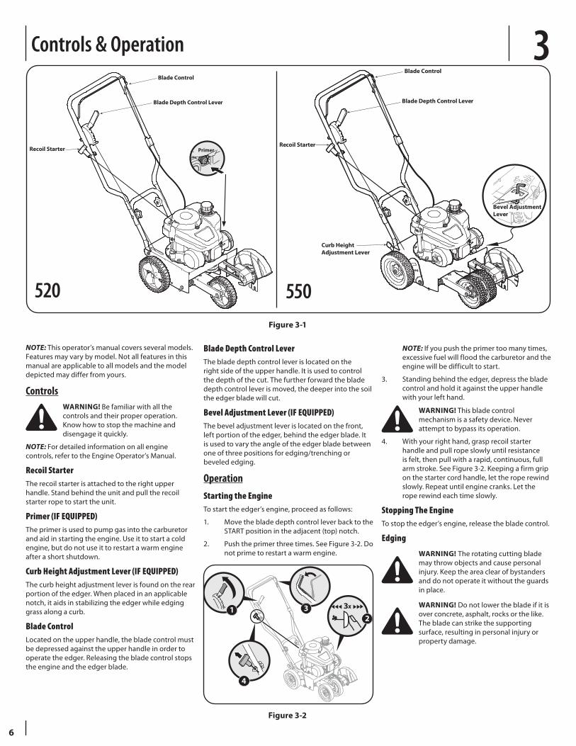
Figure 3-1
NOTE: This operator’s manual covers several models. Features may vary by model. Not all features in this manual are applicable to all models and the model depicted may differ from yours.
ControlsWARNING! Be familiar with all the controls and their proper operation. Know how to stop the machine and disengage it quickly.
NOTE: For detailed information on all engine controls, refer to the Engine Operator’s Manual.
Recoil StarterThe recoil starter is attached to the right upper handle. Stand behind the unit and pull the recoil starter rope to start the unit.
Primer (IF EQUIPPED)The primer is used to pump gas into the carburetor and aid in starting the engine. Use it to start a cold engine, but do not use it to restart a warm engine after a short shutdown.
Curb Height Adjustment Lever (IF EQUIPPED)The curb height adjustment lever is found on the rear portion of the edger. When placed in an applicable notch, it aids in stabilizing the edger while edging grass along a curb.
Blade ControlLocated on the upper handle, the blade control must be depressed against the upper handle in order to operate the edger. Releasing the blade control stops the engine and the edger blade.
Blade Depth Control LeverThe blade depth control lever is located on the right side of the upper handle. It is used to control the depth of the cut. The further forward the blade depth control lever is moved, the deeper into the soil the edger blade will cut.
Bevel Adjustment Lever (IF EQUIPPED)The bevel adjustment lever is located on the front, left portion of the edger, behind the edger blade. It is used to vary the angle of the edger blade between one of three positions for edging/trenching or beveled edging.
OperationStarting the EngineTo start the edger’s engine, proceed as follows:
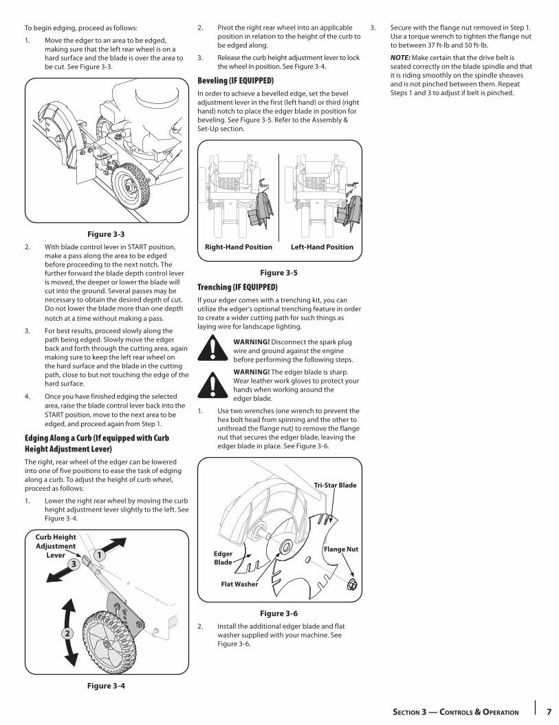
1. Move the blade depth control lever back to the START position in the adjacent (top) notch.
2. Push the primer three times. See Figure 3-2. Do not prime to restart a warm engine.
3
4
21
Figure 3-2
NOTE: If you push the primer too many times, excessive fuel will flood the carburetor and the engine will be difficult to start.
3. Standing behind the edger, depress the blade control and hold it against the upper handle with your left hand.
WARNING! This blade control mechanism is a safety device. Never attempt to bypass its operation.
4. With your right hand, grasp recoil starter handle and pull rope slowly until resistance is felt, then pull with a rapid, continuous, full arm stroke. See Figure 3-2. Keeping a firm grip on the starter cord handle, let the rope rewind slowly. Repeat until engine cranks. Let the rope rewind each time slowly.
Stopping The EngineTo stop the edger’s engine, release the blade control.
Edging
WARNING! The rotating cutting blade may throw objects and cause personal injury. Keep the area clear of bystanders and do not operate it without the guards in place.
WARNING! Do not lower the blade if it is over concrete, asphalt, rocks or the like. The blade can strike the supporting surface, resulting in personal injury or property damage.
7Section 3 — controlS & operation
To begin edging, proceed as follows:
1. Move the edger to an area to be edged, making sure that the left rear wheel is on a hard surface and the blade is over the area to be cut. See Figure 3-3.
Figure 3-32. With blade control lever in START position,
make a pass along the area to be edged before proceeding to the next notch. The further forward the blade depth control lever is moved, the deeper or lower the blade will cut into the ground. Several passes may be necessary to obtain the desired depth of cut. Do not lower the blade more than one depth notch at a time without making a pass.
3. For best results, proceed slowly along the path being edged. Slowly move the edger back and forth through the cutting area, again making sure to keep the left rear wheel on the hard surface and the blade in the cutting path, close to but not touching the edge of the hard surface.
4. Once you have finished edging the selected area, raise the blade control lever back into the START position, move to the next area to be edged, and proceed again from Step 1.
Edging Along a Curb (If equipped with Curb Height Adjustment Lever)The right, rear wheel of the edger can be lowered into one of five positions to ease the task of edging along a curb. To adjust the height of curb wheel, proceed as follows:
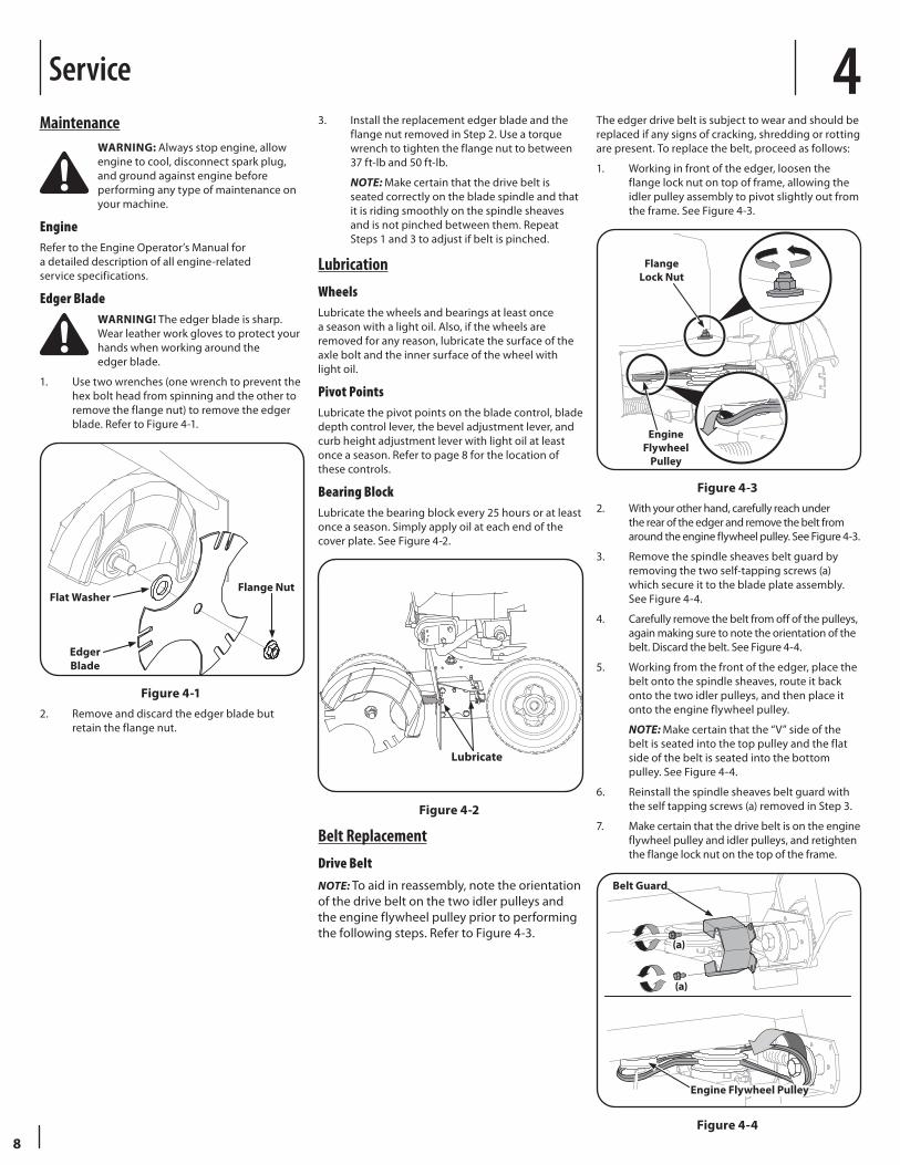
1. Lower the right rear wheel by moving the curb height adjustment lever slightly to the left. See Figure 3-4.
3
2
1
Curb HeightAdjustment
Lever
Figure 3-4
2. Pivot the right rear wheel into an applicable position in relation to the height of the curb to be edged along.
3. Release the curb height adjustment lever to lock the wheel in position. See Figure 3-4.
Beveling (IF EQUIPPED)In order to achieve a bevelled edge, set the bevel adjustment lever in the first (left hand) or third (right hand) notch to place the edger blade in position for beveling. See Figure 3-5. Refer to the Assembly & Set-Up section.
Right-Hand Position Left-Hand Position
Figure 3-5
Trenching (IF EQUIPPED)If your edger comes with a trenching kit, you can utilize the edger’s optional trenching feature in order to create a wider cutting path for such things as laying wire for landscape lighting.
WARNING! Disconnect the spark plug wire and ground against the engine before performing the following steps.
WARNING! The edger blade is sharp. Wear leather work gloves to protect your hands when working around the edger blade.
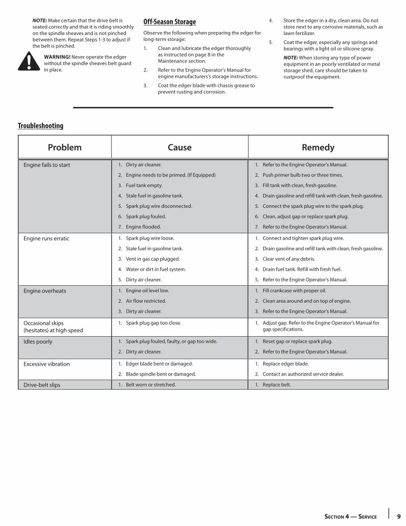
1. Use two wrenches (one wrench to prevent the hex bolt head from spinning and the other to unthread the flange nut) to remove the flange nut that secures the edger blade, leaving the edger blade in place. See Figure 3-6.
Flange Nut
Flat Washer
Edger Blade
Tri-Star Blade
Figure 3-62. Install the additional edger blade and flat
washer supplied with your machine. See Figure 3-6.
3. Secure with the flange nut removed in Step 1. Use a torque wrench to tighten the flange nut to between 37 ft-lb and 50 ft-lb.
NOTE: Make certain that the drive belt is seated correctly on the blade spindle and that it is riding smoothly on the spindle sheaves and is not pinched between them. Repeat Steps 1 and 3 to adjust if belt is pinched.
Service 4
8
MaintenanceWARNING: Always stop engine, allow engine to cool, disconnect spark plug, and ground against engine before performing any type of maintenance on your machine.
EngineRefer to the Engine Operator’s Manual for a detailed description of all engine-related service specifications.
Edger BladeWARNING! The edger blade is sharp. Wear leather work gloves to protect your hands when working around the edger blade.
1. Use two wrenches (one wrench to prevent the hex bolt head from spinning and the other to remove the flange nut) to remove the edger blade. Refer to Figure 4-1.
Flange Nut
Edger Blade
Flat Washer
Figure 4-12. Remove and discard the edger blade but
retain the flange nut.
3. Install the replacement edger blade and the flange nut removed in Step 2. Use a torque wrench to tighten the flange nut to between 37 ft-lb and 50 ft-lb.
NOTE: Make certain that the drive belt is seated correctly on the blade spindle and that it is riding smoothly on the spindle sheaves and is not pinched between them. Repeat Steps 1 and 3 to adjust if belt is pinched.
LubricationWheelsLubricate the wheels and bearings at least once a season with a light oil. Also, if the wheels are removed for any reason, lubricate the surface of the axle bolt and the inner surface of the wheel with light oil.
Pivot PointsLubricate the pivot points on the blade control, blade depth control lever, the bevel adjustment lever, and curb height adjustment lever with light oil at least once a season. Refer to page 8 for the location of these controls.
Bearing BlockLubricate the bearing block every 25 hours or at least once a season. Simply apply oil at each end of the cover plate. See Figure 4-2.
Lubricate
Figure 4-2
Belt ReplacementDrive Belt
NOTE: To aid in reassembly, note the orientation of the drive belt on the two idler pulleys and the engine flywheel pulley prior to performing the following steps. Refer to Figure 4-3.
The edger drive belt is subject to wear and should be replaced if any signs of cracking, shredding or rotting are present. To replace the belt, proceed as follows:
1. Working in front of the edger, loosen the flange lock nut on top of frame, allowing the idler pulley assembly to pivot slightly out from the frame. See Figure 4-3.
FlangeLock Nut
EngineFlywheel
Pulley
Figure 4-32. With your other hand, carefully reach under
the rear of the edger and remove the belt from around the engine flywheel pulley. See Figure 4-3.
3. Remove the spindle sheaves belt guard by removing the two self-tapping screws (a) which secure it to the blade plate assembly. See Figure 4-4.
4. Carefully remove the belt from off of the pulleys, again making sure to note the orientation of the belt. Discard the belt. See Figure 4-4.
5. Working from the front of the edger, place the belt onto the spindle sheaves, route it back onto the two idler pulleys, and then place it onto the engine flywheel pulley.
NOTE: Make certain that the “V” side of the belt is seated into the top pulley and the flat side of the belt is seated into the bottom pulley. See Figure 4-4.
6. Reinstall the spindle sheaves belt guard with the self tapping screws (a) removed in Step 3.
7. Make certain that the drive belt is on the engine flywheel pulley and idler pulleys, and retighten the flange lock nut on the top of the frame.
Engine Flywheel Pulley
Belt Guard
(a)
(a)
(a)
(a)
Figure 4-4
9Section 4 — Service
NOTE: Make certain that the drive belt is seated correctly and that it is riding smoothly on the spindle sheaves and is not pinched between them. Repeat Steps 1-3 to adjust if the belt is pinched.
WARNING! Never operate the edger without the spindle sheaves belt guard in place.
Off-Season StorageObserve the following when preparing the edger for long-term storage:
1. Clean and lubricate the edger thoroughly as instructed on page 8 in the Maintenance section.
2. Refer to the Engine Operator’s Manual for engine manufacturers’s storage instructions.
3. Coat the edger blade with chassis grease to prevent rusting and corrosion.
Problem Cause Remedy
Engine fails to start 1. Dirty air cleaner.
2. Engine needs to be primed. (If Equipped)
3. Fuel tank empty.
4. Stale fuel in gasoline tank.
5. Spark plug wire disconnected.
6. Spark plug fouled.
7. Engine flooded.
1. Refer to the Engine Operator’s Manual.
2. Push primer bulb two or three times.
3. Fill tank with clean, fresh gasoline.
4. Drain gasoline and refill tank with clean, fresh gasoline.
5. Connect the spark plug wire to the spark plug.
6. Clean, adjust gap or replace spark plug.
7. Refer to the Engine Operator’s Manual.
Engine runs erratic 1. Spark plug wire loose.
2. Stale fuel in gasoline tank.
3. Vent in gas cap plugged.
4. Water or dirt in fuel system.
5. Dirty air cleaner.
1. Connect and tighten spark plug wire.
2. Drain gasoline and refill tank with clean, fresh gasoline.
3. Clear vent of any debris.
4. Drain fuel tank. Refill with fresh fuel.
5. Refer to the Engine Operator’s Manual.
Engine overheats 1. Engine oil level low.
2. Air flow restricted.
3. Dirty air cleaner.
1. Fill crankcase with proper oil.
2. Clean area around and on top of engine.
3. Refer to the Engine Operator’s Manual.
Occasional skips(hesitates) at high speed
1. Spark plug gap too close. 1. Adjust gap. Refer to the Engine Operator’s Manual for gap specifications.
Idles poorly 1. Spark plug fouled, faulty, or gap too wide.
2. Dirty air cleaner.
1. Reset gap or replace spark plug.
2. Refer to the Engine Operator’s Manual.
Excessive vibration 1. Edger blade bent or damaged.
2. Blade spindle bent or damaged.
1. Replace edger blade.
2. Contact an authorized service dealer.
Drive-belt slips 1. Belt worn or stretched. 1. Replace belt.
Troubleshooting
4. Store the edger in a dry, clean area. Do not store next to any corrosive materials, such as lawn fertilizer.
5. Coat the edger, especially any springs and bearings with a light oil or silicone spray.
NOTE: When storing any type of power equipment in an poorly ventilated or metal storage shed, care should be taken to rustproof the equipment.

Notes
10
P.O. BOX 361131 CLEVELAND, OHIO 44136-0019
Bordeadora de césped — Modelo serie 520, 550
Manual del operador
Medidas de seguridad • Montaje y Configuración • Controles y Funcionamiento • Servicio • Solución de problemas
ADVERTENCIALEA Y SIGA TODAS LAS INSTRUCCIONES DE ESTE MANUAL ANTES DE PONER EN
FUNCIONAMIENTO ESTA MÁQUINA. SI NO RESPETA ESTAS INSTRUCCIONES PUEDE PROVOCAR LESIONES PERSONALES.
NOTA: Este manual del operador cubre varios modelos. Las características técnicas pueden variar de acuerda al modelo. No todas las características incluidas en este manual se aplican a todos los modelos y el modelo ilustrado puede ser diferente al suyo.
Formulario No. 769-14750A(13 de octubre de 2020)
ÍndiceMedidas de seguridad ............................................ 2Montaje y Configuración ........................................ 4Controles y Funcionamiento .................................. 6
Servicio ..................................................................... 8Solución de Problemas ........................................... 9Garantía ................................................. suplemento

Medidas de seguridad 1
2
Manejo seguro de la gasolina:1. Para evitar lesiones personales o daños
materiales sea sumamente cuidadoso al manipular la gasolina. La gasolina es sumamente inflamable y sus vapores pueden causar explosiones. Si se derrama gasolina encima o sobre la ropa se puede lesionar gravemente ya que se puede incendiar. Lávese la piel y cámbiese de ropa de inmediato.
a. Utilice sólo recipientes para gasolina autorizados.
b. Nunca llene los recipientes en el interior de un vehículo o camión o caja de remolque con recubrimiento plástico. Coloque siempre los recipientes en el piso y lejos del vehículo antes de realizar la carga.
c. Retire el equipo a gasolina del camión o remolque y llénelo en el piso. Si esto no es posible, llene el equipo en un remolque con un contenedor portátil, en vez de hacerlo con una boquilla dispensadora de gasolina.
d. Mantenga la boquilla de llenado en contacto con el borde del depósito de combustible o con la abertura del recipiente en todo momento, hasta terminar la carga. No utilice un dispositivo de boquilla de apertura/cierre.
e. Apague todos los cigarrillos, cigarros, pipas y otras fuentes de combustión.
f. Nunca cargue combustible en la máquina en interiores porque los vapores inflamables podrían acumularse en el área.
g. Nunca saque la tapa de la gasolina ni agregue combustible mientras el motor está caliente o en marcha. Deje que el motor se enfríe por lo menos dos minutos antes de volver a cargar combustible.
h. Nunca llene en exceso el depósito de combustible. Llene el tanque a no más de 1/2 pulgada por debajo de la base del cuello del tapón de carga, para permitir la expansión del combustible.
i. Vuelva a colocar la tapa de la gasolina y ajústela bien.
j. Limpie el combustible que se haya derramado sobre el motor y el equipo. Traslade la máquina a otra zona. Espere 5 minutos antes de encender el motor.
k. Nunca almacene la máquina o el recipiente de combustible cerca de llama expuesta, chispas o aparatos con piloto como por ejemplo, calentadores de agua, calefactores, hornos, secadores de ropa u otros aparatos a gas.
l. Para reducir el riesgo de incendio mantenga la bordeadora de césped limpia de pasto, hojas y de la acumulación de otros desechos. Limpie los derrames de aceite o combustible y saque todos los residuos embebidos de combustible.
Capacitación1. Lea con atención todas las instrucciones
contenidas en este manual antes de intentar ensamblar esta máquina. Lea, comprenda y respete todas las instrucciones que figuran en la máquina y en el o los manuales antes de hacerla funcionar. Guarde este manual en un lugar seguro para consultas futuras y periódicas, así como para solicitar repuestos.
2. Antes de operar este equipo, familiarícese totalmente con los controles y el uso correcto del mismo.
3. Esta máquina es una unidad de equipo motorizado de precisión, no un juguete. Por lo tanto, tenga mucho cuidado en todo momento. Esta máquina fue diseñada para realizar una tarea: bordear el césped. No la utilice para ningún otro fin.
4. No permita nunca que los niños menores de 14 años utilicen esta máquina. Los niños de 14 años en adelante deben leer y entender las instrucciones de operación y normas de seguridad contenidas en este manual, y en la máquina y deben ser entrenados y supervisados por un adulto.
5. Sólo se debe permitir usar esta máquina a individuos responsables y familiarizados con sus reglas de seguridad.
6. Para ayudar a evitar el contacto con la cuchilla o una lesión por un objeto arrojado, manténgase en la zona del operador detrás de las manijas y mantenga a los niños, observadores, ayudantes y mascotas apartados al menos 25 metros de la bordeadora de césped mientras está en operación. Detenga la máquina si alguien entra en la zona.
Preparativos1. Inspeccione minuciosamente el área donde
utilizará el equipo. Retire todas las piedras, palos, llantas, huesos, juguetes y otros objetos extraños que podrían hacer tropezar y caer o ser recogidos y arrojados por la acción de las cuchillas. Los objetos arrojados por la máquina pueden producir lesiones graves.
2. Para protegerse los ojos utilice siempre anteojos o antiparras de seguridad mientras opera la máquina o mientras la ajusta o repara. Los objetos arrojados que rebotan pueden producir lesiones oculares graves.
3. Utilice zapatos de trabajo resistentes, de suela fuerte, así como pantalones y camisas ajustados. Se recomienda vestir camisa y pantalón para cubrir brazos y piernas y usar zapatos con puntera de acero. Nunca opere esta máquina descalzo, con sandalias, zapatos resbalosos o livianos (por ej. de lona).
4. Nunca intente realizar ajustes mientras el motor está en marcha excepto en los casos específicamente recomendados en el manual del operador.
PROPOSICIÓN 65 DE CALIFORNIA¡ADVERTENCIA! El escape del motor de este producto, algunos de sus componentes y algunos componentes del vehículo contienen o liberan sustancias químicas que el estado de California considera que pueden producir cáncer, defectos de nacimiento u otros problemas reproductivos.
¡PELIGRO! Esta máquina está diseñada para ser utilizada respetando las normas de seguridad contenidas en este manual. Al igual que con cualquier tipo de equipo motorizado, un descuido o error por parte del operador puede producir lesiones graves. Esta máquina es capaz de amputar dedos, manos y pies y de arrojar objetos. De no respetar las instrucciones de seguridad siguientes se pueden producir lesiones graves o la muerte.
m. Deje que la bordeadora de césped se enfríe cinco (5) minutos por lo menos antes de almacenarla.
Funcionamiento1. No coloque las manos ni los pies cerca de las
piezas giratorias. El contacto con la cuchilla giratoria puede producir la amputación de manos y pies.
2. El mecanismo de control de la cuchilla es un dispositivo de seguridad. Nunca evite su funcionamiento. Si lo hace, la máquina se torna peligrosa y puede causar lesiones personales.
3. Nunca haga funcionar la bordeadora sin usar el protector de la cuchilla, el escudo contra escombros y la manija de control de la cuchilla en el lugar correspondiente y en funcionamiento.
4. Nunca opere la bordeadora si los dispositivos de seguridad están dañados. Si no lo hace, pueden producirse lesiones personales.
5. Nunca encienda el motor en espacios cerrados o en una zona con poca ventilación. El escape del motor contiene monóxido de carbono, un gas inodoro y letal.
6. No utilice la máquina bajo la influencia del alcohol o las drogas.
7. El silenciador y el motor se calientan y pueden causar quemaduras. No los toque.
8. Nunca opere esta máquina sin buena visibilidad o iluminación. Siempre debe estar seguro de que está bien afirmado y sujetando firmemente las manijas. Camine, nunca corra.
9. No opere esta máquina si se ha caído o está dañada. Regrese la máquina al servicio técnico de su distribuidor autorizado más cercano para que la examine y la repare.
10. No haga funcionar la máquina si la cuchilla de corte está dañada o excesivamente desgastada.
11. Nunca intente sacar material del protector de la cuchilla si el motor está en funcionamiento. Apague el motor, desconecte el cable de la bujía y póngalo de manera que haga masa contra el motor para evitar que se encienda accidentalmente.
12. No sobrecargue la capacidad de la máquina tratando de bordear a una velocidad demasiado rápida.
13. Manténgase alerta para advertir la existencia de aceras o terreno desparejos, etc. Siempre empuje lentamente sobre las superficies ásperas. No utilice esta máquina sobre pedregullo.
14. No opere la máquina bajo la lluvia o en condiciones de suelo húmedo.
15. Siempre haga funcionar la máquina desde detrás de las manijas y colóquese de modo que la línea de vista directa hacia la cuchilla de corte quede bloqueada por los protectores.
16. Siempre detenga el motor cuando el bordeado o recorte se vean demorados o cuando esté trasladando la máquina de un lugar a otro.
17. Nunca deje la máquina en funcionamiento sin vigilancia. Detenga el motor, desconecte el cable de la bujía y póngalo de manera que haga masa contra el motor para evitar que se encienda accidentalmente.
¡ADVERTENCIA! La presencia de este símbolo indica que se trata de instrucciones importantes de seguridad que se deben respetar para evitar poner en peligro su seguridad personal y/o material y la de otras personas. Lea y siga todas las instrucciones de este manual antes de poner en funcionamiento esta máquina. Si no respeta estas instrucciones puede provocar lesiones personales. Cuando vea este símbolo. ¡TENGA EN CUENTAS LAS ADVERTENCIAS!
3Sección 1 — MedidaS de Seguridad
2. Antes de limpiar, reparar o inspeccionar la máquina, compruebe que la cuchilla y todas las partes móviles se hayan detenido. Desconecte el cable de la bujía y póngalo haciendo masa contra el motor para evitar que se encienda accidentalmente.
3. Revise los pernos de montaje de la cuchilla y del motor a intervalos frecuentes para verificar que estén bien apretados. Inspeccione además visualmente la cuchilla en busca de daños (abolladuras, desgaste, roturas, etc). Reemplace la cuchilla únicamente con equipo original del fabricante (OEM) listado en este manual. “El uso de piezas que no cumplen con las especificaciones del equipo original podría tener como resultado un rendimiento incorrecto y además poner en riesgo la seguridad”.
4. Las cuchillas de las bordeadoras de césped son muy afiladas y pueden producir cortaduras. Envuelva la cuchilla o utilice guantes y extreme las precauciones cuando efectúe mantenimiento.
5. Mantenga todos los pernos, tuercas y tornillos bien ajustados para asegurarse de que la máquina se encuentra en condiciones seguras de operación.
6. Nunca altere los dispositivos de seguridad. Controle periódicamente que funcionen correctamente.
7. Después de golpear con algún objeto extraño, detenga el motor, desconecte el cable de la bujía y conecte el motor a masa. Inspeccione minuciosamente la bordeadora de césped para ver si está dañada. Repare el daño antes de arrancar y operar la bordeadora.
8. Nunca intente ajustar una rueda mientras el motor está en marcha.
9. Muchos componentes de la nueva bordeadora se desgastan en razón del uso continuo. Para proteger su seguridad, verifique frecuentemente todos los componentes de la bordeadora y reemplácelos inmediatamente sólo con piezas de los fabricantes de equipos originales (O.E.M.) listadas en este manual. “El uso de piezas que no cumplen con las especificaciones del equipo original podría tener como resultado un rendimiento incorrecto y además poner en riesgo la seguridad”.
10. No cambie la configuración del regulador del motor ni acelere demasiado el mismo. El regulador del motor controla la velocidad máxima segura de funcionamiento del motor.
11. Mantenga o reemplace las etiquetas de seguridad e instrucciones según sea necesario.
12. Respete las leyes y regulaciones de eliminación correspondientes para desechar la gasolina, el aceite, etc., usados. La eliminación inapropiada de líquidos o materiales puede dañar el medio ambiente.
Amortiguador de chispas¡ADVERTENCIA! Esta máquina está equipada con un motor de combustión interna y no debe ser utilizada en un terreno agreste cubierto por bosque, malezas o hierba ni cerca del mismo excepto que el sistema de escape del motor esté equipado con un amortiguador de chispas que cumpla con las leyes locales o estatales correspondientes (en caso de haber).Si se utiliza un amortiguador de chispas el operador lo debe mantener en condiciones
de uso adecuadas. En el Estado de California las medidas anteriormente mencionadas son exigidas por ley (Artículo 4442 del Código de Recursos Públicos de California). Es posible que existan leyes similares en otros estados. Las leyes federales se aplican en territorios federales. Puede conseguir el amortiguador de chispas para el silenciador a través de su distribuidor de mantenimiento de motores autorizado más cercano o poniéndose en contacto con el departamento de servicios, Apartado Postal 361131 Cleveland, Ohio 44136-0019.Vida útil mediaSegún la Comisión de Seguridad de Productos para el Consumidor de los Estados Unidos (CPSC) y la Agencia de Protección Ambiental de los Estados Unidos (EPA), este producto tiene una vida útil media de siete (7) años ó 70 horas de funcionamiento. Al finalizar la vida útil media, adquiera una máquina nueva o haga inspeccionar anualmente ésta por un distribuidor de servicio autorizado para cerciorarse de que todos los sistemas mecánicos y de seguridad funcionan correctamente y no tienen excesivo desgaste. Si no lo hace, pueden producirse accidentes, lesiones o muerte.
18. Utilice solamente piezas y accesorios manufacturados para esta máquina por el fabricante. Si no lo hace, pueden producirse lesiones personales.
19. Si se presentan situaciones que no están previstas en este manual, sea cuidadoso y use el sentido común. Póngase en contacto con Asistencia al Cliente para solicitar ayuda o el nombre del distribuidor de servicio más cercano a su domicilio.
NiñosPueden ocurrir accidentes trágicos si el operador no está atento a la presencia de niños. Por lo general, los niños se sienten atraídos por equipos motorizados tales como las bordeadoras de césped. No entienden los riesgos ni los peligros. Nunca asuma que los niños permanecerán en el mismo lugar donde los vio por última vez.1. Mantenga a los niños fuera del área de
bordeado y bajo estricta vigilancia de un adulto responsable además del operador.
2. Esté alerta y apague la bordeadora de césped si un niño ingresa al área.
3. Antes de moverse hacia atrás y mientras lo esté haciendo, mire hacia atrás y cuide que no haya niños.
4. Tenga extrema precaución cuando se aproxime a esquinas ciegas, entradas de puertas, arbustos, árboles u otros objetos que puedan obstaculizarle la vista de un niño que pudiese toparse con la bordeadora de césped.
5. Mantenga a los niños alejados de los motores en marcha o calientes. Pueden sufrir quemaduras con un silenciador caliente.
6. No permita nunca que los niños menores de 14 años utilicen esta máquina. Los niños de 14 años en adelante deben leer y entender las instrucciones de operación y normas de seguridad contenidas en este manual y en la máquina y deben ser entrenados y supervisados por un adulto.
Mantenimiento y almacenamiento 1. Nunca encienda el motor en espacios cerrados
o en una zona con poca ventilación. El escape del motor contiene monóxido de carbono, un gas inodoro y letal.
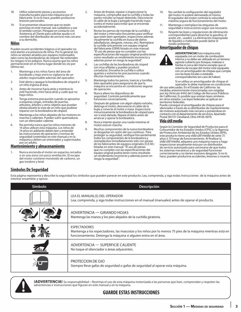
Símbolos De SeguridadEsta página representa y describe la seguridad los símbolos que pueden parecer en este producto. Lea, comprenda, y siga todas instrucciones de la máquina antes de intentar ensamblar y operar.
Símbolo Descripción
LEA EL MANUAL(S) DEL OPERADORLea, comprenda, y siga todas instrucciones en el manual (manuales) antes de operar el producto.
ADVERTENCIA — GIRANDO HOJASMantenga las manos y los pies alejados de la cuchilla giratoria.
ESPECTADORES Mantenga a los espectadores, las mascotas y los niños por lo menos 75 pies de la máquina mientras está en funcionamiento. Detenga la máquina si alguien entra en el área.
ADVERTENCIA — SUPERFICIE CALIENTENo toque el silenciador o áreas adyacentes.
PROTECCION DE OJO Siempre lleve gafas de seguridad o gafas de seguridad al operar esta máquina.
¡ADVERTENCIA! Su responsabilidad—Restrinja el uso de esta máquina motorizada a las personas que lean, comprendan y respeten las advertencias e instrucciones que figuran en este manual y en la máquina.
GUARDE ESTAS INSTRUCCIONES
Montaje y Configuración 2
4
• Bordeadora de césped (1) • Guía de la cuerda y perilla de aletas (1) • Kit de hacer trincheras† (1)
• Manual de Operador (1) • Manual de Operador de Motor (1) • Guía de inicio † (1)
• tarjeta de registro (1) • Oja de suplemento para la garantía (1) • Botella de aceite (1)
NOTA: Esta unidad se entrega SIN GASOLINA ni ACEITE. Después de armar la unidad, realice la carga de gasolina del motor según las instrucciones del manual del motor que se entrega con la unidad.
NOTA: En este manual, las referencias al lado derecho o izquierdo de la máquina se observan desde la posición del operador.
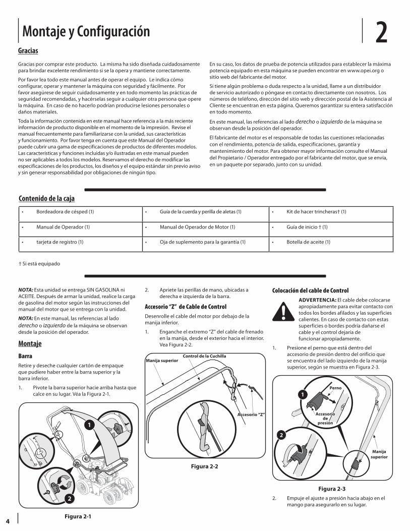
MontajeBarraRetire y deseche cualquier cartón de empaque que pudiere haber entre la barra superior y la barra inferior.
1. Pivote la barra superior hacie arriba hasta que calce en su lugar. Véa la Figura 2-1.
1
2
Figura 2-1
2. Apriete las perillas de mano, ubicadas a derecha e izquierda de la barra.
Accesorio “Z” de Cable de ControlDesenrolle el cable del motor por debajo de la manija inferior.
1. Enganche el extremo “Z” del cable de frenado en la manija, desde el exterior hacia el interior. Vea Figura 2-2.
Control de la CuchillaManija superior
Accesorio “Z”
Figura 2-2
† Si está equipado
Colocación del cable de ControlADVERTENCIA: El cable debe colocarse apropiadamente para evitar contacto con todos los bordes afilados y las superficies calientes. En caso de contacto con estas superficies o bordes podría dañarse el cable y el control dejaría de funcionar apropiadamente.
1. Presione el perno que está dentro del accesorio de presión dentro del orificio que se encuentra del lado izquierdo de la manija superior, según se muestra en Figura 2-3.
1
2
Manija superior
Perno
Accesorio Accesorio de de
presiónpresión
Figura 2-32. Empuje el ajuste a presión hacia abajo en el
mango para asegurarlo en su lugar.
Gracias por comprar este producto. La misma ha sido diseñada cuidadosamente para brindar excelente rendimiento si se la opera y mantiene correctamente.
Por favor lea todo este manual antes de operar el equipo. Le indica cómo configurar, operar y mantener la máquina con seguridad y fácilmente. Por favor asegúrese de seguir cuidadosamente y en todo momento las prácticas de seguridad recomendadas, y hacérselas seguir a cualquier otra persona que opere la máquina. En caso de no hacerlo podrían producirse lesiones personales o daños materiales.
Toda la información contenida en este manual hace referencia a la más reciente información de producto disponible en el momento de la impresión. Revise el manual frecuentemente para familiarizarse con la unidad, sus características y funcionamiento. Por favor tenga en cuenta que este Manual del Operador puede cubrir una gama de especificaciones de productos de diferentes modelos. Las características y funciones incluidas y/o ilustradas en este manual pueden no ser aplicables a todos los modelos. Reservamos el derecho de modificar las especificaciones de los productos, los diseños y el equipo estándar sin previo aviso y sin generar responsabilidad por obligaciones de ningún tipo.
En su caso, los datos de prueba de potencia utilizados para establecer la máxima potencia equipado en esta máquina se pueden encontrar en www.opei.org o sitio web del fabricante del motor.
Si tiene algún problema o duda respecto a la unidad, llame a un distribuidor de servicio autorizado o póngase en contacto directamente con nosotros. Los números de teléfono, dirección del sitio web y dirección postal de la Asistencia al Cliente se encuentran en esta página. Queremos garantizar su entera satisfacción en todo momento.
En este manual, las referencias al lado derecho o izquierdo de la máquina se observan desde la posición del operador.
El fabricante del motor es el responsable de todas las cuestiones relacionadas con el rendimiento, potencia de salida, especificaciones, garantía y mantenimiento del motor. Para obtener mayor información consulte el Manual del Propietario / Operador entregado por el fabricante del motor, que se envía, en un paquete por separado, junto con su unidad.
Gracias
Contenido de la caja

5Sección 2 — Montaje y configuración
Colocación del cable de Control de Profundidad CuchillaDesenvolver el cable de control de profundidad cuchilla de todo el eje trasero y ruta hacia arriba a través de la ranura en el bastidor y la ruta hacia arriba el lado derecho del mango.
1. Tirar de la palanca de control de profundidad de la primera posición del soporte de control de profundidad.
2. Empuje la palanca completamente hacia adelante.
3. Soltar la palanca en la última posición del soporte.
4. Enganche el extremo Z del cable de control de la profundidad en el agujero en la palanca de control de profundidad, como se muestra en la Figura 2-4.
1
2
3
4
Figura 2-4
Cuerda de ArranqueBusque la guía del cable y el pomo de mariposa se encuentra en la bolsa manual. Mediante el mando de ala, seguro, pero no apriete la guía de la cuerda para el lado derecho de la manija superior.
1. Párese detrás de la unidad y sostenga el control de la cuchilla contra la barra superior. Vea la Figura 2-5.
1
2
3
4
(a)
Figura 2-5
2. Jale suavemente de la cuerda de arranque fuera del motor.
¡ADVERTENCIA! La cuchilla de la bordeadora ROTARÁ al tirar de la cuerda de arranque.
NOTA: La cuerda de arranque no se separa del motor a menos que el control de la cuchilla (consulte la Figura 2-5) esté presionado contra la barra superior.
3. Deslice la cuerda de arranque a través de la parte superior de la guía de la cuerda.
4. Vuelva a ajustar la perilla de aletas que asegura la guía a la barra superior.
AjustesAjuste bisel (Si está equipado)El ángulo de la cuchilla de la bordeadora se puede ajustar colocando el ajuste del biselado en una de tres posiciones de recorte. Vea la Figura 2-6.
Figura 2-6

550520
Control de cuchilla
Palanca de control de cuchilla
CebadorCebadorArrancador de retroceso
Arrancador de retroceso
Palanca de ajuste de altura del bordillo
Palanca de ajuste Palanca de ajuste del biseladodel biselado
Control de cuchilla
Palanca de control de cuchilla
Figura 3-1
ControlesNOTA: Este manual del operador cubre varios modelos. Las características técnicas pueden variar de acuerda al modelo. No todas las características incluidas en este manual se aplican a todos los modelos y el modelo ilustrado puede ser diferente al suyo.
¡ADVERTENCIA! Familiarícese con todos los controles y con el uso adecuado de los mismos. Sepa cómo detener la máquina y desactivar los controles rápidamente.
NOTA: Para la información detallada en todos controles de motor, refiérase separado Motor del Operario Manual.
Cuerda de arranque/Arrancador de retrocesoLa cuerda de arranque/arrancador de retroceso se usa para arrancar el motor.
Cebador (Si está equipado)El cebador de usa para bombear gasolina al carburador y ayudar a arrancar el motor. Úselo para arrancar un motor frío, pero no lo use para volver a arrancar un motor caliente luego de apagarse por corto tiempo.
Palanca de ajuste de altura del bordillo (Si está equipado)La palanca de ajuste de altura del bordillo se encuentra en la parte posterior de la bordeadora. Cuando se la coloca en la muesca indicada, ayuda a estabilizar la bordeadora mientras recorta pasto a lo largo de un bordillo.
Control de las cuchillasEl control de la cuchilla, ubicado en la barra de control superior, se debe presionar contra la barra superior para poder operar la unidad Al soltar el control de la cuchilla se detiene el motor y la cuchilla de la bordeadora.
Palanca de control de profundidad de la cuchillaLa palanca de control de profundidad de la cuchilla se encuentra del lado derecho de la barra superior. Se usa para controlar la profundidad del corte. Cuanto más hacia adelante se mueva la palanca de control de profundidad de la cuchilla, más profundo será el corte de la cuchilla de la bordeadora.
Palanca de ajuste del biselado (Si está equipado)La palanca de ajuste del biselado se encuentra en el frente izquierdo de la bordeadora, detrás de la cuchilla de la bordeadora. Se usa para variar el ángulo de la cuchilla de la bordeadora entre tres posiciones para recorte/zanjado o recorte biselado.
FuncionamientoEncendido del motorPara encender el motor de la bordeadora, proceda de la siguiente forma:
1. Mueva la palanca de control de profundidad de la cuchilla para atrás a la posición INICIO de la muesca adyacente (superior).
2. Empuje el cebador tres veces. Vea la Figura 3-2. No cebe el motor caliente para reiniciarlo luego de una detención breve.
3
4
21
Figura 3-2
NOTA: Si se pulsa el primer demasiadas veces, excesivo de combustible se inundará el carburador y el motor va a ser difícil para empezar.
3. Colóquese detrás de la podadora, apriete la manija de control de la cuchilla y sosténgala contra la manija superior.
¡ADVERTENCIA! Este mecanismo de control es un dispositivo de seguridad. Nunca intente evitar su funcionamiento.
4. Con la mano derecha, tome la manija del arrancador de retroceso y tire de la cuerda para sacarla con un movimiento rápido y continuo. Vea la Figura 3-2. Mantenga firme la manija del arrancador, deje que la cuerda regrese lentamente al arrancador. Repita hasta que el motor esté en marcha. Deje que la cuerda se enrosque lentamente de regreso.
Detención del motorPara detener el motor de la bordeadora, suelte el control de la cuchilla.
Bordeado¡ADVERTENCIA! La cuchilla de corte giratoria puede lanzar objetos y causar lesiones personales. Mantenga el área libre de observadores y no opere sin tener todos los protectores.
¡ADVERTENCIA! No baje la cuchilla si la cuchilla se encuentra sobre concreto, asfalto, rocas o similar. La cuchilla puede golpear contra la superficie de apoyo y provocar lesiones personales o perjuicios materiales.
Controles y Funcionamiento 3
6

Para comenzar a bordear, proceda de la siguiente forma:
1. Mueva la unidad al área que va a recortar, asegurándose de que la rueda posterior izquierda esté sobre una superficie dura y que la cuchilla está sobre el área a cortar. Vea la Figura 3-3.
Figura 3-32. Con la palanca de control de la cuchilla en la
posición INICIO, haga una pasada por el área a recortar antes de proceder a la siguiente muesca. Cuanto más adelante se mueva la palanca de control de profundidad de la cuchilla, más profundo o más abajo será el corte de la cuchilla en el suelo. Puede hacer falta hacer varias pasadas para obtener la profundidad de corte deseada. No baje la cuchilla más de una muesca de profundidad por vez sin hacer una pasada.
3. Para mejores resultados, proceda lentamente por el sendero que está recortando, moviendo la bordeadora para atrás y para adelante por el área de corte, siempre asegurándose de mantener la rueda posterior izquierda sobre la superficie dura y la cuchilla en el sendero de corte, cerca pero sin tocar el borde de la superficie dura.
4. Una vez que ha terminado de recortar el área seleccionada, vuelva a colocar la palanca de control de la cuchilla en la posición INICIO, muévase a la siguiente área a recortar, y proceda nuevamente desde el paso 1.
Recorte a lo largo de un bordillo (si está equipado)La rueda posterior derecha de la bordeadora se puede bajar a una de cinco posiciones para facilitar la tarea de recorte a lo largo de un bordillo.
Para ajustar la altura de la rueda del bordillo, haga lo siguiente:
1. Baje la rueda posterior derecha moviendo la palanca de ajuste de la altura del bordillo ligeramente a la izquierda. Vea la Figura 3-4.
3
2
1
Palanca deajuste de
alturadel bordillo
Figura 3-42. Gire la rueda posterior derecha a una posición
aplicable en relación a la curba de la altura del bordillo a recortar.
3. Suelte la palanca de ajuste de la altura del bordillo para trabar la rueda en esa posición. Vea la Figura 3-4.
Biselado (Si está equipado)Para lograr un borde biselado, ponga la palanca de ajuste del biselado (consulte la Montaje y Configuración) en la primera muesca (mano izquierda) o tercera muesca (mano derecha) para colocar la bordeadora en posición para biselar. Vea Figura 3-5.
Posición derecha Posición izquierda
Figura 3-5
Zanjado (Si está equipado)Se puede utilizar la función de hacer trincheras opcional, para crear un sendero de corte más ancho para cosas tales como tendido de cables para la iluminación paisajista.
¡ADVERTENCIA! Desconecte el cable de la bujía de encendido y haga masa contra el motor antes de realizar los siguientes pasos.
¡ADVERTENCIA! El borde de la bordeadora es filoso. Póngase guantes de trabajo de cuero para protegerse las manos cuando trabaja cerca de la cuchilla de la bordeadora.
1. Use dos llaves (una para impedir que la cabeza del perno hexagonal gire loca y la otra para desenroscar la tuerca de brida) para extraer la tuerca de brida que asegura la cuchilla de la bordeadora, dejando la cuchilla de la bordeadora en su lugar. Vea la Figura 3-6.
Tuerca del reborde
Arandela plana
Lámina del Edger
Lámina de la
Tri-Estrella
Figura 3-62. Instale la cuchilla adicional de la bordeadora
suministrada con la unidad y la arandela plana. Vea la Figura 3-6.
3. Sujete con la tuerca de brida extraida anteriormente. Use una llave de torsión para ajustar la tuerca con reborde entre 37 pies-libras y 50 pies-libras.
NOTA: Asegúrese de que la correa de transmisión está correctamente asentada sobre el husillo de la cuchilla y que se encuentra cómodamente ubicada sobre los bordes del husillo y no pellizcada entre ellos. Repita los tres primeros pasos si la correa está pellizcada.
7Sección 3 — controleS y Funcionamiento
Servicio 4
8
Mantenimiento¡ADVERTENCIA! Desconecte el cable de la bujía de encendido y haga masa contra el motor antes de realizar cualquier ajuste, reparación o mantenimiento.
MotorConsulte el manual del motor entregado con su bordeadora para obtener una descripción detallada de todas las especificaciones de servicio relacionadas con el motor.
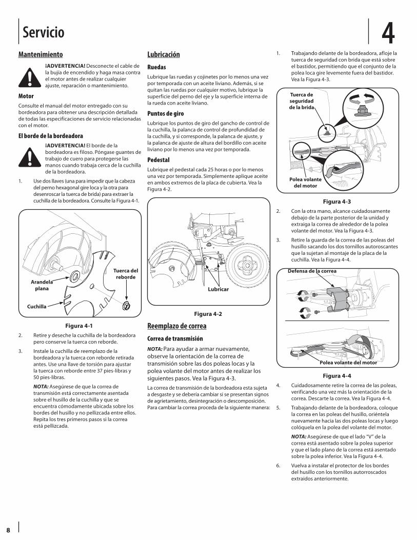
El borde de la bordeadora¡ADVERTENCIA! El borde de la bordeadora es filoso. Póngase guantes de trabajo de cuero para protegerse las manos cuando trabaja cerca de la cuchilla de la bordeadora.
1. Use dos llaves (una para impedir que la cabeza del perno hexagonal gire loca y la otra para desenroscar la tuerca de brida) para extraer la cuchilla de la bordeadora. Consulte la Figura 4-1.
Tuerca del reborde
Cuchilla
Arandela plana
Figura 4-12. Retire y deseche la cuchilla de la bordeadora
pero conserve la tuerca con reborde.
3. Instale la cuchilla de reemplazo de la bordeadora y la tuerca con reborde retirada antes. Use una llave de torsión para ajustar la tuerca con reborde entre 37 pies-libras y 50 pies-libras.
NOTA: Asegúrese de que la correa de transmisión está correctamente asentada sobre el husillo de la cuchilla y que se encuentra cómodamente ubicada sobre los bordes del husillo y no pellizcada entre ellos. Repita los tres primeros pasos si la correa está pellizcada.
LubricaciónRuedasLubrique las ruedas y cojinetes por lo menos una vez por temporada con un aceite liviano. Además, si se quitan las ruedas por cualquier motivo, lubrique la superficie del perno del eje y la superficie interna de la rueda con aceite liviano.
Puntos de giroLubrique los puntos de giro del gancho de control de la cuchilla, la palanca de control de profundidad de la cuchilla, y si corresponde, la palanca de ajuste, y la palanca de ajuste de altura del bordillo con aceite liviano por lo menos una vez por temporada.
PedestalLubrique el pedestal cada 25 horas o por lo menos una vez por temporada. Simplemente aplique aceite en ambos extremos de la placa de cubierta. Vea la Figura 4-2.
Lubricar
Figura 4-2
Reemplazo de correaCorrea de transmisión
NOTA: Para ayudar a armar nuevamente, observe la orientación de la correa de transmisión sobre las dos poleas locas y la polea volante del motor antes de realizar los siguientes pasos. Vea la Figura 4-3.
La correa de transmisión de la bordeadora esta sujeta a desgaste y se debería cambiar si se presentan signos de agrietamiento, desintegración o descomposición. Para cambiar la correa proceda de la siguiente manera:
1. Trabajando delante de la bordeadora, afloje la tuerca de seguridad con brida que está sobre el bastidor, permitiendo que el conjunto de la polea loca gire levemente fuera del bastidor. Vea la Figura 4-3.
Tuerca de seguridadde la brida
Polea volantedel motor
Figura 4-32. Con la otra mano, alcance cuidadosamente
debajo de la parte posterior de la unidad y extraiga la correa de alrededor de la polea volante del motor. Vea la Figura 4-3.
3. Retire la guarda de la correa de las poleas del husillo sacando los dos tornillos autoroscantes que la sujetan al montaje de la placa de la cuchilla. Vea la Figura 4-4.
Polea volante del motor
Defensa de la correa
Figura 4-44. Cuidadosamente retire la correa de las poleas,
verificando una vez más la orientación de la correa. Descarte la correa. Vea la Figura 4-4.
5. Trabajando delante de la bordeadora, coloque la correa en las poleas del husillo, oriéntela nuevamente hacia las dos poleas locas y luego colóquela en la polea del volante del motor.
NOTA: Asegúrese de que el lado “V” de la correa está asentado sobre la polea superior y que el lado plano de la correa está asentado sobre la polea inferior. Vea la Figura 4-4.
6. Vuelva a instalar el protector de los bordes del husillo con los tornillos autorroscados extraidos anteriormente.

9Sección 4 — Servicio
7. Asegúrese de que la correa de transmisión está sobre la polea volante del motor y las poleas locas, y vuelva a ajustar la tuerca de seguridad con brida que se encuentra en la parte superior del bastidor.
NOTA: Asegúrese de que la correa de transmisión está correctamente asentada y que se encuentra cómodamente ubicada sobre los bordes del husillo y no pellizcada entre ellos. Repita los tres primeros pasos si la correa está pellizcada.
¡ADVERTENCIA! Nunca opere la bordeadora sin el protector de la correa de los bordes del husillo en su lugar.
Almacenamiento fuera de temporadaObserve lo siguiente cuando prepare la bordeadora para su almacenamiento prolongado:
1. Limpie y lubrique la unidad minuciosamente como explica la sección de mantenimiento de este manual.
2. Consulte el manual del motor entregado por separado con la bordeadora y lea las instrucciones de almacenamiento del fabricante.
3. Cubra la cuchilla de la bordeadora con grasa para chasis para impedir la oxidación y la corrosión.
Problema Causa Remedio
El motor no arranca 1. El filtro de aire está sucio
2. El motor debe ser cebado
3. El tanque de combustible está vacío
4. Combustible viejo en el tanque de gasolina
5. Se ha desconectado el cable de la bujía.
6. Bujía defectuosa
7. Motor ahogado
1. Consulte el manual del motor enviado junto con su unidad.
2. Empuje el bulbo del cebador dos o tres veces.
3. Llene el tanque con gasolina limpia y fresca.
4. Drene la gasolina y vuelva a llenar el tanque con gasolina limpia y nueva.
5. Conecte el cable de la bujía a la bujía.
6. Limpie, ajuste la separación, o cambie la bujía.
7. Consulte el manual del motor enviado junto con su unidad.
El motor funciona de manera errática
1. El cable de la bujía está flojo
2. Combustible viejo en el tanque de gasolina
3. La ventilación en la tapa del combustible está obstruida
4. Agua o suciedad en el sistema de combustible
5. El filtro de aire está sucio
1. Conecte y ajuste el cable de la bujía.
2. Drene la gasolina y vuelva a llenar el tanque con gasolina limpia y nueva.
3. Despeje la ventilación retirando los residuos.
4. Vacíe el depósito de combustible. Cargue combustible nuevo en el depósito.
5. Consulte el manual del motor enviado junto con su unidad.
El motor recalienta 1. El nivel de aceite del motor está bajo
2. Flujo de aire restringido
3. Filtro de aire está sucio
1. Llene el cárter con aceite adecuado.
2. Limpie el área alrededor y en la parte superior del motor.
3. Consulte el manual del motor enviado junto con su unidad.
Saltos ocasionales(pausas) aalta velocidad
1. La distancia disruptiva de la bujía es muy pequeña. 1. Ajuste la distancia disruptiva. Consulte el manual del motor para conocer las especificaciones de separación.
Funciona mal enmarcha lenta
1. Bujía atorada, averiada o exceso de distancia disruptiva.
2. El filtro de aire está sucio.
1. Reajuste la distancia disruptiva o reemplace la bujía.
2. Consulte el manual del motor enviado junto con su unidad.
Demasiada vibración 1. La cuchilla de la bordeadora está doblada o dañada
2. El husillo de la bordeadora está doblado o dañado
1. Reemplace la cuchilla de la bordeadora.
2. Póngase en contacto con un distribuidor de servicio MTD autorizado.
La correa de transmisión se resbala 1. La correa está gastada o estirada 1. Reemplace la correa de transmisión.
Solución de problemas
4. Almacene la bordeadora en una zona limpia y seca. No la almacene contigua a ningún material corrosivo, como es el fertilizante para césped.
5. Recubra la bordeadora, especialmente cualquier resorte y cojinete, con aceite liviano o aerosol de silicona.
NOTA: Si va a almacenar cualquier tipo de equipo motorizado en un lugar mal ventilado o un galpón metálico, debe tener cuidado de ponerle antioxidante al equipo.

Notas
10