operational issues affecting the practical implementation...
TRANSCRIPT
American Institute of Aeronautics and Astronautics
1
Operational Issues Affecting the Practical Implementation of
Pulsed Detonation Engines
Philip K. Panicker*, Donald R. Wilson† and Frank K. Lu‡ Aerodynamic Research Center (ARC), Department of Mechanical and Aerospace Engineering, Box 19018,
University of Texas at Arlington, Arlington, TX 76019, USA
Pulsed detonation engines are slated to be the engines of the future promising better
efficiencies and high Mach number applications. There are presently many centers of
experimental PDE studies around the world. Most of the studies involve single shot and very
short duration test runs. This paper looks at some of the issues faced by engineers studying
PDEs, including issues that prevent longer duration testing, and offers some solutions that
were developed during several years of PDE study. Some of the concerns investigated
include the possibility of damage to the combustion chamber, auxiliary components,
diagnostic devices, valves, ignition plugs and DDT enhancing devices, such as Shchelkin
spirals, due to the innate extreme conditions of high heat and pressures found in PDEs.
Viable solutions are offered that may help overcome these difficulties. Commercial solenoid
valves and electronic fuel injectors are presented as the means to achieving higher
operational frequencies. In addition, their modularity, low costs and their ability for
precision digital control are clear advantages over heavier, more complex rotary or
mechanical valving systems. Issues concerning data acquisition, such as proper
implementing procedures for pressure transducers and choosing the appropriate sampling
rates are discussed. A common concern during the data acquisition is the management of
large amounts of data. Some simple and cost effective answers are proposed, such as
implementing RAID for computing. EMI is a big concern for engineers in PDE studies
because the instruments and devices used in the laboratories are sources of noise. Several
solutions are pointed out to mitigate the effects of noise on the signals. Noise control should
be looked at proactively during the design stage of the experimental set up because failing to
do so can mean retroactive and sometimes costly modifications to experimental setup.
Finally, some steps to improve safety during PDE studies are presented.
Nomenclature
ADC = Analog to Digital Converter DAQ = Data acquisition system DDT = Deflagration-to-detonation transition DFT = Discrete Fourier Transform EMI = Electro-magnetic interference FFT = Fast Fourier Transform GB = Giga-byte i.d. = Internal Diameter J = Joule k = kilo (103) K = Kelvin m = meter or milli (10-3) (e.g. mJ = milli-Joule) M = Mega (106)
* Graduate Research Associate, Department of Mechanical and Aerospace Engineering, UT Arlington, Student Member AIAA. † Professor, Department of Mechanical and Aerospace Engineering, UT Arlington, Associate Fellow AIAA. ‡ Professor, Department of Mechanical and Aerospace Engineering, UT Arlington, Associate Fellow AIAA.
American Institute of Aeronautics and Astronautics
2
o.d. = Outer Diameter RAID = Redundant Array of Independent/Inexpensive Disks s = Second S/s = Samples per second SCR = Silicon Controlled Rectifier TOF = Time-of-flight TTL = Transistor Transistor Logic
µ = Micro (10-6)
Ω = Ohm
ω = Angular frequency
Introduction
ULSED Detonation Engines offer many advantages over conventional propulsion systems and are widely regarded as the engine system of choice for future military and civilian aircrafts. PDEs do away with the
compressor turbo-machinery because high compression ratios are not required for their operation. This gives them a higher thrust to weight ratio than turbo-jet engines. Also, the level of complexity and price are brought down dramatically. In PDEs the compression is performed by a detonation wave, which compresses and detonates the fuel-oxidizer mixture in the combustion chamber in a constant volume process. Detonation produces higher pressures, temperatures and thus a higher thermodynamic efficiency. The energy released by the detonation process is much higher than that of a deflagration process. Thus, PDEs can deliver improved fuel efficiencies and longer ranges. They can operate in Mach number regimes from 0 to about 51. They can be used in conjunction with other developing technologies, for example the combustor in scram jet engines can be driven in PDE mode. They can be combined with ejectors8 to augment thrust. All of these reasons make the PDE a versatile and cost effective propulsion system unsurpassed in performance. In addition, other applications for PDE are also being looked at including ground based electric power generation in which the PDE output drives a turbine that then drives a generator.
Presently, there are a large number of research studies1, both experimental and computational, on PDEs. In the experimental side, most of the studies are performed on single shot test beds or those whose run times last for very short times, in the range of 10 to 20 s. However, longer test times are required to study technologies that can be applied for flight model engines and for ground based engines. Experimental studies have been carried out on PDEs at the Aerodynamic Research Center of UT Arlington since the late 1990s2-8. The objective of this paper is to outline a few operational issues that were discovered during the tests and to offer solutions to those difficulties so as to improve test results, increase the run times and operating frequencies and widen the scope of study of experimental PDEs.
The PDE cycle consists of the following stages. Tcycle = Tpurge + Tfill + Tignition + Tinduction + Tblowdown. (1)
The frequency of the engine is given by f = 1/ Tcycle. The purging stage and the fuel-oxidizer filling stages are the longest. The purging stage is very important as this stage cools the tube as well as cleans it for a fresh charge. Without this stage, the PDE would suffer a rapid meltdown. Tinduction is the time for the shock wave to reach the end of the tube. (Tinduction is not to be confused with induction zone, found in the ZND detonation wave model, which is the region in between the shock wave and the heat releasing reaction front.) Tblowdown is the thrust producing stage and is very short compared to the filling and purging stages.
A. Solenoid Valves vs. Mechanical Valves
The fastest mechanical valves today are in use in Formula 1 engines. Cosworth, the F1 engine manufacturer, produces V10 engines that run at 20,000 rpm. That means that the cam operated valves open and close 10,000 times a minute or 167 times a second. Such valving systems have many moving parts, increasing the complexity of the engines. The trend today in the automobile industry is to move to electronic injection systems, using solenoid controlled valves. Most automobiles in the present day use fuel injection. More and more diesel vehicles today use electronic injectors with built in pressure boosters, which boost the injection pressure to as high as 2000 bar. Such a high pressure is required to spray the fuel directly into the engine, right after the compression stroke, driving the piston downward. Modern gasoline injectors also inject directly in to the engine at high pressures. Moreover, valves for alternative automotive fuels, such as propane, methane, LPG, ethanol and increasingly, hydrogen, are presently available off the shelf. These valves can be easily adapted for use in PDEs. Electronic valves are very fast acting (ms or fractional ms reaction times) and can be precisely controlled by a TTL signal from a computer at high speeds up
P

American Institute of Aeronautics and Astronautics
3
to a few hundred operations per second. Since they are available commercially, their specifications are obtainable from the manufacturer and they are easily replaceable. That also means that they have already been field tested by the automotive industry and it will be easier to find necessary services.
Rotary valves are leaky, and cannot operate at high pressures. They are difficult to time precisely and require a sensor, such as a magnetic pickup or a photo-detector, to detect the position of the valve or cam in order to fire the ignition. Many PDE tests conducted at the ARC with rotary valves2, 3, 4
that were assembled in house did not produce satisfactory results. The transmission belts slip and the valves lose synchronicity quickly. This leads to improper filling and misfiring of the PDE. Also, since the PDE combustion chamber is filled from the back end and due to the lower operating pressures of the rotary valves, the PDE could not be filled to the brim at higher frequencies. It is difficult to achieve proper stoichiometry or the required equivalence ratio using rotary valves. In the laboratory, rotary valves are usually run by means of an electric motor, which is a source of EMI and mechanical vibrations. Due to these reasons, the decision was made to move away from rotary valves and to build PDE platforms using solenoid valves for all further testing.
How to increase frequency: Most PDE designs employ valves located at the back end of the tube. Thus, a long tube requires longer times to fill and purge, setting a ceiling on the maximum operation frequency and consequently on thrust, as thrust is directly proportional to the frequency. To decrease fill times, high supply pressures are required. This is not practical for the following reasons: Mechanical valves will experience severe leaking due to failure of seals. Certain fuels have low liquefaction pressures, e.g., propane liquefies at close to 10 bar at room temperature, setting an upper limit to the maximum operable pressure. Solenoid valves cannot operate beyond their maximum rated pressures. Higher pressures require more energy being wasted to pre-compress the gases, which is not practical for flight weight models. Therefore, a much simpler way to
Figure 1. By placing injection ports along the length of the PDE combustion chamber, the fill time of the
PDE can be shorted, thereby, increasing the frequency. The fill time of each individual valve in the array
is also shortened. By having two or more sets of valves supplying the fuel-air mixture and purge air, and
by staggering their opening times, the frequency can be doubled.
Table 1. Lower and higher explosive
limits (LEL and HEL) and ignition
temperatures (IT) for mixtures of various
substances with air at 1 atm.
Substance LEL (%)
HEL (%)
IT (˚C)
Acetylene 2.5 100 305
Avgas 100 1.2 7 433
Benzene 1.2 7.8 498
Butane 1.9 8.5 287
Diesel 0.6 7.5
Ethane 3 12.5 472
Ethanol 3.3 19 363
Ethylene 2.7 36 450
Gasoline 1.4 7.6
Heptane 1.05 6.7 204
Hexane 1.1 7.5 225
Hydrogen 4 74 572
JP-10 245
JP-4 1.3 8 246
JP-5 0.6 4.6 241
JP-7 0.6 4.6 241
JP-8 0.6 4.7 238
Kerosene 0.6 4.9
Methane 5 15 537
Octane 1 6.5 206
Pentane 1.4 8 260
Propane 2.1 9.5 450

American Institute of Aeronautics and Astronautics
4
increase operation frequency of PDEs is to increase the number of filling ports and valves along the length of the tube. Since the electronic valves can all be opened simultaneously from one control signal, low filling pressures are sufficient for even long tubes.
Although solenoid valves are fast, they do have finite reaction times for opening and closing, ranging from a fraction of a ms to a few ms. Another problem encountered is the residual magnetism that lingers in the steel body of the valve even after the power has been cut off, causing a delay in the closing of the valves. Therefore, beyond a certain frequency, solenoid valves tend to chatter. This can be overcome by using multiple sets of valves, whose operation can be staggered in time, as shown in Fig. 1. By changing the duty cycle of the valves, while keeping the frequency constant, and by introducing a time delay between sets of valves, very high frequencies can be achieved.
Since the volume of fuel required for forming a detonable mixture is much lesser than the volume of air (see Table 1)11, smaller sized valves or fewer number of valves can be used for the fuel service compared to the number of air/oxygen service valves. Also, the air valves can be used twice within a time period, once for supplying air to mix with the fuel and secondly, during the purge stage of the cycle. Thus, the number of valves can be reduced by tactically designing the valve timings as seen in Fig. 2.
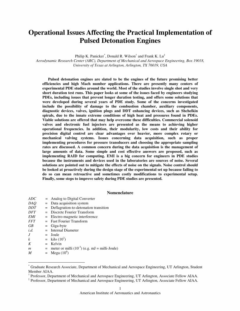
B. Shchelkin Spirals From various studies at the ARC2, 3 as well as elsewhere, the Shchelkin spiral has proven to be most effective in
inducing DDT in relatively short run up distances. In previous studies at the ARC on PDEs running propane and oxygen mixtures in a 25 mm i.d. tube at 10 Hz, circa June 20052, it was found that spirals with 55% blockage ratio are the most effective. Shchelkin spirals have a few shortcomings that may hinder their implementation in a long duration test set up. The spirals have to withstand tremendous thermal and pressure loadings. During the aforementioned tests, it was found that all the spirals were damaged after 10 to 20 seconds of run time. The high temperatures weaken the metal and the high pressure compresses the helix after which it may melt and fuse together. In some instances, the spiral disintegrates and is expelled at high speeds from the tube. The spirals used in the study were made of stainless steel and initially does not exhibit magnetism. However, the residue of the springs that remained after the tests were attracted by a magnet when introduced close by. This attests to the remarkable amounts of heat generated inside PDE engines, which can cause the steel alloy to revert back into iron. The combustion chamber where the spiral is installed becomes red hot after a few seconds of run time, as this is the location of the
Figure 2. A schematic of the TTL control signals for injection valve timing is shown with duty cycles and
time delays adjusted for two sets of valves. Within one clock pulse each set of valves open and close only
once, but by using two sets of valves, the operational frequency of the PDE is doubled. The ignition signal
is given right after the fill valves close at the beginning of Td0. The detonation, combustion and exhaust
processes occur during Td0.
American Institute of Aeronautics and Astronautics
5
tube that experiences the highest thermal and pressure stresses. In addition to these drawbacks, Shchelkin spirals do cause drag, but the rapid DDT more than makes up for that.
Subsequent studies were conducted in December 2005 at the ARC, on a PDE platform using propane and oxygen mixtures in a combustion chamber with an i.d. of 25 mm and operating at 10 to 25Hz, in which various other DDT enhancing devices were tested for their efficacy, in addition to Shchelkin spirals. The other devices tested included grooved metal sleeves, slotted sleeves and converging diverging nozzles (30˚ and 15˚ individually and in tandem). Once again, it was revealed that the Shchelkin spiral was the most successful DDT inducing device. This success is ascribed to the smooth undulations of the spiral which aid in turbulent mixing, unlike the sharp corners and dead spaces found in the grooved sleeves. The performance of CD nozzles also fell below expectations. The nozzles seem to choke off the flow rather than induce turbulent mixing.
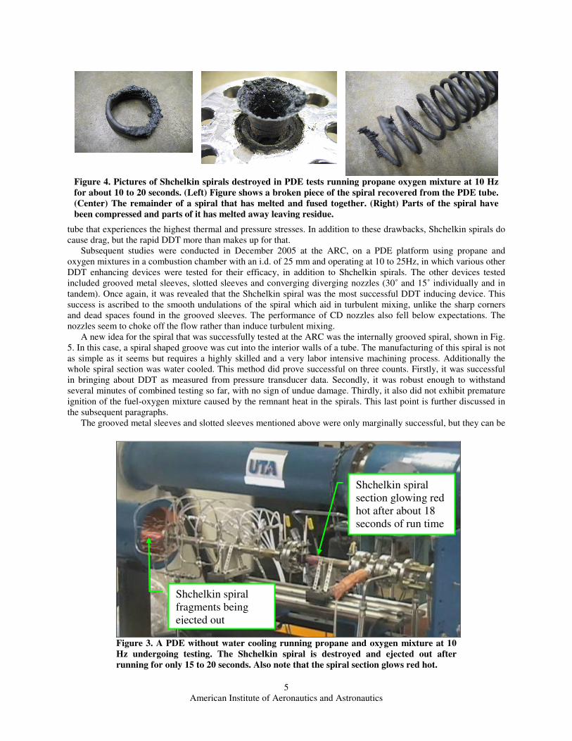
A new idea for the spiral that was successfully tested at the ARC was the internally grooved spiral, shown in Fig. 5. In this case, a spiral shaped groove was cut into the interior walls of a tube. The manufacturing of this spiral is not as simple as it seems but requires a highly skilled and a very labor intensive machining process. Additionally the whole spiral section was water cooled. This method did prove successful on three counts. Firstly, it was successful in bringing about DDT as measured from pressure transducer data. Secondly, it was robust enough to withstand several minutes of combined testing so far, with no sign of undue damage. Thirdly, it also did not exhibit premature ignition of the fuel-oxygen mixture caused by the remnant heat in the spirals. This last point is further discussed in the subsequent paragraphs.
The grooved metal sleeves and slotted sleeves mentioned above were only marginally successful, but they can be
Figure 4. Pictures of Shchelkin spirals destroyed in PDE tests running propane oxygen mixture at 10 Hz
for about 10 to 20 seconds. (Left) Figure shows a broken piece of the spiral recovered from the PDE tube.
(Center) The remainder of a spiral that has melted and fused together. (Right) Parts of the spiral have
been compressed and parts of it has melted away leaving residue.
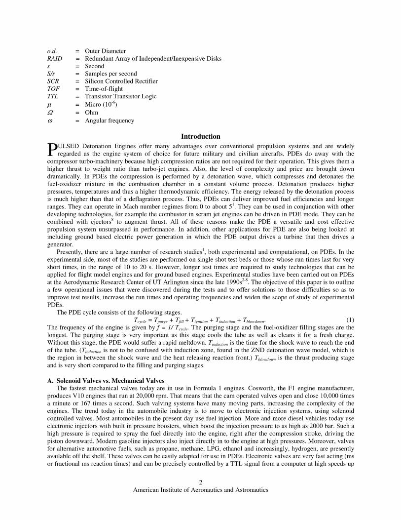
Figure 3. A PDE without water cooling running propane and oxygen mixture at 10
Hz undergoing testing. The Shchelkin spiral is destroyed and ejected out after
running for only 15 to 20 seconds. Also note that the spiral section glows red hot.
Shchelkin spiral fragments being ejected out
Shchelkin spiral section glowing red hot after about 18 seconds of run time
American Institute of Aeronautics and Astronautics
6
modified to yield better results by removing sharp edges and adjusting their dimensions (pitch, i.d., o.d., etc.) to suit the cellular structure of the fuel-oxidizer mixture. The sleeve spiral is a useful concept because of its modularity. The sleeves are mounted onto flanges making them easy to remove and install into the detonation chamber. Thus, for a PDE engine in long duration service, a protocol might be set whereby the sleeve spirals may be replaced after a set amount of operating hours, just like engine parts are replaced after every few thousand miles in automobiles, or flight hours in aircrafts.
Another concept that has not been implemented yet is to fashion a spiral out of hollow thick walled steel tubing through which water or coolant can be continuously pumped at high pressures. This method
requires more intricate fittings and joints that will allow liquid to be injected through the walls of the PDE while it is running. This method can only be put into operation in PDEs having larger internal diameters because only moderate sized tubes (larger than 0.5 cm o.d.) can be used for this purpose, as thin walled tubes of small diameters will not last long.
C. Water Cooling of PDE
It is clearly important to have a cooling system for the PDE, to protect the combustion chamber, valves, diagnostic instruments and other components from damage and also so that its run time may be increased. A simple way to achieve the cooling for ground based test engines is to devise a water jacket around the tubes. For laboratory based studies, the cooling system need not be of a re-circulating type, which will require heat exchangers. Fresh cool water can be brought in and circulated through the coolant cavities and then the exhaust warm water can be streamed out into the drains. The section of the combustion tube housing the Shchelkin spiral will need high flow rates of cooling water, as this is a region that experiences high temperatures and pressures. Long duration PDEs, in which large amounts of heat will be generated continuously, will require a high pressure pump to move larger amounts of water or coolant through the cooling cavities, in order to sustain the necessary heat transfer rates. The thumb rule is to pump water at a velocity of 50 ft/s for best convective heat transfer results.
Higher operation frequencies mean greater heat generation which necessitates elevated heat transfer rates to cool the detonation chamber and consequently larger amounts of coolant mass flow. The PDE purge (Tpurge) process will have to be extended also to account for the increased heat generation. The purge process does not produce thrust and increasing the purging time reduces engine output and efficiency. But this may be a small price to pay for higher frequencies, which inherently have higher thrust. In a practical air-breathing aircraft engine, several PDE chambers can be operating simultaneously out of phase with each other, such that at least one PDE chamber is in the purging stage at any given time. This concept is similar to that of internal combustion engines with many cylinders, each one out of synchronization with the others.
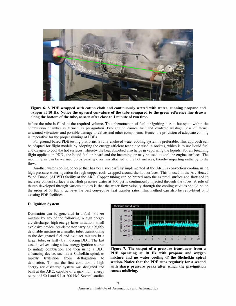
If water cooling is not implemented during the design stage, it can be applied retroactively to the external parts of the PDE tubes, with tolerable effectiveness. However, it may not deliver satisfactory results for prolonged tests. For the PDE tests at the ARC, one method of cooling developed included wrapping the tubes with a cloth that was constantly wetted with running water. Initially, strips of ceramic fiber textiles, capable of withstanding temperatures as high as 1600˚ C, were wrapped around the PDE tubes and continuously doused with water. However, the ceramic cloths do not hold water effectively, and the fibers unravel easily. Therefore, it was replaced with common cotton cloth, such as the type used in athletic socks. This proved to be much more effective for short runs lasting about 20 seconds to a minute. A large amount of steam is generated during the tests. When the run time is increased to over a minute, however, the tubes suffered deformation and it was seen to slowly bow upwards. However, the Shchelkin spirals were not adequately cooled and were all destroyed in the tests.
Water cooling for the Shchelkin spiral is particularly important not just because it is the hottest part of the combustion chamber, but also because the hot Shchelkin spiral can cause the fuel and oxidizer mixture to ignite
Figure 5. Schematic of a PDE combustion chamber with
internal spiral grooves in lieu of a Shchelkin spiral. The whole
assembly is also water cooled with entry and exit ports for
water on the flanges.
American Institute of Aeronautics and Astronautics
7
before the tube is filled to the required volume. This phenomenon of fuel-air igniting due to hot spots within the combustion chamber is termed as pre-ignition. Pre-ignition causes fuel and oxidizer wastage, loss of thrust, unwanted vibrations and possible damage to valves and other components. Hence, the provision of adequate cooling is imperative for the proper running of PDEs.
For ground based PDE testing platforms, a fully enclosed water cooling system is preferable. This approach can be adapted for flight models by adopting the energy efficient technique used in rockets, which is to use liquid fuel and oxygen to cool the hot surfaces, whereby the heat absorbed also helps in vaporizing the liquids. For air breathing flight application PDEs, the liquid fuel on board and the incoming air may be used to cool the engine surfaces. The incoming air can be warmed up by passing over fins attached to the hot surfaces, thereby imparting enthalpy to the flow.
Another water cooling concept that has been successfully implemented at the ARC is convection cooling using high pressure water injection through copper coils wrapped around the hot surfaces. This is used in the Arc Heated Wind Tunnel (AHWT) facility at the ARC. Copper tubing can be brazed onto the external surface and flattened to increase contact surface area. High pressure water at 300 psi is continuously injected through the tubes. A rule of thumb developed through various studies is that the water flow velocity through the cooling cavities should be on the order of 50 ft/s to achieve the best convective heat transfer rates. This method can also be retro-fitted onto existing PDE facilities.
D. Ignition System
Detonation can be generated in a fuel-oxidizer mixture by any of the following: a high energy arc discharge, high energy laser initiation, small explosive device, pre-detonator carrying a highly detonable mixture in a smaller tube, transitioning to the designated fuel and oxidizer mixture in a larger tube, or lastly by inducing DDT. The last case, involves using a low energy ignition source to initiate combustion and then using a DDT enhancing device, such as a Shchelkin spiral, to rapidly transition from deflagration to detonation. To test the first condition, a high energy arc discharge system was designed and built at the ARC, capable of a maximum energy output of 50 J and 5 J at 200 Hz7. Several studies
Figure 6. A PDE wrapped with cotton cloth and continuously wetted with water, running propane and
oxygen at 10 Hz. Notice the upward curvature of the tube compared to the green reference line drawn
along the bottom of the tube, as seen after close to 1 minute of run time.
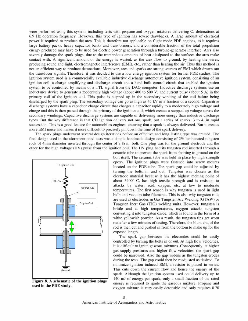
Figure 7. The output of a pressure transducer from a
PDE operating at 10 Hz with propane and oxygen
mixture and no water cooling of the Shchelkin spiral
section. Notice that the PDE runs regularly for a second
with sharp pressure peaks after which the pre-ignition
causes misfiring.
American Institute of Aeronautics and Astronautics
8
were performed using this system, including tests with propane and oxygen mixtures delivering CJ detonations at 6.9 Hz operation frequency. However, this type of ignition has severe drawbacks. A large amount of electrical power is required to produce the arcs. This is therefore not applicable on flight mode PDE engines, as it requires large battery packs, heavy capacitor banks and transformers, and a considerable fraction of the total propulsion energy produced may have to be used for electric power generation through a turbine-generator interface. Arcs also severely damage the spark plugs, due to the tremendous amounts of heat dissipated to the surfaces the arcs make contact with. A significant amount of the energy is wasted, as the arcs flow to ground, by heating the wires, producing sound and light, electromagnetic interference (EMI), etc., rather than heating the air. Thus this method is not an efficient way to produce detonations. Moreover, arcs and sparks are strong sources of EMI which drown out the transducer signals. Therefore, it was decided to use a low energy ignition system for further PDE studies. The ignition system used is a commercially available inductive discharge automotive ignition system, consisting of an ignition coil, a charge amplifying and discharge circuit and a hand built control circuit that enabled the ignition system to be controlled by means of a TTL signal from the DAQ computer. Inductive discharge systems use an inductance device to generate a moderately high voltage (about 400 to 500 V) and current pulse (about 5 A) in the primary coil of the ignition coil. This pulse is stepped up in the secondary winding of the coil before being discharged by the spark plug. The secondary voltage can go as high as 45 kV in a fraction of a second. Capacitive discharge systems have a capacitor charge circuit that charges a capacitor rapidly to a moderately high voltage and charge and this is then passed through the primary of the ignition coil, which creates a stepped up voltage across the secondary windings. Capacitive discharge systems are capable of delivering more energy than inductive discharge types. But the key difference is that CD ignition delivers not one spark, but a series of sparks, 3 to 4, in rapid succession. This is a good feature for automobiles engines, ensuring that a spark is always delivered. But it creates more EMI noise and makes it more difficult to precisely pin down the time of the spark delivery.
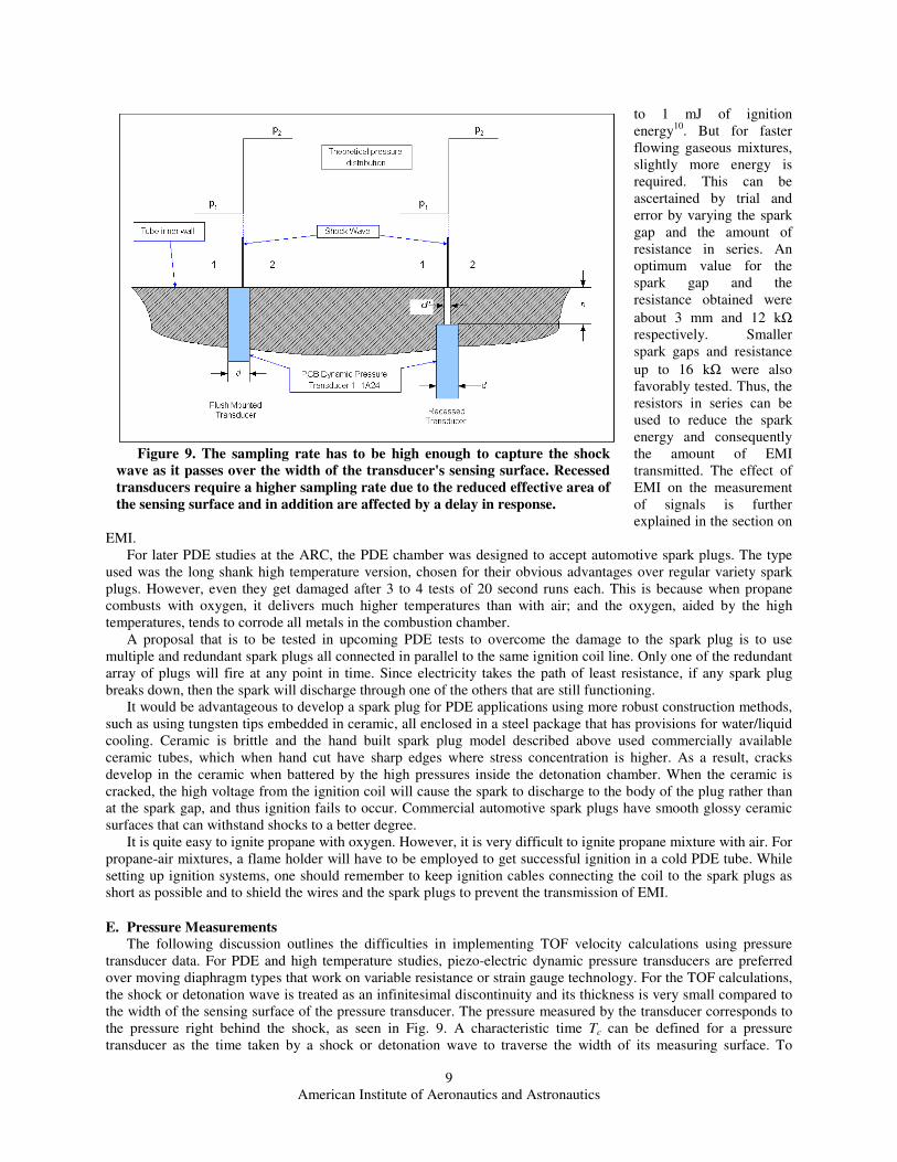
The spark plugs underwent several design iterations before an effective and long lasting type was created. The final design used in the aforementioned tests was a simple handmade design consisting of 2% lanthanated tungsten rods of 4mm diameter inserted through the center of a ½ in. bolt. One plug was for the ground electrode and the other for the high voltage (HV) pulse from the ignition coil. The HV plug had its tungsten rod inserted through a
ceramic tube to prevent the spark from shorting to ground on the bolt itself. The ceramic tube was held in place by high strength epoxy. The ignition plugs were fastened into screw mounts located on the PDE tube. The spark gap could be adjusted by turning the bolts in and out. Tungsten was chosen as the electrode material because it has the highest melting point of about 3400˚ C, has high tensile strength and is resistant to attacks by water, acid, oxygen, etc. at low to moderate temperatures. The first reason is why tungsten is used in light bulb and vacuum tube filaments. This is also why tungsten rods are used as electrodes in Gas Tungsten Arc Welding (GTAW) or Tungsten Inert Gas (TIG) welding units. However, tungsten is brittle and at high temperatures, oxygen attacks tungsten converting it into tungsten oxide, which is found in the form of a white yellowish powder. As a result, the tungsten tips get worn out after a few minutes of testing. Therefore, the blunt end of the rod is then cut and pushed in from the bottom to make up for the exposed length.
The spark gap between the electrodes could be easily controlled by turning the bolts in or out. At high flow velocities, it is difficult to ignite gaseous mixtures. Consequently, at higher gas supply pressures and higher flow velocities, the spark gap could be narrowed. Also the gap widens as the tungsten erodes during the tests. The gap could then be readjusted as desired. To minimize ignition induced EMI, a resistor is placed in series. This cuts down the current flow and hence the energy of the spark. Although the ignition system used could delivery up to 140 mJ of energy per spark, only a small fraction of the rated energy is required to ignite the gaseous mixture. Propane and oxygen mixture is very easily detonable and only requires 0.20
Figure 8. A schematic of the ignition plugs
used in the PDE study.
American Institute of Aeronautics and Astronautics
9
to 1 mJ of ignition energy10. But for faster flowing gaseous mixtures, slightly more energy is required. This can be ascertained by trial and error by varying the spark gap and the amount of resistance in series. An optimum value for the spark gap and the resistance obtained were
about 3 mm and 12 kΩ respectively. Smaller spark gaps and resistance
up to 16 kΩ were also favorably tested. Thus, the resistors in series can be used to reduce the spark energy and consequently the amount of EMI transmitted. The effect of EMI on the measurement of signals is further explained in the section on
EMI. For later PDE studies at the ARC, the PDE chamber was designed to accept automotive spark plugs. The type
used was the long shank high temperature version, chosen for their obvious advantages over regular variety spark plugs. However, even they get damaged after 3 to 4 tests of 20 second runs each. This is because when propane combusts with oxygen, it delivers much higher temperatures than with air; and the oxygen, aided by the high temperatures, tends to corrode all metals in the combustion chamber.
A proposal that is to be tested in upcoming PDE tests to overcome the damage to the spark plug is to use multiple and redundant spark plugs all connected in parallel to the same ignition coil line. Only one of the redundant array of plugs will fire at any point in time. Since electricity takes the path of least resistance, if any spark plug breaks down, then the spark will discharge through one of the others that are still functioning.
It would be advantageous to develop a spark plug for PDE applications using more robust construction methods, such as using tungsten tips embedded in ceramic, all enclosed in a steel package that has provisions for water/liquid cooling. Ceramic is brittle and the hand built spark plug model described above used commercially available ceramic tubes, which when hand cut have sharp edges where stress concentration is higher. As a result, cracks develop in the ceramic when battered by the high pressures inside the detonation chamber. When the ceramic is cracked, the high voltage from the ignition coil will cause the spark to discharge to the body of the plug rather than at the spark gap, and thus ignition fails to occur. Commercial automotive spark plugs have smooth glossy ceramic surfaces that can withstand shocks to a better degree.
It is quite easy to ignite propane with oxygen. However, it is very difficult to ignite propane mixture with air. For propane-air mixtures, a flame holder will have to be employed to get successful ignition in a cold PDE tube. While setting up ignition systems, one should remember to keep ignition cables connecting the coil to the spark plugs as short as possible and to shield the wires and the spark plugs to prevent the transmission of EMI.
E. Pressure Measurements
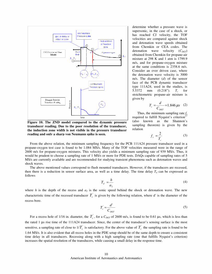
The following discussion outlines the difficulties in implementing TOF velocity calculations using pressure transducer data. For PDE and high temperature studies, piezo-electric dynamic pressure transducers are preferred over moving diaphragm types that work on variable resistance or strain gauge technology. For the TOF calculations, the shock or detonation wave is treated as an infinitesimal discontinuity and its thickness is very small compared to the width of the sensing surface of the pressure transducer. The pressure measured by the transducer corresponds to the pressure right behind the shock, as seen in Fig. 9. A characteristic time Tc can be defined for a pressure transducer as the time taken by a shock or detonation wave to traverse the width of its measuring surface. To
Figure 9. The sampling rate has to be high enough to capture the shock
wave as it passes over the width of the transducer's sensing surface. Recessed
transducers require a higher sampling rate due to the reduced effective area of
the sensing surface and in addition are affected by a delay in response.
American Institute of Aeronautics and Astronautics
10
determine whether a pressure wave is supersonic, in the case of a shock, or has reached CJ velocity, the TOF velocities are compared against shock and detonation wave speeds obtained from Chemkin or CEA codes. The detonation wave velocity (CDET) obtained from Chemkin for propane-air mixture at 298 K and 1 atm is 1799.9 m/s, and for propane-oxygen mixture at the same conditions is 2358.6 m/s. Consider an over driven case, where the detonation wave velocity is 3000 m/s. The diameter (d) of the sensor face of the PCB dynamic transducer type 111A24, used in the studies, is 5.5372 mm (0.218”). Tc for stoichiometric propane-air mixture is given by
sC
dT
DET
c µ846.1== (2)
Thus, the minimum sampling rate fs required to fulfill Nyquist’s criterion17 (also known as the Shannon’s sampling theorem) is given by the relation
c
sT
f2
= (3)
From the above relation, the minimum sampling frequency for the PCB 111A24 pressure transducer used in a propane-oxygen test case is found to be 1.084 MS/s. Many of the TOF velocities measured were in the range of 2600 m/s for propane-oxygen mixtures. This velocity also yields a minimum sampling rate of 939 MS/s. Thus, it would be prudent to choose a sampling rate of 1 MS/s or more for PDE tests. DAQs capable of sampling rates of 5 MS/s are currently available and are recommended for studying transient phenomena such as detonation waves and shock waves.
The above mentioned values correspond to flush mounted transducers. However, if the transducers are recessed, then there is a reduction in sensor surface area, as well as a time delay. The time delay Td can be expressed as follows
2a
hTd = (4)
where h is the depth of the recess and a2 is the sonic speed behind the shock or detonation wave. The new
characteristic time of the recessed transducer '
cT is given by the following relation, where d’ is the diameter of the
recess bore.
DET
cC
dT
'' = (5)
For a recess hole of 1/16 in. diameter, the '
cT , for a CDET of 2600 m/s, is found to be 0.61 µs, which is less than
the rated 1 µs rise time of the 111A24 transducer. Since, the center of the transducer’s sensing surface is the most
sensitive, a sampling rate of close to 1/'
cT is satisfactory. For the above value of '
cT the sampling rate is found to be
1.64 MS/s. It is also evident that all recess holes in the PDE setup should be of the same depth to ensure a consistent time delay in all transducers. Recessing along with a high sampling rate (one that fulfills Nyquist’s criterion) increases the spatial resolution of the transducers, while causing a small delay in the response time.
Figure 10. The ZND model compared to the dynamic pressure
transducer reading. Due to the poor resolution of the transducer,
the induction zone width is not visible in the pressure transducer
reading and only a sharp von Neumann spike is seen.
American Institute of Aeronautics and Astronautics
11
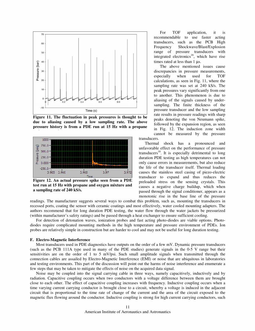
For TOF application, it is recommendable to use faster acting transducers, such as the PCB High Frequency Shockwave/Blast/Explosion range of pressure transducers with integrated electronics18, which have rise
times rated at less than 1 µs. The above mentioned issues cause
discrepancies in pressure measurements, especially when used for TOF calculations, as seen in Fig. 11, where the sampling rate was set at 240 kS/s. The peak pressures vary significantly from one to another. This phenomenon is due to aliasing of the signals caused by under-sampling. The finite thickness of the pressure transducer and the low sampling rate results in pressure readings with sharp peaks denoting the von Neumann spike, followed by the expansion region, as seen in Fig. 12. The induction zone width cannot be measured by the pressure
transducers. Thermal shock has a pronounced and
unfavorable effect on the performance of pressure transducers18. It is especially detrimental to long duration PDE testing as high temperatures can not only cause errors in measurements, but also reduce the life of the transducer itself. Thermal loading causes the stainless steel casing of piezo-electric transducer to expand and thus reduces the preloaded stress on the sensing crystals. This causes a negative charge buildup, which when passed through the signal conditioner, appears as a monotonic rise in the base line of the pressure
readings. The manufacturer suggests several ways to combat this problem, such as, mounting the transducers in recessed ports, coating the sensor with ceramic coatings and most effectively, water cooled mounting adapters. The authors recommend that for long duration PDE testing, the water flow through the water jackets be pressurized (within manufacturer’s safety ratings) and be passed through a heat exchanger to ensure sufficient cooling.
For detection of detonation waves, ionization probes and fast acting photo-diodes are viable options. Photo-diodes require complicated mounting methods in the high temperature and pressure environment of PDEs. Ion probes are relatively simple in construction but are harder to cool and may not be useful for long duration testing.
F. Electro-Magnetic Interference
Most transducers used in PDE diagnostics have outputs on the order of a few mV. Dynamic pressure transducers (such as the PCB 111A type used in many of the PDE studies) generate signals in the 0-5 V range but their sensitivities are on the order of 1 to 5 mV/psi. Such small amplitude signals when transmitted through the connection cables are assailed by Electro-Magnetic Interference (EMI) or noise that are ubiquitous in laboratories and testing environments. This part of the discussion will point out the harms of noise interference and enumerate a few steps that may be taken to mitigate the effects of noise on the acquired data signal.
Noise may be coupled into the signal carrying cable in three ways, namely capacitively, inductively and by radiation. Capacitive coupling occurs when two conductors with a voltage difference between them are brought close to each other. The effect of capacitive coupling increases with frequency. Inductive coupling occurs when a time varying current carrying conductor is brought close to a circuit, whereby a voltage is induced in the adjacent circuit that is proportional to the time rate of change of the current and the area of the circuit exposed to the magnetic flux flowing around the conductor. Inductive coupling is strong for high current carrying conductors, such
Figure 12. An actual pressure spike seen from a PDE
test run at 15 Hz with propane and oxygen mixture and
a sampling rate of 240 kS/s.
Figure 11. The fluctuation in peak pressures is thought to be
due to aliasing caused by a low sampling rate. The above
pressure history is from a PDE run at 15 Hz with a propane
and oxygen mixture.
American Institute of Aeronautics and Astronautics
12
as power cables. Both capacitive and inductive coupling are considered near field coupling, as their effects fall off with distance and are felt only within a quarter wavelength distance. The quarter wavelength is taken as the demarcation between near field coupling and far field or radiation coupling. It is
obtained by the relation given below, where λ is
wavelength, c is the velocity of light and ν is the frequency.
ν
λ
44
c= (6)
For supply line frequency of 50 Hz, the quarter wavelength is 1500 km (940 mi) and for 60 Hz line frequency, the corresponding value is 1250 km (780 mi), although beyond distances of 1 m the effects are negligible for standard supply voltages (120 V or 240V) and moderate currents (1 A). At 100 kHz, the quarter wavelength is 750 m, whereas at 10 MHz, the corresponding value is 7.5 m. If the distance between the source and the affected circuit is greater than the quarter wavelength, it can be treated as radiation coupling only.
The answer to the near field coupling problem is to cover the emitting or receiving conductor, or both,
with a low resistance shielding. On the transmitting conductor, the shield should be connected to the ground of the source, such as a power supply; while for the receiving conductor, the shield should be connected to the ground of the circuit. For low frequency inductive coupling (<100 kHz), ferro-magnetic material may be utilized as shielding. Magnetic material, such as iron, steel, mu-metal, etc., can be used to provide a path for the magnetic fields around inductive devices. By creating a housing made of magnetic materials around sensitive areas, such as connection points, noise can be prevented from coupling to the connectors.
Some near field noise generators are listed below. Power transformers are a big source of inductive noise. Locate all sensitive equipment, DAQ components and computers away from large power transformers. If they are required to be close to the laboratory instruments, a magnetic shield should be provided around them, but care must be taken to allow ventilation. Transformers should not be mounted using screws through holes, to metal fixtures that are part of the building’s ground. This causes a current to flow around this loop and can couple back into the primary of the transformer as well as other circuitry connected to the building ground. It is therefore important to insulate the transformer mounting from the metallic fixtures.
Ungrounded AC and DC power supplies are noisier than grounded systems. Switched Mode Power Supplies (SMPS) are used in bench top DC power supplies. These devices generate high frequency square waves as high as 100 kHz which are then rectified and regulated to a smooth DC value. However, the high frequency oscillations along with its harmonics can get transmitted over the supply lines. Some power supplies deliver the hum from the power supply frequency or its harmonics to the instruments, as well as to the ground, as they are tied to the ground through the wall socket terminal. It is therefore important to procure SMPS based systems with good quality built in filters so as not to get high frequency noise on the ground line or capacitively coupled noise on signal lines. Adding isolation transformers on the supply lines of power supplies and AC powered instruments also help them from being infected with noise transmitted through the power lines, as they act like low pass filters. Line filters should be used on all AC powered devices to prevent conducted noise coming in or going out into the power lines. It is also recommendable to use good quality commercially available power distributors, which have built in surge protection, filtering and shielded isolation transformers, for sensitive instruments.
Electric motors create large amounts of noise during operation, as well as sparks in the case of universal motors found in many household appliances, electric drills, etc. It is, therefore, advisable to shield motors and to move them away from sensitive instruments. Use pneumatic motors wherever possible. Relays, contactors, solenoid valves, and other electromagnetic switching devices, generate three kinds of noise: electromagnetic noise that can be radiated as well as inductively coupled due to switching of large currents; magnetic flux leakages around the relay coils; and spark discharge due to the creation of a large change in voltage or current at the moment of switching. Therefore,
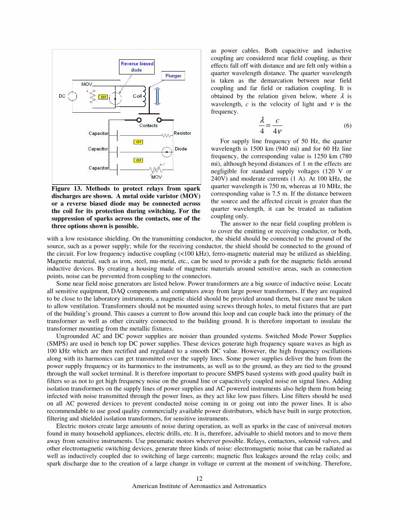
Figure 13. Methods to protect relays from spark
discharges are shown. A metal oxide varistor (MOV)
or a reverse biased diode may be connected across
the coil for its protection during switching. For the
suppression of sparks across the contacts, one of the
three options shown is possible.
American Institute of Aeronautics and Astronautics
13
relays should always be placed in protective shielded enclosures. If possible, use solid state switching devices, such as SCRs (silicon controlled rectifier), transistors, thyristors and electronic relays, whilst ensuring that the switching circuits are housed in shielded boxes.
Every attempt must be made to avoid or suppress sparks. Sparks are caused during fast switching of switches, relays and contactors. Since sparks last for only a fraction of a microsecond, they broadcast a very high frequency signal lasting for a small fraction of time. When this signal is digitized, it can be interpreted as an impulse (Dirac delta) function. Impulse functions have a very narrow width in time, but when the signal is converted to the frequency domain, by means of Discrete Fourier Transform (DFT)17, they are observed to have a flat frequency spectrum across the whole frequency scale (0 to ∞ Hz). Thus spark signals affect the time domain signal, for example, inducing large deviations in TOF calculations, and also cause error in the frequency domain data analysis. Sparks in relays and other switching devices, applied in DC power transmission, can be suppressed by the addition
of capacitors, resistors and diodes. When the relay is cut off quickly, the energy stored in the relay (or solenoid) coil has to be dissipated and this causes a spark across the coil contacts, which may also lead to conflagration of the coil and connected circuits. This can be prevented by adding a diode in reverse to allow the current to neutralize, as shown in Fig. 13. Other methods to suppress sparks are also shown in the same figure, such as connecting a capacitor and resistor across the contacts or alternatively, a capacitor and diode or metal oxide varistor.
There is a spark source that can not be avoided in PDE studies and that is the ignition system. In automotive ignition systems, the cables connecting the ignition coil to the spark plugs have a moderate value of impedance (resistive and inductive) intentionally added to the cables. In addition, the spark plugs have a built in resistance. These measures are taken to cut down the current flowing through the spark plugs and consequently the amount of power radiated out. Without these preventive schemes, the electronic devices in automobiles, such as radios, engine control
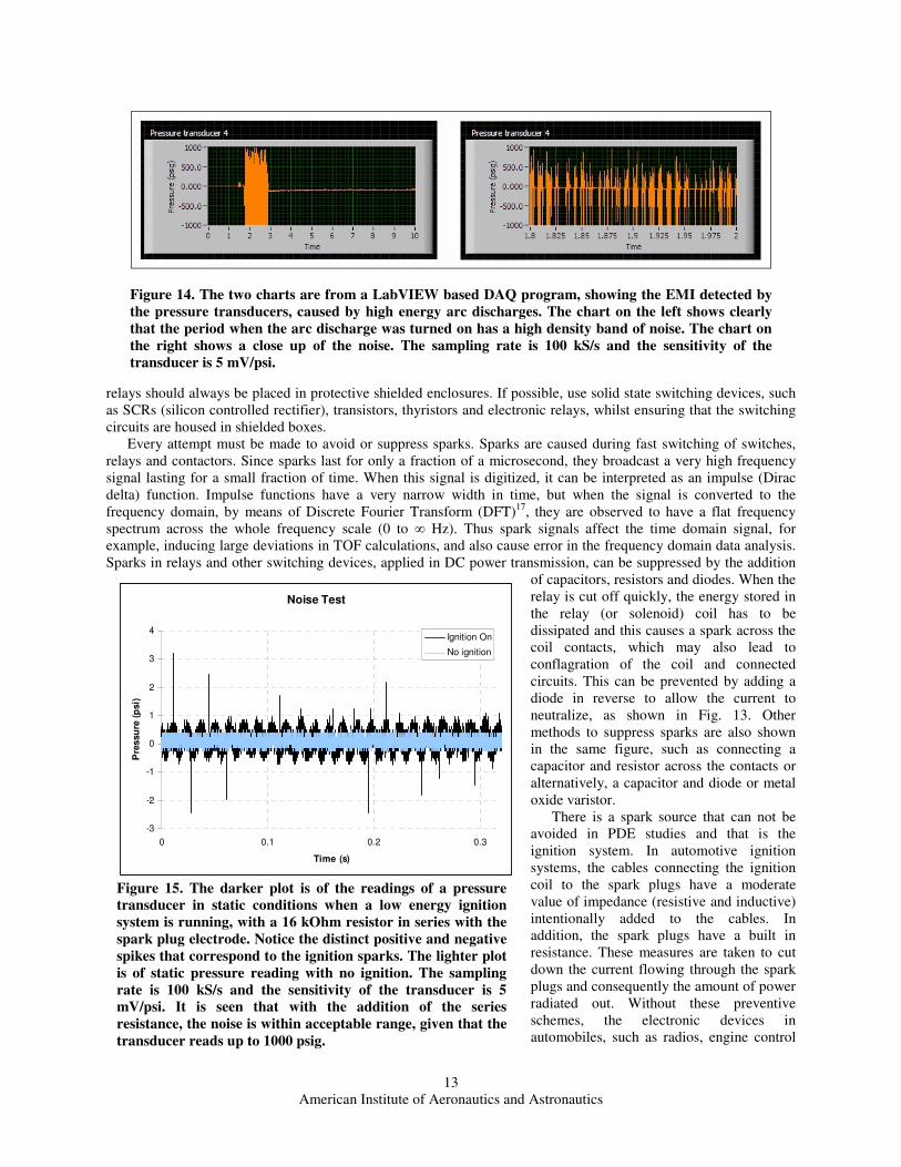
Figure 14. The two charts are from a LabVIEW based DAQ program, showing the EMI detected by
the pressure transducers, caused by high energy arc discharges. The chart on the left shows clearly
that the period when the arc discharge was turned on has a high density band of noise. The chart on
the right shows a close up of the noise. The sampling rate is 100 kS/s and the sensitivity of the
transducer is 5 mV/psi.
Noise Test
-3
-2
-1
0
1
2
3
4
0 0.1 0.2 0.3
Time (s)
Pre
ssu
re (
psi)
Ignition On
No ignition
Figure 15. The darker plot is of the readings of a pressure
transducer in static conditions when a low energy ignition
system is running, with a 16 kOhm resistor in series with the
spark plug electrode. Notice the distinct positive and negative
spikes that correspond to the ignition sparks. The lighter plot
is of static pressure reading with no ignition. The sampling
rate is 100 kS/s and the sensitivity of the transducer is 5
mV/psi. It is seen that with the addition of the series
resistance, the noise is within acceptable range, given that the
transducer reads up to 1000 psig.

American Institute of Aeronautics and Astronautics
14
units, etc., would be inundated with electromagnetic noise originating from the ignition system. In PDEs, the tube being open on one end to the atmosphere, the spark signal has a conduit to travel outward rather than being absorbed and attenuated by the grounded metal body. Therefore, the most effective way to alleviate the effect of EMI from ignition sparks is to cut down their energy to just the value required for ignition to occur. For the PDE studies at the ARC, an inductive ignition system, capable of 150 mJ per spark, was used. By trial and error, a resistance value of
12 to 16 kΩ was found to cut down the spark induced EMI to within acceptable levels. Inductive ignition was found to be better for this study over capacitive discharge ignition systems, which have higher energy per spark and deliver a battery of sparks in rapid succession. As a result, they are stronger sources of EMI noise. However, they may be a candidate for flight weight PDEs or ground based PDEs for electric power generation, where diagnostics are not performed. Heavy ignition EMI is one of the reasons why arc discharge ignition is not preferred. Thus, it is better to ignite the mixture with a low energy spark and then progress to DDT. Care must be taken when designing the ignition system in PDEs to prevent the spark from discharging through sensitive instruments or transducers.
Common Mode (CM) vs. Differential Mode (DM): Noise is conducted in cables as either common mode or differential mode. A signal cable has two conductors, one to carry the signal from the source and one to return the current back to the source. In differential mode noise, the currents on both conductors due to noise are equal in magnitude and opposite in direction. In common mode, the currents are in the same direction. DM noise is easier to remove as most DAQs have terminals with DM configuration, in which the difference of the two conductors are measured at the terminals. CM noise can be minimized by using ferrite core beads on both conductors.
A few steps to minimize radiation coupled EMI are listed below. A square wave of angular frequency ω can be
approximated as being composed of the sum of a sinusoid of the frequency ω and the odd harmonics (3ω, 5ω, 7ω, etc.). Thus, square wave generators, such as digital clocks, digital switching systems, computers and the on-board clocks of DAQs, are sources of high frequency radiated noise. For that reason, it is imperative that all electronic systems used in the lab conform to the emission standards set down by regulatory agencies. The US organizations include the Federal Communications Commission (FCC), US military standards (e.g. MIL-STD-461) and the Society of Automotive Engineers (SAE) for vehicular systems, measurement methods, etc.
Coaxial cables with BNC termination and shielded twisted pair cables are preferred for analog signal transmission. However, keep the distance between the transducer and the DAQ (in some cases the signal conditioner or ADC) as short as possible to limit the absorption of radiated noise. Digital signals are more resistant by nature to noise. Therefore, it is safer to transmit digital signals over transmission lines, in case the DAQ is at a distance from the computer system. In cases where the DAQ is physically separated from the computer, it is advisable to use fiber optic cables, as they are immune to EMI and have virtually no losses over the length of the cable.
Avoid ground loops. Ground loops occur when the return line is grounded at both ends to ground references that may be at different potentials. Ideally, all the current going in the signal line should travel back to the source in the return line. Thus the two lines have equal and opposite currents. This is called a balanced line. Ground loops cause a current to flow in the return line that is not equal in magnitude to the current in the signal line as some of the current took a different path back. This is known as CM Current where there is a net current in the same direction as the signal and it interferes severely with the signal current.
Keep the signal conductor close to its return conductor and avoid separating the two wires. Such wide loops behave as antennae creating DM loops that can transmit or receive noise, leading to cross talk with other conductors. Thus it is good to use shielded twisted pairs or multi-cored cables holding several shielded twisted pair conductors within one sleeve to carry multiple analog signals over short to medium distances.
Box shielding is an effective method to attenuate radiation to circuits housed within. Consult a good resource on noise while configuring metallic shielding cases for sensitive devices, such as transducers, power supplies, amplifiers, DAQs, active filter circuits, ADCs and other circuits. Avoid large slits in the sheet metal. Use many circular holes, close to each other rather than a large slit or cut out. Connect the shielding to the common ground plane of the circuits housed within. Do not connect the shield to the grounds at both ends of the connecting cables, as the grounds may be at different potentials, again causing a ground loop. Route cables within enclosures along the metallic fixtures, frames, etc. and not across slits and holes.
Tie down coaxial cables carrying sensitive analog signals so that they do not flex or vibrate during test runs, to avoid electric noise due to triboelectric effect. Triboelectric effect is observed as static electricity when glass is rubbed with silk. Copper, nickel, vinyl, polyester, Teflon, etc. develop a net negative charge, while glass, mica, nylon, aluminum, paper, etc. contract a net positive charge when rubbed against other materials. Some of the above mentioned materials are commonly used in cables, insulation and mounting equipment.
If after all possible preventive measures have been taken and the signals are still affected by noise, then one must employ filters. Hardware filters, either passive filters in the form of ferrite cores, resistors, capacitors and inductor circuits, or active filters, that have semiconductor devices, can be applied at the measuring source. Software filtering

American Institute of Aeronautics and Astronautics
15
methods can be applied post acquisition. LabVIEW offers many software filtering schemes, running averaging and other methods to clean up acquired data. LabVIEW also offers digital filters that mimic hardware filters and can clean the noise out of signals during the data acquisition process, using post ADC techniques.
EMI suppression should be considered at the design stage of the project and not as a retroactive procedure alone, in order to be able to offer the greatest protection for all electronic systems. References12,13,14 on EMI should be consulted to find out more about how to prevent noise from wreaking havoc with the data collection process. The above mentioned references give proper directions for building circuit boards, shielded housings, laying out cabling, etc.
With numerous variables and sources of sparks, interference, etc., the chances of electrical system failure is likely during PDE tests (or any other high energy tests such as detonation tubes, shock tubes, etc.). Therefore, it is wise to provide back up power, such as an Uninterruptible Power Supply (UPS), to the computers and the DAQ involved in the control and diagnostics. This is because surges or spikes can travel back through the power lines and may cause circuit breakers to trip.
G. Data Processing and Storage
Diagnostics of PDE test runs conducted at very high sampling rates for extended periods of time will generate enormous files at very high data rates. This section will discuss some of the issues encountered during data acquisition and will offer some solutions to the problems discussed.
Data storage issues are key deterrent to using the high sampling rates required to accurately describe the PDE processes. For example, 8 channels at 1 MS/s each generate 8 million discrete points of data per second. Writing this data to file can cause the computer system to fail, if it is not able to keep up with the writing as more and more data flows in. If the data is stored as a text file (.txt) or data file (.dat) format, each point would be 8 or even 16 bytes long. Thus the file size would be very huge but more importantly, the computer will not be able to write the data to file in time and can result in an overflow condition and cause the program to shut down.
It is therefore advantageous to use binary data format for writing large volumes of data, as the word sizes are as small as 1, 2 or 4 bytes per data point, enabling fast writing and smaller file sizes. Another data format introduced by National Instruments which is used in their proprietary programming system, LabVIEW™, is the TDM file, which stands for Technical Data Management. TDM files are also fast and reliable and use small storage spaces. They store descriptive properties of the data in XML, allowing for data mining, a valuable tool when sorting through very large volumes of data. The bulk of the data in TDM files is still stored as binary.
The DAQ can be programmed to sample data in regular intervals at sampling rates greater than 1 MS/s, e.g., sample for one second every 5 seconds. Thus the disks have ample time in between sampling to store the data.
The bottle necks in most computers when it comes to writing data rapidly are the RAM and the hard drive. For 32 bit computers, 4GB of RAM is the maximum allowable limit. It is important to install this limit of RAM to give the computers the ability to handle large volume flows encountered in DAQs. RAM speeds are rated in the range of 533 to 800 MHz, capable of reading or writing data higher than 528 MB/s. Comparatively hard disks are very slow, able to transfer data only at the rate of between 5 to 40 MB/s, with newer SATA disks (described below) capable of as high as 150 MB/s.
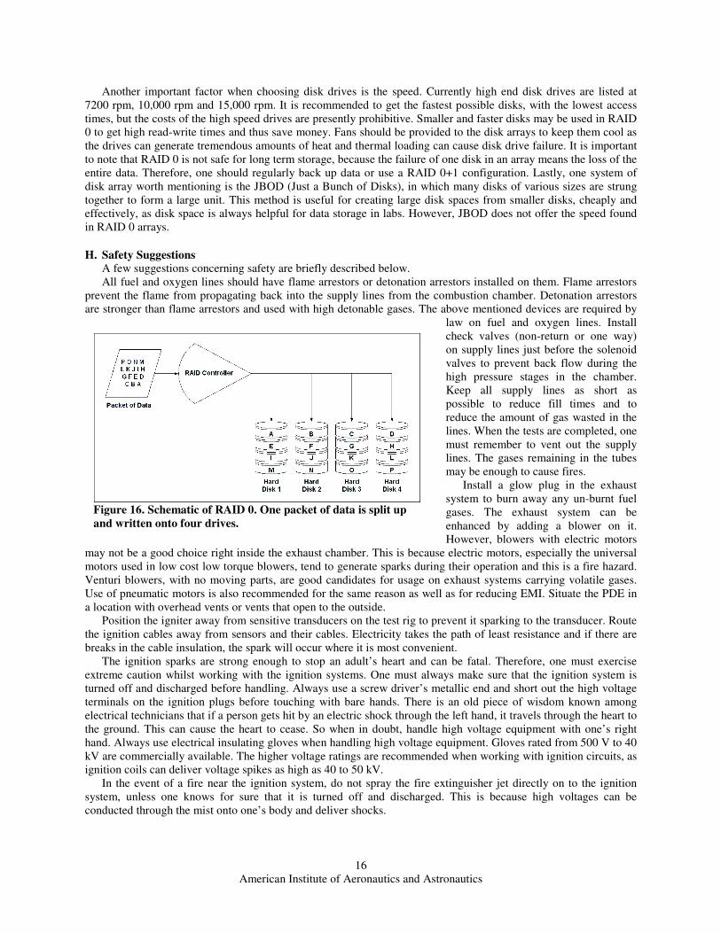
One way to speed up the hard disk’s ability to read and write data is to implement RAID16 in the DAQ computers. RAID stands for Redundant Array of Inexpensive/Independent Disks. It is a system in which many disk drives are joined together in an array and behave as one. In RAID 0, each packet of data is broken up into n pieces and each piece is stored in one of the n disks in the array in serial order. Thus RAID 0 is used for high speed writing and reading. Each disk must be of the exact same size and the total capacity is the sum of all disks together. RAID 1 creates a mirror copy of one disk onto one or more disks. Thus RAID 1 creates redundancy for the protection of data from perishing in the case of disk failure. RAID 0+1 is the combination of the two for speed and safety. RAID can be installed on desktop PCs as well as servers and may require the addition of a RAID controller card for interfacing 3 or more disks.
When selecting the RAID type, one must pay attention to the type of disk drives. Newer SATA (Serial Advanced Technology Attachment) disks transfer data serially but are capable of much higher speeds than the older PATA (Parallel ATA) disks. The newer version of SATA_ SATA II or SATA 3.0 Gb/s_ is relatively inexpensive and offer data transfer rates of 300 MB/s. SATA disks are good choices to create a RAID array. However, an older parallel standard called the SCSI (Small Computer System Interface) is faster than SATA allowing up to 320 MB/s per bus, with each bus capable of carrying up to 16 disks. SCSI interfaces are found on higher end machines and are more expensive. Currently RAID 0 implemented on SCSI disks is unbeatable in terms of speed. One way to overcome the high cost is to use smaller cheaper SCSI disks to write data and then transfer the data to slower and larger disks at a later stage.
American Institute of Aeronautics and Astronautics
16
Another important factor when choosing disk drives is the speed. Currently high end disk drives are listed at 7200 rpm, 10,000 rpm and 15,000 rpm. It is recommended to get the fastest possible disks, with the lowest access times, but the costs of the high speed drives are presently prohibitive. Smaller and faster disks may be used in RAID 0 to get high read-write times and thus save money. Fans should be provided to the disk arrays to keep them cool as the drives can generate tremendous amounts of heat and thermal loading can cause disk drive failure. It is important to note that RAID 0 is not safe for long term storage, because the failure of one disk in an array means the loss of the entire data. Therefore, one should regularly back up data or use a RAID 0+1 configuration. Lastly, one system of disk array worth mentioning is the JBOD (Just a Bunch of Disks), in which many disks of various sizes are strung together to form a large unit. This method is useful for creating large disk spaces from smaller disks, cheaply and effectively, as disk space is always helpful for data storage in labs. However, JBOD does not offer the speed found in RAID 0 arrays.
H. Safety Suggestions
A few suggestions concerning safety are briefly described below. All fuel and oxygen lines should have flame arrestors or detonation arrestors installed on them. Flame arrestors
prevent the flame from propagating back into the supply lines from the combustion chamber. Detonation arrestors are stronger than flame arrestors and used with high detonable gases. The above mentioned devices are required by
law on fuel and oxygen lines. Install check valves (non-return or one way) on supply lines just before the solenoid valves to prevent back flow during the high pressure stages in the chamber. Keep all supply lines as short as possible to reduce fill times and to reduce the amount of gas wasted in the lines. When the tests are completed, one must remember to vent out the supply lines. The gases remaining in the tubes may be enough to cause fires.
Install a glow plug in the exhaust system to burn away any un-burnt fuel gases. The exhaust system can be enhanced by adding a blower on it. However, blowers with electric motors
may not be a good choice right inside the exhaust chamber. This is because electric motors, especially the universal motors used in low cost low torque blowers, tend to generate sparks during their operation and this is a fire hazard. Venturi blowers, with no moving parts, are good candidates for usage on exhaust systems carrying volatile gases. Use of pneumatic motors is also recommended for the same reason as well as for reducing EMI. Situate the PDE in a location with overhead vents or vents that open to the outside.
Position the igniter away from sensitive transducers on the test rig to prevent it sparking to the transducer. Route the ignition cables away from sensors and their cables. Electricity takes the path of least resistance and if there are breaks in the cable insulation, the spark will occur where it is most convenient.
The ignition sparks are strong enough to stop an adult’s heart and can be fatal. Therefore, one must exercise extreme caution whilst working with the ignition systems. One must always make sure that the ignition system is turned off and discharged before handling. Always use a screw driver’s metallic end and short out the high voltage terminals on the ignition plugs before touching with bare hands. There is an old piece of wisdom known among electrical technicians that if a person gets hit by an electric shock through the left hand, it travels through the heart to the ground. This can cause the heart to cease. So when in doubt, handle high voltage equipment with one’s right hand. Always use electrical insulating gloves when handling high voltage equipment. Gloves rated from 500 V to 40 kV are commercially available. The higher voltage ratings are recommended when working with ignition circuits, as ignition coils can deliver voltage spikes as high as 40 to 50 kV.
In the event of a fire near the ignition system, do not spray the fire extinguisher jet directly on to the ignition system, unless one knows for sure that it is turned off and discharged. This is because high voltages can be conducted through the mist onto one’s body and deliver shocks.
Figure 16. Schematic of RAID 0. One packet of data is split up
and written onto four drives.

American Institute of Aeronautics and Astronautics
17
Conclusion
This paper discusses operational issues examined and resolved over several years of PDE studied at the ARC in UT Arlington. Most of the PDE studies up to date involve single shot experiments or very short run times of 10 to 20 seconds. However, longer run times are required to test and analyze technologies for applications in practical flight model PDEs or for ground based power generation usage. Some of the concerns that limit the run time of PDEs are examined and possible solutions are offered. One main obstacle is the heating of the tubes, components and diagnostic instruments. A few methods to increase heat transfer and improve cooling are pointed out, including water or liquid cooling of all components exposed to heat. Another problem encountered is the damage to Shchelkin spirals, which are the most successful devices in inducing in DDT rapidly. The solutions offered include crafting spirals out of thick walled hollow tubing with pressurized liquid coolant injection, cutting helical grooves on the internal walls of a water cooled tube and to manufacture helically cut sleeves that are modular and can be easily replaced after a set run time. Spark plugs suffer major damage during testing in PDEs and their soundness is critical during the duration of the test run. A hand made design is shown along with a method for adapting commercially available automotive spark plugs for PDE applications. The disadvantages of mechanical rotary valves used for gas injection into PDEs are compared with the advantages of using solenoid valves and electronic fuel injectors. These advantages include modularity, low costs, fast response times and ease of precision control using digital signals generated by the DAQ system computer. Some issues affecting data acquisition are also looked at, including the proper application of pressure transducers, choosing appropriate sampling rates and protection of the sensors from heat and noise. Noise is a major contributor to uncertainty in measurements. The instruments and devices commonly found in labs are significant sources of EMI and they can severely hamper the data acquisition process. One big source of EMI that cannot be avoided is the ignition system. Possible solutions for noise are offered. The authors recommend that noise prevention be done proactively at the experiment design stage, rather than retroactively. Fiber optic data transmission is a new solution available to engineers for signal transmission over longer distances without being affected by EMI. Some recommendations are also presented for handling the large amounts of data collected by the DAQ for instance applying RAID in computers. Finally, a few safety concerns are discussed for preventing possible catastrophes in the PDE testing labs.
References 1Kailasanath, K. “Recent developments in the research on pulse detonation engines,” AIAA Paper 2002-0470, AIAA 40th
Aerospace Sciences Meeting, 2002. 2New, T. H., Panicker, P. K., Lu, F. K., Tsai, T. M., “Experimental Investigations on DDT Enhancements by Schelkin Spirals
in a PDE”, 44th AIAA Aerospace Sciences Meeting and Exhibit, 9th-12th January 2006, Reno, Nevada 3Lu, F.K., Meyers, J.M., and Wilson, D.R. “Experimental study of a pulse detonation rocket with Shchelkin spiral,”
Proceedings 24th Int. Symp. Shock Waves, 2004 4Lu, F.K. and Wilson, D.R., "Recent research on detonation engines and drivers at the University of Texas at Arlington," 11th
ONR Propulsion Program Contractors Meeting, West Palm Beach, Florida, August 17–19, 1998 5Stuessy, W.S. and Wilson, D.R., "Experimental investigation of an annular pulse detonation wave engine," AIAA Paper 97–
0808, AIAA 35th Aerospace Sciences Meeting, Reno, Nevada, January 6–9, 1997 6Kim, H. Y., Lu, F.K., "An experimental and computational study of oxyhydrogen detonation wave propagation in a tube,"
Paper 2000–2389, 21st AIAA Advanced Measurement and Ground Testing Technology Conference, June 19–22, 2000, Denver, Colorado
7Meyers, J., Lu, F.K. and Wilson, D.R., "Performance enhancements on a pulsed detonation rocket engine," AIAA Paper 2003–1173, 41st AIAA Aerospace Sciences Meeting and Exhibit, Reno, Nevada, January 6–9, 2003
8Nichols, T., Wilson, D.R. and Lu, F.K., “Cold flow simulations for a pulse detonation rocket ejector,” Paper ISABE-2005-1301, 17th International Symposium on Airbreathing Engines, September 4–9 2005, Munich, Germany
9Roseberry, C., "Arc-heated Gas Flow Experiments for Hypersonic Propulsion Applications", Doctoral Dissertation, Department of Mechanical and Aerospace Engineering, The University of Texas at Arlington, Arlington, TX, December, 2005.
10Handbook of Aviation Fuel Properties, 3rd ed., Coordinating Research Council, Inc., Alpharetta, GA, 2004, Pg. 2-33 11Lide, D.R., CRC Handbook of Chemistry and Physics, 87th ed. 2006-2007, Coordinating Research Council (CRC) Press,
Alpharetta, GA, 2006, Section 16, URL: http://www.hbcpnetbase.com , [Accessed online on 10 Oct 2006]. 12Morrison, R., Noise and Other Interfering Signals, John Wiley and Sons, Inc., New York, 1992, Ch. 1-8. 13Mills, J.P., Electromagnetic Interference Reduction in Electronic Systems, PTR Prentice Hall, New Jersey, 1993, Ch. 1-12. 14Mardiguian, M., Controlling Radiated Emissions by Design, Van Nostrand Reinhold, New York, 1992, Ch. 1-13. 15Godsey, W.J., Arc Suppression for Relay Contacts in DC Service, IRE Transactions on Component Parts, IEEE, June 1957,
URL: http://ieeexplore.ieee.org/iel6/8222/25286/01135909.pdf [accessed 10 Oct. 2006] 16Mueller, S., “Upgrading and Repairing PCs”, 17th ed., Que Publishing, 2006, Chap. 6, 7 and 8; URL:
http://www.quepublishing.com

American Institute of Aeronautics and Astronautics
18
17Figliola, R.S. and Beasley, D.E., Theory and Design for Mechanical Measurements, 3rd ed., John Wiley and Sons, Inc., New York, 2000, Ch. 2, 6,7 and 9.
18Pressure Catalog: Piezoelectric Sensors for Dynamic Pressure Measurements, PCB Piezotronics, Inc., URL: http://www.pcb.com/products/literature.php , Pg., 13, 76, 80 [Accessed 10 Oct. 2006].
19Chemkin software package release 3.7, Reaction Design, San Diego, CA 92121, URL: http://www.reactiondesign.com 20CEA, Chemical Equilibrium with Applications software package, Ver. 2 with CEAgui ver. 1.0, NASA, URL:
http://www.grc.nasa.gov/WWW/CEAWeb/