operational experiences with the a1900 fragment separator
TRANSCRIPT

Operational Experiences with the A1900 Fragment Separator
Andreas Stolz
NSCL / Michigan State University
Fragment Separator Expert Meeting
Grand Rapids, August 2016
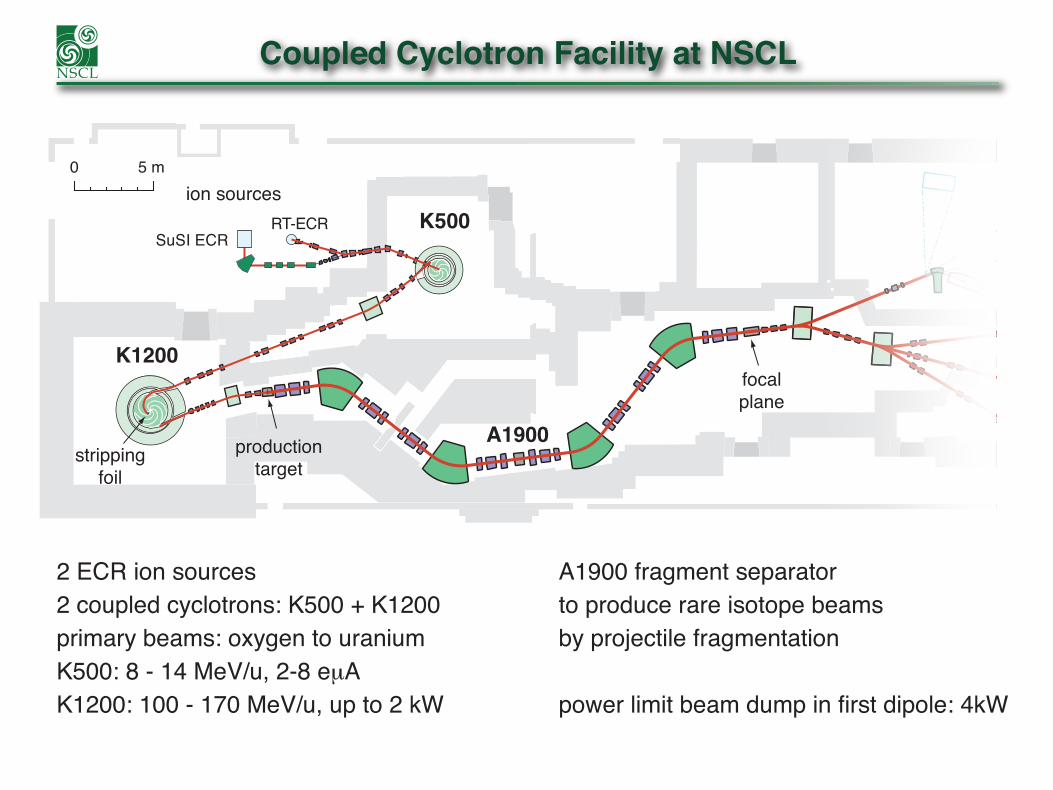
Coupled Cyclotron Facility at NSCL
0 5 m
SuSI ECRRT-ECR K500
A1900
K1200
strippingfoil
productiontarget
ion sources
focalplane
2 ECR ion sources2 coupled cyclotrons: K500 + K1200primary beams: oxygen to uraniumK500: 8 - 14 MeV/u, 2-8 eμAK1200: 100 - 170 MeV/u, up to 2 kW
A1900 fragment separatorto produce rare isotope beamsby projectile fragmentation
power limit beam dump in first dipole: 4kW

NSCL Primary Beam List
Primary beam list intensities are based on operational experience and serve as planning basis for experiments.
Usually, beam intensities above these valuses are provided to experiment.Beam power for Ca-48: 540 W
IsotopeEnergy[MeV/u]
Intensity[pnA] Isotope
Energy[MeV/u]
Intensity[pnA]
16O 150 175 82Se 140 3518O 120 150 78Kr 150 2520Ne 170 80 86Kr 100 1522Ne 120 80 86Kr 140 2522Ne 150 100 96Zr 120 1.524Mg 170 60 112Sn 120 436Ar 150 75 118Sn 120 1.540Ar 140 75 124Sn 120 1.540Ca 140 50 124Xe 140 1048Ca 90 15 136Xe 120 248Ca 140 80 208Pb 85 1.558Ni 160 20 209Bi 80 164Ni 140 7 238U 45 0.176Ge 130 25 238U 80 0.2

Primary Beam Statistics
Coupled Cyclotron Facility(CCF) delivers a differentprimary beam every 5 to7 days, typically 30 beamchanges per year.
The development ofnew primary beams(isotope and energy)is driven by userdemand.
CCF Primary Beam Isotope Statistics
average fractionof operating hoursOct 2010 - Oct 2015
Pb-208 [0.2%]Sn-118 [0.3%]Mg-24 [0.6%]Ne-20 [0.9%]Zr-96 [1.3%]Sn-112 [1.4%]Ne-22 [1.5%]U-238 [1.7%]Sn-124 [2.9%]
Xe-124 [3.0%]
Ca-40 [3.1%]
O-16 [3.9%]
Kr-86 [5.4%]
Ar-40 [5.4%]
Ni-58 [5.9%]O-18 [6.9%]
Ge-76 [7.4%]
Ar-36 [7.7%]
Se-82 [10.6%]
Kr-78 [12.4%]
Ca-48 [17.4%]

Rare Isotope Beams produced at NSCL
more than 1000 RIBs have been produced (2001-2016)more than 900 have been used in experiments
Neutron Number
Pro
ton
Num
ber 40
30
10
50
60
20
0 20 40 60 800
Observed isotopes
Produced at NSCLExperiments at NSCL
Primary Beams
100,102-104,106,108,110,112Sn134Te
60-66,72-78,80-86Ge64-70,76-91Se
104,105Sb
70-72,79-94Br76,78,84-99Rb 86-103Sr
87-106Y 80-81,91-108Zr83-84,93-111Nb 84-85,96-112Mo
99-115Tc 100-118Ru104-112,116-122Rh 106-115,118-125Pd
108-117,121-128Ag
69,70,72,74,81-96Kr
41-61Sc 39-40,43-63Ti44-66V
52-75Co 48,54-64,67-78Ni55,57-58,62,67,71,73,75-80Cu 60,62-63,72,74,76,78-81Zn
65-68,75-80,82-90As63,64,71-76,78-83Ga
45-46,50-72Fe48-70Mn
36-58Ca32-50Cl
35-56K 31-53Ar28,30-48S26-45P 22-24,26-44Si23-43Al 20,22-38,40Mg20-35,37Na 18-32,34Ne17-27,29,31F 13-24O12-23N 9-18,20C8,10-15,17,19B 7,10-12,14Be7-9,11Li 4,6,8He1-3H
96,110-119,125-130Cd98,113-122,126-127,131-133In
43-44,46-68Cr

CCF Operations Statistics
NSCL operations hours:typically: 4500 hours/yearup to 6000 hours/year possible
During scheduled facility operationsNSCL operates on a 24/7 schedule.
Facility availability of more than 90% allows for reliable schedule and high user satisfaction
NSCL operations is certified according to ISO 9001, ISO14001, and ISO 180010
500
1000
1500
2000
2500
2001
Q3
2002
Q1
2002
Q3
2003
Q1
2003
Q3
2004
Q1
2004
Q3
2005
Q1
2005
Q3
2006
Q1
2006
Q3
2007
Q1
2007
Q3
2008
Q1
2008
Q3
2009
Q1
2009
Q3
2010
Q1
2010
Q3
2011
Q1
2011
Q3
2012
Q1
2012
Q3
2013
Q1
2013
Q3
2014
Q1
2014
Q3
2015
Q1
2015
Q3
CCF Operations Hours
Unscheduled off Scheduled off Secondary tuning Primary tuning Beam ready

A1900 Fragment Separator
image-2
image-1 image-3
focalplane
detectorbox
detectorbox
productiontarget
primarybeam
• superconducting magnets (NSCL design)• four 45° dipoles• 24 quadrupole magnets (5 different designs)• 16 quadrupoles with hexapole and octupole coils• high degree of symmetry to minimize aberrations
Parameter A1900moment. accept. Δp/p 5%angle accept. [mrad] 60 x 40Bρmax [Tm] 6resolving power ~2900

A1900 Fragment Separator Standard Ion Optics
image-2
image-1 image-3
focalplane
detectorbox
detectorbox
productiontarget
primarybeam
D1 D2 D3 D4
D1
D2 D3
D4
xz
1st order calculation
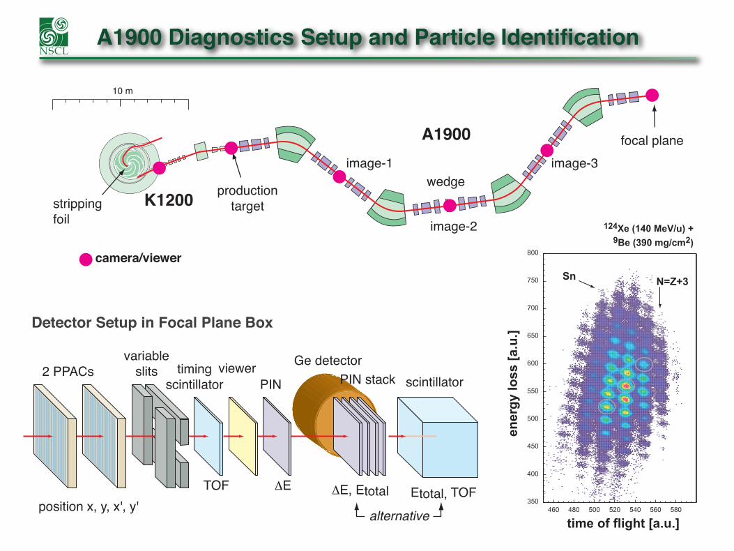
A1900 Diagnostics Setup and Particle Identification
K1200
A1900
productiontarget
image-2
image-1 image-3wedge
focal plane
10 m
strippingfoil
camera/viewer
Detector Setup in Focal Plane Box
350
400
450
500
550
600
650
700
750
800
460 480 500 520 540 560 580
time of flight [a.u.]en
ergy
loss
[a.u
.]
Sn N=Z+3
124Xe (140 MeV/u) + 9Be (390 mg/cm2)
2 PPACsvariable
slits
position x, y, x', y'Etotal, TOFΔE, Etotal
PIN stackGe detector
scintillator
TOF
timingscintillator
ΔE
PINviewer
alternative

A1900 timing scintillator
Thin timing scintillators (BC-400) that are used throughout beam delivery have a limited life time. Material degradation affects timing resolu-tion and detection efficiency.
Life time depends on particle and beam intensi-ty. For higher Z and high intensities useful life can be less than 24 h.
A 2-position pneumatic drive was replaced with linear stepper motor drive:
Up to 10 pre-programmed positions can be used, enabling the switch to a fresh detector position with virtually no down time.
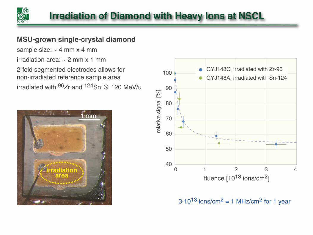
Irradiation of Diamond with Heavy Ions at NSCL
MSU-grown single-crystal diamondsample size: ~ 4 mm x 4 mm
irradiation area: ~ 2 mm x 1 mm
2-fold segmented electrodes allows fornon-irradiated reference sample area
irradiated with 96Zr and 124Sn @ 120 MeV/u
1 mm
irradiationarea
400 1
fluence [1013 ions/cm2]
3.1013 ions/cm2 = 1 MHz/cm2 for 1 year
2 3 4
50
60
70
rela
tive
sign
al [%
]
80
90
100GYJ148C, irradiated with Zr-96
GYJ148A, irradiated with Sn-124
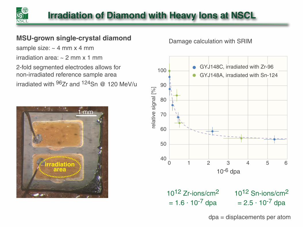
Irradiation of Diamond with Heavy Ions at NSCL
MSU-grown single-crystal diamondsample size: ~ 4 mm x 4 mm
irradiation area: ~ 2 mm x 1 mm
2-fold segmented electrodes allows fornon-irradiated reference sample area
irradiated with 96Zr and 124Sn @ 120 MeV/u
1 mm
irradiationarea
0 1
10-6 dpa2 3 4 5 6
40
50
60
70
rela
tive
sign
al [%
]
80
90
100GYJ148C, irradiated with Zr-96
GYJ148A, irradiated with Sn-124
Damage calculation with SRIM
1012 Zr-ions/cm2
= 1.6 . 10-7 dpa1012 Sn-ions/cm2
= 2.5 . 10-7 dpa
dpa = displacements per atom
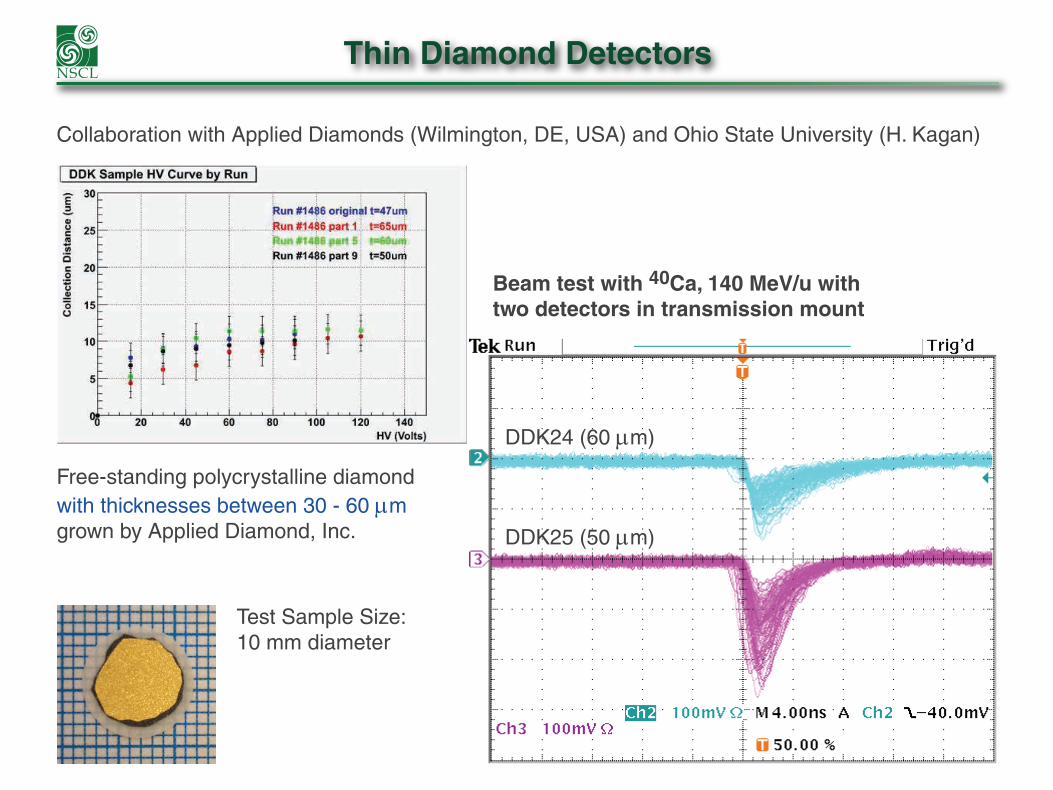
Thin Diamond Detectors
Collaboration with Applied Diamonds (Wilmington, DE, USA) and Ohio State University (H. Kagan)
Free-standing polycrystalline diamondwith thicknesses between 30 - 60 µmgrown by Applied Diamond, Inc.
Beam test with 40Ca, 140 MeV/u with two detectors in transmission mount
DDK24 (60 µm)
DDK25 (50 µm)
Test Sample Size:10 mm diameter

Thin Diamond Tracking Detector Prototype
Collaboration with Applied Diamonds (Wilmington, DE, USA)
Active area: 200 mm x 20 mmThickness: 50 µmSegmentation: 40 strips

Fragmentation of U-238 at 80 MeV/u
Experiment ran June14-17, 2016Target scan done at two production settings: Bρ = 3.1853&3.1748 Tm before XFP scintillator Bρ = 3.0830 Tm after XFP scintillator
TOF measured with RF frequency and between two ~140 um H2C10 scintillators
Energy loss measured using Si stack detectorsrange of products near U ~ 1000 µm
Stack 1: Ortec Si Surface barrier with cooling down to –4°C305, 306, 997, 998, 2000 µm
Stack 2: Micron Si PIN at room temperature508, 509, 1036, 1000, 1000 µm
Primary Goal: Produce and identify fragmentation products around Z~92

Fragmentation of U-238 at 80 MeV/uNew A1900 DAQ module test:Mesytec MADC-32 & MTDC-32 modules allow up to 13 bit channel resolution
Micron Si PIN, Resolution of energy peak from primary beam FWHM~4.5-6.0% with no coolingFragments change charge state in 147 µm scintillatordp/p=0.14% -- no tracking detectorsparticle rate<1 kHz

Fragmentation of U-238 at 80 MeV/uNew A1900 DAQ module test:The multihit Mesytec MTDC-32 has with adjustable time resolution from 3.9-500 ps.The TKE vs TOF spectrum using data from the MTDC adjusted to a 62.5 ps resolution is as good as the one from a TAC with a range of 1000 ns.Mesytec CFD-16 designed to provide fast timing with MTDC with remotely adjustable parameters. This module can provide an ECL & analog output directly to a TDC/QDC/ADC
TAC MTDC

NSCL’s Experimental Facility Plan
Gas Stopping Thermalized Beams Reaccelerated Beams
SweeperMagnet
MoNALISA
RFFS
ECR IonSources
K500Cyclotron
A1900FragmentSeparator
K1200Cyclotron BCS
DDASSuN
NERO
NeutronWalls
S800
Space for future expansionof the science program
SeGaHiRA
CAESARLENDA
GRETINA
EBIT ChargeBreeder
ANL GasCatcher
MomentumCompression Beam Lines
LaserSpectroscopy
LEBITSIPT
AT-TPC
RFQ
ANASEN
SECAR JENSA
ReA3
SEETF
0 10m
NSCL is the only facility in the world that can provide fast, thermalized,and reaccelerated beams of rare isotope.

Scheduled Operation with Two Accelerators in FY16
In FY16 (10/01/2015-07/23/2016) the NSCL carried out a user program with scheduledoperations of CCF and ReA3 for the first time.
Total Operating Hours: 4727 hours
3900 hrs beam delivery to 23 PAC approved experiments:15 CCF RIB experiments (11 with GRETINA) 3 stable beam experiments 5 CCF-ReA3 coupled RIB experiments

Gas Thermalization
Advanced Cryogenic Gas Stopper is being fabricated for installation on a second line next to ANL gas catcher.
ANL gascatcher
☞ Thursday 9:00 (Sumithrarachchi)

Helium Jet Ion Guide System
Helium-Jet Ion Source was constructed/tested at ORNL, now being installed on roof of N1 vault. Catcher cell will be at the focal plane of the A1900 fragment separator.
Thermalized ion will be transported using a wax aerosol in Helium gas through a thin capillary.
This system will allow for the harvesting of rare isotopes that would otherwise be lost on focal plane slits.
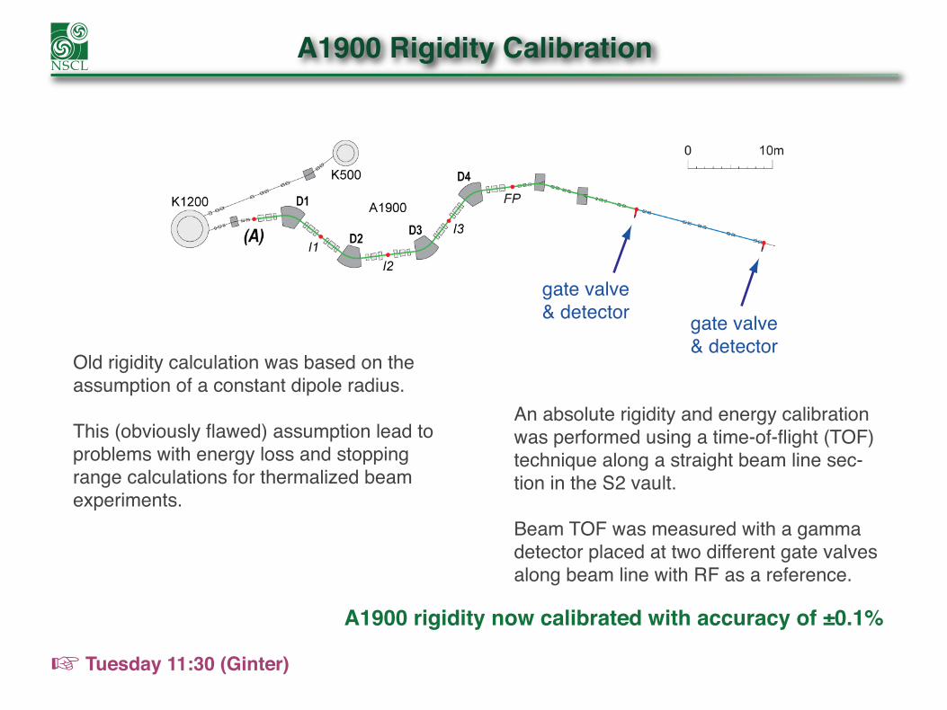
A1900 Rigidity Calibration
Old rigidity calculation was based on the assumption of a constant dipole radius.
This (obviously flawed) assumption lead to problems with energy loss and stopping range calculations for thermalized beam experiments.
An absolute rigidity and energy calibration was performed using a time-of-flight (TOF) technique along a straight beam line sec-tion in the S2 vault.
Beam TOF was measured with a gamma detector placed at two different gate valves along beam line with RF as a reference.
☞ Tuesday 11:30 (Ginter)
gate valve& detector gate valve
& detector
A1900 rigidity now calibrated with accuracy of ±0.1%

A1900 Rigidity Calibration
Based on the new rigidity calibration dipole radii in the A1900 were mapped as a func-tion of rigidity.
Different degraded primary beams were used over a range between 1.5 and 4.5 Tm.
☞ Tuesday 11:30 (Ginter)
Dipole 1
1% in ρ→ 1% in B ρ→ 2% in E

FRIB Construction and Alignment of the A1900
Due to concerns with floor movements during FRIB construction, an online floor level monitoring system (Geokon model 4675 Liquid Level Sensor) was installed under dipole 2, 3, and 4 of the A1900 fragment separator. Reference level was a sensor at the focal plane, assumed not to move.

FRIB Construction and Alignment of the A1900
-5.5
-5.0
-4.5
-4.0
-3.5
-3.0
-2.5
-2.0
-1.5
-1.0
-0.5
0.0
0.5
-5.5
-5.0
-4.5
-4.0
-3.5
-3.0
-2.5
-2.0
-1.5
-1.0
-0.5
0.0
0.520
14-0
2-01
2014
-03-
29
2014
-05-
24
2014
-07-
19
2014
-09-
13
2014
-11-
08
2015
-01-
03
2015
-02-
28
2015
-04-
25
2015
-06-
20
2015
-08-
15
2015
-10-
10
2015
-12-
05
2016
-01-
30
2016
-03-
26
2016
-05-
21
2016
-07-
16
2016
-09-
10
Mov
emen
t [m
m]
D4 D3 D2

Automated A1900 Dipole Matching
Dipoles have a long field settling timeAchieving correct final field required several adjustmentsManual matching requires operator attention➥ Development of predictive matching using B(t) analysis
0.000001
0.00001
0.0001
0.001
0.01
100 200 300
Delta-B vs Time (s)
400 500 600☞ Wednesday 12:00 (Steiner)

Automated A1900 Dipole Matching
“Typical” manual matchingby tired operator hitting matchbutton to adjust field many times
23:16 23:26
magnet set current
magnet field

Automated A1900 Dipole Matching
Matching algorithm usesNMR field measurementsduring first 2 minutes to predict final settling field
Magnet current adjustedbased on predicted settling field
Field settles to correct final value

CCF Operations Availability
0.4
0.5
0.6
0.7
0.8
0.9
1.0
Avai
labi
lity
Year2000 2002 2004 2006 2008 2010 2012 2014 2016
Cryo-plantturbine failure
Availability = MTBF / (MTBF + MDT)MTBF = Mean Time Between FailuresMDT = Mean Down Time

CCF Operations Availability
0
10
20
30
40
50
60
70
80
90
10020
11-1
0-01
2012
-01-
01
2012
-04-
01
2012
-07-
01
2012
-10-
01
2013
-01-
01
2013
-04-
01
2013
-07-
01
2013
-10-
01
2014
-01-
01
2014
-04-
01
2014
-07-
01
2014
-10-
01
2015
-01-
01
2015
-04-
01
2015
-07-
01
2015
-10-
01
Recovery Time (hrs)
CCF Availability (%)

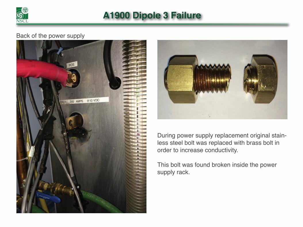
A1900 Dipole 3 Failure
12:00 15:00 18:00 21:00
A1900 Dipole 3 Failure
During power supply replacement original stain-less steel bolt was replaced with brass bolt in order to increase conductivity.
This bolt was found broken inside the power supply rack.
Back of the power supply

A1900 Dipole 3 Failure
Broken/melted diagnostic wires
After removing the lead can it became obvi-ous that superconducting lead wires were significantly damaged.

A1900 Dipole 3 Failure
Damaged coil package was replaced with spare one (4 weeks repair).
New work instructions for electrical lead connection: • silicon-bronze bolts (manufactured according to ASTM B99) from approved vendor • specified torque during installation • verify conductivity with milli-Ohm meter
Checked all magnet lead connections in the laboratory with milli-Ohm meter and thermal imaging under load.
Spare coil package just completed

A1900 Dipole 3 Failure
Time Line11/03/2015 Magnet failure
11/04/2015 Extent of damage realized, decision to warm up magnet Decision to turn off all superconducting magnets to inspect bolt connections
11/05/2015 Project plan with two options: Magnet Repair / Magnet Replacement
11/06/2015 Decision to start winter maintenance shutdown 5 weeks early
11/09/2015 Decision to replace magnet
11/25/2015 Old magnet removed, new coil package and iron yoke installed
12/10/2015 Cryo-welding completed
12/29/2015 Magnet filled with liquid Helium
01/05/2016 Magnet tested at 160 Amps
01/18/2016 Magnet tested with beam, rho calibration
➥ A $3 item used in the wrong way can cost you easily $3,000,000