operation, service, and repair manual for...
TRANSCRIPT
OPERATION, SERVICE, AND
REPAIR MANUAL
FOR TSURUMI TPG-SERIESPORTABLE GENERATORS
MODELSTPG-2900H-DXTPG-4300H-DXTPG-6000H-DX
TPG-7000H-DXE

LIMITED WARRANTYTSURUMI MANUFACTURING CO., LTD. (“TSURUMI”) warrants to the original end purchaser duringthe warranty period, every new TSURUMI generator or product to be free from defects in material andworkmanship under normal use and service, when properly installed, used, and maintained (in accor-dance with Tsurumi’s Operation, Service, and Repair Manual) for a period of two years from the datethe unit was first installed or twenty six months from the date of shipment by TSURUMI to wholesaler,whichever comes first.
TSURUMI’S sole obligation under this warranty is to repair or replace at TSURUMI’S option, with newor remanufactured parts, any part(s) that fail or that are found to be defective during the warranty peri-od. No allowance will be made for shipping charges, damages, labor, or other charges due to failure,repair or replacement.
This warranty does not apply to any TSURUMI product that has been disassembled without priorapproval of TSURUMI nor does it apply to any product that has been subjected to misuse, neglect,alteration, misapplication, accident or act of God.
TSURUMI assumes no responsibility for compliance with any regulations, codes, standards, or ordi-nances applicable to the installation, location, operation or maintenance of its products.
No other warranty, expressed or implied, is authorized by, or applicable to, the seller. No person, agentor dealer is authorized to enlarge upon this warranty.
TSURUMI expressly disclaims liability for consequential or incidental damages or breach of expressedor implied warranty; and any implied warrant of fitness for a particular purpose and merchantabilityshall be limited to the duration of the expressed warranty.
Some states do not allow limitations on the duration of an implied warranty, so the above limitation orexclusion may not apply to you. Some states do not allow the exclusion or limitation of incidental orconsequential damages, so the above limitation of exclusion may not apply to you.
This warranty gives you specific legal rights and you may also have other rights, which vary from stateto state.
Tsurumi Manufacturing Co., Ltd.

TABLE OF CONTENTSSection/Title Page1. Introduction . . . . . . . . . . . . . . . . . . . . . . . . . . . . . . . . . . . . . . . . . . . . . . . . . . . . . . . . 1
A. Precautions and Placards . . . . . . . . . . . . . . . . . . . . . . . . . . . . . . . . . . . . . . . . 2B. Safety Precautions . . . . . . . . . . . . . . . . . . . . . . . . . . . . . . . . . . . . . . . . . . . . . 4C. Specifications/Key Features . . . . . . . . . . . . . . . . . . . . . . . . . . . . . . . . . . . . . . . 5
2. Description and Operation . . . . . . . . . . . . . . . . . . . . . . . . . . . . . . . . . . . . . . . . . . . . . 6A. Physical Description . . . . . . . . . . . . . . . . . . . . . . . . . . . . . . . . . . . . . . . . . . . . 6B. Functional Description . . . . . . . . . . . . . . . . . . . . . . . . . . . . . . . . . . . . . . . . . . . 9
3. Operating Instructions . . . . . . . . . . . . . . . . . . . . . . . . . . . . . . . . . . . . . . . . . . . . . . . . 12A. Operating Controls . . . . . . . . . . . . . . . . . . . . . . . . . . . . . . . . . . . . . . . . . . . . . 12B. DC Circuit Controls . . . . . . . . . . . . . . . . . . . . . . . . . . . . . . . . . . . . . . . . . . . . . 12C. Check the Engine Oil Level . . . . . . . . . . . . . . . . . . . . . . . . . . . . . . . . . . . . . . . 15D. Check Engine Fuel . . . . . . . . . . . . . . . . . . . . . . . . . . . . . . . . . . . . . . . . . . . . . 16E. Pre-Start Checks . . . . . . . . . . . . . . . . . . . . . . . . . . . . . . . . . . . . . . . . . . . . . . . 17F. Starting and Operating the Engine . . . . . . . . . . . . . . . . . . . . . . . . . . . . . . . . . . 17G. Using the Generator . . . . . . . . . . . . . . . . . . . . . . . . . . . . . . . . . . . . . . . . . . . . 18H. AC Application . . . . . . . . . . . . . . . . . . . . . . . . . . . . . . . . . . . . . . . . . . . . . . . . . 18I. Stopping the Generator . . . . . . . . . . . . . . . . . . . . . . . . . . . . . . . . . . . . . . . . . . 20J. Oil Alert . . . . . . . . . . . . . . . . . . . . . . . . . . . . . . . . . . . . . . . . . . . . . . . . . . . . . . 21K. Idle Control . . . . . . . . . . . . . . . . . . . . . . . . . . . . . . . . . . . . . . . . . . . . . . . . . . . 21L. Stopping the Engine . . . . . . . . . . . . . . . . . . . . . . . . . . . . . . . . . . . . . . . . . . . . 21M. Wattage Information . . . . . . . . . . . . . . . . . . . . . . . . . . . . . . . . . . . . . . . . . . . . 21
4. Maintenance . . . . . . . . . . . . . . . . . . . . . . . . . . . . . . . . . . . . . . . . . . . . . . . . . . . . . . 23A. Changing Engine Oil . . . . . . . . . . . . . . . . . . . . . . . . . . . . . . . . . . . . . . . . . . . . 24B. Air Cleaner Service . . . . . . . . . . . . . . . . . . . . . . . . . . . . . . . . . . . . . . . . . . . . . 24C. Sediment Cup Cleaning . . . . . . . . . . . . . . . . . . . . . . . . . . . . . . . . . . . . . . . . . . 25D. Cleaning and Adjusting Spark Plug . . . . . . . . . . . . . . . . . . . . . . . . . . . . . . . . . 25
(Models TPG-4300H-DX, TPG-6000H-DX, TPG-7000H-DXE)5. Troubleshooting . . . . . . . . . . . . . . . . . . . . . . . . . . . . . . . . . . . . . . . . . . . . . . . . . . . . 27
A. Isolating Fault to the Generator or to the Control Panel . . . . . . . . . . . . . . . . . . 27B. Measuring Insulation Resistance . . . . . . . . . . . . . . . . . . . . . . . . . . . . . . . . . . . 27C. Electrical Limits Reference Chart . . . . . . . . . . . . . . . . . . . . . . . . . . . . . . . . . . . 28D. Troubleshooting Charts . . . . . . . . . . . . . . . . . . . . . . . . . . . . . . . . . . . . . . . . . . 29E. Wiring Diagrams . . . . . . . . . . . . . . . . . . . . . . . . . . . . . . . . . . . . . . . . . . . . . . . 35
6. Removal/Installation . . . . . . . . . . . . . . . . . . . . . . . . . . . . . . . . . . . . . . . . . . . . . . . . . 39A. Replacement of Battery . . . . . . . . . . . . . . . . . . . . . . . . . . . . . . . . . . . . . . . . . . 40B. Removal/Installation of Battery Enclosure . . . . . . . . . . . . . . . . . . . . . . . . . . . . 41C. Replacement of Engine Muffler . . . . . . . . . . . . . . . . . . . . . . . . . . . . . . . . . . . . 42
(Models TPG-4300H-DX, TPG-6000H-DX, TPG-7000H-DXE)D. Replacement of Engine Muffler . . . . . . . . . . . . . . . . . . . . . . . . . . . . . . . . . . . . 43
(Model TPG-2900H-DX)E. Replacement of Fuel Tank . . . . . . . . . . . . . . . . . . . . . . . . . . . . . . . . . . . . . . . . 45F. Removal/Installation of Engine and Generator as a Unit . . . . . . . . . . . . . . . . . . 47G. Replacement of Generator Stator . . . . . . . . . . . . . . . . . . . . . . . . . . . . . . . . . . 51H. Replacement of Rotor Bearing . . . . . . . . . . . . . . . . . . . . . . . . . . . . . . . . . . . . . 52I. Replacement of Rotor . . . . . . . . . . . . . . . . . . . . . . . . . . . . . . . . . . . . . . . . . . . 53J. Replacement of Front Panel Components . . . . . . . . . . . . . . . . . . . . . . . . . . . . 57
7. Storage Instructions . . . . . . . . . . . . . . . . . . . . . . . . . . . . . . . . . . . . . . . . . . . . . . . . . 628. Replacement Parts . . . . . . . . . . . . . . . . . . . . . . . . . . . . . . . . . . . . . . . . . . . . . . . . . . 63
A. Introduction . . . . . . . . . . . . . . . . . . . . . . . . . . . . . . . . . . . . . . . . . . . . . . . . . . . 63B. Ordering Parts . . . . . . . . . . . . . . . . . . . . . . . . . . . . . . . . . . . . . . . . . . . . . . . . . 63
Appendix A – Battery Enclosure Kit . . . . . . . . . . . . . . . . . . . . . . . . . . . . . . . . . . . . . . . . . . . A-1Appendix B – Wheel Kit Model PGWK-100 . . . . . . . . . . . . . . . . . . . . . . . . . . . . . . . . . . . . . B-1Appendix C – Wheel Kit Model PGWK-200 . . . . . . . . . . . . . . . . . . . . . . . . . . . . . . . . . . . . . C-1
1. INTRODUCTION
We thank you for purchasing a Tsurumi Generator. We are sure that the generator you have selectedwill meet all your portable electric power needs.
This manual applies to the Tsurumi Generators listed below. Specifications for the generators are pro-vided in the SPECIFICATIONS section. Key features of the generator are shown in the DESCRIPTIONsection.
TPG-2900H-DXTPG-4300H-DXTPG-6000H-DX
TPG-7000H-DXE
This manual provides instructions for operation, service, and repair of your generator. We strongly rec-ommend that those who operate the generator become familiar with the generator’s features and con-trols, and read the operating instructions before using the generator.
The Operation, Repair, and Service Manual also provides instructions to service, checkout, and repairthe generator. This manual also provides replacement parts information.
Repair and service information for the Honda engine is provided in the Owner’s Manual for ModelsGX160, GX240, GX340, and GX390. A copy of the Owner’s Manual has been provided in the gener-ator’s literature package. Parts information for the Honda Engine is available in Honda’s PartsCatalogs.
When there are differences between generator models, separate instructions are provided. The sep-arate instructions are provided to make sure the correct procedures are used on the affected genera-tors.
All information in the Tsurumi manuals is based upon the latest production configuration of the gener-ator at the time of approval for printing.
If you have a problem with your generator that cannot be resolved using the Operation, Repair, andService Manual, or if you have questions about the operation, service, repair, or maintenance of yourgenerator, contact your local Tsurumi generator dealer.
Page 1 Introduction
Tsurumi’s Operation, Service, and Repair Manual

A. PRECAUTIONS AND PLACARDS
Pay special attention to precautionary notes preceded by the words WARNING, CAUTION, andNOTE.
WARNINGS indicate that there is a strong possibility of personal injury or loss of life if the procedureis not followed, or if cleaning, lubricating, adhesives, and other materials are not used properly.
CAUTIONS indicate that there is a possibility of equipment damage if instructions are not followed.
NOTES are used in procedures to provide additional or supplemental information to make the proce-dure easier or more efficient.
WARNING:
THE GENERATOR IS DESIGNED TO GIVE SAFE AND DEPENDABLE SERVICE WHEN OPER-ATED ACCORDING TO THE INSTRUCTIONS IN THE TECHNICAL MANUAL PROVIDED WITHTHE GENERATOR.
DO NOT OPERATE THE GENERATOR BEFORE YOU HAVE READ AND UNDERSTAND THEINSTRUCTIONS AND THE ENGINE MANUFACTURERS MANUAL. FAILURE TO DO SOCOULD RESULT IN PERSONAL INJURY OR EQUIPMENT DAMAGE.
Introduction Page 2
Tsurumi’s Operation, Service, and Repair Manual
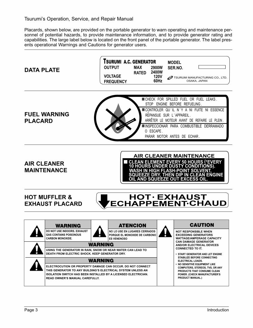
Placards, shown below, are provided on the portable generator to warn operating and maintenance per-sonnel of potential hazards, to provide maintenance information, and to provide generator rating andcapabilities. The large label below is located on the front panel of the portable generator. The label pres-ents operational Warnings and Cautions for generator users.
DATA PLATE
FUEL WARNINGPLACARD
AIR CLEANERMAINTENANCE
HOT MUFFLER &EXHAUST PLACARD
Page 3 Introduction
Tsurumi’s Operation, Service, and Repair Manual
OUTPUTTSURUMI A.C. GENERATOR
VOLTAGEFREQUENCY
MAXRATED
2900W2400W
120V60Hz
MODELSER.NO.
TSURUMI MANUFACTURING CO., LTD.OSAKA, JAPAN
CHECK FOR SPILLED FUEL OR FUEL LEAKS .STOP ENGINE BEFORE REFUELING .
CONTROLER QU ’ IL N ’ Y A NI FUITE NI ESSENCE
INSPECCIONAR PARA COMBUSTIBLE DERRAMADO
REPANSUE SUR L ’ APPAREIL .ARRETER LE MOTEUR AVANT DE REFAIRE LE PLEIN .
O ESCAPE .PARAR MOTOR ANTES DE ECHAR .
HOT EXHAUSTECHAPPEMENT CHAUD
DO NOT USE INDOORS. EXHAUSTGAS CONTAINS POISONOUSCARBON MONOXIDE.
WARNING
USING THE GENERATOR IN RAIN, SNOW OR NEAR WATER CAN LEAD TODEATH FROM ELECTRIC SHOCK. KEEP GENERATOR DRY.
WARNING
ATENCIONNO LO USE EN LUGARES CERRADOSPORQUE EL MONOXIDE DE CARBONOES VENENOSO
WARNINGELECTROCUTION OR PROPERTY DAMAGE CAN OCCUR. DO NOT CONNECTTHIS GENERATOR TO ANY BUILDINGS ELECTRICAL SYSTEM UNLESS ANISOLATION SWITCH HAS BEEN INSTALLED BY A LICENSED ELECTRICIAN.READ OWNERS MANUAL CAREFULLY.
NOT RESPONSIBLE WHENEXCEEDING GENERATORSWATTAGE/AMPERAGE CAPACITYCAN DAMAGE GENERATORAND/OR ELECTRICAL DEVICESCONNECTED TO IT.
START GENERATOR AND LET ENGINESTABILIZE BEFORE CONNECTINGELECTRICAL LOADS.
NO SENSITIVE EQUIPMENT LIKECOMPUTERS, STEREOS, TVS, OR ANYPRODUCTS THAT CONSUME CLEANPOWER. (CHECK MANUFACTURERSPRODUCT MANUAL.)
CAUTION

B. SAFETY PRECAUTIONS
WARNING:
• IN ORDER TO ASSURE SAFE AND EFFICIENT OPERATION OF THE GENERATOR, OPERA-TORS SHOULD READ AND COMPLY WITH THE FOLLOWING SAFETY PRECAUTIONS.
• Do not operate the generator near gasoline or gaseous fuels because of the potential dan-ger from explosion or fire. Do not fill the fuel tank with fuel while the engine is running. Do notsmoke or use open flame near the fuel tank. Be careful not to spill fuel during refueling. If fuel isspilled, wipe it off and let it dry before starting the engine.
• Do not place flammable materials near the generator. Be careful not to place fuel, matches,gunpowder, oily cloths, straw, trash, or any other combustibles near the generator.
• Do not operate the generator inside a room, cave, tunnel, or other insufficiently ventilatedarea. Always operate the generator in a well-ventilated area. The engine may become overheat-ed, and the poisonous carbon monoxide gas contained in the exhaust gases will endanger humanlives.
• Keep the generator at least 1 meter (3 feet) away from any structure or building during use.When a generator is located close to a building or nearby equipment, heat and exhaust from theengine will cause the surrounding temperature to rise. This will degrade the engines cooling effi-ciency, causing overheating.
• Do not enclose the generator nor cover it with a box. The generator has a built-in, forced-aircooling system, and may become overheated if it is enclosed.
• Operate the generator on a level surface. It is not necessary to prepare a special foundation forthe generator. However, the generator will vibrate on an irregular surface. Therefore, choose alevel place without surface irregularities.
• Shutoff the generator when moving the generator to another work site. It the generator is tilt-ed or moved during operation, fuel may spill and/or the generator may tip over, causing a haz-ardous situation. Proper lubrication cannot be expected if the generator is operated on a steepincline or slope. In such a case, the piston may seize; it may seize even if the oil is above the upperlevel.
• Do not operate in rain or with wet hands. The operator may suffer severe electric shock, if thegenerator is wet due to rain or snow. If wet, wipe dry well before starting. Do not pour water direct-ly over the generator, nor wash it with water.
• Do not connect the generator to a commercial power line. Connection to a commercial powerline may result in short circuit and damage the generator. When connecting to domestic circuits,install only approved transfer switches and make sure power and control circuitry meet local elec-trical code requirements.
• Do not smoke or use other smoking materials (pipes, cigars, etc.) while handling the bat-tery. The battery emits flammable hydrogen gas, which can explode if exposed to electric arcingor open flame. Keep the work area well ventilated and keep the battery away from openflames/sparks.
Introduction Page 4
Tsurumi’s Operation, Service, and Repair Manual

C. SPECIFICATIONS/KEY FEATURES
• Honda Powered…proven reliability…quiet operation…efficient fuel consumption
• Automatic Idle Control…reduces fuel consumption, noise, and engine wear (this feature is notavailable on Model TPG-2900H-DX).
• Large, Silent Muffler (with USDA qualified spark arrestor) to significantly reduce noise. Thespark arrestor is designed to screen out hot sparks.
• Large Air Filter…for superior emission control.
• Large Capacity Fuel Tank with Fuel Gauge…for extended run time.
• Rubber Vibration Pads…isolates generator/engine vibration from the frame for maximum pro-tection and noise reduction.
• Ground Fault Circuit Interrupter (GFCI)…on 120V duplex receptacle protects operator fromshock.
• Full Power Switch…allows voltage selection; either full-rated output from 120V receptacle or half-rated output from 120V receptacle and full-rated output from 240V receptacles (this feature is notavailable on Model TPG-2900H-DX).
• Circuit Breaker…protects generator from overload damage; can be reset with the flip of a switch(no fuse to replace).
• 100% Copper Windings…for long life.
Page 5 Introduction
Tsurumi’s Operation, Service, and Repair Manual
2. DESCRIPTION AND OPERATION
A. PHYSICAL DESCRIPTION
(1) Description of the Portable Generator
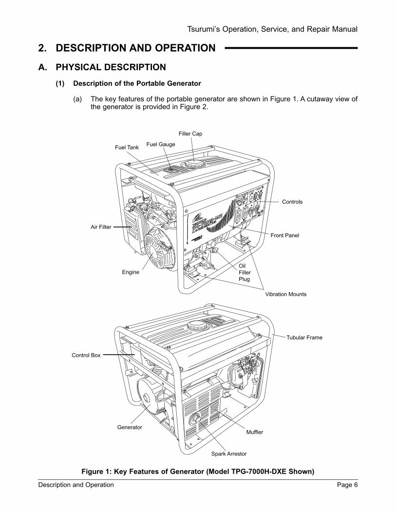
(a) The key features of the portable generator are shown in Figure 1. A cutaway view ofthe generator is provided in Figure 2.
Figure 1: Key Features of Generator (Model TPG-7000H-DXE Shown)
Description and Operation Page 6
Tsurumi’s Operation, Service, and Repair Manual
Filler Cap
Fuel GaugeFuel Tank
Air Filter
Engine
Controls
Front Panel
OilFillerPlug
Vibration Mounts
Control Box
Generator
Tubular Frame
Muffler
Spark Arrestor

(b) The generator consists of a tubular frame onto which is installed the generator,engine, front panel, control box and fuel tank.
(c) The generator and engine are installed on crossover plates that form the base of thetubular frame. Vibration isolators support the generator and engine unit. The isolatorsare fitted with threaded studs that secure the generator and engine unit to the frame.
(2) Description of Generator
(a) The generator consists of a rear cover, stator cover, stator, rotor, and front cover.
(b) The front cover of the generator attaches to the engine and forms the generator-to-engine interface.
(c) The front cover has a series of slots that allow entry of cooling air into the generator.A fan on the rotor circulates air through the generator.
(d) The rear cover has mounting lugs that are the generator-to-frame attachment points.The rear cover supports a ball bearing at the back end of the generator rotor.
(e) The rear cover has a removable access plate to provide access to the stator wiring(an access plate is not used on Model TPG-2900H-DX.)
(f) The rotor consists of a shaft, a stack of steel laminations, and copper wire windings.Components mounted on the rotor include a diode, a surge absorber, two permanentmagnets, and a cooling air fan.
(g) The windings and the laminated steel core form the field coil. The permanent mag-nets are used to induce voltage in the main coil of the stator. The diode and the surgeabsorber are located under the rotor windings at the bearing end of the rotor shaft.
(h) The rotor is attached to the engine crankshaft with a through bolt (tie-bolt). Theengine crankshaft is tapered and mates with a tapered bore in the rotor shaft. Theclamping force applied to the through bolt ties the rotor shaft to the engine crankshaft.
Figure 2: Cutaway of Generator (Model TPG-2900H-DX Shown)
Page 7 Description and Operation
Tsurumi’s Operation, Service, and Repair Manual
Tie-Bolts (3) Rotor
Vibration Mounts Ball Bearing Through-Bolt
Stator
Cooling Fan
Generator-To-Engine-Bolts
Tapered Shaft

(3) Description of the Engine
NOTE:
• Refer to the Honda engine Owner’s Manual for Models GX160, GX240, GX340, and GX390 for addi-tional coverage of the engine.
(a) The TPG-7000H-DXE generator has an electric starter and a recoil starter. All othergenerators are equipped with a recoil starter.
(b) The engine is equipped with an air filter to remove airborne contaminants from theengine inlet air.
(c) The engine is fitted with a muffler that provides quiet operation and controls the flowof engine exhaust gases. The muffler is attached to the rear generator cover using amounting bracket.
(d) The muffler for Models TPG-4300H-DX, TPG-6000H-DX, and TPG-7000-DX expelsexhaust gases through a port in the side of the muffler. The muffler for Model TPG-2900H-DX has a smaller muffler that expels gases through a curved tube on the bot-tom of the muffler.
(e) The muffler is fitted with a spark arrestor to screen-out sparks ejected in the exhaustgases. The spark arrestor for Models TPG-4300H-DX, TPG-6000H-DX, and TPG-7000-DX is installed in the exhaust port of the muffler. The spark arrestor for ModelTPG-2900H-DX is installed in the inlet side of the muffler.
(f) The engine has an oil filler plug that is used to check engine oil level. Engine oil isadded through the same filler plug port. The engine oil drain plug is installed in theengine casing adjacent to the oil filler plug.
(g) The engine has a carburetor choke control for starting the engine during cold weath-er operation. (Models TPG-4300H-DX, TPG-6000H-DX, and TPG-7000H-DXE havea ring-type choke control; Model TPG-2900H-DX has a choke lever.)
(4) Description of the Fuel Tank
(a) The fuel tank is attached to one side of the frame by two cushioned mounts. The tankis supported on the opposite side by cushioned pads that fit into a channel on thebackside of the front panel.
(b) A screen is provided under the filler cap to prevent entry of large contaminants.
(c) The tank has a fuel shutoff valve that is used to prevent fuel spillage when the gen-erator is not in use. The fuel shutoff valve is used to drain fuel from the tank if need-ed for replacement of generator components. The fuel shutoff valve should be closedduring transport to prevent fuel spillage.
(d) The fuel shutoff valve has a sediment bowl to capture heavier contaminants that mayhave passed through the fuel tank filler screen.
(5) Description of the Front Panel
NOTE:
• Refer to Figure 7 through Figure 10 for illustrations of the generator front panels. Familiarize your-self with the layout of the front panel for your generator before operating the generator.
(a) The operating controls, switches, lights, electrical receptacles, and circuit breakers forthe generator are mounted on the front panel.
(b) A control box is mounted on the back of the front panel. The control box contains theidle control unit, diode, condensers, and dc reset pushbutton switch (refer to Figure 11).
Description and Operation Page 8
Tsurumi’s Operation, Service, and Repair Manual

(c) The engine, starter, and control wiring exits through a hole in the side of the control box.The diode and fuse that are part of the DC circuit are located inside the control box.
(d) The generator leads and control wiring are connected inside the control box. A flexiblerubber sleeve provides protection for the generator wiring.
B. FUNCTIONAL DESCRIPTION
(1) Generation of No-Load Voltage (refer to Figure 3)
(a) When the generator rotor begins to rotate, the permanent magnet in the rotor gener-ates 3 to 6 volts alternating current in the main coil and in the condenser coil windings.
(b) The low voltage generated in the condenser coil also generates minute current flow (a)through the condenser coil. At the same time, low-level magnetic flux intensifies at therotor’s magnetic pole. As the magnetic force intensifies, voltage increases in the maincoil and in the condenser coil. As current (a) increases, magnetic flux also increases atthe rotor’s magnetic pole, and continues to increase as generator speed increases.
(c) As AC current flows through the condenser coil, the density of the magnetic flux in therotor changes. The change in magnetic flux density induces AC voltage in the field coil,and the diode rectifier in the field coil circuit rectifies the AC voltage into DC voltage.The resultant DC current flows (b) through the field coil and magnetizes the rotor coreto generate output voltage in the main coil.
(d) When the generator speed reaches 3000 to 3300 rpm (60 Hz generators), the currentin the condenser coil increases rapidly. This acts to stabilize the output voltage of eachcoil. When the generator speed reaches its rated speed, the generator output will beat its rated value.
(2) Voltage Fluctuations Under Load (refer to Figure 3)
(a) When output current (c) flows through the main coil to the appliance being used, amagnetic flux is produced and serves to increase current (a) in the condenser coil. Asa result, the current flowing in the field coil increases and the generator output voltageis prevented from decreasing.
Figure 3: Generation of No-Load Voltage
Page 9 Description and Operation
Tsurumi’s Operation, Service, and Repair Manual
Permanent magnetfor initial excitation
StatorMain coil
Appliance
Receptacle
Main coil
Condenser coil
Condenser
Field coilDiode
Surgeabsorber

(3) Full Power Switch (Dual Voltage Type) (refer to Figure 4)
(a) The full power switch provides both 120V and 240V dual voltages at full rated power.The full rated power will be available from one 120V receptacle and one 240V recep-tacle.
(b) Two main coils are wound over core of the stator. Each main coil outputs half therated power at the lower voltage (110V or 120V). These main coils are wound so theyare in the same phase. The full power switch reconnects these main coils in parallelor in series.
(c) Refer to the circuit diagram in Figure 4. When the full power switch is set for singlelower voltage indication (110V or 120V), the switch position will be as indicated by thelower coils line in the diagram.
Figure 4: Full Power Switch Circuit Diagram
(d) Refer to Figure 5 for a simplified diagram of the circuit. The two main coils are shownin parallel. In this case, the higher voltage (220V or 240V) at Receptacle (Rec.) 3 isnot available. Rec. 2 for the lower voltage is available up to the rated power (up to30A if the rated current is over 30A), and Rec. 1 is available up to 15A. When the fullpower switch is set for double voltage indication (110V/220V or 120V/240V), theswitch position is indicated by the upper dotted line in Figure 8.
(e) Refer to Figure 6 for a simplified diagram of the circuit. The two main coils are shownconnected in series. In this example, power is simultaneously available from thereceptacles for both voltages. Higher voltage receptacle, Rec. 3, has power availableup to rated power, however, Rec. 1 and Rec. 2 for the lower voltage can output onlyup to the rated power of each receptacle.
(f) Table 1 summarizes in tabular form the power available, or not available, dependingupon the position of the full power switch.
Description and Operation Page 10
Tsurumi’s Operation, Service, and Repair Manual
MC1
MC2
Rec. 1
120V(or 110V)
120V(or 110V)
120V/240V (or 110V/220V)
240V (or 220V)
Rec. 3
Rec. 2
120V (or 110V)

Figure 5: Full Power Switch Set for Single-Voltage Output
Figure 6: Full Power Switch Set for Dual-Voltage Output
Page 11 Description and Operation
Tsurumi’s Operation, Service, and Repair Manual
MC1
MC2
Rec. 2
120V(or 110V) 120V (or 110V)
MC1
MC2
Rec. 1
120V(110V)
Rec. 3
240V(220V)
Rec. 2
Table 1: Full Power Switch Switch Setting Versus Output Available
Switch Position
Lower Voltage Receptacle
Higher Voltage Receptacles
110V or 120V
Rated Output
No Output Can Be Taken
110V /120V or 120V / 240V
Half of Rated Output
Rated Output

3. OPERATING INSTRUCTIONS
A. OPERATING CONTROLS
(1) The main operating controls for the generator are, with a few exceptions, mounted on thefront panel of the generator.
(2) The controls consist of an ENGINE switch, an IDLE switch, a FULL POWER switch, aPILOT light, circuit BREAKER(s), a ground (or earth) post, and electrical receptacles. Thespecific controls used in each model are shown in Figures 7 through 10.
(3) The Model TPG-7000H-DXE generator is equipped with a electric starter motor. TheENGINE switch in this model is a key-operated, STOP/RUN/START switch. The spring-loaded switch is turned to the right to start the engine, and to the left to shut off the engine.
(4) The IDLE switch allows the generator speed to drop to idle speed if there is no electricalload demand on the generator. When an electrical load is sensed, the idle control increas-es the speed of the generator up to operating speed level. When there is no load, theengine speed returns to idle.
(5) The FULL POWER switch allows the generator to provide full rated power for the loadingappliances and/or tools. When the FULL POWER switch is set to on, power will be provid-ed to only one 120 Vac receptacle and one 240 Vac receptacle.
(6) The PILOT light provides an indication to the operator that the generator is generating elec-tricity.
(7) Circuit breakers are provided to protect the generator in the event of a short circuit. Thebreakers will trip when the circuit load exceeds the breaker’s rated value.
(8) The ground post is used to provide a positive ground for the generator. The post has awing-nut to quickly connect a ground wire to the generator.
(9) There are three types of receptacles: one 120 Vac, GFI-protected receptacles (two on mostmodels), one twist-type, 120 Vac receptacle, and one 120 Vac / 240 Vac, combinationreceptacle.
B. DC CIRCUIT CONTROLS
(1) The circuitry for DC circuit consists of a 10 Amp fuse, an overload protector, and a re-setswitch.
(2) In the event of an overload, the overload protector will trip the reset switch (refer to Figure 11).
Operating Instructions Page 12
Tsurumi’s Operation, Service, and Repair Manual
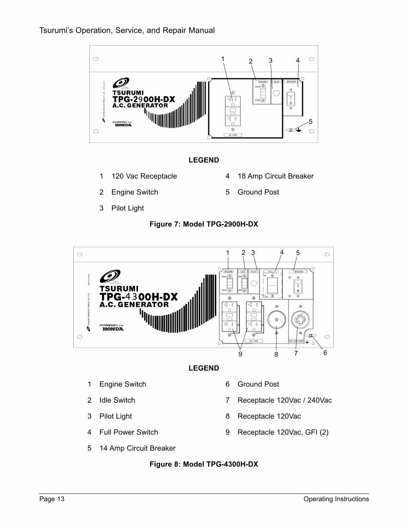
LEGEND
1 120 Vac Receptacle 4 18 Amp Circuit Breaker
2 Engine Switch 5 Ground Post
3 Pilot Light
Figure 7: Model TPG-2900H-DX
LEGEND
1 Engine Switch 6 Ground Post
2 Idle Switch 7 Receptacle 120Vac / 240Vac
3 Pilot Light 8 Receptacle 120Vac
4 Full Power Switch 9 Receptacle 120Vac, GFI (2)
5 14 Amp Circuit Breaker
Figure 8: Model TPG-4300H-DX
Page 13 Operating Instructions
Tsurumi’s Operation, Service, and Repair Manual
TSURUMIMANUFACTURING CO.,LTD.
TSU
RUM
I M
AN
UFA
CTU
RIN
G C
O.,
LTD
. M
AD
E IN
JA
PAN
RUN
STOP
OFF
ON
BREAKERENGINE PILOT
AC 120V
9
1 2 3 4
5
ON
OFF
BREAKERFULL
120
240120
IDLEENGINE PILOT
TSURUMIMANUFACTURING CO., LTD.
TSU
RUM
I M
AN
UFA
CTU
RIN
G C
O.,
LTD
. M
AD
E IN
JA
PAN
4
RUN
STOP
ON
OFF
3
MAX20MAX20
AC120V/240VAC 120V
1 2 3 4 5
6789
OF
O O
OF
BREAKERFULL
120
240120
IDLEENGINE PILOT
TSURUMIMANUFACTURING CO., LTD.
TSU
RUM
I M
AN
UFA
CTU
RIN
G C
O.,
LTD
. M
AD
E IN
JA
PAN
RU
STO
O
OF
6
MAX20 MAX20
AC120V/240VAC 120V
1 2 3 4 5 6
78910
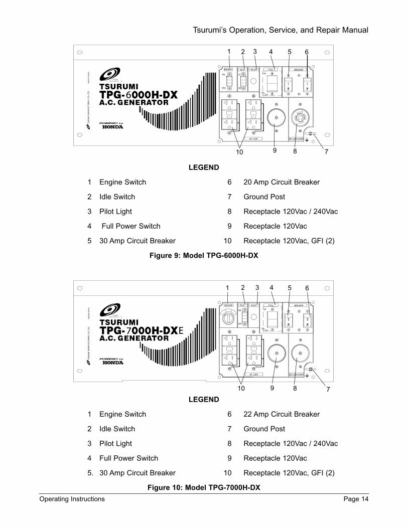
LEGEND
1 Engine Switch 6 20 Amp Circuit Breaker
2 Idle Switch 7 Ground Post
3 Pilot Light 8 Receptacle 120Vac / 240Vac
4 Full Power Switch 9 Receptacle 120Vac
5 30 Amp Circuit Breaker 10 Receptacle 120Vac, GFI (2)
Figure 9: Model TPG-6000H-DX
LEGEND
1 Engine Switch 6 22 Amp Circuit Breaker
2 Idle Switch 7 Ground Post
3 Pilot Light 8 Receptacle 120Vac / 240Vac
4 Full Power Switch 9 Receptacle 120Vac
5. 30 Amp Circuit Breaker 10 Receptacle 120Vac, GFI (2)
Figure 10: Model TPG-7000H-DX
Operating Instructions Page 14
Tsurumi’s Operation, Service, and Repair Manual
OFF
ON ON
OFF
BREAKERFULL
120
240120
IDLEENGINE PILOT
TSURUMIMANUFACTURING CO., LTD.
TSU
RUM
I M
AN
UFA
CTU
RIN
G C
O.,
LTD
. M
AD
E IN
JA
PAN
ON
OFF
7 E
MAX20 MAX20
AC120V/240VAC 120V
1 2 3 4 5 6
78910

Figure 11: DC Circuit Reset Pushbutton
C. CHECK THE ENGINE OIL LEVEL
CAUTION:
Engine oil is a major factor affecting performance and service life. Non-detergent oils and 2-stroke oils are not recommended because they have inadequate lubricating characteristics
Check the oil level with the engine on a level surface and the engine stopped.
(1) Use Honda 4-stroke oil, or use an equivalent high detergent, premium quality motor oil cer-tified to meet or exceed U.S. automobile manufacturer’s requirements for ServiceClassification SG, SF. Motor oils classified SG, SF will show this designation on the con-tainer.
(2) SAE 10W/30 is recommended for general, all-temperature use.
(3) Other viscosity grades shown in Figure 12 may be used when the average temperature inyour area is within the indicated range.
Figure 12: Oil Viscosity Grade-to-Temperature Recommendations
Page 15 Operating Instructions
Tsurumi’s Operation, Service, and Repair Manual
TO FRAME
Fuel Tank
Control Box
Reset Button
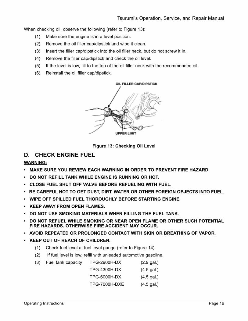
When checking oil, observe the following (refer to Figure 13):
(1) Make sure the engine is in a level position.
(2) Remove the oil filler cap/dipstick and wipe it clean.
(3) Insert the filler cap/dipstick into the oil filler neck, but do not screw it in.
(4) Remove the filler cap/dipstick and check the oil level.
(5) If the level is low, fill to the top of the oil filler neck with the recommended oil.
(6) Reinstall the oil filler cap/dipstick.
Figure 13: Checking Oil Level
D. CHECK ENGINE FUELWARNING:
MAKE SURE YOU REVIEW EACH WARNING IN ORDER TO PREVENT FIRE HAZARD.
DO NOT REFILL TANK WHILE ENGINE IS RUNNING OR HOT.
CLOSE FUEL SHUT OFF VALVE BEFORE REFUELING WITH FUEL.
BE CAREFUL NOT TO GET DUST, DIRT, WATER OR OTHER FOREIGN OBJECTS INTO FUEL.
WIPE OFF SPILLED FUEL THOROUGHLY BEFORE STARTING ENGINE.
KEEP AWAY FROM OPEN FLAMES.
DO NOT USE SMOKING MATERIALS WHEN FILLING THE FUEL TANK.
DO NOT REFUEL WHILE SMOKING OR NEAR OPEN FLAME OR OTHER SUCH POTENTIALFIRE HAZARDS. OTHERWISE FIRE ACCIDENT MAY OCCUR.
AVOID REPEATED OR PROLONGED CONTACT WITH SKIN OR BREATHING OF VAPOR.
KEEP OUT OF REACH OF CHILDREN.
(1) Check fuel level at fuel level gauge (refer to Figure 14).
(2) If fuel level is low, refill with unleaded automotive gasoline.
(3) Fuel tank capacity TPG-2900H-DX (2.9 gal.)
TPG-4300H-DX (4.5 gal.)
TPG-6000H-DX (4.5 gal.)
TPG-7000H-DXE (4.5 gal.)
Operating Instructions Page 16
Tsurumi’s Operation, Service, and Repair Manual
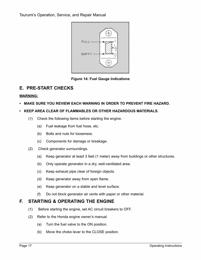
Figure 14: Fuel Gauge Indications
E. PRE-START CHECKS
WARNING:
MAKE SURE YOU REVIEW EACH WARNING IN ORDER TO PREVENT FIRE HAZARD.
KEEP AREA CLEAR OF FLAMMABLES OR OTHER HAZARDOUS MATERIALS.
(1) Check the following items before starting the engine.
(a) Fuel leakage from fuel hose, etc.
(b) Bolts and nuts for looseness.
(c) Components for damage or breakage.
(2) Check generator surroundings.
(a) Keep generator at least 3 feet (1 meter) away from buildings or other structures.
(b) Only operate generator in a dry, well-ventilated area.
(c) Keep exhaust pipe clear of foreign objects.
(d) Keep generator away from open flame.
(e) Keep generator on a stable and level surface.
(f) Do not block generator air vents with paper or other material.
F. STARTING & OPERATING THE ENGINE
(1) Before starting the engine, set AC circuit breakers to OFF.
(2) Refer to the Honda engine owner’s manual.
(a) Turn the fuel valve to the ON position.
(b) Move the choke lever to the CLOSE position.
Page 17 Operating Instructions
Tsurumi’s Operation, Service, and Repair Manual
NOTE:
• The choke may not be needed if the engine is warm or the air temperature is high.
(3) Move the throttle lever slightly to the left.
(4) (MODEL TPG-7000H-DXE ONLY): To start the engine using the electric starter, proceed asfollows:
(a) Turn key in engine START/STOP switch.
(b) Turn key fully right to START position. Hold in START position until engine starts.
(c) Release key; the key is spring-loaded to the RUN position.
(d) As the engine warms up, gradually move the choke lever to the OPEN position.
(e) Position the throttle lever at the desired engine speed.
(5) (ALL MODELS): When starting the engine using recoil starter, proceed as follows:
(a) Turn the engine switch to the ON position.
(b) Pull the starter grip lightly until resistance is felt, then pull briskly.
NOTE:
• When using the recoil starter, do not allow the starter grip to snap back against the engine. Returnit gently to prevent damage to the starter.
(c) As the engine warms up, gradually move the choke lever to the OPEN position.
(d) Position the throttle lever at the desired engine speed.
G. USING THE GENERATORWARNING:
TO PREVENT ELECTRICAL SHOCK FROM FAULTY APPLIANCES, THE GENERATORSHOULD BE GROUNDED. CONNECT A LENGTH OF HEAVY WIRE BETWEEN THE GENERA-TORS GROUND TERMINAL AND EXTERNAL GROUND SOURCE.
CONNECTIONS FOR STANDBY POWER TO A BUILDINGS ELECTRICAL SYSTEM MUST BEMADE BY A QUALIFIED ELECTRICIAN AND MUST COMPLY WITH ALL APPLICABLE LAWSAND ELECTRICAL CODES. IMPROPER CONNECTIONS CAN ALLOW ELECTRICAL CUR-RENT FROM THE GENERATOR TO BACK-FEED INTO THE UTILITY LINES. SUCH BACK-FEED MAY ELECTROCUTE UTILITY COMPANY WORKERS OR OTHERS WHO CONTACTTHE LINES DURING A POWER OUTAGE, AND WHEN UTILITY POWER IS RESTORED, THEGENERATOR MAY EXPLODE, BURN, OR CAUSE FIRES IN THE BUILDINGS ELECTRICALSYSTEM.
H. AC APPLICATION
A Single Voltage Type
(1) Check the pilot lamp for proper voltage.
NOTE:
• The generator is thoroughly tested and adjusted in the factory. If the generator does not producethe specific voltage, consult your nearest Tsurumi Generator dealer.
(2) Set switches on the electrical appliances to OFF before connecting to the generator.
(3) Insert the plug of the electrical appliance into the appropriate receptacle.
Operating Instructions Page 18
Tsurumi’s Operation, Service, and Repair Manual
NOTE:
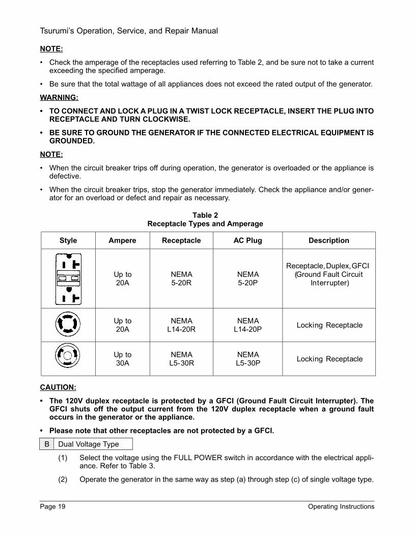
• Check the amperage of the receptacles used referring to Table 2, and be sure not to take a currentexceeding the specified amperage.
• Be sure that the total wattage of all appliances does not exceed the rated output of the generator.
WARNING:
TO CONNECT AND LOCK A PLUG IN A TWIST LOCK RECEPTACLE, INSERT THE PLUG INTORECEPTACLE AND TURN CLOCKWISE.
BE SURE TO GROUND THE GENERATOR IF THE CONNECTED ELECTRICAL EQUIPMENT ISGROUNDED.
NOTE:
• When the circuit breaker trips off during operation, the generator is overloaded or the appliance isdefective.
• When the circuit breaker trips, stop the generator immediately. Check the appliance and/or gener-ator for an overload or defect and repair as necessary.
CAUTION:
The 120V duplex receptacle is protected by a GFCI (Ground Fault Circuit Interrupter). TheGFCI shuts off the output current from the 120V duplex receptacle when a ground faultoccurs in the generator or the appliance.
Please note that other receptacles are not protected by a GFCI.
B Dual Voltage Type
(1) Select the voltage using the FULL POWER switch in accordance with the electrical appli-ance. Refer to Table 3.
(2) Operate the generator in the same way as step (a) through step (c) of single voltage type.
Page 19 Operating Instructions
Tsurumi’s Operation, Service, and Repair Manual

Table 3Available Receptacles With Full Power Switch On
Switch Setting Lower Voltage Receptacle Higher Voltage Receptacle
120V Rated Output is Available Unavailable
120V/240V Half of Rate Output is Available Rated Output is Available
WARNING:
TO TAKE OUT POWER FROM TWIST LOCK RECEPTACLE, INSERT THE PLUG INTO RECEP-TACLE AND TURN CLOCKWISE TO LOCK IT.
BE SURE TO GROUND THE GENERATOR IF THE CONNECTED ELECTRICAL EQUIPMENT ISGROUNDED.
NOTE:
• When the circuit breaker turns off during operation, the generator is overloaded or the appliance isdefective.
• Stop the generator immediately, check the appliance and/or generator for overloading or defect andrepair as necessary.
I. STOPPING THE GENERATOR
(1) Set the power switch to OFF or unplug the cord from the receptacle.
(2) Move the throttle lever fully to the right.
(3) Turn the engine switch to the OFF position.
(4) Turn the fuel valve to the OFF position.
Figure 15: Fuel Valve
Operating Instructions Page 20
Tsurumi’s Operation, Service, and Repair Manual

J. OIL ALERT(1) The oil alert detects the fall in oil level in the crankcase and automatically stops the engine
when the oil level falls down below the predetermined level.
(2) When the engine has stopped automatically, check the oil level. Refill engine oil to theupper level and restart the engine.
(3) If the engine does not start by usual starting procedures, check the oil level.
K. IDLE CONTROL (TPG-4300H-DX, TPG-6000H-DX, AND TPG-7000H-DXE) The idle control feature automatically reduces engine speed when there is no load on the generatorand automatically increases engine speed up to rated speed when load is applied.
The idle control feature provides fuel economy and low noise operation at no-load running.
(1) How To Use Idle Control
(a) Start the engine with IDLE switch set to OFF.
NOTE:
• Warm up the engine without a load for a few minutes.
(b) Set IDLE switch to the ON position.
(2) Checking Idle Function
(a) When the idle function does not operate normally, please check the following:
NOTE:
• Most induction loads, such as an electric motor, require wattage three to five times larger than theirrating at starting. This starting wattage should not exceed the rated output of the generator.
(b) Is the generator overloaded? Make sure that the generator is not overloaded.
(c) Turn the IDLE switch off when the idle control does not work normally under the ratedoutput.
L. STOPPING THE ENGINE(1) Turn off the switch of load or disconnect the load.
(2) Turn the IDLE switch off.
(3) Push ENGINE to stop.
NOTE:
• Allow the engine about 3 minutes to cool down at no-load before stopping.
M. WATTAGE INFORMATIONWhen starting some appliances, a “surge” of energy occurs. Depending upon the nature of the elec-trical load, the amount of electrical power needed to start the appliance may exceed the amount need-ed to maintain its use. See Table 4 for appliances you may use with this generator.
Electrical appliances and tools normally come with a label indicating voltage, cycles/Hz, amperage(amps) and electrical power needed to run the appliance or tool. Check with your nearest dealer withquestions regarding power surge of certain appliances or power tools.
Page 21 Operating Instructions
Tsurumi’s Operation, Service, and Repair Manual
Electrical loads such as incandescent lamps and hot plates require the same wattage to start as need-ed to maintain use.
Loads such as fluorescent and mercury lamps require 1.2 to 2 times the indicated wattage to start.Electric motors require a large starting current. Power requirements depend on the type of motor andits use. Once enough “surge” is attained to start the motor, the appliance will require only 50% to 30%of the wattage to continue running.
CAUTION:
Check motor starting current and power factor carefully.
Most electrical tools require 1.2 to 3 times their wattage for running. For example, the 5,000 watts gen-erated could power an 1800-watt to a 4000-watt electric drill.
Loads such as submersible pumps and air compressors require a very large force to start. They need3 to 5 times the wattage needed to maintain the tool in order to start. For example, a 5,000 watt gen-erator would only be able to drive a 1,000 watt to 1,700 watt pump.
NOTE:
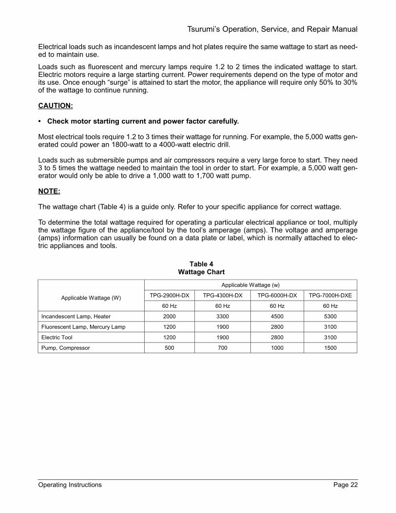
The wattage chart (Table 4) is a guide only. Refer to your specific appliance for correct wattage.
To determine the total wattage required for operating a particular electrical appliance or tool, multiplythe wattage figure of the appliance/tool by the tool’s amperage (amps). The voltage and amperage(amps) information can usually be found on a data plate or label, which is normally attached to elec-tric appliances and tools.
Operating Instructions Page 22
Tsurumi’s Operation, Service, and Repair Manual
Table 4 Wattage Chart
Applicable Wattage (w)
TPG-2900H-DX TPG-4300H-DX TPG-6000H-DX TPG-7000H-DXE
Applicable Wattage (W)
60 Hz 60 Hz 60 Hz 60 Hz
Incandescent Lamp, Heater 2000 3300 4500 5300
Fluorescent Lamp, Mercury Lamp 1200 1900 2800 3100
Electric Tool 1200 2800
Pump, Compressor 500 700 1000 1500
1900 3100
4. MAINTENANCE
To maintain the generator in peak operating condition, observe and implement the maintenance andadjustment schedule in Table 5. Inspect and/or service the generator as scheduled in Table 5.
WARNING:
• SHUT OFF THE ENGINE BEFORE PERFORMING ANY MAINTENANCE. IF OPERATION OFTHE ENGINE IS REQUIRED, MAKE SURE THE AREA IS WELL VENTILATED; THE ENGINEEXHAUST CONTAINS POISONOUS CARBON MONOXIDE GAS.
CAUTION:
Refer to the Honda engine owners manual for other maintenance requirements.
An initial oil change should be performed after the first twenty (20) hours of use. Thereafter, changeoil every 100 hours.
Before changing the oil, check for a suitable way to dispose of the used oil. Do not pour it down sewerdrains, onto garden soil or into open streams. Refer to your local zoning and environmental regula-tions for disposal and handling requirements.
Page 23 Maintenance
Tsurumi’s Operation, Service, and Repair Manual
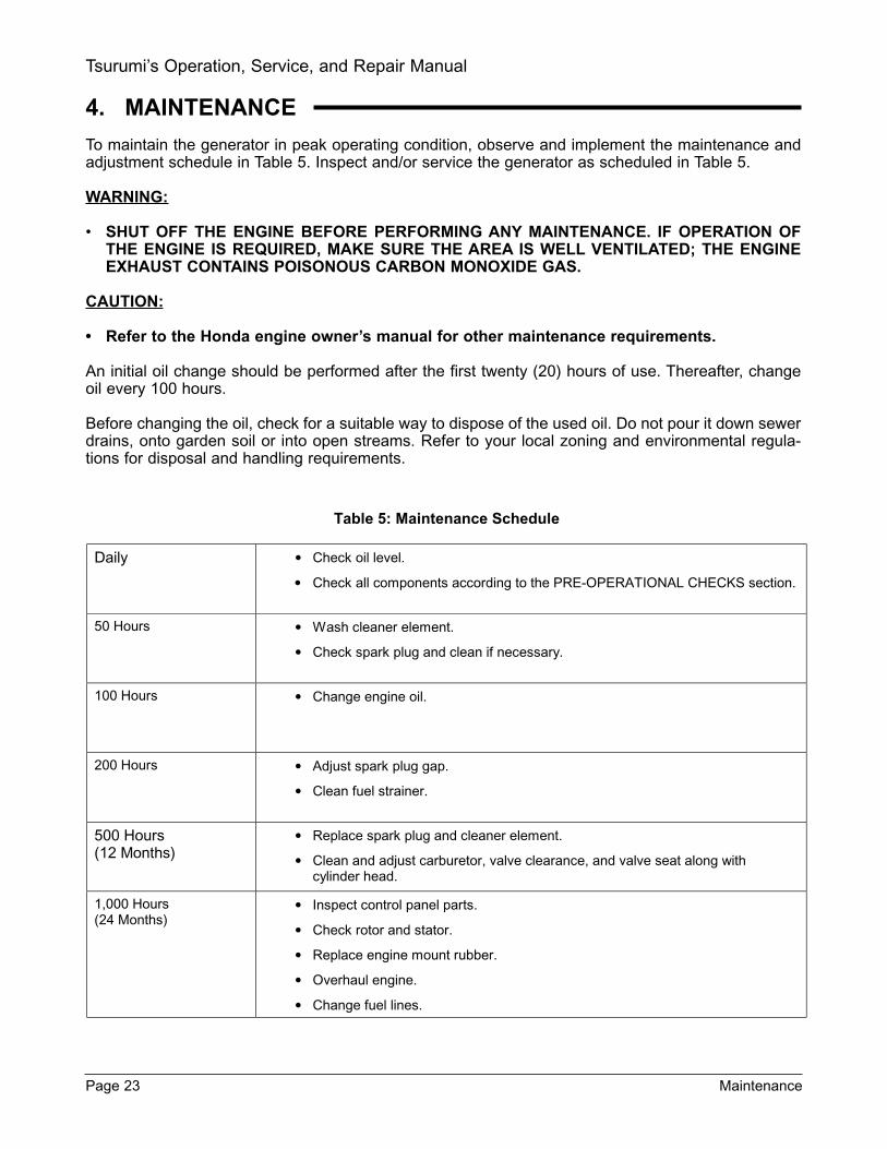
Table 5: Maintenance Schedule
Daily • Check oil level.
• Check all components according to the PRE-OPERATIONAL CHECKS section.
50 Hours • Wash cleaner element.
• Check spark plug and clean if necessary.
100 Hours • Change engine oil.
200 Hours • Adjust spark plug gap.
• Clean fuel strainer.
500 Hours (12 Months)
• Replace spark plug and cleaner element.
• Clean and adjust carburetor, valve clearance, and valve seat along with cylinder head.
1,000 Hours (24 Months)
• Inspect control panel parts.
• Check rotor and stator.
• Replace engine mount rubber.
• Overhaul engine.
• Change fuel lines.
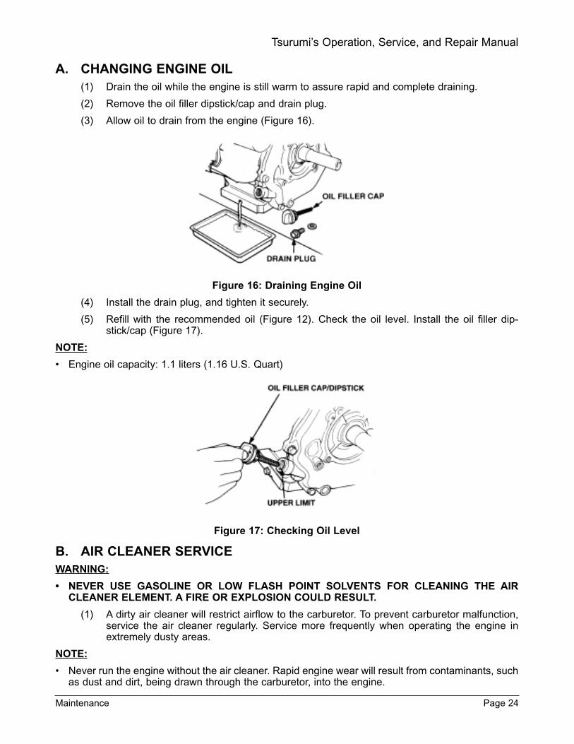
A. CHANGING ENGINE OIL(1) Drain the oil while the engine is still warm to assure rapid and complete draining.
(2) Remove the oil filler dipstick/cap and drain plug.
(3) Allow oil to drain from the engine (Figure 16).
Figure 16: Draining Engine Oil
(4) Install the drain plug, and tighten it securely.
(5) Refill with the recommended oil (Figure 12). Check the oil level. Install the oil filler dip-stick/cap (Figure 17).
NOTE:
• Engine oil capacity: 1.1 liters (1.16 U.S. Quart)
Figure 17: Checking Oil Level
B. AIR CLEANER SERVICEWARNING:
NEVER USE GASOLINE OR LOW FLASH POINT SOLVENTS FOR CLEANING THE AIRCLEANER ELEMENT. A FIRE OR EXPLOSION COULD RESULT.
(1) A dirty air cleaner will restrict airflow to the carburetor. To prevent carburetor malfunction,service the air cleaner regularly. Service more frequently when operating the engine inextremely dusty areas.
NOTE:
• Never run the engine without the air cleaner. Rapid engine wear will result from contaminants, suchas dust and dirt, being drawn through the carburetor, into the engine.
Maintenance Page 24
Tsurumi’s Operation, Service, and Repair Manual

C. SEDIMENT CUP CLEANING
WARNING:
GASOLINE IS EXTREMELY FLAMMABLE AND IS EXPLOSIVE UNDER CERTAIN CONDI-TIONS. DO NOT SMOKE OR ALLOW FLAMES OR SPARKS IN THE AREA.
AFTER INSTALLING THE SEDIMENT CUP, CHECK FOR LEAKS, AND MAKE SURE THE AREAIS FREE OF RESIDUAL FUEL SPILLS OR SEEPAGE BEFORE STARTING THE ENGINE.
(1) Turn the fuel valve to OFF.
(2) Remove (turn clockwise) the sediment cup and O-ring. Wash both parts in nonflammableor high flash point solvent.
(3) Wipe the sediment cup and O-ring dry, then reinstall.
(4) Set the fuel shutoff valve (Figure 18) to ON. Check for leaks.
Figure 18: Fuel Shutoff Valve
D. CLEANING AND ADJUSTING SPARK PLUG
Recommended spark plugs: BPR6ES (NGK)W20EPR-U (NIPPONDENSO)
To ensure proper engine operation, the spark plug must be properly gapped and free of deposits.
(1) Remove the spark plug cap.
(2) Clean any dirt from around the spark plug base.
(3) Use the proper size spark plug wrench to remove the spark plug.
WARNING:
• THE MUFFLER BECOMES VERY HOT DURING OPERATION AND REMAINS HOT FOR AWHILE AFTER STOPPING THE ENGINE. BE CAREFUL NOT TO TOUCH THE MUFFLERWHILE IT IS HOT.
Page 25 Maintenance
Tsurumi’s Operation, Service, and Repair Manual
H-2H-13

(1) Visually inspect the spark plug. Discard it if the insulator is cracked or chipped. Clean thespark plug with a wire brush if it is to be reused.
(2) Measure the plug gap with a feeler gauge. Adjust the gap as necessary by bending the sideelectrode (Figure 19).
Figure 19: Spark Plug Gap
(3) The gap should be 0.7 - 0.8 mm (0.028 - 0.031 inch) as shown.
Maintenance Page 26
Tsurumi’s Operation, Service, and Repair Manual

5. TROUBLESHOOTINGThe procedures that follow together with the fault isolation tables can be used as a guide to isolate gen-erator faults. Refer to these procedures when the engine fails to start after several attempts, or whenelectricity is not available at the receptacles.
Before testing generator components, determine if the failure is located in the generator head or in thecontrol panel. Do this by following the instructions below.
If, after following these procedures, your generator fails to start or generate electricity, contact the near-est Tsurumi generator dealer.
A. ISOLATING FAULT TO THE GENERATOR OR TO THE CONTROL PANEL
(1) This unit uses permanent magnets built into the rotor for initial excitation. Do not “flash thefields” to try to re-excite the field.
(2) Isolate the defect by disconnecting the red, white, black and blue wires from the stator (donot disconnect the two yellow wires). Then measure the AC voltage of each AC coil.
(3) Check for 120 vac (±5%) from the red-white wires and then check for 120 vac (±5%) from theblack-blue wires.
(4) If the voltage is correct, the failure is in the control panel. If the voltage is too low from eithercoil, the defect lies in the rotor, stator, or condensers.
B. MEASURING INSULATION RESISTANCE (refer to Figure 20)
(5) No AC output - Measuring Insulation Resistance
(6) Use a megger tester to test each component for prop-er insulation. An insulation resistance of 1 MΩ orgreater is normal. The insulation resistance from thefactory is at least 10 MΩ.
(7) Insulation Resistance - Stator
(a) Measure the insulation resistance betweenBLUE lead and the core.
(b) Measure the insulation resistance betweenWHITE lead and the core.
(c) Measure the insulation resistance betweenYELLOW lead and the core.
(d) Measure the insulation resistance betweenBROWN lead and the core.
(8) Insulation Resistance - Rotor
(a) Measure the insulation across one of the sol-dered terminals of the rotor and the core.
(b) Parts with insulation resistance of less than1MΩ have faulty insulation, and may causeelectric leakage and electric shock. Replacethe faulty part.
Page 27 Troubleshooting
Tsurumi’s Operation, Service, and Repair Manual
Figure 20: Measuring Resistance

C. ELECTRICAL LIMITS REFERENCE CHART
The Electrical Limits Reference Chart, Table 6, provides a ready reference to electrical component limits.
Troubleshooting Page 28
Tsurumi’s Operation, Service, and Repair Manual
D. TROUBLESHOOTING CHARTS
This section provides the instructions for generator checkout and fault isolation. The troubleshootingprocedures are presented in Table 7. The table lists typical faults, presents probable cause, and pro-vides the remedy for the majority of generator operational faults.
Page 29 Troubleshooting
Tsurumi’s Operation, Service, and Repair Manual
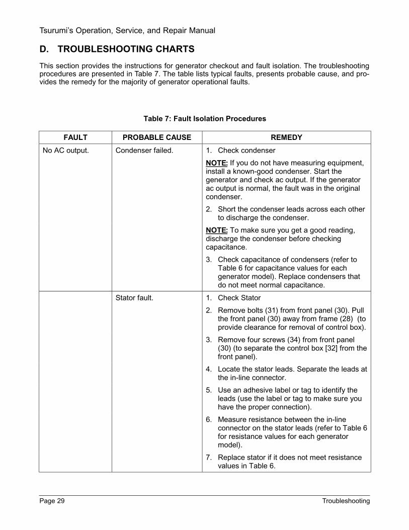
Table 7: Fault Isolation Procedures
FAULT PROBABLE CAUSE REMEDY
No AC output. Condenser failed. 1. Check condenser
If you do not have measuring equipment, install a known-good condenser. Start the generator and check ac output. If the generator ac output is normal, the fault was in the original condenser.
2. Short the condenser leads across each other to discharge the condenser.
To make sure you get a good reading, discharge the condenser before checking capacitance.
3. Check capacitance of condensers (refer to Table 6 for capacitance values for each generator model). Replace condensers that do not meet normal capacitance.
Stator fault. 1. Check Stator
2. Remove bolts (31) from front panel (30). Pull the front panel (30) away from frame (28) (to provide clearance for removal of control box).
3. Remove four screws (34) from front panel (30) (to separate the control box [32] from the front panel).
4. Locate the stator leads. Separate the leads at the in-line connector.
5. Use an adhesive label or tag to identify the leads (use the label or tag to make sure you have the proper connection).
6. Measure resistance between the in-line connector on the stator leads (refer to Table 6 for resistance values for each generator model).
7. Replace stator if it does not meet resistance values in Table 6.
NOTE:
NOTE:
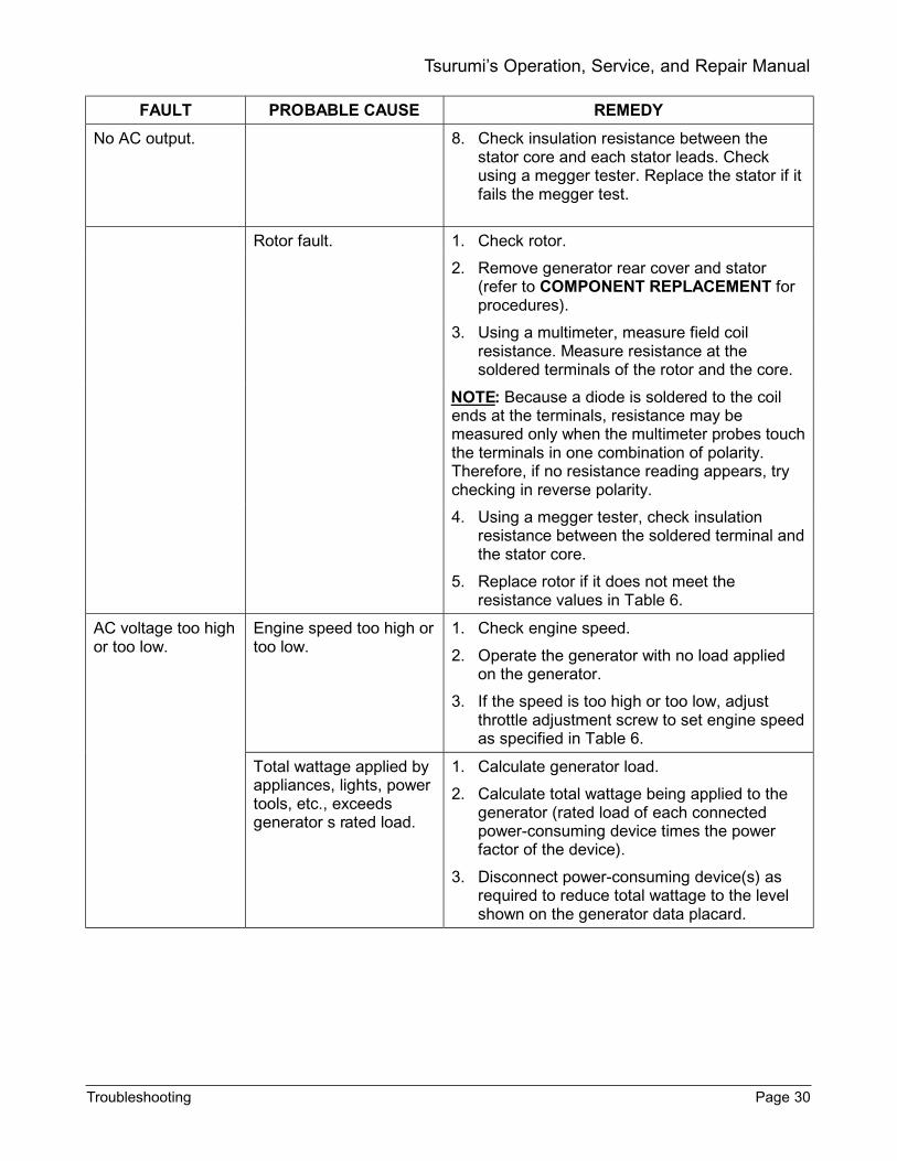
FAULT PROBABLE CAUSE REMEDY
No AC output. 8. Check insulation resistance between the stator core and each stator leads. Check using a megger tester. Replace the stator if it fails the megger test.
Rotor fault. 1. Check rotor.
2. Remove generator rear cover and stator (refer to COMPONENT REPLACEMENT for procedures).
3. Using a multimeter, measure field coil resistance. Measure resistance at the soldered terminals of the rotor and the core.
Because a diode is soldered to the coil ends at the terminals, resistance may be measured only when the multimeter probes touch the terminals in one combination of polarity. Therefore, if no resistance reading appears, try checking in reverse polarity.
4. Using a megger tester, check insulation resistance between the soldered terminal and the stator core.
5. Replace rotor if it does not meet the resistance values in Table 6.
AC voltage too high or too low.
Engine speed too high or too low.
1. Check engine speed.
2. Operate the generator with no load applied on the generator.
3. If the speed is too high or too low, adjust throttle adjustment screw to set engine speed as specified in Table 6.
Total wattage applied by appliances, lights, power tools, etc., exceeds generator s rated load.
1. Calculate generator load.
2. Calculate total wattage being applied to the generator (rated load of each connected power-consuming device times the power factor of the device).
3. Disconnect power-consuming device(s) as required to reduce total wattage to the level shown on the generator data placard.
NOTE:
Troubleshooting Page 30
Tsurumi’s Operation, Service, and Repair Manual
Page 31 Troubleshooting
Tsurumi’s Operation, Service, and Repair Manual

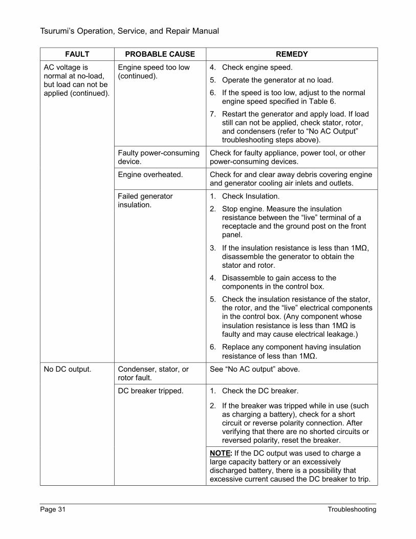
FAULT PROBABLE CAUSE REMEDY
No DC output (continued).
DC fuse blown. 1. Check DC fuse.
2. Check the fuse in the fuse holder in the control box.
3. If the fuse is blown, determine the source of the fault. Correct the fault in the DC circuit and replace the fuse (10A).
If the DC output was used to charge a large capacity battery or an excessively discharged battery, there is a possibility that excessive current caused the DC breaker to trip.
Defective wiring. 1. Check wiring.
2. Check wiring to make sure the wires are properly connected (refer to the schematic diagrams in the Wiring Diagrams section for wiring information).
3. Correct wiring as required.
Defective diode rectifier. 1. Check the diode rectifier.
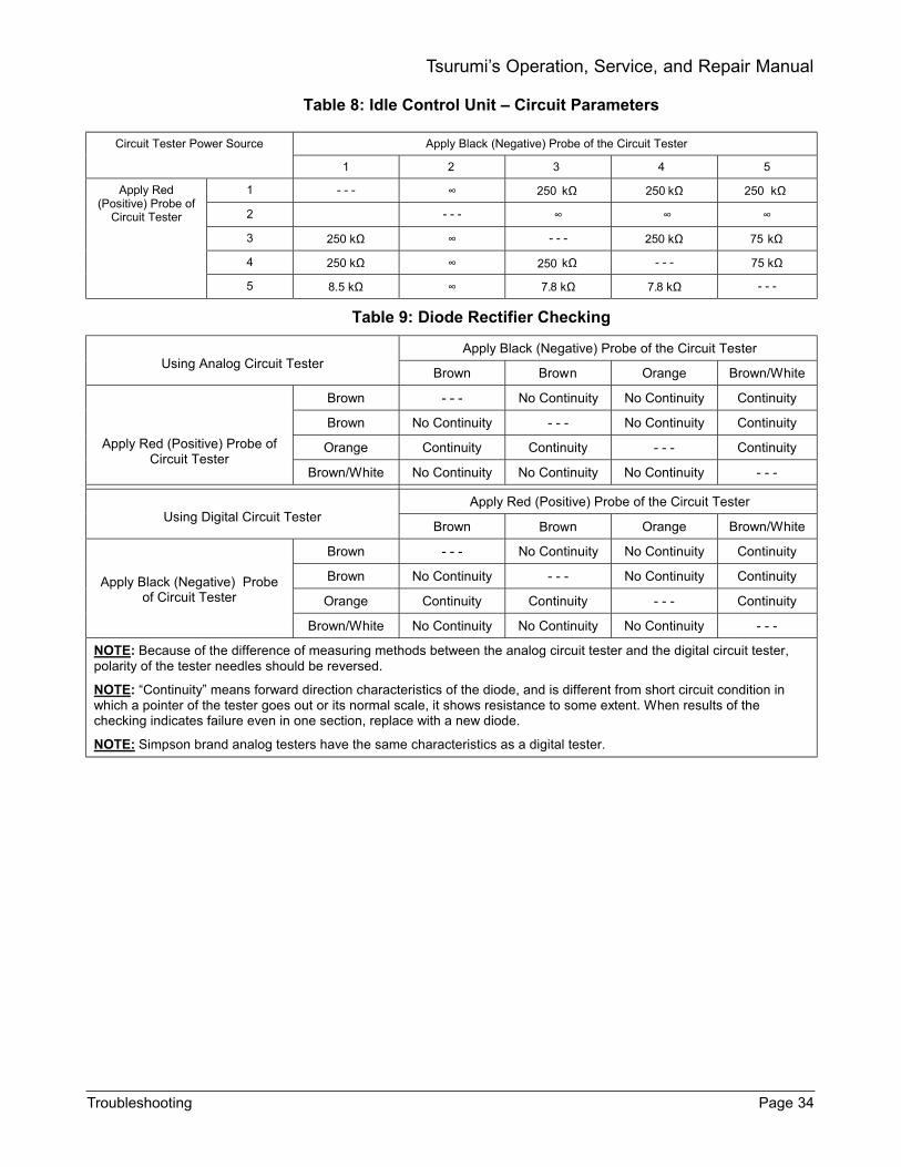
2. Remove the control panel. Remove the control box and check the diode rectifier. Using a multimeter check continuity of the diode circuitry. (Refer to Table 9 for continuity charts for both analog and digital meters.)
DC coil fault. 1. Check the diode rectifier.
2. Check resistance between leads from stator (see Table 6).
3. If resistance reading is much larger or smaller than the specified value, the DC coil of the stator is faulty.
4. Replace stator.
Engine speed does not increase when load applied.
Solenoid damaged. Check bend angle of solenoid bracket. Correct as required.
Wattage of connected appliance or electric tool exceeds rating.
1. Check rating of connected appliance or electric tool exceeds rating. Use appliance or tool having compatible rating.
2. Check the slow set RPM. Normal idling speeds are as follows:
NOTE:
Troubleshooting Page 32
Tsurumi’s Operation, Service, and Repair Manual

FAULT PROBABLE CAUSE REMEDY
Engine speed does not increase when load applied (continued).
Wattage of connected appliance or electric tool exceeds rating. (continued).
TPG-2900H-DX 1900 to 2100 RPM TPG-4300H-DX 2000 to 2200 RPM TPG-6000H-DX 2000 to 2200 RPM TPG-7000H-DXE 2000 to 2200 RPM
NO E:T The engine speeds are for a cold engine. If the engine speed adjustment screw is out of its adjustment range, move the solenoid backward.
3. Check the wiring through the coil on the idle control unit.
SINGLE VOLTAGE TYPE: Make sure that an output wire form the main coil is passing through the coil on the idle control unit.
DUAL VOLTAGE TYPE: Check to make sure that the two output wires from the main coils pass through the coil on the idle control unit in the same direction.
4. Check the idle control unit. Check resistance between the five leads.
5. Observe the terminal identification diagram below:
6. Refer to Table 6 for resistance values.
NOTE: The resistance readings in Table 6 will vary depending upon the type of circuit tester being used. Table 6 is an example of the resistance readings measured by an ordinary analog circuit tester with a 1.5-volt battery power source. It is advisable to check the resistance readings using your standard circuit tester and adjust the values accordingly.
Engine speed does not decrease when load removed.
Solenoid bracket damaged or distorted.
Check bend angle of solenoid bracket. Correct as required.
Wire leads damaged. Check to make sure two solenoid leads are securely connected.
Check wiring to idle control unit.
Check to make sure wire leads to the idle control unit are securely connected.
Solenoid failed. Check resistance between two solenoid leads (refer to Table 6) for resistance limits. If resistance is higher or lower than limits, replace solenoid.
Page 33 Troubleshooting
Tsurumi’s Operation, Service, and Repair Manual
Troubleshooting Page 34
Tsurumi’s Operation, Service, and Repair Manual
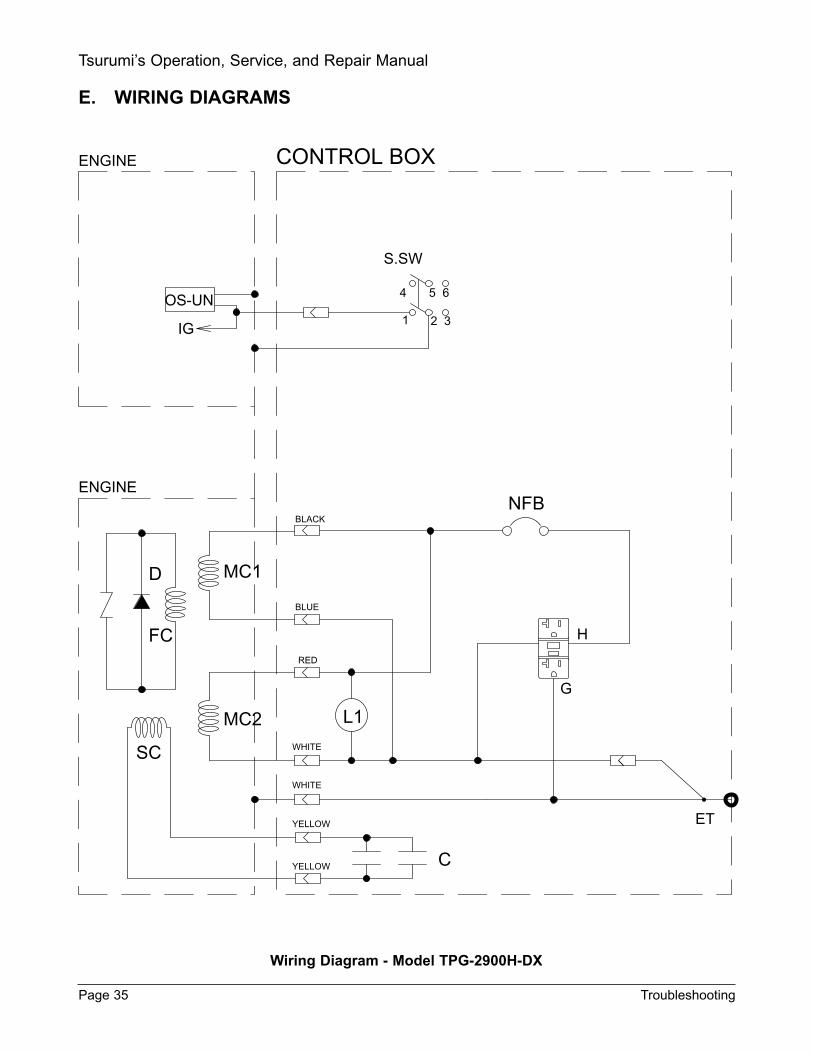
E. WIRING DIAGRAMS
Wiring Diagram - Model TPG-2900H-DX
Page 35 Troubleshooting
Tsurumi’s Operation, Service, and Repair Manual
ENGINE CONTROL BOX
OS-UN
IG
ENGINE
S.SW
4 5 6
1 2 3
NFB
H
G
ET
CYELLOW
YELLOW
WHITE
WHITE
RED
BLUE
BLACK
MC1
L1MC2
SC
FC
D
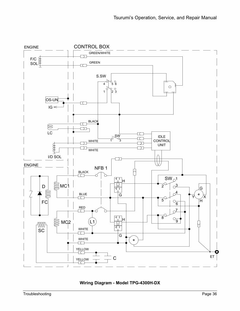
Wiring Diagram - Model TPG-4300H-DX
Troubleshooting Page 36
Tsurumi’s Operation, Service, and Repair Manual
ENGINE CONTROL BOX
F/CSOL
GREEN/WHITE
GREEN
S.SW
4 5 6
1 2 3
OS-UN
IG
LC
I/D SOL
D 2
BLUE
RED
BLACK
ENGINE
FC
MC2
MC1
SC
NFB 1
L1
H
G
G
H 89
1
4
3
6
7
5
SW
IDLECONTROL
UNIT
YELLOW C
YELLOW
SW1 3
ET
WHITE
WHITE
G
HY X
WHITE
WHITE
BLACK

Wiring Diagram - Model TPG-6000H-DX
Page 37 Troubleshooting
Tsurumi’s Operation, Service, and Repair Manual
2
BLUE
WHITE
RED
BLACK
ENGINE
ENGINE
FC
D
MC2
MC1
SC
NFB 1
L1
H
G
G
H 89
1
4
3
6
7
5
SW
NFB 2
IDLE CONTROL
UNIT
YELLOW C
YELLOW
SW1 3
I/D SOL
LC
IG
F/CSOL
CONTROL BOX
ET
WHITE
WHITE
BLACK
GREEN
GREEN/W
WHITE
G
HY X
4 5
S.SW
6
1 2 3
OS-UN

Wiring Diagram - Model TPG-7000H-DXE
Troubleshooting Page 38
Tsurumi’s Operation, Service, and Repair Manual
OS-UN
ENGINE CONTROL BOX
F/CSOL
IG
BAT STMT
M SW
CH-COLC
I/D SOL
D
FC
MC1
MC2
SC
C
G
H
NFB 2
ET
89
76
4
3
1
2
5
SW
YH
X
G
IDLE CONTROL UNIT
SW31
FCB DI
K SW
+ -
NFB 1
H
GBLUE
WHITE
RED
BLACK
ENGINE
L1
Yellow
BLUE
GREEN/WHITE
WHITE/BLACK
WHITE
GREEN
BLACK
WHITE
GREEN
GREEN/W
WHITE
Yellow
WHITE
BLACK

6. REMOVAL/INSTALLATION
Repair of the generator is limited to the replacement of failed components. This section provides theprocedures for removal of failed components and installation of replacement components.
Exploded views and other Illustrations are provided to supplement the replacement procedures.
The item numbers used in the component replacement procedures are identical to item numbers inthe Replacement Parts section. Refer to the Replacement Parts section for part numbers ofreplacement parts.
Table 10 provides torque values for the fasteners used on the generator. Tighten the fasteners totorque value shown to provide the required clamping force.
Page 39 Removal/Installation
Tsurumi’s Operation, Service, and Repair Manual
Table 10: Fastener Torque Values
Ref. No.
Fastener
Size
Model
Ft-lbs
N.m
Kg-cm
Through Bolt (M8) M8 TPG-2900H-DX 8.7 — 10.1 11.8 — 13.7 120 — 140 4
Through Bolt (M10) M10 TPG-4300H-DX TPG-6000H-DX TPG-7000H-DXE
17.4 — 18.8 23.5 — 25.5 240 — 260
Rear Cover-to-Front Cover Screws M6 TPG-2900H-DX 3.6 — 4.3 4.5 — 5.9 50 — 60 8
Rear Cover-to-Front Cover Screws M8 TPG-4300H-DX TPG-6000H-DX TPG-7000H-DXE
3.6 — 4.3 4.5 — 5.9 50 — 60
11 Brush Cover Screws M5 TPG-4300H-DX TPG-6000H-DX TPG-7000H-DXE
2.9 — 3.3 3.9 — 4.4 40 — 45
13 Front Cover-to-Engine Screws M8 ALL MODELS 8.7 — 10.1 11.8 — 13.7 120 — 140
M3 TPG-2900H-DX 1.5 — 2.2 2.0 — 2.9 20 — 30 14 Ground Wire-to-Rear Cover
M4 TPG-4300H-DX TPG-6000H-DX TPG-7000H-DXE
1.5 — 2.2 2.0 — 2.9 20 — 30
15 Rear Cover Bracket-to-Lower Muffler Support Screw
M12 TPG-4300H-DX TPG-6000H-DX TPG-7000H-DXE
21.7 — 28.9 29.4 — 39.2 300 — 400
19 Muffler Support Bracket-to-Front Cover Screw
M8 TPG-2900H-DX 8.7 — 10.8 11.8 — 13.7 120 — 140
Muffler Support Bracket-to-Rear Cover Screw
M8 TPG-4300H-DX TPG-6000H-DX TPG-7000H-DXE
8.7 — 10.8 11.8 — 13.7 120 — 140
M8 TPG-2900H-DX 8.7 — 10.8 11.8 — 13.7 120 — 140 21 Support Bar Screw
M6 TPG-4300H-DX TPG-6000H-DX TPG-7000H-DXE
8.7 — 10.8 11.8 — 13.7 120 — 140
25 Ground Wire-to-Frame Screw M5 ALL MODELS 2.9 — 3.3 3.9 — 4.4 40 — 45
26 Vibration Mount Flange Nut M8 ALL MODELS 8.7 — 10.8 11.8 — 13.7 120 — 140

A. REPLACEMENT OF BATTERY
WARNING:
DISCONNECT THE SPARK PLUG WIRE FROM THE SPARK PLUG BEFORE WORKING ONTHE GENERATOR TO PREVENT INADVERTENT ENGINE START
MAKE SURE THAT YOU DISCONNECT OR REMOVE THE BATTERY WHEN YOU DO MAIN-TENANCE. EXPLOSIVE HYDROGEN GAS MAY BE PRESENT AROUND THE BATTERY.
SPARKS FROM STATIC ELECTRICITY OR FROM HAND TOOLS CONTACTING BATTERYTERMINALS CAN CAUSE HYDROGEN GAS TO IGNITE, CAUSING INJURY AND BURNS TONEARBY PERSONNEL.
NOTE:
• Do not disassemble the battery enclosure unit unless disassembly is required to gain access to theaffected components.
• Refer to exploded view in Replacement Parts section for parts information. The item numbers in thefollowing procedure are identical to those in the Replacement Parts exploded views.
• The model TPG-7000H-DXE generator has a 12-volt DC starting system. Use a 12-volt, gardentractor-type battery as a replacement battery.
(1) Refer to Figure 21 or 22. Remove two wing nuts (79) and clips (78). Remove hold-downplate (76) and two tie-down rods (77) from battery base plate (74).
(2) Remove terminal fasteners from battery terminals.
(3) Remove battery from battery enclosure.
(4) Put replacement battery in battery enclosure.
(5) Place hold-down plate (76) on battery, being careful not to contact the battery terminals.
(6) Insert L-shaped ends of tie-down rods (77) in holes in plate (74) in base of battery enclo-sure unit.
(7) Put threaded ends of tie-down rods (77) in holes in hold-down plate (76). Install clips (78)and wing nuts (79) on threaded rods to secure battery.
(8) Connect cables to terminals on the battery.
(9) Operate generator to verify that the battery is properly connected.
Removal/Installation Page 40
Tsurumi’s Operation, Service, and Repair Manual

Figure 21: Battery Enclosure Components
B. REMOVAL/INSTALLATION OF BATTERY ENCLOSURE
WARNING:
MAKE SURE THAT YOU DISCONNECT OR REMOVE THE BATTERY WHEN YOU DO MAIN-TENANCE. EXPLOSIVE HYDROGEN GAS MAY BE PRESENT AROUND THE BATTERY.
SPARKS FROM STATIC ELECTRICITY OR FROM HAND TOOLS CONTACTING BATTERYTERMINALS CAN CAUSE THE HYROGEN GAS TO IGNITE, CAUSING INJURY AND BURNSTO NEARBY PERSONNEL.
NOTE:
• Do not remove the battery enclosure unit unless required to gain access to other components. Ifremoval of the battery support is required, remove according to the following procedures.
(1) Remove battery (refer to Replacement of Battery section).
(2) Refer to Figure 22. Remove two bolt-and-washer assemblies (82) and two self-locking nuts(83) from bottom of frame. Then remove two bolt-and-washer assemblies (80) and two self-locking nuts (81) from top of the frame.
(3) Remove entire battery enclosure unit and set aside for installation later.
NOTE:
• Do not disassemble the battery enclosure unit any further unless disassembly is required to replacedamaged battery enclosure components. If necessary, follow procedures beginning with step (4).
(4) Remove four bolt-and- washer assemblies (82) and four nuts (83) from base plate (74).
(5) Remove four bolt-and-washer assemblies (84) and four nuts (85) from shield plate (75).
Page 41 Removal/Installation
Tsurumi’s Operation, Service, and Repair Manual
12 Volt Battery
74
77, 78, 79
76
77

Figure 22: Battery Enclosure Exploded View
(6) Perform repair and/or maintenance, then proceed as follows.
(a) Align screw holes in battery base plate (74) with holes in support tubes (73). Installand tighten four bolt-and-washer assemblies (82) and four nuts (83).
(b) Align screw holes in battery shield plate (75) with holes in support tubes (73). Installand tighten four bolt-and-washer assemblies (84) and four nuts (85).
C. REPLACEMENT OF ENGINE MUFFLER (Models TPG-4300H-DX, TPG-6000H-DX, and TPG-7000H-DXE)
(1) Refer to Figure 23. Disconnect muffler from engine exhaust connection.
(2) Remove screw (H-26) securing the muffler to support bracket (18).
(3) Remove inner shield (H-23) and separate muffler from bracket (18).
(4) Remove spacer (H-37) from the muffler support bracket (18).
(5) Install shield (H-23) and replacement muffler (H-20).
(6) Install spacer (H-37) between the lugs of the support bracket (18). Use a probe (such asa Phillips screwdriver) to align spacer (H-37) with the mounting lugs in the lower mufflersupport bracket (H-19) with the muffler support bracket (18).
(7) Install bolt (H-35) and washer (H-36) in lower lug of bracket (18). Insert screw far enoughto engage the outermost screw threads in the lower support bracket (18); do not tightenscrew at this time.
(8) Install new exhaust flange gasket (H-21) and connect exhaust flange to the muffler.
(9) Tighten all fasteners and apply torque to the values shown in Table 10.
Removal/Installation Page 42
Tsurumi’s Operation, Service, and Repair Manual
79
78
82
77
74
80
81
83
73
75
8485
76
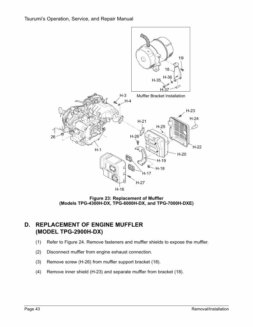
Figure 23: Replacement of Muffler(Models TPG-4300H-DX, TPG-6000H-DX, and TPG-7000H-DXE)
D. REPLACEMENT OF ENGINE MUFFLER(MODEL TPG-2900H-DX)
(1) Refer to Figure 24. Remove fasteners and muffler shields to expose the muffler.
(2) Disconnect muffler from engine exhaust connection.
(3) Remove screw (H-26) from muffler support bracket (18).
(4) Remove inner shield (H-23) and separate muffler from bracket (18).
Page 43 Removal/Installation
Tsurumi’s Operation, Service, and Repair Manual
Muffler Bracket Installation
H-37
H-35H-36
18
H-3H-4
H-1
26
H-16
H-27
H-17H-18
H-19
H-20
H-21
H-22
H-23
H-24
H-25
H-26
19
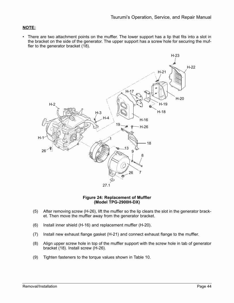
NOTE:
• There are two attachment points on the muffler. The lower support has a lip that fits into a slot inthe bracket on the side of the generator. The upper support has a screw hole for securing the muf-fler to the generator bracket (18).
Figure 24: Replacement of Muffler(Model TPG-2900H-DX)
(5) After removing screw (H-26), lift the muffler so the lip clears the slot in the generator brack-et. Then move the muffler away from the generator bracket.
(6) Install inner shield (H-16) and replacement muffler (H-20).
(7) Install new exhaust flange gasket (H-21) and connect exhaust flange to the muffler.
(8) Align upper screw hole in top of the muffler support with the screw hole in tab of generatorbracket (18). Install screw (H-26).
(9) Tighten fasteners to the torque values shown in Table 10.
Removal/Installation Page 44
Tsurumi’s Operation, Service, and Repair Manual
19H-26
181
139
8
26
27.1
H-23
H-22H-21
H-20
H-19
H-18
H-16
H-1
H-2
H-3H-4
26
H-17
7
E. REPLACEMENT OF FUEL TANK
WARNING:
DO NOT DRAIN FUEL WHILE SMOKING OR WHILE IN CLOSE PROXIMITY TO OPEN FLAME.ENGINE FUEL (GASOLINE) IS HIGHLY FLAMMABLE AND IF ACCIDENTALLY IGNITED CANCAUSE SEVERE BURNS AND DEATH.
MAKE SURE THAT YOU DISCONNECT OR REMOVE THE BATTERY BEFORE DRAININGFUEL OR ANYTIME MAINTENANCE WILL INVOLVE HANDLING ENGINE FUEL. ENGINE FUELIS EXTREMELY FLAMMABLE AND CAN CAUSE SEVERE OR FATAL BURNS IF IGNITED.
MAKE SURE THAT YOU DISCONNECT OR REMOVE THE BATTERY WHEN YOU DO MAIN-TENANCE. EXPLOSIVE HYDROGEN GAS MAY BE PRESENT AROUND THE BATTERY, ANDCAN BE IGNITED BY STATIC ELECTRICITY OR BY CONTACT WITH THE BATTERY TERMI-NALS.
BE SURE TO FOLLOW LOCAL GASOLINE HANDLING, TRANSPORT, AND FUEL DISPOSALREGULATIONS.
(1) Draining the Fuel Tank
(a) It is not necessary to drain the engine fuel tank for the majority of routine maintenancetasks. However, the tank should be drained anytime the generator will be stored orwhen the fuel tank must be removed for maintenance.
(b) If the engine can be started, start the engine and close the fuel tank shutoff valve (H-13) (refer to Figure 25). Let the engine operate until it is starved of fuel and stops. Bydoing so, residual fuel in the fuel lines and carburetor will be reduced to a minimum.
(c) Disconnect the fuel hose from the fuel tank shutoff valve (H-13) (refer to Figure 26).
(d) Connect a drain hose to the fuel tank shutoff valve and place the free end of the tubein an approved gasoline container. The container should have a capacity of 4.5 gal-lons minimum.
(e) Open the fuel shutoff valve (H-13) and allow the fuel to drain from the tank.
(f) Tighten the cap on the fuel container.
Page 45 Removal/Installation
Tsurumi’s Operation, Service, and Repair Manual

Figure 25: Fuel Shutoff Valve (Shown in CLOSED Position)
WARNING:
DO NOT DRAIN FUEL WHILE SMOKING OR WHILE IN CLOSE PROXIMITY TO OPEN FLAME.ENGINE FUEL (GASOLINE) IS HIGHLY FLAMMABLE AND IF ACCIDENTALLY IGNITED CANCAUSE SEVERE BURNS AND DEATH.
MAKE SURE THAT YOU DISCONNECT OR REMOVE THE BATTERY BEFORE DRAINING FUELOR WHENEVER MAINTENANCE WILL INVOLVE HANDLING ENGINE FUEL. ENGINE FUEL ISEXTREMELY FLAMMABLE AND CAN CAUSE SEVERE OR FATAL BURNS IF IGNITED.
MAKE SURE THAT YOU DISCONNECT OR REMOVE THE BATTERY WHEN YOU DO MAIN-TENANCE. EXPLOSIVE HYDROGEN GAS MAY BE PRESENT AROUND THE BATTERY.
SPARKS FROM STATIC ELECTRICITY OR FROM HAND TOOLS CONTACTING BATTERYTERMINALS CAN CAUSE THE HYROGEN GAS TO EXPLODE, CAUSING INJURY ANDBURNS TO NEARBY PERSONNEL.
NOTE:
• Refer to exploded view in Replacement Parts section for parts information. The item numbers inthe following procedure are identical to those in the Replacement Parts exploded views.
(2) Removal of Fuel Tank
(a) Drain fuel from fuel tank (refer to Draining of the Fuel Tank).
(b) Remove two bolts (21) from support bar (22) on the muffler side of the generator.
(c) Remove two bolts (H-9) and washers (H-10) from the fuel tank (H-5).
(d) Slip the flange on the opposite side of the fuel tank out of the channel in the frontpanel (29).
(e) If the fuel tank is being replaced, remove the fuel shutoff valve (H-13), two rubberbushings (H-12), and two bushings (H-11).
Removal/Installation Page 46
Tsurumi’s Operation, Service, and Repair Manual
H-2H-13
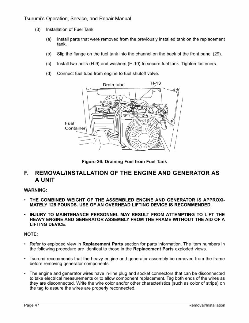
(3) Installation of Fuel Tank.
(a) Install parts that were removed from the previously installed tank on the replacementtank.
(b) Slip the flange on the fuel tank into the channel on the back of the front panel (29).
(c) Install two bolts (H-9) and washers (H-10) to secure fuel tank. Tighten fasteners.
(d) Connect fuel tube from engine to fuel shutoff valve.
Figure 26: Draining Fuel from Fuel Tank
F. REMOVAL/INSTALLATION OF THE ENGINE AND GENERATOR ASA UNIT
WARNING:
• THE COMBINED WEIGHT OF THE ASSEMBLED ENGINE AND GENERATOR IS APPROXI-MATELY 125 POUNDS. USE OF AN OVERHEAD LIFTING DEVICE IS RECOMMENDED.
INJURY TO MAINTENANCE PERSONNEL MAY RESULT FROM ATTEMPTING TO LIFT THEHEAVY ENGINE AND GENERATOR ASSEMBLY FROM THE FRAME WITHOUT THE AID OF ALIFTING DEVICE.
NOTE:
• Refer to exploded view in Replacement Parts section for parts information. The item numbers inthe following procedure are identical to those in the Replacement Parts exploded views.
• Tsurumi recommends that the heavy engine and generator assembly be removed from the framebefore removing generator components.
• The engine and generator wires have in-line plug and socket connectors that can be disconnectedto take electrical measurements or to allow component replacement. Tag both ends of the wires asthey are disconnected. Write the wire color and/or other characteristics (such as color of stripe) onthe tag to assure the wires are properly reconnected.
Page 47 Removal/Installation
Tsurumi’s Operation, Service, and Repair Manual
Drain tube H-13
FuelContainer
(1) In order to gain access for removal of the generator and engine as a unit, the fuel tank willfirst need to be drained and removed. (Refer to the procedures in Draining of the FuelTank and to Replacement of the Fuel Tank.)
(2) In addition, the front panel and control box will need to be removed as covered in the pro-cedures that follow.
(3) Tag and disconnect engine wiring from the front panel (29). The engine wiring is in thecable that exits the control box (32).
(4) Remove two screws (11) from the generator brush cover (10). Tag and disconnect gener-ator wiring.
NOTE:
• Only Models TPG-4300H-DX, TPG-6000H-DX, and TPG-7000H-DXE have a wiring access plate.
(5) Separate the flexible tube (12) from the rear cover (7). Pull generator wires out of theaccess opening in the rear cover (7).
(6) Disconnect engine wiring from the generator as required.
(7) Remove four flanged bolts (21) to remove support bar (22).
(8) With engine and generator wiring disconnected, the front panel can now be removed.
(9) Remove four frame bolts (31) from front panel (29).
(10) Remove flanged nuts (26) from generator vibration mounts (27.2).
(11) Remove four flanged nuts (26) from four engine vibration mounts (27). Remove spacers(27.1).
(12) Lift the engine and generator assembly from the frame (28) using an overhead-liftingdevice.
CAUTION:
Be sure to protect the engine from damage. Put cushioning material between the engine andthe workbench. Use wooden blocks to support the engine and generator assembly duringremoval and installation of generator components.
(13) Set engine and generator assembly on the workbench. Position the assembly with the gen-erator end facing up; use support blocks to steady the assembly.
(14) If you are replacing the stator (6), refer to Replacement of Generator Stator.
(15) If you are replacing the rotor (2), refer to Replacement of Rotor.
(16) If your are replacing the rotor bearing (3), refer to Replacement of Rotor Bearing.
(17) If you are replacing the engine (H-1), refer to Replacement of Engine.
(18) Install front cover (1) with cooling slots down. Align screw holes and install four bolt andwasher assemblies (13).
(19) Tighten bolt and washer assemblies (13) to the torque values shown in Table 10.
Removal/Installation Page 48
Tsurumi’s Operation, Service, and Repair Manual

NOTE:
• Model TPG-2900H-DX uses four vibration mounts of two different part numbers. Two vibrationmounts of one part number are used to support the generator. Two vibration mounts of another partnumber are used to support the engine. Refer to the Replacement Parts section for part numbersand location.
• Model TPG-4300H-DX uses six vibration mounts of the same part number to support both theengine and the generator. Refer to the Replacement Parts section for part numbers and location.
• Models TPG-6000H-DX and TPG-7000H-DXE use six vibration mounts of two different part num-bers. Two vibration mounts of one part number are used to support the generator. Four vibrationmounts of another part number are used to support the engine. Refer to the Replacement Partssection for part numbers and location.
(20) If vibration mounts (27 and 27.2) are being replaced, first install the mounts on frame (28)as follows:
(a) Install engine vibration mounts (27) and secure to frame (28) with flanged nuts (26).
(b) Install generator vibration mounts (27.2) and secure to frame (28) with flanged nuts(26).
(c) When used, install two spacers (27.1) over the two generator vibration mounts (27.2).
(21) Install assembled engine and generator as a unit over vibration mounts (27 and 27.2).
(22) Install flanged nuts (26) on the engine vibration mounts (27).
(23) Connect engine wiring from the front panel (29) according to the tags attached to the wiresduring disassembly. (The engine wiring is in the cable that exits the control box (32).)
(24) Install the brush cover (10) and secure with two screws (11).
NOTE:
• A wiring access cover (brush cover) is provided only on Models TPG-4300H-DX, TPG-6000H-DX,and TPG-7000H-DXE.
(25) Slip the flexible tube (12) in the hole in the rear cover (7) making sure the groove in thetube is seated in the hole in control box (32) and rear cover (7).
(26) Connect engine wiring to the generator as required. (Refer to the Wiring Diagrams section.)
(27) Install front panel and control box (see Removal/Installation of Front Panel and ControlBox, fuel tank (see Replacement of Fuel Tank), and engine muffler (see Replacement ofEngine Muffler).
(28) Install four flanged bolts (21) to secure support bars (22).
Page 49 Removal/Installation
Tsurumi’s Operation, Service, and Repair Manual
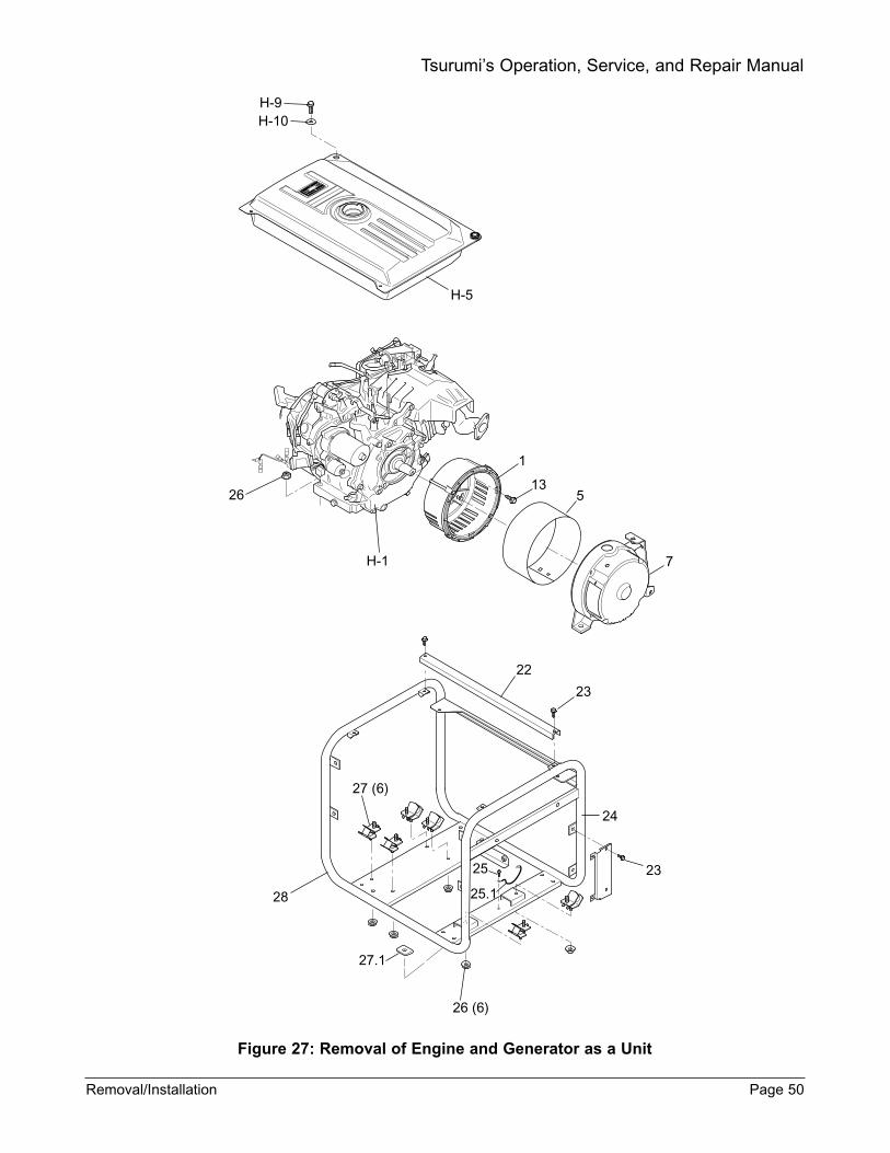
Figure 27: Removal of Engine and Generator as a Unit
Removal/Installation Page 50
Tsurumi’s Operation, Service, and Repair Manual
H-9H-10
H-5
H-1
26
22
23
24
2325
25.1
27 (6)
28
26 (6)
27.1
1
135
7

G. REPLACEMENT OF GENERATOR STATOR
NOTE:
• Refer to exploded view in Replacement Parts section for parts information. The item numbers inthe following procedure are identical to those in the Replacement Parts exploded views.
(1) Drain and remove fuel tank (H-5) (refer to Replacement of Fuel Tank for removal instruc-tions).
(2) Remove the muffler (H-20) and shields to gain access to generator (refer to Replacementof Muffler for removal instructions).
(3) Remove muffler support bracket (18), (Figure 23) as follows:
(a) For Model TPG-2900H-DX. Remove bolt and washer assembly (19), (Figure 24).Remove flanged nut (26) securing bracket (18) to rear cover (7).
(b) For Model TPG-4300H-DX, TPG-6000H-DX, and TPG-7000H-DXE. Remove twobolt and washer assemblies (19), (Figure 23) securing bracket (18) to rear cover (7).
(4) Remove the flexible tube (12), (Figure 28) from the rear cover (7). Pull the wires out of theaccess opening in the rear cover. Tag and disconnect the wires.
Figure 28: Replacement of Stator
(5) Remove bolts (8) and washers (9). Use a plastic, rubber, or other soft-faced hammer to loosenthe rear cover (7). Alternately tap upward on the generator mounting lugs until the rear cover canbe removed by hand.
(6) With the rear cover loosened, carefully position the rear cover so you have access toground screw and washer assembly (14).
Page 51 Removal/Installation
Tsurumi’s Operation, Service, and Repair Manual
1
213
6
514
12
11
4
3
10
9
8
H-1
7
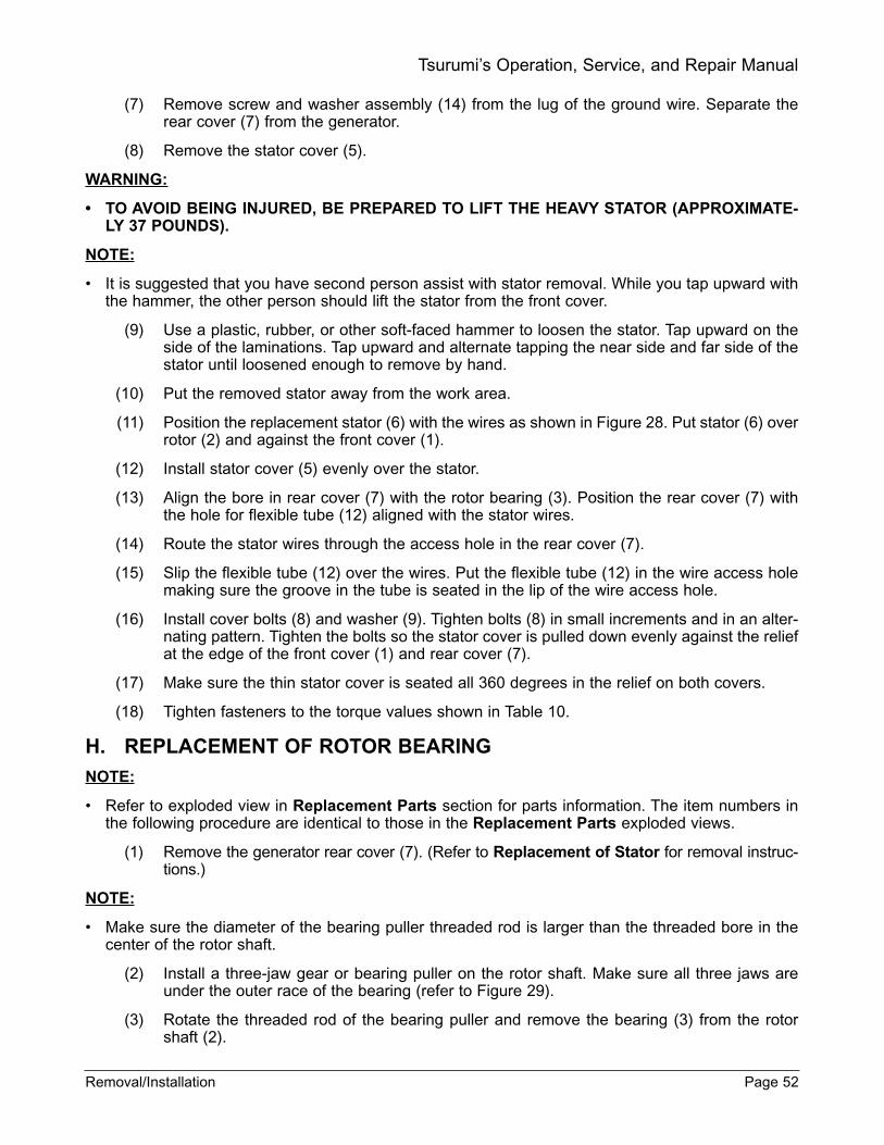
(7) Remove screw and washer assembly (14) from the lug of the ground wire. Separate therear cover (7) from the generator.
(8) Remove the stator cover (5).
WARNING:
TO AVOID BEING INJURED, BE PREPARED TO LIFT THE HEAVY STATOR (APPROXIMATE-LY 37 POUNDS).
NOTE:
• It is suggested that you have second person assist with stator removal. While you tap upward withthe hammer, the other person should lift the stator from the front cover.
(9) Use a plastic, rubber, or other soft-faced hammer to loosen the stator. Tap upward on theside of the laminations. Tap upward and alternate tapping the near side and far side of thestator until loosened enough to remove by hand.
(10) Put the removed stator away from the work area.
(11) Position the replacement stator (6) with the wires as shown in Figure 28. Put stator (6) overrotor (2) and against the front cover (1).
(12) Install stator cover (5) evenly over the stator.
(13) Align the bore in rear cover (7) with the rotor bearing (3). Position the rear cover (7) withthe hole for flexible tube (12) aligned with the stator wires.
(14) Route the stator wires through the access hole in the rear cover (7).
(15) Slip the flexible tube (12) over the wires. Put the flexible tube (12) in the wire access holemaking sure the groove in the tube is seated in the lip of the wire access hole.
(16) Install cover bolts (8) and washer (9). Tighten bolts (8) in small increments and in an alter-nating pattern. Tighten the bolts so the stator cover is pulled down evenly against the reliefat the edge of the front cover (1) and rear cover (7).
(17) Make sure the thin stator cover is seated all 360 degrees in the relief on both covers.
(18) Tighten fasteners to the torque values shown in Table 10.
H. REPLACEMENT OF ROTOR BEARING
NOTE:
• Refer to exploded view in Replacement Parts section for parts information. The item numbers inthe following procedure are identical to those in the Replacement Parts exploded views.
(1) Remove the generator rear cover (7). (Refer to Replacement of Stator for removal instruc-tions.)
NOTE:
• Make sure the diameter of the bearing puller threaded rod is larger than the threaded bore in thecenter of the rotor shaft.
(2) Install a three-jaw gear or bearing puller on the rotor shaft. Make sure all three jaws areunder the outer race of the bearing (refer to Figure 29).
(3) Rotate the threaded rod of the bearing puller and remove the bearing (3) from the rotorshaft (2).
Removal/Installation Page 52
Tsurumi’s Operation, Service, and Repair Manual
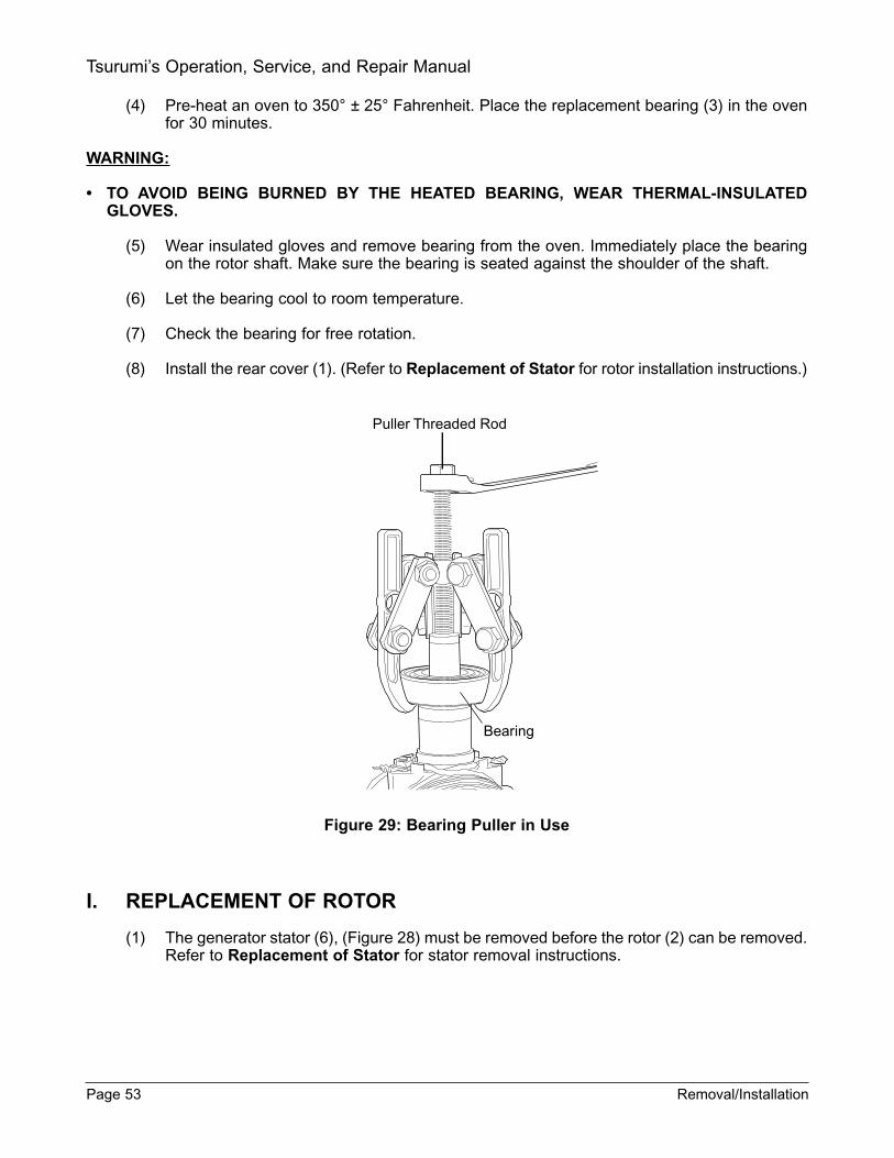
(4) Pre-heat an oven to 350° ± 25° Fahrenheit. Place the replacement bearing (3) in the ovenfor 30 minutes.
WARNING:
TO AVOID BEING BURNED BY THE HEATED BEARING, WEAR THERMAL-INSULATEDGLOVES.
(5) Wear insulated gloves and remove bearing from the oven. Immediately place the bearingon the rotor shaft. Make sure the bearing is seated against the shoulder of the shaft.
(6) Let the bearing cool to room temperature.
(7) Check the bearing for free rotation.
(8) Install the rear cover (1). (Refer to Replacement of Stator for rotor installation instructions.)
Figure 29: Bearing Puller in Use
I. REPLACEMENT OF ROTOR
(1) The generator stator (6), (Figure 28) must be removed before the rotor (2) can be removed.Refer to Replacement of Stator for stator removal instructions.
Page 53 Removal/Installation
Tsurumi’s Operation, Service, and Repair Manual
Puller Threaded Rod
Bearing
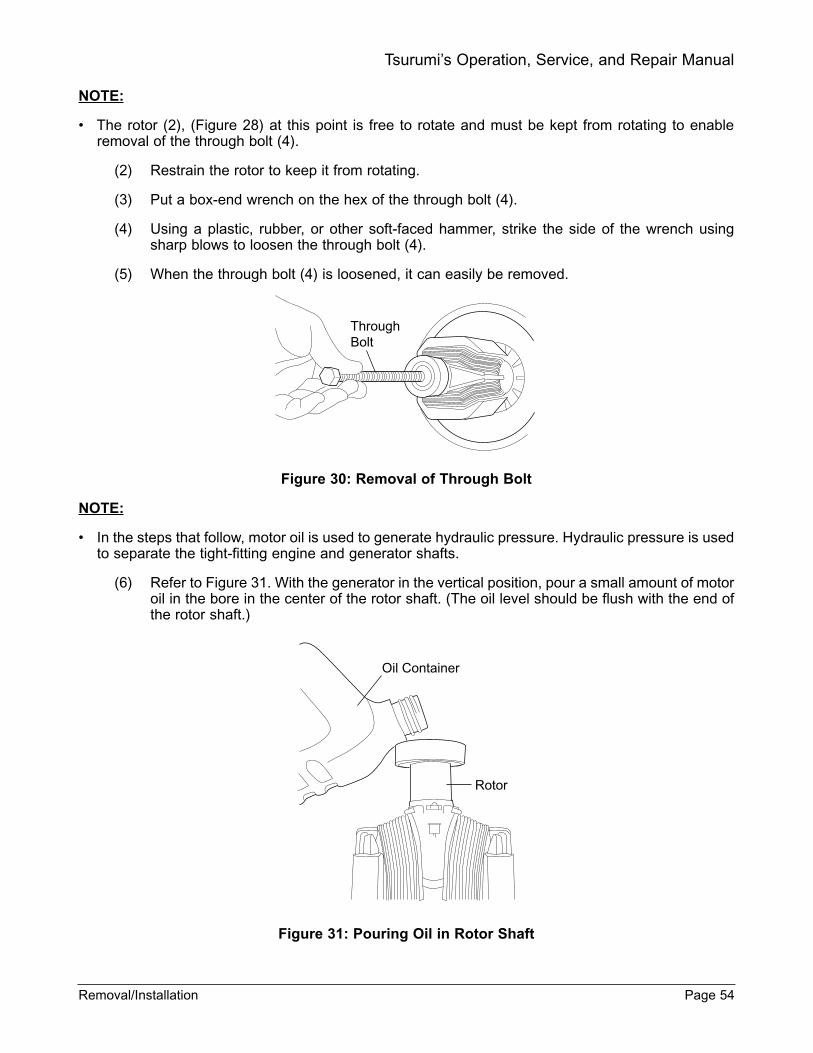
NOTE:
• The rotor (2), (Figure 28) at this point is free to rotate and must be kept from rotating to enableremoval of the through bolt (4).
(2) Restrain the rotor to keep it from rotating.
(3) Put a box-end wrench on the hex of the through bolt (4).
(4) Using a plastic, rubber, or other soft-faced hammer, strike the side of the wrench usingsharp blows to loosen the through bolt (4).
(5) When the through bolt (4) is loosened, it can easily be removed.
Figure 30: Removal of Through Bolt
NOTE:
• In the steps that follow, motor oil is used to generate hydraulic pressure. Hydraulic pressure is usedto separate the tight-fitting engine and generator shafts.
(6) Refer to Figure 31. With the generator in the vertical position, pour a small amount of motoroil in the bore in the center of the rotor shaft. (The oil level should be flush with the end ofthe rotor shaft.)
Figure 31: Pouring Oil in Rotor Shaft
Removal/Installation Page 54
Tsurumi’s Operation, Service, and Repair Manual
ThroughBolt
Oil Container
Rotor

(7) Refer to Figure 32. Wrap electrical tape around the threads of a bolt to form a seal; do notput tape on the first two threads of the bolt.
(a) For Models TPG-4300H-DX, TPG-6000H-DX, and TPG-7000H-DXE, use a 12mm,1.5-pitch bolt with a 25mm thread length.
(b) For Model TPG-2900H-DX, use a 10mm, 1.5 pitch bolt with a 25 mm thread length.
Figure 32: Wrapping Bolt with Tape
NOTE:
• Have shop towels available to wipe up spilled oil.
(8) Install the bolt in the center of the rotor shaft refer (to Figure 33). Turn the bolt into the shaft;the force required to turn the bolt will increase as the pressure increases.
Page 55 Removal/Installation
Tsurumi’s Operation, Service, and Repair Manual
Wind tape on bolt

Figure 33: Tightening of Through Bolt for Separation of Engine and Generator
(9) When the shafts separate, place the rotor on a shop towel and let the oil drain from theshaft. Wipe up oil that drained into the front cover.
(10) The front cover may remain installed unless it is damaged or the engine is being replaced.To remove the front cover, remove four bolt and washer assemblies (13), (Figure 34).
Figure 34: Front Cover Bolts
(11) If the front cover was removed, position front cover with cooling air slots on the bottom ofthe generator. Secure with four bolt and washer assemblies (13). Tighten to the torque val-ues shown in Table 10.
(12) Complete assembly of the generator as follows:
(a) Install rotor (2). (Refer to Replacement of Rotor for rotor installation procedures.)
(b) If bearing (3) was removed, install according to the bearing installation procedures inReplacement of Rotor Bearing.
(c) Install the stator (6), stator cover (5), and rear cover. (Refer to Replacement ofGenerator Stator for installation procedures.)
Removal/Installation Page 56
Tsurumi’s Operation, Service, and Repair Manual
Taped Bolt
Engine To Generator Bolts (4)
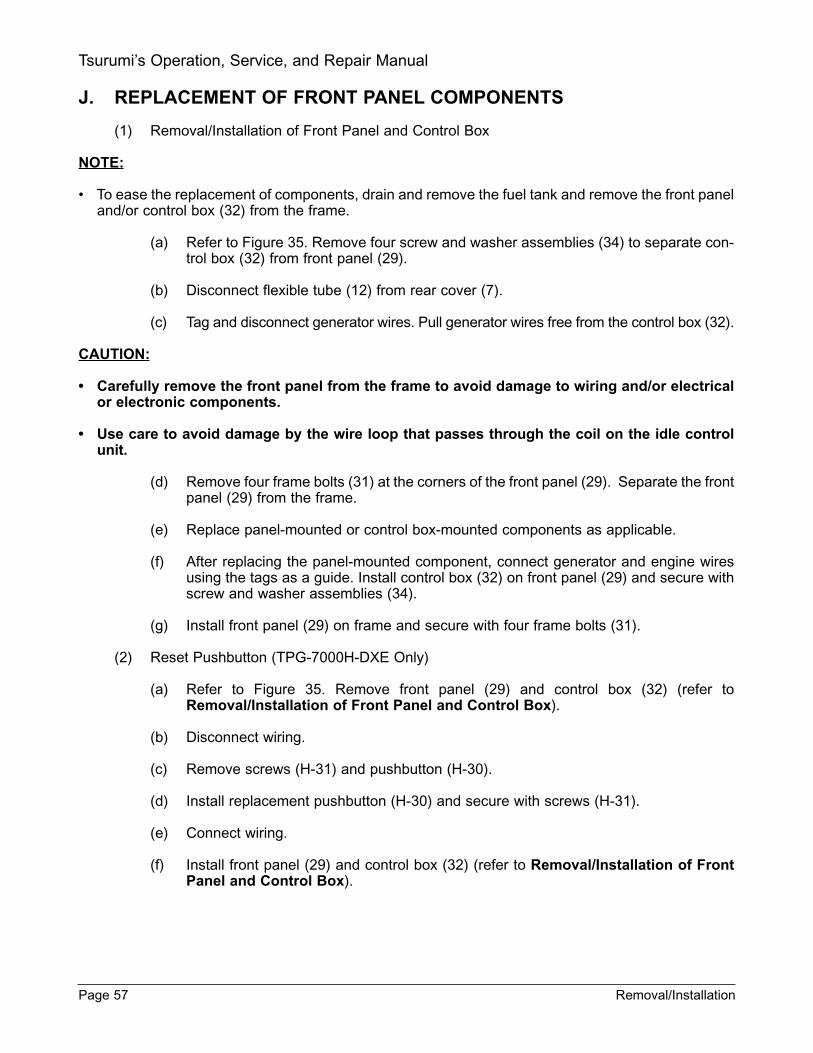
J. REPLACEMENT OF FRONT PANEL COMPONENTS
(1) Removal/Installation of Front Panel and Control Box
NOTE:
• To ease the replacement of components, drain and remove the fuel tank and remove the front paneland/or control box (32) from the frame.
(a) Refer to Figure 35. Remove four screw and washer assemblies (34) to separate con-trol box (32) from front panel (29).
(b) Disconnect flexible tube (12) from rear cover (7).
(c) Tag and disconnect generator wires. Pull generator wires free from the control box (32).
CAUTION:
Carefully remove the front panel from the frame to avoid damage to wiring and/or electricalor electronic components.
Use care to avoid damage by the wire loop that passes through the coil on the idle controlunit.
(d) Remove four frame bolts (31) at the corners of the front panel (29). Separate the frontpanel (29) from the frame.
(e) Replace panel-mounted or control box-mounted components as applicable.
(f) After replacing the panel-mounted component, connect generator and engine wiresusing the tags as a guide. Install control box (32) on front panel (29) and secure withscrew and washer assemblies (34).
(g) Install front panel (29) on frame and secure with four frame bolts (31).
(2) Reset Pushbutton (TPG-7000H-DXE Only)
(a) Refer to Figure 35. Remove front panel (29) and control box (32) (refer toRemoval/Installation of Front Panel and Control Box).
(b) Disconnect wiring.
(c) Remove screws (H-31) and pushbutton (H-30).
(d) Install replacement pushbutton (H-30) and secure with screws (H-31).
(e) Connect wiring.
(f) Install front panel (29) and control box (32) (refer to Removal/Installation of FrontPanel and Control Box).
Page 57 Removal/Installation
Tsurumi’s Operation, Service, and Repair Manual

Figure 35: Front Panel and Control Box Components(Model TPG-7000H-DXE Shown)
(3) Overload Protector (TPG-7000H-DXE)
(a) Refer to Figure 35. Remove front panel (29) and control box (32) (refer toRemoval/Installation of Front Panel and Control Box).
(b) Remove overload protector (H-33) from its connector.
(c) Install replacement overload protector (H-33) in its connector.
(d) Install front panel (29) and control box (32) (refer to Removal/Installation of FrontPanel and Control Box).
(4) DC Fuse (TPG-7000H-DXE)
(a) Refer to Figure 35. Remove front panel (29) and control box (32) (refer toRemoval/Installation of Front Panel and Control Box).
(b) Remove fuse (H-32) from its fuse holder.
(c) Install replacement fuse (H-32) in its fuse holder.
(d) Install front panel (29) and control box (32) (refer to Removal/Installation of FrontPanel and Control Box).
Removal/Installation Page 58
Tsurumi’s Operation, Service, and Repair Manual
H-32
H-33
72
32,33
H-31
H-27
3840
42
42
64
65
63
43
43
6667
68
69
70
H-30
5154
47
49
5758
59 60
6162
58
30
30.1
31
34
H-28
H-29
39
45
464152,53 55,56
48 50
72.1

(5) Engine Start (Key) Switch (TPG-7000H-DXE)
(a) Refer to Figure 35. Remove ring nut (H-28) and fiber washer (H-29). Pull switch (H-27) from backside of front panel (29).
(b) Separate switch from its connector.
(c) Align notch in panel with the key on the switch. Install replacement switch (35) in backside of front panel (29).
(d) Install fiber washer (H-29) and ring nut (H-28). Tighten ring nut (H-28).
(e) Connect switch with mating connector.
(6) Engine Switch (Models TPG-2900H-DX, TPG-4300H-DX and TPG-6000H-DX)
(a) Refer to Figure 36. Remove front panel (29) and control box (32) (refer toRemoval/Installation of Front Panel and Control Box).
(b) Disconnect wiring.
(c) Connect wiring and install replacement switch (35) in back of front panel (29). Securewith screw and washer assemblies (36).
(d) Install front panel (29) and control box (32) (refer to Removal/Installation of FrontPanel and Control Box).
(7) Pilot Lamp (ALL MODELS)
(a) Refer to Figure 36. Remove front panel (29) and control box (32) (refer toRemoval/Installation of Front Panel and Control Box).
(b) Disconnect wire from pilot light (46). Squeeze inward on tab to release the pilot light(46) from the panel (30).
(c) Install replacement pilot light (46) from front of panel. Install pilot light (46) until thetab snaps into place.
(d) Connect the wire to the pilot light (46).
(e) Install front panel (29) and control box (32) (refer to Removal/Installation of FrontPanel and Control Box).
(8) Circuit Breaker (51)
(a) Refer to Figure 36. Remove front panel (29) and control box (32) (refer toRemoval/Installation of Front Panel and Control Box).
(b) For breaker (51), remove two screw and washer assemblies (52) and washers (53).
(c) Disconnect wiring.
(d) Connect wiring and install replacement breaker (51) in back of front panel (29).Secure with two screw and washer assemblies (52) and two washers (53).
(9) Circuit Breaker (54)
(a) For breaker (54), remove four screw and washer assemblies (55) and washers (56).
(b) Disconnect wiring.
Page 59 Removal/Installation
Tsurumi’s Operation, Service, and Repair Manual
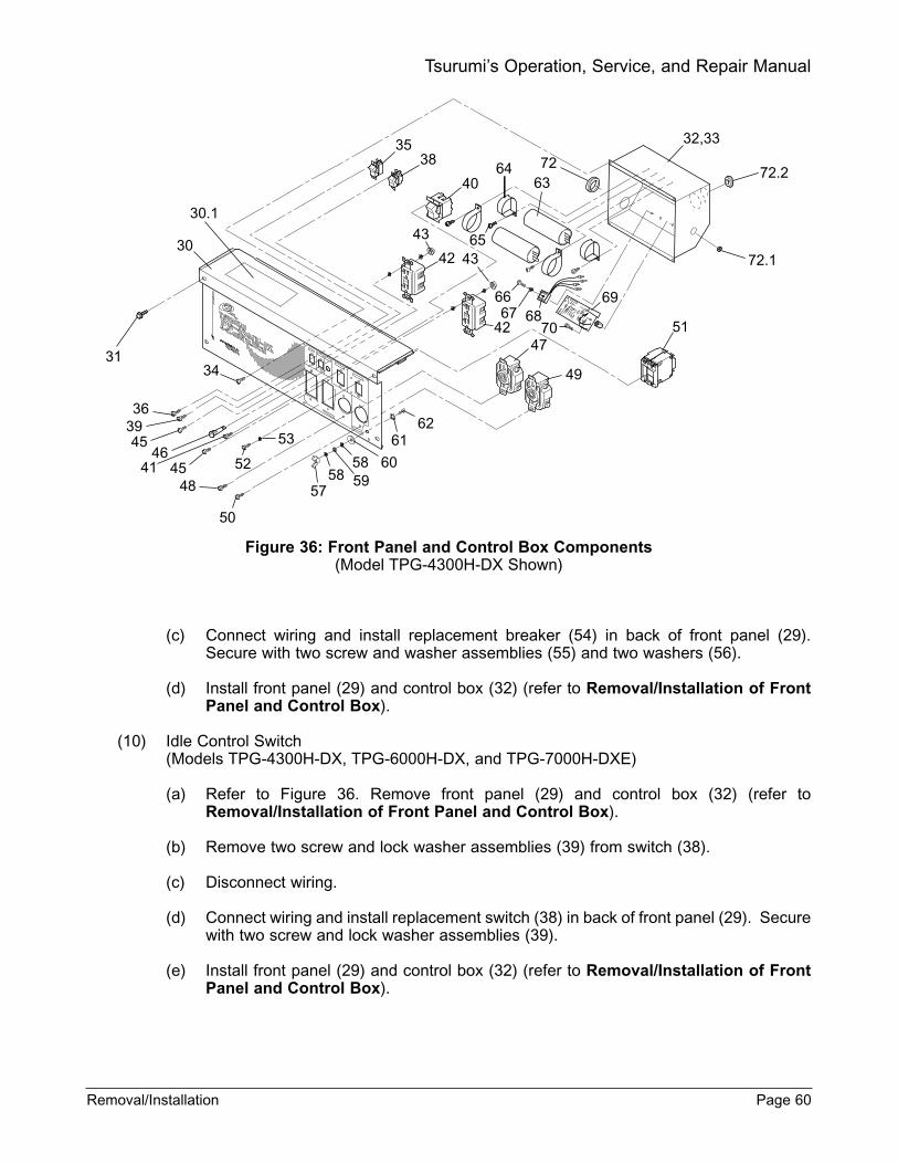
Figure 36: Front Panel and Control Box Components(Model TPG-4300H-DX Shown)
(c) Connect wiring and install replacement breaker (54) in back of front panel (29).Secure with two screw and washer assemblies (55) and two washers (56).
(d) Install front panel (29) and control box (32) (refer to Removal/Installation of FrontPanel and Control Box).
(10) Idle Control Switch (Models TPG-4300H-DX, TPG-6000H-DX, and TPG-7000H-DXE)
(a) Refer to Figure 36. Remove front panel (29) and control box (32) (refer toRemoval/Installation of Front Panel and Control Box).
(b) Remove two screw and lock washer assemblies (39) from switch (38).
(c) Disconnect wiring.
(d) Connect wiring and install replacement switch (38) in back of front panel (29). Securewith two screw and lock washer assemblies (39).
(e) Install front panel (29) and control box (32) (refer to Removal/Installation of FrontPanel and Control Box).
Removal/Installation Page 60
Tsurumi’s Operation, Service, and Repair Manual
32,333538
40
43
646372
51
49
47
43
69
7068
65
6766
42
4230
30.1
3134
363945
4641 45 52
53
48
50
57
605858 59
6162
72.2
72.1
(11) Full-power Switch
(Models TPG-4300H-DX, TPG-6000H-DX, and TPG-7000H-DXE)
(a) Refer to Figure 36. Remove front panel (29) and control box (32) (refer toRemoval/Installation of Front Panel and Control Box).
(b) Remove two screw and lock washer assemblies (41) from switch (40).
(c) Disconnect wiring.
(d) Connect wiring and install replacement switch (40) in back of front panel (29) andsecure with two screw and lock washer assemblies (41).
(e) Install front panel (29) and control box (32) (refer to Removal/Installation of FrontPanel and Control Box).
(12) Twist Lock Receptacles
(f) Refer to Figure 36. Install front panel (29) and control box (32) (refer toRemoval/Installation of Front Panel and Control Box).
(g) For receptacle (47), remove two screw and lock washer assemblies (48).
(h) Disconnect wiring.
(i) Connect wiring and install replacement receptacle (47) in back of front panel (29) andsecure with two screw and lock washer assemblies (48).
(j) For receptacle (49), remove two screw and lock washer assemblies (50).
(k) Disconnect wiring.
(l) Connect wiring and install replacement receptacle (49) in back of front panel (29) andsecure with two screw and lock washer assemblies (50).
(m) Install front panel (29) and control box (32) (refer to Removal/Installation of FrontPanel and Control Box).
(13) GFCI Receptacles
(n) Refer to Figure 36. Remove front panel (29) and control box (32) (refer toRemoval/Installation of Front Panel and Control Box).
(o) Remove two screw and lock washer assemblies (45) and receptacle (42).
(p) Disconnect wiring and remove receptacle.
(q) Connect wiring to replacement receptacle.
(r) Install two screw and washer assemblies (45) through screw holes in front panel (29).
(s) Install receptacle (42). Secure with the two screw and washer assemblies (45) andtwo nuts (43).
(t) Install front panel (29) and control box (32) (refer to Removal/Installation of FrontPanel and Control Box).
Page 61 Removal/Installation
Tsurumi’s Operation, Service, and Repair Manual

7. STORAGE INSTRUCTIONS
WARNING:
TO AVOID SEVERE BURNS OR FIRE HAZARDS, LET THE ENGINE COOL BEFORE TRANS-PORTING IT OR STORING IT INDOORS.
WHEN TRANSPORTING THE GENERATOR, TURN THE FUEL SHUTOFF VALVE TO THE OFFPOSITION AND KEEP THE ENGINE LEVEL TO PREVENT FUEL SPILLAGE. FUEL VAPOR ORSPILLED FUEL MAY IGNITE.
(1) The following procedures should be followed before storing your generator for periods of 6months or longer.
(a) Carefully drain fuel from the fuel tank; gasoline left in the fuel tank will eventually dete-riorate making engine start difficult.
(b) Remove the carburetor float chamber and also drain the carburetor.
(c) Change engine oil.
(d) Check for loose bolts and screws, tighten if necessary.
(e) Clean generator thoroughly with oiled cloth. Spray with preservative if available.NEVER USE WATER TO CLEAN GENERATOR!
(f) Pull starter handle until resistance is felt, leaving handle in that position.
(g) Store generator in a well-ventilated, low humidity area.
WARNING:
TO PREVENT ELECTRICAL SHOCK FROM FAULTY APPLIANCES, THE GENERATORSHOULD BE GROUNDED. CONNECT A LENGTH OF HEAVY WIRE BETWEEN THE GENERA-TORS GROUND TERMINAL AND EXTERNAL GROUND SOURCE.
CONNECTIONS FOR STANDBY POWER TO A BUILDINGS ELECTRICAL SYSTEM MUST BEMADE BY A QUALIFIED ELECTRICIAN AND MUST COMPLY WITH ALL APPLICABLE LAWSAND ELECTRICAL CODES. IMPROPER CONNECTIONS CAN ALLOW ELECTRICAL CURRENTFROM THE GENERATOR TO BACKFEED INTO THE UTILITY LINES. SUCH BACKFEED MAYELECTROCUTE UTILITY COMPANY WORKERS OR OTHERS WHO CONTACT THE LINESDURING A POWER OUTAGE, AND WHEN UTILITY POWER IS RESTORED, THE GENERATORMAY EXPLODE, BURN, OR CAUSE FIRES IN THE BUILDINGS ELECTRICAL SYSTEM.
Storage Instructions Page 62
Tsurumi’s Operation, Service, and Repair Manual

8. REPLACEMENT PARTS
A. INTRODUCTION
This section provides exploded view illustrations that show the replacement parts for Tsurumi PortableGenerators, Models TPG-2900H-DX, TPG-4300H-DX, TPG-6000H-DX, and TPG-7000H-DXE. Alsoprovided are parts listings that provide part number, description, and quantity. The item numbersshown on the illustrations correspond with the item numbers in the facing parts listing.
B. ORDERING PARTS
Order replacement parts from:
Tsurumi (America), Inc. 845 North Dillon DriveWood Dale, IL 60191Tel: 1-888-878-7864Fax: 1-630-766-6445E-mail: [email protected]
Page 63 Replacement Parts
Tsurumi’s Operation, Service, and Repair Manual

Exploded View - Generator - Model TPG-2900H-DX
Replacement Parts Page 64
Tsurumi’s Operation, Service, and Repair Manual
29 (See separate exploded view for parts breakdown)
19H-26
18
1
132
3
4
6
5
14
12
98
26
27.1
H-23
H-22H-21
H-20
H-19
H-18
H-17
H-16
22
21
27 (2)24
23
25
25.127.1
27.2 (2)
26 (4)
28
H-1
H-2
H-3H-4
26
H-6
H-7
H-8
H-9H-10H-11H-12
H-6
H-5
H-13H-14H-15
7
21
H-34

Ref. No.
Part Number
Description
Qty
1 G010000790 Front Cover, Generator 1
2 G020001201 Rotor (Complete) 1
3 0006203ZZ0 Bearing, Ball (6203ZZ) 1
4 0013508245 Bolt, Through (M8 X 245) 1
5 G120001202 Cover, Stator 1
6 G040005812 Stator 1
7 G080000800 Rear Cover, Generator (Note 1)
1
8 0012506110 Bolt, Cover (M6 X 110) 3
9 0030306000 Washer, Spring (M6) 3
10 - - - - - - - - - - - - - - - - - - - - -
11 - - - - - - - - - - - - - - - - - - - - -
12 G070000130 Tube, Flexible 1
13 0013708020 Bolt and Washer Assembly (Front Cover) (M8 X 20)
4
14 0011203006 Screw and Washer Assembly (M3 X 6)
1
14.1 C190000950 Wire, Ground (Not Shown)
1
15 - - - - - - - - - - - - - - - - - - - - -
16 - - - - - - - - - - - - - - - - - - - - -
17 - - - - - - - - - - - - - - - - - - - - -
18 E070000183 Bracket, Muffler Support (Note 1)
1
19 0013708020 Bolt and Washer Assembly (Bracket to Rear Cover) (M8 X 20)
1
20 - - - - - - - - - - - - - - - - - - - - -
21 0013006010 Bolt, Flanged (M6 x 10) (Support Bar)
4
22 F020000590 Bar, Support 2
23 0011008020 Bolt, Flanged (M6 X 12) 1
24 E070000120 Brace (Muffler Shield) 1
25 0011305008 Screw and Washer Assembly (M5 X 8 NI)
1
25.1 F070000230 Cable, Ground 1
26 0022008000 Nut, Flanged (M8) 8
27 G060000482 Mount, Vibration Isolator (Engine)
2
27.1 G150000421 Spacer 2
27.2 G060000492 Mount, Vibration Isolator (Generator)
2
28 F011003191 Frame 1
29 C012011840 Front Panel (Complete) 1
Ref. No.
Part Number
Description
Qty
NOTE 1: Old rear cover G080000043 is no longer available. When ordering replacement rear cover (7), order new rear cover G080000080 and new muffler support bracket (18) E070000183.
Ref. No.
Part Number
Description
Qty
H-1 GX160K1VED2 Engine (Honda) 1
H-2 - - - - - - - - - - Clamp, Fuel Tube 1
H-3 - - - - - - - - - - Bolt, Exhaust Flange 2
H-4 - - - - - - - - - - Gasket, Exhaust Flange 1
H-5 - - - - - - - - - - Fuel Tank 1
H-6 - - - - - - - - - - Cushion 2
H-7 - - - - - - - - - - Cap, Filler 1
H-8 - - - - - - - - - - Screen, Fuel 1
H-9 - - - - - - - - - - Bolt 2
H-10 - - - - - - - - - - Washer, Flat 2
H-11 - - - - - - - - - - Bushing, Steel 2
H-12 - - - - - - - - - - Bushing, Rubber 2
H-13 - - - - - - - - - - Valve, Fuel Shutoff 1
H-14 - - - - - - - - - - Seal, Sediment Cup 1
H-16 - - - - - - - - - - Shield, Inner 1
H-17 - - - - - - - - - - Seal 2
H-18 - - - - - - - - - - Nut 2
H-19 - - - - - - - - - - Support, Muffler 1
H-21 - - - - - - - - - - Gasket, Exhaust Flange 1
H-22 - - - - - - - - - - Shield, Outer Muffler 1
H-23 - - - - - - - - - - Bolt, Flanged (Muffler Shield)
8
H-24 - - - - - - - - - - Spark Arrestor 1
H-25 - - - - - - - - - - - - - - - - - - - - - - -
H-26 - - - - - - - - - - Screw (Upper Muffler Support)
1
H-34 - - - - - - - - - - Screw (Brace to Shields) 1
NOTE: Items prefixed with letter H are Honda Engine parts. Refer to Honda Parts Catalog for part numbers.
Parts List Generator Model TPG-2900H-DX
Page 65 Replacement Parts
Tsurumi’s Operation, Service, and Repair Manual

Exploded View - Front Panel - Model TPG-2900H-DX
Replacement Parts Page 66
Tsurumi’s Operation, Service, and Repair Manual
30
30.1
31
45
3646
52 34 57
5859
58 60
61
62
3551
64
65
32,33
43
63
72
4272.1
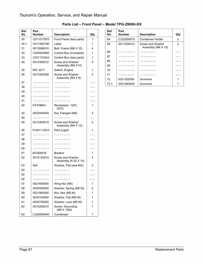
Ref. No.
Part Number
Description
Qty
30 C011017970 Front Panel (less parts) 1
30.1 C011900180 Label 1
31 0013006010 Bolt, Frame (M6 X 10) 4
32 C020004695 Control Box (Complete) 1
33 C021103243 Control Box (less parts) 1
34 0014305012 Screw and Washer Assembly (M5 X12)
4
35 SW -3211 Switch, Engine 1
36 0013303008 Screw and Washer Assembly (M3 X 8)
2
37 - - - - - - - - - - - - - - - - - - - - -
38 - - - - - - - - - - - - - - - - - - - - -
39 - - - - - - - - - - - - - - - - - - - - -
40 - - - - - - - - - - - - - - - - - - - - -
41 - - - - - - - - - - - - - - - - - - - - -
42 GF53BKA Receptacle, 120V, GFCI
1
43 0022004000 Nut, Flanged (M4) 2
44 - - - - - - - - - - - - - - - - - - - -
45 0013304010 Screw and Washer Assembly (M4 X 10)
2
46 01401110G0 Pilot (Light) 1
47 - - - - - - - - - - - - - - - - - - - - -
48 - - - - - - - - - - - - - - - - - - - - -
49 - - - - - - - - - - - - - - - - - - - - -
50 - - - - - - - - - - - - - - - - - - - - -
51 IEGBX618 Breaker 1
52 0015130510 Screw and Washer Assembly (6-32 X 10)
2
53 N/A Washer, Flat (see #52) 2
54 - - - - - - - - - - - - - - - - - - - - -
55 - - - - - - - - - - - - - - - - - - - - -
56 - - - - - - - - - - - - - - - - - - - - -
57 0021805000 Wing Nut (M5) 1
58 0030405000 Washer, Spring (M5 Ni) 2
59 0021905000 Nut, Hex (M5 Ni) 1
60 0030105000 Washer, Flat (M5 Ni) 1
61 0030705000 Washer, Lock (M5 Ni) 1
62 0010205015 Screw, Grounding (M5 X 15Ni)
1
63 C220000440 Condenser 1
Ref. No.
Part Number
Description
Qty
64 C222000010 Condenser Holder 2
65 0011204010 Screw and Washer Assembly (M4 X 10)
2
66 - - - - - - - - - - - - - - - - - - - - -
67 - - - - - - - - - - - - - - - - - - - - -
68 - - - - - - - - - - - - - - - - - - - - -
69 - - - - - - - - - - - - - - - - - - - - -
70 - - - - - - - - - - - - - - - - - - - - -
71 - - - - - - - - - - - - - - - - - - - - -
72 0321302509 Grommet 1
72.1 0321090509 Grommet 1
Parts List Front Panel Model TPG-2900H-DX
Page 67 Replacement Parts
Tsurumi’s Operation, Service, and Repair Manual
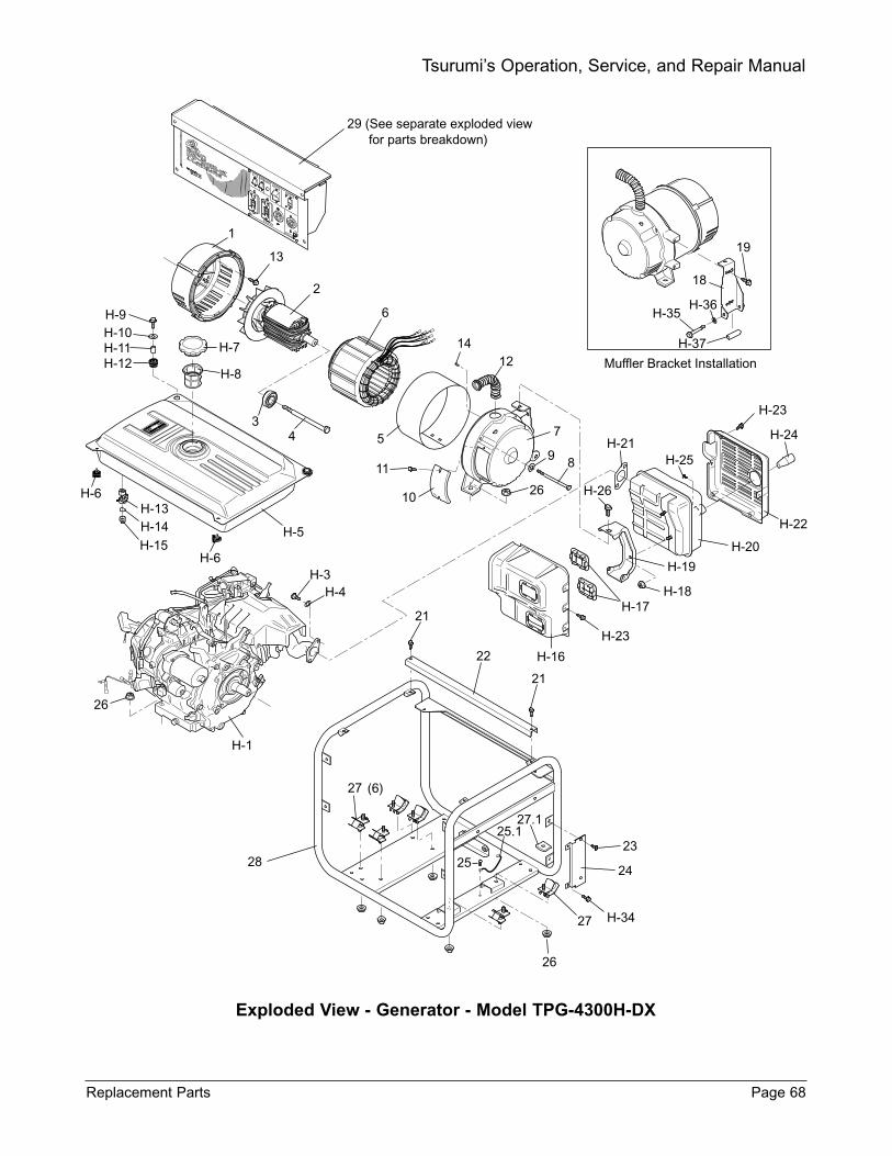
Exploded View - Generator - Model TPG-4300H-DX
Replacement Parts Page 68
Tsurumi’s Operation, Service, and Repair Manual
29 (See separate exploded view for parts breakdown)
1
13
2
6
1412 Muffler Bracket Installation
H-37
H-35H-36
18
19
H-9H-10H-11H-12
H-7
H-8
34
H-6H-13H-14
H-15H-6
H-5
5
11
10
7
9 8
26
H-3H-4
H-1
26
21
21
22
23
24
27
26
27
25
25.127.1
H-16
H-23
H-17H-18
H-19
H-20
H-21
H-22
H-23
H-24
H-25
H-26
28
H-34
(6)
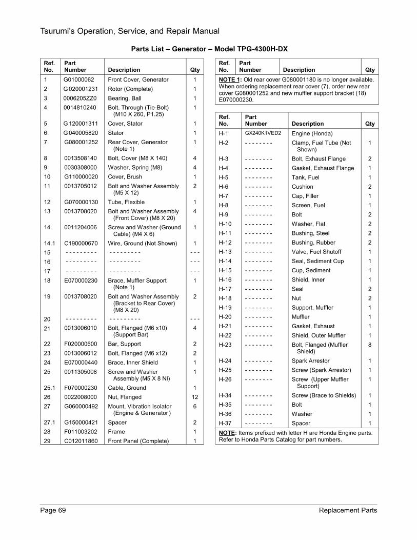
Ref. No.
Part Number
Description
Qty
1 G01000062 Front Cover, Generator 1
2 G 020001231 Rotor (Complete) 1
3 0006205ZZ0 Bearing, Ball 1
4 0014810240 Bolt, Through (Tie-Bolt) (M10 X 260, P1.25)
1
5 G 120001311 Cover, Stator 1
6 G 040005820 Stator 1
7 G080001252 Rear Cover, Generator (Note 1)
1
8 0013508140 Bolt, Cover (M8 X 140) 4
9 0030308000 Washer, Spring (M8) 4
10 G110000020 Cover, Brush 1
11 0013705012 Bolt and Washer Assembly (M5 X 12)
2
12 G070000130 Tube, Flexible 1
13 0013708020 Bolt and Washer Assembly (Front Cover) (M8 X 20)
4
14 0011204006 Screw and Washer (Ground Cable) (M4 X 6)
1
14.1 C190000670 Wire, Ground (Not Shown) 1
15 - - - - - - - - - - - - - - - - - - - - -
16 - - - - - - - - - - - - - - - - - - - - -
17 - - - - - - - - - - - - - - - - - - - - -
18 E070000230 Brace, Muffler Support (Note 1)
1
19 0013708020 Bolt and Washer Assembly (Bracket to Rear Cover) (M8 X 20)
2
20 - - - - - - - - - - - - - - - - - - - - -
21 0013006010 Bolt, Flanged (M6 x10) (Support Bar)
4
22 F020000600 Bar, Support 2
23 0013006012 Bolt, Flanged (M6 x12) 2
24 E070000440 Brace, Inner Shield 1
25 0011305008 Screw and Washer Assembly (M5 X 8 NI)
1
25.1 F070000230 Cable, Ground 1
26 0022008000 Nut, Flanged 12
27 G060000492 Mount, Vibration Isolator (Engine & Generator )
6
27.1 G150000421 Spacer 2
28 F011003202 Frame 1
29 C012011860 Front Panel (Complete) 1
Ref. No.
Part Number
Description
Qty
NOTE 1: Old rear cover G080001180 is no longer available. When ordering replacement rear cover (7), order new rear cover G080001252 and new muffler support bracket (18) E070000230.
Ref. No.
Part Number
Description
Qty
H-1 GX240K1VED2 Engine (Honda)
H-2 - - - - - - - - Clamp, Fuel Tube (Not Shown)
1
H-3 - - - - - - - - Bolt, Exhaust Flange 2
H-4 - - - - - - - - Gasket, Exhaust Flange 1
H-5 - - - - - - - - Tank, Fuel 1
H-6 - - - - - - - - Cushion 2
H-7 - - - - - - - - Cap, Filler 1
H-8 - - - - - - - - Screen, Fuel 1
H-9 - - - - - - - - Bolt 2
H-10 - - - - - - - - Washer, Flat 2
H-11 - - - - - - - - Bushing, Steel 2
H-12 - - - - - - - - Bushing, Rubber 2
H-13 - - - - - - - - Valve, Fuel Shutoff 1
H-14 - - - - - - - - Seal, Sediment Cup 1
H-15 - - - - - - - - Cup, Sediment 1
H-16 - - - - - - - - Shield, Inner 1
H-17 - - - - - - - - Seal 2
H-18 - - - - - - - - Nut 2
H-19 - - - - - - - - Support, Muffler 1
H-20 - - - - - - - - Muffler 1
H-21 - - - - - - - - Gasket, Exhaust 1
H-22 - - - - - - - - Shield, Outer Muffler 1
H-23 - - - - - - - - Bolt, Flanged (Muffler Shield)
8
H-24 - - - - - - - - Spark Arrestor 1
H-25 - - - - - - - - Screw (Spark Arrestor) 1
H-26 - - - - - - - - Screw (Upper Muffler Support)
1
H-34 - - - - - - - - Screw (Brace to Shields) 1
H-35 - - - - - - - - Bolt 1
H-36 - - - - - - - - Washer 1
H-37 - - - - - - - - Spacer 1
NOTE: Items prefixed with letter H are Honda Engine parts. Refer to Honda Parts Catalog for part numbers.
Parts List Generator Model TPG-4300H-DX
Page 69 Replacement Parts
Tsurumi’s Operation, Service, and Repair Manual
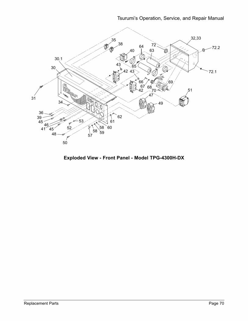
Exploded View - Front Panel - Model TPG-4300H-DX
Replacement Parts Page 70
Tsurumi’s Operation, Service, and Repair Manual
32,333538
40
43
646372
51
49
47
43
69
7068
65
6766
42
4230
30.1
3134
363945
4641 45 52
53
48
50
57
605858 59
6162
72.2
72.1
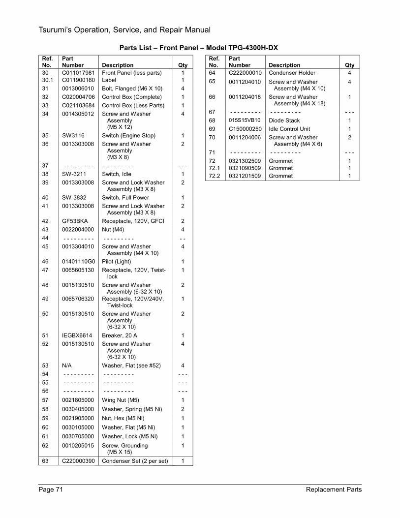
Ref. No.
Part Number
Description
Qty
30 C011017981 Front Panel (less parts) 1 30.1 C011900180 Label 1
31 0013006010 Bolt, Flanged (M6 X 10) 4
32 C020004706 Control Box (Complete) 1
33 C021103684 Control Box (Less Parts) 1
34 0014305012 Screw and Washer Assembly (M5 X 12)
4
35 SW3116 Switch (Engine Stop) 1
36 0013303008 Screw and Washer Assembly (M3 X 8)
2
37 - - - - - - - - - - - - - - - - - - - - -
38 SW-3211 Switch, Idle 1
39 0013303008 Screw and Lock Washer Assembly (M3 X 8)
2
40 SW-3832 Switch, Full Power 1
41 0013303008 Screw and Lock Washer Assembly (M3 X 8)
2
42 GF53BKA Receptacle, 120V, GFCI 2
43 0022004000 Nut (M4) 4
44 - - - - - - - - - - - - - - - - - - - - 45 0013304010 Screw and Washer
Assembly (M4 X 10) 4
46 01401110G0 Pilot (Light) 1
47 0065605130 Receptacle, 120V, Twist-lock
1
48 0015130510 Screw and Washer Assembly (6-32 X 10)
2
49 0065706320 Receptacle, 120V/240V, Twist-lock
1
50 0015130510 Screw and Washer Assembly (6-32 X 10)
2
51 IEGBX6614 Breaker, 20 A 1
52 0015130510 Screw and Washer Assembly (6-32 X 10)
4
53 N/A Washer, Flat (see #52) 4
54 - - - - - - - - - - - - - - - - - - - - -
55 - - - - - - - - - - - - - - - - - - - - -
56 - - - - - - - - - - - - - - - - - - - - -
57 0021805000 Wing Nut (M5) 1
58 0030405000 Washer, Spring (M5 Ni) 2
59 0021905000 Nut, Hex (M5 Ni) 1
60 0030105000 Washer, Flat (M5 Ni) 1
61 0030705000 Washer, Lock (M5 Ni) 1
62 0010205015 Screw, Grounding (M5 X 15)
1
63 C220000390 Condenser Set (2 per set) 1
Ref. No.
Part Number
Description
Qty
64 C222000010 Condenser Holder 4
65 0011204010 Screw and Washer Assembly (M4 X 10)
4
66 0011204018 Screw and Washer Assembly (M4 X 18)
1
67 - - - - - - - - - - - - - - - - - - - - -
68 015S15VB10 Diode Stack 1
69 C150000250 Idle Control Unit 1
70 0011204006 Screw and Washer Assembly (M4 X 6)
2
71 - - - - - - - - - - - - - - - - - - - - -
72 0321302509 Grommet 1 72.1 0321090509 Grommet 1 72.2 0321201509 Grommet 1
Parts List Front Panel Model TPG-4300H-DX
Page 71 Replacement Parts
Tsurumi’s Operation, Service, and Repair Manual
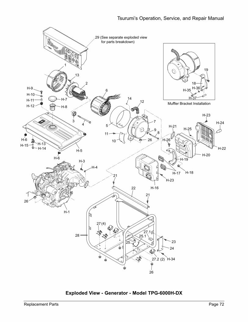
Exploded View - Generator - Model TPG-6000H-DX
Replacement Parts Page 72
Tsurumi’s Operation, Service, and Repair Manual
18
19
H-35H-36
H-37
29 (See separate exploded view for parts breakdown)
1
13
2
6
1412
5
11
10
7
98
26
Muffler Bracket Installation
H-23
H-24H-21
H-25
H-26
H-20H-19
H-18H-17
H-22
H-23
H-16
21
21
22
23
27.1
25
25.1
24
27.2
26
27
28
H-1
H-6H-13H-14
H-15
H-6
H-5
34
H-7
H-8
H-9
H-10
H-11
H-12
26
H-3
H-4
H-34
(4)
(2)

Ref. No.
Part Number
Description
Qty
1 G010000551 Front Cover, Generator 1
2 G020001241 Rotor (Complete) 1
3 Bearing, Ball 1
4 0014810260 Bolt, Through (Tie-Bolt) (M10 X 260, P1.25)
1
5 G120001331 Cover, Stator 1
6 G040005830 Stator 1
7 G080001262 Rear Cover, Generator (Note 1)
1
8 0013508160 Bolt, Cover (M8 X 160) 4
9 0030308000 Washer, Spring (M8) 4
10 G110000020 Cover, Brush 1
11 0013705012 Bolt and Washer Assembly (M5 X 12)
2
12 G070000130 Tube, Flexible 1
13 0013708020 Bolt and Washer Assembly (Front Cover) (M8 X 20)
4
14 0011204006 Screw and Washer (Ground Cable) (M4 X 6)
1
14.1 C190000670 Wire, Ground (Not Shown) 1
15 - - - - - - - - - - - - - - - - - - - - -
16 - - - - - - - - - - - - - - - - - - - - -
17 - - - - - - - - - - - - - - - - - - - - -
18 E070000230 Bracket, Muffler Support (Note 1)
1
19 0013708020 Bolt and Washer Assembly (Bracket to Rear Cover) (M8 X 20)
2
20 - - - - - - - - - - - - - - - - - - - - -
21 0013006010 Bolt, Flanged (M6 x10) (Support Bar)
4
22 F020000610 Bar, Support 2
23 0013006012 Bolt, Flanged (M6 x12) 2
24 E070000052 Brace, Inner Shield 1
25 0011305008 Screw and Washer Assembly (M5 X 8 NI)
1
25.1 F070000230 Cable, Ground 1
26 0022008000 Nut, Flanged 12
27 G060000492 Mount, Vibration Isolator (Engine)
4
27.1 G150000421 Spacer 2
27.2 G060000482 Mount, Vibration Isolator (Generator)
2
Ref. No.
Part Number
Description
Qty
H-1 GX340K1ED6 Engine (Honda)
H-2 - - - - - - - - Clamp, Fuel Tube (Not Shown)
1
H-3 - - - - - - - - Bolt, Exhaust Flange 2
H-4 - - - - - - - - Gasket, Exhaust Flange 1
H-5 - - - - - - - - Tank, Fuel 1
H-6 - - - - - - - - Cushion 2
H-7 - - - - - - - - Cap, Filler 1
H-8 - - - - - - - - Screen, Fuel 1
H-9 - - - - - - - - Bolt 2
H-10 - - - - - - - - Washer, Flat 2
H-11 - - - - - - - - Bushing, Steel 2
H-12 - - - - - - - - Bushing, Rubber 2
H-13 - - - - - - - - Valve, Fuel Shutoff 1
H-14 - - - - - - - - Seal, Sediment Cup 1
H-15 - - - - - - - - Cup, Sediment 1
H-16 - - - - - - - - Shield, Inner 1
H-17 - - - - - - - - Seal 2
H-18 - - - - - - - - Nut 2
H-19 - - - - - - - - Support, Muffler 1
H-20 - - - - - - - - Muffler 1
H-21 - - - - - - - - Gasket, Exhaust 1
H-22 - - - - - - - - Shield, Outer Muffler 1
H-23 - - - - - - - - Bolt, Flanged (Muffler Shield) 8
H-24 - - - - - - - - Spark Arrestor 1
H-25 - - - - - - - - Screw (Spark Arrestor) 1
H-26 - - - - - - - - Screw (Upper Muffler Support)
1
H-34 - - - - - - - - Screw (Brace to Shields) 1
H-35 - - - - - - - - Bolt 1
H-36 - - - - - - - - Washer 1
H-37 - - - - - - - - Spacer 1
NOTE: Items prefixed with letter H are Honda Engine parts. Refer to Honda Parts Catalog for part numbers.
Parts List Generator Model TPG-6000H-DX
0006205ZZ0
Page 73 Replacement Parts
Tsurumi’s Operation, Service, and Repair Manual
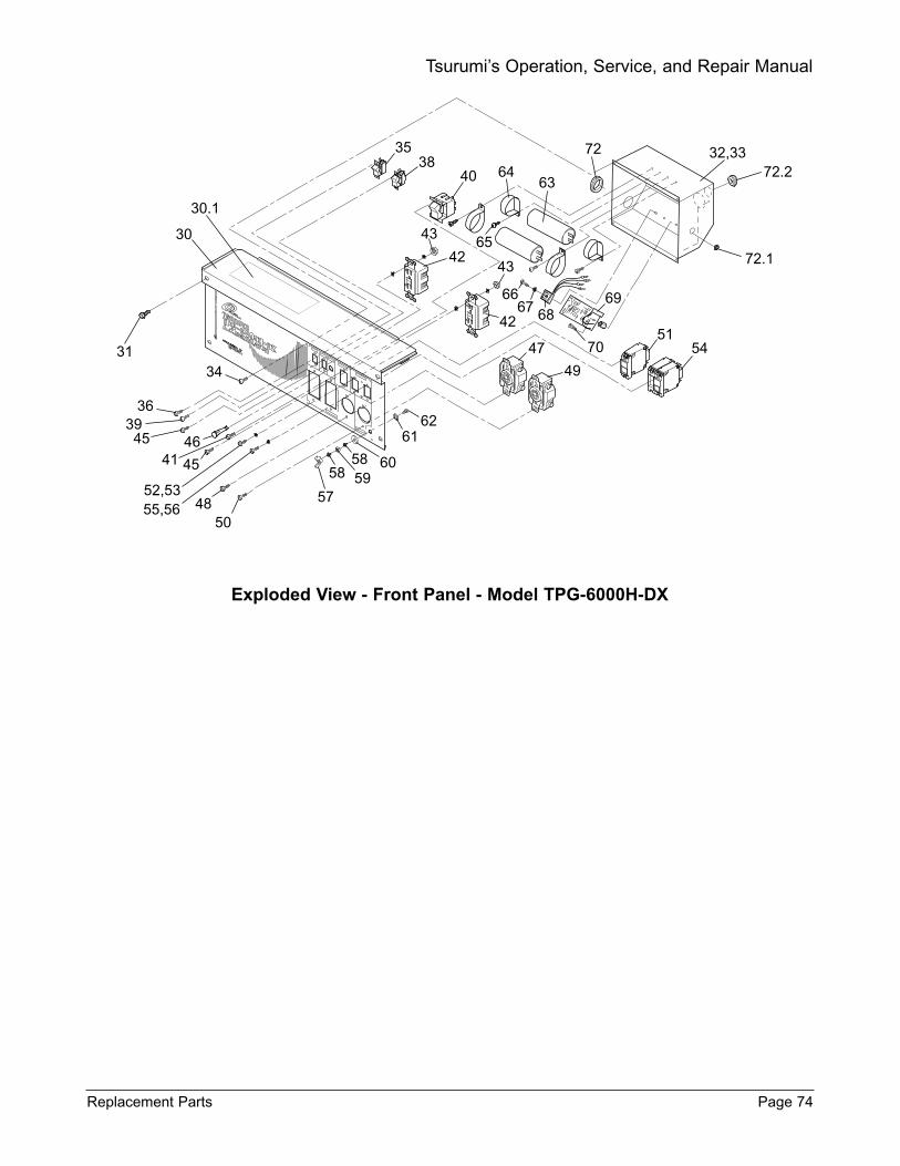
Exploded View - Front Panel - Model TPG-6000H-DX
Replacement Parts Page 74
Tsurumi’s Operation, Service, and Repair Manual
30.1
30
31
363945 46
41 45
52,5355,56 48
50
34
57595858 60
6162
3538
40
43
4243
42
47
49
32,33
6667 68
515470
69
6463
72
6572.1
72.2
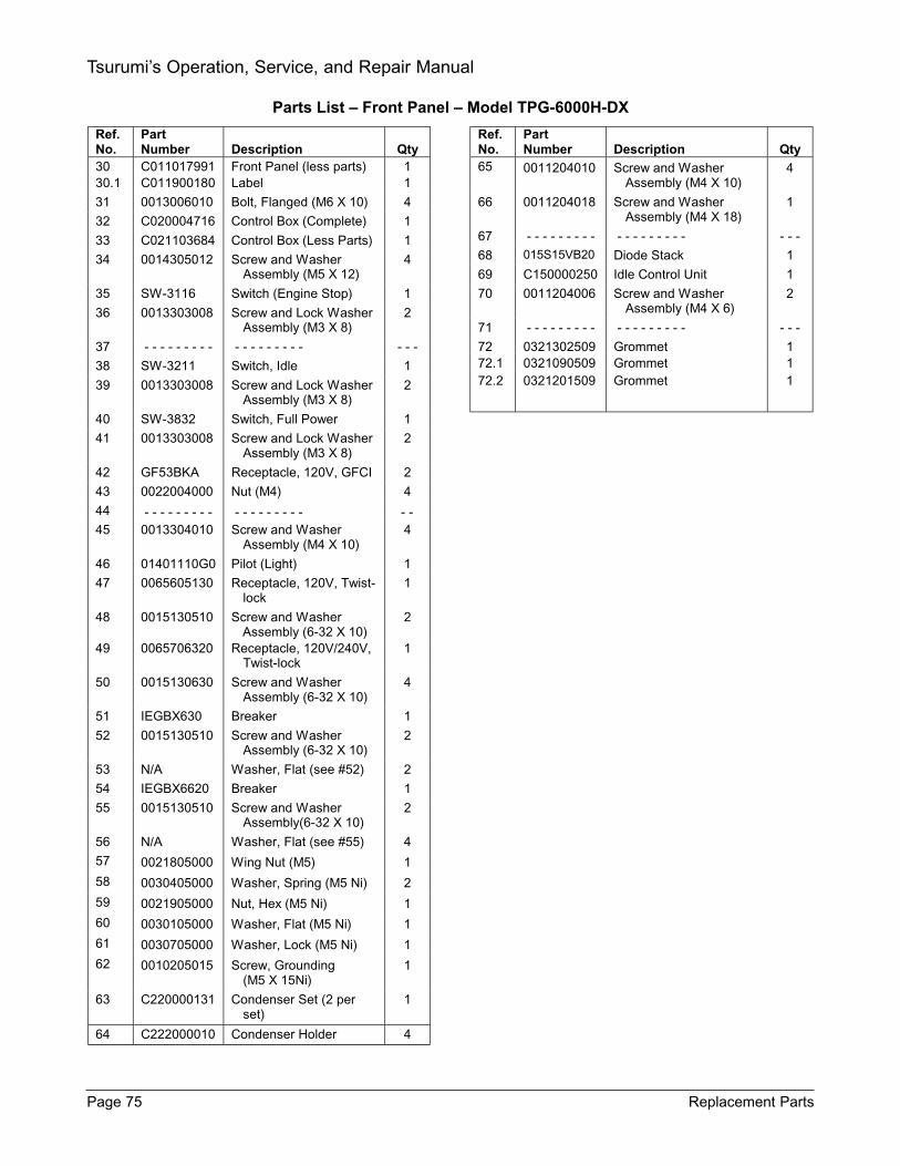
Parts List Front Panel Model TPG-6000H-DX
Ref. No.
Part Number
Description
Qty
30 C011017991 Front Panel (less parts) 1 30.1 C011900180 Label 1
31 0013006010 Bolt, Flanged (M6 X 10) 4
32 C020004716 Control Box (Complete) 1
33 C021103684 Control Box (Less Parts) 1
34 0014305012 Screw and Washer Assembly (M5 X 12)
4
35 SW-3116 Switch (Engine Stop) 1
36 0013303008 Screw and Lock Washer Assembly (M3 X 8)
2
37 - - - - - - - - - - - - - - - - - - - - -
38 SW-3211 Switch, Idle 1
39 0013303008 Screw and Lock Washer Assembly (M3 X 8)
2
40 SW-3832 Switch, Full Power 1
41 0013303008 Screw and Lock Washer Assembly (M3 X 8)
2
42 GF53BKA Receptacle, 120V, GFCI 2
43 0022004000 Nut (M4) 4
44 - - - - - - - - - - - - - - - - - - - - 45 0013304010 Screw and Washer
Assembly (M4 X 10) 4
46 01401110G0 Pilot (Light) 1
47 0065605130 Receptacle, 120V, Twist-lock
1
48 0015130510 Screw and Washer Assembly (6-32 X 10)
2
49 0065706320 Receptacle, 120V/240V, Twist-lock
1
50 0015130630 Screw and Washer Assembly (6-32 X 10)
4
51 IEGBX630 Breaker 1
52 0015130510 Screw and Washer Assembly (6-32 X 10)
2
53 N/A Washer, Flat (see #52) 2
54 IEGBX6620 Breaker 1
55 0015130510 Screw and Washer Assembly(6-32 X 10)
2
56 N/A Washer, Flat (see #55) 4
57 0021805000 Wing Nut (M5) 1
58 0030405000 Washer, Spring (M5 Ni) 2
59 0021905000 Nut, Hex (M5 Ni) 1
60 0030105000 Washer, Flat (M5 Ni) 1
61 0030705000 Washer, Lock (M5 Ni) 1
62 0010205015 Screw, Grounding (M5 X 15Ni)
1
63 C220000131 Condenser Set (2 per set)
1
64 C222000010 Condenser Holder 4
Ref. No.
Part Number
Description
Qty
65 0011204010 Screw and Washer Assembly (M4 X 10)
4
66 0011204018 Screw and Washer Assembly (M4 X 18)
1
67 - - - - - - - - - - - - - - - - - - - - -
68 015S15VB20 Diode Stack 1
69 C150000250 Idle Control Unit 1
70 0011204006 Screw and Washer Assembly (M4 X 6)
2
71 - - - - - - - - - - - - - - - - - - - - -
72 0321302509 Grommet 1 72.1 0321090509 Grommet 1 72.2 0321201509 Grommet 1
Page 75 Replacement Parts
Tsurumi’s Operation, Service, and Repair Manual

Exploded View - Generator - Model TPG-7000H-DXE
Replacement Parts Page 76
Tsurumi’s Operation, Service, and Repair Manual
29 (See separate exploded view for parts breakdown)
H-37H-35
H-3618
1
213
6
514
12
11
4
3
H-7
H-8
H-9H-10H-11H-12
H-6
10 26
9
8
H-6
H-13H-14H-15
H-5
H-3
H-4
H-1
26
See separate view for battery enclosure parts
22
21
24
2325
25.1
27 (4)
28
26
H-16H-17 H-18
H-19H-20
H-23
H-21H-25
H-23
H-24
H-22
Muffler Bracket Installation
H-26
27.1
19
7
21
H-3427.2 (2)

Ref. No.
Part Number
Description
Qty
1 G010000551 Front Cover, Generator 1
2 G020001591 Rotor (Complete) 1
3 Bearing, Ball 1
4 0014810270 Bolt, Through (Tie-Bolt) (M10 X 270, P1.25)
1
5 G120001341 Cover, Stator 1
6 G040006380 Stator 1
7 G080001262 Rear Cover, Generator (Note 1)
1
8 0013508170 Bolt, Cover (M8 X 160) 4
9 0030308000 Washer, Spring (M8) 4
10 G110000020 Cover, Brush 1
11 0013705012 Bolt and Washer Assembly (M5 X 12)
2
12 G070000130 Tube, Flexible 1
13 0013708020 Bolt and Washer Assembly (Front Cover) (M8 X 20)
4
14 0011204006 Screw and Washer (Ground Cable) (M4 X 6)
1
14.1 C190000670 Wire, Ground (Not Shown) 1
15 Bolt (Lower Muffler Support) 1
16 Washer 1
17 Spacer, Tubular 1
18 E070000230 Bracket, Muffler Support (Note 1)
1
19 0013708020 Bolt and Washer Assembly (M8 X 20)
1
20 - - - - - - - - - - - - - - - - - - - - -
21 0013006012 Bolt, Flanged (M6 x10) (Support Bar)
4
22 F020000600 Bar, Support 2
23 0013006010 Bolt, Flanged (M6 x12) 2
24 E070000052 Brace, Inner Shield 1
25 0011305008 Screw and Washer Assembly (M5 X 10 NI)
1
25.1 F070000230 Cable, Ground 1
26 0022008000 Nut, Flanged 12
27 G060000492 Mount, Vibration Isolator (Engine)
4
27.1 G150000421 Spacer 2
27.2 G060000482 Mount, Vibration Isolator (Generator)
2
Ref. No.
Part Number
Description
Qty
28 F011003215 Frame 1
29 C012011890 Front Panel (Complete) 1
NOTE: Old rear cover G080001190 is no longer available. When ordering replacement rear cover (7), order new rear cover G080001262 and new muffler support bracket (18) E070000230.
Ref. No.
Part Number
Description
Qty
H-1 GX390K1EDD2 Engine (Honda)
H-2 - - - - - - - - Clamp, Fuel Tube (Not Shown)
1
H-3 - - - - - - - - Bolt, Exhaust Flange 2
H-4 - - - - - - - - Gasket, Exhaust Flange 1
H-5 - - - - - - - - Tank, Fuel 1
H-6 - - - - - - - - Cushion 2
H-7 - - - - - - - - Cap, Filler 1
H-8 - - - - - - - - Screen, Fuel 1
H-9 - - - - - - - - Bolt 2
H-10 - - - - - - - - Washer, Flat 2
H-11 - - - - - - - - Bushing, Steel 2
H-12 - - - - - - - - Bushing, Rubber 2
H-13 - - - - - - - - Valve, Fuel Shutoff 1
H-14 - - - - - - - - Seal, Sediment Cup 1
H-15 - - - - - - - - Cup, Sediment 1
H-16 - - - - - - - - Shield, Inner 1
H-17 - - - - - - - - Seal 2
H-18 - - - - - - - - Nut 2
H-19 - - - - - - - - Support, Muffler 1
H-20 - - - - - - - - Muffler 1
H-21 - - - - - - - - Gasket, Exhaust 1
H-22 - - - - - - - - Shield, Outer Muffler 1
H-23 - - - - - - - - Bolt, Flanged (Muffler Shield) 8
H-24 - - - - - - - - Spark Arrestor 1
H-25 - - - - - - - - Screw (Spark Arrestor) 1
H-26 - - - - - - - - Screw (Upper Muffler Support)
1
H-34 - - - - - - - - Screw (Brace to Shields) 1
H-35 - - - - - - - - Bolt 1
H-36 - - - - - - - - Washer 1
H-37 - - - - - - - - Spacer 1
NOTE: Items prefixed with letter H are Honda Engine parts. Refer to Honda Parts Catalog for part numbers.
Parts List Generator Model TPG-7000H-DXE
0006205ZZ0
Page 77 Replacement Parts
Tsurumi’s Operation, Service, and Repair Manual
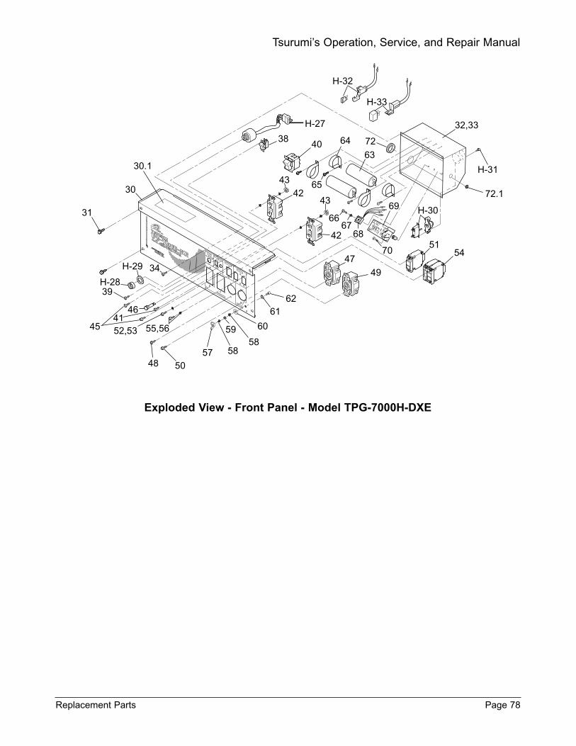
Exploded View - Front Panel - Model TPG-7000H-DXE
Replacement Parts Page 78
Tsurumi’s Operation, Service, and Repair Manual
H-32
H-33
72
32,33
H-31
H-27
3840
42
42
64
65
63
43
43
6667
68
69
70
H-30
5154
47
49
5758
59 60
6162
58
30
30.1
31
34
H-28
H-29
39
45
464152,53 55,56
48 50
72.1
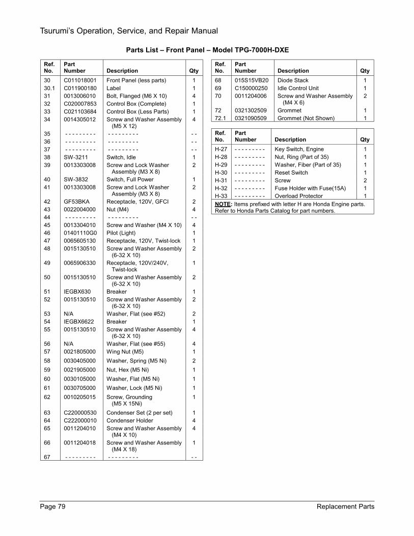
Ref. No.
Part Number
Description
Qty
30 C011018001 Front Panel (less parts) 1 30.1 C011900180 Label 1 31 0013006010 Bolt, Flanged (M6 X 10) 4 32 C020007853 Control Box (Complete) 1 33 C021103684 Control Box (Less Parts) 1 34 0014305012 Screw and Washer Assembly
(M5 X 12) 4
35 - - - - - - - - - - - - - - - - - - - - 36 - - - - - - - - - - - - - - - - - - - - 37 - - - - - - - - - - - - - - - - - - - - 38 SW-3211 Switch, Idle 1 39 0013303008 Screw and Lock Washer
Assembly (M3 X 8) 2
40 SW-3832 Switch, Full Power 1 41 0013303008 Screw and Lock Washer
Assembly (M3 X 8) 2
42 GF53BKA Receptacle, 120V, GFCI 2 43 0022004000 Nut (M4) 4 44 - - - - - - - - - - - - - - - - - - - - 45 0013304010 Screw and Washer (M4 X 10) 4 46 01401110G0 Pilot (Light) 1 47 0065605130 Receptacle, 120V, Twist-lock 1 48 0015130510 Screw and Washer Assembly
(6-32 X 10) 2
49 0065906330 Receptacle, 120V/240V, Twist-lock
1
50 0015130510 Screw and Washer Assembly (6-32 X 10)
2
51 IEGBX630 Breaker 1 52 0015130510 Screw and Washer Assembly
(6-32 X 10) 2
53 N/A Washer, Flat (see #52) 2 54 IEGBX6622 Breaker 1 55 0015130510 Screw and Washer Assembly
(6-32 X 10) 4
56 N/A Washer, Flat (see #55) 4 57 0021805000 Wing Nut (M5) 1
58 0030405000 Washer, Spring (M5 Ni) 2
59 0021905000 Nut, Hex (M5 Ni) 1
60 0030105000 Washer, Flat (M5 Ni) 1
61 0030705000 Washer, Lock (M5 Ni) 1
62 0010205015 Screw, Grounding (M5 X 15Ni)
1
63 C220000530 Condenser Set (2 per set) 1 64 C222000010 Condenser Holder 4 65 0011204010 Screw and Washer Assembly
(M4 X 10) 4
66 0011204018 Screw and Washer Assembly (M4 X 18)
1
67 - - - - - - - - - - - - - - - - - - - -
Ref. No.
Part Number
Description
Qty
68 015S15VB20 Diode Stack 1 69 C150000250 Idle Control Unit 1 70 0011204006 Screw and Washer Assembly
(M4 X 6) 2
72 0321302509 Grommet 1 72.1 0321090509 Grommet (Not Shown) 1 Ref. No.
Part Number
Description
Qty
H-27 - - - - - - - - - Key Switch, Engine 1 H-28 - - - - - - - - - Nut, Ring (Part of 35) 1 H-29 - - - - - - - - - Washer, Fiber (Part of 35) 1 H-30 - - - - - - - - - Reset Switch 1 H-31 - - - - - - - - - Screw 2 H-32 - - - - - - - - - Fuse Holder with Fuse(15A) 1 H-33 - - - - - - - - - Overload Protector 1
NOTE: Items prefixed with letter H are Honda Engine parts. Refer to Honda Parts Catalog for part numbers.
Parts List Front Panel Model TPG-7000H-DXE
Page 79 Replacement Parts
Tsurumi’s Operation, Service, and Repair Manual

Replacement Parts Page 80
Tsurumi’s Operation, Service, and Repair Manual
Parts List - Battery Enclosure - Model TPG-7000H-DXE
Ref.No.
PartNumber Description Qty
- - - FU11003215 Pipe Frame Unit ( Electric 1(Complete) (Not Shown)
73 F200000260 Tube, Battery Support 274 F080000300 Base Plate, Battery 175 F241000050 Plate, Battery Shield 176 F090000130 Plate, Battery Hold-down 177 F100000011 Rod, Tie Down (M6 X 200) 278 F091000031 Clip 279 0021506000 Wing Nut (Tie Down) (M6) 280 0013708020 Bolt and Washer Assembly
(Tube-to-Frame) (M8 x 20L) 481 0022008000 Nut, Self-locking (M8) 482 0013706040 Bolt and Washer Assembly
(Base Plate-to-Tube) (M6 X 40L) 4
83 0022006000 Nut, Self-locking (M6) 484 0013706040 Screw and Washer Assembly
(Shield to Tube) (M6 X 40L) 485 0022006000 Nut, Self-locking (M6) 486 B040000451 Cord, Battery (Not Shown) 2
NOTE: Components listed above are available in Kit BTKTPG7000.
Parts List Battery Enclosure Model TPG-7000H-DXE
79
78
82
77
74
80
81
83
73
75
8485
76

APPENDIX A
BATTERY ENCLOSURE KITASSEMBLY AND INSTALLATION
INSTRUCTIONS
FORTSURUMI MODEL TPG-7000H-DXE
PORTABLE GENERATOR
Page A-1 Appendix A
Tsurumi’s Operation, Service, and Repair Manual
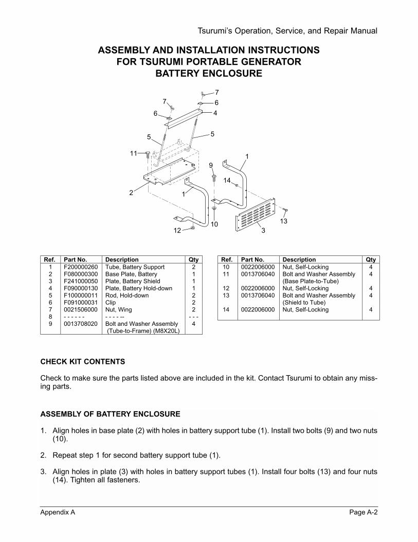
ASSEMBLY AND INSTALLATION INSTRUCTIONSFOR TSURUMI PORTABLE GENERATOR
BATTERY ENCLOSURE
CHECK KIT CONTENTS
Check to make sure the parts listed above are included in the kit. Contact Tsurumi to obtain any miss-ing parts.
Appendix A Page A-2
Tsurumi’s Operation, Service, and Repair Manual
7
6
7
6
4
55
11
2 1
1210
313
14
19
ASSEMBLY OF BATTERY ENCLOSURE
1. Align holes in base plate (2) with holes in battery support tube (1). Install two bolts (9) and two nuts(10).
2. Repeat step 1 for second battery support tube (1).
3. Align holes in plate (3) with holes in battery support tubes (1). Install four bolts (13) and four nuts(14). Tighten all fasteners.
Ref. Part No. Description Qty1 F200000260 Tube, Battery Support 22 F080000300 Base Plate, Battery 13 F241000050 Plate, Battery Shield 14 F090000130 Plate, Battery Hold-down 15 F100000011 Rod, Hold-down 26 F091000031 Clip 27 0021506000 Nut, Wing 28 - - - - - - - - - - -- - - -9 0013708020 Bolt and Washer Assembly
(Tube-to-Frame) (M8X20L)4
Ref. Part No. Description Qty10 0022006000 Nut, Self-Locking 411 0013706040 Bolt and Washer Assembly
(Base Plate-to-Tube)4
12 0022006000 Nut, Self-Locking 413 0013706040 Bolt and Washer Assembly
(Shield to Tube)4
14 0022006000 Nut, Self-Locking 4

INSTALLATION OF BATTERY ENCLOSURE
1. Position assembled enclosure on crossover support on bottom of generator frame. Install two bolts(11) through support tubes (1) and generator frame. Install and tighten nuts (12).
2. Align holes in support tubes (1) with holes in upper frame. Install two bolts (13) and nuts (14).
3. Check to make sure all bolts and nuts are tight.
Page A-3 Appendix A
Tsurumi’s Operation, Service, and Repair Manual
INSTALLATION OF BATTERY
1. Set battery on base plate (2). Place hold-down plate (4) on front edge of battery.
2. Install hooked end of tie-down rods (5) in holes in base plate (2). Put threaded ends of tie-downrods (5) up through holes in hold-down plate (4).
3. Install raised edge clips (6) toward terminals. Install wing nuts (7) on tie down rods. Tighten wingnuts (7).
4. Connect battery cables to terminals.
5. Start the generator to verify that the battery is properly connected.
CLIP, SPRINGWASHER, ANDWING NUT
HOLD-DOWNPLATE (4)
BASEPLATE (2)
TIE-DOWN ROD

APPENDIX B
PGWK-100 WHEEL KIT INSTALLATION INSTRUCTIONS
Appendix B Page B-1
Tsurumi’s Operation, Service, and Repair Manual

WHEEL KIT INSTALLATION INSTRUCTIONSFOR TSURUMI GENERATORS AND PUMPS
KIT CONTENTS
Check to make sure the following parts are included the kit. Contact Tsurumi to obtain any missingparts.
DRAIN FLUIDS
Drain oil from engine and drain fuel from fuel tank to avoid spillage during installation of the wheel kit(refer to Tsurumi Operation, Service, and Repair Manual for draining instructions).
Page B-2 Appendix B
Tsurumi’s Operation, Service, and Repair Manual
11
3
1
16
23
3
3
4
4
6
5
5
5
514
14
15
157
7
8
8
9
9
10
12
13
10
PUMP AXLEARRANGEMENT
GENERATOR AXLEARRANGEMENT
DRILL 3/8-INCHHOLES HERE INPUMP FRAME
DRILL 3/8-INCHHOLES HERE INGENERATORFRAME
View A
Ref. Part No. Description Qty1 PGWK-1 Handle, Left 12 PGWK-2 Handle, Right 13 PGWK-3 Clamp, Handle 44 PGWK-4 Plate, Handle Clamp 45 PGWK-5 Screw 86 PGWK-6 Nut 87 PGWK-7 Axle 18 PGWK-8 Clamp, Axle 2
Ref. Part No. Description Qty9 PGWK-9 Screw 4
10 PGWK-10 Nut 411 PGWK-11 U-Bolt 212 PGWK-12 Plate, U-Bolt 213 PGWK-13 Nut 414 PGWK-14 Wheel 215 PGWK-15 Cap, Axle 216 PGWK-16 Grip, Handle 2

INSTALL AXLE ON GENERATOR
1. Position portable generator frame on end (engine downward and generator upward).
2. Place a clamp (8) on the frame cross-member. Use clamp (8) as a template and mark center ofthe holes in clamp (8) with a center punch.
3. Use the center punch dimple as a guide and drill two 3/8-inch holes through the frame cross-mem-ber as shown in View A.
4. Repeat step 2 and 3 for the second set of axle clamp holes.
5. Place axle (7) on frame cross-member. Install two axle clamps (8) over axle (7) and secure withscrews (5) and nuts (6). Before tightening screws, make sure axle extends an equal amount fromthe sides of the generator frame. Tighten nuts (6).
INSTALL AXLE ON TRASH PUMP
1. Position pump frame on end (engine downward and pump upward).
2. Position a U-bolt plate (12) to the frame cross-member. Use plate (12) as a template and mark cen-ter of the holes with center punch.
3. Use the center punch dimple as a guide and drill two 3/8-inch holes through the frame cross-mem-ber as shown in View A.
4. Repeat steps 2 and 3 for the second set of U-bolt holes.
5. Place axle (7) on frame cross-member. Install U-bolts (11) over the axle (7). Put plate (12) overthreaded ends of U-bolts (11) and install nuts (13). Before tightening nuts, make sure axle extendsan equal amount from the sides of the pump frame. Tighten nuts (13).
INSTALL WHEELS
1. Position hub side of wheel toward frame and slide wheel (14) onto axle (7). Install cap (15) overend of axle (7) and drive onto axle using a hammer.
2. Repeat step 1 for the second wheel (14).
INSTALL HANDLES
1. Position frame upright on wheels. Place frame into channel at lower end of the left handle (1).Position the left handle (1) against the vertical tube of the frame.
2. Hold one clamp (3) on the outside of the frame and one plate (4) on the inside of the frame. Alignholes in clamp and plate and install screws (5). Install nuts but do not tighten.
3. If wheel kit is being installed on a pump, repeat steps 1 and 2 for right handle (2), then proceed tostep 9.
4. If you are installing the kit on a portable generator, complete steps 5 through 8. (A 5/16-inch holemust be drilled through the generator’s front panel to enable installation of one of the handle clampscrews.)
5. Hold a handle clamp (3) against the generator’s right handle and front panel. Use a center punchand mark the location of the hole in clamp (3) on the front panel.
6. Use the center punch dimple as a guide and drill a 5/16-inch hole through the front panel (see View B).
7. Position clamp (3) over the frame and overthe hole in the front panel. Align holes inclamp (3) and plate (4) and install screws(5) and nuts (6).
8. Tighten screws (5) and nuts (6). Install han-dle grips (16) on handles.
Appendix B Page B-3
Tsurumi’s Operation, Service, and Repair Manual
View B
Drill one 5/16-inch hole herefor attaching handle clamp

APPENDIX C
PGWK-200 WHEEL KIT INSTALLATION INSTRUCTIONS
Page C-1 Appendix C
Tsurumi’s Operation, Service, and Repair Manual
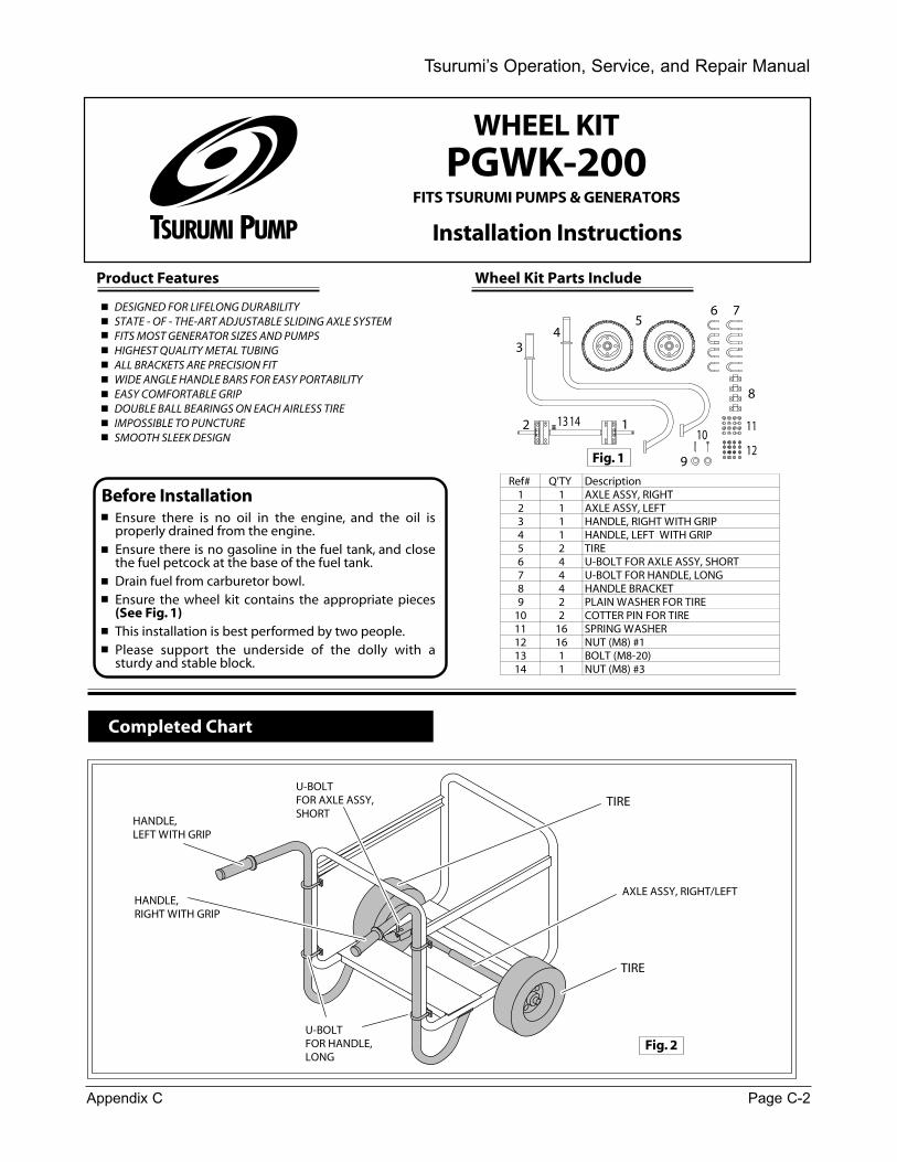
Tsurumi’s Operation, Service, and Repair Manual
Completed Chart
Before Installation
TIRE
TIRE
AXLE ASSY, RIGHT/LEFTHANDLE,RIGHT WITH GRIP
HANDLE,LEFT WITH GRIP
U-BOLTFOR HANDLE,LONG
U-BOLTFOR AXLE ASSY,SHORT
Wheel Kit Parts Include
Ref# Q'TY Description1 1 AXLE ASSY, RIGHT2 1 AXLE ASSY, LEFT3 1 HANDLE, RIGHT WITH GRIP4 1 HANDLE, LEFT WITH GRIP5 2 TIRE6 4 U-BOLT FOR AXLE ASSY, SHORT7 4 U-BOLT FOR HANDLE, LONG8 4 HANDLE BRACKET9 2 PLAIN WASHER FOR TIRE
10 2 COTTER PIN FOR TIRE11 16 SPRING WASHER12 16 NUT (M8) #113 1 BOLT (M8-20) 14 1 NUT (M8) #3
12
34
56 7
8
9
1011
12
13 14
Ensure there is no oil in the engine, and the oil is properly drained from the engine.Ensure there is no gasoline in the fuel tank, and close the fuel petcock at the base of the fuel tank. Drain fuel from carburetor bowl.Ensure the wheel kit contains the appropriate pieces (See Fig. 1)This installation is best performed by two people.Please support the underside of the dolly with a sturdy and stable block.
DESIGNED FOR LIFELONG DURABILITYSTATE - OF - THE-ART ADJUSTABLE SLIDING AXLE SYSTEMFITS MOST GENERATOR SIZES AND PUMPSHIGHEST QUALITY METAL TUBINGALL BRACKETS ARE PRECISION FITWIDE ANGLE HANDLE BARS FOR EASY PORTABILITYEASY COMFORTABLE GRIPDOUBLE BALL BEARINGS ON EACH AIRLESS TIREIMPOSSIBLE TO PUNCTURESMOOTH SLEEK DESIGN
Product Features
Fig. 1
Fig. 2
WHEEL KITPGWK-200
FITS TSURUMI PUMPS & GENERATORS
Installation Instructions
Appendix C Page C-2
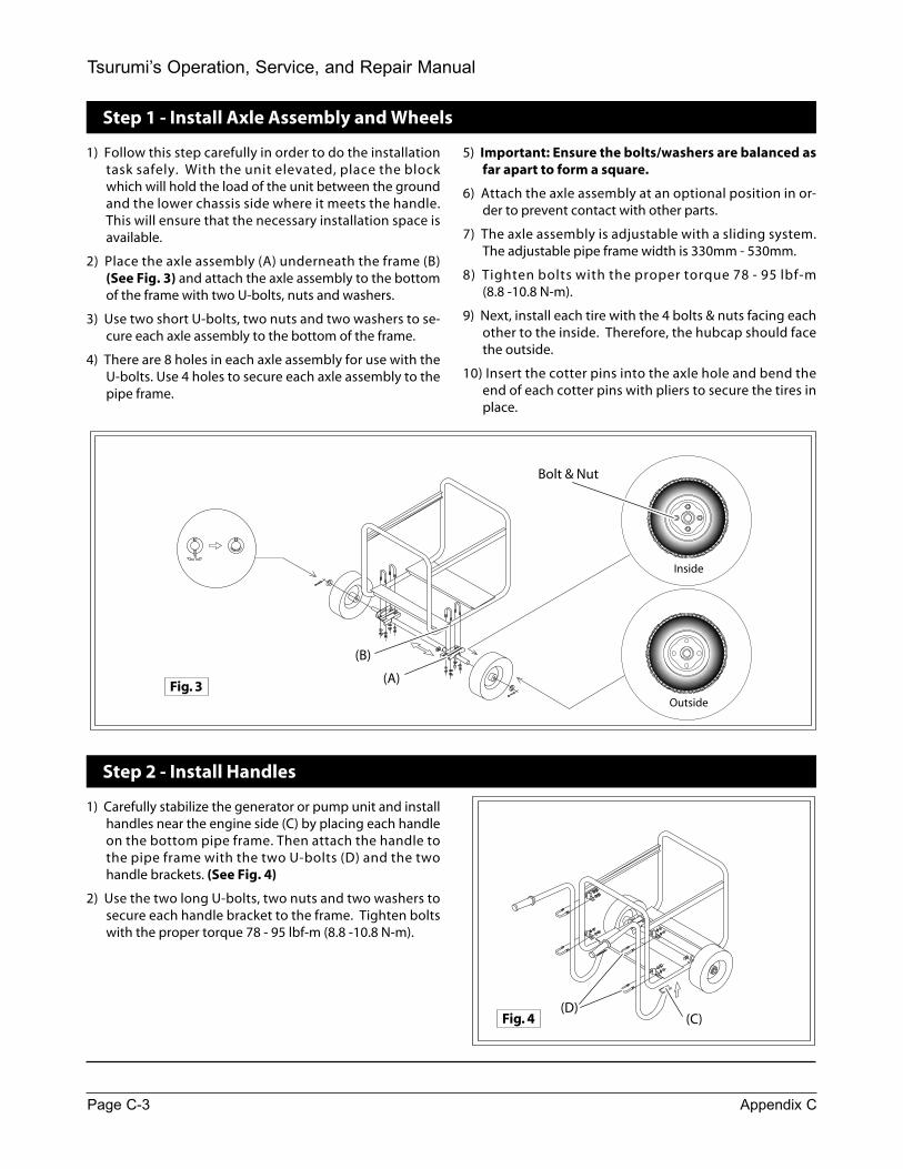
Page C-3 Appendix C
Tsurumi’s Operation, Service, and Repair Manual
Step 1 - Install Axle Assembly and Wheels
1) Follow this step carefully in order to do the installation task safely. With the unit elevated, place the block which will hold the load of the unit between the ground and the lower chassis side where it meets the handle. This will ensure that the necessary installation space is available.
2) Place the axle assembly (A) underneath the frame (B) (See Fig. 3) and attach the axle assembly to the bottom of the frame with two U-bolts, nuts and washers.
3) Use two short U-bolts, two nuts and two washers to se-cure each axle assembly to the bottom of the frame.
4) There are 8 holes in each axle assembly for use with the U-bolts. Use 4 holes to secure each axle assembly to the pipe frame.
Step 2 - Install Handles
1) Carefully stabilize the generator or pump unit and install handles near the engine side (C) by placing each handle on the bottom pipe frame. Then attach the handle to the pipe frame with the two U-bolts (D) and the two handle brackets. (See Fig. 4)
2) Use the two long U-bolts, two nuts and two washers to secure each handle bracket to the frame. Tighten bolts with the proper torque 78 - 95 lbf-m (8.8 -10.8 N-m).
5) Important: Ensure the bolts/washers are balanced as far apart to form a square.
6) Attach the axle assembly at an optional position in or-der to prevent contact with other parts.
7) The axle assembly is adjustable with a sliding system. The adjustable pipe frame width is 330mm - 530mm.
8) Tighten bolts with the proper torque 78 - 95 lbf-m (8.8 -10.8 N-m).
9) Next, install each tire with the 4 bolts & nuts facing each other to the inside. Therefore, the hubcap should face the outside.
10) Insert the cotter pins into the axle hole and bend the end of each cotter pins with pliers to secure the tires in place.
Inside
Outside
(A)
(B)
(C)(D)
Bolt & Nut
Fig. 3
Fig. 4