operation schemes of touch screen controllers
TRANSCRIPT
Application ReportSLAA359–May 2007
Operation Schemes of Touch Screen ControllersWendy Fang .................................................................................................. PAM - DAP Nyquist ADC
ABSTRACTThis application report describes the two operation schemes of touch-screen controller(TSC) devices, command-based and register-based, to help designers to select anduse the TSC devices best for their systems or applications. Under the differentschemes, the typical TSC operation steps are listed, the analog and digital interfacesare probed, and the system performances, including power consumption, are analyzed.
Contents1 Introduction .......................................................................................... 22 TSC System ......................................................................................... 33 Command-Based Scheme ........................................................................ 44 Advanced Command-Based Scheme............................................................ 85 Register-Based Scheme ......................................................................... 116 Register-Based Scheme With Batch-Delay.................................................... 137 Conclusion ......................................................................................... 158 References......................................................................................... 159 Glossary ............................................................................................ 16
List of Figures
1 Block Diagram of a 4-Wire Touch Screen System Using TI's TSC Device ................. 32 TSC2003 Analog Interface (Acquiring X, Y, Z1, Z2) ............................................ 53 TSC2003 Digital Interface (Host reads X Data, then Y, etc.) ................................. 54 Operating Sequence of Normal Command-Based TSC (for 2 touch data, X and Y) ...... 65 TSC2007 Analog Interface (Acquiring X, Y, Z1 and Z2) ....................................... 96 TSC2007 Digital Interface (Host reads X Data, then Y, etc.) ................................. 97 Operating Sequence of Advanced Command-Based TSC with Built-In 7-Data-Set
MAVF ............................................................................................... 108 TSC2004 Analog Interface Without Batch-Delay ............................................. 129 TSC2004 Digital Interface (X/Y/Z1/… Read)................................................... 1210 Operating Sequence of Normal Register-Based TSC........................................ 1311 TSC2004 Analog Interface With Batch Delay ................................................. 1412 Operating Sequence of Register-Based TSC With Batch Delay ........................... 15
List of Tables
1 TI Resistive Touch Screen Controllers Main Features ........................................ 32 Operating Sequence of Command-Based TSC Devices...................................... 43 Maximum SSPS Rate of the TSC2003 I2C Digital Interface .................................. 74 Operating Sequence of TSC2007-Based Touch System ..................................... 85 Maximum SSPS Rate for the TSC2007 I2C Interface ........................................ 106 Operating Sequence of Register-Based TSC Devices....................................... 117 Operating Sequence of Register-Based TSC with Batch Delay ............................ 14
I2C is a trademark of Koninklijke Philips Electronics N.V..SPI is a trademark of Motorola, Inc..
SLAA359–May 2007 Operation Schemes of Touch Screen Controllers 1Submit Documentation Feedback
www.ti.com
1 Introduction
Command-Based
Register-Based
-- Normal Command-Based
-- Advanced Command-Based
-- Regsister-Based without Batch-Delay
-- Regsister-Based with Batch-Delay(such as TSC2004/5/6)
(such as TSC2007)
(such as TSC2003, TSC2046)
Introduction
There are various resistive touch screen controller (TSC) devices on today's market. As a leadingprovider, TI manufactures a family of high performance TSC devices, from the benchmark ADS7843,ADS7845 and ADS7846, to the highly-popular TSC2003 and TSC2046, and further to the newly releasedultra low-power TSC2004, TSC2005 and TSC2007.
You may ask, "Which of these TSC devices best suits my application?" This application report answersthis question from a specific view: the operation schemes of the TSC devices.
Classified by operating scheme, there are two main types of resistive TSC devices: one usescommand-based technology, such as TI's ADS7846, TSC2003, or TSC2007; and another uses built-indigital registers with fully software-programmable features and functions, and thus are calledregister-based TSC devices, such as TI's TSC2004, or TSC2005.
The TSC's operation scheme greatly effects analog and digital interface design, touch-screen systemperformance, system power consumption, and development costs.
Considering system performance, we can further classify TSC operation schemes into:
This application report describes typical TSC-system operation under the different schemes, exploressystem analog and digital interfaces, and analyzes system performance, including power consumption.
Operation Schemes of Touch Screen Controllers2 SLAA359–May 2007Submit Documentation Feedback

www.ti.com
2 TSC System
ResistiveTouch
ScreenProcessor
X+, X-, Y+, Y-
SPI or I2Cbus
Analog Interface
Digital Interface
Analog Circuits Digital Circuits
ADS7846,TSC2003,
TSC2046,
TSC2004,
TSC2005,
TSC2007, or…...
Interrupt
TSC System
As shown in Figure 1, a TSC device is used between a resistive touch screen (panel) and a hostprocessor. In a system where the touch panel is the analog sensor, the processor typically handlesmultiple tasks/functions in an application such as a PDA.
There are two interfaces in a TSC system:• The analog interface, the connection between the TSC and the touch panel• The digital interface, the bridge between the TSC and the host processor.
Figure 1. Block Diagram of a 4-Wire Touch Screen System Using TI's TSC Device
There are 4- (or 8-) wire and 5- (or 7-) wire resistive touch panels on the market. The most popular type isthe 4-wire, because it is the simplest, with lowest cost of hardware and software development.
On the digital interface side, a TSC is connected to a host processor through either a SPI™ or an I2C™bus. Since it is the control center of an application/product, the processor usually connects with variousperipheral devices and performs multiple functions. As one of the processor's many peripheral devices, aTSC is a digital-bus slave, communicating with the processor only when the TSC detects pressure on thetouch panel.
To select a resistive TSC device for your application, the first consideration is the TSC's interfaces. Forexample, the analog interface may be connected to a panel with a 4- or 5-wire interface. The digitalinterface can be SPI or I2C. The next most important consideration is the operation scheme of the TSC.Table 1 provides a list for TI's TSC devices on the analog and digital interface types and operationschemes.
Table 1. TI Resistive Touch Screen Controllers Main Features
TSC DEVICE ANALOG DIGITAL INTERFACE OPERATION SCHEMEINTERFACE TYPE TYPE
ADS7843 4-wire SPI Normal Command-Based
ADS7845 5-wire SPI Normal Command-Based
ADS7846 4-wire SPI Normal Command-Based
TSC2003 4-wire I2C Normal Command-Based
TSC2046 4-wire SPI Normal Command-Based
TSC2004 4-wire I2C Register-Based with Batch-Delay
TSC2005 4-wire SPI Register-Based with Batch-Delay
TSC2006 4-wire SPI Register-Based with Batch-Delay
TSC2007 4-wire I2C Advanced Command-Based
SLAA359–May 2007 Operation Schemes of Touch Screen Controllers 3Submit Documentation Feedback

www.ti.com
3 Command-Based Scheme
3.1 Typical Operation
Command-Based Scheme
The command-based TSC device operates completely under the control or command of the hostprocessor. Usually, the command-based TSC device requests the full attention of the host during touchpressure-ON. The TSC2003 (I2C digital bus) and the TSC2046 (SPI digital bus) are typicalcommand-based TSC devices.
Under the command-based scheme, the typical operation sequence for the host to read the touch data islisted in Table 2.
Table 2. Operating Sequence of Command-Based TSC Devices
Step Condition Operation
1 No pressure on the touch The TSC powers DOWN; no traffic is on either analog or digital interface; and host ispanel performing other tasks or idle.
2 Pressure on the panel The TSC detects pressure on touch panel, and sends the host an interrupt (usuallydenoted by PENIRQ).
3 The Host receives PENIRQ, disables/masks-out the interrupt, and starts thecorresponding interrupt service routine (ISR) .
4 The ISR sends a command to the TSC over the SPI or I2C bus, and requests the TSCto read one of the touch coordinates, X for this example.
5 Upon receiving the command, the TSC turns ON its X driver to power up the touchpanel's X layer.
6 The TSC acquires X signal; converts the analog signal to digital data, and sends thedata bit-by-bit to the host, over the bus.
7 The Host receives an X data unit. If more than one data unit is needed (foraveraging/filtering purpose), Steps 4 - 6 are repeated multiple times. Or …
8 The ISR sends a command to the TSC by the SPI or I2C bus, and requests the TSC toread another coordinate, Y.
9 The TSC receives the command, turns OFF the X and turns ON theY driver to powerup the touch panel's Y layer.
10 The TSC acquires the Y signal; converts the analog signal to digital data; and sendsthe data bit-by-bit to the host over the bus.
11 The Host receives a Y data unit. If more than one data is needed for averaging/filteringpurpose, the Steps 8 - 10 will be repeated multiple times.
12 Upon receiving the complete set of touch data, the host enables the PENIRQ interruptand checks again if touch pressure is still on. If yes, it returns to Step 3 for the next setof touch data.
13 Pressure removed from Return to Step 1.the panel
During the period of time when the touch system implements the above Steps 2 to 12 in Table 2, bothanalog interface and digital interface are heavily involved, shown by Figure 2 and Figure 3. Figure 2shows the analog interface timing, and Figure 3 is the digital (I2C) bus activity between TSC and host,measured with a TSC2003EVM.
4 Operation Schemes of Touch Screen Controllers SLAA359–May 2007Submit Documentation Feedback

www.ti.com
Command-Based Scheme
In Figure 2), the intervals between samples are determined by the host's bandwidth; the faster the host'sspeed is, the shorter the interval becomes. The TSC driver ON period is determined by the digital interfaceclock rate; the faster the clock is, the shorter the ON time becomes.
Figure 2. TSC2003 Analog Interface (Acquiring X, Y, Z1, Z2)
Figure 3. TSC2003 Digital Interface (Host reads X Data, then Y, etc.)
Figure 3 shows a complete I2C read cycle for touch coordinate X. This takes 45 SCL clocks, plus oneSTART, one REPEATED START (or one STOP and one START), and one STOP. A complete I2C readfor a 12-bit touch data unit needs at least 48 SCL clocks, if using a REPEATED START between thecommand write and data read, or 49 SCL clocks if using STOP and START between.
SLAA359–May 2007 Operation Schemes of Touch Screen Controllers 5Submit Documentation Feedback

www.ti.com
Touch On
PENIRQ High
Host
Digital InterfaceBus No Activity
Analog Interface
TSC
No Activity
Touch Panel
Step 2
Figure 3
Figure 2 (Sample X)
Figure 3
Step 1
Step 3 Step 4 Step 7
Step 6Step 5 Step 10Step 9
Step 8 Step 12Step 11
…
…
…
…
…
…
Figure 2 (Sample Y)
Command-Based Scheme
Figure 4 displays the operation flow of a normal command-based touch system (with the TSC2003 forexample). The processing steps and interface activities have been detailed in Table 2 and Figure 2.
Figure 4. Operating Sequence of Normal Command-Based TSC (for 2 touch data, X and Y)
Through the Operating Sequence shown in Figure 4, the host gets only 2 touch data units, an X and a Ydata unit.
Operation Schemes of Touch Screen Controllers6 SLAA359–May 2007Submit Documentation Feedback

www.ti.com
3.2 Digital Bus Limitations
fSCL48 N (1)
Command-Based Scheme
To read the touch coordinates X Y, Z1, and Z2, a complete touch data set, the sequence in Figure 3 mustbe repeated 4 times. Moreover, if the host needs multiple data units for each coordinate (to average orfilter out noise in data), the sequence must be repeated multiple times for each.
A command-based touch system has an obvious limitation on the number of sample sets per second(SSPS) that can be acquired through the digital bus, due to the bus-traffic capacity. The bus limitation maybecome a problem especially for I2C TSC devices. TI's TSC2003 device is used as an example for thisdiscussion.
As previously discussed, a complete I2C read for a 12-bit touch coordinate needs at least 48 SCL clocks.(See Figure 3). Thus, the maximum SSPS rate of the TSC2003 is lower than:
Where fSCL is the I2C bus speed or SCL clock rate, and N is the number of data units in a set ofsamples.
For example, N = 2 if a set of samples includes an X and a Y data; N = 4 if a set of samples includes anX, a Y, a Z1 and a Z2; …… ; and N=28 if a set of samples has 7 [X, Y, Z1, and Z2], or 7×4 data units.
Table 3 shows the TSC2003 I2C bus capacity for transmitting at the maximum SSPS rate at three I2Cspeed modes (using Equation 1).
Table 3. Maximum SSPS Rate of the TSC2003 I2C Digital Interface
SET OF SAMPLES X AND Y X, Y AND Z 3x (X, Y AND Z) 7x (X, Y AND Z)(N = 2) (N = 4) (N = 12) (N = 28)
Standard mode (SCL=100 kHz) 1,042 521 174 74
Fast mode (SCL=400 kHz) 4,167 2,083 694 298
High Speed mode (SCL=3.4 MHz) 35,417 17,708 5,903 2,530
When using a touch screen as human interface, one usually expects around 100 to 500 valid sets ofsamples per second, in real world applications. Thus, the command-based touch system may not be ableto provide sufficient sets of valid touch data with a standard I2C digital interface.
For example, in Table 3, it can be seen that the host can read a maximum of 521 sets of complete touchcoordinates (X, Y, Z1 and Z2) with its standard I2C interface, adequate for many applications. However, ifthere is noise in the data, which happens normally in practice, you need valid data, typically obtained byusing 7 (for example) raw data units to average or filter each coordinate. Under these conditions the hostcan read less than 74 data sets per second.
The SSPS rates in Table 3 are calculated with the assumption that:
1. The host has no delay for responding to the PENIRQ interrupt from the TSC.2. The I2C bus is kept running without delay between two consecutive data sets.Therefore, the practical SSPS rate can be expected to be lower than that shown in Table 3, because bothassumptions are practically impossible.
For a SPI TSC device, even though the digital bus speed may not become a problem to limit the touchdata's SSPS rate, but heavy bus traffic may still cause problems on the host, and/or consume morepower.
SLAA359–May 2007 Operation Schemes of Touch Screen Controllers 7Submit Documentation Feedback

www.ti.com
3.3 Other Limitations
4 Advanced Command-Based Scheme
4.1 Typical Operation
Advanced Command-Based Scheme
The host processor's bandwidth and resources may need to be concerned when using a normalcommand-based (such as TSC2003) touch system, because:
• With a command-based touch system, the analog interface interval (for example, the interval betweensample X and Y in Figure 2) is determined by the host response speed and bandwidth.
• When there is noise in the touch system and the host processor must perform averaging or filteringwith multiple touch data units, the number of multiple samples is also limited by the host bandwidth andresources (computational time and space).
The analog driver power-ON period in a command-based touch system may be also related to thedigital-bus clock rate (refer to the data sheet of TSC2046 for example). Slower digital-bus clocks typicallyresult in longer driver-ON time; longer driver-ON time obviously increases analog power consumption.
Under the high speed (HS) I2C mode, the bus has the capability to transmit much more data and thus thedigital bus traffic may not be a problem. The maximum data rate may be limited by the TSC ADC's samplerate, which is another topic that is beyond the scope of this application note.
A new addition to TI's TSC family is the TSC2007. Even though this is a command-based device, it has abuilt-in 7-data-unit median value and averaging filter (MAVF). The MAVF not only eliminate the need forthe host software routine to reduce touch-data noise, but also greatly reduces I2C bus traffic. (See item 9in the References section.)
With the advanced command-based touch system, such as using TSC2007, the operation sequence forthe host to read a set of touch coordinates is simplified, as shown in Table 4. Where the TSC2007 MAVFis enabled to reduce noise and get the refined sets of touch data.
Table 4. Operating Sequence of TSC2007-Based Touch System
Step Condition Operation
1 No pressure on the touch TSC powers DOWN; no traffic is on either the analog or the digital interface; host ispanel performing other tasks or is idle.
2 Pressure on the panel TSC detects pressure on touch panel, and sends the host an interrupt, PENIRQ.
3 Host receives PENIRQ, disables/Masks-out the interrupt, and starts the correspondinginterrupt service routine (ISR) .
4 ISR sends a command to TSC by I2C bus, and requests TSC to read one of the touchcoordinates X.
5 TSC receives the commands, turns ON the X driver, and powers up the touch panel'sX layer.
6 TSC acquires X data, 7 times; converts the 7 data, filters them (deletes 2 largest and 2smallest, averages the middle 3 values) to get one low-noise data, and sends the databit-by-bit to host, through the bus.
7 Host receives the refined X data. (one, not 7 data units). The host repeats Steps 2 - 6to get Y, Z1 and Z2 as needed.
8 Host enables PENIRQ interrupt and check again if touch is still on. If yes, go back toStep 3 for the next set of touch data.
9 Pressure removed from Otherwise, return to Step 1.the panel
Operation Schemes of Touch Screen Controllers8 SLAA359–May 2007Submit Documentation Feedback

www.ti.com
Advanced Command-Based Scheme
During the period of time when the touch system implements the above Steps 2 to 8 in Table 4, theanalog interface traffic (Figure 5) seems similar to that of the normal command-based system (Figure 2)but, in fact, TSC2007 samples each touch coordinate 7 times each time when the driver is powered ON.
Figure 5. TSC2007 Analog Interface (Acquiring X, Y, Z1 and Z2)
Figure 6. TSC2007 Digital Interface (Host reads X Data, then Y, etc.)
Thus, the touch-screen driving-power ON/OFF frequency is reduced, because for sampling multiple data,it is powered ON only once no matter how many data units must be sampled for each touch coordinate.The analog traffic is reduced, and the driver-ON time as whole gets shorter.
Shorter driver-ON time saves significant power. For example, consider applying 3.0-V touch driver poweron a 400-Ω touch panel; at the instant of driver-ON, current is (3.0/400 =) 7.5 mA. Using the TSC2003(Figure 2) as an example, the driver-ON time for a sample is about 100 µS. To get 100 SSPS of low-noisedata, you need to sample 4 (X, Y, Z1, Z2) × 7 (7 samples per coordinate) × 100 = 2800 times per second.The average TSC2003 driver-ON current is then:
7.5 mA × 100 µS × 2800 = 2.1 mA
Considering another device, the TSC2007 (Figure 5) driver-ON time for reading a coordinate (7 samples)is about 150µS. To get 100 SSPS of low-noise data, you need to sample 4 (X, Y, Z1, Z2) × 100 = 400times per second. The average TSC2007 driver-ON current is then:
7.5 mA × 150 µS × 400 = 450 µA
This represents a saving of 80% in analog power.
At the digital-interface side, the data traffic (Figure 6) is also notably decreased by 6/7 or 86%, becauseinstead of multiple data sets, only one refined data set must be transmitted through the digital bus.
SLAA359–May 2007 Operation Schemes of Touch Screen Controllers 9Submit Documentation Feedback

www.ti.com
Touch On
PENIRQ High
Host
Digital InterfaceBus No Activity
Analog Interface
TSC
No Activity
Step 2
Figure 6 (read a refined X)
Figure 5 (Sample 7 X)
Step 1
Step 3 Step 4 Step 7
Step 6Step 5
…
…
…
…
…
…
4.2 Digital Bus Capacity
Advanced Command-Based Scheme
Figure 7 displays the Operating Sequence of an advanced command-based touch system using aTSC2007. The Operating Sequence and timing are the same as those shown in Table 4, Figure 5 andFigure 6.
Figure 7. Operating Sequence of Advanced Command-Based TSCwith Built-In 7-Data-Set MAVF
Through the Operating Sequence shown in Figure 7, the TSC samples 7 data sets, processes them viathe MAVF, then sends the host a low-noise X-data sample. Compare this scenario with the normalcommand-based scheme (Figure 4) where the TSC samples only one data set during each touchdriver-ON period.
Table 5 provides the I2C bus capability for host/TSC communication, under different I2C modes and withthe same functions shown by Table 3.
Table 5. Maximum SSPS Rate for the TSC2007 I2C Interface
SET OF SAMPLES X, and Y (7x2 Data) X, Y and Z (7x4 Data)
Standard mode (SCL=100 kHz) 1,042 521
Fast mode (SCL=400 kHz) 4,167 2,083
High Speed mode (SCL=3.4 MHz) 35,417 17,708
Even though it is the same I2C interface, the TSC2007 sends only one data set through the I2C bus due tothe built-in MAVF filter that pre-processes 7 samples of each coordinate. Thus, the TSC2007 can handle521 sets of low-noise touch data through the standard I2C bus, providing sufficient sets of data for humaninterface applications. Another major advantage is that the host does not need to run the dataaveraging/filtering routine, freeing resources and processing power for other tasks.
Unlike older command-based TSC devices such as the TSC2003, in systems based on advancedcommand-based TSC devices such as the TSC2007, the I2C digital bus is not the SSPS bottleneck.
Operation Schemes of Touch Screen Controllers10 SLAA359–May 2007Submit Documentation Feedback

www.ti.com
5 Register-Based Scheme
5.1 Typical Operation
Register-Based Scheme
The register-based TSC device has built-in computational data and configuration registers, usually withpre-processing capabilities, and can operate either in host-controlled mode or TSC self-controlled mode.The register-based TSC device is often more flexible in applications. the TSC2004 (I2C digital interface)and TSC2005 (SPI digital interface) are typical register-based TSC devices.
Table 6 shows the operating sequence of typical register-based TSC devices in TSC self-controlled mode.
Table 6. Operating Sequence of Register-Based TSC Devices
Step Condition Operation Sequence
1 System is powered up The host initializes the TSC to set up touch mode and various timings based on applicationand hardware circuit (more options than command-based scheme).
2 No pressure on the The TSC powers DOWN, no traffic is on either analog or digital interface, and the host istouch panel performing other tasks or is idle.
3 Pressure on the panel The TSC detects pressure on the touch panel, powers ON the Y driver, acquires the Ysignal, converts analog to digital, taking and processing multiple data if programmed to doso, and saving the final data to the corresponding register. (The above tasks areimplemented by the TSC according to programmed timings.)
4 The TSC repeats Step 3 for X, Z1 and Z2 coordinates as needed.
5 The TSC sends a data-ready or DAV interrupt to host, and checks to see if the pressure isstill on. If yes, back to Step 3 for the next set of touch data.
6 The Host receives the DAV interrupt, disables/Masks-out the interrupt, and starts thecorresponding interrupt service routine (ISR). The ISR reads back the refined data set fromthe TSC data registers.
7 Pressure removed from Return to Step 2.the panel
The register-based TSC device can greatly reduce the traffic to the host, since the TSC performs all of thetasks automatically, needing the host's attention only at the end of its processing. Thus, the register-basedTSC reduces digital bus traffic, reduces digital power consumption, and also reduces the host's overhead.
SLAA359–May 2007 Operation Schemes of Touch Screen Controllers 11Submit Documentation Feedback

www.ti.com
Register-Based Scheme
Figure 8. TSC2004 Analog Interface Without Batch-Delay
Figure 9. TSC2004 Digital Interface (X/Y/Z1/… Read)
During the period of time when the touch system implements Steps 3-6 in Table 6 and at normal (withoutbatch-delay) mode, TSC2004's analog interface traffic is shown in Figure 8, and digital bus is shown inFigure 9.
Similar to the analog interface of the advanced command-based scheme (Figure 5), the register-basedTSC samples multiple touch data sets and automatically performs averaging/filtering on each touchcoordinate according to the programmed parameters. Moreover, register-based TSC devices usuallyprovide more choices or options in the filtering feature.
The interval between two coordinates, such as between Y and X, can be set by programming the TSCtouch timings, including panel voltage stabilization (or PVS) time, pre-charge (or PR) time, and sense (orSN) time.
12 Operation Schemes of Touch Screen Controllers SLAA359–May 2007Submit Documentation Feedback

www.ti.com
Touch On
DAV High
Host
Digital InterfaceBus No Activity
Analog Interface
TSC
No Activity
Step 3/4(XYZ)
Figure 9
Step 2
Step 1Step 6
…
…
…
…
…
…
Touch Panel
5 Step 3/4(XYZ)
Driving Y/X/Z1/Z2
(refer to Figure 8
Figure 9
Step 6
5 Step 3/4(XYZ) 5
6 Register-Based Scheme With Batch-Delay
Register-Based Scheme With Batch-Delay
Figure 10 displays the Operating Sequence of a normal register-based touch system (such as TSC2004or TSC2005). The operating sequence interface activity are shown in Table 6, Figure 8, and Figure 9.
Figure 10. Operating Sequence of Normal Register-Based TSC
In Figure 10 within steps 3 and 4, N (= 4×W, with W being the filter's window width) data units areacquired / sampled / processed, while only 4 refined data units (X, Y, Z1 and Z2) are sent to the host inStep 6.
While pressure remains on the touch panel, the normal register-based TSC devices above respond to thetouch continuously, and both analog and digital buses become very busy. Many sets of refined touch datacan be generated from the system, greatly exceeding real-world application requirements. Thedisadvantage is that much more power is unnecessarily consumed to generate extra sets of data that cannever be used.
There are three ways to slow down the register-based touch system and avoid the extra data and extrapower consumption:
1. Use a host-processor timer to control the interval between sampling two sets of touch data, with theTSC in host-controlled mode. This is similar to the command-based scheme, with more hostcomputational overhead.
2. Initialize the TSC with longer touch timings to add delays between coordinates, (See References, items6 - 8 for more details).
3. Utilize the batch delay feature of the TSC, if available.
Batch delay is a feature that allows the TSC2004/5/6 to control the time interval between two sets of touchscreen data. With batch-delay, the TSC drives and samples the touch data at fixed intervals (thebatch-delay) while touch pressure is on the panel.
SLAA359–May 2007 Operation Schemes of Touch Screen Controllers 13Submit Documentation Feedback

www.ti.com
6.1 Typical Operation
Register-Based Scheme With Batch-Delay
Table 7 shows the operating sequence of a typical register-based TSC with batch delay.
Table 7. Operating Sequence of Register-Based TSC with Batch Delay
Step Condition Operation Sequence
1 System is powered up The Host initializes the TSC to set up the TSC self-controlled and batch modes, and alsovarious modes and timings based on the application and hardware.
2 No pressure on the touch The TSC powers DOWN, no traffic is on either analog or digital interface, and the host ispanel performing other tasks or is idle.
3 Pressure on the panel The TSC detects pressure on the touch panel, powers ON the Y driver, acquires the Y signal,converts analog to digital, taking and processing multiple data if programmed to do so, andsaving the final data to the corresponding register. (The above tasks are implemented by theTSC according to programmed timings.)
4 The TSC repeats Step 3 for X, Z1 and Z2 coordinates as needed.
5 The TSC sends a data-ready or DAV interrupt to host and waits until the batch delay time isreached, then goes back to Step 3 for the next set of touch data.
6 The host receives the DAV interrupt, disables/Masks-out the interrupt, and starts thecorresponding interrupt service routine (ISR) .The ISR reads back the refined data set fromthe TSC data registers.
7 Pressure removed from Return to Step 2.the panel
With the batch-delay, the TSC enters the batch-wait mode after the first processed sample set iscompleted and until the end of the batch delay time, even though the pen touch is still detected during thewhole time. Therefore, the unneeded panel driver-ON is eliminated, the analog/digital interface traffic isreduced, and power is saved.
Comparing the analog interface (Figure 11) with batch delay to that without batch delay (Figure 8), youcan see that the TSC without batch delay keeps driving, sampling, and converting Y, X, Z1 and Z2 data ata rate of 1/(274µS) = 3650 sets per seconds (Figure 8) but the set sampling interval is controllable and theanalog interface traffic is greatly reduced with batch delay Figure 11.
Figure 11. TSC2004 Analog Interface With Batch Delay
TSC2004 and TSC2005/6 batch-delay can be programmed to 1 ms, 2 ms, 4 ms, 10 ms, 20 ms, 40 ms or100 ms, corresponding to 1000, 500, 250, 100, 50, 25 or 10 SSPS (Sample Sets Per Second). SeeReferences, items 6–8 for more information.
During the delay time in batch-wait mode, the touch-panel driver is powered OFF, the TSC's ADC ispowered OFF, and no traffic is on the analog bus. The TSC can have very good performance, and with farfewer interrupts to the host, and with very low power consumption.
14 Operation Schemes of Touch Screen Controllers SLAA359–May 2007Submit Documentation Feedback
www.ti.com
Touch On
DAV High
Host
Digital InterfaceBus No Activity
Analog Interface
TSC
No Activity
Step 3/4(XYZ)
Figure 9
Step 2
Step 1Step 6
…
…
…
…
…
…
Touch Panel
5
Figure 11
Step 3/4(XYZ) 5
…
…
…
…
7 Conclusion
8 References
Conclusion
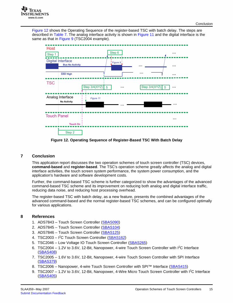
Figure 12 shows the Operating Sequence of the register-based TSC with batch delay. The steps aredescribed in Table 7. The analog interface activity is shown in Figure 11 and the digital interface is thesame as that in Figure 9 (TSC2004 example).
Figure 12. Operating Sequence of Register-Based TSC With Batch Delay
This application report discusses the two operation schemes of touch screen controller (TSC) devices,command-based and register-based. The TSC's operation scheme greatly affects the analog and digitalinterface activities, the touch screen system performance, the system power consumption, and theapplication's hardware and software development costs.
Further, the command-based TSC scheme is further categorized to show the advantages of the advancedcommand-based TSC scheme and its improvement on reducing both analog and digital interface traffic,reducing data noise, and reducing host processing overhead.
The register-based TSC with batch delay, as a new feature, presents the combined advantages of theadvanced command-based and the normal register-based TSC schemes, and can be configured optimallyfor various applications.
1. ADS7843 – Touch Screen Controller (SBAS090)2. ADS7845 – Touch Screen Controller (SBAS104)3. ADS7846 – Touch Screen Controller (SBAS125)4. TSC2003 – I2C Touch Screen Controller (SBAS162)5. TSC2046 – Low Voltage IO Touch Screen Controller (SBAS265)6. TSC2004 – 1.2V to 3.6V, 12-Bit, Nanopower, 4-wire Touch Screen Controller with I2C Interface
(SBAS408)7. TSC2005 – 1.6V to 3.6V, 12-Bit, Nanopower, 4-wire Touch Screen Controller with SPI Interface
(SBAS379)8. TSC2006 – Nanopower, 4-wire Touch Screen Controller with SPI™ Interface (SBAS415)9. TSC2007 – 1.2V to 3.6V, 12-Bit, Nanopower, 4-Wire Micro Touch Screen Controller with I2C Interface
(SBAS405)
SLAA359–May 2007 Operation Schemes of Touch Screen Controllers 15Submit Documentation Feedback

www.ti.com
9 Glossary
Glossary
Data unit - group of bits treated as a unit, which can be 8 bits, 10 bits, or 12 bits in typical TSC devices.
Sample set - complete set of coordinates treated as a set. A sample set may include X, Y, Z1, and Z2. Asample set contains multiple data units.
SSPS - sample sets per second.
MAVF - median value and averaging filter. The TSC2007 automatically collects 7 data units oftouch-screen data, and transmits a single refined data set to the host system.
16 Operation Schemes of Touch Screen Controllers SLAA359–May 2007Submit Documentation Feedback
IMPORTANT NOTICE
Texas Instruments Incorporated and its subsidiaries (TI) reserve the right to make corrections, modifications, enhancements,improvements, and other changes to its products and services at any time and to discontinue any product or service without notice.Customers should obtain the latest relevant information before placing orders and should verify that such information is current andcomplete. All products are sold subject to TI’s terms and conditions of sale supplied at the time of order acknowledgment.
TI warrants performance of its hardware products to the specifications applicable at the time of sale in accordance with TI’sstandard warranty. Testing and other quality control techniques are used to the extent TI deems necessary to support thiswarranty. Except where mandated by government requirements, testing of all parameters of each product is not necessarilyperformed.
TI assumes no liability for applications assistance or customer product design. Customers are responsible for their products andapplications using TI components. To minimize the risks associated with customer products and applications, customers shouldprovide adequate design and operating safeguards.
TI does not warrant or represent that any license, either express or implied, is granted under any TI patent right, copyright, maskwork right, or other TI intellectual property right relating to any combination, machine, or process in which TI products or servicesare used. Information published by TI regarding third-party products or services does not constitute a license from TI to use suchproducts or services or a warranty or endorsement thereof. Use of such information may require a license from a third party underthe patents or other intellectual property of the third party, or a license from TI under the patents or other intellectual property of TI.
Reproduction of information in TI data books or data sheets is permissible only if reproduction is without alteration and isaccompanied by all associated warranties, conditions, limitations, and notices. Reproduction of this information with alteration is anunfair and deceptive business practice. TI is not responsible or liable for such altered documentation.
Resale of TI products or services with statements different from or beyond the parameters stated by TI for that product or servicevoids all express and any implied warranties for the associated TI product or service and is an unfair and deceptive businesspractice. TI is not responsible or liable for any such statements.
TI products are not authorized for use in safety-critical applications (such as life support) where a failure of the TI product wouldreasonably be expected to cause severe personal injury or death, unless officers of the parties have executed an agreementspecifically governing such use. Buyers represent that they have all necessary expertise in the safety and regulatory ramificationsof their applications, and acknowledge and agree that they are solely responsible for all legal, regulatory and safety-relatedrequirements concerning their products and any use of TI products in such safety-critical applications, notwithstanding anyapplications-related information or support that may be provided by TI. Further, Buyers must fully indemnify TI and itsrepresentatives against any damages arising out of the use of TI products in such safety-critical applications.
TI products are neither designed nor intended for use in military/aerospace applications or environments unless the TI products arespecifically designated by TI as military-grade or "enhanced plastic." Only products designated by TI as military-grade meet militaryspecifications. Buyers acknowledge and agree that any such use of TI products which TI has not designated as military-grade issolely at the Buyer's risk, and that they are solely responsible for compliance with all legal and regulatory requirements inconnection with such use.
TI products are neither designed nor intended for use in automotive applications or environments unless the specific TI productsare designated by TI as compliant with ISO/TS 16949 requirements. Buyers acknowledge and agree that, if they use anynon-designated products in automotive applications, TI will not be responsible for any failure to meet such requirements.
Following are URLs where you can obtain information on other Texas Instruments products and application solutions:
Products Applications
Amplifiers amplifier.ti.com Audio www.ti.com/audio
Data Converters dataconverter.ti.com Automotive www.ti.com/automotive
DSP dsp.ti.com Broadband www.ti.com/broadband
Interface interface.ti.com Digital Control www.ti.com/digitalcontrol
Logic logic.ti.com Military www.ti.com/military
Power Mgmt power.ti.com Optical Networking www.ti.com/opticalnetwork
Microcontrollers microcontroller.ti.com Security www.ti.com/security
RFID www.ti-rfid.com Telephony www.ti.com/telephony
Low Power www.ti.com/lpw Video & Imaging www.ti.com/videoWireless
Wireless www.ti.com/wireless
Mailing Address: Texas Instruments, Post Office Box 655303, Dallas, Texas 75265Copyright © 2007, Texas Instruments Incorporated