operation - ucozvu67.ucoz.ru/tnvd_denco.pdfaccelerator position sensor other sensors and switches...
TRANSCRIPT

Common Rail System
Operation
00400076E
© 2004 DENSO CORPORATIONAll Rights Reserved. This book may not be reproducedor copied, in whole or in part, without the writtenpermission of the publisher.


TABLE OF CONTENTS
1. GENERAL DESCRIPTION . . . . . . . . . . . . . . . . . . . . . . . . . . . . . . . . . . . . . . . . . . . . . . . . . . . . . . . . . . . . . . . . . . . . . . . . . . . . . . . 1
1-1. CHANGES IN ENVIRONMENT SURROUNDING THE DIESEL ENGINE . . . . . . . . . . . . . . . . . . . . . . . . . . . . . . . . . . . . . . . 1
1-2. DEMANDS ON FUEL INJECTION SYSTEM . . . . . . . . . . . . . . . . . . . . . . . . . . . . . . . . . . . . . . . . . . . . . . . . . . . . . . . . . . . . . 1
1-3. TYPES OF AND TRANSITIONS IN ECD (ELECTRONICALLY CONTROLLED DIESEL) SYSTEMS . . . . . . . . . . . . . . . . . 2
1-4. COMMON RAIL SYSTEM CHARACTERISTICS . . . . . . . . . . . . . . . . . . . . . . . . . . . . . . . . . . . . . . . . . . . . . . . . . . . . . . . . . . 3
1-5. COMMON RAIL SYSTEM AND SUPPLY PUMP TRANSITIONS . . . . . . . . . . . . . . . . . . . . . . . . . . . . . . . . . . . . . . . . . . . . . . 4
1-6. INJECTOR TRANSITIONS . . . . . . . . . . . . . . . . . . . . . . . . . . . . . . . . . . . . . . . . . . . . . . . . . . . . . . . . . . . . . . . . . . . . . . . . . . . 4
1-7. COMMON RAIL SYSTEM CONFIGURATION . . . . . . . . . . . . . . . . . . . . . . . . . . . . . . . . . . . . . . . . . . . . . . . . . . . . . . . . . . . . 5
2. COMMON RAIL SYSTEM OUTLINE . . . . . . . . . . . . . . . . . . . . . . . . . . . . . . . . . . . . . . . . . . . . . . . . . . . . . . . . . . . . . . . . . . . . . . . 6
2-1. GENERAL DESCRIPTION . . . . . . . . . . . . . . . . . . . . . . . . . . . . . . . . . . . . . . . . . . . . . . . . . . . . . . . . . . . . . . . . . . . . . . . . . . . 6
3. DESCRIPTION OF MAIN COMPONENTS . . . . . . . . . . . . . . . . . . . . . . . . . . . . . . . . . . . . . . . . . . . . . . . . . . . . . . . . . . . . . . . . . . 11
3-1. SUPPLY PUMP . . . . . . . . . . . . . . . . . . . . . . . . . . . . . . . . . . . . . . . . . . . . . . . . . . . . . . . . . . . . . . . . . . . . . . . . . . . . . . . . . . . 11
3-2. RAIL . . . . . . . . . . . . . . . . . . . . . . . . . . . . . . . . . . . . . . . . . . . . . . . . . . . . . . . . . . . . . . . . . . . . . . . . . . . . . . . . . . . . . . . . . . . . 41
3-3. INJECTOR . . . . . . . . . . . . . . . . . . . . . . . . . . . . . . . . . . . . . . . . . . . . . . . . . . . . . . . . . . . . . . . . . . . . . . . . . . . . . . . . . . . . . . . 45
4. DESCRIPTION OF CONTROL SYSTEM COMPONENTS . . . . . . . . . . . . . . . . . . . . . . . . . . . . . . . . . . . . . . . . . . . . . . . . . . . . . . 53
4-1. ENGINE CONTROL SYSTEM DIAGRAM (REFERENCE) . . . . . . . . . . . . . . . . . . . . . . . . . . . . . . . . . . . . . . . . . . . . . . . . . 53
4-2. ENGINE ECU (ELECTRONIC CONTROL UNIT) . . . . . . . . . . . . . . . . . . . . . . . . . . . . . . . . . . . . . . . . . . . . . . . . . . . . . . . . . 54
4-3. EDU (ELECTRONIC DRIVING UNIT) . . . . . . . . . . . . . . . . . . . . . . . . . . . . . . . . . . . . . . . . . . . . . . . . . . . . . . . . . . . . . . . . . . 54
4-4. VARIOUS SENSORS . . . . . . . . . . . . . . . . . . . . . . . . . . . . . . . . . . . . . . . . . . . . . . . . . . . . . . . . . . . . . . . . . . . . . . . . . . . . . . 55
5. CONTROL SYSTEMS . . . . . . . . . . . . . . . . . . . . . . . . . . . . . . . . . . . . . . . . . . . . . . . . . . . . . . . . . . . . . . . . . . . . . . . . . . . . . . . . . . 60
5-1. FUEL INJECTION CONTROL . . . . . . . . . . . . . . . . . . . . . . . . . . . . . . . . . . . . . . . . . . . . . . . . . . . . . . . . . . . . . . . . . . . . . . . . 60
5-2. E-EGR SYSTEM (ELECTRIC-EXHAUST GAS RECIRCULATION) . . . . . . . . . . . . . . . . . . . . . . . . . . . . . . . . . . . . . . . . . . . 69
5-3. ELECTRONICALLY CONTROLLED THROTTLE (NOT MADE BY DENSO) . . . . . . . . . . . . . . . . . . . . . . . . . . . . . . . . . . . 71
5-4. EXHAUST GAS CONTROL SYSTEM . . . . . . . . . . . . . . . . . . . . . . . . . . . . . . . . . . . . . . . . . . . . . . . . . . . . . . . . . . . . . . . . . . 72
5-5. DPF SYSTEM (DIESEL PARTICULATE FILTER) . . . . . . . . . . . . . . . . . . . . . . . . . . . . . . . . . . . . . . . . . . . . . . . . . . . . . . . . . 73
5-6. DPNR SYSTEM (DIESEL PARTICULATE NOx REDUCTION) . . . . . . . . . . . . . . . . . . . . . . . . . . . . . . . . . . . . . . . . . . . . . . 75
6. DIAGNOSIS . . . . . . . . . . . . . . . . . . . . . . . . . . . . . . . . . . . . . . . . . . . . . . . . . . . . . . . . . . . . . . . . . . . . . . . . . . . . . . . . . . . . . . . . . . 76
6-1. OUTLINE OF THE DIAGNOSTIC FUNCTION . . . . . . . . . . . . . . . . . . . . . . . . . . . . . . . . . . . . . . . . . . . . . . . . . . . . . . . . . . . 76
6-2. DIAGNOSIS INSPECTION USING DST-1 . . . . . . . . . . . . . . . . . . . . . . . . . . . . . . . . . . . . . . . . . . . . . . . . . . . . . . . . . . . . . . 76
6-3. DIAGNOSIS INSPECTION USING THE MALFUNCTION INDICATOR LIGHT . . . . . . . . . . . . . . . . . . . . . . . . . . . . . . . . . . 77
6-4. THROTTLE BODY FUNCTION INSPECTION . . . . . . . . . . . . . . . . . . . . . . . . . . . . . . . . . . . . . . . . . . . . . . . . . . . . . . . . . . . 79
7. END OF VOLUME MATERIALS . . . . . . . . . . . . . . . . . . . . . . . . . . . . . . . . . . . . . . . . . . . . . . . . . . . . . . . . . . . . . . . . . . . . . . . . . . 80
7-1. PARTICULATE MATTER (PM) . . . . . . . . . . . . . . . . . . . . . . . . . . . . . . . . . . . . . . . . . . . . . . . . . . . . . . . . . . . . . . . . . . . . . . . 80
7-2. COMMON RAIL TYPE FUEL INJECTION SYSTEM DEVELOPMENT HISTORY AND THE WORLD'S MANUFACTURERS . . . . . . . . . . . . . . . . . . . . . . . . . . . . . . . . . . . . . . . . . . . . . . . . . . . . . . . . . . . . . . . . . . . . . . . . . . . . . . . 80
7-3. HIGHER INJECTION PRESSURE, OPTIMIZED INJECTION RATES, HIGHER INJECTION TIMING CONTROL PRECISION, HIGHER INJECTION QUANTITY CONTROL PRECISION . . . . . . . . . . . . . . . . . . . . . . . . . . . . . . . . . . . . . . 80
7-4. IMAGE OF COMBUSTION CHAMBER INTERIOR . . . . . . . . . . . . . . . . . . . . . . . . . . . . . . . . . . . . . . . . . . . . . . . . . . . . . . . 82

1. GENERAL DESCRIPTION
1-1. CHANGES IN ENVIRONMENT SURROUNDING THE DIESEL ENGINE• Throughout the world, there is a desperate need to improve vehicle fuel economy for the purposes of preventing global
warming and reducing exhaust gas emissions that affect human health. Diesel engine vehicles are highly acclaimed in
Europe, due to the good fuel economy that diesel fuel offers. On the other hand, the "nitrogen oxides (NOx)" and "par-
ticulate matter (PM)" contained in the exhaust gas must be greatly reduced to meet exhaust gas regulations, and tech-
nology is being actively developed for the sake of improved fuel economy and reduced exhaust gases.
< NOTE >• For more information on particulate matter (PM), see the material at the end of this document.
A. Demands on Diesel Vehicles• Reduce exhaust gases (NOx, PM, carbon monoxide (CO), hydrocarbon (HC) and smoke).
• Improve fuel economy.
• Reduce noise.
• Improve power output and driving performance.
B. Transition of Exhaust Gas Regulations (Example of Large Vehicle Diesel Regulations)The EURO IV regulations take effect in Europe from 2005, and the 2004 MY regulations take effect in North America
from 2004. Furthermore, the EURO V regulations will take effect in Europe from 2008, and the 2007 MY regulations will
take effect in North America from 2007. Through these measures, PM and NOx emissions are being reduced in stages.
1-2. DEMANDS ON FUEL INJECTION SYSTEM• In order to address the various demands that are imposed on diesel vehicles, the fuel injection system (including the
injection pump and nozzles) plays a significant role because it directly affects the performance of the engine and the
vehicle. Some of the demands are: higher injection pressure, optimized injection rate, higher precision of injection timing
control, and higher precision of injection quantity control.
< NOTE >• For further information on higher injection pressure, optimized injection rate, higher precision of injection timing control,
and higher precision of injection quantity control, see the material at the end of this document.
Q000989E
PM
g/kWh
NOx
g/kWh
2005 20082004 2007
3.5
2.0
2.7
0.27
1998 MY 2004 MY 2007 MY
EURO EURO EURO EURO EURO EURO
1998 MY 2004 MY 2007 MY
0.013
0.130.11
0.03
Europe Europe
North America
North
America
2005 20082004 2007
-1-
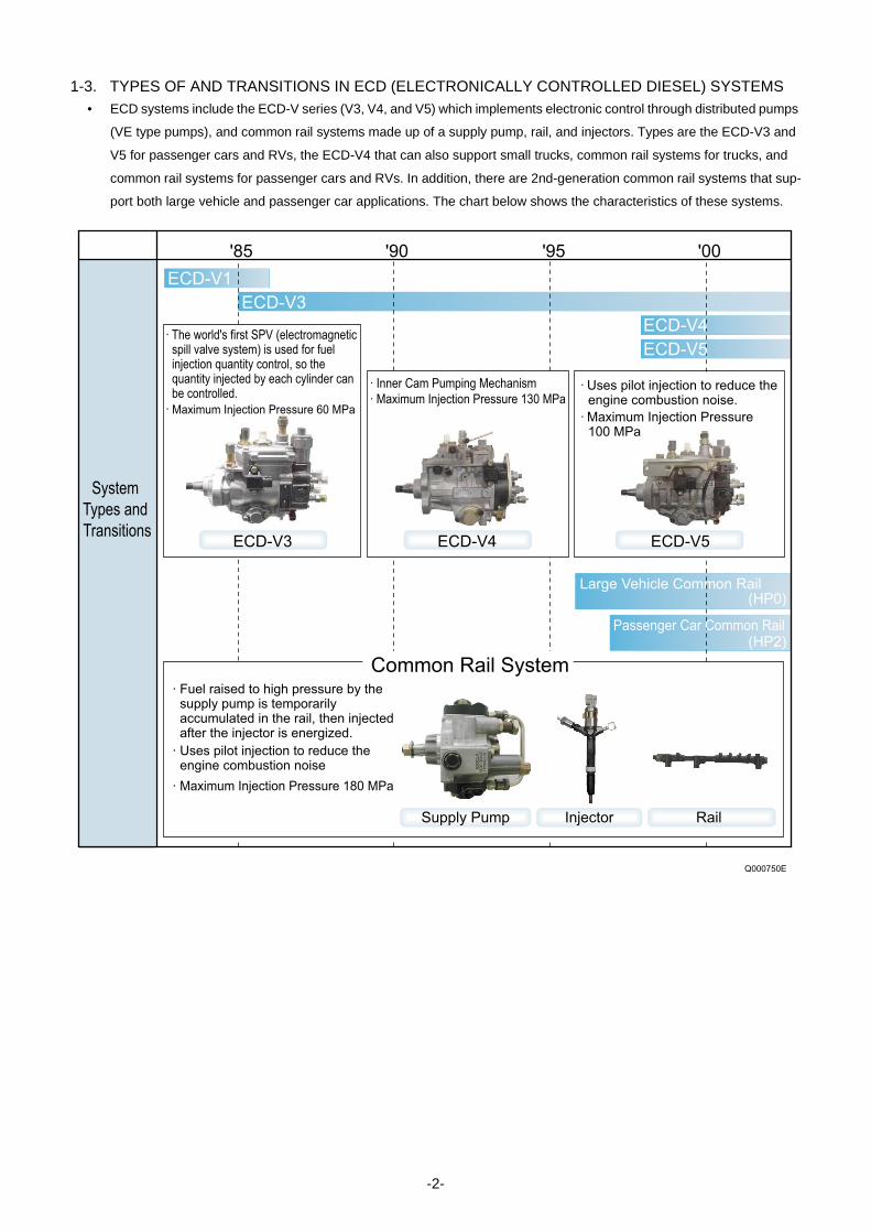
1-3. TYPES OF AND TRANSITIONS IN ECD (ELECTRONICALLY CONTROLLED DIESEL) SYSTEMS • ECD systems include the ECD-V series (V3, V4, and V5) which implements electronic control through distributed pumps
(VE type pumps), and common rail systems made up of a supply pump, rail, and injectors. Types are the ECD-V3 and
V5 for passenger cars and RVs, the ECD-V4 that can also support small trucks, common rail systems for trucks, and
common rail systems for passenger cars and RVs. In addition, there are 2nd-generation common rail systems that sup-
port both large vehicle and passenger car applications. The chart below shows the characteristics of these systems.
ECD-V1
ECD-V3
ECD-V4
ECD-V5
'85 '90 '95 '00
Large Vehicle Common Rail(HP0)
(HP2)Passenger Car Common Rail
Common Rail System
· Maximum Injection Pressure 180 MPa
· Uses pilot injection to reduce the engine combustion noise
· Fuel raised to high pressure by the supply pump is temporarily accumulated in the rail, then injected after the injector is energized.
System
Types and
Transitions
· Maximum Injection Pressure 130 MPa
· Inner Cam Pumping Mechanism
· Maximum Injection Pressure 100 MPa
· Uses pilot injection to reduce the engine combustion noise.
Supply Pump Injector Rail
· The world's first SPV (electromagnetic spill valve system) is used for fuel injection quantity control, so the quantity injected by each cylinder can be controlled.
· Maximum Injection Pressure 60 MPa
Q000750E
ECD-V3 ECD-V4 ECD-V5
-2-

1-4. COMMON RAIL SYSTEM CHARACTERISTICS• The common rail system uses a type of accumulation chamber called a rail to store pressurized fuel, and injectors that
contain electronically controlled solenoid valves to inject the pressurized fuel into the cylinders.
• Because the engine ECU controls the injection system (including the injection pressure, injection rate, and injection tim-
ing), the injection system is independent and thus unaffected by the engine speed or load.
• Because the engine ECU can control injection quantity and timing to a high level of precision, even multi-injection (mul-
tiple fuel injections in one injection stroke) is possible.
• This ensures a stable injection pressure at all times, even in the low engine speed range, and dramatically decreases
the amount of black smoke ordinarily emitted by a diesel engine during start-up and acceleration. As a result, exhaust
gas emissions are cleaner and reduced, and higher power output is achieved.
< NOTE >• For the background of common rail fuel injection systems, see the materials at the end of this document.
A. Features of Injection Controla. Injection Pressure Control
• Enables high-pressure injection even at low engine speeds.
• Optimizes control to minimize particulate matter and NOx emissions.
b. Injection Timing Control
Enables finely tuned optimized control in accordance with driving conditions.
c. Injection Rate Control
Pilot injection control injects a small amount of fuel before the main injection.
· Injection pressure is more than double the current pressure, which makes it possible to greatly reduce particulate matter.
Common Rail System
Injection Pressure Control Injection Timing Control Injection Rate Control
Injection Quantity Control
Electronic Control Type
Common Rail System
Conventional
Pump
Optimized and Higher Pressure
Speed
Speed
Injection Quantity
Injection Pressure
Pre-Injection
Pilot injection After-Injection
Post-Injection
Main Injection
1 3 2 4
Inje
ctio
n P
ressu
re
Pa
rtic
ula
te
Inje
ctio
n R
ate
Crankshaft Angle
Cylinder Injection Quantity Correction
Inje
ctio
n Q
uant
ity
Adv
ance
Ang
le
Q000751E
-3-

1-5. COMMON RAIL SYSTEM AND SUPPLY PUMP TRANSITIONS• The world's first common rail system for trucks was introduced in 1995. In 1999, the common rail system for passenger
cars (the HP2 supply pump) was introduced, and then in 2001 a common rail system using the HP3 pump (a lighter and
more compact supply pump) was introduced. In 2004, the three-cylinder HP4 based on the HP3 was introduced.
A. Supply Pump Types and Transitions
1-6. INJECTOR TRANSITIONS
Q000752E
1996 1998 2000 2002 2004 2006
120MPa
180MPa
135MPa
HP0
HP2HP3
Large Trucks
Medium-Size Trucks
Common Rail
System1st Generation Common Rail System 2nd Generation Common Rail System
Passenger Vehicles
Compact Trucks
Suction Quantity Adjustment
Suction Quantity Adjustment
Suction Quantity Adjustment
Pre-Stroke Quantity Adjustment180MPa
HP4
Q000753E
· 180MPa
· 135MPa
· 120MPa
X1 G2
97 98 99 00 01 02 03
1st Generation 2nd Generation
· Multi-Injection
· Pilot Injection
· Pilot Injection
X2
-4-

1-7. COMMON RAIL SYSTEM CONFIGURATION• The common rail control system can be broadly divided into the following four areas: sensors, engine ECU, EDU, and
actuators.
A. SensorsDetect the condition of the engine and the pump.
B. Engine ECUReceives signals from the sensors, calculates the proper injection quantity and injection timing for optimal engine oper-
ation, and sends the appropriate signals to the actuators.
C. EDUEnables the injectors to be actuated at high speeds. There are also types with charge circuits within the ECU that serve
the same role as the EDU. In this case, there is no EDU.
D. ActuatorsOperate to provide optimal injection quantity and injection timing in accordance with the signals received from the engine
ECU.
Engine Speed Sensor /
TDC (G) Sensor
Accelerator Position Sensor
Other Sensors and Switches
Engine ECU
EDU
Supply Pump (SCV: Suction Control Valve)
Injector
Other Actuators
DiagnosisQ000754E
-5-

2. COMMON RAIL SYSTEM OUTLINE
2-1. GENERAL DESCRIPTION• Common rail systems are mainly made up of the supply pump, rail, and injectors. There are the following types according
to the supply pump used.
A. HP0 TypeThis system is the first common rail system that DENSO commercialized. It uses an HP0 type supply pump and is mount-
ed in large trucks and large buses.
a. Exterior View of Main System Components
b. Configuration of Main System Components (Example of HP0)
< NOTE >• For details on the configuration, see the control part explanations and engine control system diagram items.
Q000755E
InjectorSupply Pump (HP0 Type)
Rail
Q000756E
Supply Pump
PCV (Pump Control Valve)
Cylinder
Recognition Sensor
(TDC (G) Sensor)
Rail Pressure Sensor
Rail
Engine ECU
Injector
Accelerator
Position Sensor
Crankshaft Position Sensor (Engine Speed Sensor)
Fuel Temperature Sensor
Coolant Temperature
Sensor
-6-

B. HP2 TypeThis system uses a type of HP2 supply pump that has been made lighter and more compact, and is the common rail
system for passenger cars and RVs instead of the ECD-V3.
a. Exterior View of Main System Components
b. Mounting Diagram for Main System Components
Q000757E
InjectorSupply Pump (HP2 Type)
Rail
Engine ECU
EDU (Electronic Driving Unit)
EGR Valve
E-VRV
Intake Air Temperature
Sensor
Intake Air Pressure Sensor
Injector
Crankshaft Position Sensor
(Engine Speed Sensor) RailSupply Pump Cylinder Recognition Sensor
(TDC (G) Sensor)
Rail Pressure Sensor
Accelerator Position Sensor
Coolant Temperature
Sensor
Q000758E
-7-

c. Overall System Flow (Fuel)
Q000926E
Supply Pump
PlungerFeed Pump
Delivery Valve
SCV (Suction Control Valve)
Inner Cam
Regulating Valve
Check Valve
RailRail Pressure Sensor
Pressure Limiter
Injector
TWV
Engine
ECUEDUVarious Sensors
Fuel Filter
Fuel Tank
: Flow of Injection Fuel
: Flow of Leak Fuel
-8-

C. HP3 Type, HP4 Typea. HP3 Type
This system uses an HP3 type supply pump that is compact, lightweight and provides higher pressure. It is mostly
mounted in passenger cars and small trucks.
b. HP4 Type
This system is basically the same as the HP3 type, however it uses the HP4 type supply pump, which has an increased
pumping quantity to handle larger engines. This system is mostly mounted in medium-size trucks.
c. Exterior View of Main System Components
d. Mounting Diagram for Main System Components
Q000759E
HP3 HP4
InjectorSupply Pump
Rail
Q000760E
Supply Pump
SCV (Suction Control
Valve)
Fuel Temperature Sensor
Fuel Temperature Sensor
Injector
Engine ECU
EDU
DLC3 Connector
R/B
EGR Valve E-VRV for EGR
EGR Shut-Off VSV
Throttle Body
Crankshaft Position Sensor (Engine Speed Sensor)
Cylinder Recognition Sensor (TDC (G) Sensor)
Accelerator Position Sensor
Intake Air Pressure Sensor
Airflow Meter (with Intake Air
Temperature Sensor)
Coolant Temperature Sensor
HP3 HP4
(Suction Control Valve)
SCV
Pressure Discharge Valve
Rail Pressure Sensor
-9-

e. Overall System Flow (Fuel)
Q000927E
Supply Pump
(HP3 or HP4)
Plunger
Feed Pump
Delivery
Valve
SCV (Suction
Control Valve)
Rail
Rail Pressure Sensor
Pressure Discharge Valve
Pressure Limiter
Injector
ECU
EDU
Various Sensors
Fuel Filter
Fuel Tank
: Flow of Injection Fuel
: Flow of Leak Fuel
-10-

3. DESCRIPTION OF MAIN COMPONENTS
3-1. SUPPLY PUMP
A. HP0 Typea. Construction and Characteristics
• The HP0 supply pump is mainly made up of a pumping system as in conventional in-line pumps (two cylinders), the PCV
(Pump Control Valve) for controlling the fuel discharge quantity, the cylinder recognition sensor (TDC (G) sensor), and
the feed pump.
• It supports the number of engine cylinders by changing the number of peaks on the cam. The supply pump rotates at
half the speed of the engine. The relationship between the number of engine cylinders and the supply pump pumping is
as shown in the table below.
• By increasing the number of cam peaks to handle the number of engine cylinders, a compact, two-cylinder pump unit is
achieved. Furthermore, because this pump has the same number of pumping strokes as injections, it maintains a smooth
and stable rail pressure.
Number of Engine Cylinders Speed Ratio (Pump: Engine)
Supply Pump Number of Pumping Rotations
for 1 Cycle of the Engine
(2 Rotations)
Number of
CylindersCam Peaks
4 Cylinders
1 : 2 2
2 4
6 Cylinders 3 6
8 Cylinders 4 8
Feed Pump
Delivery Valve
Cam x 2
PCV (Pump Control Valve)
Tappet
Element
Cylinder Recognition Sensor
(TDC (G) Sensor)
Pulsar for TDC (G) Sensor
Overflow Valve
Q000768E
-11-

b. Exploded View
Q000769E
PCV
(Pump Control Valve)
Delivery ValveElement
Cylinder Recognition Sensor
(TDC (G) Sensor)
RollerCam
Camshaft
Tappet
Feed Pump
Priming Pump
-12-

c. Supply Pump Component Part Functions
(1) Feed Pump
The feed pump, which is integrated in the supply pump, draws fuel from the fuel tank and feeds it to the pump chamber
via the fuel filter. There are two types of feed pumps, the trochoid type and the vane type.
A) Trochoid Type
The camshaft actuates the outer/inner rotors of the feed pump, causing them to start rotating. In accordance with the
space produced by the movement of the outer/inner rotors, the feed pump draws fuel into the suction port and pumps
fuel out the discharge port.
B) Vane Type
The camshaft actuates the feed pump rotor and the vanes slide along the inner circumference of the eccentric ring. Along
with the rotation of the rotor, the pump draws fuel from the fuel tank, and discharges it to the SCV and the pumping mech-
anism.
Component Parts Functions
Feed Pump Draws fuel from the fuel tank and feeds it to the pumping mechanism.
Overflow Valve Regulates the pressure of the fuel in the supply pump.
PCV (Pump Control Valve) Controls the quantity of fuel delivered to the rail.
Pumping
Mechanism
Cam Actuates the tappet.
Tappet Transmits reciprocating motion to the plunger.
Plunger Moves reciprocally to draw and compress fuel.
Delivery Valve Stops the reverse flow of fuel pumped to the rail.
Cylinder Recognition Sensor (TDC (G)
Sensor)
Identifies the engine cylinders.
To Pump Chamber
From Fuel Tank
Outer Rotor
Inner Rotor
Suction Port Discharge Port
Q000770E
Suction Port
Discharge Port
Rotor Eccentric Ring
Vane
Q000771E
-13-

(2) PCV : Pump Control Valve
The PCV (Pump Control Valve) regulates the fuel discharge quantity from the supply pump in order to regulate the rail
pressure. The fuel quantity discharged from the supply pump to the rail is determined by the timing with which the current
is applied to the PCV.
A) Actuation Circuit
The diagram below shows the actuation circuit of the PCV. The ignition switch turns the PCV relay ON and OFF to apply
current to the PCV. The ECU handles ON/OFF control of the PCV. Based on the signals from each sensor, it determines
the target discharge quantity required to provide optimum rail pressure and controls the ON/OFF timing for the PCV to
achieve this target discharge quantity.
(3) Pumping Mechanism
The camshaft is actuated by the engine and the cam actuates the plunger via the tappet to pump the fuel sent by the
feed pump. The PCV controls the discharge quantity. The fuel is pumped from the feed pump to the cylinder, and then
to the delivery valve.
PCV
Ignition Switch
+B
PCV Relay
PCV1
PCV2
From PCV relay
To Rail
Q000772E
Q000773E
Camshaft
Feed Pump
PCV (Pump Control Valve)
Pulsar for TDC (G) Sensor
Delivery Valve
Cam (3 Lobes: 6-Cylinders)
Plunger
To Rail
-14-

(4) CYLINDER RECOGNITION SENSOR (TDC (G) SENSOR)
The cylinder recognition sensor (TDC (G) sensor) uses the alternating current voltage generated by the change in the
lines of magnetic force passing through the coil to send the output voltage to the ECU. This is the same for the engine
speed sensor installed on the engine side. A disc-shaped gear, which is provided in the center of the supply pump cam-
shaft, has cutouts that are placed at 120° intervals, plus an extra cutout. Therefore, this gear outputs seven pulses for
every two revolutions of the engine (for a six-cylinder engine). Through the combination of engine-side engine speed
pulses and TDC pulses, the pulse after the extra cutout pulse is recognized as the No. 1 cylinder.
Q000774E
0 2 4 6 8 101214 0 2 4 6 810 12 14 0 2 4 6 8 10 12 0 2 4 6 8 101214 0 2 4 6 8 101214 0 2 4 6 8 0 2 4 6 81012
Cylinder Recognition Sensor
(TDC (G) Sensor)
No.6 Cylinder TDC (G) Standard Pulse No.1 Cylinder Recognition TDC (G) Pulse
No.1 Cylinder TDC (G) Pulse
No.1 Cylinder Engine Speed Standard Pulse No.6 Cylinder Engine Speed Standard Pulse
· TDC (G) Pulse
· Engine Speed Pulse
· For a 6-Cylinder Engine (Reference)
-15-
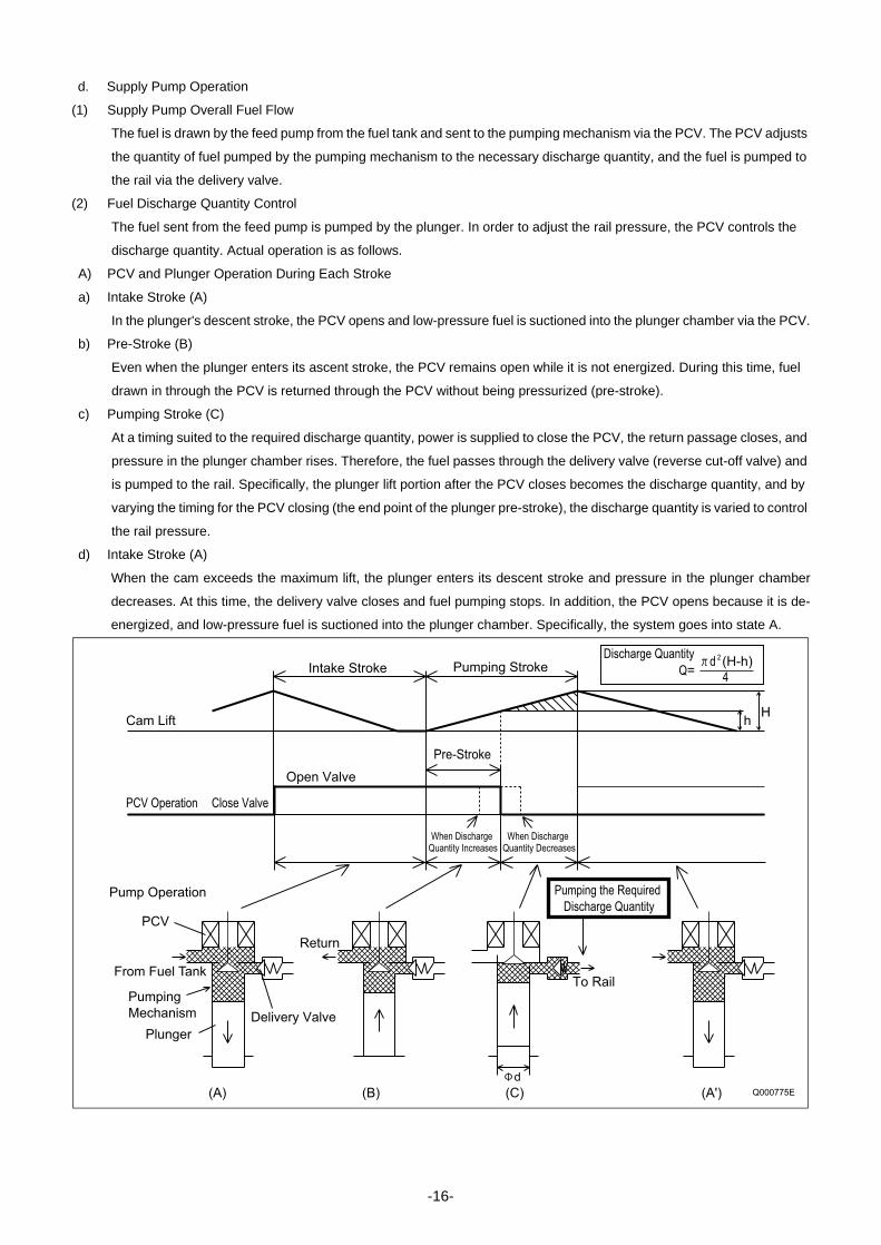
d. Supply Pump Operation
(1) Supply Pump Overall Fuel Flow
The fuel is drawn by the feed pump from the fuel tank and sent to the pumping mechanism via the PCV. The PCV adjusts
the quantity of fuel pumped by the pumping mechanism to the necessary discharge quantity, and the fuel is pumped to
the rail via the delivery valve.
(2) Fuel Discharge Quantity Control
The fuel sent from the feed pump is pumped by the plunger. In order to adjust the rail pressure, the PCV controls the
discharge quantity. Actual operation is as follows.
A) PCV and Plunger Operation During Each Stroke
a) Intake Stroke (A)
In the plunger's descent stroke, the PCV opens and low-pressure fuel is suctioned into the plunger chamber via the PCV.
b) Pre-Stroke (B)
Even when the plunger enters its ascent stroke, the PCV remains open while it is not energized. During this time, fuel
drawn in through the PCV is returned through the PCV without being pressurized (pre-stroke).
c) Pumping Stroke (C)
At a timing suited to the required discharge quantity, power is supplied to close the PCV, the return passage closes, and
pressure in the plunger chamber rises. Therefore, the fuel passes through the delivery valve (reverse cut-off valve) and
is pumped to the rail. Specifically, the plunger lift portion after the PCV closes becomes the discharge quantity, and by
varying the timing for the PCV closing (the end point of the plunger pre-stroke), the discharge quantity is varied to control
the rail pressure.
d) Intake Stroke (A)
When the cam exceeds the maximum lift, the plunger enters its descent stroke and pressure in the plunger chamber
decreases. At this time, the delivery valve closes and fuel pumping stops. In addition, the PCV opens because it is de-
energized, and low-pressure fuel is suctioned into the plunger chamber. Specifically, the system goes into state A.
Q000775E
Cam Lift
PCV Operation Close Valve
Intake Stroke Pumping Stroke
Pre-Stroke
Open Valve
PCV
Pump Operation
Plunger
Return
When Discharge Quantity Increases
When Discharge Quantity Decreases
To Rail
Pumping the Required
Discharge Quantity
H
Discharge Quantity
h
Q=4
2d (H-h)
(A) (B) (C) (A')
Delivery Valve
From Fuel Tank
Pumping
Mechanism
d
-16-

B. HP2 Typea. Construction and Characteristics
• The supply pump is primarily composed of the two pumping mechanism (inner cam, roller, two plungers) systems, the
SCV (Suction Control Valve), the fuel temperature sensor, and the feed pump (vane type), and is actuated with half the
engine rotation.
• The pumping mechanism consists of an inner cam and a plunger, and forms a tandem configuration in which two systems
are arranged axially. This makes the supply pump compact and reduces the peak torque.
• The quantity of fuel discharged to the rail is controlled by the fuel suction quantity using SCV (Suction Control Valve)
control. In order to control the discharge quantity with the suction quantity, excess pumping operations are eliminated,
reducing the actuation load and suppressing the rise in fuel temperature.
b. Supply Pump Actuating Torque
Because the pumping mechanism is a tandem configuration, its peak actuating torque is one-half that of a single pump
with the same discharge capacity.
Regulating Valve
Plunger
Feed Pump
Inner Cam
Roller
Fuel Temperature Sensor
Delivery Valve
SCV (Suction Control Valve)
Check Valve
Overflow
Fuel Suction (From Fuel Tank)
Q000818E
Pumping
Pumping
PumpingSuction
Pumping
Feed
Feed
Plunger 2 Plunger 1
Tor
que
(Oil
Pum
ping
Rat
e)
Tor
que
(Oil
Pum
ping
Rat
e)
Co
mp
ositio
n
Single Type Tandem Type
To
rqu
e P
att
ern
Solid Line : Plunger 1Broken Line: Plunger 2
Q000819E
-17-

c. Exploded View
Pump Body
Feed Pump
Camshaft
Inner Cam
Roller
Shoe
Delivery Valve
SCV (Suction Control Valve)
Check Valve
Fuel Temperature Sensor
Regulating Valve
Q000820E
-18-

d. Component Part Functions
(1) Feed Pump
The feed pump is a four-vaned type that draws fuel from the fuel tank and discharges it to the pumping mechanism. The
rotation of the drive shaft causes the feed pump rotor to rotate and the vane to move by sliding along the inner surface
of the casing (eccentric ring). Along with the rotation of the rotor, the pump draws fuel from the fuel tank, and discharges
it to the SCV and the pumping mechanism. To keep the vane pressed against the inner circumference, a spring is pro-
vided inside each vane, in order to minimize fuel leakage within the pump.
(2) Regulating Valve
The purpose of the regulating valve is to control the feed pressure (fuel pumping pressure) sending fuel to the pumping
mechanism. As the rotational movement of the pump increases and the feed pressure exceeds the pressure set at the
regulating valve, the valve opens by overcoming the spring force, allowing the fuel to return to the suction side.
Component Parts Functions
Feed Pump Draws fuel from the fuel tank and feeds it to the pumping mechanism.
Regulating Valve Regulates internal fuel pressure in the supply pump.
SCV (Suction Control Valve) Controls the quantity of fuel that is fed to the plunger in order to control fuel pressure in the
rail.
Pumping
Mechanism
Inner Cam Actuates the plunger.
Roller Actuates the plunger.
Plunger Moves reciprocally to draw and compress fuel.
Delivery Valve Maintains high pressure by separating the pressurized area (rail) from the pumping mecha-
nism.
Fuel Temperature Sensor Detects the fuel temperature.
Check Valve Prevents the pressurized fuel in the pumping mechanism from flowing back into the suction
side.
Q000821E
Rotor
Eccentric Ring
Spring
Vane
Front Cover Rear Cover
Regulating Valve
Open Valve Pressure Characteristic
Open Valve Pressure High
Open Valve Pressure Low
Speed
Feed P
ress
ure
(P
um
pin
g P
ress
ure
)
Regulating Valve
Feed Pump
(Discharge Side)
Suction Inlet
Filter
Feed Pump
(Suction Side)
Regulating Valve Body
Spring
Piston
BushingQ000822E
-19-

(3) SCV : Suction Control Valve
A solenoid type valve has been adopted. The ECU controls the duration of the current applied to the SCV in order to
control the quantity of fuel drawn into the pumping mechanism. Because only the quantity of fuel required to achieve the
target rail pressure is drawn in, the actuating load of the supply pump decreases, thus improving fuel economy.
A) Operation
a) SCV ON
When current is applied to the coil, it pulls the needle valve upward, allowing fuel to be drawn into the pumping mecha-
nism of the supply pump.
b) SCV OFF
When current is no longer applied to the coil, the needle valve closes and stops the suction of fuel.
Needle Valve
Spring
Stopper Coil
Q000823E
To Pump Pumping Mechanism
From Feed Pump Q000824E
From Feed PumpQ000825E
-20-

(4) Pumping Mechanism (Plunger, Inner Cam, Roller)
• The pumping mechanism is made up of the plunger, inner cam, and roller, and it draws in the fuel discharged by the feed
pump and pumps it to the rail. Because the drive shaft and the inner cam have an integral construction, the rotation of
the drive shaft directly becomes the rotation of the inner cam.
• Two plunger systems are arranged in series (tandem type) inside the inner cam. Plunger 1 is situated horizontally, and
plunger 2 is situated vertically. Plunger 1 and plunger 2 have their suction and compression strokes reversed (when one
is on the intake, the other is discharging), and each plunger discharges twice for each one rotation, so for one rotation
of the supply pump, they discharge a total of four times to the rail.
(5) Delivery Valve
The delivery valve, which contains two valve balls, delivers the pressurized fuel from plungers 1 and 2 to the rail in alter-
nating strokes. When the pressure in the plunger exceeds the pressure in the rail, the valve opens to discharge fuel.
Inner Cam (Cam Lift: 3.4mm)
RollerRoller Diameter: 9Roller Length: 21mmMaterial: Reinforced Ceramic
Plunger 1 (Horizontal)
Plunger 2 (Vertical)
· Plunger 1: Medium + Medium· Plunger 2: Short + Long
Plunger Length Combination
Cam 90 Rotation
Plunger 1: Start of PumpingPlunger 2: Start of Suction
Plunger 1: Start of SuctionPlunger 2: Start of Pumping
Plunger 1
Plunger 2
Q000826E
From Plunger 1
From Plunger 2
Pin
Gasket
Guide
Valve Ball
Stopper Holder
To Rail
· When Plunger 1 Pumping · When Plunger 2 Pumping
Q000827E
-21-

(6) Fuel Temperature Sensor
The fuel temperature sensor is installed on the fuel intake side and utilizes the characteristics of a thermistor in which
the electric resistance changes with the temperature in order to detect the fuel temperature.
(7) Check Valve
The check valve, which is located between the SCV (Suction Control Valve) and the pumping mechanism, prevents the
pressurized fuel in the pumping mechanism from flowing back into the SCV.
A) Check Valve Open
During fuel suction (SCV ON), the feed pressure opens the valve, allowing fuel to be drawn into the pumping mechanism.
B) Check Valve Closed
During fuel pumping (SCV OFF), the pressurized fuel in the pumping mechanism closes the valve, preventing fuel from
flowing back into the SCV.
Resistance - Temperature Characteristic
Temperature Re
sis
tan
ce
Va
lue
Thermistor
Q000828E
Pump Housing Spring Valve
Stopper PlugTo SCV
To Pumping Mechanism
Q000829E
From SCV
To Pumping Mechanism
Q000830E
From Pumping Mechanism
Q000831E
-22-

e. Supply Pump Operation
(1) Supply Pump Overall Fuel Flow
Fuel is suctioned by the feed pump from the fuel tank and sent to the SCV. At this time, the regulating valve adjusts the
fuel pressure to below a certain level. Fuel sent to the feed pump has the required discharge quantity adjusted by the
SCV and enters the pumping mechanism through the check valve. The fuel pumped by the pumping mechanism is
pumped through the delivery valve to the rail.
From Fuel Tank
Feed Pump
Plunger
Cam
Head
SCV2
Check Valve 1
Check Valve 2
SCV1
To Rail
Delivery ValveTo Tank
Overflow Orifice
Regulating Valve
Q000832E
-23-

(2) Fuel Discharge Quantity Control
• The diagram below shows that the suction starting timing (SCV (Suction Control Valve) ON) is constant (determined by
the pump speed) due to the crankshaft position sensor signal. For this reason, the fuel suction quantity is controlled by
changing the suction ending timing (SCV OFF). Hence, the suction quantity decreases when the SCV is turned OFF early
and the quantity increases when the SCV is turned OFF late.
• During the intake stroke, the plunger receives the fuel feed pressure and descends along the cam surface. When the
SCV turns OFF (suction end), the feed pressure on the plunger ends and the descent stops. Since the suction quantity
varies, when suction ends (except for maximum suction) the roller separates from the cam surface.
• When the drive shaft rotates and the cam peak rises and the roller comes in contact with the cam surface again, the
plunger is pressed by the cam and starts pumping. Since the suction quantity = the discharge quantity, the discharge
quantity is controlled by the timing with which the SCV is switched OFF (suction quantity).
0 2 4 6 8 10121416 0 2 4 6 8 101214 0 2 4 6 8 10121416 0 2 4 6 8 101214
Suction Suction
Suction SuctionDecreased Suction Quantity
Increased Suction Quantity
ON
OFFSCV 1
SCV 2
Suction Pumping
Start of Suction End of Suction Start of Pumping End of Pumping
360 CR
TDC #1 TDC #3 TDC #4 TDC #2
Cylinder Recognition Sensor Signal
Crankshaft Position Sensor Signal
ON
OFF
Crankshaft Angle
Compression Top Dead Center
Fuel
ON
Plunger
Roller
OFF
Fuel
OFF
Fuel
OFF
Delivery Valve
Discharge
Horizontal
Cam Lift
Vertical
Cam Lift
Check Valve
SCV
Pumping Suction
Pumping SuctionPumping Suction
Pumping Suction
Delivery Valve
Q000833E
-24-

C. HP3 Typea. Construction and Characteristics
• The supply pump is primarily composed of the pump unit (eccentric cam, ring cam, two plungers), the SCV (suction con-
trol valve), the fuel temperature sensor and the feed pump (trochoid type), and is actuated at 1/1 or 1/2 the engine rota-
tion.
• The two compact pump unit plungers are positioned symmetrically above and below on the outside of the ring cam.
• The fuel discharge quantity is controlled by the SCV, the same as for the HP2, in order to reduce the actuating load and
suppress the rise in fuel temperature. In addition, there are two types of HP3 SCV: the normally open type (the suction
valve opens when not energized) and the normally closed type (the suction valve is closed when not energized).
• With a DPNR system (Diesel Particulate NOx Reduction) system, there is also a flow damper. The purpose of this flow
damper is to automatically shut off the fuel if a leak occurs in the fuel addition valve passage within the DPNR.
Q000835E
Suction Valve
Plunger
Ring Cam SCV (Suction Control Valve)
Delivery Valve
Feed Pump
Fuel Temperature Sensor
-25-

b. Exploded View
Q000836E
Pump Housing
Camshaft
Eccentric Cam
Ring Cam
Feed Pump
Plunger
Element Sub-Assembly
SCV (Suction Control Valve)
Regulating Valve
Fuel Temperature Sensor
Delivery Valve
Delivery Valve
Delivery Valve
Element Sub-Assembly
Plunger
-26-

c. Functions of the Component Parts
(1) Feed Pump
The trochoid type feed pump, which is integrated in the supply pump, draws fuel from the fuel tank and feeds it to the two
plungers via the fuel filter and the SCV (Suction Control Valve). The drive shaft actuates the outer/inner rotors of the feed
pump, thus causing the rotors to start rotating. In accordance with the space that increases and decreases with the move-
ment of the outer and inner rotors, the feed pump draws fuel into the suction port and pumps fuel out the discharge port.
(2) Regulating Valve
The regulating valve keeps the fuel feed pressure (discharge pressure) below a certain level. If the pump speed increas-
es and the feed pressure exceeds the preset pressure of the regulating valve, the valve opens by overcoming the spring
force in order to return the fuel to the suction side.
Component Parts Functions
Feed Pump Draws fuel from the fuel tank and feeds it to the plunger.
Regulating Valve Regulates the pressure of the fuel in the supply pump.
SCV (Suction Control Valve) Controls the quantity of fuel that is fed to the plungers.
Pump Unit
Eccentric Cam Actuates the ring cam.
Ring Cam Actuates the plunger.
Plunger Moves reciprocally to draw and compress fuel.
Suction Valve Prevents reverse flow of compressed fuel into the SCV.
Delivery Valve Prevents reverse flow from the rail of the fuel pumped from the plunger.
Fuel Temperature Sensor Detects the fuel temperature.
To Pump Chamber
From Fuel Tank
Outer Rotor
Inner Rotor
Suction Port Discharge Port
Q000770E
Bushing
Piston
Spring
Plug
Feed Pump
SCV
Pump Housing
Q000837E
-27-

(3) SCV : Suction Control Valve
The HP3 SCV uses a linear solenoid type electromagnetic valve, unlike the HP2's ON and OFF (all open or all closed)
control, to control the time for which current is applied from the ECU to the SCV (duty ratio control), and in this way control
the fuel flow quantity supplied to the high-pressure plunger. When current flows through the SCV, the armature within
moves according to the duty ratio.The fuel flow quantity changes in accordance with the armature operation, and is con-
trolled in accordance with the size of the cylinder fuel passage opening. As a result, the intake fuel quantity is controlled
to achieve the target rail pressure and the supply pump actuation load decreases.
A) Normally Open Type and Normally Closed Type
There are two types of HP3 SCV: the normally open type (the suction valve opens when not energized) and the normally
closed type (the suction valve is closed when not energized). The operation of each type is the reverse of that of the
other.
a) Normally Open Type
• When the solenoid is not energized, the return spring pushes the cylinder, completely opening the fuel passage and sup-
plying fuel to the plungers. (Full quantity intake and full quantity discharge.)
• When the solenoid is energized, the armature presses the cylinder, which compresses the return spring and closes the
fuel passage.
• The solenoid ON/OFF is actuated by duty ratio control. Fuel is supplied in an amount corresponding to the open surface
area of the passage, which depends on the duty ratio, and then is discharged by the plungers.
• Duty Ratio Control
The engine ECU outputs sawtooth wave signals with a constant frequency. The value of the current is the effective (av-
erage) value of these signals. As the effective value increases, the valve opening decreases, and as the effective value
decreases, the valve opening increases.
Q000838E
Return Spring Cylinder Solenoid
Valve Body
External View Cross-Sectional
Valve Needle
QD0710E
Average Current Difference
Act
uatin
g V
olta
ge
ON
OFF
Cu
rre
nt
Low Suction Quantity High Suction Quantity
-28-
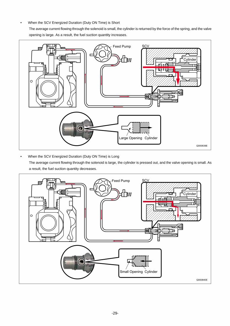
• When the SCV Energized Duration (Duty ON Time) is Short
The average current flowing through the solenoid is small, the cylinder is returned by the force of the spring, and the valve
opening is large. As a result, the fuel suction quantity increases.
• When the SCV Energized Duration (Duty ON Time) is Long
The average current flowing through the solenoid is large, the cylinder is pressed out, and the valve opening is small. As
a result, the fuel suction quantity decreases.
SCV
Cylinder
Feed Pump
Large Opening Cylinder
Q000839E
Small Opening Cylinder
SCV
Cylinder
Feed Pump
Q000840E
-29-

b) Normally Closed Type
• When the solenoid is energized, the cylinder is pressed by the armature, completely opening the fuel passage and sup-
plying fuel to the plunger portion. (Full quantity intake and full quantity discharge.)
• When the solenoid energizing ends, the return spring presses the cylinder and returns it, closing the fuel passage.
• The solenoid ON/OFF is actuated by duty ratio control. Fuel is supplied in an amount corresponding to the open surface
area of the passage, which depends on the duty ratio, and then is discharged by the plungers.
• Duty Ratio Control
The engine ECU outputs sawtooth wave signals with a constant frequency. The value of the current is the effective (av-
erage) value of these signals. As the effective value increases, the valve opening increases, and as the effective value
decreases, the valve opening decreases.
Q000841E
External ViewCross-Sectional
Return Spring Cylinder Solenoid
Valve BodyValve Needle
Q000844E
Average Current Difference
Actu
atin
g V
olta
ge
ON
OFF
Cu
rre
nt
High Suction Quantity Low Suction Quantity
-30-
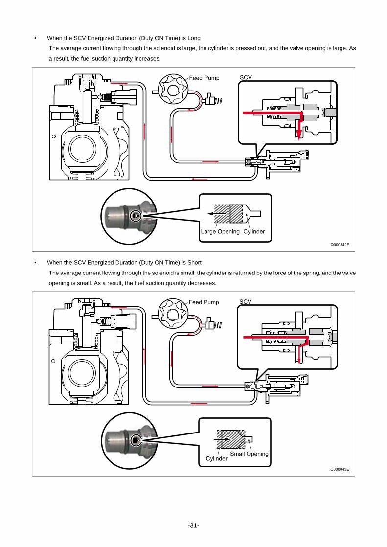
• When the SCV Energized Duration (Duty ON Time) is Long
The average current flowing through the solenoid is large, the cylinder is pressed out, and the valve opening is large. As
a result, the fuel suction quantity increases.
• When the SCV Energized Duration (Duty ON Time) is Short
The average current flowing through the solenoid is small, the cylinder is returned by the force of the spring, and the valve
opening is small. As a result, the fuel suction quantity decreases.
Large Opening Cylinder
SCVFeed Pump
Q000842E
SCVFeed Pump
Small OpeningCylinder
Q000843E
-31-

(4) Pump Unit (Eccentric Cam, Ring Cam, Plunger)
The eccentric cam is attached to the camshaft and the ring cam is installed on the eccentric cam. There are two plungers
at positions symmetrical above and below the ring cam.
• Because the rotation of the camshaft makes the eccentric cam rotate eccentrically, the ring cam follows this and moves
up and down, and this moves the two plungers reciprocally. (The ring cam itself does not rotate.)
Plunger ARing Cam
Feed Pump
Plunger B
Camshaft
Eccentric CamQ000845E
Q000846E
Ring Cam
Eccentric Cam
Camshaft
-32-

(5) Delivery Valve
The delivery valve for the HP3 has an integrated element and is made up of the check ball, spring, and holder. When the
pressure at the plunger exceeds the pressure in the rail, the check ball opens to discharge the fuel.
(6) Fuel Temperature Sensor
The fuel temperature sensor is installed on the fuel intake side and utilizes the characteristics of a thermistor in which
the electric resistance changes with the temperature in order to detect the fuel temperature.
ElementCheck Ball
Spring Holder
Plunger
Q000847E
Resistance - Temperature Characteristic
Temperature
Re
sis
tan
ce
Va
lue
Thermistor
Q000848E
-33-

d. Supply Pump Operation
(1) Supply Pump Overall Fuel Flow
The fuel is suctioned by the feed pump from the fuel tank and sent to the SCV. At this time, the regulating valve adjusts
the fuel pressure to below a certain level. The fuel sent from the feed pump has the required discharge quantity adjusted
by the SCV, and enters the pump unit through the suction valve. The fuel pumped by the pump unit is pumped through
the delivery valve to the rail.
Filter
From Pump
To Rail
Q000849E
Inject Rail
Discharge Valve Suction Valve
Plunger
Return Spring
Return
Combustion Overflow
Camshaft
Fuel Tank
Fuel Filter
(With Priming Pump)
Suction
Fuel Intake Port
Feed Pump
Regulating Valve
Suction Pressure
Feed Pressure
High Pressure
Return Pressure
-34-

(2) Operation
• The discharge quantity is controlled by SCV control, the same as for the HP2, however it differs from the HP2 in that the
valve opening is adjusted by duty ratio control.
• In the intake stroke, the spring makes the plunger follow the movement of the ring cam, so the plunger descends together
with the ring cam. Thus, unlike the HP2, the plunger itself also suctions in fuel. When the suctioned fuel passes through
the SCV, the flow quantity is controlled to the required discharge quantity by the valve opening and enters the pump main
unit.
• The quantity of fuel adjusted by the SCV is pumped during the pumping stroke.
SCV
Plunger B
Plunger AEccentric Cam
Delivery ValveSuction Valve
Ring Cam
Plunger A: End of Compression
Plunger B: End of Suction
Plunger A: End of Suction
Plunger B: End of Compression
Plunger B: Start of Compression
Plunger A: Start of Suction
Plunger B: Start of Suction
Plunger A: Start of Compression
QD0707E
-35-

D. HP4Typea. Construction and Characteristics
• The HP4 basic supply pump construction is the same as for the HP3 . The composition is also the same as the HP3,
being made up of the pump unit (eccentric cam, ring cam, plunger), the SCV (suction control valve), the fuel temperature
sensor, and the feed pump. The main difference is that there are three plungers.
• Because there are three plungers, they are positioned at intervals of 120° around the outside of the ring cam. In addition,
the fuel delivery capacity is 1.5 times that of the HP3.
• The fuel discharge quantity is controlled by the SCV, the same as for the HP3.
Q000850E
Suction Valve
Plunger
Eccentric Cam
SCV (Suction Control Valve)
Delivery Valve
Feed Pump
Fuel Temperature Sensor
-36-

b. Exploded View
Q000457E
SCV
Fuel Temperature Sensor
Filter
Feed Pump
Regulating Valve
Pump Body
Ring Cam
Camshaft
IN
OUT
-37-

c. Component Part Functions
The HP4 supply pump component parts and functions are basically the same as for the HP3. The explanations below
only cover those points on which the HP4 differs from the HP3. For other parts, see the appropriate item in the explana-
tion of the HP3.
(1) Pump Unit (Eccentric Cam, Ring Cam, Plunger)
• A triangular ring cam is installed on the eccentric cam on the drive shaft, and three plungers are installed to the ring cam
at intervals of 120°.
Component Parts Functions
Feed Pump Draws fuel from the fuel tank and feeds it to the plunger.
Regulating Valve Regulates the pressure of the fuel in the supply pump.
SCV (Suction Control Valve) Controls the quantity of fuel that is fed to the plungers.
Pump Unit
Eccentric Cam Actuates the ring cam.
Ring Cam Actuates the plunger.
Plunger Moves reciprocally to draw and compress fuel.
Suction Valve Prevents reverse flow of compressed fuel into the SCV.
Delivery Valve Prevents reverse flow from the rail of the fuel pumped from the plunger.
Fuel Temperature Sensor Detects the fuel temperature.
Ring Cam
Plunger
Camshaft
Eccentric Cam
Q000851E
-38-

• Because the rotation of the camshaft makes the eccentric cam rotate eccentrically, the ring cam follows this and this
moves the three plungers reciprocally. (The ring cam itself does not rotate.)
Plunger #1
Plunger #2
Eccentric CamCamshaft
Camshaft
Rotate 120 Clockwise
Camshaft
Rotate 120 Clockwise
Camshaft
Rotate 120 Clockwise
Ring Cam
Plunger #3
End of Pumping
End of Pumping
End of Pumping
Pumping
Pumping
Pumping
Suction
SuctionSuction
D000852E
-39-

d. Supply Pump Operation
(1) Supply Pump Overall Fuel Flow
The fuel is suctioned by the feed pump from the fuel tank and sent to the SCV. At this time, the regulating valve adjusts
the fuel pressure to below a certain level. The fuel sent from the feed pump has the required discharge quantity adjusted
by the SCV and enters the pump unit through the suction valve. The fuel pumped by the pump unit is pumped through
the delivery valve to the rail.
(2) Operation
The discharge quantity is controlled by the SCV. As with the HP3, the valve opening is adjusted by duty ratio control. The
only difference from the HP3 is the shape of the pump unit. Operation and control are basically the same. For details on
operation and control, see the explanation of the HP3.
Q000853E
Feed Pump from Fuel Tank (Suction)
SCV from Feed Pump (Low Pressure)
Pump Unit from SCV (Low-Pressure Adjustment Complete)
From Pump Unit to Rail (High Pressure)
From Fuel
Tank
To Rail
Plunger
Suction ValveDelivery Valve
Ring Cam
CamshaftSCV
Feed Pump
-40-

3-2. RAIL
A. Rail Functions and Composition• The function of the rail is to distribute fuel pressurized by the supply pump to each cylinder injector.
• The shape of the rail depends on the model and the component parts vary accordingly.
• The component parts are the rail pressure sensor (Pc sensor), pressure limiter, and for some models a flow damper and
pressure discharge valve.
B. Component Part Construction and Operation
Rail
Rail
Pressure Limiter
Pressure Limiter
Rail Pressure Sensor (Pc Sensor)
Rail Pressure Sensor (Pc Sensor)
Flow Damper
Pressure Discharge Valve
Q000854E
Component Parts Functions
Rail Stores pressurized fuel that has been pumped from the supply pump and distributes
the fuel to each cylinder injector.
Pressure Limiter Opens the valve to release pressure if the pressure in the rail becomes abnormally
high.
Rail Pressure Sensor (Pc Sensor) Detects the fuel pressure in the rail.
Flow Damper Reduces the pressure pulsations of fuel in the rail. If fuel flows out excessively, the
damper closes the fuel passage to prevent further flow of fuel. Mostly used with
engines for large vehicles.
Pressure Discharge Valve Controls the fuel pressure in the rail. Mostly used with engines for passenger cars.
-41-

a. Pressure Limiter
The pressure limiter opens to release the pressure if abnormally high pressure is generated. If pressure within the rail
becomes abnormally high, the pressure limiter operates (opens). It resumes operation (closes) after the pressure falls to
a certain level. Fuel released by the pressure limiter returns to the fuel tank.
< NOTE >• The operating pressures for the pressure limiter depend on the vehicle model and are approximately 140-230MPa for
the valve opening pressure, and approximately 30-50MPa for the valve closing pressure.
b. Rail Pressure Sensor (Pc Sensor)
The rail pressure sensor (Pc sensor) is installed on the rail. It detects the fuel pressure in the rail and sends a signal to
the engine ECU. This is a semi-conductor sensor that uses the piezo-electric effect of the electrical resistance varying
when pressure is applied to a silicon element.
• There are also rail pressure sensors that have dual systems to provide a backup in case of breakdown. The output volt-
age is offset.
Pressure Limiter
Leak
(To Fuel Tank)
Valve Open
Valve Close
Rail Pressure
Abnormally High Pressure
Return
Q000855E
GND
Vout
Sensor Wiring Diagram Common Rail Pressure Characteristic
Output Voltage
-
Rail Pressure
Ou
tpu
t V
olta
ge
Vcc+5V
ECUPc
Vout Vcc=5V
GND Vout Vcc
Q000856E
Q000857E
E2S PR2 VCS
VC PR E2
PcSensors
VCVCS
PR2PR
E2E2S
+5V
ECU
ECU
Vout/VccVcc=5V
Rail Pressure
Outp
ut V
olta
ge 1
Outp
ut V
olta
ge 2
-42-

c. Flow Damper
The flow damper reduces the pressure pulsations of the fuel in the pressurized pipe and supplies fuel to the injectors at
a stabilized pressure. The flow damper also presents abnormal discharge of fuel by shutting off the fuel passage in the
event of excess fuel discharge, for example due to fuel leaking from an injection pipe or injector. Some flow dampers
combine a piston and ball, and some have only a piston.
(1) Operation of Piston-and-Ball Type
When a pressure pulse occurs in a high-pressure pipe, the resistance of it passing through the orifice disrupts the bal-
ance between the rail side and injector side pressures, so the piston and ball move to the injector side, absorbing the
pressure pulse. With normal pressure pulses, since the rail side and injector side pressures are soon balanced, the piston
and ball are pushed back to the rail side by the spring. If there is an abnormal discharge, for example due to an injector
side fuel leak, the amount of fuel passing through the orifice cannot be balanced out and the piston presses the ball
against the seat, so the passage for fuel to the injector is shut off.
(2) Operation of Piston-Only Type
The piston contacts the seat directly and the piston shuts off the fuel passage directly. Operation is the same as for the
piston-and-ball type.
Q000858E
Piston Ball
Seat Spring
Piston
Spring
Seat
Type Combining Piston and Ball Piston-Only Type
Q000859E
· During Pressure Pulse Absorption · Fuel Cut-Off
Piston Ball
SeatSpring
Q000860E
· During Pressure Pulse Absorption · Fuel Cut-Off
Piston
Spring
Seat
-43-

d. Pressure Discharge Valve
The pressure discharge valve controls the fuel pressure in the rail. When rail fuel pressure exceeds the target injection
pressure, or when the engine ECU judges that rail fuel pressure exceeds the target value, the pressure discharge valve
solenoid coil is energized. This opens the pressure discharge valve passage, allowing fuel to leak back to the fuel tank,
and reducing rail fuel pressure to the target pressure.
Q000861E
Pressure Discharge Valve
Rail
ON
ECU
To Fuel tank
Operating
Solenoid Coil
-44-

3-3. INJECTOR
A. General Description• The injector injects the pressurized fuel in the rail into the engine combustion chamber at the optimal injection timing,
injection quantity, injection rate, and injection pattern, in accordance with signals from the ECU.
• Injection is controlled using a TWV (Two-Way Valve) and orifice. The TWV controls the pressure in the control chamber
to control the start and end of injection. The orifice controls the injection rate by restraining the speed at which the nozzle
opens.
• The command piston opens and closes the valve by transmitting the control chamber pressure to the nozzle needle.
• When the nozzle needle valve is open, the nozzle atomizes the fuel and injects it.
• There are three types of injectors: the X1, X2, and G2.
Q000862E
ECU
Supply Pump
Nozzle
Command Piston
Control Chamber Portion
Orifice
TWV
Rail
Rail Pressure Sensor
Nozzle Needle
-45-

B. Injector Construction and FeaturesThe injector consists of a nozzle similar to the conventional "nozzle & nozzle holder", an orifice that controls the injection
rate, the command piston, and a TWV (two-way solenoid valve). The basic construction is the same for the X1, X2, and
G2 types.
a. X1 Type
Precision control is attained through electronic control of the injection. The TWV comprises two valves: the inner valve
(fixed) and the outer valve (movable).
Q000863E
Nozzle
Command Piston
TWV
Solenoid
Orifice 1 Orifice 2
Inner Valve
Outer Valve
-46-

b. X2 Type
By reducing the injector actuation load, the injector has been made more compact and energy efficient, and its injection
precision has been improved. The TWV directly opens and closes the outlet orifice.
Control
ChamberSolenoid
ValveHollow Screw with Damper
O-ring
Command Piston
Nozzle Spring
Pressure Pin
Nozzle Needle
Seat
High-Pressure FuelLeak Passage
From Rail
Q000864E
-47-

c. G2 Type
To ensure high pressure, the G2 type has improved pressure strength, sealing performance and pressure wear resis-
tance. It also has improved high-speed operability, enabling higher-precision injection control and multi-injection.
< NOTE >• Multi-injection means that for the purpose of reducing exhaust gas emissions and noise, the main injection is accom-
plished with one to five injections of fuel without changing the injection quantity.
Q000865E
Connector
Solenoid Valve
Command Piston
Nozzle Spring
Pressure Pin
Nozzle Needle
Seat Leak Passage
From Rail
To Fuel Tank
Example : Pattern with Five Injections
Time
Pre-InjectionPilot Injection After-Injection
Main Injection
Post-Injection
Inje
ctio
n Q
ua
ntity
Q000866E
-48-

C. Injector OperationThe injector controls injection through the fuel pressure in the control chamber. The TWV executes leak control of the
fuel in the control chamber to control the fuel pressure within the control chamber. The TWV varies with the injector type.
a. Non-Injection
When the TWV is not energized, the TWV shuts off the leak passage from the control chamber, so the fuel pressure in
the control chamber and the fuel pressure applied to the nozzle needle are both the same rail pressure. The nozzle nee-
dle thus closes due to the difference between the pressure-bearing surface area of the command piston and the force of
the nozzle spring, and fuel is not injected. For the X1 type, the leak passage from the control chamber is shut off by the
outer valve being pressed against the seat by the force of the spring, and the fuel pressure within the outer valve. For
the X2/G2 types, the control chamber outlet orifice is closed directly by the force of the spring.
b. Injection
When TWV energization starts, the TWV valve is pulled up, opening the leak passage from the control chamber. When
this leak passage opens, the fuel in the control chamber leaks out and the pressure drops. Because of the drop in pres-
sure within the control chamber, the pressure on the nozzle needle overcomes the force pressing down, the nozzle nee-
dle is pushed up, and injection starts. When fuel leaks from the control chamber, the flow quantity is restricted by the
orifice, so the nozzle opens gradually. The injection rate rises as the nozzle opens. As current continues to be applied to
the TWV, the nozzle needle eventually reaches the maximum amount of lift, which results in the maximum injection rate.
Excess fuel is returned to the fuel tank through the path shown.
c. End of Injection
When TWV energization ends, the valve descends, closing the leak passage from the control chamber. When the leak
passage closes, the fuel pressure within the control chamber instantly returns to the rail pressure, the nozzle closes sud-
denly, and injection stops.
Q000867E
Outer Valve
Injection Rate
Control Chamber Pressure
Control Chamber Pressure
Control Chamber Pressure
Solenoid
TWV
Outlet Orifice
Inlet Orifice
Command Piston
NozzleInjection Rate Injection Rate
Non-Injection Injection End of Injection
Rail
X1
X2 · G2
Outlet Orifice
Actuating Current
Actuating Current
Actuating Current
Inner Valve
To Fuel TankLeak Passage
Leak Passage
TWV
-49-

D. Injector Actuation CircuitIn order to improve injector responsiveness, the actuation voltage has been changed to high voltage, speeding up both
solenoid magnetization and the response of the TWV. The EDU or the charge circuit in the ECU raises the respective
battery voltage to approximately 110V, which is supplied to the injector by signal from the ECU to actuate the injector.
Q000868E
INJ#1 (No.1 Cylinder)
ECU
Injector
INJ#2 (No.3 Cylinder)
INJ#3 (No.4 Cylinder)
INJ#4 (No.2 Cylinder)
Charging Circuit
IJt
IJf
EDU
Actuating Current
ECU
Actuating Current
ECU Direct Actuation
EDU Actuation
2WV#3 (No.3 Cylinder)
2WV#4 (No.6 Cylinder)
2WV#5 (No.2 Cylinder)
2WV#6 (No.4 Cylinder)
Injector
Common 2
Common 1
2WV#1 (No.1 Cylinder)
2WV#2 (No.5 Cylinder)
Constant Amperage Circuit
High Voltage
Generation Circuit
Control
Circuit
Constant Amperage Circuit
Constant Amperage Circuit
High Voltage Generation Circuit
-50-

E. Other Injector Component Partsa. Hollow Screw with Damper
The hollow screw with damper enhances injection quantity accuracy, by reducing the back-pressure pulsations (pressure
fluctuations) of the leak fuel. In addition, it minimizes the back-pressure dependence (the effect of the pressure in the
leak pipe changing the injection quantity even though the injection command is the same) of the fuel in the leak pipe.
b. Connector with Correction Resistor
The connector with correction resistor has a built-in correction resistor in the connector section to minimize injection
quantity variation among the cylinders.
c. Injector with QR Codes
QR (Quick Response) codes have been adopted to enhance correction precision. The QR code, which contains the cor-
rection data of the injector, is written to the engine ECU. QR codes have resulted in a substantial increase in the number
of fuel injection quantity correction points, greatly improving injection quantity precision.
< NOTE >• QR codes are a new two-dimensional code that was developed by DENSO. In addition to injection quantity correction
data, the code contains the part number and the product number, which can be read at extremely high speeds.
Q000869E
Hollow Screw with Damper
O-ring
O-ring
Damper
To Fuel tank
Q000870E
Correction Resistor Terminal
Solenoid Terminal
Q000871E
Inje
ctio
n Q
ua
ntity
Actuating Pulse Width TQ
Pressure Parameter
· QR Code Correction Points (Example)
10EA01EB13EA01EB
0300 00000000 BC
QR Codes
ID Codes
-51-

(1) Handling Injectors with QR Codes (Reference)
Injectors with QR codes have the engine ECU recognize and correct the injectors, so when an injector or the engine ECU
is replaced, it is necessary to register the injector's ID code in the engine ECU.
A) Replacing the Injector
It is necessary to register the ID code of the injector that has been replaced in the engine ECU.
B) Replacing the Engine ECU
It is necessary to register the ID codes of all the vehicle injectors in the engine ECU.
QD1536E
Engine ECU
Spare Injector
"No correction resistance, so no electrical recognition capability."
* Necessary to record the injector ID codes in the Engine ECU.
"No correction resistance, so no electrical recognition capability."
* Necessary to record the injector ID codes in the Engine ECU.
Q000985E
Vehicle-Side Injector Spare Engine ECU
-52-

4. DESCRIPTION OF CONTROL SYSTEM COMPONENTS
4-1. ENGINE CONTROL SYSTEM DIAGRAM (REFERENCE)
Q000874E
Rail
Rail Pressure Sensor
Pressure Discharge Valve
Pressure Limiter
Injector
Engine ECU
EDU
E-VRV for EGR
EGR Shut-Off VSV
Crankshaft Position Sensor (Engine Speed Sensor)
Cylinder Recognition Sensor (TDC (G) Sensor: HP2, 3, 4)
Accelerator Position Sensor
Intake Air Temperature SensorAirflow Meter
(with Intake Air Temperature Sensor)
Coolant Temperature Sensor
Intake Air Pressure Sensor
Ignition Switch Signal
Starter Signal
Warm-Up Switch Signal
Vehicle Speed Signal
Supply Pump
TDC(G) Sensor(HP0)
SCV(HP2·3·4)
Fuel Temperature Sensor (HP2·3·4)
PCV(HP0)
To Fuel Tank
Charge Circuit
Flow Damper (Large Vehicles)
PCV TDC (G) Sensor
Fuel Temperature Sensor
SCV
Fuel Temperature Sensor
Fuel Temperature Sensor
SCV
SCV
Supply Pump
HP0 HP2 HP3 HP4
Fuel Temperature Sensor (HP0)
Flywheel
-53-

4-2. ENGINE ECU (ELECTRONIC CONTROL UNIT)• The engine ECU constantly ascertains the status of the engine through signals from the sensors, calculates fuel injection
quantities etc. appropriate to the conditions, actuates the actuators, and controls to keep the engine in an optimal state.
The injectors are actuated by either the EDU or the charge circuit in the engine ECU. This actuation circuit depends on
the specifications of the model it is mounted in. The ECU also has a diagnosis function for recording system troubles.
4-3. EDU (ELECTRONIC DRIVING UNIT)
A. General DescriptionAn EDU is provided to enable high-speed actuation of the injectors. The EDU has a high-voltage generation device (DC/
DC converter) and supplies high voltage to the injectors to actuate the injectors at high speed.
Q000875E
Sensors Engine ECU Actuators
Cylinder Recognition Sensor
(TDC (G) Sensor)
Crankshaft Position Sensor
(Engine Speed Sensor)
Accelerator Position Sensor
Other Sensors
Engine ECU
Injector
Supply Pump
(PCV : HP0, SCV : HP2 · HP3 · HP4)
Other Actuators
Charge Circuit (Built into ECU)
or
EDU
Actuation Circuit
ECU EDU
Actuation Signal
Check Signal
Actuation Output
Q000876E
-54-
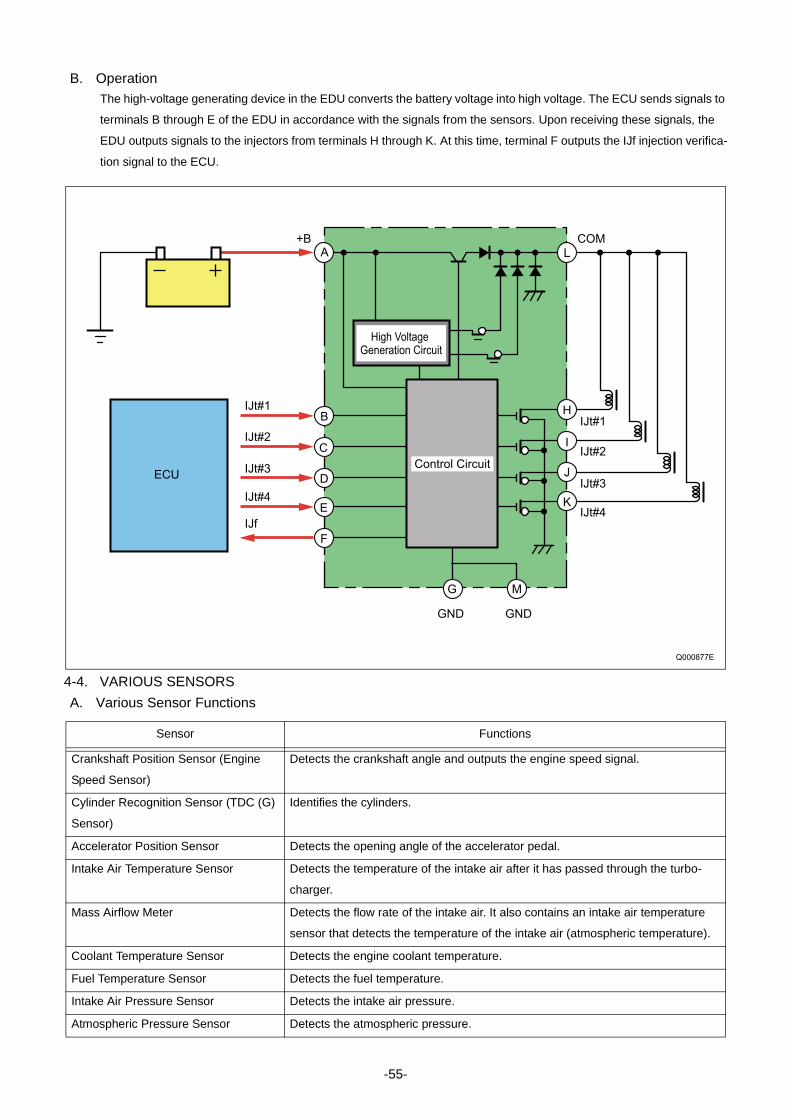
B. OperationThe high-voltage generating device in the EDU converts the battery voltage into high voltage. The ECU sends signals to
terminals B through E of the EDU in accordance with the signals from the sensors. Upon receiving these signals, the
EDU outputs signals to the injectors from terminals H through K. At this time, terminal F outputs the IJf injection verifica-
tion signal to the ECU.
4-4. VARIOUS SENSORS
A. Various Sensor Functions
GND GND
High Voltage Generation Circuit
Control Circuit
A L
BIJt#1
IJt#1
COM+B
IJt#2
IJt#3
IJt#4
IJt#2
IJt#3
IJt#4
IJf
C
D
E
F
G M
H
I
J
K
ECU
Q000877E
Sensor Functions
Crankshaft Position Sensor (Engine
Speed Sensor)
Detects the crankshaft angle and outputs the engine speed signal.
Cylinder Recognition Sensor (TDC (G)
Sensor)
Identifies the cylinders.
Accelerator Position Sensor Detects the opening angle of the accelerator pedal.
Intake Air Temperature Sensor Detects the temperature of the intake air after it has passed through the turbo-
charger.
Mass Airflow Meter Detects the flow rate of the intake air. It also contains an intake air temperature
sensor that detects the temperature of the intake air (atmospheric temperature).
Coolant Temperature Sensor Detects the engine coolant temperature.
Fuel Temperature Sensor Detects the fuel temperature.
Intake Air Pressure Sensor Detects the intake air pressure.
Atmospheric Pressure Sensor Detects the atmospheric pressure.
-55-

d. Crankshaft Position Sensor (Engine Speed Sensor) and Cylinder Recognition Sensor (TDC (G) Sensor)
(1) Crankshaft Position Sensor (Engine Speed Sensor)
The crankshaft position sensor is installed near the crankshaft timing gear or the flywheel. The sensor unit is a MPU
(magnetic pickup) type. When the engine speed pulsar gear installed on the crankshaft passes the sensor section, the
magnetic field of the coil within the sensor changes, generating AC voltage. This AC voltage is detected by the engine
ECU as the detection signal. The number of pulses for the engine speed pulsar depends on the specifications of the
vehicle the sensor is mounted in.
(2) Cylinder Recognition Sensor (TDC (G) Sensor)
The cylinder recognition sensor is installed on the supply pump unit for the HP0 system, but for the HP2, HP3, or HP4
system, it is installed near the supply pump timing gear. Sensor unit construction consists of the MPU type, which is the
same as for the crankshaft position sensor, and the MRE (magnetic resistance element) type. For the MRE type, when
the pulsar passes the sensor, the magnetic resistance changes and the voltage passing through the sensor changes.
This change in voltage is amplified by the internal IC circuit and output to the engine ECU. The number of pulses for the
TDC pulsar depends on the specifications of the vehicle the sensor is mounted in.
Sensor Mounting Position (Reference)
NE+
NE-
VCC
TDC(G)
GND
TDC(G)TDC(G)-TDC(G)GNDVCC
NE
TDC (G) Pulse
TDC(G)
ECU
0V
360 CA 360 CA
720 CA
Engine Speed Pulsar TDC (G) Pulsar
Q000878E
Pulsar (Gearless Section)
Crankshaft Position Sensor (Engine Speed Sensor)
Cylinder Recognition Sensor (TDC (G) Sensor)
Pulsar
For MPU Type
For MRE Type
MPU Type
MPUType
MRE Type
MRE Type
MPUType
MRE Type
External View of Sensor
ShieldedWire
Crankshaft Position Sensor (Engine Speed Sensor)
Cylinder Recognition Sensor(TDC (G) Sensor)
TDC (G) Input Circuit
Engine SpeedInput Circuit
Circuit Diagram
Pulse Chart (Reference)
Engine Speed
Pulse
-56-
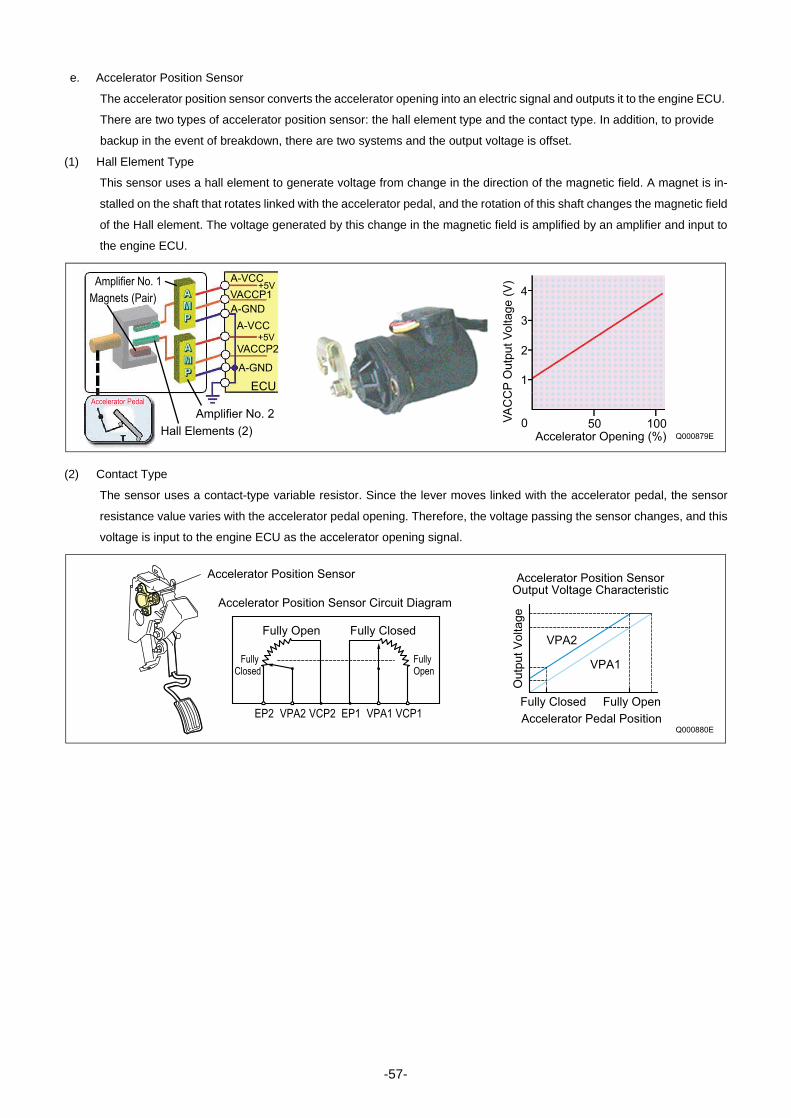
e. Accelerator Position Sensor
The accelerator position sensor converts the accelerator opening into an electric signal and outputs it to the engine ECU.
There are two types of accelerator position sensor: the hall element type and the contact type. In addition, to provide
backup in the event of breakdown, there are two systems and the output voltage is offset.
(1) Hall Element Type
This sensor uses a hall element to generate voltage from change in the direction of the magnetic field. A magnet is in-
stalled on the shaft that rotates linked with the accelerator pedal, and the rotation of this shaft changes the magnetic field
of the Hall element. The voltage generated by this change in the magnetic field is amplified by an amplifier and input to
the engine ECU.
(2) Contact Type
The sensor uses a contact-type variable resistor. Since the lever moves linked with the accelerator pedal, the sensor
resistance value varies with the accelerator pedal opening. Therefore, the voltage passing the sensor changes, and this
voltage is input to the engine ECU as the accelerator opening signal.
Q000879E
4
3
2
1
0 50 100VA
CC
P O
utp
ut
Vo
lta
ge
(V
)
Accelerator Opening (%)Hall Elements (2)
Magnets (Pair)
Amplifier No. 1
Amplifier No. 2
+5V
+5V
A-VCC
A-VCC
VACCP1
VACCP2
A-GND
A-GND
ECUAccelerator Pedal Accelerator Pedal
VPA2
VPA1
EP2 VPA2 VCP2 EP1 VPA1 VCP1
Accelerator Position Sensor Circuit Diagram
Ou
tpu
t V
olta
ge
Accelerator Pedal Position
Accelerator Position Sensor
Fully Open
Fully Open
FullyOpen
Q000880E
Fully Closed
Fully Closed
Fully Closed
Accelerator Position SensorOutput Voltage Characteristic
-57-

f. Intake Air Temperature Sensor
The intake air temperature sensor detects the temperature of the intake air after it has passed the turbocharger. The
sensor portion that detects the temperature contains a thermistor. The thermistor, which has an electrical resistance that
changes with temperature, is used to detect the intake air temperature.
g. Mass Airflow Meter (with Built-In Intake Air Temperature Sensor)
The mass air flow meter is installed behind the air cleaner and detects the intake air flow (mass flow). This sensor is a
hot-wire type. Since the electrical resistance of the hot wire varies with the temperature, this characteristic is utilized to
measure the intake air quantity. The mass airflow meter also has a built-in intake air temperature sensor (thermistor type)
and detects the intake air temperature (atmospheric temperature).
h. Coolant Temperature Sensor
The coolant temperature sensor is installed on the cylinder block and detects the coolant temperature. This sensor is a
thermistor type.
Thermistor
Q000881E
Re
sis
tan
ce
Temperature
Resistance - TemperatureCharacteristic
E2THAFVGE2G+B
Temperature
Temperature Characteristic
C ( F)
Intake Air TemperatureSensor
Hot Wire
Q000882E
Re
sis
tan
ce
Intake Air Temperature Sensor Resistance
-
Q000883E
Coolant Temperature
Re
sis
tan
ce
Va
lue+5V
VTHW
A-GND
ECU
Thermistor
Coolant TemperatureSensor Resistance
Water TemperatureCharacteristic
-
-58-

i. Fuel Temperature Sensor
This is a thermistor type sensor that detects the fuel temperature. In the HP2, HP3, and HP4 systems, this sensor is
installed on the supply pump unit, but in the HP0 system, it is installed on a leak pipe from an injector.
j. Intake Air Temperature Sensor and Atmospheric Pressure Sensor
This sensor is a semiconductor type sensor. It measures pressure utilizing the piezoelectric effect that when the pressure
on the silicon element in the sensor changes, its electrical resistance changes. In addition, the air pressure on this sensor
is switched between the pressure within the intake manifold and the atmospheric pressure, so both the intake air pres-
sure and the atmospheric pressure are detected with one sensor. The switching between intake air pressure and atmo-
spheric pressure is handled by the VSV (vacuum switching valve). When any one of the conditions below is established,
the VSV is switched ON for 150 msec. by command of the engine ECU to detect the atmospheric pressure. When none
of the conditions below is established, the VSV is switched OFF to detect the intake air pressure.
(1) Atmospheric Pressure Measurement Conditions
• Engine speed = 0 rpm
• Starter ON
• Stable idling state
Q000848E
TemperatureCharacteristic
Temperature
Re
sis
tan
ce
Va
lue
Thermistor +5V
VTHL
A-GND
Engine ECUResistance -
Q000885E
VC PIM E2
Absolute Pressure
PIM Output Voltage - Pressure
Characteristic
Ou
tpu
t V
olta
ge
-59-

5. CONTROL SYSTEMS
5-1. FUEL INJECTION CONTROL
A. General DescriptionThis system effects more appropriate control of the fuel injection quantity and injection timing than the mechanical gov-
ernor or timer used in the conventional injection pump. The engine ECU performs the necessary calculations based on
the signals that are received from the sensors located on the engine and the vehicle. Then, the ECU controls the timing
and duration of the current that is applied to the injectors in order to obtain optimal injection timing and injection quantity.
B. Various Types of Fuel Injection Controls
Control Functions
Fuel Injection Quantity Control This control replaces the function of the governor in the conventional injection
pump. It achieves optimal injection quantity by effecting control in accordance with
the engine speed and accelerator opening signals.
Fuel Injection Timing Control This control replaces the function of the timer in the conventional injection pump. It
achieves optimal injection timing by effecting control in accordance with the
engine speed and the injection quantity.
Fuel Injection Rate Control (Pilot Injec-
tion Control)
This function controls the ratio of the fuel quantity that is injected from the orifice of
the injector within a given unit of time.
Fuel Injection Pressure Control This control uses the rail pressure sensor to measure the fuel pressure, and it
feeds this data to the engine ECU in order to control the pump discharge quantity.
-60-

C. Fuel Injection Quantity Controla. General Description
This control determines the fuel injection quantity by adding coolant temperature, fuel temperature, intake air tempera-
ture, and intake air pressure corrections to the basic injection quantity. The engine ECU calculates the basic injection
quantity based on the engine operating conditions and driving conditions.
b. Injection Quantity Calculation Method
The calculation consists of a comparison of the following two values: 1. The basic injection quantity that is obtained from
the governor pattern, which is calculated from the accelerator position and the engine speed. 2. The injection quantity
obtained by adding various types of corrections to the maximum injection quantity obtained from the engine speed. The
lesser of the two injection quantities is used as the basis for the final injection quantity.
Q000887E
Engine Speed
Engine Speed
Accelerator Opening
Inje
ctio
n
Qu
an
tity
Inje
ctio
n
Qu
an
tity
Accelerator Opening
Engine Speed
Basic Injection Quantity
Maximum Injection Quantity
Low Quantity
Side Selected
Corrected Final Injection
Quantity
Injector Actuation
Period Calculation
Individual Cylinder Correction Quantity
Intake Air Pressure Correction
Atmospheric Pressure Correction
Cold Engine Maximum Injection Quantity Correction
Ambient Temperature Correction
Intake Air Temperature Correction
Speed Correction
Injection Pressure Correction
-61-

c. Set Injection Quantities
(1) Basic Injection Quantity
This quantity is determined by the engine speed and the
accelerator opening. With the engine speed constant, if the
accelerator opening increases, the injection quantity in-
creases; with the accelerator opening constant, if the en-
gine speed rises, the injection quantity decreases.
(2) Starting Injection Quantity
This is determined based on the basic injection quantity for
when the engine starts up and the added corrections for
the starter S/W ON time, the engine speed, and the coolant
temperature. If the coolant temperature is low, the injection
quantity is increased. When the engine has completely
started up, this mode is cancelled.
(3) Injection Quantity for Maximum Speed Setting
Determined by the engine speed. The injection quantity is
restricted to prevent an excessive rise in engine speed
(overrun).
(4) Maximum Injection Quantity
This is determined based on the basic maximum injection
quantity determined by the engine speed, and the added
corrections for coolant temperature, fuel temperature, in-
take air temperature, atmospheric temperature, intake air
pressure, atmospheric pressure, and full Q adjustment re-
sistance (only for the 1st generation HP0 system), etc.
Ba
sic
In
jectio
n Q
ua
ntity
Engine Speed
Accelerator Opening
Q000888E
Inje
ctio
n Q
ua
ntity
STA ON Time
STA ON Starting
Starting Base InjectionQuantity
Coolant Temperature
High Low
Q000889E
Inje
ctio
n Q
ua
ntity
Engine Speed
Injection Quantity
for Maximum Speed Setting
Q000890E
QB0717E
Engine Speed
Ba
sic
Ma
xim
um
In
jectio
n Q
ua
ntity
-62-

d. Corrections
(1) Cold Engine Maximum Injection Quantity Correction
When the coolant temperature is low, whether during start-
up or during normal operation, this correction increases the
injection quantity.
(2) Intake Air Pressure Correction
When the intake air pressure is low, the maximum injection
quantity is restricted in order to reduce the emission of
black smoke.
(3) Atmospheric Pressure Correction
The maximum injection quantity is increased and de-
creased according to the atmospheric pressure. When the
atmospheric pressure is high, the maximum injection quan-
tity is increased.
(4) Injection Quantity Delay Correction for Acceleration
During acceleration, if there is a large change in the accel-
erator pedal opening, the injection quantity increase is de-
layed in order to prevent black smoke emissions.
Inje
ctio
n Q
ua
ntity
Engine SpeedQ000891E
Q000892E
Engine Speed
Intake Air Pressure Correction Quantity
Inje
ctio
n Q
ua
ntity
Q000893E
Engine Speed
Atmospheric PressureCorrection Quantity
Inje
ctio
n Q
ua
ntity
Q000487E
Time
Change in Accelerator Pedal Position
Injection QuantityAfter Correction
Delay
Inje
ctio
n Q
ua
ntity
-63-

(5) Full Q Adjustment Resistance (Only for 1st Generation HP0 Systems)
The full Q resistance is for correcting the injection quantity for a full load. The maximum injection quantity is increased or
decreased by the car manufacturer to match to standards. There are 15 types of full Q adjustment resistance. The ap-
propriate one is selected and used.
D. Fuel Injection Rate Controla. General Description
Although the injection rate increases with the adoption of high-pressure fuel injection, the ignition lag, which is the delay
from the start of injection to the beginning of combustion, cannot be shortened to less than a certain period of time. There-
fore, the quantity of fuel injected until ignition takes place increases (the initial injection rate is too high), resulting in ex-
plosive combustion simultaneous with ignition, and an increase in NOx and sound. To counteract this situation, pilot
injection is provided to keep the initial injection at the minimum requirement rate, to dampen the primary explosive com-
bustion, and to reduce NOx and noise.
< NOTE >• For an image of the inside of the combustion chamber, there is a sample map of the basic pilot injection quantity in the
material at the end of this document.
+5V
ECU
VLQC
A-GND
Quantity Adjustment Resistor Correction Voltage
Q000894E
Quantit
y A
dju
stm
ent
Corr
ect
ion Inje
ctio
n Q
uantit
y
Q000895E
Injection Rate
Heat Release Rate
Large First-StageCombustion
Small First-StageCombustion
Crankshaft Angle (deg) Crankshaft Angle (deg)
-20 TDC 20 40 -20 TDC 20 40
[Ordinary Injection] [Pilot Injection]
-64-

E. Fuel Injection Timing Controla. General Description
The fuel injection timing is controlled by the timing of the current applied to the injectors. After the main injection period
is decided, the pilot injection and other injection timing is determined.
b. Main and Pilot Injection Timing Control
(1) Main Injection Timing
The basic injection timing is calculated from the engine speed (engine speed pulse) and the final injection quantity, to
which various types of corrections are added in order to determine the optimal main injection timing.
(2) Pilot Injection Timing (Pilot Interval)
Pilot injection timing is controlled by adding a pilot interval value to the main injection. The pilot interval is calculated
based on the final injection quantity, engine speed, coolant temperature, atmospheric temperature, and atmospheric
pressure (map correction). The pilot interval at the time the engine is started is calculated from the coolant temperature
and engine speed.
Q000896E
Actual Top Dead Center
Pilot Injection Main Injection
Pilot Injection Timing
Pilot Interval
Main Injection Timing
1. Outline of Injection Timing Control Timing
2. Injection Timing Calculation Method
Engine Speed
Injection Quantity
Basic InjectionTiming
Correction
Main Injection Timing
Battery Voltage Correction
Intake Air Pressure Correction
Atmospheric Pressure Correction
Intake Air Temperature Correction
Coolant Temperature Correction
Pilot Interval Basic InjectionTiming
Pilo
t In
terv
al
Engine Speed
Ba
sic
Inje
ctio
n T
imin
g
PilotInjection Timing
NE
INJ
lift
10
Engine Speed
Engine Speed Pulse
Injector Solenoid ValveControl Pulse
Nozzle NeedleLift
-65-

(3) Split Injection
The purpose of split injection is to improve the startability of a cold engine. Before the conventional main injection takes
place, this function injects two or more extremely small injections of fuel.
(4) Multi-Injection Control (Only for Some Models)
Multi-injection control is when small injections (up to four times) are carried out before and after the main injection in ac-
cordance with the state of the main injection and engine operation. This interval (the time A-D in the diagram below) is
based on the final injection quantity, engine speed, coolant temperature, and atmospheric pressure (map correction).
The interval during start-up is based on the coolant temperature and engine speed.
F. Fuel Injection Pressure ControlThe engine ECU calculates the fuel injection pressure, which is determined by the final injection quantity and the engine
speed. The calculation is based on the coolant temperature and engine speed during start-up.
Q000897E
Main Injection Main Injection
Pilot Injection
Pilot Injection
Pilot Injection
Multi-Injection
This is the same as conventional
fuel injection.
Before the main injection, a small
quantity of fuel is injected.
If the temperature is low when the engine
starts, a small quantity of fuel is injected
divided over multiple injections before the
main injection.
Pre-Injection
Q000898E
TDC
A C DB
TDC (G) Pulse
Injection Rate
Q000899EEngine Speed
Final Injection Quantity
Ra
il P
ressu
re
-66-

G. Other Injection Quantity Controla. Idle Speed Control (ISC) System
The idle speed control system controls the idle speed by regulating the injection quantity in order to match the actual
speed to the target speed calculated by the computer. The ISC can be automatic ISC or manual ISC.
(1) Automatic ISC
With automatic ISC, the engine ECU sets the target speed. The target engine speed varies with the type of transmission
(automatic or manual), whether the air conditioner is ON or OFF, the shift position, and the coolant temperature.
(2) Manual ISC
The idle engine speed is controlled by the setting on the idle setting button at the driver's seat.
Idle Speed Control Conditions
Conditions When Control Starts Conditions Affecting Control
· Idle Switch
· Accelerator Opening
· Vehicle Speed
· Water Temperature
· Air Conditioning Load
· Shift Position
Engine ECU
Target Engine Speed Calculation Comparison
Fuel injection Quantity Correction
Actual Engine Speed
ActuatorsFuel Injection Quantity Instruction
Q000900E
ECU
A-GND
V-IMC
A-VCC+5V
IMC Volume Terminal Voltage
Q000901E
Ta
rge
t E
ng
ine
Sp
ee
d
-67-
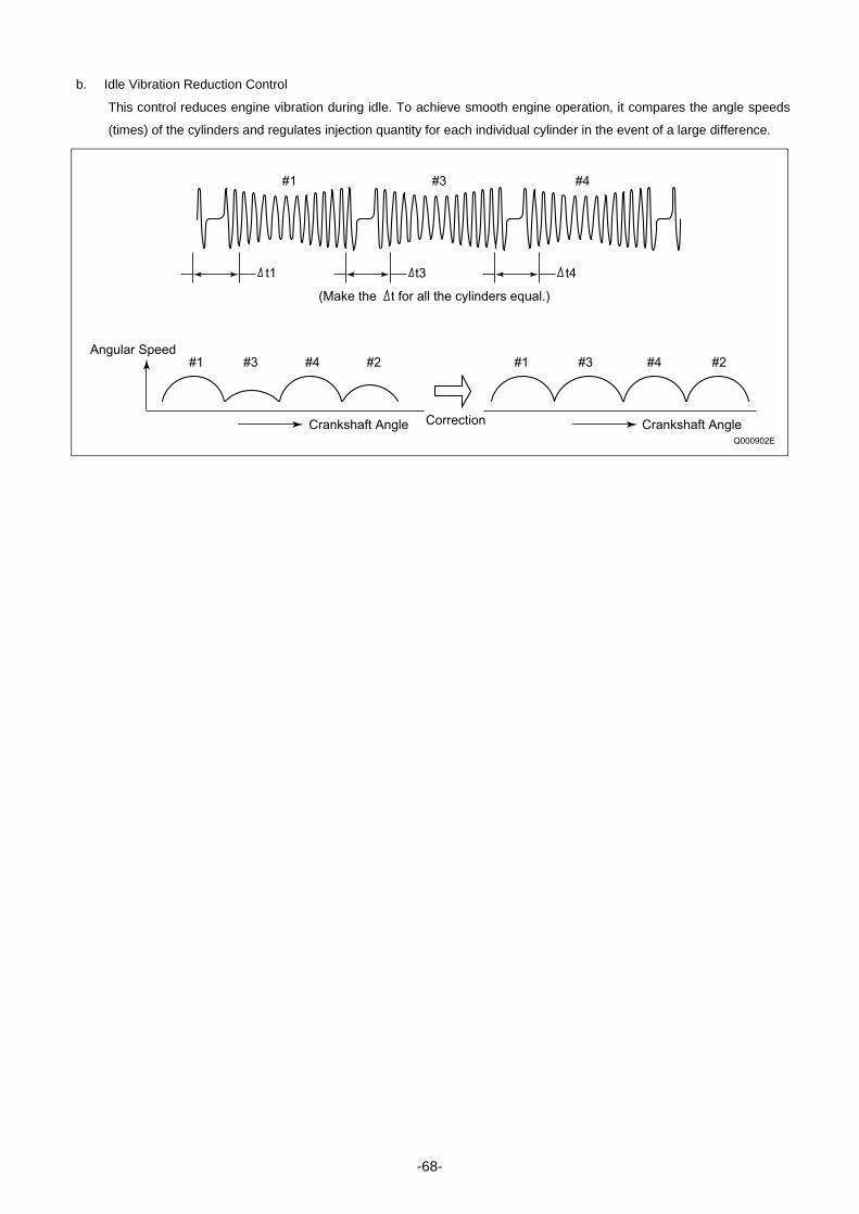
b. Idle Vibration Reduction Control
This control reduces engine vibration during idle. To achieve smooth engine operation, it compares the angle speeds
(times) of the cylinders and regulates injection quantity for each individual cylinder in the event of a large difference.
Q000902E
t4 t3 t1
#1 #3 #4
#1 #1 #3 #4 #2#3 #4 #2
(Make the t for all the cylinders equal.)
Angular Speed
Crankshaft Angle Crankshaft AngleCorrection
-68-

5-2. E-EGR SYSTEM (ELECTRIC-EXHAUST GAS RECIRCULATION)
A. General DescriptionThe E-EGR system is an electronically controlled EGR system. The EGR system recirculates a portion of the exhaust
gases into the intake manifold in order to lower the combustion chamber temperature and reduce NOx emissions. How-
ever, operation of the EGR system may reduce engine power output and affect drivability. For this reason, in the E-EGR
system, the engine ECU controls the EGR to achieve an optimal EGR amount.
a. Operation Conditions Example
This operates in the operation region fulfilling the starting conditions below (one example).
B. Operation• After the vacuum pump generates a vacuum, the E-VRV (electric-vacuum regulation valve) regulates the vacuum and
directs it to the diaphragm chamber of the EGR valve. In response to this vacuum, the diaphragm pushes the spring
downward, which determines the opening of the EGR valve and controls the EGR volume.
• The EGR cooler, which is provided in the EGR passage between the cylinder head and the intake passage, cools the
EGR in order to increase the EGR volume.
• The EGR cutoff VSV, which opens the diaphragm chamber to the atmosphere when the EGR valve is closed, helps to
improve response.
Inje
ctio
n Q
ua
ntity
Engine Speed
· Engine Operating Conditions
· · · · · Except during engine warm-up and startup,
does not overheat, etc.
· EGR Operating Range
· · · · · · · · For Engine Medium Load
Q000501E
Q000903E
EGR Cooler
EGR Valve
Coolant
Diaphragm
Vacuum Damper
Spring
EGR Shut-Off VSV
Vacuum Pump
E-VRV
Control Unit
Engine Speed
Accelerator Opening
Intake Air Pressure AndAtmospheric Pressure
Coolant Temperature
Intake Air
Relationship Between Vacuum and EGR Valve Opening
Low
Small
High
Large
Vacuum
EGR Valve Opening
Engine
ExhaustManifold
-69-

a. To Increase the EGR Quantity
The E-VRV duty ratio is controlled *1. In the stable condition shown in the bottom center diagram, an increase in the cur-
rent that is applied to the coil causes the attraction force FM in the coil to increase. When this force becomes greater
than the vacuum force FV that acts on the diaphragm, the moving core moves downward. Along with this movement, the
port from the vacuum pump to the upper chamber of the diaphragm opens. Consequently, the output vacuum increases,
which causes the EGR valve to open and the EGR volume to increase. Meanwhile, because "increased output vacuum
equals increased FV", the moving core moves upward with the increase in FV. When FM and FV are equal, the port
closes and the forces stabilize. Because the vacuum circuit of the EGR is a closed loop, it maintains the vacuum in a
stabilized state, provided there are no changes in the amperage.
*1: The engine ECU outputs sawtooth wave signals with a constant frequency. The value of the current is the effective (average) value of these signals. For details, see the explanation of the HP3 supply pump and SCV.
b. To Decrease the EGR Volume:
A decrease in the current that is applied to the coil causes FV to become greater than FM. As a result, the diaphragm
moves upward. The moving core also moves upward in conjunction with the movement of the diaphragm, causing the
valve that seals the upper and lower diaphragm chambers to open. Consequently, the atmospheric pressure in the lower
chamber enters the upper chamber, thus reducing the output vacuum. This causes the EGR valve to close and the EGR
volume to decrease. Because "decreased output vacuum equals decreased FV", the moving core moves downward with
the decrease in FV. When FM and FV are equal, the port closes and the forces stabilize.
FV
FM
FM > FV
EGR Quantity Increased
FM < FV
EGR Quantity Decreased
To EGR Valve
From Vacuum Pump
Atmosphere
Valve
Spring
Coil
Stator Core
Diaphragm
Moving Core
Q000904E
-70-

5-3. ELECTRONICALLY CONTROLLED THROTTLE (NOT MADE BY DENSO)
A. General DescriptionThe electronically controlled throttle is located upstream of the EGR valve in the intake manifold. It controls the throttle
valve at an optimal angle to regulate the EGR gas and reduce noise and harmful exhaust gases.
B. OperationSignals from the engine ECU actuate the stepping motor, which regulates the throttle valve opening.
a. EGR Control
To further increase the EGR volume when the EGR valve is fully open, the vacuum in the intake manifold can be in-
creased by reducing the throttle valve opening, which restricts the flow of the intake air.
b. Noise and Exhaust Gas Reduction
• When the engine is being started, the throttle valve opens fully to reduce the emissions of white and black smoke.
• When the engine is being stopped, the throttle valve closes fully to reduce vibration and noise.
• During normal driving, the throttle valve opening is controlled in accordance with the engine conditions, coolant temper-
ature, and atmospheric pressure.
Stepping Motor
Throttle Valve
Q000905E
-71-

5-4. EXHAUST GAS CONTROL SYSTEM
A. General DescriptionThe exhaust gas control system is provided to improve warm-up and heater performance. This system actuates the ex-
haust gas control valve VSV, which is attached to the exhaust manifold. It increases the exhaust pressure to increase
the exhaust temperature and engine load, in order to improve warm-up and heater performance.
B. OperationThe exhaust gas control system operates when the warm-up switch is ON, and all the conditions listed below have been
met.
a. Operation Conditions
• The EGR is operating.
• The coolant temperature is below 70°C.
• The ambient temperature is below 5°C.
• A minimum of 10 seconds have elapsed after starting the engine.
• The engine speed and fuel injection quantity are in the state shown in the graph below.
Air Cleaner
Exhaust Gas Control Valve
Exhaust Gas Control Valve
Vacuum Pump
VSV
Turbo PressureSensor
Coolant TemperatureSensor
EGR Valve PositionSensor
Warm-Up Switch
Mass Airflow Meter
Cylinder Recognition Sensor (TDC (G) Sensor)
AcceleratorPosition Sensor
AtmosphericPressure Sensor
ECU
Q000906E
Q000907E
WARM UP
Engine Speed
Operating Range
Extremely Low Torque or Engine Speed Range
[Exhaust Gas Control System Operating Range]
Inje
ctio
n Q
ua
ntity
-72-

5-5. DPF SYSTEM (DIESEL PARTICULATE FILTER)
A. General DescriptionThis system reduces emissions of PM (particulate matter). In order to collect PM, a DPF cleaner with built-in catalytic
filter is mounted on the center pipe. The collected PM is handled with combustion processing during operation.
B. System Configuration
C. Various Sensorsa. Exhaust Gas Temperature Sensor
The exhaust gas temperature sensor is installed to the front and rear of the DPF to detect the temperature in these po-
sitions. The engine ECU controls the exhaust temperature for PM combustion based on the signals from this sensor. The
sensor element is a thermistor.
Q000908E
Rail
G2 InjectorIntercooler
VNT Actuator
EquilibriumActuator
EGR Cooler
Intake AirPressure Sensor
EGR Valve
Supply Pump
DPF (with Oxidation Catalyst)
Exhaust Gas Temperature Sensor
Exhaust Gas Temperature Sensor
Differential Pressure Sensor
ECU & EDU
Q000909EExhaust Gas Temperature ( )
Thermistor Element
Cover
Resi
stance
Valu
e (
)
-73-

b. Differential Pressure Sensor
The differential pressure sensor detects the difference in pressure at the front and rear of the DPF, and outputs a signal
to the engine ECU. The sensor portion is a semiconductor type pressure sensor that utilizes the piezoelectric effect
through a silicon element, and amplifies and outputs the voltage with its IC circuit. When PM is collected and accumulated
in the DPF, the filter clogs and the difference in pressure at the front and rear of the DPF increases. Therefore, based on
the signals from this sensor, the engine ECU judges whether or not to subject PM to combustion processing.
D. OperationBy optimizing the injection pattern and controlling the exhaust gas temperature based on the exhaust gas temperature
and the difference in pressure at the front and rear of the DPF, PM is collected, oxidized, and self-combusted. When the
exhaust temperature is low, adding after-injection after the main injection raises the exhaust gas temperature to approx-
imately 250°C and promotes oxidation of the PM. When the PM is collected and accumulated, the post-injection is added
and HC is added to the catalyst to raise the catalyst temperature to 600°C, which is the self-combustion temperature for
PM. This combusts the accumulated PM in a short time. The engine ECU controls the A, B, and C times and the injection
times.
Q000910E
GND
VP
VC
Pressure (kPa)
Outp
ut V
oltage
VP
(V)
TDC A
B CAfter-Injection Post-Injection
Q000506E
-74-

5-6. DPNR SYSTEM (DIESEL PARTICULATE NOx REDUCTION)
A. General DescriptionThis system reduces the emissions of PM (particulate matter) and NOx. The DPNR catalyst mounted in the center pipe
collects and regenerates PM and reduces NOx all at the same time. The collected PM is handled with combustion pro-
cessing during operation.
B. System Configuration
Q000911E
Supply Pump Exhaust Gas CleaningDevice Switch
Exhaust Gas CleaningDevice Display Lamp
Injector
DPNR Catalyst
Oxidation Catalyst
A/F Sensor
Exhaust Gas Temperature SensorDifferential Pressure SensorNSR
A/F Sensor
Fuel Addition Valve
Oxidation Catalyst Before EGR Cooler
Engine ECU
Exhaust Retarder VSV
Exhaust Retarder
Intake Restriction Valve
-75-
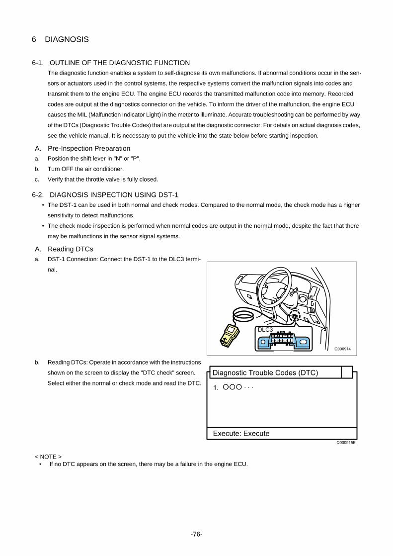
6 DIAGNOSIS
6-1. OUTLINE OF THE DIAGNOSTIC FUNCTIONThe diagnostic function enables a system to self-diagnose its own malfunctions. If abnormal conditions occur in the sen-
sors or actuators used in the control systems, the respective systems convert the malfunction signals into codes and
transmit them to the engine ECU. The engine ECU records the transmitted malfunction code into memory. Recorded
codes are output at the diagnostics connector on the vehicle. To inform the driver of the malfunction, the engine ECU
causes the MIL (Malfunction Indicator Light) in the meter to illuminate. Accurate troubleshooting can be performed by way
of the DTCs (Diagnostic Trouble Codes) that are output at the diagnostic connector. For details on actual diagnosis codes,
see the vehicle manual. It is necessary to put the vehicle into the state below before starting inspection.
A. Pre-Inspection Preparationa. Position the shift lever in "N" or "P".
b. Turn OFF the air conditioner.
c. Verify that the throttle valve is fully closed.
6-2. DIAGNOSIS INSPECTION USING DST-1• The DST-1 can be used in both normal and check modes. Compared to the normal mode, the check mode has a higher
sensitivity to detect malfunctions.
• The check mode inspection is performed when normal codes are output in the normal mode, despite the fact that there
may be malfunctions in the sensor signal systems.
A. Reading DTCsa. DST-1 Connection: Connect the DST-1 to the DLC3 termi-
nal.
b. Reading DTCs: Operate in accordance with the instructions
shown on the screen to display the "DTC check" screen.
Select either the normal or check mode and read the DTC.
< NOTE >• If no DTC appears on the screen, there may be a failure in the engine ECU.
16 15 14 13 12 11 10 9
8 7 6 5 4 3 2 1
DLC3
Q000914
Diagnostic Trouble Codes (DTC)
1. · · ·
Execute: Execute Q000915E
-76-

c. Checking the Freeze Frame Data: If the symptom that outputs a DTC cannot be duplicated, check the freeze frame data.
d. Erasing DTCs from memory: Operate in accordance with
the instructions shown on the screen to display the "DTC
check" screen. Select "Erase DTCs" to erase the DTCs.
< NOTE >• If it is not possible to erase the DTC, turn the ignition switch OFF, and repeat the process.
e. Wiring Harness and Connector Open Circuit Check
< NOTE >• If the DTC output during a diagnostic inspection (in the check mode) has identified the system with a malfunction, use
the method indicated below to narrow down the area of the malfunction.
(1) Erasing DTCs from memory: After reading the DTCs in check mode, erase the DTCs from memory.
(2) Starting the Engine: Select the check mode and start the engine.
(3) Malfunctioning system check 1: While the engine is running at idle, shake the wiring harness and connectors of the
system that output the malfunction during the diagnosis (check mode) inspection.
(4) Malfunctioning system check 2: If the MIL (Malfunction Indicator Light) illuminates when the wiring harness and con-
nectors are shaken, there is a poor contact in the wiring harness or connectors in that area.
6-3. DIAGNOSIS INSPECTION USING THE MALFUNCTION INDICATOR LIGHT• Before reading a DTC, turn the ignition switch ON to make sure the MIL (Malfunction Indicator Light) illuminates.
• Inspections in the check mode cannot be performed.
A. Reading DTCsa. Short circuiting the connector: Using the STT, short circuit between DLC1 terminals 8 (TE1) and 3 (E1) or between DLC3
terminals 13 (TC) and 4 (CG).
< CAUTION >• Never connect the wrong terminals of the connectors as this will lead to a malfunction.
NG : - OK : +
This will erase the DTC and freeze frame data.
Erase OK?
Diagnostic Trouble Code (ECD Erasure)
Q000916E
4
TE1
E1
TC
CG
1 2 3 5 6 18
7 8 9 10 11 20
12 13 14 15 16 17 21 22 23
1916 15 14 13 12 11 10 9
8 7 6 5 4 3 2 1
DLC1 DLC3
Q000917E
-77-

b. Reading DTCs 1: Turn the ignition switch ON and count the number of times the MIL (Malfunction Indicator Light) blinks
< NOTE >• If the MIL (Malfunction Indicator Light) does not output a code (the light does not blink), there may be an open circuit in
the TC terminal system or a failure in the engine ECU.• If the malfunction indicator light is constantly ON, there may be a short (pinching) in the wiring harness or a failure in the
engine ECU.• If meaningless DTCs are output, there may be a malfunction in the engine ECU.• If the MIL (Malfunction Indicator Light) illuminates without outputting a DTC while the engine operates at a minimum
speed of 1000rpm, turn the ignition switch OFF once; then resume the inspection.
c. Reading DTCs 2: If an abnormal DTC has been output, check it against the DTC list.
d. Erasing DTCs from memory: Remove the ECD fuse (15A);
after 15 seconds have elapsed, re-install the fuse.
< CAUTION >• After completing the inspection of the ECD system, erase the DTC memory, and make sure the normal code is output.
0.26sec 0.26sec
0.26sec
ON
OFF
ON
OFF
0.52sec 1.5sec 2.5sec 1.5sec 4.5sec
4.5sec
0.52sec 0.52sec
· Normal Operation
· Malfunction (Codes "12" and "23" are output.)
Jump Terminals TE1 and TC
Jump Terminals TE1 and TC
Repeat
Repeat Thereafter
MalfunctionIndicator Light
Q000918E
ECD Fuse (15A)
Engine Compartment Relay Block
Q000919E
-78-

6-4. THROTTLE BODY FUNCTION INSPECTION< CAUTION >
• Be sure to inspect the function of the throttle body after it has been disassembled and reassembled, or after any of its components have been removed and reinstalled.
• Verifying Throttle Motor: Verify that the motor generates an operating sound when the ignition switch is turned ON. Also, verify that there is no interference sound.
A. Erasing DTCsa. Connect the DST-1 to the DLC3 connector.
b. Operate in accordance with the instructions shown on the
screen to display the "DTC check" screen. Select "Erase
DTCs" to erase the DTCs.
B. Inspectiona. Start the engine and make sure the MIL (Malfunction Indicator Light) does not illuminate and the engine speed is within
standards when the air conditioner is turned ON and OFF after the engine has warmed up.
< CAUTION >• Make sure no electrical load is applied.
C. Final Inspectiona. After inspecting the throttle body function, drive test the vehicle to confirm that operation is normal.
16 15 14 13 12 11 10 9
8 7 6 5 4 3 2 1
DLC3
Q000914
NG : - OK : +
This will erase the DTC and freeze frame data.
Erase OK?
Diagnostic Trouble Code (ECD Erasure)
Q000916E
-79-

7. END OF VOLUME MATERIALS
7-1. PARTICULATE MATTER (PM)• At high concentration levels, this substance is known to affect the respiratory system. It consists of soluble organic matter
such as unburned oil, unburned diesel fuel, and other "soluble organic matter" in the exhaust gases, and insoluble or-
ganic matter such as soot (black smoke) and sulfuric acid gas.
7-2. COMMON RAIL TYPE FUEL INJECTION SYSTEM DEVELOPMENT HISTORY AND THE WORLD'S
MANUFACTURERS• The conventional injection pump faced certain issues such as injection pressure that depended on engine speed, and
limits on the maximum fuel pressure. Other types of injection control such as pilot injection also faced some difficulties.
Addressing these issues in a revolutionary manner, DENSO led the world by introducing a commercial application of the
common rail fuel injection system.
• Two types of common rail fuel injection systems are in use today. One is the common rail system that pressurizes the
fuel and injects it directly into the cylinders. DENSO was the first in the world to introduce a commercial application of
this system. This system, which is undergoing further development, has been adopted in passenger car applications.
Other companies, such as R. Bosch, Siemens, and Delphi also offer their commercial versions of this system today. The
other system is the Hydraulic Electric Unit Injection (HEUI) system, which was developed by Caterpillar in the United
States. This system uses pressurized engine oil to pressurize the fuel by actuating the piston of the nozzle (injector)
through which the pressurized fuel is injected.
7-3. HIGHER INJECTION PRESSURE, OPTIMIZED INJECTION RATES, HIGHER INJECTION TIMING
CONTROL PRECISION, HIGHER INJECTION QUANTITY CONTROL PRECISION
A. Higher Injection PressureThe fuel that is injected from the nozzle turns into finer particles as the fuel injection pressure increases. This improves
combustion and reduces the amount of smoke contained in the exhaust gases. Initially, the maximum injection pressure
of the in-line pump (A type) and the distributor pump (VE type) was 60 MPa. Due to advancement in high-pressure ap-
plications, there are some recently developed fuel injection systems that inject fuel at a pressure of 100 MPa or higher.
The second-generation common rail system injects fuel at an extremely high pressure of 180 MPa.
a. Comparing Injection Pressures
Q000920E
50
Common Rail Series
100 150 200
185
145
120
120ECD V Series
Mechanical Pump
Injection Pressure (MPa)
A Type Pump
Distributor Type Pump
NB Type Pump
ECD V4 Pump
HP0Pump
HP2Pump
HP3,4Pump
ECD V3 Pump
(1st Generation)
(2nd Generation)
1 MPa is
approximately 10.2kgf/cm2
-80-

B. Optimized Injection Rates• The injection rate is the ratio of the changes in the fuel quantity that is injected successively from the nozzle within a given
unit of time.
• As the injection pressure increases, the injection rate increases accordingly. The increase in injection rate leads to an
increase in the volume of the air-fuel mixture that is created between the start of injection until ignition (the ignition lag
period). Because this mixture is subsequently combusted at once, it creates noise (diesel knock) and NOx. For this rea-
son, it is necessary to appropriately control the injection rate by maintaining a low injection rate at the beginning of injec-
tion and supplying a sufficient quantity after the ignition. To meet this need, two-spring nozzles have been adopted and
a pilot injection system has recently been developed.
C. Higher Injection Timing Control PrecisionReducing exhaust gas emissions and fuel consumption and optimizing the injection timing are important. It is extremely
difficult to achieve the desired exhaust emission reduction levels through methods that adjust the injection timing accord-
ing to speed (or centrifugal force), such as the conventional mechanical timer. For this reason, electronically controlled
systems have been adopted to freely and precisely control the injection timing in accordance with the engine character-
istics.
D. Higher Injection Quantity Control PrecisionPower output adjustment in a diesel engine is accomplished by regulating the fuel injection quantity. Poor injection quan-
tity control precision leads to increased exhaust gas emissions, noise, and poor fuel economy. For this reason, electron-
ically controlled systems have been developed to ensure high precision injection quantity control.
t
Injection Rate High Injection Rate
Inje
ctio
n Q
ua
ntity
Q000921E
2-Spring Nozzle
Injection Rate
Common Rail System
Injection Rate Control
Inje
ctio
n Q
ua
ntity
Inje
ctio
n Q
ua
ntity
Pilot Injection
Q000922E
Electronic Control Type Mechanical Timer
Engine Speed Engine Speed
Injection Quantity
Injection Quantity
Ad
va
nce
An
gle
Ad
va
nce
An
gle
Q000923E
-81-
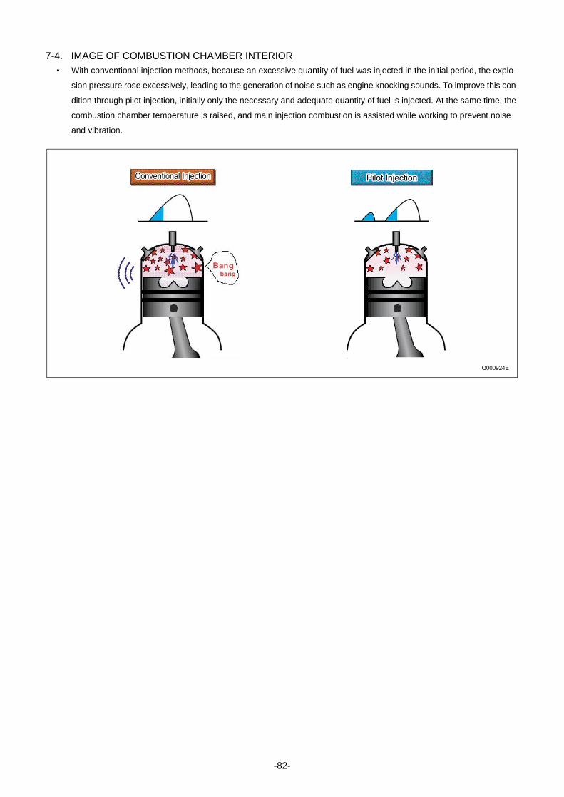
7-4. IMAGE OF COMBUSTION CHAMBER INTERIOR• With conventional injection methods, because an excessive quantity of fuel was injected in the initial period, the explo-
sion pressure rose excessively, leading to the generation of noise such as engine knocking sounds. To improve this con-
dition through pilot injection, initially only the necessary and adequate quantity of fuel is injected. At the same time, the
combustion chamber temperature is raised, and main injection combustion is assisted while working to prevent noise
and vibration.
Conventional Injection Pilot Injection
Q000924E
-82-


Published : August 2004
Edited and published by:
1-1 Showa-cho, Kariya, Aichi Prefecture, Japan
DENSO CORPORATION
Service Department