operation manual ee310 -...
TRANSCRIPT

BA_EE310_e // V2.1 // Technical data subject to change // 194474
Operation manual
EE310Humidity/Temperature
Transmitter
E+E Elektronik® Ges.m.b.H. provides no warranty of any kind for this publication and accepts no liability for improper use of the products described.
This publication might contain technical inaccuracies or typographical errors. The content is revised regularly and is not subject to change management. The manufacturer reserves the right to modify or change its described products at any time.
© Copyright E+E Elektronik® Ges.m.b.H. All rights reserved.
USA FCC noticeThis equipment has been tested and found to comply with the limits for a Class A digital device, pursuant to part 15 of the FCC Rules. These limits are designed to provide reasonable protection against harmful interference when the equipment is operated in a commercial environment. This equipment generates, uses, and can radiate radio frequency energy and, if not installed and used in accordance with the instruction manual, may cause harmful interference to radio communications. Operation of this equipment in a residential area is likely to cause harmful interference in which case the user will be required to correct the interference at his own expense.
CANADA ICES-003 Issue 5:CAN ICES-3 A / NMB-3 A
3Operating instructions for EE310 Humidity / Temperature Transmitter
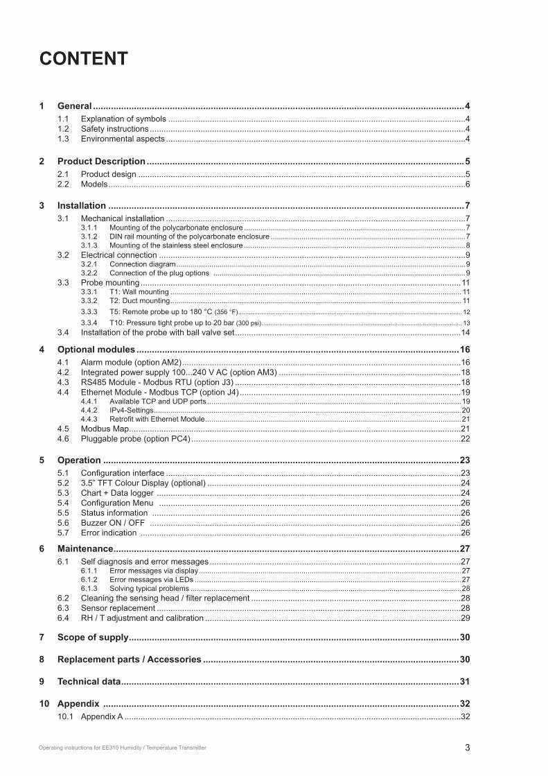
CoNtENt
1 General .................................................................................................................................................41.1 Explanation of symbols .................................................................................................................................41.2 Safety instructions .........................................................................................................................................41.3 Environmental aspects ..................................................................................................................................4
2 Product Description ............................................................................................................................52.1 Product design ..............................................................................................................................................52.2 Models ...........................................................................................................................................................6
3 Installation ...........................................................................................................................................73.1 Mechanical installation ..................................................................................................................................7
3.1.1 Mounting of the polycarbonate enclosure ............................................................................................................73.1.2 DIN rail mounting of the polycarbonate enclosure ...............................................................................................73.1.3 Mounting of the stainless steel enclosure ............................................................................................................8
3.2 Electrical connection .....................................................................................................................................93.2.1 Connection diagram .............................................................................................................................................93.2.2 Connection of the plug options ...........................................................................................................................9
3.3 Probe mounting ...........................................................................................................................................113.3.1 T1: Wall mounting .............................................................................................................................................. 113.3.2 T2: Duct mounting .............................................................................................................................................. 113.3.3 T5: Remote probe up to 180 °C (356 °F) ............................................................................................................................. 12
3.3.4 T10: Pressure tight probe up to 20 bar (300 psi) ................................................................................................................ 133.4 Installation of the probe with ball valve set ..................................................................................................14
4 optional modules ..............................................................................................................................164.1 Alarm module (option AM2) .........................................................................................................................164.2 Integrated power supply 100...240 V AC (option AM3) ...............................................................................184.3 RS485 Module - Modbus RTU (option J3) ..................................................................................................184.4 Ethernet Module - Modbus TCP (option J4) ................................................................................................19
4.4.1 Available TCP and UDP ports ............................................................................................................................194.4.2 IPv4-Settings ......................................................................................................................................................204.4.3. Retrofit.with.Ethernet.Module .............................................................................................................................21
4.5 Modbus Map ................................................................................................................................................214.6 Pluggable probe (option PC4) .....................................................................................................................22
5 operation ...........................................................................................................................................235.1. Configuration.interface ................................................................................................................................235.2 3.5” TFT Colour Display (optional) ..............................................................................................................245.3 Chart + Data logger ....................................................................................................................................245.4. Configuration.Menu.. ...................................................................................................................................265.5 Status information ......................................................................................................................................265.6 Buzzer ON / OFF .......................................................................................................................................265.7 Error indication ...........................................................................................................................................26
6 Maintenance .......................................................................................................................................276.1 Self diagnosis and error messages .............................................................................................................27
6.1.1 Error messages via display ................................................................................................................................276.1.2 Error messages via LEDs ..................................................................................................................................276.1.3 Solving typical problems ....................................................................................................................................28
6.2. Cleaning.the.sensing.head./.filter.replacement ...........................................................................................286.3 Sensor replacement ....................................................................................................................................286.4 RH / T adjustment and calibration ...............................................................................................................29
7 Scope of supply .................................................................................................................................30
8 Replacement parts / Accessories ....................................................................................................30
9 technical data ....................................................................................................................................31
10 Appendix ...........................................................................................................................................3210.1 Appendix A ..................................................................................................................................................32

4 Operating instructions for EE310 Humidity / Temperature Transmitter
1 GeneralThis manual is included in the scope of supply and serves to ensure proper handling and optimum performance of the instrument. The manual shall be read before putting the device into opera-tion. The manual is relevant for all staff involved in transport, setup, operation, maintenance and repair. The manual may not be used for the purpose of competition and shall also not be forwarded to third parties. Copies for personal use are allowed. All contents, technical data and illustrations contained in the manual are based on information available at the time of publication.
1.1 Explanation of symbolsthis symbol indicates safety information. It is essential that all safety information is strictly observed. Failure to comply with this information can lead to personal injuries or damage to property. E+E Elektronik® assumes no liability if this happens.this symbol indicates instructions. The instructions shall be observed in order to reach optimal performance of the device.
1.2 Safety instructions1.2.1. General
Excessive mechanical stress and inappropriate usage may lead to failures and shall be avoided.The sensors inside the sensing head (the tip of the sensing probe) is an Electro Static Discharge (ESD) sensitive components and shall be handled as such.Do.not.touch.the.sensing.elements.inside.the.sensing.head..The.replacement.of.the.filter.cap.shall.be.done with utmost care not to touch the sensors. Installation, electrical connection, maintenance and commissioning shall be performed by qualified.staff.only.The devices are designed for the operation with class III supply (EU) and class 2 supply (NA).
The power supply must be switched off before opening the housing!An existing Ethernet connection must be disconnected before opening the housing!
1.2.2. Alarm module with voltages >50 V (option AM2)
The optional alarm module is isolated from the low-voltage side of EE310 by a special partition; this must.remain.fitted.at.all.times.in.the.bottom.part.of.the.enclosure.The EE310 enclosure must be tightly closed during operation. An open enclosure corresponds to IP00 and exposes components carrying dangerous voltage. Any work (maintenance for instance) on the device.may.be.performed.by.qualified.staff.only.
1.2.3. Integrated power supply 100...240 V AC (option AM3)
The EE310 enclosure must be tightly closed during operation. An open enclosure corresponds to IP00 and exposes components carrying dangerous voltage. Any work (maintenance for instance) on the device.may.be.performed.by.qualified.staff.only.
1.3 Environmental aspectsProducts from E+E Elektronik® are developed and manufactured observing of all relevant requirements with respect to environment protection. Please observe local regulations for the device disposal.
For disposal, the individual components of the device must be separated according to local recycling regulations. The electronics shall be disposed of correctly as electronics waste.

5Operating instructions for EE310 Humidity / Temperature Transmitter
2 Product DescriptionEE310 is optimized for reliable measurement in demanding industrial applications. In addition to highly accurate measurement of relative humidity (RH) and temperature (T), the transmitter also calculates parameters such as dew point, absolute humidity and mixing ratio.Various models are available including wall, duct and remote probe. The remote probe can be used up to 180 °C (356 °F) and the pressure tight probe up to 20 bar (290 psi). The design of the enclosure facilitates easy mounting and maintenance. EE310 is available with polycarbonate or stainless steel IP65 enclosure.
The measured values are available on two analogue outputs and the Modbus digital interface.The state of the art TFT colour display shows up to four measurands simultaneously and offers exten-sive error diagnostics. The integrated data logging function saves all measured and calculated values to the internal memory. The data can be displayed as graph directly on the device or easily downloaded via USB interface. The E+E proprietary coating protects the sensor elements against corrosive and electrically conductive pollution.
The.outputs.can.be.freely.configured.and.an.adjustment.performed.directly.via.display.or.with.the.free.EE-PCS software using the USB service interface.
2.1 Product design
1
2
3
4
5
6
7
8
1
4
5
6
7
8
EE310-T5/T10 EE310-T1
Fig. 1 Product design
1 Upper enclosure part with electronic / display* and probe cable2 3.5” TFT colour display*3 .5.push-buttons.for.configuration.menu4 Bottom part with electrical connection, alarm* + supply module* and mounting holes5 Micro USB service interface6 Standard cable glands / connectors*7 Additional cable gland / connector*8 Probe / cable gland / connector*
* optional
6 Operating instructions for EE310 Humidity / Temperature Transmitter
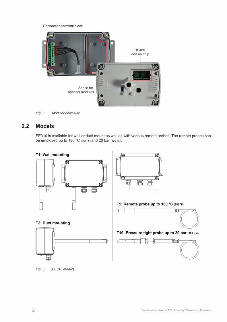
Connection terminal block
RS485 add on chip
Space for optional modules
Fig. 2 Modular enclosure
2.2 ModelsEE310 is available for wall or duct mount as well as with various remote probes. The remote probes can be employed up to 180 °C (356 °F) and 20 bar (300 psi).
T1: Wall mounting
T2: Duct mounting
T5: Remote probe up to 180 °C (356 °F)
T10: Pressure tight probe up to 20 bar (300 psi)
Fig. 3 EE310 models

7Operating instructions for EE310 Humidity / Temperature Transmitter
3 Installation
3.1 Mechanical installation
3.1.1 Mounting of the polycarbonate enclosure
•. Drill the mounting holes according to the mounting template below.•. Mount the bottom part of the enclosure with 4 screws (screw diameter < 4.2 mm (0.2”), not
included in the scope of supply).
Polycarbonate enclosure
54 (2
.13“
)
104
(4.0
9“)
71(2.80“)
5.1 (0.20“)
166 (6.54“)
180 (7.09“)
153 (6.02“)
54 (2
.13“
)
14 (0
.55“
)
166 (6.54“)
5.1 (0.20“)7 (0.28“)
Fig. 4 Dimensions and mounting template of polycarbonate enclosure in mm (inch)
3.1.2 DIN rail mounting of the polycarbonate enclosure
•. Mount the two DIN rail brackets (to be ordered separately, see chapter 8 Replacement parts / Acces-sories) onto the back side of the enclosure.
•. Snap in the enclosure onto the DIN rail
Fig. 5 DIN rail installation
8 Operating instructions for EE310 Humidity / Temperature Transmitter
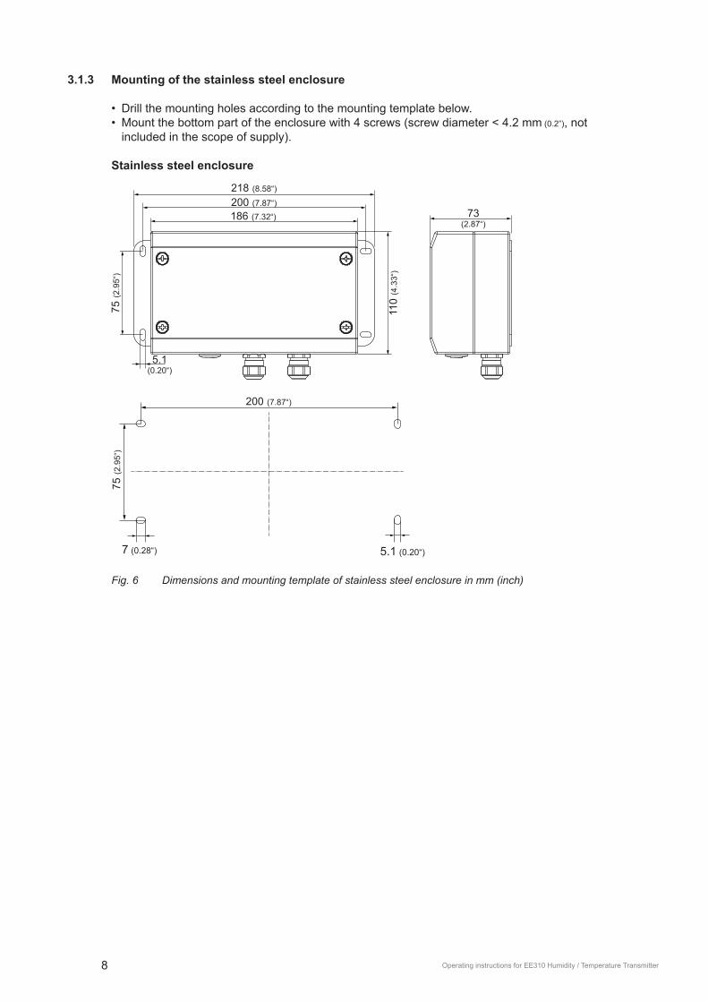
3.1.3 Mounting of the stainless steel enclosure
•. Drill the mounting holes according to the mounting template below.•. Mount the bottom part of the enclosure with 4 screws (screw diameter < 4.2 mm (0.2”), not
included in the scope of supply).
Stainless steel enclosure
75 (2
.95“
)
110
(4.3
3“)
73(2.87“)
5.1(0.20“)
218 (8.58“)
200 (7.87“)186 (7.32“)
5.1 (0.20“)7 (0.28“)
75 (2
.95“
)
200 (7.87“)
Fig. 6 Dimensions and mounting template of stainless steel enclosure in mm (inch)

9Operating instructions for EE310 Humidity / Temperature Transmitter
3.2 Electrical connectionThe.electrical.installation.of.the.EE310.shall.be.performed.by.qualified.personnel.only..Observe.all.applicable national and international requirements for the installation of electrical devices as well as for power supply according to EN 61140, class III (EU) and class 2 supply (North America).
For EE310 with alarm modul (option AM2) or integrated power supply 100...240 V AC (option AM3), the metal housing must be grounded during operation.
3.2.1 Connection diagram
V+
GND
GND
OUT 1
OUT 2
GND RS485
RS485 A (=D+)
RS485 B (=D-)
VmA
8 - 35 V DC12 - 30 V AC
1
2
3
4
5
6
7
8
Modbus RTU(galvanically isolated)
Analogue outputs
Supply
VmA
Fig. 7 Electrical connection
Analogue outputsBoth.analogue.outputs.shall.be.configured.to.either.voltage.or.current..Measurands,.analogue.range.and scaling are freely selectable. All settings can be performed via display and push buttons.or.using.the.EE-PCS.Product.Configuration.Software.
Error indicationThe analogue outputs feature an error indication function according to NAMUR NE43. In the case of an error the output signal will freeze at 21 mA or 11 V respectively.
NoteBy default the error indication is disabled.
When changing one of the analogue outputs from current to voltage and vice versa, the second output will change automatically as well. The output scaling changes automatically if it is out of physical range (i.e. 20 mA will be changed to 10 V instead of 20 V).
Check output scale after changing between voltage and current output.
3.2.2 Connection of the plug options
Option E4
power supply + analogue output
1 234
5
GND
GND Output
OUT 2
V+ OUT 1
Option E5
Modbus RTU
M16x1.5
Option E6
Modbus RTU power supply + analogue output
Option E12
Modbus RTUpower supply + analogue output
Option AM3
1 234
5
n.c.
GND Output
OUT 2
n.c. OUT 1
1 234
5
GND
GND Output
OUT 2
V+ OUT 1
Power supply + analogue output
analogue output
Modbus RTU(only with order code J3)
power supply
Analogue output
13
neutral wire(N)
neutral wire(N)
grounding(PE)
n.c.
phase(L1)
phase(L1)
n.c.
Power supply 100 - 240 V ACfor polycarbonate enclosure
Power supply 100 - 240 V ACfor stainless steel enclosure
2 143
5RS485 B (=D-)
GND RS485 (shielded)
RS485 A (=D+)
n.c.
Modbus RTU
n.c.
2 143
5RS485 B (=D-)
GND RS485 (shielded)
RS485 A (=D+)
n.c.
n.c.
2 143
5RS485 B (=D-)
GND RS485 (shielded)
RS485 A (=D+)
n.c.
Modbus RTU
n.c.

10 Operating instructions for EE310 Humidity / Temperature Transmitter
Option E4
power supply + analogue output
1 234
5
GND
GND Output
OUT 2
V+ OUT 1
Option E5
Modbus RTU
M16x1.5
Option E6
Modbus RTU power supply + analogue output
Option E12
Modbus RTUpower supply + analogue output
Option AM3
1 234
5
n.c.
GND Output
OUT 2
n.c. OUT 1
1 234
5
GND
GND Output
OUT 2
V+ OUT 1
Power supply + analogue output
analogue output
Modbus RTU(only with order code J3)
power supply
Analogue output
13
neutral wire(N)
neutral wire(N)
grounding(PE)
n.c.
phase(L1)
phase(L1)
n.c.
Power supply 100 - 240 V ACfor polycarbonate enclosure
Power supply 100 - 240 V ACfor stainless steel enclosure
2 143
5RS485 B (=D-)
GND RS485 (shielded)
RS485 A (=D+)
n.c.
Modbus RTU
n.c.
2 143
5RS485 B (=D-)
GND RS485 (shielded)
RS485 A (=D+)
n.c.
n.c.
2 143
5RS485 B (=D-)
GND RS485 (shielded)
RS485 A (=D+)
n.c.
Modbus RTU
n.c.
Fig. 8 Plug options for EE310 (front connector view)
External diameter of the supply cable for option AM3: 10-12 mm (0.39-0.47”). Maximum wire cross section for AM3 connecting cable: 1.5 mm² (AWG 16) .
External diameter of the cable for Modbus RTU and analogue output female plug: 4 - 6 mm (0.16 - 0.24”). Maximal wire cross section for connecting cable: 0.5 mm² (AWG 21).
11Operating instructions for EE310 Humidity / Temperature Transmitter
3.3 Probe mounting
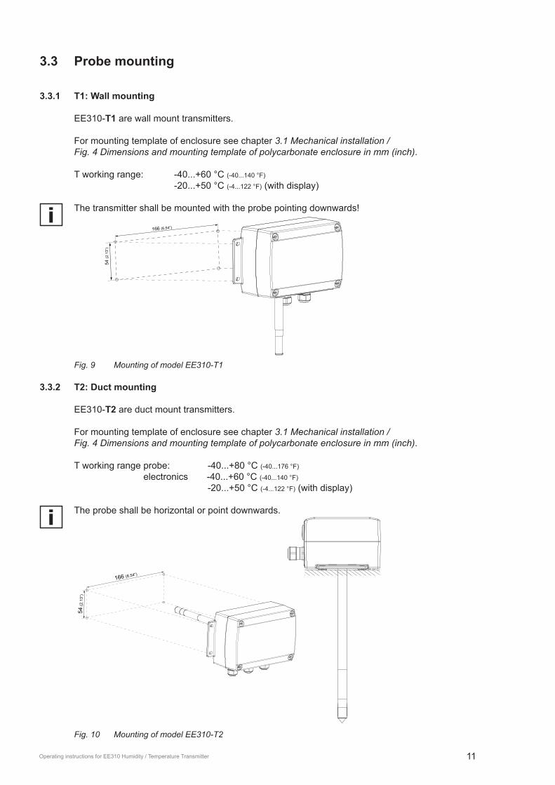
3.3.1 t1: Wall mounting
EE310-t1 are wall mount transmitters.
For mounting template of enclosure see chapter 3.1 Mechanical installation / Fig. 4 Dimensions and mounting template of polycarbonate enclosure in mm (inch).
T working range: -40...+60 °C (-40...140 °F)
-20...+50 °C (-4...122 °F) (with display)
The transmitter shall be mounted with the probe pointing downwards!
166 (6.54“)
54 (2
.13“
)
Fig. 9 Mounting of model EE310-T1
3.3.2 t2: Duct mounting
EE310-t2 are duct mount transmitters.
For mounting template of enclosure see chapter 3.1 Mechanical installation / Fig. 4 Dimensions and mounting template of polycarbonate enclosure in mm (inch).
T working range probe: -40...+80 °C (-40...176 °F) electronics -40...+60 °C (-40...140 °F)
-20...+50 °C (-4...122 °F) (with display) The probe shall be horizontal or point downwards.
166 (6.54“)
54 (2
.13“
)
Fig. 10 Mounting of model EE310-T2

12 Operating instructions for EE310 Humidity / Temperature Transmitter
3.3.3 t5: Remote probe up to 180 °C (356 °F)
EE310-t5 are transmitters with remote probe.
For mounting template of enclosure see chapter 3.1 Mechanical installation / Fig. 4 Dimensions and mounting template of polycarbonate enclosure in mm (inch).
T working range probe: -40...+180 °C (-40...176 °F) electronics: -40...+60 °C (-40...140 °F)
-20...+50 °C (-4...122 °F) (with display)
Mounting the remote sensing probe of EE310-t5For.mounting.the.probe.into.a.separation.wall.use.the.stainless.steel.mounting.flange.(see. chapter 8 Replacement parts / Accessories). The immersion depth is adjustable. The probe shall be horizontal.
In case of mounting into a separation wall, it is of paramount importance for accurate measurement to avoid T gradients along the probe. In case of large T difference between the two sides of the separa-tion wall, it is highly recommended to insert the probe completely (up to the cable outlet) into the wall. Should this not be possible, place a thermal isolation layer on the part of the probe outside the wall (on the cable side).
The.stainless.steel.mounting.flange.is.not.appropriate.for.pressure.tight.mounting..For.pressure.tight.requirements use EE310-T10.
For probe hanging onto its cable from the ceiling in applications where condensation is likely to happen it is important to avoid condense water getting from the cable to the probe and into the sensing head. For this use the drip water protection.
Ø 12
0.5“
461.8“
34 1.3“
853.3“
drip water protection
hanging probeprobe into separation wall
13 0.5“
bow for draining condense water
temperature gradient alongthe probe shall be avoided
sealing
Fig. 11 Mounting the remote probe of EE310-T5
13Operating instructions for EE310 Humidity / Temperature Transmitter
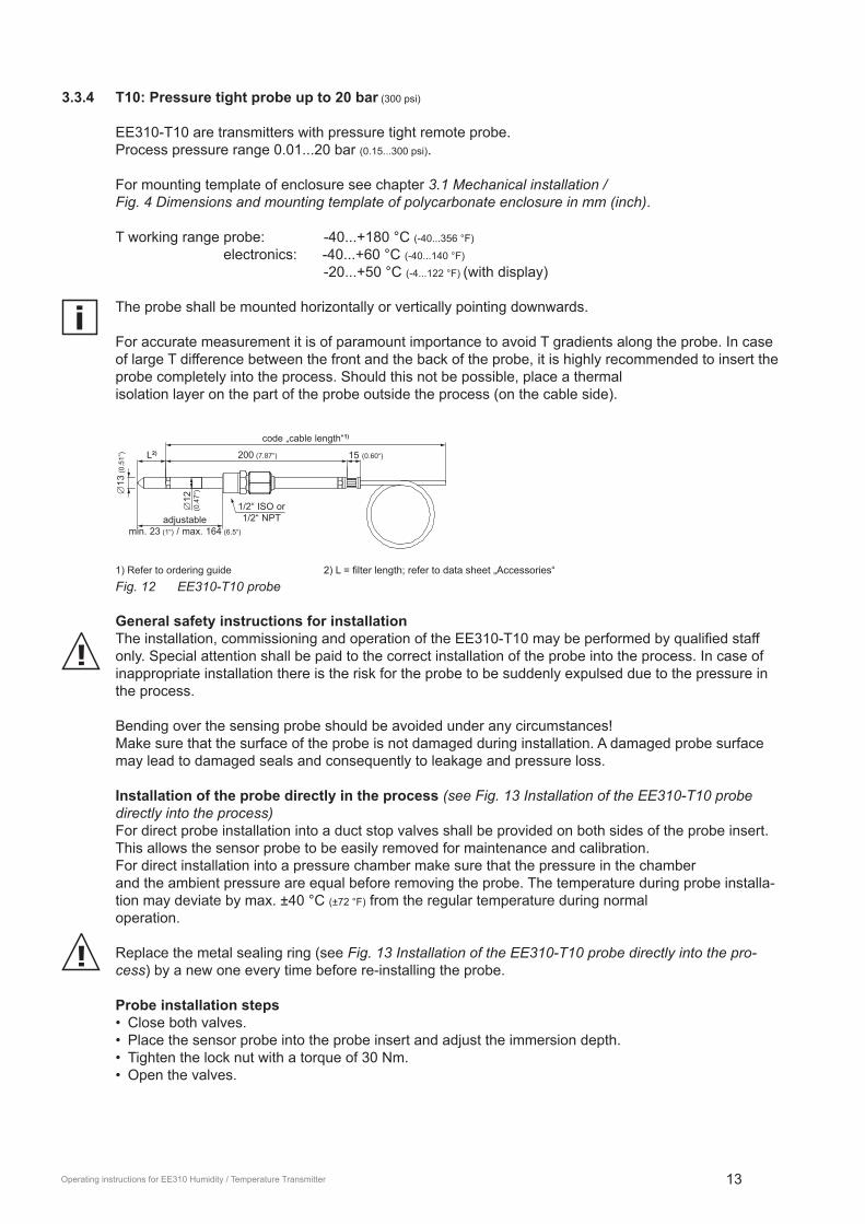
3.3.4 t10: Pressure tight probe up to 20 bar (300 psi)
EE310-T10 are transmitters with pressure tight remote probe. Process pressure range 0.01...20 bar (0.15...300 psi).
For mounting template of enclosure see chapter 3.1 Mechanical installation / Fig. 4 Dimensions and mounting template of polycarbonate enclosure in mm (inch).
T working range probe: -40...+180 °C (-40...356 °F) electronics: -40...+60 °C (-40...140 °F)
-20...+50 °C (-4...122 °F) (with display) The probe shall be mounted horizontally or vertically pointing downwards.
For accurate measurement it is of paramount importance to avoid T gradients along the probe. In case of large T difference between the front and the back of the probe, it is highly recommended to insert the probe completely into the process. Should this not be possible, place a thermal isolation layer on the part of the probe outside the process (on the cable side).
code „cable length“1)
200 (7.87“)
adjustablemin. 23 (1“) / max. 164 (6.5“)
∅12
(0
.47“
)
L2) 15 (0.60“)
1/2“ ISO or1/2“ NPT
∅13
(0.5
1”)
1).Refer.to.ordering.guide. . 2).L.=.filter.length;.refer.to.data.sheet.„Accessories“.
Fig. 12 EE310-T10 probe
General safety instructions for installationThe.installation,.commissioning.and.operation.of.the.EE310-T10.may.be.performed.by.qualified.staff.only. Special attention shall be paid to the correct installation of the probe into the process. In case of inappropriate installation there is the risk for the probe to be suddenly expulsed due to the pressure in the process.
Bending over the sensing probe should be avoided under any circumstances! Make sure that the surface of the probe is not damaged during installation. A damaged probe surface may lead to damaged seals and consequently to leakage and pressure loss.
Installation of the probe directly in the process (see Fig. 13 Installation of the EE310-T10 probe directly into the process)For direct probe installation into a duct stop valves shall be provided on both sides of the probe insert. This allows the sensor probe to be easily removed for maintenance and calibration.For direct installation into a pressure chamber make sure that the pressure in the chamberand the ambient pressure are equal before removing the probe. The temperature during probe installa-tion may deviate by max. ±40 °C (±72 °F) from the regular temperature during normal operation.
Replace the metal sealing ring (see Fig. 13 Installation of the EE310-T10 probe directly into the pro-cess) by a new one every time before re-installing the probe.
Probe installation steps•. Close both valves.•. Place the sensor probe into the probe insert and adjust the immersion depth.•. Tighten the lock nut with a torque of 30 Nm. •. Open the valves.

14 Operating instructions for EE310 Humidity / Temperature Transmitter
Observe strictly the tightening torque. A torque lower than 30 Nm results in a smaller retention force of the clamping sleeve. This leads the risk of sudden expulsion of the sensing probe due to the pressure. A torque higher than 30 Nm may lead to permanent deformation of the clamping sleeve and the sensing probe. This would make.the.removal.and.re-installation.of.the.probe.difficult.or.even.impossible.
fixed installation (pressure tight up to 20 bar (300 psi))
stop valve stop valve
1/2” ISO or 1/2“ NPT
inside diameter≥ 13 mm (0.55”)
metal sealing ring
Fig. 13 Installation of the EE310-T10 probe directly into the process
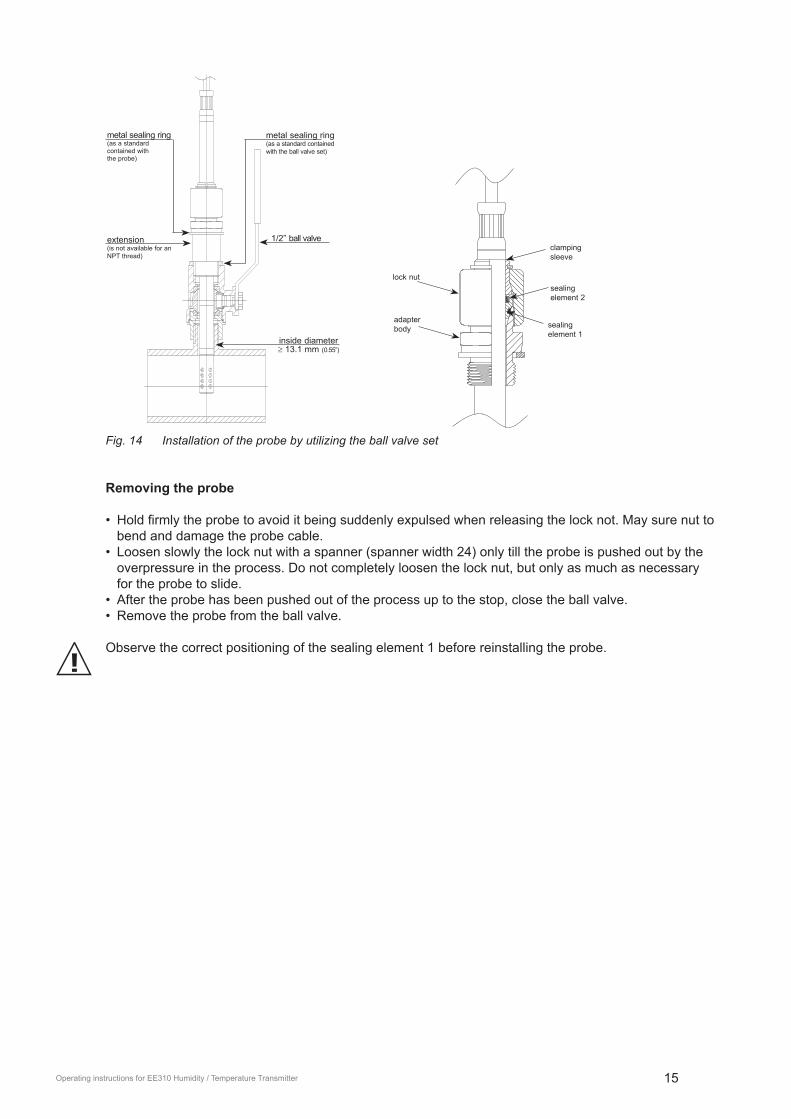
3.4 Installation of the probe with ball valve setThe ball valve set allows for installation and removal of the probe without process interruption.For.mounting.into.a.duct,.the.ball.valve.shall.be.installed.perpendicular.to.the.flow.direction.
The two metal sealing rings (see Fig. 14 Installation of the probe by utilizing the ball valve set) shall be replaced every time prior to re-installing the probe.
The temperature during probe installation may deviate by max. ±40 °C (±72 °F) from the regular tempera-ture during normal operation.
Installation of the probe (see Fig. 14 Installation of the probe by utilizing the ball valve set):•. Install the probe into the ball valve while the ball valve is closed.•. Open the ball valve.•. Slide the probe through the ball valve to the desired immersion depth. Depending on the
process pressure additional tools may be necessary for pushing the probe into the process. Make sure not to damage the probe and the cable.
•. Tighten the lock nut with a torque of 30 Nm.
Observe strictly the tightening torque. A torque lower than 30 Nm results a smaller retention force of the clamping sleeve. This leads the risk of sudden expulsion of the sensing probe due to the pressure. A torque higher than 30 Nm may lead to permanent deformation of the clamping sleeve and the sensing probe..This.would.make.the.removal.and.re-installation.of.the.probe.difficult.or.even.impossible.
15Operating instructions for EE310 Humidity / Temperature Transmitter
metal sealing ring(as a standard contained withthe probe)
metal sealing ring(as a standard contained with the ball valve set)
1/2” ball valveextension(is not available for an NPT thread)
inside diameter≥ 13.1 mm (0.55”)
clampingsleeve
lock nut
adapter body
sealing element 2
sealing element 1
Fig. 14 Installation of the probe by utilizing the ball valve set
Removing the probe
•. Hold.firmly.the.probe.to.avoid.it.being.suddenly.expulsed.when.releasing.the.lock.not..May.sure.nut.to.bend and damage the probe cable.
•. Loosen slowly the lock nut with a spanner (spanner width 24) only till the probe is pushed out by the overpressure in the process. Do not completely loosen the lock nut, but only as much as necessary for the probe to slide.
•. After the probe has been pushed out of the process up to the stop, close the ball valve.•. Remove the probe from the ball valve.
Observe the correct positioning of the sealing element 1 before reinstalling the probe.
16 Operating instructions for EE310 Humidity / Temperature Transmitter
4 optional modules
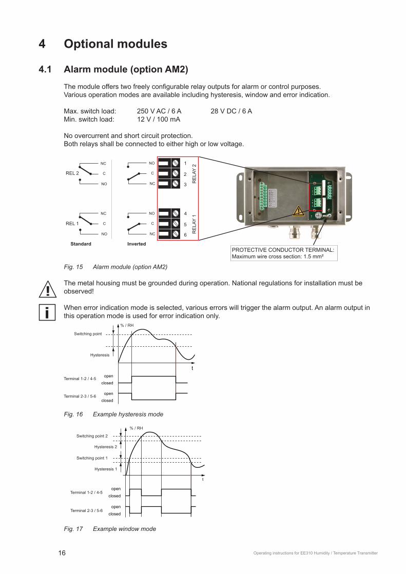
4.1 Alarm module (option AM2)The.module.offers.two.freely.configurable.relay.outputs.for.alarm.or.control.purposes.Various operation modes are available including hysteresis, window and error indication.
Max. switch load: 250 V AC / 6 A 28 V DC / 6 AMin. switch load: 12 V / 100 mA
No overcurrent and short circuit protection.Both relays shall be connected to either high or low voltage.
NO
NC
C
NC 6
NO 4
C 5
NC 3
NO 1
C 2
NO
NC
C
Standard Inverted
REL 1
REL 2
RE
LAY
2R
ELA
Y 1
PROTECTIVE CONDUCTOR TERMINAL: Maximum wire cross section: 1.5 mm²
Fig. 15 Alarm module (option AM2)
The metal housing must be grounded during operation. National regulations for installation must be observed!
When error indication mode is selected, various errors will trigger the alarm output. An alarm output in this operation mode is used for error indication only.
Switching point
% / RH
Hysteresis
t
closed
open
closed
openTerminal 2-3 / 5-6
Terminal 1-2 / 4-5
Fig. 16 Example hysteresis mode
Terminal 2-3 / 5-6
Terminal 1-2 / 4-5
Switching point 2
Hysteresis 2
% / RH
Hysteresis 1
Switching point 1
t
closed
open
closed
open
Fig. 17 Example window mode

17Operating instructions for EE310 Humidity / Temperature Transmitter
Switching point
% / RH
Standard
Inverted
Power
Hysteresis
Terminal 2-3
Terminal 5-6
t
closed
open
closed
open
ONOFF
Fig. 18 Example of alarm in case of power supply failure using inverted alarm outputs.
The measurands at the outputs as well as switching points, hysteresis and the default state (standard /.inverted).can.be.set.via.EE-PCS.Product.Configuration.Software.or.using.the.display.and.the.push.buttons.
Menu
Alarm number
Alarm output*
Alarm 2
Alarm 1
Mode
Switch hysteresis
Measurand
Switching point
Switching point
Hysteresis
Standard
Inverted
Normal state
Switch window
Measurand
Switching point low
Switching point
Hysteresis
Switching point high
Switching point
Hysteresis
Standard
Inverted
Normal state
Error indication
Standard
Inverted
Normal state
OFFTemperature [°C]Temperature [°F]Temperature [K]Rel. humidity [%]
Vap. p. pressure [mbar]Vap. p. pressure [psi]
Dew point [°C]Dew point [°F]
Wet bulb temp. [°C]Wet bulb temp. [°F]Abs. humidity [g/m³]Abs. humidity [gr/ft³]Mixing ratio [g/kg]Mixing ratio [gr/lb]Enthalpy [kJ/kg]
Enthalpy [ft lbf/lb]Enthalpy [BTU/lb]Frost point [°C]Frost point [°F]
Water activity [aw]Saturation [%]
Water content [ppm]Wet bulb temp. [K]
Dew point [K]Frost point [K]
Volume concentr. [ppm]
* Menu only available with connected alarm module during EE310 start-up

18 Operating instructions for EE310 Humidity / Temperature Transmitter
4.2 Integrated power supply 100...240 V AC (option AM3)This module allows the EE310 to be powered with 100...240 V AC (50/60 Hz), 2 VA.
plastic enclosure stainless steel enclosure
Fig. 19 Power supply module (option AM3)
Pin assignment of the plug connection see chapter 3.2.2 Connection of the plug options.
The AM3 option includes a 1.25 A fuse on the 100-240 V side. This fuse may not be replaced by the user, but only by the E+E Service. The protection of the supply cable against excess current and short-circuit must be designated to a wire cross section of 0.8 mm² (AWG 18) (6A fuse).The metal housing must be grounded during operation.National regulations for installation must be observed!
4.3 RS485 Module - Modbus RtU (option J3)Instructions for Modbus-Protocol-Setup please see Application Note AN0103 (www.epluse.com/EE310).
Up to 32 EE310 transmitters with Modbus RTU interface can be connected in a RS-485 bus system.Slave n
(max. 32) Slave 2
Slave 1Slave 3
Modbus RTU Master
Fig. 20 Two wire RS485 network
Both ends of the network shall be terminated with a resistor Ra=120 Ohm.
The.setup.of.the.Modbus.RTU.communication.can.be.performed.via.EE-PCS.Product.Config- uration Software or via display and push buttons.
19Operating instructions for EE310 Humidity / Temperature Transmitter
Parity
None
Odd
Even
Baudrate value
value
value
Stop bits
Address
Menu
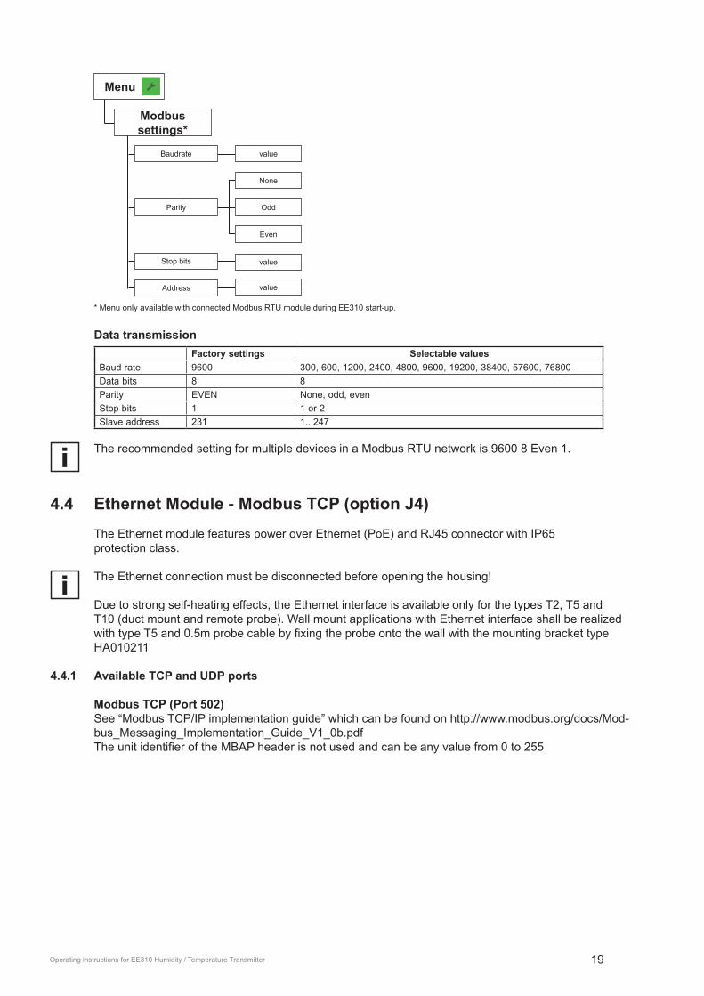
Modbus settings*
* Menu only available with connected Modbus RTU module during EE310 start-up.
Data transmissionFactory settings Selectable values
Baud rate 9600 300, 600, 1200, 2400, 4800, 9600, 19200, 38400, 57600, 76800 Data bits 8 8Parity EVEN None, odd, evenStop bits 1 1 or 2Slave address 231 1...247
The recommended setting for multiple devices in a Modbus RTU network is 9600 8 Even 1.
4.4 Ethernet Module - Modbus tCP (option J4)The Ethernet module features power over Ethernet (PoE) and RJ45 connector with IP65protection class.
The Ethernet connection must be disconnected before opening the housing!
Due to strong self-heating effects, the Ethernet interface is available only for the types T2, T5 and T10 (duct mount and remote probe). Wall mount applications with Ethernet interface shall be realized with.type.T5.and.0.5m.probe.cable.by.fixing.the.probe.onto.the.wall.with.the.mounting.bracket.type.HA010211
4.4.1 Available tCP and UDP ports
Modbus tCP (Port 502)See “Modbus TCP/IP implementation guide” which can be found on http://www.modbus.org/docs/Mod-bus_Messaging_Implementation_Guide_V1_0b.pdfThe.unit.identifier.of.the.MBAP.header.is.not.used.and.can.be.any.value.from.0.to.255

20 Operating instructions for EE310 Humidity / Temperature Transmitter
HttP-Webserver (Port 80)For a quick communication check you can enter the desired IP in a web browser to get a brief system status.
Alternatively you can send an ICMP echo request (“ping”) to check correct communication settings.
EE31-over-UDP (Port 5234)Backwards compatible with EE31 device series.Communication via Ethernet takes place by means of UDP packets, which transport a command or a command response in EE31 protocol format as payload data.See “Ethernet - communication protocol” which can be found on https://www.epluse.com/en/ser-vice-support/download-center/
4.4.2 IPv4-Settings
Factory setting:IP-Address: 192.168.0.64Subnet-Mask: 255.255.255.0Gateway: 192.168.0.1DNS: 192.168.0.1
DHCP options can be set with jumper on the PCBFactory setting: DHCP disabled (static IP)
Fig. 21 Ethernet Module - DHCP setting
The.setup.of.the.Modbus.TCP.communication.can.be.performed.via.EE-PCS.Product.Config- uration Software or via display and push buttons.Modifying.the.IP-Address.via.EE-PCS.or.display.is.possible.only.when.the.DHCP.jumper.is.configured.“Static”. Otherwise the IP-settings are read-only

21Operating instructions for EE310 Humidity / Temperature Transmitter
IP address
Subnet mask
Type shows the status of the DHCP setting
value
value
value
value
Gateway
DNS server
Menu
IP settings
IPv6 is not supportedSupported Ethernet standard: 802.3i/u/x and af
4.4.3 Retrofit with Ethernet Module
The.EE310.can.be.retrofitted.with.an.Ethernet.Module..Before.retrofitting.please.make.sure,.that.the.Firmware.on.your.device.is.updated.to.the.latest.version.by.using.the.Configuration.Software.EE-PCS.•. Firmware for Transmitter: V 1.0.22 or higher•. Firmware for Display: V 1.0.9 or higher
Order code: HA010606 for remote probe type T5 and T10HA010607 for duct mounting type T2
4.5 Modbus Map
Register[DEC]
Protocol address [HEX]
Measured value Unit type
Read registers: function code 0x03 / 0x0431021 3FC Relative humidity % 32-bit float31003 3EA Temperature °C 32-bit float31005 3EC Temperature °F 32-bit float31105 450 Dew point temperature °C 32-bit float31107 452 Dew point temperature °F 32-bit float31131 46A Frost point / Dew point temperature °C 32-bit float31133 46C Frost point / Dew point temperature °F 32-bit float31113 458 Absolute humidity g/m3 32-bit float31115 45A Absolute humidity gr/ft3 32-bit float31121 460 Mixing ratio g/kg 32-bit float31123 462 Mixing ratio gr/lb 32-bit float31109 454 Wet bulb temperature °C 32-bit float31111 456 Wet bulb temperature °F 32-bit float31125 464 Specific enthalpy kJ/kg 32-bit float31129 468 Specific enthalpy BTU/lb 32-bit float31127 466 Specific enthalpy ft lbf/lb 32-bit float31101 44C Water vapour partial pressure mbar 32-bit float31103 44E Water vapour partial pressure psi 32-bit float31151 47E Volume concentration ppm 32-bit float35001 1388 Air pressure mbar 32-bit float
Write registers: function code 0x06 for 16-bit and 0x10 (decimal: 16) for 32-bit0001 0 Slave-ID / 16-bit integer5001 1388 Air pressure mbar 32-bit float

22 Operating instructions for EE310 Humidity / Temperature Transmitter
4.6 Pluggable probe (option PC4)EE310-t5 and EE310-t10 transmitters are optionally available with pluggable sensing probe, which is attached to the EE310 enclosure by a push-pull plug. If the probe or the probe cable gets damaged it is possible to easily replace the probe without humidity and temperature adjustment. The replacement probe (see order information below) is supplied with a set of 7 individual parameters.
If you use two or more devices at the same time, make sure not to mix up the sensors! You can read out the serial number of the connected sensor by scanning the barcode on the basic unit.
1.
2.
Barcode for probe serial num
ber
Fig. 22 Pluggable probe
Probe replacement procedure•. Plug off the damaged probe•. Plug on the new probe•. Update.the.7.parameters.with.EE-PCS.Product.Configuration.Software.or.via.display.and.push.but-
tons.
Working pressure
Probe replacement
Parameters
Humidity coefficient
Resistance R0
Capacity C76
Capacity gain
Capacity offset
Temperature coefficient.TK
Resistance Offset
Menu
Device settings
Note: When replacing the probe, the factory calibration loses its validity. A calibration to verify accuracy is recommended but not mandatory.

23Operating instructions for EE310 Humidity / Temperature Transmitter
order information for replacement probe
PE310type t5 t10Filter stainless steel sintered F4 F4
PTFE F5H2O2 F12stainless steel - metal grid (up to 180 °C / 356 °F) F9 F9
Cable length(incl. probe length)
2 m (6.6 ft) K2 K25 m (16.4 ft) K5 K510 m (32.8 ft) K10 K10
Probe length65 mm (2.55“) L65200 mm (7.87“) L200 L200400 mm (15.75“) L400 L400
Process connection 1/2“ ISO thread PA231/2“ NPT thread PA25
optional features E+E sensor coating C1 C1
Tab. 1 Ordering code for replacement probe
5 operation
5.1 Configuration interfaceThe.transmitter.can.be.used.for.configuration.or.calibration.via.the.micro.USB.configuration. interface. An additional supply is not necessary. After.the.USB.cable.is.connected,.the.transmitter.is.initialised.and.the.configuration.is.loaded..The.green.status.LED.flashes.and.indicates.proper.operation.of.the.electronics..
Blind cover USB cable
Fig. 23 Remove the blind cover and plug in the USB cable
PCB
LED 1 LED 2
LED 4LED 3
Current output
Error LED
error LED on = error category 1error LED flashes = error category 2
Voltage output
power supply/main board
Fig. 24 Status LEDs are located at the USB port

24 Operating instructions for EE310 Humidity / Temperature Transmitter
5.2 3.5” tFt Colour Display (optional)The.EE310.display.includes.a.data.logger.and.push.buttons.for.full.configuration.of.the.device..Upon.start-up.of.an.EE310.with.display,.the.data.logger.and.the.configuration.menu.will.be. initialised.during.the.first.5.seconds..
1
2
3
4
5
Chart + data logger
Configuration menu
Status information
Buzzer ON / OFF
Error indication / information
Fig. 25 Display with push buttons
5.3 Chart + Data logger The TFT display with the integrated data logging function saves all measured and calculated values to the internal memory. The data logger has a real time clock (UTC time) with a battery back-up.
Changing the UTC time erases all stored data.
The data logger can save 20.000 values for each measurand. The logging interval is to be set by the user from 1 second to 12 hours.
The data logger setup can be performed via display and push buttons.
Menu
Sampling rate
Data-loggingOFF
1 s / 10 s1 min / 5 min / 15 min / 30 min
1 h / 5 h / 12 h
The data logger menu is also used to select the logged data to be shown as a graph as well as for scal-ing the graph.
25Operating instructions for EE310 Humidity / Temperature Transmitter
Menu
Sampling rate
Data-logging
Axis 1
Measurand
Axis 2
Measurand
Scale maximum value
value
value
value
Scale minimum
OFF1 s / 10 s
1 min / 5 min / 15 min / 30 min1 h / 5 h / 12 h
Delete saved values
OFFTemperature [°C]Temperature [°F]Temperature [K]Rel. humidity [%]
Vap. p. pressure [mbar]Vap. p. pressure [psi]
Dew point [°C]Dew point [°F]
Wet bulb temp. [°C]Wet bulb temp. [°F]Abs. humidity [g/m³]Abs. humidity [gr/ft³]Mixing ratio [g/kg]Mixing ratio [gr/lb]Enthalpy [kJ/kg]
Enthalpy [ft lbf/lb]Enthalpy [BTU/lb]Frost point [°C]Frost point [°F]
Water activity [aw]Saturation [%]
Water content [ppm]Wet bulb temp. [K]
Dew point [K]Frost point [K]
Volume concentr. [ppm]
Scale minimum
Scale maximum
1 Home button
2 Configuration incl. data logger menu
3 Time scale for the graph (5 min - 3 months)
4 CursorAxis 1 value
(cursor position)
Axis 1Axis 2
Axis 2 value(cursor position)
Date(cursor position)
Time(cursor position)
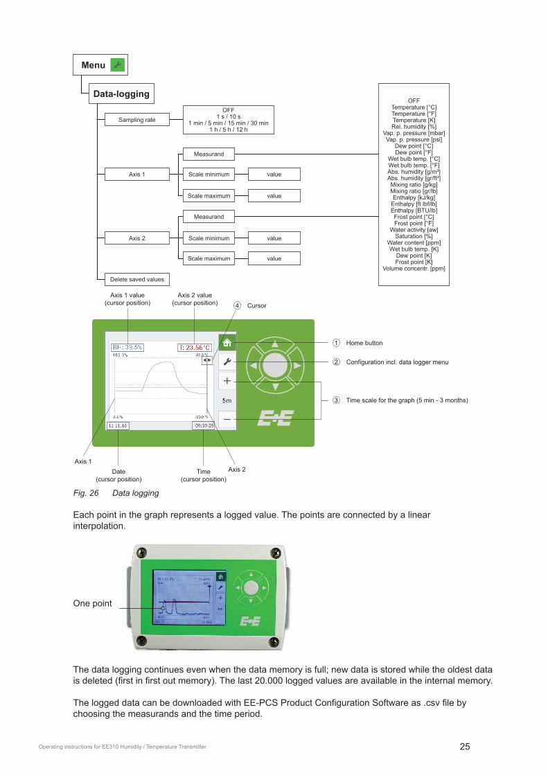
Fig. 26 Data logging
Each point in the graph represents a logged value. The points are connected by a linear interpolation.
One point
The data logging continues even when the data memory is full; new data is stored while the oldest data is.deleted.(first.in.first.out.memory)..The.last.20.000.logged.values.are.available.in.the.internal.memory.
The.logged.data.can.be.downloaded.with.EE-PCS.Product.Configuration.Software.as..csv.file.by.choosing the measurands and the time period.

26 Operating instructions for EE310 Humidity / Temperature Transmitter
5.4 Configuration Menu Detailed.information.to.the.configuration.menu.see.chapter.10 Appendix.
Menu
Data-logging
Display settings
Analog output
Customer adjustment
Alarm output*
Modbus settings*
configuration of data logger/graph - sampling rate | graphs
setting of display layout - measurands | brightness | display alarm
output configuration - mode | measurands | scaling | error indication
relay configuration - mode | set points | state
adjustment - 1 and 2 point humidity/temperature adjustment | reset to factory adjustment | calibration status
configuration of Modbus RTU data transmission
Device settings
Status
settings - language | date, time | parameters | password protection
status and device information
IP settings* configuration of Ethernet Module
* Menu only available with connected corresponding modules.
5.5 Status information i
The status information shows all actual EE310 settings.
Fig. 27 Status information
5.6 Buzzer oN / oFF
Buzzer ON Buzzer OFF
5.7 Error indication When an error occurs, the error indication shows the error code.

27Operating instructions for EE310 Humidity / Temperature Transmitter
6 Maintenance
6.1 Self diagnosis and error messages
6.1.1 Error messages via display
Error description Error code (display) Error category Recommended action
Voltage out short circuit - output 1 only* 1.1
1
Check wiring of outputsVoltage out short circuit - output 2 only* 1.2Voltage out short circuit - both outputs* 1.3Current loop open - output 1 only 2.1
Check wiring of outputsCurrent loop open - output 2 only 2.2Current loop open - both outputs 2.3RH sensor dirty 3.x Cleaning sensor
Hardware error5.x
2 Return the faulty unit to E+E for service
6.x8.x
Temperature measurement failure 7.x
Humidity measurement failure 9.x10.x
* not available with 0 - 1 V output
Tab. 2 Overview of error codes
Error category 1 = non-critical error, can be solved by the user •. The display blinks and the buzzer beeps every 10 seconds.•. The red status LED lights continuously.
Error category 2 = critical error, return the device to E+E for service•. The display blinks and the buzzer beeps continuously.•. The red status LED flashes.
6.1.2 Error messages via LEDs
Four status LEDs placed on both sides of a PCB are located close to the USB service interface, under a blind cover.
PCB
LED 1 LED 2
LED 4LED 3
Current output
Error LED
error LED on = error category 1error LED flashes = error category 2
Voltage output
power supply/main board
Fig. 28 Status LEDs
LED 1 (blue): analogue output is set to voltage.
LED 2 (orange): analogue output is set to current.
LED 3 (flashing green): supply voltage applied (microprocessor is active).
LED 4 (red): constant lit: error category 1 flashes:.error.category.2

28 Operating instructions for EE310 Humidity / Temperature Transmitter
6.1.3 Solving typical problems
Error description Likely causes and solutions
Display shows incorrect values
Error during re-adjustment of the transmitter. →.Reset.to.factory.calibration.and.repeat.the.adjustment.routine.Filter soiled →.Replace.filter.Output.configured.incorrectly →.check.configuration
Long response timeFilter soiled →.Replace.filterInappropriate.filter.type →.Contact.E+E.representative.for.advice.
High humidity values - red LED blinks
Water in sensing head →..Investigate.the.cause.for.water./.condensation...
Contact E+E representative for advice. Inappropriate.filter.type →.Contact.E+E.representative.for.advice.
Tab. 3 Self diagnosis
6.2 Cleaning the sensing head / filter replacementIn case of dusty, oily and polluted environment:•. The.filter.cap.shall.be.replaced.once.in.a.while.with.an.E+E.original.one..A.polluted.filter.cap.causes.
longer response time of the device.•. If needed, the sensing head can be cleaned. For cleaning instructions please see
www.epluse.com/EE310.

29Operating instructions for EE310 Humidity / Temperature Transmitter
6.3 RH / t adjustment and calibrationHumidity calibration and adjustmentDepending on the application and the requirements of certain industries, there might arise the need for periodical humidity calibration (comparison with a reference) or adjustment (bringing the device in line with a reference).
Calibration and adjustment at E+E ElektronikCalibration and/or adjustment can be performed in the E+E Elektronik calibration laboratory. For infor-mation on the E+E capabilities in ISO or accredited calibration please see www.eplusecal.com.
Calibration and adjustment by the userDepending on the level of accuracy required, the humidity reference can be:•. Humidity Calibrator (e.g. Humor 20), please see www.epluse.com/humor20.•. Handheld device (e.g. Omniport30), please see www.epluse.com/omniport30.•. Humidity calibration Kit (e.g. E+E Humidity Standards), please see www.epluse.com/EE310.
Perform.1.or.2.point.adjustment.via.EE-PCS.Product.Configuration.Software.or.via.display. (details see below).
Menu
Customer adjustment
OffsetReference value
Current measured value
Calibration status iReset to factory calibration
2 point adjustment
Reference value low
Reference value high
Rel. humidity
Temperature
value
valueReference value
Current measured value
Fig. 29 Adjustment menu
measurement value
Measured value
Dis
play
ed v
alue
reference value
Offset adjustment point
FACTORY / CURRENT ADJUSTMENT
NEW ADJUSTMENT
Fig. 30 Offset adjustment

30 Operating instructions for EE310 Humidity / Temperature Transmitter
measurement value 1
Measured value
Dis
play
ed v
alue
reference value 1
ADJUSTMENT POINT LOW ADJUSTMENT POINT HIGH
reference point LOWfactory setting: 30 % RH
reference point HIGHfactory setting: 80 % RH
FACTORY / CURRENT ADJUSTMENTADJUSTMENT LOW
measurement value 2
reference value 2
ADJUSTMENT HIGH
Fig. 31 2 point adjustment procedure
7 Scope of supplyIncluded in the scope of supply of:
EE310 according to ordering guide all versionsOperation Manual English* all versionsInspection.certificate.according.to.DIN.EN.10204.–.3.1 all versionsMating plug for integrated power supply AM3Mating plug RKC 5/7 AM3 / E4 / E6 / E12Mating plug RSC 5/7 (2 pcs. for option E12) E5 / E6 / E12Mating plug HPP V4 RJ45 Cat5 J4
*) Other languages can be downloaded at www.epluse.com/EE310
Tab. 4 Scope of supply
8 Replacement parts / Accessoriessee data sheet “Accessories”
Description order code- Filter caps HA0101xx- Mounting flange stainless steel HA010201- Drip water protection HA010503- RS485 kit for retrofitting HA010605- Ethernet Module for retrofitting plastic housing HA010606 for remote probe type T5, T10 HA010607 for duct mounting type T2- Bracket for installation onto mounting rails1) HA010203- Replacement probes2) see 4.6 Pluggable probe (option PC4)- Humidity calibration kit see data sheet „Humidity calibration kit“
1) 2 pieces necessary per enclosure.
2) Only for devices with pluggable probe option PC4.
31Operating instructions for EE310 Humidity / Temperature Transmitter
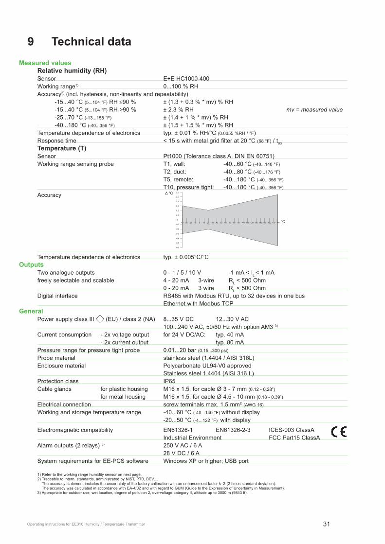
9 technical dataMeasured values Relative humidity (RH) Sensor E+E HC1000-400 Working range1) 0...100 % RH Accuracy2) (incl. hysteresis, non-linearity and repeatability) -15...40 °C (5...104 °F) RH ≤90 % ± (1.3 + 0.3 % * mv) % RH -15...40 °C (5...104 °F) RH >90 % ± 2.3 % RH mv = measured value -25...70 °C (-13...158 °F) ± (1.4 + 1 % * mv) % RH -40...180 °C (-40...356 °F) ± (1.5 + 1.5 % * mv) % RH Temperature dependence of electronics typ. ± 0.01 % RH/°C (0.0055 %RH / °F) Response time < 15 s with metal grid filter at 20 °C (68 °F) / t90
temperature (t) Sensor Pt1000 (Tolerance class A, DIN EN 60751) Working range sensing probe T1, wall: -40...60 °C (-40...140 °F)
T2, duct: -40...80 °C (-40...176 °F)
T5, remote: -40...180 °C (-40...356 °F)
T10, pressure tight: -40...180 °C (-40...356 °F)
Accuracy
Temperature dependence of electronics typ. ± 0.005°C/°Coutputs Two analogue outputs 0 - 1 / 5 / 10 V -1 mA < IL < 1 mA freely selectable and scalable 4 - 20 mA 3-wire RL < 500 Ohm 0 - 20 mA 3 wire RL < 500 Ohm Digital interface RS485 with Modbus RTU, up to 32 devices in one bus Ethernet with Modbus TCP General Power supply class III (EU) / class 2 (NA) 8...35 V DC 12...30 V AC 100...240 V AC, 50/60 Hz with option AM3 3)
Current consumption - 2x voltage output for 24 V DC/AC: typ. 40 mA - 2x current output typ. 80 mA Pressure range for pressure tight probe 0.01...20 bar (0.15...300 psi)
Probe material stainless steel (1.4404 / AISI 316L) Enclosure material Polycarbonate UL94-V0 approved Stainless steel 1.4404 (AISI 316 L) Protection class IP65 Cable glands for plastic housing M16 x 1.5, for cable Ø 3 - 7 mm (0.12 - 0.28”)
for metal housing M16 x 1.5, for cable Ø 4.5 - 10 mm (0.18 - 0.39”)
Electrical connection screw terminals max. 1.5 mm² (AWG 16)
Working and storage temperature range -40...60 °C (-40...140 °F) without display -20...50 °C (-4...122 °F) with display
Electromagnetic compatibility EN61326-1 EN61326-2-3 ICES-003 ClassA Industrial Environment FCC Part15 ClassA Alarm outputs (2 relays) 3) 250 V AC / 6 A 28 V DC / 6 A System requirements for EE-PCS software Windows XP or higher; USB port
1) Refer to the working range humidity sensor on next page.
2) Traceable to intern. standards, administrated by NIST, PTB, BEV,... The accuracy statement includes the uncertainty of the factory calibration with an enhancement factor k=2 (2-times standard deviation). The accuracy was calculated in accordance with EA-4/02 and with regard to GUM (Guide to the Expression of Uncertainty in Measurement).
3) Appropriate for outdoor use, wet location, degree of pollution 2, overvoltage category II, altitude up to 3000 m (9843 ft).
Δ.°C
°C

32 Operating instructions for EE310 Humidity / Temperature Transmitter
10 Appendix
10.1 Appendix Aoverview
Menu
Data-logging
Display settings
Analog output
Customer adjustment
Alarm output*
Modbus settings*
configuration of data logger/graph - sampling rate | graphs
setting of display layout - measurands | brightness | display alarm
output configuration - mode | measurands | scaling | error indication
relay configuration - mode | set points | state
adjustment - 1 and 2 point humidity/temperature adjustment | reset to factory adjustment | calibration status
configuration of Modbus RTU data transmission
Device settings
Status
settings - language | date, time | parameters | password protection
status and device information
IP settings* configuration of Ethernet Module
* Menu only available with connected modules.
Detailed information
Menu
Sampling rate
Data-logging
Scale maximum
Scale minimumAxis 1
Measurand
Axis 2
Measurand
Scale maximum value
valueScale minimum
OFF1 s / 10 s
1 min / 5 min / 15 min / 30 min1 h / 5 h / 12 h
Delete saved values
OFFTemperature [°C]Temperature [°F]Temperature [K]Rel. humidity [%]
Vap. p. pressure [mbar]Vap. p. pressure [psi]
Dew point [°C]Dew point [°F]
Wet bulb temp. [°C]Wet bulb temp. [°F]Abs. humidity [g/m³]Abs. humidity [gr/ft³]Mixing ratio [g/kg]Mixing ratio [gr/lb]Enthalpy [kJ/kg]
Enthalpy [ft lbf/lb]Enthalpy [BTU/lb]Frost point [°C]Frost point [°F]
Water activity [aw]Saturation [%]
Water content [ppm]Wet bulb temp. [K]
Dew point [K]Frost point [K]
Volume concentr. [ppm]
33Operating instructions for EE310 Humidity / Temperature Transmitter
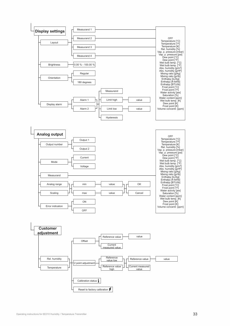
Layout
Display settingsMeasurand 2
Measurand 1
Measurand 3
Measurand 4
Orientation
Regular
180 degrees
Brightness 0.00 % - 100.00 %
Display alarm
Measurand
Limit high
Limit low
Hysteresis
Alarm 1
Alarm 2
value
value
OFFTemperature [°C]Temperature [°F]Temperature [K]Rel. humidity [%]
Vap. p. pressure [mbar]Vap. p. pressure [psi]
Dew point [°C]Dew point [°F]
Wet bulb temp. [°C]Wet bulb temp. [°F]Abs. humidity [g/m³]Abs. humidity [gr/ft³]Mixing ratio [g/kg]Mixing ratio [gr/lb]Enthalpy [kJ/kg]
Enthalpy [ft lbf/lb]Enthalpy [BTU/lb]Frost point [°C]Frost point [°F]
Water activity [aw]Saturation [%]
Water content [ppm]Wet bulb temp. [K]
Dew point [K]Frost point [K]
Volume concentr. [ppm]
Mode
Current
Voltage
ON
Output number
Output 1
Output 2
OFF
Measurand
min
max
value OK
value Cancel
Analog range
Scaling
Error indication
OFFTemperature [°C]Temperature [°F]Temperature [K]Rel. humidity [%]
Vap. p. pressure [mbar]Vap. p. pressure [psi]
Dew point [°C]Dew point [°F]
Wet bulb temp. [°C]Wet bulb temp. [°F]Abs. humidity [g/m³]Abs. humidity [gr/ft³]Mixing ratio [g/kg]Mixing ratio [gr/lb]Enthalpy [kJ/kg]
Enthalpy [ft lbf/lb]Enthalpy [BTU/lb]Frost point [°C]Frost point [°F]
Water activity [aw]Saturation [%]
Water content [ppm]Wet bulb temp. [K]
Dew point [K]Frost point [K]
Volume concentr. [ppm]
Analog output
Customer adjustment
OffsetReference value
Current measured value
Calibration status iReset to factory calibration
2 point adjustment
Reference value low
Reference value high
Rel. humidity
Temperature
value
valueReference value
Current measured value
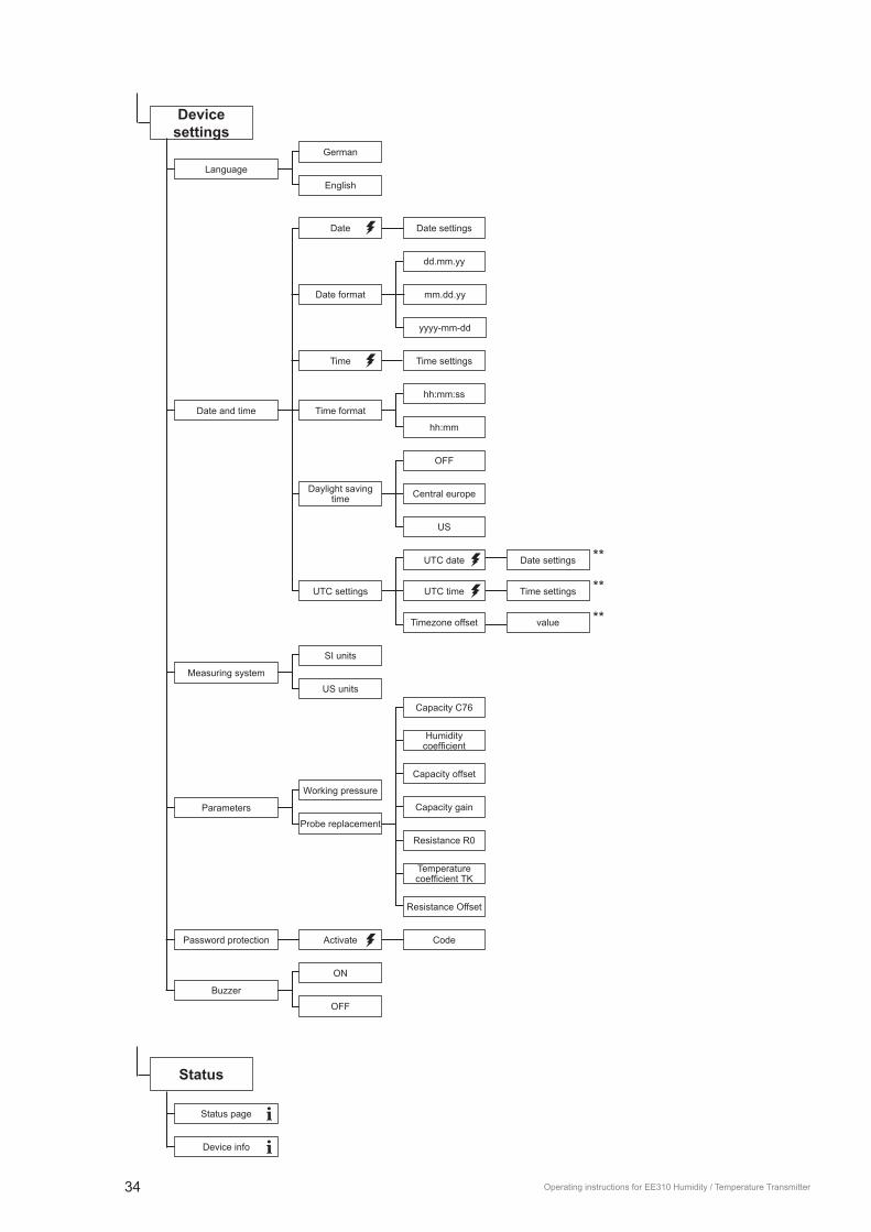
34 Operating instructions for EE310 Humidity / Temperature Transmitter
German
English
Language
Date settings
Time settings
mm.dd.yy
dd.mm.yy
yyyy-mm-dd
Date format
hh:mm:ss
hh:mm
Time format
OFF
US
SI units
US units
Measuring system
Working pressure
Probe replacement
Parameters
Humidity coefficient
Resistance R0
Capacity C76
Capacity gain
Capacity offset
Temperature coefficient.TK
Resistance Offset
Code
Daylight saving time
UTC settings
Timezone offset
UTC date
UTC time
Date settings
Time settings
value
Date and time
Date
Time
Central europe
**
**
**
Device settings
Password protection Activate
ON
OFF
Buzzer
Status page iDevice info i
Status

35Operating instructions for EE310 Humidity / Temperature Transmitter
optional menu (only available with plugged in modules during the start up procedure)
Alarm number
Alarm output
Alarm 2
Alarm 1
Mode
Switch hystersis
Measurand
Switching point
Switching point
Hysteresis
Standard
Inverted
Normal state
Switch window
Measurand
Switching point low
Switching point
Hysteresis
Switching point high
Switching point
Hysteresis
Standard
Inverted
Normal state
Error indication
Standard
Inverted
Normal state
OFFTemperature [°C]Temperature [°F]Temperature [K]Rel. humidity [%]
Vap. p. pressure [mbar]Vap. p. pressure [psi]
Dew point [°C]Dew point [°F]
Wet bulb temp. [°C]Wet bulb temp. [°F]Abs. humidity [g/m³]Abs. humidity [gr/ft³]Mixing ratio [g/kg]Mixing ratio [gr/lb]Enthalpy [kJ/kg]
Enthalpy [ft lbf/lb]Enthalpy [BTU/lb]Frost point [°C]Frost point [°F]
Water activity [aw]Saturation [%]
Water content [ppm]Wet bulb temp. [K]
Dew point [K]Frost point [K]
Volume concentr. [ppm]
Parity
None
Odd
Even
Baudrate value
value
value
Stop bits
Address
Modbus settings
Fig. 32 Configuration menu

COMPANY HEADQUARTERS
E+E ELEKTRONIK Ges.m.b.H. www.epluse.comLangwiesen 7A-4209 EngerwitzdorfAustria Tel: +43 7235 605 0Fax: +43 7235 605 [email protected]
TECHNICAL OFFICES
E+E CHINA www.epluse.cnBEIJINGTel: +86 10 [email protected]: +86 21 [email protected]
E+E GERMANY www.epluse.deTel: +49 6172 13881 [email protected]
E+E FRANCE www.epluse.frTel: +33 4 7472 35 [email protected]
E+E ITALY www.epluse.itTel: +39 02 2707 8636 [email protected]
E+E KOREA www.epluse.co.krTel: +82 31 732 6050 [email protected]
E+E USA www.epluse.comTel: +1 508 530 [email protected]