operation manual · cord can cause fire or electrical shock hazards. regularly check the power cord...
TRANSCRIPT

USF-106TICO-12G TICO codec
USF-TICO-ENC USF-TICO-DEC USF-TICO-ENCDEC USF-TICO-UC
1st Edition - Rev. 4
OPERATION
MANUAL

2
Precautions
Important Safety Warnings
[Power]
Stop
Do not place or drop heavy or sharp-edged objects on the power cord. A damaged cord can cause fire or electrical shock hazards. Regularly check the power cord for excessive wear or damage to avoid possible fire / electrical hazards.
[Circuitry Access]
Stop
Do not touch any parts / circuitry with a high heat factor. Capacitors can retain enough electric charge to cause mild to serious shock, even after the power has been disconnected. Capacitors associated with the power supply are especially hazardous.
Hazard
Unit should not be operated or stored with cover, panels, and / or casing removed. Operating the unit with circuitry exposed could result in electric shock / fire hazards or a unit malfunction.
[Potential Hazards]
Caution
If abnormal odors or noises are noticed coming from the unit, immediately turn the power off and disconnect the power cord to avoid potentially hazardous conditions. If problems similar to the above occur, contact an authorized service representative before attempting to operate the unit again.
[Consumables]
Caution
Consumable items that are used in the unit must be periodically replaced. For further details on which parts are consumables and when they should be replaced, refer to the specifications at the end of the Operation Manual. Since the service life of the consumables varies greatly depending on the environment in which they are used, such items should be replaced at an early date. For details on replacing consumable items, contact your dealer.

3
Upon Receipt
USF-106TICO-12G module cards and their accessories are fully inspected and adjusted prior to
shipment. Check your received items against the packing lists below. Check to ensure no damage has
occurred during shipment. If damage has occurred, or items are missing, inform your supplier
immediately.
The USF-106TICO-12G module is a codec able to compress/decompress between 4K UHD video and
TICO signals. Select Decoder, Encoder or both Encoder and Decoder in advance before factory
shipment.
USF-106TICO-12G Box
ITEM QTY REMARKS
USF-106TICO-12G 1
Front Module
Rear Module
4 screws
DVD-ROM 1
Installation Disc
・USF-106TICO-12G GUI
・Processor Control GUI Launcher
Operation Manuals (PDF)
Software Selection
The USF-106TICO-12G module cards require a software product according to your use of
applications. Select one of the following three options.
Item Application
USF-TICO-ENC Used as Encoder from Uncompressed SDI to TICO
USF-TICO-DEC Used as Decoder from TICO to uncompressed SDI
USF-TICO-ENCDEC Used as both Encoder and Decoder (menu switching)
Up-converter option
USF-TICO-UC Used for encoding from HD to 4K (TICO).
Supported USF Frame
USF-212AS
Trademarks * Microsoft, Windows and Internet Explorer are either registered trademarks or trademarks of Microsoft Corporation in the
United States and/or other countries * Intel Core and Pentium are trademarks of Intel Corporation in the U.S. and/or other countries. * Firefox is a registered trademark of the Mozilla Foundation. * Dolby is a trademark of Dolby Laboratories. * All other trademarks are trademarks or registered trademarks of their respective owners.

4
Table of Contents
1. Prior to Starting ..................................................................................................................................... 6 1-1. Specifications - USF-106TICO-12G Ver.1.1 ............................................................................... 6 1-2. Overview ..................................................................................................................................... 6 1-3. Features ...................................................................................................................................... 7
2. Panel Descriptions ................................................................................................................................ 8 2-1. Front Panel .................................................................................................................................. 8 2-2. Dipswitch Settings ....................................................................................................................... 8 2-3. Rear Panel .................................................................................................................................. 8
3. Connection ........................................................................................................................................... 9 3-1. Basic Configuration ..................................................................................................................... 9 3-2. Video Input and Output .............................................................................................................10
3-2-1. Encoder (SDI Uncompressed >> TICO Compressed) ......................................................10 3-2-2. Decoder (TICO Compressed >> SDI Uncompressed) ......................................................12
4. System Requirements ........................................................................................................................14
5. Installing USF-106TICO-12G GUI ......................................................................................................14
6. Processor Control GUI Launcher .......................................................................................................15 6-1. Installing the GUI Launcher ......................................................................................................15 6-2. Starting the GUI Launcher ........................................................................................................15 6-3. Registering USF-106TICO-12G Modules .................................................................................16 6-4. Changing Module Information ...................................................................................................16 6-5. Deleting a USF-106TICO-12G from the List .............................................................................17
7. USF-106TICO-12G GUI (Windows GUI) ............................................................................................18 7-1. TICO Mode Switching ...............................................................................................................18 7-2. Video Tab ..................................................................................................................................19
7-2-1. Synchronizer ......................................................................................................................20 7-2-2. Reference Select ...............................................................................................................23 7-2-3. Decoder .............................................................................................................................23 7-2-4. Encoder ..............................................................................................................................25 7-2-5. Down Converter .................................................................................................................26 7-2-6. Up Converter (USF-TICO-UC Option) ...............................................................................28 7-2-7. 4K, TICO/3G, HD Ancillary ................................................................................................29 7-2-8. Output Select .....................................................................................................................31 7-2-9. Bypass ...............................................................................................................................31 7-2-10. Video Status.....................................................................................................................32 7-2-11. Ancillary Status ................................................................................................................32
7-3. Audio Tab ..................................................................................................................................33 7-3-1. Input ...................................................................................................................................33 7-3-2. Input Delay x 16 .................................................................................................................34 7-3-3. Sampling Rate Convert ......................................................................................................35 7-3-4. Output Mapping 16 x 16 ....................................................................................................35 7-3-5. Downmix / Monosum / Mute/Test Signal ...........................................................................36 7-3-6. Gain ...................................................................................................................................38 7-3-7. Output Delay ......................................................................................................................38 7-3-8. Output ................................................................................................................................39 7-3-9. Audio System .....................................................................................................................39 7-3-10. Input Status / Output Status .............................................................................................41
7-4. Event Tab ..................................................................................................................................42 7-4-1. Unsaved Menu Settings .....................................................................................................42
7-5. Status Tab .................................................................................................................................42
8. Web GUI .............................................................................................................................................43

5
8-1. Module Information ...................................................................................................................43 8-2. Network .....................................................................................................................................43 8-3. Trap ...........................................................................................................................................44
8-3-1. SNMP Trap Settings ..........................................................................................................44 8-3-2. Downloading MIB Files ......................................................................................................45
8-4. Event Data ................................................................................................................................45 8-5. Gamma Data / Gamut Data ......................................................................................................46
9. SNMP Functions .................................................................................................................................47
10. Specifications and Dimensions ........................................................................................................50 10-1. Unit Specifications ...................................................................................................................50 10-2. External Dimensions ...............................................................................................................51

6
1. Prior to Starting
1-1. Specifications - USF-106TICO-12G Ver.1.1
The USF-106TICO-12G module Version 1 is a limited edition that supports TICO codec basic
operation and audio passing through but does not support color corrector, HDR/WCG, etc.
<Supported functions>
TICO encode and decode
TICO codec supports 3G-SDI Level-A (4:1 compression) and 1.5G-SDI (8:1 compression)
Down-conversion: 4K UHD to HD (1080/59i, 59p)
Up-conversion: HD (1080/59i, 59p) to 4K UHD (USF-TICO-UC option required)
Frame Synchronizer (Reference signal/mode selection and timing adjustment)
Embedded audio pass through and delay adjustment
Control by dedicated GUI
Input/ output of 4K SQD and 3G-SDI Level-B signals
SNMP monitoring
All ancillary data pass through
<Functions/items to be supported in the future>
50Hz family format
Color corrector, process amp., HDR/ WCG conversion function
Remote control by FA-10RU
1-2. Overview
The USF-106TICO-12G module is a codec able to compress/decompress between 4K UHD video
signals. Either encode mode or decode mode is selected at factory shipment. If
USF-TICO-ENCDEC is installed, encoding and decoding can be switched by a user using a menu.
With 4:1 or 8:1 visually lossless compression technology, TICO assures visual quality despite
repeated compression / decompression and small delay (within several tens of lines) in video
processing.
The USF-106TICO-12G module contains a down-converter (4K UHD to 1080i or 1080p) that
enables to simultaneously output de-compressed 4K video and down-converted HD video. When
encoding 4K input, the module simultaneously outputs TICO compressed signals and
down-converted HD signals.
Color corrector (supporting HDR/WCG) (*1) and frame synchronizer (with audio processor) are also
supplied as standard. Up-converter can be added as an option. (USF-TICO-UC option)
The USF-106TICO-12G module contributes reducing the video signal bandwidth and space-saving
on both input and output side systems.
(*1) To be supported in the future.

7
1-3. Features
TICO codec technology enables to transmit 4K/59.94p, 50p video signal over single 3G-SDI
link.
4 ports of 3G-SDI for both input/output are equipped. Available as input/output port of Quad
Link 3G-SDI or 4 inputs and 4 distribution ports of HD/3G-SDI signal.
12G-SDI one-input and two-output ports. 4K signal transmitted via one cable
Supports both 2SI and SQD and Level A and B for 4K 3G-SDI Quad (Additional delay required
for SQD)
Down-conversion function as standard
Outputs HD video from input 4K or decoded 4K video.
Frame Synchronizer function
Able to encode to TICO after stabilizing input signal and supply stable TICO signals (3G-SDI
or 1.5G-SDI) to downstream devices.
Able to supply synchronous 4K signals by decoding TICO signals after FS process.
Audio processing function
Audio delay can be automatically/manually added to compensate the delay difference
between audio and video processing. Gain adjustment, remap, downmix and tone signal
generation are also available.
Color processor function supporting HDR/WCG
In HD-4K up/ down conversion, converting 4K wide color gamut and high dynamic video to
former HD video is available. (To be supported in the future)
Dedicated GUI software control, Web browser control (some functions only), SNMP
monitoring

8
2. Panel Descriptions
2-1. Front Panel
USF-106TICO-12G
No. Name Description
1 Micro SD A micro SD card is installed on the module. Do not remove the micro SD card.
2-2. Dipswitch Settings
IMPORTANT
Note that dipswitch settings should remain unchanged from factory default settings.
If you have accidentally changed the setting, refer to the table below to return to the factory default settings.
Dipswitch Switch No. Setting
DS1 1-8 Off (Do not change)
DS2 1-8 Off (Do not change)
DS7 1-8 Off (Do not change)
2-3. Rear Panel
USF-106TICO-12G 12G/3G/HD-SDI IN1
3G/HD-SDI IO2b2a 2d2c
12G/3G/HD-SDI OUT1a
1b
Item Description
12G/3G/HD-SDI IN1 Used for 12G/3G/HD-SDI input or TICO compressed signal input.
12G/3G/HD-SDI OUT
1a, 1b
Used for 12G/3G/HD-SDI output or TICO compressed signal output.
12G/3G/HD-SDI IN1 active-through possible from 12G/3G/HD-SDI OUT 1a.
3G/HD-SDI IO
2a-2d
Used for 3G/HD-SDI or TICO compressed signal input or output.
If using as input or output for 4K video (Quad Link 3G-SDI), use these ports for Link 1-4 signal.

9
3. Connection
3-1. Basic Configuration
Two USF-106TICO-12G module cards are installed on a USF-212AS frame in this example and the
left card is used as an encoder and the right card as a decoder.
Set input or output for four upper BNC ports. (Default: Input) See Sec. 3-2. “Video Input and Output”
for details.
The USF frame, a control PC (user-supplied) and the FA-10RU (optional remote control unit) are
connected via LAN.
Install the dedicated Windows GUI software to the PC and setup and operate modules. (See Sec. 7.
“USF-106TICO-12G GUI (Windows GUI)” for details.)
The PC Web browser allows you to save/load events (menu settings list) and to import/export
Gamma and Gamut settings files. (See Sec. 8. “Web GUI” for details.)
FA-10RU allows you to setup/operate the modules and save/load events. See the “FA-10RU for
USF-106TICO-12G Operation Manual” for details on FA-10RU connection and operation
(Supported in future)
VIDEO IN THRU
1 21
3G/HD/SDSDI INUSF-1043FS
USF-10 40VEA
1 2
23G/HD/SD SDI OUT
VIDEO OUT3
3
4
4
IN OUT 1/2 3/4 5/67/8
-LTCDIGITAL AUDIO IN
1/2 3/4 5/67/8
-LTCDIGITAL AUDIO OUTIN OUT
3G/HD/SD SDI
3G/HD/SD SDIUSF-1013MUX
USF-101 3DEMUX
1 23G/HD/SD SDI IN
USF-10 43DCC
1 23G/HD/SD SDI OUT
3 4
5 6 7VIDEO OUT
1
VIDEO IN THRU
USF-11 00VEA
8 9
2 3
10
4LAN 1LAN 2
GENLOCK 1
GENLOCK 2
LAN A
SE
R. N
O.
AC1
00-
24
0V
50
/60H
z IN
1AC
10
0-2
40
V 5
0/6
0Hz
IN 2
ALARM USF-212
ANALOG AUDIO
SDI IN1 2 3 4 5
SDI OUT
USF-1 08ADA
USF-10 53DDAUSF-106UDC-12G
3G/H D/SD-SDI IO
2a 2b 2c 2d
12G/ 3G/HD/ SD-SDI OUT
12G/3G/HD /SD-SD I IN
1a
1b
USF-106UDC-12G
3G/H D/SD-SDI IO
2a 2b 2c 2d
12G/ 3G/HD/ SD-SDI OUT
12G/3G/HD /SD-SD I IN
1a
1b
USF-212AS Rear Panel
Windows GUI Software
Web browser
AC100-240V 50/60Hz IN
GPI3GPI2GPI1TO MU
(10/100/1000BASE-T)
Ethernet hub
Reference Signal
4K Video
4K Video
75Ω Termination
TO MU 192.168.0.100 (255.255.255.0)
LAN port 192.168.0.53 (255.255.255.0)
Setup and operation (Windows GUI software) Save/load events (Web browser)
Se
tup
an
d o
pe
ratio
n
Sa
ve
/lo
ad e
ve
nts
Selectable Inputs/outputs
LAN1 192.168.0.10 (255.255.255.0)
FA-10RU (Optional Remote Control Unit)
USF-106TICO-12G
TICO Signal
TICO Signal

10
3-2. Video Input and Output
3-2-1. Encoder (SDI Uncompressed >> TICO Compressed)
If using SDI I/O 2a-2d as input (*1)
I/O Configuration: USF-106TICO-12G with USF-TICO-ENC option
Input video Input port (*2) SDI OUT 1a, 1b
output video [Video] > [Output Select]
menu settings
HD(*5) SDI IN 1
SDI I/O 2a-2d
TICO compressed signal Out 1a/1b: TICO
Down-converted HD Out 1a/1b: DC HD
4K (12G Single)
SDI IN 1 TICO compressed signal Out 1a/1b: TICO
Down-converted HD Out 1a/1b: DC HD
4K (3G Quad)
SDI IN1
SDI I/O 2b-2d (*3)
TICO compressed signal Out 1a/1b: TICO
Down-converted HD Out 1a/1b: DC HD
4K (3G Quad)
SDI I/O 2a-2d (*4) TICO compressed signal Out 1a/1b: TICO
Down-converted HD Out 1a/1b: DC HD
(*1) Select Input under [Video > Synchronizer > SDI 2 IO Direction]. (p. 20) (*2) Select Input under [Video > Synchronizer > Input Source > Source]. (p. 20) (*3) Select IN1 under [Video > Synchronizer > Input Source > Source]. (p. 20) (*4) Select IO 2a under [Video > Synchronizer > Input Source > Source]. (p. 20) (*5) USF-TICO-UC required
Input: SDI IN1
Output: SDI OUT 1a, 1b
USF-106TICO-12G 12G/3G/HD-SDI IN1
3G/HD-SDI IO2b2a 2d2c
12G/3G/HD-SDI OUT1a
1b
Input: SDI IO 2a-2d
Output: SDI OUT 1a, 1b
USF-106TICO-12G 12G/3G/HD-SDI IN1
3G/HD-SDI IO2b2a 2d2c
12G/3G/HD-SDI OUT1a
1b
TICO compressed signal, HD or loop through out of SDI IN
TICO compressed signal
or HD
HD (USF-TICO-UC option) or 4K (3G Quad)
4K (12G)
or HD
TICO compressed signal, HD
or loop through out of SDI IN
TICO compressed signal
or HD

11
Input: SDI IN1, SDI IO 2b-2d
Output: SDI OUT 1a, 1b
USF-106TICO-12G 12G/3G/HD-SDI IN1
3G/HD-SDI IO2b2a 2d2c
12G/3G/HD-SDI OUT1a
1b
If using SDI I/O 2a-2d as output (*1)
I/O Configuration: USF-106TICO-12G with USF-TICO-ENC option
Input video Input port
(*2) SDI OUT 1a, 1b
output video SDI I/O 2a-2d output video
[Video] > [Output Select]
menu settings
HD (*3)
SDI IN1
TICO compressed signal
TICO compressed signal
Out 1a/1b: TICO
IO 2a-2d: TICO
Down-converted HD
Down-converted HD
Out 1a/1b: D/C HD
IO 2a-2d: D/C HD
4K (12G Single)
TICO compressed signal
TICO compressed signal
Out 1a/1b: TICO
IO 2a-2d: TICO
Down-converted HD
Down-converted HD
Out 1a/1b: D/C HD
IO 2a-2d: D/C HD
(*1) Select Output under [Video > Synchronizer > SDI 2 IO Direction]. (p. 20) (*2) Select IN1 under [Video > Synchronizer > Input Source > Source]. (p. 20) (*3) USF-TICO-UC required
Input: SDI IN1
Output: SDI OUT 1a, 1b
SDI I/O 2a, 2b, 2c, 2d
USF-106TICO-12G 12G/3G/HD-SDI IN1
3G/HD-SDI IO2b2a 2d2c
12G/3G/HD-SDI OUT1a
1b
4K (12G) or HD
TICO compressed signal
or HD
TICO compressed signal
or HD (4 distributions)
TICO compressed signal, HD
or loop through out of SDI IN
4K (3G Quad Link2-4) TICO compressed signal
or HD
4K (3G Quad Link1) TICO compressed signal, HD
or loop through out of SDI IN
12
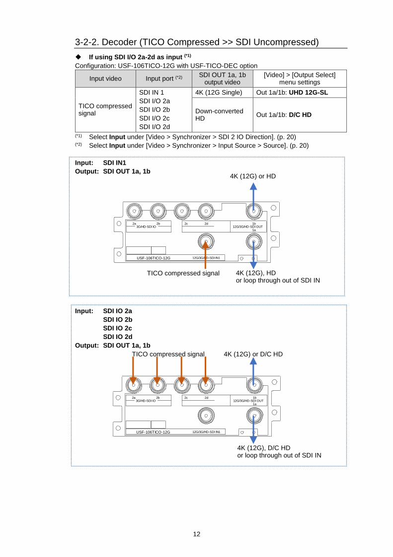
3-2-2. Decoder (TICO Compressed >> SDI Uncompressed)
If using SDI I/O 2a-2d as input (*1)
Configuration: USF-106TICO-12G with USF-TICO-DEC option
Input video Input port (*2) SDI OUT 1a, 1b
output video [Video] > [Output Select]
menu settings
TICO compressed signal
SDI IN 1
SDI I/O 2a
SDI I/O 2b
SDI I/O 2c
SDI I/O 2d
4K (12G Single) Out 1a/1b: UHD 12G-SL
Down-converted HD
Out 1a/1b: D/C HD
(*1) Select Input under [Video > Synchronizer > SDI 2 IO Direction]. (p. 20) (*2) Select Input under [Video > Synchronizer > Input Source > Source]. (p. 20)
Input: SDI IN1
Output: SDI OUT 1a, 1b
USF-106TICO-12G 12G/3G/HD-SDI IN1
3G/HD-SDI IO2b2a 2d2c
12G/3G/HD-SDI OUT1a
1b
Input: SDI IO 2a
SDI IO 2b
SDI IO 2c
SDI IO 2d
Output: SDI OUT 1a, 1b
USF-106TICO-12G 12G/3G/HD-SDI IN1
3G/HD-SDI IO2b2a 2d2c
12G/3G/HD-SDI OUT1a
1b
TICO compressed signal 4K (12G), HD or loop through out of SDI IN
4K (12G) or HD
TICO compressed signal
4K (12G), D/C HD or loop through out of SDI IN
4K (12G) or D/C HD

13
If using SDI I/O 2a-2d as output (*1)
Configuration: USF-106TICO-12G with USF-TICO-DEC option
Input video Input
port (*2) SDI OUT 1a, 1b
output video SDI OUT 2a-2d
output video [Video] > [Output Select]
menu settings
TICO compressed signal
SDI IN1
4K (12G Single) 4K (3G Quad) Link1-4
Out 1a/1b: UHD 12G-SL IO 2a: UHD 3G-QL (L1) | IO 2d: UHD 3G-QL (L4)
4K (3G Quad) Link1
4K (3G Quad) Link1-4
Out 1a/1b: UHD 3G-QL (L1) IO 2a: UHD 3G-QL (L1) | IO 2d: UHD 3G-QL (L4)
Down-converted HD
Down-converted HD
Out 1a/1b: D/C HD
IO 2a-2d: D/C HD
(*1) Select Output under [Video > Synchronizer > SDI 2 IO Direction]. (p. 20) (*2) Select IN1 under [Video > Synchronizer > Input Source > Source]. (p. 20)
Input: SDI IN1
Output: SDI OUT 1a-1b, SDI IO 2a-2d
USF-106TICO-12G 12G/3G/HD-SDI IN1
3G/HD-SDI IO2b2a 2d2c
12G/3G/HD-SDI OUT1a
1b
TICO compressed signal 4K (12G), HD, 4K (3G Quad Link1), or loop through out of SDI IN
4K (12G), HD
or 3G Quad Link1
4K (3G Quad Link 1-4)
or HD (4 distributions)
14
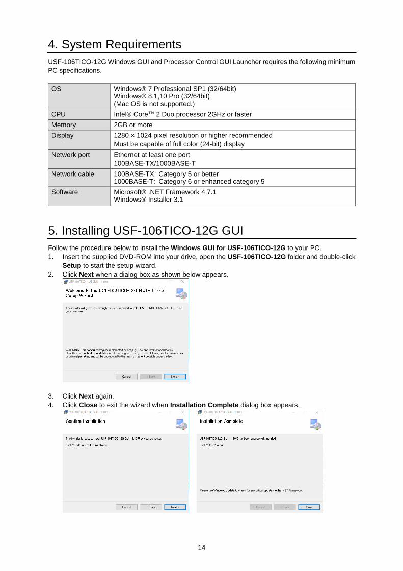
4. System Requirements
USF-106TICO-12G Windows GUI and Processor Control GUI Launcher requires the following minimum
PC specifications.
OS Windows® 7 Professional SP1 (32/64bit) Windows® 8.1,10 Pro (32/64bit) (Mac OS is not supported.)
CPU Intel® Core™ 2 Duo processor 2GHz or faster
Memory 2GB or more
Display 1280 × 1024 pixel resolution or higher recommended
Must be capable of full color (24-bit) display
Network port Ethernet at least one port
100BASE-TX/1000BASE-T
Network cable 100BASE-TX: Category 5 or better 1000BASE-T: Category 6 or enhanced category 5
Software Microsoft® .NET Framework 4.7.1 Windows® Installer 3.1
5. Installing USF-106TICO-12G GUI
Follow the procedure below to install the Windows GUI for USF-106TICO-12G to your PC.
1. Insert the supplied DVD-ROM into your drive, open the USF-106TICO-12G folder and double-click
Setup to start the setup wizard.
2. Click Next when a dialog box as shown below appears.
3. Click Next again.
4. Click Close to exit the wizard when Installation Complete dialog box appears.

15
6. Processor Control GUI Launcher
Processor Control GUI Launcher allows you to connect multiple USF-106TICO-12G module cards and
switch the Windows GUI control card within them. Install the Processor Control GUI Launcher into your
computer and register USF-106TICO-12G module cards.
6-1. Installing the GUI Launcher
1. Open the Processor Control GUI Launcher folder in the supplied DVD-ROM and
double-click the Setup file to start the setup wizard.
2. When a dialog box as shown below appears, click Next.
3. Click Next again.
4. Click Close to exit the wizard when Installation Complete dialog box appears.
6-2. Starting the GUI Launcher
An icon is created on the desktop when the GUI Launcher is installed.
Double-click the icon to start the GUI Launcher.
The following Launcher screen appears when the GUI Launcher starts.

16
6-3. Registering USF-106TICO-12G Modules
1. Click Add Unit to open the Add Unit window.
2. Enter the IP address and module Name (arbitrary name for identification) and click OK.
* When connecting via the USF frame LAN A port, check the NAT Connection checkbox and
specify HTTP Port and Control Port.
3. The USF-106TICO-12G is registered, displayed in the Launcher screen list and automatically
connected to the Launcher.
The Status field shows the following status messages.
Status message Meaning
Searching Searching the target device.
Connected Connected with the target device.
Disconnected Disconnected with the target device.
Error Unable to control the target device from Processor Control GUI Launcher.
4. When the connection is established, the Status display changes from Searching to
Connected.
5. Select a connected module (with Connected state) in the list and double-click it to start the
GUI. (Install Windows GUI software onto the computer beforehand.)
6-4. Changing Module Information
1. Right-click a USF-106TICO-12G in the list to display the context menu.
2. Click Edit to display the Edit Unit dialog box and change the IP Address and/or Name.
* Note that changing the IP address immediately starts searching for the module with the new IP
address.

17
6-5. Deleting a USF-106TICO-12G from the List
1. To delete a USF-106TICO-12G from the list, click Disconnect to disconnect all modules
connection.
2. Right-click on the USF-106TICO-12G to display the context menu.
3. Click Remove to remove the module entry.

18
7. USF-106TICO-12G GUI (Windows GUI)
Launch the Windows GUI using the Processor Control GUI Launcher.
Double-click a connected USF-106TICO-12G module in the registration list to display the main window.
Its menu layout is different according to installed software options. (Encoder mode main window is as
shown below.)
The main window consists of four tabs that are Video, Audio, Event and Status.
Video tab: Displays Video Block diagram that allows you to set video processing settings.
Audio tab: Displays Audio Block diagram that allows you to set audio processing settings.
Event tab: Allows you to save/load setting values.
Status tab: Information of the connected module is displayed.
7-1. TICO Mode Switching
Selecting the TICO mode from the menu bar allows you to switch TICO operation modes.
Item Setting Description
TICO Mode
Decoder DC Operating mode is to decompress the TICO signal to 4K signal. *Requires USF-TICO-DEC option.
Encoder DC Operating mode is to compress the 4K signal to TICO signal. *Requires USF-TICO-ENC option.
Encoder UC Operating mode is to up convert 2K signal to 4K signal then compress it to TICO signal. *Requires USF-TICO-ENC and USF-TICO-UC option.

19
7-2. Video Tab
Click the Video tab in the GUI screen to display the Video Block diagram as shown below.
Click a block according to the processing order to open a settings window and perform settings
Encoder Mode
Decoder Mode
Block name Ref. Block name Ref.
Synchronizer 7-2-1 4K, TICO/3G, HD Ancillary 7-2-7
Reference Select 7-2-2 Output Select 7-2-8
Decoder 7-2-3 Bypass 7-2-9
Encoder 7-2-4 Video Status 7-2-10
Down Converter 7-2-5 Ancillary Status 7-2-11
Up Converter (*1) 7-2-6
(*1) USF-TICO-UC required

20
7-2-1. Synchronizer
Click Synchronizer in the Video Block to display the menu screen as shown below.
Item Default Setting Description
SDI 2 IO Direction In Encoder Mode - Input
In Decoder Mode - Output
Input Output
Select Input or Output for SDI IO 2a-2d (four BNC ports).
Input Source
Item Default Setting Description
Link(UHD) Single Link Single Link Quad Link
Selects a 4K UHD SDI signal format.
Source IN 1
IN 1 IO 2a IO 2b IO 2c IO 2d
Selects an input signal.
Terminal Assign - - Displays input terminals assignment status.
Format
Item Default Setting Description
Format Auto Detect Auto Detect
Manual
Selects the Synchronizer output format.
Auto Detect: The Synchronizer input signal format.
Manual: Signal format specified below.
If Format Detection is set to Manual, specify the format using the following settings.
Standard 1080 1080 2160
Selects the vertical image resolution.
Horizontal Size 1920/3840 1920/3840 Displays the horizontal image resolution. (Not settable)
Frame Rate 59.94i 59.94p 59.94i
Selects the frame/ field rate.
Division
(UHD) Follow Input
Follow Input SQD 2SI
Selects the SDI image division method.
Level Follow Input Follow Input Level-A Level-B
Selects the SDI mapping level.
Synchronized Format
- - Displays the synchronizer output format.

21
Video Loss
Item Default Setting Description
Source Back Color (Link)
Back Color(Link)
Back Color(Separate)
Auto Freeze
Output Mute
Selects the output mode for input signal loss.
Back Color(Link): Outputs a monochrome (set under Back Color below) video.
Back Color(Separate): Outputs the input video, displaying monochrome (set under Back Color below) for the lost part.
Auto Freeze: Freezes and outputs the last normal video.
Output Mute: Outputs no video signal so that the USF-106TICO-12G downstream device can detect video loss.
See the table on the next page for 4K Quad Link 3G input.
Loss Mode: Partial loss of 4K Quad Link 3G input
4K input Video Loss Source
Setting Output Video in Input Partial Loss
2SI
Back Color(Link)
Output Mute
Compensates the loss and restores the whole input image,
maintaining its appearance.
Back Color(Separate) Replaces lost parts with back color to restore the whole
input image. The image is displayed with lower luminance.
Auto Freeze Freezes and outputs the last normal video.
SQD
Back Color(Link) Outputs a back color video.
Back Color(Separate)
Output Mute
Outputs the input video displaying back color for the lost
part.
Auto Freeze Freezes and outputs the last normal video.
Synchronizer Mode
Item Default Setting Description
Synchronizer Mode
Frame
Frame
Line
AVDL
Line (Min)
Selects the reference mode.
Use “Frame” if genlock input and video input signals are not synchronized. When adjusting video signals, the reference point (H:0, V:0) can be offset under Timing settings. If the reference point is changed, adjustable ranges are also changed accordingly.
See the chart below for details on adjustable ranges.
Frame: Aligns input video signals using frame memory.
Line: Aligns input video signals using 1H memory.
AVDL: Aligns input video signals using both 1H and frame memory.
Line (Min): Aligns input video signals using 1H memory and outputs signals with minimum delay.

22
Adjust Timing
Item Default Setting Description
H Timing 0 Clock -2750 to 2750 (1080/Level B)
-1375 to 1375 (1080)
System sync timing can be shifted from the reference source. To do this, set the horizontal and vertical offsets. V Timing 0 Line -563 to 563
Sync Delay Displays the video process delay amount from Synchronizer input to adjustment by Adjust Timing.
Video Freeze
Item Default Setting Description
Freeze Off Off On
Turns freeze ON/OFF.
Mode Frame Frame Odd Even
Sets the freeze mode. This setting is ignored if progressive/no signal is input to FS.
* Operates with Even mode regardless of the present mode selection when input signal is Level B.
Signal Synchronization and Signal Timing Control
Bars in the figure below represent adjustable timing ranges for reference modes.
If timing difference of input signal exceeds the range, one frame delay may be added to the
signal or output image may be shifted vertically.
-6H -5H -4H -3H -2H -1H 0H
Frame adjust range: -2.0H (for 4K/HD Single Link signals) (-2.0H or advanced signals, no frame delay. Otherwise, a frame delay may occur.) -4.0H (for 4K Dual/Quad Link signals) AVDL adjust range: -6.0H to -0.5H (A frame delay may occur, if input signals exceed the range) Line adjust range: -1.5H to -0.5H (Output images may be shifted vertically, if input signals exceed the range.) Line (MIN) adjust range: -(1H+700clk) to -700clk (Output images may be shifted vertically, if input signals exceed the range.) Synchronizer output timing: Timing H:0, V:0 (The timing reference point can be offset. See previous page Adjust Timing.)

23
7-2-2. Reference Select
Click Reference Select in the Video Block to display the menu screen as shown below.
Item Default Setting Description
Reference Select
GENLOCK IN
GENLOCK IN
Input Lock
Free Run
Selects a reference source.
GENLOCK IN: Uses a reference signal (BB or Tri-level Sync.) input to the USF frame.
Input Lock: Uses the SDI signal selected under Input Source.
Free Run: Uses the internal sync signal generator.
Genlock Select GENLOCK 1 GENLOCK 1
GENLOCK 2
Selects a reference source from two genlock signals input to the USF frame.
7-2-3. Decoder
Click Decoder in the Video Block to display the menu screen as shown below.
Decoder
Output Format
Item Default Setting Description
Division (UHD)
2SI SQD 2SI
Select a division for 4K output.
Level Level-A Level-A Level-B
Select a level for 3G-SDI output.
* Set 2SI Level-A for 12G-SDI output.

24
Decoder
Item Display Description
Profile
NotTICO
Profile 1 Profile 2
Displays the TICO signal status input to the Decoder.
Compress Mode
TICO 4:1
TICO 8:1
Displays the TICO signal compress mode input to the Decoder.
Error Count - Displays decoding error count.
Resets the error count by pressing the Reset button.
Restart -
Restarts decoding when the Decoder stops abnormally. Normally do not use. When a malfunction occurs in the Decoder and it cannot be recovered, press this button to initialize and restart the Decoder.
Delay
Item Default Setting Description
Delay 0 0 - 8 Sets delay from 1 - 8 frames. If adding no delay, set to 0.
Converter Delay
Frame Frame Minimum Adjustable
Sets converter output timing.
Frame: Outputs with the delay amount set under Delay.
Minimum: Outputs with minimum delay.
Adjustable: Output with the delay amount adjusted below. Adjustments should be on the bases of the delay set under Delay.
The following settings are enabled when Adjustable is selected for Converter Delay.
H Timing 0 Clock -2750 to 2750 Clock Fine tunes horizontal delay of the video.
V Timing 0 Line -563 to 563 Line Fine tunes vertical delay of the video.
Fine-tuned video delay amounts are shown on Converter Delay in ms or ns.

25
7-2-4. Encoder
Click Encoder in the Video Block to display the menu screen as shown below.
Encoder
Settable Item
Item Default Setting Description
Compress Mode
TICO 4:1 (3G)
TICO 4:1(3G)
TICO 8:1(1.5G)
Selects TICO signal compression ratio and output frame rate.
TICO 4:1(3G): Outputs 4:1 compressed TICO signal in 59.94p (3G-SDI).
TICO 8:1(1.5G): Outputs 8:1 compressed TICO signal in 59.94i (1.5G-SDI).
Status Items
Item Display Description
Status Error
Running Displays the Encoder operating condition.
Error Count ― Displays error count of the Encoder.
Resets error count by pressing the Reset button.
Restart ―
Restarts encoding when the Encoder stops abnormally. Normally do not use. When a malfunction occurs in the Encoder and cannot be recovered, press this button to initialize and restart the Encoder.
Delay
See Sec. 7-2-3. “Decoder” for details.
Fine-tuned video delay amounts are shown on Converter Delay in ms.

26
7-2-5. Down Converter
Click Down Converter in the Video Block to display the menu screen as shown below.
Format Convert
Item Default Settings Description
Frame Rate 59.94i 59.94p 59.94i
Select a frame rate.
Level Level-A Level-A Level-B
Select level for 3G-SDI output.
D/C Phase
In Encoder Mode - Same As Enc
In Decoder Mode - Same As Dec.
Same As Enc
Same As Dec
Minimum
Same As Enc: Same as ENCODER output.*1
Same As Dec: Same as DECODER output. *2
Minimum: Outputs with minimum delay
*1 Displayed under Encoder Mode. *2 Displayed under Decoder Mode
Filter
Horizontal Anti Alias, Vertical Anti Alias
Item Default Setting Description
Mode Auto Auto
Manual
Auto: Sets Frequency and Level automatically.
Manual: Sets Frequency manually.
Frequency H: 0.500
V: 0.250 0.125 – 0.500
Sets cutoff frequency.
* Settable when Mode is set to Manual.

27
Level H: 100%
V: 100%
0 (Off ) – 100%
Sets the original video mixing level.
* Settable when Mode is set to Auto and Manual.
Horizontal Enhancer, Vertical Enhancer
Item Default Setting Description
Enhance Disable Disable
Enable
Enables or disables Horizontal or Vertical Enhancer.
High 1 0 – 10 Sets the horizontal enhance level in the range from 0.29 to 0.4 of the sampling frequency.
Middle 1 0 – 10 Sets the horizontal enhance level in the range from 0.17 to 0.29 of the sampling frequency.
Low 1 0 – 10 Sets the horizontal enhance level in the range from 0.03 to 0.17 of the sampling frequency.
Noise Reducer
Item Default Setting Description
Noise Reducer
Disable Disable Enable
Enables or disables Noise Reducer in up/down-conversion to/from 4K.
Red 8 1 - 16 Sets the noise reduction level in RGB for low luminance side (darker parts) caused by a camera or other apparatus. This reducer is ineffective for noises in high luminance side (brighter parts) and block noises from picture compression. The stronger (the bigger amount) the filtering level of Red, Green or Blue, the more the high-frequency components in video images are attenuated.
Green 8 1 - 16
Blue 8 1 - 16

28
7-2-6. Up Converter (USF-TICO-UC Option)
Click Up Converter in the Video Block to display the menu screen as shown below.
Format Convert
Item Default Setting Description
Motion Sense
Adaptive
Adaptive
Field
Frame(Odd 1st)
Frame(Even 1st)
Field: Generates a progressive scan image from one field of an interlaced scan image. The created image has no distortions caused by motion correction, but vertical resolution will be reduced. Adaptive: Detects whether there is motion or no motion in the scene, and generates an optimal progressive scan image. Frame(Odd 1st): Generates a progressive scan image from two fields (odd/even) of an interlaced scan image. Suitable for the progressive segment frame input of progressive scan signals. Frame(Even 1st): Generates a progressive scan image from two fields (even/odd) of an interlaced scan image.
Filter
See Sec. 7-2-5. “Down Converter” for details on settings.
Other
Directional Interpolation (4K up conversion)
Item Default Setting Description
Enable/ Disable
Disable Disable
Enable
Select Enable or Disable for Edge Detection in resize interpolation.
Edge Detect
5 0 - 10
Sets Edge Detection sensitivity for resize interpolation.
The smaller the set value is, the sensitivity is increased and directional interpolation range is enlarged.
29
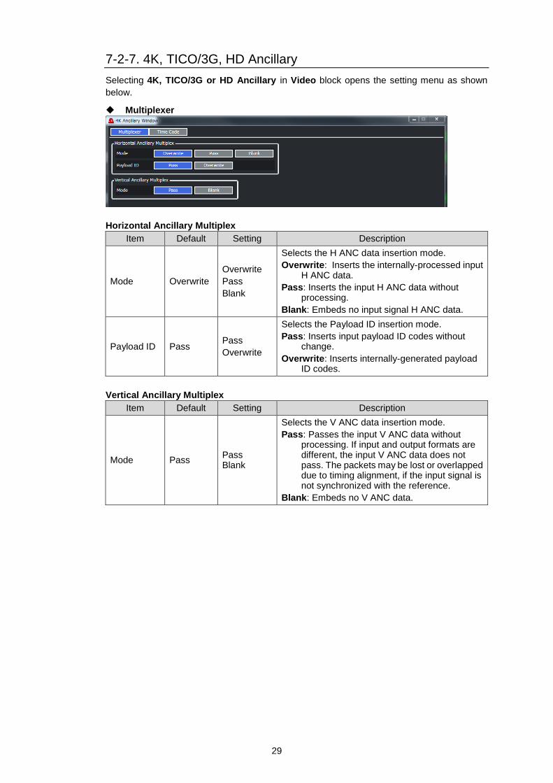
7-2-7. 4K, TICO/3G, HD Ancillary
Selecting 4K, TICO/3G or HD Ancillary in Video block opens the setting menu as shown
below.
Multiplexer
Horizontal Ancillary Multiplex
Item Default Setting Description
Mode Overwrite
Overwrite
Pass
Blank
Selects the H ANC data insertion mode.
Overwrite: Inserts the internally-processed input H ANC data.
Pass: Inserts the input H ANC data without processing.
Blank: Embeds no input signal H ANC data.
Payload ID Pass Pass
Overwrite
Selects the Payload ID insertion mode.
Pass: Inserts input payload ID codes without change.
Overwrite: Inserts internally-generated payload ID codes.
Vertical Ancillary Multiplex
Item Default Setting Description
Mode Pass Pass Blank
Selects the V ANC data insertion mode.
Pass: Passes the input V ANC data without processing. If input and output formats are different, the input V ANC data does not pass. The packets may be lost or overlapped due to timing alignment, if the input signal is not synchronized with the reference.
Blank: Embeds no V ANC data.
30
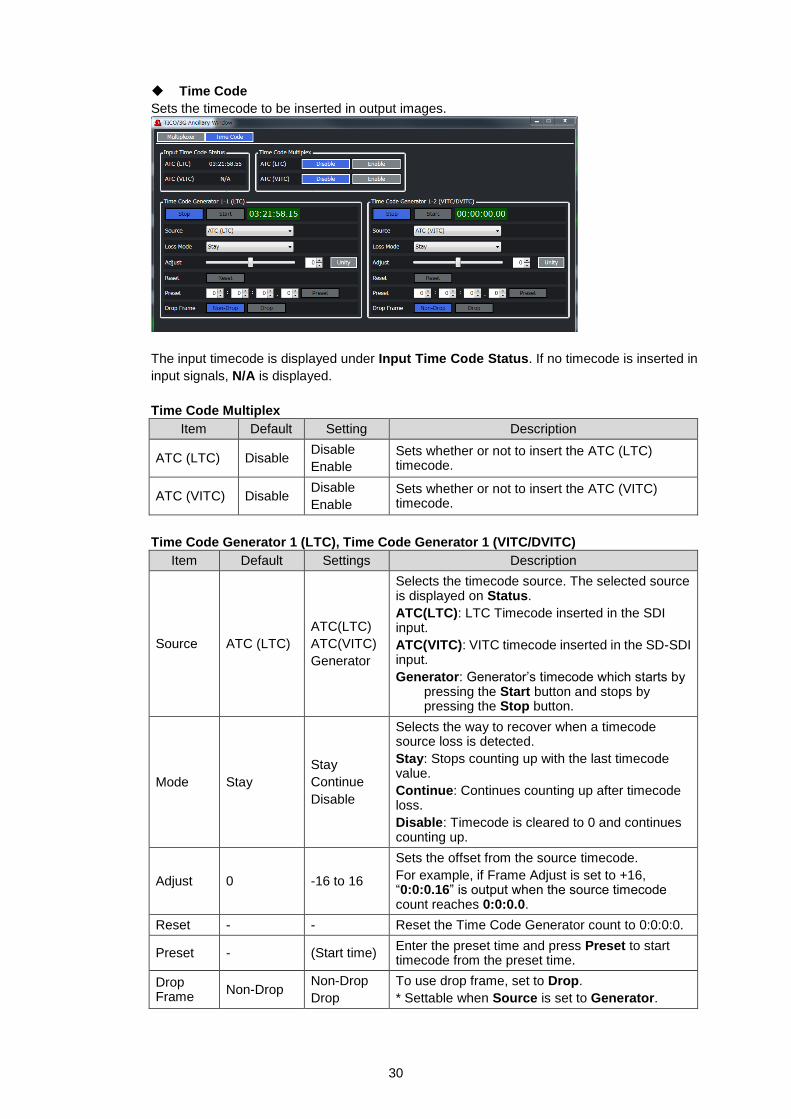
Time Code
Sets the timecode to be inserted in output images.
The input timecode is displayed under Input Time Code Status. If no timecode is inserted in
input signals, N/A is displayed.
Time Code Multiplex
Item Default Setting Description
ATC (LTC) Disable Disable
Enable
Sets whether or not to insert the ATC (LTC) timecode.
ATC (VITC) Disable Disable
Enable
Sets whether or not to insert the ATC (VITC) timecode.
Time Code Generator 1 (LTC), Time Code Generator 1 (VITC/DVITC)
Item Default Settings Description
Source ATC (LTC)
ATC(LTC)
ATC(VITC)
Generator
Selects the timecode source. The selected source is displayed on Status.
ATC(LTC): LTC Timecode inserted in the SDI input.
ATC(VITC): VITC timecode inserted in the SD-SDI input.
Generator: Generator’s timecode which starts by pressing the Start button and stops by pressing the Stop button.
Mode Stay
Stay
Continue
Disable
Selects the way to recover when a timecode source loss is detected.
Stay: Stops counting up with the last timecode value.
Continue: Continues counting up after timecode loss.
Disable: Timecode is cleared to 0 and continues counting up.
Adjust 0 -16 to 16
Sets the offset from the source timecode.
For example, if Frame Adjust is set to +16, “0:0:0.16” is output when the source timecode count reaches 0:0:0.0.
Reset - - Reset the Time Code Generator count to 0:0:0:0.
Preset - (Start time) Enter the preset time and press Preset to start timecode from the preset time.
Drop Frame
Non-Drop Non-Drop
Drop
To use drop frame, set to Drop.
* Settable when Source is set to Generator.

31
7-2-8. Output Select
Selecting Output Select in Video block opens the setting menu as shown below.
Encoder and Decoder setting values are different.
Encoder Mode
Item Default Settings Description
OUT 1a/1b TICO D/C HD
TICO
D/C HD: Outputs 4K down-converted HD signal.
TICO: Outputs TICO compressed signal.
IO 2a (OUT) - IO 2d (OUT)
TICO DC HD
TICO
DC HD: Outputs decoded 4K signal.
TICO: Outputs TICO compressed signal.
Decoder Mode
Item Default Settings Description
OUT 1a/1b UHD 12G-SL
UHD 12G-SL
UHD 3G-QL (L1)
DC HD
UHD 12G-SL: Outputs 4K in 12G Single.
UHD 3G-QL (L1): Outputs 4K in 3G Quad.
DC HD: Outputs 4K down-converted HD.
IO 2a (OUT) - IO 2d (OUT)
UHD 3G-QL (L*) UHD 3G-QL (L*)
DC HD
UHD 3G-QL (L*): Outputs 4K in 3G Quad.
DC HD: Outputs 4K down-converted HD.
7-2-9. Bypass
Selecting Bypass in Video block opens the setting menu as shown below.
Item Default Settings Description
IN 1 - OUT 1a Operate Active Through
Operate
Active Through: Passes input signal (IN1) through to output (OUT 1a) without processing.
Operate: Processes input signals.
32
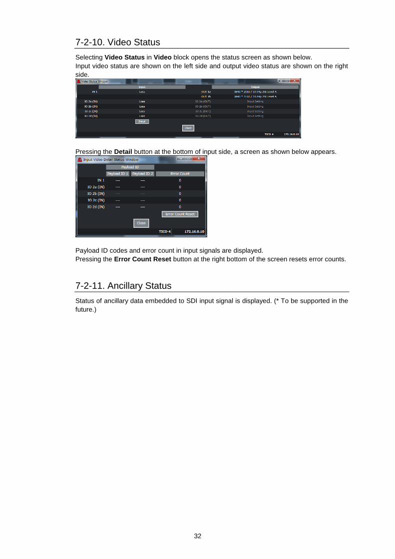
7-2-10. Video Status
Selecting Video Status in Video block opens the status screen as shown below.
Input video status are shown on the left side and output video status are shown on the right
side.
Pressing the Detail button at the bottom of input side, a screen as shown below appears.
Payload ID codes and error count in input signals are displayed.
Pressing the Error Count Reset button at the right bottom of the screen resets error counts.
7-2-11. Ancillary Status
Status of ancillary data embedded to SDI input signal is displayed. (* To be supported in the
future.)

33
7-3. Audio Tab
Click the Audio tab in the GUI screen to display the Audio Block diagram as shown below.
Click a block according to the processing order to open a settings menu screen and set settings
Block Name Ref. Block Name Ref.
Input 7-3-1 Gain 7-3-6
Input Delay x 16 7-3-2 Output Delay 7-3-7
Sampling Rate Convert 7-3-3 Output 7-3-8
Output Mapping 16 x 16 7-3-4 Audio System 7-3-9
Downmix / Monosum / Mute/Test Signal 7-3-5 Input Status / Output Status 7-3-10
7-3-1. Input
Selecting Input in Audio block opens the menu screen as shown below.
The SDI input on which audio channels were embedded are displayed in Input Source.

34
Embedded Audio Demultiplexer
Item Default Setting Description
Group Alignment
Disable Enable
Disable
Selects whether to perform auto phase adjustment among each embedded audio group.
Enable: Performs auto adjustment.
Disable: Performs no auto adjustment (Normal setting).
Demultiplex Clock
Auto
Auto
Sync SDI
Audio Clock
Selects the audio de-embedding method for HD-SDI input.
Auto: Uses the audio clock phase data in HD-SDI input to de-embed audio from SDI. Synchronous or asynchronous de-embedding available for respective four groups. When audio phase data is incorrect or de-embedded audio has noticeable jitter, audio channels in all groups are automatically de-embed synchronously.
Sync SDI: Synchronously de-embeds audio channels in all groups without using the audio clock phase data.
Audio Clock: Uses the audio clock phase data in the HD-SDI input to de-embed audio from SDI for respective group (Synchronous or asynchronous de-embedding).
Audio Polarity
Item Default Setting Description
Ch.1-16 Normal Normal
Invert
Normal: Selects the (odd number) channel polarity.
Invert: Inverts the audio channel polarity.
7-3-2. Input Delay x 16
Selecting Input Delay x 16 in Audio block opens the menu screen as shown below.
Item Default Setting Description
Adjust Video Delay - - Pressing Set adds the displayed delay amount at the left side of the button to Master Delay.
Master 1 ms 1-1000 ms Sets the delay offset for all 16 channels.
Ch.1-16 1 ms 1-1000 ms
Each channel delay amount (sum of each delay and Master delay) is displayed. To adjust each channel delay, use the slide bar.

35
7-3-3. Sampling Rate Convert
Selecting Sampling Rate Convert in Audio block opens the menu screen as shown below.
Item Default Setting Description
Ch.1/2-
Ch.15/16 Auto
Auto
SRC Input
Bypass
Sets the SRC processing mode for each channel pair.
Auto: PCM audio is processed by the SRC. Non-PCM audio is not processed by the SRC.
By-pass: Avoids the SRC. Use By-pass for non-PCM audio. Note that to embed non-PCM audio to the SDI output, audio group clock should be properly selected under Multiplex Clock (see Sec. 7-3-8. “Output”).
SRC In: Both PCM and non-PCM audio is processed by SRC. This is useful for irregular audio such as PCM audio content with non-PCM metadata. Note that SRC-processed audio may not be played properly if it is a true non-PCM audio signal.
7-3-4. Output Mapping 16 x 16
Selecting Output Mapping 16 x 16 in Audio block opens the menu screen as shown below.
This menu allows you to remap audio channels and to assign created down-mixed,
mono-summed, or test tone audio to output channels.
Item Default Setting Description
Ch.1-16 Embedded Ch.1-16
Embedded Ch. 1-16
500Hz Tone
1kHz Tone
Silence
Downmix L
Downmix R
Mono Sum Ch. 1-8
Selects an audio source for each channel.
Embedded Ch.1-16: 16 audio channels de-embedded from the SDI input.
1kHz, 500Hz Tone: Audio test signals
Silence: Mute signal
Downmix L/R: Downmixed audio channels
Mono Sum Ch1-8: Mono-summed audio channels

36
7-3-5. Downmix / Monosum / Mute/Test Signal
Selecting Downmix/ Monosum/ Mute/Test Signal in Audio block opens the menu screen as
shown below.
Downmix
Downmix Mode
Item Default Setting Description
Mode Stereo Stereo Surround Monaural
Selects the Downmix mode.
Mix Level
Item Default Setting Description
Surround -3dB
-3dB -6dB -9dB Off
Sets the Ls/Rs (Surround channels) level. Setting to Off removes the Ls/Rs channels from mixing sources.
Center -3dB -3dB -4.5 dB -6dB
Sets the C (Center channel) level.
To use the same level as audio sources, set to -3dB.
The L/R channel volume of downmixed audio may sound too large. In such cases, decrease the Center level to -4.5dB or -6dB.
Master -3dB -3dB 0dB Auto
Sets the entire downmix audio level.
If set to Auto, Mix Level - Master changes according to Downmix Mode and Mix Level - Surround settings.
Mix Source Assign
Item Default Setting Description
Left Embedded Ch.1
Embedded Ch.1-16
Silence
Selects an audio source for the selected channel.
Right Embedded Ch.2
Center Embedded Ch.3
Left Surround Embedded Ch.5
Right Surround Embedded Ch.6

37
Monosum
Item Default Setting Description
Source 1-8 L Embedded Ch.1-15 (Odd ch) Embedded
Ch.1-16
Selects an audio source channel input to each Monosum L and R. Source 1-8 R Embedded Ch.2-16 (Even ch)
Test/Mute
Item Default Setting Description
Test Tone Off Off 500Hz Tone 1kHz Tone
Selects an audio test signal to the embedded audio on the SDI output.
All Mute Disable Disable
Enable
Does not mute all the audio outputs.
Mutes all the audio outputs.

38
7-3-6. Gain
Selecting Gain in Audio block opens the menu screen as shown below.
Item Default Setting (Increment) Description
Master Mute Disable Disable Enable
Setting to Enable mutes all output audio channels.
Ch.1-16 0.0dB -20.0dB to +20.0dB (0.1)
Sets the gain for each channel.
Pressing Unity resets values.
Master 0.0dB -20.0dB to +20.0dB (0.1)
Sets the gain offset for all channels.
Pressing Unity resets values.
7-3-7. Output Delay
Selecting Output Delay in Audio block opens the menu screen as shown below.
Item Default Setting Description
Converter Delay Disable Disable
Enable
Enables/disables converter additional delay adjustment for audio to be embedded in the SDI output.
Additional delay amount is displayed on Converter Delay square. (See Sec. 7-2-3.” Decoder” or Sec. 7-2-4. “Encoder”.)
On Selected in Dolby E Alignment A/B, channel number and signal “Assigned to the source
automatically” are displayed. Select Set to execute alignment adjustment.

39
7-3-8. Output
Selecting Output in Audio block opens the menu screen as shown below.
Item Default Setting Description
Group 1-4
Multiplex Enable Enable
Disable
Enable
Enable: Inserts audio channels.
Disable: Inserts no audio channels.
Group 1-4
Multiplex Clock Auto
Auto
Reference Clock
Input Ch X/X
Input Ch X/X
Selects synchronous clock for each audio pair.
Auto: Uses a non-PCM audio if it is included in an audio group for embedding. If there are multiple non-PCM audio channels in the group, a clock of the channel pair with the smallest numbers is selected. Uses a clock synced with the output video if all group channels are PCM.
Reference Clock: Uses a clock synced with the output video (Synchronous output with SRC).
CH 1/2-15/16: Uses the selected input channel pair clock. To asynchronously output non-PCM audio, select a channel pair.
7-3-9. Audio System
Selecting Audio System in Audio block opens the menu screen as shown below.
Item Default Setting Description
Reference Level
-20 dBFS -18 dBFS -20 dBFS
Selects the reference level for digital audio signals.

40
Item Default Setting Description
Grade Professional Professional
Consumer
Selects an audio grade.
Professional: Optimized for professional use.
Consumer: Optimized for consumer use.
Resolution 24 bit 16 bit 20 bit 24 bit
Selects an audio word length.
Error Sensing Normal
Disable
Normal
Sensitive
Selects the input audio error detection mode used for Error Fade below.
Disable: Detects no errors for Error Fade. Normally do not use.
Normal: Detects SDI signal switching, ADP (Audio Data Packet) change and DBN (Data Block Number) switching as Error Fade errors.
Sensitive: Adds channel status change to those described above in Normal.
Error Fade Disable Disable
Enable
Disable: Detects no errors for Error Fade. Passes through input audio without using any Error Fade effects.
Enable: Fades out and mutes audio when an input error is detected and fades in when recovered.
Silence Detection Time
2 sec 1 – 10 sec Sets the duration to determine digital audio signals as silent.
Silence Detection Level
-72 dBFS
-48 dBFS -54 dBFS -60 dBFS -66 dBFS -72 dBFS
Sets the audio level to determine audio input signals as silent.

41
7-3-10. Input Status / Output Status
Selecting Input Status or Output Status in Audio block opens the menu screen as shown
below, showing audio status in the SDI input or output signal.
Phase Status
Item Display Description
Group1-4 Warning
Error
Warning: Displays the number of corrected audio timing information errors.
Error: Displays the number of uncorrected audio timing information errors.

42
7-4. Event Tab
Click the Event tab in the GUI screen to display the menu screen as shown below.
Item Default Setting Description
Startup Event Last Settings
Last Settings
Default
Event 1-100
Sets which settings are loaded on start up.
Last Setting: Starts up with the last set settings.
Default Settings: Starts up with default settings.
Event1 to 100: Starts up with the settings saved as an event among events 1 to 100.
Load Event button - - Pressing the button loads the event selected below under Event No.
Save Event button - - Pressing the button saves settings to the
event selected below under Event No.
7-4-1. Unsaved Menu Settings
Following menu settings are not saved in event memory.
Menu Startup setting Ref.
SDI 2 IO Direction Input 7-2-1. Synchronizer
Master Mute Disable 7-3-6. Gain
7-5. Status Tab
Click the Status tab in the GUI screen to display the status as shown below.
Serial number, MAC address, Version information and Option status of the module are displayed.

43
8. Web GUI
Network settings, module information display, SNMP settings, event, gamma and gamut data import
and export are available by connecting to USF-106TICO-12G module cards from a web browser via
LAN through USF frames on which the cards are installed.
Supported Web browsers:
Windows® 10 Internet Explorer 11
Google Chrome 45.0.2454 or later
Firefox 40.0.3
* See the USF frame Operation Manual for details on how to connect to USF-106TICO-12G module
cards from a web browser through USF frames.
8-1. Module Information
Pressing the Module Information button opens the module and option information as shown
below.
8-2. Network
Pressing the Network button opens the screen as shown below. Allows you to set IP address and
target port of the controlling PC. (* To be supported in the future.)
44
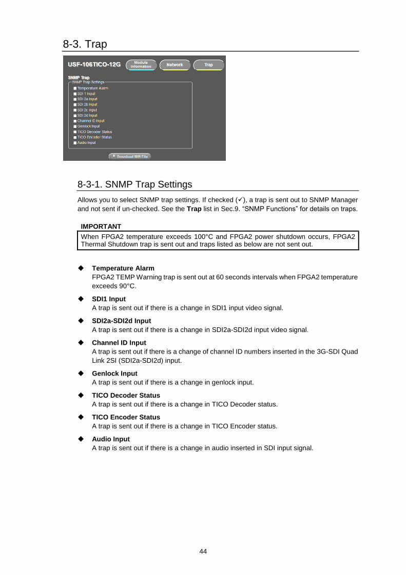
8-3. Trap
8-3-1. SNMP Trap Settings
Allows you to select SNMP trap settings. If checked (), a trap is sent out to SNMP Manager
and not sent if un-checked. See the Trap list in Sec.9. “SNMP Functions” for details on traps.
IMPORTANT
When FPGA2 temperature exceeds 100°C and FPGA2 power shutdown occurs, FPGA2 Thermal Shutdown trap is sent out and traps listed as below are not sent out.
Temperature Alarm
FPGA2 TEMP Warning trap is sent out at 60 seconds intervals when FPGA2 temperature
exceeds 90°C.
SDI1 Input
A trap is sent out if there is a change in SDI1 input video signal.
SDI2a-SDI2d Input
A trap is sent out if there is a change in SDI2a-SDI2d input video signal.
Channel ID Input
A trap is sent out if there is a change of channel ID numbers inserted in the 3G-SDI Quad
Link 2SI (SDI2a-SDI2d) input.
Genlock Input
A trap is sent out if there is a change in genlock input.
TICO Decoder Status
A trap is sent out if there is a change in TICO Decoder status.
TICO Encoder Status
A trap is sent out if there is a change in TICO Encoder status.
Audio Input
A trap is sent out if there is a change in audio inserted in SDI input signal.

45
8-3-2. Downloading MIB Files
Clicking this button at the bottom of the screen allows you to download the dedicated MIB
(Management Information Base) file used in SNMP managers. See Sec. 9. “SNMP Functions”
for details on MIB files.
8-4. Event Data
Pressing Event Data button opens the screen as shown below and allows you to save (Event
Export and load (Event Import) menu settings using the Event function.
Event Load
Loads event data (menu setting list) saved in USF-106TICO-12G and change settings.
1. Select the event number.
2. Click the Load button to load USF-106TICO-12G event data.
Event Export
Downloads event data (menu setting list) saved in USF-106TICO-12G to the PC as a .csv file.
1. Select the event number.
2. Click the Export button to download the USF-106TICO-12G event data.
Event Import
Uploads the csv files on the PC (conform data format to downloaded csv files) to the selected event
number of USF-106TICO-12G.
1. Select an event number.
2. Click the Browse button and select a .csv file in the PC.
3. Click the Import button to update USF-106TICO-12G event data.

46
8-5. Gamma Data / Gamut Data
* To be supported in the future.
Pressing Gamma Data (or Gamut Data) button opens the screen as shown below.
Gamma Data Export / Gamut Data Export
Downloads Gamma (or Gamut) data saved in USF-106TICO-12G to the PC as an original .lut file.
1. Select the User Gamma (or Gamut) number.
2. Click the Export button to download the USF-106TICO-12G Gamma (or Gamut) Data.
Gamma Data Import / Gamut Data Import
Uploads an .lut file on the PC (conform data format to downloaded .lut files) to the selected Gamma
(or Gamut) number of USF-105FS-12G.
1. Select the User Gamma (or Gamut) number.
2. Click the Browse button and select an .lut (or .gmt) file in the PC.
3. Click the Import button to update USF-106TICO-12G User Gamma (or Gamut) data.

47
9. SNMP Functions
The USF-106TICO-12G operations can be monitored by an external SNMP monitoring system
supporting SNMPv2C. The MIB (Management Information Base) files used by SNMP monitoring system
can be downloaded via the Web GUI. See Sec. 8-3-2. “Downloading MIB File” for MIB downloading
procedures. See the USF frame Operation Manual for SNMP settings.
GET List Object Group
Item Name Object name in MIB file Value OID Type Trap
OID : 1.3.6.1.4.1.20175.1.346.1.
Module Info
Product Name usf106Tico12GProductName USF-106TICO-12G 1 OCTET STRING
Product Code usf106Tico12GProductCode 1023866 2 INTEGER
Serial Number usf106Tico12GSerialNumber 18190001-18199999 3 INTEGER
Slot Number usf106Tico12GSlotNumber Slot1-12 4 INTEGER
FW1 Version usf106Tico12GFirmware1 Version
FW1 version 11 OCTET STRING
FW2 Version usf106Tico12GFirmware2 Version
FW2 version 12 OCTET STRING
FPGA1 Version usf106Tico12GFpga1Version FPGA1 version 13 OCTET STRING
FPGA2 Version *1 usf106Tico12GFpga2Version FPGA2 version 14 OCTET STRING
FPGA2 TEMP usf106Tico12GFpga2 Temperature
0-127℃ 101 INTEGER
Video
Video Source usf106Tico12GInputVideo Source
0: SDI1 1: SDI2a 2: SDI2b 3: SDI2c 4: SDI2d
201 INTEGER
Genlock Source usf106Tico12GInputGenlock Source
0: Genlock1 1: Genlock2
202 INTEGER
DRC Mode *2 usf106Tico12GDrcMode 0: Bypass 1: Operate
211 INTEGER
EOTF *2 usf106Tico12GEotf 1-10: User1-10 221 INTEGER
Input Color Space *2
usf106Tico12GInputColor Space
0: BT709 1: BT2020 2-6: User1-User5
222 INTEGER
OETF *2 usf106Tico12GOetf 1-10: User1-10 231 INTEGER
Output Color Space *2
usf106Tico12GOutputColor Space
0: BT709 1: BT2020 2-6: User1-User5
232 INTEGER
SDI1a Video Output *2
usf106Tico12GSdi1aVideo Output
0: Bypass 1: Operate
251 INTEGER
SDI1 Input Video Status *1 usf106Tico12GInputVideo StatusSdi1
Video signal status 401 OCTET STRING
SDI2a Input Video Status *1 usf106Tico12GInputVideo StatusSdi2a
Same as above 411 OCTET STRING
SDI2b Input Video Status *1 usf106Tico12GInputVideo StatusSdi2b
Same as above 412 OCTET STRING
SDI2c Input Video Status *1 usf106Tico12GInputVideo StatusSdi2c
Same as above 413 OCTET STRING
SDI2d Input Video Status *1 usf106Tico12GInputVideo StatusSdi2d
Same as above 414 OCTET STRING
SDI1a Output Video Status *1 usf106Tico12GOutputVideo StatusSdi1a
Same as above 501 OCTET STRING
SDI1b Output Video Status *1 usf106Tico12GOutputVideo StatusSdi1b
Same as above 502 OCTET STRING
SDI2a Output Video Status *1 usf106Tico12GOutputVideo StatusSdi2a
Same as above 511 OCTET STRING
SDI2b Output Video Status *1 usf106Tico12GOutputVideo StatusSdi2b
Same as above 512 OCTET STRING
SDI2c Output Video Status *1 usf106Tico12GOutputVideo StatusSdi2c
Same as above 513 OCTET STRING
SDI2d Output Video Status *1 usf106Tico12GOutputVideo StatusSdi2d
Same as above 514 OCTET STRING
Genlock Input Status *1 usf106Tico12GGenlockInput Status
Same as above 601 OCTET STRING

48
Object Group
Item Name Object name in MIB file Value OID Type Trap
Video
OID : 1.3.6.1.4.1.20175.1.346.1.602.1 (SDI 2 Input Channel ID Status)
SDI2 Terminal *1 usf106Tico12GSdi2Input ChannelIDTerminal
1: SDI2a 2: SDI2b 3: SDI2c 4: SDI2d
1.a *3 INTEGER
SDI2 Input CH ID *1 usf106Tico12GSdi2Input ChannelIDStatus
0: Not Used 1: Matched 2: Not Matched 3: Output Mode
2.a *3 INTEGER
SDI2 Input CH No. *1 usf106Tico12GSdi2Input ChannelIDNumber
0: None 1-4: CH1-CH4
3.a *3 INTEGER
OID : 1.3.6.1.4.1.20175.1.346.1.
TICO decoder status *1 usf106Tico12GTicoDecodeStatus
0: notTICO 1: prof1 2: prof2 99: disabled
701 INTEGER
TICO encoder status *1 usf106Tico12GTicoEncodeStatus
0: running 1: error 99: disabled
702 INTEGER
TICO compress mode status *1
usf106Tico12GTicoCompressModeStatus
0: compress4to1 1: compress8to1
703 INTEGER ○
OID : 1.3.6.1.4.1.20175.1.346.1.801.1 (Embedded Audio Status)
Audio
Embedded Audio CH No. *1 usf106Tico12GEmbedded AudioStatusChannel
1-16: CH1-CH16 1.b *4 INTEGER
Embedded Audio Input Status *1
usf106Tico12GEmbedded AudioInputChannelStatus
0: Loss 1: PCM 2: Async PCM 3: Silence 4: Async Silence 5: Dolby-E 6: Async Dolby-E 7: non PCM 8: AsyncNon PCM 9: Bypass
11.b *4 INTEGER
*1 When FPGA2 temperature error occurs and FPGA2 power supply is stopped, FPGA2 status cannot be get.
*2 Not supported in Ver.1.
*3 The “a” represents the BNC number. (1-4: SDI2a-SDI2d)
*4 The “b” represents the audio channel number.
49
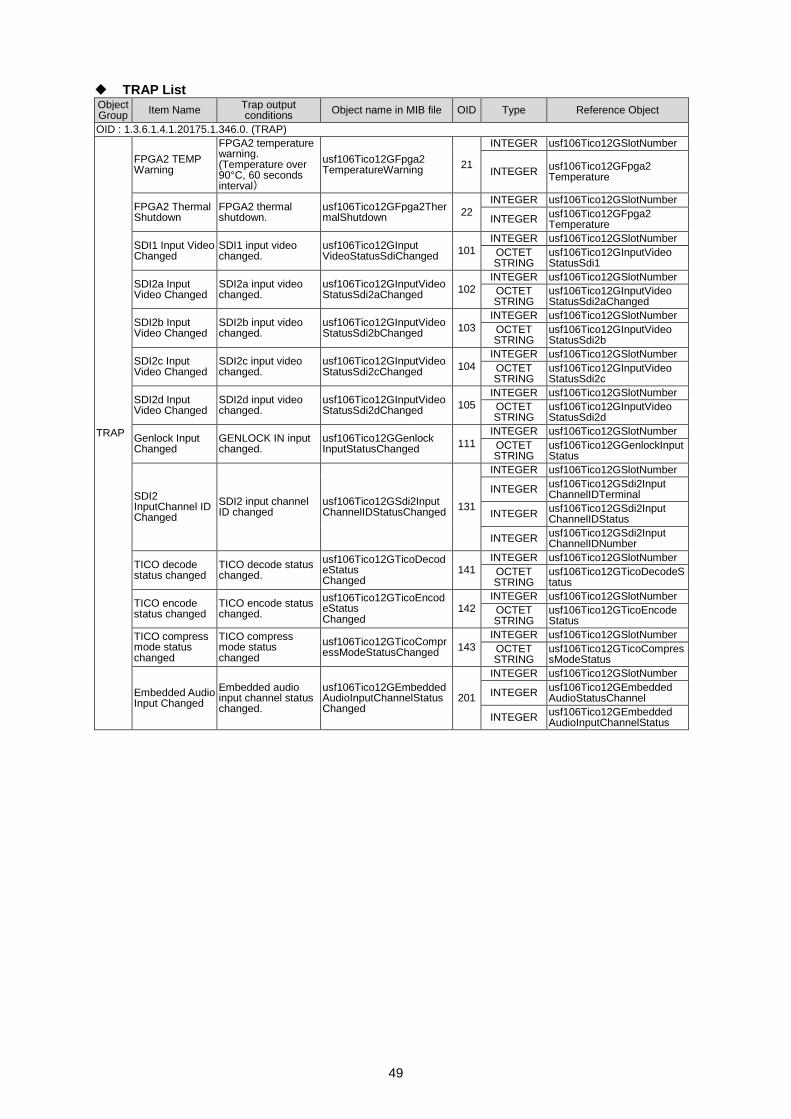
TRAP List Object Group
Item Name Trap output conditions
Object name in MIB file OID Type Reference Object
OID : 1.3.6.1.4.1.20175.1.346.0. (TRAP)
TRAP
FPGA2 TEMP Warning
FPGA2 temperature warning. (Temperature over 90°C, 60 seconds interval)
usf106Tico12GFpga2 TemperatureWarning
21
INTEGER usf106Tico12GSlotNumber
INTEGER usf106Tico12GFpga2 Temperature
FPGA2 Thermal Shutdown
FPGA2 thermal shutdown.
usf106Tico12GFpga2ThermalShutdown
22 INTEGER usf106Tico12GSlotNumber
INTEGER usf106Tico12GFpga2 Temperature
SDI1 Input Video Changed
SDI1 input video changed.
usf106Tico12GInput VideoStatusSdiChanged
101 INTEGER usf106Tico12GSlotNumber
OCTET STRING
usf106Tico12GInputVideo StatusSdi1
SDI2a Input Video Changed
SDI2a input video changed.
usf106Tico12GInputVideoStatusSdi2aChanged
102 INTEGER usf106Tico12GSlotNumber
OCTET STRING
usf106Tico12GInputVideo StatusSdi2aChanged
SDI2b Input Video Changed
SDI2b input video changed.
usf106Tico12GInputVideoStatusSdi2bChanged
103 INTEGER usf106Tico12GSlotNumber
OCTET STRING
usf106Tico12GInputVideo StatusSdi2b
SDI2c Input Video Changed
SDI2c input video changed.
usf106Tico12GInputVideoStatusSdi2cChanged
104 INTEGER usf106Tico12GSlotNumber
OCTET STRING
usf106Tico12GInputVideo StatusSdi2c
SDI2d Input Video Changed
SDI2d input video changed.
usf106Tico12GInputVideoStatusSdi2dChanged
105 INTEGER usf106Tico12GSlotNumber
OCTET STRING
usf106Tico12GInputVideo StatusSdi2d
Genlock Input Changed
GENLOCK IN input changed.
usf106Tico12GGenlock InputStatusChanged
111 INTEGER usf106Tico12GSlotNumber
OCTET STRING
usf106Tico12GGenlockInputStatus
SDI2 InputChannel ID Changed
SDI2 input channel ID changed
usf106Tico12GSdi2Input ChannelIDStatusChanged
131
INTEGER usf106Tico12GSlotNumber
INTEGER usf106Tico12GSdi2Input ChannelIDTerminal
INTEGER usf106Tico12GSdi2Input ChannelIDStatus
INTEGER usf106Tico12GSdi2Input ChannelIDNumber
TICO decode status changed
TICO decode status changed.
usf106Tico12GTicoDecodeStatus Changed
141 INTEGER usf106Tico12GSlotNumber
OCTET STRING
usf106Tico12GTicoDecodeStatus
TICO encode status changed
TICO encode status changed.
usf106Tico12GTicoEncodeStatus Changed
142 INTEGER usf106Tico12GSlotNumber
OCTET STRING
usf106Tico12GTicoEncode Status
TICO compress mode status changed
TICO compress mode status changed
usf106Tico12GTicoCompressModeStatusChanged
143 INTEGER usf106Tico12GSlotNumber
OCTET STRING
usf106Tico12GTicoCompressModeStatus
Embedded Audio Input Changed
Embedded audio input channel status changed.
usf106Tico12GEmbeddedAudioInputChannelStatusChanged
201
INTEGER usf106Tico12GSlotNumber
INTEGER usf106Tico12GEmbedded AudioStatusChannel
INTEGER usf106Tico12GEmbedded AudioInputChannelStatus
50
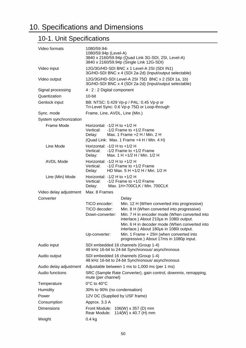
10. Specifications and Dimensions
10-1. Unit Specifications
Video formats 1080/59.94i 1080/59.94p (Level-A) 3840 x 2160/59.94p (Quad Link 3G-SDI, 2SI, Level-A) 3840 x 2160/59.94p (Single Link 12G-SDI)
Video input 12G/3G/HD-SDI BNC x 1 Level-A 2SI (SDI IN1) 3G/HD-SDI BNC x 4 (SDI 2a-2d) (Input/output selectable)
Video output 12G/3G/HD-SDI Level-A 2SI 75Ω BNC x 2 (SDI 1a, 1b) 3G/HD-SDI BNC x 4 (SDI 2a-2d) (Input/output selectable)
Signal processing 4 : 2 : 2 Digital component
Quantization 10-bit
Genlock input BB: NTSC: 0.429 Vp-p / PAL: 0.45 Vp-p or Tri-Level Sync: 0.6 Vp-p 75Ω or Loop-through
Sync. mode Frame, Line, AVDL, Line (Min.)
System synchronization
Frame Mode Horizontal: -1/2 H to +1/2 H Vertical: -1/2 Frame to +1/2 Frame Delay: Max. 1 Frame +2 H / Min. 2 H
(Quad Link: Max. 1 Frame +4 H / Min. 4 H)
Line Mode Horizontal: -1/2 H to +1/2 H Vertical: -1/2 Frame to +1/2 Frame Delay: Max. 1 H +1/2 H / Min. 1/2 H
AVDL Mode Horizontal: -1/2 H to +1/2 H Vertical: -1/2 Frame to +1/2 Frame Delay: HD Max. 5 H +1/2 H / Min. 1/2 H
Line (Min) Mode Horizontal: -1/2 H to +1/2 H Vertical: -1/2 Frame to +1/2 Frame Delay: Max. 1H+700CLK / Min. 700CLK
Video delay adjustment Max. 8 Frames
Converter Delay
TICO encoder: Min. 12 H (When converted into progressive)
TICO decoder: Min. 8 H (When converted into progressive)
Down-converter: Min. 7 H in encoder mode (When converted into interlace.) About 210μs in 1080i output.
Min. 6 H in decoder mode (When converted into interlace.) About 180μs in 1080i output.
Up-converter: Min. 1 Frame + 25H (when converted into progressive.) About 17ms in 1080p input.
Audio input SDI embedded 16 channels (Group 1-4) 48 kHz 16-bit to 24-bit Synchronous/ asynchronous
Audio output SDI embedded 16 channels (Group 1-4) 48 kHz 16-bit to 24-bit Synchronous/ asynchronous
Audio delay adjustment Adjustable between 1 ms to 1,000 ms (per 1 ms)
Audio functions SRC (Sample Rate Converter), gain control, downmix, remapping, mute (per channel)
Temperature 0°C to 40°C
Humidity 30% to 90% (no condensation)
Power 12V DC (Supplied by USF frame)
Consumption Approx. 3.3 A
Dimensions Front Module: 106(W) x 357 (D) mm Rear Module: 114(W) x 40.7 (H) mm
Weight 0.4 kg

51
10-2. External Dimensions
(All dimensions in mm)
3.2
Ser.No
USF-106TICO-12G12G/3G/HD-SDI IN1
3G/HD-SDI IO2b 2a2d 2c
12G/3G/HD-SDI OUT1a
1b
USF-106TICO-12G
106
35
7
33
4
114
40
.724
.513.5