operation maintenance specifications - hyundai...
TRANSCRIPT

All information in this Owner's Manual is current at the time of publication.However, Hyundai reserves the right to make changes at any time so thatour policy of continual product improvement may be carried out.
This manual applies to all Hyundai models and includes descriptions andexplanations of optional as well as standard equipment. As a result, youmay find material in this manual that does not apply to your specific vehi-cle.
OperationMaintenanceSpecifications

F2
Your Hyundai should not be modified in any way. Such modifications may adversely affect the per-formance, safety or durability of your Hyundai and may, in addition, violate conditions of the limitedwarranties covering the vehicle. Certain modifications may also be in violation of regulations estab-lished by the Department of Transportation and other government agencies in your country.
Your vehicle is equipped with electronic fuel injection and other electronic components. It is possiblefor an improperly installed/adjusted two-way radio or cellular telephone to adversely affect electronicsystems. For this reason, we recommend that you carefully follow the radio manufacturer's instruc-tions or consult your Hyundai dealer for precautionary measures or special instructions if you chooseto install one of these devices.
CAUTION: MODIFICATIONS TO YOUR HYUNDAI
TWO-WAY RADIO OR CELLULAR TELEPHONE INSTALLATION

F3
This manual includes information titled as WARNING, CAUTION and NOTICE.
These titles indicate the following:
✽ NOTICEThis indicates that interesting or helpful information is being provided.
SAFETY AND VEHICLE DAMAGE WARNING
WARNING This indicates that a condition may result in harm, serious injury or death to you or otherpersons if the warning is not heeded. Follow the advice provided with the warning.
CAUTIONThis indicates that a condition may result in damage to your vehicle or its equipment if thecaution is not heeded. Follow the advice provided with the caution.

F4
FOREWORD
Thank you for choosing Hyundai. We are pleased to welcome you to the growing number of discriminating people who driveHyundais. The advanced engineering and high-quality construction of each Hyundai we build is something of which we're veryproud.
Your Owner's Manual will introduce you to the features and operation of your new Hyundai. It is suggested that you read it care-fully because the information it contains can contribute greatly to the satisfaction you receive from your new car.
The manufacturer also recommends that all service and maintenance on your car be performed by an authorized Hyundai deal-er.
HYUNDAI MOTOR INDIA
Note : Because future owners will also need the information included in this manual, if you sell this Hyundai, please leave the man-ual in the vehicle for their use. Thank you.
Copyright 2012 Hyundai Motor India. All rights reserved. No part of this publication may be reproduced, stored in any retrievalsystem or transmitted in any form or by any means without the prior written permission of Hyundai Motor India.
CAUTIONSevere engine and transmission damage may result from the use of poor quality fuels and lubricants that do not meetHyundai specifications. You must always use high quality fuels and lubricants that meet the specifications listed on Page10-4 in the Vehicle Specifications section of the Owner's Manual.

3
4
5
6
7
8
9
10
I
Introduction
Your vehicle at a glance
Safety system of your vehicle
Features of your vehicle
Driving your vehicle
What to do in an emergency
Maintenance
Specifications & Consumer information
Index
1Maintenance record sheet
2Hyundai warranty policy


Maintenance Record Sheet ...................................1-2
1Maintenance Record Sheet

Maintenance Record Sheet

Maintenance Record Sheet

Maintenance Record Sheet

Hyundai New Vehicle Warranty / 2-2Parts Replacement Warranty / 2-3Emission Warranty / 2-5
Pre delivery inspection & Warranty RegistrationCard1st Free Service Coupon2nd Free Service Coupon3rd Free Service Coupon
2Hyundai Warranty Policy

Hyundai Warranty Policy
22
Hyundai Motor India Limited hereinaftercalled "HMIL", warrants that each newHyundai vehicle sold shall be free fromany defects in material and workmanship,under normal use and maintenance, sub-ject to the following terms and conditions.
1. Warranty period
This warranty shall exist for a period of 24months from the date of delivery to thefirst purchaser irrespective of the mileage.However, the warranty forbeing used for commercial purpose suchas Taxi/Tourist operation is 24 months/40,000 kilometers from the date of deliverywhich ever is earlier. This warranty istransferable to subsequent owner for theremaining warranty period.
2. What is covered
Except as provided in paragraph 3 here-of, our Authorized Dealers shall eitherrepair or replace, any Hyundai genuinepart that is acknowledged by HMIL to bedefective in material or workmanshipwithin the warranty period stipulated
above, at no cost to the owner of theHyundai vehicle for parts or labour. Suchdefective parts which have beenreplaced will become the property ofHMIL.
3. What is not covered
This warranty shall not apply to:o Normal maintenance services other
than cleaning and polishing, minoradjustments, engine tuning, oil/fluidchanges, filters replenishment, fas-tener retightening, wheel balancing,wheel alignment and tyre rotation etc.
o Replacement of parts as a result ofnormal wear and tear such as sparkplugs, belts, brake pads and linings,clutch disc/facing, filters, wiperblades, bulbs, fuses, etc.
o Damage or failure resulting from:Negligence of proper maintenanceas required in this Owner'sManual and Service Booklet.
Misuse, abuse, accident, theft,flooding or fire.Use of improper or insufficient
fuel, fluids or lubricants.Use of parts other than HyundaiGenuine Parts.Any device and/or accessoriesnot supplied by HMIL.Modifications, alterations, tam-pering or improper repair.Parts used in applications ofwhich they were not designed ornot approved by HMIL.Slight irregularities not recog-nised as affecting quality or func-tion of the vehicle or parts, suchas slight noise or vibrations, oritems considered characteristic ofthe vehicle. Airborne "fallout", Industrial fallout, acid rain, hail and windstorms, or other Acts of God.Paint scratches, dents or similarpaint or body damage. Action of road elements (sand,gravel, dust or road debris) whichresults in stone chipping of paintor glass.
HYUNDAI NEW VEHICLE WARRANTY

2 3
Hyundai Warranty Policy
o Incidental or consequential damages,including without limitation, loss oftime, inconvenience, loss of use ofvehicle or commercial loss.
This warranty is the entire warranty givenby HMIL for Hyundai vehicles and nodealer or its or his agent or employee isauthorized to extend or enlarge this war-ranty and no dealer or its or his agent oremployee is authorized to make any oralwarranty on HMIL's behalf.
HMIL reserves the right to make anychange in design or make any improve-ment on the vehicle at any time withoutany obligation to make the same changeon vehicles previously sold. HMIL reserves the right for the final deci-sion in all warranty matters.
Owner's Responsibilities
o Proper use, maintenance and care ofvehicle in accordance with theinstructions contained in this Owner'sManual and Service Booklet. If thevehicle is subject to severe usageconditions, such as operation inextremely dusty, rough, more repeat-ed short distance driving or heavy citytraffic during hot weather, mainte-nance of vehicle should be donemore frequently as mentioned in thisOwner's Manual and Service Booklet.
o Retention of maintenance servicerecords. It may be necessary for thecustomer to show that the requiredmaintenance has been performed, asspecified in this Owner's Manual andService Booklet.
o Delivery of the vehicle during regularservice business hours to any author-ized Hyundai Dealer to obtain war-ranty service.
o In order to maintain the validity of thisBasic Warranty, the vehicle must beserviced by Hyundai Authorizedworkshop in accordance to theOwner’s Manual and Service Booklet
Hyundai Motor India Limited hereinaftercalled "HMIL", warrants that each newHyundai Genuine replacement part pur-chased from and installed by HyundaiAuthorized Dealer shall be free from anydefects in material or workmanship,under normal use and maintenance, sub-ject to the following terms and conditions.
1. Warranty period
This warranty shall exist for a period of 6months or until the vehicle has been driv-en for a distance of 10,000 Kilometersfrom the date of installation of replace-ment part by Hyundai Authorized Dealer,whichever occurs first.
2. What is covered
Except as provided in paragraph 3 here-of, our Authorized Dealer who had soldand installed the replacement part earliershall either repair or replace the saidHyundai genuine part that is acknowl-edged by HMIL to be defective in materi-al or workmanship within the warranty
Batteries, Tyres and Tubes originallyequipped on Hyundai vehicles arewarranted directly by the respectivemanufacturers and not by HMIL.
PARTS REPLACEMENT WARRANTY
Hyundai Warranty Policy
42
period stipulated above, at no cost to theowner of the Hyundai vehicle for parts orlabour.
3. What is not covered
This warranty shall not apply to:
o Normal maintenance services ofparts such as cleaning, adjustment orreplacement (i.e. spark plugs that areoil fouled, lead fouled, or which faildue to the use of low grade fuel).
o Parts that fail due to abuse, misuse,neglect, alteration or accident orwhich have been improperly lubricat-ed or repaired.
o Parts used in applications for whichthey were not designed or approvedby HMIL.
o Failure due to normal wear of parts.o Direct or indirect failures caused by
misuse and improper maintenance ofvehicle and installation of non-Hyundai parts on the vehicle.
o Any vehicle on which the odometerreading has been altered so thatmileage cannot be accurately deter-
mined. o Incidental or consequential damages,
including without limitation, loss oftime, inconvenience, loss of use ofvehicle or commercial loss.
This warranty is the entire warranty givenby HMIL for Hyundai replacement partsand no dealer or its or his agent oremployee is authorized to extend orenlarge this warranty and no dealer or itsor his agent or employee is authorized tomake any oral warranty on HMIL'sbehalf.HMIL reserves the right for the final deci-sion in all warranty matters.
Owner's Responsibilities
o Proper use, maintenance and care ofthe vehicle in accordance with theinstructions contained in the Owner'sManual and Service Booklet.
o Retention of maintenance servicerecords. It may be necessary for thecustomer to show that the requiredmaintenance has been performed, asspecified in this Owner's Manual andService Booklet.
o Retention of the customer's copy ofthe original repair order and itsinvoice/bill against which the part wasreplaced.
o Delivery of the vehicle during regularservice business hours to the sameHyundai Authorized Dealer who hadsold and installed the replacementpart.
o In order to maintain the validity of thisParts replacement Warranty, thevehicle must be serviced by HyundaiAuthorized workshop in accordanceto the Owner’s Manual and ServiceBooklet.
2 5
Hyundai Warranty Policy
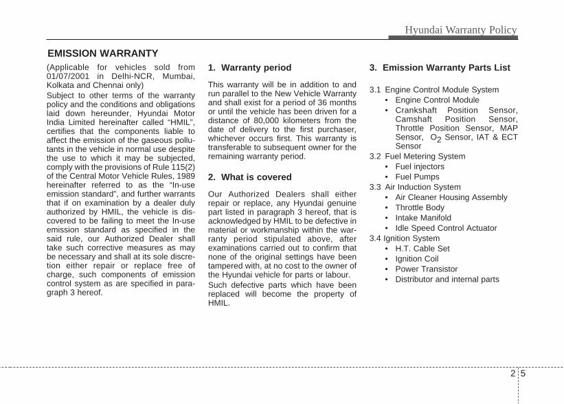
EMISSION WARRANTY(Applicable for vehicles sold from01/07/2001 in Delhi-NCR, Mumbai,Kolkata and Chennai only)Subject to other terms of the warrantypolicy and the conditions and obligationslaid down hereunder, Hyundai MotorIndia Limited hereinafter called “HMIL”,certifies that the components liable toaffect the emission of the gaseous pollu-tants in the vehicle in normal use despitethe use to which it may be subjected,comply with the provisions of Rule 115(2)of the Central Motor Vehicle Rules, 1989hereinafter referred to as the “In-useemission standard”, and further warrantsthat if on examination by a dealer dulyauthorized by HMIL, the vehicle is dis-covered to be failing to meet the In-useemission standard as specified in thesaid rule, our Authorized Dealer shalltake such corrective measures as maybe necessary and shall at its sole discre-tion either repair or replace free ofcharge, such components of emissioncontrol system as are specified in para-graph 3 hereof.
1. Warranty period
This warranty will be in addition to andrun parallel to the New Vehicle Warrantyand shall exist for a period of 36 monthsor until the vehicle has been driven for adistance of 80,000 kilometers from thedate of delivery to the first purchaser,whichever occurs first. This warranty istransferable to subsequent owner for theremaining warranty period.
2. What is covered
Our Authorized Dealers shall eitherrepair or replace, any Hyundai genuinepart listed in paragraph 3 hereof, that isacknowledged by HMIL to be defective inmaterial or workmanship within the war-ranty period stipulated above, afterexaminations carried out to confirm thatnone of the original settings have beentampered with, at no cost to the owner ofthe Hyundai vehicle for parts or labour. Such defective parts which have beenreplaced will become the property ofHMIL.
3. Emission Warranty Parts List
3.1 Engine Control Module System• Engine Control Module• Crankshaft Position Sensor,
Camshaft Position Sensor,Throttle Position Sensor, MAPSensor, O2 Sensor, IAT & ECTSensor
3.2 Fuel Metering System• Fuel injectors • Fuel Pumps
3.3 Air Induction System• Air Cleaner Housing Assembly • Throttle Body• Intake Manifold • Idle Speed Control Actuator
3.4 Ignition System• H.T. Cable Set• Ignition Coil• Power Transistor • Distributor and internal parts

Hyundai Warranty Policy
62
3.5 Evaporative Emission Control System• Vapour Storage Canister • Fuel Tank• Fuel Filler Tube and Fuel filler
Cap• Purge Control Solenoid Valve• Canister Close Valve
3.6 PCV System• PCV Valve.• PCV Hoses• Oil Filler Cap
3.7 Catalytic Converter System• Exhaust Manifold• Exhaust Pipe Assembly• Catalytic Converter
3.8 Exhaust Gas Recirculation(EGR) System (Diesel Engines)• EGR Control System
3.9 Miscellaneous items used in above Systems• Vacuum hoses, clamps, fittings,
tubing or mounting hardwareused with the above systems.Valves, Switches and Solenoids.
4. What is not covered
This Emission Warranty shall not applyto:o Normal maintenance services includ-
ing without limitation, engine tuning,oil/fluid changes, filters replenish-ment, etc.
o Replacement of parts as a result ofnormal wear and tear such as sparkplugs, filters, etc.
o The vehicle reported without valid‘Pollution Under Control’ certificatefor the period immediately precedingthe test during which the failure is dis-covered.
o The vehicle which has been run onadulterated fuel or lubricant orfuel/lubricants other than those spec-ified by HMIL.
o Damage or failure resulting from:Negligence of proper mainte-nance as required in this Owner’sManual and Service Booklet.Misuse, abuse, accident, theft,flooding or fire.Use of improper or insufficientfuel, fluids or lubricants.
Any repair carried out other thanby Hyundai Authorized Dealer/Service Centre.Use of parts other than HyundaiGenuine Parts.Any device and/or accessoriesnot supplied by HMIL.Modifications, alterations, tam-pering or improper repair.Parts used in applications forwhich they were not designed ornot approved by HMIL.Any penalties that may becharged by statutory authoritieson account of failure to complywith the In-use emission stan-dards. The vehicle in which the odome-ter has been tampered with,changed or been disconnected.
o Any consequential repairs or replace-ment of parts which may be foundnecessary to establish compliance toIn-use emission standards, in addi-tion to the replacement of the compo-nents covered under EmissionWarranty, will not be made free of

2 7
Hyundai Warranty Policy
cost unless such parts are also foundto be in warrantable condition withinthe scope and limit of the NewVehicle Warranty.
o Incidental or consequential damages,including without limitation, loss oftime, inconvenience, loss of use ofvehicle or commercial loss.
This warranty is the entire warranty givenby HMIL for Hyundai vehicles and nodealer or its or his agent or employee isauthorized to extend or enlarge this war-ranty and no dealer or its or his agent oremployee is authorized to make any oralwarranty on HMIL’s behalf.
HMIL reserves the right to make anychange in design or make any improve-ment on the vehicle at any time withoutany obligation to make the same changeon vehicles previously sold.HMIL reserves the right for the final deci-sion in all warranty matters.
OWNER'S RESPONSIBILITIES
o Proper use, maintenance and care ofvehicle in accordance with theinstructions contained in this Owner’sManual and Service Booklet. If thevehicle is subject to severe usageconditions, such as operation inextremely dusty, rough, more repeat-ed short distance driving or heavy citytraffic during hot weather, mainte-nance of vehicle should be donemore frequently as mentioned in thisOwner’s Manual and ServiceBooklet.
o In order to maintain the validity of thisEmission Warranty, the vehicle mustbe serviced by Hyundai AuthorizedDealer or Service Centre in accor-dance to the Owner’s Manual andService Booklet.
o Retention of maintenance servicerecords. It may be necessary for thecustomer to show that the requiredmaintenance has been performed, asspecified in this Owner’s Manual andService Booklet.
o Immediate Delivery of the vehicle to
any authorized Hyundai Dealer upondiscovery of failure to comply with theIn-use emission standard inspite ofproper use, maintenance and care ofvehicle in accordance with theinstructions contained in this Owner’sManual and Service Booklet.
o Production of “Pollution UnderControl" (PUC) certificate valid for theperiod immediately preceding the testduring which the failure is discovered,the test having been carried outeither for obtaining a new certificate,or pursuant upon being directed byan officer as referred to in sub-rule(2) of Rule 116 of the Central MotorVehicles Rules.
HYUNDAI EXTENDEDWARRANTY*HMIL offers optional paid extendedwarranty on selected models, in addi-tion to the basic new vehicle warran-ty. For more details on HyundaiExtended Warranty please call thenearest dealer or our toll free number1-800-11-4645*Conditions apply
dealer

How to use this manual / 3-2Fuel requirements / 3-3Vehicle break-in process / 3-6Indicator symbols on the instrument cluster / 3-7
3Introduction

Introduction
23
We want to help you get the greatestpossible driving pleasure from your vehi-cle. Your Owner’s Manual can assist youin many ways. We strongly recommendthat you read the entire manual. In orderto minimize the chance of death or injury,you must read the WARNING and CAU-TION sections in the manual.Illustrations complement the words inthis manual to best explain how to enjoyyour vehicle. By reading your manual,you learn about features, important safe-ty information, and driving tips under var-ious road conditions.The general layout of the manual is pro-vided in the Table of Contents. A goodplace to start is the index; it has analphabetical listing of all information inyour manual.Sections: This manual has ten sectionsplus an index. Each section begins with abrief list of contents so you can tell at aglance if that section has the informationyou want.
You will find various WARNINGs,CAUTIONs, and NOTICEs in this manu-al. These WARNINGs were prepared toenhance your personal safety. Youshould carefully read and follow ALL pro-cedures and recommendations providedin these WARNINGs, CAUTIONs and
NOTICEs.
✽ NOTICEA NOTICE indicates interesting or help-ful information is being provided.
HOW TO USE THIS MANUAL
WARNING A WARNING indicates a situation inwhich harm, serious bodily injury ordeath could result if the warning isignored.
CAUTIONA CAUTION indicates a situation inwhich damage to your vehicle couldresult if the caution is ignored.
3 3
Introduction
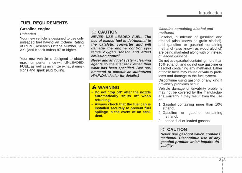
Gasoline engineUnleadedYour new vehicle is designed to use onlyunleaded fuel having an Octane Ratingof RON (Research Octane Number) 91/AKI (Anti-Knock Index) 87 or higher.
Your new vehicle is designed to obtainmaximum performance with UNLEADEDFUEL, as well as minimize exhaust emis-sions and spark plug fouling.
Gasoline containing alcohol andmethanolGasohol, a mixture of gasoline andethanol (also known as grain alcohol),and gasoline or gasohol containingmethanol (also known as wood alcohol)are being marketed along with or insteadof leaded gasoline.Do not use gasohol containing more than10% ethanol, and do not use gasoline orgasohol containing any methanol. Eitherof these fuels may cause drivability prob-lems and damage to the fuel system.Discontinue using gasohol of any kind ifdrivability problems occur.Vehicle damage or drivability problemsmay not be covered by the manufactur-er’s warranty if they result from the useof:1. Gasohol containing more than 10%
ethanol.2. Gasoline or gasohol containing
methanol.3. Leaded fuel or leaded gasohol.
FUEL REQUIREMENTS
WARNING • Do not "top off" after the nozzle
automatically shuts off whenrefueling.
• Always check that the fuel cap isinstalled securely to prevent fuelspillage in the event of an acci-dent.
CAUTIONNEVER USE LEADED FUEL. Theuse of leaded fuel is detrimental tothe catalytic converter and willdamage the engine control sys-tem’s oxygen sensor and affectemission control.Never add any fuel system cleaningagents to the fuel tank other thanwhat has been specified. (We rec-ommend to consult an authorizedHYUNDAI dealer for details.)
CAUTIONNever use gasohol which containsmethanol. Discontinue use of anygasohol product which impairs dri-vability.
Introduction
43
Use of MTBEHYUNDAI recommends avoiding fuelscontaining MTBE (Methyl Tertiary ButylEther) over 15.0% vol. (Oxygen Content2.7% weight) in your vehicle.Fuel containing MTBE over 15.0% vol.(Oxygen Content 2.7% weight) mayreduce vehicle performance and producevapor lock or hard starting.
Do not use methanolFuels containing methanol (wood alco-hol) should not be used in your vehicle.This type of fuel can reduce vehicle per-formance and damage components ofthe fuel system.
Fuel AdditivesHYUNDAI recommends that you usegood quality gasolines. For customerswho do not use good quality gasolinesincluding fuel additives regularly, andhave problems starting or the enginedoes not run smoothly, one bottle ofadditives added to the fuel tank at every5,000km. Additives are available fromyour authorized HYUNDAI dealer alongwith information on how to use them. Donot mix other additives. Operation in foreign countriesIf you are going to drive your vehicle inanother country, be sure to:• Observe all regulations regarding reg-
istration and insurance.• Determine that acceptable fuel is avail-
able.
Diesel engineDiesel fuelDiesel engine must be operated only oncommercially available diesel fuel thatcomplies with EN 590 or comparablestandard. (EN stands for "EuropeanNorm"). Do not use marine diesel fuel,heating oils, or non-approved fuel addi-tives, as this will increase wear andcause damage to the engine and fuelsystem. The use of non-approved fuelsand / or fuel additives will result in a limi-tation of your warranty rights. Diesel fuel of above cetane 51 is used inyour vehicle. If two types of diesel fuelare available, use summer or winter fuelproperly according to the following tem-perature conditions.• Above -5°C (23°F) ... Summer type
diesel fuel.• Below -5°C (23°F) ... Winter type
diesel fuel.
Watch the fuel level in the tank very care-fully : If the engine stops through fuel fail-ure, the circuits must be completelypurged to permit restarting.
CAUTIONYour New Vehicle Limited Warrantymay not cover damage to the fuelsystem and any performance prob-lems that are caused by the use offuels containing methanol or fuelscontaining MTBE (Methyl TertiaryButyl Ether) over 15.0% vol.(Oxygen Content 2.7% weight.)

3 5
Introduction
Biodiesel Commercially supplied Diesel blends ofno more than 7% biodiesel, commonlyknown as "B7 Diesel" may be used inyour vehicle if Biodiesel meets EN 14214or equivalent specifications. (EN standsfor "European Norm"). The use of biofu-els exceeding 7% made from rapeseedmethyl ester (RME), fatty acid methylester (FAME), vegetable oil methyl ester(VME) etc. or mixing diesel exceeding7% with biodiesel will cause increasedwear or damage to the engine and fuelsystem. Repair or replacement of wornor damaged components due to the useof non approved fuels will not be coveredby the manufactures warranty.
CAUTION• Do not let any gasoline or water
enter the tank. This would make itnecessary to drain it out and tobleed the lines to avoid jammingthe injection pump and damagingthe engine.
• In winter, in order to cut downincidents due to freezing, paraffinoil may be added to the fuel if thetemperature drops to below -10°C(14°F). Never use more than 20%paraffin oil.
CAUTION - Diesel FuelIt is recommended to use the regu-lated automotive diesel fuel fordiesel vehicle equipped with theDPF system.If you use diesel fuel including highsulfur (more than 50 ppm sulfur)and unspecified additives, it cancause the DPF system to be dam-aged and white smoke can be emit-ted.
CAUTION• Never use any fuel, whether
diesel, B7 biodiesel or otherwise,that fails to meet the latest petro-leum industry specification.
• Never use any fuel additives ortreatments that are not recom-mended or approved by the vehi-cle manufacturer.

Introduction
63
No special break-in period is needed. Byfollowing a few simple precautions for thefirst 1,000 km (600 miles) you may add tothe performance, economy and life ofyour vehicle.• Do not race the engine.• While driving, keep your engine speed
(rpm, or revolutions per minute)between 2,000 rpm and 4,000 rpm.
• Do not maintain a single speed for longperiods of time, either fast or slow.Varying engine speed is needed toproperly break-in the engine.
• Avoid hard stops, except in emergen-cies, to allow the brakes to seat prop-erly.
• Don't let the engine idle longer than 3minutes at one time.
• Don't tow a trailer during the first 2,000km (1,200 miles) of operation.
VEHICLE BREAK-IN PROCESS

3 7
Introduction
INDICATOR SYMBOLS ON THE INSTRUMENT CLUSTER
Seat belt warning light
High beam indicator
Turn signal indicator
ABS warning light*
Parking brake & Brake fluidwarning light
Engine oil pressure warninglight
Malfunction indicator light
Air bag warning light*
Immobilizer indicator*
Low fuel level warning light
*: if equipped❈: For more detailed explanations, refer
to section 6, “Instrument cluster”.
Charging system warning light
Tail light indicator
Trunk lid open warning light
Front fog light indicator* Glow indicator (Diesel only)
Fuel filter warning light (Diesel only)
Shift pattern indicator*
Electric power steering (EPS)system warning light
Door ajar warning light
ECO indicator*
Manual transaxle shift indicator*
Engine coolant temperaturewarning light


Interior overview / 4-2Instrument panel overview / 4-4Engine compartment / 4-6
4Your vehicle at a glance

Your vehicle at a glance
24
INTERIOR OVERVIEW
1. Door lock/unlock button ........................6-13
2. Outside rearview mirror control switch* ..................................................6-30
3. Central door lock switch* ......................6-13
4. Power window lock button* ..................6-20
5. Power window switches* ......................6-19
6. Instrument panel illumination control switch* ..................................................6-34
7. Headlight leveling device* ....................6-64
8. Fuel filler lid release lever ....................6-24
9. Trunk lid release lever ..........................6-16
10. Fuse box ............................................9-51
11. Hood release lever..............................6-22
12. Brake pedal ..........................................7-3
13. Accelerator pedal ................................7-3
14. Steering wheel manual tilt control* ................................................6-27
* : if equipped
ORBI011001
* The actual interior may differ from the illustration.
■ Automatic Transmission

4 3
Your vehicle at a glance
INTERIOR OVERVIEW
* The actual interior may differ from the illustration.
ORBI010001
1. Door lock/unlock button ......................6-13
2. Outside rearview mirror control switch* ..................................................6-30
3. Central door lock switch* ....................6-13
4. Power window lock button* ..................6-20
5. Power window switches* ....................6-19
6. Instrument panel illumination controlswitch* ..................................................6-34
7. Headlight leveling device* ....................6-64
8. Fuel filler lid release lever ....................6-24
9. Trunk lid release lever ..........................6-16
10. Fuse box ............................................9-51
11. Hood release lever..............................6-22
12. Clutch pedal ........................................6-52
13. Brake pedal ..........................................7-3
14. Accelerator pedal ..................................7-3
15. Steering wheel manual tilt control* ....6-27
■ Manual Transmission
15
12
13
14

Your vehicle at a glance
44
INSTRUMENT PANEL OVERVIEW
1. Driver’s front air bag* ......................5-29
2. Light control/Turn signals.................6-63
3. Instrument cluster ............................6-33
4. Wiper/Washer ..................................6-66
5. Ignition switch* ...................................7-5
6. Engine start/stop button* ...................7-8
7. Digital clock and audio* ...................6-94
8. Steering wheel .................................6-27
9. Steering wheel audio control* ..........6-98
10. Climate control system*.........6-71/6-80
11. Hazard warning flasher switch.......6-60
12. Shift lever...............................7-14/7-17
13. Parking brake lever........................7-24
14. Passenger’s front air bag* .............5-29
15. Glove box.......................................6-91
16. Power outlet*..................................6-93
* : if equipped
ORBI011002
■ Automatic Transmission

4 5
Your vehicle at a glance
INSTRUMENT PANEL OVERVIEW
1. Driver’s front air bag* .......................5-29
2. Light control/Turn signals.................6-63
3. Instrument cluster ............................6-63
4. Wiper/Washer ..................................6-66
5. Ignition switch* ...................................7-5
6. Engine start/stop button* ...................7-8
7. Digital clock and audio* ......................6-94
8. Steering wheel .................................6-27
9. Steering wheel audio control* ..........6-98
10. Climate control system*.........6-71/7-17
11. Hazard warning flasher switch.......6-60
12. Shift lever...............................7-14/7-17
13. Parking brake lever........................7-24
14. Passenger’s front air bag* .............5-29
15. Glove box.......................................6-91
16. Power outlet*..................................6-93
* : if equipped
ORBI011002
■ Manual Transmission

Your vehicle at a glance
64
ENGINE COMPARTMENT
ORBI071001G/ORBI071001
1. Engine coolant reservoir...................9-23
2. Windshield washer fluid reservoir.....9-29
3. Radiator cap .....................................9-25
4. Engine oil filler cap ...........................9-21
5. Engine oil dipstick.............................9-21
6. Brake/clutch* fluid reservoir..............9-26
7. Air cleaner ........................................9-31
8. Fuse box...........................................9-51
9. Positive battery terminal ..................9-37
10. Negative battery terminal ..............9-37
11. Automatic transaxle fluid dipstick* .........................................9-27
* : if equipped
■ Gasoline Engine
■ Diesel Engine
* The actual engine room may differ from the illustration.
Seats / 5-2Seat belts / 5-9Child restraint system / 5-18Air bag - supplemental restraint system / 5-23
5Safety features of your vehicle

Safety features of your vehicle
25
Driver’s seat(1) Forward and backward(2) Seatback angle(3) Seat cushion height(4) Headrest(5) Armrest*
Front passenger’s seat(6) Forward and backward(7) Seatback angle(8) Headrest
Rear seat(9) Headrest*(10) Armrest*
*: if equipped
SEATS
ORBI031001

5 3
Safety features of your vehicle
WARNING - Driver’s seat• Never attempt to adjust the seat
while the vehicle is moving. Thiscould result in loss of control,and an accident causing death,serious injury, or property dam-age.
• Do not allow anything to interferewith the normal position of theseatback. Storing items against aseatback or in any other wayinterfering with proper locking ofa seatback could result in seri-ous or fatal injury in a suddenstop or collision.
• Always drive and ride with yourseatback upright and the lap por-tion of the seat belt snug and lowacross the hips. This is the bestposition to protect you in case ofan accident.
• In order to avoid unnecessaryand perhaps severe air baginjuries, always sit as far back aspossible from the steering wheelwhile maintaining comfortablecontrol of the vehicle. We recom-mend that your chest be at least250 mm (10 inches) away fromthe steering wheel.
WARNING - Loose objectsLoose objects in the driver’s footarea could interfere with the opera-tion of the foot pedals, possiblycausing an accident. Do not placeanything under the front seats.
WARNING - Driverresponsibility for passen-gers
Riding in a vehicle with the seat-back reclined could lead to seriousor fatal injury in an accident. If aseat is reclined during an accident,the occupant’s hips may slideunder the lap portion of the seatbelt applying great force to theunprotected abdomen. Serious orfatal internal injuries could result.The driver must advise the passen-ger to keep the seatback in anupright position whenever the vehi-cle is in motion.
WARNINGDo not use a sitting cushion thatreduces friction between the seatand passenger. The passenger'ships may slide under the lap por-tion of the seat belt during an acci-dent or a sudden stop. Serious orfatal internal injuries could resultbecause the seat belt can't operatenormally.
WARNING - Uprightingseat
When you return the seatback to itsupright position, hold the seatbackand return it slowly and be surethere are no other occupantsaround the seat. If the seatback isreturned without being held andcontrolled, the back of the seatcould spring forward resulting inaccidental injury to a person struckby the seatback.

Safety features of your vehicle
45
Front seatManual adjustmentForward and backwardTo move the seat forward or backward:1. Pull the seat slide adjustment lever
that is under the front edge of the seatcushion up and hold it.
2. Slide the seat to the position youdesire.
3. Release the lever and make sure theseat is locked in place.
Adjust the seat before driving, and makesure the seat is locked securely by tryingto move forward and backward withoutusing the lever. If the seat moves, it is notlocked properly.
Seatback angleTo recline the seatback:1. Lean forward slightly and lift up on the
seatback recline lever located on theoutside of the seat at the rear.
2. Carefully lean back on the seat andadjust the seatback of the seat to theposition you desire.
3. Release the lever and make sure theseatback is locked in place. (The leverMUST return to its original position forthe seatback to lock.)
ORBI031003ORBI031002
WARNINGAfter adjusting the seat, alwayscheck that it is securely locked intoplace by attempting to move theseat forward or reverse withoutusing the lock release lever.Sudden or unexpected movementof the driver's seat could cause youto lose control of the vehicle result-ing in an accident.
WARNING• Do not adjust the seat while wear-
ing seat belts. Moving the seatcushion forward may causestrong pressure on the abdomen.
• Use extreme caution so thathands or other objects are notcaught in the seat mechanismswhile the seat is moving.
• Do not put a cigarette lighter onthe floor or seat. When you oper-ate the seat, gas may gush out ofthe lighter and cause fire.

5 5
Safety features of your vehicle
Seat cushion height (for driver’s seat)To change the height of the seat cushion,rotate the knob located on the outside ofthe seat cushion.
Armrest (for driver’s seat) (if equipped)Your front seats have the armrest locat-ed on the side of seatback. To use the armrest, swing down the arm-rest to the lowest position.
HeadrestThe driver's and front passenger's seatsare equipped with a headrest for theoccupant's safety and comfort. The headrest not only provides comfortfor the driver and front passenger, butalso helps to protect the head and neckin the event of a collision.
ORBI031004 ORBI031006 OMG038400

Safety features of your vehicle
65
Adjusting the height up and downTo raise the headrest, pull it up to thedesired position (1). To lower the head-rest, push and hold the release button (2)on the headrest support and lower theheadrest to the desired position (3).
RemovalTo remove the headrest, raise it as far asit can go then press the release button (1)while pulling upward (2).To reinstall the headrest, put the head-rest poles (3) into the holes while press-ing the release button (1). Then adjust itto the appropriate height.
WARNING • For maximum effectiveness in
case of an accident, the headrestshould be adjusted so the middleof the headrest is at the sameheight of the center of gravity ofan occupant's head. Generally,the center of gravity of most peo-ple's head is similar with theheight of the top of their eyes.Also, adjust the headrest asclose to your head as possible.For this reason, the use of acushion that holds the body awayfrom the seatback is not recom-mended.
• Do not operate the vehicle withthe headrests removed as severeinjury to the occupants mayoccur in the event of an accident.Headrests may provide protec-tion against neck injuries whenproperly adjusted.
• Do not adjust the headrest posi-tion of the driver's seat while thevehicle is in motion.
ORBC030006 ORBC030007
WARNINGMake sure the headrest locks inposition after adjusting it to proper-ly protect the occupants.
5 7
Safety features of your vehicle
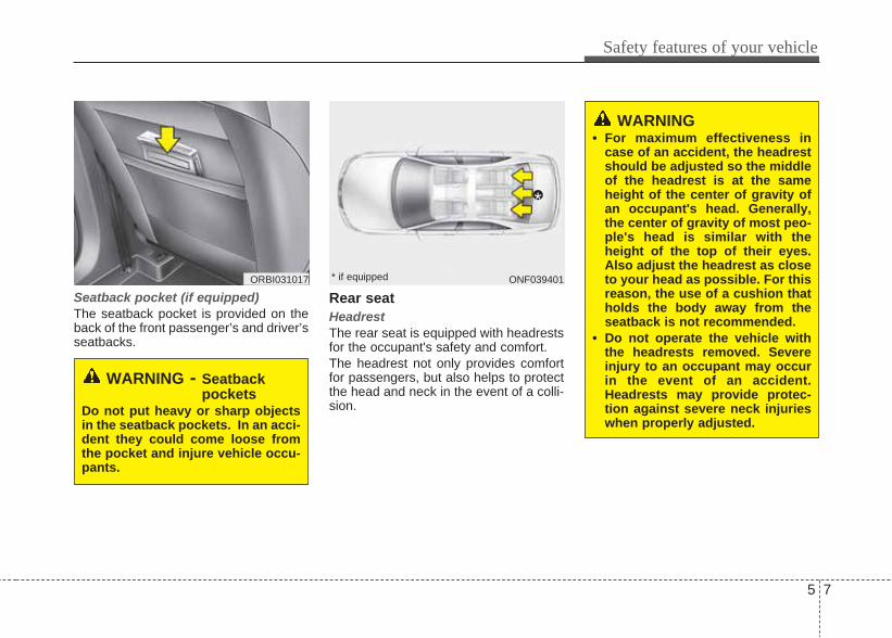
Seatback pocket (if equipped)The seatback pocket is provided on theback of the front passenger’s and driver’sseatbacks.
Rear seatHeadrestThe rear seat is equipped with headrestsfor the occupant's safety and comfort. The headrest not only provides comfortfor passengers, but also helps to protectthe head and neck in the event of a colli-sion.
WARNING - Seatbackpockets
Do not put heavy or sharp objectsin the seatback pockets. In an acci-dent they could come loose fromthe pocket and injure vehicle occu-pants.
ORBI031017
WARNING• For maximum effectiveness in
case of an accident, the headrestshould be adjusted so the middleof the headrest is at the sameheight of the center of gravity ofan occupant's head. Generally,the center of gravity of most peo-ple's head is similar with theheight of the top of their eyes.Also adjust the headrest as closeto your head as possible. For thisreason, the use of a cushion thatholds the body away from theseatback is not recommended.
• Do not operate the vehicle withthe headrests removed. Severeinjury to an occupant may occurin the event of an accident.Headrests may provide protec-tion against severe neck injurieswhen properly adjusted.
ONF039401
*
* if equipped

Safety features of your vehicle
85
Adjusting the height up and down (if equipped)To raise the headrest, pull it up to thedesired position (1). To lower the head-rest, push and hold the release button (2)on the headrest support and lower theheadrest to the desired position (3).
Removal (if equipped)To remove the headrest, raise it as far asit can go then press the release button(1) while pulling upward (2).To reinstall the headrest, put the head-rest poles (3) into the holes while press-ing the release button (1). Then adjust itto the appropriate height.
Armrest To use the armrest, swing down the arm-rest to the lowest position.
ORB030007
WARNINGMake sure the headrest locks inposition after adjusting it to proper-ly protect the occupants.
ORB030008 ORBI031032
5 9
Safety features of your vehicle
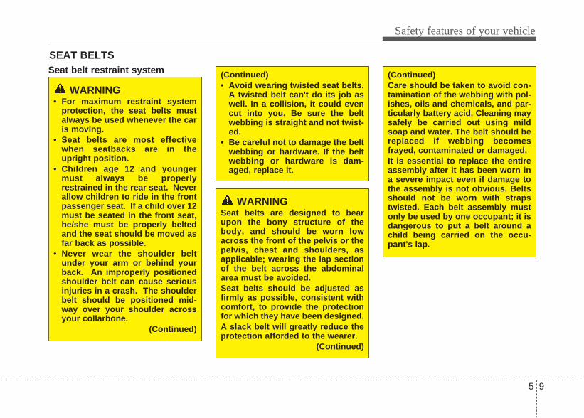
Seat belt restraint system
SEAT BELTS
WARNING• For maximum restraint system
protection, the seat belts mustalways be used whenever the caris moving.
• Seat belts are most effectivewhen seatbacks are in theupright position.
• Children age 12 and youngermust always be properlyrestrained in the rear seat. Neverallow children to ride in the frontpassenger seat. If a child over 12must be seated in the front seat,he/she must be properly beltedand the seat should be moved asfar back as possible.
• Never wear the shoulder beltunder your arm or behind yourback. An improperly positionedshoulder belt can cause seriousinjuries in a crash. The shoulderbelt should be positioned mid-way over your shoulder acrossyour collarbone.
(Continued)
WARNINGSeat belts are designed to bearupon the bony structure of thebody, and should be worn lowacross the front of the pelvis or thepelvis, chest and shoulders, asapplicable; wearing the lap sectionof the belt across the abdominalarea must be avoided.Seat belts should be adjusted asfirmly as possible, consistent withcomfort, to provide the protectionfor which they have been designed. A slack belt will greatly reduce theprotection afforded to the wearer.
(Continued)
(Continued)• Avoid wearing twisted seat belts.
A twisted belt can't do its job aswell. In a collision, it could evencut into you. Be sure the beltwebbing is straight and not twist-ed.
• Be careful not to damage the beltwebbing or hardware. If the beltwebbing or hardware is dam-aged, replace it.
(Continued)Care should be taken to avoid con-tamination of the webbing with pol-ishes, oils and chemicals, and par-ticularly battery acid. Cleaning maysafely be carried out using mildsoap and water. The belt should bereplaced if webbing becomesfrayed, contaminated or damaged. It is essential to replace the entireassembly after it has been worn ina severe impact even if damage tothe assembly is not obvious. Beltsshould not be worn with strapstwisted. Each belt assembly mustonly be used by one occupant; it isdangerous to put a belt around achild being carried on the occu-pant's lap.

Safety features of your vehicle
105
Seat belt warning (if equipped)As a reminder to the driver, the seat beltwarning light will blink for approximately6 seconds each time you turn the ignitionswitch ON regardless of belt fastening.If the driver’s seat belt is unfastened afterthe ignition switch is ON, the seat beltwarning light blinks again for approxi-mately 6 seconds. If the driver's seat belt is not fastenedwhen the ignition switch is turned ON orif it is unfastened after the ignition switchis ON, the seat belt warning chime willsound for approximately 6 seconds. Atthis time, if the seat belt is fastened, thechime will stop at once. (if equipped)
1GQA2083
WARNING• No modifications or additions
should be made by the userwhich will either prevent the seatbelt adjusting devices from oper-ating to remove slack, or preventthe seat belt assembly frombeing adjusted to remove slack.
• When you fasten the seat belt, becareful not to latch the seat belt inbuckles of other seat. It's very dan-gerous and you may not be pro-tected by the seat belt properly.
• Do not unfasten the seat belt anddo not fasten and unfasten theseat belt repeatedly while driving.This could result in loss of con-trol, and an accident causingdeath, serious injury, or propertydamage.
• When fastening the seat belt,make sure that the seat belt doesnot pass over objects that arehard or can break easily.
• Make sure there is nothing in thebuckle. The seat belt may not befastened securely.
5 11
Safety features of your vehicle
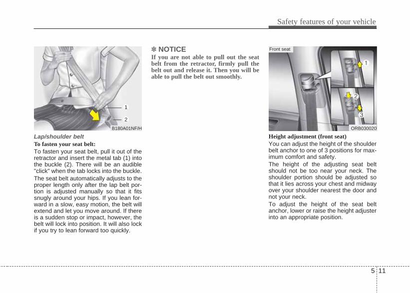
Lap/shoulder beltTo fasten your seat belt:To fasten your seat belt, pull it out of theretractor and insert the metal tab (1) intothe buckle (2). There will be an audible"click" when the tab locks into the buckle.The seat belt automatically adjusts to theproper length only after the lap belt por-tion is adjusted manually so that it fitssnugly around your hips. If you lean for-ward in a slow, easy motion, the belt willextend and let you move around. If thereis a sudden stop or impact, however, thebelt will lock into position. It will also lockif you try to lean forward too quickly.
✽ NOTICEIf you are not able to pull out the seatbelt from the retractor, firmly pull thebelt out and release it. Then you will beable to pull the belt out smoothly.
Height adjustment (front seat)You can adjust the height of the shoulderbelt anchor to one of 3 positions for max-imum comfort and safety.The height of the adjusting seat beltshould not be too near your neck. Theshoulder portion should be adjusted sothat it lies across your chest and midwayover your shoulder nearest the door andnot your neck.To adjust the height of the seat beltanchor, lower or raise the height adjusterinto an appropriate position.
ORB030020
Front seat
B180A01NF/H
1
2

Safety features of your vehicle
125
To raise the height adjuster, pull it up (1).To lower it, push it down (3) while press-ing the height adjuster button (2).Release the button to lock the anchorinto position. Try sliding the heightadjuster to make sure that it has lockedinto position.
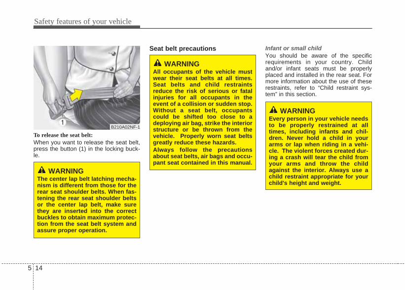
To release the seat belt:The seat belt is released by pressing therelease button (1) in the locking buckle.When it is released, the belt should auto-matically draw back into the retractor.If this does not happen, check the belt tobe sure it is not twisted, then try again.
B200A02NF/H
WARNINGYou should place the lap belt por-tion as low as possible and snuglyacross your hips, not on yourwaist. If the lap belt is located toohigh on your waist, it may increasethe chance of injury in the event ofa collision. Both arms should notbe under or over the belt. Rather,one should be over and the otherunder, as shown in the illustration. Never wear the seat belt under thearm nearest the door.
B210A01NF/H
WARNING• Verify the shoulder belt anchor is
locked into position at the appro-priate height. Never position theshoulder belt across your neck orface. Improperly positioned seatbelts can cause serious injuriesin an accident.
• Failure to replace seat belts afteran accident could leave you withdamaged seat belts that will notprovide protection in the event ofanother collision leading to per-sonal injury or death. Replaceyour seat belts after being in anaccident as soon as possible.

5 13
Safety features of your vehicle
Lap belt (if equipped)To fasten your seat belt:To fasten a 2-point static type belt, insertthe metal tab (1) into the locking buckle(2). There will be an audible "click" whenthe tab locks into the buckle. Check tomake sure the belt is properly locked andthat the belt is not twisted.
With a 2-point static type seat belt, thelength must be adjusted manually so itfits snugly around your body. Fasten thebelt and pull on the loose end to tighten.The belt should be placed as low as pos-sible on your hips, not on your waist. Ifthe belt is too high, it could increase thepossibility of your being injured in anaccident.
When using the rear center seat belt, thebuckle with the “CENTER” mark must beused.
OHM039105N
B220B01NF
Too high
Shorten Correct
OVI039066
Lengthen
Shorten
ORBC030009
Safety features of your vehicle
145
To release the seat belt:When you want to release the seat belt,press the button (1) in the locking buck-le.
Seat belt precautions Infant or small childYou should be aware of the specificrequirements in your country. Childand/or infant seats must be properlyplaced and installed in the rear seat. Formore information about the use of theserestraints, refer to “Child restraint sys-tem” in this section.
B210A02NF-1
WARNINGThe center lap belt latching mecha-nism is different from those for therear seat shoulder belts. When fas-tening the rear seat shoulder beltsor the center lap belt, make surethey are inserted into the correctbuckles to obtain maximum protec-tion from the seat belt system andassure proper operation.
WARNINGEvery person in your vehicle needsto be properly restrained at alltimes, including infants and chil-dren. Never hold a child in yourarms or lap when riding in a vehi-cle. The violent forces created dur-ing a crash will tear the child fromyour arms and throw the childagainst the interior. Always use achild restraint appropriate for yourchild's height and weight.
WARNINGAll occupants of the vehicle mustwear their seat belts at all times.Seat belts and child restraintsreduce the risk of serious or fatalinjuries for all occupants in theevent of a collision or sudden stop.Without a seat belt, occupantscould be shifted too close to adeploying air bag, strike the interiorstructure or be thrown from thevehicle. Properly worn seat beltsgreatly reduce these hazards. Always follow the precautionsabout seat belts, air bags and occu-pant seat contained in this manual.

5 15
Safety features of your vehicle
✽ NOTICESmall children are best protected frominjury in an accident when properlyrestrained in the rear seat by a childrestraint system that meets the require-ments of the Safety Standards of yourcountry. Before buying any childrestraint system, make sure that it has alabel certifying that it meets SafetyStandards of your country. The restraintmust be appropriate for your child'sheight and weight. Check the label onthe child restraint for this information.Refer to “Child restraint system” in thissection.
Larger childrenChildren who are too large for childrestraint systems should always occupythe rear seat and use the availablelap/shoulder belts. The lap portionshould be fastened snug on the hips andas low as possible. Check belt fit period-ically. A child's squirming could put thebelt out of position. Children are affordedthe most safety in the event of an acci-dent when they are restrained by a prop-er restraint system in the rear seat. If alarger child (over age 12) must be seatedin the front seat, the child should besecurely restrained by the availablelap/shoulder belt and the seat should beplaced in the rearmost position. Childrenage 12 and under should be restrainedsecurely in the rear seat. NEVER place achild age 12 and under in the front seat.NEVER place a rear facing child seat inthe front seat of a vehicle.If the shoulder belt portion slightly touch-es the child’s neck or face, try placing thechild closer to the center of the vehicle. Ifthe shoulder belt still touches their faceor neck they need to be returned to achild restraint system.
WARNING - Shoulder beltson small children
• Never allow a shoulder belt to bein contact with a child’s neck orface while the vehicle is inmotion.
• If seat belts are not properly wornand adjusted on children, there isa risk of death or serious injury.

Safety features of your vehicle
165
Pregnant womenThe use of a seat belt is recommendedfor pregnant women to lessen thechance of injury in an accident. When aseat belt is used, the lap belt portionshould be placed as low and snugly aspossible on the hips, not across theabdomen. For specific recommenda-tions, consult a physician.
Injured personA seat belt should be used when aninjured person is being transported.When this is necessary, you should con-sult a physician for recommendations.
One person per beltTwo people (including children) shouldnever attempt to use a single seat belt.This could increase the severity ofinjuries in case of an accident.
Do not lie downTo reduce the chance of injuries in theevent of an accident and to achieve max-imum effectiveness of the restraint sys-tem, all passengers should be sitting upand the front seats should be in anupright position when the car is moving.A seat belt cannot provide proper protec-tion if the person is lying down in the rearseat or if the front seat is in a reclinedposition.
WARNING - Pregnantwomen
Pregnant women must never placethe lap portion of the safety beltover the area of the abdomenwhere the fetus is located or abovethe abdomen where the belt couldcrush the fetus during an impact.
WARNINGRiding with a reclined seatbackincreases your chance of seriousor fatal injuries in the event of a col-lision or sudden stop. The protec-tion of your restraint system (seatbelts and air bags) is greatlyreduced by reclining your seat.Seat belts must be snug againstyour hips and chest to work prop-erly. The more the seatback isreclined, the greater the chancethat an occupant's hips will slideunder the lap belt causing seriousinternal injuries or the occupant'sneck could strike the shoulder belt.Drivers and passengers shouldalways sit well back in their seats,properly belted, and with the seat-backs upright.
5 17
Safety features of your vehicle
Care of seat beltsSeat belt systems should never be dis-assembled or modified. In addition, careshould be taken to assure that seat beltsand belt hardware are not damaged byseat hinges, doors or other abuse.
Periodic inspectionAll seat belts should be inspected peri-odically for wear or damage of any kind.Any damaged parts should be replacedas soon as possible.
Keep belts clean and drySeat belts should be kept clean and dry.If belts become dirty, they can becleaned by using a mild soap solutionand warm water. Bleach, dye, strongdetergents or abrasives should not beused because they may damage andweaken the fabric.
When to replace seat beltsEntire in-use seat belt assembly orassemblies should be replaced if thevehicle has been involved in an accident.This should be done even if no damageis visible. We recommend that additionalquestions concerning seat belt operationshould be directed to an authorizedHYUNDAI dealer.
WARNING When you return the rear seatbackto its upright position after the rearseatback was folded down, be care-ful not to damage the seat belt web-bing or buckle. Be sure that thewebbing or buckle does not getcaught or pinched in the rear seat.A seat belt with damaged webbingor buckle will not be as strong andcould possibly fail during a colli-sion or sudden stop, resulting inserious injury.

Safety features of your vehicle
185
Children riding in the car should sit in therear seat and must always be properlyrestrained to minimize the risk of injury inan accident, sudden stop or suddenmaneuver. According to accident statis-tics, children are safer when properlyrestrained in the rear seats than in thefront seat. Larger children not in a childrestraint should use one of the seat beltsprovided.You should be aware of the specificrequirements in your country. Childand/or infant safety seats must be prop-erly placed and installed in the rear seat.You must use a commercially availablechild restraint system that meets therequirements of the Safety Standards ofyour country.Child restraint systems are designed tobe secured in vehicle seats by lap beltsor the lap belt portion of a lap/shoulderbelt.Children could be injured or killed in acrash if their restraints are not properlysecured. For small children and babies, achild seat or infant seat must be used.
Before buying a particular child restraintsystem, make sure it fits your car seatand seat belts, and fits your child. Followall the instructions provided by the man-ufacturer when installing the childrestraint system.
CHILD RESTRAINT SYSTEM
WARNING• A child restraint system must be
placed in the rear seat. Neverinstall a child or infant seat on thefront passenger's seat. Should anaccident occur and cause thepassenger-side air bag to deploy,it could severely injure or kill aninfant or child seated in an infantor child seat. Thus only use achild restraint in the rear seat ofyour vehicle.
• A seat belt or child restraint sys-tem can become very hot if it isleft in a closed vehicle on a sunnyday, even if the outside tempera-ture does not feel hot. Be sure tocheck the seat cover and bucklesbefore placing a child there.
• When the child restraint systemis not in use, store it in the lug-gage area or fasten it with a seatbelt so that it will not be thrownforward in the case of a suddenstop or an accident.
• Children may be seriouslyinjured or killed by an inflating airbag. All children, even those toolarge for child restraints, mustride in the rear seat.

5 19
Safety features of your vehicle
WARNINGTo reduce the chance of serious orfatal injuries:• Children of all ages are safer
when restrained in the rear seat.A child riding in the front passen-ger seat can be forcefully struckby an inflating air bag resulting inserious or fatal injuries.
• Always follow the child restraintsystem manufacturer’s instruc-tions for installation and use ofthe child restraint.
• Always make sure the child seatis secured properly in the car andyour child is securely restrainedin the child seat.
• Never hold a child in your arms orlap when riding in a vehicle. Theviolent forces created during acrash will tear the child from yourarms and throw the child againstthe car’s interior.
• Never put a seat belt over your-self and a child. During a crash,the belt could press deep into thechild causing serious internalinjuries.
(Continued)
(Continued)• Never leave children unattended
in a vehicle – not even for a shorttime. The car can heat up veryquickly, resulting in seriousinjuries to children inside. Evenvery young children may inadver-tently cause the vehicle to move,entangle themselves in the win-dows, or lock themselves or oth-ers inside the vehicle.
• Never allow two children, or anytwo persons, to use the sameseat belt.
• Children often squirm and repo-sition themselves improperly.Never let a child ride with theshoulder belt under their arm orbehind their back. Always prop-erly position and secure childrenin the rear seat.
• Never allow a child to stand-up orkneel on the seat or floor of amoving vehicle. During a colli-sion or sudden stop, the childcan be violently thrown againstthe vehicle’s interior, resulting inserious injury.
(Continued)
(Continued)• Never use an infant carrier or a
child safety seat that "hooks"over a seatback, it may not pro-vide adequate security in an acci-dent.
• Seat belts can become very hot,especially when the car is parkedin direct sunlight. Always checkseat belt buckles before fasten-ing them over a child.
• After an accident, have the childrestraint system, seat belt, tetheranchor and lower anchorchecked. We recommend to haveit done by an authorizedHYUNDAI dealer.
• If there is not enough space toplace the child restraint systembecause of the driver's seat,install the child restraint systemin the rear right seat.

Safety features of your vehicle
205
Using a child restraint systemFor small children and babies, the use ofa child seat or infant seat is required.This child seat or infant seat should be ofappropriate size for the child and shouldbe installed in accordance with the man-ufacturer's instructions.
For safety reasons, we recommend thatthe child restraint system be used in therear seats.
CRS09
ORB030026
Forward-facing child restraint system
Rearward-facing child restraint system
WARNINGNever place a rear-facing childrestraint in the front passengerseat, because of the danger that aninflating passenger-side air bagcould impact the rear-facing childrestraint and kill the child.
WARNING - Child seatinstallation
• A child can be seriously injuredor killed in a collision if the childrestraint is not properly anchoredto the car and the child is notproperly restrained in the childrestraint. Before installing thechild restraint system, read theinstructions supplied by the childrestraint system manufacturer.
• If the seat belt does not operateas described in this section, havethe system checked immediately.We recommend to have it doneby an authorized HYUNDAI deal-er.
• Failure to observe this manual'sinstructions regarding childrestraint systems and theinstructions provided with thechild restraint system couldincrease the chance and/orseverity of injury in an accident.

5 21
Safety features of your vehicle
Installing a child restraint systemwith a lap belt (on the center rearseat)
To install a child restraint system on thecenter rear seats, do the following:1. Place the child restraint system on the
center rear seat.2. Extend the latch plate tongue of the
lap belt.3. Route the lap belt through the restraint
according to the seat manufacturer’sinstructions.
4. Buckle the seat belt and adjust the lapbelt for a snug hold on the childrestraint by pulling on the loose end ofthe belt. After installation of the childrestraint system, try to move it in alldirections to be sure the child restraintsystem is securely installed.
Installing a child restraint system bylap/shoulder belt
To install a child restraint system on theoutboard or center rear seats, do the fol-lowing:1. Place the child restraint system in the
seat and route the lap/shoulder beltaround or through the restraint, follow-ing the restraint manufacturer’sinstructions. Be sure the seat beltwebbing is not twisted.
2. Fasten the lap/shoulder belt latch intothe buckle. Listen for the distinct“click” sound.
Position the release button so that it iseasy to access in case of an emergency.
E2BLD347 E2MS103005 OEN036101
Safety features of your vehicle
225
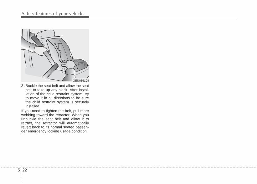
3. Buckle the seat belt and allow the seatbelt to take up any slack. After instal-lation of the child restraint system, tryto move it in all directions to be surethe child restraint system is securelyinstalled.
If you need to tighten the belt, pull morewebbing toward the retractor. When youunbuckle the seat belt and allow it toretract, the retractor will automaticallyrevert back to its normal seated passen-ger emergency locking usage condition.
OEN036104

5 23
Safety features of your vehicle
(1) Driver’s front air bag*(2) Passenger’s front air bag*(3) Side air bag*(4) Curtain air bag** : if equipped
AIR BAG - SUPPLEMENTAL RESTRAINT SYSTEM (IF EQUIPPED)
WARNINGEven in vehicles with air bags, youand your passengers must alwayswear the safety belts provided inorder to minimize the risk andseverity of injury in the event of acollision or rollover.
OTF030032R
* The actual air bags in the vehicle may differ from the illustration.

Safety features of your vehicle
245
How does the air bag systemoperate • Air bags are activated (able to inflate if
necessary) only when the ignitionswitch is turned to the ON or STARTposition.
• Air bags inflate instantly in the event ofa serious frontal or side collision (ifequipped with side air bag or curtainair bag) in order to help protect theoccupants from serious physical injury.
• There is no single speed at which theair bags will inflate. Generally, air bags are designed toinflate based upon the severity of a col-lision and its direction. These two fac-tors determine whether the sensorsproduce an electronic deployment/inflation signal.
• Air bag deployment depends on anumber of factors including vehiclespeed, angles of impact and the densi-ty and stiffness of the vehicles orobjects which your vehicle hits in thecollision. The determining factors arenot limited to those mentioned above.
• The front air bags will completelyinflate and deflate in an instant. It is virtually impossible for you to seethe air bags inflate during an accident.
It is much more likely that you will sim-ply see the deflated air bags hangingout of their storage compartments afterthe collision.
• In order to help provide protection in asevere collision, the air bags mustinflate rapidly. The speed of air baginflation is a consequence of theextremely short time in which a collisionoccurs and the need to inflate the airbag between the occupant and thevehicle structures before the occupantimpacts those structures. This speed ofinflation reduces the risk of serious orlife-threatening injuries in a severe col-lision and is thus a necessary part of airbag design.However, air bag inflation can alsocause injuries which can include facialabrasions, bruises and broken bonesbecause the inflation speed also caus-es the air bags to expand with a greatdeal of force.
• There are even circumstancesunder which contact with the steer-ing wheel air bag can cause fatalinjuries, especially if the occupantis positioned excessively close tothe steering wheel.
WARNING• To avoid severe personal injury
or death caused by deploying airbags in a collision, the drivershould sit as far back from thesteering wheel air bag as possi-ble (at least 250 mm (10 inches)away). The front passengersshould always move their seatsas far back as possible and sitback in their seat.
• Air bags inflate instantly in theevent of collision, and passen-gers may be injured by the airbag expansion force if they arenot in proper position.
• Air bag inflation may causeinjuries including facial or bodilyabrasions, injuries from brokenglasses or burns.

5 25
Safety features of your vehicle
Noise and smokeWhen the air bags inflate, they make aloud noise and they leave smoke andpowder in the air inside of the vehicle.This is normal and is a result of the igni-tion of the air bag inflator. After the airbag inflates, you may feel substantial dis-comfort in breathing due to the contact ofyour chest with both the seat belt and theair bag, as well as from breathing thesmoke and powder. Open your doorsand/or windows as soon as possibleafter impact in order to reduce dis-comfort and prevent prolonged expo-sure to the smoke and powder. Though the smoke and powder are non-toxic, they may cause irritation to the skin(eyes, nose and throat, etc). If this is thecase, wash and rinse with cold waterimmediately and consult a doctor if thesymptom persists.
Do not install a child restraint on thefront passenger’s seat.Never place a rear-facing child restraintin the front passenger’s seat. If the airbag deploys, it would impact the rear-fac-ing child restraint, causing serious orfatal injury.In addition, do not place front-facing childrestraints in the front passenger’s seateither. If the front passenger air baginflates, it could cause serious or fatalinjuries to the child.
1JBH3051
WARNINGWhen the air bags deploy, the airbag related parts in the steeringwheel and/or instrument paneland/or in both sides of the roof railsabove the front and rear doors arevery hot. To prevent injury, do nottouch the air bag storage area’sinternal components immediatelyafter an air bag has inflated.
WARNING• Extreme Hazard! Do not use a
rearward facing child restraint ona seat protected by an air bag infront of it!
• Never put a child restraint in thefront passenger’s seat. If thefront passenger air bag inflates, itcan cause serious or fatalinjuries.
• When children are seated in therear outboard seats of a vehicleequipped with side and/or curtainair bags, be sure to install thechild restraint system as far awayfrom the door side as possible,and securely lock the childrestraint system in position. Inflation of side and/or curtain airbags could cause serious injuryor death to an infant or child.

Safety features of your vehicle
265
Air bag warning lightThe purpose of the air bag warning lightin your instrument panel is to alert you ofa potential problem with your air bag -Supplemental Restraint System (SRS).When the ignition switch is turned ON,the warning light should illuminate forapproximately 6 seconds, then go off.Have the system checked if:• The light does not turn on briefly when
you turn the ignition ON.• The light stays on after illuminating for
approximately 6 seconds. • The light comes on while the vehicle is
in motion. • The light blinks when the ignition
switch is in ON position.
SRS components and functionsThe SRS consists of the following com-ponents:1. Driver's front air bag module*2. Passenger's front air bag module*3. Side air bag modules*4. Curtain air bag modules*5. Air bag warning light6. SRS control module (SRSCM)7. Front impact sensors8. Side impact sensors**: if equipped
The SRSCM continually monitors allSRS components while the ignitionswitch is ON to determine if a crashimpact is severe enough to require airbag deployment.The SRS air bag warning light " " onthe instrument panel will illuminate forabout 6 seconds after the ignition switchis turned to the ON position, after whichthe SRS air bag warning light " "should go out.
W7-147 ORBI031033WARNING
If any of the following conditionsoccurs, this indicates a malfunc-tion of the SRS. Have air bag sys-tem checked as soon as possible.We recommend that you have itchecked by an authorized Hyundaidealer.• The light does not turn on briefly
when you turn the ignition ON.• The light stays on after illuminat-
ing for approximately 6 seconds.• The light comes on while the
vehicle is in motion.• The light blinks when the ignition
switch is in ON position.

5 27
Safety features of your vehicle
The front air bag modules are locatedboth in the center of the steering wheeland in the front passenger's panel abovethe glove box. When the SRSCM detectsa sufficiently severe impact to the front ofthe vehicle, it will automatically deploythe front air bags.
Upon deployment, tear seams moldeddirectly into the pad covers will separateunder pressure from the expansion of theair bags. Further opening of the coversthen allows full inflation of the air bags.
A fully inflated air bag, in combinationwith a properly worn seat belt, slows thedriver's or the passenger's forwardmotion, reducing the risk of head andchest injury.
After complete inflation, the air bagimmediately starts deflating, enabling thedriver to maintain forward visibility andthe ability to steer or operate other con-trols.
B240B01L/H
Driver’s front air bag (1)
B240B02L/H B240B03L/H
Driver’s front air bag (2) Driver’s front air bag (3)

Safety features of your vehicle
285
WARNING • Do not install or place any acces-
sories (drink holder, cassetteholder, sticker, etc.) on the frontpassenger's panel above theglove box in a vehicle with a pas-senger's air bag. Such objectsmay become dangerous projec-tiles and cause injury if the pas-senger's air bag inflates.
• When installing a container of liq-uid air freshener inside the vehi-cle, do not place it near theinstrument cluster nor on theinstrument panel surface. It may become a dangerous pro-jectile and cause injury if the pas-senger's air bag inflates.
B240B05L/H
Passenger’s front air bag
WARNING• If an air bag deploys, there may
be a loud noise followed by a finedust released in the vehicle.These conditions are normal andare not hazardous - the air bagsare packed in this fine powder.The dust generated during airbag deployment may cause skinor eye irritation as well as aggra-vate asthma for some persons.Always wash all exposed skinareas thoroughly with lukewarmwater and a mild soap after anaccident in which the air bagswere deployed.
• The SRS can function only whenthe ignition switch is in the ONposition. If the SRS " " warninglight does not illuminate, or con-tinuously remains on after illumi-nating for about 6 seconds whenthe ignition switch is turned tothe ON position, or after theengine is started, comes on whiledriving, the SRS is not workingproperly. If this occurs have yourvehicle inspected immediately.We recommend to have itinspected by an authorizedHyundai dealer.
(Continued)
(Continued)• Before you replace a fuse or dis-
connect a battery terminal, turnthe ignition switch to the LOCKposition and remove the ignitionkey. Never remove or replace theair bag related fuse(s) when theignition switch is in the ON posi-tion. Failure to heed this warningwill cause the SRS “ ” warninglight to illuminate.

5 29
Safety features of your vehicle
Driver's and passenger's front airbag Your vehicle is equipped with aSupplemental Restraint (Air Bag)System and the lap/shoulder belts atboth the driver and passenger seatingpositions. The indications of the system'spresence are the letters "AIR BAG"embossed on the air bag pad cover inthe steering wheel and the passenger'sside front panel pad above the glove box.
The SRS consists of air bags installedunder the pad covers in the center of thesteering wheel and the passenger's sidefront panel above the glove box.
The purpose of the SRS is to provide thevehicle's driver and/or the front passen-ger with additional protection than thatoffered by the seat belt system alone incase of a frontal impact of sufficientseverity.
ORBI031010
Driver’s front air bag
WARNINGAlways use seat belts and childrestraints – every trip, every time,everyone! Air bags inflate with con-siderable force and in the blink ofan eye. Seat belts help keep occu-pants in proper position to obtainmaximum benefit from the air bag.Even with air bags, improperly belt-ed and unbelted occupants can beseverely injured when the air baginflates. Always follow the precau-tions about seat belts, air bags andoccupant safety contained in thismanual. To reduce the chance of serious orfatal injuries and receive the maxi-mum safety benefit from yourrestraint system:• Never place a child in any child or
booster seat in the front seat.• ABC – Always Buckle Children in
the back seat. It is the safestplace for children of any age toride.
• Front and side air bags can injureoccupants improperly positionedin the front seats.
(Continued)
ORBI031011
Passenger’s front air bag

Safety features of your vehicle
305
(Continued)• Move your seat as far back as
practical from the front air bags,while still maintaining control ofthe vehicle.
• You and your passengers shouldnever sit or lean unnecessarilyclose to the air bags. Improperlypositioned drivers and passen-gers can be severely injured byinflating air bags.
• Never lean against the door orcenter console – always sit in anupright position.
• No objects should be placed overor near the air bag modules onthe steering wheel, instrumentpanel, and the front passenger'spanel above the glove box,because any such object couldcause harm if the vehicle is in acrash severe enough to causethe air bags to deploy.
• Do not tamper with or disconnectSRS wiring or other componentsof the SRS system. Doing socould result in injury, due to acci-dental deployment of the air bagsor by rendering the SRS inopera-tive.
(Continued)
(Continued)• If the SRS air bag warning light
“ ”remains illuminated whilethe vehicle is being driven, havethe air bag system inspected. Werecommend to have it inspectedby an authorized Hyundai dealer.
• Air bags can only be used once,replace the air bags immediately.We recommend to have itinspected by an authorizedHyundai dealer.
• The SRS is designed to deploythe front air bags only when animpact is sufficiently severe andwhen the impact angle is lessthan 30° from the forward longitu-dinal axis of the vehicle.Additionally, the air bags willonly deploy once. Seat beltsmust be worn at all times.
• Front air bags are not intended todeploy in side-impact, rear-impact or rollover crashes. Inaddition, front air bags will notdeploy in frontal crashes belowthe deployment threshold.
(Continued)
(Continued)• A child restraint system must
never be placed in the front seat.The infant or child could beseverely injured or killed by an airbag deployment in case of anaccident.
• Children age 12 and under mustalways be properly restrained inthe rear seat. Never allow chil-dren to ride in the front passen-ger seat. If a child over 12 mustbe seated in the front seat, he orshe must be properly belted andthe seat should be moved as farback as possible.
• For maximum safety protectionin all types of crashes, all occu-pants including the driver shouldalways wear their seat beltswhether or not an air bag is alsoprovided at their seating positionto minimize the risk of severeinjury or death in the event of acrash. Do not sit or lean unnec-essarily close to the air bag whilethe vehicle is in motion.
(Continued)

5 31
Safety features of your vehicle
Side impact air bag (if equipped)Your vehicle is equipped with a sideimpact air bag in each front seat. Thepurpose of the air bag is to provide thevehicle's driver and the front passengerwith additional protection than thatoffered by the seat belt alone.
The side impact air bags are designed todeploy only during certain side-impactcollisions, depending on the crash sever-ity, angle, speed and point of impact. Theside impact air bags are not designed todeploy in all side impact situations.
(Continued)• Sitting improperly or out of posi-
tion can result in serious or fatalinjury in a crash. All occupantsshould sit upright with the seatback in an upright position, cen-tered on the seat cushion withtheir seat belt on, legs comfort-ably extended and their feet onthe floor until the vehicle isparked and the ignition key isremoved.
• The SRS air bag system mustdeploy very rapidly to provideprotection in a crash. If an occu-pant is out of position because ofnot wearing a seat belt, the airbag may forcefully contact theoccupant causing serious or fatalinjuries.
ORBC030021
OYF039057N
Front
WARNINGDo not allow the passengers to leantheir heads or bodies onto doors,put their arms on the doors, stretchtheir arms out of the window, orplace objects between the doorsand passengers when they areseated on seats equipped with sideand/or curtain air bags.
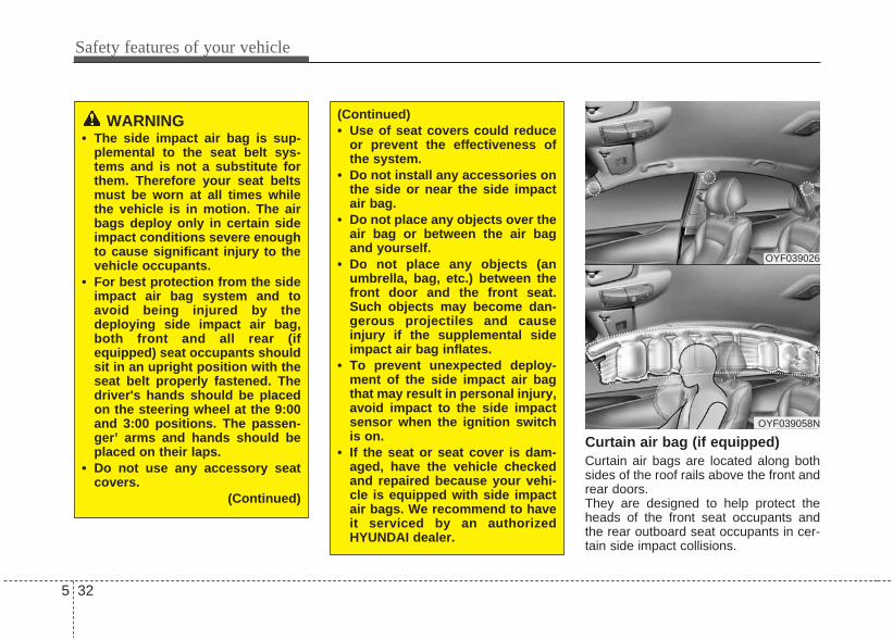
Safety features of your vehicle
325
Curtain air bag (if equipped)Curtain air bags are located along bothsides of the roof rails above the front andrear doors. They are designed to help protect theheads of the front seat occupants andthe rear outboard seat occupants in cer-tain side impact collisions.
WARNING• The side impact air bag is sup-
plemental to the seat belt sys-tems and is not a substitute forthem. Therefore your seat beltsmust be worn at all times whilethe vehicle is in motion. The airbags deploy only in certain sideimpact conditions severe enoughto cause significant injury to thevehicle occupants.
• For best protection from the sideimpact air bag system and toavoid being injured by thedeploying side impact air bag,both front and all rear (ifequipped) seat occupants shouldsit in an upright position with theseat belt properly fastened. Thedriver's hands should be placedon the steering wheel at the 9:00and 3:00 positions. The passen-ger’ arms and hands should beplaced on their laps.
• Do not use any accessory seatcovers.
(Continued)
(Continued)• Use of seat covers could reduce
or prevent the effectiveness ofthe system.
• Do not install any accessories onthe side or near the side impactair bag.
• Do not place any objects over theair bag or between the air bagand yourself.
• Do not place any objects (anumbrella, bag, etc.) between thefront door and the front seat.Such objects may become dan-gerous projectiles and causeinjury if the supplemental sideimpact air bag inflates.
• To prevent unexpected deploy-ment of the side impact air bagthat may result in personal injury,avoid impact to the side impactsensor when the ignition switchis on.
• If the seat or seat cover is dam-aged, have the vehicle checkedand repaired because your vehi-cle is equipped with side impactair bags. We recommend to haveit serviced by an authorizedHYUNDAI dealer.
OYF039026
OYF039058N

5 33
Safety features of your vehicle
The curtain air bags are designed todeploy only during certain side impactcollisions, depending on the crash sever-ity, angle, speed and impact. The curtainair bags are not designed to deploy in allside impact situations, collisions from thefront or rear of the vehicle or in mostrollover situations.
WARNING• In order for side and curtain air
bags to provide the best protec-tion, front seat occupants andoutboard rear occupants shouldsit in an upright position with theseat belts properly fastened.Importantly, children should sitin a proper child restraint systemin the rear seat.
• When children are seated in therear outboard seats, they must beseated in the proper childrestraint system. Make sure toposition the child restraint sys-tem as far away from the doorside as possible, and secure thechild restraint system in a lockedposition.
(Continued)
(Continued)• Do not allow the passengers to
lean their heads or bodies ontodoors, put their arms on thedoors, stretch their arms out ofthe window, or place objectsbetween the doors and passen-gers when they are seated onseats equipped with side and/orcurtain air bags.
• Never try to open or repair anycomponents of the side curtainair bag system. We recommendthat this be done by an author-ized HYUNDAI dealer.
Failure to follow the above instruc-tions can result in injury or death tothe vehicle occupants in an acci-dent.

Safety features of your vehicle
345
Why didn’t my air bag go off in acollision? (Inflation and non-infla-tion conditions of the air bag)There are many types of accidents inwhich the air bag would not beexpected to provide additional protec-tion. These include rear impacts, second orthird collisions in multiple impactaccidents, as well as low speedimpacts. In other words, just becauseyour vehicle is damaged and even if itis totally unusable, don’t be surprisedthat the air bags did not inflate.
Air bag collision sensors(1) SRS control module(2) Front impact sensor
(3) Side impact sensor
ORBI031013/ORBI031014/ORB030015/ORBI031018
1 2 3

5 35
Safety features of your vehicle
Air bag inflation conditionsFront air bags Front air bags are designed to inflate in afrontal collision depending on the intensi-ty, speed or angles of impact of the frontcollision.
1JBA3513/H
(Continued)• Problems may arise if the sensor
installation angles are changeddue to the deformation of thefront bumper, body or B and Cpillars where side collision sen-sors are installed. We recom-mend to have the vehiclechecked and repaired by anauthorized HYUNDAI dealer.
• Your vehicle has been designedto absorb impact and deploy theair bag(s) in certain collisions.Installing bumper guards orreplacing a bumper with non-genuine parts may adverselyaffect your vehicle’s collision andair bag deployment performance.
WARNING• Do not hit or allow any objects to
impact the locations where airbags or sensors are installed. This may cause unexpected airbag deployment, which couldresult in serious personal injuryor death.
• If the installation location orangle of the sensors is altered inany way, the air bags may deploywhen they should not or theymay not deploy when theyshould, causing severe injury ordeath. Therefore, do not try to performmaintenance on or around the airbag sensors. We recommend tohave the vehicle checked andrepaired by an authorizedHYUNDAI dealer.
(Continued)

Safety features of your vehicle
365
Side impact and curtain air bags (if equipped)Side impact and curtain air bags aredesigned to inflate when an impact isdetected by side collision sensorsdepending on the strength, speed orangles of impact resulting from a sideimpact collision.
Although the front air bags (driver’s andfront passenger’s air bags) are designedto inflate only in frontal collisions, theyalso may inflate in other types of colli-sions if the front impact sensors detect asufficient impact. Side impact and curtainair bags are designed to inflate only inside impact collisions, but they mayinflate in other collisions if the sideimpact sensors detect a sufficientimpact.If the vehicle chassis is impacted bybumps or objects on unimproved roads,the air bags may deploy. Drive carefullyon unimproved roads or on surfaces notdesigned for vehicle traffic to preventunintended air bag deployment.
Air bag non-inflation conditions• In certain low-speed collisions the air
bags may not deploy. The air bags aredesigned not to deploy in such casesbecause they may not provide benefitsbeyond the protection of the seat beltsin such collisions.
1JBA3515/H
1JBA3514
1LDA2057
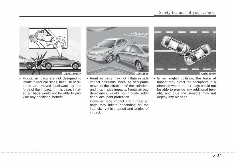
5 37
Safety features of your vehicle
• Frontal air bags are not designed toinflate in rear collisions, because occu-pants are moved backward by theforce of the impact. In this case, inflat-ed air bags would not be able to pro-vide any additional benefit.
• Front air bags may not inflate in sideimpact collisions, because occupantsmove to the direction of the collision,and thus in side impacts, frontal air bagdeployment would not provide addi-tional occupant protection.However, side impact and curtain airbags may inflate depending on theintensity, vehicle speed and angles ofimpact.
• In an angled collision, the force ofimpact may direct the occupants in adirection where the air bags would notbe able to provide any additional ben-efit, and thus the sensors may notdeploy any air bags.
OBH0380601JBA3516OBH038058/H
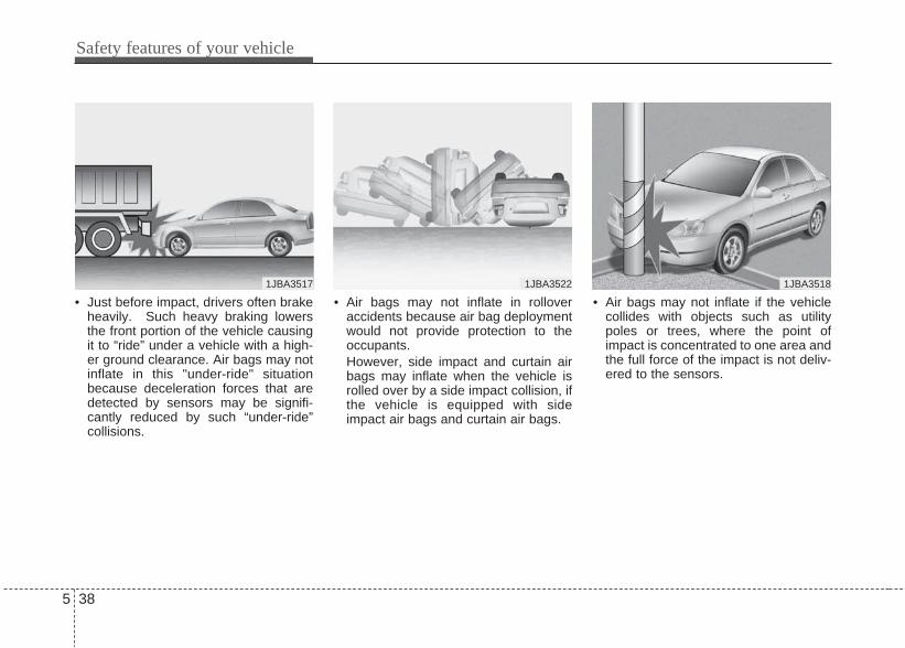
Safety features of your vehicle
385
• Just before impact, drivers often brakeheavily. Such heavy braking lowersthe front portion of the vehicle causingit to “ride” under a vehicle with a high-er ground clearance. Air bags may notinflate in this "under-ride" situationbecause deceleration forces that aredetected by sensors may be signifi-cantly reduced by such “under-ride”collisions.
• Air bags may not inflate in rolloveraccidents because air bag deploymentwould not provide protection to theoccupants.However, side impact and curtain airbags may inflate when the vehicle isrolled over by a side impact collision, ifthe vehicle is equipped with sideimpact air bags and curtain air bags.
• Air bags may not inflate if the vehiclecollides with objects such as utilitypoles or trees, where the point ofimpact is concentrated to one area andthe full force of the impact is not deliv-ered to the sensors.
1JBA3517 1JBA3522 1JBA3518
5 39
Safety features of your vehicle
SRS CareThe SRS is virtually maintenance-freeand so there are no parts you can safelyservice by yourself. If the SRS air bagwarning light does not illuminatewhen you turn the ignition ON, or if it con-tinuously remains on, have your vehicleimmediately inspected. We recommendto have it inspected by an authorizedHYUNDAI dealer.
WARNING• Modification to SRS components
or wiring, including the additionof any kind of badges to the padcovers or modifications to thebody structure, can adverselyaffect SRS performance and leadto possible injury.
• For cleaning the air bag pad cov-ers, use only a soft, dry cloth orone which has been moistenedwith plain water. Solvents orcleaners could adversely affectthe air bag covers and properdeployment of the system.
• No objects should be placed overor near the air bag modules on thesteering wheel, instrument panel,and the front passenger's panelabove the glove box, because anysuch object could cause harm if thevehicle is in a crash severe enoughto cause the air bags to inflate.
(Continued)
(Continued)• If the air bags inflate, they must
be replaced. We recommend tohave it replaced by an authorizedHYUNDAI dealer.
• Do not tamper with or disconnectSRS wiring, or other componentsof the SRS system. Doing socould result in injury, due to acci-dental inflation of the air bags orby rendering the SRS inopera-tive.
• If components of the air bag sys-tem must be discarded, or if thevehicle must be scrapped, cer-tain safety precautions must beobserved. An authorizedHYUNDAI dealer knows theseprecautions and can give you thenecessary information. Failure tofollow these precautions and pro-cedures could increase the riskof personal injury.
• If your car was flooded and hassoaked carpeting or water on theflooring, you shouldn't try to startthe engine; we recommend thatyou contact an authorizedHyundai dealer.

Safety features of your vehicle
405
Additional safety precautions• Never let passengers ride in the
cargo area or on top of a folded-down back seat. All occupants shouldsit upright, fully back in their seats withtheir seat belts on and their feet on thefloor.
• Passengers should not move out ofor change seats while the vehicle ismoving. A passenger who is not wear-ing a seat belt during a crash or emer-gency stop can be thrown against theinside of the vehicle, against otheroccupants, or out of the vehicle.
• Each seat belt is designed torestrain one occupant. If more thanone person uses the same seat belt,they could be seriously injured or killedin a collision.
• Do not use any accessories on seatbelts. Devices claiming to improveoccupant comfort or reposition the seatbelt can reduce the protection providedby the seat belt and increase thechance of serious injury in a crash.
• Passengers should not place hardor sharp objects between them-selves and the air bags. Carryinghard or sharp objects on your lap or inyour mouth can result in injuries if anair bag inflates.
• Keep occupants away from the airbag covers. All occupants should situpright, fully back in their seats withtheir seat belts on and their feet on thefloor. If occupants are too close to theair bag covers, they could be injured ifthe air bags inflate.
• Do not attach or place objects on ornear the air bag covers. Any objectattached to or placed on the front orside air bag covers could interfere withthe proper operation of the air bags.
• Do not modify the front seats.Modification of the front seats couldinterfere with the operation of the sup-plemental restraint system sensingcomponents or side air bags.
• Do not place items under the frontseats. Placing items under the frontseats could interfere with the operationof the supplemental restraint systemsensing components and wiring har-nesses.
• Never hold an infant or child onyour lap. The infant or child could beseriously injured or killed in the eventof a crash. All infants and childrenshould be properly restrained in appro-priate child safety seats or seat belts inthe rear seat.
Adding equipment to or modifyingyour air bag-equipped vehicleIf you modify your vehicle by changingyour vehicle's frame, bumper system,front end or side sheet metal or rideheight, this may affect the operation ofyour vehicle's air bag system.
WARNING• Sitting improperly or out of posi-
tion can cause occupants to beshifted too close to a deployingair bag, strike the interior struc-ture or be thrown from the vehi-cle resulting in serious injury ordeath.
• Always sit upright with the seat-back in an upright position, cen-tered on the seat cushion withyour seat belt on, legs comfort-ably extended and your feet onthe floor.

5 41
Safety features of your vehicle
Air bag warning label (if equipped)Air bag warning labels are attached toalert the passengers of potential risk ofair bag system.Note that these government warningsfocus on the risk to children, we alsowant you to be aware of the risks whichadults are exposed to. Those have beendescribed in previous pages.
ORBI031016
*
* if equipped


Keys / 6-3Smart key / 6-5Remote keyless entry / 6-9Door locks / 6-12Trunk / 6-16Windows / 6-18Hood / 6-22Fuel filler lid / 6-24Steering wheel / 6-27Mirrors / 6-29Instrument cluster / 6-33
Rear parking assist system / 6-56Rearview camera / 6-59Hazard warning flasher / 6-60Lighting / 6-61Wipers and washers / 6-66Interior light / 6-68Defroster / 6-70Manual climate control system / 6-71Automatic climate control system / 6-80Windshield defrosting and defogging / 6-87Storage compartment / 6-90
6Features of your vehicle
Interior features / 6-92Audio system / 6-97
6 Features of your vehicle

Key operationsUsed to start the engine, lock and unlockthe doors.
Immobilizer systemYour vehicle may be equipped with anelectronic engine immobilizer system toreduce the risk of unauthorized vehicleuse. Your immobilizer system is comprised ofa small transponder in the ignition keyand electronic devices inside the vehicle.With the immobilizer system, wheneveryou insert your ignition key into the igni-tion switch and turn it to ON, it checksand determines and verifies if the ignitionkey is valid or not.If the key is determined to be valid, theengine will start.If the key is determined to be invalid, theengine will not start.
KEYS
WARNING - Ignition keyLeaving children unattended in avehicle with the ignition key is dan-gerous even if the key is not in theignition switch. Children copyadults and they could place the keyin the ignition switch. The ignitionkey would enable children to oper-ate power windows or other con-trols, or even make the vehiclemove, which could result in seriousbodily injury or even death. Neverleave the keys in your vehicle withunsupervised children.
WARNINGWe recommend that you use partsfor replacement from an authorizedHYUNDAI dealer. If an aftermarketkey is used, the ignition switch maynot return to ON after START. Ifthis happens, the starter will con-tinue to operate causing damage tothe starter motor and possible firedue to excessive current in thewiring.
OED036001A
Features of your vehicle
36

Features of your vehicle
46
To activate the immobilizer system:Turn the ignition key to the OFF position.The immobilizer system activates auto-matically. Without a valid ignition key foryour vehicle, the engine will not start.
To deactivate the immobilizer sys-tem:Insert the ignition key into the key cylin-der and turn it to the ON position.
✽ NOTICEWhen starting the engine, do not use thekey with other immobilizer keys around.Otherwise the engine may not start ormay stop soon after it starts. Keep eachkey separate in order to avoid a startingmalfunction.
✽ NOTICEIf you need additional keys or lose yourkeys, we recommend that you consult anauthorized HYUNDAI dealer.
WARNINGIn order to prevent theft of yourvehicle, do not leave spare keysanywhere in your vehicle. Yourimmobilizer password is a cus-tomer unique password and shouldbe kept confidential. Do not leavethis number anywhere in your vehi-cle.
CAUTIONThe transponder in your ignitionkey is an important part of theimmobilizer system. It is designedto give years of trouble-free serv-ice, however you should avoidexposure to moisture, static elec-tricity and rough handling.Immobilizer system malfunctioncould occur.
CAUTIONDo not put metal accessories nearthe ignition switch.The engine may not start becausethe metal accessories may interruptthe transponder signal from trans-mitting normally.
CAUTIONDo not change, alter or adjust theimmobilizer system because itcould cause the immobilizer sys-tem to malfunction. We recommendthat the system be serviced by anauthorized HYUNDAI dealer. Malfunctions caused by improperalterations, adjustments or modifi-cations to the immobilizer systemare not covered by your vehiclemanufacturer warranty.

6 5
Features of your vehicle
With a smart key, you can lock or unlocka door (and trunk) and even start theengine without inserting the key.The functions of buttons on a smart keyare similar to the remote keyless entry.(Refer to the “Remote keyless entry” inthis section.)
To remove the mechanical key, pressand hold the release button and removethe mechanical key.To reinstall the mechanical key, put thekey into the hole and push it until a clicksound is heard.
Smart key functionsWith the smart key, you can lock andunlock the vehicle doors (and trunk), andthe smart key enables starting of theengine as well. Detailed information fol-lows:
SMART KEY (IF EQUIPPED)
OYF049302N OYF049303N

Locking Using the door handle switchPressing the button of the front outsidedoor handles with all doors (and trunk)closed and any door unlock, locks all thedoors (and trunk). If all doors and trunkare closed, the hazard warning lights willblink once to indicate that all doors arelocked.
However, if any door remains open, thedoors won't lock and the chime willsound for 3 seconds. Close the door andtry again to lock the doors.If trunk remains open, the hazard warn-ing light won't operate. After this, trunk isclosed, the hazard warning lights blinkonce.The button will only operate when thesmart key is within 0.7~1 m (28~40 in.)from the outside door handle. If you wantto make sure that a door has locked ornot, you should check the door lock but-ton inside the vehicle or pull the outsidedoor handle.Even though you press the outside doorhandle buttons, the doors will not lockand the chime will sound for 3 seconds ifany of following occur:• The smart key is in the vehicle.• The ignition switch is in ACC or ON
position.• Any door except the trunk is open.
Using the button on the smart keyAll doors (and trunk) are locked if thelock button(1) is pressed. If all doors (andtrunk) are closed, the hazard warninglights will blink once to indicate that alldoors are locked.However, if any door (or trunk) remainsopen, the hazard warning lights will notoperate. If all doors (and trunk) areclosed after the lock button is pressed,the hazard warning lights blink once.
ORB040001/H
OYF049302N
6 6
Features of your vehicle

Unlocking Using the door handle switchPress the button of the front outside doorhandles with all doors (and trunk) closedand locked, unlocks all the doors (andtrunk). The hazard warning lights blinktwice to indicate that all doors (and trunk)are unlocked. The button will only oper-ate when the smart key is within 0.7~1 m(28~40 in.) from the outside door handle.When the smart key is recognized in thearea of 0.7~1 m (28~40 in.) from the frontoutside door handle, other people canalso open the door without possession ofthe smart key.After pressing the button, the doors willlock automatically unless you open anydoor within 30 seconds.The hazard warning lights will blink onceto indicate that all doors are locked
Using the button on the smart keyAll doors (and trunk) are unlocked if theunlock button (2) is pressed. The hazardwarning lights will blink twice to indicatethat all doors are unlocked. After pressing this button, the doors willlock automatically unless you open anydoor within 30 seconds.
Trunk unlockingUsing the trunk handle switchIf you are within 0.7~1 m (28~40 in.) fromthe outside trunk handle with your smartkey in your possession, the trunk willunlock and open when you press thetrunk handle switch. Also, once the trunk is opened and thenclosed, the trunk will be locked automat-ically.
Using the button on the smart keyThe trunk is opened if the trunk unlockbutton (3) is pressed for more than 1 sec-ond.Once the trunk is opened and thenclosed, the trunk will lock automatically.
Start-upYou can start the engine without insert-ing the key. For detailed information referto “Engine start/stop button” in section 7.
Smart key precautions✽✽ NOTICE• If, for some reason, you happen to lose
your smart key, you will not be able tostart the engine. Tow the vehicle, ifnecessary. We recommend that youcontact an authorized HYUNDAIdealer.
• A maximum of 2 smart keys can beregistered to a single vehicle. If youlose a smart key, we recommend thatyou immediately take the vehicle andkey to your authorized HYUNDAIdealer to protect it from potentialtheft.
• The smart key may not work if any offollowing occur:- The smart key is close to a radio
transmitter such as a radio station oran airport which can interfere withnormal operation of the smart key.
- You keep the smart key near amobile two-way radio system or acellular phone.
- Another vehicle’s smart key is beingoperated close to your vehicle.
When the smart key does not workcorrectly, open and close the door withthe mechanical key. If you have aproblem with the smart key, we rec-ommend that you contact an author-ized HYUNDAI dealer.
Features of your vehicle
76

Battery replacementA smart key battery should last for sever-al years, but if the smart key is not work-ing properly, try replacing the battery witha new one. If you are unsure how to useyour smart key or replace the battery, werecommend that you contact an author-ized HYUNDAI dealer.
✽✽ NOTICEThe circuit inside the smart key canhave a problem if exposed to moistureor static electricity. If you have a prob-lem, we recommend to contact anauthorized HYUNDAI dealer.
1. Pry open the rear cover of the smartkey.
2. Replace the battery with a new battery(CR2032). When replacing the bat-tery, make sure the battery positive “+”symbol faces up as indicated in theillustration.
3. Install the battery in the reverse orderof removal.
✽ NOTICE• Using the wrong battery can cause the
smart key to malfunction. Be sure touse the correct battery.
• Circuits inside the smart key maydevelop problems when dropped,exposed to moisture or static elec-tricity.
• If you suspect that your smart keymight have sustained some damage,or you feel your smart key is notworking correctly, we recommend tocontact an authorized HYUNDAIdealer.
CAUTIONAn inappropriately disposed bat-tery can be harmful to the environ-ment and human health. Dispose the battery according toyour local law(s) or regulation.
CAUTIONKeep the smart key away fromwater or any liquid. If the keylessentry system is inoperative due toexposure to water or liquids, it willnot be covered by your manufactur-er’s vehicle warranty.
OBH048004
6 8
Features of your vehicle

Remote keyless entry systemoperationsTo unfold the key, press the release but-ton then the key will unfold automatically.To fold the key, fold the key manuallywhile pressing the release button.
Lock (1)All doors are locked if the lock button ispressed while all doors are closed.The hazard warning lights blink once toindicate that all doors are locked. However, if any door or trunk remainsopen, the hazard warning lights will notoperate. If all doors and trunk are closedafter the lock button is pressed, the haz-ard warning lights blink once.
Unlock (2) All doors are unlocked if the unlock but-ton is pressed.The hazard warning lights will blink twiceto indicate that all doors are unlocked.After depressing this button, the doorswill be locked automatically unless youopen any door within 30 seconds.
Transmitter precautions✽✽ NOTICEThe transmitter will not work if any offollowing occur:• The ignition key is in ignition switch.• You exceed the operating distance
limit (about 10 m [30 feet]).• The battery in the transmitter is
weak.• Other vehicles or objects may be
blocking the signal.• The weather is extremely cold.• The transmitter is close to a radio
transmitter such as a radio station oran airport which can interfere withnormal operation of the transmitter.
When the transmitter does not workcorrectly, open and close the door withthe ignition key. If you have a problemwith the transmitter, we recommend tocontact an authorized HYUNDAI deal-er.
REMOTE KEYLESS ENTRY (IF EQUIPPED)
CAUTIONKeep the transmitter away fromwater or any liquid. If the keylessentry system is inoperative due toexposure to water or liquids, it willnot be covered by your manufactur-er vehicle warranty.
ORBC040091
CAUTIONDo not fold the key without press-ing the release button. This maydamage the key.
Features of your vehicle
96

Battery replacementThe transmitter uses a 3 volt lithium bat-tery which will normally last for severalyears. When replacement is necessary,use the following procedure.1. Insert a slim tool into the slot and gen-
tly pry open the transmitter centercover.
2. Replace the battery with a new battery(CR2032). When replacing the bat-tery, make sure the battery positive “+”symbol faces up.
3. Install the battery in the reverse orderof removal.
For replacement transmitters, we recom-mend to contact an authorized HYUNDAIdealer for transmitter reprogramming.
CAUTIONChanges or modifications notexpressly approved by the partyresponsible for compliance couldvoid the user’s authority to operatethe equipment. If the keyless entrysystem is inoperative due tochanges or modifications notexpressly approved by the partyresponsible for compliance, it willnot be covered by your manufactur-er’s vehicle warranty. OFD047003
6 10
Features of your vehicle

CAUTION• The keyless entry system trans-
mitter is designed to give youyears of trouble-free use, howev-er it can malfunction if exposed tomoisture or static electricity. Ifyou are unsure how to use yourtransmitter or replace the battery,we recommend to contact anauthorized HYUNDAI dealer.
• Using the wrong battery cancause the transmitter to malfunc-tion. Be sure to use the correctbattery.
• To avoid damaging the transmit-ter, don't drop it, get it wet, orexpose it to heat or sunlight.
CAUTIONAn inappropriately disposed bat-tery can be harmful to the environ-ment and human health. Dispose the battery according toyour local law(s) or regulation.
Features of your vehicle
116

Operating door locks from out-side the vehicle • Turn the key toward the rear of the
vehicle to unlock and toward the frontof the vehicle to lock.
• If you lock/unlock the door with a key,the doors will lock/unlock.
• If you lock/unlock the driver’s door witha key, all vehicle doors will lock/unlockautomatically. (if equipped)
• Doors can also be locked andunlocked with the transmitter (or smartkey). (if equipped)
• Once the doors are unlocked, theymay be opened by pulling the doorhandle.
• When closing the door, push the doorby hand. Make sure that doors areclosed securely.
✽✽ NOTICE• In cold and wet climates, door locks
and door mechanisms may not workproperly due to freezing conditions.
• If the door is locked/unlocked multi-ple times in rapid succession witheither the vehicle key or door lockswitch, the system may stop operatingtemporarily in order to protect thecircuit and prevent damage to systemcomponents.
• To lock a door without the key, pushthe inside door lock button (1) or cen-tral door lock switch (if equipped) (2) tothe “Lock” position and close the door(3).
• If you lock the door with the centraldoor lock switch (2), all vehicle doorswill lock automatically. (if equipped)
✽ NOTICEAlways remove the ignition key, engagethe parking brake, close all windowsand lock all doors when leaving yourvehicle unattended.
DOOR LOCKS
ORB040301/H
LockUnlock
ORBI041002
UnlockLock
WARNING• If you don't close the door
securely, the door may openagain.
• Be careful that someone's bodyand hands are not trapped whenclosing the door.
6 12
Features of your vehicle

Operating door locks from insidethe vehicleWith the door lock button• To unlock a door, push the door lock
button (1) to the “Unlock” position. Thered mark (2) on the door lock buttonwill be visible.
• To lock a door, push the door lock but-ton (1) to the “Lock” position. If thedoor is locked properly, the red mark(2) on the door lock button will not bevisible.
• To open a door, pull the door handle(3) outward.
• Front door cannot be locked if the igni-tion key is in the ignition switch and thedoor is open. (if equipped)
• A door cannot be locked if the smartkey is in the vehicle and any door isopen.
With central door lock switch (if equipped)Operate by depressing the central doorlock switch.
WARNING - Door lock mal-function
If a power door lock ever fails tofunction while you are in the vehi-cle, try one or more of the followingtechniques to exit:• Operate the door unlock feature
repeatedly (both electronic andmanual) while simultaneouslypulling on the door handle.
• Operate the other door locks andhandles, front and rear.
• Lower a front window and use thekey to unlock the door from out-side.
ORBI041003
Unlock
Lock
ORBI041004
Driver’s door
Features of your vehicle
136

• When pushing down on the front por-tion (1) of the switch, all vehicle doorswill lock.
• When pushing down on the rear por-tion (2) of the switch, all vehicle doorswill unlock.
• If the key is in the ignition switch andfront door is open, the doors will notlock even though the front portion (1)of central door lock switch is pressed.
• If the smart key is in the vehicle andany door is open, the doors will notlock even though the front portion(1) ofcentral door lock switch is pressed.
✽✽ NOTICEIf the doors are locked with the tranmit-ter or smart key, the doors cannot beunlocked with the central door lock/unlock switch. (if equipped)
WARNING - Unlockedvehicles
Leaving your vehicle unlocked caninvite theft or possible harm to youor others from someone hiding inyour vehicle while you are gone.Always remove the ignition key,engage the parking brake, close allwindows and lock all doors whenleaving your vehicle unattended.
WARNING - Unattendedchildren
An enclosed vehicle can becomeextremely hot, causing death orsevere injury to unattended chil-dren or animals who cannot escapethe vehicle. Furthermore, childrenmight operate features of the vehi-cle that could injure them, or theycould encounter other harm, possi-bly from someone gaining entry tothe vehicle. Never leave children oranimals unattended in your vehicle.
WARNING - Doors• The doors should always be fully
closed and locked while the vehi-cle is in motion to prevent acci-dental opening of the door.Locked doors will also discour-age potential intruders when thevehicle stops or slows.
• Be careful when opening doorsand watch for vehicles, motorcy-cles, bicycles or pedestriansapproaching the vehicle in thepath of the door. Opening a doorwhen something is approachingcan cause damage or injury.
6 14
Features of your vehicle

Speed sensing door lock system(if equipped)All doors will be automatically lockedafter the vehicle speed exceeds 15 km/h.And all doors will be automaticallyunlocked when you turn the engine off orwhen you remove the ignition key. (ifequipped)
Impact sensing door unlock sys-tem (if equipped)All doors will be automatically unlockedafter an impact causes the air bags todeploy.
Child-protector rear door lockThe child safety lock is provided to helpprevent children from accidentally open-ing the rear doors from inside the vehicle.The rear door safety locks should beused whenever children are in the vehi-cle.1. Open the rear door.2. Push the child safety lock located on
the rear edge of the door to the “Lock”position. When the child safety lock isin the “Lock ( )” position, rear doorwill not open even though the innerdoor handle is pulled inside the vehi-cle.
3. Close the rear door.To open the rear door, pull the outsidedoor handle (1).Even though the doors may be unlocked,the rear door will not open by pulling theinner door handle (2) until the rear doorchild safety lock is unlocked.
WARNING - Rear doorlocks
If children accidentally open therear doors while the vehicle is inmotion, they could fall out and beseverely injured or killed. To pre-vent children from opening the reardoors from the inside, the rear doorsafety locks should be used when-ever children are in the vehicle.
ORB040005
Features of your vehicle
156
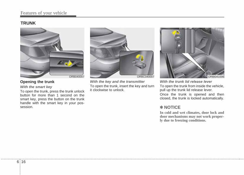
Opening the trunkWith the smart keyTo open the trunk, press the trunk unlockbutton for more than 1 second on thesmart key, press the button on the trunkhandle with the smart key in your pos-session.
With the key and the transmitterTo open the trunk, insert the key and turnit clockwise to unlock.
With the trunk lid release leverTo open the trunk from inside the vehicle,pull up the trunk lid release lever.Once the trunk is opened and thenclosed, the trunk is locked automatically.
✽✽ NOTICEIn cold and wet climates, door lock anddoor mechanisms may not work proper-ly due to freezing conditions.
TRUNK
ORBI041006ORB040007 ORBC040007
6 16
Features of your vehicle

Closing the trunkTo close, lower the trunk lid, then pressdown on it until it locks. To be sure thetrunk lid is securely fastened, alwayscheck by trying to pull it up again.
WARNINGThe trunk lid should be always keptcompletely closed while the vehicleis in motion. If it is left open or ajar,poisonous exhaust gases mayenter the car and serious illness ordeath may result.
WARNINGNo one should be allowed to occu-py the trunk at any time. The trunkis a very dangerous location in theevent of a crash.
CAUTIONMake certain that you close thetrunk before driving your vehicle.Possible damage may occur to thetrunk lift cylinders and attachedhardware if the trunk is not closedprior to driving.
WARNINGThe trunk swings upward. Makesure no objects or people are nearthe rear of the vehicle when open-ing the trunk.
Features of your vehicle
176

(1) Driver’s door power window switch(2) Front passenger’s door power win-
dow switch(3) Rear door (right) power window
switch*(4) Rear door (left) power window
switch*(5) Window opening and closing(6) Automatic power window down*
(Driver’s window)(7) Power window lock switch**: if equipped
✽✽ NOTICEIn cold and wet climates, power windowsmay not work properly due to freezingconditions.
WINDOWS
ORBI041008
6 18
Features of your vehicle

Power windows (if equipped)The ignition switch must be in the ONposition for power windows to operate.Each door has a power window switchthat controls the door's window. The driv-er has a power window lock switch whichcan block the operation of rear or front*windows. The power windows can beoperated for approximately 30 secondsafter the ignition key is removed orturned to the ACC or LOCK position.However, if the front doors open, thepower windows cannot be operated with-in the 30 second period after ignition keyremoval.* if equipped
✽✽ NOTICEWhile driving with the rear windowsdown or with the sunroof (if equipped)in an open (or partially open position),your vehicle may demonstrate a windbuffeting or pulsation noise. Thisnoise is a normal occurrence and can bereduced or eliminated by taking the fol-lowing actions. If the noise occurs withone or both of the rear windows down,partially lower both front windowsapproximately one inch. If you expe-rience the noise with the sunroof open,slightly reduce the size of the sunroofopening.
Window opening and closingThe driver’s door has a master powerwindow switch that controls all the win-dows in the vehicle. To open or close a window, press downor pull up the front portion of the corre-sponding switch to the first detent posi-tion (5).
Auto down window (if equipped) (Driver’s window)Pressing the power window switchmomentarily to the second detent posi-tion (6) completely lowers the driver’swindow even when the switch isreleased. To stop the window at thedesired position while the window is inoperation, pull up the switch momentari-ly to the opposite direction of the windowmovement.
ORBI041092 ORBI041093
Features of your vehicle
196

Power window lock button (if equipped) • The driver can disable the power win-
dow switches on the passenger doorsby depressing the power window lockswitch located on the driver’s door toLOCK (pressed).
• When the power window lockswitch is ON, the driver’s mastercontrol cannot operate the rear orfront* passenger door power win-dows.
* if equipped
CAUTION• To prevent possible damage to
the power window system, do notopen or close two windows ormore at the same time. This willalso ensure the longevity of thefuse.
• Never try to operate the mainswitch on the driver's door andthe individual door windowswitch in opposing directions atthe same time. If this is done, thewindow will stop and cannot beopened or closed.
ORBI041009
WARNING - Windows• NEVER leave the ignition key in
the vehicle. • NEVER leave any child unattend-
ed in the vehicle. Even veryyoung children may inadvertentlycause the vehicle to move, entan-gle themselves in the windows,or otherwise injure themselves orothers.
• Always double check to makesure all arms, hands, head andother obstructions are safely outof the way before closing a win-dow.
• Do not allow children to play withthe power windows. Keep the dri-ver’s door power window lockswitch in the LOCK position(depressed). Serious injury canresult from unintentional windowoperation by the child.
• Do not extend a face or arms out-side through the window openingwhile driving.
6 20
Features of your vehicle

Manual windows (if equipped)To raise or lower the window, turn thewindow regulator handle clockwise orcounterclockwise.
WARNINGWhen opening or closing the win-dows, make sure your passenger'sarms, hands and body are safelyout of the way.
OSA028222
Features of your vehicle
216

Opening the hood 1. Pull the release lever to unlatch the
hood. The hood should pop openslightly.
2. Go to the front of the vehicle, raise thehood slightly, pull the secondary latch(1) inside of the hood center and liftthe hood (2).
3. Pull the support rod from the hood.4. Hold the hood open with the support
rod.
HOOD
ORB040011 ORBC040012
WARNING - Hot partsGrasp the support rod in the areawrapped in rubber. The rubber willhelp prevent you from beingburned by hot metal when theengine is hot.
WARNINGOpen the hood after turning off theengine on a flat surface, shiftingthe shift lever to the P(Park) posi-tion for automatic transaxle and tothe 1st(First) gear or R(Reverse) formanual transaxle, and setting theparking brake.
6 22
Features of your vehicle
ORBI041010
■ Type A
■ Type B
ORBI041010

Closing the hood1.Before closing the hood, check the fol-
lowing:• All filler caps in engine compartment
must be correctly installed. • Gloves, rags or any other com-
bustible material must be removedfrom the engine compartment.
2.Return the support rod to its clip to pre-vent it from rattling.
3.Lower the hood until it is about 30 cmabove the closed position and let itdrop. Make sure that it locks into place.
WARNING - Hood• Before closing the hood, ensure
that all obstructions are removedfrom the hood opening. Closingthe hood with an obstructionpresent in the hood opening mayresult in property damage orsevere personal injury.
• Do not leave gloves, rags or anyother combustible material in theengine compartment. Doing somay cause a heat-induced fire.
WARNING • Always double check to be sure
that the hood is firmly latchedbefore driving away. If it is notlatched, the hood could fly openwhile the vehicle is being driven,causing a total loss of visibility,which might result in an accident.
• The support rod must be insertedcompletely into the hole providedin the hood whenever youinspect the engine compartment.This will prevent the hood fromfalling and possibly injuring you.
• Do not move the vehicle with thehood in the raised position, asvision is obstructed and the hoodcould fall or be damaged.
Features of your vehicle
236

Opening the fuel filler lidThe fuel-filler lid must be opened frominside the vehicle by pulling up on thefuel-filler lid opener located on the frontfloor area on the driver’s seat.
✽✽ NOTICEIf the fuel filler lid will not open becauseice has formed around it, tap lightly orpush on the lid to break the ice andrelease the lid. Do not pry on the lid. Ifnecessary, spray around the lid with anapproved de-icer fluid (do not use radi-ator anti-freeze) or move the vehicle to awarm place and allow the ice to melt.
1. Stop the engine.2. To open the fuel filler lid, pull up the
fuel filler lid opener.3. Pull the fuel filler lid (1) out to fully
open.4. To remove the cap, turn the fuel tank
cap (2) counterclockwise.5. Refuel as needed.
Closing the fuel filler lid1. To install the cap, turn it clockwise
until it “clicks”. This indicates that thecap is securely tightened.
2. Close the fuel filler lid and push it light-ly and make sure that it is securelyclosed.
FUEL FILLER LID
ORBI041013 ORB040014
WARNING - Refueling• If pressurized fuel sprays out, it
can cover your clothes or skinand thus subject you to the riskof fire and burns. Always removethe fuel cap carefully and slowly.If the cap is venting fuel or if youhear a hissing sound, wait untilthe condition stops before com-pletely removing the cap.
• Do not "top off" after the nozzleautomatically shuts off whenrefueling.
• Always check that the fuel cap isinstalled securely to prevent fuelspillage in the event of an acci-dent.
6 24
Features of your vehicle

(Continued)• Do not get back into a vehicle
once you have begun refuelingsince you can generate staticelectricity by touching, rubbingor sliding against any item or fab-ric (polyester, satin, nylon, etc.)capable of producing static elec-tricity. Static electricity dischargecan ignite fuel vapors resulting inrapid burning. If you must re-enter the vehicle, you shouldonce again eliminate potentiallydangerous static electricity dis-charge by touching a metal partof the vehicle, away from the fuelfiller neck, nozzle or other gaso-line source.
• When using an approvedportable fuel container, be sureto place the container on theground prior to refueling. Staticelectricity discharge from thecontainer can ignite fuel vaporscausing a fire. Once refueling hasbegun, contact with the vehicleshould be maintained until thefilling is complete.
(Continued)
WARNING - Refueling dan-gers
Automotive fuels are flammablematerials. When refueling, pleasenote the following guidelines care-fully. Failure to follow these guide-lines may result in severe personalinjury, severe burns or death by fireor explosion.• Read and follow all warnings at
the gas station facility.• Before refueling note the location
of the Emergency Gasoline Shut-Off, if available, at the gas stationfacility.
• Before touching the fuel nozzle,you should eliminate potentiallydangerous static electricity dis-charge by touching anothermetal part of the vehicle, a safedistance away from the fuel fillerneck, nozzle, or other gas source.
(Continued)
(Continued)Use only approved portable plas-tic fuel containers designed tocarry and store gasoline.
• Do not use cellular phones whilerefueling. Electric current and/orelectronic interference from cel-lular phones can potentiallyignite fuel vapors causing a fire.
• When refueling, always shut theengine off. Sparks produced byelectrical components related tothe engine can ignite fuel vaporscausing a fire. Once refueling iscomplete, check to make sure thefiller cap and filler door aresecurely closed, before startingthe engine.
• DO NOT use matches or a lighterand DO NOT SMOKE or leave a litcigarette in your vehicle while ata gas station especially duringrefueling. Automotive fuel ishighly flammable and can, whenignited, result in fire.
(Continued)
Features of your vehicle
256
(Continued)• If a fire breaks out during refuel-
ing, leave the vicinity of the vehi-cle, and immediately contact themanager of the gas station andthen contact the local fire depart-ment. Follow any safety instruc-tions they provide.
CAUTION• Make sure to refuel your vehicle
according to the "Fuel require-ments" suggested in section 3.
• If the fuel filler cap requiresreplacement, we recommend touse parts from an authorizedHYUNDAI dealer. An incorrectfuel filler cap can result in a seri-ous malfunction of the fuel sys-tem or emission control system.
• Do not spill fuel on the exteriorsurfaces of the vehicle. Any typeof fuel spilled on painted surfacesmay damage the paint.
• After refueling, make sure the fuelcap is installed securely to pre-vent fuel spillage in the event ofan accident.
6 26
Features of your vehicle
Electric power steering Power steering uses the motor to assistyou in steering the vehicle. If the engineis off or if the power steering systembecomes inoperative, the vehicle maystill be steered, but it will requireincreased steering effort.The motor driven power steering is con-trolled by power steering control unitwhich sense the steering wheel torque,steering wheel position and vehiclespeed to command the motor.The steering wheel becomes heavier asthe vehicle’s speed increases andbecomes lighter as the vehicle’s speeddecreases for the better control of thesteering wheel.Should you notice any change in theeffort required to steer during normalvehicle operation, have the power steer-ing checked. We recommend to have itchecked by an authorized HYUNDAIdealer.
✽✽ NOTICEThe following symptoms may occur dur-ing normal vehicle operation:• The EPS warning light does not illu-
minate.• The steering wheel becomes heavier
after turning the ignition switch on.This happens as the system performsthe EPS system diagnostics. When thediagnostics is completed, the steeringwheel will return to its normal condi-tion.
• Click noise may be heard from theEPS relay after the ignition switch isturned to the ON or LOCK position.
• Motor noise may be heard when thevehicle is at a stop or at a low drivingspeed.
• If the Electric Power Steering Systemdoes not operate normally, the warn-ing light will illuminate on the instru-ment cluster. The steering wheel maybecome difficult to control or operateabnormally. Have the vehicle checkedas soon as possible. We recommend tohave it checked by an authorizedHYUNDAI dealer.
• When you operate the steering wheelin low temperature, abnormal noisecould occur. If temperature rises, thenoise will disappear. This is a normalcondition.
Tilt steering Tilt steering allows you to adjust thesteering wheel before you drive. You canalso raise it to give your legs more roomwhen you exit and enter the vehicle.
The steering wheel should be positionedso that it is comfortable for you to drive,while permitting you to see the instru-ment panel warning lights and gauges.
STEERING WHEEL
WARNING• Never adjust the angle of the
steering wheel while driving. Youmay lose steering control andcause severe personal injury,death or accidents.
• After adjusting, push the steeringwheel both up and down to becertain it is locked in position.
Features of your vehicle
276
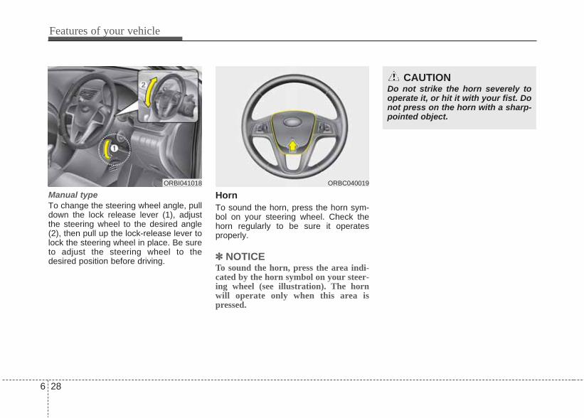
Manual typeTo change the steering wheel angle, pulldown the lock release lever (1), adjustthe steering wheel to the desired angle(2), then pull up the lock-release lever tolock the steering wheel in place. Be sureto adjust the steering wheel to thedesired position before driving.
HornTo sound the horn, press the horn sym-bol on your steering wheel. Check thehorn regularly to be sure it operatesproperly.
✽✽ NOTICETo sound the horn, press the area indi-cated by the horn symbol on your steer-ing wheel (see illustration). The hornwill operate only when this area ispressed.
ORBI041018
CAUTIONDo not strike the horn severely tooperate it, or hit it with your fist. Donot press on the horn with a sharp-pointed object.
ORBC040019
6 28
Features of your vehicle

Inside rearview mirrorAdjust the rearview mirror to center onthe view through the rear window. Makethis adjustment before you start driving.
Day/night rearview mirror Make this adjustment before you startdriving and while the day/night lever is inthe day position.Pull the day/night lever toward you toreduce the glare from the headlights ofthe vehicles behind you during night driv-ing.Remember that you lose some rearviewclarity in the night position.
Electric chromic mirror (ECM) (if equipped)The electric chromic mirror automaticallycontrols the glare from the headlights ofthe car behind you in nighttime or lowlight driving conditions. The sensormounted in the mirror senses the lightlevel around the vehicle, and automati-cally controls the headlight glare fromvehicles behind you.When the engine is running, the glare isautomatically controlled by the sensormounted in the rearview mirror.Whenever the shift lever is shifted into R(Reverse), the mirror will automaticallygo to the brightest setting in order toimprove the drivers view behind the vehi-cle.
MIRRORS
CAUTIONWhen cleaning the mirror, use apaper towel or similar materialdampened with glass cleaner. Donot spray glass cleaner directly onthe mirror as that may cause the liq-uid cleaner to enter the mirrorhousing.
WARNING - Rear visibilityDo not place objects in the rearseat or cargo area which wouldinterfere with your vision throughthe rear window.
ORB040020
WARNING Do not modify the inside mirror anddo not install a wide mirror. It couldresult in injury, during an accidentor deployment of the air bag.
Day
Night
Features of your vehicle
296
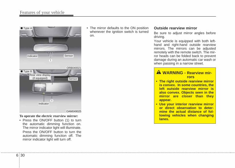
To operate the electric rearview mirror:• Press the ON/OFF button (1) to turn
the automatic dimming function on.The mirror indicator light will illuminate.Press the ON/OFF button to turn theautomatic dimming function off. Themirror indicator light will turn off.
• The mirror defaults to the ON positionwhenever the ignition switch is turnedon.
Outside rearview mirror Be sure to adjust mirror angles beforedriving.Your vehicle is equipped with both left-hand and right-hand outside rearviewmirrors. The mirrors can be adjustedremotely with the remote switch. The mir-ror heads can be folded back to preventdamage during an automatic car wash orwhen passing in a narrow street.
WARNING - Rearview mir-rors
• The right outside rearview mirroris convex. In some countries, theleft outside rearview mirror isalso convex. Objects seen in themirror are closer than theyappear.
• Use your interior rearview mirroror direct observation to deter-mine the actual distance of fol-lowing vehicles when changinglanes.
ORB040021
OAM049025
■ Type A
■ Type B
Indicator Sensor
Sensor
Indicator
Rear view display(if equipped)
6 30
Features of your vehicle

Remote controlThe electric remote control mirror switchallows you to adjust the position of theleft and right outside rearview mirrors. Toadjust the position of either mirror, movethe lever (1) to R or L to select the rightside mirror or the left side mirror, thenpress a corresponding point ( ) on themirror adjustment control to position theselected mirror up, down, left or right.After adjustment, put the lever into neu-tral position to prevent the inadvertentadjustment. The ignition switch must be in the ACC orON position for electric remote controlmirror to operate.
ORBI041023
CAUTIONDo not scrape ice off the mirrorface; this may damage the surfaceof the glass. If ice should restrictmovement of the mirror, do notforce the mirror for adjustment. Toremove ice, use a deicer spray, or asponge or soft cloth with very warmwater.
CAUTIONIf the mirror is jammed with ice, donot adjust the mirror by force. Usean approved spray de-icer (not radi-ator antifreeze) to release thefrozen mechanism or move thevehicle to a warm place and allowthe ice to melt.
WARNING Do not adjust or fold the outsiderearview mirrors while the vehicleis moving. This could result in lossof control, and an accident whichcould cause death, serious injuryor property damage.
Features of your vehicle
316
CAUTION• The mirrors stop moving when
they reach the maximum adjust-ing angles, but the motor contin-ues to operate while the switch isdepressed. Do not depress theswitch longer than necessary, themotor may be damaged.
• Do not attempt to adjust the out-side rearview mirror by hand.Doing so may damage the parts.

Folding the outside rearview mirrorManual typeTo fold outside rearview mirror, grasp thehousing of mirror and then fold it towardthe rear of the vehicle.
Electric Type (if equipped)To fold the outside rearview mirror,depress the button. To unfold it, depressthe button again.
ORB040024/H
CAUTION• The electric type outside rearview
mirror operates even though theignition switch is in the OFF posi-tion. However, to prevent unnec-essary battery discharge, do notadjust the mirrors longer thannecessary while the engine is notrunning.
• In case it is an electric type out-side rearview mirror, don’t fold itby hand. It could cause motor failure.
6 32
Features of your vehicle
ORBI041024
■ Type A ■ Type B

INSTRUMENT CLUSTER
1. Tachometer
2. Turn signal indicators
3. Speedometer
4. Engine temperature gauge
5. Fuel gauge
6. Warning and indicator lights
7. Odometer/Trip computer*
* : if equipped
* The actual cluster in the vehicle may differfrom the illustration.For more details refer to the "Gauges" inthe next pages.
ORBI041025/ORBI041026
■ Type A
■ Type B
Features of your vehicle
336
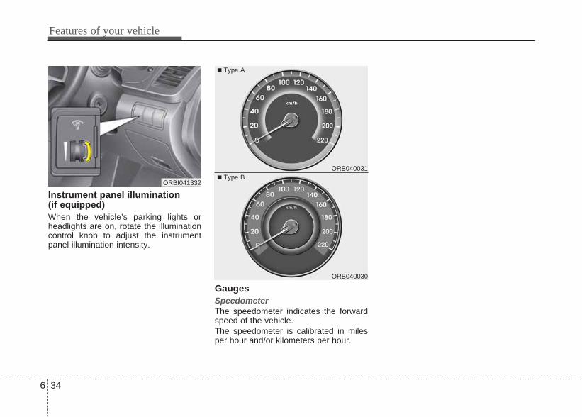
Instrument panel illumination (if equipped)When the vehicle’s parking lights orheadlights are on, rotate the illuminationcontrol knob to adjust the instrumentpanel illumination intensity.
GaugesSpeedometer The speedometer indicates the forwardspeed of the vehicle.The speedometer is calibrated in milesper hour and/or kilometers per hour.
ORBI041332
ORB040031
ORB040030
6 34
Features of your vehicle
■ Type A
■ Type B

ORB040304
DieselDiesel■ Type A
DieselDiesel■ Type B
ORB040307
ORB040305
GasolineGasoline■ Type A
GasolineGasoline■ Type B
ORB040306
Tachometer The tachometer indicates the approximate number of engine revolutions per minute(rpm).Use the tachometer to select the correct shift points and to prevent lugging and/orover-revving the engine.When the door is open, or if the engine is not started within 1 minute, the tachometerpointer may move slightly in ON position with the engine OFF. This movement is nor-mal and will not affect the accuracy of the tachometer once the engine is running.
CAUTIONDo not operate the engine withinthe tachometer's RED ZONE. Thismay cause severe engine damage.
Features of your vehicle
356

Engine temperature gaugeThis gauge shows the temperature of theengine coolant when the ignition switchis ON.Do not continue driving with an overheat-ed engine. If your vehicle overheats,refer to “If the engine overheats” in sec-tion 8.
Fuel gaugeThe fuel gauge indicates the approxi-mate amount of fuel remaining in the fueltank. The fuel tank capacity is given in section 10. The fuel gauge is supple-mented by a low fuel warning light, whichwill illuminate when the fuel tank is nearempty.On inclines or curves, the fuel gaugemay fluctuate or the low fuel warning lightmay come on earlier than usual due tothe movement of fuel in the tank.
CAUTIONIf the gauge pointer moves beyondthe normal range area toward the“H” position, it indicates overheat-ing that may damage the engine.
ORB040308
WARNINGNever remove the radiator capwhen the engine is hot. The enginecoolant is under pressure andcould cause severe burns. Waituntil the engine is cool beforeadding coolant to the reservoir.
■ Type A ■ Type B
ORB040034
■ Type A ■ Type B
6 36
Features of your vehicle
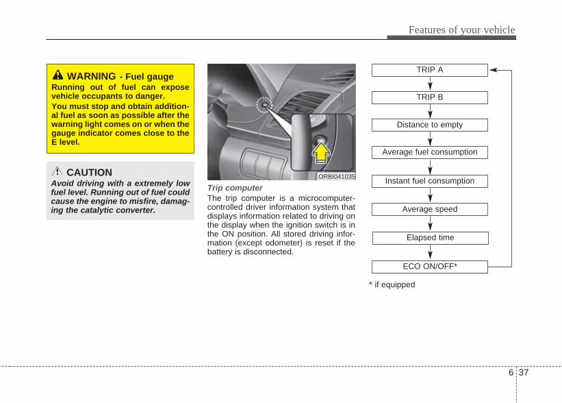
Trip computerThe trip computer is a microcomputer-controlled driver information system thatdisplays information related to driving onthe display when the ignition switch is inthe ON position. All stored driving infor-mation (except odometer) is reset if thebattery is disconnected.
WARNING - Fuel gaugeRunning out of fuel can exposevehicle occupants to danger.You must stop and obtain addition-al fuel as soon as possible after thewarning light comes on or when thegauge indicator comes close to theE level.
CAUTIONAvoid driving with a extremely lowfuel level. Running out of fuel couldcause the engine to misfire, damag-ing the catalytic converter.
ORBI041035
TRIP A
TRIP B
Average speed
Elapsed time
Distance to empty
Average fuel consumption
Instant fuel consumption
* if equipped
ECO ON/OFF*
Features of your vehicle
376
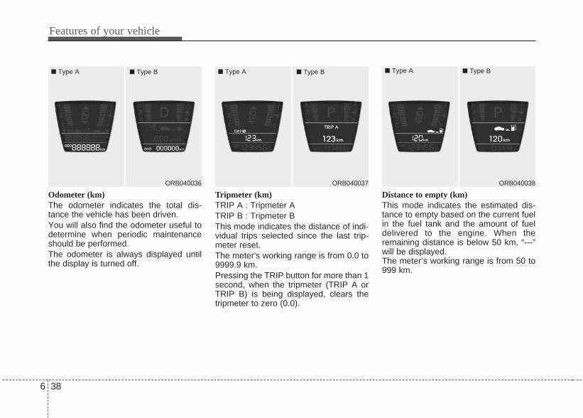
Odometer (km)The odometer indicates the total dis-tance the vehicle has been driven.You will also find the odometer useful todetermine when periodic maintenanceshould be performed.The odometer is always displayed untilthe display is turned off.
Tripmeter (km)TRIP A : Tripmeter ATRIP B : Tripmeter BThis mode indicates the distance of indi-vidual trips selected since the last trip-meter reset. The meter's working range is from 0.0 to9999.9 km.Pressing the TRIP button for more than 1second, when the tripmeter (TRIP A orTRIP B) is being displayed, clears thetripmeter to zero (0.0).
Distance to empty (km)This mode indicates the estimated dis-tance to empty based on the current fuelin the fuel tank and the amount of fueldelivered to the engine. When theremaining distance is below 50 km, “---”will be displayed.The meter’s working range is from 50 to999 km.
ORB040036 ORB040037 ORB040038
■ Type A ■ Type B ■ Type A ■ Type B■ Type A ■ Type B
6 38
Features of your vehicle

Average fuel consumption (if equipped)(Km/L)This mode calculates the average fuelconsumption from the total fuel used andthe distance since the last average con-sumption reset. The total fuel used is cal-culated from the fuel consumption input.For an accurate calculation, drive morethan 50 m.Pressing the TRIP button for more than 1second, when the average fuel consump-tion is being displayed, clears the aver-age fuel consumption to zero (--.-).If the vehicle speed exceeds 1 km/h afterrefueled more than 6 l, the average fuelconsumption will be cleared to zero (--.-).
Instant fuel consumption (Km/L)This mode calculates the instant fuelconsumption every 2 seconds from thedriving distance and quantity of fuelinjection.
Average speed (km/h)This mode calculates the average speedof the vehicle since the last averagespeed reset.Even if the vehicle is not in motion, theaverage speed keeps going while theengine is running.Pressing the TRIP button for more than 1second, when the average speed isbeing displayed, clears the averagespeed to zero (---). If you select the ECO OFF in the tripcomputer, the manual transaxle rightindicator will not illuminate.
ORB040039
■ Type A ■ Type B
Features of your vehicle
396
ORB040041
■ Type A ■ Type B
ORBI041040
■ Type B■ Type A

Elapsed timeThis mode indicates the total time trav-eled since the last driving time reset.Even if the vehicle is not in motion, thedriving time keeps going while the engineis running.The meter’s working range is from00:00~99:59.Pressing the TRIP button for more than 1second, when the driving time is beingdisplayed, clears the driving time to zero(00:00).
ECO ON/OFF mode (if equipped)You can turn the ECO indicator on/off onthe instrument cluster in this mode.If you push the TRIP button more than 1second in the ECO ON mode, ECO OFFis displayed in the screen and the ECOindicator turns off while driving.If you want to display the ECO indicatoragain, press the TRIP button more than1 second in the ECO OFF mode andthen ECO ON mode is displayed in thescreen.When you press the TRIP button lessthan 1 second in the ECO mode, themode is changed to tripmeter.If you select the ECO OFF in the tripcomputer, the manual transaxle rightindicator will not illuminate.
ORB040042 ORB040352
■ Type A ■ Type B ■ Type A
■ Type B
■ Type A
■ Type B
6 40
Features of your vehicle

✽✽ NOTICE• If the vehicle is not on level ground or
the battery power has been interrupt-ed, the “Distance to empty” functionmay not operate correctly.The trip computer may not registeradditional fuel if less than 6 liters (1.6gallons) of fuel are added to the vehi-cle.
• The fuel consumption (if equipped)and distance to empty values mayvary significantly based on drivingconditions, driving habits, and condi-tion of the vehicle.
• The distance to empty value is an esti-mate of the available driving distance.This value may differ from the actualdriving distance available.
Features of your vehicle
416

Warnings and indicatorsAll warning lights are checked by turningthe ignition switch ON (do not start theengine). Any light that does not illuminateshould be checked. We recommend tohave it checked by an authorizedHYUNDAI dealer.After starting the engine, check to makesure that all warning lights are off. If anyare still on, this indicates a situation thatneeds attention. When releasing theparking brake, the brake system warninglight should go off. The fuel warning lightwill stay on if the fuel level is low.
ECO indicator (if equipped)
The ECO indicator is a system thatinforms you to drive economically.It is displayed if you drive fuel efficientlyto help you improve fuel efficiency.• The ECO indicator (green) will turn on
when you are driving fuel efficiently inthe ECO ON mode.If you don't want the indicator dis-played, you can turn the ECO ONmode to OFF mode by pressing theTRIP button.As per ECO ON/OFF Mode operation,refer to the previous page.
• The fuel-efficiency can be changed bythe driver's driving habit and road con-dition.
• It doesn't work at the condition whichdoesn't meet economical driving suchas P (Park), N (Neutral), R (Reverse)or sports mode.
• While the instant fuel consumptionmode is displayed on the LCD screen,the ECO indicator turns off.
WARNINGDon't keep watching the indicatorwhile driving. It will distract youwhile driving and cause an acci-dent that results in severe personalinjury.
ECO
6 42
Features of your vehicle

Air bag warning light(if equipped)
This warning light will illuminate forapproximately 6 seconds each time youturn the ignition switch to the ON posi-tion.This light also comes on when the Supplemental Restraint System (SRS) isnot working properly. If the SRS air bagwarning light does not come on, orcontinuously remains on after operatingfor about 6 seconds when you turned theignition switch to the ON position or start-ed the engine, or if it comes on whiledriving, have the SRS inspected. We rec-ommend to have it checked by anauthorized HYUNDAI dealer.
Anti-lock brake system(ABS) warning light (if equipped)
This light illuminates if the ignition switchis turned ON and goes off in approxi-mately 3 seconds if the system is operat-ing normally. If the ABS warning light remains on,comes on while driving, or does notcome on when the ignition switch isturned to the ON position, this indicatesthat there may be a malfunction with theABS.If this occurs, have your vehicle checkedas soon as possible. We recommend tohave it checked by an authorizedHYUNDAI dealer. The normal brakingsystem will still be operational, but with-out the assistance of the anti-lock brakesystem.
Electronic brakeforce distribution(EBD) systemwarning lightIf two warning lights illuminate at thesame time while driving, your vehiclemay have a malfunction with the ABSand EBD system.In this case, your ABS and regular brakesystem may not work normally. Haveyour vehicle checked as soon as possi-ble. We recommend to have it checkedby an authorized HYUNDAI dealer.
✽✽ NOTICEIf the ABS warning light or EBD warn-ing light is on and stays on, thespeedometer or odometer/tripmetermay not work. In this case, have yourvehicle checked as soon as possible. Werecommend to have it checked by anauthorized HYUNDAI dealer.
WARNINGIf the both ABS and brake warninglights are on and stay on, your vehi-cle’s brake system will not worknormally during sudden braking. Inthis case, avoid high speed drivingand abrupt braking. Have yourvehicle checked as soon as possi-ble. We recommend to have itchecked by an authorizedHYUNDAI dealer.
Features of your vehicle
436

Seat belt warning andchime (if equipped)
Seat belt warning lightAs a reminder to the driver, the seat beltwarning light will blink or illuminate forapproximately 6 seconds each time youturn the ignition switch ON regardless ofbelt fastening.For details, refer to the seat belt on chap-ter 5.
Turn signal indicator
The blinking green arrows on the instru-ment panel show the direction indicatedby the turn signals. If the arrow comes onbut does not blink, blinks more rapidlythan normal, or does not illuminate at all,a malfunction in the turn signal system isindicated. Your dealer should be consult-ed for repairs.
High beam indicator
This indicator illuminates when the head-lights are on and in the high beam posi-tion or when the turn signal lever ispulled into the Flash-to-Pass position.
Tail light indicator
This indicator illuminates when the taillights are on.
Engine oil pressure warning light
This warning light indicates the engine oilpressure is low.If the warning light illuminates while driv-ing:1. Drive safely to the side of the road and
stop.2. With the engine off, check the engine
oil level. If the level is low, add oil asrequired.
If the warning light remains on afteradding oil or if oil is not available, haveyour vehicle checked as soon as possi-ble. We recommend to have it checkedby an authorized HYUNDAI dealer.
CAUTIONIf the engine is not stopped imme-diately after the engine oil pressurewarning light is illuminated, severedamage could result.
6 44
Features of your vehicle

Parking brake & brakefluid warning light
Parking brake warning This light is illuminated when the parkingbrake is applied with the ignition switch inthe START or ON position. The warninglight should go off when the parkingbrake is released while the engine is run-ning.
Low brake fluid level warningIf the warning light remains on, it mayindicate that the brake fluid level in thereservoir is low.If the warning light remains on:1. Drive carefully to the nearest safe
location and stop your vehicle.2. With the engine stopped, check the
brake fluid level immediately and addfluid as required. Then check all brakecomponents for fluid leaks.
3. Do not drive the vehicle if leaks arefound, the warning light remains on orthe brakes do not operate properly.Have the vehicle towed and the brakesystem inspected and necessaryrepairs done. We recommend that youhave it done by an authorized Hyundaidealer.
Your vehicle is equipped with dual-diag-onal braking systems. This means youstill have braking on two wheels even ifone of the dual systems should fail. Withonly one of the dual systems working,more than normal pedal travel andgreater pedal pressure are required tostop the car. Also, the car will not stop inas short a distance with only a portion ofthe brake system working. If the brakesfail while you are driving, shift to a lowergear for additional engine braking andstop the car as soon as it is safe to do so.
CAUTIONIf the oil pressure warning lightstays on while the engine is run-ning, serious engine damage mayresult. The oil pressure warninglight comes on whenever there isinsufficient oil pressure. In normaloperation, it should come on whenthe ignition switch is turned on,then go out when the engine isstarted. If the oil pressure warninglight stays on while the engine isrunning, there is a serious malfunc-tion. If this happens, stop the car assoon as it is safe to do so, turn offthe engine and check the oil level. Ifthe oil level is low, fill the engine oilto the proper level and start theengine again. If the light stays onwith the engine running, turn theengine off immediately. In anyinstance where the oil light stays onwhen the engine is running, we rec-ommend that the engine should bechecked by an authorized HYUNDAIdealer before the car is drivenagain.
Features of your vehicle
456
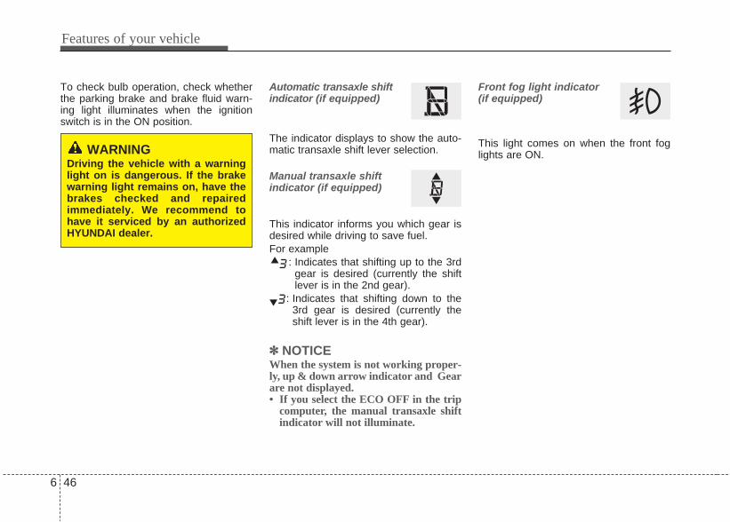
To check bulb operation, check whetherthe parking brake and brake fluid warn-ing light illuminates when the ignitionswitch is in the ON position.
Automatic transaxle shiftindicator (if equipped)
The indicator displays to show the auto-matic transaxle shift lever selection.
Manual transaxle shiftindicator (if equipped)
This indicator informs you which gear isdesired while driving to save fuel.For example
: Indicates that shifting up to the 3rdgear is desired (currently the shiftlever is in the 2nd gear).
: Indicates that shifting down to the3rd gear is desired (currently theshift lever is in the 4th gear).
✽✽ NOTICEWhen the system is not working proper-ly, up & down arrow indicator and Gearare not displayed.• If you select the ECO OFF in the trip
computer, the manual transaxle shiftindicator will not illuminate.
Front fog light indicator (if equipped)
This light comes on when the front foglights are ON.WARNING
Driving the vehicle with a warninglight on is dangerous. If the brakewarning light remains on, have thebrakes checked and repairedimmediately. We recommend tohave it serviced by an authorizedHYUNDAI dealer.
6 46
Features of your vehicle

Charging system warninglight
This warning light indicates a malfunctionof either the generator or electricalcharging system.If the warning light comes on while thevehicle is in motion:1. Drive to the nearest safe location.2. With the engine off, check the genera-
tor drive belt for looseness or break-age.
3. If the belt is adjusted properly, a prob-lem exists somewhere in the electricalcharging system. We recommend tohave the system checked by anauthorized HYUNDAI dealer.
Trunk lid/Tailgate openwarning light
This warning light illuminates when atrunk lid/tailgate is not closed securelywith the ignition in any position.
Door ajar warning light
This warning light illuminates when adoor is not closed securely with the igni-tion switch in any position.
Door open position indica-tor (if equipped)
This indicator illuminates when a door isnot closed securely. The indicator displays which door isopened.
Immobilizer indicator (if equipped)
Without smart key systemThis light illuminates when the immobiliz-er key is inserted and turned to the ONposition to start the engine.At this time, you can start the engine.The light goes out after the engine is run-ning. If this light blinks when the ignition switchis in the ON position before starting theengine, have the system checked. Werecommend to have it checked by anauthorized HYUNDAI dealer.
With smart key system (if equipped)If any of the following occurs in a vehicleequipped with the smart key, the immo-bilizer indicator illuminates, blinks or thelight goes off.• When the smart key is in the vehicle, if
the engine start/stop button is turned tothe ACC or ON position, the indicatorwill illuminate. However, when thesmart key is not in the vehicle, if theengine start/stop button is depressed,the indicator will blink for a few minutesto indicate that you will not be able tostart the engine.
Features of your vehicle
476

• When the ignition switch is turned tothe ON position and the indicator turnsoff after 2 seconds, the system mayhave a problem. We recommend tohave the vehicle checked by anauthorized HYUNDAI dealer.
• When the battery is weak, if the enginestart/stop button is depressed, the indi-cator will blink and you will not be ableto start the engine. However, you maystill be able to start the engine bypressing the engine start/stop buttonwith the smart key. If smart key systemrelated parts have a problem, the indi-cator blinks.
Low fuel level warning light
This warning light indicates the fuel tankis nearly empty. When it comes on, youshould add fuel as soon as possible.Driving with the fuel level warning light onor with the fuel level below “E” can causethe engine to misfire and damage thecatalytic converter.
Malfunction indicator light(MIL) (check engine light)
This indicator light is part of the EngineControl System which monitors variousemission control system components. Ifthis light illuminates while driving, it indi-cates that a potential malfunction hasbeen detected somewhere in the emis-sion control system.This light will also illuminate when theignition switch is turned to the ON posi-tion, and will go out in a few secondsafter the engine is started. If it illuminateswhile driving, or does not illuminate whenthe ignition switch is turned to the ONposition, have your vehicle checked. Werecommend that you have it checked byan authorized Hyundai dealer.Generally, your vehicle will continue tobe drivable, but have the systemchecked. We recommend to have itchecked by an authorized HYUNDAIdealer promptly.
6 48
Features of your vehicle
CAUTION - Diesel engine(if equipped with DPF)
When the malfunction indicatorlight is blinks, it may stop blinkingafter driving the vehicle at morethan 60km/h (37 mph) or at morethan second gear with 1500 ~ 2000engine rpm for a certain time (forabout 25 minutes).If the malfunction indicator lightcontinues to blink in spite of theprocedure, have the DPF systemchecked. We recommend to have itchecked by an authorized Hyundaidealer.If you continue to drive with themalfunction indicator light blinkingfor a long time, the DPF system canbe damaged and fuel consumptioncan be worsen.
CAUTIONProlonged driving with theEmission Control SystemMalfunction Indicator Light illumi-nated may cause damage to theemission control systems whichcould effect drivability and/or fueleconomy.
CAUTION - GasolineengineIf the Emission Control SystemMalfunction Indicator Light illumi-nates, potential catalytic converterdamage is possible which couldresult in loss of engine power. Havethe Engine Coolant systemchecked as soon as possible. Werecommend to have it checked byan authorized Hyundai dealer.
CAUTION - Diesel engineIf the Emission Control SystemMalfunction Indicator Light blinks,some error related to the injectionquantity adjustment occurs whichcould result in loss of enginepower, combustion noise and pooremission. Have the Engine Coolantsystem checked as soon as possi-ble. We recommend to have itchecked by an authorized Hyundaidealer.
Features of your vehicle
496

Engine coolant tempera-ture warning light (if equipped)
The warning light illuminates if the tem-perature of the engine coolant is above125±2.5°C (257±4.5°F). Do not continue driving with an overheat-ed engine. If your vehicle overheats,refer to “Overheating” in section 8.
✽✽ NOTICEIf the engine coolant temperature warn-ing light illuminates, it indicates over-heating that may damage the engine.
Glow indicator (Dieselengine)
The indicator light illuminates when theignition switch is placed at the ON posi-tion. The engine can be started after thepreheat indicator light goes off. The illu-minating time varies with the water tem-perature, air temperature and batterycondition.
✽ NOTICEIf the engine was not started within 10seconds after the preheating is complet-ed, turn the ignition key once more tothe LOCK position during 10 seconds,and then to the ON position, in order topreheat again.
Fuel filter warning light(Diesel engine)
This warning light illuminates for 3 sec-onds after the ignition switch is set to theON position and then it will go out. If itlights up while the engine is running, itindicates that water has accumulatedinside the fuel filter. If this happens,remove the water from the fuel filter. Formore Information, refer to “Fuel filter” insection 9.
CAUTIONWhen the fuel filter warning light isilluminated, engine power (vehiclespeed & idle speed) may decrease.If you keep driving with the warninglight on, you can damage your vehi-cle's engine parts and injection sys-tem of the Common Rail. If thisoccurs, have the vehicle checked.We recommend to have it checkedby an authorized Hyundai dealer.
CAUTIONIf the preheat indicator light contin-ues to illuminate or flash on and offafter the engine has warmed up orwhile driving, have the systemchecked. We recommend to have itchecked by an authorized Hyundaidealer.
6 50
Features of your vehicle

Electric power steering(EPS) system warning light
This indicator light comes on after theignition key is turned to the ON positionand then it will go out.This light also comes on when the EPShas some troubles. If it comes on whiledriving, have your vehicle inspected. Werecommend to have it inspected by anauthorized HYUNDAI dealer.
Warning on the LCD screen(if equipped)Key is not in vehicle
If the smart key isnot in the vehicleand if any door isopened or closedwith the ignitionswitch in ACC,ON, or START, the
warning illuminates on the LCD screen.The chime also sounds for 5 secondswhen there smart key is not in the vehi-cle and any door is closed.Turn the ignition switch off or get hold ofthe smart key.
Key is not detectedIf the smart key isnot in the vehicleor is not detectedand you push theengine start/stopbutton, the warn-ing illuminates onthe LCD screen for10 seconds.
EPS
Features of your vehicle
516
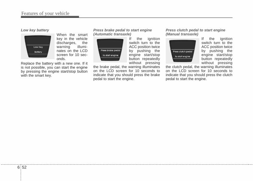
Low key batteryWhen the smartkey in the vehicledischarges, thewarning illumi-nates on the LCDscreen for 10 sec-onds.
Replace the battery with a new one. If itis not possible, you can start the engineby pressing the engine start/stop buttonwith the smart key.
Press brake pedal to start engine(Automatic transaxle)
If the ignitionswitch turn to theACC position twiceby pushing theengine start/stopbutton repeatedlywithout pressing
the brake pedal, the warning illuminateson the LCD screen for 10 seconds toindicate that you should press the brakepedal to start the engine.
Press clutch pedal to start engine(Manual transaxle)
If the ignitionswitch turn to theACC position twiceby pushing theengine start/stopbutton repeatedlywithout pressing
the clutch pedal, the warning illuminateson the LCD screen for 10 seconds toindicate that you should press the clutchpedal to start the engine.
6 52
Features of your vehicle

Shift to "P" positionIf you push theengine start/stopbutton with theignition switch ONand the shift levernot in P (Park), thewarning illumi-
nates on the LCD screen for 10 secondsto indicate that you should press thestart/stop button with the shift lever inP(Park) to turn off the engine.
Press start button with smart keyIf you push theengine start/ stopbutton while the"Key is not detect-ed" illuminates onthe LCD screen,the warning illumi-nates for 10 sec-onds.
Press start button againIf there is a prob-lem with theengine start/stopbutton system, thewarning illumi-nates for 10 sec-onds to indicate
that you could start the engine by press-ing the engine start/stop button whilepressing the brake pedal.If the warning illuminates each time youpush the start/stop button, take yourvehicle to an authorized HYUNDAI deal-er and have the system checked.
Features of your vehicle
536

Shift to "P" or "N" to start engineIf you try to startthe engine with theshift lever not in P(Park) or N(Neutral), thewarning illumi-nates for 10 sec-
onds on the LCD screen. You can also start the engine with theshift lever in N (Neutral), but for yoursafety start the engine with the shift leverin P (Park).
Press start button while turn steeringWhen the steeringwheel does notunlock, the warn-ing illuminates for10 seconds on theLCD screen.
Check steering wheel lockWhen the steeringwheel does notlock, the warningilluminates for 10seconds on theLCD screen.
6 54
Features of your vehicle

Steering wheel unlockedWhen the steeringwheel does notlock, the warningilluminates for 10seconds on theLCD screen.
Check stop lamp fuseWhen the stoplamp fuse is dis-connected, thewarning illumi-nates for 10 sec-onds on the LCDdisplay.
Replace the fuse with a new one. If thatis not possible you can start the engineby pressing the ENGINE START/STOPbutton for 10 seconds in ACC.
Features of your vehicle
556

The rear parking assist system assiststhe driver during backward movement ofthe vehicle by chiming if any object issensed within a distance of 120 cm (47in.) behind the vehicle. This system is asupplemental system and it is not intend-ed to nor does it replace the need forextreme care and attention of the driver.The sensing range and objectsdetectable by the back sensors are limit-ed. Whenever backing-up, pay as muchattention to what is behind you as youwould in a vehicle without a rear parkingassist system.
Operation of the rear parkingassist systemOperating condition• This system will activate when backing
up with the ignition switch ON.• The sensing distance while the rear
parking assist system is in operation isapproximately 120 cm (47 in.).
• When more than two objects aresensed at the same time, the closestone will be recognized first.
Types of warning sound• When an object is 120 cm to 81 cm (47
in. to 32 in.) from the rear bumper:Buzzer beeps intermittently.
• When an object is 80 cm to 41 cm (31in. to 16 in.) from the rear bumper:Buzzer beeps more frequently.
• When an object is within 40 cm (15 in.)of the rear bumper:Buzzer sounds continuously.
REAR PARKING ASSIST SYSTEM (IF EQUIPPED)
ORB040098
Sensors
WARNINGThe rear parking assist system is asupplementary function only. Theoperation of the rear parking assistsystem can be affected by severalfactors (including environmentalconditions). It is the responsibilityof the driver to always check thearea behind the vehicle before andwhile backing up.
6 56
Features of your vehicle

Type of the warning indicator (if equipped)
*1: It indicates the range of sensingobject by each sensor. (Left, Center,Right)
❈: In case of that the object is betweensensors or close, indicator could bedifferent.
Non-operational conditions ofrear parking assist systemThe rear parking assist system maynot operate properly when:1. Moisture is frozen to the sensor. (It will
operate normally when the moisturehas been cleared.)
2. The sensor is covered with foreignmatter, such as snow or water, or thesensor cover is blocked. (It will oper-ate normally when the material isremoved or the sensor is no longerblocked.)
3. Driving on uneven road surfaces(unpaved roads, gravel, bumps, gradi-ent).
4. Objects generating excessive noise(vehicle horns, loud motorcycleengines, or truck air brakes) are withinrange of the sensor.
5. Heavy rain or water spray exists.6. Wireless transmitters or mobile phones
are within range of the sensor.7. The sensor is covered with snow.
The detecting range may decreasewhen:1. The sensor is stained with foreign
matter such as snow or water. (Thesensing range will return to normalwhen removed.)
2. Outside air temperature is extremelyhot or cold.
The following objects may not be rec-ognized by the sensor:1. Sharp or slim objects such as ropes,
chains or small poles.2. Objects which tend to absorb the sen-
sor frequency such as clothes, spongymaterial or snow.
3. Undetectable objects smaller than 1 m(40 in.) in height and narrower than 14cm (6 in.) in diameter.
Distance fromobject
Warning indicator
Less than 40 cm (15 in.)
41cm ~80 cm (16 in. ~ 31 in.)
81cm ~ 120 cm (32 in. ~ 47 in.)
*1
*1
*1
Features of your vehicle
576

Rear parking assist system pre-cautions• The rear parking assist system may
not sound sequentially depending onthe speed and shapes of the objectsdetected.
• The rear parking assist system maymalfunction if the vehicle bumperheight or sensor installation has beenmodified or damaged. Any non-factoryinstalled equipment or accessoriesmay also interfere with the sensor per-formance.
• The sensor may not recognize objectsless than 40 cm (15 in.) from the sen-sor, or it may sense an incorrect dis-tance. Use caution.
• When the sensor is frozen or stainedwith snow, dirt, or water, the sensormay be inoperative until the stains areremoved using a soft cloth.
• Do not push, scratch or strike the sen-sor. Sensor damage could occur.
✽✽ NOTICEThis system can only sense objects with-in the range and location of the sensors;It can not detect objects in other areaswhere sensors are not installed. Also,small or slim objects, such as poles orobjects located between sensors may notbe detected by the sensors.Always visually check behind the vehi-cle when backing up.Be sure to inform any drivers of thevehicle that may be unfamiliar with thesystem regarding the systems capabili-ties and limitations.
Self-diagnosisIf you don’t hear an audible warningsound or if the buzzer sounds intermit-tently when shifting the gear to the R(Reverse) position, this may indicate amalfunction in the rear parking assist sys-tem. If this occurs, have your vehiclechecked. We recommend to have itchecked by an authorized Hyundai deal-er.
WARNINGPay close attention when the vehi-cle is driven close to objects on theroad, particularly pedestrians, andespecially children. Be aware thatsome objects may not be detectedby the sensors, due to the object’sdistance, size or material, all ofwhich can limit the effectiveness ofthe sensor. Always perform a visu-al inspection to make sure the vehi-cle is clear of all obstructionsbefore moving the vehicle in anydirection.
WARNINGYour new vehicle warranty doesnot cover any accidents or damageto the vehicle or injuries to its occu-pants due to a rear parking assistsystem malfunction. Always drivesafely and cautiously.
6 58
Features of your vehicle

The rearview camera will activate whenthe back-up light is ON with the ignitionswitch ON and the shift lever in the R(Reverse) position.This system is a supplemental systemthat shows behind the vehicle throughthe rearview display while backing-up.
The rearview camera may be turned offby pressing the ON/OFF button when therearview camera is activated. To turn the camera on again, press theON/OFF button again when the ignitionswitch is on and the shift lever in R(Reverse). Also, the camera will turn onautomatically whenever the ignitionswitch is turned off and on again.
✽✽ NOTICEThe rearview camera may not operatenormally, when you drive in theextremely high or low temperaturearea.(operating temperature: -20°C~65°C(-4°F ~ 149°F))
REARVIEW CAMERA (IF EQUIPPED)
WARNING• This system is a supplementary
function only. It is the responsi-bility of the driver to always checkthe inside/outside rearview mirrorand the area behind the vehiclebefore and while backing upbecause there is a dead zone thatcan't see through the camera.
• Always keep the camera lensclean. If lens is covered with for-eign matter, the camera may notoperate normally.
ORBI041359
ORB040330
Rear view display
ORBI041359M
Features of your vehicle
596
■ Type A
■ Type B
Rear view display

The hazard warning flasher should beused whenever you find it necessary tostop the car in a hazardous location.When you must make such an emer-gency stop, always pull off the road asfar as possible.The hazard warning lights are turned onby pushing in the hazard switch. Thiscauses all turn signal lights to blink. Thehazard warning lights will operate eventhough the key is not in the ignitionswitch.To turn the hazard warning lights off,push the switch a second time.
HAZARD WARNING FLASHER
ORB040045
6 60
Features of your vehicle

Battery saver function (if equipped) • The purpose of this feature is to pre-
vent the battery from being dis-charged. The system automaticallyturns off the parking lights when thedriver removes the ignition key (smartkey: turns off the engine) and opensthe driver-side door.
• With this feature, the parking lights willbe turned off automatically if the driverparks on the side of road at night.If necessary, to keep the lights onwhen the ignition key is removed,(smart key: turns off the engine) per-form the following:1) Open the driver-side door.2) Turn the parking lights OFF and ON
again using the light switch on thesteering column.
Lighting controlThe light switch has a Headlight and aParking light position.To operate the lights, turn the knob at theend of the control lever to one of the fol-lowing positions: (1) OFF position(2) Parking light position(3) Headlight position
Parking light position ( )When the light switch is in the parkinglight position, the tail, license and instru-ment panel lights are ON and the tail lightindicator is ON.
✽✽ NOTICEThe ignition switch must be in the ONposition to turn on the instrument panellights.
LIGHTING
CAUTIONIf the driver gets out of the vehiclethrough other doors (except dri-ver’s door), the battery saver func-tion does not operate. Therefore, itcauses the battery to be dis-charged. In this case, make sure toturn off the lamp before getting outof the vehicle.
ORBI041046 ORBI041047
Features of your vehicle
616

Headlight position ( )When the light switch is in the headlightposition the head, tail, position, licenseand instrument panel lights are ON.
✽✽ NOTICEThe ignition switch must be in the ONposition to turn on the headlights.
High beam operation To turn on the high beam headlights,push the lever away from you. Pull itback for low beams. The high beam indicator will light whenthe headlight high beams are switchedon. To prevent the battery from being dis-charged, do not leave the lights on for aprolonged time while the engine is notrunning.
WARNINGDo not use high beam when thereare other vehicles. Using highbeam could obstruct the other dri-ver's vision.
ORBI041048 ORBI041049
6 62
Features of your vehicle

Flashing headlights To flash the headlights, pull the levertowards you. It will return to the normal(low beam) position when released. Theheadlight switch does not need to be onto use this flashing feature.
Turn signals and lane changesignalsThe ignition switch must be on for theturn signals to function. To turn on theturn signals, move the lever up or down(A). Green arrow indicators on the instru-ment panel indicate which turn signal isoperating. They will self-cancel after aturn is completed. If the indicator continues to flash after aturn, manually return the lever to the OFFposition. To signal a lane change, move the turnsignal lever slightly and hold it in position(B). The lever will return to the OFF posi-tion when released.
If an indicator stays on and does notflash or if it flashes abnormally, one ofthe turn signal bulbs may be burned outand will require replacement.
✽✽ NOTICEIf an indicator flash is abnormally quickor slow, a bulb may be burned out orhave a poor electrical connection in thecircuit.
ORBI041050 ORBI041051
Features of your vehicle
636

Front fog light (if equipped) Fog lights are used to provide improvedvisibility and avoid accidents when visi-bility is poor due to fog, rain or snow etc.The fog lights will turn on when fog lightswitch (1) is turned to ON after the park-ing light is turned on.To turn off the fog lights, turn the switchto OFF.
✽✽ NOTICEThe ignition switch must be in the ONposition to turn on the front fog light.
Headlight leveling device To adjust the headlight beam levelaccording to the number of passengersand loading weight in the luggage area,turn the beam leveling switch.The higher the number of the switchposition, the lower the headlight beamlevel. Always keep the headlight beam atthe proper leveling position, or headlightsmay dazzle other road users.Listed below are the examples of properswitch settings. For loading conditionsother than those listed below, adjust theswitch position so that the beam levelmay be the nearest as the conditionobtained according to the list.
CAUTIONWhen in operation, the fog lightsconsume large amounts of vehicleelectrical power. Only use the foglights when visibility is poor orunnecessary battery and generatordrain could occur.
ORBI041052 ORBI041333
6 64
Features of your vehicle
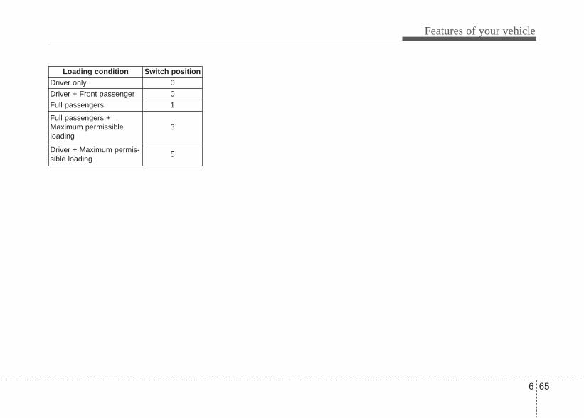
Loading condition Switch positionDriver only 0
Driver + Front passenger 0
Full passengers 1
Full passengers +Maximum permissibleloading
3
Driver + Maximum permis-sible loading
5
Features of your vehicle
656

A : Wiper speed control· MIST – Single wipe· OFF – Off· INT – Intermittent wipe · LO – Low wiper speed· HI – High wiper speed
B : Intermittent wipe time adjustment
C : Wash with brief wipes (front)
Windshield wipers Operates as follows when the ignitionswitch is turned ON.MIST : For a single wiping cycle, push
the lever upward and release itwith the lever in the OFF position.The wipers will operate continu-ously if the lever is pushedupward and held.
OFF : Wiper is not in operationINT : Wiper operates intermittently at the
same wiping intervals. Use thismode in a light rain or mist. To varythe speed setting, turn the speedcontrol knob.
LO : Normal wiper speedHI : Fast wiper speed
✽✽ NOTICEIf there is heavy accumulation of snowor ice on the windshield, defrost thewindshield for about 10 minutes, oruntil the snow and/or ice is removedbefore using the windshield wipers toensure proper operation.
Windshield washers In the OFF position, pull the lever gentlytoward you to spray washer fluid on thewindshield and to run the wipers 1-3cycles.Use this function when the windshield isdirty.The spray and wiper operation will con-tinue until you release the lever.If the washer does not work, check thewasher fluid level. If the fluid level is notsufficient, you will need to add appropri-ate non-abrasive windshield washer fluidto the washer reservoir.The reservoir filler neck is located in thefront of the engine compartment on thepassenger side.
WIPERS AND WASHERS
ORBI041054
Windshield wiper/washer
ORBI041056
6 66
Features of your vehicle

CAUTIONTo prevent possible damage to thewasher pump, do not operate thewasher when the fluid reservoir isempty.
WARNINGDo not use the washer in freezingtemperatures without first warmingthe windshield with the defrosters;the washer solution could freeze oncontact with the windshield andobscure your vision.
CAUTION• To prevent possible damage to
the wipers or windshield, do notoperate the wipers when thewindshield is dry.
• To prevent damage to the wiperblades, do not use gasoline,kerosene, paint thinner, or othersolvents on or near them.
• To prevent damage to the wiperarms and other components, donot attempt to move the wipersmanually.
Features of your vehicle
676

INTERIOR LIGHT
Automatic turn off function (if equipped)The interior lights automatically turn offapproximately 20 minutes after the igni-tion switch is turned off.
Map lamp • Push the lens to turn the map lamp on
or off. This light produces a spot beamfor convenient use as a map lamp atnight or as a personal lamp for the driv-er and the front passenger.
• ON : The map lamp stay on at alltimes.
• DOOR : In the DOOR position, themap lamp come on when anydoor is opened regardless ofthe ignition switch position.When doors are unlocked bythe transmitter (or smart key),the map lamp come on forapproximately 30 seconds aslong as any door is not open.
The map lamp goes out grad-ually after approximately 30seconds if the door is closed.However, if the ignition switchis ON or all doors are locked,the map lamp will turn offimmediately. If a door isopened with the ignition switchin the ACC or LOCK position,the map lamp stays on forabout 20 minutes. However, ifa door is opened with the igni-tion switch in the ON position,the map lamp stays on contin-uously.
• OFF : The lights turn off even if a dooris opened.❈ When the lamp is turned ON
by pressing the lens (1), thelamp does not turn off even ifthe switch (2) is in the OFFposition.
CAUTIONDo not use the interior lights forextended periods when the engineis not running.It may cause battery discharge.
ORBI041057
WARNINGDo not use the interior lights whendriving in the dark. Accidents couldhappen because the view may beobscured by interior lights.
6 68
Features of your vehicle

Room lamp• ON (1):In the ON position, the light stays on atall times.
• DOOR (2) :In the DOOR position, the light comes onwhen any door is opened regardless ofthe ignition switch position.When doors are unlocked by the trans-mitter (or smart key), the light comes onfor approximately 30 seconds as long asany door is not open. The light goes outgradually after approximately 30 sec-onds if the door is closed. However, if theignition switch is ON or all doors arelocked, the light will turn off immediately.If a door is opened with the ignitionswitch in the ACC or LOCK position, thelight stays on for about 20 minutes.However, if a door is opened with theignition switch in the ON position, thelight stays on continuously.
• OFF (3) :In the OFF position, the light stays off atall times even when a door is open.
Luggage room lampThe luggage room lamp comes on whenthe trunk lid/tailgate is opened.
ORB040361 ORBC040059
CAUTIONThe luggage room lamp comes onas long as the trunk lid/tailgateopens. To prevent unnecessarycharging system drain, close thetrunk lid/tailgate securely afterusing the luggage room.
Features of your vehicle
696

DEFROSTER
✽✽ NOTICEIf you want to defrost and defog thefront windshield, refer to “Windshielddefrosting and defogging” in this sec-tion. Rear window defroster
(if equipped)The defroster heats the window toremove frost, fog and thin ice from therear window, while the engine is running.To activate the rear window defroster,press the rear window defroster buttonlocated in the center facia switch panel. The indicator on the rear windowdefroster button illuminates when thedefroster is ON.If there is heavy accumulation of snow onthe rear window, brush it off before oper-ating the rear defroster.
The rear window defroster automaticallyturns off after approximately 20 minutesor when the ignition switch is turned off.To turn off the defroster, press the rearwindow defroster button again.
CAUTIONTo prevent damage to the conduc-tors bonded to the inside surface ofthe rear window, never use sharpinstruments or window cleanerscontaining abrasives to clean thewindow.
ORB040063R
6 70
Features of your vehicle
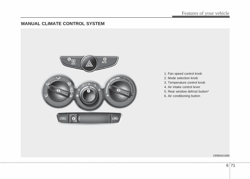
MANUAL CLIMATE CONTROL SYSTEM
1. Fan speed control knob2. Mode selection knob3. Temperature control knob4. Air intake control lever5. Rear window defrost button*6. Air conditioning button
ORBI041065
Features of your vehicle
716

Heating and air conditioning1. Start the engine.2. Set the mode to the desired position.
For improving the effectiveness ofheating and cooling;- Heating: - Cooling:
3. Set the temperature control to thedesired position.
4. Set the air intake control to the outside(fresh) air position.
5. Set the fan speed control to thedesired speed.
6. If air conditioning is desired, turn theair conditioning system on.
ORBI041066
6 72
Features of your vehicle

Mode selectionThe mode selection knob controls thedirection of the air flow through the venti-lation system. Air can be directed to the floor, dash-board outlets, or windshield. Five sym-bols are used to represent Five, Face, Bi-Level, Floor, Floor-Defrost and Defrostair position.
Face-Level (B, D)
Air flow is directed toward the upper bodyand face. Additionally, each outlet can becontrolled to direct the air dischargedfrom the outlet.
Bi-Level (B, D, C)
Air flow is directed towards the face andthe floor.
Floor-Level (C, A, D)
Most of the air flow is directed to thefloor, with a small amount of the air beingdirected to the windshield and side win-dow defrosters.
Floor/Defrost-Level (A, C, D)
Most of the air flow is directed to the floorand the windshield with a small amountdirected to the side window defrosters.
Defrost-Level (A, D)
Most of the air flow is directed to thewindshield with a small amount of airdirected to the side window defrosters.
ORBC040067
Features of your vehicle
736
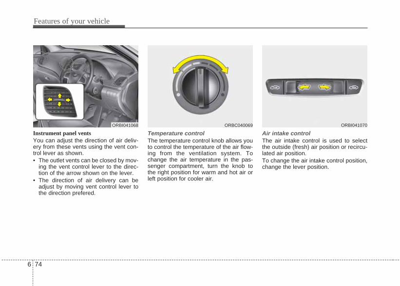
Instrument panel ventsYou can adjust the direction of air deliv-ery from these vents using the vent con-trol lever as shown.• The outlet vents can be closed by mov-
ing the vent control lever to the direc-tion of the arrow shown on the lever.
• The direction of air delivery can beadjust by moving vent control lever tothe direction prefered.
Temperature controlThe temperature control knob allows youto control the temperature of the air flow-ing from the ventilation system. Tochange the air temperature in the pas-senger compartment, turn the knob tothe right position for warm and hot air orleft position for cooler air.
Air intake control The air intake control is used to selectthe outside (fresh) air position or recircu-lated air position.To change the air intake control position,change the lever position.
ORBC040069ORBI041068 ORBI041070
6 74
Features of your vehicle

Recirculated air position With the recirculated airposition selected, air fromthe passenger compart-ment will be drawnthrough the heating sys-tem and heated or cooledaccording to the functionselected.
Outside (fresh) air position With the outside (fresh)air position selected, airenters the vehicle fromoutside and is heated orcooled according to thefunction selected.
✽✽ NOTICEProlonged operation of the heater in therecirculated air position (without airconditioning selected) may cause fog-ging of the windshield and side windowsand the air within the passenger com-partment may become stale.In addition, prolonged use of the airconditioning with the recirculated airposition selected will result in excessive-ly dry air in the passenger compart-ment.
WARNING• Continue using the climate con-
trol system in the recirculated airposition may allow humidity toincrease inside the vehicle whichmay fog the glass and obscurevisibility.
• Do not sleep in a vehicle with theair conditioning or heating sys-tem on. It may cause seriousharm or death due to a drop inthe oxygen level and/or bodytemperature.
• Continue using the climate con-trol system in the recirculated airposition can cause drowsinessor sleepiness, and loss of vehiclecontrol. Set the air intake controlto the outside (fresh) air positionas much as possible while driv-ing.
Features of your vehicle
756

Fan speed controlThe ignition switch must be in the ONposition for fan operation.The fan speed control knob allows you tocontrol the fan speed of the air flowingfrom the ventilation system. To changethe fan speed, turn the knob to the rightfor higher speed or left for lower speed.Setting the fan speed control knob to the“0” position turns off the fan.
Air conditioning Press the A/C button to turn the air con-ditioning system on (indicator light willilluminate). Press the button again to turnthe air conditioning system off.
System operationVentilation1. Set the mode to the position.2. Set the air intake control to the outside
(fresh) air position.3. Set the temperature control to the
desired position.4. Set the fan speed control to the
desired speed.
Heating1. Set the mode to the position.2. Set the air intake control to the outside
(fresh) air position.3. Set the temperature control to the
desired position.4. Set the fan speed control to the
desired speed.5. If dehumidified heating is desired, turn
the air conditioning system (ifequipped) on.
• If the windshield fogs up, set the modeto the or position.
ORBC040073 ORB040354R
6 76
Features of your vehicle

Operation Tips• To keep dust or unpleasant fumes
from entering the vehicle through theventilation system, temporarily set theair intake control to the recirculated airposition. Be sure to return the controlto the fresh air position when the irrita-tion has passed to keep fresh air in thevehicle. This will help keep the driveralert and comfortable.
• Air for the heating/cooling system isdrawn in through the grilles just aheadof the windshield. Care should betaken that these are not blocked byleaves, snow, ice or other obstructions.
• To prevent interior fog on the wind-shield, set the air intake control to thefresh air position and fan speed to thedesired position, turn on the air condi-tioning system, and adjust the temper-ature control to desired temperature.
Air conditioningAll HYUNDAI Air Conditioning Systemsare filled with environmentally friendly R-134a refrigerant which does not dam-age the ozone layer.1. Start the engine. Press the air condi-
tioning button.2. Set the mode to the position.3. Set the air intake control to the outside
air or recirculated air position.4. Adjust the fan speed control and tem-
perature control to maintain maximumcomfort.
• When maximum cooling is desired, setthe temperature control to the extremeleft position, set the mode control tothe position, set the fan speedcontrol to the highest speed, then setthe air intake control to the recirulatedair position.
✽✽ NOTICE• When using the air conditioning sys-
tem, monitor the temperature gaugeclosely while driving up hills or inheavy traffic when outside tempera-tures are high. Air conditioning sys-tem operation may cause engine over-heating. Continue to use the blowerfan but turn the air conditioning sys-tem off if the temperature gauge indi-cates engine overheating.
• When opening the windows in humidweather air conditioning may createwater droplets inside the vehicle.Since excessive water droplets maycause damage to electrical equipment,air conditioning should only be usedwith the windows closed.
Features of your vehicle
776
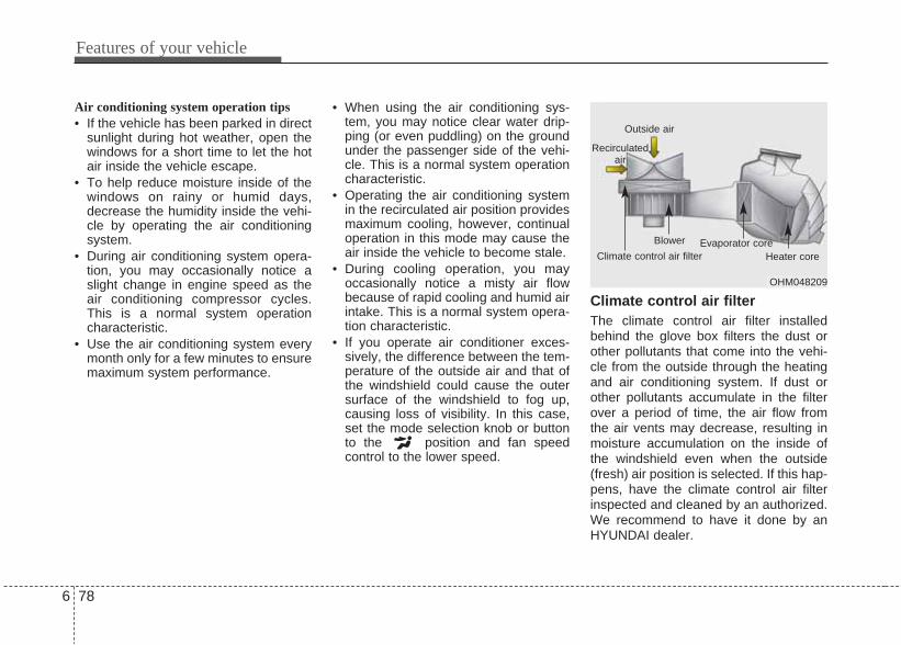
Air conditioning system operation tips • If the vehicle has been parked in direct
sunlight during hot weather, open thewindows for a short time to let the hotair inside the vehicle escape.
• To help reduce moisture inside of thewindows on rainy or humid days,decrease the humidity inside the vehi-cle by operating the air conditioningsystem.
• During air conditioning system opera-tion, you may occasionally notice aslight change in engine speed as theair conditioning compressor cycles.This is a normal system operationcharacteristic.
• Use the air conditioning system everymonth only for a few minutes to ensuremaximum system performance.
• When using the air conditioning sys-tem, you may notice clear water drip-ping (or even puddling) on the groundunder the passenger side of the vehi-cle. This is a normal system operationcharacteristic.
• Operating the air conditioning systemin the recirculated air position providesmaximum cooling, however, continualoperation in this mode may cause theair inside the vehicle to become stale.
• During cooling operation, you mayoccasionally notice a misty air flowbecause of rapid cooling and humid airintake. This is a normal system opera-tion characteristic.
• If you operate air conditioner exces-sively, the difference between the tem-perature of the outside air and that ofthe windshield could cause the outersurface of the windshield to fog up,causing loss of visibility. In this case,set the mode selection knob or buttonto the position and fan speedcontrol to the lower speed.
Climate control air filter The climate control air filter installedbehind the glove box filters the dust orother pollutants that come into the vehi-cle from the outside through the heatingand air conditioning system. If dust orother pollutants accumulate in the filterover a period of time, the air flow fromthe air vents may decrease, resulting inmoisture accumulation on the inside ofthe windshield even when the outside(fresh) air position is selected. If this hap-pens, have the climate control air filterinspected and cleaned by an authorized.We recommend to have it done by anHYUNDAI dealer.
OHM048209
Outside air
Recirculatedair
Climate control air filter
Blower Evaporator coreHeater core
6 78
Features of your vehicle

✽✽ NOTICE• Clean the filter according to the
Maintenance Schedule.If the vehicle is being driven in severeconditions such as dusty or roughroads, more frequent air conditionerfilter inspections and changes arerequired.
• When the air flow rate suddenlydecreases, the system should bechecked. We recommend to have itchecked at an authorized HYUNDAIdealer.
Checking the amount of air con-ditioner refrigerant and compres-sor lubricantWhen the amount of refrigerant is low,the performance of the air conditioning isreduced. Overfilling also has a negativeimpact on the air conditioning system.Therefore, if abnormal operation isfound, have the system inspected. Werecommend to have it inspected by anauthorized HYUNDAI dealer.
✽ NOTICEIt is important that the correct type andamount of oil and refrigerant is used.Otherwise, damage to the compressorand abnormal system operation mayoccur.
WARNINGWe recommend that the air condi-tioning system should be servicedby an authorized HYUNDAI dealer.Improper service may cause seri-ous injury to the person performingthe service.
Features of your vehicle
796

AUTOMATIC CLIMATE CONTROL SYSTEM (IF EQUIPPED)
1. AUTO (automatic control) button
2. OFF button
3. Temperature control knob
4. A/C display
5. Air intake control button
6. Fan speed control knob
7. Air conditioning button
8. Mode selection button
ORBI042340
6 80
Features of your vehicle

Automatic heating and air condi-tioningThe automatic climate control system iscontrolled by simply setting the desiredtemperature. The Full Automatic Temperature Control(FATC) system automatically controlsthe heating and cooling system as fol-lows;
1. Push the AUTO button. The modes,fan speeds, air intake and air-condi-tioning will be controlled automaticallyby temperature setting.
2. Turn the temperature control knob toset the desired temperature.If the temperature is set to the lowestsetting (LO), the air conditioning sys-tem will operate continuously.
3. To turn the automatic operation off,press any button except the tempera-ture control knob. If you press themode selection button, air conditioningbutton, defrost button, air intake con-trol button, or the fan speed knob, theselected function will be controlledmanually while other functions operateautomatically.
For your convenience and to improve theeffectiveness of the climate control, usethe AUTO button and set the tempera-ture to 23°C (73°F).
✽✽ NOTICENever place anything over the sensorlocated on the instrument panel toensure better control of the heating andcooling system.
ORB040353ORB040342
Features of your vehicle
816

Manual heating and air condition-ingThe heating and cooling system can becontrolled manually by pushing buttonsother than the AUTO button. In this case,the system works sequentially accordingto the order of buttons selected.When pressing any button except theAUTO button while using automaticoperation, the functions not selected willbe controlled automatically. 1. Start the engine.2. Set the mode to the desired position.
For improving the effectiveness ofheating and cooling;- Heating: - Cooling:
3. Set the temperature control to thedesired position.
4. Set the air intake control to the outside(fresh) air position.
5. Set the fan speed control to thedesired speed.
6. If air conditioning is desired, turn theair conditioning system on.
Press the AUTO button in order to con-vert to full automatic control of the sys-tem.
Mode selectionThe mode selection button controls thedirection of the air flow through the venti-lation system. The air flow outlet port is converted asfollows:
Refer to the illustration in the “Manual cli-mate control system”.
Floor & Defrost
Most of the air flow is directed to the floorand the windshield with a small amountdirected to the side window defrosters.
Face-Level
Air flow is directed toward the upper bodyand face. Additionally, each outlet can becontrolled to direct the air dischargedfrom the outlet.
Bi-Level
Air flow is directed towards the face andthe floor.
Floor-Level
Most of the air flow is directed to thefloor, with a small amount of the air beingdirected to the windshield and side win-dow defrosters.
ORB040347
6 82
Features of your vehicle

Defrost-LevelMost of the air flow is directed to thewindshield with a small amount of airdirected to the side window defrosters.
Instrument panel ventsYou can adjust the direction of air deliv-ery from these vents using the vent con-trol lever as shown.• The outlet vents can be closed by mov-
ing the vent control lever to the direc-tion of the arrow shown on the lever.
• The direction of air delivery can beadjust by moving vent control lever tothe direction prefered.
Temperature controlThe temperature will increase to themaximum by turning the knob to the rightextremely. The temperature will decrease to theminimum by turning the knob to the leftextremely. When turning the knob, the temperaturewill increase or decrease by 0.5°C (1°F).When set to the lowest temperature set-ting, the air conditioning will operate con-tinuously.
ORB040355R ORBI041068 ORB040341
Features of your vehicle
836
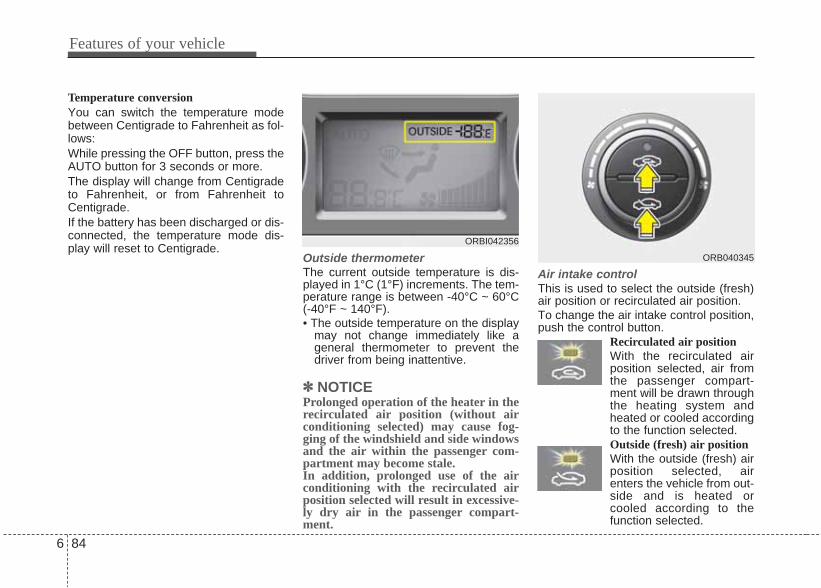
Temperature conversionYou can switch the temperature modebetween Centigrade to Fahrenheit as fol-lows:While pressing the OFF button, press theAUTO button for 3 seconds or more. The display will change from Centigradeto Fahrenheit, or from Fahrenheit toCentigrade.If the battery has been discharged or dis-connected, the temperature mode dis-play will reset to Centigrade.
Outside thermometerThe current outside temperature is dis-played in 1°C (1°F) increments. The tem-perature range is between -40°C ~ 60°C(-40°F ~ 140°F).• The outside temperature on the display
may not change immediately like ageneral thermometer to prevent thedriver from being inattentive.
✽✽ NOTICEProlonged operation of the heater in therecirculated air position (without airconditioning selected) may cause fog-ging of the windshield and side windowsand the air within the passenger com-partment may become stale.In addition, prolonged use of the airconditioning with the recirculated airposition selected will result in excessive-ly dry air in the passenger compart-ment.
Air intake controlThis is used to select the outside (fresh)air position or recirculated air position.To change the air intake control position,push the control button.
Recirculated air positionWith the recirculated airposition selected, air fromthe passenger compart-ment will be drawn throughthe heating system andheated or cooled accordingto the function selected.Outside (fresh) air positionWith the outside (fresh) airposition selected, airenters the vehicle from out-side and is heated orcooled according to thefunction selected.
ORB040345
ORBI042356
6 84
Features of your vehicle

Fan speed controlThe fan speed can be set to the desiredspeed by turning the fan speed controlknob. The higher the fan speed is, the more airis delivered.Pressing the OFF button turns off thefan.
Air conditioningPush the A/C button to turn the air condi-tioning system on (indicator light will illu-minate). Push the button again to turn the air con-ditioning system off.
WARNING• Continued climate control sys-
tem operation in the recirculatedair position may allow humidityto increase inside the vehiclewhich may fog the glass andobscure visibility.
• Do not sleep in a vehicle with theair conditioning or heating sys-tem on. It may cause seriousharm or death due to a drop inthe oxygen level and/or bodytemperature.
• Continued climate control sys-tem operation in the recirculatedair position can cause drowsi-ness or sleepiness, and loss ofvehicle control. Set the air intakecontrol to the outside (fresh) airposition as much as possiblewhile driving.
ORB040344 ORB040346
Features of your vehicle
856

OFF modePush the OFF button to turn off the air cli-mate control system. However, you canstill operate the mode and air intake but-tons as long as the ignition switch is inthe ON position.
ORB040343
6 86
Features of your vehicle

• For maximum defrosting, set the tem-perature control to the extremeright/hot position and the fan speedcontrol to the highest speed.
• If warm air to the floor is desired whiledefrosting or defogging, set the modeto the floor-defrost position.
• Before driving, clear all snow and icefrom the windshield, rear window, out-side rear view mirrors, and all side win-dows.
• Clear all snow and ice from the hoodand air inlet in the cowl grill to improveheater and defroster efficiency and toreduce the probability of fogging up theinside of the windshield.
Manual climate control systemTo defog inside windshield 1. Set the fan speed to the desired posi-
tion.2. Select desired temperature.3. Select the or position.4. Push the air conditioning button. Set
the air intake control to the outside(fresh) air position.
WINDSHIELD DEFROSTING AND DEFOGGING
WARNING - Windshieldheating
Do not use the or positionduring cooling operation inextremely humid weather. The dif-ference between the temperature ofthe outside air and that of the wind-shield could cause the outer sur-face of the windshield to fog up,causing loss of visibility. In thiscase, set the mode selection knobor button to the position andfan speed control knob or button tothe lower speed.
ORBI041075
Features of your vehicle
876

To defrost outside windshield 1. Set the fan speed to the highest posi-
tion.2. Set the temperature to the extreme
hot position.3. Select the position.4. Push the air conditioning button. Set
the air intake control to the outside(fresh) air position.
Automatic climate control systemTo defog inside windshield 1. Set the fan speed to the desired posi-
tion.2. Select desired temperature.3. Press the defrost button ( ).4. The air conditioning will be turned on
according to the detected ambienttemperature and outside (fresh) airposition will be selected automatically.
If the air conditioning and outside (fresh)air position are not selected automatical-ly, adjust the corresponding button man-ually. If the position is selected,lower fan speed is adjusted to a higherfan speed.
To defrost outside windshield 1. Set the fan speed to the highest
(extreme right) position.2. Set the temperature to the extreme
hot (HI) position.3. Press the defrost button ( ).4. The air conditioning will be turned on
according to the detected ambienttemperature and outside (fresh) airposition will be selected automatically.
If the position is selected, lower fanspeed is adjusted to a higher fan speed.
ORBI041348 ORBI041349ORBI041076
6 88
Features of your vehicle

Defogging logicTo reduce the probability of fogging upthe inside of the windshield, the air intakeor air conditioning are controlled auto-matically according to certain conditionssuch as or position. To cancelor return the defogging logic, do the fol-lowing.
Automatic climate control system1. Turn the ignition switch to the ON
position.2. Press the defrost button ( ).3. While holding the air conditioning
(A/C) button pressed, press the airintake control button (recirculated airposition) at least 5 times within 3 sec-onds.
The A/C display blinks 3 times with 0.5second of interval. It indicates that thedefogging logic is canceled or returned tothe programmed status.
If the battery has been discharged or dis-connected, it resets to the defog logicstatus.
ORBI041350
Features of your vehicle
896

These compartments can be used tostore small items required by the driveror passengers.
Center console storage (if equipped)To open the center console storage pullup the lever.
Sliding armrestTo move forwardGrab the front portion of the armrest (1)then pull it forward.
To move rearwardPush the armrest rearward with yourpalm.
STORAGE COMPARTMENTS
WARNING - Flammablematerials
Do not store cigarette lighters,propane cylinders, or other flam-mable/explosive materials in thevehicle. These items may catch fireand/or explode if the vehicle isexposed to hot temperatures forextended periods.
CAUTION• To avoid possible theft, do not
leave valuables in the storagecompartments.
• Always keep the storage com-partment covers closed whiledriving. Do not attempt to placeso many items in the storagecompartment that the storagecompartment cover cannot closesecurely.
ORB040351/H
CAUTIONDo not grap the front portion of thearmrest (1) when moving the arm-rest rearward. Your finger may becaught in the armrest.
ORBI041362
6 90
Features of your vehicle

Glove boxTo open the glove box, push the buttonand the glove box will automaticallyopen. Close the glove box after use.
Sunglass holder To open the sunglass holder, press thecover and the holder will slowly open.Place your sunglasses in the compart-ment door with the lenses facing out.Push to close.
ORB040081
WARNING• Do not keep objects except sun-
glasses inside the sunglass hold-er. Such objects can be thrownfrom the holder in the event of asudden stop or an accident, pos-sibly injuring the passengers inthe vehicle.
• Do not open the sunglass holderwhile the vehicle is moving. Therear view mirror of the vehiclecan be blocked by an open sun-glass holder.
ORBI041080
WARNING To reduce the risk of injury in anaccident or sudden stop, alwayskeep the glove box door closedwhile driving.
CAUTIONDo not keep food in the glove boxfor a long time.
Features of your vehicle
916

INTERIOR FEATURES Cup holder
Cups or small beverage cans may beplaced in the cup holders.
SunvisorUse the sunvisor to shield direct lightthrough the front or side windows.To use a sunvisor, pull it downward.To use a sunvisor for a side window, pullit downward, unsnap it from the bracket(1) and swing it to the side (2).To use the vanity mirror, pull down thesunvisor and slide the mirror cover (3).The ticket holder (4) is provided to holdtickets such as tollgate ticket.
WARNING - Hot liquids• Do not place uncovered cups of
hot liquid in the cup holder whilethe vehicle is in motion. If the hotliquid spills, you could beburned. Such a burn to the drivercould lead to loss of control ofthe vehicle.
• To reduce the risk of personalinjury in the event of sudden stopor collision, do not place uncov-ered or unsecured bottles, glass-es, cans, etc., in the cup holderwhile the vehicle is in motion.
ORBI041085ORB040078/H
WARNINGKeep cans or bottles out of directsun light and do not put them in avehicle that is heated up. It mayexplode.
WARNINGFor your safety, do not obstructyour vision when using the sunvi-sor.
6 92
Features of your vehicle

Power outletThe power outlet is designed to providepower for mobile telephones or otherdevices designed to operate with vehicleelectrical systems. The devices shoulddraw less than 10 amps with the enginerunning.
CAUTION• Use the power outlet only when
the engine is running and removethe accessory plug after use.Using the accessory plug for pro-longed periods of time with theengine off could cause the bat-tery to discharge.
• Only use 12V electric accessorieswhich are less than 10A in elec-tric capacity.
• Adjust the air-conditioner orheater to the lowest operatinglevel when using the power outlet.
• Close the cover when not in use.• Some electronic devices can
cause electronic interferencewhen plugged into a vehicle’spower outlet. These devices maycause excessive audio static andmalfunctions in other electronicsystems or devices used in yourvehicle.
WARNINGDo not put a finger or a foreign ele-ment (pin, etc.) into a power outletand do not touch with a wet hand.You may get an electric shock.
ORBI041084MT
Features of your vehicle
936
■ Type A
■ Type BORBI041084

Digital clock (if equipped)
Whenever the battery terminals or relat-ed fuses are disconnected, you mustreset the time.When the ignition switch is in the ACC orON position, the clock buttons operate asfollows:
Setup the clockWith audio off1. Press the [SETUP] button until the
clock of the display blinks. 2. Set the clock by turning the knob(1)
and press it.
With audio on1. Press the [SETUP] button.2. Select the [CLOCK] mode by turning
the knob(1) and press it.3. Set the clock by turning the knob(1)
and press it. Clothes hanger (if equipped)You can use the hanger to hang yourclothes.
ORB040086
WARNINGDo not adjust the clock while driv-ing. You may lose your steeringcontrol and cause severe personalinjury or accidents.
ORBI041363
CAUTIONDo not hang heavy clothes, sincethose may damage the hook.
6 94
Features of your vehicle

Floor mat anchor(s) (if equipped)When using a floor mat on the front floorcarpet, make sure it attaches to the floormat anchor(s) in your vehicle. This keepsthe floor mat from sliding forward.
OEL049222
■ Type A ■ Type B
WARNINGThe following must be observedwhen installing ANY floor mat tothe vehicle.• Ensure that the floor mats are
securely attached to the vehicle’sfloor mat anchor(s) before driv-ing the vehicle.
• Do not use ANY floor mat thatcannot be firmly attached to thevehicle’s floor mat anchors.
• Do not stack floor mats on top ofone another (e.g. all-weather rub-ber mat on top of a carpeted floormat). Only a single floor matshould be installed in each posi-tion.
IMPORTANT – Your vehicle wasmanufactured with driver’s sidefloor mat anchors that are designedto securely hold the floor mat inplace. To avoid any interferencewith pedal operation, HYUNDAI rec-ommends that only the HYUNDAIfloor mat designed for use in yourvehicle be installed.
Features of your vehicle
956
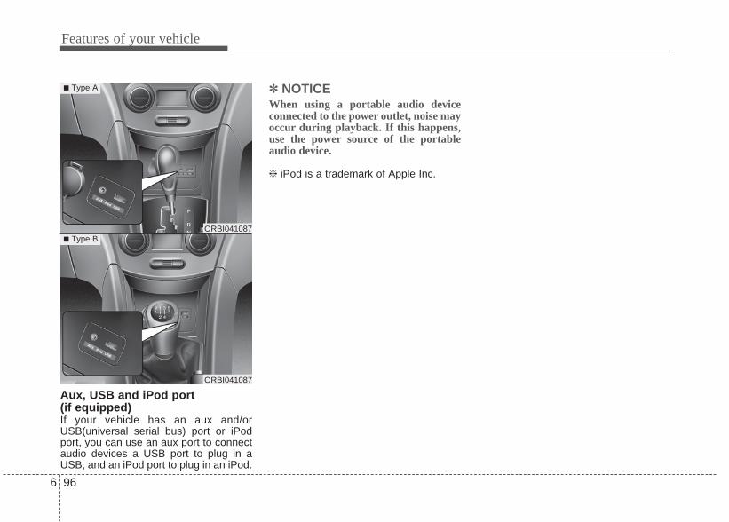
Features of your vehicle
966
Aux, USB and iPod port(if equipped)If your vehicle has an aux and/orUSB(universal serial bus) port or iPodport, you can use an aux port to connectaudio devices a USB port to plug in aUSB, and an iPod port to plug in an iPod.
✽ NOTICEWhen using a portable audio deviceconnected to the power outlet, noise mayoccur during playback. If this happens,use the power source of the portableaudio device.
❈ iPod is a trademark of Apple Inc.
ORBI041087
■ Type A
■ Type BORBI041087

6 97
Features of your vehicle
✽ NOTICEIf you install an aftermarket HID headlamp, your vehicle’s audio and electron-ic device may malfunction.
AntennaRoof antenna Your car uses a roof antenna to receiveboth AM and FM broadcast signals. Thisantenna is a removable type. To removethe antenna, turn it counterclockwise. Toinstall the antenna, turn it clockwise.
AUDIO SYSTEM
CAUTION• Before entering a place with a low
height clearance or a car wash,remove surely the antenna byrotating it counter-clockwise. Ifnot, the antenna may be dam-aged.
• When reinstalling your antenna, itis important that it is fully tight-ened and adjusted to the uprightposition to ensure proper recep-tion. But it could be folded orremoved when parking the vehi-cle or when loading cargo on theroof rack.
• When cargo is loaded on the roofrack, do not place the cargo nearthe antenna pole to ensure prop-er reception.
ORBC040088
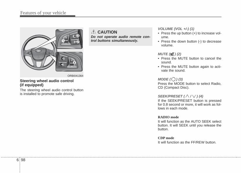
Features of your vehicle
986
Steering wheel audio control (if equipped)The steering wheel audio control buttonis installed to promote safe driving.
VOLUME (VOL +/-) (1)• Press the up button (+) to increase vol-
ume.• Press the down button (-) to decrease
volume.
MUTE ( ) (2)• Press the MUTE button to cancel the
sound.• Press the MUTE button again to acti-
vate the sound.
MODE ( ) (3)Press the MODE button to select Radio,CD (Compact Disc).
SEEK/PRESET ( / ) (4)If the SEEK/PRESET button is pressedfor 0.8 second or more, it will work as fol-lows in each mode.
RADIO modeIt will function as the AUTO SEEK selectbutton. It will SEEK until you release thebutton.
CDP modeIt will function as the FF/REW button.
CAUTIONDo not operate audio remote con-trol buttons simultaneously.
ORBI041364

6 99
Features of your vehicle
CDC modeIt will function as the DISC UP/DOWNbutton.
If the SEEK/PRESET button is pressedfor less than 0.8 second, it will work asfollows in each mode.
RADIO modeIt will function as the PRESET STATIONselect buttons.
CDP modeIt will function as the TRACK UP/DOWNbutton.
CDC modeIt will function as the TRACK UP/DOWNbutton.
Detailed information for audio controlbuttons is included in the following pagesin this section.
How car audio worksAM (MW, LW) and FM radio signals arebroadcast from transmitter towers locat-ed around your city. They are intercept-ed by the radio antenna on your car. Thissignal is then received by the radio andsent to your car speakers. When a strong radio signal has reachedyour vehicle, the precise engineering ofyour audio system ensures the best pos-sible quality reproduction. However, insome cases the signal coming to yourvehicle may not be strong and clear. Thiscan be due to factors such as the dis-tance from the radio station, closeness ofother strong radio stations or the pres-ence of buildings, bridges or other largeobstructions in the area.
AM (MW, LW) broadcasts can bereceived at greater distances than FMbroadcasts. This is because AM(MW,LW) radio waves are transmitted at lowfrequencies. These long, low frequencyradio waves can follow the curvature ofthe earth rather than travelling straightout into the atmosphere. In addition, theycurve around obstructions so that theycan provide better signal coverage.
JBM002
AM(MW, LW) reception
JBM001
FM reception

Features of your vehicle
1006
FM broadcasts are transmitted at highfrequencies and do not bend to follow theearth's surface. Because of this, FMbroadcasts generally begin to fade atshort distances from the station. Also,FM signals are easily affected by build-ings, mountains, or other obstructions.These can result in certain listening con-ditions which might lead you to believe aproblem exists with your radio. The fol-lowing conditions are normal and do notindicate radio trouble:
• Fading - As your car moves away fromthe radio station, the signal will weak-en and sound will begin to fade. Whenthis occurs, we suggest that you selectanother stronger station.
• Flutter/Static - Weak FM signals orlarge obstructions between the trans-mitter and your radio can disturb thesignal causing static or fluttering nois-es to occur. Reducing the treble levelmay lessen this effect until the distur-bance clears.
• Station Swapping - As a FM signalweakens, another more powerful sig-nal near the same frequency maybegin to play. This is because yourradio is designed to lock onto the clear-est signal. If this occurs, select anoth-er station with a stronger signal.
• Multi-Path Cancellation - Radio signalsbeing received from several directionscan cause distortion or fluttering. Thiscan be caused by a direct and reflect-ed signal from the same station, or bysignals from two stations with closefrequencies. If this occurs, selectanother station until the condition haspassed.
JBM005JBM004JBM003
FM radio station

6 101
Features of your vehicle
Using a cellular phone or a two-wayradio When a cellular phone is used inside thevehicle, noise may be produced from theaudio equipment. This does not meanthat something is wrong with the audioequipment. In such a case, use the cellu-lar phone at a place as far as possiblefrom the audio equipment.
Care of discs• If the temperature inside the car is too
high, open the car windows for ventila-tion before using your car audio.
• It is illegal to copy and use MP3/WMAfiles without permission. Use CDs thatare created only by lawful means.
• Do not apply volatile agents such asbenzene and thinner, normal cleanersand magnetic sprays made for ana-logue disc onto CDs.
• To prevent the disc surface from get-ting damaged. Hold and carry CDs bythe edges or the edges of the centerhole only.
• Clean the disc surface with a piece ofsoft cloth before playback (wipe it fromthe center to the outside edge).
• Do not damage the disc surface orattach pieces of sticky tape or paperonto it.
• Make sure nothing other than CDs areinserted into the CD player (Do notinsert more than one CD at a time).
• Keep CDs in their cases after use toprotect them from scratches or dirt.
• Depending on the type of CD-R/CD-RW CDs, certain CDs may not operatenormally depending upon manufactur-ing companies or processes andrecording methods. In such circum-stances, if you still continue to usethose CDs, they may cause the mal-function of your car audio system.
✽ NOTICE - Playing anIncompatible CopyProtected Audio CD
Some copy protected CDs, which do notcomply with the international audio CDstandards (Red Book), may not play onyour car audio. Please note that if youtry to play copy protected CDs and theCD player does not perform correctlythe CDs maybe defective, not the CDplayer.
CAUTIONWhen using a communication sys-tem such a cellular phone or a radioset inside the vehicle, a separateexternal antenna must be fitted.When a cellular phone or a radio setis used with an internal antennaalone, it may interfere with the vehi-cle's electrical system and adverse-ly affect safe operation of the vehi-cle.
WARNINGDon't use a cellular phone whenyou are driving. You should stop ata safe place to use a cellular phone.

Features of your vehicle
1026
RB_PA710RBI_RADI
■ CD Player : PA710RBI
❋There will be no logo if the Bluetooth® feature is not supported.

6 103
Features of your vehicle
Using RADIO, SETUP, VOLUMEand AUDIO CONTROL
1. ButtonTurns to FM mode and toggles FM1 andFM2 when the button is pressed eachtime.
2. ButtonPressing the button selects theAM band. AM Mode is displayed on theLCD.
3. Button• When the button is pressed,
it increases the band frequency toautomatically select channel. Stops atthe previous frequency if no channel isfound.
• When the button is pressed,it reduces the band frequency to auto-matically select channel. Stops at theprevious frequency if no channel isfound.
4. Button & Knob
Turns on/off the set when the IGNITIONSWITCH is on ACC or ON. If the buttonis turned to the right, it increases the vol-ume and left,decreases the volume.• Adjusts the volume of the car audio
system. Rotate clockwise to increasethe volume or counterclockwise todecrease.
5. PRESET Buttons• Press ~ buttons less
than 0.8 seconds to play the stationsaved in each button.
• Press ~ button morethan 0.8 seconds or longer to save thecurrent station to the respective buttonwith a beep.
61
61
VOLUMEPOWER
SEEKTRACK
SEEKTRACK
SEEK
AM
AM
FM
RB_PA710RBI_RADIO
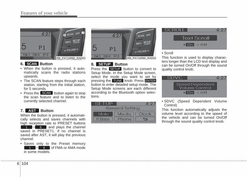
Features of your vehicle
1046
6. Button• When the button is pressed, it auto-
matically scans the radio stationsupwards.
• The SCAN feature steps through eachstation, starting from the initial station,for 5 seconds.
• Press the button again to stopthe scan feature and to listen to thecurrently selected channel.
7. ButtonWhen the button is pressed, it automati-cally selects and saves channels withhigh reception rate to PRESET buttons
~ and plays the channelsaved in PRESET1. If no channel issaved after AST, it will play the previouschannel.• Saves only to the Preset memory
~ of FMA or AMA modein some models.
8. ButtonPress the button to convert toSetup Mode. In the Setup Mode screen,select the mode you want to set bypressing the knob. Pressbutton to enter detailed setup mode. TheSetup Mode screens are each differentaccording to the Bluetooth option selec-tions.
• ScrollThis function is used to display charac-ters longer than the LCD text display andcan be turned On/Off through the soundquality control knob.
• SDVC (Speed Dependent VolumeControl)
This function automatically adjusts thevolume level according to the speed ofthe vehicle and can be turned On/Offthrough the sound quality control knob.
1 6
AST
SCAN
SCAN
TUNE ENTER
SETUPSETUP
1 6
RB_PA710RBI_RADIORB_PA710RBI_RADIO
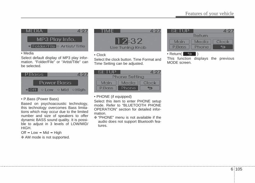
6 105
Features of your vehicle
• MediaSelect default display of MP3 play infor-mation. “Folder/File” or “Artist/Title” canbe selected.
• P.Bass (Power Bass)Based on psychoacoustic technology,this technology overcomes Bass limita-tions which may occur due to the limitednumber and size of speakers to offerdynamic BASS sound quality. It is possi-ble to adjust in 3 levels of LOW/MID/HIGH.Off ➟ Low ➟ Mid ➟ High❈ AM mode is not supported.
• ClockSelect the clock button. Time Format andTime Setting can be adjusted.
• PHONE (if equipped)Select this item to enter PHONE setupmode. Refer to “BLUETOOTH PHONEOPERATION” section for detailed infor-mation.❈ “PHONE” menu is not available if the
audio does not support Bluetooth fea-tures.
• Return( )This function displays the previousMODE screen.
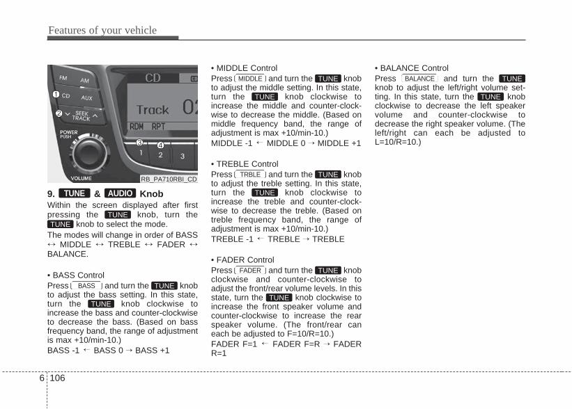
Features of your vehicle
1066
9. & KnobWithin the screen displayed after firstpressing the knob, turn the
knob to select the mode. The modes will change in order of BASS↔ MIDDLE ↔ TREBLE ↔ FADER ↔BALANCE.
• BASS ControlPress and turn the knobto adjust the bass setting. In this state,turn the knob clockwise toincrease the bass and counter-clockwiseto decrease the bass. (Based on bassfrequency band, the range of adjustmentis max +10/min-10.)BASS -1 BASS 0 → BASS +1
• MIDDLE ControlPress and turn the knobto adjust the middle setting. In this state,turn the knob clockwise toincrease the middle and counter-clock-wise to decrease the middle. (Based onmiddle frequency band, the range ofadjustment is max +10/min-10.)MIDDLE -1 MIDDLE 0 → MIDDLE +1
• TREBLE ControlPress and turn the knobto adjust the treble setting. In this state,turn the knob clockwise toincrease the treble and counter-clock-wise to decrease the treble. (Based ontreble frequency band, the range ofadjustment is max +10/min-10.)TREBLE -1 TREBLE → TREBLE
• FADER ControlPress and turn the knobclockwise and counter-clockwise toadjust the front/rear volume levels. In thisstate, turn the knob clockwise toincrease the front speaker volume andcounter-clockwise to increase the rearspeaker volume. (The front/rear caneach be adjusted to F=10/R=10.)FADER F=1 FADER F=R → FADERR=1
• BALANCE ControlPress and turn theknob to adjust the left/right volume set-ting. In this state, turn the knobclockwise to decrease the left speakervolume and counter-clockwise todecrease the right speaker volume. (Theleft/right can each be adjusted toL=10/R=10.)
TUNE
BASS TUNE
TUNETUNE
TUNE AUDIO
MIDDLE TUNE
→
TUNE
→
TUNE
TUNETRBLE
→
TUNE
TUNEFADER
→
TUNE
TUNE
BALANCE
RB_PA710RBI_CD
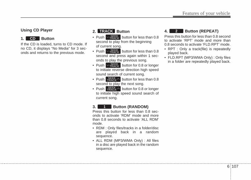
6 107
Features of your vehicle
Using CD Player
1. Button If the CD is loaded, turns to CD mode. Ifno CD, it displays “No Media” for 3 sec-onds and returns to the previous mode.
2. Button• Push button for less than 0.8
second to play from the beginningof current song.
• Push button for less than 0.8second and press again within 1 sec-onds to play the previous song.
• Push button for 0.8 or longerto initiate reverse direction high speedsound search of current song.
• Push button for less than 0.8second to play the next song.
• Push button for 0.8 or longerto initiate high speed sound search ofcurrent song.
3. Button (RANDOM)Press this button for less than 0.8 sec-onds to activate ‘RDM’ mode and morethan 0.8 seconds to activate ‘ALL RDM’mode.• RDM : Only files/tracks in a folder/disc
are played back in a randomsequence.
• ALL RDM (MP3/WMA Only) : All filesin a disc are played back in the randomsequence.
4. Button (REPEAT)Press this button for less than 0.8 secondto activate ‘RPT’ mode and more than0.8 seconds to activate ‘FLD.RPT’ mode.• RPT : Only a track(file) is repeatedly
played back.• FLD.RPT (MP3/WMA Only) : Only files
in a folder are repeatedly played back.
2
1
SEEKTRACK
SEEKTRACK
SEEKTRACK
SEEKTRACK
SEEKTRACK
TRACK
CD

Features of your vehicle
1086
5. CD Eject ButtonPush button for less than 0.8seconds to eject the CD during CD play-back. This button is enabled when igni-tion switch is off.
6. CD SlotPlease face printed side upward andgently push in. When the ignition switchis on ACC or ON and power is off, poweris automatically turned on if the CD isloaded. This CDP supports only 12cmCD. If VCD, Data CD are loaded,"Reading Error" message will appearand CD will be ejected.
7. ButtonPlay each song in the CD for 10 sec-onds. To cancel SCAN play, press thisbutton again.
8. ButtonDisplays the information of the currentCD TRACK(FILE) as below when thebutton is pressed each time.• CDDA : Disc Title, Disc Artist, Track
Title, Track Artist, Total Track• MP3/WMA : File Name, Title, Artist,
Album, Folder, Total File (not displayedif the information is not available on theDISC.)
9. Button• Press button to move to
child folder of the current folder anddisplay the first song in the folder.Press knob to move to the fold-er displayed. It will play the first song inthe folder.
• Press button to move toparent folder of the current folder anddisplay the first song in the folder.Press knob to move to the fold-er displayed.
10. Knob & Button
Turn this button clockwise to display thesongs next to the currently played song.Turn the button counterclockwise to dis-play the songs before the currentlyplayed song. Press the button to skip andplay the selected song.
ENTERTUNE
TUNE
FOLDER
TUNE
FOLDER
FOLDER
INFO
SCAN
RB_PA710RBI_CD

6 109
Features of your vehicle
Using USB device
1. Button (USB)If USB is connected, it switches to theUSB mode from the other mode to playthe song files stored in the USB. If no CDand auxiliary device is not connected, itdisplays "NO Media" for 3 seconds andreturns to the previous mode.
2. Button• Press the button for less
than 0.8 seconds to play from thebeginning of the current song. Press the button for less than 0.8 seconds and press it again within 1 sec-ond to move to and play the previoussong. Press the button for 0.8 seconds orlonger to play the song in reversedirection in fast speed.
• Press the button for lessthan 0.8 seconds to move to the nextsong. Press the button for 0.8 secondsor longer to play the song in forwarddirection in fast speed
3. Button (RANDOM)Press this button for less than 0.8 sec-onds to activate ‘RDM’ mode and morethan 0.8 seconds to activate ‘ALL RDM’mode. • RDM : Only files in a folder are played
back in a random sequence.• ALL RDM : All files in a USB memory
are played back in the randomsequence.
4. Button (REPEAT)Press this button for less than 0.8 sec-onds to activate ‘RPT’ mode and morethan 0.8 seconds to activate ‘FLD.RPT’mode.• RPT : Only a file is repeatedly played
back. • ‘FLD.RPT’ : All files in a folder are
repeatedly played back.
2
1
SEEKTRACK
SEEKTRACK
TRACK
AUX
RB_PA710RBI_USB

Features of your vehicle
1106
5. ButtonPlays each song in the USB device for10 seconds.To cancel SCAN play, press this buttonagain.
6. ButtonDisplays the information of the file cur-rently played in the order of File Name,Title, Artist, Album, Folder, Total File,Normal Display (Displays no informationif the file has no song information.)
7. Button• Press button to move to
child folder of the current folder anddisplay the first song in the folder.Press / knob to moveto the folder displayed. It will play thefirst song in the folder.
• Press button to move toparent folder display the first song inthe folder. Press / knob to moveto the folder displayed.
8. Knob & ButtonTurn this button clockwise to display thesongs next to the currently played song.Turn the button counterclockwise to dis-play the songs before the currentlyplayed song. Press the button to skip andplay the selected song.
ENTERTUNE
ENTERTUNE
FOLDER
ENTERTUNE
FOLDER
FOLDER
INFO
SCAN
RB_PA710RBI_USB RB_PA710RBI_USB

6 111
Features of your vehicle
CAUTION IN USING USBDEVICE
• To use an external USB device,make sure the device is not con-nected when starting up the vehi-cle. Connect the device afterstarting up.
• If you start the engine when theUSB device is connected, it maydamage the USB device. (USBflashdrives are very sensitive toelectric shock.)
• If the engine is started up orturned off while the external USBdevice is connected, the externalUSB device may not work.
• It may not play inauthentic MP3 orWMA files.1) It can only play MP3 files with
the compression rate between8Kbps~320Kbps.
2) It can only play WMA musicfiles with the compression ratebetween 8Kbps~320Kbps.
• Take precautions for static elec-tricity when connecting or dis-connecting the external USBdevice.
(Continued)
(Continued)• An encrypted MP3 PLAYER is not
recognizable.• Depending on the condition of
the external USB device, the con-nected external USB device canbe unrecognizable.
• When the formatted byte/sectorsetting of External USB device isnot either 512BYTE or 2048BYTE,then the device will not be recog-nized.
• Use only a USB device formattedto FAT 12/16/32.
• USB devices without USB I/Fauthentication may not be recog-nizable.
• Make sure the USB connectionterminal does not come in con-tact with the human body or otherobjects.
• If you repeatedly connect or dis-connect the USB device in a shortperiod of time, it may break thedevice.
• You may hear a strange noisewhen connecting or disconnect-ing a USB device.
(Continued)
(Continued)• If you disconnect the external
USB device during playback inUSB mode, the external USBdevice can be damaged or maymalfunction. Therefore, discon-nect the external USB devicewhen the audio is turned off or inanother mode. (e.g, Radio or CD)
• Depending on the type andcapacity of the external USBdevice or the type of the filesstored in the device, there is a dif-ference in the time taken forrecognition of the device.
• Do not use the USB device forpurposes other than playingmusic files.
• Playing videos through the USBis not supported.
• Use of USB accessories such asrechargers or heaters using USBI/F may lower performance orcause trouble.
(Continued)

Features of your vehicle
1126
(Continued)• If you use devices such as a USB
hub purchased separately, thevehicle’s audio system may notrecognize the USB device. In thatcase, connect the USB devicedirectly to the multimedia termi-nal of the vehicle.
• If the USB device is divided bylogical drives, only the musicfiles on the highest-priority driveare recognized by car audio.
• Devices such as MP3 Player/Cellular phone/Digital camera canbe unrecognizable by standardUSB I/F can be unrecognizable.
• Charging through the USB maynot be supported in some mobiledevices.❋ A car exclusive cable (Provided
or sold separately) is requiredto use the iPod.
• Some non-standard USB devices(METAL COVER TYPE USB) canbe unrecognizable.
• Some USB flash memory readers(such as CF, SD, microSD, etc.) orexternal-HDD type devices can beunrecognizable.
(Continued)
(Continued)• Music files protected by DRM
(DIGITAL RIGHTS MANAGE-MENT) are not recognizable.
• The data in the USB memory maybe lost while using this audio.Always back up important dataon a personal storage device.
• Please avoid using USB memoryproducts which can be used askey chains or cellular phoneaccessories as they could causedamage to the USB jack. Pleasemake certain only to use plugtype connector products asshown below.

6 113
Features of your vehicle
Using iPod❋ iPod is a trademark of Apple Inc.
1. Button (iPod)If iPod is connected, it switches to theiPod mode from the previous mode toplay the song files stored in the iPod.If there is no iPod connected, then it dis-plays the message "No Media" for 3 sec-onds and returns to the previous mode.
2. Button• Press the button for less
than 0.8 seconds to play from thebeginning of the song currently played. Press the button for less than 0.8 sec-onds and press it again within 1 sec-ond to move to and play the previoustrack. Press the button for 0.8 seconds orlonger to play the song in reversedirection in fast speed.
• Press the button for lessthan 0.8 seconds to move to the nexttrack.Press the button for 0.8 seconds orlonger to play the song in forwarddirection in fast speed.
3. Button (RANDOM)• Press this button for less than 0.8 sec-
onds to shuffle order of all songs incurrent category. (Song Random)
• Press this button for 0.8 seconds orlonger to shuffle order of albums in cur-rent category. (Album Random)
• To cancel RANDOM Play, press thisbutton again..
4. Button (REPEAT)Repeats the song currently played.
2
1
SEEKTRACK
SEEKTRACK
TRACK
AUX
RB_PA710RBI_iPod

Features of your vehicle
1146
5. Button (MENU) Moves to the upper category from cur-rently played category of the iPod. To move to (play) the category (song)displayed, press knob.You will be able to search through thelower category of the selected category.The order of iPod’s category is Playlist,Artist, Albums, Genres, Songs,Composers.
6. Knob & ButtonWhen you rotate the knob clockwise, itwill display the songs (category) aheadof the song currently played (category inthe same level).Also, when you rotate the knob counter-clockwise, it will display the songs (cate-gory) before the song currently played(category in the same level).To listen to the song displayed in thesong category, press the button to skip toand play the selected song.
7. ButtonDisplays the information of the file cur-rently played in the order of Title, Artist ,Album, Normal Display (Displays noinformation if the file has no song infor-mation.)
INFO
TUNE ENTER
TUNE
6
RB_PA710RBI_iPodRB_PA710RBI_iPod

6 115
Features of your vehicle
✽ NOTICE FOR USING THEiPod DEVICE
• Some iPod models might not supportthe communication protocol and thefiles will not be played. Supported iPod models: - iPod Mini- iPod 4th(Photo) ~ 6th(Classic)generation- iPod Nano 1st~4th generation- iPod Touch 1st~2nd generation
• The order of search or playback ofsongs in the iPod can be differentfrom the order searched in the audiosystem.
• If the iPod disabled due to its ownmalfunction, reset the iPod. (Reset:Refer to iPod manual)
• An iPod may not operate normally onlow battery.
• Some iPod devices, such as theiPhone, can be connected through theBluetooth® interface. The device musthave audio Bluetooth® capability(such as for stereo headphoneBluetooth®). The device can play, butit will not be controlled by the audiosystem.
CAUTION IN USING THEiPod DEVICE
• The Hyundai iPod Power Cable isneeded in order to operate iPodwith the audio buttons on theaudio system. The USB cable pro-vided by Apple may cause mal-function and should not be usedfor Hyundai vehicles.❋ The Hyundai iPod Power Cable
may be purchased throughyour Hyundai Dealership.
• When connecting iPod with theiPod Power Cable, insert the con-nector to the multimedia socketcompletely. If not inserted com-pletely, communications betweeniPod and audio may be interrupt-ed.
• When adjusting the sound effectsof the iPod and the audio system,the sound effects of both deviceswill overlap and might reduce ordistort the quality of the sound.
• Deactivate (turn off) the equalizerfunction of an iPod when adjust-ing the audio system’s volume,and turn off the equalizer of theaudio system when using theequalizer of an iPod.
(Continued)
(Continued)• When the iPod cable is connect-
ed, the system can be switched toAUX mode even without iPoddevice and may cause noise.Disconnect the iPod cable whenyou are not using the iPod device.
• When not using iPod with caraudio, detach the iPod cable fromiPod. Otherwise, iPod may remainin accessory mode, and may notwork properly.
• When connecting the iPod, usethe USB/AUX terminals.
• When disconnecting the iPod,disconnect both the USB/AUXterminal.
• The iPod exclusive cable must beconnected to both the USB/AUXterminals for iPod charging andoperations to be supported.
Detachable USB/AUX All-in-one USB/AUX
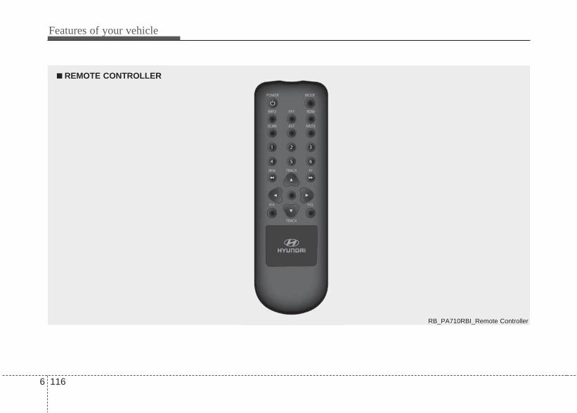
Features of your vehicle
1166
■ REMOTE CONTROLLER
RB_PA710RBI_Remote Controller

6 117
Features of your vehicle
REMOTE CONTROLLER
1. Button Turns the set on/off when the IGNITIONSWITCH is on ACC or ON.
2. ButtonWhen the button is pressed continually,the audio mode is changed in sequence.If a CD has not been inserted, the audiowill skip a CD mode.FM1 ➟ FM2 ➟ AM ➟ CD ➟ FM1···.
3. ButtonDisplays the information of the currentCD TRACK in the order of DISC TITLE,DISC ARTIST, TRACK TITLE, TRACKARTIST, TOTAL TRACK, Play Screen.(not displayed if the information is notavailable on the DISC.)
4. ButtonPress this button for less than 0.8 sec-onds to activate 'RPT' mode and morethan 0.8 seconds to activate 'FLD.RPT'mode.• RPT : Only a file is repeatedly played
back.• FLD.RPT : All files in a folder are rea-
peatedly played back.
5. ButtonPress this button for less than 0.8 sec-onds to activate 'RDM' mode and morethan 0.8 seconds to activate 'ALL RDM'mode.• RDM : Only files in a folder are played
back in a random sequence.• ALL RDM : All files in a USB memory
are played back in the randomsequence.
6. Button• Radio mode Play first 10 seconds of
each channel in the preset button.• CD mode Play first 10 seconds of each
song in the DISC.To cancel the mode, press the buttononce again.
7. Button (AUTOSTORE)When the button is pressed, it automati-cally selects and saves channels withhigh reception rate to PRESET buttons
~ and plays the channelsaved in PRESET1.If no channel is saved after AST, it willplay the previous channel.
8. ButtonWhen inputting button, indicate“Audio Mute” at the same time with out-put MUTE.“Mute the microphone during a call”
MUTE
MUTE
61
AST
SCAN
RDM
RPT
INFO
MODE
POWER
PA710RBI_Remote Controller

Features of your vehicle
1186
9. PRESET ButtonRadio mode Push ~ but-tons less than 0.8 second to play thechannel saved in each button.Push ~ buttons for 0.8second or longer to save current channelto the respective button with a beep.
10. / ButtonCD mode When the or button is pressed, the current song isrewinded or played fast forward.
11. Button (VOLUME)This button controls the volume.
12. ButtonRadio mode• When the button is
pressed, it reduces the band frequencyto automatically select channel. Stopsat the previous frequency if no channelis found.
• When the button ispressed, it increases the band fre-quency to automatically select chan-nel. Stops at the previous frequency ifno channel is found.
CD mode• Push button for less than
0.8 second to play from the beginningof current song.
• Push button for less than0.8 second and press again within1 second to play the previous song.
• Push button for less than0.8 second to play the next song.
13. No Function ButtonThe buttons have not any Function.
61
61
FFREWFFREW
VOL
TRACK ▲
TRACK ▼
TRACK
TRACK ▲
TRACK ▼
TRACK ▼
PA710RBI_Remote Controller
PA710RBI_Remote Controller
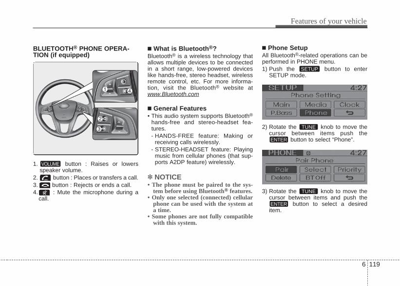
6 119
Features of your vehicle
BLUETOOTH® PHONE OPERA-TION (if equipped)
1. button : Raises or lowersspeaker volume.
2. button : Places or transfers a call.3. button : Rejects or ends a call.4. : Mute the microphone during a
call.
■ What is Bluetooth®?Bluetooth® is a wireless technology thatallows multiple devices to be connectedin a short range, low-powered deviceslike hands-free, stereo headset, wirelessremote control, etc. For more informa-tion, visit the Bluetooth® website atwww.Bluetooth.com
■ General Features• This audio system supports Bluetooth®
hands-free and stereo-headset fea-tures.- HANDS-FREE feature: Making or
receiving calls wirelessly.- STEREO-HEADSET feature: Playing
music from cellular phones (that sup-ports A2DP feature) wirelessly.
✽ NOTICE• The phone must be paired to the sys-
tem before using Bluetooth® features.• Only one selected (connected) cellular
phone can be used with the system ata time.
• Some phones are not fully compatiblewith this system.
■ Phone SetupAll Bluetooth®-related operations can beperformed in PHONE menu.1) Push the button to enter
SETUP mode.
2) Rotate the knob to move thecursor between items push the
button to select “Phone”.
3) Rotate the knob to move thecursor between items and push the
button to select a desireditem.ENTER
TUNE
ENTER
TUNE
SETUP
VOLUME

Features of your vehicle
1206
• Pairing a phoneBefore using Bluetooth® features, thephone must be paired (registered) withthe audio system. Up to 5 phones can bepaired with the system.
NOTE: • The pairing procedure of the phone
varies according to each phonemodel. Before attempting to pairphone, please see your phone’sUser’s Guide for instructions.
• Once pairing with the phone is com-pleted, there is no need to pair withthat phone again unless the phoneis deleted manually from the audiosystem (refer “Deleting a Phone”section) or the vehicle’s informationis removed from the phone.
1. Press button to enter SETUPmode.
2. Select “PHONE”, then “PAIR” inPHONE menu.
3. The audio displays “searching ----passkey: 0000”
4. Search the Bluetooth® system on yourphone .Your phone should displayyour [vehicle model name] on theBluetooth® device list. Then attemptpairing on your phone.
NOTE: If the phone is paired to two or morevehicles of the same model, i.e. bothvehicles are HYUNDAI VERNA, somephones may not handle Bluetooth®
devices of that name correctly. In thiscase, you may need to change thename displayed on your phone fromVerna to Verna1 and Verna2. Refer to your phone’s User’s Guide,or contact your cellular carrier orphone manufacturer for instructions.
• Connecting a phoneWhen the Bluetooth® system is enabled,the phone previously used is automati-cally selected and re-connected. If youwant to select different phone previouslypaired, the phone can be selectedthrough “Select Phone” menu.Only a selected phone can be used withthe hands-free system at a time.1. Press button to enter SETUPmode.2. Select “PHONE”, then “Select” in
PHONE menu.3. Select desired phone name from the
list shown.
SETUP
SETUP
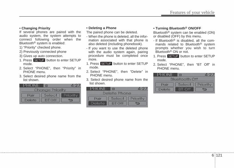
6 121
Features of your vehicle
• Changing PriorityIf several phones are paired with theaudio system, the system attempts toconnect following order when theBluetooth® system is enabled:1) “Priority” checked phone.2) Previously connected phone3) Gives up auto connection.1. Press button to enter SETUP
mode.2. Select “PHONE”, then “Priority” in
PHONE menu.3. Select desired phone name from the
list shown.
• Deleting a PhoneThe paired phone can be deleted.- When the phone is deleted, all the infor-
mation associated with that phone isalso deleted (including phonebook).
- If you want to use the deleted phonewith the audio system again, pairingprocedure must be completed oncemore.
1. Press button to enter SETUPmode.
2. Select “PHONE”, then “Delete” inPHONE menu.
3. Select desired phone name from thelist shown.
• Turning Bluetooth® ON/OFFBluetooth® system can be enabled (ON)or disabled (OFF) by this menu.- If Bluetooth® is disabled, all the com-
mands related to Bluetooth® systemprompts whether you wish to turnBluetooth® ON or not.
1. Press button to enter SETUPmode.
2. Select “PHONE”, then “BT Off” inPHONE menu.
SETUP
SETUPSETUP

Features of your vehicle
1226
■ Receiving a Phone CallWhen receiving a phone call, a ringtoneis audible from speakers and the audiosystem changes into telephone mode.When receiving a phone call, “Incoming”message and incoming phone number (if available) are displayed on the audio.• To Answer a Call:- Press button on the steering
wheel.• To Reject a Call:- Press button on the steering
wheel.• To Adjust Ring Volume:- Use VOLUME buttons on the steering
wheel.• To Transfer a Call to the Phone(Private
Call):- Press and hold button on the
steering wheel until the audio systemtransfers a call to the phone.
■ Talking on the PhoneWhen talking on the phone, “ActiveCalls” message and the other party’sphone number (if available) are dis-played on the audio.• To Mute the Microphone- Press button on the audio.• To Finish a Call- Press button on the steering
wheel.
■ Making a Phone CallA Call Back can be made by pressing
button on the steering wheel.- This is the same function as using the
button solely on the cellularphone.
NOTE: Some phone models require pressing
button twice to make a call.
✽ NOTICEIn the following situations, you or theother party may have difficulty hearingeach other:1. Speaking at the same time, your voice
may not reach each other parties.(This is not a malfunction.) Speakalternately with the other party on thephone.
2. Keep the Bluetooth® volume to a lowlevel. High-level volume may result indistortion and echo.
3. When driving on a rough road.4. When driving at high speeds.5. When the window is open.6. When the air conditioning vents are
facing the microphone.7. When the sound of the air condition-
ing fan is loud.

6 123
Features of your vehicle
■ Bluetooth® Audio MusicStreaming
This audio system supports A2DP (AudioAdvanced Distribution Profile) andAVRCP(Audio Video Remote ControlProfile). Both profiles are available for listening tothe MP3 music via Bluetooth cellularphone supporting above Bluetooth pro-files. To play MP3 music from the Bluetoothcellular phone, press the buttonuntil “MP3 Play” is displayed on the LCD.Then try playing music by phone.When playing music from the Bluetooth cellular phone, the head unit displaysMP3 MODE.
NOTE:• Not only MP3 files, all the sounds
that the phone supports can beheard by the audio system.
• The Bluetooth cellular phones shallfeature A2DP and AVRCP functions.
• Some A2DP and AVRCP Bluetoothcellular phones may not play musicthrough the head unit on first try.Please try the below; i.e : Menu➟Filemanager➟Music➟
Option➟Play via Bluetooth • Please refer to User's Guide of your
phone for more.To stop music, try stop playingmusic from the phone then changethe audio mode to other than “MP3Play” mode (e.g. FM, AM, CD, etc.)
AUX
Features of your vehicle
1246
CAUTION IN USINGBLUETOOTH® CELLU-LAR PHONE
• Do not use a cellular phone orperform Bluetooth® settings (e.g.pairing a phone) while driving.
• Some Bluetooth®-enabledphones may not be recognized bythe system or fully compatiblewith the system.
• Before using Bluetooth® relatedfeatures of the audio system,refer your phone’s User’s Manualfor phone-side Bluetooth® opera-tions.
• The phone must be paired to theaudio system to use Bluetooth®
related features.• You will not be able to use the
hands-free feature when yourphone (in the car) is outside ofthe cellular service area (e.g. in atunnel, in a underground, in amountainous area, etc.).
• If the cellular phone signal is pooror the vehicles interior noise istoo loud, it may be difficult tohear the other person’s voice dur-ing a call.
(Continued)
(Continued)• Do not place the phone near or
inside metallic objects, otherwise communications with Bluetooth®
system or cellular service sta-tions can be disturbed.
• While a phone is connectedthrough Bluetooth® your phonemay discharge quicker than usualfor additional Bluetooth®-relatedoperations.
• Some cellular phones or otherdevices may cause interferencenoise or malfunction to audiosystem. In this case, store thedevice in a different location mayresolve the situation.
• Please save your phone name inEnglish, or your phone name maynot be displayed correctly.
Before driving / 7-3Key / 7-5Engine Start/Stop button / 7-8Manual transaxle / 7-14Automatic transaxle / 7-17Brake system / 7-23Economical operation / 7-30Special driving conditions / 7-32Winter driving / 7-36Vehicle weight / 7-39
7Driving your vehicle

Driving your vehicle
27
WARNING - ENGINE EXHAUST CAN BE DANGEROUS!Engine exhaust fumes can be extremely dangerous. If, at any time, you smell exhaust fumes inside the vehicle, open the win-dows immediately.
• Do not inhale exhaust fumes.Exhaust fumes contain carbon monoxide, a colorless, odorless gas that can cause unconsciousness and death by asphyxia-tion.
• Be sure the exhaust system does not leak.The exhaust system should be checked whenever the vehicle is raised to change the oil or for any other purpose. If you heara change in the sound of the exhaust or if you drive over something that strikes the underneath side of the car, have theexhaust system checked as soon as possible. We recommend to have it done by an authorized HYUNDAI dealer.
• Do not run the engine in an enclosed area.Letting the engine idle in your garage, even with the garage door open, is a hazardous practice. Never run the engine in yourgarage any longer than it takes to start the engine and back the car out.
• Avoid idling the engine for prolonged periods with people inside the car.If it is necessary to idle the engine for a prolonged period with people inside the car, be sure to do so only in an open areawith the air intake set at "Fresh" and fan operating at one of the higher speeds so fresh air is drawn into the interior.
If you must drive with the trunk lid open because you are carrying objects that make this necessary:1. Close all windows.2. Open side vents.3. Set the air intake control at "Fresh", the air flow control at "Floor" or "Face" and the fan at one of the higher speeds.
To assure proper operation of the ventilation system, be sure the ventilation air intakes located just in front of the windshield arekept clear of snow, ice, leaves or other obstructions.

7 3
Driving your vehicle
Before entering vehicle• Be sure that all windows, outside mir-
ror(s), and outside lights are clean.• Check the condition of the tires.• Check under the vehicle for any sign of
leaks.• Be sure there are no obstacles behind
you if you intend to back up.
Necessary inspections Fluid levels, such as engine oil, enginecoolant, brake fluid, and washer fluidshould be checked on a regular basis,with the exact interval depending on thefluid. Further details are provided in sec-tion 7, “Maintenance”.
Before starting • Close and lock all doors.• Position the seat so that all controls
are easily reached.• Adjust the inside and outside rearview
mirrors.• Be sure that all lights work.• Check all gauges.• Check the operation of warning lights
when the ignition switch is turned tothe ON position.
• Release the parking brake and makesure the brake warning light goes out.
For safe operation, be sure you are famil-iar with your vehicle and its equipment.
BEFORE DRIVING
WARNINGAll passengers must be properlybelted whenever the vehicle ismoving. Refer to “Seat belts” insection 3 for more information ontheir proper use.
WARNINGAlways check the surroundingareas near your vehicle for people,especially children, before puttinga car into D (Drive) or R (Reverse).
WARNINGDriving while distracted can resultin a loss of vehicle control, thatmay lead to an accident, severepersonal injury, and death. The dri-ver’s primary responsibility is inthe safe and legal operation of avehicle, and use of any handhelddevices, other equipment, or vehi-cle systems which take the driver’seyes, attention and focus awayfrom the safe operation of a vehicleor which are not permissible by lawshould never be used during oper-ation of the vehicle.

WARNING - Driving underthe influence of alcohol ordrugs
Drinking and driving is dangerous.Drunk driving is the number onecontributor to the highway deathtoll each year. Even a small amountof alcohol will affect your reflexes,perceptions and judgment. Drivingwhile under the influence of drugsis as dangerous or more dangerousthan driving drunk.You are much more likely to have aserious accident if you drink ortake drugs and drive.If you are drinking or taking drugs,don’t drive. Do not ride with a driv-er who has been drinking or takingdrugs. Choose a designated driveror call a cab.
WARNING• When you intend to park or stop
the vehicle with the engine on, becareful not to depress the accel-erator pedal for a long period oftime. It may overheat the engineor exhaust system and cause fire.
• When you make a sudden stop orturn the steering wheel rapidly,loose objects may drop on thefloor and it could interfere withthe operation of the foot pedals,possibly causing an accident.Keep all things in the vehiclesafely stored.
• If you do not focus on driving, itmay cause an accident. Be care-ful when operating what may dis-turb driving such as audio orheater. It is the responsibility ofthe driver to always drive safely.
7 4
Driving your vehicle

Ignition switch positionLOCKThe steering wheel locks to protectagainst theft. The ignition key can beremoved only in the LOCK position.When turning the ignition switch to theLOCK position, push the key inward atthe ACC position and turn the key towardthe LOCK position.
ACC (Accessory)The steering wheel is unlocked and elec-trical accessories are operative.
✽✽ NOTICEIf difficulty is experienced turning theignition switch to the ACC position, turnthe key while turning the steering wheelright and left to release the tension.
ONThe warning lights can be checkedbefore the engine is started. This is thenormal running position after the engineis started.Do not leave the ignition switch ON if theengine is not running to prevent the bat-tery from discharging.
STARTTurn the ignition switch to the STARTposition to start the engine. The enginewill crank until you release the key; thenit returns to the ON position. The brakewarning lamp can be checked in thisposition.
KEY
ORBC050001
WARNING - Ignition key• Never turn the ignition switch to
LOCK or ACC while the vehicle ismoving. This would result in lossof directional control and brakingfunction, which could cause anaccident.
• The anti-theft steering column lockis not a substitute for the parkingbrake. Before leaving the driver’sseat, always make sure the shiftlever is engaged in 1st gear for themanual transaxle or P (Park) forthe automatic transaxle, set theparking brake fully and shut theengine off. Unexpected and sud-den vehicle movement may occurif these precautions are not taken.
• Never reach for the ignition switch,or any other controls through thesteering wheel while the vehicle isin motion. The presence of yourhand or arm in this area couldcause a loss of vehicle control, anaccident and serious bodily injuryor death.
• Do not place any movable objectsaround the driver’s seat as theymay move while driving, interferewith the driver and lead to an acci-dent.
Driving your vehicle
57

Starting the engine Starting the gasoline engine(if equipped)1.Make sure the parking brake is
applied.2. Manual Transaxle - Depress the
clutch pedal fully and shift thetransaxle into Neutral. Keep the clutchpedal and brake pedal depressedwhile turning the ignition switch to thestart position. Automatic Transaxle - Place thetransaxle shift lever in P (Park).Depress the brake pedal fully.You can also start the engine whenthe shift lever is in the N (Neutral)position.
3. Turn the ignition switch to START andhold it there until the engine starts (amaximum of 10 seconds), thenrelease the key.
4. In extremely cold weather (below -18°C / 0°F) or after the vehicle hasnot been operated for several days, letthe engine warm up without depress-ing the accelerator.
Whether the engine is cold or warm, itshould be started without depressingthe accelerator.
WARNINGAlways wear appropriate shoeswhen operating your vehicle.Unsuitable shoes (high heels, skiboots,etc.) may interfere with yourability to use the brake and acceler-ator pedal, and the clutch (ifequipped).
CAUTIONIf the engine stalls while you are inmotion, do not attempt to move theshift lever to the P (Park) position. Iftraffic and road conditions permit,you may put the shift lever in the N(Neutral) position while the vehicleis still moving and turn the ignitionswitch to the START position in anattempt to restart the engine.
CAUTIONDo not engage the starter for morethan 10 seconds. If the engine stallsor fails to start, wait 5 to 10 secondsbefore re-engaging the starter.Improper use of the starter maydamage it.
7 6
Driving your vehicle
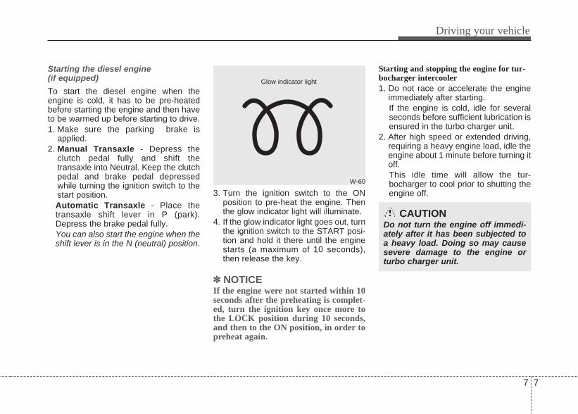
Starting the diesel engine(if equipped)
To start the diesel engine when theengine is cold, it has to be pre-heatedbefore starting the engine and then haveto be warmed up before starting to drive.1. Make sure the parking brake is
applied.2. Manual Transaxle - Depress the
clutch pedal fully and shift thetransaxle into Neutral. Keep the clutchpedal and brake pedal depressedwhile turning the ignition switch to thestart position. Automatic Transaxle - Place thetransaxle shift lever in P (park).Depress the brake pedal fully.You can also start the engine when theshift lever is in the N (neutral) position.
3. Turn the ignition switch to the ONposition to pre-heat the engine. Thenthe glow indicator light will illuminate.
4. If the glow indicator light goes out, turnthe ignition switch to the START posi-tion and hold it there until the enginestarts (a maximum of 10 seconds),then release the key.
✽✽ NOTICEIf the engine were not started within 10seconds after the preheating is complet-ed, turn the ignition key once more tothe LOCK position during 10 seconds,and then to the ON position, in order topreheat again.
Starting and stopping the engine for tur-bocharger intercooler 1. Do not race or accelerate the engine
immediately after starting.If the engine is cold, idle for severalseconds before sufficient lubrication isensured in the turbo charger unit.
2. After high speed or extended driving,requiring a heavy engine load, idle theengine about 1 minute before turning itoff.This idle time will allow the tur-bocharger to cool prior to shutting theengine off.
W-60
Glow indicator light
CAUTIONDo not turn the engine off immedi-ately after it has been subjected toa heavy load. Doing so may causesevere damage to the engine orturbo charger unit.
Driving your vehicle
77

Illuminated engine start/stop but-tonWhenever the front door is opened, theengine start/stop button will illuminate foryour convenience. The light will go offafter about 30 seconds when the door isclosed.
Engine start/stop button positionOFF
• With manual transaxleTo turn off the engine (START/RUNposition) or vehicle power (ON posi-tion), stop the vehicle then press theengine start/stop button.
• With automatic transaxleTo turn off the engine (START/RUNposition) or vehicle power (ON posi-tion), press the engine start/stop buttonwith the shift lever in the P (Park) posi-tion. When you press the enginestart/stop button without the shift leverin the P (Park) position, the enginestart/stop button will not change to theOFF position but to the ACC position.Also, the steering wheel locks when theengine start/stop button is in the OFFposition to protect you against theft. Itlocks when the door is opened.
If the steering wheel is not locked prop-erly when you open the driver's door,the warning chime will sound. Try lock-ing the steering wheel again. If theproblem is not solved, we recommendto have it checked by an authorizedHYUNDAI dealer.In addition, if the engine start/stop but-ton is in the OFF position after the dri-ver's door is opened, the steering wheelwill not lock and the warning chime willsound. In such a situation, close thedoor. Then the steering wheel will lockand the warning chime will stop.
✽✽ NOTICEIf the steering wheel doesn't unlockproperly, the engine start/stop buttonwill not work. Press the enginestart/stop button while turning thesteering wheel right and left to releasethe tension.
ENGINE START/STOP BUTTON (IF EQUIPPED)
ORBI051005
Not illuminated
7 8
Driving your vehicle

ACC(Accessory)
• With manual transaxlePress the engine start/stop button whenthe button is in the OFF position withoutdepressing the clutch pedal.
• With automatic transaxlePress the engine start/stop button whileit is in the OFF position withoutdepressing the brake pedal.The steering wheel unlocks and electri-cal accessories are operational. If the engine start/stop button is in theACC position for more than 1 hour, thebutton is turned off automatically to pre-vent battery discharge.
ON
• With manual transaxlePress the engine start/stop button whenthe button is in the ACC position withoutdepressing the clutch pedal.
• With automatic transaxlePress the engine start/stop button whileit is in the ACC position withoutdepressing the brake pedal. The warning lights can be checkedbefore the engine is started. Do notleave the engine start/stop button in theON position for a long time. The batterymay discharge, because the engine isnot running.
Orange indicator Blue indicator
CAUTIONYou are able to turn off the engine(START/RUN) or vehicle power (ON),only when the vehicle is not inmotion. In an emergency situationwhile the vehicle is in motion, you areable to turn the engine off and to theACC position by pressing the enginestart/stop button for more than 2 sec-onds or 3 times successively within 3seconds. If the vehicle is still moving,you can restart the engine withoutdepressing the brake pedal by press-ing the engine start/stop button withthe shift lever in the N (Neutral) posi-tion.
Driving your vehicle
97

START/RUN
• With manual transaxleTo start the engine, depress the clutchpedal and brake pedal, then press theengine start/stop button with the shiftlever in the N (Neutral) position.
• With automatic transaxleTo start the engine, depress the brakepedal and press the engine start/stopbutton with the shift lever in the P (Park)or the N (Neutral) position. For yoursafety, start the engine with the shiftlever in the P (Park) position.
✽✽ NOTICEIf you press the engine start/stop buttonwithout depressing the clutch pedal formanual transaxle vehicles or withoutdepressing the brake pedal for automat-ic transaxle vehicles, the engine will notstart and the engine start/stop buttonchanges as follow:OFF ➔ACC ➔ ON ➔ OFF or ACC
✽ NOTICEIf you leave the engine start/stop buttonin the ACC or ON position for a longtime, the battery will discharge.
WARNING• Never press the engine start/stop
button while the vehicle is inmotion. This would result in lossof directional control and brakingfunction, which could cause anaccident.
• The anti-theft steering columnlock is not a substitute for theparking brake. Before leaving thedriver's seat, always make surethe shift lever is engaged in P(Park), set the parking brake fullyand shut the engine off.Unexpected and sudden vehiclemovement may occur if theseprecautions are not taken.
(Continued)
(Continued)• Never reach for the engine start/
stop button or any other controlsthrough the steering wheel whilethe vehicle is in motion. The pres-ence of your hand or arm in thearea could cause loss of vehiclecontrol, an accident and seriousbodily injury or death.
• Do not place any movableobjects around the driver's seatas they may move while driving,interfere with the driver and leadto an accident.
Not illuminated
7 10
Driving your vehicle

Starting the engine Starting the gasoline engine (if equipped)1. Carry the smart key or leave it inside
the vehicle. 2. Make sure the parking brake is firmly
applied.3. Manual Transaxle - Depress the
clutch pedal fully and shift thetransaxle into Neutral. Keep the clutchpedal and brake pedal depressedwhile starting the engine. Automatic Transaxle - Place thetransaxle shift lever in P (Park).Depress the brake pedal fully.You can also start the engine whenthe shift lever is in the N (Neutral)position.
4. Press the engine start/stop button.5. In extremely cold weather (below -
18°C / 0°F) or after the vehicle has notbeen operated for several days, let theengine warm up without depressingthe accelerator. Whether the engine is cold or warm, itshould be started without depressingthe accelerator.
Starting the diesel engine (if equipped)
To start the diesel engine when theengine is cold, it has to be pre-heatedbefore starting the engine and then haveto be warmed up before starting to drive.1. Make sure the parking brake is
applied.2. Manual Transaxle - Depress the
clutch pedal fully and shift thetransaxle into Neutral. Keep the clutchpedal and brake pedal depressedwhile pressing the engine start/stopbutton to the START position. Automatic Transaxle - Place thetransaxle shift lever in P (Park).Depress the brake pedal fully.You can also start the engine when theshift lever is in the N (Neutral) position.
WARNINGAlways wear appropriate shoeswhen operating your vehicle.Unsuitable shoes (high heels, skiboots,etc.) may interfere with yourability to use the brake and acceler-ator pedal.
Driving your vehicle
117

3. Press the engine start/stop buttonwhile depressing the brake pedal.
4. Continue depressing the brake pedaluntil the illuminated glow indicatorgoes off. (approximately 5 seconds)
5. The engine starts running when theglow indicator goes off.
✽✽ NOTICEIf the engine start/stop button is pressedonce more while the engine is pre-heat-ing, the engine may start.
Starting and stopping the engine for tur-bocharger intercooler 1. Do not race or accelerate the engine
immediately after starting.If the engine is cold, idle for severalseconds before sufficient lubrication isensured in the turbocharger unit.
2. After high speed or extended driving,requiring a heavy engine load, idle theengine about 1 minute before turning itoff.This idle time will allow the tur-bocharger to cool prior to shutting theengine off.
• Even if the smart key is in the vehicle,if it is far away from you, the enginemay not start.
• When the engine start/stop button is inthe ACC position or above, if any dooris opened, the system checks for thesmart key. If the smart key is not in thevehicle, the " " indicator will blinkor the warning "Key is not in vehicle"will illuminate on the LCD display. Andif all doors are closed, the chime willsound for 5 seconds. The indicator orwarning will turn off while the vehicle ismoving. Always have the smart keywith you.
WARNINGThe engine will start, only when thesmart key is in the vehicle. Never allow children or any personwho is unfamiliar with the vehicletouch the engine start/stop buttonor related parts.
CAUTIONDo not turn the engine off immedi-ately after it has been subjected toa heavy load. Doing so may causesevere damage to the engine or tur-bocharger unit.
W-60
Glow indicator light
7 12
Driving your vehicle
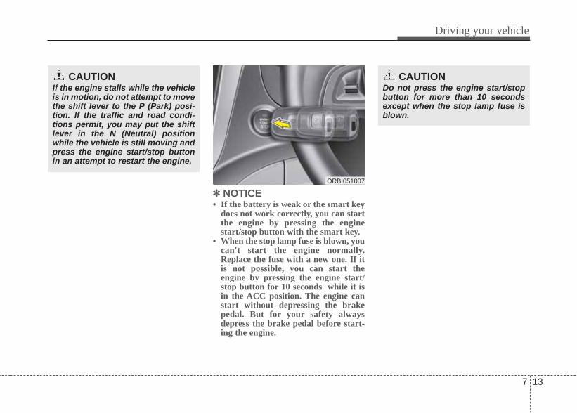
✽✽ NOTICE• If the battery is weak or the smart key
does not work correctly, you can startthe engine by pressing the enginestart/stop button with the smart key.
• When the stop lamp fuse is blown, youcan't start the engine normally.Replace the fuse with a new one. If itis not possible, you can start theengine by pressing the engine start/stop button for 10 seconds while it isin the ACC position. The engine canstart without depressing the brakepedal. But for your safety alwaysdepress the brake pedal before start-ing the engine.
CAUTIONDo not press the engine start/stopbutton for more than 10 secondsexcept when the stop lamp fuse isblown.
CAUTIONIf the engine stalls while the vehicleis in motion, do not attempt to movethe shift lever to the P (Park) posi-tion. If the traffic and road condi-tions permit, you may put the shiftlever in the N (Neutral) positionwhile the vehicle is still moving andpress the engine start/stop buttonin an attempt to restart the engine.
ORBI051007
Driving your vehicle
137

Manual transaxle operationThe manual transaxle has 5 (or 6*) for-ward gears.This shift pattern is imprinted on the shiftknob. The transaxle is fully synchronizedin all forward gears so shifting to either ahigher or a lower gear is easily accom-plished.Press the clutch pedal down fully whileshifting, then release it slowly.If your vehicle is equipped with an igni-tion lock switch, the engine will not startwhen starting the engine withoutdepressing the clutch pedal. (ifequipped)The gearshift lever must be returned tothe neutral position before shifting into R(Reverse). Push the button locatedimmediately below the shift knob and pullthe gearshift lever to the left sufficiently,and then shift into the reverse (R) gearposition. Make sure the vehicle is com-pletely stopped before shifting into R(Reverse).Never operate the engine with thetachometer (rpm) in the red zone.
MANUAL TRANSAXLE (IF EQUIPPED)
CAUTION• When downshifting from fifth
gear to fourth gear, cautionshould be taken not to inadver-tently press the gear shift leversideways in such a manner thatsecond gear is engaged. Such adrastic downshift may cause theengine speed to increase to thepoint that the tachometer willenter the red-zone. Such over-revving of the engine may possi-bly cause engine damage.
• Do not downshift more than 2gears or downshift the gear whenthe engine is running at highspeed (5,000 RPM or higher).Such a downshifting may damagethe engine.
ORB050001
The button (1) must be pressed up whilemoving the shift lever in to reverse.
The shift lever can be moved withoutpulling the button (1).
7 14
Driving your vehicle

• During cold weather, shifting may bedifficult until the transaxle lubricant iswarmed up. This is normal and notharmful to the transaxle.
• If you've come to a complete stop andit's hard to shift into 1st or R(Reverse),leave the shift lever at N(Neutral) posi-tion and release the clutch. Press theclutch pedal back down, and then shiftinto 1st or R(Reverse) gear position.
Using the clutchThe clutch should be pressed all the wayto the floor before shifting, then releasedslowly. The clutch pedal should alwaysbe fully released while driving. Do notrest your foot on the clutch pedal whiledriving. This can cause unnecessarywear. Do not partially engage the clutchto hold the vehicle on an incline. Thiscauses unnecessary wear. Use the footbrake or parking brake to hold the vehi-cle on an incline. Do not operate theclutch pedal rapidly and repeatedly.
CAUTION• To avoid premature clutch wear
and damage, do not drive withyour foot resting on the clutchpedal. Also, don’t use the clutchto hold the vehicle stopped on anuphill grade, while waiting for atraffic light, etc.
• Do not use the shift lever as ahandrest during driving, as thiscan result in premature wear ofthe transaxle shift forks.
WARNING• Before leaving the driver’s seat,
always set the parking brake fullyand shut the engine off. Thenmake sure the transaxle is shiftedinto 1st gear when the vehicle isparked on a level or uphill grade,and shifted into R (Reverse) on adownhill grade. Unexpected andsudden vehicle movement canoccur if these precautions are notfollowed in the order identified.
• If your vehicle has a manualtransaxle not equipped with aignition lock switch, it may moveand cause a serious accidentwhen starting the engine withoutdepressing the clutch pedal whilethe parking brake is released andthe shift lever not in theN(Neutral) position.
CAUTIONWhen operating the clutch pedal,press the clutch pedal down fully. Ifyou don’t press the clutch pedalfully, the clutch may be damaged ornoise may occur.
Driving your vehicle
157
DownshiftingWhen you must slow down in heavy traf-fic or while driving up steep hills, down-shift before the engine starts to labor.Downshifting reduces the chance ofstalling and gives better accelerationwhen you again need to increase yourspeed. When the vehicle is travelingdown steep hills, downshifting helpsmaintain safe speed and prolongs brakelife.
Good driving practices• Never take the vehicle out of gear and
coast down a hill. This is extremelyhazardous. Always leave the vehicle ingear.
• Don't "ride" the brakes. This can causethem to overheat and malfunction.Instead, when you are driving down along hill, shift to a lower gear. Whenyou do this, engine braking will helpslow down the vehicle.
• Slow down before shifting to a lowergear. This will help avoid over-revvingthe engine, which can cause damage.
• Slow down when you encounter crosswinds. This gives you much better con-trol of your vehicle.
• Be sure the vehicle is completelystopped before you attempt to shift intoreverse. The transaxle can be dam-aged if you do not. To shift intoreverse, depress the clutch, move theshift lever to neutral, wait three sec-onds, then shift to the reverse position.
• Exercise extreme caution when drivingon a slippery surface. Be especiallycareful when braking, accelerating orshifting gears. On a slippery surface,an abrupt change in vehicle speed cancause the drive wheels to lose tractionand the vehicle to go out of control.
WARNING• Always buckle-up! In a collision,
an unbelted occupant is signifi-cantly more likely to be seriouslyinjured or killed than a properlybelted occupant.
• Avoid high speeds when corner-ing or turning.
• Do not make quick steeringwheel movements, such as sharplane changes or fast, sharp turns.
• The risk of rollover is greatlyincreased if you lose control ofyour vehicle at highway speeds.
• Loss of control often occurs iftwo or more wheels drop off theroadway and the driver over-steers to reenter the roadway.
• In the event your vehicle leavesthe roadway, do not steersharply. Instead, slow downbefore pulling back into the trav-el lanes.
• Never exceed posted speed lim-its.
7 16
Driving your vehicle

Automatic transaxle operationThe automatic transaxle has 4 forwardspeeds and one reverse speed. The indi-vidual speeds are selected automatical-ly, depending on the position of the shiftlever.
✽✽ NOTICEThe first few shifts on a new vehicle, ifthe battery has been disconnected, maybe somewhat abrupt. This is a normalcondition, and the shifting sequence willadjust after shifts are cycled a few timesby the TCM (Transaxle ControlModule) or PCM (Powertrain ControlModule).
AUTOMATIC TRANSAXLE (IF EQUIPPED)
ORB050004R
+ (UP)
- (DOWN)
The selector lever can be shifted freely.
Depress the brake pedal when shifting. (If your vehicle is installed shift lock system)
Driving your vehicle
177
For smooth operation, depress the brakepedal when shifting from N (Neutral) to aforward or reverse gear.
Transaxle rangesThe indicator in the instrument clusterdisplays the shift lever position when theignition switch is in the ON position.
P (Park)Always come to a complete stop beforeshifting into P (Park). This position locksthe transaxle and prevents the drivewheels from rotating.
WARNING - Automatictransaxle
• Always check the surroundingareas near your vehicle for peo-ple, especially children, beforeshifting a car into D (Drive) or R(Reverse).
• Before leaving the driver’s seat,always make sure the shift leveris in the P (Park) position; thenset the parking brake fully andshut the engine off. Unexpectedand sudden vehicle movementcan occur if these precautionsare not followed in the order iden-tified.
CAUTION• To avoid damage to your
transaxle, do not accelerate theengine in R (Reverse) or any for-ward gear position with thebrakes on.
• When stopped on an incline, donot hold the vehicle stationarywith engine power. Use the serv-ice brake or the parking brake.
• Do not shift from N (Neutral) or P(Park) into D (Drive), or R(Reverse) when the engine isabove idle speed.
WARNING• Shifting into P (Park) while the
vehicle is in motion will cause thedrive wheels to lock which willcause you to lose control of thevehicle.
• Do not use the P (Park) positionin place of the parking brake.Always make sure the shift leveris latched in the P (Park) positionand set the parking brake fully.
• Never leave a child unattended ina vehicle.
7 18
Driving your vehicle

R (Reverse)Use this position to drive the vehiclebackward.
N (Neutral)The wheels and transaxle are notengaged. The vehicle will roll freely evenon the slightest incline unless the parkingbrake or service brakes are applied.
D (Drive)This is the normal forward driving posi-tion. The transaxle will automatically shiftthrough a 4-gear sequence, providingthe best fuel economy and power.
For extra power when passing anothervehicle or climbing grades, depress theaccelerator fully, at which time thetransaxle will automatically downshift tothe lower gear.
✽✽ NOTICEAlways come to a complete stop beforeshifting into D (Drive).
CAUTIONThe transaxle may be damaged ifyou shift into P (Park) while thevehicle is in motion. CAUTION
Always come to a complete stopbefore shifting into or out of R(Reverse); you may damage thetransaxle if you shift into R(Reverse) while the vehicle is inmotion, except as explained in“Rocking the vehicle” in this sec-tion.
Driving your vehicle
197

Sports modeWhether the vehicle is stationary or inmotion, sports mode is selected by push-ing the shift lever from the D (Drive) posi-tion into the manual gate. To return to D(Drive) range operation, push the shiftlever back into the main gate.
In sports mode, moving the shift leverbackwards and forwards will allow you tomake gearshifts rapidly. Up (+) : Push the lever forward once to
shift up one gear.Down (-) : Pull the lever backwards once
to shift down one gear.
✽✽ NOTICE• In sports mode, the driver must exe-
cute upshifts in accordance with roadconditions, taking care to keep theengine speed below the red zone.
• In sports mode, only the 4 forwardgears can be selected. To reverse orpark the vehicle, move the shift leverto the R (Reverse) or P (Park) positionas required.
• In sports mode, downshifts are madeautomatically when the vehicle slowsdown. When the vehicle stops, 1st gearis automatically selected.
• In sports mode, when the engine rpmapproaches the red zone shift pointsare varied to upshift automatically.
• To maintain the required levels ofvehicle performance and safety, thesystem may not execute certaingearshifts when the shift lever is oper-ated.
• When driving on a slippery road,push the shift lever forward into the+(up) position. This causes thetransaxle to shift into the 2nd gearwhich is better for smooth driving ona slippery road. Push the shift lever tothe -(down) side to shift back to the 1stgear.
ORB050008R
+ (UP)
- (DOWN)
Sports mode
7 20
Driving your vehicle

Good driving practices• Never move the shift lever from P
(Park) or N (Neutral) to any other posi-tion with the accelerator pedaldepressed.
• Never move the shift lever into P(Park) when the vehicle is in motion.
• Be sure the car is completely stoppedbefore you attempt to shift into R(Reverse) or D (Drive).
• Never take the car out of gear andcoast down a hill. This may beextremely hazardous. Always leavethe car in gear when moving.
• Do not "ride" the brakes. This cancause them to overheat and malfunc-tion. Instead, when you are drivingdown a long hill, slow down and shift toa lower gear. When you do this, enginebraking will help slow the car.
• Slow down before shifting to a lowergear. Otherwise, the lower gear maynot be engaged.
• Always use the parking brake. Do notdepend on placing the transaxle in P(Park) to keep the car from moving.
• Exercise extreme caution when drivingon a slippery surface. Be especiallycareful when braking, accelerating orshifting gears. On a slippery surface,an abrupt change in vehicle speed cancause the drive wheels to lose tractionand the vehicle to go out of control.
• Optimum vehicle performance andeconomy is obtained by smoothlydepressing and releasing the accelera-tor pedal.
WARNING• Always buckle-up! In a collision,
an unbelted occupant is signifi-cantly more likely to be seriouslyinjured or killed than a properlybelted occupant.
• Avoid high speeds when corner-ing or turning.
• Do not make quick steeringwheel movements, such as sharplane changes or fast, sharp turns.
• The risk of rollover is greatlyincreased if you lose control ofyour vehicle at highway speeds.
• Loss of control often occurs iftwo or more wheels drop off theroadway and the driver over-steers to reenter the roadway.
• In the event your vehicle leavesthe roadway, do not steersharply. Instead, slow downbefore pulling back into the trav-el lanes.
• Never exceed posted speed lim-its.
Driving your vehicle
217

Moving up a steep grade from a stand-ing startTo move up a steep grade from a stand-ing start, depress the brake pedal, shiftthe shift lever to D (Drive). Select theappropriate gear depending on loadweight and steepness of the grade, andrelease the parking brake. Depress theaccelerator gradually while releasing theservice brakes.
WARNINGIf your vehicle becomes stuck insnow, mud, sand, etc., then youmay attempt to rock the vehicle freeby moving it forward and back-ward. Do not attempt this proce-dure if people or objects are any-where near the vehicle. During therocking operation the vehicle maysuddenly move forward of back-ward as it becomes unstuck, caus-ing injury or damage to nearby peo-ple or objects.
7 22
Driving your vehicle
Power brakes Your vehicle has power-assisted brakesthat adjust automatically through normalusage.In the event that the power-assistedbrakes lose power because of a stalledengine or some other reason, you canstill stop your vehicle by applying greaterforce to the brake pedal than you nor-mally would. The stopping distance,however, will be longer.When the engine is not running, thereserve brake power is partially depletedeach time the brake pedal is applied. Donot pump the brake pedal when thepower assist has been interrupted. Pump the brake pedal only when neces-sary to maintain steering control on slip-pery surfaces.
In the event of brake failure If service brakes fail to operate while thevehicle is in motion, you can make anemergency stop with the parking brake.The stopping distance, however, will bemuch greater than normal.
BRAKE SYSTEM
WARNING - Brakes• Do not drive with your foot rest-
ing on the brake pedal. This willcreate abnormal high brake tem-peratures, excessive brake liningand pad wear, and increasedstopping distances.
(Continued)
WARNING - Parking brakeApplying the parking brake whilethe vehicle is moving at normalspeeds can cause a sudden loss ofcontrol of the vehicle. If you mustuse the parking brake to stop thevehicle, use great caution in apply-ing the brake.
(Continued)• When descending a long or steep
hill, shift to a lower gear andavoid continuous application ofthe brakes. Continuous brakeapplication will cause the brakesto overheat and could result in atemporary loss of braking per-formance.
• Wet brakes may impair the vehi-cle’s ability to safely slow down;the vehicle may also pull to oneside when the brakes are applied.Applying the brakes lightly willindicate whether they have beenaffected in this way. Always testyour brakes in this fashion afterdriving through deep water. Todry the brakes, apply them lightlywhile maintaining a safe forwardspeed until brake performancereturns to normal.
• Always, confirm the position ofthe brake and accelerator pedalbefore driving. If you don't checkthe position of the acceleratorand brake pedal before driving,you may depress the acceleratorinstead of the brake pedal. It maycause a serious accident.
Driving your vehicle
237

Disc brakes wear indicator Your vehicle has disc brakes.When your brake pads are worn and newpads are required, you will hear a high-pitched warning sound from your frontbrakes or rear brakes. You may hear thissound come and go or it may occurwhenever you depress the brake pedal.Please remember that some driving con-ditions or climates may cause a brakesqueal when you first apply (or lightlyapply) the brakes. This is normal anddoes not indicate a problem with yourbrakes. Parking brake
Applying the parking brakeHand typeTo engage the parking brake, first applythe foot brake and then pull up the park-ing brake lever as far as possible.
In addition it is recommended that whenparking the vehicle on a incline, the shiftlever should be in a low gear on manualtransaxle vehicles or in the P (Park) posi-tion on automatic transaxle vehicles.
WARNING - Brake wearThis brake wear warning soundmeans your vehicle needs service.If you ignore this audible warning,you will eventually lose brakingperformance, which could lead to aserious accident.
CAUTION• To avoid costly brake repairs, do
not continue to drive with wornbrake pads.
• Always replace brake pads ascomplete front or rear axle sets.
ORB050003/H
CAUTION• Driving with the parking brake
applied will cause excessivebrake pad and brake rotor wear.
• Do not operate the parking brakewhile the vehicle is moving exceptin an emergency situation. It coulddamage the vehicle system andmake endanger driving safety.
7 24
Driving your vehicle

Releasing the parking brakeHand typeTo release the parking brake, first applythe foot brake and pull up the parkingbrake lever slightly. Secondly depresstherelease button (1) and lower the parkingbrake lever (2) while holding the button.
If the parking brake does not release ordoes not release all the way, have thesystem checked. We recommend tohave it checked by an authorizedHYUNDAI dealer.
Check the brake warning light by turningthe ignition switch ON (do not start theengine). This light will be illuminatedwhen the parking brake is applied withthe ignition switch in the START or ONposition.Before driving, be sure the parking brakeis fully released and the brake warninglight is off.If the brake warning light remains onafter the parking brake is released whileengine is running, there may be a mal-function in the brake system. Immediateattention is necessary.If at all possible, cease driving the vehi-cle immediately. If that is not possible,use extreme caution while operating thevehicle and only continue to drive thevehicle until you can reach a safe loca-tion or repair shop.
ORBI051002
WARNING• To prevent unintentional move-
ment when stopped and leavingthe vehicle, do not use thegearshift lever in place of theparking brake. Set the parkingbrake AND make sure thegearshift lever is securely posi-tioned in 1st (First) gear or R(Reverse) for manual transaxleequipped vehicles and in P (Park)for automatic transaxle equippedvehicles.
• Never allow anyone who is unfa-miliar with the vehicle to touchthe parking brake. If the parkingbrake is released unintentionally,serious injury may occur.
• All vehicles should always havethe parking brake fully engagedwhen parking to avoid inadver-tent movement of the vehiclewhich can injure occupants orpedestrians.
W-75
Driving your vehicle
257

Anti-lock brake system (ABS) (if equipped)
The ABS continuously senses the speedof the wheels. If the wheels are going tolock, the ABS system repeatedly modu-lates the hydraulic brake pressure to thewheels.When you apply your brakes under con-ditions which may lock the wheels, youmay hear a “tik-tik’’ sound from thebrakes, or feel a corresponding sensa-tion in the brake pedal. This is normaland it means your ABS is active.In order to obtain the maximum benefitfrom your ABS in an emergency situa-tion, do not attempt to modulate yourbrake pressure and do not try to pumpyour brakes. Press your brake pedal ashard as possible or as hard as the situa-tion warrants and allow the ABS to con-trol the force being delivered to thebrakes.
(Continued)• On roads where the road surface
is pitted or has different surfaceheight.
The safety features of an ABS (orESP) equipped vehicle should notbe tested by high speed driving orcornering. This could endanger thesafety of yourself or others.
WARNINGABS (or ESP) will not prevent acci-dents due to improper or danger-ous driving maneuvers. Eventhough vehicle control is improvedduring emergency braking, alwaysmaintain a safe distance betweenyou and objects ahead. Vehiclespeeds should always be reducedduring extreme road conditions.The braking distance for carsequipped with an anti-lock brakingsystem (or Electronic StabilityProgram system) may be longerthan for those without it in the fol-lowing road conditions.During these conditions the vehicleshould be driven at reducedspeeds:• Rough, gravel or snow-covered
roads.• With tire chains installed.
(Continued)
7 26
Driving your vehicle
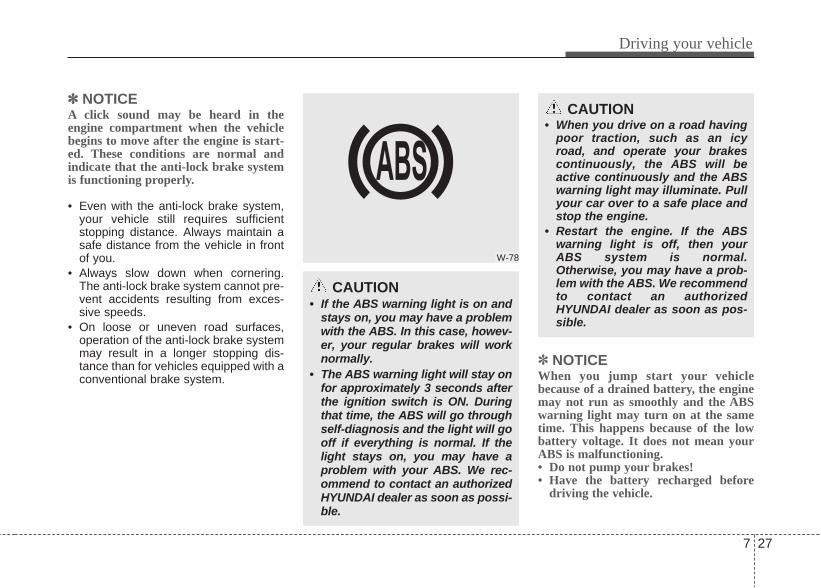
✽✽ NOTICEA click sound may be heard in theengine compartment when the vehiclebegins to move after the engine is start-ed. These conditions are normal andindicate that the anti-lock brake systemis functioning properly.
• Even with the anti-lock brake system,your vehicle still requires sufficientstopping distance. Always maintain asafe distance from the vehicle in frontof you.
• Always slow down when cornering.The anti-lock brake system cannot pre-vent accidents resulting from exces-sive speeds.
• On loose or uneven road surfaces,operation of the anti-lock brake systemmay result in a longer stopping dis-tance than for vehicles equipped with aconventional brake system.
✽ NOTICEWhen you jump start your vehiclebecause of a drained battery, the enginemay not run as smoothly and the ABSwarning light may turn on at the sametime. This happens because of the lowbattery voltage. It does not mean yourABS is malfunctioning.• Do not pump your brakes!• Have the battery recharged before
driving the vehicle.
W-78
CAUTION• If the ABS warning light is on and
stays on, you may have a problemwith the ABS. In this case, howev-er, your regular brakes will worknormally.
• The ABS warning light will stay onfor approximately 3 seconds afterthe ignition switch is ON. Duringthat time, the ABS will go throughself-diagnosis and the light will gooff if everything is normal. If thelight stays on, you may have aproblem with your ABS. We rec-ommend to contact an authorizedHYUNDAI dealer as soon as possi-ble.
CAUTION• When you drive on a road having
poor traction, such as an icyroad, and operate your brakescontinuously, the ABS will beactive continuously and the ABSwarning light may illuminate. Pullyour car over to a safe place andstop the engine.
• Restart the engine. If the ABSwarning light is off, then yourABS system is normal.Otherwise, you may have a prob-lem with the ABS. We recommendto contact an authorizedHYUNDAI dealer as soon as pos-sible.
Driving your vehicle
277

Good braking practices • After parking the vehicle, check to besure the parking brake is not engagedand that the parking brake indicatorlight is out before driving away.
• Driving through water may get thebrakes wet. They can also get wetwhen the car is washed. Wet brakescan be dangerous! Your car will notstop as quickly if the brakes are wet.Wet brakes may cause the car to pullto one side. To dry the brakes, apply the brakeslightly until the braking action returns tonormal, taking care to keep the carunder control at all times. If the brakingaction does not return to normal, stopas soon as it is safe to do so and callfor assistance. We recommend to con-tact an authorized HYUNDAI dealer.
• Don't coast down hills with the car outof gear. This is extremely hazardous.Keep the car in gear at all times, usethe brakes to slow down, then shift to alower gear so that engine braking willhelp you maintain a safe speed.
• Don't "ride" the brake pedal. Restingyour foot on the brake pedal while driv-ing can be dangerous because it canresult in the brakes overheating andlosing their effectiveness. It alsoincreases the wear of the brake com-ponents.
• If a tire goes flat while you are driving,apply the brakes gently and keep thecar pointed straight ahead while youslow down. When you are movingslowly enough for it to be safe to do so,pull off the road and stop in a safeplace.
• If your car is equipped with an auto-matic transaxle, don't let your carcreep forward. To avoid creeping for-ward, keep your foot firmly on thebrake pedal when the car is stopped.
• Use caution when parking on a hill.Firmly engage the parking brake andplace the shift lever in P. If your car isfacing downhill, turn the front wheelsinto the curb to help keep the car fromrolling. If your car is facing uphill, turnthe front wheels away from the curb tohelp keep the car from rolling. If thereis no curb or if it is required by otherconditions to keep the car from rolling,block the wheels.
WARNING• Whenever leaving vehicle or
parking, always set the parkingbrake as far as possible and fullyengage the vehicle's transaxleinto the park position. Vehiclesnot fully engaged in park with theparking brake set are at risk formoving inadvertently and injur-ing yourself or others.
• All vehicles should always havethe parking brake fully engagedwhen parking to avoid inadver-tent movement of the car whichcan injure occupants or pedestri-ans.
7 28
Driving your vehicle

• Under some conditions your parkingbrake can freeze in the engaged posi-tion. This is most likely to happen whenthere is an accumulation of snow or icearound or near the rear brakes or if thebrakes are wet. If there is a risk thatthe parking brake may freeze, apply itonly temporarily while you put the shiftlever in P and block the rear wheels sothe car cannot roll. Then release theparking brake.
• Do not hold the vehicle on the upgradewith the accelerator pedal. This cancause the transaxle to overheat.Always use the brake pedal or parkingbrake.
Driving your vehicle
297

Your vehicle's fuel economy dependsmainly on your style of driving, where youdrive and when you drive.Each of these factors affects how manymiles (kilometers) you can get from a gal-lon (liter) of fuel. To operate your vehicleas economically as possible, use the fol-lowing driving suggestions to help savemoney in both fuel and repairs:• Drive smoothly. Accelerate at a moder-
ate rate. Don't make "jack-rabbit" startsor full-throttle shifts and maintain asteady cruising speed. Don't racebetween stoplights. Try to adjust yourspeed to that of the other traffic so youdon't have to change speeds unneces-sarily. Avoid heavy traffic wheneverpossible. Always maintain a safe dis-tance from other vehicles so you canavoid unnecessary braking. This alsoreduces brake wear.
• Drive at a moderate speed. The fasteryou drive, the more fuel your car uses.Driving at a moderate speed, especial-ly on the highway, is one of the mosteffective ways to reduce fuel consump-tion.
• Don't "ride" the brake pedal. This canincrease fuel consumption and alsoincrease wear on these components.In addition, driving with your foot rest-ing on the brake pedal may cause thebrakes to overheat, which reducestheir effectiveness and may lead tomore serious consequences.
• Take care of your tires. Keep theminflated to the recommended pressure.Incorrect inflation, either too much ortoo little, results in unnecessary tirewear. Check the tire pressures at leastonce a month.
• Be sure that the wheels are alignedcorrectly. Improper alignment canresult from hitting curbs or driving toofast over irregular surfaces. Poor align-ment causes faster tire wear and mayalso result in other problems as well asgreater fuel consumption.
• Keep your car in good condition. Forbetter fuel economy and reducedmaintenance costs, maintain your carin accordance with the maintenanceschedule in section 7. If you drive yourcar in severe conditions, more frequentmaintenance is required (see section 7for details).
• Keep your car clean. For maximumservice, your vehicle should be keptclean and free of corrosive materials. Itis especially important that mud, dirt,ice, etc. not be allowed to accumulateon the underside of the car. This extraweight can result in increased fuel con-sumption and also contribute to corro-sion.
• Travel lightly. Don't carry unnecessaryweight in your car. Weight reduces fueleconomy.
• Don't let the engine idle longer thannecessary. If you are waiting (and notin traffic), turn off your engine andrestart only when you're ready to go.
ECONOMICAL OPERATION
7 30
Driving your vehicle

• Remember, your vehicle does notrequire extended warm-up. After theengine has started, allow the engine torun for 10 to 20 seconds prior to plac-ing the vehicle in gear. In very coldweather, however, give your engine aslightly longer warm-up period.
• Don't "lug" or "over-rev" the engine.Lugging is driving too slowly in too higha gear resulting in the engine bucking.If this happens, shift to a lower gear.Over-revving is racing the enginebeyond its safe limit. This can beavoided by shifting at the recommend-ed speeds.
• Use your air conditioning sparingly.The air conditioning system is operat-ed by engine power so your fuel econ-omy is reduced when you use it.
• Open windows at high speeds canreduce fuel economy.
• Fuel economy is less in crosswindsand headwinds. To help offset some ofthis loss, slow down when driving inthese conditions.
Keeping a vehicle in good operating con-dition is important both for economy andsafety. Therefore, we recommend tohave an authorized HYUNDAI dealerperform scheduled inspections andmaintenance.
WARNING - Engine offduring motion
Never turn the engine off to coastdown hills or anytime the vehicle isin motion. The power steering andpower brakes will not functionproperly without the engine run-ning. Instead, keep the engine onand downshift to an appropriategear for engine braking effect. Inaddition, turning off the ignitionwhile driving could engage thesteering wheel lock resulting inloss of vehicle steering whichcould cause serious injury ordeath.
Driving your vehicle
317

Hazardous driving conditions When hazardous driving conditions areencountered such as water, snow, ice,mud, sand, or similar hazards, followthese suggestions:• Drive cautiously and allow extra dis-
tance for braking.• Avoid sudden movements in braking or
steering.• When braking with non-ABS brakes
pump the brake pedal with a light up-and-down motion until the vehicle isstopped.
• If stalled in snow, mud, or sand, usesecond gear. Accelerate slowly toavoid spinning the drive wheels.
• Use sand, rock salt, tire chains, orother non-slip material under the drivewheels to provide traction when stalledin ice, snow, or mud.
Rocking the vehicle If it is necessary to rock the vehicle tofree it from snow, sand, or mud, first turnthe steering wheel right and left to clearthe area around your front wheels. Then,shift back and forth between 1st (First)and R (Reverse) in vehicles equippedwith a manual transaxle or R (Reverse)and any forward gear in vehiclesequipped with an automatic transaxle.Do not race the engine, and spin thewheels as little as possible. If you are stillstuck after a few tries, have the vehiclepulled out by a tow vehicle to avoidengine overheating and possible dam-age to the transaxle.
SPECIAL DRIVING CONDITIONS
1JBB3302
WARNING - ABSDo not pump the brake pedal on avehicle equipped with ABS.
WARNING - DownshiftingDownshifting with an automatictransaxle, while driving on slipperysurfaces can cause an accident.The sudden change in tire speedcould cause the tires to skid. Becareful when downshifting on slip-pery surfaces.
CAUTIONProlonged rocking may causeengine over-heating, transaxledamage or failure, and tire damage.
7 32
Driving your vehicle

✽✽ NOTICEThe ESP system should be turned OFFprior to rocking the vehicle. Smooth cornering
Avoid braking or gear changing in cor-ners, especially when roads are wet.Ideally, corners should always be takenunder gentle acceleration. If you followthese suggestions, tire wear will be heldto a minimum.
Driving at night Because night driving presents morehazards than driving in the daylight, hereare some important tips to remember:• Slow down and keep more distance
between you and other vehicles, as itmay be more difficult to see at night,especially in areas where there maynot be any street lights.
WARNING - Spinning tiresDo not spin the wheels, especiallyat speeds more than 56 km/h (35mph). Spinning the wheels at highspeeds when the vehicle is station-ary could cause a tire to overheatwhich could result in tire damagethat may injure bystanders.
OMC035004
WARNINGIf your vehicle becomes stuck insnow, mud, sand, etc., then youmay attempt to rock the vehicle freeby moving it forward and back-ward. Do not attempt this proce-dure if people or objects are any-where near the vehicle. During therocking operation the vehicle maysuddenly move forward of back-ward as it becomes unstuck, caus-ing injury or damage to nearby peo-ple or objects.
OBH058035L/H
Driving your vehicle
337

• Adjust your mirrors to reduce the glarefrom other driver's headlights.
• Keep your headlights clean and prop-erly aimed on vehicles not equippedwith the automatic headlight aimingfeature. Dirty or improperly aimedheadlights will make it much more diffi-cult to see at night.
• Avoid staring directly at the headlightsof oncoming vehicles. You could betemporarily blinded, and it will takeseveral seconds for your eyes to read-just to the darkness.
Driving in the rain Rain and wet roads can make drivingdangerous, especially if you’re not pre-pared for the slick pavement. Here are afew things to consider when driving in therain:• A heavy rainfall will make it harder to
see and will increase the distanceneeded to stop your vehicle, so slowdown.
• Keep your windshield wiping equip-ment in good shape. Replace yourwindshield wiper blades when theyshow signs of streaking or missingareas on the windshield.
• If your tires are not in good condition,making a quick stop on wet pavementcan cause a skid and possibly lead toan accident. Be sure your tires are ingood shape.
• Turn on your headlights to make it eas-ier for others to see you.
• Driving too fast through large puddlescan affect your brakes. If you must gothrough puddles, try to drive throughthem slowly.
• If you believe you may have gottenyour brakes wet, apply them lightlywhile driving until normal braking oper-ation returns.
Driving in flooded areas Avoid driving through flooded areasunless you are sure the water is no high-er than the bottom of the wheel hub.Drive through any water slowly. Allowadequate stopping distance becausebrake performance may be affected.After driving through water, dry thebrakes by gently applying them severaltimes while the vehicle is moving slowly.
7 34
Driving your vehicle

Highway drivingTiresAdjust the tire inflation pressures tospecification. Low tire inflation pressureswill result in overheating and possiblefailure of the tires.Avoid using worn or damaged tires whichmay result in reduced traction or tire fail-ure.
✽✽ NOTICENever exceed the maximum tire inflationpressure shown on the tires.
Fuel, engine coolant and engine oilHigh speed travel consumes more fuelthan urban motoring. Do not forget tocheck both engine coolant and engineoil.
Drive beltA loose or damaged drive belt may resultin overheating of the engine.
WARNING• Underinflated or overinflated
tires can cause poor handling,loss of vehicle control, and sud-den tire failure leading to acci-dents, injuries, and even death.Always check tires for properinflation before driving. For prop-er tire pressures, refer to “Tiresand wheels” in section 8.
• Driving on tires with no or insuffi-cient tread is dangerous. Worn-out tires can result in loss ofvehicle control, collisions, injury,and even death. Worn-out tiresshould be replaced as soon aspossible and should never beused for driving. Always checkthe tire tread before driving yourcar. For further information andtread limits, refer to “Tires andwheels” in section 7.
OMG015008
Driving your vehicle
357

Driving your vehicle
367
More severe weather conditions of winterresult in greater wear and other prob-lems. To minimize winter driving prob-lem, you should follow these sugges-tions:
Snowy or icy conditionsTo drive your vehicle in deep snow, itmay be necessary to use snow tires or toinstall tire chains on your tires. If snowtires are needed, it is necessary to selecttires equivalent in size and type of theoriginal equipment tires. Failure to do somay adversely affect the safety and han-dling of your car. Furthermore, speeding,rapid acceleration, sudden brake appli-cations, and sharp turns are potentiallyvery hazardous practices.During deceleration, use engine brakingto the fullest extent. Sudden brake appli-cations on snowy or icy roads may causeskids to occur. You need to keep suffi-cient distance between the vehicle inoperation in front and your vehicle. Also,apply the brake gently. It should be notedthat installing tire chains on the tire willprovide a greater driving force, but willnot prevent side skids.
✽ NOTICETire chains are not legal in all countries.Check country laws before fitting tirechains.
Snow tires If you mount snow tires on your vehicle,make sure they are radial tires of thesame size and load range as the originaltires. Mount snow tires on all four wheelsto balance your vehicle’s handling in allweather conditions. Keep in mind thatthe traction provided by snow tires on dryroads may not be as high as your vehi-cle's original equipment tires. You shoulddrive cautiously even when the roads areclear. Check with the tire dealer for max-imum speed recommendations.
Do not install studded tires without firstchecking local, state and municipal regu-lations for possible restrictions againsttheir use.
WINTER DRIVING
WARNING - Snow tire sizeSnow tires should be equivalent insize and type to the vehicle's stan-dard tires. Otherwise, the safetyand handling of your vehicle maybe adversely affected.
1JBB3305
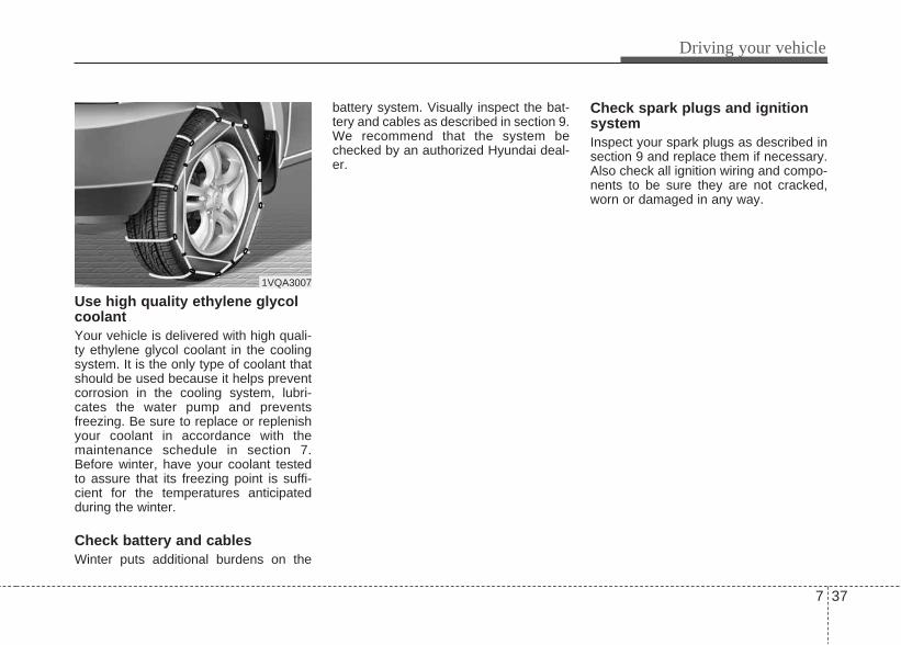
7 37
Driving your vehicle
Use high quality ethylene glycolcoolantYour vehicle is delivered with high quali-ty ethylene glycol coolant in the coolingsystem. It is the only type of coolant thatshould be used because it helps preventcorrosion in the cooling system, lubri-cates the water pump and preventsfreezing. Be sure to replace or replenishyour coolant in accordance with themaintenance schedule in section 7.Before winter, have your coolant testedto assure that its freezing point is suffi-cient for the temperatures anticipatedduring the winter.
Check battery and cablesWinter puts additional burdens on the
battery system. Visually inspect the bat-tery and cables as described in section 9.We recommend that the system bechecked by an authorized Hyundai deal-er.
Check spark plugs and ignitionsystemInspect your spark plugs as described insection 9 and replace them if necessary.Also check all ignition wiring and compo-nents to be sure they are not cracked,worn or damaged in any way.
1VQA3007

To keep locks from freezingTo keep the locks from freezing, squirt anapproved de-icer fluid or glycerine intothe key opening. If a lock is covered withice, squirt it with an approved de-icingfluid to remove the ice. If the lock isfrozen internally, you may be able tothaw it out by using a heated key. Handlethe heated key with care to avoid injury.
Use approved window washeranti-freeze in systemTo keep the water in the window washersystem from freezing, add an approvedwindow washer anti-freeze solution inaccordance with instructions on the con-tainer. Window washer anti-freeze isavailable from an authorized HYUNDAIdealer and most auto parts outlets. Donot use engine coolant or other types ofanti-freeze as these may damage thepaint finish.
Don't let your parking brakefreezeUnder some conditions your parkingbrake can freeze in the engaged posi-tion. This is most likely to happen whenthere is an accumulation of snow or icearound or near the rear brakes or if thebrakes are wet. If there is a risk the park-ing brake may freeze, apply it only tem-porarily while you put the shift lever in P(automatic transaxle) or in first or reversegear (manual transaxle) and block therear wheels so the vehicle cannot roll.Then release the parking brake.
Don't let ice and snow accumu-late underneathUnder some conditions, snow and icecan build up under the fenders and inter-fere with the steering. When driving insevere winter conditions where this mayhappen, you should periodically checkunderneath the car to be sure the move-ment of the front wheels and the steeringcomponents is not obstructed.
Carry emergency equipmentDepending on the severity of the weath-er where you drive your car, you shouldcarry appropriate emergency equipment.Some of the items you may want to carryinclude tire chains, tow straps or chains,flashlight, emergency flares, sand, ashovel, jumper cables, a windowscraper, gloves, ground cloth, coveralls,a blanket, etc.
7 38
Driving your vehicle

This section will guide you in the properloading of your vehicle, to keep yourloaded vehicle weight within its designrating capability. Properly loading yourvehicle will provide maximum return ofthe vehicle design performance. Beforeloading your vehicle, familiarize yourselfwith the following terms for determiningyour vehicle's weight ratings, from thevehicle's specifications and the certifica-tion label:
Base curb weight This is the weight of the vehicle includinga full tank of fuel and all standard equip-ment. It does not include passengers,cargo, or optional equipment.
Vehicle curb weightThis is the weight of your new vehiclewhen you picked it up from your dealerplus any aftermarket equipment.
Cargo weightThis figure includes all weight added tothe Base Curb Weight, including cargoand optional equipment.
GAW (Gross axle weight)This is the total weight placed on eachaxle (front and rear) - including vehiclecurb weight and all payload.
GAWR (Gross axle weight rating)This is the maximum allowable weightthat can be carried by a single axle (frontor rear). These numbers are shown onthe certification label. The total load on each axle must neverexceed its GAWR.
GVW (Gross vehicle weight)This is the Base Curb Weight plus actualCargo Weight plus passengers.
GVWR (Gross vehicle weight rat-ing)This is the maximum allowable weight ofthe fully loaded vehicle (including alloptions, equipment, passengers andcargo). The GVWR is shown on the cer-tification label located on the driver’s (orfront passenger’s) door sill.
Overloading
VEHICLE WEIGHT
WARNING - Vehicle weightThe gross axle weight rating(GAWR) and the gross vehicleweight rating (GVWR) for your vehi-cle are on the certification labelattached to the driver's (or frontpassenger’s) door. Exceedingthese ratings can cause an acci-dent or vehicle damage. You cancalculate the weight of your load byweighing the items (and people)before putting them in the vehicle.Be careful not to overload yourvehicle.
Driving your vehicle
397


Road warning / 8-2In case of an emergency while driving / 8-3If the engine does not start / 8-4Emergency starting / 8-5If the engine overheats / 8-7If you have a flat tire / 8-8Towing / 8-14
8What to do in an emergency

What to do in an emergency
28
ROAD WARNING
Hazard warning flasher The hazard warning flasher serves as awarning to other drivers to exerciseextreme caution when approaching,overtaking, or passing your vehicle.
It should be used whenever emergencyrepairs are being made or when the vehi-cle is stopped near the edge of a road-way.Depress the flasher switch with the igni-tion switch in any position. The flasherswitch is located in the center consoleswitch panel. All turn signal lights willflash simultaneously.
• The hazard warning flasher operateswhether your vehicle is running or not.
• The turn signals do not work when thehazard flasher is on.
• Care must be taken when using thehazard warning flasher while the vehi-cle is being towed.
ORB040045

8 3
What to do in an emergency
IN CASE OF AN EMERGENCY WHILE DRIVINGIf the engine stalls at a crossroador crossing• If the engine stalls at a crossroad or
crossing, set the shift lever in the N(Neutral) position and then push thevehicle to a safe place.
• If your vehicle has a manual transaxlenot equipped with a ignition lockswitch, the vehicle can move forwardby shifting to the 2(second) or 3(third)gear and then turning the starter with-out depressing the clutch pedal.
If you have a flat tire while driv-ingIf a tire goes flat while you are driving:1.Take your foot off the accelerator
pedal and let the car slow down whiledriving straight ahead. Do not applythe brakes immediately or attempt topull off the road as this may cause aloss of control. When the car hasslowed to such a speed that it is safe todo so, brake carefully and pull off theroad. Drive off the road as far as pos-sible and park on firm, level ground. Ifyou are on a divided highway, do notpark in the median area between thetwo traffic lanes.
2.When the vehicle is stopped, turn onyour emergency hazard flashers, setthe parking brake and put the transaxlein P (automatic transaxle) or reverse(manual transaxle).
3.Have all passengers get out of the car.Be sure they all get out on the side ofthe car that is away from traffic.
4.When changing a flat tire, follow theinstruction provided later in this sec-tion.
If engine stalls while driving1. Reduce your speed gradually, keeping
a straight line. Move cautiously off theroad to a safe place.
2. Turn on your emergency flashers.3. Try to start the engine again. If your
vehicle will not start, we recommendto contact an authorized HYUNDAIdealer or seek other qualified assis-tance.

What to do in an emergency
48
IF THE ENGINE DOES NOT STARTIf engine doesn't turn over orturns over slowly1. If your vehicle has an automatic
transaxle, be sure the shift lever is in N(Neutral) or P (Park) and the emer-gency brake is set.
2. Check the battery connections to besure they are clean and tight.
3. Turn on the interior light. If the lightdims or goes out when you operatethe starter, the battery is discharged.
4. Check the starter connections to besure they are securely tightened.
5. Do not push or pull the vehicle to startit. See instructions for "Jump starting".
If engine turns over normally butdoes not start1. Check fuel level.2. With the ignition switch in the LOCK
/OFF position, check all connectors atthe ignition coils and spark plugs.Reconnect any that may be discon-nected or loose.
3. Check the fuel line in the engine com-partment.
4. If the engine still does not start, werecommend to call an authorizedHYUNDAI dealer or seek other quali-fied assistance.
WARNINGIf the engine will not start, do notpush or pull the vehicle to start it.This could result in a collision orcause other damage. In addition,push or pull starting may cause thecatalytic converter to be over-loaded and create a fire hazard.

8 5
What to do in an emergency
EMERGENCY STARTING
Connect cables in numerical order anddisconnect in reverse order.
Jump starting Jump starting can be dangerous if doneincorrectly. Therefore, to avoid harm toyourself or damage to your vehicle orbattery, follow the jump starting proce-dures. If in doubt, we strongly recom-mend that you have a competent techni-cian or towing service jump start yourvehicle.
CAUTIONUse only a 12-volt jumper system.You can damage a 12-volt startingmotor, ignition system, and otherelectrical parts beyond repair byuse of a 24-volt power supply (eithertwo 12-volt batteries in series or a24-volt motor generator set).
WARNING - Battery• Keep all flames or sparks away
from the battery. The battery pro-duces hydrogen gas which mayexplode if exposed to flame orsparks. If these instructions are not fol-lowed exactly, serious personalinjury and damage to the vehiclemay occur! If you are not surehow to follow this procedure,seek qualified assistance.Automobile batteries contain sul-furic acid. This is poisonous andhighly corrosive. When jumpstarting, wear protective glassesand be careful not to get acid onyourself, your clothing or on thecar.
• Do not attempt to jump start thevehicle if the discharged batteryis frozen or if the electrolyte levelis low; the battery may rupture orexplode.
WARNING - BatteryNever attempt to check the elec-trolyte level of the battery as thismay cause the battery to rupture orexplode causing serious injury.
1VQA4001

What to do in an emergency
68
Jump starting procedure 1. Make sure the booster battery is 12-
volt and that its negative terminal isgrounded.
2. If the booster battery is in anothervehicle, do not allow the vehicles totouch.
3. Turn off all unnecessary electricalloads.
4. Connect the jumper cables in theexact sequence shown in the illustra-tion. First connect one end of a jumpercable to the positive terminal of thejump start connector (1), then connectthe other end to the positive terminalon the booster battery (2). Proceed to connect one end of theother jumper cable to the negative ter-minal of the booster battery (3), thenthe other end to the negative terminalof the jump start connector (4). Do notconnect it to or near any part thatmoves when the engine is cranked.
Do not allow the jumper cables to con-tact anything except the correct batteryterminals or the correct ground. Do notlean over the battery when makingconnections.
5. Start the engine of the vehicle with thebooster battery and let it run at 2,000rpm, then start the engine of the vehi-cle with the discharged battery.
If the cause of your battery discharging isnot apparent, you should have your vehi-cle checked. We recommend to have itchecked by an authorized HYUNDAIdealer.
Push-starting Your manual transaxle-equipped vehicleshould not be push-started because itmight damage the emission control sys-tem.Vehicles equipped with automatictransaxle cannot be push-started. Follow the directions in this section forjump-starting.
CAUTION - Battery cablesDo not connect the jumper cablefrom the negative terminal of thebooster battery to the negative ter-minal of the discharged battery.This can cause the discharged bat-tery to overheat and crack, releas-ing battery acid.
WARNINGNever tow a vehicle to start itbecause the sudden surge forwardwhen the engine starts could causea collision with the tow vehicle.

8 7
What to do in an emergency
IF THE ENGINE OVERHEATSIf your temperature gauge indicatesoverheating, you experience a loss ofpower, or hear loud pinging or knocking,the engine is probably too hot. If this hap-pens, you should:
1. Pull off the road and stop as soon as itis safe to do so.
2. Place the shift lever in P (automatictransaxle) or neutral (manualtransaxle) and set the parking brake. Ifthe air conditioning is on, turn it off.
3. If engine coolant is running out underthe car or steam is coming out fromthe hood, stop the engine. Do notopen the hood until the coolant hasstopped running or the steaming hasstopped. If there is no visible loss ofengine coolant and no steam, leavethe engine running and check to besure the engine cooling fan is operat-ing. If the fan is not running, turn theengine off.
4. Check to see if the water pump drivebelt is missing. If it is not missing,check to see that it is tight. If the drivebelt seems to be satisfactory, checkfor coolant leaking from the radiator,hoses or under the car. (If the air con-ditioning had been in use, it is normalfor cold water to be draining from itwhen you stop).
5. If the water pump drive belt is brokenor engine coolant is leaking out, stopthe engine immediately and call forassistance. We recommend to contactan authorized HYUNDAI dealer.
6. If you cannot find the cause of theoverheating, wait until the engine tem-perature has returned to normal. Then,if coolant has been lost, carefully addcoolant to the reservoir to bring thefluid level in the reservoir up to thehalfway mark.
7.Proceed with caution, keeping alert forfurther signs of overheating. If over-heating happens again, call for assis-tance. We recommend to contact anauthorized HYUNDAI dealer.
WARNINGWhile the engine is running, keephair, hands and clothing away frommoving parts such as the fan anddrive belts to prevent injury.
WARNINGDo not remove the radiator capwhen the engine is hot. This canallow coolant to be blown out of theopening and cause serious burns.
CAUTIONSerious loss of coolant indicatesthere is a leak in the cooling systemand this should be checked as soonas possible. We recommend to haveit checked by an authorized Hyundaidealer.

What to do in an emergency
88
(Continued)• Be sure to use the correct
front and rear jacking posi-tions on the vehicle; neveruse the bumpers or any otherpart of the vehicle for jacksupport.
• The vehicle can easily roll offthe jack causing seriousinjury or death. No personshould place any portion oftheir body under a vehiclethat is supported only by ajack; use vehicle supportstands.
• Do not start or run the enginewhile the vehicle is on thejack.
• Do not allow anyone toremain in the vehicle while itis on the jack.
• Make sure any children pres-ent are in a secure place awayfrom the road and from thevehicle to be raised with thejack.
IF YOU HAVE A FLAT TIRE
Jack and toolsThe jack, jack handle, and wheel lugnut wrench are stored in the luggagecompartment. Pull up the luggagebox cover to reach this equipment.(1) Jack(2) Jack handle(3) Wheel lug nut wrench
Jacking instructions The jack is provided for emergencytire changing only.To prevent the jack from “rattling”while the vehicle is in motion, store itproperly.Follow jacking instructions to reducethe possibility of personal injury.
WARNING - Changing tires• Never attempt vehicle repairs
in the traffic lanes of a publicroad or highway.
• Always move the vehicle com-pletely off the road and ontothe shoulder before trying tochange a tire. The jack shouldbe used on level firm ground.If you cannot find a firm, levelplace off the road, call a tow-ing service company forassistance.
(Continued)
ORB060001

8 9
What to do in an emergency
Removing and storing the sparetire Turn the tire hold-down wing boltcounterclockwise.Store the tire in the reverse order ofremoval.To prevent the spare tire and toolsfrom “rattling” while the vehicle is inmotion, store them properly.
Changing tires1. Park on a level surface and apply
the parking brake firmly.2. Shift the shift lever into R
(Reverse) with manual transaxleor P (Park) with automatictransaxle.
3. Activate the hazard warning flash-er.
4. Remove the wheel lug nutwrench, jack, jack handle, andspare tire from the vehicle.
5. Block both the front and rear of thewheel that is diagonally oppositethe jack position.
ORBC060002 OBH068002L/H 1JBA6504

What to do in an emergency
108
6. Loosen the wheel lug nuts coun-terclockwise one turn each, but donot remove any nut until the tirehas been raised off the ground.
7. Place the jack at the front or rearjacking position closest to the tireyou are changing. Place the jackat the designated locations underthe frame. The jacking positionsare plates welded to the framewith two tabs and a raised dot toindex with the jack.
WARNING - Changing a tire• To prevent vehicle movement
while changing a tire, alwaysset the parking brake fully,and always block the wheeldiagonally opposite the wheelbeing changed.
• We recommend that thewheels of the vehicle beblocked, and that no personremain in the vehicle that isbeing jacked.
ORBC060003 1JB6025

8 11
What to do in an emergency
8. Insert the jack handle into the jackand turn it clockwise, raising thevehicle until the tire just clears theground. This measurement isapproximately 30 mm (1.2 in).Before removing the wheel lugnuts, make sure the vehicle is sta-ble and that there is no chance formovement or slippage.
9. Loosen the wheel nuts andremove them with your fingers.Slide the wheel off the studs andlay it flat so it cannot roll away. Toput the wheel on the hub, pick upthe spare tire, line up the holeswith the studs and slide the wheelonto them. If this is difficult, tip thewheel slightly and get the top holein the wheel lined up with the topstud. Then jiggle the wheel backand forth until the wheel can beslid over the other studs.
WARNING - Jack locationTo reduce the possibility ofinjury, be sure to use only thejack provided with the vehicleand in the correct jack position;never use any other part of thevehicle for jack support.
ORBC060004

What to do in an emergency
128
10. To reinstall the wheel, hold it onthe studs, put the wheel nuts onthe studs and tighten them fingertight. The nuts should beinstalled with their tapered smalldiameter ends directed inward.Jiggle the tire to be sure it iscompletely seated, then tightenthe nuts as much as possiblewith your fingers again.
11. Lower the car to the ground byturning the wheel nut wrenchcounterclockwise. Then position the wrench as shown
in the drawing and tighten the wheelnuts. Be sure the socket is seatedcompletely over the nut. Do notstand on the wrench handle or usean extension pipe over the wrenchhandle. Go around the wheel tight-ening every other nut until they areall tight. Then double-check each nutfor tightness. After changing wheels,have the wheel nuts tightened totheir proper torque as soon as possi-ble. We recommend to have it doneby an authorized HYUNDAI dealer.
Wheel nut tightening torque:Steel wheel & aluminum alloy wheel:9~11 kg·m (65~79 lb·ft)
WARNINGWheels may have sharp edges.Handle them carefully to avoidpossible severe injury. Beforeputting the wheel into place, besure that there is nothing on thehub or wheel (such as mud, tar,gravel, etc.) that interferes withthe wheel from fitting solidlyagainst the hub. If there is, remove it. If there isnot good contact on the mount-ing surface between the wheeland hub, the wheel nuts couldcome loose and cause the lossof a wheel. Loss of a wheel mayresult in loss of control of thevehicle. This may cause seriousinjury or death.
ORBC060005

8 13
What to do in an emergency
If you have a tire gauge, remove thevalve cap and check the air pres-sure. If the pressure is lower thanrecommended, drive slowly to thenearest service station and inflate tothe correct pressure. If it is too high,adjust it until it is correct. Alwaysreinstall the valve cap after checkingor adjusting tire pressure. If the capis not replaced, air may leak from thetire. If you lose a valve cap, buyanother and install it as soon as pos-sible.After you have changed wheels,always secure the flat tire in its placeand return the jack and tools to theirproper storage locations.
To prevent the jack, jack handle,wheel lug nut wrench and spare tirefrom rattling while the vehicle is inmotion, store them properly.
CAUTIONYour vehicle has metric threadson the wheel studs and nuts.Make certain during wheelremoval that the same nuts thatwere removed are reinstalled -or, if replaced, that nuts withmetric threads and the samechamfer configuration are used.Installation of a non-metricthread nut on a metric stud orvice-versa will not secure thewheel to the hub properly andwill damage the stud so that itmust be replaced. Note that most lug nuts do nothave metric threads. Be sure touse extreme care in checkingfor thread style before installingaftermarket lug nuts or wheels.If in doubt, we recommend toconsult an authorized HYUNDAIdealer.
WARNING - Wheel studsIf the studs are damaged, theymay lose their ability to retainthe wheel. This could lead to theloss of the wheel and a collisionresulting in serious injuries.
WARNING - Inadequatespare tire pressure
Check the inflation pressures assoon as possible after installingthe spare tire. Adjust it to thespecified pressure, if necessary.Refer to “Tires and wheels” sec-tion 8.

What to do in an emergency
148
TOWING
Towing serviceIf emergency towing is necessary, werecommend having it done by an author-ized HYUNDAI dealer or a commercialtow-truck service. Proper lifting and tow-ing procedures are necessary to preventdamage to the vehicle. The use of wheeldollies or flatbed is recommended.
It is acceptable to tow the vehicle withthe rear wheels on the ground (withoutdollies) and the front wheels off theground.If any of the loaded wheels or suspen-sion components are damaged or thevehicle is being towed with the frontwheels on the ground, use a towing dollyunder the front wheels.When being towed by a commercial towtruck and wheel dollies are not used, thefront of the vehicle should always be lift-ed, not the rear.
HXD02
HXD03
CAUTION• Do not tow the vehicle with the
front wheels on the ground asthis may cause damage to thevehicle.
• Do not tow with sling-type equip-ment. Use wheel lift or flatbedequipment.
OMC045012
A
B
C dolly

8 15
What to do in an emergency
When towing your vehicle in an emer-gency without wheel dollies : 1. Set the ignition switch in the ACC
position.2. Place the shift lever in N (Neutral).3. Release the parking brake.
Removable towing hook (front, if equipped)1. Open the trunk, and remove the tow-
ing hook from the tool case.2. Remove the hole cover pressing the
lower part of the cover on the frontbumper.
3. Install the towing hook by turning itclockwise into the hole until it is fullysecured.
4. Remove the towing hook and installthe cover after use.
Emergency towingIf towing is necessary, we recommendyou to have it done by an authorizedHYUNDAI dealer or a commercial towtruck service.
CAUTIONFailure to place the shift lever in N(Neutral) may cause internal dam-age to the transaxle.
ORB060006
■ Front
ORB060007
ORBC060008
■ Front
■ Rear
What to do in an emergency
168
If towing service is not available in anemergency, your vehicle may be tem-porarily towed using a cable or chainsecured to the emergency towing hookunder the front/rear of the vehicle. Useextreme caution when towing the vehi-cle. A driver must be in the vehicle tosteer it and operate the brakes.Towing in this manner may be done onlyon hard-surfaced roads for a short dis-tance and at low speeds. Also, thewheels, axles, power train, steering andbrakes must all be in good condition.• Do not use the tow hooks to pull a
vehicle out of mud, sand or other con-ditions from which the vehicle cannotbe driven out under its own power.
• Avoid towing a vehicle heavier than thevehicle doing the towing.
• The drivers of both vehicles shouldcommunicate with each other fre-quently.
• Before emergency towing, check thatthe hook is not broken or damaged.
• Fasten the towing cable or chainsecurely to the hook.
• Do not jerk the hook. Apply steady andeven force.
• To avoid damaging the hook, do notpull from the side or at a vertical angle.Always pull straight ahead.
CAUTION• Attach a towing strap to the tow
hook.• Using a portion of the vehicle
other than the tow hooks for tow-ing may damage the body of yourvehicle.
• Use only a cable or chain specifi-cally intended for use in towingvehicles. Securely fasten thecable or chain to the towing hookprovided.
WARNING Use extreme caution when towingthe vehicle. • Avoid sudden starts or erratic
driving maneuvers which wouldplace excessive stress on theemergency towing hook and tow-ing cable or chain. The hook andtowing cable or chain may breakand cause serious injury or dam-age.
• If the disabled vehicle is unableto be moved, do not forcibly con-tinue the towing. Contact anauthorized HYUNDAI dealer or acommercial tow truck service forassistance.
• Tow the vehicle as straight aheadas possible.
• Keep away from the vehicle dur-ing towing.

8 17
What to do in an emergency
• Use a towing strap less than 5 m (16feet) long. Attach a white or red cloth(about 30 cm (12 inches) wide) in themiddle of the strap for easy visibility.
• Drive carefully so that the towing strapis not loosened during towing.
Emergency towing precautions• Place the ignition switch in ACC so the
steering wheel isn’t locked.• Place the transaxle shift lever in N
(Neutral).• Release the parking bake.• Press the brake pedal with more force
than normal since you will havereduced brake performance.
• More steering effort will be requiredbecause the power steering systemwill be disabled.
• If you are driving down a long hill, thebrakes may overheat and brake per-formance will be reduced. Stop oftenand let the brakes cool off.
CAUTION - Automatictransaxle
• If the car is being towed with allfour wheels on the ground, it canbe towed only from the front. Besure that the transaxle is in neu-tral. Be sure the steering isunlocked by placing the ignitionswitch in the ACC position. Adriver must be in the towed vehi-cle to operate the steering andbrakes.
• To avoid serious damage to theautomatic transaxle, limit thevehicle speed to 15 km/h (10 mph)and drive less than 1.5 km (1mile) when towing.
• Before towing, check the auto-matic transaxle fluid leak underyour vehicle. If the automatictransaxle fluid is leaking, aflatbed equipment or towing dollymust be used.
OTD069011


Engine compartment / 9-2Maintenance services / 9-8Owner maintenance / 9-5Scheduled maintenance service / 9-7Explanation of scheduled maintenance items / 9-18Engine oil / 9-21Engine coolant / 9-23Brake/clutch fluid / 9-26Automatic transaxle fluid / 9-27Washer fluid / 9-29Parking brake / 9-29Fuel filter / 9-30Air cleaner / 9-31Climate control air filter / 9-33Wiper blades / 9-35Battery / 9-37Tires and wheels / 9-40Fuses / 9-50Light bulbs / 9-61Appearance care / 9-68
Emission control system / 9-74
9Maintenance

Maintenance
29
ENGINE COMPARTMENT
ORBI071001G/ORBI071001* The actual engine room in the vehicle may differ from the illustration.
1. Engine coolant reservoir...................9-24
2. Windshield washer fluid reservoir.....9-29
3. Radiator cap .....................................9-25
4. Engine oil filler cap ...........................9-19
5. Engine oil dipstick.............................9-21
6. Brake/clutch* fluid reservoir..............9-26
7. Air cleaner ........................................9-31
8. Fuse box...........................................9-50
9. Positive battery terminal ..................9-39
10. Negative battery terminal ..............9-37
11. Automatic transaxle fluid dipstick* .........................................9-27
* : if equipped
■ Gasoline Engine
■ Diesel Engine

9 3
Maintenance
MAINTENANCE SERVICESYou should exercise the utmost care toprevent damage to your vehicle andinjury to yourself whenever performingany maintenance or inspection proce-dures.Inadequate, incomplete or insufficientservicing may result in operational prob-lems with your vehicle that could lead tovehicle damage, an accident, or person-al injury.
Owner’s responsibility
✽ NOTICEMaintenance Service and RecordRetention are the owner's responsibility.
We recommend in general that you haveyour vehicle serviced by an authorizedHYUNDAI dealer.You should retain documents that showproper maintenance has been performedon your vehicle in accordance with thescheduled maintenance service chartsshown on the following pages. You needthis information to establish your compli-ance with the servicing and maintenancerequirements of your vehicle warranties.Detailed warranty information is providedin your Service Passport.Repairs and adjustments required as aresult of improper maintenance or a lackof required maintenance are not coveredwhen your vehicle is covered by warran-ty.
Owner maintenance precautions Improper or incomplete service mayresult in problems. This section givesinstructions only for the maintenanceitems that are easy to perform.
✽ NOTICEImproper owner maintenance duringthe warranty period may affect warran-ty coverage. If you're unsure about anyservicing or maintenance procedure, werecommend that the system be servicedby an authorized HYUNDAI dealer.

Maintenance
49
Engine compartment precautions(Diesel engine)• Follow the safety tips provided below,
when you are checking the engineroom while the engine is running.- Do not touch the injector, injector
wirings, and the engine computerwhile the engine is running.
- Do not remove the injector connectorwhile the engine is running.
- People using pacemakers must notgo near the engine while the engineis starting or running.
WARNING - Maintenancework
• Performing maintenance work ona vehicle can be dangerous. Youcan be seriously injured whileperforming some maintenanceprocedures. If you lack sufficientknowledge and experience or theproper tools and equipment to dothe work, we recommend that thesystem be serviced by an author-ized HYUNDAI dealer.
• Working under the hood with theengine running is dangerous. Itbecomes even more dangerouswhen you wear jewelry or looseclothing. These can becomeentangled in moving parts andresult in injury. Therefore, if youmust run the engine while work-ing under the hood, make certainthat you remove all jewelry (espe-cially rings, bracelets, watches,and necklaces) and all neckties,scarves, and similar loose cloth-ing before getting near theengine or cooling fans.
WARNING - Diesel EngineNever work on injection systemwith engine running or within 30seconds after shutting off engine.High-pressure pump, rail, injectorsand high-pressure pipes are sub-ject to high pressure even after theengine stopped. The fuel jet pro-duced by fuel leaks may cause seri-ous injury, if it touches the body.People using pacemakers shouldnot move than 30cm closer to theECU or wiring harness within theengine room while engine is run-ning, since the high currents in theelectronic engine control systemproduce considerable magneticfields.

9 5
Maintenance
OWNER MAINTENANCE The following lists are vehicle checksand inspections that should be per-formed at the frequencies indicated tohelp ensure safe, dependable operationof your vehicle.If you have any question, we recommendthat you consult an authorized HYUNDAIdealer.These Owner Maintenance Checks aregenerally not covered by warranties andyou may be charged for labor, parts andlubricants used..These Owner Maintenance Checks aregenerally not covered by warranties andyou may be charged for labor, parts andlubricants used.
Owner maintenance schedule When you stop for fuel:• Check the engine oil level.• Check coolant level in coolant reser-
voir.• Check the windshield washer fluid
level.• Look for low or under-inflated tires.
While operating your vehicle:• Note any changes in the sound of the
exhaust or any smell of exhaust fumesin the vehicle.
• Check for vibrations in the steeringwheel. Notice any increased steeringeffort or looseness in the steeringwheel, or change in its straight-aheadposition.
• Notice if your vehicle constantly turnsslightly or “pulls” to one side when trav-eling on smooth, level road.
• When stopping, listen and check forunusual sounds, pulling to one side,increased brake pedal travel or “hard-to-push” brake pedal.
• If any slipping or changes in the oper-ation of your transaxle occurs, checkthe transaxle fluid level.
• Check manual transaxle operation,including clutch operation.
• Check automatic transaxle P (Park)function.
• Check parking brake.• Check for fluid leaks under your vehi-
cle (water dripping from the air condi-tioning system during or after use isnormal).
WARNING Be careful when checking yourengine coolant level when theengine is hot. Scalding hot coolantand steam may blow out underpressure. This could cause burnsor other serious injury.

Maintenance
69
At least monthly:• Check coolant level in the engine
coolant reservoir.• Check the operation of all exterior
lights, including the stoplights, turn sig-nals and hazard warning flashers.
• Check the inflation pressures of alltires including the spare.
At least twice a year • Check radiator, heater and air condi-
tioning hoses for leaks or damage.• Check windshield washer spray and
wiper operation. Clean wiper bladeswith clean cloth dampened with wash-er fluid.
• Check headlight alignment.• Check muffler, exhaust pipes, shields
and clamps.• Check the lap/shoulder belts for wear
and function.• Check for worn tires and loose wheel
lug nuts.
At least once a year:• Clean body and door drain holes.• Lubricate door hinges and checks, and
hood hinges.• Lubricate door and hood locks and
latches.• Lubricate door rubber weatherstrips.• Check the air conditioning system.• Inspect and lubricate automatic
transaxle linkage and controls.• Clean battery and terminals.• Check the brake (and clutch) fluid
level.

9 7
Maintenance
SCHEDULED MAINTENANCE SERVICE Follow Normal Maintenance Schedule ifthe vehicle is usually operated wherenone of the following conditions apply. Ifany of the following conditions apply, fol-low Maintenance Under Severe UsageConditions.• Repeated short distance driving.• Driving in dusty conditions or sandy
areas.• Extensive use of brakes.• Driving in areas where salt or other
corrosive materials are being used.• Driving on rough or muddy roads.• Driving in mountainous areas.• Extended periods of idling or low
speed operation.• Driving for a prolonged period in cold
temperatures and/or extremely humidclimates.
• More than 50% driving in heavy citytraffic during hot weather above 32°C(90°F).
If your vehicle is operated under theabove conditions, you should inspect,replace or refill more frequently than thefollowing Normal Maintenance Schedule.After the periods or distance shown inthe chart, continue to follow the pre-scribed maintenance intervals.

Maintenance
89
G040500APB
NORMAL MAINTENANCE SCHEDULE - DIESEL ENGINE
MAINTENANCE INTERVAL
MAINTENANCE ITEM
Number of months or driving distances, whichever comes firstKm x 1,000 1.5 10 20 30 40 50 60 70 80Months 2 12 24 36 48 60 72 84 96Years - 1 2 3 4 5 6 7 8
ENGINE COMPARTMENTEngine oil & filter *1 - R R R R R R R RAir cleaner filter I R R R R R R R RBattery condition I I I I I I I I IUnder bonnet fluid level I I I I I I I I IVacuum hose (for VGT/ WGT) - I I I I I I I ICranckcase ventilation hose - I I I I I I I IBrake fluid - I I R I I R I IBolt and nuts on chasis and body I I I I I I I I IClutch fluid (if equipped) - I I R I I R I IDrive belts alternator *2 - I I I I I I I REngine Timing Chain - - - - I - - - ITensioner/idler/damper pulley Inspect when replacing the drive belt or timing chainEngine coolant *3 *4 - I I R I I R I IManual transaxle fluid (if required) I I I R I I R I IAutomatic transaxle oil * - I I I I I I I R
I : Inspect, R : Replace (After Inspection, Adjust,Repair,Clean or replace * : If equipped*1 : Check the engine oil and leak every 500 km or before starting a long trip.*2 : Adjust alternator and power steering and air conditioner drive belt(if equipped). Adjust & if necessary correct or repalace.*3 : When adding coolent,use only a qualified coolant additive for your vehicle and never mix hard water in the coolant filled at
the factory.An improper coolant mixture can result in serious malfunction or engine damage.
*4 : For your covinenience, it can be replaced prior to it's interval when you do maintenance of other items.
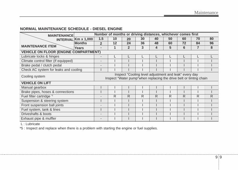
9 9
Maintenance
NORMAL MAINTENANCE SCHEDULE - DIESEL ENGINE
MAINTENANCE INTERVAL
MAINTENANCE ITEM
Number of months or driving distances, whichever comes firstKm x 1,000 1.5 10 20 30 40 50 60 70 80Months 2 12 24 36 48 60 72 84 96Years - 1 2 3 4 5 6 7 8
VEHICLE ON FLOOR (ENGINE COMPARTMENT)Lubricate locks & hinges - L L L L L L L LClimate control filter (If equipped) - I I I I I I I IBrake pedal / clutch pedal - I I I I I I I ICheck AC system for leaks and cooling I I I I I I I I I
Cooling system Inspect "Cooling level adjustment and leak" every dayInspect "Water pump"when replacing the drive belt or timtng chain
VEHICLE ON LIFTManual gearbox I I I I I I I I IBrake pipes, hoses & connections I I I I I I I I IFuel filter cartridge *5 - R R R R R R R RSuspension & steering system I I I I I I I I IFront suspension ball join ts - I I I I I I I IFuel system, tank & lines I I I I I I I I IDriveshafts & boots - I I I I I I I IExhaust pipe & muffler - I I I I I I I IL : Lubricate
*5 : Inspect and replace when there is a problem with starting the engine or fuel supplies.

Maintenance
109
NORMAL MAINTENANCE SCHEDULE - DIESEL ENGINEMAINTENANCE
INTERVAL
MAINTENANCE ITEM
Number of months or driving distances, whichever comes firstKm x 1,000 1.5 10 20 30 40 50 60 70 80Months 2 12 24 36 48 60 72 84 96Years - 1 2 3 4 5 6 7 8
VEHICLE ON LIFTLubricate locks & hinges Wheel Alignment &Balancing (if required) on chargable basis - I I I I I I I I
Tyre Rotation & Balancing (if required) onchargeable basis - TR TR TR TR TR TR TR TR
Parking brake (disc+internal shoe only) I I I I I I I I IFront & rear brake pads I I I I I I I I IFINAL CHECKSCheck all electrical systems I I I I I I I I ICheck operation of all lights I I I I I I I I ICheck warning lamps operation I I I I I I I I ICheck/adjust parking brake I I I I I I I I IRoad test vehicle C C C C C C C C C
I : Inspect TR : Tyre Rotation C : Carry out
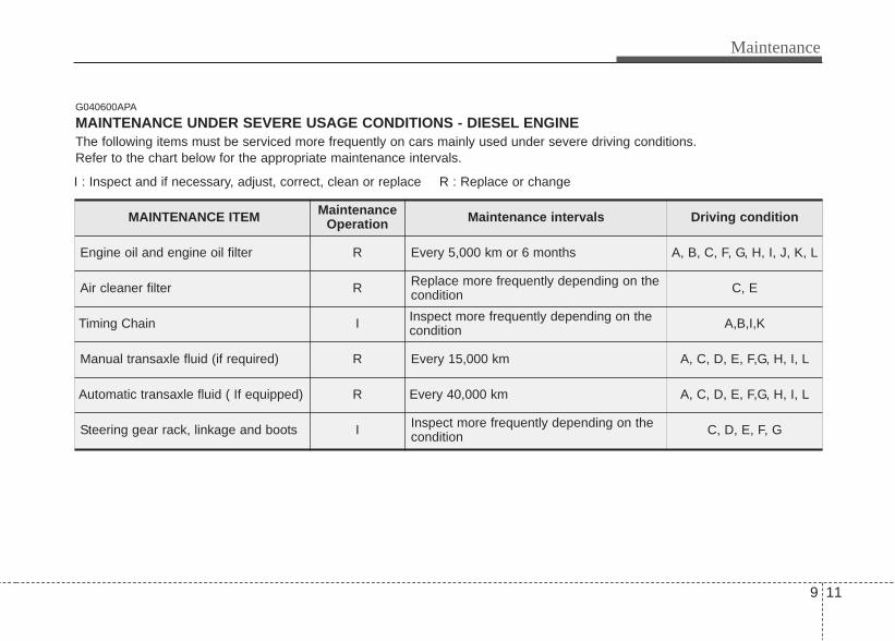
9 11
Maintenance
MAINTENANCE ITEM MaintenanceOperation Maintenance intervals Driving condition
Engine oil and engine oil filter R Every 5,000 km or 6 months A, B, C, F, G, H, I, J, K, L
Air cleaner filter R Replace more frequently depending on thecondition C, E
Timing Chain I Inspect more frequently depending on thecondition A,B,I,K
Manual transaxle fluid (if required) R Every 15,000 km A, C, D, E, F,G, H, I, L
Automatic transaxle fluid ( If equipped) R Every 40,000 km A, C, D, E, F,G, H, I, L
Steering gear rack, linkage and boots I Inspect more frequently depending on thecondition C, D, E, F, G
G040600APA
MAINTENANCE UNDER SEVERE USAGE CONDITIONS - DIESEL ENGINEThe following items must be serviced more frequently on cars mainly used under severe driving conditions.Refer to the chart below for the appropriate maintenance intervals.
I : Inspect and if necessary, adjust, correct, clean or replace R : Replace or change
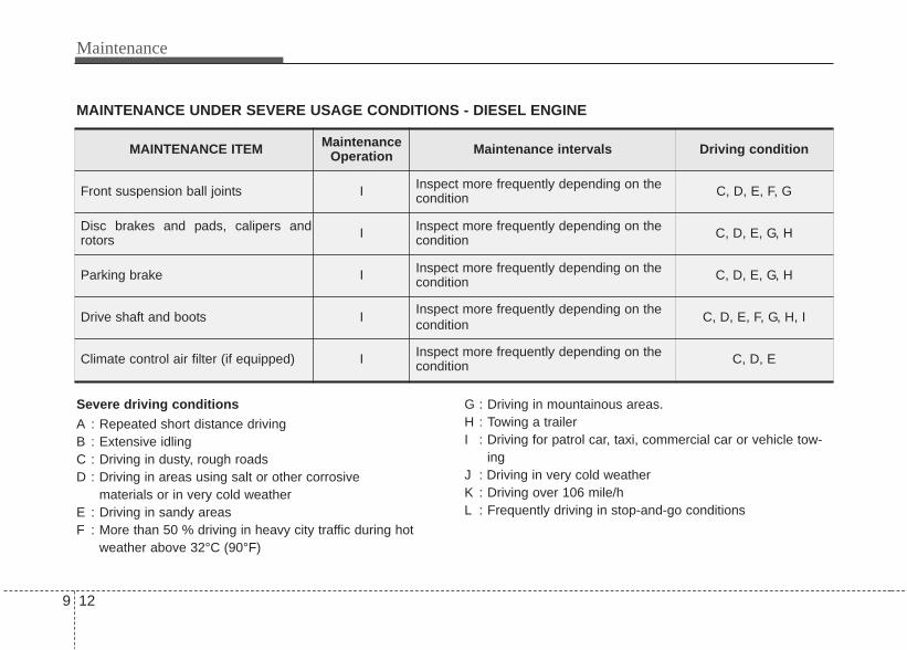
Maintenance
129
Severe driving conditionsA : Repeated short distance drivingB : Extensive idlingC : Driving in dusty, rough roadsD : Driving in areas using salt or other corrosive
materials or in very cold weatherE : Driving in sandy areasF : More than 50 % driving in heavy city traffic during hot
weather above 32°C (90°F)
G : Driving in mountainous areas.H : Towing a trailerI : Driving for patrol car, taxi, commercial car or vehicle tow-
ingJ : Driving in very cold weatherK : Driving over 106 mile/hL : Frequently driving in stop-and-go conditions
MAINTENANCE UNDER SEVERE USAGE CONDITIONS - DIESEL ENGINE
MAINTENANCE ITEM MaintenanceOperation Maintenance intervals Driving condition
Front suspension ball joints I Inspect more frequently depending on thecondition C, D, E, F, G
Disc brakes and pads, calipers androtors I Inspect more frequently depending on the
condition C, D, E, G, H
Parking brake I Inspect more frequently depending on thecondition C, D, E, G, H
Drive shaft and boots I Inspect more frequently depending on thecondition C, D, E, F, G, H, I
Climate control air filter (if equipped) I Inspect more frequently depending on thecondition C, D, E

9 13
Maintenance
G040500APB
NORMAL MAINTENANCE SCHEDULE - PETROL ENGINEMAINTENANCE
INTERVAL
MAINTENANCE ITEM
Number of months or driving distances, whichever comes firstKm x 1,000 1.5 10 20 30 40 50 60 70 80Months 2 12 24 36 48 60 72 84 96Years - 1 2 3 4 5 6 7 8
ENGINE COMPARTMENTEngine oil & filter *1 I R R R R R R R REngine Timing Chain - - - - I - - - IAir cleaner - C R C R C R C RBattery condition I I I I I I I I IUnder bonnet fluid level I I I I I I I I ISpark Plug - C C R C C R C CVacuum hose - I I I I I I I ICranckcase ventilation hose - I I I I I I I IBrake fluid - I I R I I R I IBolt and nuts on chasis and body I I I I I I I I IDrive belts alternator *2 - I I I I I I I ITensioner/idler/damper pulley Inspect when replacing the drive belt or timing chainEngine coolant *3 - I I R I I R I IManual transaxle fluid (if required) - I I R I I R I IAutomatic transaxle oil - I I I I I I I R
I : Inspect, R : Replace (After Inspection, Adjust,Repair,Clean or replace (if necessary) *1 : Check the engine oil and leak every 500 km or before starting a long trip.*2 : Adjust alternator and power steering and air conditioner drive belt(if equipped). Adjust & if necessary correct or repalace.*3 : When adding coolent,use only a qualified coolant additive for your vehicle and never mix hard water in the coolant filled at
the factory.An improper coolant mixture can result in serious malfunction or engine damage.

Maintenance
149
NORMAL MAINTENANCE SCHEDULE - PETROL ENGINE
MAINTENANCE INTERVAL
MAINTENANCE ITEM
Number of months or driving distances, whichever comes firstKm x 1,000 1.5 10 20 30 40 50 60 70 80Months 2 12 24 36 48 60 72 84 96Years - 1 2 3 4 5 6 7 8
VEHICLE ON FLOORENGINE BAYLubricate locks & hinges - - - - - - - - -Climate filter I I I I I I I I IBrake pedal / clutch pedal - I I I I I I I ICheck AC system for leaks and cooling I I I I I I I I ICooling system I I I I I I I I IVEHICLE ON LIFTManual gearbox I I I I I I I I IBrake pipes, hoses & connections - I I I I I I I IFuel filter - I I R I I R I ISuspension & steering system I I I I I I I I IFront suspension ball joints - I I I I I I I IFuel system, tank & lines I I I I I I I I IDriveshafts & boots - I I I I I I I IExhaust pipe & muffler - I I I I I I I I
L : Lubricate I : Inspect R : Replace (After Inspection, Adjust,Repair,Clean or replace (if necessary) *4 : The fuel filter is considered to be maintene free buy periodic inspection is recommended for this maintenance shedule
depends on fuel quality.if there are some important safety matters like fuel restriction,surging,loss of power,hard startingproblem etc,replace the fuel filter immeditely regardless of maintenance schedule and we recommend to consult an author-ized HYUNDAI dealer for detail.

9 15
Maintenance
NORMAL MAINTENANCE SCHEDULE - PETROL ENGINEMAINTENANCE
INTERVAL
MAINTENANCE ITEM
Number of months or driving distances, whichever comes firstKm x 1,000 1.5 10 20 30 40 50 60 70 80Months 2 12 24 36 48 60 72 84 96Years - 1 2 3 4 5 6 7 8
VEHICLE ON LIFTWheel Alignment & Balancing (if required) onchargeable basis - I I I I I I I I
Tyre Rotation & Balancing - TR TR TR TR TR TR TR TRParking brake (disc+internal shoe only) - I I I I I I I IFront & rear brake pads I I I I I I I I IFINAL CHECKSCheck all electrical systems *5 - - I - - I - - ICheck operation of all lights I I I I I I I I ICheck warning lamps operation I I I I I I I I ICheck/adjust parking brake I I I I I I I I IRoad test vehicle C C C C C C C C C
I : Inspect TR : Tyre Rotation C : Carry out

Maintenance
169
MAINTENANCE ITEM MaintenanceOperation Maintenance intervals Driving condition
Engine oil and engine oil filter R Every 5,000 Km or 6 months A, B, C, D, E, F, G, H, I, J
Air cleaner filter R Replace more frequently depending on thecondition C, E
Spark Plug R Replace more frequently depending on thecondition B, H
Timing Chain I Inspect more frequently depending on thecondition A,B,I,K
Manual transaxle fluid (if required) R Every 15,000 Km C, D, E, G, H, I, J
Automatic transaxle fluid ( If equipped) R Every 40,000 km C, D, E, G, H, I, K
Steering gear rack, linkage and boots I Inspect more frequently depending on thecondition C, D, E, F, G
G040600APA
MAINTENANCE UNDER SEVERE USAGE CONDITIONS - PETROL ENGINEThe following items must be serviced more frequently on cars mainly used under severe driving conditions.Refer to the chart below for the appropriate maintenance intervals.
I : Inspect and if necessary, adjust, correct, clean or replace R : Replace or change
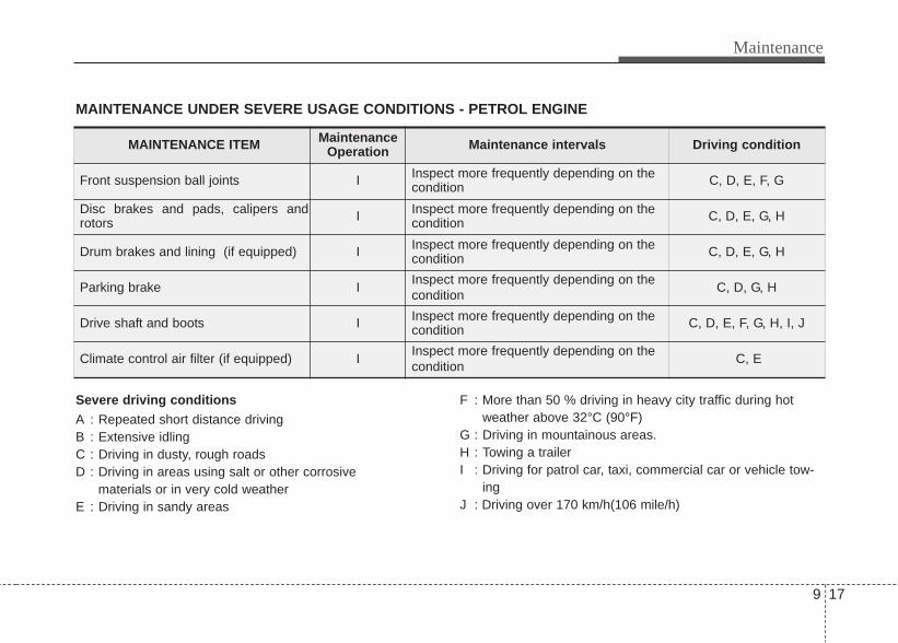
9 17
Maintenance
Severe driving conditionsA : Repeated short distance drivingB : Extensive idlingC : Driving in dusty, rough roadsD : Driving in areas using salt or other corrosive
materials or in very cold weatherE : Driving in sandy areas
F : More than 50 % driving in heavy city traffic during hotweather above 32°C (90°F)
G : Driving in mountainous areas.H : Towing a trailerI : Driving for patrol car, taxi, commercial car or vehicle tow-
ingJ : Driving over 170 km/h(106 mile/h)
MAINTENANCE UNDER SEVERE USAGE CONDITIONS - PETROL ENGINE
MAINTENANCE ITEM MaintenanceOperation Maintenance intervals Driving condition
Front suspension ball joints I Inspect more frequently depending on thecondition C, D, E, F, G
Disc brakes and pads, calipers androtors I Inspect more frequently depending on the
condition C, D, E, G, H
Drum brakes and lining (if equipped) I Inspect more frequently depending on thecondition C, D, E, G, H
Parking brake I Inspect more frequently depending on thecondition C, D, G, H
Drive shaft and boots I Inspect more frequently depending on thecondition C, D, E, F, G, H, I, J
Climate control air filter (if equipped) I Inspect more frequently depending on thecondition C, E

Maintenance
189
EXPLANATION OF SCHEDULED MAINTENANCE ITEMSEngine oil and filterThe engine oil and filter should bechanged at the intervals specified in themaintenance schedule. If the car is beingdriven in severe conditions, more fre-quent oil and filter changes are required.
Drive beltsInspect all drive belts for evidence ofcuts, cracks, excessive wear or oil satu-ration and replace if necessary. Drivebelts should be checked periodically forproper tension and adjusted as neces-sary.
Fuel filterA clogged filter can limit the speed atwhich the vehicle may be driven, dam-age the emission system and cause mul-tiple issues such as hard starting. If anexcessive amount of foreign matteraccumulates in the fuel tank, the filtermay require replacement more frequent-ly.After installing a new filter, run the enginefor several minutes, and check for leaksat the connections. We recommend thatthe Fuel filters should be installed by anauthorized HYUNDAI dealer.
Fuel lines, fuel hoses and con-nectionsCheck the fuel lines, fuel hoses and con-nections for leakage and damage. Haveany damaged or leaking parts replacedimmediately. We recommend to have itdone by an authorized HYUNDAI dealer.
WARNING - Diesel onlyNever work on injection systemwith engine running or within 30seconds after shutting off engine.High pressure pump, rail, injectorsand high pressure pipes are sub-ject to high pressure even after theengine stopped. The fuel jet pro-duced by fuel leaks may cause seri-ous injury, if it touch the body.People using pacemakers shouldnot move than 30cm closer to theECU or wiring harness within theengine room while engine is run-ning, since the high currents in theCommon Rail system produce con-siderable magnetic fields.

9 19
Maintenance
Vapor hose and fuel filler capThe vapor hose and fuel filler cap shouldbe inspected at those intervals specifiedin the maintenance schedule. Make surethat a new vapor hose or fuel filler cap iscorrectly replaced.
Vacuum crankcase ventilationhoses (if equipped)Inspect the surface of hoses for evidenceof heat and/or mechanical damage. Hardand brittle rubber, cracking, tears, cuts,abrasions, and excessive swelling indi-cate deterioration. Particular attentionshould be paid to examine those hosesurfaces nearest to high heat sources,such as the exhaust manifold.Inspect the hose routing to assure thatthe hoses do not come in contact withany heat source, sharp edges or movingcomponent which might cause heat dam-age or mechanical wear. Inspect all hoseconnections, such as clamps and cou-plings, to make sure they are secure, andthat no leaks are present. Hoses shouldbe replaced immediately if there is anyevidence of deterioration or damage.
Air cleaner filterA Genuine HYUNDAI air cleaner filter isrecommended when the filter isreplaced.
Spark plugs (for gasoline engine)Make sure to install new spark plugs ofthe correct heat range.
Valve clearance (for gasoline engine)Inspect excessive valve noise and/orengine vibration and adjust if necessary.We recommend that an authorizedHYUNDAI dealer should perform theoperation.
Cooling systemCheck cooling system components, suchas radiator, coolant reservoir, hoses andconnections for leakage and damage.Replace any damaged parts.
CoolantThe coolant should be changed at theintervals specified in the maintenanceschedule.
Manual transaxle fluid (if equipped)Inspect the manual transaxle fluidaccording to the maintenance schedule.
Automatic transaxle fluid (if equipped)The fluid level should be in the "HOT"range of the dipstick, after the engineand transaxle are at normal operatingtemperature. Check the automatictransaxle fluid level with the engine run-ning and the transaxle in neutral, with theparking brake properly applied.

Maintenance
209
Brake hoses and linesVisually check for proper installation,chafing, cracks, deterioration and anyleakage. Replace any deteriorated ordamaged parts immediately.
Brake fluidCheck brake fluid level in the brake fluidreservoir. The level should be between“MIN” and “MAX” marks on the side ofthe reservoir. Use only hydraulic brakefluid conforming to DOT 3 or DOT 4specification.
Parking brakeInspect the parking brake system includ-ing the parking brake lever and cables.
Brake discs, pads, calipers androtorsCheck the pads for excessive wear,discs for run out and wear, and calipersfor fluid leakage.
Suspension mounting boltsCheck the suspension connections forlooseness or damage. Retighten to thespecified torque.
Steering gear box, linkage &boots/lower arm ball jointWith the vehicle stopped and engine off,check for excessive free-play in thesteering wheel.Check the linkage for bends or damage.Check the dust boots and ball joints fordeterioration, cracks, or damage.Replace any damaged parts.
Drive shafts and bootsCheck the drive shafts, boots and clampsfor cracks, deterioration, or damage.Replace any damaged parts and, if nec-essary, repack the grease.
Air conditioning refrigerant (if equipped)Check the air conditioning lines and con-nections for leakage and damage.

9 21
Maintenance
ENGINE OIL
Checking the engine oil level 1. Be sure the vehicle is on level ground.2. Start the engine and allow it to reach
normal operating temperature.3. Turn the engine off and wait for a few
minutes (about 5 minutes) for the oil toreturn to the oil pan.
4. Pull the dipstick out, wipe it clean, andre-insert it fully.
5. Pull the dipstick out again and checkthe level. The level should be betweenF and L.
If it is near or at L, add enough oil to bringthe level to F. Do not overfill.
Use a funnel to help prevent oil frombeing spilled on engine components.
Use only the specified engine oil. (Referto “Recommended lubricants and capaci-ties” in section 8.)
WARNING - Radiatorhose
Be very careful not to touch theradiator hose when checking oradding the engine oil as it may behot enough to burn you.
ORBC070003
CAUTION• Do not overfill with engine oil.
Engine damage may result.• Do not spill engine oil, when
adding or changing engine oil. Ifyou drop the engine oil on theengine room, wipe it off immediate-ly.
ORB070004
CAUTION - Diesel engineOverfilling the engine oil may causesevere dieseling due to churningeffect. It may lead to engine damageaccompanied with abrupt enginespeed increment, combustion noiseand white smoke emission.

Maintenance
229
Changing the engine oil and filterHave engine oil and filter changedaccording to the Maintenance Scheduleat the beginning of this section. We rec-ommend to have it done by an author-ized HYUNDAI dealer.
WARNINGUsed engine oil may cause irrita-tion or cancer of the skin if left incontact with the skin for prolongedperiods of time. Used engine oilcontains chemicals that havecaused cancer in laboratory ani-mals. Always protect your skin bywashing your hands thoroughlywith soap and warm water as soonas possible after handling used oil.

9 23
Maintenance
ENGINE COOLANTThe high-pressure cooling system has areservoir filled with year-round antifreezecoolant. The reservoir is filled at the fac-tory.Check the antifreeze protection andcoolant level at least once a year, at thebeginning of the winter season, andbefore traveling to a colder climate.
Checking the coolant level
WARNINGRemoving radiatorcap
• Never attempt to remove the radi-ator cap while the engine is oper-ating or hot. Doing so might leadto cooling system and enginedamage and could result in seri-ous personal injury from escap-ing hot coolant or steam.
• Turn the engine off and wait untilit cools down. Use extreme carewhen removing the radiator cap.Wrap a thick towel around it, andturn it counterclockwise slowlyto the first stop. Step back whilethe pressure is released from thecooling system. When you aresure all the pressure has beenreleased, press down on the cap,using a thick towel, and continueturning counterclockwise toremove it.
(Continued)
(Continued)• Even if the engine is not operat-
ing, do not remove the radiatorcap or the drain plug while theengine and radiator are hot. Hotcoolant and steam may still blowout under pressure, causing seri-ous injury.
WARNING The electric motor (cool-ing fan) is controlled byengine coolant tempera-ture, refrigerant pres-sure and vehicle speed.
It may sometimes operate evenwhen the engine is not running.Use extreme caution when workingnear the blades of the cooling fanso that you are not injured by arotating fan blades. As the enginecoolant temperature decreases, theelectric motor will automaticallyshut off. This is a normal condition.

Maintenance
249
Check the condition and connections ofall cooling system hoses and heaterhoses. Replace any swollen or deterio-rated hoses.The coolant level should be filledbetween F and L marks on the side of thecoolant reservoir when the engine iscool.
If the coolant level is low, add enoughspecified coolant to provide protectionagainst freezing and corrosion. Bring thelevel to F, but do not overfill. If frequentadditions are required, have the coolingsystem inspected. We recommend tohave it done by an authorized HYUNDAIdealer.
To add coolant follow the below steps:(Gasoline Engine only)1. Open the cap.2. Pull the sliding neck up and turn it in
the direction of the arrow to fix it inplace.
3. Add coolant.
ORB070067
■ Gasoline Engine
ORB070005
ORB070066
■ Gasoline Engine
■ Diesel Engine

9 25
Maintenance
Recommended engine coolant• When adding coolant, use only deion-
ized water or soft water for your vehi-cle and never mix hard water in thecoolant filled at the factory. An improp-er coolant mixture can result in seriousmalfunction or engine damage.
• The engine in your vehicle has alu-minum engine parts and must be pro-tected by an ethylene-glycol-basedcoolant to prevent corrosion and freez-ing.
• DO NOT USE alcohol or methanolcoolant or mix them with the specifiedcoolant.
• Do not use a solution that containsmore than 60% antifreeze or less than35% antifreeze, which would reducethe effectiveness of the solution.
For mixture percentage, refer to the fol-lowing table.
Changing the coolantHave coolant changed according to theMaintenance Schedule at the beginningof this section. We recommend to have itdone by an authorized HYUNDAI dealer.
CAUTIONPut a thick cloth around the radiatorcap before refilling the coolant inorder to prevent the coolant fromoverflowing into engine parts suchas the generator.
WARNING - Coolant• Do not use radiator coolant or
antifreeze in the washer fluidreservoir.
• Radiator coolant can severelyobscure visibility when sprayedon the windshield and may causeloss of vehicle control or damageto paint and body trim.
ORBC070006
AmbientTemperature
Mixture Percentage (volume)
Antifreeze Water-15°C (5°F) 30 70
-25°C (-13°F) 40 60
-35°C (-31°F) 50 50
-45°C (-49°F) 60 40
WARNINGRadiator cap
Do not remove the radiator capwhen the engine and radiator arehot. Scalding hot coolant andsteam may blow out under pres-sure causing serious injury.

Maintenance
269
BRAKE/CLUTCH FLUID
Checking the brake/clutch fluidlevel Check the fluid level in the reservoir peri-odically. The fluid level should bebetween MAX and MIN marks on theside of the reservoir.Before removing the reservoir cap andadding brake fluid, clean the area aroundthe reservoir cap thoroughly to preventbrake fluid contamination.If the level is low, add fluid to the MAXlevel. The level will fall with accumulatedmileage. This is a normal condition asso-ciated with the wear of the brake linings.If the fluid level is excessively low, havethe brake or clutch system checked. Werecommend to have it done by an author-ized HYUNDAI dealer.
Use only the specified brake fluid. (Referto “Recommended lubricants or capaci-ties” in section 8.)
Never mix different types of fluid.
WARNING - Brake fluidWhen changing and adding brakefluid, handle it carefully. Do not letit come in contact with your eyes. Ifbrake fluid should come in contactwith your eyes, immediately flushthem with a large quantity of freshtap water. Have your eyes exam-ined by a doctor as soon as possi-ble.
WARNING - Loss of brakefluid
In the event the brake systemrequires frequent additions of fluid,Have the vehicle inspected. We rec-ommend to have it done by anauthorized HYUNDAI dealer. CAUTION
Do not allow brake fluid to contactthe vehicle's body paint, as paintdamage will result. Brake fluid,which has been exposed to open airfor an extended time should neverbe used as its quality cannot beguaranteed. It should be disposedof properly. Don't put in the wrongkind of fluid. A few drops of miner-al-based oil, such as engine oil, inyour brake system can damagebrake system parts.
ORBI071007

9 27
Maintenance
AUTOMATIC TRANSAXLE FLUID (IF EQUIPPED)
Checking the automatic transaxlefluid level The automatic transaxle fluid levelshould be checked regularly.Keep the vehicle on the level ground withthe parking brake applied and check thefluid level according to the following pro-cedure.1. Place the selector lever in N (Neutral)
position and confirm the engine is run-ning at normal idle speed.
2. After the transaxle is warmed up suffi-ciently (fluid temperature 70~80°C(158~176°F), for example by 10 min-utes usual driving, move the shift leverthrough all positions then place theselector lever in “N (Neutral) or P(Park)” position.
3. Confirm that the fluid level is in “HOT”range on the level gauge. If the fluidlevel is lower, add the specified fluidfrom the fill hole. If the fluid level ishigher, drain the fluid from the drainhole.
4. If the fluid level is checked in cold con-dition (fluid temperature 20~30°C(68~86°F) add the fluid to “C” (COLD)line and then recheck the fluid levelaccording to the above step 2.
ORBC070008 OHD076045N
Maintenance
289
✽ NOTICE“C” (COLD) range is for reference onlyand should NOT be used to determinetransaxle fluid level.
✽ NOTICENew automatic transaxle fluid should bered. The red dye is added so the assem-bly plant can identify it as automatictransaxle fluid and distinguish it fromengine oil or antifreeze. The red dye,which is not an indicator of fluid quali-ty, is not permanent. As the vehicle isdriven, the automatic transaxle fluidwill begin to look darker. The color mayeventually appear light brown.Therefore, have the automatic transaxlefluid changed according to theMaintenance Schedule at the beginningof this section. We recommend to have itdone by an authorized HYUNDAI deal-er.
Use only the specified automatictransaxle fluid. (Refer to “Recommendedlubricants and capacities” in section 8.)
Changing the automatic transaxlefluidHave the automatic transaxle fluidchanged according to the MaintenanceSchedule at the beginning of this section.We recommend to have it done by anauthorized HYUNDAI dealer.
WARNING - Transaxlefluid
The transaxle fluid level should bechecked when the engine is at nor-mal operating temperature. Thismeans that the engine, radiator,radiator hose and exhaust systemetc., are very hot. Exercise greatcare not to burn yourself during
WARNING - Parking brakeTo avoid sudden movement of thevehicle, apply parking brake anddepress the brake pedal beforemoving the shift lever.
CAUTION• Low fluid level causes transaxle
slippage. Overfilling can causefoaming, loss of fluid and transaxlemalfunction.
• The use of a non-specified fluidcould result in transaxle malfunc-tion and failure.
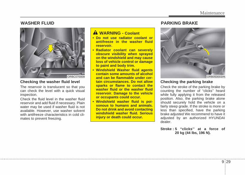
9 29
Maintenance
WASHER FLUID
Checking the washer fluid level The reservoir is translucent so that youcan check the level with a quick visualinspection.Check the fluid level in the washer fluidreservoir and add fluid if necessary. Plainwater may be used if washer fluid is notavailable. However, use washer solventwith antifreeze characteristics in cold cli-mates to prevent freezing.
Checking the parking brakeCheck the stroke of the parking brake bycounting the number of “clicks’’ heardwhile fully applying it from the releasedposition. Also, the parking brake aloneshould securely hold the vehicle on afairly steep grade. If the stroke is more orless than specified, have the parkingbrake adjusted We recommend to have itadjusted by an authorized HYUNDAIdealer.
Stroke : 5 “clicks’’ at a force of 20 kg (44 lbs, 196 N).
WARNING - Coolant• Do not use radiator coolant or
antifreeze in the washer fluidreservoir.
• Radiator coolant can severelyobscure visibility when sprayedon the windshield and may causeloss of vehicle control or damageto paint and body trim.
• Windshield Washer fluid agentscontain some amounts of alcoholand can be flammable under cer-tain circumstances. Do not allowsparks or flame to contact thewasher fluid or the washer fluidreservoir. Damage to the vehicleor occupants could occur.
• Windshield washer fluid is poi-sonous to humans and animals.Do not drink and avoid contactingwindshield washer fluid. Seriousinjury or death could occur.
ORBC070009 ORB050003/H
PARKING BRAKE

Maintenance
309
FUEL FILTER (FOR DIESEL)Draining water from the fuel filterThe fuel filter for diesel engine plays animportant role of separating water fromfuel and accumulating the water in itsbottom.If water accumulates in the fuel filter, thewarning light comes on when the ignitionswitch is in the ON position.
If this warning light illuminates,have the water drained andthe system checked. We rec-ommend to have it done by anauthorized HYUNDAI dealer.
Extracting air from the fuel filterIf you drive until you have no fuel left or ifyou replace the fuel filter, be sure toextract air from the fuel system as itmakes it difficult to start the engine.1. Pump up and down(1) approximately
50 times until the pump is hard.2. Extract air from the fuel filter by
removing the bolt(2) with a cross-tipscrew driver and reinstall the bolt(2).
3. Pump up and down(1) approximately15 times.
4. Extract air from the fuel filter byremoving the bolt(2) with a cross-tipscrew driver and reinstall the bolt(2).
5. Pump up and down(1) approximately5 times.
✽ NOTICE• Use cloths when you extract air so that
the fuel is not sprayed around.• Clean the fuel around the fuel filter or
the injection pump before starting theengine to prevent fire.
• Finally, check each part if the fuel isleaking.
Fuel filter cartridge replacement
✽ NOTICEWhen replacing the fuel filter cartridge,we recommend to use parts availablefrom an authorized HYUNDAI dealer.CAUTION
If the water accumulated in the fuelfilter is not drained at proper times,damages to the major parts such asthe fuel system can be caused bywater permeation in the fuel filter.
ORB070063

9 31
Maintenance
AIR CLEANER
Filter replacement It must be replaced when necessary, andshould not be washed.You can clean the filter when inspectingthe air cleaner element.Clean the filter by using compressed air.
1. Loosen the air cleaner cover attachingclips and open the cover.
2. Wipe the inside of the air cleaner.3. Replace the air cleaner filter. 4. Lock the cover with the cover attach-
ing clips.Replace the filter according to theMaintenance Schedule.If the vehicle is operated in extremelydusty or sandy areas, replace the element more often than the usual recommended intervals. (Refer to“Maintenance under severe usage condi-tions” in this section.)
ORB070010 ORB070011 ORB070012

Maintenance
329
CAUTION• Do not drive with the air cleaner
removed; this will result in exces-sive engine wear.
• When removing the air cleaner fil-ter, be careful that dust or dirtdoes not enter the air intake, ordamage may result.
• We recommend to use partsavailable at an authorizedHYUNDAI dealer. Use of non-gen-uine parts could damage the airflow sensor or turbochager.

9 33
Maintenance
CLIMATE CONTROL AIR FILTER (IF EQUIPPED)Filter inspectionIf the vehicle is operated in the severelyair-polluted cities or on dusty roughroads for a long period, it should beinspected more frequently and cleanedearlier. When you, the owner, clean theclimate control air filter, clean it perform-ing the following procedure, and be care-ful to avoid damaging other components. Clean the filter according to the mainte-nance Schedule.
Filter replacement1. With the glove box open, remove the
stoppers by turning them counter-clockwise on both sides.
2. Remove the climate control air filtercover while pressing the lock of thecover.
ORBI071013 ORB070014/H

Maintenance
349
3. Clean the climate control air filter byone of the method below.- Dust the dirt off- Use a vacuum clean- Wash with a soft brush, and then dry
the filter thoroughly4. Reassemble in the reverse order of
disassembly.
✽ NOTICEWhen replacing the climate control airfilter install it properly. Otherwise, thesystem may produce noise and the effec-tiveness of the filter may be reduced.
ORBI071015

9 35
Maintenance
WIPER BLADES
Blade inspection✽ NOTICECommercial hot waxes applied by auto-matic car washes have been known tomake the windshield difficult to clean.
Contamination of either the windshield orthe wiper blades with foreign matter canreduce the effectiveness of the wind-shield wipers. Common sources of con-tamination are insects, tree sap, and hotwax treatments used by some commer-cial car washes. If the blades are not wip-ing properly, clean both the window andthe blades with a good cleaner or milddetergent, and rinse thoroughly withclean water.
Blade replacement When the wipers no longer clean ade-quately, the blades may be worn orcracked, and require replacement.
1JBA5122/H CAUTIONTo prevent damage to the wiperblades, do not use gasoline,kerosene, paint thinner, or othersolvents on or near them.
CAUTIONTo prevent damage to the wiperarms or other components, do notattempt to move the wipers manual-ly.
CAUTIONThe use of a non-specified wiperblade could result in wiper malfunc-tion and failure.

Maintenance
369
Front windshield wiper blade 1. Raise the wiper arm and turn the
wiper blade assembly to expose theplastic locking clip.
2. Compress the clip and slide the bladeassembly downward.
3. Lift it off the arm.4. Install the blade assembly in the
reverse order of removal.
OLM079200/H OLM079201R OLM079202/H
CAUTIONDo not allow the wiper arm to fallagainst the windshield, since it maychip or crack the windshield.

9 37
Maintenance
BATTERY
For best battery service• Keep the battery securely mounted.• Keep the battery top clean and dry.• Keep the terminals and connections
clean, tight, and coated with petroleumjelly or terminal grease.
• Rinse any spilled electrolyte from thebattery immediately with a solution ofwater and baking soda.
• If the vehicle is not going to be used foran extended time, disconnect the bat-tery cables.
WARNING - Battery dangers
Always read the followinginstructions carefully whenhandling a battery.
Keep lighted cigarettes andall other flames or sparksaway from the battery.
Hydrogen, a highly com-bustible gas, is alwayspresent in battery cells andmay explode if ignited.
Keep batteries out of thereach of children becausebatteries contain highlycorrosive SULFURIC ACID.Do not allow battery acid tocontact your skin, eyes,clothing or paint finish.
(Continued)
(Continued)
If any electrolyte gets intoyour eyes, flush your eyeswith clean water for at least15 minutes and get immedi-ate medical attention. If electrolyte gets on yourskin, thoroughly wash thecontacted area. If you feel apain or a burning sensa-tion, get medical attentionimmediately.
Wear eye protection whencharging or working near abattery. Always provideventilation when working inan enclosed space.
An inappropriately disposedbattery can be harmful tothe environment and humanhealth. Dispose the batteryaccording to your locallaw(s) or regulation.
(Continued)
Pb
ORBI071016

Maintenance
389
Battery recharging Your vehicle has a maintenance-free,calcium-based battery.• If the battery becomes discharged in a
short time (because, for example, theheadlights or interior lights were left onwhile the vehicle was not in use),recharge it by slow charging (trickle)for 10 hours.
• If the battery gradually dischargesbecause of high electric load while thevehicle is being used, recharge it at 20-30A for two hours.
(Continued)• When lifting a plastic-cased bat-
tery, excessive pressure on thecase may cause battery acid toleak, resulting in personal injury.Lift with a battery carrier or withyour hands on opposite corners.
• Never attempt to recharge thebattery when the battery cablesare connected.
• The electrical ignition systemworks with high voltage. Nevertouch these components with theengine running or the ignitionswitched on.
Failure to follow the above warn-ings can result in serious bodilyinjury or death.
CAUTION• When you don’t use the vehicle
for a long time in the low temper-ature area, separate the batteryand keep it indoors.
• Always charge the battery fully toprevent the battery case dam-aged in low temperature area.
• If you use unauthorized electricdevices, the battery may be dis-charged. Never use unauthorizeddevices.
WARNINGWe recommend that separating thebattery from the vehicle should bedone in an authorized HYUNDAIdealer.

9 39
Maintenance
Reset itemsItems should be reset after the batteryhas been discharged or the battery hasbeen disconnected.• Auto up/down window (See section 6)• Sunroof (See section 6)• Trip computer (See section 6)• Climate control system
(See section 6)• Clock (See section 6)• Audio (See section 6)
WARNING• Before performing maintenance
or recharging the battery, turn offall accessories and stop theengine.
• The negative battery cable mustbe removed first and installedlast when the battery is discon-nected.
• We recommend that operationrelated to the battery should bedone in an authorized HYUNDAIdealer.
CAUTION• Keep the battery away from water
or any liquid.• For your safety, we recommend
to use the authenticity byapproved authorized HYUNDAIdealer, when you replace the bat-tery.
WARNING - Rechargingbattery
When recharging the battery,observe the following precautions:• The battery must be removed
from the vehicle and placed in anarea with good ventilation.
• Do not allow cigarettes, sparks,or flame near the battery.
• Watch the battery during charg-ing, and stop or reduce thecharging rate if the battery cellsbegin gassing (boiling) violentlyor if the temperature of the elec-trolyte of any cell exceeds 49°C(120°F).
• Wear eye protection when check-ing the battery during charging.
• Disconnect the battery charger inthe following order.
1. Turn off the battery charger mainswitch.
2. Unhook the negative clamp fromthe negative battery terminal.
3. Unhook the positive clamp fromthe positive battery terminal.

Maintenance
409
TIRES AND WHEELS Tire care For proper maintenance, safety, andmaximum fuel economy, you mustalways maintain recommended tireinflation pressures and stay withinthe load limits and weight distributionrecommended for your vehicle.
Recommended cold tire inflationpressures All tire pressures (including thespare) should be checked when thetires are cold. “Cold Tires” means thevehicle has not been driven for atleast three hours or driven less than1.6 km (one mile).Recommended pressures must bemaintained for the best ride, topvehicle handling, and minimum tirewear.For recommended inflation pressure,refer to “Tire and wheels” in section10.
All specifications (sizes and pres-sures) can be found on a labelattached to the vehicle.
WARNING - Tire underin-flation
Severe underinflation can leadto severe heat build-up, causingblowouts, tread separation andother tire failures that can resultin the loss of vehicle controlleading to severe injury ordeath. This risk is much higheron hot days and when drivingfor long periods at high speeds.
ORBI071017
CAUTION• Underinflation also results in
excessive wear, poor handlingand reduced fuel economy.Wheel deformation also ispossible. Keep your tire pres-sures at the proper levels. If atire frequently needs refilling,have it checked. We recom-mend to have it done by anauthorized HYUNDAI dealer.
• Overinflation produces aharsh ride, excessive wear atthe center of the tire tread,and a greater possibility ofdamage from road hazards.

9 41
Maintenance
Checking tire inflation pressureCheck your tires once a month ormore.Also, check the tire pressure of thespare tire.
How to checkUse a good quality gage to check tirepressure. You can not tell if your tiresare properly inflated simply by look-ing at them. Radial tires may lookproperly inflated even when they'reunderinflated.Check the tire's inflation pressurewhen the tires are cold. - "Cold"means your vehicle has been sittingfor at least three hours or driven nomore than 1.6 km (1 mile).WARNING - Tire Inflation
Overinflation or underinflationcan reduce tire life, adverselyaffect vehicle handling, andlead to sudden tire failure. Thiscould result in loss of vehiclecontrol and potential injury.
CAUTION - Tire pressureAlways observe the following:• Check tire pressure when the
tires are cold. (After vehiclehas been parked for at leastthree hours or hasn't beendriven more than 1.6 km (onemile) since startup.)
• Check the pressure of yourspare tire each time you checkthe pressure of other tires.
• Never overload your vehicle.Be careful not to overload avehicle luggage rack if yourvehicle is equipped with one.
• Worn, old tires can causeaccidents. If your tread isbadly worn, or if your tireshave been damaged, replacethem.
CAUTION• Warm tires normally exceed
recommended cold tire pres-sures by 28 to 41 kPa (4 to 6psi). Do not release air fromwarm tires to adjust the pres-sure or the tires will be under-inflated.
• Be sure to reinstall the tireinflation valve caps. Withoutthe valve cap, dirt or moisturecould get into the valve coreand cause air leakage. If avalve cap is missing, install anew one as soon as possible.

Maintenance
429
Remove the valve cap from the tirevalve stem. Press the tire gage firm-ly onto the valve to get a pressuremeasurement. If the cold tire inflationpressure matches the recommendedpressure on the tire and loadinginformation label, no further adjust-ment is necessary. If the pressure islow, add air until you reach the rec-ommended amount.If you overfill the tire, release air bypushing on the metal stem in thecenter of the tire valve. Recheck thetire pressure with the tire gage. Besure to put the valve caps back onthe valve stems. They help preventleaks by keeping out dirt and mois-ture.
Tire rotation To equalize tread wear, it is recom-mended that the tires be rotatedevery 10,000 km or sooner if irregu-lar wear develops.During rotation, check the tires forcorrect balance.When rotating tires, check foruneven wear and damage. Abnormalwear is usually caused by incorrecttire pressure, improper wheel align-ment, out-of-balance wheels, severebraking or severe cornering. Look forbumps or bulges in the tread or sideof tire. Replace the tire if you findeither of these conditions. Replacethe tire if fabric or cord is visible.After rotation, be sure to bring thefront and rear tire pressures to spec-ification and check lug nut tightness.
WARNING• Inspect your tires frequently
for proper inflation as well aswear and damage. Always usea tire pressure gauge.
• Tires with too much or too lit-tle pressure wear unevenlycausing poor handling, loss ofvehicle control, and suddentire failure leading to acci-dents, injuries, and evendeath. The recommended coldtire pressure for your vehiclecan be found in this manualand on the tire label located onthe driver's side center pillar.
• Worn tires can cause acci-dents. Replace tires that areworn, show uneven wear, orare damaged.
• Remember to check the pres-sure of your spare tire.HYUNDAI recommends thatyou check the spare everytime you check the pressureof the other tires on your vehi-cle.

9 43
Maintenance
Disc brake pads should be inspectedfor wear whenever tires are rotated.
✽ NOTICERotate radial tires that have anasymmetric tread pattern only fromfront to rear and not from right toleft.
Wheel alignment and tire balance The wheels on your vehicle werealigned and balanced carefully at thefactory to give you the longest tire lifeand best overall performance.In most cases, you will not need tohave your wheels aligned again.However, if you notice unusual tirewear or your vehicle pulling one wayor the other, the alignment may needto be reset. If you notice your vehicle vibratingwhen driving on a smooth road, yourwheels may need to be rebalanced.
S2BLA790
S2BLA790A
Without a spare tire
With a full-size spare tire (if equipped)
WARNING• Do not use the compact spare
tire for tire rotation.• Do not mix bias ply and radial
ply tires under any circum-stances. This may causeunusual handling characteris-tics that could result in death,severe injury, or propertydamage.
CAUTIONImproper wheel weights candamage your vehicle's alu-minum wheels. Use onlyapproved wheel weights.

Maintenance
449
Tire replacementIf the tire is worn evenly, a treadwear indicator will appear as a solidband across the tread. This showsthere is less than 1.6 mm (1/16 inch)of tread left on the tire. Replace thetire when this happens.Do not wait for the band to appearacross the entire tread before replac-ing the tire.
OEN076053
Tread wear indicator (Continued)• The use of any other tire size
or type may seriously affectride, handling, ground clear-ance, stopping distance, bodyto tire clearance, snow tireclearance, and speedometerreliability.
• It is best to replace all fourtires at the same time. If thatis not possible, or necessary,then replace the two front ortwo rear tires as a pair.Replacing just one tire canseriously affect your vehicle’shandling.
• The ABS works by comparingthe speed of the wheels. Tiresize can affect wheel speed.When replacing tires, all 4tires must use the same sizeoriginally supplied with thevehicle. Using tires of a differ-ent size can cause the ABS(Anti-lock Brake System) andESP (Electronic StabilityProgram) (if equipped) towork irregularly.
WARNING - Replacingtires
• Driving on worn-out tires isvery hazardous and willreduce braking effectiveness,steering accuracy, and trac-tion.
• Your vehicle is equipped withtires designed to provide forsafe ride and handling capa-bility. Do not use a size andtype of tire and wheel that isdifferent from the one that isoriginally installed on yourvehicle. It can affect the safe-ty and performance of yourvehicle, which could lead tohandling failure or rolloverand serious injury. Whenreplacing the tires, be sure toequip all four tires with thetire and wheel of the samesize, type, tread, brand andload-carrying capacity.
(Continued)

9 45
Maintenance
Wheel replacement When replacing the metal wheels forany reason, make sure the newwheels are equivalent to the originalfactory units in diameter, rim widthand offset.
Tire tractionTire traction can be reduced if youdrive on worn tires, tires that areimproperly inflated or on slipperyroad surfaces. Tires should bereplaced when tread wear indicatorsappear. To reduce the possibility oflosing control, slow down wheneverthere is rain, snow or ice on the road.
Tire maintenance In addition to proper inflation, correctwheel alignment helps to decreasetire wear. If you find a tire is wornunevenly, have your dealer checkthe wheel alignment.When you have new tires installed,make sure they are balanced. Thiswill increase vehicle ride comfort andtire life. Additionally, a tire shouldalways be rebalanced if it is removedfrom the wheel.
Tire sidewall labelingThis information identifies anddescribes the fundamental charac-teristics of the tire and also providesthe tire identification number (TIN)for safety standard certification. TheTIN can be used to identify the tire incase of a recall.
1. Manufacturer or brand nameManufacturer or Brand name isshown.
WARNINGA wheel that is not the correctsize may adversely affect wheeland bearing life, braking andstopping abilities, handlingcharacteristics, ground clear-ance, body-to-tire clearance,snow chain clearance,speedometer and odometer cal-ibration, headlight aim andbumper height.
I030B04JM
1
1
23
4
5,6
7

Maintenance
469
2. Tire size designation A tire’s sidewall is marked with a tiresize designation. You will need thisinformation when selecting replace-ment tires for your car. The followingexplains what the letters and num-bers in the tire size designationmean.Example tire size designation:(These numbers are provided as anexample only; your tire size designa-tor could vary depending on yourvehicle.)195/55R16 84H
195 - Tire width in millimeters.55 - Aspect ratio. The tire’s section
height as a percentage of itswidth.
R - Tire construction code (Radial).16 - Rim diameter in inches.84 - Load Index, a numerical code
associated with the maximumload the tire can carry.
H - Speed Rating Symbol. See thespeed rating chart in this sectionfor additional information.
Wheel size designation Wheels are also marked with impor-tant information that you need if youever have to replace one. The fol-lowing explains what the letters andnumbers in the wheel size designa-tion mean.
Example wheel size designation:6.0JX16
6.0 - Rim width in inches.J - Rim contour designation.16 - Rim diameter in inches.
Tire speed ratings The chart below lists many of the dif-ferent speed ratings currently beingused for passenger car tires. Thespeed rating is part of the tire sizedesignation on the sidewall of thetire. This symbol corresponds to thattire's designed maximum safe oper-ating speed.
S 180 km/h (112 mph)T 190 km/h (118 mph)H 210 km/h (130 mph)V 240 km/h (149 mph)Z Above 240 km/h (149 mph)
Maximum SpeedSpeedRatingSymbol

9 47
Maintenance
3. Checking tire life (TIN : TireIdentification Number)
Any tires that are over 6 years old,based on the manufacturing date,(including the spare tire) should bereplaced by new ones. You can findthe manufacturing date on the tiresidewall (possibly on the inside ofthe wheel), displaying the DOTCode. The DOT Code is a series ofnumbers on a tire consisting of num-bers and English letters. The manu-facturing date is designated by thelast four digits (characters) of theDOT code.
DOT : XXXX XXXX OOOOThe front part of the DOT means aplant code number, tire size andtread pattern and the last four num-bers indicate week and year manu-factured.For example: DOT XXXX XXXX 1611 representsthat the tire was produced in the 16thweek of 2011.
4. Tire ply composition and materialThe number of layers or plies of rub-ber-coated fabric in the tire. Tiremanufacturers also must indicate thematerials in the tire, which includesteel, nylon, polyester, and others.The letter "R" means radial ply con-struction; the letter "D" means diago-nal or bias ply construction; and theletter "B" means belted-bias ply con-struction.
5. Maximum permissible inflationpressure
This number is the greatest amountof air pressure that should be put inthe tire. Do not exceed the maximumpermissible inflation pressure. Referto the Tire and Loading Informationlabel for recommended inflationpressure.
WARNING - Tire ageTires degrade over time, evenwhen they are not being used.Regardless of the remainingtread, it is recommended thattires generally be replaced aftersix (6) years of normal service.Heat caused by hot climates orfrequent high loading condi-tions can accelerate the agingprocess. Failure to follow thiswarning can result in suddentire failure, which could lead toa loss of control and an acci-dent involving serious injury ordeath.

Maintenance
489
6. Maximum load ratingThis number indicates the maximumload in kilograms and pounds thatcan be carried by the tire. Whenreplacing the tires on the vehicle,always use a tire that has the sameload rating as the factory installedtire.
7. Uniform tire quality grading Quality grades can be found whereapplicable on the tire sidewallbetween tread shoulder and maxi-mum section width. For example: TREADWEAR 200 TRACTION AA TEMPERATURE A
Tread wearThe tread wear grade is a compara-tive rating based on the wear rate ofthe tire when tested under controlledconditions on a specified govern-ment test course. For example, a tiregraded 150 would wear one-and-a-half times (1½) as well on the gov-ernment course as a tire graded 100.The relative performance of tiresdepends upon the actual conditionsof their use, however, and maydepart significantly from the normdue to variations in driving habits,service practices and differences inroad characteristics and climate.
These grades are molded on theside-walls of passenger vehicle tires.The tires available as standard oroptional equipment on your vehiclemay vary with respect to grade.
Traction - AA, A, B & C The traction grades, from highest tolowest, are AA, A, B and C. Thosegrades represent the tire’s ability tostop on wet pavement as measuredunder controlled conditions on spec-ified government test surfaces ofasphalt and concrete. A tire markedC may have poor traction perform-ance.
WARNING The traction grade assigned tothis tire is based on straight-ahead braking traction tests,and does not include accelera-tion, cornering, hydroplaning,or peak traction characteristics.

9 49
Maintenance
Temperature -A, B & C The temperature grades are A (thehighest), B, and C, representing thetire’s resistance to the generation ofheat and its ability to dissipate heatwhen tested under controlled condi-tions on a specified indoor laboratorytest wheel. Sustained high temperature cancause the material of the tire todegenerate and reduce tire life, andexcessive temperature can lead tosudden tire failure. Grades B and Arepresent higher levels of perform-ance on the laboratory test wheelthan the minimum required by law.
WARNING - Tire temperature
The temperature grade for thistire is established for a tire thatis properly inflated and notoverloaded. Excessive speed,underinflation, or excessiveloading, either separately or incombination, can cause heatbuild-up and possible suddentire failure. This can cause lossof vehicle control and seriousinjury or death.

Maintenance
509
FUSES
A vehicle’s electrical system is protectedfrom electrical overload damage byfuses.
This vehicle has 2 (or 3) fuse panels, onelocated in the driver’s side panel bolster,another is in the engine compartment.If any of your vehicle’s lights, acces-sories, or controls do not work, check theappropriate circuit fuse. If a fuse hasblown, the element inside the fuse will bemelted.If the electrical system does not work,first check the driver’s side fuse panel.Always replace a blown fuse with one ofthe same rating.If the replacement fuse blows, this indi-cates an electrical problem. Avoid usingthe system involved and immediately callfor assistance. We recommend to con-tact an authorized HYUNDAI dealer.Three kinds of fuses are used: bladetype, cartridge type and multi fuse.
WARNING - Fuse replace-ment
• Never replace a fuse with any-thing but another fuse of thesame rating.
• A higher capacity fuse couldcause damage and possibly afire.
• Never install a wire or aluminumfoil instead of the proper fuse -even as a temporary repair. It maycause extensive wiring damageand a possible fire.
CAUTIONDo not use a screwdriver or anyother metal object to remove fusesbecause it may cause a short circuitand damage the system.ORBC070053
Normal
Normal
Blade type
Cartridge type
Multi fuse
Blown
Blown
Normal Blown

9 51
Maintenance
Instrument panel fuse replace-ment1. Turn the ignition switch and all other
switches off.2. Open the fuse panel cover.
3. Pull the suspected fuse straight out.Use the removal tool provided in theengine compartment fuse panel.
4. Check the removed fuse; replace it if itis blown.
5. Push in a new fuse of the same rating,and make sure it fits tightly in the clips.
If it fits loosely, we recommend to consultan authorized HYUNDAI dealer.If you do not have a spare, use a fuse ofthe same rating from a circuit you maynot need for operating the vehicle, suchas the cigarette lighter fuse.
If the headlights or other electrical com-ponents do not work and the fuses areOK, check the fuse panel in the enginecompartment. If a fuse is blown, it mustbe replaced.
ORBI071018
Driver’s side panel
ORBI071018
Driver’s side panelORB070019
■ Type A
■ Type B

Maintenance
529
Memory fuseYour vehicle is equipped with a memoryfuse to prevent battery discharge if yourvehicle is parked without being operatedfor prolonged periods. Use the following
procedures before parking the vehicle forprolonged periods.1. Turn off the engine.2. Turn off the headlights and tail lights.3. Open the driver’s side panel cover and
pull up the memory fuse.
✽ NOTICE• If the memory fuse is pulled up from
the fuse panel, the warning chime,audio, clock and interior lamps, etc.,will not operate. Some items must bereset after replacement. Refer to“Battery” in this section.
• Even though the memory fuse ispulled up, the battery can still be dis-charged by operation of the head-lights or other electrical devices.
Engine compartment fusereplacement1. Turn the ignition switch and all other
switches off.2. Remove the fuse panel cover by
pressing the tab and pulling up.
ORBI071020
ORB070021
ORB070062
ORBI071020
■ Diesel only
■ Type A
■ Type B

9 53
Maintenance
3. Check the removed fuse; replace it if itis blown. To remove or insert the fuse,use the fuse puller in the engine com-partment fuse panel.
4. Push in a new fuse of the same rating,and make sure it fits tightly in the clips.If it fits loosely, we recommend to con-sult an authorized HYUNDAI dealer.
Multi fuseIf the multi fuse is blown, it must beremoved as follows:1. Remove the fuse panel in the engine
compartment.2. Remove the nuts shown in the picture
above.3. Replace the fuse with a new one of the
same rating.4. Reinstall in the reverse order of
removal.
✽ NOTICEIf the multi fuse is blown, we recom-mend to consult an authorizedHYUNDAI dealer.
CAUTIONAfter checking the fuse panel in theengine compartment, securelyinstall the fuse panel cover. If not,electrical failures may occur fromwater contact.
ORB070022

Maintenance
549
✽ NOTICENot all fuse panel descriptions in thismanual may be applicable to your vehi-cle. It is accurate at the time of printing.When you inspect the fuse panel in yourvehicle, refer to the fuse panel label.
Fuse/relay panel descriptionInside the fuse/relay panel covers, you can find the fuse/relay label describing fuse/relay name and capacity.
Engine compartment
ORBI071023/ORB070024/ORB070061
Driver’s side panel
Diesel only
■ Type A
■ Type B

Fuse Name Symbol Fuse rating Protected component
P/OUTLET 15A Power Outlet
ACC 10A Audio, BCM, Smart Key Control Module
A/BAG IND 10A Instrument Cluster (Air Bag IND.)
A/BAG 10A SRS Control Module
T/SIG 10A Hazard Switch
MDPS 10A EPS Control Module
F/FOG 10A Front Fog Lamp Relay
ROOM2 10A Auto Cut Relay
STOP 15AStop Lamp Switch, Battery Sensor, Stop Lamp Relay, Smart Key Control Module, Data LinkConnector
CLUSTER 10A Instrument Cluster, BCM
IGN1_1 10AElectro Chromic Mirror, Rear Parking Assist Buzzer, Stop Lamp Switch(GSL), Rheostat, FuelFilter Warning Sensor (DSL), Rear Parking Assist Sensor Side LH/RH, Rear Parking AssistSensor Center LH/RH
ABS 10A ABS Control Module
B/UP LP 10A Back-Up Lamp Switch
PCU 10A ECM, Mass Air Flow Sensor (DSL), Smart Key Control Module
Instrument panel (Driver’s side fuse panel)
9 55
Maintenance

Fuse Name Symbol Fuse rating Protected component
SPARE 1 10A -
HAZARD 15A Hazard Relay, Hazard Switch
SMK_1 25A Smart Key Control Module
SPARE 2 15A -
SMK_2 10A Smart Key Control Module, Start/Stop Button Switch
TCU 15A TCM (D4FB), Pulse Generator 'A'/'B', Vehicle Speed Sensor, Transaxle Range Switch
IGN COIL 15A GSL : Ignition Coil #1~#4, Condenser
IGN2 10ABCM, Power Window Relay, Smart Key Control Module, A/C Control Module, InstrumentCluster, Head Lamp LH/RH, Head Lamp Leveling Device Switch, E/R Fuse & Relay Box (RLY.10)
F/WPR 25A Multifunction Switch, Front Wiper Motor
DOOR LOCK 20A Door Lock/Unlock Relay, Tail Gate Unlock Relay, Driver Door Lock Actuator
SPARE 3 25A -
FOLD'G 10A Power Outside Mirror Switch
ROOM1 10A Instrument Cluster, BCM, A/C Control Module, Luggage Lamp, Center Room Lamp
AUDIO 20A Audio
Maintenance
569

Fuse Name Symbol Fuse rating Protected component
TAIL LH 10A Rear Combination Lamp LH, Head Lamp LH, License Lamp LH/RH
TAIL RH 10A
Head Lamp RH, Rear Combination Lamp RH, Rheostat, Head Lamp Leveling Device Switch,Hazard Switch, Audio, AUX & USB Jack, Instrument Cluster, Blower Switch ILL., MultifunctionSwitch (Remote Control), Rear Defogger Switch, A/C Control Module, Front Deicer Switch,ATM Shift Lever Switch ILL.
START 10A E/R Fuse & Relay Box (RLY. 7), ECM, Ignition Lock Switch, Transaxle Range Switch
H/LP 10A Instrument Cluster, E/R Fuse & Relay Box (RLY.11, RLY.13)
P/WDW LH 25A Power Window Main Switch, Rear Power Window Switch LH
P/WDW RH 25A Power Window Main Switch, Rear Power Window Switch RH, Passenger Power Window
HTD MIRR 10A ECM (GSL), Rear Defogger Switch
A/CON_2 10A A/C Control Module (Auto)
BLOWER_2 10A ECM, Blower Switch, Blower Resistor
9 57
Maintenance

Description Symbol Fuse rating Protected component
MULTI FUSE
80A EPS Control Module
40A RLY.10 (Blower Relay)
40A I/P Junction Box (Rear Defogger Relay)
40A ABS Control Module
40A ABS Control Module
125A(GSL)150A(DSL)
Alternator, Diesel Box (GLOW 80A), E/R Fuse & Relay Box (Multi Fuse F1~F5, Fuse F20)
50A I/P Junction Box (Power Connector Fuse : F35, F36, Fuse : F13, F14, F15, Tail Lamp Relay)
FUSE
50A RLY.7 (Start Relay), RLY. 6 (Button Start (IG2) Relay), Ignition Switch
40A RLY.2 (Button Start (ACC) Relay), RLY. 9 (Button Start (IG1) Relay), Ignition Switch
30A RLY.1 (Engine Control Relay), Fuse F25
40A RLY.3 (Cooling Fan (Low) Relay), RLY.8 (Cooling Fan (High) Relay)
50A I/P Junction Box (Power Window Relay, Fuse : F23, F24, F26, F31)
Maintenance
589
Engine compartment main fuse panel

Description Symbol Fuse rating Protected component
FUSE
15A RLY.5 (Horn Relay)
10A GSL : RLY.2 (Fuel Pump Relay)
10A Head Lamp RH
10A Head Lamp LH
10A RLY.4 (A/C Relay)
20A DSL : ECM
15AGSL : ECM, TCM, Injector #1~#4, Oil Control Valve, RLY.12 (Fuel Pump Relay) DSL : DieselBox (Glow Relay), VGT Actuator, Camshaft Position Sensor, Electrical EGR Actuator,Immobilizer Module
10A
GSL : ECM, Camshaft Position Sensor, Purge Control Solenoid Valve, Oxygen Sensor (Up),Immobilizer Module, RLY.3 (Cooling Fan (Low) Relay), RLY.4 (A/C Relay), RLY.8 (Cooling Fan(High) Relay) DSL : Stop Lamp Switch, Lambda Sensor(D4FB), RLY.3 (Cooling Fan (Low)Relay), RLY.4 (A/C Relay), RLY.8 (Cooling Fan (High) Relay)
10A TCM
10A DSL : Fuel Pressure Regulator Valve
10ATCM, Transaxle Range Switch, Instrument Cluster, BCM, Rear Combination Lamp LH/RH,Electro Chromic Mirror
10A DSL : ECM, Multifunction Switch (Wiper), Front Wiper Motor
9 59
Maintenance

Maintenance
609
Engine compartment sub fuse panel (Diesel Engine)Description Fuse rating Protected component
GLOW 80A Glow relay

9 61
Maintenance
LIGHT BULBS
Use only the bulbs of the specifiedwattage.
✽ NOTICEAfter heavy, driving rain or washing,headlight and taillight lenses couldappear frosty. This condition is caused bythe temperature difference between thelamp inside and outside. This is similarto the condensation on your windowsinside your vehicle during the rain anddoesn’t indicate a problem with yourvehicle. If the water leaks into the lampbulb circuitry, have the vehicle checked.We recommend to have it done by anauthorized HYUNDAI dealer.
Headlight, position light, turn sig-nal light, front fog light bulbreplacement(1) Headlight (High/Low)(2) Position light(3) Front turn signal light(4) Front fog light (if equipped)
WARNING - Working onthe lights
Prior to working on the light, firmlyapply the parking brake, ensurethat the ignition switch is turned tothe LOCK position and turn off thelights to avoid sudden movementof the vehicle and burning your fin-gers or receiving an electric shock.
CAUTIONBe sure to replace the burned-outbulb with one of the same wattagerating. Otherwise, it may causedamage to the fuse or electricwiring system.
CAUTIONIf you don’t have necessary tools,the correct bulbs and the expertise,we recommend that you consult anauthorized HYUNDAI dealer. Inmany cases, it is difficult to replacevehicle light bulbs because otherparts of the vehicle must beremoved before you can get to thebulb. This is especially true if youhave to remove the headlightassembly to get to the bulb(s).Removing/installing the headlightassembly can result in damage tothe vehicle.
ORB070025

Maintenance
629
Headlight1. Open the hood.2. Remove the headlight bulb cover by
turning it counterclockwise.3. Disconnect the headlight bulb socket-
connector.4. Unsnap the headlight bulb retaining
wire by depressing the end and push-ing it upward.
5. Remove the bulb from the headlightassembly.
6. Install a new headlight bulb and snapthe headlight bulb retaining wire intoposition by aligning the wire with thegroove on the bulb.
7. Connect the headlight bulb socket-connector.
8. Install the headlight bulb cover byturning it clockwise.
✽ NOTICEIf the headlight aiming adjustment isnecessary after the headlight assembly isreinstalled, we recommend that you con-sult an authorized HYUNDAI dealer.
Position light1. Open the hood.2. Remove the headlight bulb cover by
turning it counterclockwise. 3. Remove the socket by pulling it
straight out.4. Remove the bulb by pulling it straight
out.5. Insert a new bulb in the socket.6. Install the socket.7. Install the headlight bulb cover by
turning it clockwise.
ORBC070048 OHD076046
WARNING - Halogen bulbs• Halogen bulbs contain pressur-
ized gas that will produce flyingpieces of glass if broken.
• Always handle them carefully,and avoid scratches and abra-sions. If the bulbs are lit, avoidcontact with liquids. Never touchthe glass with bare hands.Residual oil may cause the bulbto overheat and burst when lit. Abulb should be operated onlywhen installed in a headlight.
(Continued)
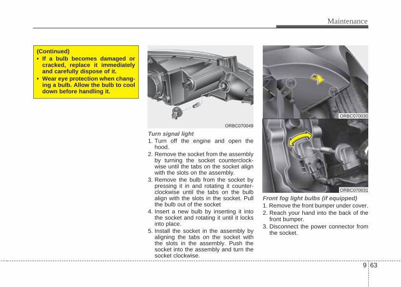
9 63
Maintenance
Turn signal light1. Turn off the engine and open the
hood.2. Remove the socket from the assembly
by turning the socket counterclock-wise until the tabs on the socket alignwith the slots on the assembly.
3. Remove the bulb from the socket bypressing it in and rotating it counter-clockwise until the tabs on the bulbalign with the slots in the socket. Pullthe bulb out of the socket
4. Insert a new bulb by inserting it intothe socket and rotating it until it locksinto place.
5. Install the socket in the assembly byaligning the tabs on the socket withthe slots in the assembly. Push thesocket into the assembly and turn thesocket clockwise.
Front fog light bulbs (if equipped)1. Remove the front bumper under cover.2. Reach your hand into the back of the
front bumper.3. Disconnect the power connector from
the socket.
ORBC070030
ORBC070031
(Continued)• If a bulb becomes damaged or
cracked, replace it immediatelyand carefully dispose of it.
• Wear eye protection when chang-ing a bulb. Allow the bulb to cooldown before handling it.
ORBC070049

Maintenance
649
4. Remove the bulb-socket from thehousing by turning the socket counterclockwise until the tabs on the socketalign with the slots on the housing.
5. Install the new bulb-socket into thehousing by aligning the tabs on thesocket with the slots in the housing.Push the socket into the housing andturn the socket clockwise.
6. Connect the power connector to thesocket.
7. Reinstall the front bumper undercover.

9 65
Maintenance
Side repeater light bulb replacementIf the light bulb does not operate, we rec-ommend that the system be checked byan authorized HYUNDAI dealer.
Rear combination light bulbreplacement(1) Stop and tail light(2) Rear turn signal lig ht(3) Back-up light
1. Open the trunk lid.2. Remove the service cover by pulling
out the service cover.
ORB070054/H ORBC070034ORBC070033

Maintenance
669
3. Remove the socket from the assemblyby turning the socket counterclock-wise until the tabs on the socket alignwith the slots on the assembly.
4. Remove the bulb from the socket bypressing it in and rotating it counter-clockwise until the tabs on the bulbalign with the slots in the socket. Pullthe bulb out of the socket.
5. Insert a new bulb by inserting it intothe socket and rotating it until it locksinto place.
6. Install the socket in the assembly byaligning the tabs on the socket withthe slots in the assembly. Push thesocket into the assembly and turn thesocket clockwise.
7. Install the service cover by putting itinto the service hole.
High mounted stop light bulbreplacement (if equipped)1. Open the trunk lid.2. Remove the socket by turning it coun-
terclockwise.3. Replace the bulb from the socket.4. Install the socket by turning it clock-
wise.
License plate light bulb replace-ment 1. Remove the trunk trim.2. Remove the socket by turning it coun-
terclockwise.3. Remove the bulb by pulling it straight
out.4. Install a new bulb.
ORBC070051
ORBC070043
ORBC070036
ORBC070041
ORBC070042
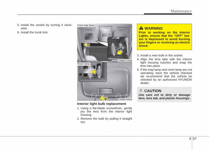
9 67
Maintenance
5. Install the socket by turning it clock-wise.
6. Install the trunk trim.
Interior light bulb replacement1. Using a flat-blade screwdriver, gently
pry the lens from the interior lighthousing.
2. Remove the bulb by pulling it straightout.
3. Install a new bulb in the socket.4. Align the lens tabs with the interior
light housing notches and snap thelens into place.
5. If the map lamp and room lamp are notoperating, have the vehicle checkedwe recommend that the vehicle bechecked by an authorized HYUNDAIdealer.
ORBI071065
ORB070064
Front map lamp
Room lamp
CAUTIONUse care not to dirty or damagelens, lens tab, and plastic housings.
WARNING Prior to working on the InteriorLights, ensure that the “OFF” but-ton is depressed to avoid burningyour fingers or receiving an electricshock.

Maintenance
689
Exterior careExterior general caution It is very important to follow the labeldirections when using any chemicalcleaner or polish. Read all warning andcaution statements that appear on thelabel.
Finish maintenanceWashing To help protect your vehicle’s finish fromrust and deterioration, wash it thoroughlyand frequently at least once a month withlukewarm or cold water. If you use your vehicle for off-road driv-ing, you should wash it after each off-road trip. Pay special attention to theremoval of any accumulation of salt, dirt,mud, and other foreign materials. Makesure the drain holes in the lower edges ofthe doors and rocker panels are keptclear and clean.Insects, tar, tree sap, bird droppings,industrial pollution and similar depositscan damage your vehicle’s finish if notremoved immediately. Even prompt washing with plain watermay not completely remove all thesedeposits. A mild soap, safe for use onpainted surfaces, may be used.After washing, rinse the vehicle thor-oughly with lukewarm or cold water. Donot allow soap to dry on the finish.
APPEARANCE CARE
CAUTION• Do not use strong soap, chemical
detergents or hot water, and donot wash the vehicle in directsunlight or when the body of thevehicle is warm.
• Be careful when washing the sidewindows of your vehicle.Especially, with high-pressurewater, water may leak through thewindows and wet the interior.
• To prevent damage to the plasticparts, do not clean with chemicalsolvents or strong detergents.
WARNING - Wet brakesAfter washing the vehicle, test thebrakes while driving slowly to see ifthey have been affected by water. Ifbraking performance is impaired,dry the brakes by applying themlightly while maintaining a slow for-ward speed.

9 69
Maintenance
WaxingWax the vehicle when water will nolonger bead on the paint.Always wash and dry the vehicle beforewaxing. Use a good quality liquid orpaste wax, and follow the manufacturer’sinstructions. Wax all metal trim to protectit and to maintain its luster.Removing oil, tar, and similar materialswith a spot remover will usually strip thewax from the finish. Be sure to re-waxthese areas even if the rest of the vehicledoes not yet need waxing.
Finish damage repair Deep scratches or stone chips in thepainted surface must be repairedpromptly. Exposed metal will quickly rustand may develop into a major repairexpense.
✽ NOTICEIf your vehicle is damaged and requiresany metal repair or replacement, be surethe body shop applies anti-corrosionmaterials to the parts repaired orreplaced.
CAUTION• Wiping dust or dirt off the body
with a dry cloth will scratch thefinish.
• Do not use steel wool, abrasivecleaners, or strong detergentscontaining highly alkaline orcaustic agents on chrome-platedor anodized aluminum parts. Thismay result in damage to the pro-tective coating and cause discol-oration or paint deterioration.
CAUTION• Water washing in the engine com-
partment including high pressurewater washing may cause the fail-ure of electrical circuits or engineand related part located in theengine compartment.
• Never allow water or other liquidsto come in contact with electri-cal/electronic components andair duct inside the vehicle as thismay damage them.
OJB037800

Maintenance
709
Bright-metal maintenance• To remove road tar and insects, use a
tar remover, not a scraper or othersharp object.
• To protect the surfaces of bright-metalparts from corrosion, apply a coating ofwax or chrome preservative and rub toa high luster.
• During winter weather or in coastalareas, cover the bright metal parts witha heavier coating of wax or preserva-tive. If necessary, coat the parts withnon-corrosive petroleum jelly or otherprotective compound.
Underbody maintenanceCorrosive materials used for ice andsnow removal and dust control may col-lect on the underbody. If these materialsare not removed, accelerated rusting canoccur on underbody parts such as thefuel lines, frame, floor pan and exhaustsystem, even though they have beentreated with rust protection.Thoroughly flush the vehicle underbodyand wheel openings with lukewarm orcold water once a month, after off-roaddriving and at the end of each winter.Pay special attention to these areasbecause it is difficult to see all the mudand dirt. It will do more harm than goodto wet down the road grime withoutremoving it. The lower edges of doors,rocker panels, and frame members havedrain holes that should not be allowed toclog with dirt; trapped water in theseareas can cause rusting.
WARNINGAfter washing the vehicle, test thebrakes while driving slowly to see ifthey have been affected by water. Ifbraking performance is impaired,dry the brakes by applying themlightly while maintaining a slow for-ward speed.

9 71
Maintenance
Aluminum wheel maintenance The aluminum wheels are coated with aclear protective finish.• Do not use any abrasive cleaner, pol-
ishing compound, solvent, or wirebrushes on aluminum wheels. Theymay scratch or damage the finish.
• Use only a mild soap or neutral deter-gent, and rinse thoroughly with water.Also, be sure to clean the wheels afterdriving on salted roads. This helps pre-vent corrosion.
• Avoid washing the wheels with high-speed car wash brushes.
• Do not use any acid detergent. It maydamage and corrode the aluminumwheels coated with a clear protectivefinish.
Corrosion protectionProtecting your vehicle from corrosionBy using the most advanced design andconstruction practices to combat corro-sion, we produces cars of the highestquality. However, this is only part of thejob. To achieve the long-term corrosionresistance your vehicle can deliver, theowner's cooperation and assistance isalso required.
Common causes of corrosionThe most common causes of corrosionon your car are:• Road salt, dirt and moisture that is
allowed to accumulate underneath thecar.
• Removal of paint or protective coatingsby stones, gravel, abrasion or minorscrapes and dents which leave unpro-tected metal exposed to corrosion.
High-corrosion areasIf you live in an area where your car isregularly exposed to corrosive materials,corrosion protection is particularly impor-tant. Some of the common causes ofaccelerated corrosion are road salts,dust control chemicals, ocean air andindustrial pollution.
Moisture breeds corrosionMoisture creates the conditions in whichcorrosion is most likely to occur. Forexample, corrosion is accelerated byhigh humidity, particularly when temper-atures are just above freezing. In suchconditions, the corrosive material is keptin contact with the car surfaces by mois-ture that is slow to evaporate.Mud is particularly corrosive because it isslow to dry and holds moisture in contactwith the vehicle. Although the mudappears to be dry, it can still retain themoisture and promote corrosion.High temperatures can also acceleratecorrosion of parts that are not properlyventilated so the moisture can be dis-persed. For all these reasons, it is par-ticularly important to keep your car cleanand free of mud or accumulations ofother materials. This applies not only tothe visible surfaces but particularly to theunderside of the car.
Maintenance
729
To help prevent corrosionYou can help prevent corrosion from get-ting started by observing the following:
Keep your car cleanThe best way to prevent corrosion is tokeep your car clean and free of corrosivematerials. Attention to the underside ofthe car is particularly important.
• If you live in a high-corrosion area —where road salts are used, near theocean, areas with industrial pollution,acid rain, etc.—, you should take extracare to prevent corrosion. In winter,hose off the underside of your car atleast once a month and be sure toclean the underside thoroughly whenwinter is over.
• When cleaning underneath the car,give particular attention to the compo-nents under the fenders and otherareas that are hidden from view. Do athorough job; just dampening the accu-mulated mud rather than washing itaway will accelerate corrosion ratherthan prevent it. Water under high pres-sure and steam are particularly effec-tive in removing accumulated mud andcorrosive materials.
• When cleaning lower door panels,rocker panels and frame members, besure that drain holes are kept open sothat moisture can escape and not betrapped inside to accelerate corrosion.
Keep your garage dryDon't park your car in a damp, poorlyventilated garage. This creates a favor-able environment for corrosion. This isparticularly true if you wash your car inthe garage or drive it into the garagewhen it is still wet or covered with snow,ice or mud. Even a heated garage cancontribute to corrosion unless it is wellventilated so moisture is dispersed.
Keep paint and trim in good conditionScratches or chips in the finish should becovered with "touch-up" paint as soon aspossible to reduce the possibility of cor-rosion. If bare metal is showing through,the attention of a qualified body and paintshop is recommended.
Bird droppings : Bird droppings are high-ly corrosive and may damage paintedsurfaces in just a few hours. Alwaysremove bird droppings as soon as possi-ble.
Don't neglect the interiorMoisture can collect under the floor matsand carpeting to cause corrosion. Checkunder the mats periodically to be sure thecarpeting is dry. Use particular care ifyou carry fertilizers, cleaning materials orchemicals in the car.These should be carried only in propercontainers and any spills or leaks shouldbe cleaned up, flushed with clean waterand thoroughly dried.
9 73
Maintenance
Interior careInterior general precautions Prevent caustic solutions such as per-fume and cosmetic oil from contactingthe dashboard because they may causedamage or discoloration. If they do con-tact the dashboard, wipe them off imme-diately. See the instructions that followfor the proper way to clean vinyl.
Cleaning the upholstery and interiortrim Vinyl Remove dust and loose dirt from vinylwith a whisk broom or vacuum cleaner.Clean vinyl surfaces with a vinyl cleaner.
Fabric Remove dust and loose dirt from fabricwith a whisk broom or vacuum cleaner.Clean with a mild soap solution recom-mended for upholstery or carpets.Remove fresh spots immediately with afabric spot cleaner. If fresh spots do notreceive immediate attention, the fabriccan be stained and its color can beaffected. Also, its fire-resistant propertiescan be reduced if the material is notproperly maintained.
Cleaning the lap/shoulder belt web-bing Clean the belt webbing with any mildsoap solution recommended for cleaningupholstery or carpet. Follow the instruc-tions provided with the soap. Do notbleach or re-dye the webbing becausethis may weaken it.
Cleaning the interior window glass If the interior glass surfaces of the vehi-cle become fogged (that is, covered withan oily, greasy or waxy film), they shouldbe cleaned with glass cleaner. Follow thedirections on the glass cleaner container.
CAUTIONUsing anything but recommendedcleaners and procedures may affectthe fabric’s appearance and fire-resistant properties.
CAUTIONDo not scrape or scratch the insideof the rear window. This may resultin damage to the rear windowdefroster grid.
CAUTIONNever allow water or other liquidsto come in contact with electrical/electronic components inside thevehicle as this may damage them.
CAUTIONWhen cleaning leather products(steering wheel, seats etc.), useneutral detergents or low alcoholcontent solutions. If you use highalcohol content solutions oracid/alkaline detergents, the colorof the leather may fade or the sur-face may get stripped off.

Maintenance
749
EMISSION CONTROL SYSTEM (IF EQUIPPED)The emission control system of yourvehicle is covered by a written limitedwarranty. Please see the warranty infor-mation contained in the Service Passportin your vehicle.Your vehicle is equipped with an emis-sion control system to meet all applicableemission regulations.There are three emission control sys-tems, as follows.
(1) Crankcase emission control system(2) Evaporative emission control system(3) Exhaust emission control system
In order to assure the proper function ofthe emission control systems, it is rec-ommended that you have your carinspected and maintained by an author-ized HYUNDAI dealer in accordance withthe maintenance schedule in this manu-al.
1. Crankcase emission controlsystem
The positive crankcase ventilation sys-tem is employed to prevent air pollutioncaused by blow-by gases being emittedfrom the crankcase. This system sup-plies fresh filtered air to the crankcasethrough the air intake hose. Inside thecrankcase, the fresh air mixes with blow-by gases, which then pass through thePCV valve into the induction system.
2. Evaporative emission controlsystem
The Evaporative Emission ControlSystem is designed to prevent fuelvapors from escaping into the atmos-phere.

9 75
Maintenance
CanisterFuel vapors generated inside the fueltank are absorbed and stored in theonboard canister. When the engine isrunning, the fuel vapors absorbed in thecanister are drawn into the surge tankthrough the purge control solenoid valve.
Purge Control Solenoid Valve (PCSV)The purge control solenoid valve is con-trolled by the Engine Control Module(ECM); when the engine coolant temper-ature is low during idling, the PCSV clos-es so that evaporated fuel is not takeninto the engine. After the engine warms-up during ordinary driving, the PCSVopens to introduce evaporated fuel to theengine.
3. Exhaust emission control system
The Exhaust Emission Control System isa highly effective system which controlsexhaust emissions while maintaininggood vehicle performance.
Vehicle modifications • This vehicle should not be modified.
Modification of your vehicle couldaffect its performance, safety or dura-bility and may even violate govern-mental safety and emissions regula-tions.In addition, damage or performanceproblems resulting from any modifica-tion may not be covered under warran-ty.
• If you use unauthorized electricdevices, it may cause the vehicle tooperate abnormally, wire damage, bat-tery discharge and fire. For your safe-ty, be careful not to damage.
Engine exhaust gas precautions (car-bon monoxide) • Carbon monoxide can be present with
other exhaust fumes. Therefore, if yousmell exhaust fumes of any kind insideyour vehicle, have it inspected andrepaired immediately. If you ever sus-pect exhaust fumes are coming intoyour vehicle, drive it only with all thewindows fully open. Have your vehiclechecked and repaired immediately.
WARNING - ExhaustEngine exhaust gases contain car-bon monoxide (CO). Though color-less and odorless, it is dangerousand could be lethal if inhaled.Follow the instructions on thispage to avoid CO poisoning.

Maintenance
769
• Do not operate the engine in confinedor closed areas (such as garages) anymore than what is necessary to movethe vehicle in or out of the area.
• When the vehicle is stopped in anopen area for more than a short timewith the engine running, adjust theventilation system (as needed) to drawoutside air into the vehicle.
• Never sit in a parked or stopped vehi-cle for any extended time with theengine running.
• When the engine stalls or fails to start,excessive attempts to restart theengine may cause damage to theemission control system.
Operating precautions for catalyticconverters (if equipped)
Your vehicle is equipped with a catalyticconverter emission control device.Therefore, the following precautionsmust be observed:• Make sure to refuel your vehicle
according to the "Fuel requirements"suggested in section 1.
• Do not operate the vehicle when thereare signs of engine malfunction, suchas misfire or a noticeable loss of per-formance.
• Do not misuse or abuse the engine.Examples of misuse are coasting withthe ignition off and descending steepgrades in gear with the ignition off.
• Do not operate the engine at high idlespeed for extended periods (5 minutesor more).
• Do not modify or tamper with any partof the engine or emission control sys-tem. engine or emission control sys-tem. We recommend that the systembe inspected by an authorizedHYUNDAI dealer.
• Avoid driving with a extremly low fuellevel. Running out of fuel could causethe engine to misfire, damaging thecatalytic converter.
Failure to observe these precautionscould result in damage to the catalyticconverter and to your vehicle.Additionally, such actions could void yourwarranties.
WARNING - Fire• A hot exhaust system can ignite
flammable items under your vehi-cle. Do not park, idle, or drive thevehicle over or near flammableobjects, such as grass, vegeta-tion, paper, leaves, etc.
• The exhaust system and catalyticsystem are very hot while theengine is running or immediatelyafter the engine is turned off. Keepaway from the exhaust systemand catalytic, you may get burned.Also, do not remove the heat sinkaround the exhaust system, donot seal the bottom of the vehicleor do not coat the vehicle for cor-rosion control. It may present afire risk under certain conditions.

9 77
Maintenance
Diesel Particulate Filter (if equipped)The Diesel Particulate Filter (DPF) sys-tem removes the soot emitted from thevehicle.Unlike a disposable air filter, the DPFsystem automatically burns (oxidizes)and removes the accumulated sootaccording to the driving condition. Inother words, the active burning by enginecontrol system and high exhaust gastemperature caused by normal/high driv-ing condition burns and removes theaccumulated soot.However, if the vehicle continues to bedriven at low speed for long time, theaccumulated soot may not be automati-cally removed because of low exhaustgas temperature. In this particular case,the amount of soot is out of detectionlimit, the soot oxidation process byengine control system may not happenand the malfunction indicator light mayblink.When the malfunction indicator lightblinks, it may stop blinking by driving thevehicle at more than 60km/h (37 mph) orat more than second gear with 1500 ~2000 engine rpm for a certain time (forabout 25 minutes).
If the malfunction indicator light contin-ues to blink in spite of the procedure, werecommend that the system be checkedby an authorized HYUNDAI dealer.If you continue to drive with the malfunc-tion indicator light blinking for a longtime, the DPF system can be damagedand fuel consumption can be worsen.
CAUTION - Diesel Fuel (if equipped with DPF)
It is recommended to use the regu-lated automotive diesel fuel fordiesel vehicle equipped with theDPF system.If you use diesel fuel including highsulfur (more than 50 ppm sulfur)and unspecified additives, it cancause the DPF system to be dam-aged and white smoke can be emit-ted.

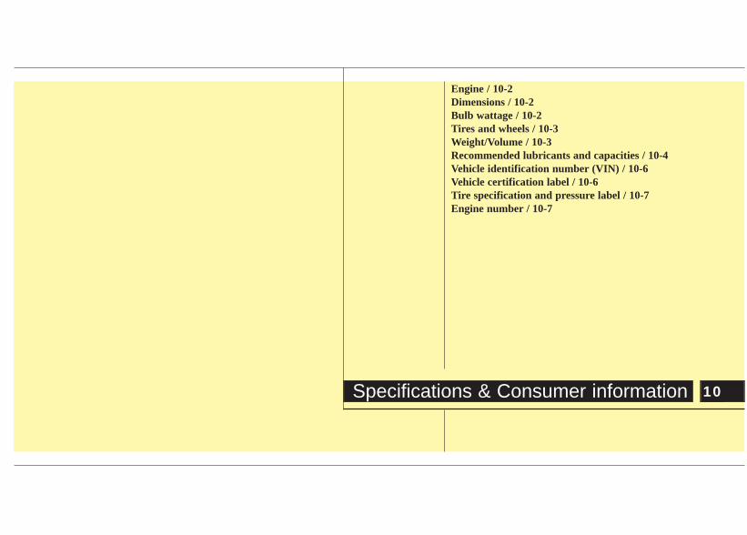
Engine / 10-2Dimensions / 10-2Bulb wattage / 10-2Tires and wheels / 10-3Weight/Volume / 10-3Recommended lubricants and capacities / 10-4Vehicle identification number (VIN) / 10-6Vehicle certification label / 10-6Tire specification and pressure label / 10-7Engine number / 10-7
10 Specifications & Consumer information
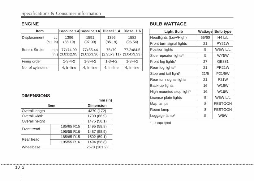
Specifications & Consumer information
210
ENGINE BULB WATTAGE
* : If equipped
Item Dimension Overall length 4370 (172)Overall width 1700 (66.9)Overall height 1475 (58.1)
Front tread185/65 R15 1495 (58.9)195/55 R16 1487 (58.5)
Rear tread185/65 R15 1502 (59.1)195/55 R16 1494 (58.8)
Wheelbase 2570 (101.2)
Item Gasoline 1.4 Gasoline 1.6 Diesel 1.4 Diesel 1.6
Displacement cc(cu. in)
1396(85.19)
1591(97.09)
1396(85.19)
1582(96.54)
Bore x Stroke mm(in.)
77x74.99(3.03x2.95)
77x85.44(3.03x3.36)
75x79(2.95x3.11)
77.2x84.5(3.04x3.33)
Firing order 1-3-4-2 1-3-4-2 1-3-4-2 1-3-4-2
No. of cylinders 4, In-line 4, In-line 4, In-line 4, In-line
DIMENSIONS
Light Bulb Wattage Bulb type
Headlights (Low/High) 55/60 H4 L/L
Front turn signal lights 21 PY21W
Position lights 5 W5W L/L
Side repeater lights* 5 WY5W
Front fog lights* 27 GE881
Rear fog lights* 21 PR21W
Stop and tail light* 21/5 P21/5W
Rear turn signal lights 21 P21W
Back-up lights 16 W16W
High mounted stop light* 16 W16W
License plate lights 5 W5W L/L
Map lamps 8 FESTOON
Room lamp 8 FESTOON
Luggage lamp* 5 W5W
mm (in)

10 3
Specifications & Consumer information
TIRES AND WHEELS
Item Tire size Wheel sizeInflation pressure bar (psi, kPa)
Wheel lug nut torquekg•m (lb•ft, N•m)
Normal load Maximum loadFront Rear Front Rear
Full size tire185/65 R15 5.5Jx15
2.2 (32,220)
2.2 (32,220)
2.2 (32,220)
2.2 (32,220)
9~11 (65~79, 88~107)
195/55 R16 6.0Jx16
WEIGHT/VOLUME
Item Gasoline 1.4 Gasoline 1.6 Diesel 1.4 Diesel 1.6
Gross vehicle weight kg (lbs.)
1,560 (3,439) 1,560 (3,439) 1650 (3637) 1,650 (3,637)
Luggage volume l (cu ft)
460 (16.2) 460 (16.2) 460(16.2) 460 (16.2)

Specifications & Consumer information
410
RECOMMENDED LUBRICANTS AND CAPACITIES
Lubricant Volume ClassificationEngine oil *1 *2
(drain and refill)GasolineEngine
1.4L/1.6L 3.3 lAPI Service SL or above *3,
ILSAC GF-4 or above
Diesel Engine 1.4L/1.6L 5.3 lAPI Service CH-4, ACEA B4 (WithoutDPF), ACEA C3 (With DPF) or above
Engine oil consumptionNormal driving condition MAX. 1 l /1500 km -
Severe driving condition MAX. 1 l /1000 km -
Manual transaxle fluidGasolineEngine
1.4L/1.6L 1.9 l ~ 2.0 lAPI Service GL-4 (SAE 75W-85)
Diesel Engine 1.4L/1.6L 1.9 l ~ 2.0 l
Automatic transaxle fluidGasolineEngine
1.6L 6.8 lDIAMOND ATF SP-III, SK ATF SP-III
Diesel Engine 1.6L 6.6 l
Coolant GasolineEngine
1.4L/1.6L 5.3 l MIXTURE, Antifreeze with water (Ethyleneglycol base coolant for aluminum radiator)
Diesel Engine 1.4L/1.6L 6.3 l
Brake/Clutch fluid 0.7~0.8 l FMVSS116 DOT-3 or DOT-4
Fuel 43 l -
To help achieve proper engine and powertrain performance and durability, use only lubricants of the proper quality. The correctlubricants also help promote engine efficiency that results in improved fuel economy.These lubricants and fluids are recommended for use in your vehicle.
*1: Refer to the recommended SAE viscosity numbers on the next page.*2: Engine oils labeled Energy Conserving Oil are now available. Along with other additional benefits, they contribute to fuel econ-
omy by reducing the amount of fuel necessary to overcome engine friction. Often, these improvements are difficult to measurein everyday driving, but in a year’s time, they can offer significant cost and energy savings.
*3: Use the engine oils approved by Hyundai Motor India Ltd. Consult an authorized HYUNDAI dealer for details.

10 5
Specifications & Consumer information
Recommended SAE viscositynumber
Engine oil viscosity (thickness) has aneffect on fuel economy and cold weatheroperating (engine start and engine oilflowability). Lower viscosity engine oilscan provide better fuel economy and coldweather performance, however, higherviscosity engine oils are required for sat-isfactory lubrication in hot weather. Using oils of any viscosity other thanthose recommended could result inengine damage.
When choosing an oil, consider therange of temperature your vehicle will beoperated in before the next oil change.Proceed to select the recommended oilviscosity from the chart.
CAUTIONAlways be sure to clean the areaaround any filler plug, drain plug, ordipstick before checking or drain-ing any lubricant. This is especiallyimportant in dusty or sandy areasand when the vehicle is used onunpaved roads. Cleaning the plugand dipstick areas will prevent dirtand grit from entering the engineand other mechanisms that couldbe damaged.
Temperature Range for SAE Viscosity Numbers
Temperature°C
(°F)-30 -20 -10 0 10 20 30 40 50
-10 0 20 40 60 80 100 120
DieselEngine Oil 5W-30
15W-40
10W-30
0W-30
*1: For better fuel economy, it is recommended to use the engine oil of a viscosity grade SAE5W-20 (API SM/ILSAC GF-4). However, select the proper engine oil using the engine oil vis-cosity chart.
Gasoline Engine Oil *1
20W-50
10W-30
15W-40
5W-20, 5W-30

Specifications & Consumer information
610
VEHICLE IDENTIFICATION NUMBER (VIN)
The vehicle identification number (VIN) isthe number used in registering your carand in all legal matters pertaining to itsownership, etc.The number is punched on floor underthe driver seat. To check the numberremove the cover.
The vehicle certification label attachedon the driver’s (or front passenger’s) sidecenter pillar gives the vehicle identifica-tion number (VIN).
VEHICLE CERTIFICATIONLABEL
ORBC080001
■ Type A
ORB080003
■ Type A

10 7
Specifications & Consumer information
The tires supplied on your new vehicleare chosen to provide the best perform-ance for normal driving.The tire label located on the driver's sidecenter pillar gives the tire pressures rec-ommended for your car.
The engine number is stamped on theengine block as shown in the drawing.
TIRE SPECIFICATION ANDPRESSURE LABEL
ENGINE NUMBER
ORBI071017
ORBC080004
ORB080004
■ Gasoline Engine
■ Diesel Engine

IIndex

Index
2I
Air bag - supplemental restraint system........................5-23Air cleaner ....................................................................9-31Appearance care ............................................................9-68Audio system ................................................................6-97Automatic climate control system ................................6-80Automatic transaxle ......................................................7-17Automatic transaxle fluid ..............................................9-27
Battery ..........................................................................9-37Before driving..................................................................7-3Brake system..................................................................7-23Brake/clutch fluid ..........................................................9-26Bulb wattage ..................................................................10-2Brake system..................................................................5-23
Child restraint system ....................................................5-18Climate control air filter ................................................9-33
Defroster ........................................................................6-70Dimensions ....................................................................10-2Door locks ......................................................................6-12
Economical operation ....................................................7-30Emergency starting ..........................................................8-5Emission control system ................................................9-74Emission Warranty ..........................................................2-5Engine ............................................................................10-2Engine compartment ........................................................4-6Engine compartment ........................................................9-2Engine coolant ................................................................9-23Engine number................................................................10-7Engine oil ........................................................................9-21Engine Start/Stop button ..................................................7-8Explanation of scheduled maintenance items ................9-18
Fuel filler lid ..................................................................6-24Fuel filter ........................................................................9-30Fuel requirements ............................................................3-3Fuses ..............................................................................9-50
Hazard warning flasher ..................................................6-60Hood................................................................................6-22How to use this manual ....................................................3-2Hyundai New Vehicle Warranty ......................................2-2
A
B
C
D
E
F
H

I 3
Index
If the engine does not start................................................8-4If the engine overheats......................................................8-7If you have a flat tire ........................................................8-8In case of an emergency while driving ............................8-3Indicator symbols on the instrument cluster ....................3-7Instrument cluster ..........................................................6-33Instrument panel overview ..............................................4-4Interior features ..............................................................6-92Interior light ....................................................................6-68Interior overview ..............................................................4-2
Key....................................................................................7-5Keys ..................................................................................6-3
Light bulbs ......................................................................9-61Lighting ..........................................................................6-61
Maintenance Record Sheet ..............................................1-2Maintenance services ........................................................9-8Manual climate control system ......................................6-71
Manual transaxle ............................................................7-14Mirrors ............................................................................6-29
Owner maintenance ..........................................................9-5
Parking brake ..................................................................9-29Parts Replacement Warranty ............................................2-3
Rear parking assist system..............................................6-56Rearview camera ............................................................6-59Recommended lubricants and capacities ........................10-4Remote keyless entry ........................................................6-9Road warning....................................................................8-2
Scheduled maintenance service ........................................9-7Seat belts ..........................................................................5-9Seats ..................................................................................5-2Smart key ..........................................................................6-5Special driving conditions ..............................................7-32Steering wheel ................................................................6-27
I
K
L
M
O
P
R
S

Index
4I
Storage compartment ......................................................6-90
Tire specification and pressure label ..............................10-7Tires and wheels ............................................................10-3Tires and wheels ............................................................9-40Towing ............................................................................8-14Trunk ..............................................................................6-16
Vehicle break-in process ..................................................3-6Vehicle certification label ..............................................10-6Vehicle identification number (VIN) ............................10-6Vehicle weight ................................................................7-39
Washer fluid....................................................................9-29Weight/Volume ..............................................................10-3Windows ........................................................................6-18Windshield defrosting and defogging ............................6-87Winter driving ................................................................7-36Wiper blades ..................................................................9-35Wipers and washers ........................................................6-66
T
V
W