operation guide camper - hobby caravan · dear camper, congratulations on the purchase of your new...
TRANSCRIPT

Operation Guide Camper
Version 01/2011
GB

Dear Camper,
Congratulations on the purchase of your new HOBBY camper. The trust you have placed in us is both an incentive and an obligation to continuously implement new ideas, technical innovations and fine touches to make our campers even better. Our fully fitted and highly sophisticated models enable us to offer you the perfect setting for the most enjoyable days of the year.
Please read this manual carefully, even if you have been driving a camper for a longer period of time. It will help you to avoid operating errors and damage to the vehicle and its equipment. Correct handling of all technical details will increase your driving comfort and maintain the value of your camper.
If this user manual should be unable to provide the required assistance, a close, pan-European net-work of dealers is available for further help. Take advantage of your authorised dealer's experience and technical knowledge - we recommend speaking to him in detail before taking your first trip with your HOBBY camper.
We wish you and your fellow travellers many enjoyable trips and hope you will always have a safe journey with your new HOBBY camper.
YourHOBBY Camper PlantIng. Harald Striewski GmbH

Table of Contents
1 Introduction ..........................................................................................................................01-1 1.1 General information .......................................................................................................01-1 1.2 Markings in these operation instructions ......................................................................01-2
2 Safety ....................................................................................................................................02-1 2.1 General information .......................................................................................................02-1 2.2 Before the drive .............................................................................................................02-2 2.3 Loading ..........................................................................................................................02-4 2.4 Handling Performance ...................................................................................................02-6 2.5 After the drive ................................................................................................................02-8 3 Undercarriage and vehicle registration .............................................................................03-1 3.1 General information .......................................................................................................03-1 3.2 Drawbars/Longitudinal beams ......................................................................................03-1 3.3 Safety coupling WS 3000 ..............................................................................................03-2 3.4 Front landing wheel .......................................................................................................03-5 3.5 Locking brake facilities ..................................................................................................03-6 3.6 Overrunning equipment and wheel brakes ....................................................................03-7 3.7 Rotating stanchions .......................................................................................................03-8 3.8 Vehicle registration ........................................................................................................03-9 3.9 General inspection .........................................................................................................03-9 3.10 Fit for a Speed of 100 km/h .........................................................................................03-10 3.11 Definition of mass ........................................................................................................03-11
4 Wheels, tires ........................................................................................................................04-1 4.1 Tires ...............................................................................................................................04-1 4.2 Tire pressure ..................................................................................................................04-1 4.3 Profile depth and age of tires ........................................................................................04-2 4.4 Rims ...............................................................................................................................04-3 4.5 Changing the tire ...........................................................................................................04-4
5 Exterior structure .................................................................................................................05-1 5.1 Ventilation and De-aerating ...........................................................................................05-1 5.2 Entry door ......................................................................................................................05-3 5.3 Service flap ....................................................................................................................05-5 5.4 Gas-bottle container flap ...............................................................................................05-6 5.5 Toilet flap .......................................................................................................................05-6 5.6 Roof ...............................................................................................................................05-7 5.7 Guide rail for outer tent and skirting .............................................................................05-7 5.8 Bicycle carrier ................................................................................................................05-9 5.9 Roof awning...................................................................................................................05-9
6 Interior structure ..................................................................................................................06-1 6.1 Doors, flaps and drawers ..............................................................................................06-1 6.2 Pivoting TV cabinet .......................................................................................................06-3 6.3 Extendable media shelf .................................................................................................06-4 6.4 TV mount .......................................................................................................................06-5 6.5 Tables ............................................................................................................................06-5 6.6 Conversion of seats and beds .......................................................................................06-7 6.7 Children's beds..............................................................................................................06-9 6.8 Windows ........................................................................................................................06-9 6.9 Roof bonnets ...............................................................................................................06-12
7 Installation of electrical devices .........................................................................................07-1 7.1 Safety tips ......................................................................................................................07-1

7.2 Control panel .................................................................................................................07-2 7.3 Electrical supply ..........................................................................................................07-11 7.4 Electrical system..........................................................................................................07-14 7.5 External circuit diagram ...............................................................................................07-16 7.6 Contact plan for the light control system ....................................................................07-17 7.7 Special Lighting ...........................................................................................................07-18
8 Water .....................................................................................................................................08-1 8.1 General information .......................................................................................................08-1 8.2 Tanks .............................................................................................................................08-2 8.3 Water supply ..................................................................................................................08-3 8.4 Water flushing toilet ......................................................................................................08-6
9 Gas system ...........................................................................................................................09-1 9.1 General safety rules for the use of liquid gas facilities ..................................................09-1 9.2 Gas supply .....................................................................................................................09-3 9.3 Gas socket, external ......................................................................................................09-5
10 Built-in devices .....................................................................................................................10-1 10.1 General information .......................................................................................................10-1 10.2 Hot-air heating ...............................................................................................................10-2 10.3 Electric auxiliary heating ................................................................................................10-5 10.4 Electrical floor heating ...................................................................................................10-6 10.5 Hot-water heating system .............................................................................................10-7 10.6 Boiler ...........................................................................................................................10-13 10.7 Refrigerator ..................................................................................................................10-15 10.8 Gas cooker ..................................................................................................................10-18 10.9 Fume hood ..................................................................................................................10-20 10.10 Oven ...........................................................................................................................10-20 10.11 Microwave ..................................................................................................................10-22 11 Accessories ..........................................................................................................................11-1 12 Maintenance and upkeep ....................................................................................................12-1 12.1 Maintenance ..................................................................................................................12-1 12.2 Drawgear .......................................................................................................................12-2 12.3 Brakes............................................................................................................................12-4 12.4 Changing the taillight bulbs ...........................................................................................12-5 12.5 Ventilation ......................................................................................................................12-6 12.6 Upkeep ..........................................................................................................................12-6 12.7 Winter Lay Up for the Camper .....................................................................................12-11 12.8 Winter Operation .........................................................................................................12-13
13 Waste disposal and environmental protection ..................................................................13-1 13.1 The environment and mobile travel ...............................................................................13-1
14 Technical data ......................................................................................................................14-1 14.1 Tire pressure values .......................................................................................................14-1 14.2 Weights in accordance with 97/27/EG ..........................................................................14-1 14.3 Basic equipment ............................................................................................................14-3 14.4 Technical data ................................................................................................................14-4 14.5 Possibilities for increasing loads ....................................................................................14-6 14.6 Tires and Rims ...............................................................................................................14-8 14.7 Lighting ........................................................................................................................14-10 14.8 Moulding ......................................................................................................................14-11 Index ........................................................................................................................................Ix-1

01-1
Our campers are continuously being further de-veloped. Please understand that we reserve the right to make changes to their equipment, shape and technology. Therefore, HOBBY shall not be liable for any claims arising from the contents of this handbook. The equipment used at the time of printing is described in this handbook and should be transferred accordingly to the layouts of all the different camper variations. Please understand that we cannot describe all of the individual variations. Your dealer will be pleased to answer any special questions regarding the equipment and technology of your camper.
Your HOBBY camper has been built in accor-dance with the latest technology and recognised safety regulations. Despite all of these safety measures, it is possible that people may be hurt or the camper damaged if the safety instructions in this handbook and the warnings posted on adhesive labels in the camper are not followed.
1. Introduction
1.1 General information
Before the first tripYou should certainly familiarize yourself tho-roughly with the contents of this handbook; it is much more than a reference book.
Fill out the guarantee cards for the built-in appli-ances in the separate instructions, and send the guarantee cads to the respective manufacturers. In doing so, you secure your right to a guarantee for all devices.
HOBBY grants a 5-year guarantee on the watertightness of the camper in accordance with guarantee condi-tions. When you accept the vehicle you will receive the guarantee book-let, "Five-Year Guarantee on Water-tightness" from your HOBBY dealer.
Annual leak checks are not free of charge. Warning: If no leak inspection is performed, your right to the 5-year guarantee loses its validity.

01-2
1.2 Markings in these operation instructions
Markings in these operation instructions
The handbook explains the camper as follows
Texts and illustrationsThe texts which accompany illustrations are found directly to the right of the illustrations. De-tails in illustrations (here: entry door) are marked with position numbers j.
Lists- Lists are based on key points and are pre- ceded by a dash.
Procedural guidelines• Procedural guidelines are also based on key points and begin with a round sentence opener.
Guidelines
Guidelines point out important details which ensure the trouble-free func-tion of the camper and its equipment. Please bear in mind that various mo-dels have different equipment; there-fore, varying descriptions are possible.
Warnings
Warnings point out dangers which, if they are not followed, could cause damage to equipment and/or injury to persons.
Environmental tips
Environmental tips show possible ways to reduce strain on the environ- ment.
1


02-1
Warnings and information labels are attached both inside and outside the vehicle. These are meant for your safety and may not be removed.
Keys The following keys are provided with the camper:- Two keys which fit into the following locks: - entry door, - service flaps, - toilet flap. - gas-bottle container lid - fresh-water tank lid
Emergency equipmentTo be prepared for an emergency, you need at lest three basic items of rescue equipment (first aid kit, warning triangle and fire extinguisher) which you should carry at all times and know how to use.
- frist aid kit- warning triangle- high-visibility vest
Fire prevention measures• Never leave children unattended in the vehicle. • Keep flammable materials away from all hea-
ting and cooking appliances. • Changes to the electrical system, gas system
or built-in devices may only be carried out by professional, authorised workshops.
• Place a fire extinguisher at the main entry door.
• Ensure that everyone is familiar with the guide-lines on the fire extinguisher.
• Place a fire cover near the gas cooker. • Keep all escape routes clear. • Ensure that everyone is familiar with the fire
prevention measures on site.
2. Safety 2.1 General information
100 m
02-2
ExteriorGo around the carriage and prepare for the drive as follows:
Preparation of the vehicle• The camper must be hitched properly (see guidelines for the safety hitch WS3000).• Release the handbrake of the camper and attach the contact-breaking cable to the cou- pling ball of the base vehicle.• Tighten the tire bolts after driving the first 50 km.• Plug the 13-channel plug in the socket of the base vehicle.• Inspect the vehicle lighting.• Turn the winding stanchions and the front landing wheel upward and secure them.• Close gas bottles (heating is forbidden while driving).• Empty the waste water tank.• Close gas bottle compartment.• Adjust outer mirrors on base vehicle.• Check camper's tire pressure (see tire pressure table).• Close all windows.• Close the service flaps.• Close and firmly lock roof bonnet.• Shut off the light on the outer tent.• Close and secure entry door.• If necessary, pull the electrical cord to the 230 V mains supply out of the exterior socket.• If necessary, pull the television antenna in- ward as far as possible or fold over the satellite dish.
Fighting a fire• Evacuate all passengers immediately.• Close the main shut-off valve on the gas bottle as well as the shut-off valves on gas- powered appliances.• Shut off the electrical supply• Sound alarm and call the fire department.• Only fight the fire yourself if this is possible without risk.
2.2 Before the driveAs the owner and driver, you are responsible for the condition of your vehicle. Therefore, you must note the following points:

02-3
Staying in the camper during the drive is prohibited by law!
• If necessary, secure the roof load and lash it to prevent slippage.• If necessary, secure all bicycles and lash them to prevent slippage, ensuring that they do not cover any lighting equipment. • In winter, the roof must be free of snow and ice before you begin to drive.
InteriorYou must also prepare the interior of the vehicle
Preparing the interior:• Sort all loose objects and store them in their respective compartments.• Store heavy and / or voluminous objects (e.g. radio, outer tent, beverage cases) safely before you start your journey, securing them to prevent them from shifting.• If necessary, redirect refrigerator to 12-volt operation.• Shut off all interior lighting.• Ensure that all fluids, including those in refrig- erator, are secured to prevent leakage.• Close main valve on gas container and quick- close valves on all gas-powered appliances.• Close all doors (incl. refrigerator door), drawers and flaps tightly.• Lock the central lock on the kitchen drawers.• Latch the sliding door.• Lower table and secure it.• Secure the extendable media shelf, media oval or TV mount.

02-4
2.3 LoadingRules for loading:• Spread the load evenly between the left and right-hand side of the camper. Heavy or bulky objects belong in the lower storage compart- ments and near the axle.• If your camper has a tandem axle: distribute the centre of weight between the two axles.• Never focus the load in the camper to the rear (danger of swinging back and forth).• Heavy objects should be stowed securely to prevent them from slipping.• Lighter objects (clothing) should be stowed in the wall cupboards.• You may not always be able to follow the re- recommended stowing arrangement, because storage possibilities are distributed throug hout the entire interior of the camper. If ne- cessary, stow heavy objects in the base vehicle.• Store baggage in the interior in cupboards and storage compartments.• Secure doors and flaps.• Check the technically permissible maximum weight and the axle load(s) after you have finished loading.
The gross vehicle weight rating in- dicated in the vehicle documents as well as the permitted drawbar load may not be exceeded. Also note the permissible drawbar load of your base vehicle.
The lower the camper's centre of gra-vity, the better its driving performance and response in curves.
The permissible maximum weight and the permissible drawbar load entered in the vehicle's registration documents may not be exceeded.

02-5
Drawbar load
You will only achieve optimum driving stability and decisively increase your safety on the road if the drawbar load has been properly adjusted for your combination of base vehicle and the cam-per being pulled. The drawbar load indicates the power the camper's drawbar exerts on the car's clutch.
Rules for the drawbar load:• Set the drawbar load correctly! You can, for
example, use normal bathroom scales: use a strip of wood (approx. 400 mm long) to po-sition them vertically under the coupling jaw. It may also be possible to roughly estimate the drawbar load by means of the drawbar load scales m integrated in the front landing wheel, whereby the drawbar of the camper must be in a horizontal position.
• Always check the drawbar load before you start to drive!• The specified drawbar load (see handbook or type plate) and the permissible overall mass of the base vehicle and the camper may not be exceeded!
How to adjust the correct drawbar load:1. Determine the maximum drawbar load of your base vehicle by checking its documentation, the type plate or the drawbar plate.2. Your HOBBY camper has a maximum per- missible drawbar load of 100 kg.3. Adjust the drawbar load on the camper to the lower of the two values by loading it careful- ly. At the same time, try to make full use of this value.4. The lower of the two specified values for the drawbar load, i.e. that of the base vehicle or the camper, may not be exceeded.
Stowage areas in the camper- Light objects j such as towels and light- weight laundry.- Medium-weight objects k such as clothing, laundry and food.- Heavy objects l such as the outer tent, boat motor or crates of drinks.
3
2
1
If your camper is equipped with a rear bicycle rack, the reduction in the drawbar load created by the bicycles must be compensated by the rest of the load.
4

02-6
dangerous. Measure your speed from the outset in such a manner that the carriage can be accelerated, if necessary, without endan gering other drivers or pedestrians.• If the carriage moves back and forth on a sloping road, brake carefully but rapidly if the carriage forms a line, i.e. if it is stretched.• Never increase speed if the carriage be- comes pendulous.• Do not drive down a hill any faster than you would drive up one.• When overtaking or being overtaken by trucks or buses, the carriage can be caught up in air suction. This could cause the camper to sling or become pendulous.
Driving around curvesYour carriage is considerably longer than a car.
Rules for driving around curves• Do not take curves too quickly or too sharply!• Take the curve at a somewhat wider radius when turning.• Note that the camper can sheer out of line over the rear.
2.4 Handling PerformanceDrivingTake a test drive or a safety training course be-fore the first long drive to better acquaint your-self with the carriage in driving conditions.
Rules for driving• Do not underestimate the length of the carriage.• Exercise special caution when driving toward yards and through gates.• In conditions with strong side winds, slick ice or wet roads, the carriage could move back and forth.• Adjust driving speed to overall street and traf- fic conditions.• Long, lightly sloping roads are potentially

02-7
The camper's brakes are deactivated when you drive in reverse.
BrakesA trailer carriage behaves differently from an indi-vidual vehicle while braking. Therefore, it is advis-able (especially for inexperienced drivers) to con-duct several braking tests on a suitable surface. The braking distance for a carriage is longer than that of an individual vehicle. The load in the cara-van also has a significant influence on the braking distance.
Rules for braking• Note the longer braking distance on wet roads.• When driving down mountains or steep hills,
do not use a higher gear than when driving uphill.
• During long drives over passes, permanently overrunning the camper can cause the wheel brakes to heat up considerably. If necessary, you should allow enough time to enable them to cool down again.
Driving in reverse
Your HOBBY camper has a braking system with automatic reverse. It enables you to drive back-wards without applying the brakes, because the overrun coupling does not differentiate between overrunning or reversing the camper. When you back up the camper, you must first overcome a slight residual brake torque in order to activate the automatic reverse. You can then back up the cam-per without any difficulty. The next time the camper moves forward, the normal braking facility is then automatically applied again.
Due to the design of the brakes, there may be increased wear in the brake lining during the initial break-in phase. After having driven 500 km, the basic setting for the brakes must be checked by an authorised specia-list and adjusted if necessary (initial inspection).

02-8
Choosing a parking place
Rules for choosing a parking place:• The parking place should be as horizontal as possible.• Check to see that the entry step is positioned horizontally (important for refrigerator func tion).• Balance the lengthwise slant with the front landing wheel.• Balance the crosswise slant by laying appro- priate boards or a ramp under a wheel.
Do not compensate differences in height with the lift stanchions.
Securing the vehicle
Rules for securing the vehicle:• Set the parking brake.• Only extend the rotating stancions as far as necessary so that the axle still bears part of the weight. (The crank is clipped to the bot- tom of the gas-bottle container.)• Lay mats under the lifting stanchions when on soft ground.• Use stop-blocks to secure the wheels.
2.5 After the drive
When positioning the camper manu-ally, only use the steering handles at the front and rear ends of the cam-per. Never push on the plastic parts or the walls.
Rules for shunting• There is a significant blind spot in shunting, even when the exterior mirrors are properly adjusted.• Use a guide when turning into difficult parking spots.
Rules for driving in reverse• The camper tilts in the opposite direction in which you steer.• Use a guide when driving in reverse.
ShuntingYour carriage is significantly larger than a car.

02-9
Water installation
Water left standing in the fresh water tank or the pipes quickly becomes undrinkable.
If the camper socket has been atta-ched to the base vehicle in a manner conforming to standards (DIN ISO 146), the battery of the base vehicle will not be discharged when the igni-tion has been switched off and you have forgotten to switch the refrigera-tor from 12V operation.
Redirecting electrical devices
Rules for redirecting electrical devices• Open the main shut-off valve on the gas bottle as well as the shut-off valves on the gas-powered appliances you require.• Redirect the refrigerator from 12 V to gas or 230 V.
The water supply system corresponds at least to the state of the art as of 03/2009 (Directive 2002/72/EC).
Therefore, check the water pipes and the fresh water tank before each drive to ensure they are clean. Disinfect and rinse the drinking water facility regularly, and always before each journey.
Please empty any residual water from the water tank before filling it with fresh water.
A spring brake on the brake lever ensures that the brakes will not disen-gage by themselves, even if the rota-tion direction is reversed from driving forwards to backwards. If you have activated automatic reverse, the brake lever must be moved beyond the dead centre position to its final position.

02-10
03-1
Frame parts and axles are components of the undercarriage. No technical modifications are allowed; otherwise, the terms of operation are no longer valid!
For the sake of traffic safety, the vehicle under-carriage must be maintained just as conscienti-ously as the base vehicle itself. This maintenance should be carried out by your HOBBY dealer. If spare parts are required, use only the original parts designated by the manufacturer.
Generally, campers are not suitable for pulling by lorries or buses. If this is done permanently, they will be damaged.
3. Undercarriage and vehicle registration
3.1 General information
1
Preparing the mover
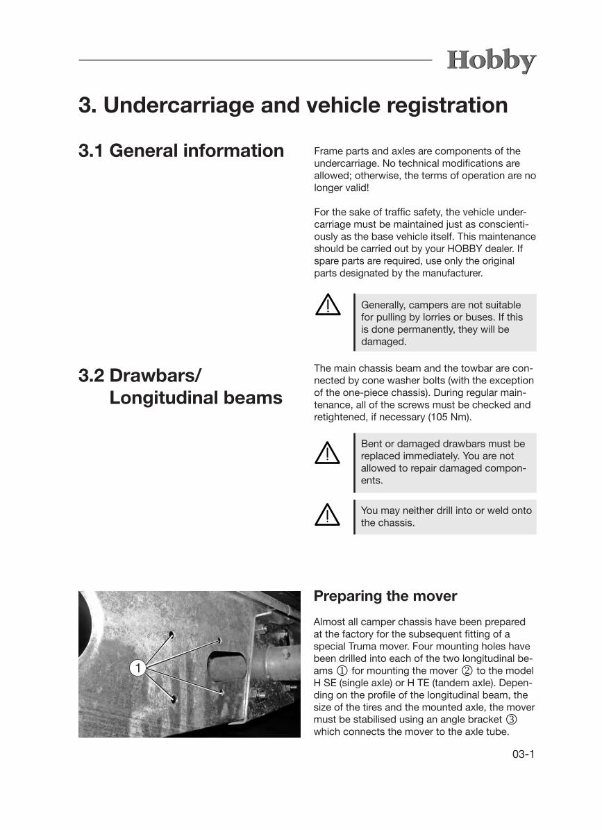
Almost all camper chassis have been prepared at the factory for the subsequent fitting of a special Truma mover. Four mounting holes have been drilled into each of the two longitudinal be-ams j for mounting the mover k to the model H SE (single axle) or H TE (tandem axle). Depen-ding on the profile of the longitudinal beam, the size of the tires and the mounted axle, the mover must be stabilised using an angle bracket l which connects the mover to the axle tube.
Bent or damaged drawbars must be replaced immediately. You are not allowed to repair damaged compon-ents.
3.2 Drawbars/ Longitudinal beams
The main chassis beam and the towbar are con-nected by cone washer bolts (with the exception of the one-piece chassis). During regular main-tenance, all of the screws must be checked and retightened, if necessary (105 Nm).
You may neither drill into or weld onto the chassis.

03-2
The Truma mover H SE / H TE has been type-ap-proved and a general operating licence has been issued for Germany. In Germany, approval is not required by a technical support organisation (TÜV, DEKRA). However, the general operating licence must be kept in the vehicle at all times.
2
3
Only the Truma mover for the models H SE and H TE may be mounted in the existing holes.
Mounting the H SE or the H TE movers without angle brackets l is not per-mitted.
It is not possible to mount the mover H SE / H TE to any of the WLU mo-dels, because the installation space is blocked by the hot air ducts.
Please see your Hobby dealer for further information or to have the complete system mounted.
3.3 Safety coupling WS 3000
The camper has been fitted with a safety coupling with tracking stabiliser to prevent it from beco-ming pendulous or pitching. This system con-forms to ISO 11555-1. It has been permitted for use up to a maximum speed of 100 km/h.Please note the additional operating instructions and the manufacturer's safety instructions.
WARNING: A safety coupling does not suspend the laws of physics. If the limits (of speed and weight con-ditions) are exceeded, traction and cornering force are reduced, which then becomes the responsibility of the driver. Therefore, avoid elevated risks.
It is not possible to mount the H SE mover on the following models; alternatively, however, the Truma SE R standard mover can be mounted:• 350 TB, 400 SFe (longitudinal beam
is too short; therefore, not enough room in front of the axle)
• 540 WLU and 560 WLU (space for mounting blocked by the styrofoam insulating case made by Düker)
• 720 KFU, 780 WLU and all models that can carry a load of 2,200 kg

03-3
4
3
1
2
3
Preparation for hitching/unhitching• To hitch and unhitch, open the tension ball coupler (lever in position j).
When dealing with higher drawbar loads hitching and unhitching is simplified by the use of a support wheel.
Hitching• The open tension ball coupler is set onto the coupling ball of the base vehicle. The tension ball coupler usually closes by applying downward pressure since the sup- port load is sufficient (lever in position k).
WARNING: Ensure that the metal of your ball coupler is bright and free of grease.
Inspection of hitch• The ball coupling is closed when the lever rests in position k or l and the green pin of the hitching display m is visible.
If the WS 3000 is not properly at- tached to the coupling ball, the camper can detach from the base vehicle.
Activation of the stabilization system • To activate the stabilization system, the operation lever must be moved downward out
of the closed position k until it locks in l. The spring corpus will become tense in the process, so that contact pressure is created on the coupling ball via the friction elements. Afterward, the operation lever lies approxi- mately parallel to the drawbar axle.
Shutoff of the stabilization system • Bring the operation lever slowly upward into
the open position (position k) to shut off the system.
Although it is possible to drive wi-thout activating the stabilizing device, e.g. when shunting, we do not re-commend that you do so.

03-4
Unhitching
5
Controlling the stabilizing device
Nach Ankuppeln und Aktivieren der Stabilisierungseinrichtung kann der Zustand der Reibelemente kontrolliert werden:
- After having hitched and activated the stabilizing device, you can then control the state of the friction pads:
- If the wear indicator n is in the green (OK) zone, the friction pads are suitable for driving.
- If the indicator is in the yellow transition zone, the friction pads must be replaced without delay.
- If the indicator is in the red (STOP) zone, there is no stabilizing function. Permission to drive at 100 km/h is immediately cancelled.
1
2
3
• Release the overrun coupling so that the gangway bellows o are expanded.
• Release the contact-breaking cable and pull out the 13-pole plug.
• Slowly pull the lever upwards into position k to switch off the stabilizing device.
• Pull the lever backwards and, at the same time, further into position j so that the
coupling opens.• After the front landing wheel has been rotated
out, the camper can be disconnected from the base vehicle.
If you do not plan on using the cam-per for a longer period of time, you should store it with the ball coupling closed.
6

03-5
3.4 Front landing wheel
Rotating it upwards and securing it • Hitch the camper to the base vehicle, aligning
the front landing wheel j to the rear end of the camper.
• Loosen the tommy screw k.• Pull the spindle tube l up as far as possible.• Tighten the tommy screw k.• Turn the crank of the front landing wheel m
clockwise to raise the wheel as far as possible and secure it to prevent it from twisting.
Before driving, always make sure that the front landing wheel has been rotated upwards as far as possible and secure it.
To lower• Loosen the tommy screw k.• Lower the spindle tube l as far as possible
until the front landing wheel is approx. 70 mm above the ground.
• Tighten the tommy screw k.• Turn the crank of the front landing wheel m
counter-clockwise to lower the wheel until it touches the ground.
• Unhitch the camper from the base vehicle and, if necessary, lower the front land wheel further.
1
2
3
4
4
3
2

03-6
3.5 Locking brake facilities
The components of the brake system, especially the overrun coupling, transmission and wheel brakes have been checked in accordance with the corresponding EU directives and may only be used in the licensed combination. If you alter or modify any components of the brake facilities, the operation permission loses its validity. Modifications may only be made with the manufacturer's permission.
Parking the carriage
When parking the carriage, the locking brake of the camper must be activated.
To lock• Pull the locking brake lever upward by the handle j until it locks into place. The locking brake lever is pressed into the final position by the gas pressure spring.
To release• Push the hand brake forward to the starting position.
1
When you park the camper after reversing it, the hand brake must be moved beyond the dead centre position to its final position in order to ensure that it is fully effective.
Rapid-emergency brake
The rapid-emergency brake is combined with the hand brake. If the camper is involuntarily discon-nected from the base vehicle, the hand brake will be tightened or moved beyond the dead centre position by the traction force of the rapid-emer-gency brake k. The hand brake will be emplo-yed and the camper will do an emergency brake. This prevents the camper from continuing to roll without braking after it has been disconnected.
Before driving, the rapid-emergency brake must be fastened to the base vehicle.
2

03-7
3.6 Overrunning equipment and wheel brakes
Checking the overrunning equipment
1. If it is possible to push the towbar more than halfway (approx. 5 mm) in when the locking brake has been activated, the braking system must be regulated immediately by an expe-rienced shop.
2. To check the reaction point, activate the locking brake and push the camper back-
wards until the hand brake lever is completely tilted. Then push the safety clutch into the overrunning equipment. The towbar must ex-tend into the neutral position by itself by me-ans of the gas cushion in the hydraulic shock absorber. Should this procedure take longer than 30 seconds, the overrunning equipment must be checked by an experienced shop.
Wheel brakes
The wheel brakes that have been used are drum brakes that do not automatically adjust. They have an automatic reverse that is sensitive to the course you drive. The linings of the wheel brakes are wear and tear parts; therefore, they must be checked every 5,000 km or at least once every year. One sure sign of strong brake lining wear is described in the aforementioned check for the overrunning equipment: if the safety clutch can be pushed in more than approx. 45 mm.
The overrunning brake facility consists of the overrun coupling, a transmission and the wheel brakes. Should the camper bump into the base vehicle, the overrunning brake facility ensures that it will automatically brake. In other words, the overrunning brake facility functions indepen-dently from the base vehicle's brake system. The brake force that is generated depends mainly on how intensely the base vehicle brakes and how heavily the camper has been loaded. A shock absorber integrated in the overrun coupling and with a defined response threshold ensures, on the one hand, a smooth overrun while, on the other hand, preventing the camper from braking if you only take your foot off the gas or change gears in the base vehicle.
03-8
The crank for the rotating stanchions is located at the front in the gas-bottle container. It is atta-ched firmly to the bottom of the container.
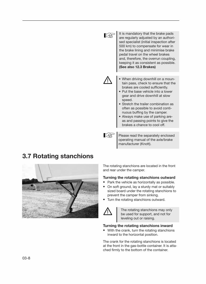
3.7 Rotating stanchionsThe rotating stanchions are located in the front and rear under the camper.
Turning the rotating stanchions outward• Park the vehicle as horizontally as possible.• On soft ground, lay a sturdy mat or suitably sized board under the rotating stanchions to prevent the camper from sinking.• Turn the rotating stanchions outward.
The rotating stanchions may only be used for support, and not for leveling out or raising.
Turning the rotating stanchions inward• With the crank, turn the rotating stanchions inward to the horizontal position.
• When driving downhill on a moun-tain pass, check to ensure that the brakes are cooled sufficiently.
• Put the base vehicle into a lower gear and drive downhill at slow speed.
• Stretch the trailer combination as often as possible to avoid conti-nuous buffing by the camper.
• Always make use of parking are-as and passing points to give the brakes a chance to cool off.
Please read the separately enclosed operating manual of the axle/brake manufacturer (Knott).
It is mandatory that the brake pads are regularly adjusted by an authori-sed specialist (initial inspection after 500 km) to compensate for wear in the brake lining and minimise brake pedal travel on the wheel brakes and, therefore, the overrun coupling, keeping it as consistent as possible. (See also 12.3 Brakes)
03-9
3.9 General inspection In accordance with Section 29 of German Road Traffic Licensing Regulations, your camper must undergo a major inspection every two years. This major inspection may be carried out by the TÜV (Technical Inspection Authority), DEKRA Vehicle Inspections or another accredited technical sup-port organisation.
The following documents must be presented at each inspection:
- motor vehicle registration certificate, Part I - valid certificate of inspection for gas facilities,
documenting installation. The initial certificate is located in the service package for the cam-per.
Vehicle ID number (FIN)The 17-digit vehicle ID number, legible from the right, is located either on the front right-hand side of the forked drawbar (models 350 - 650) or on the right-hand side of the front crossmember (models 695/780).
Furthermore, the FIN is etched on the name plate.
Please have your VIN at hand for any inquiries or whenever visiting your dealer.
3.8 Vehicle registration Every vehicle which uses public roads is subject to registration. This includes your new camper. You can register the camper at your local regis-tration office.The following documents are required to initiate the registration process:
- Motor Vehicle Registration Certificate Part II and/or Certificate of Conformity (CoC)
- insurance card- personal identification or proof of residence- possibly, power of attorney to have someone
else register the camper
If required, please do not forget to apply for a „100“ speed sticker.

03-10
3.10 Fit for a Speed of 100 km/h1. Your HOBBY camper is technically equipped
for a maximum speed of 100 km/h. Under no circumstances may this speed be exceeded!
2. Note the permissible maximum speeds for trailer carriages in the country in which you are travelling!
3. Road traffic regulations in Germany were changed on 22 October 2005. Your camper was already set to a speed of 100 at the factory, and this has been entered in the camper's registration documents. Upon request, the 100 km/h sticker will be issued by the road traffic authority when the camper is initially registered and attached to the back of the vehicle.
4. The following points must be observed, because you are responsible for adhering to them. If they are not met, the maximum speed for the camper is no more than 80 km/h!
a) The base vehicle must be equipped with an anti-locking system/anti-lock device and may not exceed an overall mass of 3.5 tons.
Name plate
Permit number
Vehicle ID number (FIN)
Permissible maximum weight
Permissible axle load, 1st axle
Permissible axle load, 2nd axle
Do not remove or change the name plate.
The name plate is located in the lo-wer front area on the right-hand side wall.

03-11
b) The camper must be equipped with hydraulic vibration dampers (shock absorbers); naturally, your new HOBBY camper is equipped with these.
c) The camper's tires may be no more than six years old. They must be marked at least with an L (= 120 km/h) for the appropriate speed category.
d) The camper must be equipped with a stabilising unit in accordance with ISO 11555-1 (standard in this HOBBY series since 1997). The overall mass of the camper may not exceed the unladen mass of the car.
5. Free interchangeability of base vehicle and camper:
Different campers may be combined with different base vehicles.
You are responsible for ensuring that the preceding regulations are met if you plan to drive at 100 km/h.
6. The correct drawbar load gives you more safety:
Please refer to page 02-5 for the recommended drawbar load.
3.11 Definition of mass Definition of masses (weights) for campersThe EG regulation 97/27/EG applies for calcula-ting the masses (weights) and for the loading which results from these calculations. The EG regulations correspnd to a great extent to the norm DIN EN 1645-2. The terms and basic calculation elements used in this description are explained in the following:
1. Gross vehicle weight rating (g.v.w.r.)The indication of the gross vehicle weight rating is taken directly from the HOBBY factory. These weights were calculated as a result of lengthy and detailed experiments; for safety reasons, they may not be exceeded.

03-12
If you are not sure whether you have overloaded the vehicle, weigh your vehicle on a public vehicle scale.
Overloading can lead to malfunction or even tire blowout!This presents the danger of the vehicle spinning out of control, which endangers you as well as other dri- vers and pedestrians.
2. Mass in running orderThe mass in running order corrsponds to the weight of the standard vehicle including all standard equipment installed at the factory (e.g. all-inclusive package) plus the basic equipment (see Item 3).
3. Basic equipmentThe basic equipment consists of all objects and fluids which are necessary for the safe and pro-per use of the vehicle. These include the masses for gas, water and electrical supply (see Item 13.3 for a detailed specification).
4. Additional loadThe additional load is the difference between the "gross vehicle weight rating minus the mass in running order". The remaining additional load must be large enough to cover the weights of possible additional equipment and personal equipment.
5. Additional equipmentAdditional equipment includes all items not part of the standard equipment preinstalled in the HOBBY factory or by the dealer. This also includes installations by special request.
The mass in running order refers to the vehicle as originally equipped by the dealer or factory. This increases accordingly if special equipment is installed.
Before the first use, we recommend that you weigh your vehicle on a calibrated vehicle scale. In this manner, you can determine the maximum permissible additional load for your vehicle.

04-1
Only use those tires designated in the registra-tion documents. Other tire sizes may only be used with the permission of the manufacturer.
• Check tires regularly to ensure that the tread is worn down evenly; check tread depth; check for external damages.• Always use the same make and model of tires (summer or winter tires). • Drive carefully on new tires for a stretch of approx. 100 km to enable them to develop a full road grip.
2 31
Due to the type of construction, the tires on campers with a tandem axle may wear out more quickly.
4. Wheels, tires
4.1 Tires
4.2 Tire pressure Only one tire size is now entered in the motor vehicle registration certificate, Parts I and II. This must not necessarily correspond with the size of the tires mounted on the vehicle. Should you have any queries, please contact your dealer.
Rules for checking tire pressure:• Check and fix tire pressure every four weeks (but at least every three months) and before every drive.• If driving on low tire pressure is unavoidable (i.e., from the campsite to the nearest service station) you should drive at a maximum speed of 20 km/h.• Tires must be checked when they are cold.
Rules for tire pressure:- correct tire pressure j- tire pressure too low k- tire pressure too high l

04-2
New tires are needed (at the latest) when the profile depth measures 1.6 mm.
Tires age even when used rarely or not at all.
Tire manufacturers' recommendation• Change tires after six years, regardless of profile depth.• Avoid striking curbs, potholes or other obstacles.
Age of tiresTires should not be more than 6 years old, be-cause on the one hand your permission to drive the camper at 100 km/h will elapse after this period and, on the other, the material wears out due to age and if the tires stand too long in one spot. The 4-digit DOT number on the side of the tire (if necessary, check the inside) shows the date of manufacture. The first 2 digits refer to the week, the last 2 to the year it was manufactured.
Example:DOT 2410 means week 24 in the year of manu-facture (here: 2010)
4.3 Profile depth and age of tires
The correct tire pressure is given in the table on wheels/tire pressure found under "Technical Information" or on the labels in the gas-bottle container and on the wheel cover.
If the tire pressure is too low, the tire can overheat. This can result in serious damage.

04-3
4.4 Rims Only use rims that are covered by the vehicle licence. Should you wish to use other rims, please note the following:
Rules for the use of other rims:- Size,- mechanisms,- compression depth and- the load/bearing capacity must be sufficient for the permissible total mass.- The chuck cone of the fastening screw must correspond to the rim mechanisms.
Modifications can only be made with the manufacturer's permission.
Rules for wheel screws:- wheel bolts must first be checked after a
distance of 50 km and then checked during regular maintenance.
Adjusting torque- for steel rims: 110 Nm- for aluminium rims: 120 Nm
WARNING: When changing rims (steel -> aluminium / aluminium -> steel) ensure that you are using the correct wheel screws.

04-4
4.5 Changing the tire
2
1
Preparing to change the tire• If possible, only change the tire when the base vehicle is coupled to the camper.• Park the trailer carriage on as firm and even a surface as possible.• If you have tire trouble on a public road, turn on your hazard warning signal lights and set up the warning triangle.• Base vehicle: Pull the handbrake, set the wheels straight, put the vehicle in gear or, if you are driving an automatic, set the gear to P.• Caravan: Pull the handbrake, leave the sup- port wheel in its driving position, deactivate the stabilization system (note: do not open completely).• Remove the wheel chocks j from the bottle compartment.
• To secure the vehicle, place the wheel chock j in front of and behind the wheel that is still intact.• Before jacking up the vehicle, turn the wheel screws once to loosen them, but do not un- screw them any further.
• The spare tire (not included, Fig. k) can be stored in the same compartment at the front of the camper as the gas container (special fasteners required). If the camper has alloy rims, note that the correct wheel screws are used when installing the spare tire affixed to a steel rim.
11

04-5
Warnings for changing the tire:
Only use the specifically designated jack for the corresponding frame parts. For example, on the axle pipe corre- sponding to the swinging lever group or on the stringer in the area of the axle fasteners. Damage or even an accident result- ing from the vehicle's toppling over can occur if the jack is applied to other parts of the vehicle.
The jack is only to be used for changing tires. It may not be used for working under the vehicle!
The rotating stanchions may not be used as a jack!
The jack is not part of the standard equipment in this series, and is there fore not included.
After changing the tire, the wheel screws must be examined (after a 50 km drive) to ensure that they are tight enough (tighten if necessary).
Changing the wheel• Set the corresponding jack onto the axle pipe of the swinging lever group or on the longitu dinal beam in the area of the axle attachments of the wheel to be changed.• On campers with a double axle, always set the jack onto the rear axle; a hydraulic jack (not included) is recommended.• If the vehicle is parked on soft ground, lay a stable reinforcement under jack (i.e., a board).• Lift the vehicle until the wheel is 2 or 3 cm off the ground.• Reposition the ratchet jack handle if it should slant when you jack up the vehicle.• Remove the wheel fastening screws and the wheel.• Attach the spare tire to the hub and adjust it.• Reattach the wheel screws and tighten them lightly over the transversal.• Lower the jack and remove it.• Tighten the wheel fatening screws evenly with the wheel wrench. The nominal value of

04-6
Tire repair kit
Do not use the tire repair kit if the tire was damaged as a result of driving without air. Small cuts, especially in the tire tread, can be resealed using the tire repair kit. Do not remove foreign objects (such as screws or nails) from the tire. The tire repair kit can be used as long as the outside temperature is approx. -30° C or higher.
A Shake the bottle. Open the fill hose j on the bottle (foil seal is thereby punctured).
B Unscrew the valve cap from the tire valve. Remove the valve insert k with the valve- core remover l. Do not lay the valve insert k down in sand or dirt.
C Pull the stopper m from the fill hose j. Push the fill hose onto the tire valve.
You should have a functional spare tire available at all times. Therefore, have the spare tire replaced without delay.
the attachment torque is 110 nm for steel rims and 120 nm for aluminium rims.• Release the handbrake and reactivate the stabilization system.

04-7
D Hold the bottle down with the filling tube and then press them together. Press the entire bottle contents into the tire. Pull the fill hose off j and screw the valve insert k tightly into the tire valve with the valve-core remover l.E Open the air hose n on the tire valve. Insert the plug o into the cigar lighter socket. Then pump the tires (Fig. p). do not operate the electric air pump longer than 8 minutes! Danger of overheating! If sufficient air pres- sure is unattainable, drive 10 meters (either forward or in reverse) so that the sealant can be evenly distributed within the tire. Repeat the pumping process. Resume driving immediately, so that the sealant can be evenly distributed within the tire. Maximum speed: 80 km/h. Drive carefully, especially in curves. Check tire pressure after driving 10 minutes. If the tire pressure has fallen under this minimum value q, you may not drive any further. If the minimum value is still indicated q, correct the tire pressure according to the tire pressure table in the gas bottle container. Drive carefully to the nearest mechanic and have the tire replaced.
Danger of accidents! If the required tire pressure is still unattainable, the tire is too severely damaged. In this case, the tire repair kit can no lon- ger provide an effective seal. There- fore, do not drive any further. Notify a service station or the 24-hour service hotline.
F Adhere the provided sticker to the combinati-on instrument within sight of the driver. Dispose of used tire repair kit at a service station. Danger of accidents! Have the tires replaced at the nearest service sta- tion.

04-8

05-1
A
B
5. Exterior structure
5.1 Ventilation and De-aerating
Rules for forced ventilationProper ventilation and de-aerating of the vehi-cle is a prerequisite for ideal living comfort. A draft-free forced-ventilation system is located in the floor and a forced de-aerating system is located in the ceiling which should not be interfered with.
Cooking, wet clothing, etc., produ-ces vapor. Every person loses up to 35 g of water per hour. Therefore, depending on the relative humidi-ty, please ventilate and de-aerate through the windows and roof bon-nets (see also "Winter operation").
We recommend that you open the roof bonnets whenever you live in the camper.
Under no circumstances may the safety ventilation be shut, not even slightly.
2
1
RefrigeratorThe ventilation bars provide the refrigerator with fresh air from outside to ensure sufficient cooling performance. The ventilation bar is located at the bottom of the exterior vehicle wall. The de-aera-tion bar is located above the ventilation bar.
There is a danger of suffocation if ventilation openings are blocked! Therefore, do not block ventilation openings.
A
B
05-2
4
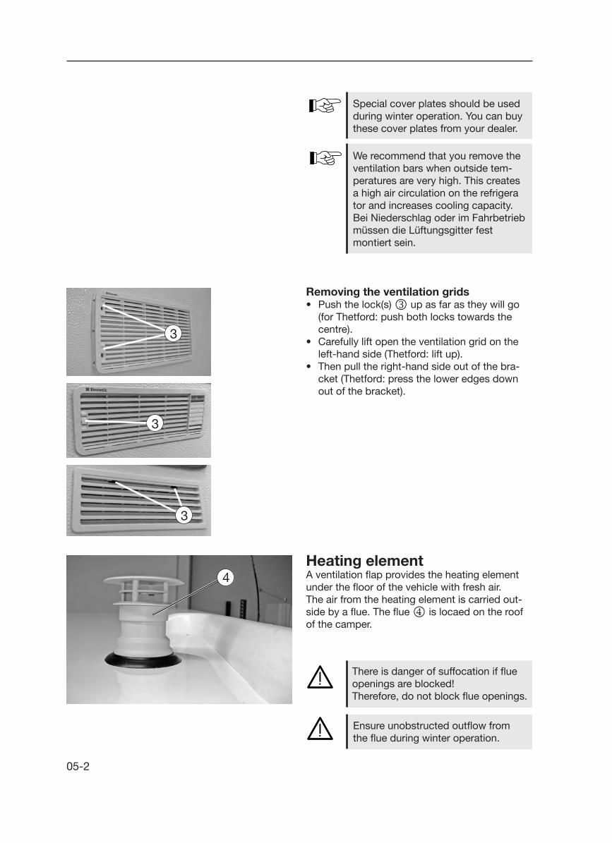
Special cover plates should be used during winter operation. You can buy these cover plates from your dealer.
We recommend that you remove the ventilation bars when outside tem- peratures are very high. This creates a high air circulation on the refrigera tor and increases cooling capacity. Bei Niederschlag oder im Fahrbetrieb müssen die Lüftungsgitter fest mon tiert sein.
Removing the ventilation grids• Push the lock(s) l up as far as they will go
(for Thetford: push both locks towards the centre).
• Carefully lift open the ventilation grid on the left-hand side (Thetford: lift up).
• Then pull the right-hand side out of the bra-cket (Thetford: press the lower edges down out of the bracket).
Heating elementA ventilation flap provides the heating element under the floor of the vehicle with fresh air.The air from the heating element is carried out-side by a flue. The flue m is locaed on the roof of the camper.
There is danger of suffocation if flue openings are blocked!Therefore, do not block flue openings.
Ensure unobstructed outflow from the flue during winter operation.
3
3
3

05-3
5.2 Entry door
External entry door
To open• Turn the key to the right until you hear the
lock open• Turn the key back to an upright position and
pull it out.• Pull on the door handle.• Open the door.
To close• Close the door.• Turn the key to the left until you hear the latch
click into place.• Turn the key back to an upright position and
pull it out.
Only drive when the entry door is shut.
The entry door is your escape route in an emergency. Therefore, never block the door from the outside!
To avoid damage, do not use the track for the insect screen as assi-stance when entering the camper.

05-4
Stable entry door
The upper l and lower k parts of the entry door can be opened and closed separately by opening the door and then unlocking the upper part l of the door from the lower part.
Unlocking the upper part of the door• Turn the lever m 90° to the left and place it in an upright position to separate the upper and lower parts of the door.• Open the upper part of the door complete- ly and press it against the outer wall of the vehicle. The door catch n will snap into its counterpart o on the outer wall of the vehi- cle and prevent the upper part of the door from shutting inadvertently.• The door frame and the lower part of the door can now be swung back separately from the upper part of the door and leaned against the outer wall of the vehicle.
2
1
3
2
4
1
5 6
4
Internal entry door
To open• Reach into the grip plate j, pull the release lever, open the door and let go of the lever.
To close• Pull the door shut.• Press the locking button k.
In this manner, a door locked from the outside can be opened from the inside.

05-5
To open• Unlatch the lock with the key.• Hold the locking knob between your thumb
and index finger and press firmly.• Open the flap downward.
To close• Close the flap upward.• Press the flap on the upper left and right-hand
corners to ensure that all of the locks actually click into place.
• Latch the lock with the key.
5.3 Service flap
Locking the upper part of the door• Turn the lever m 90° to the right and back
into an upright position to connect the upper and lower parts of the door.
• To close the whole door, use the handle to press it into the frame j.
Never close the upper part of the door if the insect screen is closed. The insect screen must always be open when you lock the door.
Entry step tread When entering and exiting the vehicle:• Place step tread in front of the entry door to the camper.• Ensure that the step tread is placed on a level surface; this prevents the step tread from falling over.
Note the varied tread heights and, when exiting, ensure you will step onto firm and even ground.

05-6
1
2
5.5 Toilet flap
1
5.4 Gas-bottle container flapTo open• Unlatch the lock j with the key.• To unlock, turn the knob that pops out in a counter-clockwise direction and open the gas-bottle container lid.
To close• Shut the lid of the gas-bottle container.• Lock the lid by turning the knob in a clockwi- se direction.• Latch the lock j with the key.• Press the knob until it snaps in and secure it.
All of the fastenings on the service flap must lock into place when closing to ensure that the flap will always be closed tight. If the flap is not closed correctly, it could become perma-nently deformed, especially when the camper stands unused for a longer period of time.
Spray the sealing gaskets of the service flaps regularly with silicon to ensure that they will always move easily and operate reliably.
To open• Unlatch the lock j with the key.• Press the knob k and swing the flap to the side.
To close• Push the toilet flap to the side until it snaps in.• Latch the lock j with the key.

05-7
The following applies for the roof load• Use only standardised and licensed ladders
that can be positioned firmly to climb onto the roof.
• The roof has not been made for concentrated loads. Place a large-scale cover over the area you wish to step on before standing on the roof. Materials with a soft and smooth surface (such as a large piece of styrofoam) are suita-ble for this purpose.
• Do not step too close to the roof bonnets or the air conditioning systems on the roof (stay at least 30 cm away).
• Do not step on the rounded areas at the front and rear ends of the camper.
The maximum total load for the roof rail is 80 kg!
Be careful when standing on the roof. There is a great danger that you will slip if the roof is wet or icy.
5.6 Roof
5.7 Guide rail for outer tent and skirtingThe keder of the outer tent slides into the guide rail for the outer tent on both sides of the cam-per, both at the front and rear ends.
The seal j under the guide rail for the outer tent has deliberately been left hanging somewhat behind the guide rail for the outer tent at the front and rear ends to ensure that rain and moisture will drip off com-pletely. The projecting seal must never be removed.
The rail channel of the outer tent rail is wider k at the rear end of the camper (above the rear lights). This makes it easier to insert the outer tent.
1
2
05-8
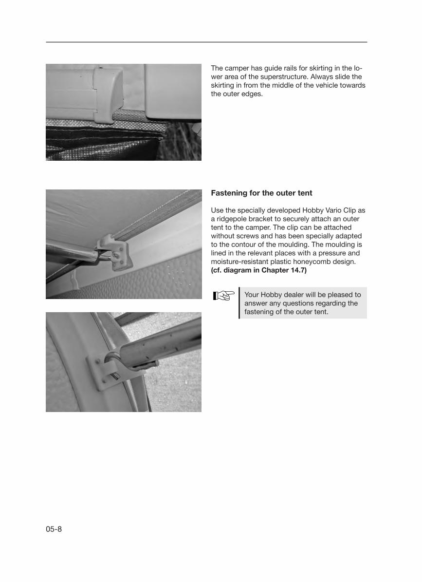
Fastening for the outer tent
Use the specially developed Hobby Vario Clip as a ridgepole bracket to securely attach an outer tent to the camper. The clip can be attached without screws and has been specially adapted to the contour of the moulding. The moulding is lined in the relevant places with a pressure and moisture-resistant plastic honeycomb design. (cf. diagram in Chapter 14.7)
Your Hobby dealer will be pleased to answer any questions regarding the fastening of the outer tent.
The camper has guide rails for skirting in the lo-wer area of the superstructure. Always slide the skirting in from the middle of the vehicle towards the outer edges.

05-9
5.8 Bicycle carrier
The maximum permissible load for the bicycle carrier is 50 kg.
The handling of the trailer carriage changes considerably when the bicycle carrier has been loaded. You should adjust your speed to take this into consideration:
• Ensure that you make full use of the permitted towbar load when the bicycle carrier has been loaded and correct it accordingly.
• Your critical speed will be dramatically redu-ced even if you have loaded the bicycle carrier optimally.
• The driver of the vehicle is responsible for ensuring that bicycles are fastened securely. The loading system must be folded up and secured with the available clips even when it is not loaded.
• Ensure that existing lighting equipment is not covered partially or completely by the load.
5.9 Roof awningAppropriate adapters and fitting components are available for subsequent assembly of roof aw-nings. Please speak to your HOBBY dealer.
The roof awning should always be assembled by an authorised specialist.
The maximum permissible total width and total height may not be exceeded by installing an awning.
Installing an awning may have a ne-gative influence on the trailer/driving performance of the camper.

05-10

06-1
Wall Cabinets in the Kitchen
To open• Press the pushbutton j on the handle to
unlock the flap.• Pull on the handle until the flap opens.
To close• Use the handle to press the flap shut until you
can feel it lock.
Furniture doors with magnetic safety catches
To open• Pull firmly on the handle until the flap or door
opens.
To close• Press on the flap or handle until you can feel
that it is held shut by the magnets.
6. Interior structure
6.1 Doors, flaps and drawers
Furniture doors with handle
Washroom door• Push the handle to open and shut the door.
Only the flaps on the kitchen wall cabinets have an extra lock. The other wall cabinets are shut using the spring force of the hinges.
1

06-2
Furniture doors with knob
Wardrobe• Turn the knob to open and shut the door.
Push-lock drawers
Kitchen drawer
To open• Press the push-lock k until the knob jumps up.• Pull on the handle l until the drawer slides out.
To close• Using the handle l, push the drawer closed.• Press the push-lock k until the knob snaps into place and the drawer is securely shut.
Drawers in the KitchenDepending on when they were manufactured, the drawers in the meter-wide kitchen are secured in different ways.
Version A:The top drawer n is secured by means of a pushlock located above the drawer k ; the drawers below it are secured by means of a central lock m.
To lock• Open the cutlery drawer n.• Press the central lock m as far down as it will
go.• Close and lock the cutlery drawer.
To unlock• Open the cutlery drawer n.• Pull the central lock m as far up as it will go.• Close the cutlery drawer n.
Version B:Each individual drawer is secured by a separate pushlock k.
4
5
2
2
3

06-3
6.2 Pivoting TV cabinet
Media oval (model-specific)
The media oval is a room divider, mounted on a pivot, which can be used as both a bar and a TV cupboard for flat screens.
To swing the media oval, pull the catch j and, after swinging out the media oval, press and snap the catch back into place to secure the media oval.
Close all flaps and drawers properly before driving. This will prevent acci-dental opening during the drive which could cause objects to fall out.
Standard KitchenThe cutlery drawer n has its own lock. The drawer can be unlocked by pressing the button o. It will lock automatically when you close the drawer.The wire basket drawers located below the cutlery drawer are secured by means of a central lock m , which is locked and unlocked in the same manner as the central lock m in the meter-wide kitchen.5
6
1
2
7
Carousel in the Corner KitchenOpen the door of the corner base cabinet by pressing the pushlock k. Pull gently on the two storage shelves p to pull them carefully out of the cabinet. Carry out this procedure in reverse order to shut the cabinet.

06-4
6.3 Extendable media shelf (model-specific)The extendable media shelf is an extendable, pivot-mounted room divider which can be used both as a bar and as a TV cabinet for flat screens.
To pull out the room divider, pull the knob n out; to secure the room divider when it has been pulled out, push the knob back in. To pivot the upper part of the media unit, pull on the pin j; after turning the unit 180°, press and lock the pin to secure the unit.
The LED lighting in the bar is switched on and off using the ambience lighting on the control panel.
The 230 V sockets and the antenna terminal l for the TV and the receiver are located under the extendable media shelf in a separately accessi-ble compartment.
While driving, the extendable media shelf must be recessed and secured.
The cables for the antenna termi-nals of both the TV cupboards and the external socket of the outer tent converge loosely in the clothes cup-board to enable you to hook up the TV sets individually.
3
5
5
1
3
4
2
1
While driving, the media oval must always be well secured and locked into place.
The switch k for turning the LED lighting for the bar on and off is located directly beneath the me-dia oval next to the 230 V sockets for the kitchen. In most models, the lighting for the bar cannot be turned on and off using the control panel.
The 230 V sockets as well as the antenna terminal l for the television and the receiver are located underneath the media oval in the top compart-ment of the kitchen L-element. The 12 V socket m shown in the photo is not included in standard delivery. (It can be ordered as an option.)

06-5
6.5 Tables
Elevating table
To lower• Turn the locking bolt j 180°.• Press on table top to lower the table.• Turn the locking bolt j back and secure the
table top.
To turn• Loosen the knurled screw k.• Turn the table in the desired (excentric) direction.• To lock the table, tighten the knurled screw k.
1 2
6.4 TV mount
As an option, all of the models that are not fitted with an extendable media shelf or media oval can be fitted with a TV mount.
To unlock• Pull the pin j up.• Swivel the support arms k to the desired position.
To lock• Fold up the TV mount until you can hear the pin j click into place.
Before you start your journey, retract the TV mount and lock it into place.
1
2

06-6
The swivelling table is not fastened to the floor. Before driving, lower the table and secure the rollers by means of the attached transportation locks.
Swivelling table
To lower• Push the handle o upwards.• Swivel the table top downwards in an arc until
the handle locks into place.
To turn• There are rollers on the table legs, shifted 45°,
which enable the table to be turned around its centre point in any desired direction.
3
4
5
Hanging table
To lower• Raise the front end of the table top by approx. 30°.• Pull down the lower part of the table leg l,
fold it over by 90° and lay it alongside.• Fold out the supporting legs m by 90°.• Pull the table top out of the upper wall brackets n.• Raise the front end of the table top by approx.
30° and hook it into the lower wall brackets.• Place the supporting legs at the front edge of
the table top on the floor.
6

06-7
Converting the Round Seating Arrangement• Remove the seat j and back cushions k.• Lower the table.• Replace the seat cushions j and pull them
to the middle of the table. • Fill the outside areas with the side back cushions k . • The rear transverse seat cushion l as well as
the rear back cushion m with the two corner cushions n are left in place.
6.6 Conversion of seats and beds
The seat groups can be converted into comfor-table beds.
Ensure that the tabletop, seat chests and/or covers as well as cushions are well secured so that nothing falls.
2 21 13
55 4
1 1
2 2
1 13
3

06-8
Bed expansion for vehicles with side seating arrangement• To open, press the push lock o.• Carefully place the external panel p on the
floor.• Place the additional panel for the bed q in a
horizontal position or tilt its longitudinal side slightly upwards.
• Raise the external panel p by approx. 60° and lower the additional panel for the bed q until the two parts support each other.
7
6
8
Bed Expansion for Long Beds
• Lift up the night table attachment r and remove it.• Pull on the handle s and pull out the slatted
frame to its full horizontal position.• Place the additional cushion on the slatted
frame.
It is possible to obtain an optional bed expan-sion with which to widen the two long beds, turning them into a double bed.
1211
9
10
11
12

06-9
6.8 WindowsHinged windows
To openThe window can be adjusted to open at varying degrees:• Turn the latch into the vertical position.• Press the window outward until you hear a click. The window automatically remains in this position.
To close• Lift the window slightly outward so that the hinge disengages.• Shut the window.• Turn the latches into the vertical position.
Windows by the children's beds are secured against accidental opening, to effectively prevent children from falling out.
6.7 Children's beds
The permissible maximum load for the upper bunk bed is 75 kg.
• Windows by the children's beds are secured against accidental opening, to effectively pre vent children from falling out.
Be careful when using the upper bed for small children, as there is a danger that they may fall out. Never leave small children unattended in the caravan.
06-10
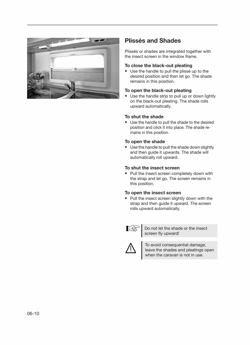
Plissés and Shades
Plissés or shades are integrated together with the insect screen in the window frame.
To close the black-out pleating• Use the handle to pull the plissé up to the desired position and then let go. The shade remains in this position.
To open the black-out pleating• Use the handle strip to pull up or down lightly on the black-out pleating. The shade rolls upward automatically.
To shut the shade• Use the handle to pull the shade to the desired position and click it into place. The shade re- mains in this position.
To open the shade• Use the handle to pull the shade down slightly and then guide it upwards. The shade will automatically roll upward.
To shut the insect screen• Pull the insect screen completely down with the strap and let go. The screen remains in this position.
To open the insect screen• Pull the insect screen slightly down with the strap and then guide it upward. The screen rolls upward automatically.
Do not let the shade or the insect screen fly upward!
To avoid consequential damage, leave the shades and pleatings open when the caravan is not in use.

06-11
Roof fanThe roof fan can be set up either on one or both sides.
To open• Press the spring lock towards the inside of
the roof fan while, at the same time, using the handle to press the roof fan upwards.
To close• Use both handles to pull the roof fan firmly
downwards until both spring locks have lat-ched into place.
Shade/insect screenWhen the insect screen is shut and locked to-gether with the shade, it is still possible to pull down the shade. When you pull down the shade, the insect screen will automatically be pulled with it.
To close• Press the lock towards the outside of the roof
fan.• Pull the handle of the screen towards the
handle of the opposite screen and let it latch into place.
To open• Press the handle together; this releases the
lock.• Take hold of the handle and slowly guide the
screen back.

06-12
Large roof bonnet
To open the roof bonnetBefore opening the bonnet, ensure that the area above the opening of the bonnet is free. The bonnet can be opened to an angle of 60°.
• Reach into the opening of the crank bag and fold the crank to the user position by pulling it out. Turn the crank clockwise to open the bonnet to the desired position. When you have reached the maximum opening angle you will feel the resistance.
To close the roof bonnet• Turn the crank counter-clockwise until the
bonnet is closed and you feel the resistance. When the bonnet is closed, you can fold the crank back into the crank bag. To be locked securely, the crank must be folded into the crank bag.
6.9 Roof bonnets Safety instructions
• Never open the roof bonnets in a strong wind or when it is raining, hailing, etc., or if the outside tem-perature is below -20° C!
• Never use force to open the roof bonnets if they are frozen or cove-red with snow, because you may break the hinges and the opening mechanism.
• Before opening, remove snow, ice or heavy dirt. Make a note of the required space needed before opening the roof bonnet under a tree, in a garage, etc.
• Do not step on the roof bonnet.• Close and lock roof bonnets be-
fore driving. Open insect screen and shade (home position).
• Close shade only 3/4 of the way if the sun shines in strongly; danger of heat accumulation!
The openings for the forced ventilati-on system must always be left open! Never close or cover forced ventilati-on systems!

06-13
Small roof bonnet
To open the roof bonnet• This roof bonnet can be opened to three
different settings in the opposite direction to traffic. Press the locking knob on the side and use the adjusting lever to move the roof bon-net to the desired position; then click it into place. The bonnet has a maximum opening angle of 50°.
To close the roof bonnet• Release the adjusting lever from its catch
position and close the roof bonnet. The bon-net is automatically locked when it has been completely closed.

06-14

07-1
7. Installation of electrical devices
7.1 Safety tips The installation of electrical devices in the HOB-BY camper has been carried out in accordance with the valid regulations and standards.
Please note
Do not remove safety tips and war-nings on the electrical equipment.
The installation spaces for electrical equipment such as distribution fuse boards, electric power supply, etc., may not be used as additional sto-rage spaces.
The standard version of the camper is not equipped for internal battery supply (self-sufficient operation).
Only authorised specialists may work on the electrical system.
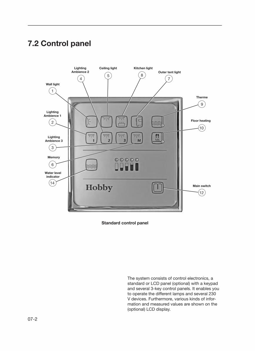
07-2
7.2 Control panel
The system consists of control electronics, a standard or LCD panel (optional) with a keypad and several 3-key control panels. It enables you to operate the different lamps and several 230 V devices. Furthermore, various kinds of infor-mation and measured values are shown on the (optional) LCD display.
Standard control panel
12
10
785
4
1
2
3
6
14Main switch
Floor heating
Therme
Outer tent lightKitchen lightCeiling lightLighting
Ambience 2
Wall light
LightingAmbience 1
LightingAmbience 3
Memory
Water level indicator
9

07-3
LCD control panel (special request)
12
11
10
785
4
1
2
3
6
14
Main switch
Navigation keysfor the menu
Floor heating
Therme
Outer tent lightKitchen lightCeiling lightLighting
Ambience 2
Wall light
LightingAmbience 1
LightingAmbience 3
Memory
LCD Display
9
Functions of the main switch• After initially connecting the camper to the
230 V mains, you must press either the main switch or any other control key in order to activate all of the 12 V electrical devices and the 230 V electrical devices that are switched by the system (e.g. therme, floor heating).
• Once the system is in operation, press the main switch briefly to turn all of the lights off. All of the 12 V steady electrical devices (e.g. water supply, refrigerator control, heat blower)

07-4
Wall Lamps and Ceiling Lamp • Briefly press the key to switch each lamp on
and off. Press longer on the key to regulate how brightly you want the lights to shine. The brightness you set will be saved; when the lights are switched on again, the brightness you originally set will also be switched on again. If the system's power supply is inter-rupted, the wall light will shine full strength the first time you switch it on.
1 5
Ambience• Press briefly on the key to switch the electric
circuit of each ambience (indirect lighting) on and off.
42 3
If the ignition of the base vehicle has been switched on, the refrigerator will operate automatically on 12 V, i.e. it is not necessary to press the main switch. All other 12 V electrical devices will only operate on the bat-tery of the base vehicle if the main switch has been activated.
remain activated. The devices that were pre-viously switched on are stored in the system; pressing on the main switch reactivates them. This also resets the degree to which those lights were dimmed that can be regulated.
• Pressing the main switch for at least four seconds while the system is switched on will turn off not only the presently activated devices, but also the entire 12 V system (in self-sufficient campers, this will not cut off the charging of the battery).
• If there should be a power failure, the system will remember whether the main switch was on or off. As soon as the power is back on, the main switch will automatically switch itself back on. Electrical devices that continuous-ly use current, such as the heating, will then begin to operate again.
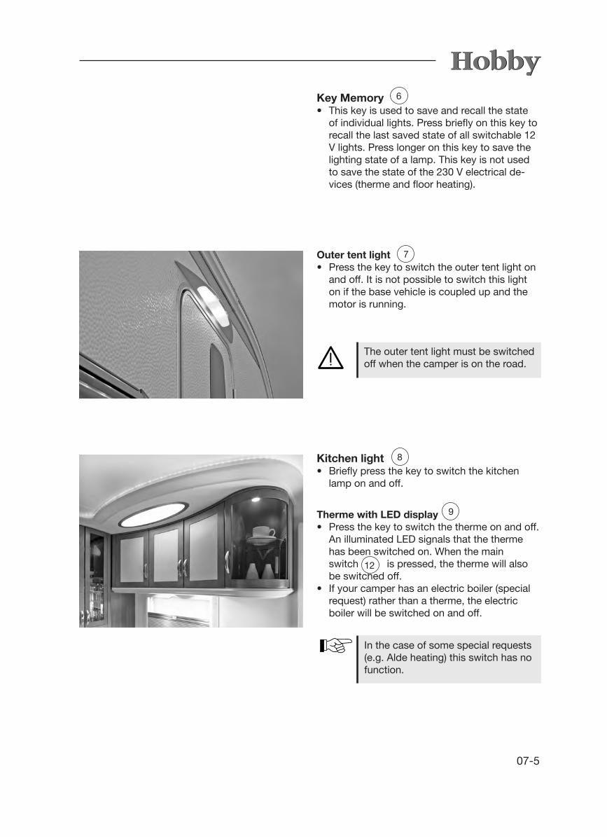
07-5
The outer tent light must be switched off when the camper is on the road.
In the case of some special requests (e.g. Alde heating) this switch has no function.
Outer tent light • Press the key to switch the outer tent light on
and off. It is not possible to switch this light on if the base vehicle is coupled up and the motor is running.
7
Key Memory • This key is used to save and recall the state
of individual lights. Press briefly on this key to recall the last saved state of all switchable 12 V lights. Press longer on this key to save the lighting state of a lamp. This key is not used to save the state of the 230 V electrical de-vices (therme and floor heating).
6
Kitchen light• Briefly press the key to switch the kitchen
lamp on and off.
8
Therme with LED display • Press the key to switch the therme on and off.
An illuminated LED signals that the therme has been switched on. When the main
switch is pressed, the therme will also be switched off.
• If your camper has an electric boiler (special request) rather than a therme, the electric boiler will be switched on and off.
12
9

07-6
Both the therme and the floor heating (special request) are 230 V electri-cal devices. These devices cannot be switched on and off if there is no mains connection.
Filling level indicator When you press this key, the filling level of the fresh water tank is displayed via an LED chain. The level of the fresh and waste water tanks is displayed in 5 steps:
empty only the left red LED lights up¼ left red LED off; 1 yellow LED on½ left red LED off; 2 yellow LEDs on¾ left red LED off; 2 yellow and 1 green LED onfull left red LED off; 2 yellow and 2 green LEDs on
Align the vehicle horizontally to obtain a meaningful result from the filling level indicator.
14
Floor heating with LED display • Press the key to switch the therme on and off.
An illuminated LED signals that the therme has been switched on. When the main switch is pressed, the therme will also be switched off.
• If your camper has an electric boiler (special request) rather than a therme, the electric boiler will be switched on and off.
10
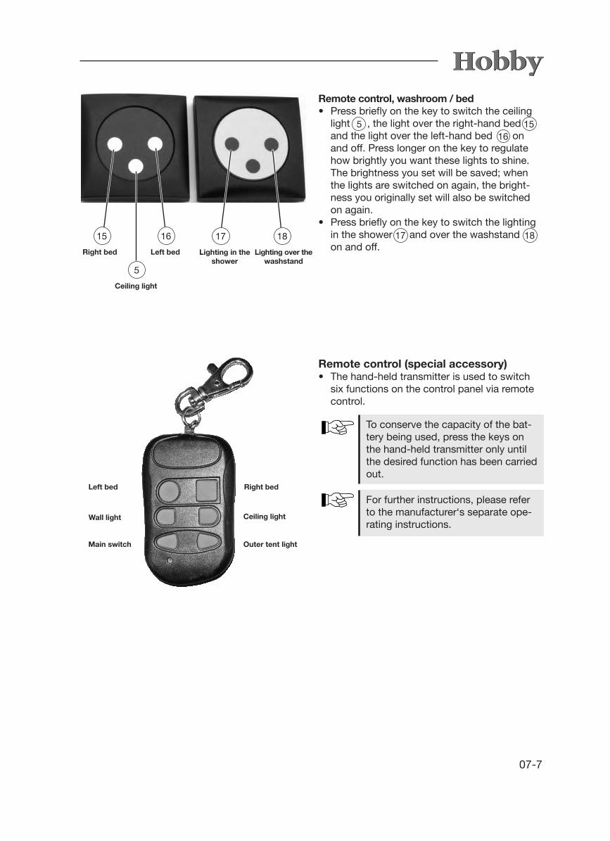
07-7
To conserve the capacity of the bat-tery being used, press the keys on the hand-held transmitter only until the desired function has been carried out.
For further instructions, please refer to the manufacturer‘s separate ope-rating instructions.
Remote control (special accessory)• The hand-held transmitter is used to switch
six functions on the control panel via remote control.
Remote control, washroom / bed• Press briefly on the key to switch the ceiling
light , the light over the right-hand bed and the light over the left-hand bed on
and off. Press longer on the key to regulate how brightly you want these lights to shine. The brightness you set will be saved; when the lights are switched on again, the bright-ness you originally set will also be switched on again.
• Press briefly on the key to switch the lighting in the shower and over the washstand on and off.
5 1516
181715
Right bed
16
Left bed
5
Ceiling light
17
Lighting in the shower
18
Lighting over the washstand
Left bed Right bed
Wall light Ceiling light
Main switch Outer tent light

07-8
Basic menu • The basic menu appears if you have not
pressed a navigation key during the past 30 seconds (approximately). This menu is not illuminated.
Time • The current time is displayed in this field.
Date • The current date is displayed in this field.
Connection to base vehicle• This icon appears if the camper is connected
to the base vehicle and the motor of the base vehicle has been started. This function is only displayed when the vehicle has been equipped with a "self-sufficient package".
Mains connection • This icon appears if the camper is connected
to the 230 V mains.
Main switch• The icon for the main switch always appears
when the system's 12 V main switch has been switched on.
LCD display
Charging/discharging • This icon only appears when the system is con-
nected to a battery sensor and equipped with its own battery. The icon depicts the dischar-ging of the camper's battery. While the battery is being charged, the arrow points towards the battery. This function is only displayed when the vehicle has been equipped with a "self-suffici-ent package".
Alarm clock • This icon is use to activate the alarm clock. The example shows the alarm clock when it has
been deactivated. When it is activated, there is no line through the icon.
Current time Current date
Connection to base vehicle
Mains connectionMain switch
Charging/discharging
Alarm clock
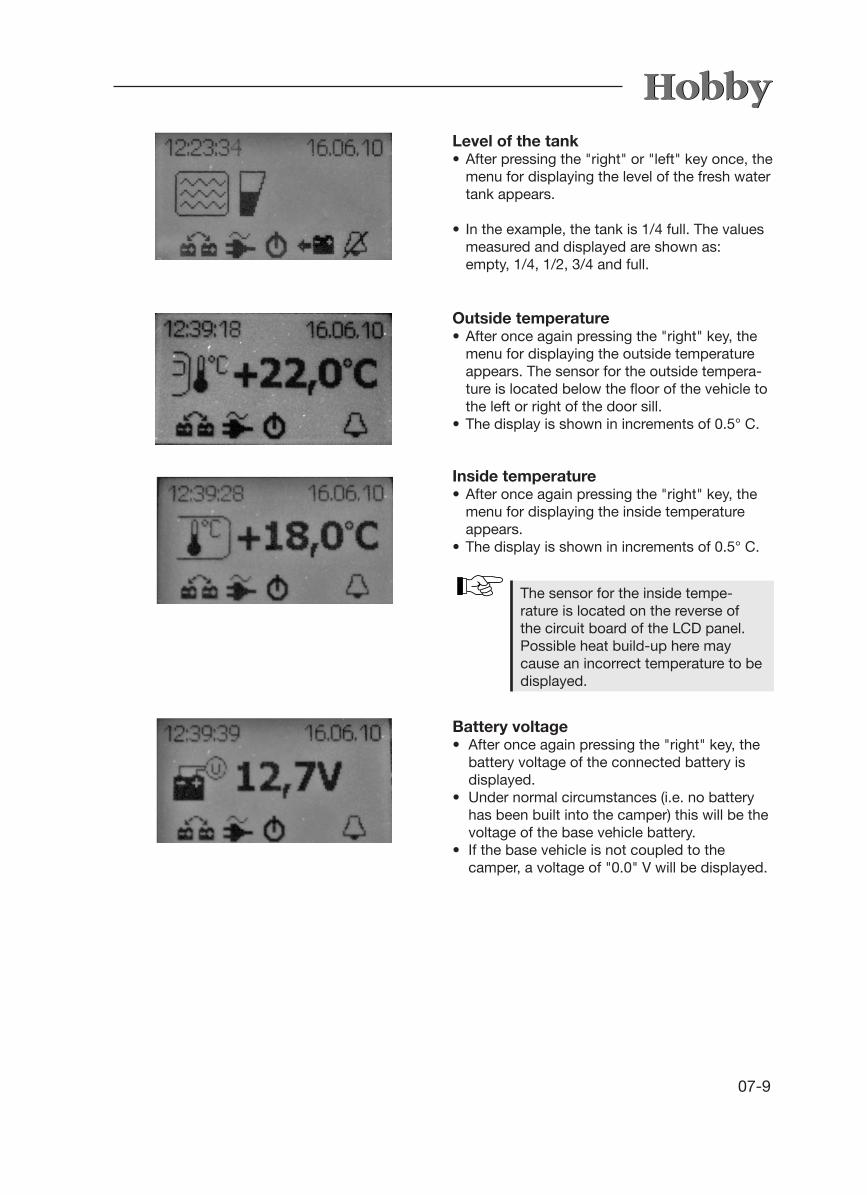
07-9
Level of the tank• After pressing the "right" or "left" key once, the
menu for displaying the level of the fresh water tank appears.
• In the example, the tank is 1/4 full. The values measured and displayed are shown as:
empty, 1/4, 1/2, 3/4 and full.
Outside temperature • After once again pressing the "right" key, the
menu for displaying the outside temperature appears. The sensor for the outside tempera-ture is located below the floor of the vehicle to the left or right of the door sill.
• The display is shown in increments of 0.5° C.
Battery voltage • After once again pressing the "right" key, the
battery voltage of the connected battery is displayed.
• Under normal circumstances (i.e. no battery has been built into the camper) this will be the voltage of the base vehicle battery.
• If the base vehicle is not coupled to the camper, a voltage of "0.0" V will be displayed.
The sensor for the inside tempe-rature is located on the reverse of the circuit board of the LCD panel. Possible heat build-up here may cause an incorrect temperature to be displayed.
Inside temperature• After once again pressing the "right" key, the
menu for displaying the inside temperature appears.
• The display is shown in increments of 0.5° C.

07-10
Setting the time, alarm clock and date• After pressing the "up" and "down" keys
simultaneously for a longer period of time (ap-prox. 2 seconds) the menu for setting the cur-rent time, date, wake-up time and activating or deactivating the alarm clock appears.
• Use the "right" and "left" keys to proceed to the individual settings in this menu. The selected value is underlined by a blinking line. The "up" and "down" keys are used to change the values. Exit the menu by pressing the "up" or "down" key when "Exit" is underlined.
General information regarding the LCDdisplayThe time and date are buffered by a 3V 210 mAh, CR2032 type button cell. If, therefore, the time should be incorrect or the clock should stop working, this button cell must be replaced. It is mounted on the reverse of the circuit board of the LCD display. To replace this button cell, the LCD display must be removed from the furniture front by carefully clipping the chrome-plated fra-me out of its holder. You will then see the screws that fasten the plastic part to the furniture. Loosen these screws to detach the display.
When replacing the button cell, please ensure that plus and minus are in the right direction. Incorrect polarity may cause the display to become defect.

07-11
7.3 Electrical supply
Supply via mains connectionThe camper receives its electric power supply via the 230 V CEE feeder plug on the side wall of the vehicle.
To set up an electric connection• Pull out the 13-pole plug that connects to the
base vehicle.• Switch off the automatic circuit breaker m by
pressing the rocker button down n.• Take hold of the bottom of the cover flap of
the external socket j and pull it up.• Completely unwind the connector cable, at-
tach the plug k and click it into place.• Switch the automatic circuit breaker m back on.
To disconnect the electric connection• Switch off the automatic circuit breaker m by
pressing the rocker button down n.• Press the lever l in the external socket
down.• Remove the CEE plug k.• Press the cover flap j down until it clicks
into place.
The 230 V system is protected by a two-pole 13 A automatic circuit breaker m, which is loca-ted in the clothes cupboard. (Exceptions to this include special installations, such as ultraheat, hot-water heating, etc.. In this case, an addi-tional two-pole 16 A circuit breaker has been installed.) If there are two automatic circuit brea-kers, both must be switched on.
Electricity for the camper can be obtained from the following connections:- 230 V mains connection 50 Hz- via the base vehicle if it is connected using
the 13-pole plug (limited functions)- via a built-in auxiliary battery (special request)
Everything that uses 12 V, such as lighting, water supply, etc., is available.
2
1
3
4
5
The external 230 V supply must be protected by a residual current device (RCD).
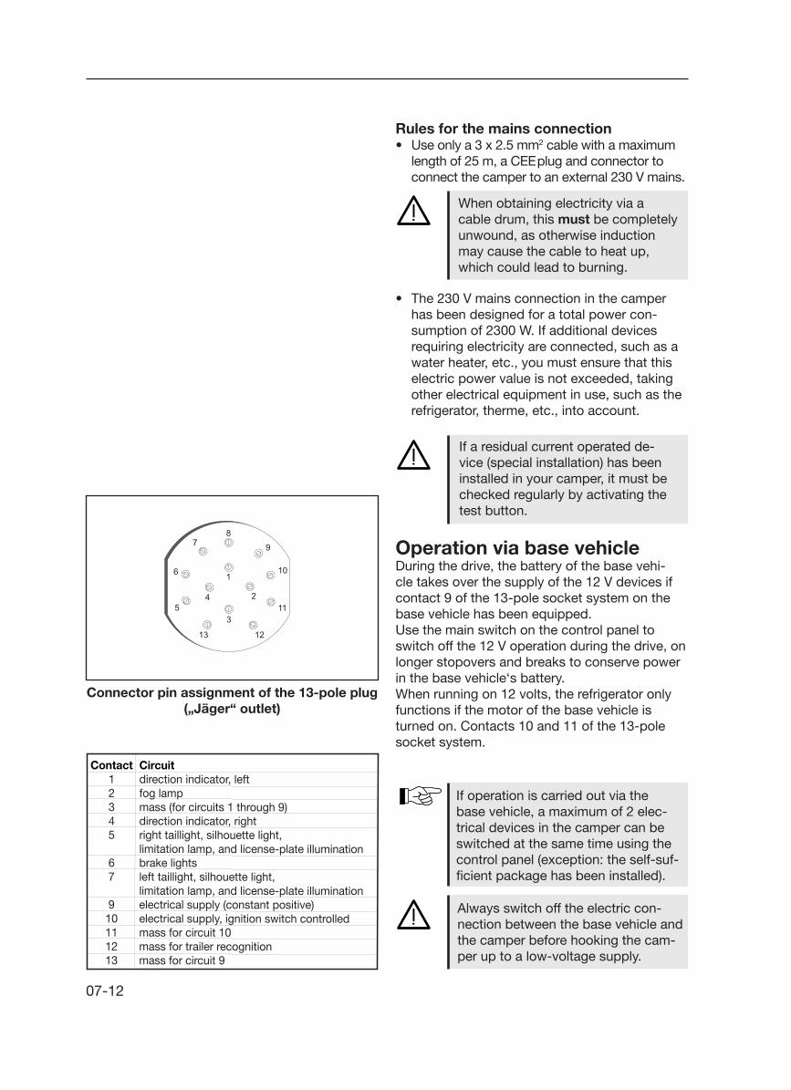
07-12
Rules for the mains connection• Use only a 3 x 2.5 mm2 cable with a maximum
length of 25 m, a CEE plug and connector to connect the camper to an external 230 V mains.
• The 230 V mains connection in the camper has been designed for a total power con-sumption of 2300 W. If additional devices requiring electricity are connected, such as a water heater, etc., you must ensure that this electric power value is not exceeded, taking other electrical equipment in use, such as the refrigerator, therme, etc., into account.
When obtaining electricity via a cable drum, this must be completely unwound, as otherwise induction may cause the cable to heat up, which could lead to burning.
If a residual current operated de-vice (special installation) has been installed in your camper, it must be checked regularly by activating the test button.
Operation via base vehicleDuring the drive, the battery of the base vehi-cle takes over the supply of the 12 V devices if contact 9 of the 13-pole socket system on the base vehicle has been equipped.Use the main switch on the control panel to switch off the 12 V operation during the drive, on longer stopovers and breaks to conserve power in the base vehicle‘s battery.When running on 12 volts, the refrigerator only functions if the motor of the base vehicle is turned on. Contacts 10 and 11 of the 13-pole socket system.
If operation is carried out via the base vehicle, a maximum of 2 elec-trical devices in the camper can be switched at the same time using the control panel (exception: the self-suf-ficient package has been installed).
Always switch off the electric con-nection between the base vehicle and the camper before hooking the cam-per up to a low-voltage supply.
Connector pin assignment of the 13-pole plug („Jäger“ outlet)
Contact Circuit 1 direction indicator, left 2 fog lamp 3 mass (for circuits 1 through 9) 4 direction indicator, right 5 right taillight, silhouette light, limitation lamp, and license-plate illumination 6 brake lights 7 left taillight, silhouette light, limitation lamp, and license-plate illumination 9 electrical supply (constant positive) 10 electrical supply, ignition switch controlled 11 mass for circuit 10 12 mass for trailer recognition 13 mass for circuit 9

07-13
Operation via auxiliary battery(self-sufficient package)
• Only accumulator batteries with bound electrolytes (gel batteries) may be installed in those positions specified by the manufacturer.
• The installed gel battery may not be opened.
• When changing auxiliary batteries, use only batteries of the same make and capacity.
• Before disconnecting or connecting the auxiliary battery, disconnect the electric connection to the base vehi-cle and switch off the 230 V supply, the 12 V supply as well as all electri-cal devices.
• Before replacing fuses you must first de-energise the charge controller.
• Before replacing a blown fuse you must first fix whatever caused the fuse to blow.
• Fuses may only be replaced by fuses with the same fuse protection value.
• Airing the charge controller insuffi-ciently will cause a reduction of the charge current.
• The surface of the charge controller casing may become hot when the device is in operation.
Operating and loading the auxiliary batteryIf the camper is not connected to the 230 V mains supply, the auxiliary battery will supply the electri-cal system with 12 V DC voltage. Since the batte-ry only has a limited capacity, the electrical de-vices should not be operated for a longer period of time without charging the battery or connecting the camper to the 230 V mains connection. The charge controller is used to charge the battery. There are three possible sources of input: 230 V mains connection, generator of the base vehicle or possibly a solar panel, whereby the source of input with the highest input voltage supplies the charge current for the connected battery.

07-14
7.4 Electrical systemAs soon as there is a mains connection, the electrical system will switch from battery operati-on to mains operation.
The electrical supply unit uses a converter to transform the external mains voltage for the 12 Volt electrical devices.
All of the lamps in the camper use 12V. Only large electrical devices such as the therme, floor heating, air conditioner, etc., use 230V.
• Always charge the auxiliary battery for at least 20 hours before each journey, directly after each journey and before you take the camper temporarily out of service.
• Use every opportunity during your journey to charge the battery.
• The battery loses its capacity after having been used for a while and at low temperatures.
• An acoustic warning signal will be given off if the remaining time during discharge operation is less than
1 hour.• If the battery voltage should be less
than 10.0 V, all devices will automa-tically be switched off.
• A warning will go off if the battery ages to a value less than 50% of its nominal capacity.
• The battery is only charged if it has a minimum voltage of 8 V.
• If the vehicle is not in use for a longer period of time, the battery should be disconnected after it has been optimally charged.
• For further information, please refer to the separate operating in-structions for the charge controller.

07-15
Assignment of fusesThe fuses for the individual internal electric cir-cuits are located in the lighting control module. They are assigned as follows (from left to right):
Electric circuit 1 (15 A):children‘s bedside lights, clothes cupboard light (only WLU), outer tent light, wall lights, ceiling light, bedside lights
Electric circuit 2 (15 A):children‘s bedside lights
Electric circuit 3 (15 A):clothes cupboard light, left bedside light (only WLU), ambience 2, kitchen, shower
Electric circuit 4 (15 A):fan, washstand, ambience 3, ambience 1
Electric circuit 6 (7.5 A):water supply, Porta Potti, refrigerator illumination
Only replace defect fuses if you know what caused the fuse to blow and have fixed this.
Only replace defect fuses if you know what caused the fuse to blow and have fixed this.Your camper also has a combined external socket and antenna terminal in the outer tent (deluxe special accessory).
This can be used, for example, to set up a TV in the outer tent. Depending on how you wire it, the integrated antenna terminal can be used as either an input or an output socket. For further information, please speak to your Hobby dealer (also see 6.2).
In some models, there may be slight deviations in this assignment.

07-16
7.5 External circuit diagram
rehcuarbreVttinhcsreu
QebrafredA
NIP²
mm ni
sknil ,regieznasgnuthcirtrhaF5,1
bleg1
ethcuelßulhcslebeN5,1
ualb2
)8 sib 1 sierkmortS rüf( essa
M5,2
ßiew3
sthcer ,regieznasgnuthcirtrhaF5,1
nürg4
gnuthcuelebnehcieznneK dnu ethcuelsgnuznergeB,ethcuelßirmU ,ethcuelßulhcS ethceR
5,1nuarb
5
nethcuelsmerB
5,1tor
6
gnuthcuelebnehcieznneK dnu ethcuelsgnuznergeB,ethcuelßirmU ,ethcuelßulhcS ekniL
5,1zrawhcs
7
refrewniehcsrhafkcüR5, 1
egnaro8
)sulpreuaD( gnugrosrevmortS
5,2ualb
9
treuetseg retlahcsdnüZ ,gnugrosrevmortS
5,2ßiew / ualb
01
01 rüf essaM
5,2tor / ßiew
11
3 nov essaM gnunnekreregnähnA
5,1tteloiv
21
9 rüf essaM
5,2ualb / ßiew
31
Sid
e p
ositi
onin
g lig
ht 5
W
Red
cle
aran
ce li
ght
5W
Fron
t ru
nnin
g lig
ht w
ith
refle
ctor
5W
12 V
Ele
ctric
al In
stal
latio
n fo
r Ve
hicl
e
LED
bra
ke li
ghts
Red
cle
aran
ce li
ght
5W
Rou
te-i
ndic
atin
g si
gnal
21W
bra
ke li
ghts
21W
Taill
ight
10W
Rea
r fo
g lig
ht 2
1W
Num
ber
pla
te li
ght
5W
PIN
PIN
Wir
e co
lour
mm
2C
ons
umer
1ye
llow
1,5
Rou
te-i
ndic
atin
g si
gnal
, lef
t
2b
lue
1,5
Rea
r fo
g lig
ht
3w
hite
2,5
Mas
s (fo
r el
ectr
ic c
ircui
t 1-
8)
4gr
een
1,5
Rou
te-i
ndic
atin
g si
gnal
, rig
ht
5b
row
n1,
5R
ight
tai
lligh
t, c
lear
ance
ligh
t, r
unni
ng li
ght
and
num
ber
pla
te li
ght
6re
d1,
5B
rake
ligh
ts
7b
lack
1,5
Left
tai
lligh
t, c
lear
ance
ligh
t, r
unni
ng li
ght
and
num
ber
pla
te li
ght
8or
ange
1,5
Rev
erse
ligh
t
9b
lue
2,5
Ele
ctric
pow
er s
upp
ly (s
tead
y p
lus)
10b
lue
/ w
hite
2,5
Ele
ctric
pow
er s
upp
ly, i
gniti
on-c
ontr
olle
d
11w
hite
/ r
ed2,
5M
ass
for
10
12vi
olet
1,5
Trai
ler
num
ber
pla
te, m
ass
from
3
13w
hite
/blu
e2,
5M
ass
for
9
Dis
trib
utio
n b
ox 1
2V
Sid
e p
ositi
onin
g lig
ht, l
eft
Sid
e p
ositi
onin
g lig
ht, r
ight
Pos
ition
ing
and
cl
eara
nce
light
, lef
t
Pos
ition
ing
and
cle
a-ra
nce
light
, rig
ht
bla
ck
whi
te
bro
wn
whi
te/b
lue
blu
e/w
hite
blu
e
whi
te/r
ed

07-17
Die Kontaktbelegungen können bei einigen Modellen leicht abweichen.Die genaue Kontaktbelegung �nden Sie im Leitungsplan des Fahrzeuges.
S37
7,5A
34
35
361 2 3 4
S41+ + - -
+ -383940
1
+ -+ -
2
3
18
3031
32
33
8
13
4
9
14
5
10
15
23
6
11
16
12
7
17
21
Ambiente3c
19
Ambiente2b
Ambiente2a
20Ambiente
3a
24
Ambiente1a28
Ambiente3b25
26
27
Ambiente1c29
Ambiente1b22
230V current range
Therme
Floor heating
Input lead
Protective conductor
S40 10/11 from plusterminal ignition circuit
S39 to charge controller,control RE+-(only self-sufficient / 12V)
Plus electrical supply
S38 to charge controller,input 1 charging current(only self-sufficient / 12V)
9 and 13 from car orconnection to charge controller,
battery connection for self-sufficient / 12V
Fuses 15A
Bridge circuit from S37 to 4
S37
eart
h co
nnec
tion
to P
E4
Wall light dimmerr
Ceiling light
dimmerChildren's bedside lights III
Children's bedside lights
Clothes cupboard
light
Fan Water supply
For WLU: left bed
Porta Potti
For WLU: clothes
cupboard light II
Clothes cupboard roof cable
Clothes cupboard roof cable
Clothes cupboard roof cable
Outer tent light Washstand
Shower
Jumper 1closed for
self-sufficient / 12 Fz
Dimmer for left-hand
bed
Dimmer for right-hand
bed
Connection for external keysBattery monitoring control
Mai
n pa
nel
Bath
room
Bed
Bed
Radi
oKi
tche
n
Contact assignments may differ slight-ly in some models. Please refer to the electric wiring diagram for this vehicle for the exact assignment of all contacts.
7.6 Contact plan for the light control system

07-18
Children‘s bed light is switched on and off by turning the bear‘s nose.This light can be dimmed and set as a night light („blue ears“ - cannot be switched on the control panel). The night light is switched on and off separately by means of a switch underneath the children‘s bed light.
3
The clothes cupboard light l is switched on and off by opening the doors of the cupboard (integrated contact switch - cannot be switched on the control panel). The LED light is battery-operated. Before initial operation, pull off the foil that prevents battery contact.
1
2
Corner lights
Spotlight j and integrated lighting columns k can be switched separately.
7.7 Special LightsThe switches for the lights described here are located directly on the lights themselves; they are not controlled via the control panel.
08-1
8. Water8.1 General information
Function of the water supplyWater is provided to the kitchen and toilet area via an immersion pump. The immersion pump functions on electricity:- via a 12 volt automobile battery if the camper
is connected via a plug to the base vehicle,- via a transformer if the camper is connected
to the 230 volt main.- In self-sufficient mode (special accessory) via
the installed auxiliary battery.
Rules for the immersion pump• The immersion pump is only suitable for water.• The immersion pump tolerates temperatures
up to 60° C for a short time.• Avoid dry runs.
The water supply system corresponds at least to the state of the art as of 03/2009 (Directive 2002/72/EC). Despite this, we recommend that you inspect any water you have filled in very critically before using it.
Please note• Water that is suitable for drinking should
always be used with working with food. This also applies to washing your hands and clea-ning the objects that have come into contact with food.
• To ensure that the quality of the water is fault-less, the water should be taken directly from the public drinking water system.
• Under no circumstances should garden ho-ses, watering cans and similar materials that are unsuitable for drinking water be used to fill the mobile system.
• If the caravan will not be used for a longer period of time, the entire water system must be emptied completely.
• After long periods of stagnation, the water system must be rinsed thoroughly before it is used again. If you find that it is contaminated, the material should be disinfected using clea-ning agents that are permitted and suitable.
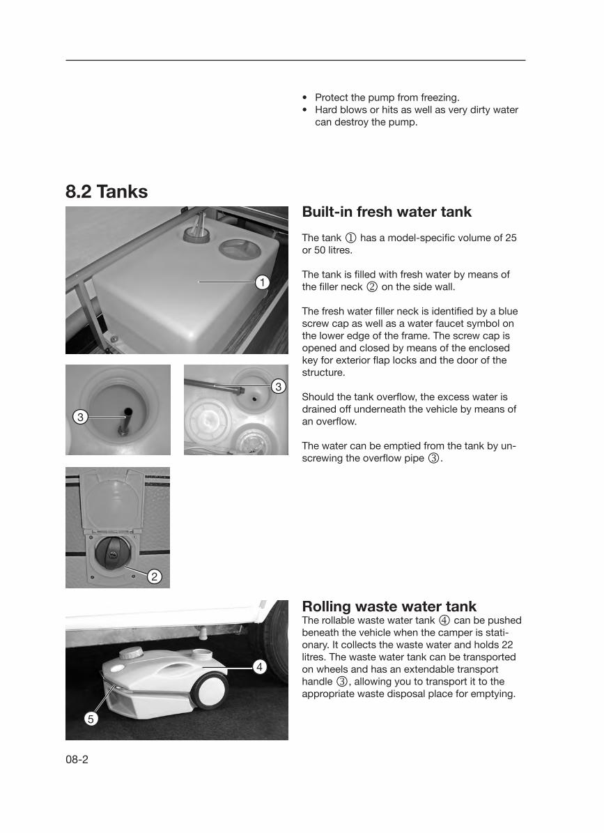
08-2
8.2 Tanks
Rolling waste water tankThe rollable waste water tank m can be pushed beneath the vehicle when the camper is stati-onary. It collects the waste water and holds 22 litres. The waste water tank can be transported on wheels and has an extendable transport handle l, allowing you to transport it to the appropriate waste disposal place for emptying.
4
5
Built-in fresh water tank
The tank j has a model-specific volume of 25 or 50 litres.
The tank is filled with fresh water by means of the filler neck k on the side wall.
The fresh water filler neck is identified by a blue screw cap as well as a water faucet symbol on the lower edge of the frame. The screw cap is opened and closed by means of the enclosed key for exterior flap locks and the door of the structure.
Should the tank overflow, the excess water is drained off underneath the vehicle by means of an overflow.
The water can be emptied from the tank by un-screwing the overflow pipe l.
1
3
3
• Protect the pump from freezing.• Hard blows or hits as well as very dirty water
can destroy the pump.
2
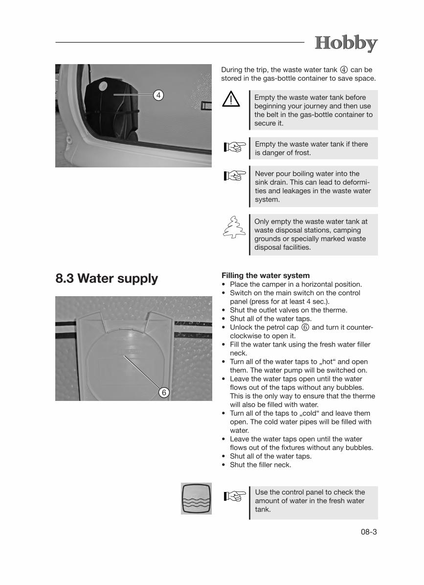
08-3
8.3 Water supply
Empty the waste water tank before beginning your journey and then use the belt in the gas-bottle container to secure it.
Empty the waste water tank if there is danger of frost.
Never pour boiling water into the sink drain. This can lead to deformi-ties and leakages in the waste water system.
Only empty the waste water tank at waste disposal stations, camping grounds or specially marked waste disposal facilities.
4
During the trip, the waste water tank m can be stored in the gas-bottle container to save space.
Filling the water system• Place the camper in a horizontal position.• Switch on the main switch on the control panel (press for at least 4 sec.).• Shut the outlet valves on the therme.• Shut all of the water taps.• Unlock the petrol cap o and turn it counter-
clockwise to open it.• Fill the water tank using the fresh water filler
neck.• Turn all of the water taps to „hot“ and open
them. The water pump will be switched on.• Leave the water taps open until the water
flows out of the taps without any bubbles. This is the only way to ensure that the therme will also be filled with water.
• Turn all of the taps to „cold“ and leave them open. The cold water pipes will be filled with water.
• Leave the water taps open until the water flows out of the fixtures without any bubbles.
• Shut all of the water taps.• Shut the filler neck.
Use the control panel to check the amount of water in the fresh water tank.
6

08-4
To remove water• The water will be mixed to the desired
temperature according to the position of the pre-mixing unit.
Emptying the water system• Use the control panel to switch off the electrici-
ty for the water pump p by pressing the main switch for a longer period of time (4 sec.).
• Open all of the water taps q to the centre setting.
• Hang up the adjustable shower head in the shower.
• Open the outlet valves o on the therme.• Unscrew the cap on the cleaning port of the
fresh water tank j.• Unscrew the overflow pipe k in the fresh
water tank.• Remove the lid of the water tank. Take out
the water pump and hold it up until the water pipes have emptied completely.
• Check whether the tank, therme, faucets and pipes have emptied completely. If necessary, blow out any remaining water in the pipes using compressed air (max. 0.5 bar).
• Re-insert the overflow pipe and the water pump in the fresh water tank and close the openings.
• Leave the faucets q and the outlet valves o open.
Hot water supply• Use the control panel to switch on the ther-
me. The temperature of the water is regulated by means of a thermostat via 230V mains supply to 55° C.
• The therme will hold approx. 5 litres.• If you have turned on the heating system, the
water in the therme will also be heated by the air circulation of the heating; in self-sufficient mode, it will be heated solely in this manner.
Rules for the therme• Use the control panel to switch off this equip-
ment whenever the camper is not in use.
Plan for warm water supply
8
7
6
6
08-5
• Empty the therme at the risk of frost. Frozen water can cause the therme to burst!
• A depressuriser must be used if the pump is connected to a central water supply, or on stronger pumps. The pressure in the therme may not exceed 1.2 bar. In addition, a safety valve or runoff valve must be used in the cold water tap.
Never operate the therme electrically when it is empty.
Please also note the manufacturer‘s separately enclosed operating in-structions.
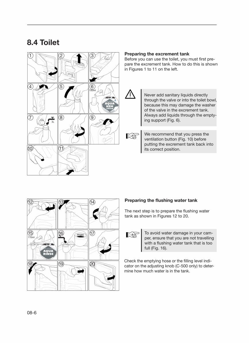
08-6
8.4 ToiletPreparing the excrement tankBefore you can use the toilet, you must first pre-pare the excrement tank. How to do this is shown in Figures 1 to 11 on the left.
Never add sanitary liquids directly through the valve or into the toilet bowl, because this may damage the washerof the valve in the excrement tank.Always add liquids through the empty-ing support (Fig. 6).
We recommend that you press the ventilation button (Fig. 10) before putting the excrement tank back into its correct position.
Preparing the flushing water tank
The next step is to prepare the flushing water tank as shown in Figures 12 to 20.
To avoid water damage in your cam-per, ensure that you are not travelling with a flushing water tank that is too full (Fig. 16).
Check the emptying hose or the filling level indi-cator on the adjusting knob (C-500 only) to deter-mine how much water is in the tank.
1 2 3
4 5 6
7 8 9
10 11
12 13 14
15 16 17
18 19 20

08-7
Using the toilet
The toilet can be used when the valve is either open or closed. To open the valve, turn the con-trol knob counter-clockwise or push the lever to the left (depending on your model).
Never leave any water in the bowl when the toilet is not being used, because this will not prevent un-pleasant odours.
Flush the toilet by pressing the flush knob for several seconds. Shut the valve every time you have finished using the toilet.
Emptying the excrement tank
The excrement tank has a capacity of approx. 19 litres. It must be emptied when the filling level indicator lights up red. Once this lights up, the tank can be used no more than two times.Ensure that the valve is closed, open the Porta Potti flap and follow the instructions shown in Figures 21 to 31 on the left.
To empty the tank without spraying, press the ventilation button while you are emptying the contents of the tank. Only press the ventilation but-ton when the emptying support is in a downward position!
Empty the excrement tank only in special places for sanitary disposal.
Please refer also to the manufacturer's operating manual, included in this package.
21 22 23
24 25 26
27 28 29
30 31

08-8
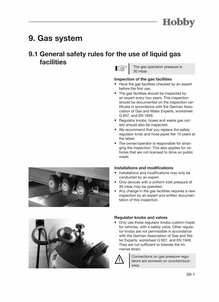
09-1
9. Gas system
9.1 General safety rules for the use of liquid gas facilities
Inspection of the gas facilities• Have the gas facilities checked by an expert
before the first use.• The gas facilities should be inspected by
an expert every two years. This inspection should be documented on the inspection cer-tificate in accordance with the German Asso-ciation of Gas and Water Experts, worksheet G 607, and EN 1949.
• Regulator knobs, hoses and waste gas out-lets should also be inspected.
• We recommend that you replace the safety regulator knob and hose pipes fter 10 years at the latest.
• The owner/operator is responsible for arran-ging the inspection. This also applies for ve-hicles that are not licensed to drive on public roads.
Installations and modifications• Installations and modifications may only be
conducted by an expert.• Only devices with a uniform inlet pressure of
30 mbar may be operated. • Any change in the gas facilities requires a new
inspection by an expert and written documen-tation of this inspection.
Regulator knobs and valves• Only use those regulator knobs custom-made
for vehicles, with a safety valve. Other regula-tor knobs are not permissible in accordance with the German Association of Gas and Wa-ter Experts, worksheet G 607, and EN 1949. They are not sufficient to tolerate the im-
mense strain.
The gas operation pressure is30 mbar.
Connections on gas pressure regu-lators are screwed on counterclock-wise.

09-2
Before first use• Ventilation openings should remain unob-
structed.• If necessary, remove snow from the flue.• Remove any dirt and snow/debris mixture
from the suction openings under the vehicle floor; otherwise, the levels of carbon mon-
oxide could increase to dangerous levels.• The safety ventilation openings may not be
closed.• We recommend that you keep a fire extin- guisher that uses drying powder, with a capa-
city of at least 1 kg, by the entry door, as well as a fire blanket by the cooker. Ensure that everyone is familiar with the fire prevention measures on site (see also 2.1 General infor-mation).
Read the operating instructions from the manufacturer carefully.
Never use portable cooking or hea-ting equipment, except for electrical heating equipment (note the power consumption), but not radiant hea-ters, because these may cause a fire or risk of suffocation.
• Pressure regulators must have a fixed output pressure of 30 mbar. The requirements of EN 12864, Appendix D, apply accordingly. The regulator must have a rate of flow of 1.2 kg/h.
• Connect the regulator knobs very carefully by hand. do not use keys, pliers or similar tools.
• Use the de-icing system (Eis-Ex) for the regulator knobs when the temperature drops below 5° C.

09-3
The camper is equipped with propane gas facilities. These facilities opeate the following devices:- cooker- refrigerator- heating element- warm water boiler, if necessary- special equipment, if necessary- baking oven, if necessary
9.2 Gas supply
2
1
3 4
5
Bottle containerThe gas bottle container holds two 11 kg pro-pane cylinders j. Via a safety regulator k, the gas bottles are attached by a hose m to the supply line n. Each bottle is fastened by two separate belts l to the floor of the gas bottle container and the wall at the front end of the camper.
Rules for the gas-bottle container:• Before every trip, check that gas bottles are
securely fastened. Place them in an upright position and shut the valves.
• Re-lash all loose belts.• Using a leak indicator, inspect the regulator
connection for leaks every time you change a bottle.
• The gas-bottle container is not suitable for transporting accessories (e.g. outer tent).
• The main shutoff valves on the gas bottles must always be easily accessible.
• The ventilation of the gas-bottle container (gap between the bottom of the bottle contai-ner and the front wall) must not be closed.
• Lock the gas-bottle container to prevent un-authorised people from obtaining access.
Gas bottles may only be carried inthe gas-bottle container.
Gas bottles must be closed whene-ver you are driving.

09-4
Changing gas bottles
• Open the flap of the gas-bottle container.• Shut the main shutoff valve on the gas bottle.• Manually unscrew the gas pressure regulator
and gas hose from the gas bottle (left-handed thread).
• Loosen the belts and remove the gas bottle.• Put full gas bottle back in the bottle container.• Lash belts securely. • Manually screw gas pressure regulator and
gas hose onto the gas bottle (left-handed thread).
• Close the lid of the gas-bottle container.
Never smoke or light open fires when changing gas bottles. After changing bottles, check whether gas is escaping from the points of attachment by spra-ying these with a leak indicator.
Shutoff spigots and valvesThe gas circulation to the corresponding device can be cut off with these spigots. The spigots are marked with stickers for the corresponding devices.
Place of installation of gas shutoff spigots• These are located in the kitchen in the upper
drawer.
Rules for shutoff spigots and valves:• Close all spigots on gas-powered devices
during the drive. • The gas shutoff spigots shown on the adjoi-
ning photos are closed. To open the valves, they must be turned to a vertical position.
• No inflammable devices may be in operation when filling the petrol tank of the base vehi-cle, on ferries and in the garage.
If you suspect a leak in the gas system, you must immediately close all the shutoff spigots in the camper and the gas bottle valves in the bottle compartment.
If you suspect leaks, have your dealer or another expert inspect for leaks.
Such an inspection may never be conducted in the presence of open flames.
The symbols on the gas shutoff spigots have the following meanings:
Heating element
Baking oven
Gas range
Refrigerator

09-5
The external gas socket (optional) can be used for connecting gas devices (such as the barbe-que).
When hitching, the plug connection is plugged into the safety coupling. The plug connection can only be hitched when the emergency shutoff valve j has been closed. Push back the clutch sleeve to undo the safety latch.
9.3 External gas socket
1
• The operating pressure of devices to be connected must be 30 mbar.
• Maximum performance of devices to be connected: 1.5 kW
Shut the cap k of the valve opening when the clutch is not in use.
2

09-6

10-1
10. Built-in devices
10.1 General information In this chapter, you will find information on the devices that have been built into the camper. This information refers only to the operation of these devices. To some extent, the devices described are special accessories. For further information on the individual built-in devices, please refer to the separate operating instruc-tions that have been included in the blue service bag found in the vehicle.
Built-in devices may only be repaired by specialists.
Only the device manufacturer‘s origi-nal spare parts may be used for main-tenance and repair work.
Any changes to the built-in devices as well as non-compliance with the rules for use will cause the guarantee to become void and lead to the exclusi-on of liability claims. Furthermore, the operating licence for the device will become void and, in some countries, this means that the operating licence for the vehicle is also void.
Please also refer to the instructions in Chapter 9 for operating gas devices, gas regulators and gas bottles.
Please observe the instructions in Chapter 7 for operating electrical devices.
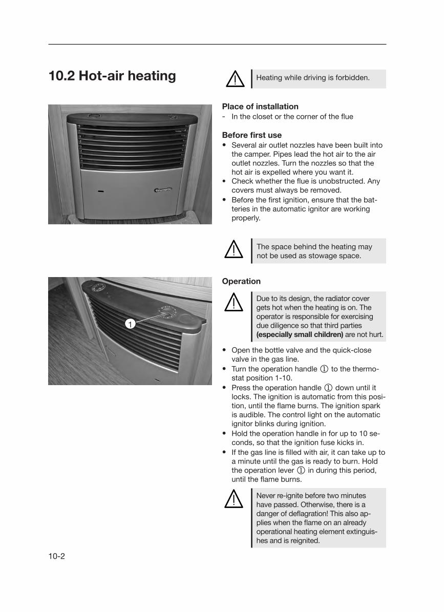
10-2
10.2 Hot-air heating
Place of installation- In the closet or the corner of the flue
Before first use• Several air outlet nozzles have been built into
the camper. Pipes lead the hot air to the air outlet nozzles. Turn the nozzles so that the hot air is expelled where you want it.
• Check whether the flue is unobstructed. Any covers must always be removed.
• Before the first ignition, ensure that the bat-teries in the automatic ignitor are working properly.
Heating while driving is forbidden.
Never re-ignite before two minutes have passed. Otherwise, there is a danger of deflagration! This also ap-plies when the flame on an already operational heating element extinguis-hes and is reignited.
The space behind the heating may not be used as stowage space.
Operation
• Open the bottle valve and the quick-close valve in the gas line.
• Turn the operation handle j to the thermo-stat position 1-10.
• Press the operation handle j down until it locks. The ignition is automatic from this posi-tion, until the flame burns. The ignition spark is audible. The control light on the automatic ignitor blinks during ignition.
• Hold the operation handle in for up to 10 se-conds, so that the ignition fuse kicks in.
• If the gas line is filled with air, it can take up to a minute until the gas is ready to burn. Hold the operation lever j in during this period, until the flame burns.
1
Due to its design, the radiator cover gets hot when the heating is on. The operator is responsible for exercising due diligence so that third parties (especially small children) are not hurt.

10-3
• If the flame extinguishes again, re-ignition takes place during the closing phase of the fusible cut-out of the ignition safety switch (approx. 30 seconds).
• If no flame is ignited, the automatic ignitor k will continue to work until the operation handle j is switched to “0”.
2
1
Changing batteries on the automatic ignitor kIf you cannot hear any ignition sparks or only hear them in intervals of more than one second, then you must insert a new battery.
• Ensure that the heating has been switched off.
• Remove the radiator cover (see Truma opera-ting instructions).
• Push the cover of the battery compartment up and exchange the battery (take special note of plus and minus).
• Close the battery compartment.• Use only a temperature-resistant (+70° C) and
leakproof mignon battery.
During initial operation of the heating system, there will be a slight nui-sance caused by smoke and odours. Immediately turn the operating handle j on the heating to position „10“ and set the circulation fan to the highest position. Open all doors and windows and air the camper well. The smoke and odours will disperse after a short while.
To shut off• Turn the operation handle j to position "0".
The automatic ignitor is thereby shut off.• If necessary, let the circulation fan continue to
run for a while.• Close the bottle valve and the quick-close
valve if the unit is not used for a longer period of time.
Insert new batteries before the begin-ning of each heating season.
Also note the separate operating instructions from the manufacturer.

10-4
Circulation fan
1
1
Fig. 1
Fig. 2
Fig. 3
The heating system in your camper has been fitted with a recirculation air system which distri-butes the hot air throughout the entire interior by means of several air vents. The air vents can be turned and opened individually, enabling the hot air to escape with the corresponding intensity to where it is required. The desired heating power can be regulated by using the adjusting knob j. The adjusting knob j is located on the reflecting panel of the heater (Fig. 1 and 2).
If less air is circulated or the noise from the blower increases, this means that the ventilation wheel is dirty. As a rule, the heating elment casing and vacuum pipe should be removed from the heating element approximately every 500 hours of operation and the ventilation wheel should be gently cleaned with a thin brush.
Always turn on the circulation fan when you set the heater to positions 3, 4 or higher. Otherwise there is a danger that the heater will overheat.
Adjustment by hand• Set the switch n to position (1) (Fig. 3).• Adjust the desired level via the turning knob m.
To turn off• Set switch n to position k.
Automatic operation• Set switch n to position l. The level ad-
justs itself continuously to the corresponding release of warmth by the heating element. The highest level can be limited by the turning knob. The adjustment between this value and the slow-running setting takes place automa-tically.
32
4
5

10-5
10.3 Electric auxiliary heatingThe electric auxiliary heating (Ultrahe-at) operates only when the camper is connected to the 230V mains supply.
The electric auxiliary heating is integrated in the hot-air heating system. This allows for three pos-sible heating methods:- just the gas heater- gas heater + electric heater- just the electric heaterThe electric auxiliary heating allows you to heat up the vehicle more quickly. It has three power settings:- 500 W- 1000 W- 2000 W
Before switching on the Ultraheat, please ensure that the fuse protection of the electrical supply at the camp-site corresponds to the power setting you have selected.
During operation, the reflecting panel of the heater will get very hot in some places.
To switch on• Set the rotary switch to the desired power set-
ting (green indicator light will light up during „Operation“).
• Set the desired room temperature using the rotary switch.
To switch off• Use the rotary switch to turn off the heater.
To distribute hot air evenly and quic-kly and ensure that the surface tem-perature on the heater is reduced, the heater should be operated only when the circulation fan has been switched on.
Ultraheat
230 V ~
2000
500
1000
13
57
9

10-6
10.4 Electrical floor heatingThe heating system is located in the middle walking space of the floor. It is 60 cm wide; the length depends on the type of vehicle. This he-ating system is not meant to heat the room; in-stead, it reduces the loss of heat via the floor.
To turn on the 24 V floor heatingYou will find the switch on the service panel. The floor heating operates only when the caravan has been attached to a 230 V power supply.
Technical dataVoltage 24V~ from its own 230V/24V transfor-mer.Depending on the length of the camper, power consumption lies between 150W and 320W.
To prevent local hot spots, do not place objects for a longer period of time on the floor if the floor heating system has been turned on. Do not drill any holes in the floor or screw in any screws.

10-7
10.5 Hot-water heating systemYou are not permitted to operate the hot water heater while driving.
The Compact 3010 LPG heater is a hot-water heating system which heats hot water separately (contents: 8.5 l). It is possible to heat up the he-ating system without filling the hot-water heater with fresh water.
Location• In the wardrobe.
Important information• Please read the separate operating instructions
carefully before initial operation of the heating system.
• Always turn off the main switch for the heating system whenever the vehicle is not in use.
• If there is danger of frost, always drain off the fresh water in the hot-water heater.
• You may not start the heating if the device has not been filled with glycol.
• To make the best possible use of the convection principle, the air must not be prevented from circulating throughout the camper, e.g. behind the back cushions, winter ventilation slots, in the bed frame and behind the stowage cupboards.
Modes of operation• LPG operation• Heating cartridge operation (230 V)• Combined LPG and heating cartridge operation
Function modes• Water heating• Heating and water heating• Heating
Check the amount of liquid in the ex-pansion tank at regular intervals. When the heating is off, the liquid should be approx. 1 cm above the "Min" mark.

10-8
For further detailed information on operation, handling and maintaining the hot-water heating system, please refer to the separate operating in-structions for “Alde Compact 3010”.
blinkarblinkt
blinkarblinkt
To start the hot water heater
Press the button with the arrow until the „Off“ sign (main switch) blinks on the display.
Press the +/On button. The „On“ sign (main switch) will blink on the display.
Operating deviceWhen in the idle position, the device shows which heating functions have been activated; the background lighting of the display is off. After two minutes, the operating device automatically switches from the set position to the idle position if no button has been pressed or if the idle positi-on has been set using the arrows.
Begin by pressing any button. The background lights up and those functions that can be set will start to blink. Use the arrows to select the func-tion you wish to set. Settings are saved automa-tically.

10-9
blinkarblinkt
blinkarblinkt
blinkarblinkt
Press the -/Off button. The „Off“ sign (main switch) will blink on the display.
The settings are now complete. The „Off“ sign (main switch) is shown on the display when the control unit is in an idle state.
Setting the desired temperature
Press the button with the arrow until the symbol for temperature selection blinks. The tempera-ture shown is the temperature presently set (in this case: 22.0° C).
Raise the temperature by pressing on the +/On button. Lower the temperature by pressing on the -/Off button. In the illustration, the tempera-ture has been set to 25.0° C.
The settings are complete and the heating will run until the set temperature has been reached.
blinkarblinkt
The settings are now complete. The „On“ sign (main switch) is shown on the display when the control unit is in an idle state.
To shut off the hot water heater
Press the button with the arrow until the „On“ sign (main switch) blinks on the display.

10-10
blinkarblinkt
blinkarblinkt
blinkarblinkt
Turn on the hot water by pressing on the +/ON button. „ON“ appears on the display next to the temperature.
The symbol for hot water is shown when the control unit is back in an idle state.
Press the button with the arrow until the symbol for hot water blinks. „ON“ appears on the display next to the temperature.
Turn off the hot water by pressing on the -/Off button. „OFF“ appears on the display next to the temperature.
The symbol for hot water disappears when the control unit is back in an idle state.
Hot water
Press the button with the arrow until the symbol for hot water blinks. „OFF“ appears on the dis-play next to the temperature.
blinkarblinkt

10-11
Activate heating with gas by pressing on the +/On button. „ON“ appears on the display next to the temperature.
The symbol for heating with gas is shown on the display when the control unit is in an idle state again.
Press the button with the arrow until the symbol for heating with gas blinks. „ON“ appears on the display next to the temperature.
Deactivate heating with gas by pressing on the -/Off button. „OFF“ appears on the display next to the temperature.
The symbol for heating with gas disappears when the control unit is in an idle state again.
blinkarblinkt
blinkarblinkt
blinkarblinkt
Heating with gas
Press the button with the arrow until the symbol for heating with gas blinks. „OFF“ appears on the display next to the temperature.
blinkarblinkt

10-12
blinkarblinkt
blinkarblinkt
Select the power setting (1kW, 2kW or 3kW) by pressing the +/On or the -/Off button. In the illus-tration, the 3kW power setting has been selected (some heaters are only equipped with 1-2kW).
The symbol for electric heating is shown when the control unit is back in an idle state.
Press the button with the arrow until the symbol for electric heating blinks.
Switch the electric heating off by pressing the -/Off button until all of the power settings have been deleted. „OFF“ appears on the display next to the temperature.
The symbol for electric heating disappears when the control unit is back in an idle state.
Electric heating
Press the button with the arrow until the symbol for electric heating blinks. „OFF“ appears on the display next to the temperature.
blinkarblinkt
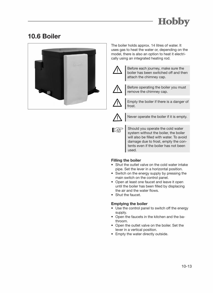
10-13
10.6 BoilerThe boiler holds approx. 14 litres of water. It uses gas to heat the water or, depending on the model, there is also an option to heat it electri-cally using an integrated heating rod.
Before each journey, make sure the boiler has been switched off and then attach the chimney cap.
Before operating the boiler you must remove the chimney cap.
Empty the boiler if there is a danger of frost.
Never operate the boiler if it is empty.
Should you operate the cold water system without the boiler, the boiler will also be filled with water. To avoid damage due to frost, empty the con-tents even if the boiler has not been used.
Filling the boiler• Shut the outlet valve on the cold water intake
pipe. Set the lever in a horizontal position.• Switch on the energy supply by pressing the
main switch on the control panel.• Open at least one faucet and leave it open
until the boiler has been filled by displacing the air and the water flows.
• Shut the faucet.
Emptying the boiler• Use the control panel to switch off the energy
supply.• Open the faucets in the kitchen and the ba-
throom.• Open the outlet valve on the boiler. Set the
lever in a vertical position.• Empty the water directly outside.

10-14
Operating on gas• Remove the chimney cap.• Open the gas bottle and the emergency shut-
off valve on the gas pipe.• Use the rotary switch on the control panel to
switch on the boiler. The green control light will shine.
• Use the rotary switch to set the desired tem-perature (approx. 30° C – 70° C).
Operating on electricity• Use the control panel to switch on the
boiler. The control light will shine.
When operating on electricity, it is not possible to preselect the water temperature. This is automatically set to approx. 70° C.
Switching off the boiler• Use the rotary switch to turn off the boiler.• Attach the chimney cap and close the emer-
gency shutoff valve and, if necessary, the gas bottle (only when operating on gas).
30
4050
60
70
Boiler
Boiler EL
230 V ~
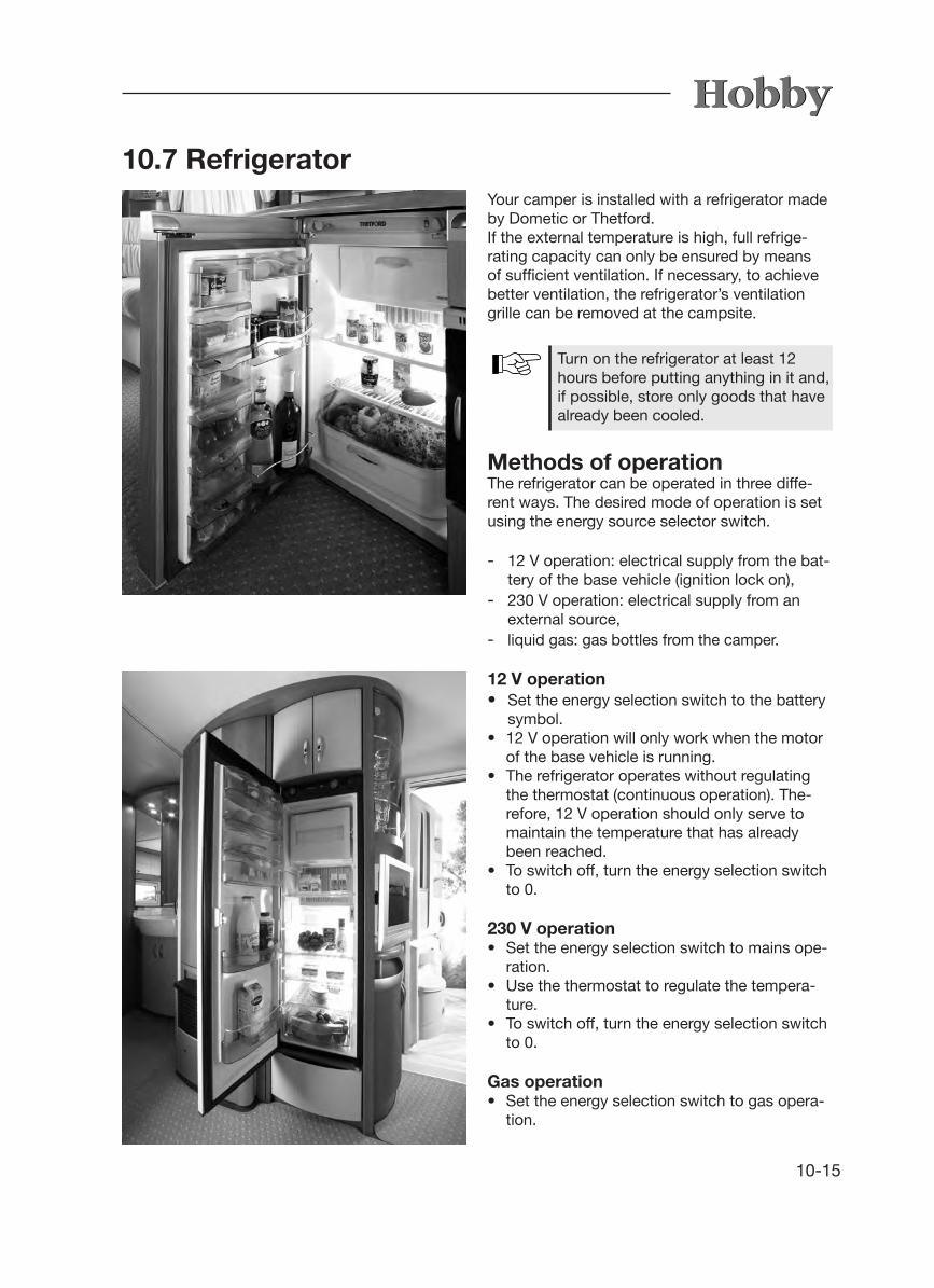
10-15
Your camper is installed with a refrigerator made by Dometic or Thetford. If the external temperature is high, full refrige-rating capacity can only be ensured by means of sufficient ventilation. If necessary, to achieve better ventilation, the refrigerator’s ventilation grille can be removed at the campsite.
Methods of operationThe refrigerator can be operated in three diffe-rent ways. The desired mode of operation is set using the energy source selector switch.
- 12 V operation: electrical supply from the bat-tery of the base vehicle (ignition lock on),
- 230 V operation: electrical supply from an external source,
- liquid gas: gas bottles from the camper.
12 V operation• Set the energy selection switch to the battery symbol.• 12 V operation will only work when the motor
of the base vehicle is running.• The refrigerator operates without regulating
the thermostat (continuous operation). The-refore, 12 V operation should only serve to maintain the temperature that has already been reached.
• To switch off, turn the energy selection switch to 0.
230 V operation• Set the energy selection switch to mains ope-
ration.• Use the thermostat to regulate the tempera-
ture.• To switch off, turn the energy selection switch
to 0.
Gas operation• Set the energy selection switch to gas opera-
tion.
10.7 Refrigerator
Turn on the refrigerator at least 12 hours before putting anything in it and, if possible, store only goods that have already been cooled.

10-16
• Open the main shutoff valve on the gas bottle and the gas shutoff spigot marked “refrigerator”.
• Turn the thermostat up full and keep it pressed down. The refrigerator will either ignite automa-tically or by using the knob for manual ignition (depending on your model).
• When it is ignited, let go of the thermostat. Re-peat the previous step if it has not ignited.
• Use the thermostat to regulate the cooling effici-ency.
• To switch off, turn the energy selection switch to 0.• Close the main shutoff valve on the gas bottle
and the gas shutoff spigot marked “refrigerator”.
Lock on the refrigerator door
The refrigerator door must always be kept shut and locked while driving.
Lock on the Dometic model
There is an automatic lock on the door of the 'Slim Tower' and the door of the refrigerator made by Thetford.If you close the refrigerator and press the door firmly shut, it will lock automatically.
An additional safety catch is located underneath the Thetford models.
With the exception of the 'Slim Tower', Dometic refrigerators are secured by means of a bolt lock on the door.
The refrigerator door can be locked in two settings- closed door while driving and when the refri-
gerator is in use;- slightly opened door as a ventilation position
when the refrigerator has been turned off.
To prevent mould and unpleasant odours from arising, also lock the refrigerator door in the ventilation position whenever the refrigerator has been turned off.
Lock on the Thetford model

10-17
Separate freezer compartmentIf the outside temperature and the rate of humi-dity are very high, drops of water may form on the metal frame of the separate freezer compart-ment. For this reason, it has been fitted with a frame heater(175 litre Dometic refrigerator only).If the outside temperature and the rate of hu-midity are very high, switch the frame heater on by pressing j. This helps to avoid corrosion. When the frame heater is on, the control light k will shine.
1
2
• Food should always be stored in closed con tainers, aluminium foil or similar materials.• Never store warm food in the refrigerator; always let it cool off first.• Goods that might emit readily volatile or flam mable gases must not be stored in the refri gerator.• Always store perishable food directly next to the cooling fins or as close to the bottom of the refrigerator as possible.
Storing food
The freezer compartment is suitable for making ice cubes or for storing frozen food for a short period of time. It is not suitable for freezing food.
It is not suitable for freezing food nor for the proper storage of medication.
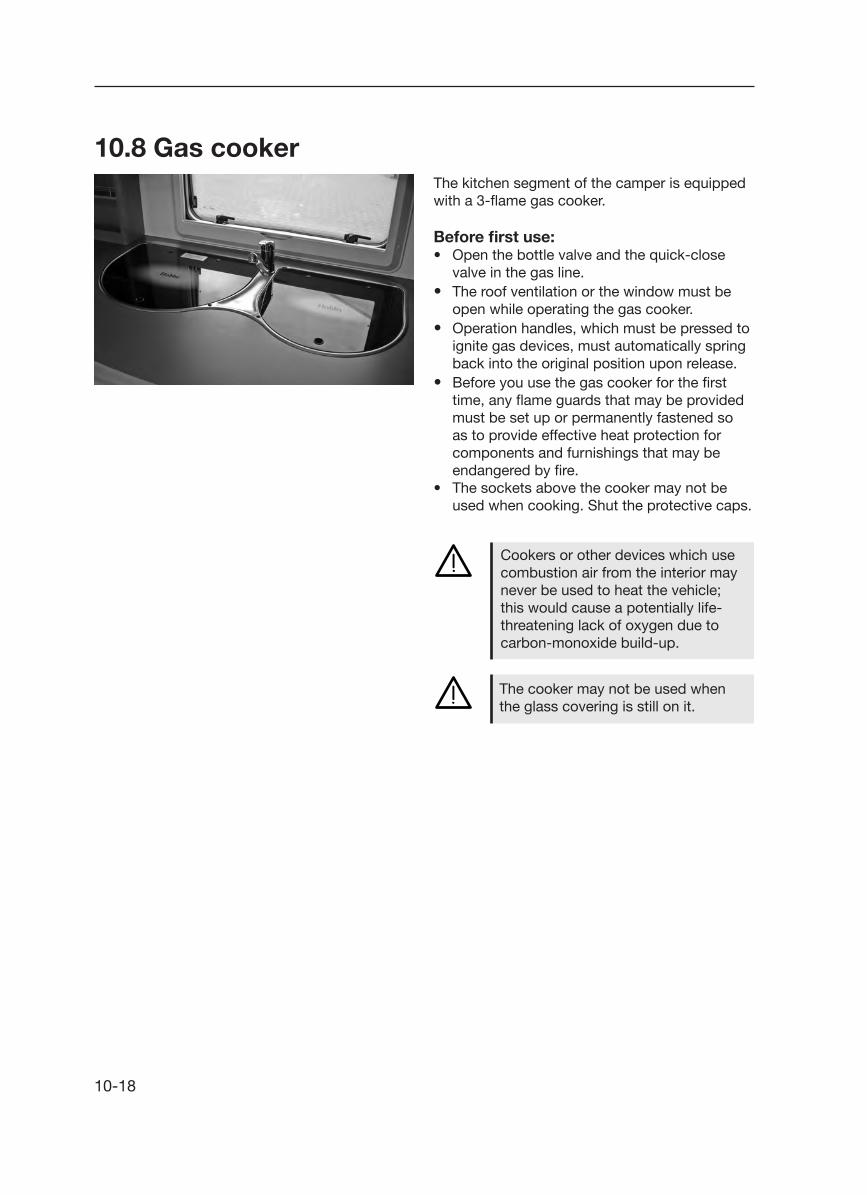
10-18
10.8 Gas cookerThe kitchen segment of the camper is equipped with a 3-flame gas cooker.
Before first use:• Open the bottle valve and the quick-close
valve in the gas line.• The roof ventilation or the window must be
open while operating the gas cooker.• Operation handles, which must be pressed to
ignite gas devices, must automatically spring back into the original position upon release.
• Before you use the gas cooker for the first time, any flame guards that may be provided must be set up or permanently fastened so
as to provide effective heat protection for components and furnishings that may be
endangered by fire.• The sockets above the cooker may not be
used when cooking. Shut the protective caps.
Cookers or other devices which use combustion air from the interior may never be used to heat the vehicle; this would cause a potentially life-threatening lack of oxygen due to carbon-monoxide build-up.
The cooker may not be used when the glass covering is still on it.

10-19
2
Operation• Open the cover j.• Set the turning knob k of the desired burner
in the ignition position (large flame) and press.• Ignite the burner with gas lighter fluid, a
match and/or lighter. (Spinflo cooker: press the igniter l.)• Hold the turning knob k in for an additional
10-15 seconds.• Release the turning knob k and position it to
the desired setting (large or small flame).• If the ignition is unsuccessful, repeat the pro-
cess from the beginning.
Use potholders or mitts when hand-ling hot pots, pans and similar ob-jects. Danger of injury!
Keep the cover j open after coo-king for as long as the burners are still giving off heat.
Do not store easily inflammable objects such as dish towels, napkins, etc., near the cooker. use the protec-tive device on the cooker at all times when cooking. Danger of fire!
Never allow gas to escape without burning. Danger of explosion!
2 3
"Spinflo" cooker
1

10-20
10.10 Oven• The ventilation openings on the
oven must never be closed.• Only operate the oven when it has
been connected to the 230 V mains (automatic ignition).
• A skylight or window must be opened when operating the oven.
• The oven door must remain open while igniting the oven.
• If it has not ignited, repeat this pro-cedure from step 1.
• Should the flame on the burner ac-cidentally be extinguished, turn the switch back to the neutral position and leave the burner off for at least one minute before igniting it again.
10.9 Fume hoodAs an option, the kitchen can be fitted with a fume hood. The built-in fan blows kitchen odours directly outside.
Clean the filter of the fume hood regu-larly, as it collects the fat from kitchen odours.
The Prestige models have been outfitted with the Dometic fume hood CK155. Please refer to the separate operating instructions.
Fume hood in the Prestige models
The kitchen light, which is operated via the con-trol panel, can also be switched on using the left button.
Press the right button to turn on the fume hood. Hold the fan button firmly to select the speed of the fan from among 15 different speeds.

10-21
Turning on the oven• Switch on the 12 V power supply using the
main switch on the control panel.• Open the main shutoff valve on the gas bottle
and the gas shutoff spigot marked “oven”.• Open the oven door completely.• Position the baking tray or grill so that it is not
in direct contact with the flame.• Press the switch lightly and set it to the
desired ignition position (oven or grill, if availa-ble).
• Press the switch. Gas flows to the burner and the flame will ignite automatically.
(Spinflo oven: must be ignited manually.)• Press the switch for several seconds until the
safety pilot valve keeps the gas flow open.• Let go of the switch and turn it to the desired
setting (oven only).• Close the oven door carefully to prevent the
flame from extinguishing.
Turning off the oven• Turn the switch to the neutral position. The
flame will extinguish.• Close the main shutoff valve on the gas bottle
and the gas shutoff spigot marked “oven”.
• Never operate the oven when it is empty (i.e., without food that is to be heated).
• The grill (special equipment; not part of standard delivery) should never be used for longer than 25 minutes and only operated when the oven door is open.
• Never use the oven to heat the camper.
"Spinflo" oven

10-22
10.11 MicrowaveAs an option, the kitchen of your camper may be outfitted with a 230 V microwave, which is installed behind a flap in the kitchen wall cabinet. This device is suitable for defrosting, heating up and cooking food for your personal use.
Leave the flap open when operating the microwave. Risk of overheating!
To operate• Turn the upper knob to the desired level of power j . • Select the desired cooking time by turning the lower knob, taking the recommendations into account k .• The microwave will automatically start to heat up once the time and level of power have been entered.• The device will make a beeping signal when the time has expired.• When not in use, please set the time (2) to"0".
Please refer to the separate operating instructions for safety instructions and detailed information on how to ope-rate, use and care for the microwave.
1
2

11-1
11. Accessories Note the detailed operation instructions, instal-lation instructions and circuit diagrams from the manufacturers when using accessories. These are located in your service package.
• Any changes to the status of the camper as delivered by the manufacturer may endanger driving performance and roadworthiness.
• Anyaccessories,add-ons,modificationsormounted parts that have not been approved by HOBBY may cause damage to the vehicle and impair its roadworthiness. Even if an expertise, general type approval or design approval has been provided for these parts, this does not ensure the orderly condition of the product.
• HOBBY cannot accept liability for any damages caused by parts or changes that have not been approved by HOBBY.
The following table includes a list of weights for accessories. If these parts are carried in or on the camper and are not included in the standard scope of delivery, they must be taken into consideration when determining the full load.
Object Weight [kg] Object Weight [kg]
50 l instead of 25 l built-in fresh water tank 28.07-zone cold foam mattress 2.9Additional roof bonnet 400 x 400 3.4Additionalserviceflap 0.5Air-conditioning HobbyCool 25 (Dometic) 25.0Air-conditioning Truma Saphir Comfort 20.0Alde hot-water heater Compact 3010 27.5AL-KO spare tire holder EH 1 Model C 7.7Antenna mast Teleco 0.9Battery container 2.0Bed expansion for single beds 5.0Bedspread 1.5Bicycle carrier 6.8Boiler 15.0Bunk bed, 3-storey 15.0Car jack with box 6.0Charge controller incl. 600 VA electrical supply 2.8Children's bunk bed instead of centre seating arrangement 14.0City water connection 0.5Dinette instead of centre seating arrangement 8.5Dometic fume hood 3.0Drawbar anti-theft device Robstop 3.0External socket for gas 1.5Floor heating 4.0 - 6.0
Heavy-duty stanchions 1.6Increased load, single axle 0 - 24.0Increased load, tandem axle 16.0Laundry cupboard instead of shower 2.5LCD control panel 1.0Memory foam mattress 2.9Microwave 12.0Mover H SE / H TE 26.0Oven incl. light, grill and electric ignition 15.0Queen-size bed, crossways in the rear 8.0Rear panorama window 1.5Removable carpeting for de Luxe models 7.0 - 10.0Residual current device 0.3Self-sufficientpackage 29.0Sound system 11.0Spare tire incl. mount 20.0Tire repair kit 2.2Truma Airmix convenience package 1.0Truma electric auxiliary heating Ultraheat 2.0Truma electric boiler instead of therme 5.0Truma gas boiler instead of therme 15.0Truma gas/electric boiler instead of therme 16.0Truma hot-air system Isotherm 3.0UFK version 15.0UMF version 3.5Universal mount for LCD television 3.5

11-2

12-1
12. Maintenance and upkeep
12.1 Maintenance Maintenance intervalsfixed maintenance intervals apply to the camper and the devices installed in it.
Rules for maintenance intervals• Have the first maintenance performed by a HOBBY dealer 12 months after the initial registration.• Havve all further maintenance performed once annually at a HOBBY dealer.• Have all maintenance on built-in devices performed in accordance with the corres ponding maintenance intervals indicated in the operating instructions.
1
Greasing and oilingRegularly examine and grease the sliding parts and stationary parts of the undercarriage. If the camper is used seldom, yearly maintenance is required.
Rules for greasing and oiling• After every 5,000 kilometers driven, but at
least once a year, grease the swinging lever bearings on the turning rod spring axle unit.
• Movable parts such as pins and hinged parts on the hand brake lever and deflexion lever of the ramp should be oiled lightly.
HOBBY grants a 5-year guarantee on the absence of leaks in the camper in accordance with the guarantee condi-tions.The vehicle is to be presented to your HOBBY dealer once a year for inspec-tion. After 12 months, the first inspec-tion for leaks is free of charge.
The inspection of the gas facilities (subject to extra cost) is to be repea-ted every two years by a liquid gas expert. This inspection is to be con-ducted and certified in accordance with the German Association of Gas and Water Experts, worksheet G 607, and EN 1949. The operator is respon-sible for scheduling this inspection.
Replace safety regulator knobs and hoses after 10 years at the latest!

12-2
For safety reasons, the spare parts for heating devices must conform with the manufacturer's instructions. They must be installed by the manufacturer or an authorised representative.
Coupling ball on base vehicleEnsure that the coupling ball meets the required dimensions and is undamaged, clean and free of grease. When using dacromet-coated (dull silver anti-corrosion coating) as well as lacquered cou-pling balls, the coating must be removed com-pletely with sandpaper (200-240 grain) so that it does not create deposits on the friction lining. The metal surface of the coupling ball must be bright. A damaged or dirty coupling ball causes increased wear of the friction linings; a greasy one greatly diminishes the stabilization effect. Thinning solvents or spirit are both suitable for cleaning.
12.2 Drawgear
The camper's turning rod spring axle unit is equipped with compact wheel bearings. The cylinder hub, compact bearings and axle nuts form a closed unit. The compact bearings are free of maintenance due to their special grease.
The wheel brake may never be repositioned on the fixing lock or on the yoke end of the bars!Only reposition the wheel brake on the self-securing stationary hexago-nal nut!
You can find further guidelines in the operating instructions from the axle supplier.
2• Lightly grease the stationary parts on the case
of the overrunning equipment k after every 5,000 kilometres of driving.
IMPORTANT: The friction elements of the WS 3000 safety hitch may NEVER be oiled or greased.
• Check from time to time to ensure that the bea-ring surfaces of the thrust rod are not jammed.
• Clean and oil all movable and stationary parts regularly.

12-3
Changing the friction lining It is very easy to exchange the friction pads j when they are worn out. Messrs. Winterhoff offer a corresponding set of spare parts. Please note the detailed instructions for assembly in the manufacturer's spare part kit.
NoisesCertain noises can occur during the course of the drive; these noises, however, have no influence on the operative effectiveness of the tension ball coupler.
Possible causes of these noises can be:
1. a dacromet-coated coupling ball on the base vehicle.2. A galvanized or varnished coupling ball on the base vehicle.3. A damaged, rusty or dirty coupling ball on the base vehicle. 4. dirty friction elements jon the tension ball coupler.5. the towbar or tie rod in the linings of the over- running equipment are running dry.
HintsFor 1., 2. and 3.:Sand down the surfaces of the coupling ball and clean them with a thinning solvent or spirit.
for 4: Clean the surface of the friction elements with sandpaper (200-240 grain) and then clean with petroleum ether or spirit.
for 5:Use a lubricating nipple to grease the linings. Pull back the shock absorber and grease the bare towbar.
1
1
Tension ball couplerKeep the friction linings inside the tension ball coupler clean and free of grease (Fig. 5). When the friction linings are dirty, the surface can be cleaned with 200-240 grain sandpaper. Then clean with petroleum ether or spirit. All movable bearings and bolts are easy to grease. By regular upkeep and maintenance of your WS 3000, you increase its overall life span, function and safety.

12-4
12.3 Brakes Initial inspection
The wheel brakes that have been installed are drum brakes that do not adjust automatically. To ensure trouble-free brake performance, the wheel brakes must be adjusted regularly.
The brakes must first be inspected after you have driven 500 km. Have them inspected again after every 10,000 km of driving, but at least once every year. Inspections must be documen-ted in the KNOTT service manual by the autho-rised specialist who carries out the inspection. These documented reports are just as much a prerequisite for any possible guarantee claims as is the compliance with the regulations for main-tenance and upkeep.

12-5
12.4 Changing the taillight bulbsCarefully remove the protective caps with a screwdriver.
Now you can remove the taillight from the frame.
Remove the holder by loosening the screw.
The bulbs are now freely accessible.Put the taillight back together by repeating the process in reverse.
Remove the four fastening screws with a crosstip screwdriver.

12-6
12.5 Ventilation
12.6 Upkeep
Sufficient ventilation and de-aeration of the vehi-cle interior is essential to maintaining a com-fortable climate. In addition, corrosion damage from sweat residue can be avoided.
Sweat residue forms most readily- in tight spaces, - from the breath and perspiration of the passen gers,- by carrying in damp clothing,- when operating the gas cooker.
Ensure sufficient air circulation to pre-vent damage from the collection of sweat residue!
Cleaning the exteriorThe vehicle should not be washed more often than necessary.
Only wash the vehicle at specially designed wash sites.
Use cleaning solvents as sparingly as possible. Aggressive cleaners such as rim cleaner pollute our environment.
Do not use cleaners which contain solvents.
Rules for cleaning the exterior• Rinse the vehicle with a light stream of water.• Wipe the vehicle down with a soft sponge and typical shampoo solution. Rinse the sponge often in the process.• Afterwards, rinse with a great deal of water.• Dry the vehicle with a suede cloth.• Allow the vehicle to stand out in the open after washing to let it dry.

12-7
Cleaning with a high-pressure cleaner
Note the instructions for the high-pressure cleaner before washing the camper with it. Keep a minimum distance of 700 mm between the camper and the high-pressure nozzle.
Note that the water jet comes out of the cleaning nozzle with a great deal of pressure. Incorrect use of the high-pressure cleaner can damage the camper. The temperature of the water must not exceed 60° C.
Keep the water jet constantly moving during the entire washing process. The water jet must not be aimed directly at the clearance between the door frame and door leaf or the window frame and window leaf, electrical add-ons, pin-and-so-cket connectors, gaskets, sealing grill for refrige-rator or the roof bonnets. This can damage the vehicle or allow water to seep into the interior.
Thoroughly dry the light sockets, because water collects there easily.
Labels and exterior decorations should not be sprayed directly with a high-pressure cleaner, because they may come off.
Never use caustic cleaners or clea-ners which contain solvents.
Rules for waxing the surfaces• Treat the paint surfaces periodically with wax. Note the guidelines for use from the wax manufacturer.
Rules for polishing surfaces• In exceptional cases, treat damaged paint sur faces with polish. We recommend paste pol- ishes free of solvents.

12-8
Do not polish too often since polishing removes the top layer of paint. Fre-quent polishing causes more damage than it remedies.
Rules for treating tar and resin stains• Remove residues from tar and resin as well as other organic stains with petroleum ether or spirit.
Do not use aggressive solvents such as products containing esters or ketone.
Rules for damage repair• All damage should be repaired immediately to avoid further damage from corrosion. Con sult your HOBBY dealer.
UndercarriageThe undercarriage of the camper has been spe-cially coated. If the protective coating is dama-ged, repair it immediately. Coated areas should not be treated with spray oil.
ChassisShould salt adhere to the hot-dip galvanised chassis, it will damage it and may cause white rust. However, white rust is not a defect, but merely an optical impairment. After driving in winter or through salty water, the hot-dip galva-nised surfaces should be rinsed with clear water.
Windows and doorsWindow panes requires particularly careful treat-ment.
Rules for upkeep• Rub the insulation of doors and windows lightly with talcum.
The combustion air intake duct for the heating system is located underneath the floor of the vehicle. Under no cir-cumstances may liquid sprays, under-body protection or similar products be allowed to interfere with it.

12-9
Cleaning the interior
Rules for cleaning seat covers, upholstery covers and curtains• Clean seat covers with a soft brush or vacu- um cleaner.• Have heavily soiled upholstery covers, bed- spreads and curtains dry cleaned; do not wash them yourself!• Clean with the foam of a gentle detergent if required.
Rules for cleaning the carpet• Clean with a vacuum cleaner or brush.• If necessary, treat or shampoo with carpet foam.
Rules for cleaning PVC surfaces
• Clean the surface with a special solvent for PVC surfaces. Do not place carpets on wet PVC surfaces. Carpets and PVC surfaces could stick together.• Never use chemical cleaners or steel wool, because they will damage the PVC surface.
Sand and dust can damage the sur-face of a PVC surface that is walked on regularly. When in use, clean the floor daily with a Hoover or broom.
Talcum is available in auto specialty stores.
Do not use strong and aggressive cleaners which contain softeners or solvents!
• Only clean acrylic glass window panes with a clean, moist sponge and a soft towel. Dry cleaning can scratch the panes.

12-10
Do not use scouring cleaners in the toilet area either!
Rules for cleaning the toilet area• Clean with neutral liquid soap and a non- scouring cloth.• Do not use a vinegar concentrate to clean the toilet and the water system or to decalcify the water system. Vinegar concentrate can dam- age gaskets or parts of the system.• The rubber seals of the toilet should be cleaned
regularly with plain water and a lubricant for seals (not Vaseline or any other vegetable fats) should be applied. Applying this regularly to the washer of the valve and other seals in the toilet will ensure that they stay flexible and function longer.
Do not pour corrosive cleaners down the drain. Do not pour boiling water down the drain. Corrosive cleaners and boiling water will damage the drainpipes and siphon traps.
Rules for cleaning the sink• Only clean the sink with typical household cleaners or special stainless steel cleaners.
The following applies for built-in equipment:• Heating: remove all of the dust that has coll-
ected on the heat exchanger, base plate and fan wheel of the hot-air system at least once a year before the camper season begins. Clean the fan wheel carefully with a brush or small scrubber.
• The glycol mixture in the hot-water heating system should be replaced every two years, because certain properties such as protection against corrosion deteriorate.
Do not use scouring solvents or inten-sive cleaners since these can scratch the surface!
• Rub dry with a soft, dust-free cloth.• Use mild furniture polish.
Rules for furniture surfaces• Clean wooden furniture finishes with a moist cloth or sponge.
12-11
12.7 Winter Lay Up for the Camper
For many people, the camping season ends when the temperature starts to fall. Your camper must be properly prepared for its winter lay up.
The following general rules apply:• Only leave your camper in a closed space if it
is dry and well-aired. Otherwise, it is better to leave your camper in the open.
• Cover the safety coupling. Grease the brake linkage and winding stanchions.
• Jack up the camper if possible. Extend the levelling supports to relieve the burden on wheels and axles to some extent. If possible, use axle stands to support the chassis.
• Close all gas bottles and emergency shutoff valves.
• If you use an auxiliary battery (self-sufficient package), it should be disconnected; ideally, remove it and store it safe from frost. Check it about once a month to see if it is still charged; if not, charge it.
Remove all spray cans with cleaners and polishes from the vehicle after finishing the upkeep! Otherwise, there is a danger of explosion at temperatures over 50° C!
• The space behind the refrigerator should be hoovered and cleaned regularly. The ventilation grille should also be kept clean. The door seal should be rubbed once a year with talcum po-wer to keep it supple and the expandable fold should be checked for tears.
• The filter in the fume hood must be cleaned occasionally, because cooking fat collects there. We recommend that you use warm water with a bit of dishwashing liquid to clean it.

12-12
Wash the vehicle only in special places provided for this purpose.
Use cleaning materials sparingly. Aggressive cleansers, such as wheel rim cleaners, damage the environment.
The following applies for tanks and con-tainers:• Clean, disinfect, descale and completely em-
pty all water pipes and faucets. Leave faucets open.
• Clean the fresh water tank and empty it by unscrewing the overflow pipe.
• Clean and empty the waste water tank.• Clean and empty the toilet flushing tank and
the excrement tank. Clean the toilet valve, apply a lubricant for seals and leave it open.
• Completely empty the therme/boiler.• If your camper is equipped with a hot-water
heater: rinse the water heater thoroughly and empty all of the water.
The following applies for the external structure:• Wash the camper thoroughly.• Check the vehicle for damages to the varnish
and other damages. If necessary, repair these damages and carry out any other necessary repairs.
• The exterior should be treated with wax or a special polish for varnish.
• Use a protective agent to protect the metal parts of the chassis against rust.
• Check the undercarriage for damage and, if necessary, repair it.
• Use a special cleaner for cleaning the plexig-lass windows, because normal window clea-ner makes the material cracked and brittle.
• Rub an acid-free rubber cleaning agent onto the seals around windows, doors and service flaps to keep them supple.
• Ensure that no water can get into the venting on the floor, heating system and refrigerator venting (mount winter covers).

12-13
With regard to camping in winter, we recommend that you optimize your camper to meet your personal requi-rements. Your Hobby dealer will be pleased to advise you.
12.8 Winter Operation Your camper has been designed to allow you to use it in winter.
The following applies for heating:• Both the air intake as well as the exhaust gas
openings of the heating system must be kept free of snow and ice (if necessary, use flue extensions).
• It takes longer to heat up the camper in winter, especially to heat hot water.
• Do not let the interior cool down completely when you are away or at night; set the heating to low and leave it on.
The following applies for the interior fittings:• Clean the interior of your camper. Hoover
carpets, cushions and mattresses. If possible, store them outside the camper. Otherwise, place them in such a way inside the vehicle that they do not come into contact with con-densation.
• Use soapy water to clean linoleum and smooth surfaces.
• Empty and clean the refrigerator. Leave the refrigerator door open.
• After cleaning them, leave stowage spaces, cupboards, drawers and furniture flaps open to facilitate air circulation.
• Leave vents for forced ventilation open. If the camper is kept in a closed space, you can leave the skylight open.
• Air the camper thoroughly every four to six weeks when the weather is dry.
• Set up a dehumidifier (such as salt) inside the camper and dry the granulate or change it regularly.
Please also refer to the information given by the manufacturers of built-in devices regarding winter.

12-14
If, despite all of these measures, con-densation forms somewhere, simply wipe it away.
The following applies for containers:• If the interior is sufficiently heated, the fresh
water tank, water pipes and therme/boiler should not freeze. Fill all of the water contai-ners only after the interior has been thoroughly heated.
• Since waste water is collected outside the ve-hicle, add antifreezer or common salt to it. The drain cock of the sewage pipe must be kept clear.
• The toilet can be used normally, even in cold weather, as long as the interior of the camper is heated. If there is a danger of frost, both the excrement and the flushing water tanks should be emptied.
The following applies for ventilation:During operation in winter, condensation is caused when using the camper in low tempera-tures. Sufficient ventilation is extremely impor-tant to ensure that the quality of the air inside the camper is good and to avoid damages to the vehicle caused by condensation.
• Do not shut vents for forced ventilation.• Set the heating to maximum power when he-
ating up the camper. Open stowage spaces, cupboards, drawers, furniture flaps, curta-ins, shades and plissés. This enables you to achieve optimum ventilation and de-aerating.
• Only heat the camper when the recirculation air system is switched on.
• Every morning, air all of the cushions, mattres-ses and stowage spaces and dry any damp spots.
• Air thoroughly with fully opened doors and windows several times a day.
• If the outside temperature is under 8° C, win-ter covers should be mounted over the venti-lation grilles of the refrigerator.
• The camper uses considerably more gas in winter than in summer. Two 11 kg bottles of gas will be used up in just under one week.
• Therefore, should you stay longer in one place, it is worthwhile to set up an outer tent. It will help to acclimatise the camper and keep the dirt out.

13-1
13. Waste disposal and environmental protection
13.1 The environment and mobile travel
Environmentally sound use
By nature of their activities, camper users bear a considerable responsibility towards the environ-ment.Therefore, you should always use your camper in an environmentally sound manner.
Rules for environmentally sound use• Do not interfere with the quietude and cleanli ness of nature.• Dispose of waste water, faeces and trash properly.• Act as a role model, so that campers are not stereotyped as environmental polluters.• If you plan to stay longer in cities and muni- cipalities, please park in an area that is speci- fically marked for trailer combinations. Find out in advance where these areas are located.
Rules for waste water disposal• Only collect waste water in the built-in tanks or, if absolutely necessary, in similarly suitable containers!• Never dispose of waste water in greenery or in gullies! Street sewer lines often do not lead to waste water treatment plants.• Empty the waste water tank as often as possible, even if it is not yet full (for hygienic reasons). If possible, rinse the waste water tank out with fresh water each time after emptying.
Only empty the faeces tank at desi-gnated sites, never out in the open! Disposal stations are typically loca-ted at highway rest stops, campsites or service stations.

13-2
Rules for the disposal of faeces• Only add approved cleaners to the faeces tank.
The use of other cleaners can be avoided by the installation of an active charcoal filter system.
Apply cleaning fluid very sparing-ly. Excessive application does not guarantee the prevention of odour build-up!
Disposal• Never allow the faeces tank to become too full. Empty the tank immediately, at the latest when the fill indicator lights up.• Never dispose of wast water in gullies! Street sewer lines often do not lead to waste water treatment plants.
Only empty the faeces tank in the designated areas, not out in the open!
Rules for trash disposal• Separate trash and bring recycleable mate- rials to the appropriate collection sites.• Empty trash containers in designated areas as often as possible. This prevents unpleasant odours and trash build-up.
Rules for rest areas• Always keep rest areas clean, even if the mess was created by others.• Never dispose of your household trash in the containers provided in rest areas.• Do not let the motor of your base vehicle run unnecessarily while standing still. A cold motor causes a lot of contamination while idling. The quickest way to reach operating temperature is while driving.
The preservation of the environment is not just in the best interests of nature, but also in the best interests of all campers!

14-1
14.2 Weights in accordance with 97/27/EG
14. Technical data
14.1 Tire pressure valuesAs a rule of thumb, it may be assumed that a filled tire suffers a loss of pressure of 0.1 bar every two months. Check the pressure regularly to avoid damage to tires or a burst.
Type Weightempty[kg]
Basicequipment
[kg]
Mass inrunningorder[kg]
g.v.w.r.[kg]
Add. load[kg]
350 TB De Luxe 839 61 900 1100 200
380 TB De Luxe 889 61 950 1100 150
400 SF De Luxe 926 61 987 1200 213
400 SFe De Luxe 939 61 1000 1200 200
420 KB De Luxe 989 62 1051 1200 149
440 SF De Luxe 1019 62 1081 1200 119
460 UFe De Luxe 1069 62 1131 1350 219
490 UL De Luxe 1139 62 1201 1400 199
490 KMF De Luxe 1164 62 1226 1400 174
540 UL De Luxe 1214 87 1301 1500 199
540 KMFe De Luxe 1240 87 1327 1500 173
545 KMF De Luxe 1313 71 1384 1600 216
560 KMFe De Luxe 1344 87 1431 1600 169
Tire size Air pressure in bar
155 R 13 C 3,8
165 R 13 C 3,8
185 R 14 C 4,5
195/70 R 15 C 4,5
155/80 R 13 XL 3,3
185/70 R 13 3,0
195/70 R 14 3,0
195/70 R 14 XL 3,2
195/70 R 14 C 4,5
XL or reinforced*
*
*

14-2
Type Weightempty[kg]
Basicequipment
[kg]
Mass inrunningorder[kg]
g.v.w.r.[kg]
Add. load[kg]
650 KMFe De Luxe 1501 87 1588 1900 312
410 SFe Excellent 989 62 1051 1200 149
440 SFr Excellent 1025 62 1087 1200 113
455 UF Excellent 1045 62 1107 1350 243
460 UFe Excellent 1087 62 1149 1350 201
460 LU Excellent 1083 62 1145 1350 205
490 SFf Excellent 1139 62 1201 1400 199
490 KMF Excellent 1179 62 1241 1400 159
495 UL Excellent 1171 62 1233 1400 167
495 UFe Excellent 1180 62 1242 1400 158
540 WLU Excellent 1229 71 1300 1500 200
540 UFe Excellent 1240 87 1327 1500 173
545 KMF Excellent 1328 71 1399 1600 201
560 UL Excellent 1350 87 1437 1600 163
560 UFf Excellent 1310 87 1397 1600 203
560 WLU Excellent 1360 71 1431 1600 169
560 CFe Excellent 1346 87 1433 1600 167
400 SF La Vita bionda 935 61 996 1200 204
400 SF La Vita veneto 938 61 999 1200 201
460 UFe La Vita Bionda 1088 62 1150 1350 200
460 UFe La Vita veneto 1089 62 1151 1350 199
495 UL La Vita Bionda 1180 62 1242 1400 158
495 UL La Vita veneto 1184 62 1246 1400 154
545 KMF La Vita bionda 1327 71 1398 1600 202
545 KMF La Vita veneto 1329 71 1400 1600 200
645 VIP La Vita bionda 1661 87 1747 1900 153
695 VIP La Vita bionda 1790 87 1877 2000 123
495 UFe Prestige 1165 62 1227 1500 273
540 UL Prestige 1237 87 1324 1600 276
540 WLU Prestige 1240 71 1311 1600 289
540 UFe Prestige 1230 87 1317 1600 283
560 UL Prestige 1364 87 1451 1600 149
560 WLU Prestige 1379 71 1450 1600 150
610 UL Prestige 1535 87 1622 1900 278
640 FMU Prestige 1679 87 1766 1900 134
650 KFU Prestige 1620 87 1707 1900 193
650 WFU Prestige 1560 71 1631 1900 269

14-3
14.3 Basic equipment
The basic equipment includes all of the equipment objects and fluids that are required for the safe and correct use of the vehicle.
This includes the weights of:
Type Weightempty[kg]
Basicequipment
[kg]
Mass inrunningorder[kg]
g.v.w.r.[kg]
Add. load[kg]
650 UMFe Prestige 1570 87 1657 1900 243
650 KMFe Prestige 1580 87 1667 1900 233
720 UML Prestige 1714 87 1801 2000 199
720 UKFe Prestige 1780 87 1867 2000 133
780 WLU Prestige 1872 87 1959 2200 241
780 WFU Prestige 1880 87 1967 2200 233
a) liquid gas supply 350 - 400 SF 400 SFe - 495
540 - 720 WLU, WFU, KMF
Number of built-in gas regulators: (kg) 1 1 1 1
weight of an aluminium gas bottle: (kg) 5,5 5,5 5,5 5,5
weight of an 11 kg gas filling: (kg) 11 11 11 11
Total: (kg) 16,5 16,5 16,5 16,5
b) fluids
25 l fixed fresh water tank: (kg) 25 25 --- ---
50 l fixed fresh water tank: (kg) --- --- 50 50
Toilette flushing C 500: (kg) --- 16,5 16,5 ---
Toilette flushing C 402: (kg) 15 --- --- ---
Toilette flushing C 200 S: (kg) --- --- --- ---
Total: (kg) 40 41,5 66,5 50
c) electric supply
connecting cable for low voltage: 4 4 4 4
Total basic equipment: (kg) 60,5 62 87 70,5

14-4
14.4 Technical data
Tradename
De
Luxe
Exc
elle
nt
La V
ita
bio
nda
La V
ita
vene
to
Pre
stig
e
g.v.w.r.[kg]
Permittedaxle load
Axle Leadingequipment
Towbar Wheelbrake
350 TB • 1100 1100 VGB12-M KFL 12 B One Piece 20-2425/1
380 TB • 1100 1100 VGB12-M KFL 12 B One Piece 20-2425/1
400 SF • • • 1200 1200 DB 13 M KFL 12 B One Piece 20-2425/1
400 SFe • 1200 1200 DB 13 M KFL 12 B One Piece 20-2425/1
410 SFe • 1200 1200 DB 13 M KFL 12 B One Piece 20-2425/1
420 KB • 1200 1200 DB 13 M KFL 12 B One Piece 20-2425/1
440 SF • 1200 1200 DB 13 M KFL 12 B One Piece 20-2425/1
440 SFr • 1200 1200 DB 13 M KFL 12 B One Piece 20-2425/1
455 UF • 1350 1350 DB 13 M KF 20 A One Piece 20-2425/1
460 UFe • • • • 1350 1350 DB 13 M KF 20 A One Piece 20-2425/1
460 LU • 1350 1350 DB 13 M KF 20 A One Piece 20-2425/1
490 SFf • 1400 1400 DB 15 MV/M KF 20 A One Piece 20-2425/1
490 KMF • • 1400 1400 DB 15 MV/M KF 20 A One Piece 20-2425/1
490 UL • 1400 1400 DB 15 MV/M KF 20 A One Piece 20-2425/1
495 UL • • • 1400 1400 DB 15 MV/M KF 20 A One Piece 20-2425/1
495 UFe • 1400 1400 DB 15 MV/M KF 20 A One Piece 20-2425/1
495 UFe • 1500 1500 DB 15 MV/M KF 20 A ZHL 15 A1 20-2425/1
540 UL • 1500 1500 DB 15 MV/M KF 20 A ZHL 15 A1 20-2425/1
540 UL • 1600 1600 DB 16 MV KF 20 A ZHL 15 A1 20-2425/1
540 UFe • 1500 1500 DB 15 MV/M KF 20 A ZHL 15 A1 20-2425/1
540 UFe • 1600 1600 DB 16 MV KF 20 A ZHL 15 A1 20-2425/1
540 WLU • 1500 1500 DB 15 MV/M KF 20 A ZHL 15 A1 20-2425/1
540 WLU • 1600 1600 DB 16 MV KF 20 A ZHL 15 A1 20-2425/1
540 KMFe • 1500 1500 DB 15 MV/M KF 20 A ZHL 15 A1 20-2425/1
545 KMF • • • • 1600 1600 DB 16 MV KF 20 A ZHL 15 A1 20-2425/1
560 UL • • 1600 1600 DB 16 MV KF 20 A ZHL 15 A1 20-2425/1
560 KMFe • 1600 1600 DB 16 MV KF 20 A ZHL 15 A1 20-2425/1
560 UFf • 1600 1600 DB 16 MV KF 20 A ZHL 15 A1 20-2425/1
560 WLU • • 1600 1600 DB 16 MV KF 20 A ZHL 15 A1 20-2425/1
560 CFe • 1600 1600 DB 16 MV KF 20 A ZHL 15 A1 20-2425/1
610 UL • 1900 1000/1000 DB 10 L KF 20 A ZHL 20 A1 20-2425/1
650 UMFe • 1900 1000/1000 DB 10 L KF 20 A ZHL 20 A1 20-2425/1
650 KMFe • • 1900 1000/1000 DB 10 L KF 20 A ZHL 20 A1 20-2425/1
650 KFU • 1900 1000/1000 DB 10 L KF 20 A ZHL 20 A1 20-2425/1
640 FMU • 1900 1000/1000 DB 10 L KF 20 A ZHL 20 A1 20-2425/1
645 VIP • 1900 1000/1000 DB 10 L KF 20 A ZHL 20 A1 20-2425/1
650 WFU • 1900 1000/1000 DB 10 L KF 20 A ZHL 20 A1 20-2425/1
695 VIP • 2000 1050/1050 DB 11 M KF 20 A ZHL 20 C 20-2425/1
720 UML • 2000 1050/1050 DB 11 M KF 20 A ZHL 20 C 20-2425/1
720 UKFe • 2000 1050/1050 DB 11 M KF 20 A ZHL 20 C 20-2425/1
720 KFU • 2200 1200/1200 DB 11 M KF 25 A ZHL 27 C1 20-2425/1
780 WLU • 2200 1200/1200 DB 11 M KF 25 A ZHL 27 C1 20-2425/1

14-5
Tradename
Tiresize
Fittingdimensions
Wheelrim
Air[bar]
Floor length
Totalwidth
Track Di-stance tow-bar
Length of
cara-van
Length Totallength
350 TB 195/70 R 14 XL 5/112, ET 30 5½ J x 14 3,2 3279 2200 1950 3389 3555 4148 5345
380 TB 195/70 R 14 XL 5/112, ET 30 5½ J x 14 3,2 3629 2200 1950 3553 3905 4498 5695
400 SF 195/70 R 14 XL 5/112, ET 30 5½ J x 14 3,2 3833 2200 1950 3610 4109 4702 5899
400 SFe 195/70 R 14 XL 5/112, ET 30 5½ J x 14 3,2 3869 2300 2050 3662 4145 4738 5935
410 SFe 195/70 R 14 XL 5/112, ET 30 5½ J x 14 3,2 4077 2300 2050 3729 4353 4946 6143
420 KB 195/70 R 14 XL 5/112, ET 30 5½ J x 14 3,2 4136 2300 2050 3787 4412 5005 6202
440 SF 195/70 R 14 XL 5/112, ET 30 5½ J x 14 3,2 4195 2300 2050 3807 4471 5064 6261
440 SFr 195/70 R 14 XL 5/112, ET 30 5½ J x 14 3,2 4195 2300 2050 3807 4471 5064 6261
455 UF 185 R 14 C 5/112, ET 30 5½ J x 14 4,5 4534 2300 2050 3912 4810 5403 6606
460 UFe 185 R 14 C 5/112, ET 30 5½ J x 14 4,5 4534 2300 2050 3978 4810 5403 6606
460 LU 185 R 14 C 5/112, ET 30 5½ J x 14 4,5 4534 2300 2050 3978 4810 5403 6606
490 SFf 185 R 14 C 5/112, ET 30 5½ J x 14 4,5 4928 2300 2050 4224 5204 5797 7000
490 KMF 185 R 14 C 5/112, ET 30 5½ J x 14 4,5 4928 2300 2050 4200 5204 5797 7000
490 UL 185 R 14 C 5/112, ET 30 5½ J x 14 4,5 4928 2300 2050 4236 5204 5797 7000
495 UL 185 R 14 C 5/112, ET 30 5½ J x 14 4,5 5015 2300 2050 4268 5291 5884 7087
495 UFe 185 R 14 C 5/112, ET 30 5½ J x 14 4,5 4810 2300 2050 4092 5086 5679 6882
495 UFe 185 R 14 C 5/112, ET 30 5½ J x 14 4,5 4810 2300 2050 4071 5086 5679 6876
540 UL 185 R 14 C 5/112, ET 30 5½ J x 14 4,5 5314 2300 2050 4349 5590 6183 7380
540 UL 185 R 14 C 5/112, ET 30 5½ J x 14 4,5 5314 2300 2050 4349 5590 6183 7380
540 UFe 185 R 14 C 5/112, ET 30 5½ J x 14 4,5 5314 2300 2050 4298 5590 6183 7380
540 UFe 185 R 14 C 5/112, ET 30 5½ J x 14 4,5 5314 2300 2050 4298 5590 6183 7380
540 WLU 185 R 14 C 5/112, ET 30 5½ J x 14 4,5 5314 2300 2050 4332 5590 6183 7380
540 WLU 185 R 14 C 5/112, ET 30 5½ J x 14 4,5 5314 2300 2050 4332 5590 6183 7380
540 KMFe 185 R 14 C 5/112, ET 30 5½ J x 14 4,5 5485 2300 2050 4421 5761 6354 7551
545 KMF 185 R 14 C 5/112, ET 30 5½ J x 14 4,5 5485 2500 2250 4497 5759 6352 7530
560 UL 185 R 14 C 5/112, ET 30 5½ J x 14 4,5 5573 2500 2250 4436 5847 6440 7618
560 KMFe 185 R 14 C 5/112, ET 30 5½ J x 14 4,5 5573 2500 2250 4441 5847 6440 7618
560 UFf 185 R 14 C 5/112, ET 30 5½ J x 14 4,5 5573 2500 2250 4528 5847 6440 7618
560 WLU 185 R 14 C 5/112, ET 30 5½ J x 14 4,5 5553 2500 2250 4444 5827 6420 7598
560 CFe 185 R 14 C 5/112, ET 30 5½ J x 14 4,5 5573 2500 2250 4444 5847 6440 7618
610 UL 155/80 R 13 XL 4/100, ET 30 4½ J x 13 3,3 6050 2500 2250 4370 6324 6917 8095
650 UMFe 155/80 R 13 XL 4/100, ET 30 4½ J x 13 3,3 6385 2500 2250 4487 6659 7252 8430
650 KMFe 155/80 R 13 XL 4/100, ET 30 4½ J x 13 3,3 6385 2500 2250 4487 6659 7252 8430
650 KFU 155/80 R 13 XL 4/100, ET 30 4½ J x 13 3,3 6435 2500 2250 4552 6709 7302 8480
640 FMU 155/80 R 13 XL 4/100, ET 30 5 J x 13 3,3 6485 2500 2250 4578 6759 7352 8530
645 VIP 155/80 R 13 XL 4/100, ET 30 5 J x 13 3,3 6485 2500 2250 4578 6759 7352 8530
650 WFU 155/80 R 13 XL 4/100, ET 30 4½ J x 13 3,3 6385 2500 2250 4535 6659 7252 8430
695 VIP 165 R 13 C 4/100, ET 30 5 J x 13 3,8 7123 2500 2250 4968 7397 7990 9169
720 UML 165 R 13 C 4/100, ET 30 4½ J x 13 3,8 7085 2500 2250 4820 7359 7952 9148
720 UKFe 165 R 13 C 4/100, ET 30 4½ J x 13 3,8 7085 2500 2250 4878 7359 7952 9148
720 KFU 165 R 13 C 4/100, ET 30 5 J x 13 3,8 7085 2500 2250 4820 7359 7952 9148
780 WLU 165 R 13 C 4/100, ET 30 5 J x 13 3,8 7123 2500 2250 4934 7397 7990 9169

14-6
14.5 Possibilities for increasing loadsBasic version
Tradename
De
Luxe
Exc
elle
nt
La V
ita
bio
nda
La V
ita
vene
to
Pre
stig
e
g.v.w.r.[kg]
Axle load[kg]
Axle Tires Brakes Leadingequip-ment
Forked drawbar
350 TB • 1100 1100 VGB12-M 195/70 R 14 XL LI 96 20-2425/1 KFL 12 B One-Piece
380 TB • 1100 1100 VGB12-M 195/70 R 14 XL LI 96 20-2425/1 KFL 12 B One-Piece
400 SF • • • 1200 1200 DB 13 M 195/70 R 14 XL LI 96 20-2425/1 KFL 12 B One-Piece
400 SFe • 1200 1200 DB 13 M 195/70 R 14 XL LI 96 20-2425/1 KFL 12 B One-Piece
410 SFe • 1200 1200 DB 13 M 195/70 R 14 XL LI 96 20-2425/1 KFL 12 B One-Piece
420 KB • 1200 1200 DB 13 M 195/70 R 14 XL LI 96 20-2425/1 KFL 12 B One-Piece
440 SF • 1200 1200 DB 13 M 195/70 R 14 XL LI 96 20-2425/1 KFL 12 B One-Piece
440 SFr • 1200 1200 DB 13 M 195/70 R 14 XL LI 96 20-2425/1 KFL 12 B One-Piece
455 UF • 1350 1350 DB 13 M 185 R 14 C LI 102 20-2425/1 KF 20 A One-Piece
460 UFe • • • • 1350 1350 DB 13 M 185 R 14 C LI 102 20-2425/1 KF 20 A One-Piece
460 LU • 1350 1350 DB 13 M 185 R 14 C LI 102 20-2425/1 KF 20 A One-Piece
490 SFf • 1400 1400 DB 15 MV/M 185 R 14 C LI 102 20-2425/1 KF 20 A One-Piece
490 KMF • • 1400 1400 DB 15 MV/M 185 R 14 C LI 102 20-2425/1 KF 20 A One-Piece
490 UL • 1400 1400 DB 15 MV/M 185 R 14 C LI 102 20-2425/1 KF 20 A One-Piece
495 UL • • • 1400 1400 DB 15 MV/M 185 R 14 C LI 102 20-2425/1 KF 20 A One-Piece
495 UFe • 1400 1400 DB 15 MV/M 185 R 14 C LI 102 20-2425/1 KF 20 A One-Piece
495 UFe • 1500 1500 DB 15 MV/M 185 R 14 C LI 102 20-2425/1 KF 20 A ZHL 15 A1
540 UL • 1500 1500 DB 15 MV/M 185 R 14 C LI 102 20-2425/1 KF 20 A ZHL 15 A1
•
540 UL • 1600 1600 DB 16 MV 185 R 14 C LI 102 20-2425/1 KF 20 A ZHL 15 A1
540 UFe • 1500 1500 DB 15 MV/M 185 R 14 C LI 102 20-2425/1 KF 20 A ZHL 15 A1
•
540 UFe • 1600 1600 DB 16 MV 185 R 14 C LI 102 20-2425/1 KF 20 A ZHL 15 A1
540 WLU • 1500 1500 DB 15 MV/M 185 R 14 C LI 102 20-2425/1 KF 20 A ZHL 15 A1
540 WLU • 1600 1600 DB 16 MV 185 R 14 C LI 102 20-2425/1 KF 20 A ZHL 15 A1
540 KMFe • 1500 1500 DB 15 MV/M 185 R 14 C LI 102 20-2425/1 KF 20 A ZHL 15 A1
•
545 KMF • • • • 1600 1600 DB 16 MV 185 R 14 C LI 102 20-2425/1 KF 20A ZHL 15 A1
560 UL • • 1600 1600 DB 16 MV 185 R 14 C LI 102 20-2425/1 KF 20A ZHL 15 A1
560 KMFe • 1600 1600 DB 16 MV 185 R 14 C LI 102 20-2425/1 KF 20 A ZHL 15 A1
560 UFf • 1600 1600 DB 16 MV 185 R 14 C LI 102 20-2425/1 KF 20 A ZHL 15 A1
560 WLU • • 1600 1600 DB 16 MV 185 R 14 C LI 102 20-2425/1 KF 20 A ZHL 15 A1
560 CFe • 1600 1600 DB 16 MV 185 R 14 C LI 102 20-2425/1 KF 20A ZHL 15 A1
610 UL • 1900 1000/1000 DB 10 L 155/80 R 13 XL LI 84 20-2425/1 KF 20 A ZHL 20
650 UMFe • 1900 1000/1000 DB 10 L 155/80 R 13 XL LI 84 20-2425/1 KF 20 A ZHL 20
650 KMFe • • 1900 1000/1000 DB 10 L 155/80 R 13 XL LI 84 20-2425/1 KF 20 A ZHL 20
650 KFU • 1900 1000/1000 DB 10 L 155/80 R 13 XL LI 84 20-2425/1 KF 20 A ZHL 20
640 FMU • 1900 1000/1000 DB 10 L 155/80 R 13 XL LI 84 20-2425/1 KF 20 A ZHL 20
645 VIP • 1900 1000/1000 DB 10 L 155/80 R 13 XL LI 84 20-2425/1 KF 20 A ZHL 20
650 WFU • 1900 1000/1000 DB 10 L 155/80 R 13 XL LI 84 20-2425/1 KF 20 A ZHL 20
695 VIP • 2000 1050/1050 DB 11 M 165 R 13 C LI 91 20-2425/1 KF 20 A ZHF 20
720 UML • 2000 1050/1050 DB 11 M 165 R 13 C LI 91 20-2425/1 KF 20 A ZHF 20
720 UKFe • 2000 1050/1050 DB 11 M 165 R 13 C LI 91 20-2425/1 KF 20 A ZHF 20
720 KFU • 2200 1200/1200 DB 11 M 165 R 13 C LI 91 20-2425/1 KF 25 A ZHL 27 C1
780 WLU • 2200 1200/1200 DB 11 M 165 R 13 C LI 91 20-2425/1 KF 25 A ZHL 27 C1
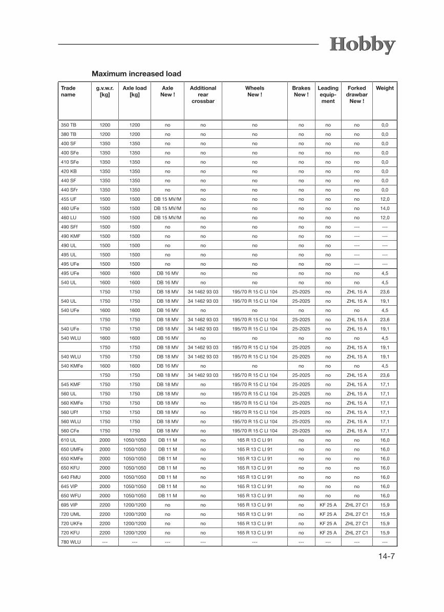
14-7
Maximum increased load
Tradename
g.v.w.r.[kg]
Axle load[kg]
AxleNew !
Additional rear
crossbar
Wheels New !
Brakes New !
Leadingequip-ment
Forked drawbar
New !
Weight
350 TB 1200 1200 no no no no no no 0,0
380 TB 1200 1200 no no no no no no 0,0
400 SF 1350 1350 no no no no no no 0,0
400 SFe 1350 1350 no no no no no no 0,0
410 SFe 1350 1350 no no no no no no 0,0
420 KB 1350 1350 no no no no no no 0,0
440 SF 1350 1350 no no no no no no 0,0
440 SFr 1350 1350 no no no no no no 0,0
455 UF 1500 1500 DB 15 MV/M no no no no no 12,0
460 UFe 1500 1500 DB 15 MV/M no no no no no 14,0
460 LU 1500 1500 DB 15 MV/M no no no no no 12,0
490 SFf 1500 1500 no no no no no --- ---
490 KMF 1500 1500 no no no no no --- ---
490 UL 1500 1500 no no no no no --- ---
495 UL 1500 1500 no no no no no --- ---
495 UFe 1500 1500 no no no no no --- ---
495 UFe 1600 1600 DB 16 MV no no no no no 4,5
540 UL 1600 1600 DB 16 MV no no no no no 4,5
1750 1750 DB 18 MV 34 1462 93 03 195/70 R 15 C LI 104 25-2025 no ZHL 15 A 23,6
540 UL 1750 1750 DB 18 MV 34 1462 93 03 195/70 R 15 C LI 104 25-2025 no ZHL 15 A 19,1
540 UFe 1600 1600 DB 16 MV no no no no no 4,5
1750 1750 DB 18 MV 34 1462 93 03 195/70 R 15 C LI 104 25-2025 no ZHL 15 A 23,6
540 UFe 1750 1750 DB 18 MV 34 1462 93 03 195/70 R 15 C LI 104 25-2025 no ZHL 15 A 19,1
540 WLU 1600 1600 DB 16 MV no no no no no 4,5
1750 1750 DB 18 MV 34 1462 93 03 195/70 R 15 C LI 104 25-2025 no ZHL 15 A 19,1
540 WLU 1750 1750 DB 18 MV 34 1462 93 03 195/70 R 15 C LI 104 25-2025 no ZHL 15 A 19,1
540 KMFe 1600 1600 DB 16 MV no no no no no 4,5
1750 1750 DB 18 MV 34 1462 93 03 195/70 R 15 C LI 104 25-2025 no ZHL 15 A 23,6
545 KMF 1750 1750 DB 18 MV no 195/70 R 15 C LI 104 25-2025 no ZHL 15 A 17,1
560 UL 1750 1750 DB 18 MV no 195/70 R 15 C LI 104 25-2025 no ZHL 15 A 17,1
560 KMFe 1750 1750 DB 18 MV no 195/70 R 15 C LI 104 25-2025 no ZHL 15 A 17,1
560 UFf 1750 1750 DB 18 MV no 195/70 R 15 C LI 104 25-2025 no ZHL 15 A 17,1
560 WLU 1750 1750 DB 18 MV no 195/70 R 15 C LI 104 25-2025 no ZHL 15 A 17,1
560 CFe 1750 1750 DB 18 MV no 195/70 R 15 C LI 104 25-2025 no ZHL 15 A 17,1
610 UL 2000 1050/1050 DB 11 M no 165 R 13 C LI 91 no no no 16,0
650 UMFe 2000 1050/1050 DB 11 M no 165 R 13 C LI 91 no no no 16,0
650 KMFe 2000 1050/1050 DB 11 M no 165 R 13 C LI 91 no no no 16,0
650 KFU 2000 1050/1050 DB 11 M no 165 R 13 C LI 91 no no no 16,0
640 FMU 2000 1050/1050 DB 11 M no 165 R 13 C LI 91 no no no 16,0
645 VIP 2000 1050/1050 DB 11 M no 165 R 13 C LI 91 no no no 16,0
650 WFU 2000 1050/1050 DB 11 M no 165 R 13 C LI 91 no no no 16,0
695 VIP 2200 1200/1200 no no 165 R 13 C LI 91 no KF 25 A ZHL 27 C1 15,9
720 UML 2200 1200/1200 no no 165 R 13 C LI 91 no KF 25 A ZHL 27 C1 15,9
720 UKFe 2200 1200/1200 no no 165 R 13 C LI 91 no KF 25 A ZHL 27 C1 15,9
720 KFU 2200 1200/1200 no no 165 R 13 C LI 91 no KF 25 A ZHL 27 C1 15,9
780 WLU --- --- --- --- --- --- --- --- ---

14-8
14.6 Tires and Rims
Trade name
Tech-nical name
De
Luxe
Exc
elle
nt
La V
ita
bio
nda
La V
ita
vene
to
Pre
stig
e
Technically permitted gross ve-
hicle weight [kg]
Axle load [kg]
Metal wheel
rim
Tire size Air pressure
(bar)
Light alloy rim, size
Light alloy rim,
marking
Tire size Air pres-sure (bar)
350 TB 30 B • 1100 1100 5½ x 14 195/70 R 14 XL LI 96 3,2 6 x 14 OJ14/5 195/70 R 14 XL LI 96 3,2
380 TB 30 M • 1100 1100 5½ x 14 195/70 R 14 XL LI 96 3,2 6 x 14 OJ14/5 195/70 R 14 XL LI 96 3,2
400 SF 30 A • • 1200 1200 5½ x 14 195/70 R 14 XL LI 96 3,2 6 x 14 OJ14/5 195/70 R 14 XL LI 96 3,2
• 1200 1200 Light alloy rims are part of the standard equipment. 6 x 14 OJ14/5 195/70 R 14 XL LI 96 3,2
400 SFe 30 S • 1200 1200 5½ x 14 195/70 R 14 XL LI 96 3,2 6 x 14 OJ14/5 195/70 R 14 XL LI 96 3,2
410 SFe 30 G • 1200 1200 5½ x 14 195/70 R 14 XL LI 96 3,2 6 x 14 OJ14/5 195/70 R 14 XL LI 96 3,2
420 KB 30 T • 1200 1200 5½ x 14 195/70 R 14 XL LI 96 3,2 6 x 14 OJ14/5 195/70 R 14 XL LI 96 3,2
440 SF 30 F • 1200 1200 5½ x 14 195/70 R 14 XL LI 96 3,2 6 x 14 OJ14/5 195/70 R 14 XL LI 96 3,2
440 SFr 30 F • 1200 1200 5½ x 14 195/70 R 14 XL LI 96 3,2 6 x 14 OJ14/5 195/70 R 14 XL LI 96 3,2
455 UF 30 N • 1350 1350 5½ x 14 185 R 14 C LI 102 4,5 6 x 14 OJ14/5 185 R 14 C LI 102 4,5
460 UFe 30 C • • • 1350 1350 5½ x 14 185 R 14 C LI 102 4,5 6 x 14 OJ14/5 185 R 14 C LI 102 4,5
• 1350 1350 Light alloy rims are part of the standard equipment. 6 x 14 OJ14/5 185 R 14 C LI 102 4,5
460 LU 30 J • 1350 1350 5½ x 14 185 R 14 C LI 102 4,5 6 x 14 OJ14/5 185 R 14 C LI 102 4,5
490 SFf 30 H • 1400 1400 5½ x 14 185 R 14 C LI 102 4,5 6 x 14 OJ14/5 185 R 14 C LI 102 4,5
490 KMF 30 U • • 1400 1400 5½ x 14 185 R 14 C LI 102 4,5 6 x 14 OJ14/5 185 R 14 C LI 102 4,5
490 UL 30 R • 1400 1400 5½ x 14 185 R 14 C LI 102 4,5 6 x 14 OJ14/5 185 R 14 C LI 102 4,5
495 UL 30 D • • 1400 1400 5½ x 14 185 R 14 C LI 102 4,5 6 x 14 OJ14/5 185 R 14 C LI 102 4,5
• 1400 1400 Light alloy rims are part of the standard equipment. 6 x 14 OJ14/5 185 R 14 C LI 102 4,5
495 UFe 30 E • 1400 1400 5½ x 14 185 R 14 C LI 102 4,5 6 x 14 OJ14/5 185 R 14 C LI 102 4,5
495 UFe 24 F • 1500 1500 5½ x 14 185 R 14 C LI 102 4,5 6 x 14 OJ14/5 185 R 14 C LI 102 4,5
540 UL 24 M • 1500 1500 5½ x 14 185 R 14 C LI 102 4,5 6 x 14 OJ14/5 185 R 14 C LI 102 4,5
24 M •
540 UL 24 M • 1600 1600 5½ x 14 185 R 14 C LI 102 4,5 6 x 14 OJ14/5 185 R 14 C LI 102 4,5
540 UFe 24 E • 1500 1500 5½ x 14 185 R 14 C LI 102 4,5 6 x 14 OJ14/5 185 R 14 C LI 102 4,5
24 E •
540 UFe 24 W • 1600 1600 5½ x 14 185 R 14 C LI 102 4,5 6 x 14 OJ14/5 185 R 14 C LI 102 4,5
540 WLU 24 J • 1500 1500 5½ x 14 185 R 14 C LI 102 4,5 6 x 14 OJ14/5 185 R 14 C LI 102 4,5
540 WLU 24 J • 1600 1600 5½ x 14 185 R 14 C LI 102 4,5 6 x 14 OJ14/5 185 R 14 C LI 102 4,5
540 KMFe 24 P • 1500 1500 5½ x 14 185 R 14 C LI 102 4,5 6 x 14 OJ14/5 185 R 14 C LI 102 4,5
24 P •
545 KMF 24 R • • • 1600 1600 5½ x 14 185 R 14 C LI 102 4,5 6 x 14 OJ14/5 185 R 14 C LI 102 4,5
• 1600 1600 Light alloy rims are part of the standard equipment. 6 x 14 OJ14/5 185 R 14 C LI 102 4,5
560 UL 24 B • • 1600 1600 5½ x 14 185 R 14 C LI 102 4,5 6 x 14 OJ14/5 185 R 14 C LI 102 4,5
560 KMFe 24 C • 1600 1600 5½ x 14 185 R 14 C LI 102 4,5 6 x 14 OJ14/5 185 R 14 C LI 102 4,5
560 UFf 24 D • 1600 1600 5½ x 14 185 R 14 C LI 102 4,5 6 x 14 OJ14/5 185 R 14 C LI 102 4,5
560 WLU 24 H • • 1600 1600 5½ x 14 185 R 14 C LI 102 4,5 6 x 14 OJ14/5 185 R 14 C LI 102 4,5
560 CFe 24 T • 1600 1600 5½ x 14 185 R 14 C LI 102 4,5 6 x 14 OJ14/5 185 R 14 C LI 102 4,5
610 UL 27 A • 1900 1000/1000 4½ x 13 155/80 R 13 XL LI 84 3,3 5 x 13 TR1 503 155/80 R 13 XL LI 84 3,3
650 UMFe 27 B • 1900 1000/1000 4½ x 13 155/80 R 13 XL LI 84 3,3 5 x 13 TR1 503 155/80 R 13 XL LI 84 3,3
650 KMFe 27 B • • 1900 1000/1000 4½ x 13 155/80 R 13 XL LI 84 3,3 5 x 13 TR1 503 155/80 R 13 XL LI 84 3,3
650 KFU 27 C • 1900 1000/1000 4½ x 13 155/80 R 13 XL LI 84 3,3 5 x 13 TR1 503 155/80 R 13 XL LI 84 3,3
640 FMU 27 K • 1900 1000/1000 Light alloy rims are part of the standard equipment. 5 x 13 OJ13/4 155/80 R 13 XL LI 84 3,3
645 VIP 27 N • 1900 1000/1000 Light alloy rims are part of the standard equipment. 5 x 13 OJ13/4 155/80 R 13 XL LI 84 3,3
650 WFU 27 G • 1900 1000/1000 4½ x 13 155/80 R 13 XL LI 84 3,3 5 x 13 TR1 503 155/80 R 13 XL LI 84 3,3
695 VIP 19 K • 2000 1050/1050 LM-Felgen sind Serie 5 x 13 OJ13/4 165 R 13 C LI 91 3,8
720 UML 19 D • 2000 1050/1050 4½ x 13 165 R 13 C LI 91 3,8 5 x 13 TR1 503 165 R 13 C LI 91 3,8
720 UKFe 19 G • 2000 1050/1050 4½ x 13 165 R 13 C LI 91 3,8 5 x 13 TR1 503 165 R 13 C LI 91 3,8
780 WLU 19 J • 2200 1200/1200 Light alloy rims are part of the standard equipment. 5 x 13 OJ13/4 165 R 13 C LI 91 3,8
Standard version
Metal wheel rims for the standard version
Light alloy rims for the standard version
Metal wheel rim: tightening torque 110 Nm Light alloy rim: tightening torque 120 Nm

14-9
Trade name
Technically permitted gross ve-
hicle weight [kg]
Axle load [kg]
Metal wheel rim
Tire size Air pre-
ssure (bar)
Light alloy rim, size
Light alloy rim,
marking
Tire size Air pres-sure (bar)
350 TB 1200 1200 5½ x 14 195/70 R 14 XL LI 96 3,2 6 x 14 OJ14/5 195/70 R 14 XL LI 96 3,2
380 TB 1200 1200 5½ x 14 195/70 R 14 XL LI 96 3,2 6 x 14 OJ14/5 195/70 R 14 XL LI 96 3,2
400 SF 1350 1350 5½ x 14 195/70 R 14 XL LI 96 3,2 6 x 14 OJ14/5 195/70 R 14 XL LI 96 3,2
1350 1350 Light alloy rims are part of the standard equipment. 6 x 14 OJ14/5 195/70 R 14 XL LI 96 3,2
400 SFe 1350 1350 5½ x 14 195/70 R 14 XL LI 96 3,2 6 x 14 OJ14/5 195/70 R 14 XL LI 96 3,2
410 SFe 1350 1350 5½ x 14 195/70 R 14 XL LI 96 3,2 6 x 14 OJ14/5 195/70 R 14 XL LI 96 3,2
420 KB 1350 1350 5½ x 14 195/70 R 14 XL LI 96 3,2 6 x 14 OJ14/5 195/70 R 14 XL LI 96 3,2
440 SF 1350 1350 5½ x 14 195/70 R 14 XL LI 96 3,2 6 x 14 OJ14/5 195/70 R 14 XL LI 96 3,2
440 SFr 1350 1350 5½ x 14 195/70 R 14 XL LI 96 3,2 6 x 14 OJ14/5 195/70 R 14 XL LI 96 3,2
455 UF 1500 1500 5½ x 14 185 R 14 C LI 102 4,5 6 x 14 OJ14/5 185 R 14 C LI 102 4,5
460 UFe 1500 1500 5½ x 14 185 R 14 C LI 102 4,5 6 x 14 OJ14/5 185 R 14 C LI 102 4,5
1500 1500 Light alloy rims are part of the standard equipment. 6 x 14 OJ14/5 185 R 14 C LI 102 4,5
460 LU 1500 1500 5½ x 14 185 R 14 C LI 102 4,5 6 x 14 OJ14/5 185 R 14 C LI 102 4,5
490 SFf 1500 1500 5½ x 14 185 R 14 C LI 102 4,5 6 x 14 OJ14/5 185 R 14 C LI 102 4,5
490 KMF 1500 1500 5½ x 14 185 R 14 C LI 102 4,5 6 x 14 OJ14/5 185 R 14 C LI 102 4,5
490 UL 1500 1500 5½ x 14 185 R 14 C LI 102 4,5 6 x 14 OJ14/5 185 R 14 C LI 102 4,5
495 UL 1500 1500 5½ x 14 185 R 14 C LI 102 4,5 6 x 14 OJ14/5 185 R 14 C LI 102 4,5
1500 1500 Light alloy rims are part of the standard equipment. 6 x 14 OJ14/5 185 R 14 C LI 102 4,5
495 UFe 1500 1500 5½ x 14 185 R 14 C LI 102 4,5 6 x 14 OJ14/5 185 R 14 C LI 102 4,5
495 UFe 1600 1600 5½ x 14 185 R 14 C LI 102 4,5 6 x 14 OJ14/5 185 R 14 C LI 102 4,5
540 UL 1600 1600 5½ x 14 185 R 14 C LI 102 4,5 6 x 14 OJ14/5 185 R 14 C LI 102 4,5
1750 1750 6 x 15 195/70 R 15 C LI 104 4,5 6 x 15 OJ15/5 195/70 R 15 C LI 104 4,5
540 UL 1750 1750 6 x 15 195/70 R 15 C LI 104 4,5 6 x 15 OJ15/5 195/70 R 15 C LI 104 4,5
540 UFe 1600 1600 5½ x 14 185 R 14 C LI 102 4,5 6 x 14 OJ14/5 185 R 14 C LI 102 4,5
1750 1750 6 x 15 195/70 R 15 C LI 104 4,5 6 x 15 OJ15/5 195/70 R 15 C LI 104 4,5
540 UFe 1750 1750 6 x 15 195/70 R 15 C LI 104 4,5 6 x 15 OJ15/5 195/70 R 15 C LI 104 4,5
540 WLU 1600 1600 5½ x 14 185 R 14 C LI 102 4,5 6 x 14 OJ14/5 185 R 14 C LI 102 4,5
1750 1750 6 x 15 195/70 R 15 C LI 104 4,5 6 x 15 OJ15/5 195/70 R 15 C LI 104 4,5
540 WLU 1750 1750 6 x 15 195/70 R 15 C LI 104 4,5 6 x 15 OJ15/5 195/70 R 15 C LI 104 4,5
540 KMFe 1600 1600 5½ x 14 185 R 14 C LI 102 4,5 6 x 14 OJ14/5 185 R 14 C LI 102 4,5
1750 1750 6 x 15 195/70 R 15 C LI 104 4,5 6 x 15 OJ15/5 195/70 R 15 C LI 104 4,5
545 KMF 1750 1750 6 x 15 195/70 R 15 C LI 104 4,5 6 x 15 OJ15/5 195/70 R 15 C LI 104 4,5
1750 1750 Light alloy rims are part of the standard equipment. 6 x 15 OJ15/5 195/70 R 15 C LI 104 4,5
560 UL 1750 1750 6 x 15 195/70 R 15 C LI 104 4,5 6 x 15 OJ15/5 195/70 R 15 C LI 104 4,5
560 KMFe 1750 1750 6 x 15 195/70 R 15 C LI 104 4,5 6 x 15 OJ15/5 195/70 R 15 C LI 104 4,5
560 UFf 1750 1750 6 x 15 195/70 R 15 C LI 104 4,5 6 x 15 OJ15/5 195/70 R 15 C LI 104 4,5
560 WLU 1750 1750 6 x 15 195/70 R 15 C LI 104 4,5 6 x 15 OJ15/5 195/70 R 15 C LI 104 4,5
560 CFe 1750 1750 6 x 15 195/70 R 15 C LI 104 4,5 6 x 15 OJ15/5 195/70 R 15 C LI 104 4,5
610 UL 2000 1050/1050 4½ x 13 165 R 13 C LI 91 3,8 5 x 13 TR1 503 165 R 13 C LI 91 3,8
650 UMFe 2000 1050/1050 4½ x 13 165 R 13 C LI 91 3,8 5 x 13 TR1 503 165 R 13 C LI 91 3,8
650 KMFe 2000 1050/1050 4½ x 13 165 R 13 C LI 91 3,8 5 x 13 TR1 503 165 R 13 C LI 91 3,8
650 KFU 2000 1050/1050 4½ x 13 165 R 13 C LI 91 3,8 5 x 13 TR1 503 165 R 13 C LI 91 3,8
640 FMU 2000 1050/1050 Light alloy rims are part of the standard equipment. 5 x 13 OJ13/4 165 R 13 C LI 91 3,8
645 VIP 2000 1050/1050 Light alloy rims are part of the standard equipment. 5 x 13 OJ13/4 165 R 13 C LI 91 3,8
650 WFU 2000 1050/1050 4½ x 13 165 R 13 C LI 91 3,8 5 x 13 TR1 503 165 R 13 C LI 91 3,8
695 VIP 2200 1200/1200 Light alloy rims are part of the standard equipment. 5 x 13 OJ13/4 165 R 13 C LI 91 3,8
720 UML 2200 1200/1200 4½ x 13 165 R 13 C LI 91 3,8 5 x 13 TR1 503 165 R 13 C LI 91 3,8
720 UKFe 2200 1200/1200 4½ x 13 165 R 13 C LI 91 3,8 5 x 13 TR1 503 165 R 13 C LI 91 3,8
780 WLU --- --- --- --- --- --- ---
Max. increase (for increased load)
Metal wheel rims for increased load
Light alloy rims for increased load
Tire bolts: retainer for all 13" + 14" metal wheel rims and all light alloy rims (incl. 15"): cone washer retainer for all 15" metal wheel rims: SPHERICAL WHEEL BOLT

14-10
14.7 Lighting
12V Vehicle lighting
Position Description Voltage Watt
exterior Left blinker 12 21
exterior Right blinker 12 21
exterior Parking light 12 5
exterior Brake light 12 21
exterior Rear light 12
exterior Licence plate illumination 12 5
exterior Clearance lights 12 3
exterior Running light 12 3
exterior Side marker light 12 LED
exterior Third brake light 12 LED
exterior Back-up light 12
exterior Fog tail lamp 12
12V Interior lighting
Lamp Lighting
Ceiling lamp, round, grey 3 x 5 W + 3 x 10 W
Halogen ceiling lamp 3 x 10 W
Closet lamp LED
Children`s bed lamp 3 x 5 W
Halogen Washroom lamp 3 x 10 W
Washroom lamp LED LED 9fach G4 1 W
Corner lamp 2 x 10 W
Kitchenlamp silver 12V 4 x 10 W
Kitchenlamp silver 230/12V 5 x 5 W
Built-in spotlight 1980/12H/G/chrom 1 x 10 W
Built-in spotlight silber 1 x 5 W
Spotlight 1 x 10 W
Wall lamp 1 x 10 W
LED recessed spotlight 1 x 0,2 W
Entry lamp 2 x 5 W
Partition light LED strips 1 W
LED recessed spotlight LED 9 ports G4 1 W

14-11
14.8 MouldingLi
ning
wit
h a
pre
ssur
e-re
sist
ant
pla
stic
ho
neyc
om
b d
esig
n
Mo
uld
ing
30
mm
wid
e
Blo
ck 6
0x30
mm
Blo
ck 6
0x30
mm
Blo
ck 6
0x30
mm
Blo
ck 6
0x30
mm

14-12

Ix-1
IndexAAccessories 11-1Additional equipment 03-12Additional loads 03-12Air-circulation fan 10-4Airing 12-6Auxiliary battery 07-13
BBasic equipment 03-12,14-3Bed conversion 06-7Bicycle carrier 05-9Boiler 10-13Brakes 02-7, 12-4
CCEE plug 07-11Changing the tire 04-4Chassis 12-8Checking the gas system 09-1Children‘s beds 06-9Choosing a parking space 02-8Circuit diagram, external 07-16Cleaning the exterior 12-6Cleaning the interior 12-9Clothes cupboard light 07-12Control panel 07-2Cooker 10-18
DDefinition of masses 03-11Doors opening and closing 06-1 upkeep 12-8Doors and flaps interior 06-1Drawbar load 02-5Drawbars 03-6Drawers 06-2Drawgear 12-2Driving 02-6Driving in curves 02-6Driving in reverse 02-7Driving noises 12-3
EElectric auxiliary heating 10-5Electric floor heating 10-6Electric power supply 07-11Electrical devices redirecting 02-8
Electrical system 07-14Elevating table 06-5Emergency equipment 02-1Entry door 05-3 door, upper part 05-4 interior 05-3Environmental protection 13-1
FFighting a fire 02-2First aid kit 02-1Flaps opening and closing 06-1Flush toilet 08-6Forced ventilation 05-1Fresh water tank, built-in 08-2Fume hood 10-20Fuses, assignment of 07-8
GGas 09-1Gas bottle container 09-3Gas container flap 05-6Gas cooker 10-18 operating the cooker 10-19Gas supply 09-3Gas system inspection 09-1General inspection 03-9Greasing 12-1Guide rail for outer tent 05-7Guide rail for skirting 05-7
HHand brake 03-6Heating 05-2, 09-4High-visibility vest 02-1Hitching/unhitching 03-3Hot-air heating10-2Hot-water heating system 10-7Hot water supply 08-4Indirect lighting 07-11
IInsect screen 06-10, 06-11
LLamps changing the rear light bulbs 12-5Light control system 07-17Lighting 07-18, 14-10

Ix-2
Loading 02-4
MMaintenance 12-1Mass, definition 03-11Media oval 06-3Media shelf, extendable 06-4Microwave 10-22Moulding 14-11Mover 03-6
OOiling 03-1, 1 2-1Outer tent light 07-13Oven 10-20Overrunning brake facility 03-7
PPillared table 06-6Plissés 06-10Porta Potti 08-6Profile depth 04-2Push lock 06-2
RRear light bulbs 12-5Refrigerator 05-1, 10-15Registration 03-9Regulator knobs 09-1Remote control 07-7Remote control 1 07-3Remote control 2 07-3Rims 04-3Roof 05-7Roof bonnet 06-12Roof fan 06-11Roof load 05-7Rotating stanchions 03-8
SSafety tips 07-1Securing the vehicle 02-8Self-sufficient package 07-13Service flaps 05-5Shunting 02-7Shutoff valves place of installation 09-4Step tread 05-5Suitability for a speed of 100 km/h 03-10Swivelling table 06-6
TTables 06-5Tanks 08-2Technical data basic equipment 14-3 possibilities for increasing loads 14-6 technical data 14-4 tires and rims 14-8 tire pressure 14-1 weights 14-1Technically permissible maximum weight 03-12Therme 08-4Tire pressure 04-1,14-1Tire repair kit 04-6Tires 04-1Tires, age of 04-2Toilet 08-6Toilet flap 05-6
UUltraheat 10-5Undercarriage 12-8Upkeep 12-6
VValves 09-1Vehicle keys 02-1Ventilation and de-aerating 05-1VIN (Vehicle Identification No.) 03-10Warning triangle 02-1
WWaste water tank 08-2Water supply 08-1Water system 02-9Windows hinged windows 06-9 upkeep 12-8Winter operation 12-13