operation and maintenance manual - · pdf fileisolation transformer requirements torque and...
TRANSCRIPT

OPERATION and MAINTENANCEMANUAL
for
MODEL PV-20208
20 KW Grid-TiedPhotovoltaic Inverter
Document #151119Revision B November 10, 2000
IMPORTANT SAFETY INSTRUCTIONSSAVE THESE INSTRUCTIONS - THIS MANUAL CONTAINS IMPORTANT INSTRUC-TIONS FOR TRACE TECHNOLOGIES MODEL PV-20208 GRID TIED PHOTOVOLTAICINVERTER THAT SHALL BE FOLLOWED DURING INSTALLATION AND MAINTENANCEOF THE PV-20208.
Xantrex Technologies Inc./Trace Technologies Corp.161-G SOUTH VASCO ROAD
Livermore, CA 94550(925) 245-5400
Copyright 2000, Xantrex Technologies Inc./Trace Technologies Corp.

Table of Contents
Section 1: Product DescriptionIntroductionMajor ComponentsInterconnection Standards ComplianceSpecificationsEquipment Symbol
Section 2: SafetySafety FeaturesIsolation ProcedureAnti Island Protection
Section 3: Installation And Initial Turn-OnIsolation Transformer RequirementsTorque and Wire Gauge SpecificationsInstallation InstructionsInterconnection WiringInitial Turn On Procedure
Section 4: OperationDescription of System OperationOperator Interface Panel (LED and LCD)Example of Normal System Operation
Section 5: TroubleshootingGeneralFault Conditions and TroubleshootingFault ClearingFault Descriptons and Troubleshooting
Section 6: Preventative MaintenanceIsolation ProcedureTurn-On Procedure
Section 7: Drawings and Major Parts ListsSystem Schematic, Grid Tied PV Inverter, PV-SeriesAssembly Drawings And Major Parts ListsEnvelope Drawing, Grid Tied PV Inverter, PV-20208UL Listing Document, April 25, 2000UL Listing Card, September 8, 2000Accessories

SECTION 1PRODUCT DESCRIPTION
PV-20208 Photovoltaic InverterOperation and Maintenance Manual
Copyright 2000, Xantrex Technologies Inc./Trace Technologies Corp.
DOCUMENT: 1511191-1
INTRODUCTION
The Trace Technologies Model PV-20208 is a 20KW Grid Tied Photovoltaic Inverter. It utilizes ad-vanced power electronics to allow interface of a photovoltaic array with a utility grid. The PV-20208 isa highly integrated assembly, consisting of an inverter bridge and associated control electronics all ona single board. The PV-20208 control software provides for complete overall system control with avariety of protective and safety features.
MAJOR COMPONENTS
The major components of the PV-20208 are identified in Drawing No. 151121.
Main EnclosureThe enclosure (shown in Figure 1-1) is NEMA-4 rated. The PV-20208 enclosure contains the Inte-grated Bus Board, output line filter (insuring that the PV-20208 line currents and voltages meet IEEE-519 harmonic distortion requirements), control power transformers, and A/C contactor (PV-20208 A/C output to the grid). Also found within the enclosure are the system protection devices (control powercircuit fuses). The front door of the enclosure contains the operator interface panel (three LED’s orLCD and an on/off switch).
Figure 1-1 Figure 1-2
SECTION 1PRODUCT DESCRIPTION
PV-20208 Photovoltaic InverterOperation and Maintenance Manual
Copyright 2000, Xantrex Technologies Inc./Trace Technologies Corp.
DOCUMENT: 1511191-2
Integrated Bus BoardThe PV-20208 design makes use of a fully integrated bus board as shown in Figure 1-2. The bus boardassembly is mounted to an aluminum extrusion heat sink, which mounts through an opening in theback of the enclosure. The power electronics is comprised of a six pack of IGBT devices, mounted tothe heat sink. The bus board is mounted on top of the IGBT six pack device, and is supported througha series of standoffs attached to the heat sink.
The bus board contains all of the necessary control functions to drive the (attached) switching transis-tors. The bus board contains the following functional circuits: D/C control power supplies (+5V, +/-15V and four isolated +15V sources for the IGBT’s), A/C and D/C high voltage measurement, A/C andground current measurements, contactor and indicator controls, discrete input sensing (on/off switch),and closed loop PWM modulators. The bus board contains a micro-controller chip to perform the low-level control functions associated with the collection of measurement and driving the pulse widthmodulators.
A plug in DSP module controls the bus board. The DSP module is designed to the industry standard,PC-104 specification, and is used to perform the majority of the calculations needed to control the busboard. The most significant tasks are: control of PV-20208 electromechanical components and powerelectronics converters, signal conditioning (digital filtering and transformations), and communicationwith the operator interface panel and system sensors.
The PV array ties directly to the DC bus. The inverter controller manages the transfer of power betweenthe DC bus and the utility grid.
INTERCONNECTION STANDARDS COMPLIANCE
The PV-20208 has been tested and certified by Underwriters Laboratories to be in compliance withUL1741 Static Inverters And Charge Controllers For Use In Photovoltaic Power Systems, as wellas IEEE-P929 Recommended Practice For Utility Interface Of Photovoltaic (PV) Systems.
IEEE-P929 provides guidance regarding equipment and functions necessary to ensure compatible op-eration of photovoltaic systems which are connected in parallel with the electric utility. UL1741 is thetest procedure performed by Underwriters Laboratory on the PV-20208 to verify it meets the recom-mendations of IEEE-P929. Refer to both documents for details of these recommendations and testprocedures.
CAUTIONThe fuses within the PV-20208 are intended for protecting the PV-20208 control cir-cuitry only. They are not intended to provide protection for the PV array or externalcabling.

SECTION 1PRODUCT DESCRIPTION
PV-20208 Photovoltaic InverterOperation and Maintenance Manual
Copyright 2000, Xantrex Technologies Inc./Trace Technologies Corp.
DOCUMENT: 1511191-3
egatloVeniLCAlanimoN %01±,CAV802
tnerruCeniLCAmumixaM )egatlovenilwolta(SMRA86.16
ycneuqerFeniLlanimoN zH5.0±,zH06
daoLCAsuounitnoC [email protected]
egnaRegatloVVP CDV006-033
tnerruCmumixaMVP CDA8.36
noitarugifnoCVPralop-ibro,dednuorgevitagenraloponoM
dnuorglartuen
erutarepmeTgnitarepO* C°05ot02-
erutarepmeTegarotS C°05ot04-
gnitaRerutarepmeTtneibmAmumixaM C°05
ytidimuHevitaleR gnisnednoc-noN,%59oT
noitavelE teef006,6evobadetareD
)sehcnini(snoisnemiD 41X52X03
thgieW .sbl571.xorppA
epyTerusolcnE 4AMEN
eliFgnitsiLLU 653991E-eliF
EQUIPMENT SYMBOL
Chassis ground – Customer supplied system ground connection point. This symbol may be found neara stud within the main enclosure. It is provided as a location to bond the electrical system equipmentground.
*If ambient temperature is between -20 to 0° C, the unit must be powered up in standby for at leastone hour prior to going on-line.
SPECIFICATIONS
The PV-20208 has been designed for photovoltaic power systems, which operate within the followingspecifications. Application of the PV-20208 in a manner inconsistent with these specifications maycause damage to the PV-20208 and other system components, and is a violation of the terms of thewarranty.

DOCUMENT: 151119
SECTION 2SAFETY
PV-20208 Photovoltaic InverterOperation and Maintenance Manual
Copyright 2000, Xantrex Technologies Inc./Trace Technologies Corp.
2-1
SAFETY FEATURES
Front Panel IndicatorsThe PV-20208 incorporates three colored LED indicators, used to show the current operating state ofthe inverter. The indicators have the following meanings:• Red: Fault Mode - The inverter has sensed an abnormal condition. To reset the unit (clearing the
fault condition), cycle the on/off switch (see below).• Amber: Sleep Mode – The inverter is waiting for sufficient PV voltage to start the inverter.• Green: Operator Mode - The inverter is active and generating A/C current.
On/Off SwitchThe PV-20208 incorporates a maintained position on/off switch located on the front door of the enclo-sure. Under normal conditions, the on/off switch in the on position. Turning the switch to the offposition will initiate a controlled shutdown of the PV-20208 and open the main contactor within theunit. The PV-20208 is prevented from being restarted until the on/off switch is turned back to the onposition. Cycling the on/off switch will reset the PV-20208 and attempt to clear any system fault.
Main Enclosure DoorThe front door of the PV-20208 main enclosure is pad lockable. It is recommended that the PV-20208enclosure door be padlocked during normal operation.
Fault ReportingAny fault conditions are reported to the operator interface. If the PV-20208 is equipped with LED’s,the red LED will light and the green LED will flash the corresponding number of the fault. If the PV-20208 is equipped with the LCD option, the LCD will display a text description of the fault. Refer toSection 5, Troubleshooting, for detailed descriptions of system fault conditions.
PV Ground Fault DetectionThe PV-20208 is equipped with ground fault detection circuitry and control. The single point of PV
The PV-20208 enclosure contains exposed high voltage conductors. The enclosuredoor should remain closed, except during maintenance or testing. These servicinginstructions are for use by qualified personnel only. To reduce the risk of electricshock, do not perform any servicing other than that specified in the operatinginstructions unless you are qualified to do so. Do not open the cabinet door ifextreme moisture is present (rain or heavy dew).
WARNING
The PV-20208 does not incorporate a door interlock switch. Please make sure theunit is powered down, and isolated from the utility grid and PV panels, prior toopening the enclosure door. (Allow 5 minutes for any stored potentials to be dis-charged, prior to opening the unit). The front door of the PV-20208 main enclosureis pad lockable. It is recommended that the PV-20208 enclosure door be padlockedduring normal operation.
WARNING

DOCUMENT: 151119
SECTION 2SAFETY
PV-20208 Photovoltaic InverterOperation and Maintenance Manual
Copyright 2000, Xantrex Technologies Inc./Trace Technologies Corp.
2-2
The terminals of the PV input may be energized if the arrays are energized. Inaddition, allow 5 minutes for all capacitors within the enclosure to discharge afterdisconnecting the PV-20208 from AC and DC sources.
WARNING
ISOLATION PROCEDURE
The following procedure should be followed to de-energize the PV-20208 for maintenance:
ANTI ISLAND PROTECTION
A digital phase-shift-loop (PSL) circuit is implemented in the DSP inverter controller to prevent“Islanding” of the PV-20208.
The DSP continuously makes minor adjustments to the power factor phase angle above and belowunity. In the event of a utility outage, these adjustments destabilize the feedback between the inverterand the remaining load, resulting in an over/under frequency or voltage condition. The PV-20208then performs an orderly shutdown. The fault condition will remain until the utility voltage andfrequency have returned to normal for 5 minutes.
This method has been extensively tested and proven to exceed the requirements of UL 1741.
system ground must be routed through CT1 on the main control board (see section 3, installa-tion and section 7, system schematic for further detail). Upon detection of 1.5 amps of groundfault current, the PV-20208 executes an orderly shutdown, and annunciates a ground fault at theoperator interface. The PV-20208 will remain faulted until the ground fault is remedied andcleared at the operator interface (see section 5, troubleshooting).
1. Turn the on/off switch to the off position.2. Open the PV array disconnect switch (if present).3. Open the AC interface disconnect (if present).4. Open the isolation transformer circuit breaker.5. Install lockout devices on the isolation transformer circuit breaker and PV disconnect switch (if
present).

SECTION 3INSTALLATION AND INITIAL TURN-ON
PV-20208 Photovoltaic InverterOperation and Maintenance Manual
Copyright 2000, Xantrex Technologies Inc./Trace Technologies Corp.
DOCUMENT: 1511193-1
ISOLATION TRANSFORMER REQUIREMENTS
The PV-20208 is required to have an isolation transformer wired between the inverter AC output andthe utility interconnection. Any standard dry-type isolation transformer is compatible with the PV-20208 as long as the inverter side is rated for a minimum of 20KVA continuous duty.
Inverter Side Isolation Transformer RequirementsThe inverter side transformer windings may be configured either delta or WYE, and must be rated for208 VAC. Trace Technologies recommends using a delta wound transformer to avoid installation mis-takes. If a WYE wound transformer is used to interface with the PV-20208, and the PV array isgrounded, the neutral (X0) must be left floating. If the neutral is tied to ground, the inverter will notfunction properly, and may be damaged.
Utility Side Isolation Transformer RequirementsThe utility side isolation transformer windings may be configured either delta or WYE, and must berated for the utility voltage at the point of utility inter-connection. Check with the utility of jurisdictionwhen selecting an isolation transformer configuration. If a WYE wound transformer is used to interfacewith the utility, it is not necessary to connect the neutral (X0) to ground. The PV-20208 is a balanced,three phase, current sourcing inverter, and only operates with the presence of a stable utility voltage.Single phase grounded loads which may be present between the transformer and utility, will maintaintheir existing ground reference at the utility distribution transformer. Grounding the neutral of a WYEwound transformer may create an “open delta” condition, depending on the utility configuration. Thiscondition may keep the PV-20208 from detecting a loss of phase condition on the utility system,which may allow potentially lethal voltage to be present on the open phase wiring.
Contact your Xantrex/Trace Technologies distributor if you have any questions regarding isolationtransformer requirements.
Check with the local utility of jurisdiction when selecting the winding configura-tion of the isolation transformer. Individual utilities may have unique require-ments related to isolation transformer wiring. Some winding configurations maykeep the PV-20208 from detecting a loss of phase condition on the utility systemwhich may allow potentially lethal voltage to be present on the open phase wir-ings.
WARNING
TORQUE AND WIRE GAUGE SPECIFICATIONS
The following torque specifications are to be used on all electrical interfaces made during installationof the PV-20208.
eziStloBrokcolBlanimreT gnitteSeuqroT
1-6M mN9.5/.sblni25
23126tumwahS/zarreF mN6.31-3.2/sblni021-02
Torque Table

SECTION 3INSTALLATION AND INITIAL TURN-ON
PV-20208 Photovoltaic InverterOperation and Maintenance Manual
Copyright 2000, Xantrex Technologies Inc./Trace Technologies Corp.
DOCUMENT: 1511193-2
All wiring methods shall be in accordance with the National Electrical Code ANSI/NFPA 70. All power conductors interfacing to the PV-20208 should be sized inaccordance with the National Electric Code ANSI/NFPA 70 and local codes. Largegauge wire must have a minimum bend radius dependent upon the wire gauge(refer to the National Electric Code, Article 373-6B). Take care to keep the wirebundles away from any sharp edges which may damage wire insulation over time.Trace Technologies recommends using No. 6 AWG, 105 degrees C, minimum,copper wire for all connections with the PV-20208.
CAUTION
Ventilation Considerations1. Maintain a minimum 6” clearance above and below the PV-20208 for proper cooling fan operation.2. Maintain a minimum 1” clearance to the left and right of the PV-20208.
Installation1. The unit must be mounted at least 3’ off the ground, and 12” above any horizontal surface.2. Screw two 3/8” x 3-1/2” long lag bolts into existing studs in the wall (16-inch mounting center) at
lower mounting level on PV-20208. Lag bolts should be horizontally level with each other. Leavea minimum of 1” of bolt protruding from the wall.
3. Place the PV-20208 bottom mounting ears, shown in Figure 3-1 and Figure 3-2 onto installed lagbolts. (See following page.)
4. Hold the unit against wall and install upper lag bolts (3/8” x 3-1/2”). Tighten bolts firmly.5. Tighten lower lag bolts while unit is held in place.6. Install two 1-1/2” liquid tight connectors (included with the PV-20208) where shown in
Figure 3-3. (See following page.)
INSTALLATION INSTRUCTIONS
noitanimreT GWAegnaReriW
)CA(rotcatnoC 01#-3#
)CD(kcolBnoitubirtsiD 41#-0/2
The following table shows acceptable wire gauges to be connected to the PV-20208 AC and DCinputs.
Wire Gauge Table
Figure 3-1

SECTION 3INSTALLATION AND INITIAL TURN-ON
PV-20208 Photovoltaic InverterOperation and Maintenance Manual
Copyright 2000, Xantrex Technologies Inc./Trace Technologies Corp.
DOCUMENT: 1511193-3
Figure 3-2
Figure 3-3
LIQUID TIGHT CONNECTORS
Array Grounding and Ground Fault DetectionIf grounding the PV array is required for monopolar orbipolar arrays, jumper TB1-2 to a (PV-) cabinet groundstud. If ground fault detection is required, route thisjumper through CT1 located on the lower right handcorner of the control board (see the system schematicfor further detail). This must be the only point of PVgrounding for the PV-20208 and the ground faultdetection system to function properly.
CONTROL BOARD & CT1
CT1The input and output circuits are isolated fromthe enclosure, and that system grounding, if re-quired by sections 690-41 and 690-42 of the Na-tional Electric Code, ANSI/NFPA 70, is theresponsibiliy of the installer.
CAUTION

SECTION 3INSTALLATION AND INITIAL TURN-ON
PV-20208 Photovoltaic InverterOperation and Maintenance Manual
Copyright 2000, Xantrex Technologies Inc./Trace Technologies Corp.
DOCUMENT: 1511193-4
To reduce the risk of fire, connect only to a cir-cuit provided with 90 amperes maximum branchcircuit overcurrent protection in accordance withthe National Electrical Code, ANSI/NFPA 70.
CAUTION
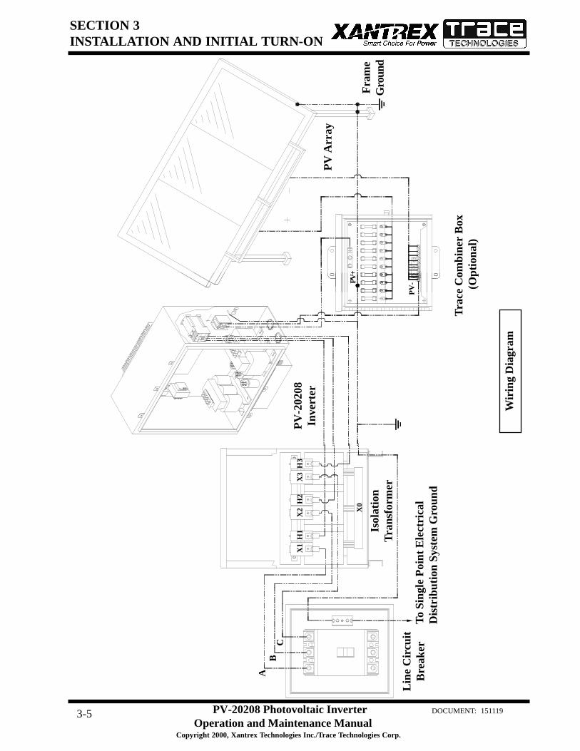
INTERCONNECTION WIRING
The following wires for connecting the PV-20208 to ex-ternal devices are not provided by Xantrex/Trace Tech-nologies: (See wiring diagram on the following page.)
Phase-SequencingThe PV-20208 is equipped with an automatic phase-detection control algorithm. This allows the utilityinterface conductors to be connected in any sequenceconvenient at the time of installation. Upon systeminitialization at power-up, the PV-20208 determinesthe phase sequence of the utility connection andconfigures the modulator drivers accordingly.
• 3-Phase 208 VAC inverter output (main contactor, see picture) to terminals of the 208 VAC deltaside of isolation transformer. If the inverter side of the isolation transformer is configuredWYE and the PV array is grounded, the neutral must be left floating. Ground loops willexist when the inverter starts switching, which will cause the inverter to shut down due tophase over-currents and may result in damage to the PV-20208. Also, insure that thisneutral is not bonded to the isolation transformer frame.
• System ground to the isolation transformer chassis ground.• Isolation transformer grid side terminals to line circuit breaker (or the AC disconnect switch if
present).• PV frame ground to PV-20208 enclosure chassis ground stud.• PV-20208 enclosure chassis ground stud to the electrical distribution system ground.• PV+ to the inverter enclosure terminal block TB1-1.• PV- to the inverter enclosure terminal block TB1-2.
Install all wires listed above. Refer to the system schematics in Section 7 for more detailed terminallocations.
MAIN CONTACTOR
SECTION 3INSTALLATION AND INITIAL TURN-ON
PV-20208 Photovoltaic InverterOperation and Maintenance Manual
Copyright 2000, Xantrex Technologies Inc./Trace Technologies Corp.
DOCUMENT: 1511193-5
Wir
ing
Dia
gram
Fra
me
Gro
und
Lin
e C
ircu
itB
reak
er
Isol
atio
nT
rans
form
er
PV
-202
08In
vert
er
To S
ingl
e P
oint
Ele
ctri
cal
Dis
trib
utio
n Sy
stem
Gro
und
PV
Arr
ay
Tra
ce C
ombi
ner
Box
(O
ptio
nal)
AB
C
X1
H1
X2
H2
X3
H3
X0
PV+
PV
-
SECTION 3INSTALLATION AND INITIAL TURN-ON
PV-20208 Photovoltaic InverterOperation and Maintenance Manual
Copyright 2000, Xantrex Technologies Inc./Trace Technologies Corp.
DOCUMENT: 1511193-6
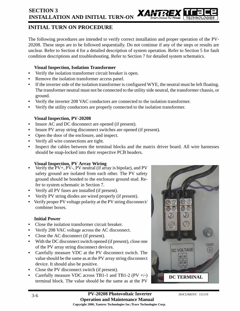
• Verify the PV+, PV-, PV neutral (if array is bipolar), and PVsafety ground are isolated from each other. The PV safetyground should be bonded to the enclosure ground stud. Re-fer to system schematic in Section 7.
• Verify all PV fuses are installed (if present).• Verify PV string diodes are wired properly (if present).• Verify proper PV voltage polarity at the PV string disconnect/
combiner boxes.
Initial Power• Close the isolation transformer circuit breaker.• Verify 208 VAC voltage across the AC disconnect.• Close the AC disconnect (if present).• With the DC disconnect switch opened (if present), close one
of the PV array string disconnect devices.• Carefully measure VDC at the PV disconnect switch. The
value should be the same as at the PV array string disconnectdevice. It should also be positive.
• Close the PV disconnect switch (if present).• Carefully measure VDC across TB1-1 and TB1-2 (PV +/-)
terminal block. The value should be the same as at the PV
INITIAL TURN ON PROCEDURE
The following procedures are intended to verify correct installation and proper operation of the PV-20208. These steps are to be followed sequentially. Do not continue if any of the steps or results areunclear. Refer to Section 4 for a detailed description of system operation. Refer to Section 5 for faultcondition descriptions and troubleshooting. Refer to Section 7 for detailed system schematics.
Visual Inspection, Isolation Transformer• Verify the isolation transformer circuit breaker is open.• Remove the isolation transformer access panel.• If the inverter side of the isolation transformer is configured WYE, the neutral must be left floating.
The transformer neutral must not be connected to the utility side neutral, the transformer chassis, orground.
• Verify the inverter 208 VAC conductors are connected to the isolation transformer.• Verify the utility conductors are properly connected to the isolation transformer.
Visual Inspection, PV-20208• Insure AC and DC disconnect are opened (if present).• Insure PV array string disconnect switches are opened (if present).• Open the door of the enclosure, and inspect.• Verify all wire connections are tight.• Inspect the cables between the terminal blocks and the matrix driver board. All wire harnesses
should be snap-locked into their respective PCB headers.
Visual Inspection, PV Array Wiring
DC TERMINAL

SECTION 3INSTALLATION AND INITIAL TURN-ON
PV-20208 Photovoltaic InverterOperation and Maintenance Manual
Copyright 2000, Xantrex Technologies Inc./Trace Technologies Corp.
DOCUMENT: 1511193-7
array string disconnect device. It should also be positive.• Carefully measure VDC across the matrix + and – busses. The value should be the same as at the
PV array string disconnect switch. It should also be positive.• Open the PV disconnect switch. The matrix capacitor bank voltage should slowly degrade to near
zero over a 5-minute period.• Open all PV string disconnect switches.
System Verification• Ensure the on/off switch is enabled.• Upon applying 208 VAC power to the PV-20208, observe the three LED indicator lights on the
front door. The LED’s should be switching on and off in a sequenced pattern. The LED’s may bedifficult to see depending on external light conditions. After approximately 15 seconds, the panelshould finish initialization
• Remedy any faults reported. If the fault indicator does not change, the fault condition is still present(see Section 5). Cycling the on/off switch will reset the PV-20208 and attempt to clear any systemfaults. Once all faults are cleared, the amber indicator light will come on indicating the PV-20208is in standby.
• Close all PV array string disconnect switches (if present).• Close the main PV disconnect switch (if present).• If the PV voltage is above the PV Start Voltage setpoint, and the PV Start Time is exceeded, the PV-
20208 should transition to “Power Tracking” (see Section 4, Operation).• Depending upon solar conditions, the PV-20208 may not operate at full power. If the PV array is
not experiencing full sun, the PV maximum power tracker will regulate the PV voltage to maintainmaximum PV power output. (See section 4 for further description of the peak power tracker).
• The PV-20208 is now fully operational.
Fine Tuning• All PV-20208 operating parameters have been set at the factory, based upon prior experience with
various PV arrays. Parameters may be modified using an optional graphical user interface. Contactyour Xantrex/Trace Technologies distributor for further information.
• It is recommended that the PV-20208 be watched during Wake-Up and Sleep Test. If the PV-20208cycles between operating and sleeping at either of these times, the operating setpoints may not beset properly. (Refer to Section 4 for a detailed description of PV-20208 operating states). The PV-20208 should not cycle if the setpoints are set properly.

PV-20208 Photovoltaic InverterOperation and Maintenance Manual
Copyright 2000, Xantrex Technologies/Trace Technologies Corp.
DOCUMENT: 1511194-1
SECTION 4OPERATION
DESCRIPTION OF SYSTEM OPERATION
OverviewThe PV-20208 is a fully automated grid-tied photovoltaic inverter. Manual interaction or control of theinverter is necessary only in the event of a system fault. The following conditions govern PV-20208operation:
• Stable utility voltage and frequency must be present for all states of operation.• Fault states are automatic from any state of operation. A fault will cause the PV-20208 to immedi-
ately stop processing all power. The fault condition will be reported to the operator interface.• The on/off switch, located on the front door of the PV-20208, must be switched to the on position
for all operating states.• Cycling the on/off switch attempts to clear any system faults and return the PV-20208 to normal
operation.
Operating StatesControl software governs the operation of the PV-20208. There are five main operating states. Thefollowing descriptions depict the LED interface. Inverters configured with LCD displays will indicateoperating states on the display.
• Standby: The amber LED is illuminated. The PCU monitors the status of the PV array and utilitygrid, waiting until the PV array voltage is sufficient to export power to the utility.
• Wake-Up: The amber LED is illuminated. Once the PV voltage is sufficient to export power to theutility grid, the PV-20208 will wait 5 minutes before starting to insure the voltage is not transient innature. This keeps the system from cycling during unstable irradiance conditions.
• Power Tracking: The green LED will illuminate while the PV-20208 delivers power to the utility.This is the standard operating state of the PV-20208. The PV-20208 maximum power tracker willoptimize power output from the PV array. If available PV power is above the maximum powerrating of the PV-20208, the inverter will current limit, which will cause the PV voltage to riseabove the array peak power voltage. The minimum operating voltage of the PV-20208 is 330 VDC.The power tracker will not track voltage below this point, regardless of the actual peak powervoltage of the PV array.
• Sleep Test: The control system will begin a 5 minute sleep test. This normally indicates the PVirradiance is declining as the sun sets. If the output power remains below 200 watts during the 5minute sleep test, the system will transition to standby. The time delay allows the inverter to ridethrough any temporary irradiance reductions.
• Fault: The PV-20208 has encountered a fault condition. When this happens, regardless of the PV-20208 state-of-operation, the PV-20208 will stop processing all power and execute an orderly sys-tem shutdown. The red LED will illuminate while the yellow and green LED’s flash the fault code(See section 5, Troubleshooting).
On early versions of the PV-20208, a push-pull Emergency Stop switch was usedinstead of the on/off switch. It functioned in the same manner described for the on/off switch.
NOTE
OPERATOR INTERFACE (LED and LCD)

PV-20208 Photovoltaic InverterOperation and Maintenance Manual
Copyright 2000, Xantrex Technologies/Trace Technologies Corp.
DOCUMENT: 1511194-2
SECTION 4OPERATION
The standard operator interface on the PV-20208 consists of 3 system status indicator LED’s and anon/off switch. The LED’s indicate the following states of operation:
• Red LED: Indicates the system is faulted or the on/off switch is switched to the off position. Theinverter will not function while this LED is illuminated. Cycling the on/off switch will attempt toclear the fault condition and allow the inverter to resume normal operation.
• Amber LED: Indicates the inverter is in standby, waiting for sufficient DC voltage to begin peakpower tracking. This LED will turn off once the PV-20208 begins producing power. In the event ofa fault condition, the amber LED will flash, indicating the beginning of the fault code sequence(See section 5, Troubleshooting).
• Green LED: Indicates the inverter is on-line and outputting power. In the event of a fault, the greenLED will flash a sequence indicating the fault code (See section 5, Troubleshooting).
The on/off switch is used to enable or disable system operation. The on/off switch is also used to resetthe inverter and clear any system faults.
The PV-20208 may be equipped with an optional Liquid Crystal Display instead of the LED indicators.The display consists of 4 text lines containing the following information:• Line 1: System Goal State - This is the target state of the inverter.• Line 2: System Status - The current operating state of the inverter.• Line 3: Inverter Output Power or Fault Description - During normal operation, this line will
report the inverter real time output power. If the PV-20208 is faulted, this line will report a descrip-tion of the fault condition.
• Line 4: PV Voltage - The DC voltage measured at the PV-20208 DC input terminals.
The following is a typical display of the LCD during the five operating states and an on/off switch.
Wake Up
Standby
Power Tracking
Sleep Test
Fault
Emergency Stop
Status: Power Track Shutdown
Status: Power Track Power TrackingLine kVA:PV Volts:
Status: Power Track Wake Up Test
Status: Power Track Sleep Test
Status: Power Track FaultedFault Description
Status: Power Track Emergency Stop

PV-20208 Photovoltaic InverterOperation and Maintenance Manual
Copyright 2000, Xantrex Technologies/Trace Technologies Corp.
DOCUMENT: 1511194-3
SECTION 4OPERATION
EXAMPLE OF NORMAL SYSTEM OPERATION
Upon initial application of AC voltage, the LED’s located on the front door will sequentially flash forapproximately 15 seconds. Once the system has finished initializing, the PV-20208 will remain instandby until adequate PV voltage is available (amber LED is lit). 5 minutes after the PV start voltagehas been reached, the PV-20208 will synchronize to the utility grid and begin peak power tracking thePV array. The time delay protects the inverter from excessive on/off cycling.
The PV-20208 will continue to process power until the AC output power approaches the operatinglosses of the inverter for a period of 5 minutes. The time delay protects the inverter from excessive on/off cycling.
SYSTEM OPERATING PARAMETERS
The PV-20208 contains a number of system operating parameters which may be field adjusted using anoptional graphical user interface program available first quarter, 2001 (contact Xantrex/Trace Tech-nologies for further information). All operating parameters have been set at the factory during systemtest based upon prior experience with various PV arrays, or to be in compliance with UL1741. Ingeneral, the factory default settings allow for stable and efficient operation of the PV-20208 connectedwith any PV array configured for a 330-500 VDC peak power voltage point.
Below is a list of the PV-20208 operating parameters, showing valid ranges and the factory defaultsettings. Some field adjustable parameters are password protected and may only be changed by trainedservice technicians. In particular are parameters relating to utility protection setpoints. These have beenset in the factory to the limits mandated by UL1741. Any changes to these setpoints should be agreedupon by the local utility and the equipment owner. The ability to adjust the voltage and frequencysetpoints across the actual utility voltage and frequency has been provided as a simulation tool to verifythe PV-20208 accurately detects and responds to a utility excursion. This test should only be performedby a trained service technician. It is possible to adjust the setpoints in a manner that will prevent thePV-20208 from functioning.
retemaraP noitpircseDresU
elbatteSegnaR
noituloseRyrotcaFtluafeDgnitteS
drowssaPdetcetorP
tratS_V_VP egatloVpUekaWVP 006-233 V1.0 083
sttaW_potS_VPtuptuOnwoDtuhSVP
rewoP0001-001 W1.0 002
reP_I_xaM_TPPtuptuOdednammoC
fOtnecrePAsArewoPrewoPdetaR
001-0 A1 001 *
feR_V_TPProFegatloVVPgnitratS
rekcarTrewoPkaeP006-233 V1.0 053
-continued-

PV-20208 Photovoltaic InverterOperation and Maintenance Manual
Copyright 2000, Xantrex Technologies/Trace Technologies Corp.
DOCUMENT: 1511194-4
SECTION 4OPERATION
retemaraP noitpircseDresU
elbatteSegnaR
noituloseRyrotcaFtluafeDgnitteS
drowssaPdetcetorP
petS_V_TPPrekcarTrewoPkaeP
petSnoitabretrePegatloV
0.01-0.0 V1.0 5.1
xaM_I_dnuorGelbawollAmumixaMtnerruCtluaFdnuorG
0.01-0.1 A1.0 0.3
rebmuNlaireS rebmuNlaireSretrevnI 9999-0000 A/N teSyrotcaF *
xaM_qerFelbawollAmumixaM
ycneuqerFytilitU0.36-0.75 zH1.0 5.06 *
niM_qerFelbawollAmuminiM
ycneuqerFytilitU0.36-0.75 zH1.0 5.95 *
yaleD_xaM_qerF
elbawollAmumixaMAoTesnopseRemiT
ycneuqerFhgiHytilitUnoisrucxE
06-0 elcyC1 3 *
yaleD_niM_qerF
elbawollAmumixaMAoTesnopseRemiT
ycneuqerFwoLytilitUnoisrucxE
06-0 elcyC1 3 *
xaM_CAVelbawollAmumixaM
egatloVytilitU6.942-4.661 V1.0 5.022 *
niM_CAVelbawollAmuminiM
egatloVytilitU6.942-4.661 V1.0 5.591 *
yaleD_xaM_CAV
elbawollAmumixaMAoTesnopseRemiT
egatloVhgiHytilitUnoisrucxE
06-0 elcyC1 5 *
yaleD_niM_CAV
elbawollAmumixaMAoTesnopseRemiT
egatloVwoLytilitUnoisrucxE
06-0 elcyC1 5 *

SECTION 5TROUBLESHOOTING
DOCUMENT: 151119 PV-20208 Photovoltaic Inverter
Operation and Maintenance ManualCopyright 2000, Xantrex Technologies Inc./Trace Technologies Corp.
5-1
GENERAL
In the event of a fault, the PV-20208 will annunciate the condition at the operator interface. The PV-20208 will execute an orderly shutdown and remain faulted until the fault is cleared (manually or auto-matically).
In general, the operator should respond to any PV-20208 fault as follows:1. The source of the fault should be sought by referring to the following chart.2. Rectify the fault condition and attempt to clear the fault by cycling the on/off switch.3. If the problem cannot be corrected, contact your Xantrex/Trace Technologies distributor for assis-
tance or service.
FAULT CONDITIONS AND TROUBLESHOOTING
Fault Code AnnunciationThe PV-20208 will report faults by LED display blinking the amber and green LED’s on the front doorof the inverter. If a fault is detected, the red LED will light continuously and the amber and green LED’swill blink the sequence of the fault. The amber LED will light once, indicating the beginning of the faultcode sequence (first count). The green LED will blink X number of times, indicating the remainder ofthe fault count. For example: If the PV-20208 experiences a ground fault (fault #3), the yellow andgreen LED will flash once then the green LED will flash twice again. This sequence will repeat until thefault condition has been corrected and cleared.
LED Display LCD Display

SECTION 5TROUBLESHOOTING
DOCUMENT: 151119 PV-20208 Photovoltaic Inverter
Operation and Maintenance ManualCopyright 2000, Xantrex Technologies Inc./Trace Technologies Corp.
5-2
LCD Fault Annunciation (Optional Equipment)The LCD interface reports fault conditions on Line 2 and 3. The fault code number will follow a textdescription. The fault description will remain displayed until the fault has been corrected and cleared.Each fault is described below.
noitpircseDtluaF sehsalFDELforebmuN )DCL(edoCtluaF
tnerruCrevOMPI 1 2000x0
erutarepmeTrevOMPI 2 1000x0
tnerruCdnuorG 3 0800x0
egatloVrevOVP/CDWS 4 0400x0
ycneuqerFrednUeniLCA 5 0040x0
ycneuqerFrevOeniLCA 6 0080x0
woLegatloVeniLCA 7 0010x0
hgiHegatloVeniLCA 8 0020x0
egatloVrevOsuBCD 9 0200x0
tluaFmetsySlanretnI 01 0100x0
potSycnegremE enoN enoN
FAULT DESCRIPTIONS
FAULT CLEARING
Once the cause of the fault condition has been corrected, the fault can be cleared with the on/off switch.First turn the switch to the off position and then back to the on position in order to reset the inverter. Ifa fault is sustained the inverter will not reset, and will continue to report the fault. Once the fault clears,the red LED will turn off and the yellow LED will remain lit.
FAULT DESCRIPTIONS AND TROUBLESHOOTING
(1) IPM Over Current Fault (0x0002)The IPM module has detected a short circuit/over current condition, or low supply voltage.
Possible causes:• Short circuit in output AC line.• Low supply voltage to IPM control circuit.• Shorted isolation transformer.

SECTION 5TROUBLESHOOTING
DOCUMENT: 151119 PV-20208 Photovoltaic Inverter
Operation and Maintenance ManualCopyright 2000, Xantrex Technologies Inc./Trace Technologies Corp.
5-3
(2) IPM Over Temp Fault (0x0001)The IPM module has exceeded its maximum allowable temperature.
Possible causes:• Clogged inlet filter.• External cooling fan inoperable.• Airflow on heat sink impeded due to accumulation of debris.• Operation above rated ambient temperature for an extended period of time.• Auxiliary contact block on contactor K1 inoperable. This is only possible if the fan does not operate
when the contactor closes. Carefully check voltage at the K1-N.O. aux. contact to the ground buswhen the contactor is closed. (See schematic in Section 7)
(3) Ground Current Fault (0x0080)The earth safety ground current has exceeded the maximum-programmed value.
Possible causes:• The negative wire from the PV array has been passed through CT1. Remove wire and connect to
TB1-2. Run wire from TB1-2, through CT1, and land at one of the chassis ground studs.• Inspect the PV array for actual ground faults.• The PV array has been grounded in more than one location. If the PV array is grounded through
CT1, it must not be grounded at any other location.• CT1 defective: Contact your Xantrex/Trace Technologies distributor for assistance or service.
(4) SW PV/DC Over Voltage Fault (0x0040)The PV voltage has exceeded the maximum programmed limit. This limit is set to 600 VDC duringsystem test.
Check the PV input voltage at the PV disconnect switch. If the voltage is below 600 VDC, restart thePV-20208.
Possible causes:• The PV array open circuit voltage exceeded 600 VDC.• There is a problem with the PV voltage sense wiring (see system schematic in Section 7).
(5) AC Line Under Frequency Fault (0x0400)The AC utility frequency fell below the minimum programmed limit. This limit is set to 59.5 Hz and thesystem response time limit is set to 3 cycles to insure the PV-20208 disconnects from the utility withinthe time allowed by UL1741.
Possible causes:• The utility frequency fell below the allowable limit (59.5 Hz by default). Verify the utility frequency
is stable and within allowable operating limits.• There is a problem with one or more of the AC sense wires (see system schematic in Section 7).
This fault is auto-resetting. The unit will automatically restart after line has stabilized within normallimits for 5 minutes.

SECTION 5TROUBLESHOOTING
DOCUMENT: 151119 PV-20208 Photovoltaic Inverter
Operation and Maintenance ManualCopyright 2000, Xantrex Technologies Inc./Trace Technologies Corp.
5-4
(6) AC Line Over Frequency Fault (0x0800)The AC frequency exceeded the maximum-programmed limit. This limit is set to 60.5 Hz and the systemresponse time limit is set to 3 cycles to insure the PV-20208 disconnects from the utility within the timeallowed by UL1741.
Possible causes:• The utility frequency exceeded the allowable limit (60.5 Hz by default). Verify the utility frequency
is stable and within allowable operating limits.• There is a problem with one or more of the AC sense wires (see system schematic in Section 7).
This fault is auto-resetting. The unit will automatically restart after line has stabilized within normallimits for 5 minutes.
(7) AC Line Voltage Low Fault (0x0100)The utility AC voltage fell below the minimum programmed limit. There are two levels of response tolow line voltage conditions. The first level of response is set to 195.5 VAC with a time delay of 5 cycles.By default, the second level is set to 156 VAC with a time delay of 1 cycle, and is not field adjustable.
Possible causes:• The utility voltage fell below the allowable limit (195.5 VAC by default). Verify the utility voltage is
stable and within allowable operating limits.• There is a problem with one or more of the AC sense wires (see system schematic in Section 7).
This fault is auto-resetting. The unit will automatically restart after line has stabilized within normallimits for 5 minutes.
(8) AC Line Voltage High Fault (0x0200)The utility AC voltage exceeded the maximum-programmed limit. There are two levels of response tohigh line voltage conditions. The first level of response is set to 220.5 VAC with a time delay of 5 cycles.By default, the second level is set to 247.5 VAC with a time delay of 1 cycle, and is not field adjustable.
Possible causes:• The utility voltage exceeded the allowable limit (220.5 VAC by default). Verify the utility voltage is
stable and within allowable operating limits.• There is a problem with one or more of the AC sense wires (see system schematic in Section 7).
The fault is auto-resetting. The unit will automatically restart after line has stabilized within normallimits for 5 minutes.
(9) DC Bus Over Voltage Fault - Hardware (0x0020)The DC bus voltage has exceeded the maximum limit.
This is also the PV input voltage sense point. Check the PV input voltage at the PV disconnect switch.If the voltage is below 600 VDC, cycle the on/off switch and restart the PV-20208.

SECTION 5TROUBLESHOOTING
DOCUMENT: 151119 PV-20208 Photovoltaic Inverter
Operation and Maintenance ManualCopyright 2000, Xantrex Technologies Inc./Trace Technologies Corp.
5-5
Possible causes:• The PV array open circuit voltage exceeded 600 VDC.• There is a problem with the PV voltage sense wiring (see system schematic in Section 7).
(10) Internal System FaultThere has been an internal system fault. Contact your Xantrex/Trace Technologies distributor.
Possible cause:• There is a problem with the integrated bus board or DSP control board.
Emergency Stop FaultThe on/off switch, located on the front door of the enclosure is disabled. The contact block on the backof the switch must be open for the PV-20208 to report this message.
If the switch is enabled and the red indicator light is still on, isolate the PV-20208 from external power,then:
• Verify continuity across the switch contact block while the switch is turned to the on position.• Verify continuity between P7-1 and P7-2 while the switch is enabled.
This message will display on the second line of the LCD display. It does not indicate a system fault if theon/off switch is turned to the off position.

SECTION 6PREVENTATIVE MAINTENANCE
PV-20208 Photovoltaic InverterOperation and Maintenance Manual
Copyright 2000, Xantrex Technologies Inc./Trace Technologies Corp.
DOCUMENT: 1511196-1
Xantrex/Trace Technologies recommends that the following preventative maintenance be carried outon the PV-20208:
Monthly intervals or as required:
Aluminum Extrusion HeatsinkAccumulation of dirt and debris on the aluminum extrusion heatsink and fan shroud will de-crease the ability to transfer heat, which can cause the PV-20208 to shutdown on over-tempera-ture alarms. Inspect the aluminum extrusion heatsink and fan shroud for accumulation of dirt.Clean if debris is present.
Fan OperationVerify proper operation of the heatsink cooling fan, located within the shroud below the enclo-sure. The fan operates when the K1 contactor is closed. Remove any debris from the fan andfinger guard.
Six month intervals:
Enclosure SealsInspect the enclosure door seal. If damaged, replace with equivalent closed cell foam gasket.Call your Xantrex/Trace Technologies distributor for factory replacements or specifications.
Electrical ConnectionsInspect the condition of all cables interfacing to the PV-20208. Inspect all wire crimps andconnections for damage caused from high temperature. Check for corrosion. Replace any dam-aged wires. Verify all mechanical connections are sufficiently tightened.
Enclosure Access the enclosure and remove any accumulated dirt and debris. Vacuum enclosure whenever dust or dirt is present.
ISOLATION PROCEDURE
The following procedure should be followed to de-energize the PV-20208 for maintenance:
The terminals of the PV input may be energized if the arrays are energized. Inaddition, allow 5 minutes for all capacitors within the enclosure to discharge af-ter shutting down the PV-20208.
WARNING
1. Turn the on/off switch to the off position.2. Open the PV array disconnect switch (if present).3. Open the AC disconnect (if present).4. Open the isolation transformer circuit breaker.5. Install lockout devices on the isolation transformer circuit breaker and PV disconnect switch.

SECTION 6PREVENTATIVE MAINTENANCE
PV-20208 Photovoltaic InverterOperation and Maintenance Manual
Copyright 2000, Xantrex Technologies Inc./Trace Technologies Corp.
DOCUMENT: 1511196-2
TURN-ON PROCEDURE
Refer to Section 3 for a detailed first-time turn on procedure.
1. Remove any lockout devices from the isolation transformer circuit breaker and PV disconnectswitch.
2. Close the isolation transformer circuit breaker.3. Close the AC disconnect (if present).4. Close the PV array disconnect switch (if present).5. Turn the on/off switch to the on position.
After a 15 second initialization period and a 5 minute wake up period, the PV-20208 will automaticallybegin power tracking, given the PV voltage is greater than the PV start voltage setpoint.

SECTION 7DRAWINGS AND PARTS LIST
PV-20208 Photovoltaic Inverter 7-1 Operation and Maintenance Manual
Copyright 2000, Xantrex Technologies Inc./Trace Technologies Corp.
DOCUMENT: 151119
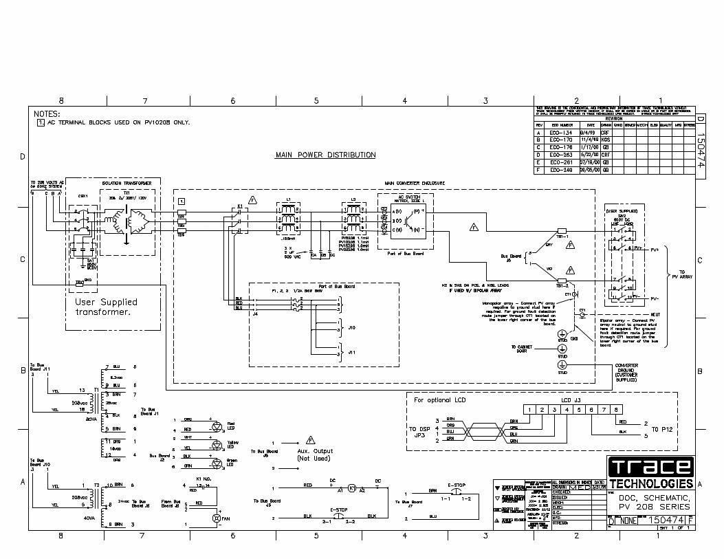
150474 Rev F : Schematic, System, Grid Tied PV Inverter, PV-Series
151121 Rev B : Assembly, Main Enclosure, Control Components, 20 KVA, PV-20208 Table of Components
151120 Rev B : Envelope Drawing, Grid Tied Inverter, PV-20208
Underwriters Laboratories Listing Document, April 25, 2000
Underwriters Laboratories Listing Card, September 8, 2000
Accessories:
151258 - Combiner Box, 10 Pole, 600 VDC, Nema 3R
151260 - Combiner Box, 12 Pole, 600 VDC, Nema 3R
151179 - Transformer, 20 KVA, 3 Pole, 60 Hz, 208 Delta/208-120V
151180 - Transformer, 20 KVA, 3 Pole, 60 Hz, 208 Delta/480-277V


Trace Technologies PV-20208 Photovoltaic Inverter
Major Parts ListAssembly Description: Main Enclosure, Control Components, PV-20208Trace Technologies Assembly # 151121
Item # Qty Reference Designator Trace Technologies Part # Description1 1 1-151139-01 Fab, Enclosure2 1 1-150691-01 Heatsink, 339.88 X 387.353 1 1-151146-01 Fab, Fan Shroud4 1 T1 1-150438-01 Transformer, 80VA5 1 T2 1-150446-01 Transformer, 40VA6 1 K1 1-150668-65 Contactor, 3P, 24VDC Coil, 65A7 1 TB1-2 1-150410-01 Block, Power Distribution, Mini 2P8 1 1-150714-01 Fan, 24VDC, 6", 240CFM, 53.3dB9 1 L2 1-150671-01 Inductor, 1.0mH, 65Arms
10 3 CA, CB, CC 1-150403-01 Capacitor, NP, 2UF, 600VAC, 6%11 1 L1 1-150665-01 Reactor, Line, 158uH, 65Arms12 1 1-150378-02 Assy, PCB, DSP13 2 1-151199-06 Conduit, Liquid Tight Connector, Zinc
151121 Sheet 2 of 2


Installation Instructions for Photovoltaic Combiner Box
Unit should be mounted in the vertical position using integral mounting tabs withappropriate hardware (not included).
MODELNUMBER
MAX DCVOLTAGE
MAX FUSESIZE
MAX SOURCEIsc
MAX RATEDOUTPUT I
CB-10H20-3R 600 20A 12.8A 101ACB-10HD8-3R 600 8A 5A 64ACB-12H20-3R 600 20A 12.8A 192ACB-12H20-4 600 20A 12.8A 192A
Wiring methods shall be in accordance with National Electrical Code, Article 310 and690, ANSI/NFPA 70. Copper conductors only, 75°C.
Wiring requirements are as follows:
MODEL NUMBER SOURCE WIRE RANGE OUTPUT WIRE RANGECB-10H20-3R #14 to #8 #6 to #2CB-10HD8-3R #14 to #8 #6 to #2CB-12H20-3R #14 to #6 (2) #14 to (2) 1/0CB-12H20-4 #14 to #6 (2) #14 to (2) 1/0
For Model numbers CB-10H20-3R and CB-10HD8-3R reference attached drawing forappropriate output wire routing requirements.
Chassis ground may be accomplished using supplied ground screw in base of unit.
Recommended tightening torque (pound-inch):
#18 - #10 #8 #6 - #3 #2 #1/020 25 35 40 50
FIRE HAZARD-When wiring is complete, check all terminal screws for proper torque.
A SUITABLE DC RATED SYSTEM DISCONNECT SHALL BE USED INCONJUNCTION WITH THE INSTALLATION OF THIS EQUIPMENT.
Copyright Trace Technologies Document # D07200 Rev B. Sept. 27, 2000
Trace Technologies Corporation3547C South Higuera Street
San Luis Obispo, CA, USA 93401

Copyright Trace Technologies Document # D07200 Rev B. Sept. 27, 2000

