operation and maintenance manual … · operation and maintenance manual with illustrated parts...
TRANSCRIPT

OM-2013B
! _..- - __..,.
3
1
OPERATION AND MAINTENANCE MANUAL
with
ILLUSTRATED PARTS LIST
for
SOLID STATE FREQUENCY CONVERTER
60-kVA, 115/200-V, 3-PHASE, 400~Hz
SPECIFICATION NO.
408300B-1
408468
INPUT MODEL NO.
480-V, 3-PHASE, 60-1~ 60SB-61
380-V, 3-PHASE, 50-Hz ~OSB-51
OPTIONAL KITS
PART NO:
489395
489403-I
489404-l
489404-2
489405
489448
489949
RATED OUTPUT:
FOR:
Rain Shield Assembly
Trailer Mounting
Bridge-Mounting (Narrow)
Bridge-Mounting (Wide)
Forklift Mounting Assembly
Floor-Stand Mounting Kit
Stop/Start Interface Assy. (TO-17O)
Hobart Brothers Company Power Systems Division
Troy, Ohio 45373


, / .
: ---. -....-- -.~~- .-- -- ------.-- S-~~TY-~INST~~OmS-~-~~~S~~R ELECTRICAL POWER EQUIP?@hT
ELECTRIC SHOCK can kill. Do not touch live electrical parts.
ELECTRIC ARC FLASH can injure eyes burn skin cause equipment damage and ignite combustible material. Do not use power cables to break load and prevent tools from causing short circuits.
IMPROPER PHASE CONNECTION, PARALLELING, OR USE can damage this and attached equipment.
IMPORTANT: - Protect all operating personnel. Read, understand, and follow all instructions in the Operating/Instruction Manual before installing, .
operating, or servicing the equipment. available for future use by all operators.
Keep the manual
A. GENERAL
B.
Equipment that supplies electrical power can cause serious injury or death, or damage to other equipment or property. The operator must strictly observe all safety rules and take precautionary actions. Safe practices have been developed from past experience in the use of power source equipment. While certain practices below apply only to electrically-powered equipment, other practices apply to engine-driven equipment, and some practices to both.
SHOCK PREVENTION
Bare conductors, or terminals in the output circuit, or ungrounded, ' electrically-live equipment can fatally shock a person. Have a certified electrician verify that the equipment is adequately grounded and learn what terminals and parts are electrically HOT. Avoid hot spots on machine. Use proper safety clothing, procedures, and test equipment.
The electrical resistance of the body is decreased when wet, permitting dangerous currents to flow through it. equipment, do not work in damp areas.
When inspecting or servicing
dry wood, Stand on a dry rubber mat or
use insulating gloves when dampness or sweat cannot be avoided. Keep clothing dry, and never work alone.
1. Installation and Grounding of Electrically Powered Equipment
Equipment driven by electric motors (rather than by diesel or gasoline engines) must be installed and maintained in accordance with the National Electrical Code, ANSI/NFPA 70 and other applicable codes. .A power disconnect switch or circuit 6 reaker must be located at the equipment. Check the nameplate for volta e, only 3-phase power is availab e, f
frequency, and phase requirements. If connect any single- hase rated equipment
to only two wires of the 3-phase line. DO NOT CONNE T E the equipment grounding conductor (lead) to the third live wire of the.3-phase line, as this makes the equipment frame electrically HOT, which can cause a fatal ShOCL.--- -----_
Alwa s to K
connect the grounding lead if supplied in a power line cable, t e grounded switch box or building ground.
separate groundin lead. If not provided, use a
Ensure that the current of the grounding f ead will
(am erage) be adequate for the worst F
capacity ault current
situation. details.
Refer to the National Electrical Code ANSI/NFPA 70 for Do not remove plug ground prongs.
receptacles. Use correctly mating
2. Output Cables and Terminals
Inspect cables frequently for damage to the insulation and the connectors. not overload
Re lace or repair cracked or worn cables immediately. : Do : ca les. i
energized. Do not touch output terminal while equipment is ;
,
3. Service and Maintenance
Instruction 910082 Feb 25186 Revised
Page 1

I \
. /’ I / ‘z
I z i ! A---- :
/ \
/’ i
I “‘A .N/
I B&e inspecting or servicing electrically-powered equijpment
"--A/ - --
..take th'e followln <--Y---.----------- precautions: g -_x_-II - -L-
-!- a. Shut OFF&l power at the disconnecting switch or l&&%reaker before inspecting or servicing the equipment. ----------------------~-~-
FI -
Fi ma UII
1.
3 AND EXPLOSION PREVENTION
5 and explosion are caused by electrical short circuits, combustible trial near engine exhaust pi ing, misuse of batteries and fuel, or afe operating or fueling con itions. 8
Electrical Short Circuits and Overloads
Overloaded or shorted equipment can become hot enough to cause fires either by self destruction or causing nearby combustibles to ignite. For electrically-powered equipment, in particular, input protection to remove short circuited or heave -P
rovide primary
equipment from the line. y overloaded
2. Batteries
Batteries may explode and/or give off flammable hydro en and arcing from a ruptured battery can cause fires an 8 ad%sion%e acid failures. When servicing, do not smoke, cause sparking, or use open flame near the battery.
3. Engine Fuel
Use only approved fuel container or fueling system. Fires and explosions can occur if the fuel tank is not grounded prior to or during fuel transfer. Shut unit DOWN before removing fuel tank cap. Do not completely fill tank, because heat from the e uipment may cause fuel expansion overflow. Remove all spilled fuel 4 that penetrates the unit. After clean-up,
MMEDIATELY, including any
fumes away with compressed air. open equipment doors and blow
TC -
:z Ne
CC FUME PREVENTION
Don monoxide i Engine exhaust fumes can kill and cause health problems. I or vent the exhaust fumes to a suitable exhaust duct or outdoors. zr locate engine exhausts near intake ducts of air conditioners.
BO - ILY INJURY PREVENTION
ious injury can result from contact with fans inside some equipment. # t DOWN such equipment for inspection and routine maintenance. When ipment is in o eration use extreme care in doing necessary troubleshooting; adjustment. g o not remove guards while equipment is operating.
ME -
Fi
5; in:
ICAL AND FIRST AID TREATMENT
;t aid facilities and a qualified first aid person should be available : each shift for immediate treatment of all injury victims. Electric zk victims should be checked by a ph sician and taken to a hospital zdiately if any abnormal signs are o served. 1
1 I
b. Lock switch OPEN (or remove line fuses) so that power cannot be turned ON accidentally.
C. Disconnect power to equipment if it is out of service.
d.. If troubleshooting must be done with the unit ener ized, another person present who is trained in turning o f
have f
and providing or calling for first aid. the equipment
EMERGENCY FIRST AID
Call physician immediately. Seek additional assistance and use First Aid techniques recommended by American Red Cross until medical help arrives.
j 1
IF BREATHING IS DIFFICULT give oxy en, dotm.. 2
if available, and have victim lie FOR ELECTRICAL SHO&K, turn o f power. Remove victim; if not
bneathing, begin artificial respiration, preferably mouth-to-mouth. If n detectable pulse,
.S illa g-d- ffiiiEi*l~2~. begin external heart massage. Call Emergency
-Ed-T _EBECAITTIONARYIdABEU m ent mont?ily;-
F_ "~ -_ 1
rep I precautionary labels on'the Gui
are-all- abels that cannot be easily rea r . --_- - . _
Page 2 Instruction 910082 Revised Feb 25186

TABLE OF CONTENTS
CHAPTER/SECTION j
Description/Operation
Description
1. General
A. Mountings for the Solid State Converter
B. Advantages Offered by Solid State Converter
2. Theory of Operation
3. Orientation
4. Detailed Description
A. Controls and Control Circuits
B. Description of Front Panel Controls
c. Converter Cabinet
5. Optional Equipment
A. Trailer-Mounting Kit
B. Bridge Mounting Kit, Narrow
c. Bridge Mounting Kit, Wide
D. Rain Guard Kit
E. Floor Stand
F. Forklift Mounting Assembly
Preparation for Use
1. Receipt of Inspection of Equipment
l-l
l-2
2. Installing the Bridge-Mounted Unit
A. General
B. Drilling Holes for Mounting the Unit
c. Mounting the Unit
- ._. _ _.. _, -May_ .2.2/g 6. _ ._ ._ _ . . . . Content?
-- -._ . ̂ _ _^. -- ._ _ --.-- - - -. II___

TABLE OF CONTENTS (CONTINUED)
SUBJECT CHAPTER/SECTION PAGE
3. Converter Unit Mounted on Floor Stand l-2 61
4. Trailer-Mounted Converter Unit 61
5. Wiring the Converter Unit 6;
Operation
1. Start-Up Procedure With No Load on l-3 Converter Unit
1;
2. Start-Up Procedure with Converter Unit 1; Connected to an Aircraft
3. Turn-Off Procedure 2! ,
2-l Servicing
Maintenance
1. General
2. Field Maintenance Procedure
3. Service Information and Factory Repair
4. Trailer
Troubleshooting 3-l
Procedures
1. General
2. Procedure for Restoring Unit to Operation After a Fault
A. Undervoltage Fault
B. Overvoltage Fault
c. Overcurrent (Short) Fault
D. Overcurrent (125%) Fault
E. Overcurrent 150% Fault
F. Phase-Loss
1;
I!
1;
1:
2:
2
1'
I!
1;
1:
1:
lj
21
21
2i
L -p-age f! _- ..- .__ 1 ._-_----I__

_
CHAPTER/ FIGURE SECTION NUMBER
l-l 1 Frequency Converter Unit l-1 2 Specifications and Capabilities l-l 3 Block Diagram l-l 4 Card Cage (Front View) l-l 5 Control Panel l-l 6 Converter with Rain Guard Assembly
l-2 1 Bridge Mounted Converter l-2 2 Installation Diagram l-2 3 Converter Mounting Brackets and Hardware l-2 4 Converter Unit on Floor Stand
2-l
3-l
4-l 4-l 4-l 4-l 4-l 4-l 4-l 4-l 4-l 4-l 4-l 4-1 4-l
-..-. .--. ..__~ May 22./86
I^.-- -.. .-. .__ _ I_ ._ _.. _
LIST OF ILLUSTRATIONS
TITLE
1 Lubricants 2 Symbols & Time Intervals 3 Lubrication Chart
No Illustrations
1 AC/AC Converter 2 Main Frame Assembly 3 AC/AC Converter (Front Interior) 4 AC/AC Converter (Rear Interior) 5 Control Panel Assembly 6 Inverter Assembly 7 Rectifier Module 8 P.C. Card Cage Assembly 9 Converter, Trailer-Mounting Assy. (Option) 10 Converter Bridge-Mounting Assy. (Option) 11 Rain Guard Assembly (Option) 12 Forklift Mounting Assembly (Optional) 13 Floor Stand Kit
PA( NO -
2 3 4 7 9 1:
3 4 5 7
3 3 4
li
3 4 6 8; lo: 12 1% 16 18
29 22 24 2”
--------- -----ag*A

This page intentionally left blank.
[.. - ..^ “.. _- -..-- __. -~ --...- _---. .-----._.--x.---.-. .-- _.......____ ._- ..- _..___..-_ ~_ _____ t .-
; Contents - ..-. -.. .----. .~ ~..._ __.. ..-. - -._....-. . ..__ ~. __. _. ._... _ _.. _. .._. ."_, .__ May 22/86]
i- _.Page_ 4 _ _.^- __ ._ ..- ..------

-
1.
2.
3.
4.
_._ -. __ ---- -
INTRODUCTION
Scope
This manual contains operation and field maintenance instructions for soli/d state frequency converters manufactured by Hobart Brothers Company, Power / Systems Division, Troy, Ohio 45373, U.S.A.
The purpose of this manual is to provide information and instructions to ) experienced operators and maintenance personnel who have not previously been exposed to this equipment. electricity or electronics.
This manual is not intended to be a textbook
Arrangement
This manual is divided into four chapters. Each chapter is divided into sections as required. Each section starts with page 1. Each page is, identified by chapter, section and page number in the lower outside come Illustration numbering is also grouped by sections. I
When a reference is made to material which is located in the same section the material is identified by paragraph location only. Example: (Para. A). When referenced material appears in a different section, it is ( identified by chapter, section, and paragraph location. Example, (See 2- Para. 1A). The same method applies to illustrations which are identikied figure numbers. Examples:' (Fig. 8), or (2-l; Fig. 8). 1
Service Information
If you have any questions concerning your Hobart Power Systems Division Equipment , you are invited to contact our Service Department by mail, telephone, or TWX.
Write: Hobart Brothers Company Power Systems Division Service Department / Troy, Ohio 45373 U.S.A. b
Call: Area Code (513) 339-6000 Extension 4276
/ TWX: 810-456-2907
. . .^ - “. . -_. __ -.- - . ~----------
'n
'.
,
.
;
on
1

This page intentionally left blank.
I__^ _., __ F_,------ _._ -.-~ ..-..
f
_ I ~____. _... ___ _ .~ __ ---
-,
1 Introduction
!L ..Fage.- 2 __ - .._ ~ -.-- ---_-.-.--_
_- -*.._ ,.P i ,-+’
‘--..* --
,~,,. - : .r.
,_ ,.‘. j b *I 4.
’ ,” -. _ .-r _-. .- _. ._ _ _-. ._
“, ̂ OM-2213 ._.._ .._~ ..- --.- ~,_ 2:
CHAPTER 1. DESCRIPTION/OPERATION
SECTION 1. DESCRIPTION
1. General
The solid state converters covered by this manual are designed to provide power for maintenance and starting of aircraft having 115/200-V AC, 3-phase, 400-Hz electrical systems. These converter units are identified by Specification Numbers 408300B-1 and 408468 and are manufactured by Hobart Brothers Company, Power Systems Division, Troy, Ohio 45373. See Figure 2 for unit specifications and capabilities. /
A. Mountings for the Solid State Converter I
The solid state frequency converter may be mounted in any one of/three ways: on an optional trailer to make it mobile, on a steel floor!stand (also optional), or on a passenger boarding bridge at an airport; See paragraph 5.
B. Advantages Offered by Solid State Converter I /
The solid state converter offers numerous advantages when compared to motor-generator type power units. The main advantages are as follow:
(1)
(2)
(3)
(4)
Energy Savings
Because the converter unit is a demand system, it consumes only the energy necessary and in the amount required. If no aircraft is being serviced, no power is required, and thus none is t generated or consumed.
Efficiency
The converter unit provides power to an aircraft at an efficient of 95% or better, with 1% voltage regulation at the aircrafk. Since the unit is used in the vicinity of an aircraft being; serviced, expensive 400~Hz cabling is kept to a miminum andin external line drop compensation is required. /
Longer Service
The solid state converter operates for longer periods of time without service than do motor-generator units, as there are; no moving parts to wear out and thus impair the unit's operation.
Less Space Required
The converter unit is much smaller in physical size than a motor-generator unit of comparable output, and thus requireis les space when bridge-mounted or floor-stand mounted.
Y

1. Front heat sinks 4. Cabinet 2. Control panel 5. Rear heat sink 3. Card cage access door 6. Front assembly (door)
Frequency Converter Unit Figure 1
_ __ .,
L. ..Rage 2 .- ~_ ._ _---- __^. -__

Bridge-Mounted Unit
Weight (approximate, with mounting brackets) Width (front to back of unit) Length (overall, with long mounting brackets) Length (overall, with short mounting brackets) Height (overall)
1734 pounds (786;Kg) 48.5 inches (1232 mm) 83.6 inches (2124 mm) 71.5 inches (1816 mm) 16.25 inches (413imm)
Trailer-Mounted Unit
Weight (approximate) Width (overall) Length (with cable hangers) Height (overall)
2128 pounds 54.5
(965;Kg) inches (1384 mm)
82 inches (2083 mm) 37.25 inches (946rmm)
I
Stationary Unit *
Weight (approximate, without mounting) Width (front to back of unit) Length (with lifting eyes) Height
I I
1660 pounds (753;Kg) 48.5 inches (123$ mm) 69.5 inches (1765 mm) 16 inches (4061mm)
Electrical
Input Part No. Part No. 408300B-1 408468
Volts (AC) 480 Amperes (at rated load)
380, 75A 97,
Frequency (Hz) 60 50. Phase/Wire 313 313;
output
Volts (AC) Amperes (at rated load) Frequency (Hz) Output Power Rating (kVA) Power factor (PF) Duty cycle (X) Overload relay
115/200 (wye); 173 400 60 .80 100
125% for 5 minutes; 150% for 10 seconds
* (Basic unit dimensions: 48.5" [1232 mm] wide, 63.5" [1613 mm] long (with lifting eye), and 16" [406 mm] high).
I
Specifications and Capabilities / Figure 2 - ----- _____________
May 22186 - . ..-..-- ---.- -.-. -. - -- -- - __.__-..

I (5) Lower Noise Level i ! I The converter unit, being solid state, is much less noisy in
operation than motor-generator (rotating) equipment.
2. Theory of Operation / This solid state frequency converter employs all silicon semi-conductors and CMOS digital logic. components of the system.
The block diagram in Figure 3 identifies major The input voltage is first rectified in a 3 phase'
bridge configuration and then filtered to provide an unregulated DC voltage of approximately 600-V. This DC voltage feeds a three phase inverter which transforms the DC input into a 400-Hz regulated output voltage. The inverter output transformers provide electrical isolation between the input and output.
AC INPUT -
46o-v, 60-HZ - ct - 380-Vy50-HZ -
AC OUTPUT 115/200-V 400-HZ
RECTIFIER DC FILTER 30 INVERTER TRANSFORMER OUTPUT FILTER
Block Diagram of Converter Figure 3
The inverter employed in this system is a step wave-form inverter. This inverter uses harmonic neutralization, which results in the elimination of all harmonic distortion below the eleventh harmonic without filtering. The system consists of six identical bridge type inverters (N=6) which are uniformly staggered 30 electrical degrees apart (180/N). In this arrangement, the smallest harmonic is 2N-1. A small filter is used to reduce the amplitude of eleventh and higher harmonics to the desired level. The power level of each of the six inverters is total kVA output divided by six.
Bach of the six individual inverters consists of a transistorized bridge and a snubber circuit. A variable width square pulse is obtained on the AC-1 : and AC-2 terminals by turning on the transistors Ql and 44 or 43 and 42. i The snubber circuit consists of a pair of air cores (LlOl and L102) and a j
/ brinted circuit board containing diodes, capacitors and a dissipative i
h. .- - .- element, Rl. -.r,w--- -_.-______.
l-l ; i",". -. _, __.- _...__ _____.. --..- .___.____
r.. Rage 4 - " . .., ..- .-_ _ .._
~----_--_--.-. --~ _-_._ dt--- May 22/86
..- -.-- ---.--.- - - ._--. ~_._...__ ___... ~._ _._.__... __
--.--- i^ -. __.-. - .,____..__

_,_, _ ’
! *, .’ ._ _. ,- . ‘.c .-_--- _ -...-. ~----- ----.- -_-_--__ -.__ --___--.- ..-. -------- _ ___.__
Each inverter transformer has three AC output windings. These windings are connected in series with the windings from the other inverters to yield a low-distortion output. Each leg of the three phase system is comprised of one winding from each of the six transformers. See Drawing 907226. I
As the phase shift between the six inverters is digitally generated, no change - and consequently no harmonic lower than the eleventh - appears when the line or load is varied, regardless of pulse width variation. j Because of the elimination of the lower harmonics, the output filter becomes very simple.
The output filter consists of a series choke and parallel capacitors (L2, L3, L4, Cl3 to C24 on Drawing 907226). The output voltage is sensed and regulated through a negative feedback loop which contains sensing transformers T7, T8, T9, and related circuitry in the amplier board. j
A. Protective Circuits
Current transformers TlO, Tll, and T12 provide an output current reading to the amplifier board, which compares it with various thresholds 'on alarm board No. 2. At about 180% of rated load, the unit begins current limiting, and the voltage begins to drop off. The control circuits monitor output voltage and output current, and sense various thresholds in voltage and load current to assure the protection of the system as well as the load. When an overvoltage condition develops at the output (voltage exceeding 130-V AC), the unit will shut down. When an overload condition develops, wherein the load exceeds the unit's power rating by 25%, the unit will run for approximately 5 minutes before shutting down. For a 50% overload, the unit will turn off after approximately 10: seconds. In case of a short circuit, the unit will turn off to avoid damage to its components. Protective devices and alarms are described, in detail in the following paragraphs.
Orientation
To avoid confusion in the location of components, the control panel of the' unit is located at the FRONT of the unit. LEFT and RIGHT are determined by looking at the unit from the FRONT. I
Detailed Description /
A. Controls and Control Circuits
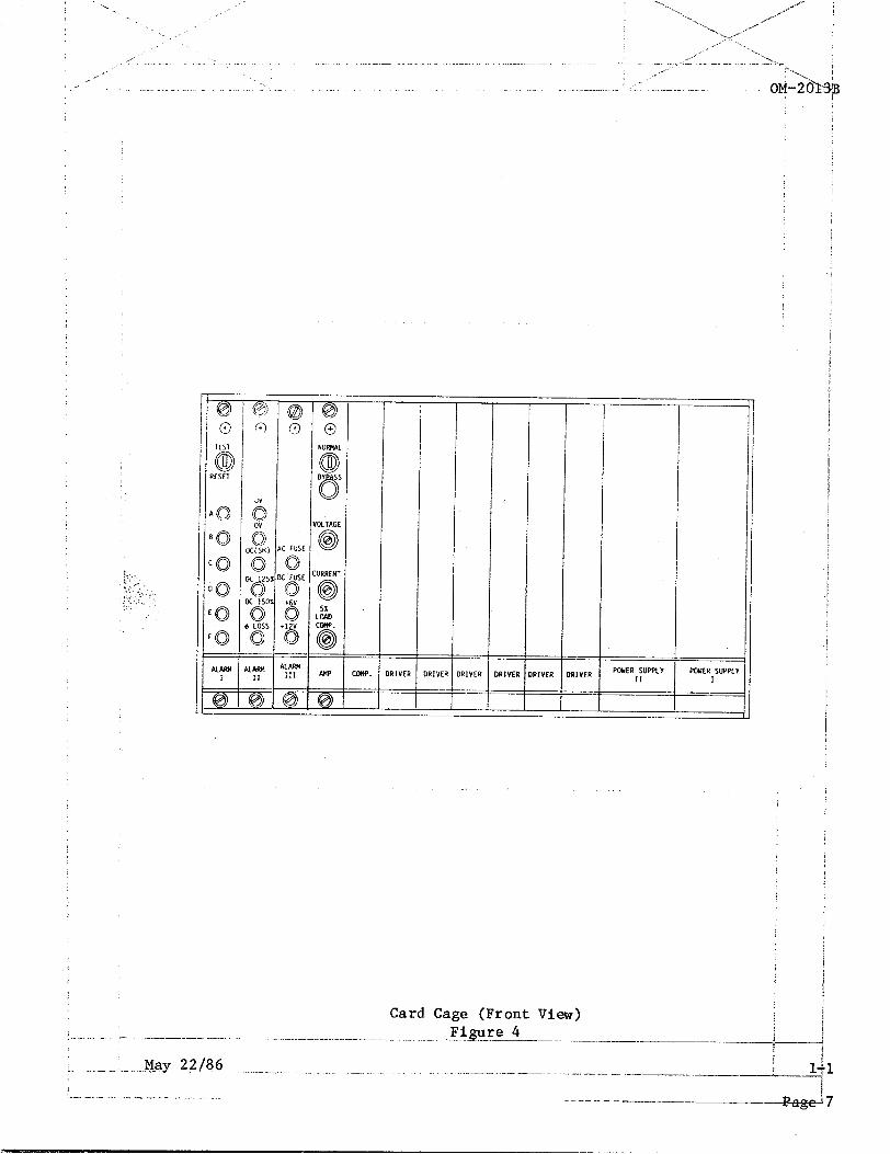
All control boards are concentrated in the card cage, which is : : accessible from the front of the unit through a small hinged door located just beneath the control panel. See 3, Fig. 1. All control : circuits are solid state and employ CMOS technology for low power consumption and good noise immunity. There are 13 boards in thejcard cage (Fig. 4) which are divided into three groups:
Control boards (2) Alarm boards (3) Power supply and driver boards (8)
_ -” ._ . . . bC_ ---- --- -.._--...- --.-_ -_---- t
1 May 22186 _--___
--------<- 1
5

(1) Control Boards
Amplifier and comparator boards generate the driving pulses for / the power transistors. The amplifier board contains an oscillator, error amplifier, and slow start circuit.
The amplifier board allows for adjustments to the output voltage ! as well as to the load compensation. The voltage potentiometer allows an operator to adjust the output voltage in excess of + 15%.: By setting the output voltage at a low of 100-V or a high of i-32-V, the undervoltage and overvoltage alarms should be triggered. In this way, the presence of the protective thresholds is tested. A 1 clockwise rotation will increase the output voltage.
Another adjustment on the amplifier board is the load compensation.; At full load this adjustment will increase the output voltage by upj to 5%, to compensate for the voltage drop on the cable connecting the load. A clockwise rotation on the potentiometer will bring the! compensation at full load from 0% to 5%.
Also on the amplifier board front panel, a two-position toggle ) switch allows maintenance personnel to operate the unit for test f purposes without connecting the output cable to an aircraft. When I this switch is in the "AIRCRAFT/NORMAL 11 position, the interlock circuit is activated and the unit will run only if the output cable is connected to an aircraft. In the "BYPASS/MAINT" position, the I unit will turn on and stay on even if the output cable is not connected to an aircraft. A red light next to the switch will i indicate that the aircraft is disconnected and that the "BYPASS/MAINT 11 position on the toggle switch should be used in order to turn the unit on. The current adjustment potentiometer : determines the point at which the unit goes into current limiting.
(2) Alarm Boards
The alarm boards monitor a number of sensors and give signals I indicating the nature of a fault when a fault occurs. Faults in . the unit are indicated by red lights (LEDs) which may be observed i through a small window in the card cage access door (3, Fig. 1).
Alarm No. 1 monitors a series of current sensors. This device will sense a current in excess of normal in the transistorized bridge :
and will turn the entire unit off. These sensors will react only to an imminent failure of the transistors and not to an overload. : A panel-mounted three-position switch allows an operator to test if the alarm circuits are functioning. The reset position will bring' the circuits back to normal.
!m, - - -_ +--- ---
,-.*y1 i
-A---.j my 22/86; 1
- .. .-~^---.-^--- -- _-- -.--------- ._.__ -__---.-_--. --_ ._ .._
h.. -.,... _ ,.,,. _
- -_---.-.-.. .-. .._._. __ - ..- -_ -I^--~ ------.-.--- i -._.._. - i Page 6 L .- .-. .-, ,_" _
2. )’ . . _. c: _, i;: ,. .; - i-.. :., , ..
RIVER RIYER RlVER
- -- ‘I ---l
j/
PWER SUPPLY I
I
Figure 4 Card Cage (Front View)

. . . i __,-
..“.- _- “_
Alarm No. 2 monitors output voltage for an over-or under-voltage i condition, for output current at three levels of load (125%, 150%, and 200%), and for the loss of an input phase. The undervoltage light will latch only if the undervoltage condition longer that 7 seconds to allow for voltage transients when applying heavy loads. All thresholds are factory-set and additional adjustment is not necessary. The I potentiometer for these thresholds are in the alarm board and are not easily accessible. All of the lights on alarm 1 and 2 boards are red and have a latching circuit which allows for an investigation even after the cause of a fault has disappeared.
Alarm No. 3 has only green indicators signalling the presence of the internal voltages (+6V and +lZV) and the integrity of the DC fuses.' When the +12V green light is on, the control circuits on all boards; are powered. The +6V light indicates the proper functioning of power supply No. 1 board.
(3) Power Supply and Driver Boards
The function of power supply boards No. 1 and No. 2 is to generate khe voltages necessary to drive the power transistors. Power supply No. 1 is a high frequency DC to DC converter which provides regulated +6V and -6V from an input of +7OV. This output is used to drive all of the transistors with the emitter connected to the -600V bus. To drive :the rest of the transistors, power supply board No. 2 provides sets of j floating +6V sources. Internal wiring brings these voltages to each of the driver boards.
Description of Front Panel Controls
The front panel controls and indicators for the system are shown in Fig. 5. The function of each of the controls and indicators are as follows:
(1) Start Button After the unit input power is turned on and any of the alarms is reset, by pressing the START button, the;unit will turn on. (See start-up procedure).
(2) Stop Button The unit can be turned off by momentarily pressingjthis button.
(3) Input (Green) This indicator light will turn on upon application of input power.
(4) Output (Green) This indicator light, by turning on, indicates the; : presence of power at the output terminals.
: ,
, r - X. - .<- ---- ~~---- ----- --,-. -.----.- . ..-- --- -,-- - .-.-- -__--
i _______- 1 I ,---
l-l May 122/86i : ., . - . . ..- .-..- -- --.-.-.-- ----.-~-. -. _ - -... --- .-._ -.._ __ _, ..-. ..-~---. :
- . . . _ 4
L P.qxe 8 i .-- . . I_ .-.. .-. . ..- - - ..,_ ^ - __. _~ .~ ----__-- _-.. ..---.-_ ..__,. .-II

‘. I__ ’
j _-‘
\ ,c ,,, .” OM72013B \' ___.--_-I . . . . _~~ -...--. --- .-
RESET 0
START
0
INPUT POKER
cl
@
OUTPUl
OUTPUT POWER @
0 FAULT
STOP a' f=J,
OUTPUT VOLTAGE
Control Panel Figure 5
(5) Voltmeter
(6) Reset
This meter, in conjunction with the phase switch, measures output voltage on all three phases, with an accuracy of 2%. Two test point jacks are provided next to the voltmeter for measuring; voltage with a more accurate meter if that is required during service.
This button permits the reset of alarms without opening the accesd door to the card cage. This button is especially necessary khen 1 the phase loss alarm will latch due to a temporary failure ia input power. 1
L-. I -. .- -. )-.----.--- -----------._-____-._--_.. --__-- j May 22/86
:- . -. . ..-.- _--- --.--. ------- ..-. .._ _,._ -_--. -.._---- -__-. .- .-. . . .-.-.__------- ---. ..- .- --.--- .l_._l.___.-.. ---I .-.. .-_-_. !
i - .^ _-.. _ .“. .., ^- .-- . ..1 “,. Page _% ----I .- - .- --.-.- .~ -__--__-- _.- ___ ^__

The cabinet which houses the converter apparatus and circuitry consists of a sturdy welded steel frame to which a one-piece 16-gage sheet metal cover (4, Fig. 1) is fastened, and to which a flat metal sheet is attached to form the bottom of the cabinet. The entire front assembly' of the unit is hinged at the bottom to permit opening the unit for access to control components in the front interior of the unit. Panels at the rear of the unit are attached by screws.
The converter unit is convection-cooled. Air enters the unit from the. bottom and leaves through the top.
Power cables enter the unit from the right rear (or left rear, as viewed from the back of the unit). These cables are secured to the unit by two clamp assemblies mounted in the small panel at the rear of the unit. 1
5. Options
The following option kits are available for use with the converter: I
A. Trailer Mounting Kit (Part No. 489403-l) /
This trailer kit permits a converter unit to be towed to and used at ; different locations at an airport.
B. Bridge Mounting Kit, Narrow (Part No. 489404-l)
This kit consists of a set of four metal brackets sized for mounting the converter to the underside of one model of passenger boarding bridge, , between the supporting I-beams of the bridge. This particular kit : mounts the converter to bridges whose supporting I-beams are 66-l/8 j
. inches apart. See section l-2, Figures 1 and 2.
c. Bridge Mounting Kit, Wide (Part No. 489404-2)
This kit also consists of a set of four metal brackets. This particular kit mounts the converter to passenger bridges whose supporting I-beams; are 78-l/4 inches apart. See Section l-2 Figures 1 and 2.
D. Rain Guard Kit (Part No. 489395) I
See Figure 6. This kit protects the converter from rain. It consists' of (1) a metal hood-type cover which mounts over the convection-cooling holes in the top of the converter, and (2) a lexan (plastic) cover which protects the converter control panel. i
; Page 10 i- -.. . _-. ._. _. _ I

i Converter With Rain Shield Assembly I -- .- 1:.. ._ _i. ,.*'---. -.--- -.-~~-. -.- -- --- --.--.---.~-~---~~--- -~---.----. ~__ Ei.ureL~-~~~-
>_ _. - . - -^ .-, __. -- ,- ~. . . _- _-..---.^ --F
1
1

E. Floor Stand (Part No. 489448)
See Section l-2, Fig. 4. When mounted on this floor stand, the converter unit may be used as a stationary unit in a hangar or other I aircraft maintenance facility. This floor stand consists of two sturdy steel bracket-type supports which mount to the ends of the converter : cabinet.
F. Forklift Mounting Assembly (Part No. 489405)
This is an assembly which can be mounted to the bottom of a converter I unit for safely moving and transporting it with a forklift-equipped vehicle. This assembly consists of two heavy steel channels with welded steel brackets near each end. See Section 4-1, Fig. 12. ,
I
_I_-. I ..-. - .-.. -._-.._-.- -~... .__. ---V.-i
1-L .._. .., ^.. ^, .,~ .-... ._ ..__.... _ _ -- __.._ Yg22/si6 1
LP.age.12~~....... .- i -- ..,.- - - - ______

t
e’
SECTION 2. PREPARATION FOR USE
1. Receipt and Inspection of Equipment
The solid state converter unit has been thoroughly tested and inspected a the factory, and prepared for shipment in accordance with standard i industrial practices for safe shipment. Upon receiving this equipment, inspect it as follows.
A. Visually inspect the shipping crate for damage. If any damage is detected, request that the carrier agent inspect the shipment and not1 the damage on the delivery receipt. This is for your protectioni
B. If there is no obvious damage to the shipping crate, unpack the unit and save the shipping container until the unit has been put into/ service and determined to be operating correctly. Take care to avoid damage to the equipment if bars, hammers, etc. are used in uncrating.
c. Visually inspect the unit for evidence of external damage such af damaged sheet metal, scratches, broken meter faces, or damaged I switches.
If the equipment has been damaged in transit, file a claim for damage at once. If you require assistance with a damage claim, furnish:Hoba Brothers Company with full information about the claim.
ii
2. Installing the Bridge-Mounted Unit
A. General
It is important that the following installation instructions be read carefully and in their entirety before attempting to install thei converter unit to a passenger boarding bridge.
The unit for bridge mounting consists of the basic converter with brackets which fasten the unit to I-beam type supports beneath ai passenger boarding bridge (See Figure 1).
/
B.
Two different sets of brackets with attaching hardware are availbble from Hobart Brothers Company for mounting the converter, the choice o brackets depending on the distance between I-beam supports on two standard models of Jetway bridges. One set of brackets (Hobart Part No. 489381) mount the unit to I-beams which are 66-l/8 inches apbrt. The other set of brackets (Hobart Part No. 489378) mount the unit to I-beams which are 78-l/4 inches apart. (See Fig. 2). I
Drilling Holes for Mounting the Unit ,
As indicated by the dimensions given in Figure 2, when holes ar4 properly drilled, they will be 14 inches apart on each I-beam, &nd l-1/4 inch from the inner edge of the I-beam. I
! , 1
May ..22/86..--.. ._. __.. - ..~ 1 i ..- --.. _ ----. -. - -p_ll_ ---IiF+

After determining the best location for the converter between the I-beams, drill 9/16-inch holes at the points specified. Make certain j when drilling holes that the holes on one I-beam line up properly ; with holes drilled on the other I-beam.
/ Mounting the Unit
Proceed as follows to install the converter unit to a passenger boarding bridge.
(1) Put the mounting brackets in place.
Before raising the converter to the point of installation, it is necessary to put the mounting brackets loosely in place. Do not j tighten the brackets to the I-beams at this point. To do so would make it impossible to raise the converter between the I-beams. Just set the brackets in place as shown in Figure 3 (left illustration) using the mounting hardware shown in this illustration and provided with the brackets.
CAUTION: MAKE CERTAIN THAT THE FORKLIFT USED IS ADEQUATE FOR RAISING THE UNIT. THE FORKLIFT USED SHOULD BE CAPABLE OF LIFTING 1750 POUNDS (7% Kg) OR MORE.
(2) After making certain that the forks of the forklift are set securely beneath the wooden skid on which the converter was shipped, raise the converter to the point of installation slowly and carefully past'the loose mounting brackets and into place.
(3) Install the mounting brackets
It is now necessary to position the four mounting brackets'such as they will be when the converter is mounted. Figure 3 (right) shows how the hardware should be used to attach the brackets to the I-beams. DO NOT torque the bolts to full tightness at this time: Allow just enough "play" to permit minor adjustments of brackets.when attaching brackets to the converter.
(4) Attach mounting brackets to converter
Bolt the mounting brackets to the sides of the converter as shown in Figure 3 (right illustration) using the l/2 inch hex-head bolts provided with the brackets (6, Fig. 3). Place a lock washer on each : bolt before screwing it in. Torque each bolt to a tightness of 60 to' 70 foot-pounds (8.3 to 9.7 Kg/meters). At the bottom of each bracket there is a hole for a l/&inch self-tap screw (8, Fig. 3). This'hole lines up with a hole in the bottom of the converter. Drive in a self-tap screw (with lock washer) at each of the four points where needed at the bottom of the converter.
1
_-__--- .- --.-.. ------___.--.-- ..---- ----_ ------__ ii -___-----. .----1,-
May b2/86/ _. ,.._ __-.. - - ~~...

. . .\ 1,
(5) Torque mounting brackets to I-beams.
Torque the two l/2 inch hex-head nuts at the bottom of each I-beam to a tightness on the threaded bolt of 60 to 70 foot-pounds (8.3 to 9.7 Kg/meters). /
(6) Remove wooden skid from bottom of converter.
(7) Connect Power input and output cables. Refer to Paragraph 5.:
r
II I- PASSENGER BOARDING BRIDGE
hOLID STATE
CONVERTER
UNIT
Bridge-Mounted Converter Unit Figure 1 .--
.: May 22/86
1”” . .-.. _ ,_ __ -- ._I _ -._._- _. ._ ,. .___. ____ Page 1 ___-.-- . ..-. - _.~ -_

Converter Unit (Front View)
UNIT WITH i WIDE :
MOUNTING / BRACKETS ;
t- 66-l/8” _j
UNIT WITH NARROW
MOUNTING BRACKETS
I-Beam
$i ii;: &Y: I I
I ' I * Converter
Unit
0 o (Side View)
\ I Mounting Brackets
SIDE VIEW OF UNIT
* On-center distances between holes to be drilled between I-beams. ** On-center distances between holes to be drilled on each I-beam.
Installation Diagram Figure 2
I -..- 1-2 ^ . . - - .___. .._.. . . ..__ May 22j/86
L... .-page 4.-- . .._ . . ---- - - _-----_

MOUNTING BRACKET ASSEMBLY BEFORE CONVERTER UNIT IS RAISED INTO POSITION AFTER UNIT IS INSTALLED
1. Passenger Bridge I-beam 2. Converter Unit 3. All-thread Bolt, l/2-inch 4. Hex-nut and washer, l/2-inch
1 I 5. Rubber Shock Mount 6. Mounting Bracket 7. Hex-head bolt, l/2-inch 8. Self-tap Screw, l/4-inch i
i
Converter Mounting Brackets and Hardware i
Figure 3 . j
.__ _ _. F,.~ -.--.-... ~- ..-..- .-.~ -.-.... ._. -.~ -... ..- _ ._. . .._.. __... -. . .._.. - -
k . -. May 22/86
I... .._ ._,. .- __
1.
Page
2
5

3. Converter Unit Mounted on Floor Stand
No special problems regarding installation are to be encountered when installing the converter when it is mounted on a floor stand. When locating the stand-mounted converter, it should be placed such that there ' is adequate air circulation around it. mm) of free air space around it,
Provide a minimum of 12 inches (305 and make sure that the convection-cooling!
holes in the top and bottom of the unit are not obstructed.
See Paragraph 5 regarding installation of converter power cables. I
4. Trailer-Mounted Converter Unit
Because this unit IS trailer-mounted, there is no installation per se, except the installation of power cables. When placing the trailer-mounted! unit where it will be used, two things are important:
A. Make certain that there is adequate air circulation - 12 inches (305 ! mm) or more - around the unit, and that the convection cooling holes at the top and bottom of the unit are not obstructed.
I
B. Make certain that the trailer parking brake is securely locked before ! operating the unit.
See Paragraph 5 regarding installation of converter power cables. ;
5. Wiring the Converter Unit
Wiring of the unit is limited to installation of power input and output cables, and possibly the wiring of a remote control.
Wiring, as with other aspects of installation, is done by personnel provided by the Hobart ground power equipment distributor responsible for : installing the converter.

i Converter Unit on Floor-Stand
Figure 4 I
__- . . ,F .--. ~----_
May 22186 " _ _ . . ~_-- .._ ~~._.._~ _...
I . -. . . _... .- _. .
_
1. __-_-___
.-------..__ pa
2
7

::
This page intentionally left blank.

SECTION 3. OPERATION
1. Start-Up Procedure with No Load on Converter Unit
A. Apply rated input power to the converter unit from the input power source (disconnecting means). on control panel will come on.
The green INPUT POWER indicating liight Check that all green lights on Alarm
Board No. 3 are ON. (See Section l-l, Fig. 4 for location of PC boards).
B. Check functioning of all alarms by putting the interlock or TEST/I(ESET switch in the TEST (UP) position and then in the RESET (DOWN) position.
\
C. Place the NORMAL/BYPASS switch on the amplifier (AMP) board in the BYPASS/MAINT (DOWN) position. The red indicator light just below j the switch should glow.
D. Push the START button on the front panel. The green OUTPUT POWER! indicating light should glow. Output voltage should be indicated'on the panel voltmeter when the phase selector switch (below the : voltmeter) is in position (phase) 1, 2, or 3.
/
Adjustments of output voltage may be made with the VOLTAGE potentiometer located on the amplifier (AMP) board. Readings on the panel voltmeter may be verified for accuracy by connecting the leads of a master voltmeter into the test jacks marked "OUTPUT" and located next to the panel voltmeter.
2. Start-Up Procedure with Converter Unit Connected to an Aircraft
A. With rated input power applied to the converter, check that'all green lights on Alarm Board No. 3 are ON and that the green INPUT POWER light is ON at the control panel.
B. Check the functioning of all alarms by putting the interlock switch in the TEST (UP) position and then in the RESET (DOWN) position.
c. Place the NORMAL/BYPASS switch on the amplifier board in the NORMAL/AIRCRAFT (UP) position.
D. Push the START button and keep it depressed for approximately one. second. If the converter is connected to an aircraft, a 28-V DC interlock signal will be fed back to the converter to latch a relay and allow the converter to operate as long as the power output cable is plugged into the aircraft. If the cable is removed from the aircraft, ' the converter will shut off.
b CAUTION: DO NOT SHUT OFF THE CONVERTER BY REMOVING THE POWER OUTPUT j
CABLE PLUG FROM THE AIRCRAFT WHEN THE CONVERTER IS CARRYING A LOAD. DAMAGE TO PERSONNEL, CONVERTER OR LOAD COULD RESULT. 1
I I .” __ - - -,i-. -~.~-.--_-.~--.- ---.-. --..----__----.--- -.___ I_~-.-~ --... -__I-d
!;, May 22/86 ; l-31 - .,,'-- .-.. ,---.. -.- .,.--.-... f - . . -. -. .-- ._ ____.... -- ____ _. .~. . . .- .-.-. .-.~-- . ..~_ - -- ..- - _. ._--.-___-- .._ __ ..-'. - ._- .j
!.‘, Page $ . ,.._ ._., -. .__" __., -. _. -. _ -.. _^. --__-_-..---. - ..-.. -_ . ̂ -i
3. kurn-Off Procedure
ITO turn the unit off, depress the STOP button on the control panel. The ;
. B reen OUTPUT POWER indicating light will shut off, and the panel voltmeter :
yill indicate zero (0) volts. I
DOTE: ! /
The red fault indicator will light momentarily when the stop button : is pushed. This is normal.
--- I
May 22/86 2 ---

‘..
___---- :
CHAPTER 2. SERVICING
SECTION 1. MAINTENANCE
1. General /
The solid state converter is designed to be as maintenance free as I possible. Therefore there are few inspections and maintenance : requirements. Field maintenance of the converter should be done only by qualified service personnel, and should be limited to cleaning and : inspection of the unit and its components, and the replacement of lamps a; fuses. All servicing and repair work including testing and calibration, should be referred to the Service Department of Hobart Brothers Company, 4 to an authorized distributor of Hobart Brothers ground power equipment.
I 2. Field Maintenance Procedure
The converter should be cleaned and inspected once every six months,ior more frequently if operating conditions warrant it. with cleaning and inspection.
Proceed as foll$s
WARNING: MARE CERTAIN THAT THE SOURCE OF INPUT POWER IS TURNED OFF AND LOCKED OFF BEFORE PROCEEDING WITH ANY INSPECTION OR MAINTENANCE OPERATION WHICH COULD BRING PERSONNEL IN CONTACT WITH HIGH j VOLTAGE.
/
A. Clean dust from the interior of the converter by blowing compressed a: into the interior first from the bottom of the unit and then from the top.
B. Clean heat sinks and printed circuit boards using compressed airior a soft brush.
C. Inspect input and output terminal blocks for evidence of overheating due to loose electrical connections.
D. Inspect electrical and mechanical connections for tightness. Inspect closely all compression-type connectors.
E. Inspect printed circuit boards in card cage for evidence of overheati] such as burned resistors or capacitor. (Note that the printed ckrcuir boards are coated with a fungus and moisture-proof coating which: turn: brown on hot components. This is a normal occurance, especially:on resistors exceeding 1 watt in rating.
I F. Check and inspect all front panel components including indicator;lamp:
/
G. Inspect the long hinge at the bottom front of the unit. If this; hinge sticks and is difficult to operate, spray lubricant.
spray hinge with a good silipone I i
H. Inspect all wiring, leads, and cables. Inspect for cuts, abras&ns, and signs of deterioration and overheating. Inspect leads for b?oken
311 ‘i t
I i

., ‘. ,”
_- _ _
3.
4.
Service Information and Factory Repair
'Questions concerning the operation, repair, and/or servicing of this :equipment should be directed to the Service Department of Hobart Brothers ; ,Company. When making such an inquiry, be sure to provide the service department with the model number, serial number, and approximate date of
1 ,
receipt of the equipment.
If it is deemed necessary to return this equipment to the factory for servicing, contact the service department for authorization. It is often 'unnecessary to return a failed piece of equipment since this equipment uses plug-in type assemblies throughout its systems. Replacement assemblies for 'systems covered by this manual are usually in stock at the factory and available for immediate shipment.
For details on the warranty which covers this equipment, refer to the warranty statement in this manual or contact the service department.
Trailer (For Lubrication Schedule See Page 3 and 4)
Time schedules indicated on the Lubrication Chart, Figure 2, are approximate. They are based on average operating conditions. It may be necessary to lubricate more frequently under severe operating conditions.

-_ . .
, -’
.I.
SYMBOL
1
2
3
NAME _ SPECIFICATION -~
Grease, Automotive Federal and Industrial VV-G-632
Oil, Engine, Heavy Duty
Grease, Automotive
Military MIL-L-2104B or equivalent
Military MIL-G-10924B or eauivalent
Trailer Lubricants Figure 1
NOTES
Sinclair Litholene Industrial No. 2; "Mobile-Mobilplex" 47, or equivalent. I
SAE-30, Summer 1 SAE-10, Winter )
Wheel bearings :
SYMBOL TIME INTERVAL -- /I 1:
D Daily 7 hours W Weekly, or 50 hours BW Bi-weekly, or 100 hours M Monthly, or 200 hours SA Semi-annually, or 1200 hours A Annually, or 2400 hours
Lubrication Chart Symbols and Time Intervals Figure 2
j;^I __ ,_ . . - ..-. --.- ..-.-. -. ~..._ .-~ -.--.. -..--.~. ._.- ̂ ._~~.~ .- -.-. ~. -. --;-
f :_ . _ .-.. May ..22!86- ._ -.. .-. _ 2
.__.._. ;-. _. _. . ___------“--_-__.-
f13B

Pivot Pin BM 1
Tie Rod BM 1
King Pin BM 1
Wheel Bearing
Draw Bar BM 1
Tie Rod BM I
Tie Rod BM 1
King Pin BM 1
Wheel Bearing SA 3
Wheel Bearing SA 3 Wheel Bearing SA 3
I~
i Lubrication Chart j
_"--. .- _-----.---- ------ --~---.- -.-- Figu_r.e _Z-. ----.._ ..~.._- .' _ -. . . . -. . . . ..-- .-.- -- -__,.. .._ E _- /

SECTION 1. PROCEDURES
1. General
The solid state converter is designed to be as easy to troubleshoot as; it is to operate and maintain. As mentioned in the previous chapter, all: calibrations, servicing and repair work is to be done by Hobart Brothers Service Department personnel or by authorized distributors of Hobart i Brothers ground power equipment or trained qualified electronic tech- : nicians. The troubleshooting information provided herein is limited to procedures for restoring the converter to operation after an electrical fault develops which shuts off the converter.
When input power is turned on, the four green lights on Alarm Board No. 3 should be ON. The AC and DC fuse lights, when ON, indicate that the fuses are not blown. The + 12V light, when ON, indicates that all control boards are powered. The + 6V light, when ON, indicates that the DC to DC converter'in the Power Supply No. 1 board is working properly.
i
When input power is turned on, some lights on Alarm Board No. 2 and No. 1 could be ON. If so, test and then reset all alarms to check that they are in working condition. If the phase loss light remains ON, an input phase is either missing or the input voltage is very low. In either case, it is necessary to check input voltages with a voltmeter.
CAUTION: DO NOT HAVE POWER TO UNIT WITH ANY BOARD REMOVED.
2. Procedure for Restoring Unit to Operation After a Fault
A. Undervoltage Fault
If an undervoltage condition occurs, disconnect the load, reset the alarm, and turn the unit on again. Check the output voltage on the panel voltmeter to see that the reading is normal. If the reading is low, attempt to adjust the voltage with the VOLTAGE potentiometeron the amplifier board. If there is no response to rotation of the ; potentiometer, replace the amplifier board with a spare and repeat the test.
B. Overvoltage Fault
If an overvoltage fault occurs, disconnect the load and turn the unit i on after resetting the alarm. Check the output voltage. Since ; : response to an overvoltage condition is instantaneous. There mayinot be time to read output voltage on the panel voltmeter. Attempt to adjust the voltage downward by turning the potentiometer counterclockwise. If no effect is seen, replace the amplifier board. !
Since any interruption in the feedback loop will have the same effect 1 J
as an overvoltage condition, there is a chance that the fault couid be 1 on the voltage feedback transformers or in a broken wire connecting the feedback transformers to the control board.
c ._ _. "_ J------------p ,
--I_-_-.-___--._.--..____~ - i, May 22/86
I i 3-j
i “. .- -. _ :.-_ .-- .. -.-- ___. ..... -._~- ._^ / .... .._ __ __.~__ ._. -- ..... -- -_. .... ._. .. _ - -- ------_--._-.-. .. --__ ......... 1
i ....... ,__ ^ .. _. -, .- .- - -- Page li - .. - - - .I- ... ..-. ....... -.-. __--. --. ..- .... - _____ _-.'\

Overcurrent (Short) Fault
When the alarm indicator light marked OC (SH) comes on, this indicates ! that a short circuit on the output has .occurred. A short circuit is here defined as an overload exceeding 200% of the maximum current rat- / ing of the converter. Disconnect the load and turn the unit on after resetting the alarm.
Overcurrent (125% Load) Fault
When the alarm indicator light marked OC 125% comes on, this indicates j that an overload exceeding 125% lasted more than 5 minutes before activating the alarm. Reset the alarm and start the unit. Monitor : the load with a clamp-on ammeter. If the load is less than 125% of j the normal rating of the unit, monitor the unit for more than 5 minutes. If the alarm reoccurs even if the 125% threshhold has not ! been exceeded, it may be necessary to readjust a potentiometer inside Alarm Board No. 2.
:
Overcurrent (150% Load) Fault
The test for this overvoltage condition is the same as in Paragraph D, I
above, except that the duration of the overload is 10 seconds before j the alarm is activated.
Phase-Loss
When the indicating light marked "0 LOSS" comes on at Alarm No. 2 ' board, this indicated either one of the AC fuses is blown or that the : input has a phase down. Check the AC FUSE indicating light on Alarm Board No. 3. If it is OFF, a fuse is blown and must be replaced. If not, one phase on input is lost, or the input voltage is less than 85% of nominal.
If during a period of normal converter operation (converter on and powering an aircraft) a short term loss of input power occurs, the r phase loss alarm will be activated and latched. When input power is i restored, the red light indicator will be ON. The converter will re- i start only after the phase loss alarm is manually reset. This enables / the operator to know why the unit shut off even if the cause of the shutoff has been remedied.

CHAPTER 4. ILLUSTRATED PARTS LIST
SECTION 1. INTRODUCTION
1. General
The Illustrated Parts List identifies, describes, and illustrates main assemblies, subassemblies, and detail parts of Solid State AC/AC Converter Units manufactured by Hobart Brothers Company, Power Systems Division, Troy, Ohio 45373, and identified by Part Numbers 408300B-1 and 408468.
2. I
Purpose I
The purpose pf this list is to provide parts identification and descriptiv information to maintenance and provisioning personnel for use in provisior ing, requisitioning, purchasing, storing, and issuing of spare parts!
3. Explanation of Parts List
A. Contents
.!
3B
3
The parts list contains a breakdown of the equipment into assemblies, subassemblies, and detail parts. All parts of the equipment areilisted except:
/ I
(1) Standard hardware items (attaching parts) such as nuts, screws, washers, etc., which are available commercially.
(2) Bulk items such as wire, cable, sleeving, tubing, etc;, which ar also commercially available.
(3) Permanently attached parts which lose their identity by bei&g i welded, soldered, riveted, etc., to other parts, weldments,.or / assemblies. i I 1
I i B. Parts List Form /
$ [
This form is divided into five columns. Beginning at the left side o$ the form and proceeding to the right, columns are identified as 'follo&:
1
(1) "FIGURE-ITEM NO." Column z /
This column lists the figure number of the illustration apphicabde to a particular parts list and also identifies each part in/ the list by an item number. These item numbers also appear on the
1
illustration. i
Each item number on an illustration is connejzted to the part to which it pertains by a leader line. Thus the figure/ and item numbering system ties the parts lists to the illus!ratiGns and vice versa. i
/ /
_’
(2) "HOBART PART NUMBER" Column
Part numbers appearing in this column are Hobart numbers. These ' are the numbers to which a customer should refer when purchasing : replacement parts, or identifying a part for servicing or replace- ment.
(2) "NONCLEMATURE" Column
The item identifying name appears in this column. The indenture method is used to indicate item relationships. Thus, components of an assembly are listed directly below the assembly name and indented one space.
(3) "EFF" (Effectivity) Column
This column is used to indicate the applicability of parts to
different models of equipment. When more than one model of equipment is covered by a parts list, there are some parts which are used on only one model. This column is used for insertion of a code letter "A*', "B", etc., to indicate these parts and to identify the particular model on which they are used. Parts in this manual are coded as follows:
Parts coded "A" are usable only on Model 60SB-61 (408300) units: Parts coded "B" are usable only on Model ~OSB-51 (408468) units.
Uncoded parts are usable on all models.

TRANSFORMER Part No. 408385
or 408461 (6 Required)
AC/AC Converter Figure 1
;. I __ _ _ ---. .---_. - .- -.- _ _ . .._ -.- _. .__-.- .._ -.--..-.__--_- -._.. ~.__--._______-__ c
1. - - -... .- May.22&6 _......... ~..-
!
_ . . ..- -- _ _ . .._ ~... ..~~ ._ .._....I..- ..- 4,
.,p-._.-__ “” .- -“-~. .~ -------.-_v~
013B
1
3


/
I
/
I i FIGURE / ITEM NO.
/ / 2-
/ ;
3 4
/ I
5 I 6 / 7
8 / 9
10 / 11
12 : "13
14 "15
* 16
g "17
"18
"19
* 20
"21
"22 , "23
* 24
HOBART PART NO.
No Number 408301 408302 408303 408304 408305 408306 408307 408308 408309 408310 408311 408312 408313
408314 408315
408316
408317
408318
No Number
No Number
408462
408515 . INTERLOCK, FUSE, 0.5-A 408514 . HOLDER, FUSE, 408516 . SCREW, THUMB, ACCESS DOOR
NOMENCLATURE 1
1234567 EFF : QTY.
MAIN FRAME ASSEMBLY . FRONT, DOOR FRAME . FRONT, DOOR PANEL . PARTITION (FRONT) . PARTITION (REAR) . FRAME, MAIN ASSY. . CHASSIS PLATE (FRONT) . BOTTOM PLATE . CHASSIS PLATE (REAR) . PANEL, CONDUIT, REAR . PANEL, REAR, DOOR FRAME . REAR DOOR FRAME . COVER, TOP . PANEL, CONTROL, FRONT
(For Details See Fig. 5) . WINDOW, CLEAR, LEXAN . INSULATOR, NEOPRENE SPONGE,
1" X l-1/8 X 13', (Front Door) . PVC VINYL FOAM l/2 X l/l6 X 16'
(Front Door) . INSULATOR, NEOPRENE SPONGE,
1" X l/8 X 12", (Rear Door) PVC VINYL FOAM l/2 X l/16 X 30'
l (Rear Door) . INVERTER, ASSEMBLY (For Details
See Fig. 6) . RECTIFIER, MODULE (For Details
See Fig. 7) . INTERLOCK, ELECTRICAL, FRONT AND
REARDOOR
* NOT ILLUSTRATED
; REF / 1 j 1
1,
1 ! 1 j 1 / 1 ! 1 : 1
r 1 I 1 '1
; 1 / 1
1
j 1
f 1
1
Ref
Ref
B. 2 :1
1 :1
h. . ._ - .-” -.-.- ---__ ------- ----_-.-----. .- _--- .--.-__ - -.
:.. 22186 4- .
-M-L- : May ..-.-.-.-._ - --.--. -- . . --. ..__ ~~_.._ __ 1 - l.----l -----.--- ----... ---.- .-.- i. -. .--
i .,.. .,_. . _ -. ..,. -. I) _ . Page

7
13 .I
I
12
\ \
\ \ 8
IO
AC/AC Converter (Facing Front of Unit) *.- -. _, ._ “.:- -.^- ---- ------ ~~ -.--.-.__-. -- -..-.--_-___---I_. __.____._ f :-
1 _. .4&.-. .-- __.. -.- _.--. ~-.
Figure 3 ,
__..___... __. -.,_..__ __ _. _ - - .L~_22L86
L -bge- fj . --- . _. ” - --^“----- -___

FIGURE ITEM NO.
3-
1 2 3 4 5 6
7 8
9 10
11 12 13 14 15 16 17 18
* 19
.~.-._."__ ---
. . . . . ~May -22&Q
I.". -._ -- . . ._ _I .- .."_ , . _ . _
HOBART PART NO.
No Number No Number 408319 408320 408321 408322 408323 408324 408464 408325 408326 408463
408328
408329 408330 408331 408332 408333
408335 408348
408385
408461
NOMENCLATURE
1234567
AC/AC CONVERTER, INTERIOR, FRONT AC/AC CONVERTER, INTERIOR, FRONT . FUSE, 15A-700V . RELAY, CONTACTOR . RESISTOR, 3-OHM,225-WATT . FUSE BLOCK . FUSE, MICROSWITCH . FUSE, 150-A, 700-V . FUSE, 175-A, 700-V . POWER SUPPLY, AUX. ASSY. . POWER SUPPLY, AUX. TRANS. . POWER SUPPLY, AUX. TRANS. (DELETED)
. ENCLOSURE, PC CARD CAGE ASSY. (For Details See Fig 8)
. CAPACITOR, 3100 MF/45OV, Cl-C8
. CLAMPS, MTG. CAPACITORS
. RESISTOR 15K, 12W, Rl-R8
. BUS BAR, 3-1/4" LG. FAN, 120-VAC
' (DELETED) . FUSE HOLDER . BRACKET, RESISTOR
. TRANSFORMER, ASSY. (For Location See Fig. 1)
. TRANSFORMER, ASSY. (For Location See Fig. 1)
* NOT ILLUSTRATED
EFF;
A : B:
I
!
A j B;
A ; B i
I
QTYI.
REFi REFj
2 /
1 ‘1
1 i 2 /
1 ; 11 1; 1 1 I( 1 /
/ 1; 8 j 8. 8
Z’
1: 2:
6
6

I
I
REAR VIEW, 60-HZ NODEL
4
REAR VIEX, 50-HZ MODEL
AC/AC Converter (Facing Rear of Unit) Figure 4
I < - ._ -. - -- -..-.-. ----~... -------_ --.. -- ---.--.---...-. -- -..- -.. -.----._ ._ ..-. ---" _..___ ~-___--..._- i 4-l'
--I---- - .-. - _...-. - --_._. .~ .--...--..- -....... ~-__. May 22/86! -.__ -. ~_._ _. _.. .~. -.-...~ . ..__.. ,_. -__ __ _ .__-.-
:.- -Page_. 8. - .._ . . . - I- _______"___ ~--
-.. -. ;
-.
. . _ ”
,J . . /_ .
_,.
: _- ,.a-
. .
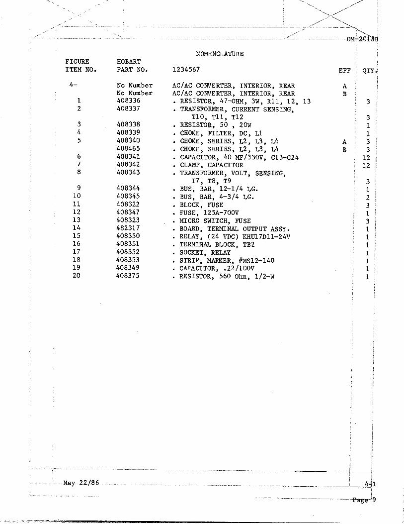
FIGURE HOBART ITEM NO. PART NO.
4-
1 2
No Number No Number 408336 408337
3 4 5
6 7 8
408338 408339 408340 408465 408341 408342 408343
9 408344 10 408345 11 408322 12 408347 13 408323 14 482317 15 408350 16 408351 17 408352 18 408353 19 408349 20 408375
NOMENCLATURE
1234567
AC/AC CONVERTER, INTERIOR, REAR AC/AC CONVERTER, INTERIOR, REAR . RESISTOR, 47-OHM, 3W, Rll, 12, 13 . TRANSFORMER, CURRENT SENSING,
TlO, Tll, T12 . RESISTOR, 50 , 20W . CHOKE, FILTER, DC, Ll . CHOKE, SERIES, L2, L3, L4 . CHOKE, SERIES, L2, L3, L4 . CAPACITOR, 40 MF/330V, C13-C24 . CLAMP, CAPACITOR . TRANSFORMER, VOLT, SENSING,
T7, T8, T9 . BUS, BAR, 12-l/4 LG. l BUS, BAR, 4-3/4 LG. . BLOCK, FUSE . FUSE, 125A-700V . MICRO SWITCH, FUSE . BOARD, TERMINAL OUTPUT ASSY. . RELAY, (24 VDC) KHUl7Dll-24V . TERMINAL BLOCK, TB2 . SOCKET, RELAY . STRIP, MARKER, #~S12-140 . CAPACITOR, .22/1OOV . RESISTOR, 560 Ohm, 1/2-w
: 3 ; 1 / 1
A/ 3 B/ 3
; 12 : 12

: .^
6 7 8
I
Control Panel Assembly Figure 5
i
E -r-
-
_.~. _ ~_-. May 22186: __ "__ _-. - - _c_--" .__.- _I-
i.- J!!ge .lO. I __.-.--i--_ _...... -_____ -___b

FIGURE HOBART ITEM NO. PART NO.
5- No Number CONTROL PANEL ASSEMBLY 1 408354 SWITCH, PUSHBUTTON, NO. SW-11 2 408355 . INDICATOR, LAMP, GR. DSl, DS2 3 408356 . SWITCH, START (Green) SW5 4 408357 . SWITCH, STOP (Red) SW6 5 408358 . INDICATOR, LAMP (Red) DS3 6 408359 . TERMINAL OUTPUT, (Black) TP-2 7 408360 . TERMINAL OUTPUT, (Red) TP-1 8 408361 . METER, OUTPUT VOLTAGE 0-150 VAC, Ml 9 408362 . SWITCH, VOLTAGE SELECTOR SW7
NOMENCLATURE
1234567 EFFi QT+
REF! 1 j
2: 1 ': 1: 1' 1;
P t

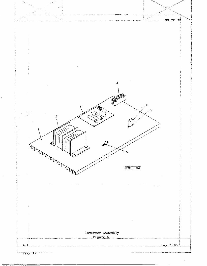
FIGURE HOBART ITEM NO. PART NO.
6- No Number INVERTER ASSEMBLY (For NHA See Fig. 2) 1 408363 . HEAT SINK 2 408364 . CHOKE, AIR-CORE ASSY. 3 408365~ . BOARD, SNUBBER ASSY. 4 408366 . POWER MODULE, 41-412 5 408367 . SWITCH, THERMAL, 105'C
"6 408368 . SENSOR, CURRENT, 70A, CSl-CS6 "7 408525 . RESISTOR, 2-OHM, 20-WATT 8 408518 . CAPACITOR, l-d?, l-KV 9 408517 . BRACKET, CAPACITOR
* NOT ILLUSTRATED
NOMENCLATURE
1234567 EFF) QTI
REI 6 6 6 2 1 6 6 6 6
9
7
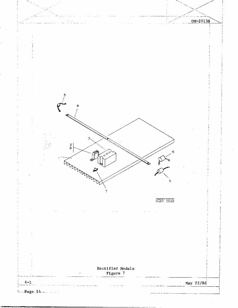
Rectifier Module Figure 7

FIGURE HOBART ITEM NO. PART NO.
7- No Number RECTIFIER MODULE (For NHA See Fig. 2) 1 408369 . HEAT SINK, REAR 2 408370 . CAPACITOR, .25/1OOOV, C9, 10, 11 3 408371 . RECTIFIER MODULE, CRl, 2, 3 4 408372 . BUS, BAR, 5/8 X l/8 X 17-13/16 LG. 5 408373 . MOV, VARISTOR, METALIZED 6 408374 . CAPACITOR, .l/lOOOV 7 408367 . SWITCH, THERMAL, 105'C 8 408376 . CLAMP, CAPACITOR 9 408346 . RESISTOR, 2-OHM, 3W,
.- -. ..^ _. .~ ‘-.-~--.---. .__.
May 22186 ~ ..- -.-. .~.._... ~._ _... _
I. I- . _- _ _ ._. _ _ ___
NOMENCLATURE
1234567 EFF QTY
REF 3 3 3 2 1' 1 1 3 1
~- f- !
I 4. -- ---J--,--
Page 1

- -
- cue. z
NlPIYCP
--
ITVtR
--
\ \ \
cl E -
RlYCR
-
1IYCR
zzz.cz
- -
PlYtR - -
P.C. Card Cage Assembly -... .-- ._.. FL.gum 8... __-. .-.._-_
h -. -6-l ._ _, -.. . .-_ --.--_~-22/_85;

FIGURE HOBART ITEM NO. PART NO.
8-
1 2 3 4 5 6 7 8
"9
408328 408466 408377K 408378K 408379H 4083803 408381L 408382~ 408383G 408384~ 408467
NOMENCLATURE
1234567 EFF QT
P.C. CARD CAGE ASSEMBLY A 1 P.C. CARD CAGE ASSEMBLY B 1 . BOARD, ALARM, I ASSEMBLY, Al 1 . BOARD, ALARM, II, ASSEMBLY, A2 1 . BOARD, OSCILLATOR, AMP ASSEMBLY, A3 1 . BOARD, COMPARATOR ASSEMBLY, A4 1 . BOARD, DRIVER, ASSEMBLY, A5-10 6 . BOARD, POWER SUPPLY II, All 1 . BOARD, POWER SUPPLY, 1, Al2 1 . BOARD, ALARM, III, ASSEMBLY, Al3 1 . BACK PLANE (MOTHER) BOARD ASSY 1
May 22186 L .- - - _.- _-.-- ..-. _ ._..
! ! I
I JE
I
p/ * I
1
I
!
i
I t

\ : % ._ , .” -’ -_ , .’ -\ ._ _ .,/’ ,’

FIGURE HOBART ITEM NO. PART NO.
9- 489403
1 2
3 4 5 6 7 8 9 10 11 12 13 14 15 16 17 18 19 20 21 22 23 24 25 26 27
28 29 30 31 32 33 34 35 36 37 38 39 40
* 41 42
* 43 * 44 * 45
84C-11OOA 84B-1099 408507 12Cw-2146 w-11563 w-11337-2 84B-1042 400562-40 81B-1062 DWP-982 488971 489278 489279 489273 488972 408394 408397 408387 408396 408398 408393 408388 408389 40839 1 408390 408399 408401 408400 408508 408402 408386 408395 408403 408410 408408 408413 408414 408407 408406
408405 408411 408412 408404 408415 408416 408417
NOMENCLATURE
1234567 EFF j
KIT, CONVERTER, TRAILER MTG. ASSY. (Optional) . TRAILER-CONVERTER . TIRE, 4:80 X 8 WHEEL ASSY. . AXLE, FRONT ASSY. . YOKE, THROTTLE ROD . PIN, CLEVIS CLARK . PIN, COTTER . CABLE, BRAKE ASSY. . SPRING, TENSION CABLE . LABEL, WARNING, DRAWBAR . BRACKET, CABLE . SUPPORT, BRAKE CABLE RT. l PLATE, END, REAR CONVERTER MTG. . PLATE, END, FRONT CONVERTER MTG. . FRAME, CONVERTER MTG. ASSY. . SUPPORT, BRAKE CABLE LT. . BOLT, 3/4-16 UNF X 5.00 . WASHER, FL 3/4" . SPINDLE, STEERING ARM ASSY, L.H. . BOLT, 3/4-16 UNF X 400 . NUT, SLOTTED 3/4" - 16 UNF . PIN, COTTER . DRAWBAR, TUBE ASSY. . GREASE, ZURK STRAIGHT . LATCH, TONGUE ASSY. . TONGUE, ASSY. . TIE ROD ASSY. LARGE . TIE ROD COUPLER ASSY. . TIE ROD ASSY., SMALL . AXLE, REAR ASSY. . GREASE, ZURK 90 . SPINDLE, STEERING ARM, ASSY. R.H. . BOLT, 3/4-16 UNF X 6.00 . HUBS, 5 ON 4-l/2 . GREASE, SEAL . OUTER, INNER, BEARING CONE . ELECTRIC BRAKE, RIGHT HAND 7" . ELECTRIC BRAKE, LEFT HAND 7" . HUB AND DRUM WITH CUPS . SPINDLE, WASHER
,
(DELETE) . SPINDLE, NUT . COVER, DUST . WHEEL, NUT . STUD, PRESS-IN l/2-20 X l-7/8 . COMPLETE BRAKE ASSY. LH. (Rear wheels) 1 . COMPLETE BRAKE ASSY. RH. (Rear wheels) I
. SECONDARY SHOE & LINING ASSY. (Rear Wheels)!
/
1 / !
1 / 4 1 2 2 ,:
2 I /
2 2 / l 1 4 1 1 1 1 1 2 8 j 1 1 4 4 1
/ ,
QTYi
.L i
> PRIM.Y SHOE & LINING ASSY. (Rear wheels) 1 >- . SPINDLE, NUT 1
I 2 --- - _-..--._ ! 4.

Mounting Brackets
Converter Unit (Front View)
UNIT WITH LONG
- MOUNTING BRACKETS
UNIT.WITH SHORT
MOUNTING BRACKETS
I Kit, Converter Bridge Mtg. Assy. (Optional) P
--- -- .TigtireIO~.- ----.----- -.~--.__-_ +.J I
1_ .._ !!--?..-.-- ._._- __ ._.. . - ~- . . --- . .._ _-- _ _ 1 May 22/84
L -Page. .2Q .- _. I _ -------.l-l-_.-.___p

NOMENCLATURE FIGURE HOBART ITEM NO. PART NO. 1234567 EFF
lo- 489404-l KIT, CONVERTER BRIDGE MTG. ASSY. (Narrow Mtg.)
489404-2 KIT, CONVERTER BRIDGE MTG. ASSY. (Wide Mtg.)
1 489381 . BRACKET ASSY, CONVERTER BRIDGE, NARROW-MOUNTING
2 489378 . BRACKET ASSY, CONVERTER BRIDGE, WIDE-MOUNTING
I
QTY. / / ! 1
j

Kit, Rain Shield Assembly (Optional) Figure 11
; 4-1' May 22186;
ii_ &.ge._2Z ._. . _------ ̂____.

NOMENCLATURE FIGURE HOBART ITEM NO. PART NO. 1234567 EFF ;
ll- 489395 KIT, RAIN SHIELD ASSY. (OPTIONAL) 1 489401 . GUARD, RAIN, FRONT AND REAR 2 489400 . GUARD, RAIN, SIDES 3 489396 . COVER, RAIN SHIELD, ASSY. 4 489402 . COVER, CONTROL PANEL
Qm
1 2 2 1 1

Forklift Mounting Assembly (Optional) _^

NOMENCLATURE FIGURE HOBART ITEM NO. PART NO. 1234567 EFF /
12- 489405 KIT, FOE LIFT MTG. AssY. (OPTIONAL) 1 1 489384 . FORK LIFT MTG. ASSY. 2
"2 w-11236-4 . SCREW, l/4-20 X l/2 HWH, SF-TAP, TYPE F ! 16
I
QTY

/ i
I
Kit, Converter Floor-Stand (Optional)
L -Pagel 2 @ . . . --_.---- I_- _.

-..
FIGURE HOBART ITEM NO. PART NO.
NOMENCLATURE
1234567 EFF j
13- 489448 KIT, FLOOR STAND, MTG. (OPTIONAL) 1 489449 . STAND, FLOOR, LEFT END ASSY. 2 489450 . STAND, FLOOR, RIGHT END ASSY. , 3 DWP-982 . BRACKET, CABLE
QTJ
I ,~.-__- --_ -- .--....... -- ---- .., .- --- .-.. _- -. ̂ .-.--._~ -...--._ --.--.--__-
ii I
".. . ._. ^... .- .- .._, --------"I-rage-rT

I
This page intentionally left blank.
,._ I . .- .“. --. ..-. -.-_. --.~...- - . . . .._ ~.. _ _.... .._~._ _._ --:
3.8
4-l : ._.__- -. May 22/86! ..--.. ..- .__......_ -._-.. Y-.-.-P
L-Xage-28-.- .. . __ . .._ - . . . --" ,___ _I_

UNUSUAL SERVICE CONDITIONS I
This information is a general guideline and cannot cover all possible j conditions of equipment use. The specific local environments may be dep$nden upon conditions beyond the manufacturer's control. The manufacturer should b# consulted if any unusual conditions of use exist which may affect the physica condition or operation of the equipment.
Among such conditions are:
1. Exposure to: I I
! /
t.
e/
l/ I
A.
B.
c.
D.
E.
F.
G.
H.
I.
J.
Combustible, explosive, abrasive or conducting dusts. I I
Environments where the accumulation of lint or excessive dirt wiil interfere with normal ventilation.
Chemical fumes, flammable or explosive gases.
Nuclear radiation. ! I
Steam, salt-laden air, or oil vapor.
Damp or very dry locations, radiant heat, vermin infestation, orj atmospheres conducive to fungus growth.
I Abnormal shock, vibration or mechanical loading from external sources during equipment operation.
Abnormal axial or side thrust imposed on rotating equipment shafts.
Low and/or high ambient temperatures.
High electromagnetic fields.
2. Operation at:
A. Voltages above or below rated voltage. B. Speeds other than rated speed. c. Frequency other than rated frequency. D. Standstill with rotating equipment windings energized. E. Unbalanced voltages. F. Operation at loads greater than rated.
3. Operation where low acoustical noise levels are required. I
4. Operation with: I
A. Improper fuel, lubricants or coolant. I B. Parts or elements unauthorized by the manufacturer. I
c. Unauthorized modifications. I