operation and maintenance manual - meyer … · operation and maintenance manual insist on genuine...
TRANSCRIPT

OPERATION and MAINTENANCE MANUALInsist on genuine Meyer Parts & Accessories
Snow, despite the beauty it may impart to a bleak winter landscape, poses the dual threat of inconvenience and danger. The environmental conditions associated with snow, not to mention the health hazards and economic loss it may impose, seriously endanger thousands of lives annually. Business and industry suffer, and millions of snowbelt residents may be affected by a single snowstorm.
Meyer Products Inc. has published this manual to help you get the maximum performance from your Meyer Snow Plow and familiarize you with the features designed for efficiency and safety; be sure you recognize and understand them. Follow recommended operation and maintenance instructions, so when a storm hits, your Meyer Snow Plow will be ready and you will know how to plow like a pro. DO NOT EQUIP ANY VEHICLE WITH A SNOW PLOW WITHOUT CONSULTING MANUFACTURERS’ RECOMMENDATIONS.
Vehicles with Meyer Snow Plows installed may be so equipped as to meet vehicle manufacturers’ specifications and recommended options for snow plowing use. Most vehicle manufacturers insist that vehicles which are to be used for snow plowing be equipped with certain
options and accessories, and it is so stated in vehicle manufacturer specifications for snow plow application.
Warning: Deployment of an air bag while using a Meyer snow plow will not be covered under Meyer Products’ warranty.We also recommended that, for optimum performance, vehicles used for snow plowing be equipped with: • Four Wheel Drive • Minimum 60 Amp Alternator or Larger • Minimum 70 Battery of Larger (550 C.C.A.) • Mud and Snow Tires • Increased Radiator Cooling • Automatic Transmission • Power Brakes • Power Steering
Under the continuing Meyer Products Improvement Plan, Meyer Products Inc. reserves the right to change design details and construction without prior notice and without incurring any obligation.
IMPORTANT NOTICE: In conjunction with FMVSS (Federal Motor Vehicle Standard) and OEM (Original Equipment Manufacturer) guide lines, Meyer Products LLC has designed this plow package with the following guidelines:
CAUTION: Installation of a snowplow may affect your vehicle warranty. For more information consult your Vehicle Owners’ Manual / Vehicle Dealer.
WARNING: The vehicle must not be operated when overloaded. In all cases, the loaded vehicle weight, including th entire snowplow system, all aftermarket acces-sories, driver, passenger, options, nominal fluid levels, and cargo must not exeed the front/rear Gross Axle Weight Rating (GAWR), and total Gross Vehicle Weight Rating (GVWR). These weight ratings are specified on the safetay compliance certification label on the driver’s side door opening. The use of rear ballast weight may be required to prevent exceeding the front GAWR.
WARNING: Check your local/state/provincial laws regarding vehicle restrictions when the snowplow is not attached. These restrictions during specified times of the year may require the removal of the mounting, lift frame, lift arm, hydraulic mechanism or any other fixtures or protruding surfaces mounted to the front of the vehicle.
Introduction

Table of Contents Page
Get to Know Your Meyer Xpress Snow Plow 2-3Xpress Specifications 4Snow Plow Controller Operation 5-6Removing & Attaching Your Meyer E-Z Mount Xpress™ 7General Maintenance & Adjustments 8-10E-68 Diagnosis Chart 11-13Efficient Snow Clearance Starts with Planning 14Keep Snow Under Control 14Selecting Proper Size Snow Plowing Equipment 15Hourly Snow Clearing Capacities 15Plow with the Storm 16Establishing Snow Clearance Plans 17Snow Plowing Tips from the Pros 18Snow Plowing in Open Areas 18Parking Lots and Wide Driveways 18-19Stacking Snow 20Trapped & Residential Areas 20Chemicals for Snow & Ice Control 21Meyer Products Salt Spreaders 21-23Meyer Accessories 24-27Genuine Meyer Parts 28-29Warranty Card Back Cover
www.meyerproducts.come-mail [email protected]
SAFETY FIRSTMeyer Products recommends that this manual be read cover to cover so that you are completely aware of all important safety recommendations. Record your E-68 Serial number and Moldboard Serial number. This number is printed on the decal under the hydraulic unit plastic cover.
-1-
Be sure to REGISTER your Snow Plow Sys-tem online at www.meyerproducts.com to
ensure maximum warranty protection.
Hydraulic Lift Serial Number _________________Moldboard Serial Number ___________________
THE INDUSTRY’S BEST WARRANTY PROTECTION
2 YEARS STANDARD ON ALL COMPONENTS
3 YEARS ON ALL COMPONENTS*
5 YEARS ON ALL STRUCTURAL STEEL* * Register at www.meyerproducts.com to activate years 3-5.

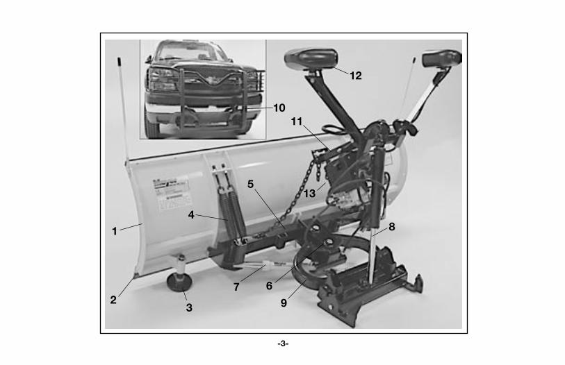
1. Aggressor™ Moldboard Made from 12 or 14 gauge steel, 6 vertical ribs. Painted with the
Meyer Sno-Flo® Powder Coat, that is a baked on finish that looks like glass, provides an extremely hard, low friction surface that outlasts ordinary paint by a large margin.
2. Cutting Edge Replaceable, high carbon steel provides extra long operating life;
should be 1/2” above ground in plowing position. (Can be higher when used on gravel driveways.)
3. Runners Mushroom replaceable runners hold cutting edge at proper height.
4. Trip Springs Allow moldboard to trip forward and ride over obstructions, this
protects the snowplow, vehicle, and operator.
5. Pivot Bar Positions moldboard straight across, angled right or left.
6. Pivot Pin Pin that attaches the moldboard to the pivot assembly.
7. Power Angling Cylinders Positions the moldboard hydraulically at all angles.
8. Mounting Cylinder Allows Plow Assembly to
be installed and removed in seconds.
9. Push Frame Allows the Snow Plow Push Frame attaching point to transfer the
power from the vehicle frame to the snow plow. Always keeps the plow level in any angled positions
10. Lift Frame Allows for fast, complete removal of snow plow, snow plow lights
and hydraulic unit in one complete module. Lift Frame will stay on the vehicle.
11. Lift Arm Chain locks in position to lift snow plow.
12. Meyer Snow Plow Lights Complies with the Federal Motor Vehicle Safety Standards.
13. E-68 Electric Hydraulic Power Unit Operates snow plow hydraulically—raises, lowers, angles, holds and
floats moldboard in plowing position. Mounts and Dismounts plow assembly from vehicle.
Get to know your Meyer® Snowplow
-2-
INSIST ON GENUINE MEYER PARTS & ACCESSORIES• Protect your warranty • Made to Meyer specifications • Fit right• Wear longer • Perform better • Your best value
-3-
32
14
5
679
1011
12
13
8

SPECIFICATIONS (AG/DAG-7.5) (AG/DAG-8.0) (AG/DAG-8.5) (AG/DAG-9.0)
WEIGHT (TOTAL) 850 lbs. 925 lbs. 945 lbs. 965 lbs.
HEIGHT 32” 32” 32” 32’
LENGTH 90” 96” 102” 108”
MOLDBOARD GAUGE #14 #12 #12 #12
VERTICAL RIBS 6 6 6 6
TRIP SPRINGS 4 4 4 4
CUTTING EDGES 3/8” X 6” 1/2” X 6” 1/2” X 6” 1/2” X 6”
PLOWING WIDTH
AT FULL ANGLE 78” 83” 88” 93”
POWER ANGLING RAMS 1-1/2” x 10”
-4-

SNOWPLOW HAND HELD CONTROLLER OPERATIONTo turn the controller on, press the on button located in the upper right hand corner on controller.
The snowplow should only be in operation when the vehicle ignition switch and the hand held controller are in the “ON” position. Care should be taken to insure that the hand held controller is kept dry and free from moisture during normal operation.
When the hand held controller is turned “On,” lights illuminate all buttons.
Lowering of the snowplow an inch at a time is possible by tapping the down arrow in short intervals. Holding down the down arrow for 1 second will activate a float light to the left of the on/off button. This light indicates the snowplow is now in the Lower/Float position. In this position the snowplow will be able to follow the contour of the road and the snowplow can also be angled to the left or right. Touching the up arrow automatically cancels the Lower/Float position.
Note: To regulate the lower speed, locate the Lower Adj. Screw on side of angling block. Loosen locking Nut Screw in to slow down or out for faster lower speed. See form 1-878 (E-68) for more details.
-5-
On
Right
Up
Left
Down
While angling left or right or raising the snowplow if the button is pressed for more than four seconds the operation will be cancelled. This feature eliminates unnecessary amp draw from the vehicle charging system.
The auto lower (ALM) button when pressed will illuminate the light above it and allows the plow to lower automatically when the vehicle is shifted into reverse and raise automatically when shifted out of reverse. To turn off the auto lower mode simply press the auto lower button again and the ALM light will go out.

-6-
The Shake (SHK) button when pressed will shake the plow left and right for three seconds. This function is used to shake off any snow which may be stuck to the plow. This function is only available within the last ten seconds of an angle, raise or lower operation.
Using the “Mount” buttonThe Mount (MNT) button when pressed will turn on the Mount/Dismount Mode. In this mode the Mount/Dismount Switch on the hydraulic unit is activated and no other snow plow functions will be available. To confirm that the Mount/Dismount switch is in the Mount/Dismount Mode all controller buttons will illuminate and flash. The buttons on the controller will continue to flash until the Mount (MNT) button is pressed again turning the Mount/Dismount mode off.
Activation of the Mount/Dismount Switch for longer than 15 seconds at a time will shut down the Mount/Dismount operation. Release of the toggle switch momentarily will allow activation to continue. This is an enhanced feature used in the Hand Held Controller for all snowplow functions. This feature eliminates unnecessary amp draw from the vehicle charging system when operating the snow plow.
Monitor LightThe Hand Held Controller is intelligent and will assist in diagnosing electrical problems. The Hand Held Controller continually monitors the snow plow system during plow
operation. When the Hand Held Controller recognizes a potential problem the Monitor Light will begin to flash. The Monitor Light is located in the upper left hand corner of the controller next to the Float indicator light.
Counting the number of flashes and using the diagnostic chart located on the back of the controller will help locate the component part that is causing the malfunction. See chart below.
See page 11-13 for more trouble shooting information.
The Hand Held Controller can be reset by the controller being turned off momentarily and then back on again.
Note: If Monitor light is still illuminated after attempts to reset the controller, please contact your nearest authorized Meyer Distributor for repairs.
Drop Adjustment
Top HoseMount Ram
Hose D.S. Ram(Right Angle)Bottom Hose
Mount Ram
Hose P.S. Ram(Left Angle)
"C" Green Wire (Right Angle)
"D"Yellow Wire (Left Angle)
Not Energized (Mount)
"E"Purple Wire (Dismount)
"B"Red Wire (Raise)
"A" Black Wire (Lower/Float)

Removing and Attaching Xpress PlowRemoving Xpress™ Assembly :1. Be sure Moldboard is on the ground.2. Remove Xpress Lock Pin (Figure 1).3. Turn on vehicle ignition switch, then Hand Held Controller.4. Press Mount (MNT) button on Hand Held Controller. All controller buttons will illuminate and flash.5. Activate system using the Mount/Dismount Switch in the direction that lowers the plow stand. Note: The Mount/Dismount Toggle Switch is located on the back side of the hydraulic unit (Figure 2). Continue lowering the plow stand until contact with ground is made and the hook assembly is raised up and off the Lift Frame. Note: While toggle switch is activated to keep assembly vertical, it will be necessary to use your other hand to lower the Lift Arm (completely) while at the same time the hook assembly is raising. See Figure 3. 6. It is also recommended that the Mount/Dismount cylinder be completely collapsed and the Xpress Lock Pin installed when system is removed from the vehicle to help prevent theft.7. Disconnect Main Harness from Lift Frame. See Figure 4.IMPORTANT: When Xpress TM system is removed from the vehicle, the Hand Held controller must remain “OFF” for proper operation of the OEM light system.
Mounting Xpress™ Assembly :1. Drive your vehicle up to the Xpress TM System until Lift Frame makes slight contact with Hook Assembly.2. Plug in Plow Side Harness into Vehicle Side Harness on Lift Frame making sure the harnesses lock together. See Figure 4 3. Turn on vehicle ignition switch, then Hand Held Controller.4. Press Mount (MNT) button on Hand Held Controller. All controller buttons will illuminate and flash.5. Activate system using the Mount/Dismount Switch in the direction that lowers the Hook Assembly onto the Lift Frame and raises the plow stand up to clamp and lock onto the bottom of the Lift Frame. Note: The Mount/Dismount Toggle Switch is located on the back side of the hydraulic unit (Figure 2).6. Install Xpress Lock Pin at the Plow Stand and Mount/Dismount Cylinder. See Figure 1.
Note: Under extreme circumstances the vehicle can generally be off 4 inches to either side of center line of the Hook Assembly. The system can still attach itself properly to the lift frame, however, extra care should be taken to insure the system is aligned and properly clamped onto the Lift Frame with Xpress Lock Pin installed.
WARNINGXpress Lock Pin Part NO. 07288 MUST be installed through the clevis stand u-clip and the mount ram tab when plow is attached to vehicle. This is a safety feature that insures the clevis stand stays attached to the Lift Frame at all times (See Mount Instructions and Figure 1).
-7-
Figure 1
Mount/Dismount switch
Figure 2
Figure 4Figure 3

General MaintenanceMeyer Products LLC recommends this maintenance information for regular service. Sustained heavy operation may call for more frequent service. Snow plowing subjects a vehicle to exceptionally rugged use. As a result, it is very important to inspect and bring the snow plow and vehicle up to maximum operating conditions. Inspection should be made of both the vehicle and snow plow prior to the plowing season and after each use.
Pre-season MaintenanceScheduled vehicle maintenance should be performed asrecommended by the manufacturer.
Don’t forget that in addition to keeping equipment in order:1. Keep windshield wipers, heaters and lights working.2. Use emergency flasher lights for increased visibility and safety.3. Equip vehicles with chains where necessary.4. Provide operators with protective clothing and with rubber gloves for handling snow melting chemicals.
VEHICLE ELECTRICAL SYSTEMFor maximum efficiency, the vehicle supporting the snow plow must be properly serviced. The system should consist of at least a 70 amp./hr. battery and a 60 amp alternator. Be sure to check regularly:1. Battery terminals to assure they’re clean and free of corrosion.2. Electrical connections, to assure they’re tight and corrosion free.3. Battery must be in top operating condition.4. Alternator and regulator, to assure maximum electrical output.
SNOWPLOWCAUTION: ALWAYS LOWER MOLDBOARD TO THE GROUND WHEN SNOW PLOW IS BEING SERVICED OR WHEN VEHICLE IS NOT IN USE.Check the E-68 Diagnosis chart, pages 12-13, and Post Season Maintenance, page 9, for advice on maintaining the unit.1. Check and maintain hydraulic fluid reservoir level to 1” from top cap. Oil level should be checked with lift ram and mounting cylinder on the Xpress in the down or retracted position.2. Check entire hydraulic system for leaks. A significant drop in hydraulic fluid level is evidence of a leak which must be corrected to prevent serious damage.3. Before and after each season, remove sector pivot pins, thoroughly grease pivot tubes and reinstall pins. Lubricate all pivot points with chassis lube.4. ADJUSTING TRIP SPRING TENSION FULL TRIP - Tighten top locknut 4 turns beyond the point when spring coils begin to separate. Tighten bottom locknut to hold eye bolt in position as shown in figure 1. DIAMOND EDGE- Tighten adjustment nut to the point when spring coils begin to separate.
Figure 1
-8-

5. RUNNERS A. Inspect moldboard runners for wear and height adjustment. B. Always replace runners as soon as they start to wear through. C. Adjust the runners to maintain cutting edge height of 1/2” above ground in snow plowing position. (Can be set higher when used on gravel driveways).6. CUTTING EDGEReplace the cutting edge as soon as it appears worn approximately 4” on either corner. This will prevent permanent damage to the moldboard.7. MOUNTING BOLTSRetighten all mounting bolts after first snow plowing session and at regular intervals through the season.8. DURA-SLICK™ POWDER COATING, both black and yellow, should be checked at the beginning and end of each season for any signs of rust. If any exists, use Meyer special Sno-Flo® powder coat touch-up available in spray cans.NOTE: PROTECTION AGAINST RUST AND CORROSION When the power unit is not used for extended periods, protect the chromed lift rod by fully extending and coating it with chassis lubricant. On power angling models, coat the exposed portions of the power angling cylinder rods with chassis lubricant to protect against corrosion.
Post Season Summer Maintenance 1. Draining & Replacing Meyer M-1 Hydraulic FluidTo drain mount cylinder (E-68 Only), fully extend and disconnect both hose fittings and allow cylinder to leak back down to the ground, draining it fully. Drain the fluid by removing the drain plug located on the front side of unit next to the motor. To drain the
fluid from the power angling cylinders, disconnect the fittings and completely retract the cylinder rods and purge cylinders and hoses of all hydraulic fluid. The complete system should then be flushed out with Meyer M-2 Flushing Fluid before adding new Meyer Hydraulic Fluid.
2. Screen-Type Filters- Clean the filters with mineral spirits orequivalent and blow out with compressed air.
3. Meyer M-1 Hydraulic Fluid is specially formulated with an anti-ice additive for almost constant viscosity in subzero temperatures. Because it is free-flowing in extreme cold, the unit’s performance and efficiency are not affected by winter weather. It is effective for a maximum of one year. Always carry an extra quart of Meyer M-1 Hydraulic Fluid. Use of any inferior fluids will void the Meyer warranty.
4. Refill power unit with Meyer M-1 Hydraulic Fluid by fullyretracting lift piston and mounting cylinder and filling reservoir to 1/2” below the filler hole. Note: Do not over fill unit, over filling unit will cause oil to squirt out of the reservoir pressure relief valve. Power angling rams should be collapsed. Install Hydraulic unit and Moldboard assembly on vehicle. Remove reservoir pressure relief valve (Filler plug) from top cap. To bleed air from the system power angle moldboard side to side while maintaining a constant check on the reservoir fluid level. Note: It may be necessary to bleed air from the Power angling cylinders by loosening the hydraulic fittings. Angle Moldboard side to side until you have a steady stream of oil coming out of fitting. Raise and lower the plow several times. With lift ram fully retracted (down) check fluid level and replace filler plug.-9-

SNOW PLOW STORAGE1. When snow plow is disconnected, extend lift cylinder to end of stroke and coat chrome rod with light grease. This fills the cylinder with hydraulic fluid and protects the interior and exterior from rust and corrosion.2. Whenever Moldboard is disconnected, coat the exposed portions of the power angling cylinder chrome rods with light grease to protect them from corrosion.3. Coat all pivot pins and other wear points with chassis lubricant. Be sure to grease all zerk fittings.4. Unplug electrical connection at power unit. Coat connection with a dielectric compound to prevent corrosion and plug into their corresponding weather plug.5. Reference past season summer maintenance on page 9 prior to final storage.
-10-

These charts are intended to be used as an aid in diagnosing problems on the E-68 Meyer Hydraulic Power Units. They are not a substitute for factory training and experience. Be certain to read the General Information and Testing Tips sections before attempting any troubleshooting. Additional detailed information as well as all electrical schematics may be found in Service Manuals 1-822.GENERAL INFORMATIONBefore any troubleshooting is started, make certain the following conditions are met.1. The moldboard is pointing straight ahead. This can often be done by coupling the hose from the left cylinder into the right cylinder
and pushing the snowplow by hand.2. The power angling cylinders must be installed correctly. The left cylinder has a hose with a female half of a coupler attached while the
right cylinder only has the male half of a coupler attached. Reverse them if installed on wrong side.3. Mount Cylinder top hose has female coupler; bottom is male.4. The electrical installation must have been made according to instructions supplied by Meyer Products LLC.TESTING TIPSMany tests do not require removing the Power Unit from the vehicle. However, more thorough testing can be done by using the Meyer Test Stand which allows direct pressure and Amperage readings.1. Use a screwdriver or other small tool to check for magnetism of solenoid coils (“A”, “B”, “C”, “D” & “E”). Place the tool on the nut securing the coil and have an assistant operate the switch. You should feel strong magnetic attraction.2. Use a test light or volt meter to determine whether there is power at harness or controller.3. When determining Amp draw of motor, always obtain the highest value possible, i.e., at maximum raise or angle with motor running.4. The pump shaft of a good pump can be turned smoothly using two fingers. If it can’t be turned easily, the pump must be replaced.6. Pump pressure can be measured at an angle hose (note pressure at full angle) or in the pressure filter port (an adapter is necessary for the filter port). (See Service Manual 1-822)7. If hydraulic system is contaminated it is recommended that the hydraulic unit, power angling rams and hoses be drained and flushed clean with M2 fluid. See page 24. The system should then be refilled with Meyer M-1 oil. See pages 9, 24.
DIAGNOSTIC TROUBLE SHOOTING
-11-

DIAGNOSTIC FLOW CHART FOR E-68 HYDRAULIC POWER UNITS MODEL CONDITION POSSIBLE CAUSE CORRECTION E-68 Plow does not lift or lifts 1. Low hydraulic fluid level. 1. Add fluid to proper level. slowly - motor operates. 2. Discharged battery. 2. Recharge battery. 3. Leaking or open “B” cartridge. 3. Clean or replace “B” cartridge. 4. No current to “B” coil. (Red wire) 4. Locate malfunction and repair. 5. Inoperative “B” coil. (Red wire) 5. Replace “B” coil. (Red wire) 6. Malfunctioning motor. 6. Repair or replace motor. 7. Malfunctioning pump. 7. Replace pump. Plow does not Angle Right 1. Improper coupler engagement. 1. Engage coupler properly. but Motor operates. 2. Mechanical bind or interference. 2. Eliminate mechanical bind or interference. 3. Malfunctioning coupler. 3. Repair or replace coupler 4. No current to “C” (Green Wire) coil. 4. Locate malfunction and repair. 5. Inoperative “C” (Green Wire) coil. 5. Replace coil. 6. Inoperative valve cartridge. 6. Clean or replace cartridge. 7. Leaking or open Pilot Check Valve 7. Clean or replace Pilot Check Valve 8. Leaking or open crossover relief valve. 8. Clean or replace crossover relief valve. Plow Does Not Angle Left 1. Improper coupler engagement. 1. Engage coupler properly. but Motor operates. 2. Mechanical bind or interference. 2. Eliminate mechanical bind or interference. 3. Malfunctioning coupler. 3. Repair or replace coupler, 4. No current to “D” (Yellow Wire) coil. 4. Locate malfunction and repair. 5. Inoperative “D” (Yellow Wire) coil. 5. Replace coil. 6. Inoperative valve cartridge. 6. Clean or replace cartridge. 7. Leaking or open Pilot Check Valve 7. Clean or replace Pilot Check Valve 8. Leaking or open crossover relief valve. 8. Clean or replace crossover relief valve. Plow will not hold in 1. Air in cylinders and hoses. 1. Bleed cylinders and hoses. Tighten P.A. angled position. cylinder gland nut. 2. Leaking “C” and or “D” cartridge O - rings. 2. Replace O - rings. 3. Defective “C” and or “D” valve cartridge 3. Replace cartridge. 4. Leaking Pilot Check Valve 4. Clean or replace Pilot Check Valve 5. Leaking crossover relief valve. 5. Clean or replace crossover relief valve 6. Crossover relief valve not set properly. 6. Replace/adjust crossover relief valve.E-88 Diagnosis Chart ®
-12-

DIAGNOSTIC FLOW CHART FOR E-68 HYDRAULIC POWER UNITS MODEL CONDITION POSSIBLE CAUSE CORRECTION E-68 Motor does not operate. 1. Discharged or defective battery. 1. Recharge or replace battery. 2. Loose or corroded electrical connections. 2. Clean and tighten electrical connections. 3. Inoperative starter solenoid. 3. Replace starter solenoid. 4 Malfunctioning control switch. 4. Replace control switch. 5. Malfunctioning motor. 5. Repair or replace motor Plow does not lower. 1. No current to “A” coil. (Black wire) 1. Locate malfunction and repair. 2. “A” cartridge jammed in closed position. 2. Clean or replace “A” cartridge. 3. Inoperative “A” coil. (Black wire) 3. Replace “A” coil. (Black wire) 4. Drop adjustment screw is turned all the way in. 4. Back out 1/2 turn Plow creeps down. 1. Leaking “A” cartridge. 1. Clean or replace “A” cartridge. 2. Leaking “A” cartridge O-ring. 2. Replace O-ring. 3. Leaking Ram Packing Cup. 3. Replace Ram Packing Cup. 4. Leaking O-ring at bottom of lift cylinder. 4. Replace O-ring, Xpress™ will not mount 1. Improper coupler engagement. 1 Engage coupler properly. motor operates 2. Mechanical bind or interference. 2. Eliminate mechanical bind or interference. 3. Malfunctioning coupler. 3. Repair or replace coupler 4. Jammed “E” (Purple Wire) cartridge. 4. Clean or replace “E” cartridge. 5. Leaking or open Pilot Check Valve 5. Clean or replace Pilot Check Valve Xpress™ will not 1. Improper coupler engagement. 1. Engage coupler properly. Dismount 2. Mechanical bind or interference. 2. Eliminate mechanical bind or interference. motor operates 3. Malfunctioning coupler. 3. Repair or replace coupler 4. No current to “E” (Purple Wire) coil. 4. Locate malfunction and repair. 5. Inoperative “E” (Purple Wire) coil. 5. Replace coil. 6. Jammed “E” (Purple Wire) cartridge. 6. Clean or replace “E” cartridge. 7. Leaking or open Pilot Check Valve 7. Clean or replace Pilot Check Valve
-13-
PREPARING AREAS, USE OF GUIDE MARKERSEvery area to be plowed should be inspected before snowfall for potential hazards. Holes should be repaired, raised manhole covers leveled or noted and obstructions noted to prevent damage to the plow mounting or vehicle undercarriage.
Markers or stakes with reflectors should be in position to indicate boundaries of areas to be plowed, location of shut-off valves, catch basins and other hazards. Markers should be at least three feet above the ground; higher in areas of deeper snowfall.
The first step in organizing an efficient plan is to prepare a map or procure a blueprint of the area. Locate and mark all utilities, outlets, shutoffs, catch basins and possible emergency equipment that must be reached from outside. Figure the square footage of each area and the total area. Especially note areas from which snow will have to be carried, call “trapped” areas. Although hauling is expensive, it is necessary where piled snow would limit access. Indicate clearing priorities on your map. This may aid you in preparing a priority plan for your clearance operation.
KEEP SNOW UNDER CONTROLDeep or heavy, wet snow, because of its increased weight, calls for more skillful and powerful plowing than light powder snow.
Efficient Snow Clearance Starts with PlanningAlways plow in low gear and keep plowing. Heavy snow may also require clearing a path or area for working room to move snow to another area. Remember that wet snow weighs about 12 pounds per cubic foot. As it piles up in front of a snow plow blade, the weight can quickly increase to several tons.
Where packed snow or ice must be plowed, it is sometimes necessary to lower the cutting blade to rest directly on the road surface. In that situation, plow in lowest gear for greatest power to the cutting edge. This method also prevents the plow from “climbing over” the icy surface.
If plowing very deep snow, 12 inches or more, you may have to plow with the blade partially raised to shear off successive layers of snow until a working area is clear. Then work small “bites” into the edge. The “bite” depth should be inversely proportional to the snow depth. A rule of thumb: 6-inch snow may be plowed with the entire blade width; 9-inch snow with 3/4 of the blade width; and 12-inch snow with only 1/2 of the width. Experience will show what work can be done without stalling or getting stuck.
-14-
Selecting EquipmentWhere you plan to plow, and the conditions under which you will be plowing, determine to a great extent the type of vehicle you’ll find most useful. In general, three types of vehicles are available as the power source of snow clearance. Each type has certain inherent advantages depending upon the particularsituation.
Four-wheel drive HEAVY DUTY TRUCKS have proven most effective in heavy duty snow plowing situations using the E-Z Mount Xpress™. They have excellent traction and the Xpress™ handles with ease.
Two-wheel drive TRUCKS, particularly those of 1 to 3 tons, arebest for straight line road clearance and in large open areas.
TRACTORS are effective for trapped areas in which visibility is limited, plus a rear grader blade can be used in conjunction with the Meyer Snowplow.
Meyer Snowplow’s custom design for specific vehicles provides the advantage of easy, fast attaching and detaching. This feature permits utilization of vehicle versatility as weather conditions and job requirements demand.
20 m.p.h. is a maximum snow plowing speed under ideal conditions, assuming the driver is familiar with the roadway or area to be cleared. Under unfamiliar or hazardous conditions, or if there is poor visibility, we recommend reduced speed andextreme caution.
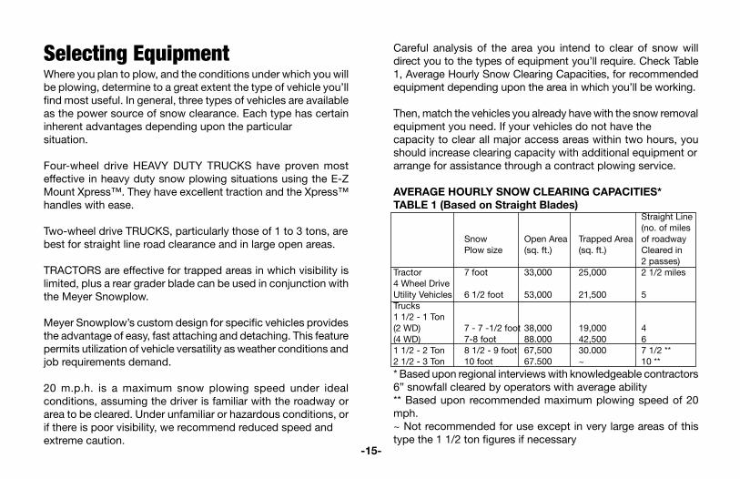
Careful analysis of the area you intend to clear of snow will direct you to the types of equipment you’ll require. Check Table 1, Average Hourly Snow Clearing Capacities, for recommended equipment depending upon the area in which you’ll be working.
Then, match the vehicles you already have with the snow removal equipment you need. If your vehicles do not have thecapacity to clear all major access areas within two hours, you should increase clearing capacity with additional equipment orarrange for assistance through a contract plowing service.
AVERAGE HOURLY SNOW CLEARING CAPACITIES*TABLE 1 (Based on Straight Blades) Straight Line (no. of miles Snow Open Area Trapped Area of roadway Plow size (sq. ft.) (sq. ft.) Cleared in 2 passes)Tractor 7 foot 33,000 25,000 2 1/2 miles4 Wheel DriveUtility Vehicles 6 1/2 foot 53,000 21,500 5Trucks 1 1/2 - 1 Ton(2 WD) 7 - 7 -1/2 foot 38,000 19,000 4(4 WD) 7-8 foot 88.000 42,500 61 1/2 - 2 Ton 8 1/2 - 9 foot 67,500 30.000 7 1/2 **2 1/2 - 3 Ton 10 foot 67.500 ~ 10 *** Based upon regional interviews with knowledgeable contractors 6” snowfall cleared by operators with average ability** Based upon recommended maximum plowing speed of 20 mph.~ Not recommended for use except in very large areas of this type the 1 1/2 ton figures if necessary
-15-

Plow with the StormIt is of utmost importance to remember one basic rule — Always plow with the storm. Start plowing when snow is 1 to 4 inches deep, depending upon traffic or other limitations. Heavy wet snow can be very hazardous when just 1 inch is on the ground. Accumulations of more than 4 inches can be very difficult to clear.
Plow with the Storm Angle Moldboard for Optimum Results. You will not be able to plow snow of any significant depth straight ahead for more than a short distance. Set the moldboard at the best angle for rolling snow sideways in the desired direction. The snow plow path, in the angled position, should exceed the tire track by at least six inches on either side. Be sure to have enough slack in the lift chain while plowing so the cutting edge of the moldboard can follow the ground contour. Use the adjustable runner shoes to set the bottom edge of the plow just above the ground for best operation.
It’s important to recognize the significance of even a few inches of snow. Besides being slippery, especially when wet, snow can be extraordinarily heavy, and make auto travel impossible. Snowfall of just 1 to 3 inches will produce hazardous traffic and roadway conditions even for experienced drivers.
Snow is heaviest when wet, and most difficult to handle. The National Weather Service reports that a 6-inch, average weight snowfall on a 200 x 200 foot parking lot weighs 62 tons. Heavy, wet snow for the same area might weigh as much as 248 tons. If the heavy snow had to be hauled away, you’d need 74 full loads on a l0-yard truck.
Obviously, the only way to assure clear traffic areas is to be prepared with the proper equipment and expertise to open arteries and areas to traffic. Remember to keep current with accurate snowfall information from local weather bureaus via radio and television.
-16-

These two snow plowing techniques have been time- and operation-tested. Use them as guidelines for most snow plowing strategies. Plan I is for smaller areas of 50,000 sq.ft. or less. Plan II is for larger establishments having more than 50,000 sq.ft. to be cleared.
PLAN I (less than 50,000 sq. ft.)
Recommended equipment: A four wheel drive vehicle; a ST-7 or ST-7.5 snow plow; snow shovels; and ice control equipment.
Recommended procedure: PLOW WITH THE STORM.
Begin plowing at the suggested accumulation for your type of establishment (i.e., 1” for commercial and institutional areas; 2” for industrial establishments; 3” for municipal and residential areas.) Continue until snow has been cleared. Don’t forget - snowfall often surpasses weather forecasts. A well planned clearing schedule will help prevent the necessity for expensive emergency action.
A typical small-area strategy:
1. Keep in touch with local weather forecasts for preparatory measures.
2. Notify scheduled personnel.
3. Have vehicles and equipment inspected, fueled and ready.
4. Clear area by pushing snow first to sides of drives, around perimeters of parking areas and away from loading docks and platforms. It is often true that the smaller the establishment, the greater the proportion of “trapped” areas which will require snow to be hauled away. Always deposit snow as far back as possible for greatest use of dumping areas.
5. Use snow shovels to clear walks, gates and doorways.6. Treat with snow-melting materials as needed.
PLAN II (over 50,000 sq.ft.)
Recommended equipment: The suggested number of vehicles, according to the Table “Average Hourly Snow Clearing Capacities”, on page 15, with ST-7 to HM-10 snow plows; front end loaders if needed; snow shovels and ice control equipment.
Recommended procedure: As always, PLOW WITH THE STORM. Begin plowing at the suggested accumulation for the area and continue as required. Actual snowfall frequently exceeds forecasted conditions. Well-planned snow clearance strategy reduces the chances for expensive emergency action.Snow Plowing Tips from the Pros
Two Established Snow Clearance Plans
-17-
SNOW PLOWING OPEN AREASOpen areas such as parking lots require a more serious approach to planning, where to begin, and where snow can be stacked at the edges. The following will help in making a plan, thus turning out a neat, professional job.
Always turn on warning flashers and/or use yellow warning beacon or strobe light when plowing. Then make a single pass down the center on the longest dimension. Angle plow the snow toward the long sides with continuous passes until the area is cleared and snow is all stacked around the outside edges.For larger areas, efficient plowing calls for clearing area immediately in front of buildings and working away from buildings toward the outer limits of the area. When snow is quite deep, it might be necessary to push the excess into piles out of main traffic lanes for later handling. Areas 100,000 sq.ft. or more — once the main artery is clear, it is usually most efficient to plow at right angles to the artery, piling up windrows by back and forth passes in alternate lanes. The windrows can later be pushed out of the way or left as is depending upon conditions.
To clean up remaining snow, you can put the blade in the straight position. Buck piles from either side to stack snow. The blade will automatically “ride” up the pile to make stacking easier.
On a dirt or slag surface, drop moldboard to ground in straight position, then raise one inch or adjust runners for desired clearance. Under extreme surface conditions it may be necessary to plow with moldboard in suspended position.
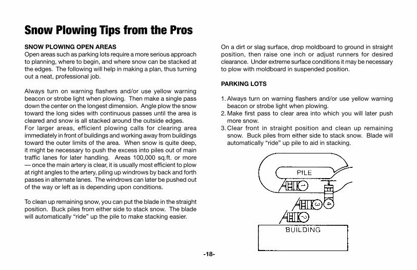
PARKING LOTS
1. Always turn on warning flashers and/or use yellow warning beacon or strobe light when plowing.
2. Make first pass to clear area into which you will later push more snow.
3. Clear front in straight position and clean up remaining snow. Buck piles from either side to stack snow. Blade will automatically “ride” up pile to aid in stacking.
Snow Plowing Tips from the Pros
-18-

STRAIGHT LINE SNOW PLOWINGThis method is most efficient for drives, streets, roads and walkways. Moldboard type blade snow plows mounted on utility vehicles or service trucks are best for such an operation.
Set the snow plow moldboard at an angle so that the snow is rolled to the shoulder or curb.
Single lane walks, roads and aisles can often be cleared with one pass.
When the road is more than twice the moldboard’s width, plow a center lane for the first full pass. Then, in follow-up passes, work the snow to the sides. The diagram illustrates plowing sequence for a typical 20-foot road.
Corner clearing is almost automatic when clearing intersecting streets. When snow is heavy, a little “stop over” snow may have to be removed from intersections by additional short passes.
We recommend a speed of 5 to 15 MPH for this kind of plowing. Of course, road surface, weather conditions and equipment will influence your speed.Plow with the storm.
BACK DRAGGING: WARNING: ST and C Series Only. Use caution when back
dragging. Runners can catch on objects causing damage to the equipment or the plowing surface. To reduce the risk of damage, remove or raise runners when back dragging.
WIDE DRIVEWAY
1. Make one pass down center with blade in straight position.
2. Push snow to side with moldboard angled.
3. Do the same on either side.
-19-

CLEARING TRAPPED AREASAreas where there is little or no space for stacking cleared snow are considered “trapped.” An example is an area requiring full access from surrounding buildings. Snow plowing techniques are the same as for any other space of comparable size, but heavy accumulations must be piled for removal by truck.
DRIVEWAYS
1. Plow toward garage pushing snow to one side.2. Set blade to straight position, lift it as high as possible and
drive through snow to garage. Drop blade and back drag to street.
3. Back into driveway and angle blade again. Use as many passes as necessary to clear drive.
CLEARING RESIDENTIAL AREAS
Driveways and aprons are most efficiently cleared by maneuverable four wheel drive vehicles. Recommended procedure is to enter the driveway rolling snow away from the residence. Stop about two-thirds of the way in, set the blade in bucking position, lift as high as possible, then drive through the snow to the garage. Drop the blade and back drag to the street. Turn around, back into the cleared path to the garage, reset the blade angle and continue rolling snow away from the house. Complete as many passes as necessary to clear the snow.
STACKING
When snow clearance conditions are perfect, snow can be merely pushed out of the way to unused areas. The first storm of the season, plow back from the drive area to allow space to pile future snowfall. It is usually necessary to pile snow up to considerable heights. In that case, push the snow forward and upward by raising the snow plow as you move into the pile. The vehicle’s momentum will carry the plow into the pile, avoiding equipment damage. The pile should slope outward, so later snows can be pushed upward. WARNING: Stacking snow or pushing up into high snow piles with the plow in Lower/Float or Angled position can cause damage to the Snow Plow components or the vehicle that will not be covered under the Meyer Products Warranty Program. Such damage may include, without limitation, twisting the A-Frame, the Moldboard hitting the Lift Arm, or the Plow Markers striking the vehicle.
-20-
RAISE SNOWPLOW BLADE WHEN STACKING SNOW

Meyer Spreaders
Hotshot ™(38100) &Hotshot HD™ (38110)The Meyer Hotshot spreaders promise to last season after season. These Spreaders are available in steel and stainless steel (HD). Both use a polypropylene hopper with a capacity to hold 1.3 c.f. / 70lbs. of salt, sand seed or any other free flowing material. Other features include; infinitely adjustable feed gate (up to 12 foot wide pattern), pneumatic tires and weather resistant fitted hopper covers which will keep the spreader material dry and contained in the hopper.
Mini Jr. (36006)The Meyer Mini Jr (5.75cu.ft.) is an ideal solution for small and medium sized jobs: walkways, intersections, access ramps and parking lots. The no rust thermoplastic hopper and internal vertical spiral auger provide continuos and even flow of material.Adjustable controls allow spreading of #1 rock salt from 3 to 30 feet. Easy to attach and detach. The Mini Jr. mounts to a standard 2” trailer receiver hitch.
Chemicals for Snow and IceExcept in very light snow, ice melting materials should never be used in place of snow plowing. However, in combination with trained personnel and equipment, ice melting materials play an important part in controlling ice and snow. Whenever possible, apply ice melting materials before a snowfall. You’ll use less, and it will be more effective in preventing snow and ice from adhearing to the pavement surface and less damaging for the environment. You may have to increase the use of ice melting materials at night and as temperatures fall.
Experts agree a mixture of two parts mixed ice melting materials (1:3 calcium chloride to salt, by weight) mixed with one part abrasive (cinder, sand or slag) is more effective than rock salt alone in melting snow and ice below 30°F. One hundred fifty pounds of such mixture with abrasives will treat a 50,000 sq.ft. surface.
It is imperative to treat priority areas such as hills, heavy traffic areas, bridges and intersections first, especially where snow may compact and adhere to the road surface, causing icy road condi-tions. When slush begins to stiffen and refreeze, it will be necessary to plow again and reapply chemicals.
-21-
Blaster Spreader350/350S750/750SThe BlasterTM Spreader is a poly tailgate spreader, available in four models that spread salt or salt & sand. What makes this spreader unique is its 1/2 horsepower direct drive motor, it’s the most powerful spreader motor available. The motor’s “Fast Blast” feature can produce up to 70 amps of surge power to grind through chunks of salt or sand. The 750- and 350-pound hoppers are made of extended life polyethylene and are backed by Meyer’s exclusive 3 + 5 year ROC Solid Warranty. Variable speed control allows for precise material spread pattern up to 40 feet.

Mate XL (38000)
The Meyer Mate XL spreader holds 9 cubic feet of salt, sand or calcium chloride and it can even spread seed to extend its use beyond the snow season. The Mate XL features a thermoplastic no-steel f rame for long- last ing protection from corrosion. The Mate XL is powered from a 1/6thH.P. 12VDC motor with in-cab variable speed control which will spread material up to 30’. A vibrator is standard on the XL model. The Mate XL requires NO drilling and is quickly attached and detached from any full size pick-up truck. Adjustable controls allow spreading of bagged#1 rock salt from 3 to 30 feet.
MDV Spreader 9’ Carbon Steel (63001) 9’ Stainless Steel (63004) 10’ Carbon Steel (63002) 10’ Stainless Steel (63005)The MDV spreader expands your choice between pickup size spreaders and the large V-box units. The MDV bridges the gap between the 15,000 GVW and the 20,000 GVW trucks. It can be powered by either your truck’s central hydraulic system or its own power source.
Replaceable Tailgate SpreaderT h i s r e p l a c e a b l e t a i l g a t e spreadermounts easi ly on most one-tondump bodies by s imply replacing theexisting tailgate. Designed to spreadfree-flowing chemicals, salt and/orsand throughout its entire width, thereplaceable tailgate spreader canspread in widths from 4’ to 40’. Ahost of optional equipment allowsyou to customize the spreader to fitmost any job requirement.
-22-
Under Tailgate SpreaderAn extremely rugged truck accessory, the Under-Tailgate Spreader is offered in two models: a single auger or for ultimate efficiency dual augers; each spreads cinders, sand, salt or pea gravel. Attaches easily under the tailgate of any standard dump truck, yet will not obstruct dumping over the spreader. The spinner is always in spreading position and can be operated with the truck moving backward or forward. Also available in stainless steel and direct drive.

Insert Hopper Spreaders1.8 cu. yd. Carbon Steel (62991),1.8 cu. yd. Stainless Steel (63006),2.0 cu. yd. Carbon Steel (62992),2.0 cu. yd. Stainles Steel (63007)The Meyer 1.8 & 2.0 cubic yard capacityV-box spreader for pickup trucks mountsand stores as a single unit. This mechanically-operated spreader is powered by an electric start 10 H.P. gas engine, which drives a high torque orbital-type motor and a 20:1 ratio gearbox. Spinner and drag chain speeds work in unison with engine R.P.M. The spinner will evenly spread material from four (4) to thirty (30) feet. In-cab controls make operation easy.
PolyHawkThis one-piece polyethylene hopper fits most 3/4 ton pickup truck beds and provides all the robust performance qualities of conventional V-box spreaders, but with less weight, greater capacity, longer life and less maintenance. The PolyHawk holds 37% more material than competitive poly spreaders. Another key feature of the PolyHawk™ is the swing-up spinner assembly. The swing up spinner allows for simplified clean-up and easy seasonal storage. The Poly Hawk is equipped with a top screen and a 16” wide stainless steel conveyor that provides reliable material handling control and has a replaceable stainless steel conveyor floor. Overlapping baffles, 2 internal and 4 external, and a 13” poly spinner disc provide precise material spreading. A 10 HP 4-cycle engine is standard and an 11 HP 4-cycle is available as an option.
STCCThe Tailgate Cross Conveyor (TCC) provides for the most efficient method of distributing granular materials available today. This sturdy cross conveyor will perform dozens of jobs while saving on labor, time and materials. Every municipality ,contractor, utility and construction company can benefit from the TCC cost efficient material handler. The cross conveyor transfers material left or right allowing for multiple uses. The TCC mounts directly to dump box with quick disconnect pins. Unit mounting allows for dumping over or parallel-to-ground positioning. Conveys most free flowing material.
-23-

M-1 Hydraulic FluidKeep your Meyer Electro-Touch® snow plow control system operating at peak performance; change hydraulic fluid yearly. Meyer M-1 Hydraulic Fluid has additives that insure peak efficient operation of all Meyer electric hydraulic power units (15134).
Hydra-Flush® Hydra-Flush™ advanced technology maintains your lift’s maximum performance by removing contaminants and performance robbing deposits. Hydra-Flush™ protects and preserves the life of your pump, seals, o-rings, and hoses. It is ideal for off-season storage (15901).
Sno•flo®Powder CoatTouch-Up PaintSuper-smooth high gloss paint especially formulated for use on powder coat finishes. Available in 12 oz. aerosol cans. Black (07026) Yellow (07027) & 1 qt. brush-on (07181).
Lock PinProtect your Meyer Snow Plow components with this sturdy, durable stainless steel and brass lock pin. Available in two sizes for the Quik-Lift or Electro-Touch power units and the EZ-Mount Xpress™. Quik-lift - 2” long (07694C) Electro-lift - 3” long (07695C)
Snow DeflectorAvailable in specific sizes to fit all Meyer moldboards. Kits come with attaching parts. Deflects snow flume down and away from windshield area. See page 26.
Rubber Cutting EdgeThe rubber cutting edge is reversible for extended wear life. Best results will be obtained with wet, unpacked snow. See page 25.
-24-
Meyer Accessories

Meyer® M1 Hydraulic FluidKeep your Meyer electric hydraulic control system operating at peak performance. It features special additives to ensure efficient operation.
Meyer® M2 Hydra-Flush™
Hydra-Flush contains a blend of additives that ensure maximum performance for flushing and off-season storage for all electric mechanical hydraulic units.
Genuine Parts KitsThe Genuine Parts Kit includes the most commonly requested Meyer parts. Everything comes pre-packaged in a sturdy tool kit.
Meyer® Heavy-Duty Molded Snow DeflectorDeflects snow flume down and away from your windshield. Available in specific sizes to fit all Meyer moldboards. Kits come ready to install. Patented.
Industrial Sno-Flo® PaintSpecially formulated to improve snow-rolling action. Aerosol spray available in Gloss Yellow, Gloss Black and White Primer. Gloss Yellow also available in 1-quart can.
-25-

Touch pad Leg StrapA perfect complement to the Touch Pad Controller, the leg strap keeps the Touch Pad close at hand. The adjustable buckle allows for a custom fit.
EZ-Mount Xpress Light GuardsOffered as an option with the EZ-Mount Xpress Mounting system only, the light guards give the front end of your 3/4 ton Ford, Chevy or Dodge pickup truck a sleek, stylish look.
Whelen Lights/AlarmsStand out and get noticed with warming lights, strobes and backup alarms from Whelen. These products are available in select styles and can easily be added to new or existing vehicles to increase your safety when plowing in congested or busy areas.
-26-
Rubber Cutting Edge (Full-trip)Produces excellent results on wet or unpacked snow. It’s reversible for extended wear.
Meyer® Diamond Edge Reversible Cutting Edge (Button-trip) The reversible cutting edge improves performance and durability. It also gives your plow an extra edge when cutting hard, packed snow and ice. Reversible to extend wear life.
-27-
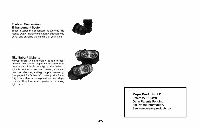
Timbren SuspensionEnhancement SystemTimber Suspension Enhancement Systems help reduce sway, improve roll stability, cushion road shock and enhance the handling of your 4 x 4.
Nite Saber® II LightsMeyer offers two snowplow light choices: Optional Nite Saber II lights are an upgrade to our standard Nite Saber I lights. Nite Saber II lights feature a four headlamp system, advanced complex reflectors, and high output harnessing. (see page 4 for further information). Nite Saber I lights are standard equipment on new Meyer mounts. They have a slim profile and a strong light output.
Meyer Products LLCPatent #7,114,270Other Patents PendingFor Patent Information,See www.meyerproducts.com

CUTTING EDGES - (STEEL) 8CE7.5 DAG-7.58CE8.0 DAG-8.08CE8.5 DAG-8.58CE9.0 DAG-9.0
CUTTING EDGE NUTS & BOLTS (STEEL) 08184 SET OF 9 AG-SERIES8CEBB DAG-7.5/DAG-8.0
DAG MOLDBOARD ASSY.811000003003 PIN 1-3/16 X 2-13/16”20420 COTTER PIN 1/4 X 2”09124 EYE BOLT W/LOCKNUT & CAP07017 TRIP SPRING84040 WEAR SHOE ASSY20361 FLATWASHER 1”811000224 5/16” LYNCH PIN
EZ MOUNT XPRESS® DIAMOND PAF81036 DIAMOND XP PIVOT BAR81037 DAG PLUS PUSH FRAME8511002008036 CHAIN 5/16 X 36” PLATED08852 PLOW MARKER KIT20420 COTTER PIN 1/4 X 2”22272 KING BOLT H 1-8 X 6-1/2 W/ GREASE FITTING22273 PIVOT BOLT H 1-8 X 6-1/222274 SLOTTED HEX NUT 1-88518001026 U-BOLT8501001007 HEX NUT 7/16-14
FAST MOVING PARTS LIST
-28-
RUBBER EDGES W/HARDWARE 08189 AG-7.508190 AG-8.008191 AG-8.508192 AG-9.0
SNOWPLOW HARDWARE 09124 EYE BOLT & NUTS07017 TRIP SPRING08852 MARKER KIT AG / DAG22375 PIVOT PIN W/GREASE FIT. 1 X 8-3/4” AG22331 HEAX HEAD PIN 1 x 3-5/16” AG
RUNNERS & SPINDLES 22083 LINCHPIN20363 WASHER AG20361 WASHER DAG20420 COTTER PIN 1/4” X 2”12449 RUNNER SPACER AG12394 MUSHROOM SHOE CASTING ASSY AG84040 WEAR SHOE ASSY DAG
A-FRAMES13735 XPRESS PUSH FRAME AG / DAG
PIVOT BARS / SECTORS 12360 PIVOT BAR AG81036 PIVOT BAR DAG
POWER ANGLING CYLINDERS 05877 1-1/2” X 10” SAE-6 ANGLE RAM05871 2-1/4” X 15” DA SAE-6 XPRESS MOUNTING RAM
ANGLING CYLINDER SEAL KITS 15964 SEAL KIT 1-1/2” X 10” SAE-6 ANGLE RAM15962 SEAL KIT 2-1/4” X 15” DA SAE-6 XPRESS MOUNTING RAM

-29-
HOSE & HOSE FITTINGS 22461 HOSE ASSY. 1/4 X 38” M-6 FACE SEAL22420 HOSE ASSY. 1/4 X 33” M-6 FACE SEAL
COUPLER’S HOSE END (OPTIONAL)22243 FEMALE COUPLER SAE-622244 MALE COUPLER SAE-6
SNOW DEFLECTOR KITS (POLYETHYLENE)FOR STEEL MOLDBOARDS12186 7.5 FT. LG. (AG-7.5)12040 8.0 FT. LG. (AG-8)12041 8.5 FT. LG. (AG-8.5)12042 9.0 FT. LG. (AG-9)
ELECTRIC/HYDRAULIC POWER15254 E-68 BASIC SEAL KIT15978 E-68 MASTER SEAL KIT
MISC. POWER UNIT 15727 MOTOR (ISKRA) TWO TERMINAL E-6815854 BRUSH KIT - ISKRA15889 PUMP ASSEMBLY E-6815980 BASE & STRAINER. ASSY E-68
E-68 POWER UNIT PARTS 15925 A & B SOLENOID ASSY. 15917 A & B VALVE CARTRIDGE 15926 C & D SOLENOID ASSY. 15918 C & D VALVE 15927 E SOLENOID ASSY. E-68 15919 E VALVE CARTRIDGE 15916 A, B, C, D & E COIL
CONTROLLER 22693 CONTROLLER
HARNESS 22694 PLOW SIDE 22691 TRIUCK SIDE
LIGHTS 07224 PLOW LIGHT - PASSENGER 07225 PLOW LIGHT - DRIVER
NOTE: ELECTRICAL REPLACEMENT PARTS LISTED ABOVE ARE FOR 12 VOLT SYSTEMS ONLY.
PAINT - TOUCH UP 07026 BLACK AEROSOL (1)08676 BLACK AEROSOL (12)07027 SNO-FLO AEROSOL (1) YE08677 SNO-FLO AEROSOL (12) YE07028 SNO-FLO BRUSH-ON .6 OZ. (1) YE08678 SNO-FLO BRUSH-ON .6 OZ.(12) YE07066 SNO-FLO - QT. (1) YE08686 SNO-FLO - QT. (12) YE
HYDRAULIC FLUID 15134 M-1 FLUID QUART15487 M-1 FLUID 12 QT. CASE
COUPLER’S HYDRAULIC SIDE (OPTIONAL)22242 MALE COUPLER SAE-622245 FEMALE COUPLER SAE-6
VISIT WWW.MEYERPRODUCTS.COMFOR MORE INFORMATION

Where Purchased
Company __________________________________________
City _______________________________________________
State ______________________________________________
Zip ________________________________________________
Date Purchased _________ / _________ / _______________ mm day year
Type of Store
Truck Equipment Distributor
Automotive Dealership
Power Equipment Store
Other ________________________
Thank you for buying the best built, best backed plow in the industry. In order to expedite customer service and warranty registration please complete the below information and have it ready to register your product on line at www.meyerproducts.com
Your Personal Plow Information
Vehicle Brand _________________________________________
Vehicle Model _________________________________________
Vehicle Year ___________________________________________
Vehicle Vin #
Hydraulic Serial #
Moldboard Serial #
www.meyerproducts.com

ME
YE
R®
/DIA
MO
ND
® S
NO
W P
LO
WS
LIM
ITE
D W
AR
RA
NT
Y E
FFE
CT
IVE
AU
GU
ST
1, 2
006
(Co
ntinued fro
m reverse sid
e)
What M
eye
r Pro
ducts W
ill Do:
Meyer P
roducts w
ill repair any p
roduct that p
roves to be d
efective in materials or w
orkmanship
. In the event rep
air is not possib
le or practical (as d
etermined
by M
eyer Prod
ucts in its sole discretion),
Meyer P
roducts w
ill either replace the p
roduct w
ith a new p
roduct of sim
ilar mod
el and p
rice, or refund
the full purchase p
rice, as determ
ined b
y Meyer P
roducts.
Custo
mer R
esp
onsib
ilities:
Custom
er must keep
the comp
lete Snow
Plow
Package serviced
/maintained
as recomm
ended
b
y Meyer P
roducts. A
written record
of service must b
e maintained
, along with receip
ts for m
aintenance materials p
urchased. A
copy of the m
aintenance record and
pertinent receip
ts may
be req
uested in the event of a claim
.
How
To G
et S
ervic
e:
In order to ob
tain service under this w
arranty, the original purchaser m
ust:•
Use all reasonab
le means to p
rotect the comp
lete snow p
low p
ackage from further d
amage;
• R
eturn the claimed
defective p
art to the Meyer®
/Diam
ond®
Distrib
utor/Sub
-Distrib
utor from
whom
the prod
uct was p
urchased or to any authorized
Meyer®
/Diam
ond®
Distrib
utor/Sub
-D
istributor, transp
ortation and freight charges p
repaid
. Only M
eyer®/D
iamond
® D
istributors/
Sub
-Distrib
utors are authorized to p
erform the ob
ligations under this w
arranty. For the add
ress and
telephone num
ber of the M
eyer®/D
iamond
® D
istributor/S
ub-D
istributor nearest you,
check the telephone d
irectory, go to ww
w.m
eyerprod
ucts.com
, write us at the ad
dress
below
, or call (216) 486-1313 for assistance;•
Provid
e maintenance record
and receip
ts for required
maintenance, if req
uested;
• A
llow insp
ection of dam
aged p
arts and/or com
plete snow
plow
package if d
eemed
necessary b
y Meyer P
roducts.
• It is the resp
onsibility of the original p
urchaser to establish the w
arranty period
by verifying the
original delivery d
ate. A b
ill of sale/sales receipt, cancelled
check or some other ap
prop
riate p
ayment record
may b
e kept for that p
urpose.
How
Sta
te L
aw
Applie
s:This w
arranty gives you specific legal rights, and
you may also have other rights w
hich vary from
state to state.
How
to re
giste
r you
r Meye
r/Dia
mond P
low
to re
ceive
the R
OC
Solid
Warra
nty
Go to w
ww
.meyerp
roducts.com
and click on the link to register your p
low.
Fill out the information on the form
as required
.The serial num
ber location of the m
oldb
oard is show
n in Figure 1.The serial num
ber location of the hyd
raulic unit is shown in Figure 2.
Fill out the remaind
er of the information to com
plete the registration.
ME
YE
R P
RO
DU
CTS
LLC18513 E
uclid Avenue • C
leveland, Ohio 44112-1084
ww
w.m
eyerproducts.com • e-m
ail info@m
eyerproducts.com
ME
YE
R®
/DIA
MO
ND
® S
NO
W P
LO
WS
LIM
ITE
D W
AR
RA
NT
Y E
FFE
CT
IVE
AU
GU
ST
1,
20
06
Wh
at
is C
ove
red
:M
eyer
Pro
duc
ts, L
LC, w
arra
nts
to t
he o
rigin
al p
urch
aser
of
Mey
er®
and
Dia
mon
d®
bra
nd p
rod
ucts
th
at t
hey
will
be
free
fro
m d
efec
ts in
mat
eria
ls o
r w
orkm
ansh
ip,
with
the
exc
eptio
ns s
tate
d b
elow
. N
o p
erso
n is
aut
horiz
ed t
o ch
ange
thi
s w
arra
nty
or t
o cr
eate
any
ad
diti
onal
war
rant
y on
Mey
er®
/D
iam
ond
® p
rod
ucts
.H
ow
Lon
g C
ove
rage L
ast
s:Th
is w
arra
nty
runs
for a
per
iod
of t
wo
year
s fr
om th
e d
ate
of p
urch
ase
on a
ny p
urch
ase
of a
com
ple
te
Sno
w P
low
Pac
kage
1 . If
the
Pac
kage
is r
egis
tere
d o
nlin
e at
ww
w.m
eyer
pro
du
cts.
com
with
in s
ixty
(6
0) d
ays
of p
urch
ase,
you
r w
arra
nty
for
the
Pac
kage
will
be
exte
nded
for
a p
erio
d o
f on
e ye
ar a
nd
you
will
als
o re
ceiv
e a
war
rant
y fo
r a
per
iod
of
five
year
s fr
om t
he d
ate
of p
urch
ase
on S
truc
tura
l S
teel
2 . In
ad
diti
on t
o th
e w
arra
ntie
s co
verin
g a
com
ple
te S
now
Plo
w P
acka
ge a
nd S
truc
tura
l Ste
el,
you
will
rec
eive
a w
arra
nty
for
a p
erio
d o
f on
e ye
ar f
rom
the
dat
e of
pur
chas
e on
ind
ivid
ual p
arts
, co
mp
onen
ts,
or a
cces
sorie
s. A
ll fo
rego
ing
war
rant
ies
app
ly o
nly
to a
n or
igin
al p
urch
aser
of
the
pro
duc
t if
the
pro
duc
t is
inst
alle
d b
y an
aut
horiz
ed D
istr
ibut
or/S
ub-D
istr
ibut
or a
nd t
erm
inat
e if
the
pro
duc
t is
sold
or o
ther
wis
e tr
ansf
erre
d. S
ome
stat
es d
o no
t allo
w li
mita
tions
on
how
long
an
imp
lied
w
arra
nty
last
s, s
o th
e ab
ove
limita
tion
may
not
ap
ply
to
you.
Wh
at
is N
ot
Cove
red
:Th
is w
arra
nty
doe
s no
t co
ver:
• P
rob
lem
s ca
used
by
failu
re t
o fo
llow
the
pro
duc
t in
stru
ctio
ns,
failu
re t
o m
aint
ain
the
pro
duc
t as
d
escr
ibed
in t
he O
per
ator
’s M
anua
l, or
failu
re t
o m
aint
ain
pro
per
leve
ls o
f lub
rican
ts;
• P
rob
lem
s ca
used
by
cont
amin
atio
n or
res
tric
tion
of lu
bric
ant
syst
ems,
or
dam
age
resu
lting
fro
m
rust
, cor
rosi
on, f
reez
ing
or o
verh
eatin
g;•
Pai
nt,
or e
xpen
dab
le s
now
plo
w p
arts
suc
h as
pin
s, r
unne
rs,
cutt
ing
edge
s, c
hrom
e p
latin
g,
sprin
gs a
nd m
arke
rs;
• D
amag
e to
any
veh
icle
to
whi
ch t
he p
rod
ucts
are
mou
nted
, or
the
sui
tab
ility
of
any
pro
duc
t fo
r ve
hicl
es w
hich
are
not
fitt
ed w
ith t
he a
pp
rop
riate
hea
vy-d
uty
snow
plo
w s
ervi
ce p
rep
arat
ion
par
ts;
• D
amag
e ca
used
by
usag
e th
at i
s no
t in
acc
ord
ance
with
pro
duc
t in
stru
ctio
ns (
use
of t
he s
now
p
low
for
any
pur
pos
e ot
her
than
plo
win
g sn
ow is
con
sid
ered
mis
use
and
ab
use)
;•
Any
sno
w p
low
, or
any
par
t, c
omp
onen
t, o
r as
sem
bly
the
reof
, w
hich
has
bee
n m
odifi
ed o
r al
tere
d;
• P
rob
lem
s ca
used
by
usin
g ac
cess
orie
s, p
arts
, or
com
pon
ents
not
sup
plie
d b
y M
eyer
Pro
duc
ts;
• C
ost
of t
ax, f
reig
ht, t
rans
por
tatio
n or
sto
rage
cha
rges
, env
ironm
enta
l cha
rges
, sol
vent
s, s
eala
nts,
lu
bric
ants
or
any
othe
r no
rmal
sho
p s
upp
lies.
• P
rob
lem
s ca
used
b
y co
llisi
on,
fire,
th
eft,
va
ndal
ism
, rio
t,
exp
losi
on,
light
ning
, ea
rthq
uake
, w
ind
stor
m, h
ail,
wat
er, fl
ood
, or
any
othe
r A
cts
of G
od;
• Li
abili
ty f
or d
amag
e to
pro
per
ty,
or in
jury
to,
or
dea
th o
f an
y p
erso
n ar
isin
g ou
t of
the
op
erat
ion,
m
aint
enan
ce o
r us
e of
the
cov
ered
pro
duc
t;•
Pro
duc
ts w
ith m
issi
ng o
r al
tere
d s
eria
l num
ber
s;
The
orig
inal
pur
chas
er’s
sol
e an
d e
xclu
sive
rem
edy
agai
nst
Mey
er P
rod
ucts
and
its
Dis
trib
utor
s an
d
Sub
-Dis
trib
utor
s, a
nd M
eyer
Pro
duc
ts’
sole
ob
ligat
ion
for
any
and
all
clai
ms,
whe
ther
for
bre
ach
of c
ontr
act,
war
rant
y, t
ort
(incl
udin
g ne
glig
ence
) or
oth
erw
ise
shal
l be
limite
d t
o p
rovi
din
g, t
hrou
gh
its
auth
oriz
ed
Dis
trib
utor
/Sub
-Dis
trib
utor
ne
twor
k,
all
lab
or
and
/or
par
ts
nece
ssar
y to
co
rrec
t su
ch d
efec
ts f
ree
of c
harg
e. A
ny c
ost
incu
rred
in
retu
rnin
g th
e p
rod
uct
to a
n au
thor
ized
Mey
er®
/D
iam
ond
® D
istr
ibut
or/S
ub-D
istr
ibut
or is
the
res
pon
sib
ility
of
the
orig
inal
pur
chas
er.
ALL
EX
PR
ES
S
AN
D
IMP
LIE
D
WA
RR
AN
TIE
S
FOR
TH
E
PR
OD
UC
T,
INC
LUD
ING
, W
ITH
OU
T LI
MIT
ATIO
N,
AN
Y
IMP
LIE
D W
AR
RA
NTI
ES
OF
ME
RC
HA
NTA
BIL
ITY
AN
D F
ITN
ES
S F
OR
A P
AR
TIC
ULA
R P
UR
PO
SE
, A
RE
LIM
ITE
D I
N T
IME
TO
TH
E T
ER
M O
F TH
E L
IMIT
ED
WA
RR
AN
TY P
ER
IOD
. N
O W
AR
RA
NTI
ES
, W
HE
THE
R E
XP
RE
SS
OR
IM
PLI
ED
, W
ILL
AP
PLY
AFT
ER
TH
E L
IMIT
ED
WA
RR
AN
TY P
ER
IOD
HA
S
EX
PIR
ED
. M
eyer
Pro
duc
ts d
iscl
aim
s lia
bili
ty b
eyon
d t
he r
emed
ies
pro
vid
ed f
or i
n th
is l
imite
d
war
rant
y, a
nd d
iscl
aim
s al
l lia
bili
ty f
or i
ncid
enta
l, co
nseq
uent
ial,
and
sp
ecia
l d
amag
es,
incl
udin
g,
with
out
limita
tion,
any
liab
ility
for
third
-par
ty c
laim
s ag
ains
t yo
u fo
r d
amag
es, f
or p
rod
ucts
not
bei
ng
avai
lab
le f
or u
se,
or f
or l
ost
pro
fits.
Mey
er P
rod
ucts
’ lia
bili
ty w
ill b
e no
mor
e th
an t
he a
mou
nt y
ou
pai
d f
or t
he p
rod
uct
that
is
the
sub
ject
of
a cl
aim
; th
is i
s th
e m
axim
um a
mou
nt f
or w
hich
we
are
resp
onsi
ble
. S
ome
stat
es d
o no
t al
low
the
exc
lusi
on o
r lim
itatio
n of
inc
iden
tal
or c
onse
que
ntia
l d
amag
es, s
o th
e ab
ove
limita
tion
or e
xclu
sion
may
not
ap
ply
to
you.
1 A c
omp
lete
Sno
w P
low
Pac
kage
con
sist
s of
the
hyd
raul
ic m
otor
, op
erat
ing
cont
rolle
r, lif
t-fr
ame,
m
old
boa
rd a
nd a
ll re
late
d it
ems.
2 Str
uctu
ral e
lem
ents
con
sist
of t
he m
ount
ing,
lift
-fra
me,
A-f
ram
e, s
ecto
r, an
d t
he m
old
boa
rd.
(Con
tin
ued
on
Rev
erse
Sid
e)
Form
No.
4-5
45R
3 04
08 6
C
Prin
ted
in th
e U
.S.A
. ©20
08