operation and maintenance manual - cerbos.ee fuse protection of the burner with the boiler: 6.3 a...
TRANSCRIPT
www.atmos.cz
Operation and
Maintenance Manual
Operation and Maintenance Manual - GB

www.atmos.cz
Operation and Maintenance Manual - GB
Operation and Maintenance Manual - GB
GB
www.atmos.cz GB-3
CONTENTS1. General information 4 Introduction 4 Application 4 Technical specifications 42. Design 5 Description 53. Burner accessories 94. Safety, burner installation and commissioning 10 Safety and connection of the burner to the boiler 10 Basic dimensions of the opening for installation of the burner in a boiler 115. Type of environment and location of the boiler with the burner in the boiler room 136. Chimneyn 137. Flue gas duct of the boiler 148. Fire protection within the installation and use of heat appliances 149. Basic connection diagram of a D30P, D31P, P31 a D45P boiler with an accumulation tank for burner control on the basis of TS and TV sensors 1610. Connection of boilers D30P, D31P, P31 a D45P with an accumulation tank for burner control on the basis of TS and TV sensors and control of the boiler pump on the basis of the TK sensor 1711. Connection of boilers D30P, D31P, P31 a D45P with an accumulation tank with solar heating for burner control on the basis of TS, TK and TV sensors (automatic sensor switching function), function of controlling the solar pump based on TSV and TS tempera 1812. Connection of boilers D30P, D31P, P31 a D45P with electronic regulation ACD01 and accumulation tank with solar heating 1913. Connection of boilers DCxxS, CxxS, ACxxS, KCxxS, DCxxRS with built-in burner in upper doors with accumulation tank for regulation of the burner based on sensors TS and TV and control of boiler pump based on TK sensor 2014. Connection of boilers DCxxS, CxxS, ACxxS, KCxxS, DCxxRS with built-in burner in upper doors and with ACD01 electronic regulation 2115. Connection of the boiler and burner to the electric mains 2216. Connection diagram of the electronic unit AC07X 2317. Electric diagram of the burner ATMOS A45 - 6-pin connector - model 2012 AC07X - (R, R2, sensors TV, TS, TK, TSV) 2418. Electric wiring diagram connection of the boilers D30P, D31P, P31 a D45P with extraction fan, model 2012 with 6-pin connector and module AD02 - to control extraction fan of the boiler from burner control unit AC07X (R) 2519. Electric wiring diagram connection of the boilers D30P, D31P, P31 a D45P with extraction fan, model 2012 with 6-pin connector and module AD03 - to control extraction fan of the boiler and pump in the boiler circuit from burner control unit AC07X (R and 2620. Electric wiring diagram connection of the boilers DCxxS(X), DCxxS, ACxxS, DCxxRS with extraction fan, model 2012 with 6-pin connector and module AD03 - to control extraction fan of the boiler and pump in the boiler circuit from burner control unit AC07 2721. Commissioning 2822. Control and setting of the burner 30 Display and control panel 30 Passwords and their functions 32 PARAMETERS menu 32 Setting the required power and combustion quality: 33 INFORMATION menu 49 TESTING menu 5023. Information - error messages - troubleshooting 51 General troubleshooting 51 Table of error messages on the display - alarms 51 If no problem has been found, reset the regulation AC07X by the RESTART command. 56 If the system is working, but you are not satisfied with its function, proceed as follows: 5624. Maintenance and cleaning of the burner 5725. List of spare parts 5926. Expanded view of the burner 60GUARANTEE TERMS 61RECORD OF INSTALLATION OF THE BOILER AND BURNER 62ANNUAL INSPECTIONS RECORDS 63RECORDS OF GUARANTEE PERIOD AND POST-GUARANTEE PERIOD REPAIRS 64
GB
www.atmos.cz4-GB
Operation and Maintenance Manual - GB
1. General informationWARNING - Before starting the burner you must get thoroughly acquainted with all provisions of this manual. The manufacturer is not liable for damages caused by operation, maintenance or wrong setting of the power of the burner that will cause heat overloading of the burner.
Introduction
This manual is intended for all users and contains information necessary for the installation, start-up, maintenance and safe operation of the burner. We recommend you to pay great attention to the safety regulations. Interventions that require removal of some parts should be carried out carefully by qualified authorized experts. Repairs andsettings that are not described in the manual should not be carried out at all.
Application
The burner is designed for ATMOS D30P, D31P, P31 and D45P special boilers.
Technical specifications
Name: ATMOS A45Prescribed fuel: high-quality (white) wooden pellets with the diameter of 6 to 8 mm, length of 5 to 25 mm and calorific value of 16 - 19 MJ.kg-1
Nominal heat input of the burner: 49 kWMinimum heat input of the burner: 8,5 kWMaximum heating surface of the boiler that the burner may be installed in: 5 m2 Fuel bin: not part of the delivery - recomended volume 1000 l Fuel feeding: with an external worm conveyor type DRA50, DA50 - not part of the delivery Burner control: with an AC07X (AC07) electronic control unit that controls the operation of the external conveyor, two ignition spirals and the fan in accordance with requirements of the boiler and the heating system. The electronic system is protected with the safety thermostat of the boiler, safety thermostat at the pellet supply to the burner, the fan speed transducer and the flame sensing photocell.The operation of the burner is indicated on the electronic control display. Power supply: 230 V / 50 Hz Maximum power input at the start with one ignition element: 480 W - normal settingMaximum power input at the start with two ignition elements: 1042 W - special functionsAverage power input at the nominal heat input operation: 47 WAverage power input at the minimum heat input operation: 29 W Average heat input in the standby mode: 3.3 WPrescribed fuse protection of the burner with the boiler: 6.3 AAcoustic pressure level (noisiness): 47 dBBurner weight: 23 kgBurner dimensions, WxHxD: 31 x 55 x 66 cmMinimum dimensions of the combustion chamber: diameter / width = 400 mm, length / depth = 400 mmMinimum ashpan space of the boiler: must correspond to operation at the nominal output for at least one week. (min. 4 l)Minimum vacuum in the combustion chamber of the boiler: 2 PaMin. protection against inadvertent opening of the boiler chamber (door): with a safety screw(except DxxP)
Operation and Maintenance Manual - GB
GB
www.atmos.cz GB-5
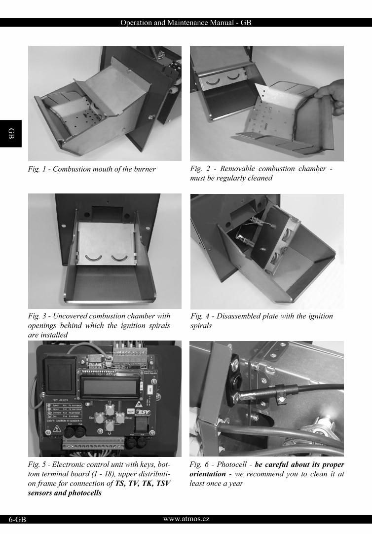
2. DesignDescription Heating with pellets with the use of the ATMOS A45 pellet burner has a lot in common with natural gas or oil heating. However, there is a difference that burning of pellets produces a certain quantity of ashes that must be removed from the burner and boiler in an interval to avoid impairment of efficiency or affecting thefunctionality of the burner. The ATMOS A45 pellet burner is supplied with automatic fuel ignition as standard. The assembly of the burner, external conveyor and fuel bin work completely automatically during operation and is controlled by an electronic control unit with the use of a flame sensor (photocell). In the burner body the fuel and combustionair are supplied in such a way to ensure maximum efficiency and environment-friendliness of fuel burning. Only high-quality pellets with the diameter of 6 to 8 mm and length of 5 to 25 mm should be fed into the burner. Pellets made of soft wood without bark, called white pellets, are considered as high quality pellets. Ashes are normally removed from the burner through the open door once every 7 to 30 days as necessary. It is recommended to thoroughly clean the inner parts of the burner once a year; for this operation the burner should be removed from the boiler. For ideal cleaning of the combustion chamber (pot) of the burner you can use a special vacuum cleaner or a poker.
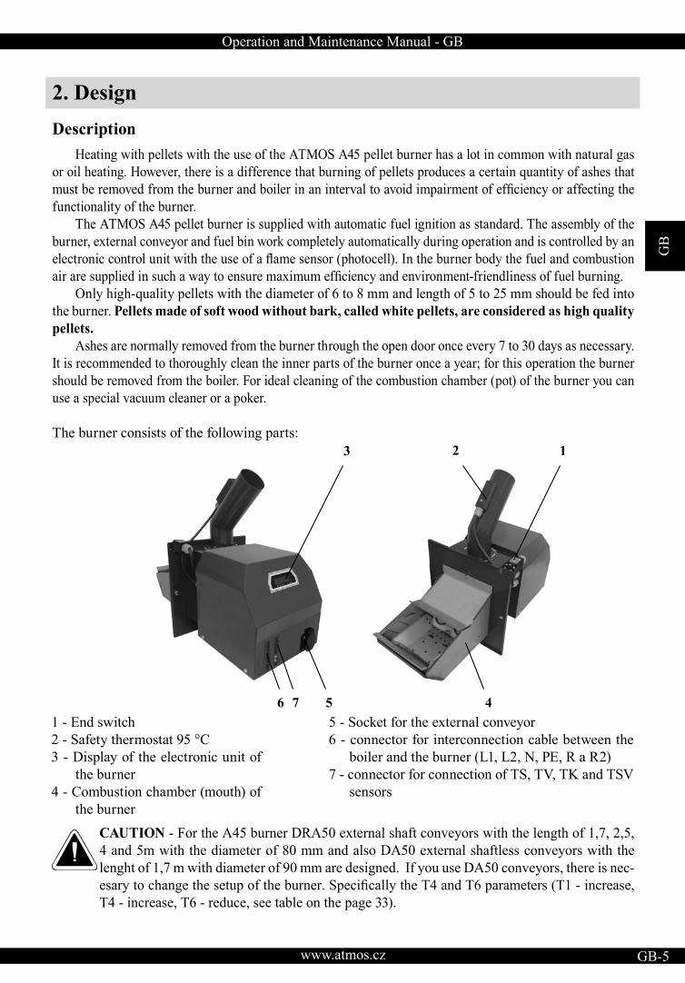
The burner consists of the following parts:
CAUTION - For the A45 burner DRA50 external shaft conveyors with the length of 1,7, 2,5, 4 and 5m with the diameter of 80 mm and also DA50 external shaftless conveyors with the lenght of 1,7 m with diameter of 90 mm are designed. If you use DA50 conveyors, there is nec-esary to change the setup of the burner. Specifically the T4 and T6 parameters (T1 - increase, T4 - increase, T6 - reduce, see table on the page 33).
1 - End switch2 - Safety thermostat 95 °C3 - Display of the electronic unit of
the burner4 - Combustion chamber (mouth) of
the burner
5 - Socket for the external conveyor6 - connector for interconnection cable between the
boiler and the burner (L1, L2, N, PE, R a R2)7 - connector for connection of TS, TV, TK and TSV
sensors
3
6 5
2
4
1
7
GB
www.atmos.cz6-GB
Operation and Maintenance Manual - GB
Fig. 4 - Disassembled plate with the ignition spirals
Fig. 2 - Removable combustion chamber - must be regularly cleaned
Fig. 3 - Uncovered combustion chamber with openings behind which the ignition spirals are installed
Fig. 6 - Photocell - be careful about its proper orientation - we recommend you to clean it at least once a year
Fig. 5 - Electronic control unit with keys, bot-tom terminal board (1 - 18), upper distributi-on frame for connection of TS, TV, TK, TSV sensors and photocells
Fig. 1 - Combustion mouth of the burner
Operation and Maintenance Manual - GB
GB
www.atmos.cz GB-7
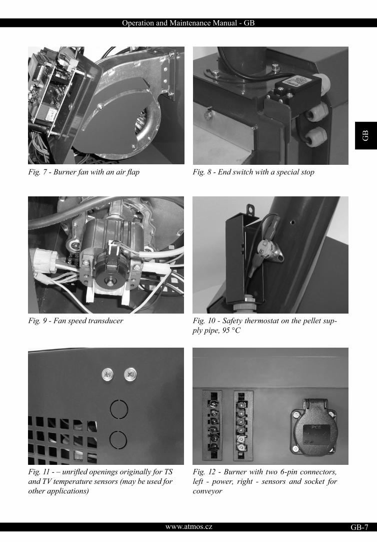
Fig. 7 - Burner fan with an air flap
Fig. 9 - Fan speed transducer
Fig. 8 - End switch with a special stop
Fig. 10 - Safety thermostat on the pellet sup-ply pipe, 95 °C
Fig. 11 - – unrifled openings originally for TSand TV temperature sensors (may be used for other applications)
Fig. 12 - Burner with two 6-pin connectors, left - power, right - sensors and socket for conveyor
GB
www.atmos.cz8-GB
Operation and Maintenance Manual - GB
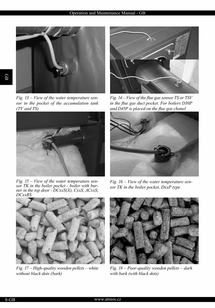
Fig. 13 – View of the water temperature sen-sor in the pocket of the accumulation tank (TV and TS)
Fig. 15 – View of the water temperature sen-sor TK in the boiler pocket - boiler with bur-ner in the top door - DCxxS(X), CxxS, ACxxS, DCxxRS
Fig. 14 – View of the flue gas sensor TS or TSV in the flue gas duct pocket. For boilers D30Pand D45P is placed on the flue gas chanel
Fig. 16 – View of the water temperature sen-sor TK in the boiler pocket, DxxP type
Fig. 17 – High-quality wooden pellets – white without black dots (bark)
Fig. 18 – Poor-quality wooden pellets – dark with bark (with black dots)
Operation and Maintenance Manual - GB
GB
www.atmos.cz GB-9
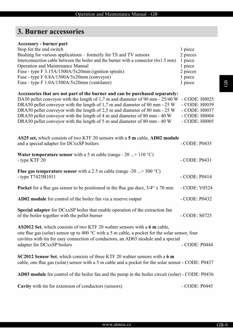
3. Burner accessoriesAccessory - burner partStop for the end switch 1 piece Bushing for various applications – formerly for TS and TV sensors 2 pieces Interconnection cable between the boiler and the burner with a connector (6x1.5 mm) 1 piece Operation and Maintenance Manual 1 piece Fuse - type F 3.15A/1500A/5x20mm (ignition spirals) 2 pieces Fuse - type F 0.8A/1500A/5x20mm (conveyor) 1 piece Fuse - type F 1.0A/1500A/5x20mm (ventilator) 1 piece
Accessories that are not part of the burner and can be purchased separately: DA50 pellet conveyor with the length of 1,7 m and diameter of 90 mm - 25/40 W - CODE: H0025DRA50 pellet conveyor with the length of 1,7 m and diameter of 80 mm - 25 W - CODE: H0039DRA50 pellet conveyor with the length of 2,5 m and diameter of 80 mm - 25 W - CODE: H0037DRA50 pellet conveyor with the length of 4 m and diameter of 80 mm - 40 W - CODE: H0004DRA50 pellet conveyor with the length of 5 m and diameter of 80 mm - 40 W - CODE: H0005
AS25 set, which consists of two KTF 20 sensors with a 5 m cable, AD02 module and a special adapter for DCxxSP boilers - CODE: P0435 Water temperature sensor with a 5 m cable (range - 20 ...+ 110 °C) - type KTF 20 - CODE: P0431 Flue gas temperature sensor with a 2.5 m cable (range -20 ...+ 300 °C) - type T7425B1011 - CODE: P0414
Pocket for a flue gas sensor to be positioned in the flue gas duct, 3/4“ x 70 mm - CODE: V0524 AD02 module for control of the boiler fan via a reserve output - CODE: P0432
Special adapter for DCxxSP boiler that enable operation of the extraction fan of the boiler together with the pellet burner - CODE: S0725
AS2012 Set, which consists of two KTF 20 wahter sensors with a 6 m cable, one flue gas (solar) sensor up to 400 °C with a 5 m cable, a pocket for the solar sensor, fourcavities with tin for easy connection of conductors, an AD03 module and a special adapter for DCxxSP boilers - CODE: P0444
SC2012 Sensor Set, which consists of three KTF 20 wahter sensors with a 6 m cable, one flue gas (solar) sensor with a 5 m cable and a pocket for the solar sensor - CODE: P0437
AD03 module for control of the boiler fan and the pump in the boiler circuit (solar) - CODE: P0436
Cavity with tin for extension of conductors (sensors) - CODE: P0445
GB
www.atmos.cz10-GB
Operation and Maintenance Manual - GB
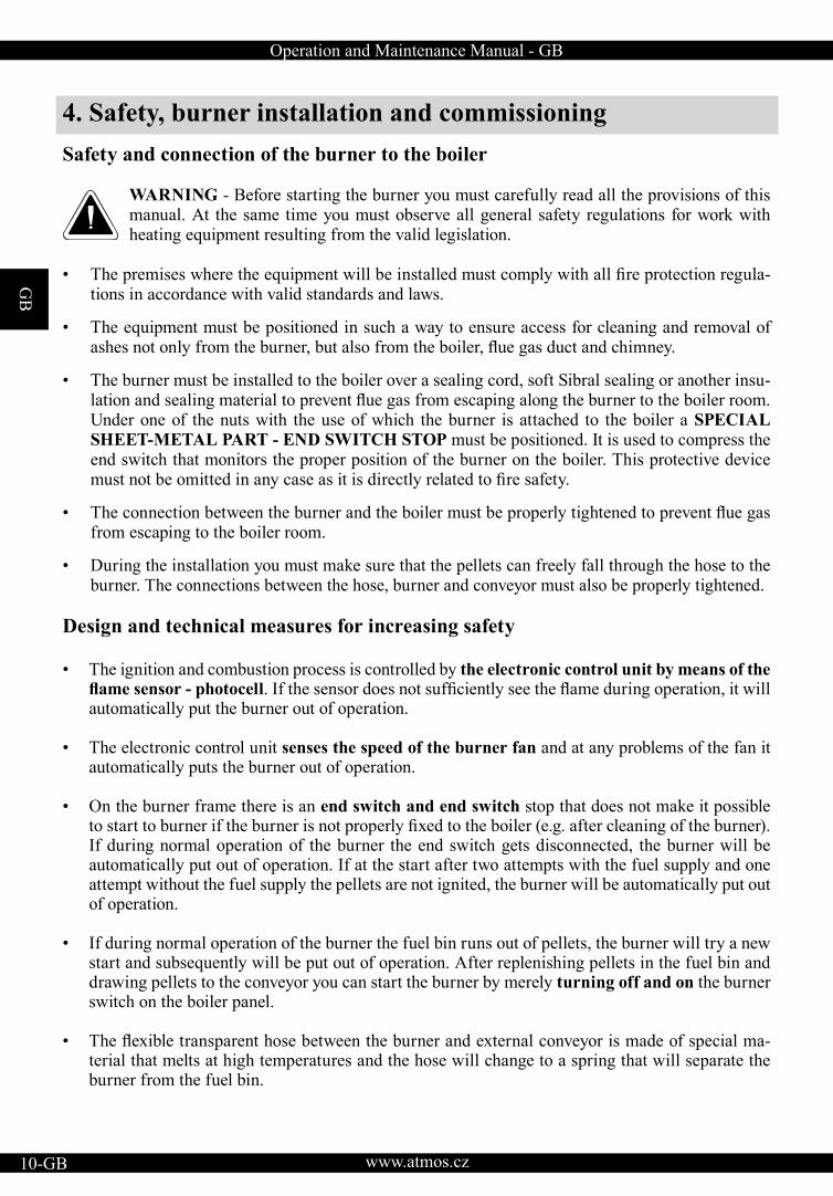
4. Safety, burner installation and commissioningSafety and connection of the burner to the boiler
WARNING - Before starting the burner you must carefully read all the provisions of this manual. At the same time you must observe all general safety regulations for work with heating equipment resulting from the valid legislation.
• The premises where the equipment will be installed must comply with all fire protection regula-tions in accordance with valid standards and laws.
• The equipment must be positioned in such a way to ensure access for cleaning and removal of ashes not only from the burner, but also from the boiler, flue gas duct and chimney.
• The burner must be installed to the boiler over a sealing cord, soft Sibral sealing or another insu-lation and sealing material to prevent flue gas from escaping along the burner to the boiler room.Under one of the nuts with the use of which the burner is attached to the boiler a SPECIAL SHEET-METAL PART - END SWITCH STOP must be positioned. It is used to compress the end switch that monitors the proper position of the burner on the boiler. This protective device must not be omitted in any case as it is directly related to fire safety.
• The connection between the burner and the boiler must be properly tightened to prevent flue gasfrom escaping to the boiler room.
• During the installation you must make sure that the pellets can freely fall through the hose to the burner. The connections between the hose, burner and conveyor must also be properly tightened.
Design and technical measures for increasing safety
• The ignition and combustion process is controlled by the electronic control unit by means of the flame sensor - photocell. If the sensor does not sufficiently see the flame during operation, it willautomatically put the burner out of operation.
• The electronic control unit senses the speed of the burner fan and at any problems of the fan it automatically puts the burner out of operation.
• On the burner frame there is an end switch and end switch stop that does not make it possible to start to burner if the burner is not properly fixed to the boiler (e.g. after cleaning of the burner).If during normal operation of the burner the end switch gets disconnected, the burner will be automatically put out of operation. If at the start after two attempts with the fuel supply and one attempt without the fuel supply the pellets are not ignited, the burner will be automatically put out of operation.
• If during normal operation of the burner the fuel bin runs out of pellets, the burner will try a new start and subsequently will be put out of operation. After replenishing pellets in the fuel bin and drawing pellets to the conveyor you can start the burner by merely turning off and on the burner switch on the boiler panel.
• The flexible transparent hose between the burner and external conveyor is made of special ma-terial that melts at high temperatures and the hose will change to a spring that will separate the burner from the fuel bin.
Operation and Maintenance Manual - GB
GB
www.atmos.cz GB-11
• The safety thermostat - located on the fuel supply pipe of the burner, will shut down the burner if its temperature is higher than 95 °C. Thus, it protects the burner from return ignition of pellets in the conveyor and at the same time from operation with clogged flue gas exhaust from the boiler(e.g. in case of a failure to remove dust from the boiler, flue gas duct and chimney). The safetythermostat will also put the burner out of operation in case the hose between the burner and con-veyor gets perforated to prevent flue gas from escaping to the boiler room.
INFO - After any shutdown of the burner when an error message (ALARM) appears on the display it is necessary to immediately find the cause and remove it. After removing thecause of the error you can start the burner by merely turning off and on the burner switch, which is located on the boiler panel.
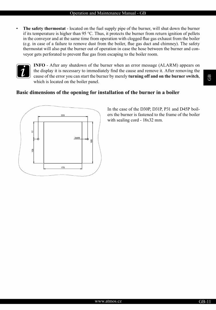
Basic dimensions of the opening for installation of the burner in a boiler
In the case of the D30P, D31P, P31 and D45P boil-ers the burner is fastened to the frame of the boiler with sealing cord - 18x32 mm.
GB
www.atmos.cz12-GB
Operation and Maintenance Manual - GB
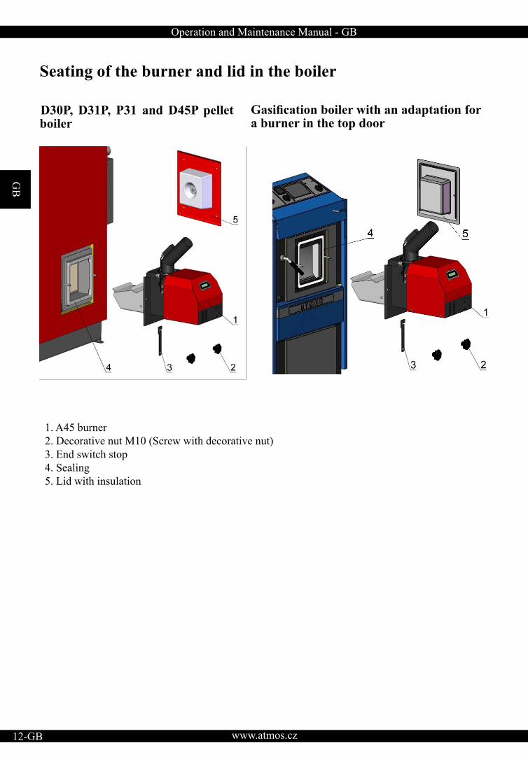
Seating of the burner and lid in the boiler
D30P, D31P, P31 and D45P pellet boiler
Gasification boiler with an adaptation fora burner in the top door
1. A45 burner 2. Decorative nut M10 (Screw with decorative nut)3. End switch stop4. Sealing 5. Lid with insulation
Operation and Maintenance Manual - GB
GB
www.atmos.cz GB-13
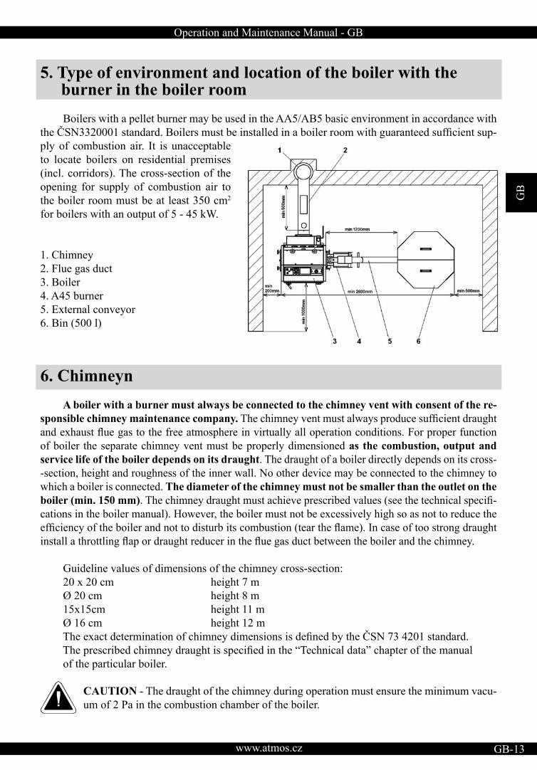
5. Type of environment and location of the boiler with the burner in the boiler room
Boilers with a pellet burner may be used in the AA5/AB5 basic environment in accordance with the ČSN3320001 standard. Boilers must be installed in a boiler room with guaranteed sufficient sup-ply of combustion air. It is unacceptable to locate boilers on residential premises (incl. corridors). The cross-section of the opening for supply of combustion air to the boiler room must be at least 350 cm2
for boilers with an output of 5 - 45 kW.
1. Chimney2. Flue gas duct 3. Boiler 4. A45 burner 5. External conveyor 6. Bin (500 l)
6. Chimneyn A boiler with a burner must always be connected to the chimney vent with consent of the re-sponsible chimney maintenance company. The chimney vent must always produce sufficient draughtand exhaust flue gas to the free atmosphere in virtually all operation conditions. For proper functionof boiler the separate chimney vent must be properly dimensioned as the combustion, output and service life of the boiler depends on its draught. The draught of a boiler directly depends on its cross--section, height and roughness of the inner wall. No other device may be connected to the chimney to which a boiler is connected. The diameter of the chimney must not be smaller than the outlet on the boiler (min. 150 mm). The chimney draught must achieve prescribed values (see the technical specifi-cations in the boiler manual). However, the boiler must not be excessively high so as not to reduce the efficiency of the boiler and not to disturb its combustion (tear the flame). In case of too strong draughtinstall a throttling flap or draught reducer in the flue gas duct between the boiler and the chimney.
Guideline values of dimensions of the chimney cross-section: 20 x 20 cm height 7 m Ø 20 cm height 8 m 15x15cm height 11 m Ø 16 cm height 12 m The exact determination of chimney dimensions is defined by the ČSN 73 4201 standard. The prescribed chimney draught is specified in the “Technical data” chapter of the manual of the particular boiler.
CAUTION - The draught of the chimney during operation must ensure the minimum vacu-um of 2 Pa in the combustion chamber of the boiler.
GB
www.atmos.cz14-GB
Operation and Maintenance Manual - GB
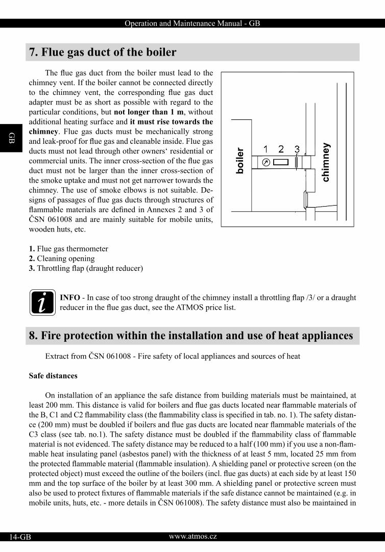
7. Flue gas duct of the boiler The flue gas duct from the boiler must lead to thechimney vent. If the boiler cannot be connected directly to the chimney vent, the corresponding flue gas ductadapter must be as short as possible with regard to the particular conditions, but not longer than 1 m, without additional heating surface and it must rise towards the chimney. Flue gas ducts must be mechanically strong and leak-proof for flue gas and cleanable inside. Flue gasducts must not lead through other owners‘ residential or commercial units. The inner cross-section of the flue gasduct must not be larger than the inner cross-section of the smoke uptake and must not get narrower towards the chimney. The use of smoke elbows is not suitable. De-signs of passages of flue gas ducts through structures offlammable materials are defined in Annexes 2 and 3 ofČSN 061008 and are mainly suitable for mobile units, wooden huts, etc.
1. Flue gas thermometer 2. Cleaning opening3. Throttling flap (draught reducer)
INFO - In case of too strong draught of the chimney install a throttling flap /3/ or a draughtreducer in the flue gas duct, see the ATMOS price list.
8. Fire protection within the installation and use of heat appliances
Extract from ČSN 061008 - Fire safety of local appliances and sources of heat
Safe distances
On installation of an appliance the safe distance from building materials must be maintained, at least 200 mm. This distance is valid for boilers and flue gas ducts located near flammable materials ofthe B, C1 and C2 flammability class (the flammability class is specified in tab. no. 1). The safety distan-ce (200 mm) must be doubled if boilers and flue gas ducts are located near flammable materials of theC3 class (see tab. no.1). The safety distance must be doubled if the flammability class of flammablematerial is not evidenced. The safety distance may be reduced to a half (100 mm) if you use a non-flam-mable heat insulating panel (asbestos panel) with the thickness of at least 5 mm, located 25 mm from the protected flammable material (flammable insulation). A shielding panel or protective screen (on theprotected object) must exceed the outline of the boilers (incl. flue gas ducts) at each side by at least 150mm and the top surface of the boiler by at least 300 mm. A shielding panel or protective screen must also be used to protect fixtures of flammable materials if the safe distance cannot be maintained (e.g. inmobile units, huts, etc. - more details in ČSN 061008). The safety distance must also be maintained in
Operation and Maintenance Manual - GB
GB
www.atmos.cz GB-15
case of installation of fixtures near boilers. If boilers are located on a floor of flammable materials, they must be installed on a non-flammable,heat-insulating pad, exceeding the ground plan at the side of the feeding and ashpan opening by at least 300 mm before the opening - at the other sides by at least 100 mm. As non-flammable, heat insulationpads you can use all materials of the A flammability class.
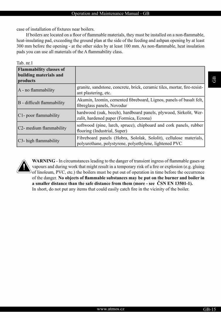
Tab. nr.1Flammability classes of building materials and products
A - no flammability granite, sandstone, concrete, brick, ceramic tiles, mortar, fire-resist-ant plastering, etc.
B - difficult flammability Akumin, Izomin, cemented fibreboard, Lignos, panels of basalt felt,fibreglass panels, Novodur
C1- poor flammability hardwood (oak, beech), hardboard panels, plywood, Sirkolit, Wer-zalit, hardened paper (Formica, Ecrona)
C2- medium flammability softwood (pine, larch, spruce), chipboard and cork panels, rubber flooring (Industrial, Super)
C3- high flammability Fibreboard panels (Hobra, Sololak, Sololit), cellulose materials, polyurethane, polystyrene, polyethylene, lightened PVC
WARNING - In circumstances leading to the danger of transient ingress of flammable gases orvapours and during work that might result in a temporary risk of a fire or explosion (e.g. gluingof linoleum, PVC, etc.) the boilers must be put out of operation in time before the occurrence of the danger. No objects of flammable substances may be put on the burner and boiler ina smaller distance than the safe distance from them (more - see ČSN EN 13501-1).In short, do not put any items that could easily catch fire in the vicinity of the boiler.
GB
www.atmos.cz16-GB
Operation and Maintenance Manual - GB
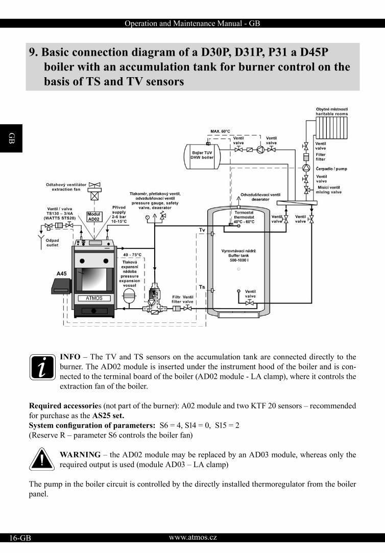
9. Basic connection diagram of a D30P, D31P, P31 a D45P boiler with an accumulation tank for burner control on the basis of TS and TV sensors
INFO – The TV and TS sensors on the accumulation tank are connected directly to the burner. The AD02 module is inserted under the instrument hood of the boiler and is con-nected to the terminal board of the boiler (AD02 module - LA clamp), where it controls the extraction fan of the boiler.
Required accessories (not part of the burner): A02 module and two KTF 20 sensors – recommended for purchase as the AS25 set.System configuration of parameters: S6 = 4, S14 = 0, S15 = 2(Reserve R – parameter S6 controls the boiler fan)
WARNING – the AD02 module may be replaced by an AD03 module, whereas only the required output is used (module AD03 – LA clamp)
The pump in the boiler circuit is controlled by the directly installed thermoregulator from the boiler panel.
A45
Operation and Maintenance Manual - GB
GB
www.atmos.cz GB-17
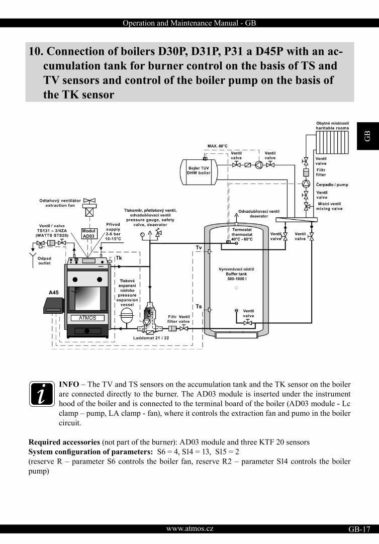
10. Connection of boilers D30P, D31P, P31 a D45P with an ac-cumulation tank for burner control on the basis of TS and TV sensors and control of the boiler pump on the basis of the TK sensor
INFO – The TV and TS sensors on the accumulation tank and the TK sensor on the boiler are connected directly to the burner. The AD03 module is inserted under the instrument hood of the boiler and is connected to the terminal board of the boiler (AD03 module - Lc clamp – pump, LA clamp - fan), where it controls the extraction fan and pumo in the boiler circuit.
Required accessories (not part of the burner): AD03 module and three KTF 20 sensorsSystem configuration of parameters: S6 = 4, S14 = 13, S15 = 2(reserve R – parameter S6 controls the boiler fan, reserve R2 – parameter S14 controls the boiler pump)
A45
GB
www.atmos.cz18-GB
Operation and Maintenance Manual - GB
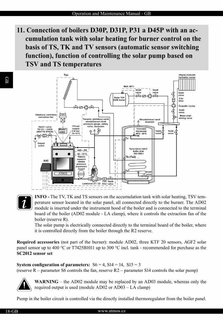
11. Connection of boilers D30P, D31P, P31 a D45P with an ac-cumulation tank with solar heating for burner control on the basis of TS, TK and TV sensors (automatic sensor switching function), function of controlling the solar pump based on TSV and TS temperatures
INFO - The TV, TK and TS sensors on the accumulation tank with solar heating, TSV tem-perature sensor located in the solar panel, all connected directly to the burner. The AD02 module is inserted under the instrument hood of the boiler and is connected to the terminal board of the boiler (AD02 module - LA clamp), where it controls the extraction fan of the boiler (reserve R).The solar pump is electrically connected directly to the terminal board of the boiler, where it is controlled directly from the boiler through the R2 reserve.
Required accessories (not part of the burner): module AD02, three KTF 20 sensors, AGF2 solar panel sensor up to 400 °C or T7425B1011 up to 300 °C incl. tank - recommended for purchase as the SC2012 sensor set
System configuration of parameters: S6 = 4, S14 = 14, S15 = 3(reserve R – parameter S6 controls the fan, reserve R2 – parameter S14 controls the solar pump)
WARNING – the AD02 module may be replaced by an AD03 module, whereas only the required output is used (module AD02 or AD03 – LA clamp)
Pump in the boiler circuit is controlled via the directly installed thermoregulator from the boiler panel.
Operation and Maintenance Manual - GB
GB
www.atmos.cz GB-19
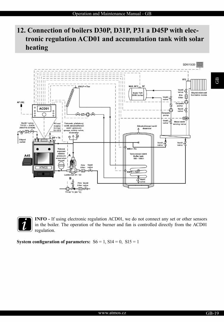
12. Connection of boilers D30P, D31P, P31 a D45P with elec-tronic regulation ACD01 and accumulation tank with solar heating
INFO - If using electronic regulation ACD01, we do not connect any set or other sensors in the boiler. The operation of the burner and fan is controlled directly from the ACD01 regulation.
System configuration of parameters: S6 = 1, S14 = 0, S15 = 1
A45
GB
www.atmos.cz20-GB
Operation and Maintenance Manual - GB
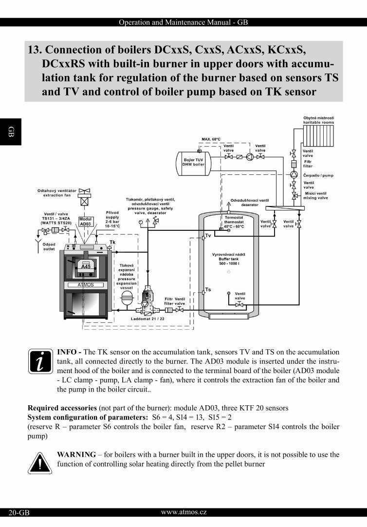
13. Connection of boilers DCxxS, CxxS, ACxxS, KCxxS, DCxxRS with built-in burner in upper doors with accumu-lation tank for regulation of the burner based on sensors TS and TV and control of boiler pump based on TK sensor
INFO - The TK sensor on the accumulation tank, sensors TV and TS on the accumulation tank, all connected directly to the burner. The AD03 module is inserted under the instru-ment hood of the boiler and is connected to the terminal board of the boiler (AD03 module - LC clamp - pump, LA clamp - fan), where it controls the extraction fan of the boiler and the pump in the boiler circuit..
Required accessories (not part of the burner): module AD03, three KTF 20 sensorsSystem configuration of parameters: S6 = 4, S14 = 13, S15 = 2(reserve R – parameter S6 controls the boiler fan, reserve R2 – parameter S14 controls the boiler pump)
WARNING – for boilers with a burner built in the upper doors, it is not possible to use the function of controlling solar heating directly from the pellet burner
A45

Operation and Maintenance Manual - GB
GB
www.atmos.cz GB-21
14. Connection of boilers DCxxS, CxxS, ACxxS, KCxxS, DCxxRS with built-in burner in upper doors and with ACD01 electronic regulation
INFO - If using electronic regulation ACD01, we do not connect any set or other sensors in the boiler. The operation of the burner, solar and fan is controlled directly from the ACD01 regulation.
System configuration of parameters: S6 = 1, S14 = 0, S15 = 1
Side view
A45A45
GB
www.atmos.cz22-GB
Operation and Maintenance Manual - GB
15. Connection of the boiler and burner to the electric mains Only connect the burner to the 230 V, 50 Hz electric mains via the boiler with a mains cable without a plug so that the conductors (L, N) should not be interchanged. The mains supply must be replaced with the same type by a repair organization. The boiler must be positioned in such a way that the connector on the burner can be within the operator’s reach (in accordance with ČSN EN 60335-1).
CAUTION - Boilers with a burner may only be connected by a qualified person in accord-ance with all the relevant valid regulations of the particular country while great attention must be paid to safe earthing of the boiler. After the installation of the burner on the boiler the technician must connect the burner and subsequently the entire boiler to the electric mains in accordance with the attached wiring diagram (page 24).
Connection:
Between the burner and boiler a six-wire cable is newly used that is connected with one end to the burner with a 6-pin connector (part of the burner) and the other end with a 6-pin connector to the boiler.
The meaning of the conductors is as follows:
• Black – phase L1 (230V, 50Hz) – With the main switch of the boiler on the black conductor is per-manently live (independently of the control thermostat of the boiler). It is the supply voltage of the burner. This phase must be fuse protected via the safety thermostat of the boiler (95 - 110 °C).
• Brown – phase L2 (230V, 50Hz) – The brown conductor is controlled by the control or another thermostat on the boiler panel. It brings the phase, impulse for the burner start. It is perceived as the starting (ignition) and shutdown signal. This phase must also be fuse protected via the safety thermostat of the boiler. (95 – 110 °C).
• Grey - reserve R (L3) (230V/50Hz) - The grey conductor is connected to the free place on the boiler terminal board in the case of the boiler version with the 4-pin connector or directly to the 5-pin connector on the boiler. It serves as a reserve conductor for various functions of the boiler, characterized with the S6 parameter. If you do not use the reserve function, connect the supply cable directly to the connector, not connecting or cutting off the grey cable
• Red - reserve R2 (230V/50Hz) – the red conductor is connected directly to the 6-pin connector on the boiler. It serves as the second free reserve for various functions of the boiler, characterized with the S14 parameter. If you do not use the reserve function, do not connect or cut off the red cable.
• Blue - N – Neutral – The blue conductor is connected to the neutral conductor.
• Yellow and green - PE – Protective Earthing – The yellow and green conductor is connected to the earth.
Operation and Maintenance Manual - GB
GB
www.atmos.cz GB-23
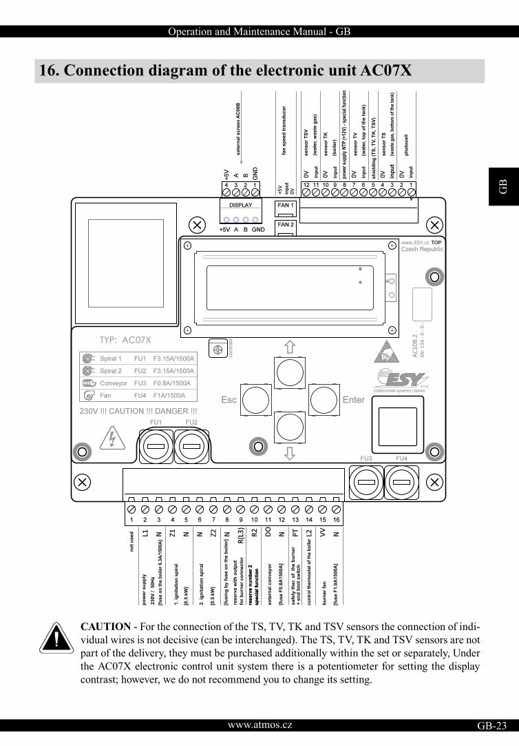
16. Connection diagram of the electronic unit AC07X
CAUTION - For the connection of the TS, TV, TK and TSV sensors the connection of indi-vidual wires is not decisive (can be interchanged). The TS, TV, TK and TSV sensors are not part of the delivery, they must be purchased additionally within the set or separately, Under the AC07X electronic control unit system there is a potentiometer for setting the display contrast; however, we do not recommend you to change its setting.
ex
tern
al
sc
ree
n A
C0
6B
fan
sp
ee
d t
ran
sd
uc
er
se
ns
or
TS
V
(wa
ter,
wa
ste
ga
s)
inp
ut
inp
ut
inp
ut
inp
ut
inp
ut
se
ns
or
TK
(bo
ile
r)
se
ns
or
TV
se
ns
or
TS
ph
oto
ce
ll
pow
er s
uppl
y N
TP (+
12V
) - s
peci
al fu
nctio
n
(wa
ter,
to
p o
f th
e t
an
k)
(, b
ott
om
of
the
tan
k)w
aste
gas
inp
ut
no
t u
se
d
po
we
r s
up
ply
23
0V
/
50
Hz
2.
ign
ita
tio
n s
pir
al
[0.5
kW
]
1.
ign
ita
tio
n s
pir
al
[0.5
kW
]
[fu
se
on
th
e b
oil
er
6.3
A/1
50
0A
]
sh
ield
ing
(T
S,
TV
, T
K,
TS
V)
[fu
sin
g b
y f
us
e o
n t
he
bo
ile
r]
res
erv
e w
ith
ou
tpu
t
for
bu
rne
r c
on
ne
cto
r
res
erv
e n
um
be
r 2
sp
ec
ial
fun
cti
on
ex
tern
al
co
nv
ey
or
[fu
se
F0
.8A
15
00
A]
res
erv
e n
um
be
r 2
sp
ec
ial
fun
cti
on
sa
fety
th
er.
of
th
e b
urn
er
+ e
nd
lim
it s
wit
ch
co
ntr
ol th
erm
osta
t o
f th
e b
oiler
bu
rne
r fa
n
[fu
se
F1
.0A
15
00
A]

GB
www.atmos.cz24-GB
Operation and Maintenance Manual - GB
17. Electric diagram of the burner ATMOS A45 - 6-pin con-nector - model 2012 AC07X - (R, R2, sensors TV, TS, TK, TSV)
L1
N
L N
L2
R
230V / 50Hz R T
°C
TV TS
TK
TSV
GN
D
GN
D
GN
D
GN
D
NTPFAN1
FAN2
TV
TS
TSV
TK
R2
GND
GNDTSTVTK
TSV
R2
11_06_01 - A25/45_AC07X

Operation and Maintenance Manual - GB
GB
www.atmos.cz GB-25
18. Electric wiring diagram connection of the boilers D30P, D31P, P31 a D45P with extraction fan, model 2012 with 6-pin connector and module AD02 - to control extraction fan of the boiler from burner control unit AC07X (R)
1 2 3 4 5 6 7 8 9 10 11 12
M M
M
R R2
poj-C
poj-1
FUS
E 6
,3 A
SIC
HE
RU
NG
6,3
AP
OJI
STK
A 6
,3 A
HLv
yp
SN
vyp
HN
vyp
SLv
yp
1 24 5
t°C
PE
T-C
T-2
T-1
t°C
PE
PT-
1
PT-
C
L
N
230V/50Hz
A
a+
b-R2
B
D
C
F
E
L N
G
H
L
N
A
B
C
D
E
F
H
G
I
vyp2
-1
vyp2
-4
vyp2
-2
vyp2
-5
1 2 4 5
t°C BT-
L2
BT-
L1
BT-
N1
BT-
N2
L
N
L
NR
LAN
LB
I
L2
L1
N
RR2
A25-45 6PINKONEKTOR
KONDENZATOR 1 Fµ
GB
www.atmos.cz26-GB
Operation and Maintenance Manual - GB
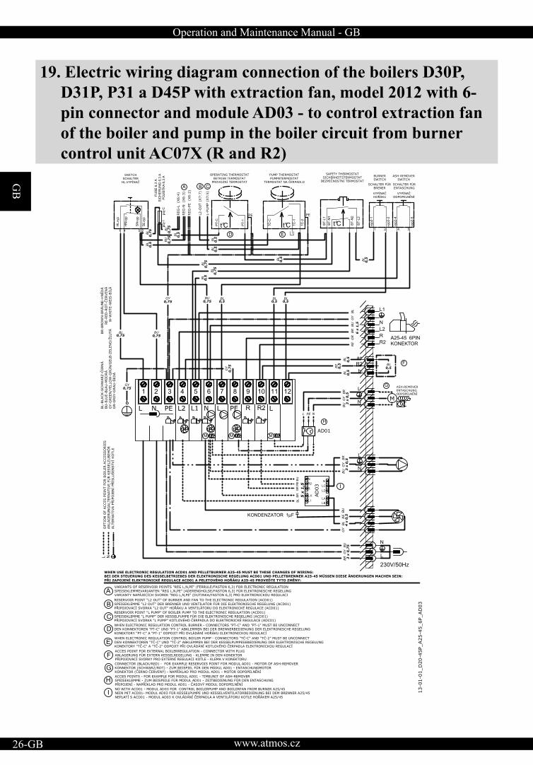
19. Electric wiring diagram connection of the boilers D30P, D31P, P31 a D45P with extraction fan, model 2012 with 6-pin connector and module AD03 - to control extraction fan of the boiler and pump in the boiler circuit from burner control unit AC07X (R and R2)
1 2 3 4 5 6 7 8 9 10 11 12
M M
M
R R2
poj-C
poj-1
FUS
E 6
,3 A
SIC
HE
RU
NG
6,3
AP
OJI
STK
A 6
,3 A
HLv
yp
SN
vyp
HN
vyp
SLv
yp
1 24 5
t°C
PE
T-C
T-2
T-1
t°C
PE
PT-
1
PT-
C
L
N
230V/50Hz
A
a+
b-R2
B
D
C
F
E
L N
G
H
A
B
C
D
E
F
H
G
I
vyp2
-1
vyp2
-4
vyp2
-2
vyp2
-5
1 2 4 5
t°C BT-
L2
BT-
L1
BT-
N1
BT-
N2
I
L
N
L I
N
R
LA
N
LB
L II
R2LCLD
BL
BU
GR
BR
RE
L
N
L2
L1
N
RR2
A25-45 6PINKONEKTOR
KONDENZATOR 1 Fµ
Operation and Maintenance Manual - GB
GB
www.atmos.cz GB-27
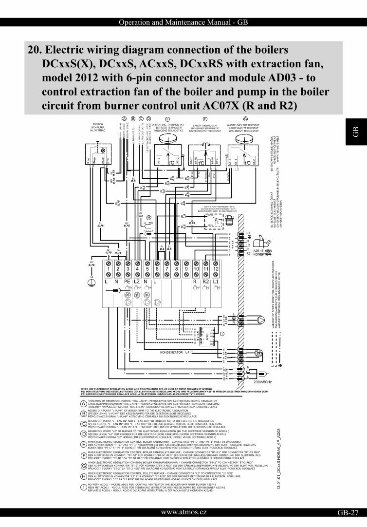
20. Electric wiring diagram connection of the boilers DCxxS(X), DCxxS, ACxxS, DCxxRS with extraction fan, model 2012 with 6-pin connector and module AD03 - to control extraction fan of the boiler and pump in the boiler circuit from burner control unit AC07X (R and R2)
13-0
1-01
_DC
xxS
HO
RAK
_6P_
AD
03
1 2 3 4 5 6 7 8 9 10 11 12
t
A
A
HLv
yp
SNvy
p
HN
vyp
SLvy
p
1 24 5
C DB
I
B
C
D
E
H
F
BT-N
1 R
EG
L N
BT-L
2
BT-
N2
BT-
N1
BT-
L1
G
ST-2
REG
G
H
E F
I
L
N
AD03
L I
N
R
LA
N
LB
L II
R2LCLD
BLBU
GR
BRR
E
t°C
t°CBT-L
2
BT-L
1
BT-N
1
BT-N
2
t°C
L
N
230V/50Hz
L2
L1
N
RR2
A25-45 6PINKONEKTOR
KONDENZATOR 1 Fµ
GB
www.atmos.cz28-GB
Operation and Maintenance Manual - GB
21. CommissioningCAUTION - The system may only be put in operation if the burner is connected to the boi-ler, the boiler to a chimney with sufficient draught via a flue gas duct and in the fuel bin thereis a sufficient quantity of pellets of the corresponding quality. Pellets made of soft wood without bark, i.e. white pellets with the diameter of 6 to 8 mm and length of 5 to 25 mm are considered as high-quality pellets. These pellets do not cake. Burning of dark pellets or pellets with bark that contain visible dark dots produces cake that must be removed from the burner mouth once a day. Otherwise the combustion chamber and the feeding hose from the conveyor will get clogged.
INFO - The pellets have to be stored in dry and clean containers (areas). When fillingthe fuel bin, the pellets must not be contaminated by foreign objects that could cause a blockage of the conveyor or have an impact on the burning process.
Requirements for the external conveyor and pellet bin at the first start of the burner:
• The worm conveyor must be positioned in the bin in such a way to be able to easily pick up pellets. In the case of a fuel bin whose pellet level will be higher than 2 metres a roof will have to be in-stalled over the conveyor to prevent blocking of the conveyor. Blocking of the conveyor is caused by dust in the pellets in combination with high pressure caused by the height of the pellet level. ATMOS 250, 500 and 1000 l pellet bins do not require the installation of the roof.
• The hose between the burner and conveyor must be tensioned, properly fixed and must have suchan inclination to enable trouble-free falling of pellets to the burner.
• The connector of the work conveyor must be plugged into the socket on the burner.
Procedure of drawing pellets to the conveyor
• Plug the connector of the external worm conveyor to a standard wall socket. As soon as the first pellets get over the top point and start to fall to the burner via the elastic hose, plug the connector of the external worm conveyor back into the socket on the burner.
Normal operation:
• On the control thermostat on the boiler panel set the required operation temperature of 80 - 90 °C and turn on the switch of the burner located on the boiler panel and the main switch. For boilers with a built-in burner in the upper doors reduce the combustion thermoregulator for heating.
The STARTup mechanism consists of the following steps:
• At the start the worm conveyor and the ignition spiral are started (the fan on the burner is stopped).
• The worm conveyor will run for the time set by parameter T1, necessary for the delivery of the amount for pellets for optimum ignition. After the delivery of the ignition amount of fuel the worm conveyor will stop. The burner fan will be started at the ignition speed - parameter S2 as well as the extraction fan (if the boiler is equipped with one and is set accordingly – reserve R and parameter S6).
Operation and Maintenance Manual - GB
GB
www.atmos.cz GB-29
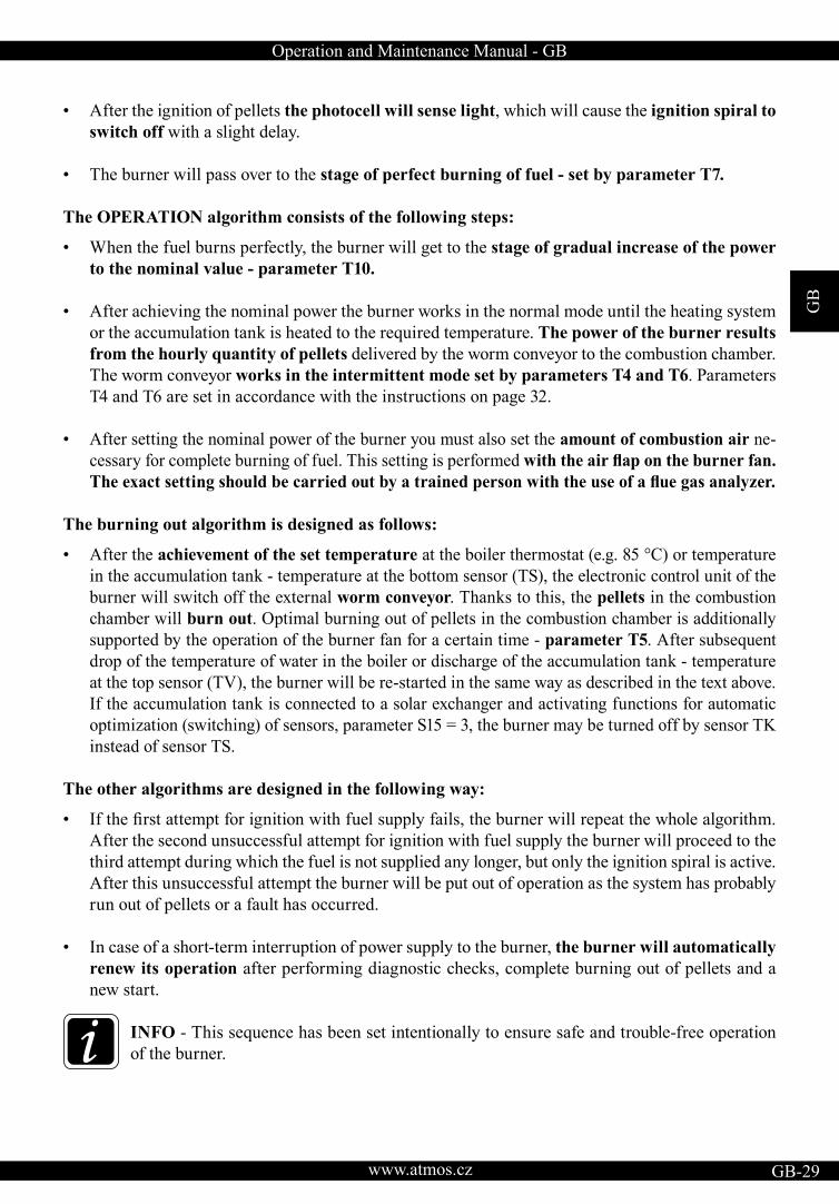
• After the ignition of pellets the photocell will sense light, which will cause the ignition spiral to switch off with a slight delay.
• The burner will pass over to the stage of perfect burning of fuel - set by parameter T7.
The OPERATION algorithm consists of the following steps:
• When the fuel burns perfectly, the burner will get to the stage of gradual increase of the power to the nominal value - parameter T10.
• After achieving the nominal power the burner works in the normal mode until the heating system or the accumulation tank is heated to the required temperature. The power of the burner results from the hourly quantity of pellets delivered by the worm conveyor to the combustion chamber. The worm conveyor works in the intermittent mode set by parameters T4 and T6. Parameters T4 and T6 are set in accordance with the instructions on page 32.
• After setting the nominal power of the burner you must also set the amount of combustion air ne-cessary for complete burning of fuel. This setting is performed with the air flap on the burner fan.The exact setting should be carried out by a trained person with the use of a flue gas analyzer.
The burning out algorithm is designed as follows:
• After the achievement of the set temperature at the boiler thermostat (e.g. 85 °C) or temperature in the accumulation tank - temperature at the bottom sensor (TS), the electronic control unit of the burner will switch off the external worm conveyor. Thanks to this, the pellets in the combustion chamber will burn out. Optimal burning out of pellets in the combustion chamber is additionally supported by the operation of the burner fan for a certain time - parameter T5. After subsequent drop of the temperature of water in the boiler or discharge of the accumulation tank - temperature at the top sensor (TV), the burner will be re-started in the same way as described in the text above. If the accumulation tank is connected to a solar exchanger and activating functions for automatic optimization (switching) of sensors, parameter S15 = 3, the burner may be turned off by sensor TK instead of sensor TS.
The other algorithms are designed in the following way:
• If the first attempt for ignition with fuel supply fails, the burner will repeat the whole algorithm.After the second unsuccessful attempt for ignition with fuel supply the burner will proceed to the third attempt during which the fuel is not supplied any longer, but only the ignition spiral is active. After this unsuccessful attempt the burner will be put out of operation as the system has probably run out of pellets or a fault has occurred.
• In case of a short-term interruption of power supply to the burner, the burner will automatically renew its operation after performing diagnostic checks, complete burning out of pellets and a new start.
INFO - This sequence has been set intentionally to ensure safe and trouble-free operation of the burner.

GB
www.atmos.cz30-GB
Operation and Maintenance Manual - GB
22. Control and setting of the burnerDisplay and control panel
The electronic control unit of the burner is equipped with four keys for easy and intuitive control.
Enter - key for confirming a command and parameter or for entering a menu
Esc - key for return from a menu
Up arrow - key for browsing in the menus or for increasing the value of a parameter
Down arrow - key for browsing in the menus or for decreasing the value of a parameter
INFO - To open the Main Menu, press the Enter key.
The PARAMETER submenu will appear on the display. To change the basic permitted parameters of the burner, confirm again - press the Enter key. To switch off OFF (STOP) or to switch on ON (START) the burner or to get to the INFORMA-TION, PASSWORD or TESTING submenus, do not confirm the (PARAMETER) submenu, but continue with the up or down arrow. Always confirm the ON (START) and OFF (STOP) command or entering the particular submenu by pressing the Enter key. In the same way you can browse and open individual menus and particular parameters in the menus. You can enter specific values ornumbers with the up ( + ) or down ( - ) arrow. Confirm the desired value with the Enter key. To return one step backwards or completely to the main screen press the Esc key once or repeatedly.
Display with keys:
1. Information about the burner status START – start-up stage RUN – normal operation STOP – burning-down stage or stand-by mode2. Temeperature TV (see page 49) – only if TS
and TV sensor are connected3. Temeperature TS (see page 49) – only if TS
and TV sensor are connected4. Symbol line – information about the operation of particular devices of the burner (see page 55)
Operation and Maintenance Manual - GB
GB
www.atmos.cz GB-31
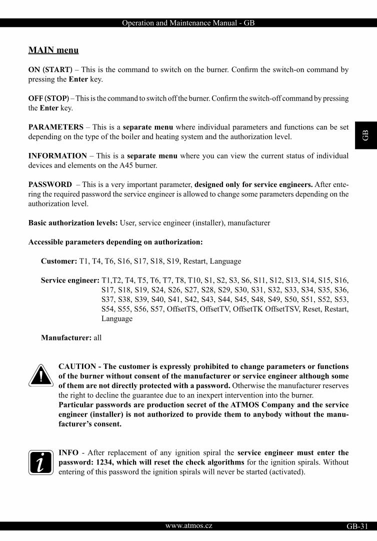
MAIN menu
ON (START) – This is the command to switch on the burner. Confirm the switch-on command bypressing the Enter key.
OFF (STOP) – This is the command to switch off the burner. Confirm the switch-off command by pressing the Enter key.
PARAMETERS – This is a separate menu where individual parameters and functions can be set depending on the type of the boiler and heating system and the authorization level.
INFORMATION – This is a separate menu where you can view the current status of individual devices and elements on the A45 burner.
PASSWORD – This is a very important parameter, designed only for service engineers. After ente-ring the required password the service engineer is allowed to change some parameters depending on the authorization level.
Basic authorization levels: User, service engineer (installer), manufacturer
Accessible parameters depending on authorization:
Customer: T1, T4, T6, S16, S17, S18, S19, Restart, Language
Service engineer: T1,T2, T4, T5, T6, T7, T8, T10, S1, S2, S3, S6, S11, S12, S13, S14, S15, S16, S17, S18, S19, S24, S26, S27, S28, S29, S30, S31, S32, S33, S34, S35, S36, S37, S38, S39, S40, S41, S42, S43, S44, S45, S48, S49, S50, S51, S52, S53, S54, S55, S56, S57, OffsetTS, OffsetTV, OffsetTK OffsetTSV, Reset, Restart, Language
Manufacturer: all
CAUTION - The customer is expressly prohibited to change parameters or functions of the burner without consent of the manufacturer or service engineer although some of them are not directly protected with a password. Otherwise the manufacturer reserves the right to decline the guarantee due to an inexpert intervention into the burner. Particular passwords are production secret of the ATMOS Company and the service engineer (installer) is not authorized to provide them to anybody without the manu-facturer’s consent.
INFO - After replacement of any ignition spiral the service engineer must enter the password: 1234, which will reset the check algorithms for the ignition spirals. Without entering of this password the ignition spirals will never be started (activated).
GB
www.atmos.cz32-GB
Operation and Maintenance Manual - GB
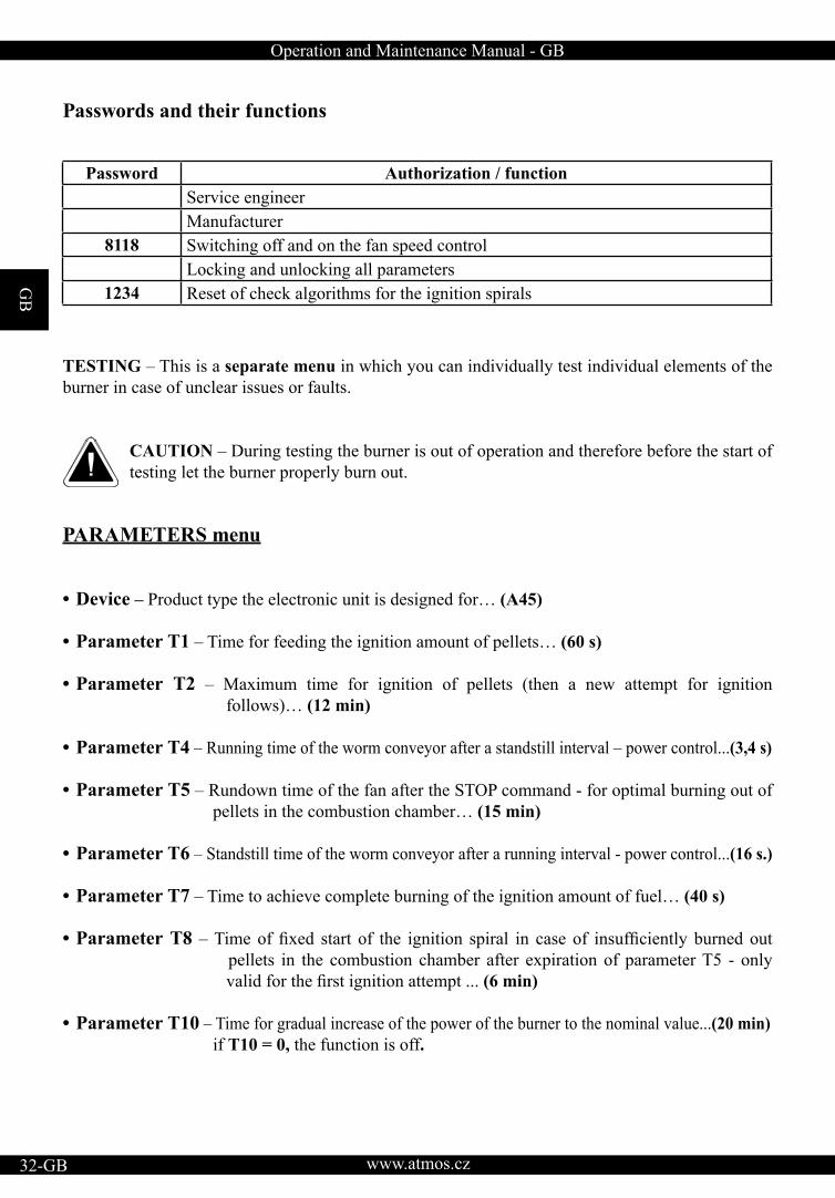
Passwords and their functions
TESTING – This is a separate menu in which you can individually test individual elements of the burner in case of unclear issues or faults.
CAUTION – During testing the burner is out of operation and therefore before the start of testing let the burner properly burn out.
PARAMETERS menu
• Device – Product type the electronic unit is designed for… (A45)
• Parameter Т1 – Time for feeding the ignition amount of pellets… (60 s)
• Parameter Т2 – Maximum time for ignition of pellets (then a new attempt for ignition follows)… (12 min)
• Parameter Т4 – Running time of the worm conveyor after a standstill interval – power control...(3,4 s)
• Parameter Т5 – Rundown time of the fan after the STOP command - for optimal burning out of pellets in the combustion chamber… (15 min)
• Parameter Т6 – Standstill time of the worm conveyor after a running interval - power control...(16 s.)
• Parameter Т7 – Time to achieve complete burning of the ignition amount of fuel… (40 s) • Parameter Т8 – Time of fixed start of the ignition spiral in case of insufficiently burned out pellets in the combustion chamber after expiration of parameter T5 - only valid for the first ignition attempt ... (6 min)
• Parameter Т10 – Time for gradual increase of the power of the burner to the nominal value...(20 min) if T10 = 0, the function is off.
Password Authorization / function Service engineerManufacturer
8118 Switching off and on the fan speed control Locking and unlocking all parameters
1234 Reset of check algorithms for the ignition spirals
Operation and Maintenance Manual - GB
GB
www.atmos.cz GB-33
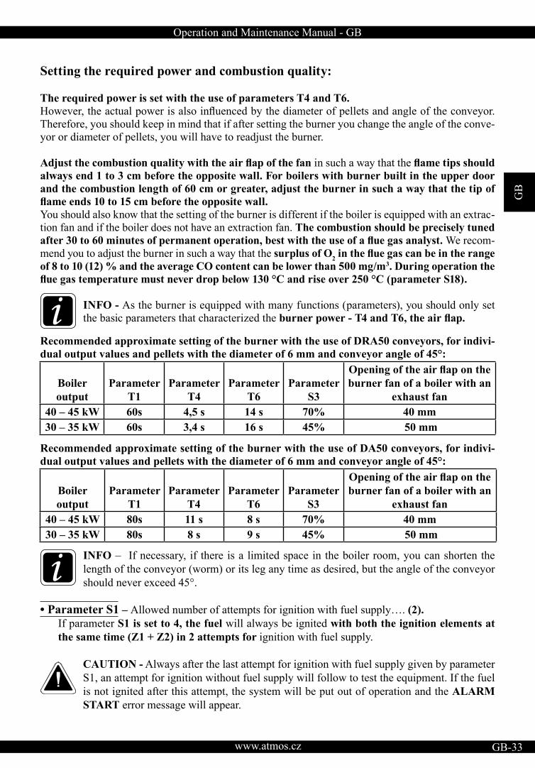
Setting the required power and combustion quality:
The required power is set with the use of parameters T4 and T6.However, the actual power is also influenced by the diameter of pellets and angle of the conveyor.Therefore, you should keep in mind that if after setting the burner you change the angle of the conve-yor or diameter of pellets, you will have to readjust the burner.
Adjust the combustion quality with the air flap of the fan in such a way that the flame tips shouldalways end 1 to 3 cm before the opposite wall. For boilers with burner built in the upper door and the combustion length of 60 cm or greater, adjust the burner in such a way that the tip of flame ends 10 to 15 cm before the opposite wall.You should also know that the setting of the burner is different if the boiler is equipped with an extrac-tion fan and if the boiler does not have an extraction fan. The combustion should be precisely tuned after 30 to 60 minutes of permanent operation, best with the use of a flue gas analyst. We recom-mend you to adjust the burner in such a way that the surplus of O2 in the flue gas can be in the rangeof 8 to 10 (12) % and the average CO content can be lower than 500 mg/m3. During operation the flue gas temperature must never drop below 130 °C and rise over 250 °C (parameter S18).
INFO - As the burner is equipped with many functions (parameters), you should only set the basic parameters that characterized the burner power - T4 and T6, the air flap.
Recommended approximate setting of the burner with the use of DRA50 conveyors, for indivi-dual output values and pellets with the diameter of 6 mm and conveyor angle of 45°:
Recommended approximate setting of the burner with the use of DA50 conveyors, for indivi-dual output values and pellets with the diameter of 6 mm and conveyor angle of 45°:
INFO – If necessary, if there is a limited space in the boiler room, you can shorten the length of the conveyor (worm) or its leg any time as desired, but the angle of the conveyor should never exceed 45°.
• Parameter S1 – Allowed number of attempts for ignition with fuel supply…. (2). If parameter S1 is set to 4, the fuel will always be ignited with both the ignition elements at the same time (Z1 + Z2) in 2 attempts for ignition with fuel supply.
CAUTION - Always after the last attempt for ignition with fuel supply given by parameter S1, an attempt for ignition without fuel supply will follow to test the equipment. If the fuel is not ignited after this attempt, the system will be put out of operation and the ALARM START error message will appear.
Boiler output
ParameterT1
ParameterT4
ParameterT6
ParameterS3
Opening of the air flap on theburner fan of a boiler with an
exhaust fan 40 – 45 kW 60s 4,5 s 14 s 70% 40 mm30 – 35 kW 60s 3,4 s 16 s 45% 50 mm
Boiler output
ParameterT1
ParameterT4
ParameterT6
ParameterS3
Opening of the air flap on theburner fan of a boiler with an
exhaust fan 40 – 45 kW 80s 11 s 8 s 70% 40 mm30 – 35 kW 80s 8 s 9 s 45% 50 mm
GB
www.atmos.cz34-GB
Operation and Maintenance Manual - GB
• Parameter S2 - fan speed at the START… (1 %) - do not change
CAUTION - 0 % = 700 rpm. If S2 = 0, the fan is off at the start.
• Parameter S3 – Fan speed during normal RUN… (100 %) In normal circumstances we do not recommend you to reduce the fan speed as it influences cooling and cleaning of inner parts of the burner. Only use the air flap to set the air quantity.
• Parameter S4 – Fuel ignition control method… (1) If:
a) S4 = 1 …. Photocell sensing
• Parameter S6 – characterizes the first reserve R - additional output - function… (1) The first reserve R is used mainly for controlling boiler exhaust fan (S6 = 4)
CAUTION – In the standard setting when parameter S1 is set to 2, you can connect to the reserve terminal (L -) an appliance with the maximum current of 2.46 A (approx. 566 VA).In the setting when parameter S1 is set to 4, which means that at the start both the ignition spirals are activated simultaneously, you can connect to the reserve terminal (L -) an applian-ce with the maximum current of 0.29 A (approx. 67 VA).
If:
a) S6 = 1…. If any fault occurs in the burner and the burner is shut down, the reserve relay will be closed and the reserve output will be energized. Thanks to this you can start a spare source of energy for heating of the building as e.g. a gas, electric or oil boiler.
b) S6 = 2….. If any fault occurs in the burner and the burner is shut down, the reserve relay will be opened and the reserve output will not be energized. Thanks to this a signal can be sent to an electrically backed up AB01 ATMOS GSM module controller that will send information that there is a system fault or the system is not energized. This is the opposite logic (to S6=1), which means that during normal operation the reserve is energized.
c) S6 = 3…… The reserve function as the output function for the burner fan, when the reserve output is closed, is energized always when the burner fan is running (fan mode only 100% or OFF). This function is applied if you want the boiler fan or extraction fan in the chimney to run together with the burner fan during burning out (the STOP mode). This function is designed for direct supply of an external fan directly from the burner.
d) S6 = 4…… The reserve function as the reversed function of the output for the burner fan, when the reserve output is off, is not energized always when the burner fan is running. This function is always activated if you connect the A45 burner with the AS25 set containing the AD02 or AD03 module, which in this case controls the extraction fan of the boiler. Install the
Operation and Maintenance Manual - GB
GB
www.atmos.cz GB-35
AD02 or AD03 module under the instrument hood of the boiler and connect it electrically between the boiler terminal board and the extraction fan, see the wiring diagram. This setting and connection with AD02 or AD03 module and special connector (jumper to main switch) is standardly used for DCxxSP boilers with the function for automatic start after wood is burnt out activated (AUTOSTART – S34 = 1 or S34 = 2). Boiler exhaust fan is run-ning simultaneously with the pellet burner during the AUTOSTART function.
e) S6 = 5…… Reserve function as the output function for the Z1 ignition spiral when the reserve copies the run of the ignition spiral.
f) S6 = 6….. Cleaning function of the combustion chamber or grill (flap). If the burner is in thenormal START, RUN and STOP mode, the output is not energized. The output is only energized for the limited time T11, which continues immediately after the expiration of time T5 in the STOP mode. It is not used with the A45 burner.
g) S6 = 7….. Reserve function as the output function for the external worm conveyor, when the reserve copies the run of the external worm conveyor (cycles between time T4 and T6). The reserve output work independently of the condition of the actual output for the external worm conveyor. This means that if the standard output for the external conveyor gets damaged, the re-serve will work independently in accordance with the same program, and therefore it can be used as a replacement for the damaged output.
h) S6 = 8….. Reserve function as the output function for the external worm conveyor, when the reserve copies the run of the external worm conveyor (cycles between time T4 and T6). The reserve works in dependence on the status of the actual output for the external worm conveyor. This means that if the output for the external conveyor gets damaged, the reserve will be switched off automatically. This function is suitable in situations when you need to control another external conveyor that supplies (feeds) pellets from a larger distance to the main conveyor from which the pellets fall directly to the burner.
i) S6 = 9….. Reserve function as the output function for the external worm conveyor, when the reserve copies the run of the external worm conveyor, but with the difference that it does not cycle, but runs permanently both during the drawing of the ignition amount and during both the times T4 and T6. Thus, the other external conveyor runs continuously and works indepen-dently of the status of the actual output for the external worm conveyor. This means that if the output to the main external conveyor from which pellets directly fall to the burner gets damaged, the reserve will keep working independently. This function can be used in cases when you need to control another external conveyor that supplies (feeds) pellets from a larger distance to a pel-let bin at the boiler from which the main external conveyor draws pellets to supply them directly to the burner. Caution - the other external conveyor must always be controlled with an additional level sensor (level meter) that will maintain the level of pellets in the pellet bin at the boiler.
j) S6 = 10….. Reserve function as the output function for the external worm conveyor, when the reserve copies the run of the external worm conveyor, but with the difference that it does not cycle, but runs permanently both during the drawing of the ignition amount and during both the times T4 and T6. Thus, the other external conveyor runs continuously, but it works in de-pendence on the status of the actual output for the external worm conveyor. This means that if the

GB
www.atmos.cz36-GB
Operation and Maintenance Manual - GB
output for the external conveyor from which pellets fall directly to the burner gets damaged, the reserve will be switched off automatically. This function is convenient in cases when you need to control another external conveyor that supplies (feeds) pellets from a larger distance to a pellet bin at the boiler from which the main external conveyor draws pellets to supply them directly to the burner. Caution - the other external conveyor must always be controlled with an additional level sensor (level meter) that will maintain the level of pellets in the pellet bin at the boiler. This is a similar function to S6 = 9, but with a higher degree of safety.
k) S6 = 11….. Reserve function for controlling boiler exhaust fan for DCxxSP boiler types when the function for automatic start after wood is burnt out is activated. This function ensures that boiler exhaust fan is running only during wood burning after the wood is burnt out. When the burner is run on pellets, the boiler exhaust fan remains switched off. This function is used if you do not need or want to use the boiler exhaust fan while the burner is running. Install the AD02 module under the instrument hood of the boiler and connect it electrically between the boiler terminal board and the extraction fan, see the wiring diagram. It is not used with the A45 burner.
WARNING – this is not a standard setting for DCxxSP boilers with the function of auto-matic start (AUTOSTART – S34 = 1 or S34 = 2) after wood is burnt out (standard setting is S6 = 4).
l) S6 = 12…..Reserve function for direct control of pump in the boiler circuit from the burner regulation (boiler terminal board). This function controls the pump in the boiler circuit without using AD02 or AD03 modules. This is applicable only for boilers that do not allow heating with wood (not even in emergency situations). E.g. D31P, P31. Pump output must be switched to re-serve R2 on the boiler terminal board and the TK sensor must be installed before this function can be activated. After activation, S37, S38, S39, S40 temperature parameters must be checked and configured.
m) S6 = 13…..Reserve function is the reverse output function for controlling the pump in the boiler circuit from the burner regulation (output cable from boiler with a connector – white inside) via AD02 or AD03 modules. This function controls the pump in the boiler circuit using AD02 or AD03 modules ranged into a set with pump thermostat installed into the boiler panel. This me-thod of pump controlling can be used for any ATMOS pellet boiler, and is therefore recom-mended. AD02 or AD03 modules must be inserted and connected under the boiler hood and the TK sensor must be installed before this function can be activated. After activation, S37, S38, S39, S40 temperature parameters must be checked and configured.
n) S6 = 14….. Reserve function for direct control of solar heating pump from the burner regulation (boiler terminal board). This function control solar pump when automatic sensor switching functi-on is activated (S15=3), where the boiler is connected with accumulation tank equipped with solar exchanger and collectors. The system requires TV, TK, TS and solar sensors to be connected to the TSV solar panel. This function never uses AD02 or AD03 modules. After activation, S26, S27, S28, S29, S30, S31, S32, S33 temperature parameters must be checked and configured.This function is specially designed for boilers: D30P, D31P, P31 a D45P
Operation and Maintenance Manual - GB
GB
www.atmos.cz GB-37
CAUTION - the direct controlling function of solar heating from pellet burner cannot be used for DCxxSP(EP) boilers and boilers with burner built into the upper doors. This function also cannot be used when the pump is simultaneously controlled in the boiler circuit from the bur-ner regulation (TK sensor cannot be simultaneously in boiler and accumulation tank)
o) S6 = 15….. Reserve function for the compressor control during the function for automatic burner cleaning using compressed air. Power element designed for switching and powering the compressor (e.g. contactor) must be connected between reserve output R and the compressor. This function is connected with S6(14), S41, S42, S43, S44, S45, S46, S47 parameter, which must be checked and configured.
p) S6 = 16….. Reserve function for controlling el.fan during the function for automatic burner cleaning using compressed air. This function is connected with S6(14), S41, S42, S43, S44, S45, S46, S47 parameter, which must be checked and configured.
Special function for turning on reserve output R according to the temperature of a concrete sensor:
a) e.g. function: TS>……. means that if the TS sensor temperature is higher then the set value in S48 parameter – Temperature A, reserve output R will be activated
b) e.g. function: TS<……. means that if the TS sensor temperature is higher then the set value in S48 parameter – Temperature A, reserve output R will be deactivated
c) e.g. function: TS,TV>……. means that if the TS and TV sensor temperature is higher at the same time then the set value in S48 parameter – Temperature A and S50 – Temperature B, reserve output R will be activated (Temperature A = first position (TS), Temperature B = second position(Tv)).
d) e.g. function TS,TK<……. means that if the TS and TK sensor temperature is higher at the same time then the set value in S48 parameter – Temperature A and S50 – Temperature B, reserve output R will be deactivated (Temperature A = first position (TS), Temperature B = second posi-tion (Tk)).
Individual functions:
(17) TS>(18) TS<(19) TV>(20) TV<(21) TK>(22) TK<(23) TSV>(24) TSV<(25) TS,TV>(26) TS,TV<
(27) TS,TK>(28) TS,TK<(29) TS,TSV>(30) TS,TSV<(31) TV,TK>(32) TV,TK<(33) TV,TSV>(34) TV,TSV<(35) TK,TSV>(36) TK,TSV<
GB
www.atmos.cz38-GB
Operation and Maintenance Manual - GB
• Parameter S7 – Function of the main external pellet conveyor – do not change in any case ... (1) if:
a) S7 = 1….. Standard function when in the START mode the external conveyor supplies the ignition amount of fuel during time T1, when it runs continuously.In the RUN mode the external conveyor doses fuel by alternating times T4 (run) and T6 (standstill).
• Parameter S10 – Specifies the behaviour of the burner in case of a power supply failure or when the boiler is activated with the main switch – do not change in any case ….. (1)
a) S10 = 1….. Function when after a power supply failure the electronic control unit tests the sta-tus of the burner, evaluating with the use of the photocell or by means of the flue gas temperaturethat the burner (boiler) is still burning. Subsequently, it first passes into the burning out mode T5 after which it proceeds to the new START immediately.
b) S10=2…… Function when after a power supply failure the electronic control unit tests the status of the burner, evaluating with the use of the photocell or by means of the flue gas temperature that the burner (bo-iler) is still burning passes over directly to the normal RUN mode in accordance with a certain algorithm.
CAUTION - Never use for the A45 burner - function for other types of devices (danger of return burning)
• Parameter S11 – Photocell sensitivity – threshold for fuel ignition……. (50 %) - do not change
• Parameter S12 – Photocell sensitivity for flame sensing - threshold for embers... (1 %) - do not change
• Parameter S13 – Fixed running time of the ignition spiral……. (0 min) - do not change Function of the ignition spiral when at every start the ignition spiral runs for a fixed time defi-ned by a direct value, independently on flame evaluation by the photocell or flue gas sensor. It isdesigned for special applications and in the case of its activation the function of automatic flamesensing from embers, characterized by parameter S12, is automatically switched off.
• Parameter S14 – characterizes the second reserve R2 - additional output - function… (0) The second reserve R2 is used mainly for controlling the pump in boiler circuit (S14 = 13)
CAUTION – In the standard setting when parameter S1 is set to 2, you can connect to the reserve R and R2 reserve terminal an appliance with the maximum current of 2.46 A (approx. 566 VA).In the setting when parameter S1 is set to 4, which means that at the start both the ignition spirals are activated simultaneously, you can connect to the reserve R and R2 terminal an applian¬ce with the maximum current of 0.29 A (approx. 67 VA).
if:
a) S14 = 1…. If any fault occurs in the burner and the burner is shut down, the reserve relay will be closed and the reserve output will be energized. Thanks to this you can start a spare source of energy for heating of the building as e.g. a gas, electric or oil boiler.

Operation and Maintenance Manual - GB
GB
www.atmos.cz GB-39
b) S14 = 2….. If any fault occurs in the burner and the burner is shut down, the reserve relay will be opened and the reserve output will not be energized. Thanks to this a signal can be sent to an electrically backed up AB01 ATMOS GSM module controller that will send information that there is a system fault or the system is not energized. This is the opposite logic (to S14=1), which means that during normal operation the reserve is energized.
c) S14 = 3…… The reserve function as the output function for the burner fan, when the reser-ve output is closed, is energized always when the burner fan is running (fan mode only 100% or OFF). This function is applied if you want the boiler fan or extraction fan in the chimney to run together with the burner fan during burning out (the STOP mode). This function is designed for direct supply of an external fan directly from the burner.
d) S14 = 4…… The reserve function as the reversed function of the output for the burner fan, when the reserve output is off, is not energized always when the burner fan is running. This function is always activated if you connect the A45 burner with the AS25 set containing the AD02 or AD03 module, which in this case controls the extraction fan of the boiler. Install the AD02 or AD03 module under the instrument hood of the boiler and connect it electrically between the boiler terminal board and the extraction fan, see the wiring diagram. This setting and connection with AD02 or AD03 module and special connector (jumper to main switch) is standardly used for DCxxSP boilers with the function for automatic start after wood is burnt out activated (AUTOSTART – S34 = 1 or S34 = 2). Boiler exhaust fan is run-ning simultaneously with the pellet burner during the AUTOSTART function.
e) S14 = 5…… Reserve function as the output function for the Z1 ignition spiral when the reserve copies the run of the ignition spiral.
f) S14 = 6….. Cleaning function of the combustion chamber or grill (flap). If the burner is in thenormal START, RUN and STOP mode, the output is not energized. The output is only energized for the limited time T11, which continues immediately after the expiration of time T5 in the STOP mode. It is not used with the A45 burner.
g) S14 = 7….. Reserve function as the output function for the external worm conveyor, when the reserve copies the run of the external worm conveyor (cycles between time T4 and T6). The reserve output work independently of the condition of the actual output for the external worm conveyor. This means that if the standard output for the external conveyor gets damaged, the re-serve will work independently in accordance with the same program, and therefore it can be used as a replacement for the damaged output.
h) S14 = 8….. Reserve function as the output function for the external worm conveyor, when the reserve copies the run of the external worm conveyor (cycles between time T4 and T6). The reserve works in dependence on the status of the actual output for the external worm conveyor. This means that if the output for the external conveyor gets damaged, the reserve will be switched off automatically. This function is suitable in situations when you need to control another external conveyor that supplies (feeds) pellets from a larger distance to the main conveyor from which the pellets fall directly to the burner.
i) S14 = 9….. Reserve function as the output function for the external worm conveyor, when the reserve copies the run of the external worm conveyor, but with the difference that it does not
GB
www.atmos.cz40-GB
Operation and Maintenance Manual - GB
cycle, but runs permanently both during the drawing of the ignition amount and during both the times T4 and T6. Thus, the other external conveyor runs continuously and works indepen-dently of the status of the actual output for the external worm conveyor. This means that if the output to the main external conveyor from which pellets directly fall to the burner gets damaged, the reserve will keep working independently. This function can be used in cases when you need to control another external conveyor that supplies (feeds) pellets from a larger distance to a pel-let bin at the boiler from which the main external conveyor draws pellets to supply them directly to the burner. Caution - the other external conveyor must always be controlled with an additional level sensor (level meter) that will maintain the level of pellets in the pellet bin at the boiler.
j) S14 = 10….. Reserve function as the output function for the external worm conveyor, when the reserve copies the run of the external worm conveyor, but with the difference that it does not cycle, but runs permanently both during the drawing of the ignition amount and during both the times T4 and T6. Thus, the other external conveyor runs continuously, but it works in de-pendence on the status of the actual output for the external worm conveyor. This means that if the output for the external conveyor from which pellets fall directly to the burner gets damaged, the reserve will be switched off automatically. This function is convenient in cases when you need to control another external conveyor that supplies (feeds) pellets from a larger distance to a pellet bin at the boiler from which the main external conveyor draws pellets to supply them directly to the burner. Caution - the other external conveyor must always be controlled with an additional level sensor (level meter) that will maintain the level of pellets in the pellet bin at the boiler. This is a similar function to S6 = 9, but with a higher degree of safety.
k) S14 = 11….. Reserve function for controlling boiler exhaust fan for DCxxSP boiler types when the function for automatic start after wood is burnt out is activated. This function ensures that boiler exhaust fan is running only during wood burning after the wood is burnt out. When the burner is run on pellets, the boiler exhaust fan remains switched off. This function is used if you do not need or want to use the boiler exhaust fan while the burner is running. Install the AD02 module under the instrument hood of the boiler and connect it electrically between the boiler terminal board and the extraction fan, see the wiring diagram. It is not used with the A45 burner.
WARNING – this is not a standard setting for DCxxSP boilers with the function of auto-matic start (AUTOSTART – S34 = 1 or S34 = 2) after wood is burnt out (standard setting is S6 = 4).
l) S14 = 12…..Reserve function for direct control of pump in the boiler circuit from the burner regulation (boiler terminal board). This function controls the pump in the boiler circuit without using AD02 or AD03 modules. This is applicable only for boilers that do not allow heating with wood (not even in emergency situations). E.g. D31P, P31. Pump output must be switched to re-serve R2 on the boiler terminal board and the TK sensor must be installed before this function can be activated. After activation, S37, S38, S39, S40 temperature parameters must be checked and configured.
m) S14 = 13…..Reserve function is the reverse output function for controlling the pump in the boiler circuit from the burner regulation (output cable from boiler with a connector – white inside) via AD02 or AD03 modules. This function controls the pump in the boiler circuit using AD02 or AD03 modules ranged into a set with pump thermostat installed into the boiler panel.
Operation and Maintenance Manual - GB
GB
www.atmos.cz GB-41
This method of pump controlling can be used for any ATMOS pellet boiler, and is therefore recommended. AD02 or AD03 modules must be inserted and connected under the boiler hood and the TK sensor must be installed before this function can be activated. After activation, S37, S38, S39, S40 temperature parameters must be checked and configured.
n) S14 = 14….. Reserve function for direct control of solar heating pump from the burner regu-lation (boiler terminal board). This function control solar pump when automatic sensor switching function is activated (S15=3), where the boiler is connected with accumulation tank equipped with solar exchanger and collectors. The system requires TV, TK, TS and solar sensors to be connected to the TSV solar panel. This function never uses AD02 or AD03 modules. After activation, S26, S27, S28, S29, S30, S31, S32, S33 temperature parameters must be checked and configured.This function is specially designed for boilers: D30P, D31P, P31 a D45P
CAUTION - the direct controlling function of solar heating from pellet burner cannot be used for DCxxSP(EP) boilers and boilers with burner built into the upper doors. This function also cannot be used when the pump is simultaneously controlled in the boiler circuit from the bur-ner regulation (TK sensor cannot be simultaneously in boiler and accumulation tank)
o) S14 = 15….. Reserve function for the compressor control during the function for automatic burner cleaning using compressed air. Power element designed for switching and powering the compressor (e.g. contactor) must be connected between reserve output R and the compressor. This function is connected with S6(14), S41, S42, S43, S44, S45, S46, S47 parameter, which must be checked and configured.
p) S14 = 16….. Reserve function for controlling el.fan during the function for automatic burner cleaning using compressed air. This function is connected with S6(14), S41, S42, S43, S44, S45, S46, S47 parameter, which must be checked and configured.
Special function for turning on reserve output R according to the temperature of a concrete sensor:
a) e.g. function: TS>……. means that if the TS sensor temperature is higher then the set value in S48 parameter – Temperature A, reserve output R will be activated
b) e.g. function: TS<……. means that if the TS sensor temperature is higher then the set value in S48 parameter – Temperature A, reserve output R will be deactivated
c) e.g. function: TS,TV>……. means that if the TS and TV sensor temperature is higher at the same time then the set value in S48 parameter – Temperature A and S50 – Temperature B, reserve output R will be activated (Temperature A = first position (TS), Temperature B = second position(Tv)).
d) e.g. function TS,TK<……. means that if the TS and TK sensor temperature is higher at the same time then the set value in S48 parameter – Temperature A and S50 – Temperature B, reserve output R will be deactivated (Temperature A = first position (TS), Temperature B = second posi-tion (Tk)).
GB
www.atmos.cz42-GB
Operation and Maintenance Manual - GB
Individual functions:
• Parameter S15 – Operation function of the burner by the two temperatures in the accumulation tank …(1)
a) S15 = 1… The function is off, the burner works based on the thermoregulator on the boiler panel
b) S15 = 2…. The function is activated and the pellet burner works based on the two temperatu-res (sensors) in the accumulation tank – TV and TS (recommended tank volume: 500 to 1000 l). The temperature of the bottom sensor (TS) is the temperature at which the burner is switched off and the fuel burns out.
The temperature of the top sensor (TV) is the temperature at which the burner is switched on again. The burner screen displays the TV and TS temperatures.
c) S15 = 3 …. The function is activated and the pellet burner works based on the two temperatu-res (sensors) in the accumulation tank – TV and TS (recommended tank volume: 500 to 1000 l). The temperature of the top sensor (TV) is the temperature at which the burner is switched on again. The temperature of the bottom sensor (TS or TK) is the temperature at which the burner is stopped.
Whether the burner is switched off based on the TS or TK sensor is decided by the temperature of the solar panel (TSV) and the temperature in the lower part of the accumulation tank (TS), where a solar exchange is built-in. If the solar panel can efficiently heat up water in the accumulation tank,the burner is turned off based on the TK sensor, so that the tank can store energy from the sun.If the energy delivered from the solar collector drops below a certain limit (temperature), the deac-tivation logic of the burner is automatically switched back to be based on the TS sensor (S26=1).However, it is possible to set that the switching may only occur after a certain period of time (S29 = 2nd digit means the length of delay between switches, in hours). Another variant is to have the burner work permanently based on the TV and TK temperatures (S26=0).
d) S15 = 4 …. The function is off and the burner works based on the TK temperature, protected by the thermoregulators on the boiler panel. After this function is activated, we need to check and possibly setup its temperature parameters S18 and S19.
CAUTION - if S15 = 2 not possible to set S6 = 14 a S14 = 14. Je-li S15 = 3 not possible to setS6 = 11, S14 = 11, S6 = 12, S14 = 12, S6 = 13, S14 = 13. Je-li S15 = 1, S15 = 4 not possible to set S14 = 14.
(17) TS>(18) TS<(19) TV>(20) TV<(21) TK>(22) TK<(23) TSV>(24) TSV<(25) TS,TV>(26) TS,TV<
(27) TS,TK>(28) TS,TK<(29) TS,TSV>(30) TS,TSV<(31) TV,TK>(32) TV,TK<(33) TV,TSV>(34) TV,TSV<(35) TK,TSV>(36) TK,TSV<
Operation and Maintenance Manual - GB
GB
www.atmos.cz GB-43
• Parameter S16 - Temperature of the top sensor (TV) at which the burner is started….. (60 °C) It is the minimum temperature of water that can be reasonably utilized in the heating system.
• Parameter S17 - The temperature of the bottom sensor ((TS, or TK for S15 = 3)) at which the burner is stopped….. (75 °C) It is the maximum temperature of water that corresponds to requirements of the heated building and the designed heat exchangers in the system (radiators and floor heating).
CAUTION – Do not set this value too high to avoid disconnection of the safety thermostat on the boiler. Always set the control thermostat on the boiler to the maximum value (95 °C). If the control thermostat on the boiler intervenes before the burner is switched off by the signal of the TS sensor in the bottom part of the accumulation tank, the system probably finds itself in thestate of hydraulic imbalance and you should check and adjust it. You can e.g. throttle the shortcut in the boiler circuit or the return line from the heating system towards the accumulation tank.
• Parameter S18 – describes the required temperature of boiler TK, which the burner is switched off at if S15=4… (85 °C)
• Parameter S19 - difference between TK temperature (for re-starting the burner) for S15 = 4…(5 K)
• Parameter S24 – maximum flue gas temperature... (250 °C)If you connect a flue gas temperature sensor (TS) to the burner and in a mode of the burner this limit value is exceeded, a warning message will appear on the display. It will notify the operator of the neces-sity to clean the heat exchanger of the boiler or the installer of the necessity to reduce the burner power to avoid unnecessary wasting of fuel. The operation of the burner is not limited by this message in any way and to clear the message you can just switch off and on the main switch on the boiler.
• Parameter S26 – is the function for defining the logic of deactivating the burner based on the TS orTK sensor, when S15=3. Connection of the boiler with a tank equipped with a solar exchanger… (1)
a) S26 = 0…. The burner permanently works based on the upper TV sensor (activation tempera-ture) and via the TK sensor (deactivation temperature). The lower part of the tank permanently has enough room for energy from the solar collector (TS sensor)
b) S26=1… the burner permanently works based on the upper TV sensor (activation temperatu-re) and the configured logic automatically takes care of switching between the middle TK sensorand lower TS sensor. Whether the burner is deactivated based on TS or TK is decided based on the temperature on the solar panel (TSV) and the temperature on the lower part of the accumulation tank (TS), where the solar exchanger is located. If the solar panel can efficiently heat up water inthe accumulation tank, the burner is turned off based on the TK sensor, so that the tank can store energy from the sun.
• Parameter S27 - activation difference of function S26 = 1… (10 K) If the temperature on the solar panel (TSV) exceeds the temperature in the lower part of the tank by the activation difference, the boiler deactivation function will be switched from the bottom TS sensor to the middle TK sensor.If a function for solar panel pump control is activated directly from the boiler regulation (S6 = 14 or S14 = 4), the same logic will be used to activate the solar pump.
GB
www.atmos.cz44-GB
Operation and Maintenance Manual - GB
• Parameter S28 – deactivation difference of function S26 = 1… (3 K) If the temperature on the solar panel (TSV) exceeds the temperature in the lower part of the tank
by the deactivation difference, the boiler deactivation function will be switched from the middle TK sensor to the bottom TS sensor.
If a function for solar panel pump control is activated directly from the boiler regulation (S6 = 14 or S14=4), the same logic will be used to activate the solar pump.
• Parameter S29 – is the function for delaying the automatic switching from the TK sensor back to the TS sensor for controlling the burner based on two temperatures (sensors, S15 = 3)… (0 hours)
This function will cause the function for deactivating the burner to be switched from the middle TK sensor to the bottom TS sensor after the time listed in parameter S29 passes, if the temperature on the solar panel TSV is lower or greater only by the deactivation difference (Parameter S28) than the temperature in the lower part of the tank where the solar exchange is located.
The set value means the number of hours, e.g.: S29 = 2 means a switch delay of 2 hours.
• Parameter S30 – is the function of the minimal operating time of the solar pump when the condi-tions for its activation and then deactivation are met (function S15 = 3)… (3 min )
The set value means the number of minutes, e.g.: S30 = 3 means 3 minutes
• Parameter S31 – characterizes the required temperature TS in the lower part of the accumulation tank where the solar exchanger is located, during the function of charging the accumulation tank by the solar collector. (function S15 = 3)… (75 °C)
Once it is reached, the solar pump will be turned off.
• Parameter S32 – characterizes the maximum temperature TV in the accumulation tank during the function of charging the accumulation tank by the solar collector (function S15 = 3)… (100 °C)
The solar pump will be turned off if it is exceeded.
• Parameter S33 – characterizes the maximum temperature TSV of the solar collector, for which the solar pump will still remain in operation (function S15 = 3) …(115 °C)
The solar pump will be turned off if it is exceeded.
• Parameter S34 – is the function of automatically starting the pellet burner (AUTOSTART) after the wood burns out. The function is specially created for DCxxSP( EP ) burners, however it may also be used for two separate boilers …. (0) It is not used with the A45 burner.
a) S34 = 0…. The automatic start function is off
b) S34 = 1…. The automatic start function is on. The pellet burner will be turned on when the temperature of exhausts TSV drops below the set value (S36 = 80), e.g. below 80 °C
c) S34 = 2…. The automatic start function is on. The pellet burner will be turned on when two conditions are met:
- the temperature of the boiler TK drops below the set value (S35 = 75), e.g. below 75 °C - the temperature of exhausts TSV drops below the set value (S36 = 80), e.g. below 80 °C
Operation and Maintenance Manual - GB
GB
www.atmos.cz GB-45
If the function (parameter S34) is turned on in the boiler, the following practice is used for boilers DCxxSP(EP):
If the boiler is burning out but the wood container still contains enough wood, we may directly switch the boiler switch from wood to pellets.
The pellet burner will perform a DIAGNOSTIC which will be used to ascertain the current status of the boiler (temperature of exhausts, temperature of the boiler, temperature in the accumulation tank)
If the conditions for immediate start of the burner are not met (see above), the burner will remain on standby, where the flue exhaust fan will remain in operation (if set) so that the wood can pro-perly finish burning (S6=4). AUTOSTART will start flashing on the boiler screen.
If the AUTOSTART sign flashes slowly, the conditions set by the function (S34 = 1 or S34 = 2) are not met.
If the AUTOSTART sign flashes quickly, the previous conditions are met, but the conditions set by function (S15=2) are not, which means that the temperature on the accumulation tank did not drop below the value set by S16 or the regulation thermoregulator on the boiler is not activated, i.e. the end switch is not pressed (a star is not displayed on the boiler screen near the thermoregulator symbol)
If all the conditions are met, the burner will start automatically.
INFO – In case of an electric outage, the burner will perform a DIAGNOSTIC and, if all conditions are met, will burn out and return to normal operation. Otherwise it will await the fulfillment of previous conditions (drop of exhaust and water temperature).If we want to use wood to heat up the boiler, it suffices to place the switch on the wood po-sition. However, it is better to first keep the switch on the „0“ position for 10 - 15 minutes sothat the burner can properly burn out. This is an ideal time to prepare the fuel for stoking.
• Parameter S35 – characterizes the limit (max.) temperature of the boiler TK, during which the burner will automatically start during the AUTOSTART function (S34 = 2)… (75 °C)
• Parameter S36 – characterizes the limit (max.) temperature of the exhausts TSV, during which the burner will automatically start during the AUTOSTART function (S34 = 2)… (80 °C)
WARNING – after placing the exhaust sensor TSV on a side of the burner flue pipe, theTSV temperature is not the exact temperature of the exhausts but the difference temperature for the automatic start function. If we want to place the exhaust sensor directly on or into the flue pipe to measure the exhaust temperature precisely, it is necessary to always use a sensorwith a higher heat resistance of up to 400 °C.
• Parameter S37 – characterizes the requires temperature of the boiler TK during which the pump in the boiler circuit will be activated. This will only occur if the required temperature is reached and the boiler is in OPERATION or burn-out mode (S14=13 with modules AD02 or AD03)… (80 °C)
It is also necessary to re-check or set parameters S38, S39, S40
GB
www.atmos.cz46-GB
Operation and Maintenance Manual - GB
• Parameter S38 – deactivation difference for parameter S37, of the pump in the boiler circuit (S14 = 13 or S6 = 13)… (2 K)
If the temperature of the boiler TK drops by more than the deactivation difference S38, the pump in the boiler circuit will be turned off in the OPERATION or STOP (burn-out) modes.
• Parameter S39 – characterizes the emergency temperature of the boiler TK, during which the pump in the boiler circuit will be activated (S14 = 13 with modules AD02 or AD03)… (93 °C)
Activation will be carried out regardless of special functions of the burner (function S40). The function works based on the deactivation difference specified in parameter S38.
• Parameter S40 – is the function for after-running of the pump in the boiler circuit used based on boiler type (S14 = 13, S6 = 13)… (0)
a) S40 = 0…. The automatic deactivation function for the pump in the the boiler circuit after the pellet burner burns out is off (after the time specified in parameter T5 runs out). The pump willbe switched off after the temperature of the boiler TK drops (S38, S39). Designated for ceramic boilers with a large momentum (with the option of stoking with wood).
b) S40 = 1... The automatic deactivation function for the pump in the boiler circuit after the pellet burner burns out is on. The pump will be switched off immediately after the burner burns out, after the time specified in parameter T5 runs out. The function designated by parameter S39 is active. De-signated for boilers with minimal momentum without ceramics (D14P, P14, D21P, P21, D25P, P25).
• Parameter S41 – is the function for automatic cleaning of the burner by compressed air after a certain number of work cycles (burn-outs). The function utilizes both reserve outputs (S16 = 15, S14 = 16) – nonstandard function… (4)
a) S41 = 1 - 9… function when the cleaning of the burner will be performed only once after running a given number of cycles (1, 2, 3, 4, 5, 6, 7, 8, 9 - number of cycles)
b) S41 = 11 - 19… function when the cleaning of the burner will be performed always twice after running a given number of cycles (11 = 1, 12 = 2, 13 = 3, 14 = 4, 15 = 5, 16 = 6, 17 = 7, 18 = 8, 19 = 9 - number of cycles) (from 1.4.2013)
If the parameter S41 = 0 or 10, the function is turned off.
• Parameter S42 – is the function for automatic cleaning of the burner by compressed air after a certain period of operation. On the subsequent termination of a work cycle (burnout), the burner mouth will be cleaned. The function utilizes both reserve outputs (S16 = 15, S14 = 16) – nonstan-dard function… (6 hours)
After the time S42 runs out the pellet burner burns out and cleans. AUTO STOP will be shows on the burner screen.
The set value represents the actual time in hours.
• Parameter S43 – is the function for automatic cleaning of the burner by compressed air after a cer-tain period of operation. After the set period elapses, the burner will immediately stop, be cleaned and re-started if necessary and all conditions for START are met (regardless of parameters S41 and S42). The function utilizes both reserve outputs (S16 = 15, S14 = 16) – nonstandard function… (12 hours)
The set value represents the actual time in hours.
Operation and Maintenance Manual - GB
GB
www.atmos.cz GB-47
• Parameter S44 – is the compressor function for automatic cleaning of the burner by compressed air, which determines the duration of compressor operation used for preparing a sufficient amountof compressed air (pressure function S6 = 15) - nonstandard function… ( 2 min )
The set value represents the actual time in minutes.
• Parameter S45 – is the electric valve function for automatic cleaning of the burner by compressed air, which determines how long the el. valve is open to perfectly clean the combustion chamber of the burner (S14 = 16) - nonstandard function… (2 s)
The set value represents the actual time in seconds.
• Parameter S46 – is the burner fan function which sets the type of used fan with rotation scanning. Number of impulses.… (12-EBM)
• Parameter S47 – is the function of fan 2 which sets the type of used fan with rotation scanning.
Number of impulses – do not change the factory setting… (0)
a) S47 = 12 - EBM..... radial blower of the burner
b) S47 = 4 - ATAS..... exhaust blower of the boiler
c) S47 = 0..... second method for switching off the blower 2 speed sensing
• Parameter S48 – characterizes temperature TEMPERATURE A in the applications of function S6 = 17 to 36… (75 °C)
This is a free function for the reserve output R on the first position (Temperature A = first positionin function S6 = 17 to 36).
• Parameter S49 – characterizes the activation or deactivation difference for TEMPERATURE A in the applications of function S6 = 17 to 36… (5K)
This is the difference for the free function of reserve output R on the first position (difference forTemperature A = difference for the first position in the function S6 = 17 to 36).
• Parameter S50 – characterizes TEMPERATURE B in the applications of function S6 = 25 to 36...….(75 °C)
This is a free function for the reserve output R on the first position (Temperature b = second posi-tion in function S6 = 25 to 36).
• Parameter S51 – characterizes the activation or deactivation difference for TEMPERATURE B in the applications of function S6 = 25 to 36… (5K)
This is the difference for the free function of reserve output R on the first position (difference forTemperature B = difference for the first position in the function S6 = 25 to 36).
• Parameter S52 – characterizes TEMPERATURE C in the applications of function S6 = 25 to 36...… (75 °C)
This is a free function for the reserve output R2 on the first position (Temperature b = second po-sition in function S14 = 17 to 36).
• Parameter S53 – characterizes the activation or deactivation difference for TEMPERATURE C in the applications of function S14 = 17 to 36… (5K)
This is the difference for the free function of reserve output R2 on the second position (difference for Temperature C = difference for the second position in the function S14 = 17 to 36).

GB
www.atmos.cz48-GB
Operation and Maintenance Manual - GB
• Parameter S54 – characterizes TEMPERATURE D in the applications of function S14 = 25 to 36…. (75 °C)
This is a free function for the reserve output R2 on the first position (Temperature b = second po-sition in function S14 = 25 to 36).
• Parameter S55 – characterizes the activation or deactivation difference for TEMPERATURE D in the applications of function S14 = 25 to 36… (5K)
This is the difference for the free function of reserve output R2 on the second position (difference for Temperature D = difference for the second position in the function S14 = 25 to 36).
• Parameter S56 – characterizes control of functioning (speed sensing) of the exhaust blower of the boiler (blower 2); setting may be different according to use – must never be changed...... (0)
a) S56 = 0 ..... control of the exhaust blower of the boiler turned off
a) S56 = 1 ..... control of the exhaust blower of the boiler turned on
If S56 = 1, parameters S47 and S57 are activated (visualized). • Parameter S57 – characterizes minimum (safety) speed of the blower 2....... (1,000 rpm) adjustable range ..... 1,000 – 3,200 rpm It is a function of the control of proper functioning of the exhaust blower of the boiler. When the blower is running at the speed lower than set, “ALARM VENT 2” is declared.
• Parameter S58 – characterizes the amount of compressed air for the firstpre-cleaningoftheburnerwhen installing pneumatic cleaning the burner. This is the time at which the partial fillingcompres-sor air tank for pre-cleaning of the burner ... (6 s) - standardly do not change
• Offset TV – This function is used to compensate the offset of the TV temperature sensor (input) in the range of ± 9.9 °C.
• Offset TS – This function is used to compensate the offset of the TS temperature sensor (input) in the range of ± 9.9 °C.
• Offset TK – This function is used to compensate the offset of the TK temperature sensor (in-put) in the range of ± 9.9 °C
• Offset TSV – This function is used to compensate the offset of the TSV temperature sensor (input) in the range of ± 9.9 °C
• Reset – By means of this function you can use one command to reprogram the electronic unit of the burner to the default settings.
• Restart – By means of this function you can use one command to reprogram the electronic unit of the burner to the settings last set by the installer (under the installer code).
This allows the resetting of the control unit without changing the system settings in case of any problems.
Operation and Maintenance Manual - GB
GB
www.atmos.cz GB-49
• Calibr. – This function makes it possible to calibrate inputs for temperature sensors with the use of special calibration aids – function for the manufacturer only.
• Language – This is the selection function of the language in which the burner communicates with the user.
The basic version of the program contains these language versions:
CZ - Czech, DE - German, EN - English, FR - French, IT - Italian, SP - Spanish, SE - Swedish, PO - Portuguese, RO - Romanian, PL - Polish, HU - Hungarian and IT - Italian
INFORMATION menu
• Photocell – Displays the current value that the photocell sees.
• Temperature TS – displays the current TS temperature - (exhaust temperature (S15 = 1) or lower temperature (S15 = 2))
• Temperature TV – displays the current TV temperature - (water temperature (S15 = 1) or upper temperature (S15 = 2))
• Temperature TK – displays the current TK temperature - (boiler temperature ( S15 = 1, S15 = 2, S15 = 4, S6 = 12, S6 = 13, S14 = 12, S14 = 13), central tank temperature ( S15 = 3, S6 = 14, S14 = 14 ), central tank temperature as a second deactivation sensor for burner TS2 (S26 = 0))
• Temperature TSV – displays the current TSV temperature - (exhaust temperature (S15 = 1, S15 = 2, S15 = 4, S34 = 1, S34 = 2), solar collector temperature (S15 = 3, S6 = 14, S14 = 14))
Short explanation:This always depends on whether the burner regulation function based on two temperatures on the accumulation tank is on or off, and whether the automatic start function after wood burns out is ac-tivated. The default settings are S15=1 and S34=0, which means that the function for controlling the burner by two sensors is deactivated and the AUTOSTART function for DCxxSP(EP) burns is also off. The burner is only controlled by thermoregulators on the boiler panel. The customer may connect the exhaust temperature sensors TS and TSV and the water temperature sensors TV and TK to the burner so that they only serve as information.
If we set S15 = 2, the function for regulation by two temperatures on the tank is activated and so we connect the water tempearture sensor in the lower part of the tank TS and the water tempe-rature sensor in the upper part of the tank TV to the clamps of the burner connector.
If we set S15=3, the function for regulation by two temperatures on the tank is also activated, simultaneously with the solar functions. It is thus also necessary to connect the TK sensor loca-ted in the middle of the accumulation tank between the TV and TS sensors and the TSV solar collector sensor.
If we are going to use the AUTOSTART function for boilers DCxxSP (S34 = 1 or S34 = 2), we must also connect the TK sensor as a boiler sensor and the TSV sensor as the exhaust tempera-ture sensor. It is not used with the A45 burner.
GB
www.atmos.cz50-GB
Operation and Maintenance Manual - GB
If we are going to control the pump in the boiler circuit (recommended S14 = 12 or S14 = 13), we must always connect the TK sensor.
• Fan speed - displays the current speed of the fan
• Fan speed 2 – displays the current speed of fan 2 (not used)
• Conveyor - displays the current status of the conveyor
• Conveyor faults - displays information for the service engineer • Spirals - displays the current status of the ignition spirals
• Spiral faults - displays information for the service engineer
• Reserve R - displays the current status of the reserve output R (parameter S6)
• Reserve R2 - displays the current status of the reserve output R2 (parameter S14)
TESTING menu
• Autotest – This function is used for automatic testing of all the basic elements of the burner as the fan, conveyor, ignition spirals, etc. The testing is carried out consecutively in 20-second intervals so that the engineer can monitor the operation of individual devices. If this test is not sufficient,individual devices can be run separately, namely with the use of the following functions.
CAUTION – During testing the burner is put out of operation, therefore before the start of testing always let the burner properly burn out with the use the STOP command.
• Fan - this function is used to test the operation of the fan
• Conveyor - this function is used to test the operation of the conveyor
• Spiral 1 - this function is used to test the operation of the ignition spiral 1
• Spiral 2 - this function is used to test the operation of the ignition spiral 2
• Reserve R – this function is used to test the switching device (relay) of the reserve output R
• Reserve R2 – this function is used to test the switching device (relay) of the reserve output R2
• Photocell - used to test the photocell. Conduct the test by observing its sensitivity when it is inserted in the burner or outside the burner in the natural light (never on the sun – will cause an alarm).
Operation and Maintenance Manual - GB
GB
www.atmos.cz GB-51
23. Information - error messages - troubleshootingGeneral troubleshooting
CAUTION - All interventions into the electric systems must be performed by a qualifiedperson that has read the operation manual and has been trained by the manufacturer.
The equipment is not working:
If you come to a boiler with a burner that has been put out of operation, proceed as follows:
- Check whether the boiler and burner are energized, if so- Check whether the tank is filled with pellets - Check whether the conveyor is filled with pellets after it has run out of pellets (must always be drawn before a new start, see the instructions), if so - Read the error message on the burner display and find the error in the table below
WARNING – if the burner did not call any ALARM, it is not maufnctioning and is performing its own testing. Do not reset it by shutting off the power supply (switch), wait for the alarm to sound or normal operation (wait 1 hour).
Table of error messages on the display - alarms
Alarm no.
Message on the display
Meaning Remedy
1 ALARM CRC Wrong program checksum - error of the electronic unit
Replace the electronic con-trol unit
2 ALARM SENSOR TV
Failure of the sensor of water temperature in the boiler or temperature in the top part of the tank (TV) - the sensor is short-circuited (damaged) or disconnected
Check the connection of the sensor in the burnerCheck the cable and sensor for damage Repair or replace
3 ALARM SENSOR TS
Failure of the sensor of fluegas temperature or water tem-perature in the bottom part of the tank (TS) - the sensor is short-circuited (damaged) or disconnected
Check the connection of the sensor in the burnerCheck the cable and sensor for damage Repair or replace
GB
www.atmos.cz52-GB
Operation and Maintenance Manual - GB
4 ALARM SENSOR TK
Failure of the boiler tempera-ture sensor TK in the boiler or in the middle part of buffer tank – the sensor is short-circuited (damaged) or disconnected
Check the connection of the sensor in the burnerCheck the cable and sensor for damage Repair or replace
5 ALARM SENSOR TSV
Failure of the waste gas or so-lar sensor TSV – the sensor is short-circuited (damaged) or disconnected
Check the connection of the sensor in the burnerCheck the cable and sensor for damage Repair or replace
6 ALARM VENTILATOR
Failure of the fan or fan speed sensor
Check the cable of the speed sensor and its connectors Check whether the fan does not size, it must be possible to turn it easily by hand Check the fuse on the electron-ic board for the fan (1.0 A) Repair or replace
7 ALARM VENT 2
the same as ALARM VENTILATORFailure of the exhaust blower of the boiler or defective ca-pacitor under the hood of the boiler
the same as ALARM VENTILATORChange the starting capacitor for the exhaust fanChange the exhaust fan of the boiler.
8 ALARM RELE Error at the output for the ex-ternal conveyor (neither out-put is functional)
The external conveyor does not feed fuel to the burner
Check and if necessary re-place the fuse for the convey-or (0.8 A) Check the wiring between electronic board and socket Broken gearbox of the con-veyor or output for conveyor control
If you are not using the re-serve, reconnect the convey-or terminals to the reserve and set the parameter S6 = 7. If you use the reserve for other applications, replace the electronic control unit.

Operation and Maintenance Manual - GB
GB
www.atmos.cz GB-53
9 ALARM SPIRAL Failure of both the ignition spirals
Check and replace both the ignition spirals and check and replace faulty fuses (3.15 A) on the electronic board Enter the activation code: 1234
10 ALARM START All the allowed start (ignition) attempts have been exhaustedThere are no more pellets or the bin is empty
Faulty ignition spirals
Faulty photocell
Replenish fuel, draw pellets to the conveyor and turn of and on the main switch on the boiler
Check the supply wires of the ignition spirals, check the fuses (3.15 A), check the igni-tion elements with the func-tion in the TESTING menu
Check the supply cable of the photocell with the con-nector, test the photocell with the use of the function in the TESTING menu
11 ALARM PHOTOCELL
Flame sensing error in the OP-ERATION mode
Clean the photocellIf necessary, replace
CAUTION – In case of the ALARM SPIRAL error message you must always replace both the ignition spirals and enter the activation code 1234. If after the replacement of the ignition spirals and entering of the code the burner does not ignite (no ignition element is heating), replace the AC07X electronic control unit and use the reserve output for full con-trol of one ignition spiral. In such a case set the parameter S6 = 5 or S14 = 5..
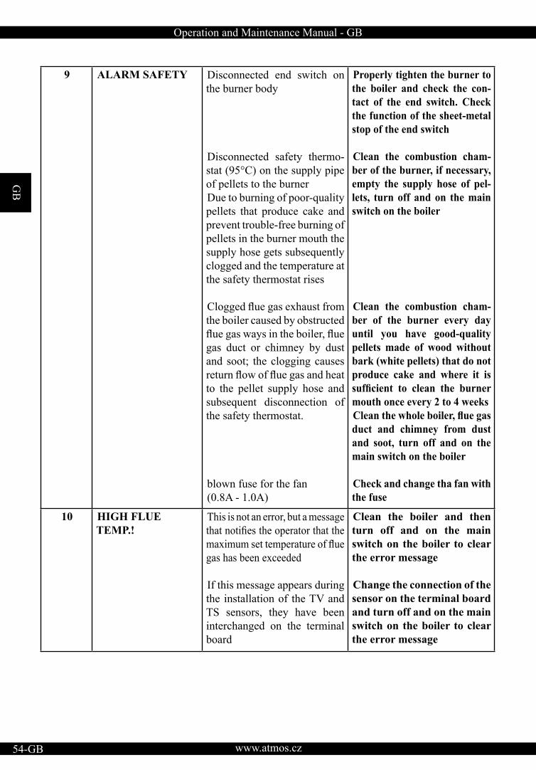
GB
www.atmos.cz54-GB
Operation and Maintenance Manual - GB
9 ALARM SAFETY Disconnected end switch on the burner body
Disconnected safety thermo-stat (95°C) on the supply pipe of pellets to the burner Due to burning of poor-quality pellets that produce cake and prevent trouble-free burning of pellets in the burner mouth the supply hose gets subsequently clogged and the temperature at the safety thermostat rises
Clogged flue gas exhaust fromthe boiler caused by obstructed flue gas ways in the boiler, fluegas duct or chimney by dust and soot; the clogging causes return flow of flue gas and heatto the pellet supply hose and subsequent disconnection of the safety thermostat.
blown fuse for the fan (0.8A - 1.0A)
Properly tighten the burner to the boiler and check the con-tact of the end switch. Check the function of the sheet-metal stop of the end switch
Clean the combustion cham-ber of the burner, if necessary, empty the supply hose of pel-lets, turn off and on the main switch on the boiler
Clean the combustion cham-ber of the burner every day until you have good-quality pellets made of wood without bark (white pellets) that do not produce cake and where it is sufficient to clean the burnermouth once every 2 to 4 weeks Clean the whole boiler, flue gasduct and chimney from dust and soot, turn off and on the main switch on the boiler
Check and change tha fan with the fuse
10 HIGH FLUE TEMP.!
This is not an error, but a message that notifies the operator that themaximum set temperature of fluegas has been exceeded
If this message appears during the installation of the TV and TS sensors, they have been interchanged on the terminal board
Clean the boiler and then turn off and on the main switch on the boiler to clear the error message
Change the connection of the sensor on the terminal board and turn off and on the main switch on the boiler to clear the error message
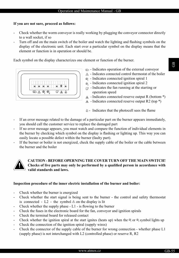
Operation and Maintenance Manual - GB
GB
www.atmos.cz GB-55
If you are not sure, proceed as follows:
- Check whether the worm conveyor is really working by plugging the conveyor connector directly to a wall socket, if so
- Turn off and on the main switch of the boiler and watch the lighting and flashing symbols on thedisplay of the electronic unit. Each start over a particular symbol on the display means that the element or function is in operation or should be.
Each symbol on the display characterizes one element or function of the burner.
- Indicates operation of the external conveyor - Indicates connected control thermostat of the boiler - Indicates connected ignition spiral 1- Indicates connected ignition spiral 2 - Indicates the fan running at the starting or operation speed - Indicates connected reserve output R (bottom *)- Indicates connected reserve output R2 (top *)
- Indicates that the photocell sees the flame
- If an error message related to the damage of a particular part on the burner appears immediately, you should call the customer service to replace the damaged part - If no error message appears, you must watch and compare the function of individual elements in the burner by checking which symbol on the display is flashing or lighting up. This way you can easily locate a possible defect within the burner (faulty part). - If the burner or boiler is not energized, check the supply cable of the boiler or the cable between the burner and the boiler
CAUTION - BEFORE OPERNING THE COVER TURN OFF THE MAIN SWITCH! Checks of live parts may only be performed by a qualified person in accordance withvalid standards and laws.
Inspection procedure of the inner electric installation of the burner and boiler:
- Check whether the burner is energized - Check whether the start signal is being sent to the burner - the control and safety thermostat is connected - L2 - the symbol on the display is lit - Check whether the supply phase - L1 - is flowing to the burner- Check the fuses in the electronic board for the fan, conveyor and ignition spirals - Check the terminal board for released contact - Check whether the ignition spiral at the start ignites (heats up) when the or symbol lights up- Check the connection of the ignition spiral (supply wires)- Check the connector of the supply cable of the burner for wrong connection - whether phase L1 (supply phase) is not interchanged with L2 (controlled phase) or reserve R, R2
GB
www.atmos.cz56-GB
Operation and Maintenance Manual - GB
If no problem has been found, reset the regulation AC07X by the RESTART command.
If the system is working, but you are not satisfied with its function, proceed as follows:
Check the quality of pellets • Heating value - whether they are really pellets made of wood or whether something has been ad-
ded to them - crumble them and smell • Colour - caking - white pellets do not cake, dark pellets or pellets with dark dots that contain bark
cake - in such a case the combustion chamber must be cleaned once a day! If it is not enough to clean the combustion chamber once a day, the pellets contain chemicals which
do not allow pellets to be burned in the A45 burner (biologic waste). Replacement required.• Dust in pellets - causes uneven operation of the burner and clogging of the burner hose• Size - too small pellets - reduce the burner power (Ø 5 x 5 mm), long pellets do not fall freely to
the burner and clog the supply pipe.
Check the flue gas temperature • It should be in the optimal range (150 ÷ 200 °С). • If the temperature is too low, reduce the power of the burner (decrease parameter T4 and increase
T6) and reduce the quantity of combustion air or clean the boiler. • If the temperature is too low, increase the power of the burner and quantity of combustion air (in-
crease parameter T4).
Check the level of pellets in the burner mouth • If it is too low and the burner goes out, check the flue gas temperature (see above). Reduce the
quantity of combustion air or increase the quantity of supplied pellets - increase the power (increase parameter T4).
• If the pellet level in the burner mouth is too high and the burner exhibits poor combustion - produces smoke, increase the quantity of combustion air or reduce the quantity of supplied pellets - reduce the power (decrease parameter T4).
At the start check how long it takes for combustion quality to improve - how long smoke is released from the chimney • If smoke is released from the chimney at the start for more than 5 minutes, extend the time of gradual increase to the nominal power (parameter T10, e.g. increase by 5min). Be careful about the setting of the air flap.
The burner regularly does not ignite at the first attempt, but always at the second one• Extend the time for the supply of ignition fuel (parameter T1 e.g. by 10 s), extend time T2 for ig-
nition of pellets (e.g. to 12 minutes) or reduce the angle of the conveyor (max. 45°).
If after stopping of the burner and its burning out a lot of glowing unburnt pellets remain in the combustion chamber (mouth) of the burner • Extend the rundown time of the fan - parameter T5 (e.g. extend the time by 5 minutes) - never shorten

Operation and Maintenance Manual - GB
GB
www.atmos.cz GB-57
24. Maintenance and cleaning of the burner The system for burning wooden pellets is designed in such a way to require minimum maintenan-ce. The necessary degree of maintenance directly depends on the set power of the burner and quality of used pellets.
CAUTION - Before starting repair or maintenance work during which you will handle the burner always turn off the power supply with the main switch of the boiler or dis-connect to supply cable of the burner with the connector!
Regular removal of ashes:
Burning of wooden pellets leaves approximately 1 to 2 % of ashes. In practice you will gradually find out how often the burner should be cleaned depending on the set power, intensity of heating andquality of used fuel. Before the start of cleaning you must first shut down the burner and let the fuelburn out, best by reducing the temperature on the control thermostat or by turning off the burner switch on the boiler panel. The common interval of cleaning the burner mouth and boiler varies in the range of 7 to 30 days (after burning of 300 to 1000 kg of high-quality pellets). You should remove ashes from the burner mouth by removing the combustion chamber from the burner mouth and knocking it out. Then remove ashes from the combustion space of the boiler and clean the heat exchanger of the boiler (tube plate) as described in the boiler manual.
CAUTION - Always put ashes in a closed vessel. During the removal of ashes and cleaning of the combustion chamber use means of personal protection (gloves and protective goggles).
Annual maintenance
• At least once a year you must perform a complete check, maintenance and inspection of the burner during which the burner must be removed from the boiler.
• During this maintenance remove and wipe the photocell that senses the flame.
• Thoroughly clean the space under the combustion chamber of the burner and behind the ignition spiral. Disassemble the inlet pipe through which pellets fall to the burner and clean it.
• Dismount the covering metal sheet of the burner mouth attached with one screw and clean the space under it where pellets fall and burn (scrape off dust and deposits). Clean the opening through which the photocell sees the flame.
• Knock dust out of the flexible supply hose and visually check whether it is not perforated. In such a case repair it or replace. On that occasion check the worm of the external conveyor by inspecting it from the bottom where pellets fall into the flexible hose. Check whether is it not strangled by some objects, e.g. wound strings, a piece of wood, etc. that are sometimes found in pellets.
• Then, assemble and seat everything in the boiler. Tighten all the connections.
GB
www.atmos.cz58-GB
Operation and Maintenance Manual - GB
• Finally, check the basic functions and safety of the electronic unit in the TESTING and INFORMATION submenus, see page 49 and 50. Check the function of the end switch and 95° safety thermostat at the pellet inlet to the burner (contact of the thermostat with the pipe), see page 10 and 11.
CAUTION - It is prohibited to do welding work on the equipment if the system is connected to the electric mains and the electronic control unit is not removed. It might get damaged. If the customer is not able to carry out the annual inspection and maintenance of the burner by themselves, this service may be ordered from a service engineer. This service is subject to a fee. Make a record of the annual maintenance and inspection in the operation manual on page 63.
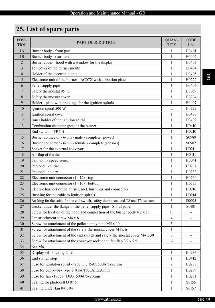
Operation and Maintenance Manual - GB
GB
www.atmos.cz GB-59
25. List of spare parts POSI-TION PART DESCRIPTION QUAN-
TITY CODE 1 pc
1A Burner body - front part 1 H04011B Burner body - rear part 1 H04022 Burner cover - hood with a window for the display 1 H04033 Top cover of the burner mouth 1 H04044 Holder of the electronic unit 1 H04055 Electronic unit of the burner - AC07X with a fixation plate 1 H02226 Pellet supply pipe 1 H04067 Safety thermostat 95 °C 1 H00598 Safety thermostat cover 1 H02249 Holder - plate with openings for the ignition spirals 1 H040710 Ignition spiral 500 W 2 H022911 Ignition spiral cover 1 H040812 Inner holder of the ignition spiral 1 H040913 Combustion chamber (pot) of the burner 1 H041014 End switch - FR501 1 H021015 Burner connector - 6-pin - male - complete (power) 1 S098916 Burner connector - 6-pin - female - complete (sensors) 1 S098717 Socket for the external conveyor 1 H021118 Air flap of the fan 1 H041119 Fan with a speed sensor 1 H004120 Photocell - entire 1 H023121 Photocell holder 1 H023222 Electronic unit connector (1 - 12) - top 1 H026023 Electronic unit connector (1 - 16) - bottom 1 H023524 Electric harness of the burner, incl. bushings and connectors 1 H021625 Bushing for the cable to ignition spirals 1 H021426 Bushing for the cable for the end switch, safety thermostat and TS and TV sensors 3 S009527 Gasket under the flange of the pellet supply pipe - Sibral paper 1 S018128 Screw for fixation of the hood and connection of the burner body 4.2 x 13 18 -29 Fan attachment screw M4 x 8 4 -30 Screw for attachment of the pellet supply pipe M5 x 10 3 -31 Screw for attachment of the safety thermostat cover M4 x 6 1 -32 Screw for attachment of the end switch and safety thermostat cover M4 x 30 3 -33 Screw for attachment of the conveyor socket and fan flap 3.9 x 9.5 6 -34 Nut M6 4 -35 Display self-sticking label 1 H023636 End switch stop 1 H041237 Fuse for ignitaton spiral - type F 3.15A/1500A/5x20mm 2 H023838 Fuse for conveyor - type F 0.8A/1500A/5x20mm 1 H023939 Fuse for fan - type F 1.0A/1500A/5x20mm 1 H025140 Sealing for photocell Ø 8/15 1 S015541 Sealing under fan 84 x 94 1 S0157
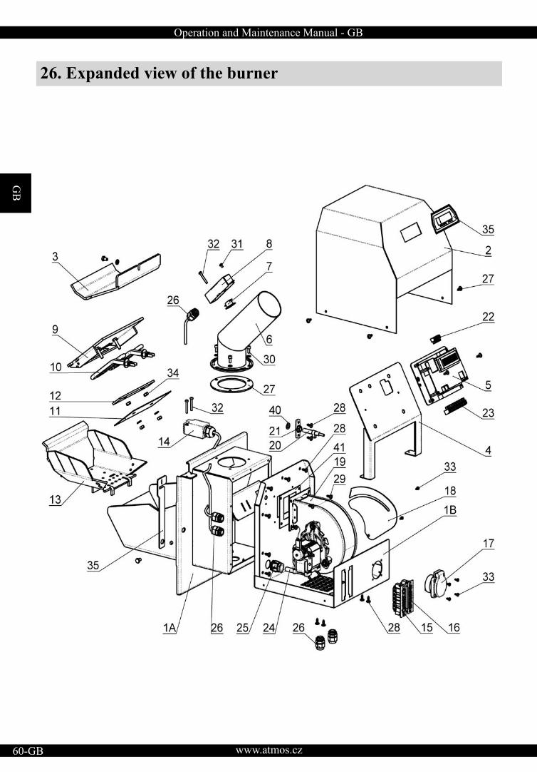
GB
www.atmos.cz60-GB
Operation and Maintenance Manual - GB
26. Expanded view of the burner
Operation and Maintenance Manual - GB
GB
www.atmos.cz GB-61
GUARANTEE TERMS
1. On condition of observance of the way of use, operation and maintenance described in the ma-nual we guarantee that the product will have the characteristics defined by the relevant technicalstandards and conditions for the whole guarantee period, namely for 24 months from acceptance by the consumer and max. 32 months from the date of sale by the manufacturer to the sales repre-sentative.
2. If the product exhibits a defect in the guarantee period that was not caused by the user, the product will be repaired free of charge for the customer within the guarantee terms.
3. The guarantee period will be extended by the time period for which the product was repaired.
4. The customer shall submit claims for guarantee repairs to the customer service.
5. The guarantee for the burner is only valid if the assembly of the burner and boiler was performed by a person trained by the manufacturer in accordance with valid standards and the operation ma-nual. A condition for acknowledgment of any guarantee is legible and complete filling-in of dataabout the company that carried out the installation on page 62. If the burner gets damaged due to inexpert damage, the resulting costs will be borne by the company that carried out the assembly.
6. The buyer has been provably instructed how to use and operate the product.
7. Requests for repairs after the expiration of the guarantee period are also directed by the customer to the customer service. In this case the costs of the repair are borne by the customer.
8. The user is obliged to observe instructions in the operation and maintenance manual. In case of non-observance of the operation and maintenance manual, careless or inexpert handling or bur-ning of prohibited fuel the guarantee becomes invalid and repairs of possible damages are paid by the customer.
9. At least once a year the burner must be completely inspected, checked and cleaned by a speciali-zed company, which will confirm all the performed work in the operation manual on page 63 andfurther.
Guarantee and after-guarantee repairs are provided by:- The company that represents the ATMOS Company in the particular country for the particular region
- The assembly company that installed the product - Jaroslav Cankař a syn ATMOS, Velenského 487, 294 21 Bělá pod Bezdězem, Czech Republic, phone +420 326 701 404
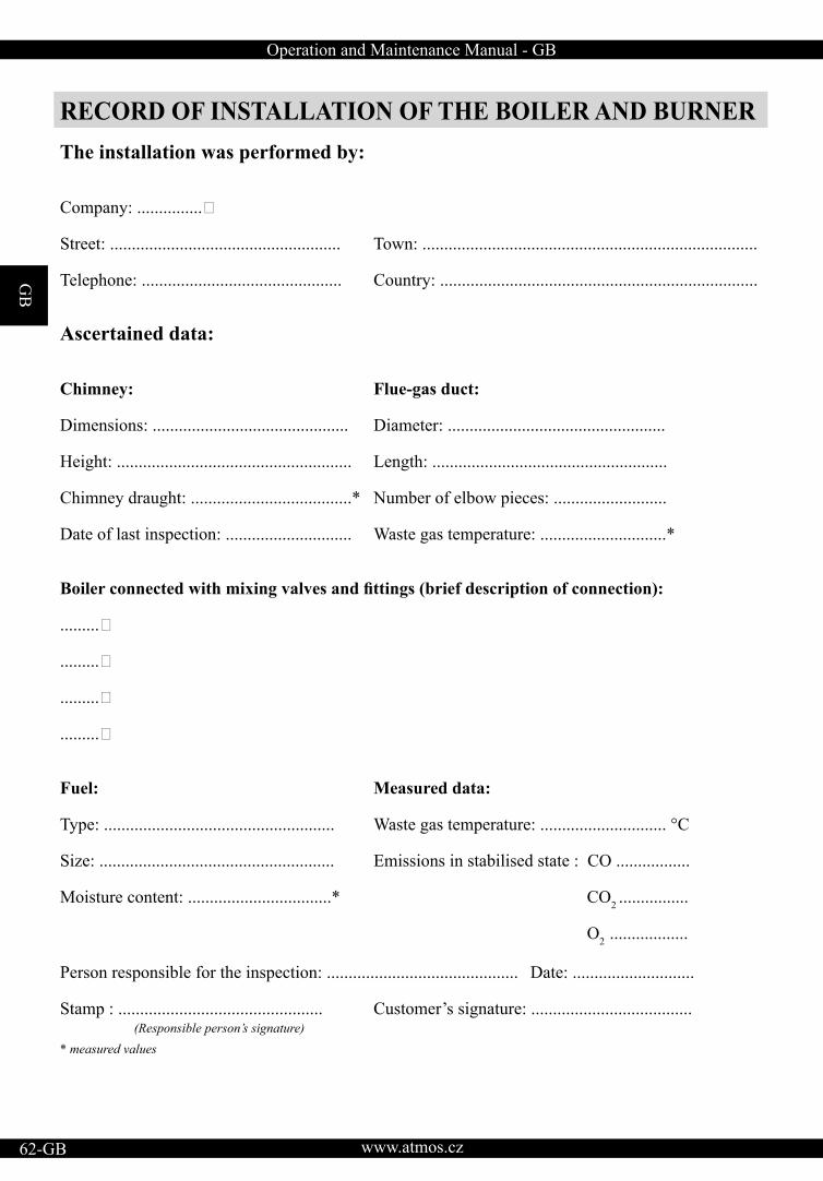
GB
www.atmos.cz62-GB
Operation and Maintenance Manual - GB
RECORD OF INSTALLATION OF THE BOILER AND BURNER The installation was performed by:
Company: ...............�
Street: ..................................................... Town: .............................................................................
Telephone: .............................................. Country: .........................................................................
Ascertained data:
Chimney: Flue-gas duct:
Dimensions: ............................................. Diameter: ..................................................
Height: ...................................................... Length: ......................................................
Chimney draught: .....................................* Number of elbow pieces: ..........................
Date of last inspection: ............................. Waste gas temperature: .............................*
Boiler connected with mixing valves and fittings (brief description of connection):
.........�
.........�
.........�
.........�
Fuel: Measured data:
Type: ..................................................... Waste gas temperature: ............................. °C Size: ...................................................... Emissions in stabilised state : CO .................
Moisture content: .................................* CO2 ................
O2 ..................
Person responsible for the inspection: ............................................ Date: ............................
Stamp : ............................................... Customer’s signature: ..................................... (Responsible person’s signature) * measured values
Operation and Maintenance Manual - GB
GB
www.atmos.cz GB-63
ANNUAL INSPECTIONS RECORDS
Date
stamp and signature
Date
stamp and signature
Date
stamp and signature
Date
stamp and signature
Date
stamp and signature
Date
stamp and signature
Date
stamp and signature
Date
stamp and signature
Date
stamp and signature
Date
stamp and signature
Date
stamp and signature
Date
stamp and signature
Date
stamp and signature
Date
stamp and signature
Date
stamp and signature
Date
stamp and signature
Date
stamp and signature
Date
stamp and signature
Date
stamp and signature
Date
stamp and signature

GB
www.atmos.cz64-GB
Operation and Maintenance Manual - GB
RECORDS OF GUARANTEE PERIODAND POST-GUARANTEE PERIOD REPAIRS
Repair: ..................�Repair: ..................�Repair: ..................�Repair: ..................�Repair: ..................�Repair: ..................�Repair: ..................�
� . repair carried out by, dateRepair: ..................�Repair: ..................�Repair: ..................�Repair: ..................�Repair: ..................�Repair: ..................�Repair: ..................�
� . repair carried out by, dateRepair: ..................�Repair: ..................�Repair: ..................�Repair: ..................�Repair: ..................�Repair: ..................�Repair: ..................�
� . repair carried out by, dateRepair: ..................�Repair: ..................�Repair: ..................�Repair: ..................�Repair: ..................�Repair: ..................�Repair: ..................�
� . repair carried out by, dateRepair: ..................�Repair: ..................�Repair: ..................�Repair: ..................�Repair: ..................�Repair: ..................�Repair: ..................�
� . repair carried out by, date