operation and maintenance manual - alamarin-jet · operation and maintenance manual...
TRANSCRIPT
Operation andmaintenance manual


Table of contentsOperation and maintenance manual
KHO/285/EN/1.2.0. iii
Table of contents1. Introduction .................................................................................................. 1
1.1. Safety precautions ............................................................................. 11.2. Symbols ............................................................................................. 1
2. The jet propulsion unit ................................................................................ 32.1. Structure ............................................................................................ 32.2. Serial number .................................................................................... 4
3. Operation ..................................................................................................... 53.1. Starting .............................................................................................. 53.2. Steering ............................................................................................. 63.3. Controlling ......................................................................................... 7
3.3.1. The positions of the reversing deflector control lever ............. 73.3.2. Using the reversing deflector ................................................. 9
3.4. Driving under difficult conditions ..................................................... 93.5. Dry running ..................................................................................... 10
4. Maintenance ............................................................................................... 114.1. Washing ........................................................................................... 114.2. Corrosion protection ........................................................................ 11
4.2.1. Changing the anodes ............................................................ 114.2.2. Touch-up painting and antifouling ........................................ 13
4.3. Bearing ............................................................................................ 144.3.1. Lubricating the front bearing ............................................... 154.3.2. Lubrication of the rear end bearing ..................................... 16
4.4. Control system ................................................................................. 184.5. Seals ................................................................................................ 194.6. Hydraulic reversing deflector control system ................................. 214.7. Raw water cooling ........................................................................... 244.8. Impeller ........................................................................................... 25
4.8.1. Checking the impeller ........................................................... 254.8.2. Removing the impeller .......................................................... 264.8.3. Installing the impeller ........................................................... 30
4.9. Intermediate shaft ........................................................................... 365. Problem situations ..................................................................................... 39
5.1. Cavitation ......................................................................................... 395.2. Ventilation ........................................................................................ 405.3. Clogged jet ...................................................................................... 41
Appendix 1. Declaration of incorporation for partially completedmachinery ....................................................................................................... 45Appendix 2. Grease recommendations ........................................................... 46Appendix 3. Oil recommendations ................................................................. 47Appendix 4. Tightening torques ..................................................................... 48Appendix 5. Test report ................................................................................. 49

WARRANTY TERMS
Alamarin-Jet Oy | Tuomisentie 16, FI-62300 Härmä, Finland | Tel +358 10 774 5260 | Fax +358 10 774 5269 | [email protected] | alamarinjet.com
Warranty for the Alamarin-Jet products is 12 months from the first sea trial. However no longer than 18 months from the date of delivery from our factory. Alamarin-Jet Warranty covers defects in Alamarin-Jet workmanship and materials for the Warranty period. Alamarin-Jet warranty terms will not cover normal part wear nor following cases with external source of issue: incorrect installation, damage caused by outside affect, vessel overloading, misuse, abnormal wear and tear, accident, improper application, improper transportation or storage, natural calamity, unsuitable water conditions, lack of maintenance or neglecting correct procedures described in Alamarin-Jet manuals. Any Alamarin-Jet product that is serviced, repaired or altered in any way by anyone other than party certified by Alamarin-Jet will not be covered by the warranty terms. Modifying or repairing Alamarin-Jet products with any other than original Alamarin-Jet parts will lead immediate invalidation of Alamarin-Jet product warranty. Alamarin-Jet Warranty terms excludes indirect costs: Crane rent, docking, warping, towing, assistance of yard crew and services, loss of profit, travel, hotel charges, daily allowances and waiting time, expenses of unauthorized repair work of Alamarin-Jet products, expenses caused by failure of the jet to other components inside or outside the vessel, damages to any third parties, injuries, or any other inconveniences. In order for warranty decision, Alamarin-Jet must receive defected parts with comprehensive failure description attached and transportation charges covered by the purchaser to Alamarin-Jet for inspection. Based on given details and inspected product, Alamarin-Jet reserves rights to define whether the case is under warranty. After inspection Alamarin-Jet will provide documented description for the customer regarding the case.
In case replacement parts are needed before Alamarin-Jet has analyzed the returned parts, purchaser buys new replacement parts. After confirming potential warranty decision, Alamarin-Jet will provide credit note covering the parts under warranty. All products and parts removed or replaced under the Warranty
shall become property of Alamarin-Jet. Alamarin-Jet reserves exclusive right for Alamarin-Jet warranty terms and no other person or distributor is authorized to modify this Warranty or give any other Warranty on behalf of Alamarin-Jet. Alamarin-Jet Oy reserves its right to change, amend, add or delete any of the Terms and Conditions without prior notice. Any disputes are to be settled according to Finnish law by arbitration in Helsinki, Finland according to the rules of the International Chamber of Commerce and in accordance with Finnish legislation of Arbitration. 2017/5/10

IntroductionOperation and maintenance manual
KHO/285/EN/1.2.0. 1
1. IntroductionCongratulations on purchasing your new Alamarin-Jet AJ 285 water jetpropulsion unit!
This manual contains important information on the operation, use andmaintenance of the unit. Please read these instructions carefully before usingthe unit. This way the unit will be safe to operate.
Please retain this manual for the duration of the product's life cycle. If you losethe manual, contact your nearest distributor for a new one. If you sell the unit,make sure to hand over this manual to the new owner.
Please contact your nearest distributor if you have any queries regarding theoperation or maintenance of the unit.
© Alamarin-Jet Oy
Tuomisentie 16FI-62300 Härmä, FinlandTelephone: +358 10 7745 260Fax: +358 10 7745 269Internet: www.alamarinjet.com
All rights reserved.
The information in this manual may not be copied, published or reproduced inany way whatsoever, or exploited for commercial purposes, without expresswritten permission from Alamarin-Jet Oy.
The information in this manual is subject to change without notice. Alamarin-Jet Oy reserves the right to modify the contents without notice.
1.1. Safety precautionsRead these instructions carefully before you operate a boat equipped with thewater jet propulsion unit or carry out any maintenance procedures. Pleasealso read the boat's manual. Always follow the instructions and the safetyprecautions below.
• Only a person with adequate training is permitted to carry out thedemanding maintenance procedures described in this manual.
• The person carrying out the procedures must always wear the appropriateprotective equipment.
• The work premises must be sufficiently large, safe and well-lit.
• The tools that are to be used must be clean and appropriate for the intendedpurpose.
1.2. SymbolsPlease refer to table 1 for a description of the symbols used in this manual.
Table 1. The symbols used in the manual
Icon DescriptionDANGER
Negligence in the performance of a procedure can cause a threatto your life.

IntroductionOperation and maintenance manual
2 KHO/285/EN/1.2.0.
Icon DescriptionWARNING
Negligence in the performance of the procedures can lead topersonal injury, breakdown of equipment, or serious malfunctionof the equipment.CAUTION
The procedure involves minor danger or a possibility of minordamage to equipment.WARRANTY
The warranty is voided if the procedure is carried out incorrectly.
NOTE
Important notice or fact.
TIP
Additional information that facilitates the performance of work ora procedure.MAINTENANCE ON LAND
The boat must be lifted out of the water for maintenance.
MAINTENANCE IN WATER
The maintenance procedure can be carried out in water.
CARRIED OUT BY ONE PERSON
One person can carry out the procedure.
CARRIED OUT BY TWO PERSONS
Two persons must carry out the procedure.
INDICATOR ARROWARROW DESCRIBING MOTION
Please note that this instruction uses the terms "jet" and "jet propulsion unit".They mainly refer to the same thing.

The jet propulsion unitOperation and maintenance manual
KHO/285/EN/1.2.0. 3
2. The jet propulsion unitThe Alamarin-Jet water jet propulsion unit (jet) is a single stage mixed flowpump, which produces a high volume flow rate and thrust with high efficiency.
The operation of the unit is based on increasing the water flow rate in thenozzle. The change in the flow rate creates a reactive force in the direction ofthe flow, which thrusts the boat forward. By changing the direction of the jetflow, the boat can be steered in the desired direction.
The jet gets its propulsion power from a petrol or diesel engine. The mostcommon way to transmit the power is through a gearbox, but a directdrive installation is also possible and functional. The greatest benefits ofa gearbox are a real neutral gear and an intake duct backflush. In bobtailinstallation, it is commendable to use a flywheel adapter provided by theengine manufacturer. This will protect the engine from mechanical damageand corrosion, for example.
2.1. StructureThe jet consists of four main parts (figure 1). These are specified in the table 2.
Figure 1. Main parts of the jet
Table 2. Purpose of the main parts of the jet
Part PurposeIntake duct (A) Leads the water from outside the boat to the intake side of
the impeller. Keeps the loss of power as small as possibleand distributes velocity evenly.
Impeller (B) Increases the water's flow rate. The impeller is rotatedby the driving motor. The nozzle converts the pressureenergy produced by the impeller into motion energy.
Steering device(C)
Changes the direction of the jet flow coming out of thenozzle, which creates the force needed for turning.
The jet propulsion unitOperation and maintenance manual
4 KHO/285/EN/1.2.0.
Part PurposeControlling device(D)
Causes the boat to reverse and stop. Lowering thereversing deflector causes the boat to reverse. Thedirection of the jet flow changes obliquely forward underthe boat, which is when the thrust is directed forward anddown.
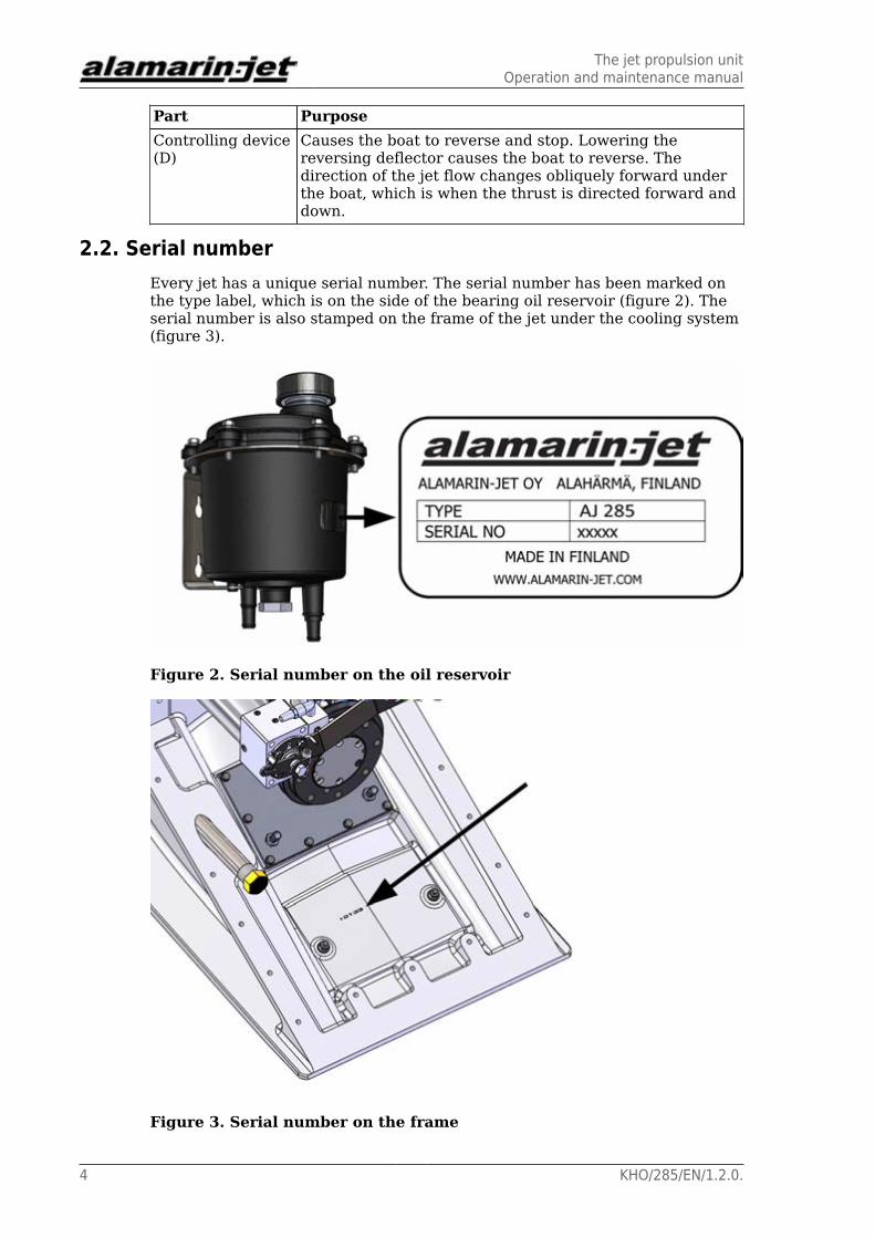
2.2. Serial numberEvery jet has a unique serial number. The serial number has been marked onthe type label, which is on the side of the bearing oil reservoir (figure 2). Theserial number is also stamped on the frame of the jet under the cooling system(figure 3).
Figure 2. Serial number on the oil reservoir
Figure 3. Serial number on the frame

OperationOperation and maintenance manual
KHO/285/EN/1.2.0. 5
3. OperationIf you have never driven a jet boat before, familiarise yourself with theseparate guide “Steering and controlling jet boats” before driving the boat forthe first time.
3.1. StartingBefore you start the engine equipped with the jet, make sure that
• the reversing deflector control lever is in centre position
• the gear is disengaged. (If the engine has no gearbox, it must be in the idleposition before you start it.)
• Note the direction of the jet’s rotation, which usually corresponds to thedirection of the engine’s rotation (counterclockwise from the rear of theboat). This is why the gear must usually be used in the "reverse" position.
The positions of the reversing deflector control lever are described in section3.3. Controlling, page 7.
Operation for the first time
CAUTION!
Before you set the boat afloat for the first time, make surethat the jet has been installed according to the installationinstructions. If you have not personally installed the jet, checkwith the boat's retailer that the jet has been installed correctly.
Correct installation helps to prevent the emergence ofunexpected fault situations which can lead to damages.
The jet does not require separate running in. However, follow the enginemanufacturer's instructions about running in during the first few drives.Ensure the functioning of the jet carefully when driving at low speeds.
DANGER!
The jet can be dangerous when running.
Do not go near the rotating parts.
Do not open the jet's inspection hatch when the engine isrunning.
When running, the jet propulsion unit sprays water backwardsat great pressure. Make sure that there is no one in the waterbehind the boat!
The intake in the bottom of the boat causes suction power atthe back of the boat when the jet propulsion unit is running.Make sure that there is no one in the water at risk of beingaffected by the intake.
When you start the engine for the first time, you may hear a jingling sound fora few minutes. This is normal and the sound will disappear when the impeller

OperationOperation and maintenance manual
6 KHO/285/EN/1.2.0.
gap sets in place. The noise from the oil pump may be loud at first but it willdisappear as the system fills up with oil.
During the first few drives, the reversing deflector's hydraulic control systemneeds more oil than usual because the hoses and the cooler are empty. Checkthe oil level and add more oil if necessary in accordance with the instructionsin section 4.3.1. Lubricating the front bearing, page 15.
NOTE!
An oil leak may pollute the environment.
Monitor the oil level and make sure that oil does not leak out.
3.2. Steering
WARRANTY!
In this section, controlling the jet boat is described in a waythat it is performed using a system that has been installed asintended by the manufacturer.
Alamarin-Jet Oy is not liable for damages which derive fromincorrect installation of the system.
Steering denotes exclusively moving the steering nozzle. Steering meanschanging the boat's bow angle.
The boat is steered by turning the steering wheel. The steering wheel ishydraulically connected to the cylinder, which moves the steering nozzle.
Figure 4. Steering device
Steering is possible only when the power of the jet flow is sufficient. This iswhy the engine must run on sufficiently high revs when steering. A suitablenumber of revolutions depends on the engine. Usually it is between 1,000 and1,500 rpm.
In sharp curves, turning the nozzle causes the boat to slow down. This isnormal and increases safety.

OperationOperation and maintenance manual
KHO/285/EN/1.2.0. 7
Turning the nozzle from one extreme position to the other takes between1 and 3 revolutions of the steering wheel, depending on the capacity of thesteering pump used.
TIP!
When the boat is not in use, it is advisable to turn the wheelall the way to the left. This will protect the cylinder rod andprevent it from collecting dirt, thus increasing the service lifeof the seals.
3.3. ControllingControlling denotes exclusively moving the reversing deflector. Controllingmeans changing the boat's driving direction (forward–astern). The reversingdeflector is moved with the lever, which is usually next to the throttle lever.The lever controls the hydraulic system mechanically (the cable operates thecylinder valve)
The reversing deflector can be lowered in front of the jet flow usinghydraulics, causing the boat to reverse (figure 5).
Figure 5. Lowering the reversing deflector
3.3.1. The positions of the reversing deflector control lever
The reversing deflector control lever can be in one of three positions: forward,rear or centre.
Forward position
When the reversing deflector control lever is in the forward position, thedeflector is not blocking the jet flow and the boat moves forward (figure 6).

OperationOperation and maintenance manual
8 KHO/285/EN/1.2.0.
Figure 6. Ahead
A Throttle leverB Control lever
Rear position
When the reversing deflector control lever is in the rear position, the deflectoris blocking the jet flow and the boat moves astern (figure 7).
Figure 7. Astern
A Throttle leverB Control lever
Centre position
The centre position of the control lever corresponds to the ”idle” position ofthe gearbox: even though the drive is on, the boat does not move. The centreposition is not absolute as it depends on the power of the jet flow. You can findthe centre position by testing during the first few driving hours.

OperationOperation and maintenance manual
KHO/285/EN/1.2.0. 9
TIP!
When the boat is not in use, it is advisable to raise thereversing deflector into the upright position. This will protectthe cylinder rod and prevent it from collecting dirt, thusincreasing the service life of the seals. For long-term storage,you can ensure that the reversing deflector stays in theupright position by tying it from the lifting loop to the stern ofthe boat.
3.3.2. Using the reversing deflector
When moving at low speeds, the reversing deflector is used to control theboat's speed. Because the engine is being run at 1,000–1,500 rpm to enhancesteering, the boat may travel faster than desired. If this is the case, thedeflector can be lowered in front of the jet flow to reduce the thrust directedtowards the driving direction. This does not affect the steerability, whichremains good.
At high speeds, the deflector is not used to reduce speed. Instead, speed iscontrolled with engine revolutions.
It is possible to turn the boat in place when the deflector is in the centreposition. When the nozzle is turned in the desired direction, the boat rotatesabout its central axis.
When reversing, steering is inversed in comparison to driving forward. Ifyou want to reverse the boat to the left, you must turn the steering wheel tothe right. A good rule to remember is that the boat's bow always turns in thesame direction as the wheel when reversing. When fast turns are needed, theengine revolutions are not reduced. Instead, the turn is performed through thecombined motion of the nozzle and the deflector.
Emergency stop
When the boat is running forwards at great speed, it is possible to stop theboat by only using the reversing deflector. When the reversing deflector islowered quickly, the boat stops in a very short distance. The emergency stop isto be used in emergencies only.
WARNING!
Alert the passengers and tell them to hold on to something ifyou are planning an emergency stop. Without being prepared,a passenger may be thrown overboard.
3.4. Driving under difficult conditionsShallow water
The jet boat can be used in very shallow water. However, note that especiallyon high revolutions, the suction power of the intake is high (figure 8).

OperationOperation and maintenance manual
10 KHO/285/EN/1.2.0.
Figure 8. Suction power of the intake
Loose objects may get sucked into the grass rake and small objects maywash through the jet. Stones may cause damage to the jet and its parts. Insandy conditions, the impeller inevitably wears. A worn impeller requiresmaintenance (section 4.8. Impeller, page 25).
Reed fields
At planing speeds, a jet boat usually crosses reed fields without difficulty. Indifficult conditions, however, clogging may be possible.
A clogged jet must be cleaned immediately (section 5.3. Clogged jet, page41).
3.5. Dry runningThe jet may be run by the engine even out of the water, because the bearingsare greased and oiled. This is a significant benefit in comparison to water-lubricated bearings, which do not sustain dry running well.
During dry runs, a temporary water inlet must be arranged for the motor seawater cycle to cool the engine.

MaintenanceOperation and maintenance manual
KHO/285/EN/1.2.0. 11
4. MaintenanceThe jet is designed and manufactured to be as simple as possible. This is whythe need for maintenance is low and maintenance can be carried out on shore.However, maintenance must be performed regularly and whenever the needarises.
Alamarin-Jet can provide you with a toolkit, available through separate order,for maintenance purposes. The toolkit includes the tools needed to performmost maintenance and repair procedures on the jet. The tools included in thetoolkit are specified in table 3.
Table 3. Toolkit
Tool Pcs SizeWrench 5 10 (0.39"), 13 (0.51"), 17 (0.67"),
19 (0.74") mmAllen wrench 4 5 (0.20"), 6 (0.24"), 8 (0.31"), 10
(0.39") mmKnife 1 -Universal pliers 1 -Feeler gauge 1 -
4.1. Washing
Washing the jet regularly removes possible salt accruals and impurities, thusreducing the risk of corrosion.
Every time you lift the jet out of the water, it is a good idea to rinse it withfresh water.
4.2. Corrosion protectionThe jet has been protected against corrosion in the manufacturing andinstallation phases. However, the protection requires regular maintenance.
4.2.1. Changing the anodes
The main raw materials used for manufacturing the jet parts are aluminium,acid-proof steel and plastic. Materials that have different electrochemicalproperties can form a galvanic couple when they are submerged in electrolyticfluid (salt water). A galvanic couple forms an electrical circuit because thematerials have different inherent voltages. This in turn leads to electronmovement and corrosion of the weaker material.
Cathodic protection is used to prevent the propagation of galvanic corrosion.Cathodic protection means introducing a third material with weakerelectrochemical properties into the same circuit.

MaintenanceOperation and maintenance manual
12 KHO/285/EN/1.2.0.
The jet is protected from galvanic corrosion with passive cathodic protection,i.e. with anodes. Every critical aluminium casting has its own anode. Thelocations of the anodes are shown in figure 9.
Figure 9. Anodes
A Steering nozzle (1 pc)B Stator (1 pc)C Reversing deflector (2 pcs)D Impeller tunnel (1 pc)E Stator, inside (1 pc)F Frame (2 pcs)G Inspection hatch (1 pc)
The functioning of the anodes is absolutely crucial to prevent corrosion. Theanodes must be replaced when they have worn down to half their original size.
Replacing the anodes:
Most of the anodes are attached with simple screws. Below you will findinstructions for changing the anodes that are attached differently.
Replacing the stator anode

MaintenanceOperation and maintenance manual
KHO/285/EN/1.2.0. 13
Figure 10. Stator anode
The stator is protected by an anode housed under a plastic plug located on thestarboard side the stator. To remove the anode, first open the arrester screw(figure 10, point A) and unscrew the plug. Now you can replace the anodelocated inside the plug. Leave the screw that holds the anode in place (figure10, point B) loose and fasten the plug into place using a sealing compound(such as Sikaflex 221). Only then attach the other end of the arrester to thestator. After this, tighten the screw that holds the anode in place.
4.2.2. Touch-up painting and antifouling
The aluminium castings have been protected with paint. Painting efficientlyprevents the propagation of various forms of corrosion, e.g. pit corrosion.
Bare aluminium, on the other hand, is liable to corrosion in difficult conditions.This is why it is important to carry out touch-up painting if paint comes looseand aluminium is exposed. Touch-up painting can be done in various ways.What is important is that the paints used are suitable for aluminium and thatthe paint manufacturer's instructions are followed during painting.
If the boat is going to be used in waterways where the growth and stickingof organisms around the boat’s bottom and the propulsion unit is heavy,the propulsion unit can be painted with antifouling paint after installation.Generally speaking, antifouling paints are based on various solublesubstances, such as copper. Because the propulsion unit is made mainly ofaluminium, copper forms a highly unfavourable galvanic couple with thepropulsion unit. In other words, the aluminium starts to corrode because itfunctions as an anode.

MaintenanceOperation and maintenance manual
14 KHO/285/EN/1.2.0.
WARNING!
Familiarise yourself with antifouling before painting thepropulsion unit with antifouling paint! Painting the propulsionunit with antifouling paint that contains copper will result inheavy corrosion and destruction of the propulsion unit. Do notuse any other antifouling paints for painting the propulsionunit except those intended for aluminium surfaces.
A boat bottom made of reinforced plastic can be painted using antifoulingpaint that contains copper. In this case, leave a 50 mm (2") unpainted areaaround the propulsion unit in the stern and on the bottom of the boat (figure11).
Figure 11. Antifouling
A Unpainted areaB Painted area
CAUTION!
Do not paint the anodes or their fastening screws.
4.3. BearingThe jet's bearing is very simple. There are bearings at both ends of the directshaft. The structure of the front bearing (figure 12, point A) is receptive toaxial pressure. It also carries the radial loads caused by the weight of theshaft and the parts attached to it. At the rear end, a grease lubricated needlebearing supports the shaft (figure 12, point B). A water-lubricated bushing canalso be used.
MaintenanceOperation and maintenance manual
KHO/285/EN/1.2.0. 15
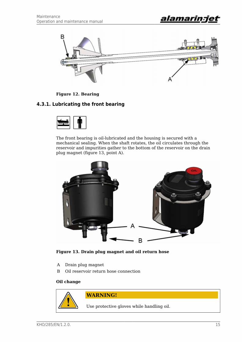
Figure 12. Bearing
4.3.1. Lubricating the front bearing
The front bearing is oil-lubricated and the housing is secured with amechanical sealing. When the shaft rotates, the oil circulates through thereservoir and impurities gather to the bottom of the reservoir on the drainplug magnet (figure 13, point A).
Figure 13. Drain plug magnet and oil return hose
A Drain plug magnetB Oil reservoir return hose connection
Oil change
WARNING!
Use protective gloves while handling oil.

MaintenanceOperation and maintenance manual
16 KHO/285/EN/1.2.0.
The front bearing oil must be changed after the first 20 hours of driving andthen after every 500 hours or once every driving season.
Before you start changing the oil, make sure you have a container for drainingthe used oil.
Changing the oil:
1. Open the reservoir cap and stir the oil inside.
Impurities are easier to remove from the reservoir when they are mixed inwith the oil.
2. Open the drain plug (figure 13, point A) and drain the oil into thecontainer.
3. Clean the plug magnet, close the drain plug and fill the reservoirwith new oil. Oil recommendations can be found in appendix 3. Oilrecommendations, page 47.
This prevents air from drifting into the system and ensures that lubricationfunctions well from the start.
4. Remove the reservoir return hose (figure 13, point B) and keep it belowthe reservoir.
This way the oil drains out from the bearing housing and the hoses andthe system fills up with new oil. The time it takes to drain the oil dependson how far the reservoir is from the bearing housing. The colour of the oilindicates whether all the old oil has drained out. The system can have amaximum volume of up to 1 L, depending on the length of the hoses.
5. Attach the oil return hose to the reservoir once the system is filled withnew oil.
6. Check the oil level from the dipstick on the reservoir cap (figure 22, pointB).
When the shaft starts to rotate, the system generates pressure into thereturn line, causing oil to start circulating in the system.
4.3.2. Lubrication of the rear end bearing
The rear end bearing is lubricated from the engine room with petroleum jelly.The external lubrication channel runs from the engine room to the stator,through which the lubricant flows into the rear bearing housing.
An automatic lubrication unit that makes sure that the rear end bearing islubricated regularly is available as an accessory.

MaintenanceOperation and maintenance manual
KHO/285/EN/1.2.0. 17
Figure 14. Automatic lubrication unit
A Oil pressure hose from thehydraulic cylinder
D Grease nipple
B Scale E Grease hose to the lubricationchannel
C Piston
Feeding
You can adjust the feed as follows:
• If the automatic lubrication unit feeds too much grease (the reservoirempties too soon), reduce the pressure by loosening the adjusting screw(figure 15).
• If the automatic lubrication unit does not feed grease to the rear bearing(cold conditions, thick grease type), increase the pressure by tightening theadjusting screw (figure 15).

MaintenanceOperation and maintenance manual
18 KHO/285/EN/1.2.0.
Figure 15. Lubricating the Rear Bearing
The amount of grease fed to the rear bearing must be 0.1 l/100 h (6 cu in/100h). The grease volume in the unit is 0.3 l (18 cu in). With these settings, thereservoir empties after 300 hours. If you notice that the reservoir emptiesmore quickly or slowly than this, adjust the pressure in the desired direction.
You can fill the reservoir by pushing grease into it with a grease gun throughthe nipple (figure 14, point D). This will cause the piston to protrude out of thereservoir.
The properties of the grease to use are described in appendix 2. Greaserecommendations, page 46.
NOTE!
Any excess grease exits the bearing housing into the water.
Only use environmentally friendly grease for lubricating thebearing.
If there is no automatic lubrication unit installed into the system, there is anipple at the end of the lubrication hose, through which grease can be pumpedto the rear bearing. 0.5 dl (6 cu in) of grease should be added every 50 hrs.
4.4. Control system
The joints and shaft bushings that belong to the control systems are essentiallymaintenance-free, but lubrication prolongs their operating life. Locations
MaintenanceOperation and maintenance manual
KHO/285/EN/1.2.0. 19
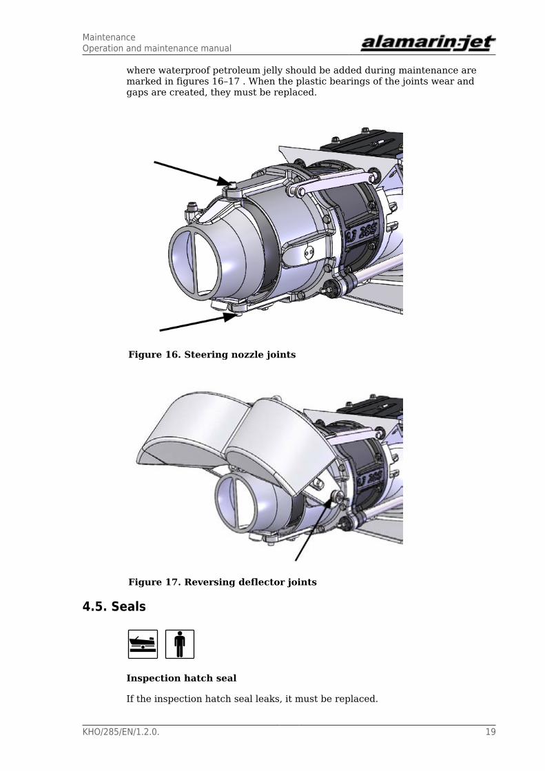
where waterproof petroleum jelly should be added during maintenance aremarked in figures 16–17 . When the plastic bearings of the joints wear andgaps are created, they must be replaced.
Figure 16. Steering nozzle joints
Figure 17. Reversing deflector joints
4.5. Seals
Inspection hatch seal
If the inspection hatch seal leaks, it must be replaced.

MaintenanceOperation and maintenance manual
20 KHO/285/EN/1.2.0.
Figure 18. Inspection hatch seal
If the inspection hatch seal leaks, it will cause ventilation or water leakage inthe engine room if the inspection hatch is inside the engine room (see section5.2. Ventilation, page 40).
Control rod seals
There are threaded sleeves equipped with seals at the rear ends of the controlrods (figure 19). The seals can be replaced without removing the cylinders.
Figure 19. Control rod seals
Replacing the seals:
Unscrew the sleeve by turning it from the holes on the front surface of thesleeve.
We recommend replacing the sleeve along with the seal. Apply some sealingcompound to the thread and screw the sleeve into place.

MaintenanceOperation and maintenance manual
KHO/285/EN/1.2.0. 21
CAUTION!
If water gathers in the bilge, the cause for this must bedetermined immediately. Any possible leaks must be repairedimmediately. Water can damage e.g. the starter motor.
4.6. Hydraulic reversing deflector control systemFor controlling the reversing deflector, the jet has a hydraulic cylinder which isoperated mechanically with a cable. The cable (figure 20, point B) operates thevalve regulator (point A). The cylinder gets its power from the pump which hasbeen integrated in the propulsion unit.
Figure 20. Hydraulic cylinder
In a stock delivery, the system does not include a control lever or a cable, sotheir type varies depending on the boat manufacturer. However, the differenttypes of systems have the following things in common:
• The operation of the deflector is always separate from the throttle and thegearbox.
• The stroke length of the cylinder is always the same.
• The incoming direction of the cable can be chosen freely.
The oil circulating in the system must be cooled down in order to preventexcessive heating. This is done with a heat exchanger, which is integrated intothe frame of the propulsion unit (figure 21).
WARRANTY!
If the oil in the system is not cooled, the manufacturer is notresponsible for possible damages which derive directly orindirectly from the oil overheating.
If the valve regulator is removed, the cylinder must be readjusted. Theadjustment instructions can be found in the Repair manual.
MaintenanceOperation and maintenance manual
22 KHO/285/EN/1.2.0.
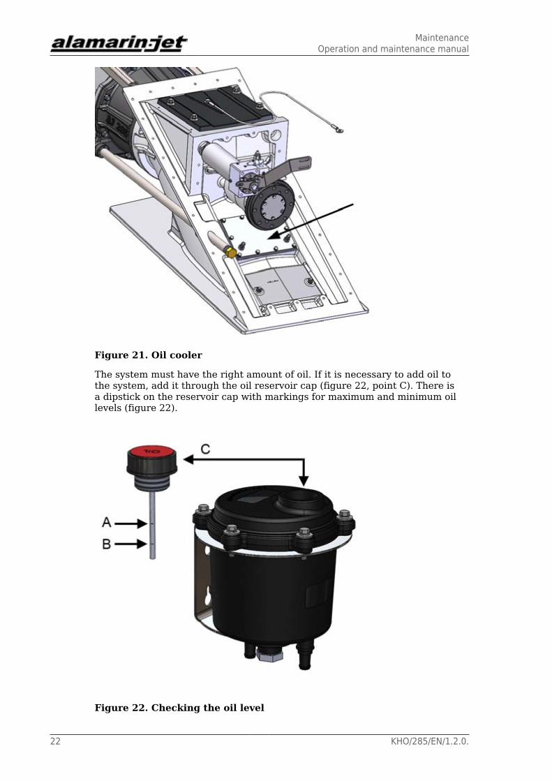
Figure 21. Oil cooler
The system must have the right amount of oil. If it is necessary to add oil tothe system, add it through the oil reservoir cap (figure 22, point C). There isa dipstick on the reservoir cap with markings for maximum and minimum oillevels (figure 22).
Figure 22. Checking the oil level

MaintenanceOperation and maintenance manual
KHO/285/EN/1.2.0. 23
A Maximum levelB Minimum levelC Cap
Note that the oil must be changed once every driving season. The type of oil touse is described in appendix 3. Oil recommendations, page 47.
Amount of oil in the hydraulic system and the front bearing
Hydraulics: 1.3–1.7 LFront bearing: 0.9–1.2 L
Replacing the oil filter
The oil filter in the oil reservoir must be replaced after every 500 operatinghours.
1. Open the six cover screws (figure 23)
Figure 23. Oil reservoir cover screws
The filter is located under the cover and has a spring on top of it thatkeeps the filter in place (figure 24).
MaintenanceOperation and maintenance manual
24 KHO/285/EN/1.2.0.
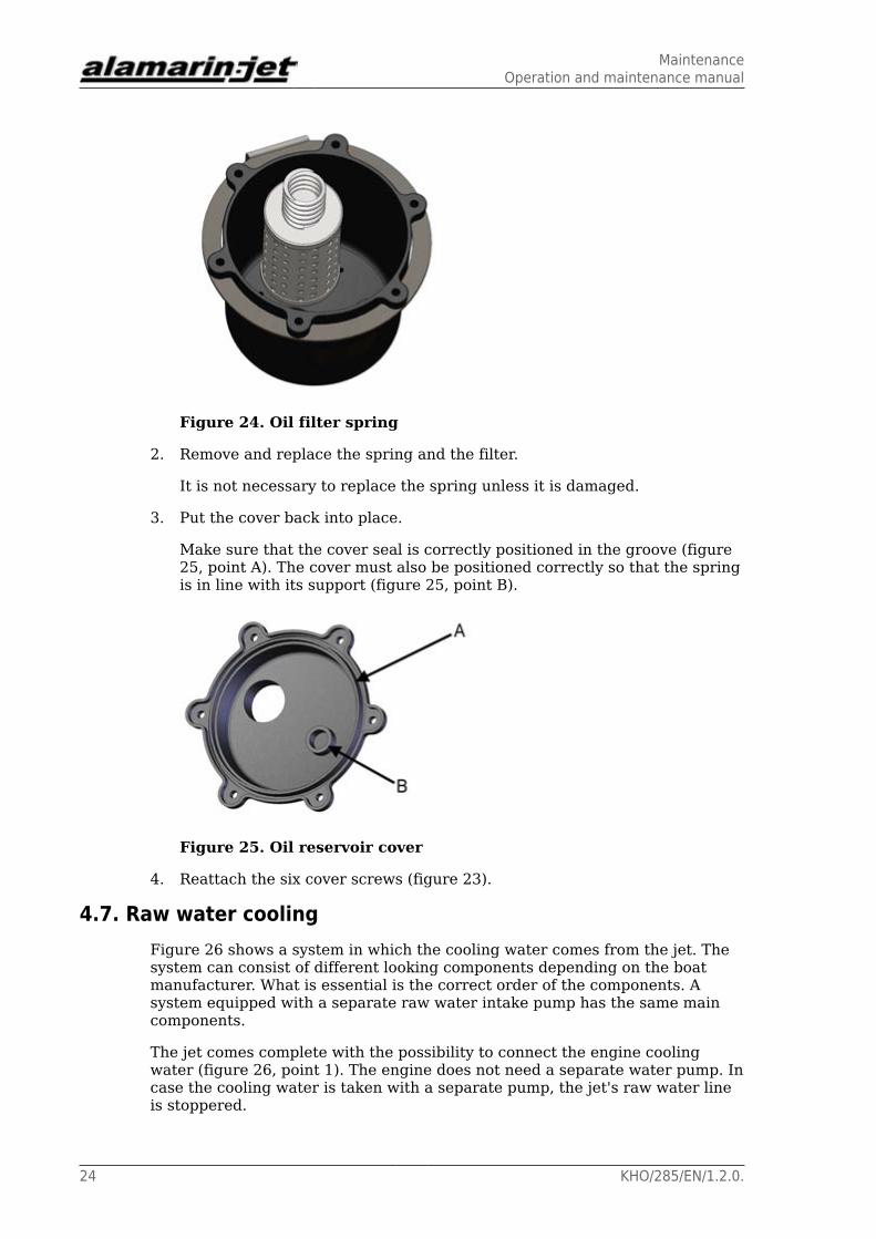
Figure 24. Oil filter spring
2. Remove and replace the spring and the filter.
It is not necessary to replace the spring unless it is damaged.
3. Put the cover back into place.
Make sure that the cover seal is correctly positioned in the groove (figure25, point A). The cover must also be positioned correctly so that the springis in line with its support (figure 25, point B).
Figure 25. Oil reservoir cover
4. Reattach the six cover screws (figure 23).
4.7. Raw water coolingFigure 26 shows a system in which the cooling water comes from the jet. Thesystem can consist of different looking components depending on the boatmanufacturer. What is essential is the correct order of the components. Asystem equipped with a separate raw water intake pump has the same maincomponents.
The jet comes complete with the possibility to connect the engine coolingwater (figure 26, point 1). The engine does not need a separate water pump. Incase the cooling water is taken with a separate pump, the jet's raw water lineis stoppered.

MaintenanceOperation and maintenance manual
KHO/285/EN/1.2.0. 25
At the beginning of the line, there must be a tap with which the line can beshut temporarily, such as during cleaning of the filter or other maintenance.The raw water line requires no other separate maintenance procedures.
Figure 26. Raw water cooling
1 Raw water connector2 Tap3 Filter4 Input for the engine
4.8. ImpellerDepending on driving conditions, the impeller will wear down, causing a gapto develop between the tunnel wall and the tip of the impeller blade. The gapshould be as small as possible to achieve maximum efficiency. (The factoryinstallation gap is 0.4 mm (approx. 0.016") when the stator centres the shaft).When the gap expands too much, the jet's performance decreases.
The impeller usually wears on the outer edge of the blades. The impelleroperates in a cone-shaped space and its position can be adjusted in thedirection of the shaft in accordance with the blade wear.
The longitudinal position of the impeller in the tunnel reveals its powerdemand. The deeper the impeller sits, the less power it takes from the engine,because the diameter of the impeller is smaller. The pitch and the length andnumber of blades naturally also affect the power demand.
By adjusting the impeller, its operating life can be prolonged considerably. Theadjustment of the impeller should be done whenever it is necessary, but checksmust be carried out at least once a year. The impeller is adjusted by removingthe impeller and then reinstalling it.
4.8.1. Checking the impeller
The condition of the front edge of the impeller blades is important. A damagedfront edge causes cavitation.
WARNING!
The impeller blade edges can be sharp and cut your hands.Protect your hands with protective gloves before you removethe impeller.

MaintenanceOperation and maintenance manual
26 KHO/285/EN/1.2.0.
The front edge can be repaired by carefully hammering the marks causedby bigger stones and grinding them smooth. The front edge must also besharpened, not sharp enough to cut, but so that it is no thicker than 1 mm(approx. 0.04").
You can also return the impeller to the factory for checking and repairing.
If you suspect that there is a malfunction in the impeller, do as follows:
1. Shut down the engine and open the inspection hatch.
2. Check that there is no blockage in the intake duct.
3. Check the impeller visually. Notice especially the gap between the outeredge of the blade and the tunnel wall.
If there is no apparent fault, do as follows:
1. Lift the boat out of the water.
2. Remove the impeller (section 4.8.2. Removing the impeller, page 26).
3. Check the impeller more closely.
Contact the importer or the manufacturer if necessary and ask foradditional instructions.
4.8.2. Removing the impeller
Before the impeller can be removed, the reversing deflector, the steeringnozzle and the stator must be removed.
Removing the impeller:
1. Open the screws indicated by arrows in figure 27 .
WARNING!
Make sure that the reversing deflector is not accidentallylowered. This may result in serious injury!
Lower the reversing deflector past the steering nozzle. The steering nozzlemust be centred when the reversing deflector is lowered.
WARNING!
The reversing deflector must not be turned by force fromthe outside while it is connected to a hydraulic cylinder.
MaintenanceOperation and maintenance manual
KHO/285/EN/1.2.0. 27
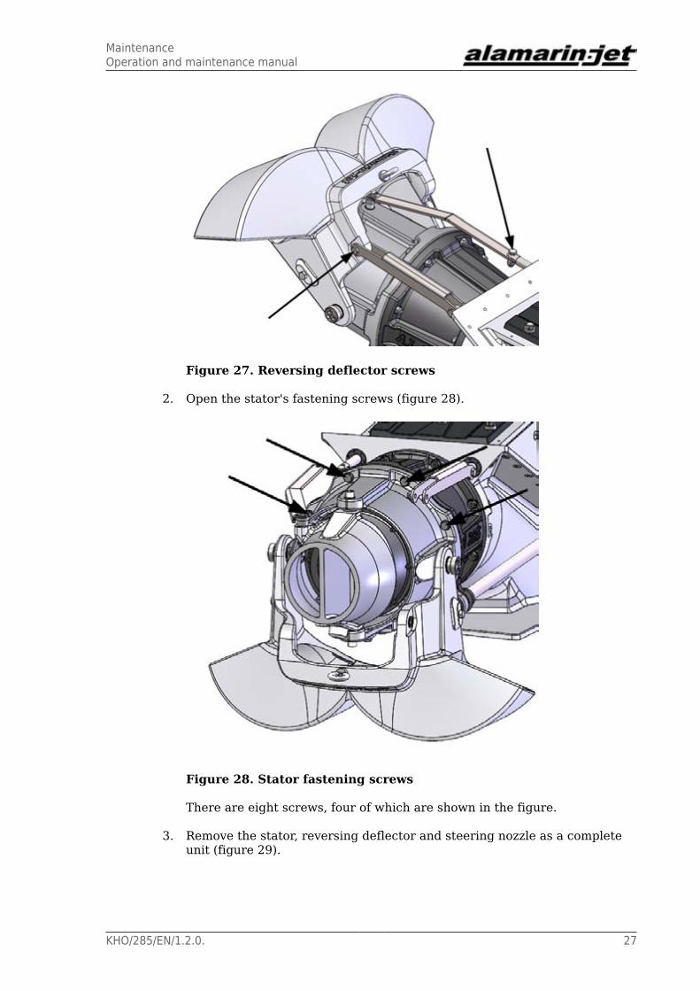
Figure 27. Reversing deflector screws
2. Open the stator's fastening screws (figure 28).
Figure 28. Stator fastening screws
There are eight screws, four of which are shown in the figure.
3. Remove the stator, reversing deflector and steering nozzle as a completeunit (figure 29).

MaintenanceOperation and maintenance manual
28 KHO/285/EN/1.2.0.
Figure 29. Removing the stator, reversing deflector and steeringnozzle
The impeller is connected to the shaft either with a mounting cone or alocking plate attached to the end of the shaft. The impeller connectionmethod depends on the model of the impeller. Instructions for removingthe impeller are provided below for both connection methods.
Mounting cone
4. Loosen the impeller fastening screws (figure 30, point A).

MaintenanceOperation and maintenance manual
KHO/285/EN/1.2.0. 29
Figure 30. Impeller fastening screws, mounting cone
5. Remove one screw completely and screw it into the threaded hole in theplastic mounting cone (figure 30, point B).
When you tighten the screw in the threaded hole, the mounting cone isreleased and the impeller can be pulled off the shaft. If the adapter is verytight, use multiple screws to release it.
Locking plate
4. Unscrew the screw located at the end of the shaft (figure 31, point A) andremove the locking plate (figure 31, point B).
MaintenanceOperation and maintenance manual
30 KHO/285/EN/1.2.0.
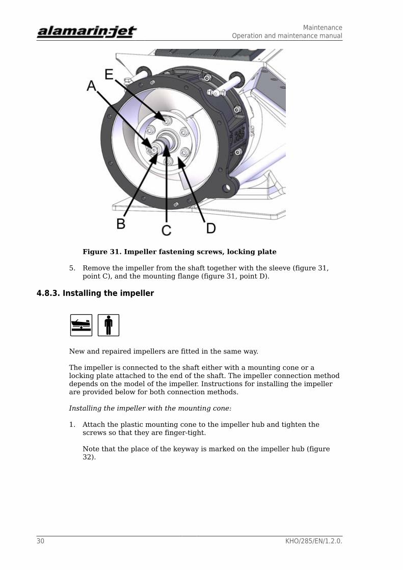
Figure 31. Impeller fastening screws, locking plate
5. Remove the impeller from the shaft together with the sleeve (figure 31,point C), and the mounting flange (figure 31, point D).
4.8.3. Installing the impeller
New and repaired impellers are fitted in the same way.
The impeller is connected to the shaft either with a mounting cone or alocking plate attached to the end of the shaft. The impeller connection methoddepends on the model of the impeller. Instructions for installing the impellerare provided below for both connection methods.
Installing the impeller with the mounting cone:
1. Attach the plastic mounting cone to the impeller hub and tighten thescrews so that they are finger-tight.
Note that the place of the keyway is marked on the impeller hub (figure32).
MaintenanceOperation and maintenance manual
KHO/285/EN/1.2.0. 31
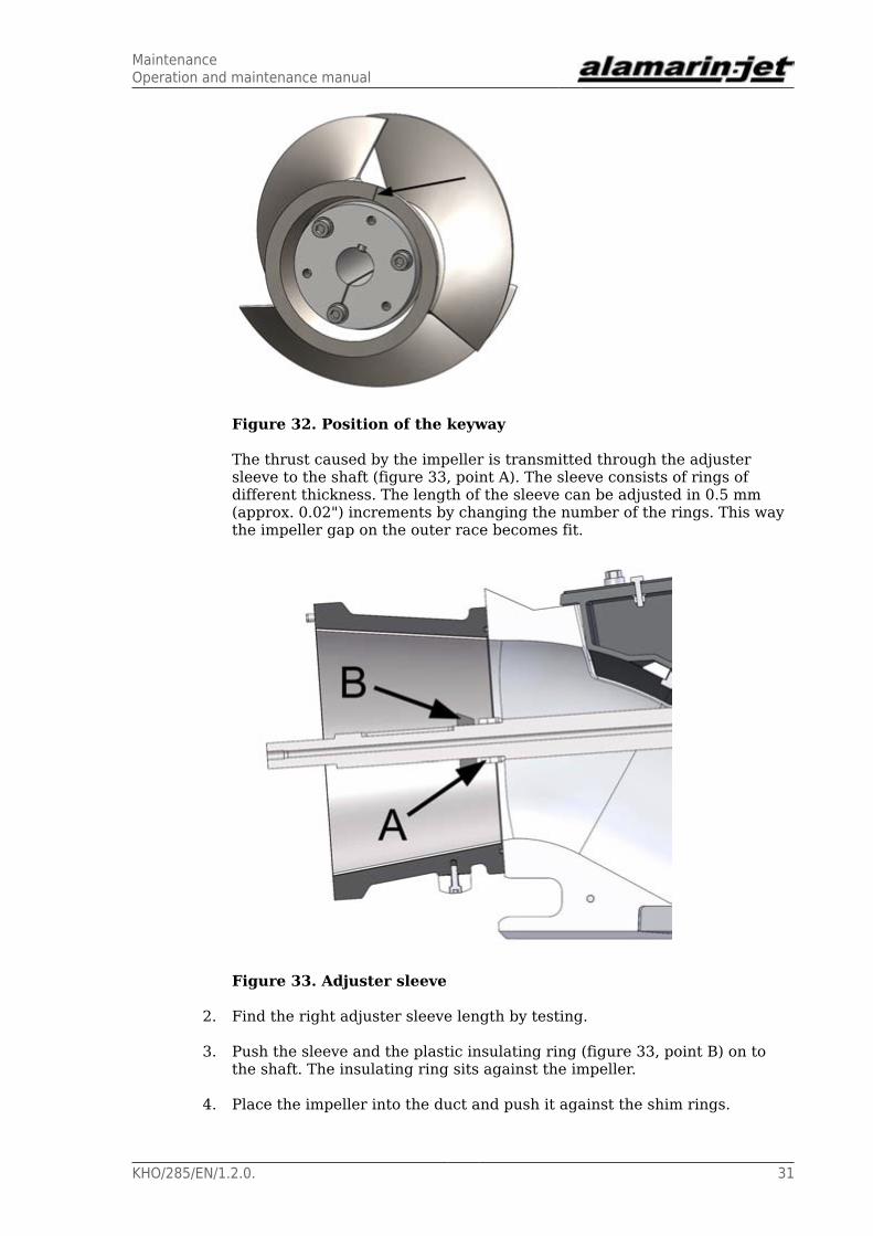
Figure 32. Position of the keyway
The thrust caused by the impeller is transmitted through the adjustersleeve to the shaft (figure 33, point A). The sleeve consists of rings ofdifferent thickness. The length of the sleeve can be adjusted in 0.5 mm(approx. 0.02") increments by changing the number of the rings. This waythe impeller gap on the outer race becomes fit.
Figure 33. Adjuster sleeve
2. Find the right adjuster sleeve length by testing.
3. Push the sleeve and the plastic insulating ring (figure 33, point B) on tothe shaft. The insulating ring sits against the impeller.
4. Place the impeller into the duct and push it against the shim rings.

MaintenanceOperation and maintenance manual
32 KHO/285/EN/1.2.0.
At this point the screws of the plastic mounting cone must be finger-tight.
5. Measure the gap on the impeller outer race.
If the front surface of the impeller hub does not reach the shim rings, addmore shim rings.
The optimal gap is 0.8–1.2 mm (approx. 0.031–0.047") at the upper partof the duct. When you measure the gap, note that the shaft is not centredwhen the stator is removed, but the shaft's rear end hangs low and thewhole gap is visible in the upper part of the duct.
CAUTION!
If the gap is too big, it will cause loss of power and reduceperformance.
6. Once you have found the right adjuster sleeve length, place the key in theshaft keyway (figure 34) and push the impeller on to the shaft against theisolation ring.
Figure 34. Keyway
7. Tighten the impeller fastening screws evenly in a crosswise sequence.
The tightening torque is 20 Nm.
While tightening, the impeller moves back a bit and a small gap developson the front. The gap will disappear when the impeller is being loaded.
8. Install the stator and the steering nozzle in place in reverse order to thatwhen removing it (section 4.8.2. Removing the impeller, page 26).
The tightening torque of the M10 screws is 46 Nm.

MaintenanceOperation and maintenance manual
KHO/285/EN/1.2.0. 33
Installing the impeller with the locking plate:
1. If the impeller mounting flange was detached from the impeller, re-attachit.
2. Lubricate the flange seals with waterproof petroleum jelly (such as ShellGadus S2 V220AC or similar) and push the sleeve into place.
Note the position of the keyway, which is indicated on the impeller hub(figure 32). Apply thread locking compound (such as Loctite 242) to thescrews and tighten them to 85 Nm.
Figure 35. Position of the keyway
The thrust caused by the impeller is transmitted through the adjustersleeve to the shaft (figure 33, point A). The sleeve consists of rings ofdifferent thickness. The length of the sleeve can be adjusted in 0.5 mm(approx. 0.02") increments by changing the number of the rings. This waythe impeller gap on the outer race becomes fit.
MaintenanceOperation and maintenance manual
34 KHO/285/EN/1.2.0.
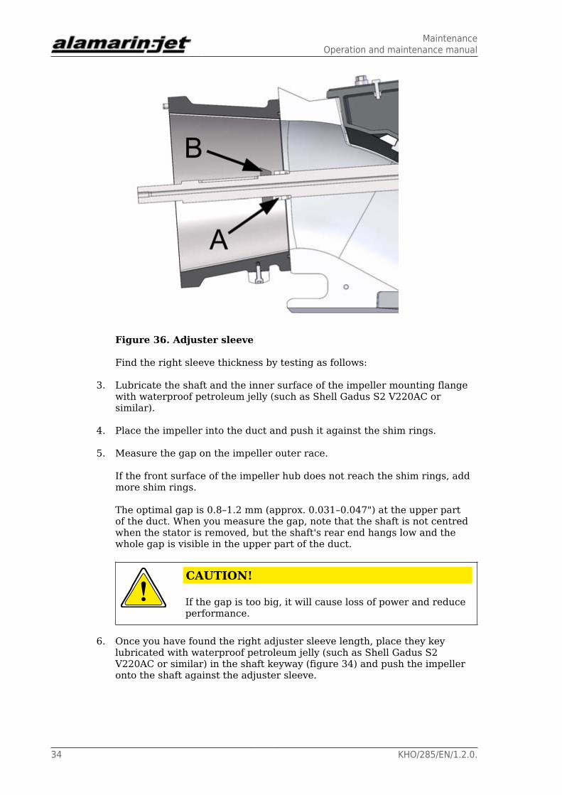
Figure 36. Adjuster sleeve
Find the right sleeve thickness by testing as follows:
3. Lubricate the shaft and the inner surface of the impeller mounting flangewith waterproof petroleum jelly (such as Shell Gadus S2 V220AC orsimilar).
4. Place the impeller into the duct and push it against the shim rings.
5. Measure the gap on the impeller outer race.
If the front surface of the impeller hub does not reach the shim rings, addmore shim rings.
The optimal gap is 0.8–1.2 mm (approx. 0.031–0.047") at the upper partof the duct. When you measure the gap, note that the shaft is not centredwhen the stator is removed, but the shaft's rear end hangs low and thewhole gap is visible in the upper part of the duct.
CAUTION!
If the gap is too big, it will cause loss of power and reduceperformance.
6. Once you have found the right adjuster sleeve length, place they keylubricated with waterproof petroleum jelly (such as Shell Gadus S2V220AC or similar) in the shaft keyway (figure 34) and push the impelleronto the shaft against the adjuster sleeve.

MaintenanceOperation and maintenance manual
KHO/285/EN/1.2.0. 35
Figure 37. Keyway
If you adjusted the impeller during periodical maintenance and had toremove shim rings due to the impeller having worn down, do not throwaway the shim rings. They are placed between the impeller and the shaftsleeve (figure 38). When installing a new impeller with a larger diameter,shim rings are moved from the back of the impeller to the front (figure 39).
Figure 38. The impeller movesforward (wearing/gap needs tobe reduced)
Figure 39. The impeller movesbackward (new impeller/gapneeds to increased)
7. Lubricate the the inner surface of the sleeve to be placed at the end of theshaft with waterproof petroleum jelly (such as Shell Gadus S2 V220AC orsimilar).
MaintenanceOperation and maintenance manual
36 KHO/285/EN/1.2.0.
8. Place the o-ring on to the shaft against the shoulder (figure 40, point A)and the shim rings against the rear surface of the impeller.
9. Push the sleeve on to the shaft.
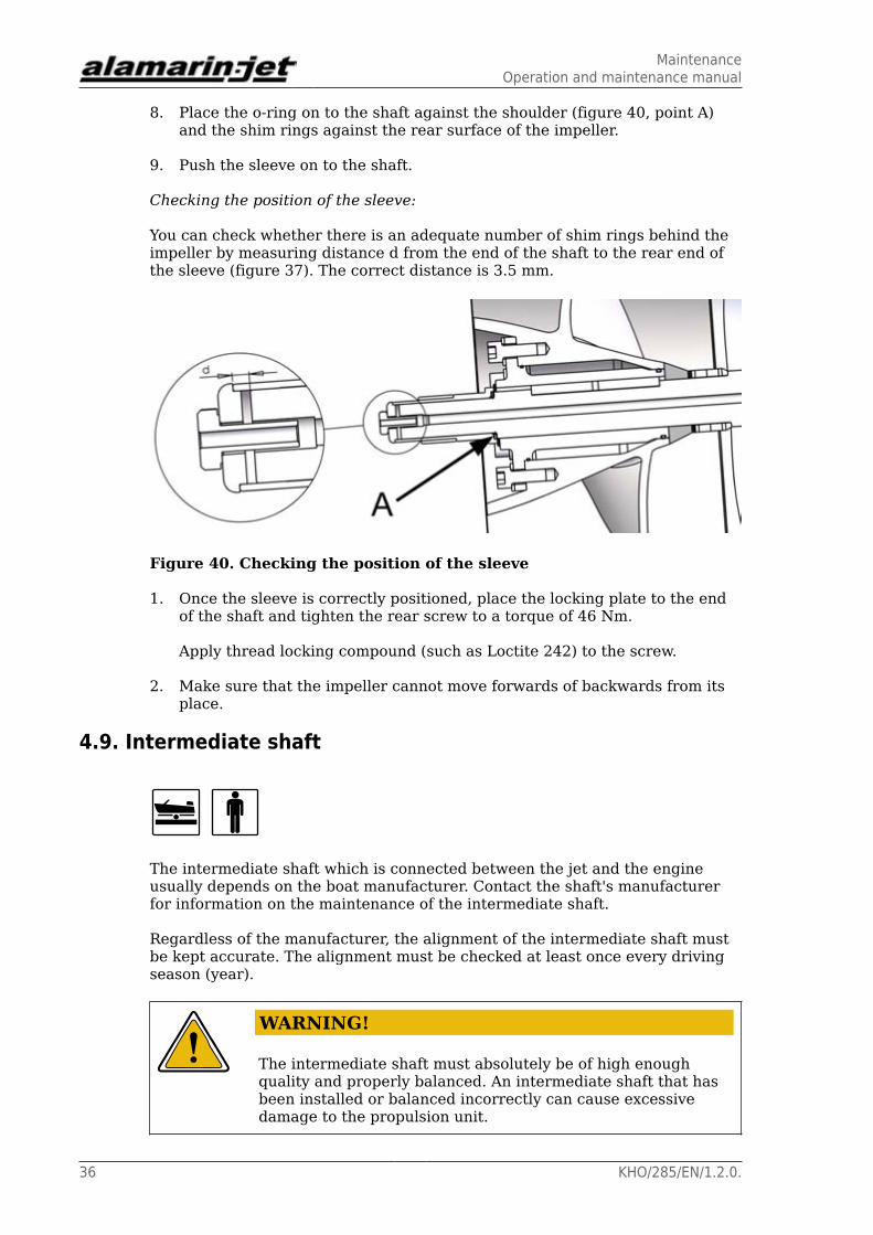
Checking the position of the sleeve:
You can check whether there is an adequate number of shim rings behind theimpeller by measuring distance d from the end of the shaft to the rear end ofthe sleeve (figure 37). The correct distance is 3.5 mm.
Figure 40. Checking the position of the sleeve
1. Once the sleeve is correctly positioned, place the locking plate to the endof the shaft and tighten the rear screw to a torque of 46 Nm.
Apply thread locking compound (such as Loctite 242) to the screw.
2. Make sure that the impeller cannot move forwards of backwards from itsplace.
4.9. Intermediate shaft
The intermediate shaft which is connected between the jet and the engineusually depends on the boat manufacturer. Contact the shaft's manufacturerfor information on the maintenance of the intermediate shaft.
Regardless of the manufacturer, the alignment of the intermediate shaft mustbe kept accurate. The alignment must be checked at least once every drivingseason (year).
WARNING!
The intermediate shaft must absolutely be of high enoughquality and properly balanced. An intermediate shaft that hasbeen installed or balanced incorrectly can cause excessivedamage to the propulsion unit.

MaintenanceOperation and maintenance manual
KHO/285/EN/1.2.0. 37
WARRANTY!
If an intermediate shaft that has been installed or balancedincorrectly causes damage, this will not be covered by thewarranty.

MaintenanceOperation and maintenance manual
38 KHO/285/EN/1.2.0.

Problem situationsOperation and maintenance manual
KHO/285/EN/1.2.0. 39
5. Problem situations5.1. Cavitation
The most common malfunction in water jet propulsion units manifests ascavitation. Cavitation is a phenomenon in which the water pressure decreaseslocally to such an extent that water vaporises on the surface of the impellerblade, creating steam bubbles. The bubbles move on the surface of the bladeand when they reach a higher pressure area they collapse.
Signs of cavitation are engine overdrive and stopping of thrust, and it canoften be heard as a thundering sound.
Cavitation reduces performance considerably and damages the impeller.Any factor that hinders the flow of water in the jet increases the chance ofcavitation. Usually the cause is the reduction of pressure in the whole intakeduct caused by a blockage.
If cavitation is apparent or the boat runs slowly even though the engine runson high revolutions, investigate the cause.
Checking the causes for cavitation:
1. Open the inspection hatch (figure 41).
Figure 41. Opened inspection hatch
2. Check the grass rake (figure 42).
Problem situationsOperation and maintenance manual
40 KHO/285/EN/1.2.0.
Make sure that grass, reed, plastic, stone or some other extraneous objectis not clogging the grass rake. Remove any possible blockages.
Figure 42. Checking the grass rake for blockages
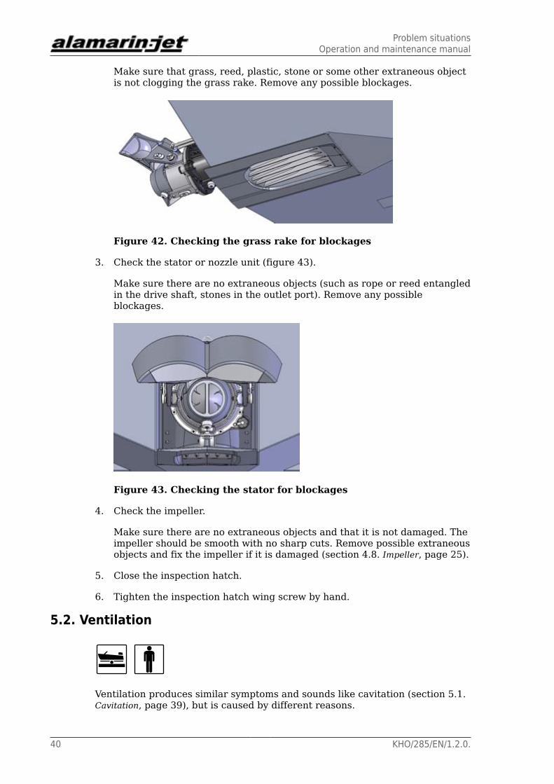
3. Check the stator or nozzle unit (figure 43).
Make sure there are no extraneous objects (such as rope or reed entangledin the drive shaft, stones in the outlet port). Remove any possibleblockages.
Figure 43. Checking the stator for blockages
4. Check the impeller.
Make sure there are no extraneous objects and that it is not damaged. Theimpeller should be smooth with no sharp cuts. Remove possible extraneousobjects and fix the impeller if it is damaged (section 4.8. Impeller, page 25).
5. Close the inspection hatch.
6. Tighten the inspection hatch wing screw by hand.
5.2. Ventilation
Ventilation produces similar symptoms and sounds like cavitation (section 5.1.Cavitation, page 39), but is caused by different reasons.

Problem situationsOperation and maintenance manual
KHO/285/EN/1.2.0. 41
Ventilation is created when air gets into the intake duct. The air causes theimpeller to lose grip and the thrust weakens.
Ventilation can be caused by the following, for example:
• The inspection hatch cover is open or the seal is damaged.
Close the inspection hatch if it is open. Change the seal if it is damaged(section 4.5. Seals, page 19).
• The installation height of the jet is wrong and air is allowed to pass along thesurface of the cavitation plate into the intake duct.
In this case the jet must be reinstalled. Consult the boat's retailer.
• During installation, places accordant with the instructions have not beensealed.
In this case, the sealing must be done again. Consult the boat's retailer.
5.3. Clogged jetDriving among water plants or in ice sludge can clog the jet. If this happens,the blockage can stop the boat from moving.
With these simple instructions it is possible practically without exception toclean very difficult blockages from the jet. Unlike with other propulsion units,in boats equipped with a jet the engine stops very rarely as a result of a waterplant blockage. However, ice sludge can clog the jet so badly that the blockagecannot be removed without lifting the boat out of the water.
Boats equipped with a gearbox
In boats equipped with a gearbox, cleaning the jet is easy because in reversegear a back flow is created in the intake duct.
Cleaning the jet:
1. Put the gear in reverse.
2. Use some acceleration to detach the blockage.
WARNING!
The jet is designed to run in reverse only for one minute at atime and at under 2,000 rpm. This is usually enough to clearthe blockage.
Too heavy a load in reverse gear can lead to jamming of theimpeller or breaking down of hydraulics.
Boats without a gearbox
Problem situationsOperation and maintenance manual
42 KHO/285/EN/1.2.0.
If the boat has no gearbox, cleaning the jet may require several phases.
Cleaning the jet:
1. Stop the engine.
This usually helps drop any extraneous objects from the grass rake.
2. Let the engine run on high revolutions for a few times.
This often sucks the extraneous objects through the jet and cleans it.
3. If the boat is moving ahead, raise the speed of the boat as high as possibleand then shut down the engine.
The speed of the boat often sweeps the grass rake clean.
4. Drive the boat in reverse as fast as possible. As the boat moves astern,shut down the engine and move the deflector control lever to the forwardposition.
This causes water to flow backwards through the jet and usually opens allkinds of blockages.
Difficult blockages
If the aforementioned measures do not remove the blockage, you can locatethe blockage through the jet's inspection hatch and remove it manually.
Removing a blockage through the inspection hatch:
1. Open the inspection hatch (figure 44).
Problem situationsOperation and maintenance manual
KHO/285/EN/1.2.0. 43
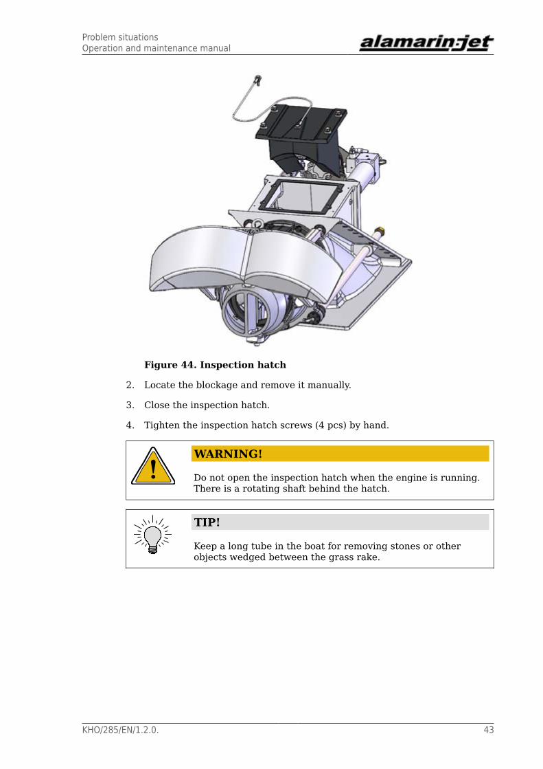
Figure 44. Inspection hatch
2. Locate the blockage and remove it manually.
3. Close the inspection hatch.
4. Tighten the inspection hatch screws (4 pcs) by hand.
WARNING!
Do not open the inspection hatch when the engine is running.There is a rotating shaft behind the hatch.
TIP!
Keep a long tube in the boat for removing stones or otherobjects wedged between the grass rake.
Problem situationsOperation and maintenance manual
44 KHO/285/EN/1.2.0.
Declaration of incorporation for partially completed machineryOperation and maintenance manual
KHO/285/EN/1.2.0. 45
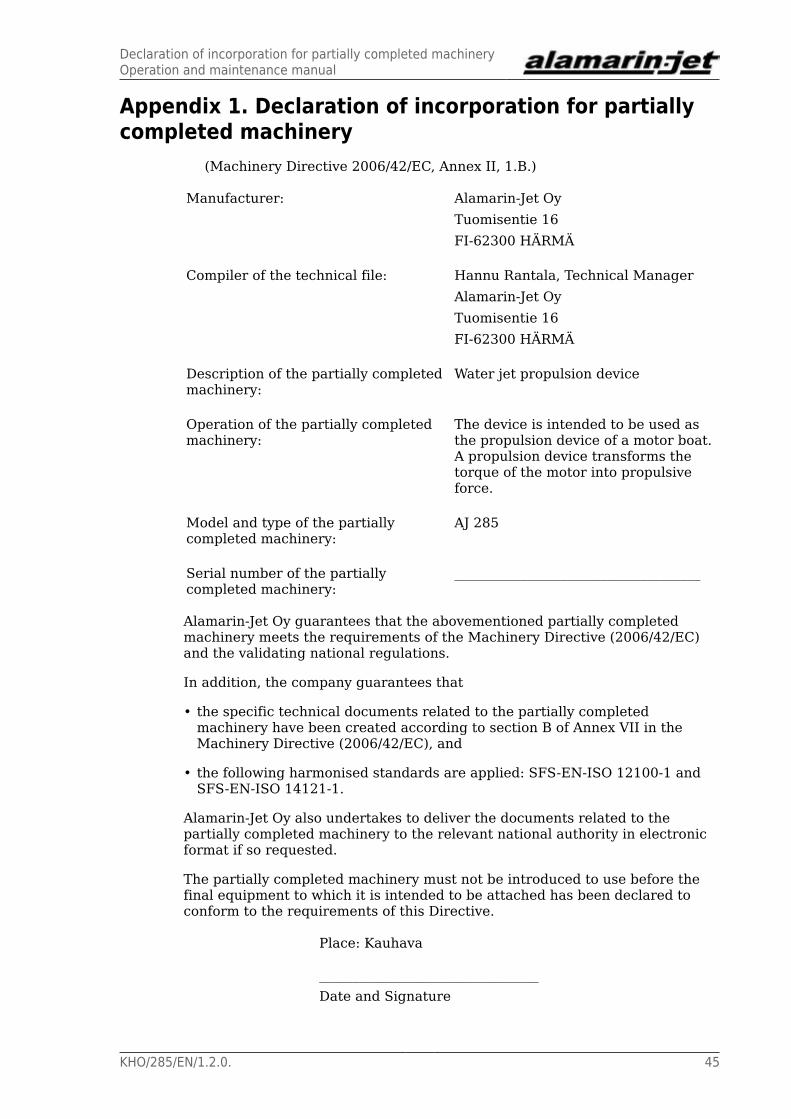
Appendix 1. Declaration of incorporation for partiallycompleted machinery
(Machinery Directive 2006/42/EC, Annex II, 1.B.)
Manufacturer: Alamarin-Jet OyTuomisentie 16FI-62300 HÄRMÄ
Compiler of the technical file: Hannu Rantala, Technical ManagerAlamarin-Jet OyTuomisentie 16FI-62300 HÄRMÄ
Description of the partially completedmachinery:
Water jet propulsion device
Operation of the partially completedmachinery:
The device is intended to be used asthe propulsion device of a motor boat.A propulsion device transforms thetorque of the motor into propulsiveforce.
Model and type of the partiallycompleted machinery:
AJ 285
Serial number of the partiallycompleted machinery:
_____________________________________
Alamarin-Jet Oy guarantees that the abovementioned partially completedmachinery meets the requirements of the Machinery Directive (2006/42/EC)and the validating national regulations.
In addition, the company guarantees that
• the specific technical documents related to the partially completedmachinery have been created according to section B of Annex VII in theMachinery Directive (2006/42/EC), and
• the following harmonised standards are applied: SFS-EN-ISO 12100-1 andSFS-EN-ISO 14121-1.
Alamarin-Jet Oy also undertakes to deliver the documents related to thepartially completed machinery to the relevant national authority in electronicformat if so requested.
The partially completed machinery must not be introduced to use before thefinal equipment to which it is intended to be attached has been declared toconform to the requirements of this Directive.
Place: Kauhava
_________________________________Date and Signature

Grease recommendationsOperation and maintenance manual
46 KHO/285/EN/1.2.0.
Appendix 2. Grease recommendationsThe grease used for lubricating the propulsion unit bearing must meet thefollowing requirements:
• lithium soap and a thickener with EP additives
• mineral oil as a base oil
• NLGI class 2
• operating temperature range -25 to 130°C (-13–266 °F)
• continuous operating temperature min. 75 °C (167 °F)
Recommended grease brands:
• Würth Multi-Purpose Grease III
• FAG Multi2
• FAG Load 220
• Mobil XHP 222
• Neste Allrex EP2
• Shell Retinax Grease EP2
A grease that has equivalent properties to those mentioned above can also beused for lubrication.
Oil recommendationsOperation and maintenance manual
KHO/285/EN/1.2.0. 47
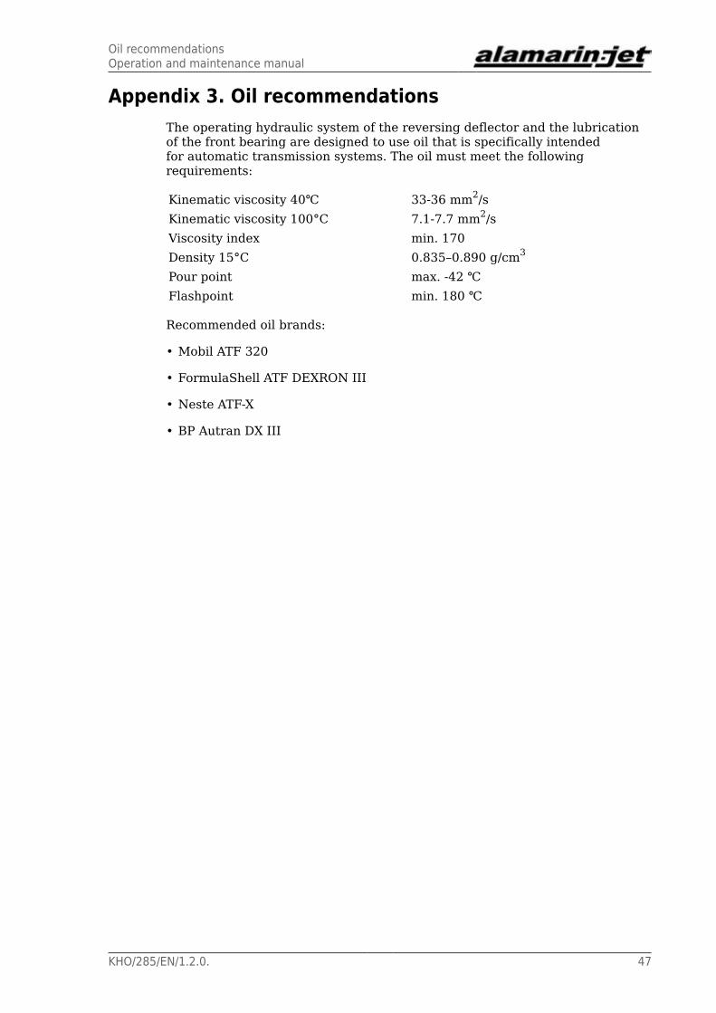
Appendix 3. Oil recommendationsThe operating hydraulic system of the reversing deflector and the lubricationof the front bearing are designed to use oil that is specifically intendedfor automatic transmission systems. The oil must meet the followingrequirements:
Kinematic viscosity 40℃ 33-36 mm2/sKinematic viscosity 100°C 7.1-7.7 mm2/sViscosity index min. 170Density 15°C 0.835–0.890 g/cm3
Pour point max. -42 ℃Flashpoint min. 180 ℃
Recommended oil brands:
• Mobil ATF 320
• FormulaShell ATF DEXRON III
• Neste ATF-X
• BP Autran DX III

Tightening torquesOperation and maintenance manual
48 KHO/285/EN/1.2.0.
Appendix 4. Tightening torquesUse the tightening torques from the table 4 when tightening the propulsionunit screws. The strength grade of an acid-proof A4-80 screw is equivalent to aclass 8.8 screw.
Table 4. Tightening torques of the screws
Strength grade 8.8 10.9 12.9Thread Tightening torque
(Nm) (*)
M5 5.5 (4) 8.1 (6) 9.5 (7)M6 9.6 (7) 14 (10) 16 (12)M8 23 (17) 34 (25) 40 (30)M10 46 (34) 67 (49) 79 (58)M12 79 (58) 115 (85) 135 (100)M16 145 (107) 215 (159) 250 (184)
(*) The tightening torque in pound-feet (approximate value) is marked in thetable in parentheses after the corresponding value in Nm.
A suitable thread locking compound that is good for all purposes is one ofmedium strength, for example. Loctite 242 or similar.

Test reportOperation and maintenance manual
KHO/285/EN/1.2.0. 49
Appendix 5. Test reportIt is recommended that a speed test report is filled out when the boat iscommissioned. The performance of the boat can later be compared to thisreport for the purpose of finding potential faults. The report template can befound on the following page.

Ala
mar
in-Je
t w
ill t
reat
all
info
rmat
ion
supp
lied
by y
ou a
s st
rict
ly c
onfid
entia
l.
Please return the completed form to Alamarin-Jet by post or e-mail. Post: Alamarin-Jet Oy, Tuomisentie 16, FI-62300 Härmä, Finland | E-mail: [email protected]/EN/1.0.0
Customer: Date:
Project/vessel:
ID:
Test report, Speed© Alamarin-Jet Oy
Test location:
Air temperature: °C Seastate:
Water temperature: °C Wind: m/s from
Jet type: Number of units:
Impeller type: Nozzle size:
Engine type:
Rated power: kW @ crankshaft [rpm]
Transmission type: Reduction ratio:
Load condition (total weight including all)
Test 1: kg LCG= m
Test 2: kg LCG= m
Test 1
RPM Speed 1 Speed 2 Average
1000
1200
1400
1600
1800
2000
2200
2400
2600
2800
3000
3200
3400
3600
3800
4000
4200
4400
4600
Test 2
RPM Speed 1 Speed 2 Average
1000
1200
1400
1600
1800
2000
2200
2400
2600
2800
3000
3200
3400
3600
3800
4000
4200
4400
4600
Instructions: Weight is to be calculated including all weight on board speed 1 and speed 2 are measured to opposite wind directions
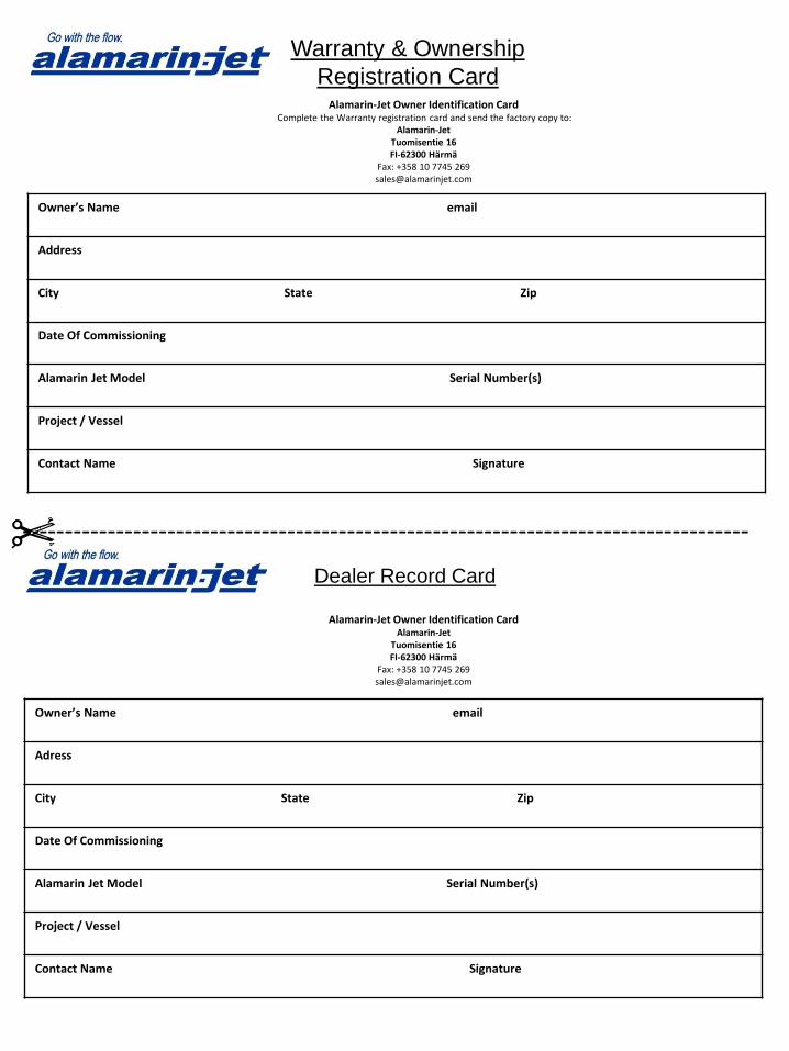
Warranty & Ownership
Registration CardAlamarin-Jet Owner Identification Card
Complete the Warranty registration card and send the factory copy to:Alamarin-Jet
Tuomisentie 16FI-62300 Härmä
Fax: +358 10 7745 [email protected]
Owner’s Name email
Address
City State Zip
Date Of Commissioning
Alamarin Jet Model Serial Number(s)
Project / Vessel
Contact Name Signature
Dealer Record Card
Owner’s Name email
Adress
City State Zip
Date Of Commissioning
Alamarin Jet Model Serial Number(s)
Project / Vessel
Contact Name Signature
-------------------------------------------------------------------------------------
Alamarin-Jet Owner Identification CardAlamarin-Jet
Tuomisentie 16FI-62300 Härmä
Fax: +358 10 7745 [email protected]