operation and maintenance manualautobaler.com.au/wp...ti100-ti200-operation-manual.pdf · operation...
TRANSCRIPT
AAUTOBALERUTOBALER
Operation Manual
TI100/tI200SERIES
Trethewey Industries14 Carl Baer Circuit
New England HighwayDeepwater NSW 2371
Australia

TiBMan016Rev02Feb14 2
Owners Manual
Thank you for choosing Autobaler TI100/TI200. It is our wish that you remain very happy with the performance and service given by your baler and our service backup staff.
For operating this baler properly, please take time to read this manual thoroughly before start to operate your baler.
Keep this manual handy for future reference.
The information contained in this manual is basic information. If you require information over and above what is supplied in this manual, please contact the Autobaler service hotline on 1800 888 403.
Models covered by this manual
TI100/TI200 Autobaler
NoteTraining is required to operate Autobalers.Training is required to service Autobalers.
Autobalers are protected by International Patents and Patent Applications.
TiBMan016Rev02Feb14 3

OPERATION AND MAINTENANCE MANUAL
USER MANUAL
SPECIFICATION MANUAL
MACHINE - AUTOBALER and CYBERSMART CONTROLLERMODEL - TI100/TI200
AUTOBALER SERIAL NUMBER - ________________CONTROLLER SERIAL NUMBER - ________________
Name and Address of Manufacturer
Trethewey Industries14 Carl Baer Circuit
Deepwater NSW 2371Australia
Please Read This Document BEFORE Operating the Machinery
TiBMan016Rev02Feb14 4

WARRANTYTo maintain warranty the baler must be serviced in accordance with the manufacturers recommendations outlined in chapter 9 and the service booklet.
The firm guarantees the machine herby described has been designed in compliance with all regulations in force, in particular safety and health regulations. The machine has undergone successful testing. (See test certificate enclosed.)
The warranty covers a period of 12 months. It does not cover electrical motors and tools. Extended warranty to 5 years is available
The purchaser is entitled to the replacement of faulty parts. Shipping and packing costs are at the purchaser’s expense.
The warranty does not cover damage caused by: Falls or careless handling of the machine, incorrect operation, and non-compliance with the maintenance rules. Any tampering with the machine, especially with its safety devices, automatically voids warranty. The manufacturer will be freed from any responsibility.
No claim for damages shall be accepted in cases where the machine has been laying idle for a long period of time.
The serial number on the machine is a main reference for the warranty, instructions manual and after sales service and identifies the machine in case of need.
Serial Number must be quoted in all correspondence.
NOTESThe machines are manufactured in compliance with the accident prevention rules in force.
The machines strictly comply with the instructions contained in the manual to obtain the best performance from the machines. Strict compliance with the rules contained will ensure optimum results and avoid any inconvenience caused by the non-compliance of operation and maintenance instructions.
To avoid contacting the manufacturer for problems which can be easily solved, closely follow the instructions given below.
If the help of our technical assistance service is still required after having strictly complied with the instructions given, the buyer must supply all the technical indications necessary to effectively determine the problem. This will enable our technical assistance service to intervene quickly and efficiently on the machine. Copies of the instructions manual may be requested upon indication of the machine serial number.
IMPORTANTUpon delivery of the machine, the consumer must make sure that all the devices indicated in the paragraph on the safety manual are present and working correctly. Furthermore, those devises which are not mounted at the time of delivery to facilitate transport must be mounted in conformity with the instructions indicated.
When ordering spare parts it is necessary to state: Machine Model Serial Number and Year of Manufacture Item Reference Number
Without the Serial Number, no spare parts will be delivered!
DEFINITIONSUser: The person, body or company who has bought or rented the machine and intends to employ the users trained and inducted in its safe use & operation.Operator: The physical person authorised by either the user or a representative of Trethewey Industries to operate the machine after having been suitably trained on the use and specific risks of the machine.Authorised Person: The physical skilled person authorised by the user to carry out maintenance or installation/initialisation on the machine.Dangerous Zone: Any dangerous zone as marked on the baler either entirely or partially.
PURPOSE OF MACHINEThis machine has been designed to be mainly used in recycling stations or similar applications. This machine has been designed for the compaction of cardboard, paper and similar fibourous materials. Use differing from the above is to be considered inappropriate and prohibited. The machine operator must be trained and informed of risks and must have the instruction manual at their disposal. The operator must not work with any guards or safety devices inoperative or missing. The baler must not be operated in any non-safety-compliant condition.
RISKSDuring the pressing phase, the operator must never put hands or use tools in the compaction area.
TiBMan016Rev02Feb14 5

CopyrightManual
INDEX
Warranty 5Scope 7Manufacturing Plate 7Declaration of Conformity 8Compliance 9Baler Test Report 10-14Hazard Identification 15Installation of Overhead Safety Canopy 16
Chapter 1Warnings 17Copy of Warning Notices 17
Chapter 2 - Lifting & Handling InstructionsSpecifications 18Transporting the Autobaler Safely 18Baler Relocation Procedure 18Removing the baler from the pallet 18Locating from truck to dock 18Work Method Statement 19
Chapter 3 – SafetyLocation of Autobaler 20Area of Operation 20Operation of Autobaler 20Safety Clothing / Footwear 20Safety Essentials 21
Chapter 4 – Operation of AutobalerBale removal procedure 22Twining up the TI100/TI200 23-25Controller layout and function 26-27
Chapter 5 – TrainingTrainer Material 28-43Trainee Particulars Kit 44-46
Chapter 6 – Maintenance & Cleaning SectionMaintenance Definition 47Weekly maintenance Check 47Preventative Maintenance 47Machine Cleaning 47General Housekeeping 47Service Intervals 47Recommended Lubricants 48Data Sheet - Pro-ma MBL8 Grease 48-49Material Safety Data Sheet – Super-hydraulic 50-51
Chapter 7 – Drawings 52-53
TiBMan016Rev02Feb14 6

SCOPEBackgroundAutobalers are a unique compacting machine featuring an open top system to facilitate loading of the baler with materials. Autobalers offer considerable time savings when compared with most other baler types. The time to compact is reduced on account of no doors to open and close each time materials are deposited. The Autobaler can be loaded during any part of its cycle path.
Autobalers are a safe machine reducing many of the common injuries associated with conventional balers such as strain injuries from pushing and forcing of materials into fixed sized areas. Many injuries also occur due to material breakdown with knives and other injury creating devices. AUTOBALER REQUIRES NO MATERIAL BREAKDOWN.
Autobalers are an extremely versatile machine being able to compact a large range of materials i.e.: paper, cardboard, plastics, rubber tyres, wool and most otherwise compactable materials. Autobalers come in a ten model capacity range from 80 to 500+ kg to best suit particular customer requirements. Autobalers are a quality machine offering unparalleled safety, amazing efficiency and huge labour savings.
Trethewey Industries have vast experience in the manufacture of quality baling machines, having produced in excess of 500 agricultural baling machines. Five years ago Trethewey’s developed the Autobaler for commercial use, in particular to be used in Supermarkets and Recyclers. Trethewey Industries are situated on the New England Hwy at Deepwater NSW. Trethewey Industries location is ideal for servicing our national markets. Trethewey Industries focus is to develop machines which totally satisfy customer requirements in performance, quality, service, economy and safety.
Autobalers were developed to give the maximum efficiency and safety possible. Autobalers are designed for loose materials and are not recommended for solid materials (i.e. hard wooden or metallic objects) as these may cause machine damage. The manufacturers are happy to assess your needs and make recommendations and give assurances on the type of baler which will best suit your requirements.
Autobalers are built to comply with the highest national and international standards.
Autobalers are protected by International Patents and Patent Applications.
Manufacturing Plate:
TiBMan016Rev02Feb14 7

DECLARATION OF CONFORMITY98/37/EC Machinery Directive
73/23/EEC Low Voltage Directive89/336/EEC EMC Directive
Name of manufacturer or supplierTrethewey Industries Pty Ltd
Full postal address including country of origin14 Carl Baer Circuit, Deepwater, NSW 2371, Australia
Description of productPaper & Cardboard Baling Machine
Name, type or model, batch or serial numberType - AutobalerMake - Trethewey Industries Pty LtdModel – TI100/TI200Location – 14 Carl Baer Circuit, Deepwater, NSW 2371 AustraliaSupply - 415V ac 3 -Serial No: _____________________Mass Weight - __________________
Standards used, including number, title, issue date and other relative documentsSee attached sheets
Place of issue Address of Authorised representative in Europe
Name of authorised representative:______________________________________
Position of authorised representative:____________________________________
Full postal address if different from manufacturersAddress of Authorised Representative in Europe
Declaration
I declare that as the authorised representative, the above information in relation to the supply / manufacture of this product is in conformity with the stated standards and other related documents following the provisions of the above Directives and their amendments.
Signature of authorised representative _____________________Date_________
TiBMan016Rev02Feb14 8

Trethewey Industries
Autobaler
TiBMan016Rev02Feb14 9

Trethewey Industries Pty Ltd14 Carl Baer Circuit
DeepwaterNSW. 2371
14 November 2003
ASSESSMENT REPORTAUTOBALER
FOR COMPLIANCE WITH MACHINERYDIRECTIVE 98/37/EC
THIS REPORT IS PREPARED BY RISKPLANT CONSULTANTS PTY LTD FOR RISK MANAGEMENT PURPOSES, AND ITS CONTENTS ARE PROVIDED EXPRESSLY FOR THE
NAMED CLIENT FOR ITS OWN USE
NO RESPONSIBILITY IS ACCEPTED FOR THE USE OF, OR RELIANCE UPON THIS REPORT, IN WHOLE OR IN PART, BY ANY THIRD PARTY.
Prepared byRoger Lim, MIE Aust, CPEng, MSIA
RiskPlant Consultants Pty Ltd(ABN 78 086 256 206)
PO Box 115BLACKBURN NORTH VIC 3130
Ph: (03) 9877 4519Fax: (03) 9877 4569
NATA Accredited (No. 14155)Machinery Safety
Inspection Services
TiBMan016Rev02Feb14 10

Baler Test Report
Comprehensive Autobaler Test Report
Date:
Serial No:
Testing Officer:
Electrical Test Performed By:
Noise Emission Test:
Hydraulic Test:
Autobaler Quality and Reliability Test - Full Mechanical Test
Test Report No:
Testing Officer:
Operational Test Report No:
Testing Officer:
Lubrication Test Report No:
Testing Officer:
Testing Officer:
Signature:
TiBMan016Rev02Feb14 11
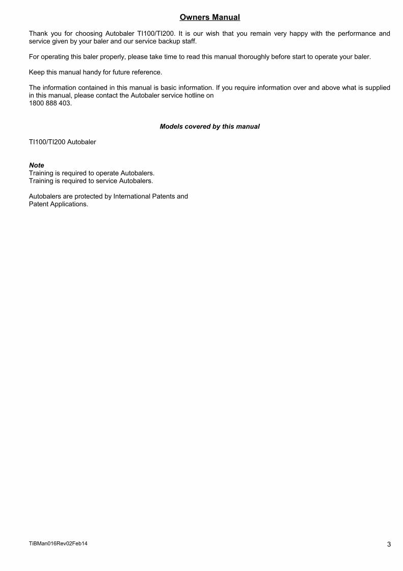
Hydraulic Pressure and Performance Test
“Report on Safety and Hydraulic Performance”
This report is suitable for pressure systems below 2500 psi.
System Pressure Required:
System Pressure on Test:
System Pressure Spikes:
Pressure Switch Firing Range:
Pressure Switch Firing Test:
Hydraulic Delivery Hose Rating:
Fluid Type and Grade:
Cylinder Brand and Type:
Duration of Cycle Test:
Date:
Inspector:
Signature:
TiBMan016Rev02Feb14 12
Hydraulic 32 Grade

Noise Emission Test Report
Baler Noise Emission report - the test done from five positions:-
a. From each side at a distance of 1m from the machine
b. At a distance of 1m above the machine
Decibel monitor type and number:
Test one metre from front:
Test one metre from left side:
Test one metre from right side:
Test one metre from back:
Test one metre above machine:
Injury precautions required:
Date of Inspection:
Inspection No:
Inspector:
Signed:
TiBMan016Rev02Feb14 13
Tenma 72.6604
70 Db
70 Db
70 Db
Ear Protection Must be worn if noise exceed 85 DB
70 Db
70 Db

Earth Bonding and Electrical Test
Report on Safety Inspection and Testing of Electrical Equipment
This report is suitable for class 1 protectively earthed 3 phase 415V equipment. The test has been carried out in accordance with AS/NZS 3760, with the following electrical and visual inspections:
500V Insulation Resistance Tests Active 1 to earth: Pass Fail
Active 2 to earth: Pass Fail Active 3 to earth: Pass Fail
Earthing continuity: Pass Fail
Flexible supply cord:- External visual inspection of plug connection: Pass Fail Visual inspection of cord termination to equipment: Pass Fail
Visual inspection of wire terminationin electric motor terminal housing: Pass Fail
Date:
Inspection number:
Inspector:
Inspector registration number:
Signed:…………………………………………………………………………
TiBMan016Rev02Feb14 14

Trethewey IndustriesNew Machinery Hazard Identification assessment and Control
Description: Autobaler Model: TI100/TI200 Brand:
Developed in Co-operation Between AWISA and Australia Chamber of Manufactures.This program is based upon the Australian Worksafe Standard for Plant NOHSC:1010-1994
Item No. Hazard Identification Hazard Assessment Risk control Strategies
A Entanglement Very Low Do not reach into baler. Operator Training
C Cutting, stabbing, puncturing Very Low Use only safety knife for bale tie off.
D Shearing Nil
E High Temperature Nil
F Striking Moderate Upper or lower door rebound. Operator Training
G Crushing Low Bale ejection. Operator Training
H Electrical Low Operator Training
O Other hazards, noise dust. Moderate noise Noise if operated with insufficient materials in hopper. Operator training
TiBMan016Rev02Feb14 15
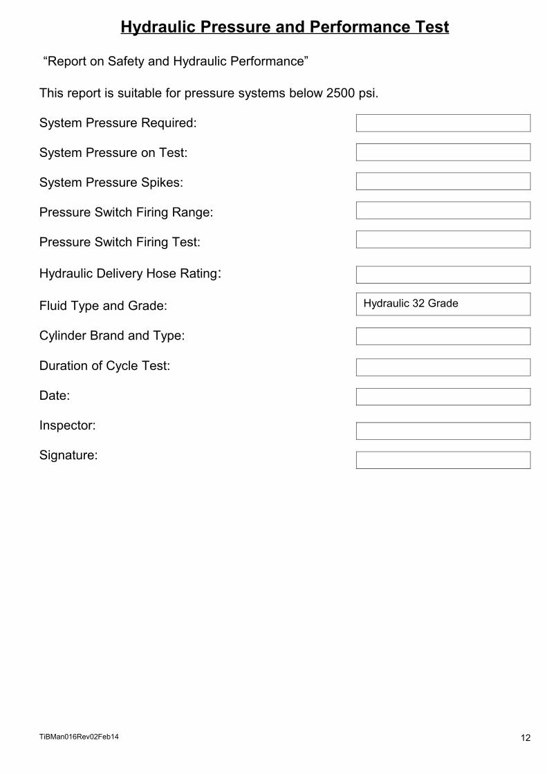
Installation Instructions for the Overhead Safety Canopy
FITTING OF THE OVERHEAD FRAME From within the baler lift frame – the rear support legs will telescope out When the holes I the telescoping rear legs appear, slide in retaining bolts to hold the frame in position. This
operation may require two people or the use of a fork lift or mechanical lifting device. Firm up the grub screws on these legs Fit the mesh sections supplied – these will only fit one way. Tighten up the grub screws in the saddles to secure the mesh tabs to the baler The mesh frames should be now securely attached to the baler frame Firm up grub screws on baler saddles locking overhead frame into position. Note: mesh hopper must be on the
inside of the legs (see illustration 2) Frame should now be as the picture below,
If you require further information on the fitting procedure, please contact the manufacturers on:- 1800 888 403 or 02 67 345403
FITTING OF THE SAFETY CANOPY:
Fitted Overhead Safety Canopy.
Rear Canopy legs position
Mesh mounting lugs
TiBMan016Rev02Feb14 16

CHAPTER 1 Warnings
1. Autobalers must only be operated by qualified people.2. Only qualified people to service or repair Autobalers.3. Before servicing or repair familiarise yourself with the relevant instruction manual.4. The Autobaler must not be used in a manner contrary to the manufacturer’s instructions.5. Prior to moving the Autobaler ensure the fork lift capacity is at least 1.5 tonne.6. On installation or repair ensure the machine is effectively earthed. (All electrical work to be carried out by
qualified electrician).7. Always disconnect the electrical supply before servicing or repair due to electrical hazard.
Failure to observe Safety Precautions could lead to severe injury.
We recommend operators using the following personal protective equipment:-1. Safety glasses2. Safety shoes3. Safety gloves
COPY OF WARNING NOTICES ON MACHINE(INCLUDING NAMEPLATE)
TiBMan016Rev02Feb14 17

CHAPTER 2 LIFTING AND HANDLING INSTRUCTIONS OF THE AUTOBALER
TI100 SpecificationsBale Weights 100-140kgsBale Size 750 x 750 x 1000Cycle Time 23 secondsUnit Weight 1250kgThrust Load 5350kgPower 3Kw 3 phasePlug required 4pin Clipsal compatibleHeight 2500mmWidth 1940mmDepth 920mmTransport Height 2050mmBaler Capacity 2-3 bales per hour
TI200 SpecificationsBale Weights 175-200kgsBale Size 750 x 750 x 1000 (mm)Cycle Time 23 secondsUnit Weight 1650kgThrust Load 10160kgPower 3Kw 3 phase 20ampPlug Required 4pin Clipsal compatibleHeight 2500mm Width 1940mmDepth 920mmTransport height 2050mmBaler Capacity 2-3 bales per hour
TRANSPORTING THE AUTOBALER SAFELYWhen moving or relocating the baler always follow the Work Method Statement, in most cases it will be a requirement of the organization that the Work Method Statement be completed signed and handed in to the appropriate person or persons for approval before carrying out the task. The following procedure is for the safe transportation and movement of the Autobaler
1. BALER RELOCATION PROCEDURE1. Before removing or lifting the baler ensure that the lifting equipment is in good
order and has capacity to lift the baler – check baler weight in baler specifications.
2. Autobalers balers can be moved with a forklift unit or a pallet truck3. Before moving the baler ensure that there is sufficient clearance (height wise) 4. Where possible attach the baler to the moving means to prevent possible
overbalance5. Where required situate traffic cones and safety barriers6. Always transport baler units as close to the ground level as possible – if
forward movement is required always used another qualified person as a guide
7. Proceed slowly – downhill grade always in reverse
2. REMOVING THE AUTOBALER FROM THE PALLETa. Unwrap and cut metal strappingb. Insert the fork lift tines beneath the front lower door. Ensure that the fork lift tines are fully through to the rear baler
wall.c. Lift the baler no more than 80mm off the pallet & check again to ensure sufficient tine protrusion through the rear slotsd. With tines under the baler always move:-
as close as possible to the floor at idle speed only in reverse to ensure good vision
Note: When transporting the Autobaler where lifting on a truck is requireda. Never lift the baler more than 300mm unless on a pallet or strapped securely to the fork lift, as the baler could slip off
the tines (metal to metal)b. If lifting the baler from beneath the baler base, fasten the baler to the fork mask using strap or chainc. When lifting the baler more than 300mm, always be on level ground and never transport the baler in an elevated
positiond. When transporting or moving the baler on the fork lift, always travel in reverse to ensure good visione. Safety Equipment: Compliant safety boots, high visibility vest, hearing protection, eye protection. Head
protection if required. 3.LOCATING FROM TRUCK TO DOCK.When loading the baler for its final destination, the baler is to be loaded in such a way as to facilitate removal at the customer end.ie. If the baler is to be unloaded using a forklift truck, baler should be situated accordingly.NB: if baler is to be unloaded via pallet jack, then the pallet containing the baler needs to be rotated through 90 degrees.
TiBMan016Rev02Feb14 18

Work Method Statement
Activity Contractor
Person completing this statement
Telephone
Date Contract Number
Key Steps Equipment or plant required Possible HazardsSafety controls including personal protective equipment (PPE)
Licenses, qualifications or work permits
1.
2.
3.
4.
5.
6.
7.
8.
9.

CHAPTER 3 SAFETY
A. Location of Autobaler: a. Never place the Autobaler near any landings or elevated loading docks, unless these areas have the
appropriate safety arrangements and approvals.b. Never place the Autobaler under a man hole, air conditioner, refrigeration unit, light or any position where a
service technician may have occasion to work above the machine.c. Never place the Autobaler on a loading dock, close to the edge or the above landings edge.d. Never place the Autobaler in a position where unauthorised persons have access.e. Always consult an OH&S officer.
B. Area of Operation:a. Ensure that baler trolley is stored in a position away from the operator’s passageway.b. Ensure that twine rolls & twine safety cage are positioned close to the right hand side of the Autobaler to
prevent tripping. If cage is provided with hooks, use these to affix cage to safety barrier.c. Ensure that electric lead is not in a hazardous position and is not left lying on the floor, particularly if there is a
chance of water being on the floor.
C. Operation of Autobaler:a. Always keep hands and arms out of the Autobaler hopper during operation.b. Always, when entering the pressing chamber for re-stringing etc, wait until the motor stops and turn the key to
the “Off” position.c. Never attempt to load heavy objects over the top door during the baling process, (reduce boxes of books,
brochures etc to smaller quantities).d. When removing full bales from the Autobaler, always use the Auto-eject or eject trolleye. When ejecting full bales, never pull on the twine in such a manner that if the twine breaks, or the knot fails, a
fall will result which may cause an injury.f. Always use the baler trolley, pallet jack or fork lift to relocate full bales.g. Always be aware of door rebound when opening top or bottom doors, always stand to the side.h. Never stand in front of the pressing chamber when ejecting full bales, always stand to the side, eject models
only.i. Never attempt to operate Autobaler with the front door open.j. Never attempt to clean, lubricate or work in the vicinity of the cylinders during operation.
SAFETY CLOTHING / FOOTWEARa. During assembly, location and operation of the baler, safety compliant footwear must be worn.b. Firm fitting work place compliant clothing must be worn.c. Safety compliant work place gloves, hearing protection and eye protection must be worn.d. General
Always remove Autobaler key when machine is not in operation, or is unattended.

SAFETY ESSENTIALS
1. Before commencing the baling process ensure that the bottom door is latched correctly to prevent the door bursting open during process.
2. Never climb onto the baler from any side or reach in during operation or stand on elevated objects.
3. When removing the bale, grip the handle of the eject trolley firmly and pull back with care.
4. Always place the bale transport trolley centrally and in the floor channels to prevent bale side roll.
5. On inclines, take care to prevent run away and potential injury to others.
6. Use only the safety knife for twine cutting.
7. To prevent strain injury ensure that the doors and latches open freely – lubrication may be required
8. Remove baler key if in a safety sensitive zone.
9. Never operate a faulty machine tag out and call 1800 888 403
10. Autobaler operators must be licences to legally operate Autobalers
11. Note smaller framed people or people of low strength and fitness can sustain injuries from over exertion with bale removal and location – ensure tat the operator is of sufficient strength and fitness to safely perform this task.

CHAPTER 4 OPERATION OF AUTOBALER
BALE REMOVAL PROCEDURELarger Autobaler are equipped with auto ejection systems the small 100 series have manual bale removal system
Removal of the BaleStep 1.Before commencing the baling especially with smaller granulated materials place a sheet of cardboard on the bottom of the baler to prevent clogging of the baler floor grooves.Step 2.Fully open both upper and lower baler doors using the bale extraction trolley supplied with the machine. Insert the trolley tines into the baler lots.
Step 3.With the trolley forks fully inserted, grip the top of the trolley handle firmly and pull back, carefully drawing the bale from the chamber. (note for ease for extraction the bottom door of the baler must be fully opened.)Step 4.With the bale extracted from the baler the bale can be wheeled away and stored.
SafetyThose responsible for the safe operation of the baler must:
1. Ensure that the persons removing the bale have been sufficiently trained in the safest removal procedure.2. Must be of sufficient strength and fitness to safely carry out this task.3. Bale trolley storage to prevent a tripping hazard – store the bale trolley with the forks beneath the left hand side
and the trolley against the baler.

TWINING UP THE TI100/TI200
The following procedure is for the twining of the TI100/TI200 Autobaler.Step 1.Place the roll of twine under the left hand side of the baler. The roll must be the correct side up. The draw end of the twine feeds from the entire of the roll from the top side. Twine type must comply with OH&S requirements (recommended twine type is Superlash8)
Step 2.From the drawn end lay the twine back approximately 200mm as shown
Step 3.Tie a knot in the end to form a non-slip loop as per illustration.
Step 4.In some instances a double know may be required as shown. The reason for this will be explained in a later step.

Step 5.Hook the looped twine end on the baler tab as per illustration 5 and take the twine to the opposite side as per illustration 6 then bring the twine back to left hand side as illustrated and cut off at this pint using the safety knife supplied illustration 7. This will give the correct length of twine required – Repeat this process three times to give the required amount to twine up the machine.
Illustration 5 Illustration 6
Illustration 7Step 6.Fully open all doors and step into the baler chamber (note before entering the baler turn the baler key to the off position) Hook the twine loop over the domed hook as illustrated on the left hand side.
Step 7.Take the twine down under the tab on the left side on the bottom then across and under the tab on the right hand side then up to the domed hook on the right hand side.
Step 8.

To attach the twine end to the domed hook on the right hand side rotate the twine end around the domed hook twice then tie off using one tie off loom only. Repeat this procedure on both side twines.
Step 9.Transverse twine (from rear to top)
1. Hook twine loop onto the domed hook on the rear inside wall of the baler.2. Place the twine under the tabs on the floor (near to front as illustrated).3. Holding the twine end in the left hand close the bottom door using the right hand.4. Twine will then come up the inside of the lower door over the top and attach to twine tab as in step 10.
Step 10.Twine end will come over the top of the bottom door and attach to twine tab by rotating the twine around the twine tab twice then inserting twine into tab slot as illustrated.

CONTROLLER LAYOUT AND FUNCTION
ControllerAlmost the total function of your Autobaler is via the Cybasmart control unit. The various functions of the controller are as follows:1. Isolating Switch - The isolating switch is situated on the upper end of the controller. The purpose of the isolating switch is to isolate the power to the unit when ever a service or repair is carried out. It is therefore the manufacturers’ recommendation that when ever the machine is tagged “out of service” that the tag be attached to the isolating switch via a padlock this will ensure that the machine will remain inactive and safe for the technician.
2. Power In - Power to the controller unit enters through the 3 phase power cable at the power in point. It is essential that the lead and plug be kept in good working order and free from possible damage and moisture entry. Note: all repairs to the electrical components must be carried out by those qualified to work with 3 phase power. If power at anytime becomes absent at the controller, (power light out), check the power entry system from the controller back to the main power source.
3. Serial Number - Every controller unit has its individual serial number. When ordering parts for the controller or the electrical system always quote the controller serial number as well as the baler serial number and date of manufacture.
4. Ignition Switch - The controller ignition switch has a security type key. If the baler is not in use or is in a public area it is advisable for the key to be removed. If additional keys are required these will need to be specially ordered from Farnells; from the baler manufacturer or the manufacturer’s agent or representative.
5. Emergency Stop Button - The emergency stop button is fro emergency use. The emergency stop disables all electrical functions within the baler systems. To activate the emergency stop simply push the button firmly in. To release the emergency stop button to the active mode rotate the button clockwise until the button pops forward.
6. Magnetic Door Switch - The magnetic door switch is activated at the top of the upper door adjacent to the controller unit. One half of the magnetic switch is attached to the controller via plug socket (7) the other section of the switch is attached to the door. It is essential that these sections of the switch be correctly adjusted to each other. The two halves of the switch must never come into contact with each other or serious switch damage may occur. A correctly adjusted switch will have each section squarely situated to each other and will have a minimum of 1.5mm clearance to each other with a maximum clearance at any time of 4mm. More clearance than this will create a door open light to illuminate on the controller. During operation the movement in the top door may create a switch movement either apart of out of line with each other – this will depend on the machine and active the door open light. If switch adjustment is required adjust then carefully close the door ensuring that the two sections of the magnetic switch have the required clearance to prevent switch damage.
Warning (20) Full Bale Light (13) Bale Counter (8)Serial Number (3) Isolating Switch (1) Retract (11) Eject (9)
Up IndicatorDown IndicatorPower IndicatorActive IndicatorPower to motor port (14)Polarity Change Port (15)Thermo Plug Accessories (16)Solenoids full bale pressure switch (18) (19)
PowerIn (2)
Ignition Key (4)
Emergency Stop (5)
Magnetic Switch
(6)
Power Boost
(12)
Cycle (10)
Fuse (21)

7. Door Magnetic Switch Plug - This is the plug as described in (6) that is attached to the controller from the second half of the Magnetic Door Switch
8. Bale Counter - The bale counter as the came suggests simply counts the number of bales being compacted. The bale counter performs an important function. Service intervals are time base or in situation of above average use are based on the number of bales completed. Refer to the Service Section of you Operators Manual for service intervals.
9. Eject - The eject button activates the eject system removing the completed bale from the baler chamber. To operate the eject the bale must be complete with twines or fasteners secured, pressing fingers fully retracted, both doors fully open, and the bale transport trolley situated correctly in front of the bale to be ejected. The operator must stand to the side and safe from the passage of the ejecting bale. When ejecting the bale the eject button must be kept activated until the bale is fully ejected into the trolley.
10. Cycle Button - The cycle button activates the cycle mode, when activated the baler arms will come down if in the retracted position. If the baler arms are down the baler will do a full cycle, i.e. arms up then back down. This should result in the system being “activated” the system active light will be illuminated. When materials are deposited into the baler chamber and the infra red beam emitting from the controller to the receiver on the rear wall is broken the baler will automatically start and do a full cycle, while ever the infrared beam remains broken the baler will continue to cycle until the beam is cleared of material.
11. Retract Button - The purpose of the retract button is to raise the pressing arms to a vertical (out of the chamber position) and to remain there. This function is used when the bale is complete, tied off and ready to be ejected.
12. Power Boost Button - The power boost button provision is used only after the full bale light and indicator has signalled a full bale. This button applies extra power to fully close the four main power hydraulic cylinders to give a constant bale size and length.
13. Full Bale Light and Siren - When a full bale has been achieved the full bale light and siren will signal full bale. When these come on the automatic function feature of the baler will cease. The baler though can be manually operated to draw down surplus materials. A large piece of material can also at this point be placed in the chamber, the baler manually cycled to form a flat tidy top bale.
14. Power to Motor Port - The power to motor port couples the motor and the controller together. The power socket can be removed by rotating the power to motor socket nut.
15. Polarity Change Port - This port can be interchanged with the Power to Motor Port (14) to reverse the polarity of the motor. (Note motor must always rotate in a clockwise direction).
16. Thermo and Accessories Plug (pug cap on spare port must always be attached!) - This port has the wiring to the thermo unit which detects overheated hydraulic oil and closes down the machine when the oil exceeds 60 degrees celsius. This will show on the door open light and also on the controller display as a overheat warning.
17. Warnings - The bale counter display also doubles as a display screen showing various problem indicators i.e. pressure switch, overheating etc.
18. Connection Socket - The connection socket contains the wiring looms from the controller to the following functions:1. Solenoid valve to main compaction arms2. Solenoid valve to bale eject cylinder3. Pressure switch control wires4. Power boost wiring5. Full Bale switch
19. Light Indicator Grouping - A series of vertical lights show the various functions of the baler: The up indicator light (top light) illuminates when the cycle button is activated and baler arms are rising. The down light will illuminate when the baler direction is down. The third light down (red is the power light. This light should illuminate when the key switch is turned on 2. The eject
button is released and indicates power at the baler. Door open light will indicate when the top door is open or the machine has developed a system fault such as an
overheated system or pressure related problem. The active light indicated that the baler system is active and will automatically start and cycle when materials break
the infrared beam.
20. Warning - Warning symbol indicates the presence of dangerous voltage within and is a warning to those qualified to ensure a power supply is disconnected before opening of the unit. To those who are not qualified to work with high voltage a warning not to open the unit with authorisation.
21. Fuse - The controllers’ electronic system is protected by a fuse. To access the fuse unscrew the fuse holder.Fuse Type: 32mm glass fast blow fuse
Fuse Value: 4A

AUTOBALER
TRAINERMATERIAL
Key
Emergency Stop
Control Panel
Upper Door Handle
Lower Door Handle
Full Bale Light
Bale Counter Safety Bar

AUTOBALER TRAINER MATERIAL
INDEX1. Controller Operation
2. Set Up3. Baler Fit Out4. Initial Set5. Tying the Loop6. Transverse Twining7. Initial Fill8. Baler Operation9. Tidy Bale Procedure10. Tying Off11. Transverse Twine tie off12. Retracting Fingers13. Opening the Doors14. Bale Removal and
-Storage Safety Procedure
Baler Serial No: ___________________________________________
Date: _______________________________________________

Customer: _______________________________________________
Address: _______________________________________________
_______________________________________________
_______________________________________________
_______________________________________________
Trainer: _______________________________________________
Signature: _______________________________________________

1. Controller Operation
1. Turn the key on – power light on
2. Engage coded key bar – door open light on.3. Disengage emergency stop key rotation4. Cycle button to cycle5. Retract button to raise fingers only6. Red light and beeper full bale indicators
Trainer Signature of compliance:
___________________________________________________________

2. Set Up
1. Remove the protective wrapping2. Move all sundry items from within the baler3. When moving or relocating the baler carefully follow the lifting instruction and safety procedure.
Trainer Signature of compliance:
___________________________________________________________
3
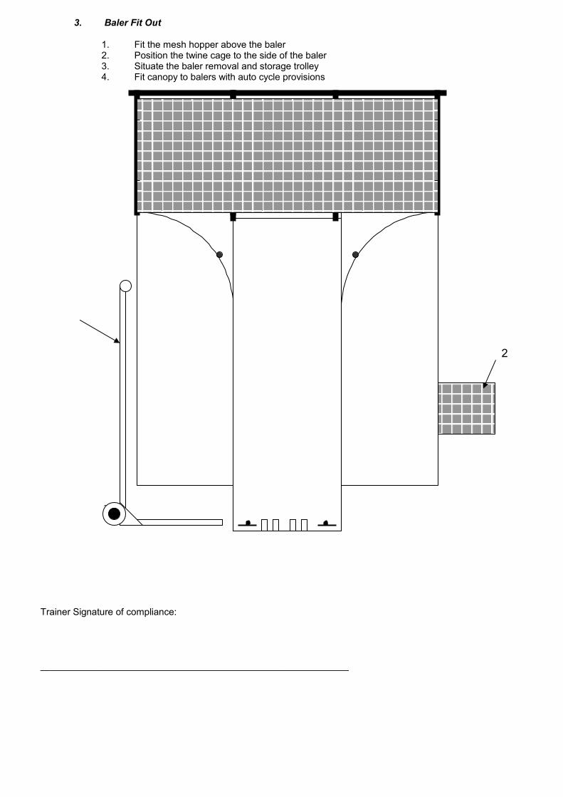
3. Baler Fit Out
1. Fit the mesh hopper above the baler2. Position the twine cage to the side of the baler3. Situate the baler removal and storage trolley4. Fit canopy to balers with auto cycle provisions
Trainer Signature of compliance:
___________________________________________________________
2

4. Initial Set
1. Turn the controller key on2. Press retract button – check motor rotation for clockwise direction – stand fingers up and clear of the
bale chamber3. Check that twine roll is correct side up – draw twine and cut to length as on the illustration below (all
three twines are the same length)
Trainer Signature of compliance:
___________________________________________________________

5. Tying the Loop
1. Tie the double loop in twine ends.2. Open all doors3. Attach the outer loops of the twine to the left hand side of the baler4. Down to tab on left side then across the floor then under the tab on the right hand side.5. Rotate the twine end around the eye bolt twice then tie off with one loop6. Repeat his process on all three twines
Trainer Signature of compliance:
___________________________________________________________
50-75mm 50-75mm
A D
B C

6. Transverse Twining
1. Hook twine loop or domed hook on rear will of baler2. Position twine under rear twine tab on the baler floor3. Position twine under front floor tab4. Close bottom door and brine twine up the inside of the front door and over the top and fix twine end to
twine tab by rotating once then fixing the twine in the tab slot.
Trainer Signature of compliance:
___________________________________________________________
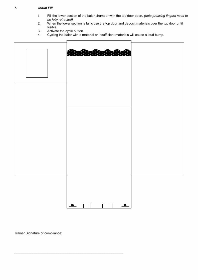
7. Initial Fill
1. Fill the lower section of the baler chamber with the top door open. (note pressing fingers need to be fully retracted)
2. When the lower section is full close the top door and deposit materials over the top door until visible.
3. Activate the cycle button4. Cycling the baler with o material or insufficient materials will cause a loud bump.
Trainer Signature of compliance:
___________________________________________________________

8. Baler Operation
1. TI100 & TI200 balers have automatic function.2. Button or automatic activation is required for each cycle.3. Peddle (or foot activation is optional) on TI100 & TI200 units
Trainer Signature of compliance:
___________________________________________________________
2
3

9. Tidy Bale Procedure
1. Last 10% of the bale, flattened material laid flat2. When full bale light comes on:
i. Remove excess material by cycling manually by pressing the cycle button (several cycles may be required)
ii. For neat top, place large flattened material on the top of the bale and activate cycle button.
Trainer Signature of compliance:
___________________________________________________________
2
4
1

10. Tying Off
1. Open the top door2. Remove loose or protruding materials from above the fingers3. Unhook the twines on the looped ends (cut upper loop if too tight and use lower loop to tie off)4. Untie plain twine end and insert through the loop. Pull tight and tie off securely.
Trainer Signature of compliance:
___________________________________________________________
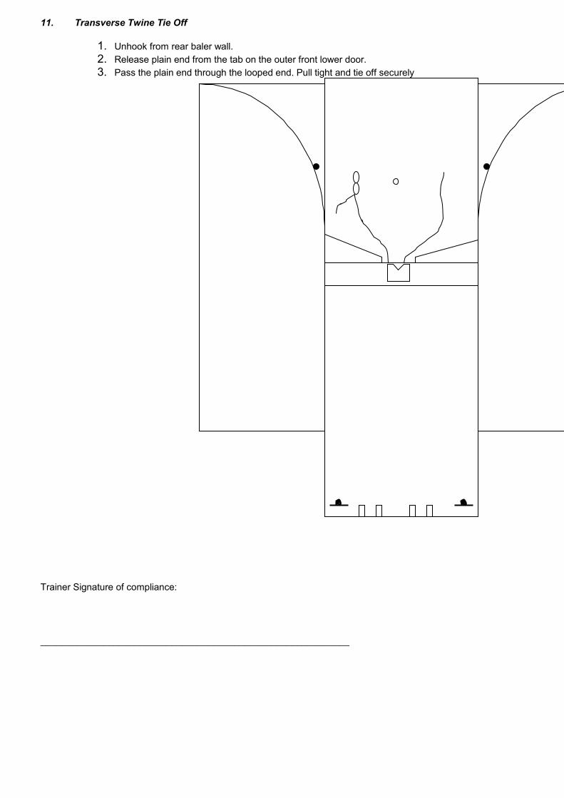
11. Transverse Twine Tie Off
1. Unhook from rear baler wall.2. Release plain end from the tab on the outer front lower door.3. Pass the plain end through the looped end. Pull tight and tie off securely
Trainer Signature of compliance:
___________________________________________________________

12. Retracting Fingers
1. Close top door2. Turn power on3. Press retract button (hold button until the fingers are fully retracted)
Trainer Signature of compliance:
___________________________________________________________

13. Opening the doors
1. Open the top door (beware of possible rebound)2. Open the bottom door (beware of possible rebound)3. Open the bottom door fully4. Insert the bale removal trolley tines into slots in the baler floor or with auto eject models position the
bale transport trolley for ejection onto the trolley.5. When fully inserted gently pull back on trolley handle and wheel away for storage.6. Note do not open the bottom door with the fingers down.
Trainer Signature of compliance:
___________________________________________________________
4

14. Bale removal and storage safety procedure
1. Ensure that the person removing the bale is of sufficient strength and fitness to prevent personal injury.2. Heavier bales may require a three wheeled trolley, supplied as an option at the customers request.3. Beware of over balance and possible back or foot injury.
Trainer Signature of compliance:
___________________________________________________________

Autobaler Trainee Particulars (Kit)
Company: __________________________________________________________________________________
Address: __________________________________________________________________________________
__________________________________________________________________________________
__________________________________________________________________________________
Trainee Name: __________________________________________________________________________________(Print Clearly in Capitals)
Address: __________________________________________________________________________________
__________________________________________________________________________________
__________________________________________________________________________________
Phone No: __________________________________________________________________________________
Employer: __________________________________________________________________________________
Date Of Training: ____________________________________________________________________________
Autobaler Model Trained To Use: ____________________________________________________________________
I, ________________________________________________________________ (Trainer) witnessed the competency of
_____________________________________________________ In the safe competent use of the Autobaler Model
__________________________________________________and I received a copy of the Training Manual.
I hereby validate this assessment.
Signed (Trainer): ____________________________________________________________________________
Date ____________________________________________________________________________
Signed (Trainee) ____________________________________________________________________________
Date ____________________________________________________________________________
Special Comments ____________________________________________________________________________
_______________________________________________________________________________________________
_______________________________________________________________________________________________
_______________________________________________________________________________________________
_______________________________________________________________________________________________
_______________________________________________________________________________________________
_______________________________________________________________________________________________

Trainee Exam Questions (Autobaler TI100/TI200 Series)
1. If the baler is in a public access area and the baler will be unattended for a long period, what precaution for public safety should you take:
a. Sit and watch the baler………………………………………..b. Remove the key………………………………………………..c. Do nothing………………………………………….……………
2. What function does the retract button have:a. General operation………………………………………………b. Cycles the baler…………………………………………………c. Raises the fingers only…………………………………………
3. The purpose of the safety bar is:a. To do chin ups…………………………………………………..b. For emergency stopping………………………………………..c. No particular use………………………………………………...
4. When twining the baler at what position should the baler fingers be:a. Right down………………………………………………………..b. Half way down…………………………………………………….c. Fully up…………………………………………………………….
5. What is the purpose of the plastic tabs on the base (floor) of the baler:a. Decoration…………………………………………………………b. Place twine beneath……………………………………………...c. Structural…………………………………………………………..
6. The last 10 - 20% of the bale, how would you place flattened material:a. On its edge………………………………………………………...b. Anyway…………………………………………………………….c. Flat in the baler……………………………………………………
7. Tying of the finished bale should be done with the:a. Fingers up (retracted)……………………………………………..b. Fingers half way……………………………………………………c. Fingers right down…………………………………………………
8. Opening of the top door, I should:a. Open it the best I can……………………………………………..b. It doesn’t matter……………………………………………………c. Grip the handle firmly……………………………………………..

10. Ejecting the bale, I should:a. Pull as hard as I can on the twine…..…………………………..b. Place the eject trolley in front of the baler with all doors open and
in a roll away from the baler position…………….……………….…c. the best I can…………………………..…………………………..
11. Where should the bale transport trolley be stored when not in use:a. Under the right hand side…………………………………………b. Under the left hand side…………………………………………..c. Anywhere…………………………………………………………...
12. Real heavy objects i.e. boxes of magazines etc. How should I load them into the baler:
a. Over the top door…………………………………………………b. Open the top door………………………………………………..c. The best I can…………………………………………………….
13. If the baler operates with the top door open, I must:a. Continue as normal………………………………………………..b. Shut the machine off, remove the key and place out of order sign…………………………………………………………………..…c. Take care……………………………………………………………
14. Was the knot test passed? Yes No
CHAPTER 6MAINTENANCE & CLEANING SECTION
Always disconnect Electrical Supply before Changing Any Equipment!A. MAINTENANCE DEFINITION
Standard Maintenance:- A service provided at four monthly.Average usage:- A baler producing up to 5 bales per day - recommended preventative maintenance period not to exceed four months and to be serviced according to the standard servicing schedule.High usage:- a baler producing more than five bales per day - recommended service period not to exceed four months and to be serviced according to the standard servicing schedule.Major Maintenance:- A serviced preformed every 12 months or every 660 bales and to be serviced according to the standard servicing schedule. A major service has the additional service elements.
1. Oil filter change2. Hydraulic oil test and changed if required3. Finger lock spring change4. Main cylinder pivot pin check for wear or fatigue
B. WEEKLY MAINTENANCE CHECKa. Check safety guards around moving parts. Are they in place? Are they damaged?b. Check Autobaler key switch, is it functional and in good order?c. Check emergency stop button, is it functional and in good order?d. Check safety bar, is it functional and in good order?e. Check power lead, is it undamaged? Is it clear of any moisture?f. Check Autobaler response to opening top door. Opening more then 50mm (approx 2 inches) should cause the
machine to cease cycling.
If any of the above checks reveal damage or malfunction, the machine should be shut down and the key removed until the fault is repaired
C. PREVENTATIVE MAINTENANCE:a. Every 4 months, or every 500 bales, the operation of the Autobaler should be checked by a qualified person to ensure
that all safety features are functioning correctly and are undamaged.b. From time to time, a qualified electrician should inspect all power leads and electrical contacts.
D. MACHINE CLEANING: To keep your Autobaler in top working condition, frequent cleaning is required.Power Unit:
Never attempt to service the power unit without first thoroughly cleaning the unit.- Remove the retainer screws holding the hinged mesh covers- Note: Always disconnect the power socket from the power source plug before attempting any guard removal- Remove the key from the controller and attach an ‘in service’ note to the baler- Keeping the power unit clean will prevent overheating and system contamination
NOTE: - Power unit must be cleared of accumulated material pieces on a regular basis to prevent overheating.Cylinder enclosures:
As with the power unit service, totally isolate the power, remove the key and fix an ‘in service’ sign.- Undo screws and remove side meshes to give good access to both sides. Clean all loose materials from this
area of the machine. Often materials become compacted behind the hydraulic cylinders adding additional strain to the machine (remove these materials)
- This should be done at least every monthly depending on the use of the balerBaler Chamber:
Using a soft cloth, clean the outside of the machine to keep it in good appearance. Never use petrol or mineral solvents to clean the machine as this may damage the paint.
E. GENERAL HOUSE KEEPINGDaily remove material build up around the baler, especially between the rear of the baler and the wall. A material build up creates a fire and vermin hazard. Keep the access area to the baler free of all materials to prevent a trip hazard and other OH&S concerns.
F. SERVICE INTERVALSi. Autobalers require regular maintenance intervals to ensure that they perform and operate safely, reliably and
efficiently.ii. Autobalers must be serviced by qualified service people who have been instructed in the service of Autobalersiii. Autobalers must be serviced according to the service requirements as laid out in the maintenance manual supplied
with each Autobaler.iv. It is a requirement that when an Autobaler has an interval service that the appropriate service leaf be dated and filled
out according to the service and signed by the service technician.

v. It is recommended that a service interval not exceed 4 months or every 500 bales. Autobalers must be serviced within this period during the warranty period.
vi. An integral component of the service is a comprehensive safety check to ensure interlocks and all other safety devices and guards are in good safe working order.
G. RECOMMENDED LUBRICANTSi. Recommended hydraulic oil AWH 32 Castrol ii. Autobalers have high pressure pivot points which require high pressure grease, therefore it is recommended that only
Pro-ma MBL grease be used in the service of Autobalers or a grease with equivalent lubrication properties (see data sheet). If maintenance periods are exceeded or lubricants used which are outside the manufacturers recommendations, Autobaler warranty may be voided.
H. DATA SHEET, PRO-MA MBL 8 GREASEBenefits Of Use1. Performs within high and low temperature operating ranges2. Resists water and water washout3. Provides oxidation stability4. Protects against rust5. Protects against extreme pressure6. Works well with high loading or severe shock loading7. Extends lubrication periods8. Prevents excessive seal swelling
The Base Grease Used in MBL Grease has the Following SpecificationsNLGI Grade………………………………………………………………2Soap Type……………………………………………….Lithium-Complex Texture…………………………………………………………..…Buttery
Base oil viscosityCST at 40C……………………………………………………………..148CST at 100C……………………………………………………………..14SUS at 100F……………………………………………………………767SUS at 210F……………………………………………………………..75Base oil viscosity index…………………………………………………..90Dropping point C (F) (ASTM D 2265)……………….280 + C (500 + F)
Penetration, mm/10 (ASTM D 217)Unworked……………………………………………………………….280Worked 60 Strokes……………………………………………………...285Worked 100,000 strokes, % change…………………………………….+ 10
Trident probe viscosity (ASTM D 3232)204C (400F), poises……………………………………………………15
Oil Separation (ASTM D 1742)24 hr at 25C (77F), %……………………………………………………3
Lubrication life (ASTM D 3336), no.204 bearing10,000 rpm, 163C (325F), hrs………………………………………....290
Oxidation stability (ASTM D 942)Pressure drop at 100hr, kPa (psi)………………………………………..14 (2)Pressure drop at 500hr, kPa (psi)……………………………………….70 (10)Roll stability (ASTM D 1831) % penetration change……………………..+ 10Wheel bearing test (ASTM D 1263 modified:60-9 pack 160C (325F)Leakage, g……………………………………………………………………1.5
Load carrying properties:Timken load (ASTM D 2509,kg (lb)…………………………………….25 (55)
4-Ball EP test (ASTM D 2596)Load wear Index, kg………………………………………………………..…40Weld point, kg……………………………………………………………….250
4-Ball wear test (ASTM D 2266), 40 kg 1200rpm,75C (167F), 1 hr. Wear scar diameter, mm………………………………..0.40
Ball-joint test (ASTM D 3428)Brine sensitivity (noise and wear)………………………………………..….PassTorque stability……………………………………………………………...PassWater washout (ASTM D 1264), % at 80C (175F)…………………………..4Rust prevention (ASTM D 1743), ASTM rating………………………………..1

Low temperature torque (ASTM D 1478), -40C ( -40F)Starting, g-cm……………………………………………………..……….13,000Running, g-cm……………………………………………………………….5,000
Mobility (U.S. Steel method)Flow rate at -18C (0F), g/sec………………………………………………..0.5
Rubber swell (GM method) 70hr at 100C (210F)Volume change, %…………………………………………………………...+ 12
HandlingProduct contains petroleum oil, copper and lead particles, Do NOT store near heat, sparks or flame. Wash with soap and water after contact with skin. KEEP OUT OF REACH OF CHILDREN. A material Safety Sheet is available from Pro-Ma Systems.
WarningDo NOT take internally. Harmful or fatal if swallowed. Contains copper and lead particles and hydrocarbons. If swallowed contact a doctor immediately. Wash hands after use.
Medical adviceContains petroleum oil, copper and lead particles. If swallowed, do NOT induce vomiting. Call physician immediately.
Available Sizes450g, 2.5kg, 20kg, 60kg, and 202.5kg.

3. Material Safety Data SheetProduct Name: SUPERDRAULIC RANGE Date Issued: 3 June 1997
IDENTIFICATIONUse: General purpose hydraulic oil.Not classified as hazardous according to criteria of Worksafe Australia.
Company: WESTERN OIL UN No. :Not Assigned 1 COOMBES DR Main Class :Not Assigned
PENRITH Subsidiary Risk :Not AssignedPoisons Schedule :Not AllocatedHazchem Code :Not AssignedCAS No. :Not Relevant
PRODUCT PROPERTIESAppearance & Odour : Clear and bright oily liquid. Mineral oil odour.Chemical Reactivity: Stable. Reacts with oxidising agents.Solubility in Water: Negligible
Property Value UOM TempSpecific Gravity 0.87 - 15Melting Point Not AvailableVapour Pressure Expect<0. 0005 kPa 20IBP Typically 280 deg CFEP Not AvailableEvaporation Rate Not AvailableVap Dens (Air=l) >1 -
Fire/Explosion HazardFlash Point Typically>224 deg CAutoignition Typically>320 deg C% Volatiles Not AvailableLEL Expected 1 %v/vUEL Typically 10 %v/v
PRODUCT INGREDIENTSBlending Ingredient Proportion Method CAS No.Highly refined mineral oil High >99.4% m/mComplex mixture of additives Low < 0.6% m/m
HEALTH HAZARDSHEALTH EFFECTSAcute
SwallowedSlightly toxic, may cause gastric irritation
EyeProduct may cause slight to moderate irritation to the eyes.
SkinMildly irritating to skin. Prolonged and repeated skin contact may cause dermatitis due to defatting effect.
InhaledInhalation of the vapours (generated at elevated temperatures) or mists can cause irritation to the nose and throat.
FIRST AIDSwallowed
If swallowed, do NOT induce vomiting , seek medical advice.
EyeFlood eyes with plenty of water for 20 minutes. If irritation occurs seek medical advice.
SkinRemove contaminated clothing and wash skin thoroughly with soap and water.
InhaledRemove affected person from contaminated area and seek medical advice. If not breathing apply artificial respiration and seek urgent medical advice.
Advice to Doctor
PRECAUTIONS FOR USEExposure StandardsWorksafe Exposure Standard :- time weighted average (TWA) 5 mg/m3 (oil mist) short term exposure limit (STEL) l0mg/m3 (oil mist)
Engineering Controls

Special ventilation is not normally required due to the low volatility of the product at normal temperatures. However, in the operation of certain equipment or at elevated temperatures, mists or vapour may he generated and exhaust ventilation should he provided to maintain airborne concentration levels below the exposure standard or where no exposure standard is allocated, as low as is reasonably practicable.
Personal ProtectionAvoid contact with the skin and eyes, and avoid breathing vapours or mists. When exposure is likely, personal protective equipment in a combination appropriate to the degree and nature of exposure, should be selected from the following list:-
(1) Eye protection(2) PVC gloves(3) PVC apron and sleeves, or full PVC covering(4) PVC or rubber boots
Where the concentration of vapour or mist is expected to approach the exposure limit, the following additional equipment is recommended:-
(1) Short elevated exposures, eg spillage - goggles and correct respiratory protection should be worn.NB. If the vapour/mist concentrations exceed the exposure limit by more than 10 times, air supplied apparatus should be used.
(2) For prolonged elevated exposures - Full face air supplied or self contained breathing apparatus should be worn.
CONTAMINATIONIf contamination occurs, change clothing and discard internally contaminated gloves and footwear. Launder contaminated clothing before reuse.
Observe good personal hygiene.
Eye wash fountains and safety showers should be available for emergency use.
REFERENCESFor detailed advice on Personal Protective equipment, refer to the following Australian StandardsHB 9 (Handbook 9) Manual of industrial personal protection.AS 1337 Eye protectors for industrial applications.AS 1715 Selection, use and maintenance of respiratory protective devices.AS 1716 Respiratory protective devices.
FlammabilityCombustible liquid, will not burn unless preheatedRefer to AS 1940 - Storage and handling of flammable and combustible liquids and AS 2865 - Safe working in a confined space, for more specific information on these subjects.
SAFE HANDLING INFORMATIONStorage & TransportClassified as a class C2 combustible liquid for storage and handling purposes. Store in a well ventilated place away from ignition sources, oxidizing agents foodstuffs and clothing. Keep containers closed when not in use.
Spills & DisposalExtinguish or remove all sources of ignition and stop leak if safe to do so. Contain the spill with sand or earth and take up with a vacuum truck or absorb with absorbent material, sand or earth. Place used absorbent in suitable sealed containers and follow state or local authority regulations and guidelines for disposal of the waste. Clean area with detergent and water Do not allow product to enter drains, sewers or water courses inform the local authorities if this occurs.
Fire/Explosion HazardCombustible. Combustion products include oxides of carbon. Keep storage tanks, pipelines, fire exposed surfaces etc cool with water spray. Shut off any leak if safe to do so and remove sources of re-ignition. Use foam, C02 or powder to extinguish fire.
OTHER INFORMATIONLong term animal experiments have shown that any health risks are associated with the level of aromatic and polycyclic constituents in the product. These constituents are removed during the manufacturing process to a level at which no health risks are expected as a result of normal handling.
CONTACT POINT Emergency Response :- 02 4732 3305
*** END ***

CHAPTER 7
