operation · an optional stainless-steel exterior is available for the svac9 -2. suitable for many...
TRANSCRIPT

Installation - Operation Manual SVAC9-2
VACUUM OVEN
230 Volts

2 | P a g e
These ovens require permanent connect wiring (also known as hardwiring) to a single-phase power supply.
Clean Room Option An optional stainless-steel exterior is available for the SVAC9-2. Suitable for many cleanroom applications, the paint-free exterior surfaces are corrosion resistant and help to prevent contamination from paint flecking and surface particle retention. Special Quote (SQ) Number: 910-980-0004.
This option must be chosen prior to the oven being built. All SVAC9-2 ovens come with stainless steel interiors.
Manufacturing Warranty
For information on your warranty and online warranty registration please visit:
sheldonmanufacturing.com/warranty
SVAC9-2 with Stainless Steel Exterior
Pictured on front: Standard powder coat paint

3 | P a g e
SVAC9-2 Vacuum Oven
230 Voltage
Part Number (Manual): 4861570
Revision: May 3, 2018
SHEL LAB is a brand of Sheldon Manufacturing, INC.
Safety Certifications
These units are CUE listed by TÜV SÜD as forced air ovens for professional, industrial, or educational use where the preparation or testing of materials is done at an ambient air pressure range of 22.14 – 31.3 inHg (75 – 106 kPa) and no flammable, volatile, or combustible materials are being heated.
These units have been tested to the following requirements:
CAN/CSA-C22.2 No. 61010-1:2012 + U1:2015-07 CAN/CSA-C22.2 No. 61010-2-010:2015 UL 61010-1:2012/R:2015-07 UL 61010-2-010:2015 EN 61010-1:2010 EN 61010-2-010:2014

4 | P a g e
TABLE OF CONTENTS INTRODUCTION ........................................................................................................................................................ 5
Read this Manual .................................................................................................................................................................... 5 Safety Considerations and Requirements ...................................................................................................................... 5 Contacting Assistance .......................................................................................................................................................... 6 Engineering Improvements.................................................................................................................................................. 6 Reference Sensor Device .................................................................................................................................................... 7 Vacuum Supply Required .................................................................................................................................................... 8 Gaskets ..................................................................................................................................................................................... 9
RECEIVING YOUR UNIT ...........................................................................................................................................11
Inspect the Shipment ............................................................................................................................................................ 11 Orientation.............................................................................................................................................................................. 12 Recording Data Plate Information ................................................................................................................................... 14
INSTALLATION ......................................................................................................................................................... 15
Hardwire Requirement ........................................................................................................................................................ 15 Installation Checklist ........................................................................................................................................................... 15 Required Ambient Conditions ........................................................................................................................................... 16 Required Clearances ........................................................................................................................................................... 16 Power Source Requirements ............................................................................................................................................. 17 Power Feed Wiring ............................................................................................................................................................... 18 Lifting and Handling ............................................................................................................................................................ 18 Leveling ................................................................................................................................................................................... 19 Installation Cleaning ............................................................................................................................................................ 19 Install the Oven ..................................................................................................................................................................... 19 Shelving Installation............................................................................................................................................................ 20 Connect to the Vacuum Supply ....................................................................................................................................... 21 Venting Pump Exhaust ....................................................................................................................................................... 23
GRAPHIC SYMBOLS ............................................................................................................................................... 25
CONTROL OVERVIEW ............................................................................................................................................ 27
OPERATION............................................................................................................................................................... 31
Operating Precautions ........................................................................................................................................................ 31 Theory of Operation ........................................................................................................................................................... 32 Put the Oven into Operation ............................................................................................................................................ 34 Place the Chamber Under Vacuum ............................................................................................................................... 36 Set the Constant Temperature Set Point ..................................................................................................................... 38 Heating Profiles ................................................................................................................................................................... 38 Set the Over Temperature Limit ...................................................................................................................................... 39 Data Ports ............................................................................................................................................................................... 41
USER MAINTENANCE ............................................................................................................................................. 43
Cleaning and Disinfecting ................................................................................................................................................. 43 Maintaining Atmospheric Integrity ................................................................................................................................. 44 Electrical Components ....................................................................................................................................................... 44 Vacuum Pump Maintenance ............................................................................................................................................ 44 Calibrate the Temperature display ................................................................................................................................ 45
UNIT SPECIFICATIONS .......................................................................................................................................... 49
Weight ..................................................................................................................................................................................... 49 Dimensions ............................................................................................................................................................................ 49 Capacity ................................................................................................................................................................................. 49 Shelf Capacity by Weight .................................................................................................................................................. 49 Temperature Performance ............................................................................................................................................... 50 Power ...................................................................................................................................................................................... 50
REPLACEMENT PARTS ........................................................................................................................................... 51

5 | P a g e
INTRODUCTION
Thank you for purchasing a SHEL LAB oven. We know you have many choices in today’s competitive marketplace when it comes to constant temperature equipment. We appreciate you choosing ours. We stand behind our products and will be here if you need us.
READ THIS MANUAL Failure to follow the guidelines and instructions in this user manual may create a protection impairment by disabling or interfering with the unit safety features. This can result in injury or death.
Before using the unit, read the manual in its entirety to understand how to install, operate, and maintain the unit in a safe manner. Keep this manual available for use by all operators. Ensure all operators are given appropriate training before the unit begins service.
SAFETY CONSIDERATIONS AND REQUIREMENTS Follow basic safety precautions, including all national laws, regulations, and local ordinances in your area regarding the use of this unit. If you have any questions about local requirements, please contact the appropriate agencies.
SOPs
Because of the range of potential applications this unit can be used for, the operator or their supervisors must draw up a site-specific standard operating procedure (SOP) covering each application and associated safety guidelines. This SOP must be written and available to all operators in a language they understand.
Intended Applications and Locations
SVAC ovens are engineered for constant temperature drying, curing, and baking applications under vacuum in professional, industrial, and educational environments. The ovens are not intended for use at hazardous or household locations.
Power
Your unit and its recommended accessories are designed and tested to meet strict safety requirements.
• Always hardwire the unit power feed to a protective earth-grounded electrical source that conforms to national and local electrical codes. If the unit is not grounded, parts such as knobs and controls can conduct electricity and cause serious injury.
• Position the unit so operators can quickly and easily disconnect or uncouple the power feed in the event of an emergency.
• Avoid damaging the power feed. Do not bend it excessively, step on it, or place heavy objects on it. A damaged power feed can be a shock or fire hazard. Never use a power feed if it is damaged or altered in any way.
• Use only approved accessories. Do not modify system components. Any alterations or modifications to your oven not explicitly authorized by the manufacturer can be dangerous and will void your warranty.

6 | P a g e
INTRODUCTION
CONTACTING ASSISTANCE Phone hours for Sheldon Technical Support are 6 am – 4:30 pm Pacific Coast Time (west coast of the United States, UTC -8), Monday – Friday. Please have the following information ready when calling or emailing Technical Support: the model number and the serial number (see page 14).
EMAIL: [email protected] PHONE: 1-800-322-4897 extension 4, or (503) 640-3000 FAX: (503) 640-1366
Sheldon Manufacturing, INC. P.O. Box 627 Cornelius, OR 97113
ENGINEERING IMPROVEMENTS Sheldon Manufacturing, Inc. continually improves all of its products. As a result, engineering changes and improvements are made from time to time. Therefore, some changes, modifications, and improvements may not be covered in this manual. If your unit’s operating characteristics or appearance differs from those described in this manual, please contact your SHEL LAB dealer or customer service representative for assistance.

7 | P a g e
INTRODUCTION
REFERENCE SENSOR DEVICE
Must be purchased separately
A reference sensor device is required for calibrating the oven temperature display.
Reference devices must meet the following standards:
• Accurate to at least 0.1°C
The device should be regularly calibrated, preferably by a third party.
Temperature Probes
Use a digital device with a wire thermocouple probe that can be introduced into the oven chamber through the unit access port. A feedthrough baseplate is required for introducing the probe through the port. Select a probe suitable for the application temperature you will be calibrating at.
Why Probes?
Reference readings taken outside the chamber using a wire probe avoid chamber door openings. Openings disrupt the chamber temperature. Each disruption requires a minimum 1-hour wait to allow the atmosphere to re-stabilize before continuing.
No Alcohol or Mercury Thermometers
Alcohol thermometers do not have sufficient accuracy to conduct accurate temperature calibrations. Never place a mercury thermometer in the oven chamber. Always use a thermocouple probe.
Temperature Reference

8 | P a g e
INTRODUCTION VACUUM SUPPLY REQUIRED The oven does not come with a vacuum pump. A pump must be purchased separately for the oven.
Use of an oil trap plumbed on the vacuum line between the oven and the pump is strongly recommended. The trap protects the pump from any oils outgassed during your baking procedure. This extends the life of the pump. All maintenance and instructional information should be obtained from the pump manufacturer if not shipped with the pump. Use of clamps to secure vacuum tubing is also recommended.
Consult a vacuum pump specialist to determine the pump type best suited to your baking application. The correct selection of a vacuum pump is critical for evacuating the chamber to the level required for your vacuum baking applications in a timely manner. The nature of the sample or product being heated should drive the selection of the pump, including the types of chemicals outgassed during the baking process. Common pump types include Chemical Duty PTFE Dry, Standard Duty Dry, Compact Direct-Drive, and specialty pumps for corrosive gases. Selection of an application-specific pump can improve the overall oven performance and minimize pump maintenance costs.
Mounting studs and an electrical outlet for powering a vacuum pump are installed in the cabinet inside the base of the oven. See the Vacuum Plumbing entry in the Installation section (page 21) for more information on plumbing.
Minimum Pump Evacuation Rate
For the chamber to seal, the vacuum pump must be able to evacuate at least 1 cubic foot per minute (cfm) for each cubic foot of oven chamber volume (CuFt).
Model Chamber Capacity Min. Pump Capacity CFM Min. Pump Capacity LPM
SVAC9-2 9.3 CuFt 10 cfm 263.3 Liters per Minute
To seal completely, the oven chamber must be under a minimum vacuum of 500 torr.
Building Vacuum Supply
Vacuum Pump

9 | P a g e
INTRODUCTION
GASKETS
Gaskets are non-warranty, high-wear consumable items subject to compression forces, heat, and outgassed byproducts. Heavy usage rates may necessitate frequent replacements. The manufacturer strongly recommends keeping a spare gasket on hand during operation.
The SVAC9-2 comes with replaceable Viton door and window gaskets installed on the unit which seal the oven chamber when the door is closed. The gaskets must be replaced periodically and are rated to 205°C. They are resistant to acids, but not solvents. The manufacturer also offers Buna-N gaskets resistant to solvents and rated to 100°C.
These ovens do not require vacuum grease.

10 | P a g e
INTRODUCTION

11 | P a g e
RECEIVING YOUR UNIT
INSPECT THE SHIPMENT • When a unit leaves the factory, safe delivery becomes the responsibility of the carrier.
• Damage sustained during transit is not covered by the manufacturing defect warranty.
• Save the shipping carton until you are certain that the unit and its accessories function properly.
When you receive your unit, inspect it for concealed loss or damage to its interior and exterior. If you find any damage to the oven, follow the carrier’s procedure for claiming damage or loss.
1. Carefully inspect the shipping carton for damage.
2. Report any damage to the carrier service that delivered the oven.
3. If the carton is not damaged, open the carton and remove the contents.
4. Inspect the unit for signs of damage. See the orientation depiction on the next page as a reference.
5. The unit should come with an Installation and Operation Manual, a Profile Programming Guide, and a Watlow EZ-Zone User Manual.
6. Verify that the correct number of accessory items has been included.
7. Carefully check all packaging for accessory items before discarding.
Included Accessory Items
Shelves Shelf Clips Leveling Feet Oil Drain Tray*
3 12 4 1
*The oil drain tray is included for use with vacuum pumps that produce oil leakage.

12 | P a g e
Figure 1: SVAC9-2
RECEIVING YOUR UNIT
ORIENTATION
Oven Chamber Door
Vacuum Plumbing Cabinet: A vacuum pump can be installed inside the cabinet. The cabinet contains a NEMA 6-20R power supply outlet as well as a KF-25 vacuum port and ½ inch backfill inlet port. See page 21.
Always disconnect the unit from its power feed before opening the cabinet. The cabinet contains exposed high-voltage electronics and should only be accessed by a qualified electrical technician.
Chamber Vent Valve Control
Chamber Vacuum Control Valve
Chamber Door Latch
Control Panel
Power Feed Braid and Circuit Breakers
Back of Oven

13 | P a g e
RECEIVING YOUR UNIT
Back of Oven
Power Feed Braid
Circuit Breakers
KF-25 Vacuum Fitting
Controller Data Port

14 | P a g e
RECEIVING YOUR UNIT
RECORDING DATA PLATE INFORMATION Record the unit serial number and model number below for future reference. Tech Support needs this information to provide accurate help during support calls and emails.
• The data plate is located on the left side of the unit near the back.
Model Number
Serial Number

15 | P a g e
INSTALLATION
HARDWIRE REQUIREMENT The oven requires permanent connect wiring (commonly known as hardwiring). Wiring to the power source must be performed by a qualified electrical technician. All other Installation steps may be performed by the end user.
INSTALLATION CHECKLIST For installing the unit in a new workspace location.
Pre-Installation
Verify that a vacuum supply source suitable for your application is available and can be connected to the oven.
• See page 21 for the oven gas and vacuum port locations.
Check that the required ambient conditions for the oven are met, page 16.
Check that the spacing clearance requirements are met, page 16.
• Unit dimensions may be found on page 45.
Check that a suitable permanent connect electrical power supply is present, page 17.
Install the oven in a suitable workspace location
Review the lifting and handling instructions, page 18.
Make sure the oven is level, page 19.
Install the oven in its workspace location, page 19.
• A qualified technician may now wire the oven to its power source.
Set up the oven for use
Clean the oven chamber and shelving if needed, page 19.
Install the shelving in the oven chamber, page 20.
Connect the oven to its vacuum supply source along with any optional backfill gas supply, page 21.

16 | P a g e
INSTALLATION REQUIRED AMBIENT CONDITIONS This oven is built for use indoors at room temperatures between 15°C and 40°C (59°F and 104°F), at no greater than 80% Relative Humidity (at 25°C / 77°F). Operating outside these conditions may adversely affect the oven temperature performance.
When selecting a location to install the unit, consider all environmental conditions that can adversely impact its temperature performance. These include:
• Proximity to other ovens, autoclaves, and any device that produces significant radiant heat
• Heating and cooling vents or other sources of fast-moving air currents
• High-traffic areas
• Direct sunlight
REQUIRED CLEARANCES These clearances are required to provide air flows for ventilation and cooling.
Do not place objects on top of the oven.
Leave a 130° arc for the door swing. This allows large sample trays to be removed safely from the chamber without damaging the door seal or metal sealing surfaces.
A KF-25 vacuum port is located on the back of the oven for introducing vacuum-rated thermocouple feedthroughs into the chamber or connecting to an external vacuum supply source. Leave sufficient clearance for users to safely access this port.
6 inches (150 mm) of clearance is required on the sides and back.
12 inches (300 mm) of headspace clearance is required between the top of the unit and any overhead partitions.
6” (150 mm) Fan
KF-25 Port 6” (150 mm)
Door Swing
12” (300 mm) 12” (300 mm)
6” (150 mm)
12” (300 mm)
20” (521 mm)

17 | P a g e
INSTALLATION
POWER SOURCE REQUIREMENTS When selecting a location for the unit, verify each of the following requirements is satisfied.
Power Source
The wall power source must meet the power requirements listed on the unit data plate.
AC Voltage Amperage Frequency
230 20 50/60 Hz
• Wall power sources must be protective earth grounded.
• Wall power sources must conform to all national and local electrical codes.
• Supplied voltage must not vary more than 10% from the data plate rating. Damage to the unit may result if the supplied voltage varies more than 10%.
• The recommended wall circuit breaker for this unit is 30 amps.
• A switch or circuit-breaker must be used in the building installation to protect against overcurrent conditions.
• Use a separate circuit to prevent loss of product due to overloading or circuit failure. The circuit must match or exceed the amperage requirement listed on the unit the data plate.
Power Feed Disconnect
• The oven must be positioned so that all operators have access to the power feed disconnect in case of emergencies.
• The disconnect must be in close proximity to the equipment and within easy reach of the operator.
• The disconnect must be marked as the disconnecting device for the equipment.
Circuit Breakers
The SVAC9-2 oven comes equipped with two 20-amp circuit breakers located on the back of the oven. If a breaker trips, turn the oven power switch to off and locate a cause for the overcurrent before resetting the breaker.

18 | P a g e
INSTALLATION
POWER FEED WIRING The oven comes provided with an integral 6 inch (150 mm) wire braid consisting of:
• Two 10-gauge hot wires and a 10-gauge earth ground.
The wires for power source connection should be in accordance with the following: Green/Yellow – Earth; Black – Hot; Black – Hot.
The oven must be earth grounded using the protective conductor terminal (green with yellow stripe wire. Do not remove the protective conductor (earth connection). Removing the protective conductor will negate the oven’s protections against potentially dangerous electric shocks and create a potential fire hazard.
LIFTING AND HANDLING The oven is heavy. Use appropriate lifting devices that are sufficiently rated for these loads. Follow these guidelines when lifting the oven:
• Lift the oven only from its bottom surface.
• Doors, handles, and knobs are not adequate for lifting or stabilization.
• Restrain the oven completely while lifting or transporting so it cannot tip.
• Remove all moving parts, such as shelves and trays, and lock doors in the closed position during transfers to prevent shifting and damage.

19 | P a g e
INSTALLATION
LEVELING Install the 4 leveling feet in the 4 corner holes on the bottom of the oven.
The oven must be level and stable for safe operation.
Note: To prevent damage when moving the unit, turn all 4 leveling feet so that the leg of each foot sits inside the unit.
INSTALLATION CLEANING The manufacturer recommends cleaning the shelving and oven chamber prior to installation of the shelving in the chamber. The unit was cleaned at the factory but may have been exposed to contaminants during shipping. Remove all wrappings and coverings from shelving prior to cleaning and installation. Do not clean with deionized water.
See the Cleaning and Disinfecting topic in the User Maintenance section (see page 43) for more information on how to clean the oven chamber and shelving.
INSTALL THE OVEN Install the unit in a workspace location that meets the criteria discussed in the previous entries of the Installation section.
• Verify that the oven stands level and does not rock. Adjust the leveling feet as needed.
• A qualified technician may now connect the oven to its power source.

20 | P a g e
INSTALLATION
SHELVING INSTALLATION
To ensure accurate temperature measurement, one shelf bottom must be in close proximity to the oven temperature probe. This probe extends out from the chamber back wall. Do not place the shelf in direct contact with the probe.
1. Install the shelf clips in the slots of the shelf standard mounting rails located on the sides of the chamber interior, 4 clips per shelf.
a. Squeeze each clip, insert the top tab first, and then the bottom tab using a rocking motion.
2. Set the shelves on the clips.
a. Verify the shelves are level.
Rocking Motion
Probe Shelf
Install 4 Shelf Clips
Place the Shelf

21 | P a g e
INSTALLATION
CONNECT TO THE VACUUM SUPPLY Always disconnect the oven from its power supply when working in the vacuum plumbing cabinet. The cabinet contains high-voltage components.
Débranchez toujours le four de son alimentation électrique lorsque vous travaillez dans l'armoire de plomberie sous vide. L'armoire contient des composants haute tension.
Connect the oven to your vacuum supply
The oven has two vacuum ports.
Use clamps to secure tubing to the Vacuum Port and Chamber Intake Vent (Backfill Inlet).
Cabinet Power Supply
1. Connect a vacuum supply to the KF-25 vacuum port on the back of the oven.
- Or -
2. Connect to the KF-25 vacuum fitting in the cabinet (see next page). This port is opened and closed using the vacuum valve handle on the front control panel.
If you have installed a vacuum pump in the cabinet, you may plug it into the NEMA 6-20R power outlet.
A vacuum pump may be installed inside the cabinet. The cabinet comes with a mounting plate on the floor which may be removed, drilled with studs, and then reinstalled in order to mount the vacuum pump.

22 | P a g e
INSTALLATION Cabinet Vacuum and Vent Ports
Port and Power Specifications
• Cabinet Vacuum Port – KF-25
o Opened and closed using the Vacuum control on the oven front.
• Cabinet Power Outlet – NEMA 6-20R
o Intended to power a vacuum pump.
o Turned on and off using the Vacuum power switch on the front control panel.
• Cabinet Intake Vent Port (backfill inlet) – 1/2 Inch (12.7 mm) OD
o A clean or inert gas supply source may be connected to this port.
o The maximum allowed gas pressure is 15 psi.
o Opened and closed using the Vent handle on the oven front.
• Vacuum Port, Back of Oven – KF-25 Fitting
o Intended for introducing temperature sensor probes into the oven chamber. Probes must be inserted through a vacuum-rated feedthrough and secured in the oven prior to placing the chamber under vacuum.
o A vacuum pump can be connected to this KF-25 port for increased efficiency in vacuuming down the chamber. When using this port, the Vacuum valve control on the front panel must be set to closed.
Intake Vent Port
Vacuum Port
Power Outlet
Cabinet Front Panel Removed

23 | P a g e
INSTALLATION Note: Outgassed byproducts may be hazardous to or noxious for operating personnel. Vacuum
pump exhaust should be vented to a location outside the workspace in a safe manner in accordance with all applicable laws, ordinances, and regulations.
VENTING PUMP EXHAUST If a pump has been installed in the cabinet, it must be vented outside of the oven. Failure to do so will result in outgassed byproducts coating oven electrical system. Additionally, this failure will expose oven operators to the outgassed byproducts.
Exhaust Lines
An exhaust line or backfill connection may be introduced through the space around the KF-25 line on the back of the oven.
KF-25 cabinet opening

24 | P a g e
INSTALLATION

25 | P a g e
GRAPHIC SYMBOLS
The oven is provided with multiple graphic symbols on its interior and exterior surfaces. The symbols identify hazards and the functions of the adjustable components, as well as important notes in the user manual.
Symbol Definition
Consult the user manual Consulter le manuel d'utilisation
Over Temperature Limit system Thermostat température limite contrôle haute
AC Power Repère le courant alternatif
I/ON O/OFF I indique que l'interrupteur est en position marche. O indique que le commutateur est en position d'arrêt.
Indicates the internal vacuum system. Indique l'interrupteur d'alimentation de la pompe à vide interne et l'affichage de l'aspirateur.
Manually adjustable Indique un réglage manuel
Potential shock hazard Risque de choc électrique
Recycle the unit. Do not dispose of in a landfill. Recycler l'unité. Ne jetez pas dans une décharge
Protective earth ground Terre électrique
Caution hot surface Attention surface chaude

26 | P a g e
GRAPHIC SYMBOLS

27 | P a g e
CONTROL OVERVIEW
Figure 2: Control Panel
Power Switch
The main power switch controls power to the oven and its systems. The switch illuminates when in the ON ( I ) position.
Vacuum Power Switch
The vacuum power switch controls the power outlet in the cabinet space, which is provided to power vacuum pumps. The outlet and any connected pumps are powered when the switch is in the ( I ) ON position.
Over Temperature Limit Thermostat (OTL)
This graduated dial sets the heating cut off point for the OTL system. The OTL system prevents unchecked heating of the chamber. For more details, please see the Over Temperature Limit System description in the Theory of Operations (page 33).
When the OTL has been tripped, it cuts off power to both the oven heating elements and the temperature controller.
Push to Reset
The reset button on the control panel is used to reset 2 power relays. These relays are opened by an Over Temperature Limit system activation or by a power outage. Reset must be pushed after each OTL interruption or power outage. The button must also be pushed during the initial setup of the oven.

28 | P a g e
CONTROL OVERVIEW
Vacuum Display
Labeled SET VACUUM, this digital gauge displays the chamber vacuum level in torr and millitorr (mTorr.)
Temperature Controller - Display on Home Page
While on the Home Page, the Up and Down arrow buttons adjust the constant temperature set point. Pressing and holding both buttons navigates from the Home Page to menu pages. On the menu pages, the buttons adjust calibration offsets and heating profile variables.
When starting on the Home Page, the green Advance button navigates forward through parameter option pages and Units of Measurement (Celsius or Fahrenheit). The button also advances forward in menus and parameter lists when programming heating profiles.
The gray Reset button returns the display to the previous page or menu. Pushing the Reset button repeatedly returns the display to the Home Page.
The EZ1 button launches heating Profile 1. Pushing EZ1 again while running aborts Profile 1.
The EZ2 button has no supported function in this oven.
Top Line (Red): Present chamber shelving temperature
Middle Line (Green): The constant temperature set point
Bottom Line: Flashing “1” indicates that the controller is calling for heating

29 | P a g e
VENT
CONTROL OVERVIEW
Vent Control Valve (Chamber Backfill)
This valve controls the chamber inlet Vent Port located inside the oven vacuum plumbing cabinet.
• In the open position, the oven chamber is open to external atmosphere through the vent inlet in the cabinet.
• Optional: An inert or clean backfilling gas supply connected to the Vent Port will flow gas from the pressurized supply to the oven chamber when the Vent Valve is open.
• When the valve control is in the closed position, the chamber is cut off from external atmosphere and any backfill gas supply.
o The vent must be closed before evacuating the chamber. Failure to do so may result in damage to your vacuum pump.
Vacuum Control Valve
This valve adjusts the level of vacuum draw applied to the oven chamber through the KF-25 vacuum port in the oven cabinet.
• When open, this valve allows a vacuum source connected to the cabinet port to evacuate the oven chamber.
• In the closed position, the valve cuts off the vacuum draw through the port.
VACUUM
Clockwise to Close

30 | P a g e
CONTROL OVERVIEW

31 | P a g e
OPERATION
Safe operation of the oven is dependent on the actions and behavior of the oven operators. Operating personnel must read and understand the Safety Guidelines and Operating Precautions in this section prior to operating the oven. The operators must follow these instructions to prevent injuries and to safeguard their health, the environment, and the materials being treated in the oven, as well as to prevent damage to the oven. Failure to adhere to the Safety Guidelines and Operating Cautions, deliberately or through error, is a hazardous behavior on the part of the operator.
Le fonctionnement sûr du four dépend des actions et du comportement des opérateurs du four. Le personnel d'exploitation doit lire et comprendre les consignes de sécurité et les précautions d'utilisation de cette section avant d'utiliser le four. Les opérateurs doivent suivre ces instructions pour prévenir les blessures et protéger leur santé, leur environnement et les matériaux traités dans le four, ainsi que pour éviter d'endommager le four. Le non-respect des consignes de sécurité et des précautions d'utilisation, délibérément ou par erreur, est un comportement dangereux de la part de l'opérateur.
OPERATING PRECAUTIONS • Do not use this oven in unsafe improper applications that produce flammable or combustible
gases, vapors, liquids, or fuel-air mixtures in quantities that can become potentially explosive.
• Outgassed byproducts may be hazardous to or noxious for operating personnel. Vacuum pump exhaust should be vented to a location outside the workspace in a safe manner in accordance with all applicable laws, ordinances, and regulations. Do not operate the oven in an unsafe area with noxious fumes.
• Do not use this oven for applications heating hazardous fibers or dust. These items can become airborne and come into contact with hot surfaces.
• Individual ovens are not rated to be explosion proof. Follow all building certification requirements and laws for Class I, II, or III locations as defined by the US National Electric Code.
• The bottom surface of the chamber should not be used as a work surface. It runs hotter than the shelf temperatures. Never place samples or product on the oven chamber floor.
• Do not place sealed or filled containers in the oven. These may burst open when the chamber is under vacuum.
• Do not place alcohol or mercury thermometers in the oven. With improper use, they can rupture.
• Do not move the oven until it has finished cooling.
Warning Hot Surfaces: These areas are marked with Hot Surface labels. Proper protective equipment should be employed to minimize the risk of burns.
Avertissement Surface Chaude: Ces zones sont marquées avec des étiquettes de surface chaude. Un équipement de protection approprié devrait être utilisé pour minimiser le risque de brûlures.

32 | P a g e
OPERATION
THEORY OF OPERATION
Vacuum
Vacuum is supplied to the oven chamber by a vacuum pump or building system. The vacuum supply is connected to one of two vacuum fittings on the oven: A KF-25 fitting on the back of the oven or a KF-25 fitting located inside the vacuum plumbing cabinet and controlled by the Vacuum control valve on the front of the oven. Vacuum levels obtained in the oven chamber are dependent on pump performance, valve settings, and the nature of the application or process, including the volume of material outgassed.
The chamber atmospheric pressure is displayed on the Vacuum Gauge on the main control panel in torr and mTorr.
The chamber should be sealed and evacuated at the start of a vacuum baking application. The oven is not built to operate with the chamber exposed to atmosphere. Running the oven with the door or the vent open risks destroying the vacuum pump, damaging the integrity of the oven chamber, and may oxidize chamber surfaces.
Vacuum pumps and door gaskets should be selected on the basis of application type or process. Pumps vary in suitability and safety depending on the outgassed byproduct types and moisture level produced in the oven chamber. Gasket types are both resistant to and vulnerable to different chemicals.
Backfilling
A gas supply can be connected to the vent port (backfill inlet) located on the back of the oven. Nitrogen or another inert gas are typically used to avoid particulate contamination or the oxidation of product that has not cooled down. The maximum allowed backfill pressure is 15 psi of delivery at the port inlet. The port valve is opened and closed using the Vent control on the front panel.
Heating Options
The oven can either heat to and run at a constant temperature set point or execute automated multistep heating profile recipes with ramp up, heat soak, and ramp down steps.

33 | P a g e
OPERATION Heating in a Vacuum
In conventional ovens, powered elements transfer heat into the chamber air. The heated air then circulates by natural convection or blower fan action, and surrounds the product on the shelves, gradually bringing it to temperature. In a vacuum oven, heat transport takes place primarily by conduction. The oven heating elements are located inside the chamber walls or floor, which in turn transfer heat to the shelves. Each shelf then transports heat to the products or samples resting on it.
Direct radiant heating through infrared emission in a vacuum environment provides poor temperature uniformity compared to conductive heating.
Heating Control
The oven temperature controller stores an operator-selected constant temperature setpoint. When powered, the oven heats the chamber shelves to the setpoint. The controller board is wired to a solid-state temperature probe located in the chamber on the rear wall. When the controller detects that the shelf temperature has dropped below the temperature setpoint, it pulses power to the heating elements.
The controller employs proportional-integral-derivative analytical feedback-loop functions when measuring and controlling the shelving temperature. PID-controlled heating pulse intensities and lengths are proportional to the difference between the measured shelf temperature and the current setpoint. The frequency of pulses is derived from the rate of change in that difference. The integral function slows the rate of pulses when the temperature nears the setpoint to avoid overshooting.
SVAC ovens relies on natural heat radiation for cooling. The oven can achieve a low-end operating temperature of the ambient room temperature plus the oven waste heat.
The Over Temperature Limit System
The temperature controller contains a heating cutoff system with independent circuitry connected to a redundant solid-state temperature sensor probe inside the oven chamber. This high limit system depowers the oven heating elements and temperature controller whenever the chamber shelving temperature exceeds the current limit setting. This safeguards the oven in the event of a failure of the main temperature control circuitry or main temperature sensor probe.
The high limit is set by the user to a minimum of 10˚C above the highest temperature of the application process the oven is currently being used for. Failure to set the high limit control system voids the oven manufacturing defect warranty in the event of an overtemperature event.
After the OTL is tripped the temperature must drop below the current OTL setting and the red Reset button must be pushed in order to restore power to the temperature controller and heating elements. If the temperature controller screen is dark but the vacuum display is still powered, the OTL may have tripped.

34 | P a g e
OPERATION Note: When running the oven at or near its maximum temperature for the first time, there may be
light smoking from protective oil coatings on the elements.
PUT THE OVEN INTO OPERATION Perform the following steps and procedures to prepare the oven for use in a new location.
Continued on next page
1. Set the Relays
If this is the first use of the oven, push the red Reset button to set the heating element power relays.
• The oven display will not power up unless the relays are set.
• Do not push the gray Reset button on the controller.
2. Turn on the Oven
Place the oven Power Switch in the ON ( I ) position. The controller display will illuminate and default to its home page.
3.Verify Vacuum Integrity
10 Minute Minimum
Place the Chamber Under Vacuum for 10 minutes to verify the integrity of the vacuum supply system. See page 36.
• You may leave the chamber under vacuum to perform the Set the Over Temperature Limit procedure and the optional temperature verification procedure.

35 | P a g e
OPERATION
The oven is now ready for use
4. Set the Operating Temperature
Set the constant temperature set point. See page 38.
Or
Program multistep heating recipe profiles. See page 38.
5. Set the Over Temperature Limit
Set the Over Temperature Limit to at least 10°C above the highest intended temperature of your application. See page 39. The oven must be heated and under vacuum to perform this procedure.
Optional: Calibrate Temperature Display
If you are required to verify the accuracy of the temperature display for regulatory or industry standards compliance, see the Set Up and first step of the suggested Calibrate the Temperature Display procedure in the User Maintenance chapter. See page 45.

36 | P a g e
OPERATION PLACE THE CHAMBER UNDER VACUUM Put the oven chamber under vacuum and hold for at least 10 minutes when first putting the oven into operation in a new location to verify the integrity of the vacuum supply system.
Option 1: Vacuuming down with a pump connected to the cabinet vacuum port.
End of procedure
Evacuate the Oven Chamber
1. Verify the Vacuum and Vent Valve controls are in the closed position
• This protects your vacuum pump from exposure to streaming atmosphere.
2. Turn on the Vacuum power switch
• This supplies power to the chamber vacuum pump.
3. Open the oven Vacuum Valve
Turn the control all the way counter clockwise
• The Vacuum Gauge on the front panel should show
the chamber pressure decreasing.
Holding at Vacuum
Continue evacuating the chamber throughout the baking application to vent outgassed byproducts.
Backfilling the Oven Chamber
4. Close the Vacuum Valve
• Turn the Vacuum Valve control back to the closed position (clockwise) to protect the vacuum pump from extended exposure to streaming atmosphere.
• The pump may remain on.
5. Slowly open the Vent Valve
The chamber pressure gauge will count upward to zero.
VACUUM
VENT

37 | P a g e
OPERATION
Option 2: Vacuuming down with a vacuum supply connected to the KF-25 fitting on the back of the oven.
End of procedure
Evacuate the Oven Chamber
1. Verify the Vacuum and Vent Valve controls are in the closed position
• This protects your vacuum pump from exposure to streaming atmosphere.
• Note: Leave the Vacuum Valve closed when using a vacuum source plumbed to the KF-25 fitting on the back of the oven.
2. Turn on your vacuum pump
3. Open the regulator on your vacuum supply system
• The vacuum gauge should show a decreasing pressure in the oven chamber.
Holding at Vacuum
• Continue evacuating the chamber throughout the baking
application to vent outgassed byproducts.
• When first putting the oven into operation, hold under vacuum for at least ten minutes.
Backfilling the Oven Chamber
4. Close the regulator on your vacuum supply system.
• This isolates your pump from the oven chamber.
5. Slowly open the Vent Valve
• The chamber pressure gauge will count upward to 760 torr.
VENT
VENT
VACUUM

38 | P a g e
OPERATION
SET THE CONSTANT TEMPERATURE SET POINT
HEATING PROFILES Please see the Programming Guide –EZ-Zone Heating Profiles document for instructions on how to program automated heating recipe profiles. The guide comes included with the oven and provides illustrated explanations for all major heating profile functions and programming steps.
Pushing EZ1 launches heating Profile 1. Pushing EZ1 again while running aborts Profile 1.
The EZ2 button has no function.
1. Adjust the constant Temperature Set Point on the Home page
Adjust
• The set point must be at
least 10°C below the high limit set point.
Note: Holding down an arrow button will cause the temperature to advance in increments of ten (10).
2. Release the Arrow buttons after adjusting the Set Point
• There may be a brief pause as the oven controller
calculates the optimum power usage to achieve the set point starting from the current oven chamber temperature.
• A small illuminated 1 near the bottom of the display indicates the temperature controller is calling for heat.
Oven Heating
39 | P a g e
OPERATION
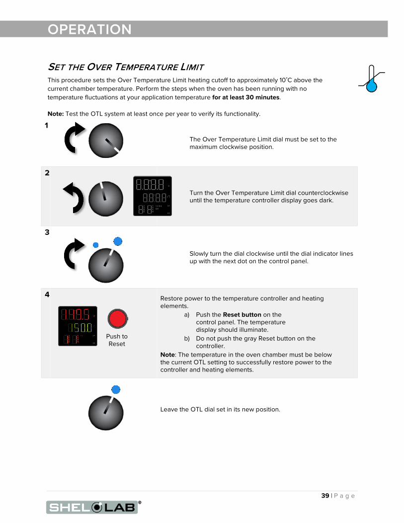
SET THE OVER TEMPERATURE LIMIT This procedure sets the Over Temperature Limit heating cutoff to approximately 10˚C above the current chamber temperature. Perform the steps when the oven has been running with no temperature fluctuations at your application temperature for at least 30 minutes.
Note: Test the OTL system at least once per year to verify its functionality.
1
The Over Temperature Limit dial must be set to the maximum clockwise position.
2
Turn the Over Temperature Limit dial counterclockwise until the temperature controller display goes dark.
3
Slowly turn the dial clockwise until the dial indicator lines up with the next dot on the control panel.
4 Restore power to the temperature controller and heating elements.
a) Push the Reset button on the control panel. The temperature display should illuminate.
b) Do not push the gray Reset button on the controller.
Note: The temperature in the oven chamber must be below the current OTL setting to successfully restore power to the controller and heating elements.
Leave the OTL dial set in its new position.
Push to Reset

40 | P a g e
OPERATION
Over Temperature Limit Activation Conditions
• The current temperature set point is above or near the High Limit cutoff setting. The High Limit should be set at least 10°C above the highest intended temperature of your heating application.
• A heat source in the oven chamber is pushing the oven temperature above the limit setting.
• Significant outgassing in the chamber may be interfering with the measured temperature.
• Attempting to heat a significant mass of product or samples may be triggering a temperature overshoot.
• The main controller circuitry or sensor probe have failed.
If you suspect an ignition event in the oven chamber or hardware failure, turn off the oven and wait for the oven to cool to room temperature before opening chamber door. Contact Technical Support for assistance.
End of procedure

41 | P a g e
OPERATION
DATA PORTS
9-Pin Port
The 9-pin RS485 data port, located on the back of the oven, connects to the oven temperature controller. The port is primarily intended for updating the controller software but can be used for data logging and graphical profile programming. Accessing the controller with a computer requires a 9-pin RS485-to-USB converter cable and driver software.
Applications and Utility Software
• National Instrument LabView and Watlow Specview — Temperature monitoring and data logging in graphical user interface environments.
• Watlow’s EZ Zone™ Configurator — Programming heating profiles in a drop-down menu environment. Configurator can also be used to copy and save the controller configuration file, which includes the currently programmed heating profiles.
o Configurator is available for free on the Watlow website.

42 | P a g e
OPERATION

43 | P a g e
USER MAINTENANCE
Warning: Disconnect the unit from its power supply prior to maintenance or service.
Avertissement: Avant d'effectuer toute maintenance ou entretien de cet appareil, débrancher le cordon secteur de la source d'alimentation.
CLEANING AND DISINFECTING If a hazardous material or substance has spilled in the unit, immediately initiate your site Hazardous Material Spill Containment protocol. Contact your local Site Safety Officer and follow instructions per the site policy and procedures.
• Periodic cleaning is required.
• Do not use spray on cleaners or disinfectants. These can leak through openings and coat electrical components.
• Do not use cleaners or disinfectants that contain solvents capable of harming paint coatings or stainless steel surfaces. Do not use chlorine-based bleaches or abrasives, these will damage the chamber liner.
• Consult with the manufacturer or their agent if you have any doubts about the compatibility of decontamination or cleaning agents with the parts of the equipment or with material contained in it.
Warning: Exercise caution if cleaning the unit with alcohol or flammable cleaners. Always allow the unit to cool down to room temperature prior to cleaning and make sure all cleaning agents have evaporated or otherwise been completely removed prior to putting the unit back into service.
Avertissement: Soyez prudent lorsque vous nettoyez l'appareil avec de l'alcool ou des produits de nettoyage inflammables. Laissez toujours refroidir l'appareil à la température ambiante avant le nettoyage et assurez-vous que tous les produits de nettoyage se sont évaporés ou ont été complètement enlevés avant de remettre l'appareil en service.
Cleaning
1. Remove all removable chamber accessory items (shelves, racks, and any additional items), if present.
1. Clean the chamber interior with a mild soap and water solution, including all corners.
2. Take special care when cleaning around the temperature sensor probes. Do not clean the probes.
3. Clean all removable accessories and components.
4. Rinse the chamber surfaces and shelving with distilled water and wipe dry with a soft cloth. Do not use deionized water.
• Deionized water is an aggressive solvent that will attack most metals. Never use deionized water to clean your oven, even if it is readily available in your laboratory or production workspace.

44 | P a g e
USER MAINTENANCE
Disinfecting
Disinfect the oven if algae, mold, bacteria, or other biological contaminants are an issue. For maximum effectiveness, disinfection procedures are typically performed after cleaning. Keep the following points in mind:
• Turn off and unplug the unit to safeguard against electrical hazards.
• Disinfect the oven chamber using commercially available disinfectants that are non-corrosive, non-abrasive, and suitable for use on stainless steel and glass surfaces. Contact your local Site Safety Officer for detailed information on which disinfectants are compatible with your applications.
• If permitted by your protocol, remove all interior accessories (any shelving and other non-attached items) from the chamber when disinfecting.
• Disinfect all surfaces in the chamber, making sure to thoroughly disinfect the corners. Exercise care to avoid damaging the sensor probes.
• When disinfecting external surfaces, use disinfectants that will not damage painted metal, glass, and plastic.
MAINTAINING ATMOSPHERIC INTEGRITY Periodically, inspect the door latch, trim, catch, and gasket for signs of deterioration. Failure to maintain the integrity of the door system shortens the lifespan of the unit.
The gasket should be replaced if it is dry, cracked, or otherwise showing a loss of elasticity.
ELECTRICAL COMPONENTS Electrical components do not require maintenance. If the oven fails to operate as specified, please contact your distributor or Technical Support for assistance.
VACUUM PUMP MAINTENANCE Refer to the operation manual supplied with your vacuum pump for recommended maintenance routines such as oil levels, replacement of sorbent charge, and exhaust filter change outs. Contact your vacuum pump supplier if you do not have an operation manual.

45 | P a g e
USER MAINTENANCE CALIBRATE THE TEMPERATURE DISPLAY Note: Performing a temperature display calibration requires a temperature reference device. Please see the Reference Sensor Devices entry on page 7 for device requirements.
Temperature calibrations match the temperature display to the actual shelving temperature inside the oven chamber. The actual shelving temperature is supplied by a reference sensor device. Calibrations compensate for software drifts in the controller as well as deviations caused by the natural material evolution of the sensor probe in the heated chamber space. Calibrate as often as required by your laboratory or production protocol, or regulatory compliance schedule. Always calibrate to the industry or regulatory standards required for your application.
The manufacturer recommends calibrating at the constant set point temperature of your application or at the median of your multi-step set heating profile.
Suggested Temperature Calibration Set Up
Continued on next page
1.
Introduce a thermocouple probe from a reference device into the oven chamber using a feedthrough secured to the KF-25 port on the back of the oven.
2.
Use the KF-25 clamp included with the oven to secure the feedthrough and probe, sealing the port.
3. The thermocouple probe ends must be in direct
contact with the shelving. The probes may be taped to the shelves using heat-resistant non-stick tape. Use the tape to secure any loose wiring.
If using a single thermocouple probe, place the probe on the shelving as close as possible to the geometric center of the chamber.
4. SET VACUUM
Evacuate the chamber to the vacuum level of your application or baking process.
The chamber must be under vacuum in order to perform an accurate temperature calibration.

46 | P a g e
Begin Calibration
USER MAINTENANCE 5. Heat up and stabilization period: The oven temperature must be stable and under vacuum in order to perform an accurate calibration. The temperature is considered stabilized when the oven chamber has operated at your calibration temperature for at least one hour with no fluctuations greater than the specified stability of the oven (see the Unit Specifications chapter).
Figure 3: Oven Chamber Heat Up and Stabilization Phases
Continued on next page
Suggested Calibration Procedure
1 Once the chamber has stabilized, compare the reference temperature device and chamber temperature display readings.
• If the readings are the same, or the difference
between the two (2) falls within the acceptable range of your protocol, the display is accurately showing the chamber temperature. The Temperature Calibration procedure is now complete.
• See Step 2 if a difference falls outside the acceptable range of your protocol.
Reference Device
2 The display requires a calibration adjustment.
• The difference between the reference device and the display is an offset value.
• Examples of offset values:
Reference Sensor Reading
Oven Temp Display
Offset Value
152.0°C 150°C 2
149.1°C 150°C -0.9
148.0°C 150°C -2
• Note the offset value for use in Step 5.
Reference Device
150°C
Start
Required Stability Period 1 Hour Minimum
Heat Up to 150°C:
~120 Minutes
Fluctuations (Exaggerated)

47 | P a g e
USER MAINTENANCE
Continued on next page
Calibration Continued
3 Place the controller display in the Operations menu.
a. Press and hold both the Up and Down arrow buttons simultaneously for approximately 3 seconds.
b. Release the buttons when “A1” appears on the top display line and “oPEr” appears in the mid display line.
Operations Menu
4 Advance through the Operations menu to the Temperature Calibration offset parameter.
a. Push the green Advance button repeatedly until
“i.CA” appears on the green mid display line and a number value on the red top line.
5
Adjust the number value in the top display to match the offset value from step 2, using the arrow buttons.
6 Save the calibration offset and return to the homepage.
a. Push the Reset button repeatedly until the display shows the homepage.
• The oven will begin to heat or passively cool to
reach the current set point using the offset display value for the current temperature.
7
Allow the oven to stabilize after achieving the temperature set point using the offset display value.

48 | P a g e
USER MAINTENANCE
End of procedure
Calibration Continued
8
Once the chamber has stabilized, compare the reference temperature device and oven temperature display readings.
a. If the readings are the same or the difference between the two falls within the acceptable range of your protocol, the display is accurately showing the chamber temperature. The temperature calibration procedure is now complete.
b. See step 9 if a difference falls outside the acceptable range of your protocol again.
Reference Device
9
Repeat steps 2 – 8 up to two more times. • Three (3) calibration attempts may be required to
successfully calibrate ovens that are more than ± 2°C out of calibration.
Reference Device
If the temperature reading difference still falls outside your protocol after three calibration attempts, contact your distributor or Technical Support for assistance.

49 | P a g e
UNIT SPECIFICATIONS
The SVAC9-2 is a 230 AC voltage, single-phase unit. Please refer to the oven data plate for individual electrical specifications.
Technical data specified applies to units with standard equipment at an ambient temperature of 25°C and a voltage fluctuation of ±10%. The temperatures specified are determined in accordance to factory standard following DIN 12880 respecting the recommended wall clearances of 10% of the height, width, and depth of the inner chamber. All indications are average values, typical for units produced in the series. We reserve the right to alter technical specifications at all times.
WEIGHT Shipping Net Weight
985 lb / 447 kg 492.0 lb / 223.0 kg
DIMENSIONS Inches
Exterior W × D × H Interior W × D × H
38.1 x 46.8 x 63.9 in 28.0 x 24.0 x 24.0 in
Millimeters
Exterior W × D × H Interior W × D × H
965 x 1189 x 1624 mm 711 x 610 x 610 mm
CAPACITY Cubic Feet Liters
9.3 264.0
SHELF CAPACITY BY WEIGHT Per Shelf Total
75.0 lb / 34.0 kg 225.0 lb / 102.0 kg

50 | P a g e
UNIT SPECIFICATIONS
TEMPERATURE PERFORMANCE
Range and Uniformity
Operating Range Uniformity
Ambient +15° to 220°C ±6% of Set Point
Stability
@80°C @150°C @220°C
± 0.2°C ± 0.2°C ± 0.3°C
Heat up Times from Ambient (25°C)
To 80°C To 150°C To 220°C
80 minutes 130 minutes 180 minutes
POWER Model AC Voltage Amperage Frequency Phase
SVAC9-2 230 20.0 50/60 Hz 1

51 | P a g e
REPLACEMENT PARTS
Description Parts Number
Adjustable Feet
2700506
Oil Tray, for Vacuum Pump
5402470
Shelf, SVAC9-2
5680562
Shelf Clip
1250510
Viton O-Ring Gasket (60 inches OD, 3 inches ID) for Oven Door
3450579
Viton O-Ring Gasket (60 inches OD, 3 inches ID) for Door Window
3450560
If you have the Part Number for an item, you may order it directly from Sheldon Manufacturing by calling 1-800-322-4897 extension 3. If you are uncertain that you have the correct Part Number, or if you need that specific item, please contact Sheldon Technical Support for help at 1-800-322-4897 extension 4 or (503) 640-3000. Please have the model number and serial number of the unit ready, as Tech Support will need this information to match your oven with its correct part.

P.O. Box 627 Cornelius, OR 97113
USA
[email protected] sheldonmanufacturing.com
1-800-322-4897 (503) 640-3000
FAX: 503 640-1366