operation & 2620 spe africa om guidelines 06 mr.pdf
TRANSCRIPT

Supported by:
Best Practice Guidelines Africa edition
MaintenanceOperation &

GET.invest is supported by
Mobilising Investments in Emerging Markets
Pict
ure
cre
dit
s ©
All
ian
ce f
or
Ru
ral E
lect
rifi
cati
on
www.get-invest.eu @GET_invest GET.invest
MARKET INFORMATIONWe provide investors, project and business developers with
critical market intelligence for informed decisions.
ACCESS TO FINANCEGET.invest’s Finance Catalyst delivers advisory services for
the preparation of decentralised renewable energy projects
and connects your business to financing.
NETWORKING & INFORMATION EVENTSOur information and networking sessions stimulate
cooperation and new business development.
FUNDING DATABASENavigate the complex landscape of funding sources and find
out which instrument suits your renewables project or business.

Operation & Maintenance Best Practice Guidelines / Africa edition 3
Foreword
Welcome to the Africa edition of the Operation and Maintenance (O&M) Best Practice Guidelines. Building on Version 4.0 of SolarPower Europe’s O&M Best Practice Guidelines, this edition is adapted to the Sub-Saharan African context. It is a joint effort between SolarPower Europe and ten African solar and renewable energy industry associations, and supported by GET.invest, a European programme which mobilises investments in decentralised renewable energy, supported by the European Union, Germany, Sweden, the Netherlands and Austria.
Many Sub-Saharan African markets have already added the first tens and, in some cases, hundreds of MWs of solar photovoltaic (PV) capacity, with significant growth expected in the coming years. As markets develop, concerns increase around the long-term reliability and performance of solar assets, as they strongly affect project bankability and return on investments. As power plants age, the industry has realised that proper “health care” is indispensable for power plants to meet performance expectations. Today, O&M has become a standalone segment within the solar industry, with an increasing number of solar companies in Africa providing specialised services. Yet there are still significant quality discrepancies between services from different providers.
To address these challenges, SolarPower Europe joined forces with GET.invest and ten African solar and renewable energy associations from Ghana, Ivory Coast, Kenya, Mozambique, Nigeria, South Africa, Tanzania, Zambia and Zimbabwe to develop the Africa edition of the O&M Best Practice Guidelines. Our joint African-European O&M Task Force was launched in September 2020, assembling 30 leading solar experts from Africa and Europe. The kick-off meeting was followed by a series of online working meetings, in which we updated Version 4.0 of SolarPower Europe’s O&M Best Practice Guidelines, in order to reflect the market and business conditions in Africa. The result is a guide that we hope will help African solar stakeholders increase quality in the O&M segment. This document is aimed at O&M service providers, as well as other parties involved in the operation of solar power plants, such as owners and investors, lenders, technical advisors and data-related service providers. It will help establish common standards and increase transparency in the sector. It is also worth noting that solar O&M is especially value intensive, as a segment that supports many local jobs, and drives important solar innovations, notably in the field of digitalisation.
In the Africa edition, all chapters of the original document have been thoroughly reviewed and revised with a focus on unique aspects of Sub-Saharan Africa. A key objective was to make sure that this edition will also be useful for operators of small and medium-size C&I installations. For this, we have tweaked the requirements for smaller installations where necessary, such as for simplified Documentation Management Systems or Monitoring Tools. We have also considered that water scarcity may be an issue in many regions of Africa. This has certain repercussions for operators’ environmental and social responsibilities, and operators are encouraged to reduce the amount of water used for module cleaning through various innovations. Finally, we introduced a new chapter on “O&M for standalone solar systems with storage”, a chapter to assist in the application of best practices to off-grid systems. These are only some examples from the many updates that we implemented in order to make these Guidelines as useful as possible for solar businesses in Sub-Saharan Africa.
We encourage all solar operators in the African region to consider adopting these Guidelines and reach out to their respective industry associations with any questions or suggestions.
WALBURGA HEMETSBERGER Chief Executive Officer, SolarPower Europe
DAVID ACHI Association of Renewable Energy Professionals of Côte d'Ivoire (APERCI)
SEGUN ADAJU President, Renewable Energy Association of Nigeria (REAN)
ENOCH AGYEPONG Executive Director, Renewable Energy Association of Ghana (REAG)
RICARDO COSTA PEREIRA President, Renewable Energy Association of Mozambique (AMER)
NIVESHEN GOVENDER Chief Operating Officer, South African Photovoltaic Industry Association (SAPVIA)
KAMAL GUPTA Chairman, Kenya Renewable Energy Association (KEREA)
GEOFFREY KAILA President, Solar Industry Association of Zambia (SIAZ)
MATTHEW MATIMBWI Executive Secretary, Tanzania Renewable Energy Association (TAREA)
ISAIAH D. NYAKUSENDWA President, Renewable Energy Association of Zimbabwe (REAZ)
JOHN VAN ZUYLEN CEO, African Solar Industry Association (AFSIA)

Operation & Maintenance Best Practice Guidelines / Africa edition 4
Chair of the SolarPower Europe Lifecycle Quality Workstream: Adele Ara, Lightsource bp.
Vice-Chairs of the SolarPower Europe Lifecycle Quality Workstream: Alden Lee, ABO Wind; Ralph Gottschalg, Fraunhofer CSP.
Coordinator of the African-European O&M Task Force: Máté Heisz, SolarPower Europe.
Contact: [email protected].
Contributors of the Africa edition: Lande Abadu, Renewable Energy Association of Nigeria (REAN); David Achi, Association of Renewable Energy Professionals of Côte d'Ivoire (APERCI); Segun Adaju, Renewable Energy Association of Nigeria (REAN); Enoch Agyepong, Renewable Energy Association of Ghana (REAG); Thomas C. Sauer, EXXERGY; Ricardo Costa Pereira, Renewable Energy Association of Mozambique (AMER); Emmett Costel, Renewable Energy Association of Mozambique (AMER); Paolo di Ciaccio, Eni; Ralph Gottschalg, Fraunhofer CSP; Niveshen Govender, South African Photovoltaic Industry Association (SAPVIA); Kamal Gupta, Kenya Renewable Energy Association (KEREA); Máté Heisz, SolarPower Europe; Bernhard Höfner, ABO Wind; Geoffrey Kaila, Solar Industry Association of Zambia (SIAZ); Hadyr Koumakpai, JA Solar/African Solar Industry Association (AFSIA); Juan Luis Agarrado, 3E; Matthew Matimbwi, Tanzania Renewable Energy Association (TAREA); Joyce Naa Oturku, Renewable Energy Association of Ghana (REAG); Joseph Nader, TÜV Rheinland Middle East; Chanda Nxumalo, South African Photovoltaic Industry Association (SAPVIA); Isaiah D. Nyakusendwa, Renewable Energy Association of Zimbabwe (REAZ); Eliane Pohl, Greenbyte; Geoffrey R. John, Tanzania Renewable Energy Association (TAREA); Ali Rahmati, Fronius; Wolfgang Rosenberg, TCO Solar; John Shija, BayWa r.e.; Taona Sylveter Jakachira, Renewable Energy Association of Zimbabwe (REAZ); Guillaume Tixier, 3E; Gary Wiltshire, Logos Industries/Renewable Energy Association of Mozambique (AMER); Adam Terry, South African Photovoltaic Industry Association (SAPVIA).
Supported by: GET.invest. GET.invest is a European programme which supports investments in decentralised renewable energy. The programme targets private sector business and project developers, financiers and regulators to build sustainable energy markets in developing countries. Services include market information, a funding database, matchmaking events and access-to-finance advisory. The programme is supported by the European Union, Germany, Sweden, the Netherlands, and Austria, and works closely with initiatives and business associations in the energy sector. For further information about GET.invest, please see www.get-invest.eu or contact [email protected].
In strategic partnership with: African Solar Industry Association (AFSIA), Renewable Energy Association of Mozambique (AMER), Association of Renewable Energy Professionals of Côte d'Ivoire (APERCI), Kenya Renewable Energy Association (KEREA), Renewable Energy Association of Ghana (REAG), Renewable Energy Association of Nigeria (REAN), Renewable Energy Association of Zimbabwe (REAZ), South African Photovoltaic Industry Association (SAPVIA), Solar Industry Association of Zambia (SIAZ), Tanzania Renewable Energy Association (TAREA).
Acknowledgements: SolarPower Europe would like to extend special thanks to all the Task Force members that contributed to this report with their knowledge and experience, as well as GET.invest for supporting this project. This work would never have been realised without their continuous support.
Project Information: The Africa edition of the O&M Best Practices Guidelines of SolarPower Europe reflects the experience and views of a considerable share of the African and European O&M industry today. It is based on Version 4.0 of SolarPower Europe’s O&M Best Practice Guidelines and has been adjusted to the Sub-Saharan African regional context in a joint effort between SolarPower Europe and ten African industry associations. The development of the Africa edition was supported by GET.invest, a European programme supported by the European Union, Germany, Sweden, the Netherlands, and Austria.
Disclaimer: Adherence to the SolarPower Europe O&M Best Practices Guidelines report and its by-products is voluntary. The contents of this publication do not necessarily reflect the views of GET.invest and its donors. Any stakeholders that wish to adhere to the O&M Best Practices Guidelines are responsible for self-certifying that they have fulfilled the guide requirements through completing the self-certification procedure offered by the “Solar Best Practices Mark” (www.solarbestpractices.com). This report has been prepared by SolarPower Europe, in collaboration with ten African renewable energy associations, and with the support of GET.invest. It is being provided to the recipients for general information purposes only. Nothing in it should be interpreted as an offer or recommendation of any products, services or financial products. This report does not constitute technical, investment, legal, tax or any other advice. Recipients should consult with their own technical, financial, legal, tax or other advisors as needed. This report is based on sources believed to be accurate. However, SolarPower Europe, GET.invest and the other supporters of this report do not warrant the accuracy or completeness of any information contained in this report. SolarPower Europe, GET.invest and the other supporters of this report assume no obligation to update any information contained herein. SolarPower Europe, GET.invest and the other supporters of this report will not be held liable for any direct or indirect damage incurred by the use of the information provided and will not provide any indemnities.
Design: Onehemisphere, Sweden. Email: [email protected].
ISBN: 9789464073461.
Published: March 2021.
GET.invest is supported by
Operation & Maintenance Best Practice Guidelines / Africa edition 5
Members of the African-European O&M Task Force:
Sponsor members of SolarPower Europe:
Operation & Maintenance Best Practice Guidelines / Africa edition 6
6.3. Performance analysis and improvement 45
6.4. Optimisation of O&M 45 6.5. Power plant controls 45 6.6. Power Generation Forecasting 46 6.7. Grid code compliance 46 6.8. Management of change 47 6.9. Power plant security 48
7 Power Plant Maintenance 49
7.1. Preventive Maintenance 49 7.2. Corrective Maintenance 51 7.3. Predictive Maintenance 52 7.4. Extraordinary Maintenance 53 7.5. Additional services 54
8 Revamping and Repowering 56
8.1. Definition and rationale of revamping and Repowering 56
8.2. Module Repowering 56 8.3. Inverter Repowering 58 8.4. General Repowering considerations 59
9 Spare parts management 61 10 Data and monitoring requirements 64
10.1. Data loggers 65 10.2. Monitoring portal 66 10.3. Data format 67 10.4. Configuration 67 10.5. Interoperability 67 10.6. Internet connection and
Local Area Network 68 10.7. Data ownership and privacy 70 10.8. Cybersecurity 70 10.9. Types of data collected through
the monitoring system 71 10.9.1. Irradiance measurements 71 10.9.2. Module temperature measurements 72 10.9.3. Local meteorological data 72 10.9.4. String measurements 72 10.9.5. Inverter measurements 73 10.9.6. Energy meter 73 10.9.7. Control settings 74 10.9.8. Alarms 74 10.9.9. AC circuit/protection relay 74 10.10. Data collected by specialised PV
module field inspections 74 10.10.1. Infrared thermography (IR) 75
Table of contents
Foreword 3 Table of contents 6 List of tables and figures 8 List of abbreviations 9 Executive summary 10 1 Introduction 13
1.1. Rationale, aim and scope 13 1.2. How to benefit from this document 151.3. Stakeholders and roles 16 1.4. Costs and benefits of best practices 19
2 Definitions 20 3 Environment, Health & Safety 26
3.1. Environment and social 26 3.2. Health and Safety 28
4 Personnel & training 31 5 Technical Asset Management 32
5.1. Technical reporting 32 5.2. Site visits and non-intrusive
inspections 34 5.3. Lifetime conformity assessment 34 5.4. Management of ancillary
service providers 34 5.5. Interface with local energy
authorities & regulatory compliance 35 5.6. Warranty management 37 5.7. Insurance claims 38 5.8. Contract management
(operational contracts) 38 5.9. Asset optimisation (technical) 39 5.10. Environmental management 39 5.11. Health & safety management 39 5.12. Force majeure
(pandemic) management 39 6 Power Plant Operation 40
6.1. Documentation Management System (DMS) 40
6.2. Plant performance monitoring and supervision 41

Operation & Maintenance Best Practice Guidelines / Africa edition 7
10.10.2. I-V curve tracing on-site 75 10.10.3. Electroluminescence (EL)
imaging on-site 75 10.10.4. Flourescence imaging 76 10.10.5. Magnetic Field Imaging (MFI) 76 10.10.6. Soiling measurements 77
11 Key Performance Indicators 78
11.1. PV power plant data 79 11.1.1. Raw data measurements for
performance calculation 79 11.2. PV power plant KPIs 79 11.2.1. Reference yYield 79 11.2.2. Specific yield 79 11.2.3. Performance ratio 80 11.2.4. Temperature-corrected
performance ratio 80 11.2.5. Expected yield 82 11.2.6. Energy Performance Index 82 11.2.7. Technical availability or uptime 82 11.2.8. Technical tracker availability
or tracker uptime 83 11.3. O&M contractor KPIs 84 11.3.1. Acknowledgement time 84 11.3.2. Intervention time 84 11.3.3. Response time 84 11.3.4. Resolution time 84 11.3.5. Reporting 84 11.3.6. O&M contractor experience 85 11.3.7. Schedule attainment 85 11.3.8. Preventive vs corrective
maintenance ratio 85 11.4. PV power plant/O&M
contractor KPIs 85 11.4.1. Contractual availability 85 11.4.2. Contractual tracker availability 87 11.4.3. Energy-based availability 87
12 Contractual framework 90
12.1. Scope of the O&M contract 90 12.2. O&M contract fee 93 12.3. Contractual guarantees
and price adjustments 93 12.3.1. Availability guarantee 93 12.3.2. Response time price adjustment 93 12.4. Bonus schemes and
liquidated damages 94 12.5. Service standards 95 12.6. O&M contractors’ qualification 95 12.7. Responsibility and accountability 95
12.8. Spare parts management 96 12.9. Power plant remote monitoring 96 12.10. Reporting 96
13 Innovations and trends 97
13.1. Smart PV power plant monitoring and data-driven O&M 97
13.1.1. Advanced aerial thermography 98 13.1.2. Automated plant performance
diagnosis 100 13.1.3. Predictive maintenance for
optimised hardware replacement 101 13.1.4. PV plant yield forecasting 102 13.1.5. Internet of Things (IoT) and
auto-configuration 103 13.1.6. Future best practices in document
management systems 104 13.2. Retrofit coatings for PV modules 104 13.2.1. Anti-soiling coatings 104 13.2.2. Anti-reflective coatings 105 13.3. Waterless cleaning of PV modules 106
14 O&M for standalone solar installations with storage 107
14.1. Environment, Healthy & Safety 107 14.2. Monitoring & reporting 108 14.3. Maintenance 109 14.4. Contractual recommendations
for standalone PV systems 111 References 119 Annex 120
a. Applicable international standards for solar O&M 113
b. Proposed skill matrix for O&M personnel 114
c. Documentation set accompanying the solar PV plant 115
d. Important examples of input records in the record control 117
e. Annual maintenance plan: On-grid 119 f. Annual maintenance plan: Off-grid 124
Table of contents
Operation & Maintenance Best Practice Guidelines / Africa edition 8
Table 1: Proposed indicators/values required for the reporting 33
Table 2: Examples for additional maintenance services 55
Table 3: Minimum list of spare parts (non-exhaustive) 63
Table 4: Examples of data integration options 68
Table 5: Pros and cons of different types of monitoring connections 69
Table 6: Overview of different types of Key Performance Indicators and their purposes 88
Table 7: Examples for additional maintenance services and general market trends 92
Table 8: Examples for fault classes and corresponding minimum response times 94
Table 9: Aerial IR thermography – post-processing subtasks 99
Table 10: Methods suggested for the collection of reference yield 109
Table 11: Incidents covered by O&M service agreements for distributes solar systems 111
Figure 1: Overview of a selection of applicable standards for O&M 14
Figure 2: Roles and responsibilities by different stakeholders in the field of O&M 18
Figure 3: Case study of a yield review of a challenged PV power plant project 20
Figure 4: Overview of the most important tasks in power plant operation 42
Figure 5: Support levels in fault management 44
Figure 6: Overview of the different types of power plant maintenance 50
Figure 7: Differences between revamping and repowering and their main drivers 57
Figure 8: Energy flow in a grid-connected photovoltaic system with parameters, yields and losses 64
Figure 9: Example UV-Flourescence images after a severe hail-storm 76
Figure 10: Examples of Magnetic Field Imaging (MFI) 77
Figure 11: Overview of different types of KPIs 78
Figure 12: Various periods of time for the calculation of the technical availability 83
Figure 13: Acknowledgement time, intervention time, response time, resolution time 84
Figure 14: Various periods of time for the calculation of contractual availability 86
Figure 15: Overview of the six template contracts developed under the Open Solar Contracts initiative 91
Figure 16: Data mining foundations 98
Figure 17: Automated plant performance diagnosis 101
Figure 18: Predictive maintenance for optimised hardware replacement 101
List of tables
Box 1: Preserving and enhancing the Natural Capital values of large-scale solar plants 27
Box 2: Interpreting Performance Ratio 81
List of boxes
List of figures
Operation & Maintenance Best Practice Guidelines / Africa edition 9
AC Alternating Current AGM Absorbed Glass Mat batteries AMP Annual Maintenance Plan AMR Automatic Meter Reading AMS Annual Maintenance Schedule API Application Programming Interface CCTV Closed Circuit Television CMMS Computerised Maintenance Management System COD Commercial Operation Date CSMS Cybersecurity Management System DC Direct Current DMS Document Management System DOR Division of Responsibility DSCR Debt Service Coverage Ratio DSL Digital Subscriber Line EH&S Environment, Health and Safety EMS Energy Management System EPC Engineering, Procurement, Construction EPI Energy Performance Index ERP Enterprise Resource Planning System ESIA Environmental, Social Impact Assessment ESMP Environmental, Social Management Plan ESS Energy Storage System FAC Final Acceptance Certificate FIT Feed-in tariff FTP File Transfer Protocol GPRS General Packet Radio Service H&S Health and Safety HV High Voltage IEC International Electrotechnical Commission IECRE IEC System for Certification to Standards Relating to Equipment for Use in Renewable Energy Applications IGBT Insulated-Gate Bipolar Transistors IPP Independent Power Producer IR Infrared IRENA International Renewable Energy Agency
List of abbreviations
ISO International Organization for Standardization KPI Key Performance Indicator kW kilowatt kWh kilowatt-hour kWp kilowatt-peak LAN Local Area Network LCOE Levelised Cost of Electricity LIB Lithium-Ion Batteries LTE-M Long-power Wide-area Network LPWAN Long Term Evolution, category M1 LV Low voltage MAE Mean Absolute Error MIT Minimum Irradiance Threshold MPPT Maximum Power Point Tracking MV Medium Voltage MW Megawatt O&M Operation and Maintenance OEM Original Equipment Manufacturer OS Operating System PAC Provisional Acceptance Certificate POA Plane of Array PPA Power Purchase Agreement PPE Personal Protective Equipment PR Performance Ratio PV Photovoltaic RMSE Root Mean Square Error ROI Return on Investment RPAS Remotely Piloted Aircraft System (drone) SCADA Supervisory Control And Data Acquisition SLA Service-level Agreement SPV Special Purpose Vehicle STC Standard Test Conditions (1000 W/M2, 25°C) TF Task Force UPS Uninterruptible Power Supply VLA Vented Lead Acid Batteries VRLA Valve-Regulated Lead-Acid batteries
Operation & Maintenance Best Practice Guidelines / Africa edition 10
insecticides. In Africa, water scarcity should be considered in certain arid regions and it is important to have a plan to avoid local conflicts over water.
In many situations, solar plants offer an opportunity to provide for agriculture and are a valuable natural habitat for plants and animals alongside the primary purpose of power production. Solar plants are electricity generating power stations and have significant hazards present which can result in injury or death. Risks should be reduced through proper hazard identification, careful planning of works, briefing of procedures to be followed, documented and regular inspection, and maintenance. Personnel training and certification and personal protective equipment are required for several tasks. Almost all jobs have some safety requirements such as fall protection for work at heights and electrical arc-flash, lock-out tag-out, and general electrical safety for electrical work; eye and ear protection for ground maintenance.
Personnel & training
It is important that all O&M personnel have the relevant experience and qualifications to perform the work in a safe, responsible and accountable manner. These Guidelines contain a skills’ matrix template that helps to record skills and identify gaps.
Technical asset management
Technical Asset Management encompasses support activities to ensure the best operation of a solar power plant or a portfolio, i.e. to maximise energy production, minimise downtime and reduce costs. In the African context, especially in the C&I and residential segments, Technical Asset Management, Power plant operation and Power plant maintenance, is often assumed by the same entity, the installer. However, in cases where these roles are separated, and the technical asset manager and the O&M contractor are separate entities, close coordination and information sharing between the two entities is indispensable. Technical Asset Management also includes ensuring that the operation of the PV plant complies with national and local regulations and contracts, and also advising the asset owner on technical asset optimisation. For more information about commercial and financial Asset Management (an increasingly standalone segment in Europe), please refer to
Executive summary
Many Sub-Saharan African markets have already added the first tens and, in some cases, hundreds of MW of solar capacity, with significant growth expected in the coming years. As markets develop, concerns related to long-term reliability and performance of solar assets rise, as they strongly affect project bankability and return on investment. Operation and Maintenance (O&M) has become a standalone segment within the solar industry and it is widely acknowledged by all stakeholders that high-quality O&M services mitigate potential risks, improve the Levelised Cost of Electricity (LCOE) and Power Purchase Agreement (PPA) prices, and positively impact the return on investment (ROI). Responding to the discrepancies that exist in today’s solar O&M market, the Africa edition of the O&M Best Practice Guidelines makes it possible for all to benefit from the experience of leading African and European experts in the sector and increase the level of quality and consistency in O&M. These Guidelines are meant for O&M contractors as well as installers, owners, investors, financiers, monitoring tool providers, technical consultants and all interested stakeholders in Sub-Saharan Africa. In this Africa-specific edition, the requirements presented in SolarPower Europe’s O&M Best Practice Guidelines Version 4.0 have been adapted to match the Sub-Saharan African market context. Thus, for example, smaller scale installations in the 10s and 100s of kW scale, such as Commercial & Industrial (C&I) installations, are in the scope of these Guidelines.
This document begins by contextualising O&M, explaining the roles and responsibilities of various stakeholders such as the installer of the O&M provider, and by presenting an overview of technical and contractual terms to achieve a common understanding of the subject. It then walks the reader through the different components of O&M, classifying requirements into “minimum requirements”, “best practices” and “recommendations”.
Environment, health & safety
Environmental problems are normally avoidable through proper plant design and maintenance, but where issues do occur, the O&M contractor must detect them and respond promptly. Environmental compliance may be triggered by components of the PV system itself, such as components that include hazardous materials and by-products that may be used by the O&M contractor such as herbicides and

Operation & Maintenance Best Practice Guidelines / Africa edition 11
SolarPower Europe’s Asset Management Best Practice Guidelines, which can be downloaded from www.solarpowereurope.org.
Power plant operation
Operation is about remote monitoring, supervision and control of the PV power plant or portfolio and it is an increasingly active exercise as grid operators require more and more flexibility from solar power plants. Power plant operation also involves liaising with or coordination of the maintenance team. A proper PV plant documentation management system is crucial for Operations. A list of documents that should be included in the as-built documentation set accompanying the solar PV plant (such as PV modules’ datasheets), as well as a list of examples of input records that should be included in the record control (such as alarms descriptions), can be found in the Annex of these Guidelines. Based on the data and analyses gained through monitoring and supervision, the O&M contractor should always strive to improve PV power plant performance. As there are strict legal requirements for security services in most countries, PV power plant security should be ensured by specialised security service providers. Considering that the typical C&I installation size in Africa is in the 10s or 100s of kW scale, this version of the Guidelines proposes adjusted or simplified procedures or solutions, such as the Documentation Management System.
Power plant maintenance
Maintenance is usually carried out on-site by specialised technicians or subcontractors, according to the Operation team’s analyses. A core element of maintenance services, Preventive Maintenance involves regular visual and physical inspections, functional testing and measurements, as well as the verification activities necessary to comply with the operating manuals and warranty requirements. The Annual Maintenance Plan (see an example in Annex b) includes a list of inspections and actions that should be performed regularly. Corrective Maintenance covers activities aimed at restoring a faulty PV plant, equipment or component to a status where it can perform the required function. Extraordinary Maintenance actions, usually not covered by the O&M fixed fee, can be necessary after major unpredictable events in the plant site that require substantial repair works. Additional maintenance
services may include tasks such as module cleaning and vegetation control, which could be done by the O&M contractor or outsourced to specialist providers.
Revamping and repowering
Revamping and repowering are usually considered a part of extraordinary maintenance from a contractual point of view. However, revamping and repowering has a rapidly increasing significance in the solar O&M market around the world, with Africa being no exception to this. It is expected that revamping and repowering will gain traction in Africa in the years to come. Therefore, these Guidelines address them in a standalone chapter. Revamping and repowering are defined as the replacement of old, power production related components within a power plant by new components to enhance the overall performance of the installation. This chapter presents the best practices in module and inverter revamping and repowering and general, commercial considerations to keep in mind before implementation.
Spare parts management
Spare Parts Management is an inherent and substantial part of O&M aimed at ensuring that spare parts are available in a timely manner for Preventive and Corrective Maintenance in order to minimise the downtime of a solar PV plant. As a best practice, the spare parts should be owned by the asset owner while normally maintenance, storage and replenishment should be the responsibility of the O&M contractor. It is considered a best practice not to include the cost of replenishment of spare parts in the O&M fixed fee. However, if the asset owner requires the O&M contractor to bear replenishment costs, the more cost-effective approach is to agree which are “Included Spare Parts” and which are “Excluded Spare Parts”. These Guidelines also include a minimum list of spare parts that are considered essential. In the African context, when setting spare parts’ stocking levels, it needs to be considered that spare parts’ availability may be more limited due to the absence of local representations of manufacturers.
Data and monitoring requirements
The purpose of the monitoring system is to allow supervision of the performance of a PV power plant. Requirements for effective monitoring include
Operation & Maintenance Best Practice Guidelines / Africa edition 12
dataloggers capable of collecting data (such as energy generated, irradiance, module temperature, etc.) of all relevant components (such as inverters, energy meters, pyranometers, temperature sensors) and storing at least one month of data with a recording granularity of up to 15 minutes, as well as a reliable Monitoring Portal (interface) for the visualisation of the collected data and the calculation of KPIs. Monitoring is increasingly employing satellite data as a source of solar resource data to be used as a comparison reference for on-site pyranometers. As a best practice, the monitoring system should ensure open data accessibility in order to enable an easy transition between monitoring platforms and interoperability of different applications. As remotely monitored and controlled systems, PV plants are exposed to cybersecurity risks. It is therefore vital that installations undertake a cyber security analysis and implement a cybersecurity management system. To evaluate monitoring tools it is recommended to refer to the Monitoring Checklist of the Solar Best Practices Mark, which is available at www.solarbestpractices.com. Considering that the typical C&I installation size in Africa is in the 10s or 100s of kW scale, this version of the Guidelines proposes adjusted or simplified procedures or solutions for some requirements, such as the monitoring system functionalities or types of data collected.
Key Performance Indicators
Important KPIs include PV power plant KPIs, directly reflecting the performance of the PV power plant; O&M contractor KPIs, assessing the performance of the O&M service provided, and PV power plant/O&M contractor KPIs, which reflect power plant performance and O&M service quality at the same time. PV power plant KPIs include important indicators such as the Performance Ratio (PR), which is the energy generated divided by the energy obtainable under ideal conditions expressed as a percentage, and Uptime (or Technical Availability) which are parameters that represent, as a percentage, the time during which the plant operates over the total possible time it is able to operate. O&M contractor KPIs include Acknowledgement Time (the time between the alarm and the acknowledgement), Intervention Time (the time between acknowledgement and reaching the plant by a technician) and Resolution Time (the time to resolve the fault starting from the moment of reaching the PV plant). Acknowledgement Time plus Intervention Time are called Response Time, an indicator used for contractual guarantees. The most important KPI which reflects PV
power plant performance and O&M service quality at the same time is the Contractual Availability. While Uptime (or Technical Availability) reflects all downtimes regardless of the cause, Contractual Availability involves certain exclusion factors to account for downtimes not attributable to the O&M Contractor (such as force majeure), a difference important for contractual purposes.
Contractual framework
Although some third-party O&M contractors still provide Performance Ratio guarantees in some cases, it is a best practice to only use Availability and Response Time guarantees, which has several advantages. A best practice is a minimum guaranteed Availability of 98% over a year, with Contractual Availability guarantees translated into Bonus Schemes and Liquidated Damages. When setting Response Time guarantees, it is recommended to differentiate between hours and periods with high and low irradiance levels as well as fault classes, i.e. the (potential) power loss. PR guarantees are more suitable when the installer is the same entity as the O&M provider, which is often the case in Sub-Saharan Africa.
Innovations and trends
O&M contractors are increasingly relying on innovations and more machine and data-driven solutions to keep up with market requirements. The most important trends and innovations shaping today’s O&M market are summarised in this chapter, grouped into three “families”: (1) Smart PV power plant monitoring and data-driven O&M, (2) Retrofit coatings for PV modules, and (3) waterless cleaning for PV modules, which is particularly relevant for arid regions.
O&M for standalone solar installations with storage
This chapter assists in the application of the best practices, detailed in the previous chapters of the document, to standalone off-grid PV plants. All best practices mentioned in these Guidelines could be theoretically applied to the smallest systems, however in off-grid areas there are different priorities. Apart from providing the highest possible care in the most cost-efficient manner to deliver the lowest levelized cost of electricity (LCOE), other objectives are at least as important, like availability of electricity at the moment of demand and ease of maintenance.
Executive summary / continued
Operation & Maintenance Best Practice Guidelines / Africa edition 13
Introduction
1
1.1. Rationale, aim and scope
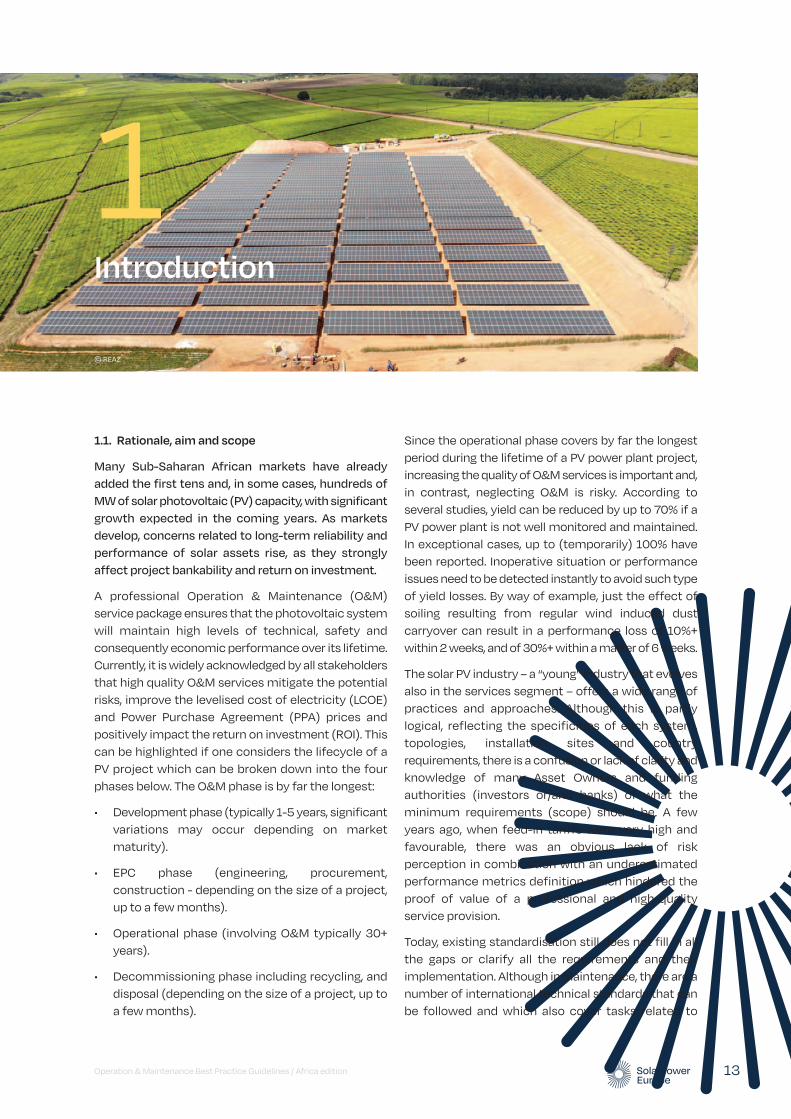
Many Sub-Saharan African markets have already added the first tens and, in some cases, hundreds of MW of solar photovoltaic (PV) capacity, with significant growth expected in the coming years. As markets develop, concerns related to long-term reliability and performance of solar assets rise, as they strongly affect project bankability and return on investment.
A professional Operation & Maintenance (O&M) service package ensures that the photovoltaic system will maintain high levels of technical, safety and consequently economic performance over its lifetime. Currently, it is widely acknowledged by all stakeholders that high quality O&M services mitigate the potential risks, improve the levelised cost of electricity (LCOE) and Power Purchase Agreement (PPA) prices and positively impact the return on investment (ROI). This can be highlighted if one considers the lifecycle of a PV project which can be broken down into the four phases below. The O&M phase is by far the longest:
• Development phase (typically 1-5 years, significant variations may occur depending on market maturity).
• EPC phase (engineering, procurement, construction - depending on the size of a project, up to a few months).
• Operational phase (involving O&M typically 30+ years).
• Decommissioning phase including recycling, and disposal (depending on the size of a project, up to a few months).
Since the operational phase covers by far the longest period during the lifetime of a PV power plant project, increasing the quality of O&M services is important and, in contrast, neglecting O&M is risky. According to several studies, yield can be reduced by up to 70% if a PV power plant is not well monitored and maintained. In exceptional cases, up to (temporarily) 100% have been reported. Inoperative situation or performance issues need to be detected instantly to avoid such type of yield losses. By way of example, just the effect of soiling resulting from regular wind induced dust carryover can result in a performance loss of 10%+ within 2 weeks, and of 30%+ within a matter of 6 weeks.
The solar PV industry – a “young” industry that evolves also in the services segment – offers a wide range of practices and approaches. Although this is partly logical, reflecting the specificities of each system, topologies, installation sites and country requirements, there is a confusion or lack of clarity and knowledge of many Asset Owners and funding authorities (investors or/and banks) of what the minimum requirements (scope) should be. A few years ago, when feed-in tariffs were very high and favourable, there was an obvious lack of risk perception in combination with an underestimated performance metrics definition which hindered the proof of value of a professional and high-quality service provision.
Today, existing standardisation still does not fill in all the gaps or clarify all the requirements and their implementation. Although in Maintenance, there are a number of international technical standards that can be followed and which also cover tasks related to
© REAZ
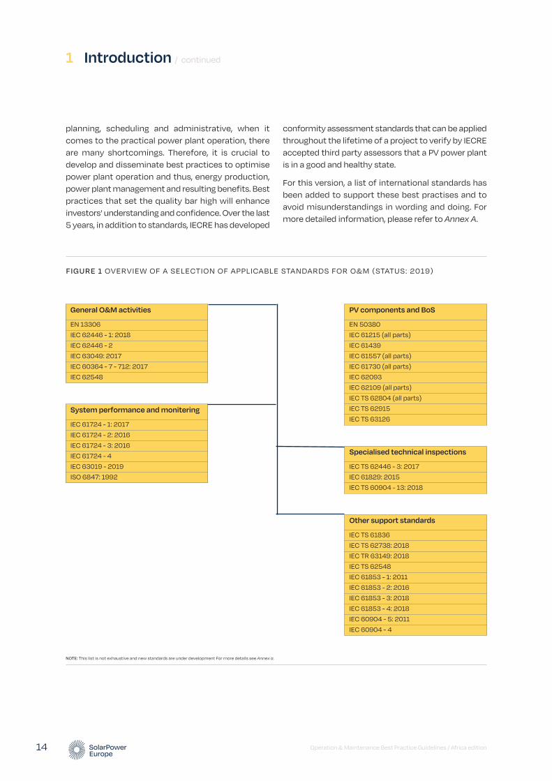
planning, scheduling and administrative, when it comes to the practical power plant operation, there are many shortcomings. Therefore, it is crucial to develop and disseminate best practices to optimise power plant operation and thus, energy production, power plant management and resulting benefits. Best practices that set the quality bar high will enhance investors’ understanding and confidence. Over the last 5 years, in addition to standards, IECRE has developed
conformity assessment standards that can be applied throughout the lifetime of a project to verify by IECRE accepted third party assessors that a PV power plant is in a good and healthy state.
For this version, a list of international standards has been added to support these best practises and to avoid misunderstandings in wording and doing. For more detailed information, please refer to Annex A.
1 Introduction / continued
Operation & Maintenance Best Practice Guidelines / Africa edition 14
NOTE: This list is not exhaustive and new standards are under development For more details see Annex a.
FIGURE 1 OVERVIEW OF A SELECTION OF APPLICABLE STANDARDS FOR O&M (STATUS: 2019)
System performance and monitering
IEC 61724 - 1: 2017
IEC 61724 - 2: 2016
IEC 61724 - 3: 2016
IEC 61724 - 4
IEC 63019 - 2019
ISO 6847: 1992
Other support standards
IEC TS 61836
IEC TS 62738: 2018
IEC TR 63149: 2018
IEC TS 62548
IEC 61853 - 1: 2011
IEC 61853 - 2: 2016
IEC 61853 - 3: 2018
IEC 61853 - 4: 2018
IEC 60904 - 5: 2011
IEC 60904 - 4
General O&M activities
EN 13306
IEC 62446 - 1: 2018
IEC 62446 - 2
IEC 63049: 2017
IEC 60364 - 7 - 712: 2017
IEC 62548
Specialised technical inspections
IEC TS 62446 - 3: 2017
IEC 61829: 2015
IEC TS 60904 - 13: 2018
PV components and BoS
EN 50380
IEC 61215 (all parts)
IEC 61439
IEC 61557 (all parts)
IEC 61730 (all parts)
IEC 62093
IEC 62109 (all parts)
IEC TS 62804 (all parts)
IEC TS 62915
IEC TS 63126
The Africa edition of the O&M Best Practice Guidelines is a key tool to set quality standards for service providers and enhance investors’ understanding and confidence.1 The value proposition of these Guidelines is that its industry-led, containing the knowledge and the experience of well-established and leading companies in the field of O&M service provision, project development and construction (EPC), asset management, utilities, manufacturers and monitoring tool providers. In this Africa-specific edition, the requirements presented in SolarPower Europe’s O&M Best Practice Guidelines Version 4.0 have been adapted to match the Sub-Saharan African market context.
Thus, the scope of the current work includes smaller scale solar PV installations in the 10s and 100s of kW scale, such as Commercial & Industrial (C&I) installations that are very prevalent in the Sub-Saharan African solar market. The final draft of IECRE 02 PV SUP that is expected to be valid from Q2/2021 defines PV power plant categories by size and usage as follows:
• S1: Utility scale > 10MWp
• S2: Large C&I: between 1MWp and 10MWp
• S3: Medium C&I: between 100kWp and 1MWp
• S4: Small C&I or residential: < 100kWp
• S5: “Aggregate Power plants”
The present Guidelines provide requirements for all categories, and wherever there is a difference in requirements due to project size, it is highlighted in the text, like in the phrase: “This is a best practice for most installations, and a recommendation for small installations (≤ 100kWp)”.
Utility-scale best practices could be theoretically applied to even the smallest solar system for its benefit; however this is not always practical in nature due to a different set of stakeholders and financial implications. For the C&I segment, primary consideration should be made to provide the highest possible care in the most cost-efficient manner to deliver the lowest levelised cost of electricity (LCOE) to distributed Asset Owners – typically home or business owners or public entities. Three key factors need to be considered when establishing best practices for the distributed solar segment, as compared to utility scale solar:
1. Different set of stakeholders: Asset owners are not solar professionals.
2. Different economics: Additional monitoring hardware on top of inverter accounts for a greater percentage of the total investment. Costs of physical site inspections and call-outs are proportionally higher compared to savings.
3. Higher incidence of uncertainty: Greater shade, lower data accuracy, less visual inspection.
Specificities related to O&M for solar installations in off-grid areas are explained in chapter 14. Specific national considerations such as legal requirements are not included and should therefore be considered separately if these Guidelines are to be used in specific countries.
The content covers technical and non-technical requirements, classifying them when possible into:
1. Minimum requirements, below which the O&M service is considered as poor or insufficient, and which form a minimum quality threshold for a professional and bankable service provider.
2. Best practices, which are methods considered state-of-the-art, producing optimal results by balancing the technical as well as the financial side.
3. Recommendations, which can add to the quality of the service, but whose implementation depends on the considerations of the Asset Owner or Asset Manager, such as the available budget.
As for the terminology used in this document to differentiate between these three categories, verbs such as “should” indicate minimum requirements, unless specified explicitly otherwise, like in the phrase: “should, as a best practice”.
1.2. How to benefit from this document
This report includes the main considerations for a successful and professional O&M service provision. Although it has not been tailored for each stakeholder, its use is similar for all: understanding the mandatory requirements and the necessity of professional O&M and incorporating the recommendations accordingly
Operation & Maintenance Best Practice Guidelines / Africa edition 15
1 In addition to the O&M Best Practice Guidelines we recommend SolarPower Europe’s Asset Management Best Practice Guidelines, another useful tool to enhance investors’ confidence and improve service quality in the field of solar asset management. This report can also be downloaded from www.solarpowereurope.org.
Operation & Maintenance Best Practice Guidelines / Africa edition 16
1 Introduction / continued
into the service package. Any of the directly relevant stakeholders (see the following section) can benefit from this work, tailor it to their needs without lowering the bar and know what to ask for, offer or expect.
Although the focus is Sub-Saharan Africa, most of the content can be used in other regions around the world. The requirements described in the maintenance part can be useful for regions with similar conditions and additional requirements or modifications can easily be made for other regions with unique characteristics. With regards to the operations and technical asset management part, the requirements apply to PV assets regardless of their location.
1.3. Stakeholders and roles
In the distributed or C&I solar O&M segment in Africa, the two central stakeholders are the system owner (or asset owner) and the installer, with the latter interacting with other stakeholders such as equipment suppliers, third party engineers, authorities and lenders. It is important to note, that in the distributed solar segment in Africa, the installer assumes the multiple roles beyond installation, including O&M service provision and asset management. These can be abstracted to the following basic roles:
Asset Owner (or System owner or Investor)
The stakeholder that contributes to the equity financing of construction and operation of the PV power plant is normally the investor (or a group of investors), who can be classified as (1) private individuals, investment companies, or investment funds and (2) Independent Power Producers (IPPs) or Utilities. Assets are generally owned by “Special Purpose Vehicles” (SPV), i.e. limited liability companies, specifically incorporated for building, owning and operating one or more PV plants.
Installer
In the distributed solar segment in Sub-Saharan Africa (and in many part of the world), it is common for the installer to assume multiple roles: the roles of the Retailer, Project Developer, the EPC contractor, the Asset Manager and the O&M contractor (see below).
• Retailer. The Retailer is the entity that buys solar products, such as PV modules and inverters, from a manufacturer (supplier), and sells them to the Asset Owner.
• Project Developer. The Project Developer is the entity that initiates the project and focuses on site selection, customer identification, conducting preliminary studies, application for permits, securing the financing and selection of the EPC provider. Project developers may own the project in the early development stages or even longer.
• EPC Contractor (or installer). The entity in charge of the engineering, procurement and construction of the solar power plant. The EPC contractor, usually simply referred to as “installer” in the C&I and residential segments, is in charge of delivering the full solar power plant to the asset owner from authorisation to commissioning and grid connection. Their role is very important in ensuring the procurement of quality components and quality installation, which have a large impact on the long-term performance of the solar power plant. Many EPC contractors offer O&M services for the solar power plants that they have developed. EPC Contractors often provide a 2-year performance warranty period after the Commercial Operation Date (COD) lasting until the Final Acceptance Certificate (FAC). In many cases it is after FAC that a third-party O&M Contractor is contracted to take over the O&M of the solar power plant. In certain mature markets the EPC role is increasingly split between different entities.
• Asset Manager. In the case of larger power plants or portfolios, there is usually a separate role or service provider responsible for the commercial and financial management of the PV investment. The Asset Manager ensures that the PV power plant or SPV (Special Purpose Vehicle or project company) and the contracted service providers fulfil their contractual obligations, and manages the site with the aim of ensuring optimal profitability of the PV power plant (or a portfolio of plants) by supervising energy sales, energy production, and O&M activities. Asset Managers also ensure the fulfilment of all administrative, fiscal, insurance and financial obligations of the SPVs or the PV power plants, respectively. In the distributed solar segment, asset management is usually a strongly reduced role.
Operation & Maintenance Best Practice Guidelines / Africa edition 17
• O&M Contractor. The entity that has been contracted by the asset owner and that is in charge of the O&M activities as defined in the O&M contract. In some cases, this role can be subdivided into:
• Technical Asset Manager, in charge of high-level services such as performance reporting to the Asset Owner, contracts management, invoicing and warranty management.
• Operations service provider in charge of monitoring, supervision and control of the PV power plant, coordination of maintenance activities.
• Maintenance service provider carrying out maintenance activities.
The three roles are usually assumed by a single entity (which is often the installer itself) through a full-service O&M contract. (In the utility-scale segment, the above roles are sometimes assumed by separate entities and service providers.) A comprehensive set of O&M activities (technical and non-technical) is presented in this report.
Lender (financing bank)
The lender or debt provider (financing bank) is not considered an “Asset Owner” even if the loans are backed up by securities (collateral). In principle, the interests and performance expectations of the investor (equity provider) and the lender are different. The lender normally measures risk based on the Debt Service Coverage Ratio (DSCR). The role of the lender is becoming increasingly “smart” and less passive, with a focus on the requirements for the debt provision.
Technical advisors, engineers, and assessors
Individuals or teams of experts that provide specialised services (e.g. detailed information, advice, technical consulting). Their role is important as they ensure that procedures and practices are robust and of high quality – according to standards and best practices – to maintain high performance levels of the PV plant. Technical advisors can represent different stakeholders (e.g. investors and lenders) but often an Independent Engineer is employed, whose opinions about the technical aspects of the project are not biased in favour of any stakeholder.
Component manufacturer or supplier
The component manufacturer may be module or inverter manufacturer, cable or hardware suppliers or any other component that is required in an extensive building project such as a PV power station.
Specialised suppliers
Providers of specialised services (e.g. technical or operational systems consulting) or hardware (e.g. electricity generating components or security system).
Authorities
An authority is a government body that has the power or right to give orders, make decisions, and enforce obedience. Depending on the jurisdiction, an authority may be local (e.g. the municipality), regional (e.g. the provincial or regional authorities supervising environmental constraints), national (e.g. the national grid operator, government departments), or international (e.g. the authors of a common grid code of several countries such as a Power Pool).
Off-taker
The entity that transmits or consumes and pays for the produced electricity. This role is still evolving and is often subdivided according to national renewable power support schemes:
• A local or regional utility.
• Energy traders or direct sellers in a direct marketing scheme.
• End customers in schemes that underline autonomy in energy supply.
Aggregator
An entity combines multiple customer loads or generated electricity for sale, for purchase or auction in any electricity market. From the asset owners, the asset managers and the O&M contractors’ points of view the aggregator allows the distributed renewable energy production or storage assets to access various energy markets, such as the electricity markets, the balancing markets or other future flexibility markets.
This enables direct marketing of the energy produced by distributed assets and can unlock new revenue streams from flexibility services. This type of entity is not common in Sub-Saharan Africa, however it could become more prevalent in coming years.
Data-related service providers
Providers of hardware and software solutions such as Monitoring Systems, Asset Management Platforms, Computerised Maintenance Management Systems (CMMS) or Enterprise Resource Planning Systems (ERP) that acquire data from the site and also analyse the data to calculate KPIs (analytical tools) and/or provide data repository for key site information whilst
facilitating some administrative workflows. Site data is crucial to ensure owners, and AM and O&M providers are aware of what is occurring on site and how the equipment is behaving throughout its lifetime. It is crucial to ensure that prompt action is taken once a fault is identified and provide vital information on potential areas of underperformance. There is tendency in the industry to opt for solutions that integrate the functionalities of all above mentioned systems and platforms in one software, which has several advantages and can be considered a recommendation.
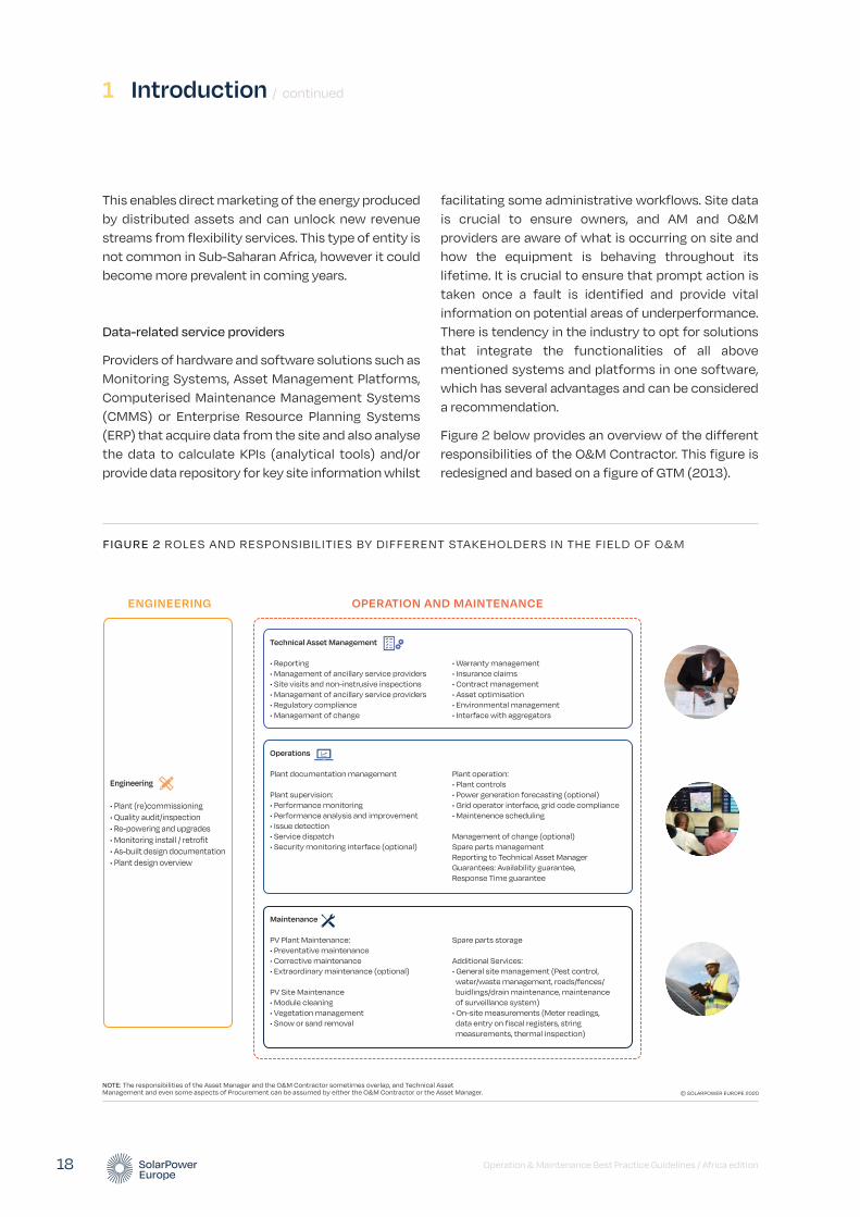
Figure 2 below provides an overview of the different responsibilities of the O&M Contractor. This figure is redesigned and based on a figure of GTM (2013).
1 Introduction / continued
Operation & Maintenance Best Practice Guidelines / Africa edition 18
FIGURE 2 ROLES AND RESPONSIBILITIES BY DIFFERENT STAKEHOLDERS IN THE FIELD OF O&M
© SOLARPOWER EUROPE 2020NOTE: The responsibilities of the Asset Manager and the O&M Contractor sometimes overlap, and Technical Asset Management and even some aspects of Procurement can be assumed by either the O&M Contractor or the Asset Manager.
OPERATION AND MAINTENANCEENGINEERING
Engineering
• Plant (re)commissioning• Quality audit/inspection• Re-powering and upgrades• Monitoring install / retrofit• As-built design documentation• Plant design overview
Operations
Plant documentation management
Plant supervision: • Performance monitoring• Performance analysis and improvement• Issue detection• Service dispatch• Security monitoring interface (optional)
Plant operation: • Plant controls• Power generation forecasting (optional) • Grid operator interface, grid code compliance• Maintenence scheduling
Management of change (optional)Spare parts managementReporting to Technical Asset ManagerGuarantees: Availability guarantee, Response Time guarantee
Maintenance
PV Plant Maintenance: • Preventative maintenance• Corrective maintenance• Extraordinary maintenance (optional)
PV Site Maintenance• Module cleaning• Vegetation management• Snow or sand removal
Spare parts storage
Additional Services:• General site management (Pest control, water/waste management, roads/fences/ buidlings/drain maintenance, maintenance of surveillance system)• On-site measurements (Meter readings, data entry on fiscal registers, string measurements, thermal inspection)
Technical Asset Management
• Reporting• Management of ancillary service providers• Site visits and non-instrusive inspections• Management of ancillary service providers• Regulatory compliance• Management of change
• Warranty management• Insurance claims• Contract management• Asset optimisation• Environmental management• Interface with aggregators
The large number of responsibilities and interdependencies may result in “grey zones” meaning areas of responsibilities where assignments or tasks are not reasonably well allocated or delimitated between one stakeholder’s responsibilities over another’s. This can be the case mainly in the case of larger systems, where the different roles are assumed by different entities. With this perspective, it is important that contracts define as precisely as possible scope, rights and obligations of each party and the general work order management. In this spirit, in case of doubt whether a necessary task is covered or not appropriate and timely communications with the asset owner is of utmost importance to avoid unnecessary yield losses and possible incipient stages of future accusations or even litigations.
Therefore, all stakeholders are encouraged to have a good understanding of both technical and financial aspects of a PV power plant operation in order to ensure a successful and impactful implementation of services for all parties involved. This train of thought requires Asset Managers to have technical skills in-house or to hire an independent technical advisor (engineer) for a meaningful supervision and proper assessment of the technical solutions, and O&M contractors to have the ability to cost-assess and prioritise their operational decisions and maintenance services.
1.4. Costs and benefits of best practices
Best practices describe a method or technique that is generally accepted as superior to any other alternative method or technique to attain a certain result. Therefore, best practices may exceed the minimum requirements expressed in standards. The benefit of adopting best
practices by consistent application typically result in lower cost over the entire cycle, even though the initial cost to implement best practices may come along at a premium. In particular, adhering to best practices is (1) an effective element in risk management and (2) can result in significant yield optimizations.
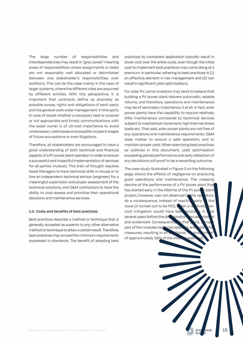
For solar PV, some investors may tend to believe that building a PV power plant delivers automatic, reliable returns, and therefore, operations and maintenance may be of secondary importance, it at all. In fact, solar power plants have the capability to require relatively little maintenance compared to technical devices subject to mechanical movement, high thermal stress loads etc. That said, solar power plants are not free of any operations and maintenance requirements. O&M does matter to ensure a safe operation, and to maintain proper yield. When exercising best practices as outlined in this document, yield optimisation exceeding planed performance and early detection of any deviations will proof to be a rewarding outcome.
The case study illustrated in Figure 3 on the following page, shows the effects of negligence on practicing good operations and maintenance. The creeping decline of the performance of a PV power plant that has started early in the lifetime of the PV power plant project, however, was not observed by the operators. As a consequence, instead of reacting early to the issue (it turned out to be PID), when a relatively low-cost mitigation would have been possible, it took several years before the deterioration was ascertained and evidenced. Consequently, at that point, a major part of the modules had to be replaced, amongst other measures, resulting in an additional “re-investment” of approximately 38% of the initial investment.
Operation & Maintenance Best Practice Guidelines / Africa edition 19

1 Introduction / continued
Operation & Maintenance Best Practice Guidelines / Africa edition 20
FIGURE 3 CASE STUDY OF A YIELD REVIEW OF A CHALLENGED PV POWER PLANT PROJECT
© SOLARPOWER EUROPE 2020SOURCE: EXXERGY.
Cum
ulat
ive
cash
flow
Investmentphase
Exploitation phase
Cumilative cash flow plan vs. actual
Time 6 years
Initial deviation
Initial reaction
Corrective measures
Plan
Actual
Permanent cash flow gap
Cash infusion ∼38% of initial investment = ∼4 years setback
Operation & Maintenance Best Practice Guidelines / Africa edition 21
Definitions
2
This section introduces a basic set of definitions of important terms that are widely used in the O&M field (contracts) and is necessary for all different stakeholders to have a common understanding. In general, there are standards in place that explain some of these terms, however, it is still difficult in practice to agree on the boundaries of those terms and what exactly is expected under these terms or services (e.g. the different types of maintenances or operational tasks).
Indeed, it is more challenging for terms in the Operational field since those are less technical and not standardised as in the case for Maintenance. The chapter provides a short list (alphabetically ordered) which is not exhaustive but reflects the different sections of this document. For the definitions relating to Maintenance the standard EN 13306 (“Maintenance terminology”) was used as a basis.∼
© REAZ
Additional services Actions and/or works performed, managed or overseen by the O&M Contractor, which are not (but can be if agreed) part of the regular services and normally charged “as-you-go”, e.g. ground maintenance, module cleaning, security services etc. Some of the additional services can be found as a part of the Preventive Maintenance, depending on the contractual agreement.
Asset management Asset Managers are responsible for the commercial and financial management of a solar investment and the supervision and control of technical activities. They manage a company or a portfolio rather than a power plant, often across different geographies, dealing with a variety of regulatory frameworks and business models. Asset management is also defined as the coordinated activities of an organisation to generate value from its assets (ISO 55000).
Asset management platform
A software package or suite of tools that is used by the Asset Manager to store and manage technical and non-technical data and information collected from and relating to the solar asset, portfolio or SPV. It combines the abilities of a Computerised Maintenance Management System (CMMS) and an Enterprise Resource Planning System (ERP).
Computerised Maintenance Management System (CMMS)
A software designed to measure and record various O&M KPIs (e.g. Acknowledgement Time, Intervention Time, Reaction Time, Resolution Time) and equipment performance (e.g. Mean Time Between Failures) and thus optimise maintenance activities.
Contract management Activities related to the proper fulfilment of O&M contract obligations such as reporting, billing, contract amendments, regulator interaction etc.
2 Definitions / continued
Operation & Maintenance Best Practice Guidelines / Africa edition 22
Commercial Operation Date (COD)
The term “COD” means “Commercial Operation Date” and is referred to as the day that the PV power plant becomes fully operational and can begin selling power under the terms of the PPA, a FIT, or a merchant business model.
Commissioning System commissioning closes the construction phase of the solar power plant to move towards the commercial operation. Commissioning includes performance and reliability tests to make sure that the solar power plant is built according to the international standards and best industry practice complies with the agreed Employer’s Owner’s Requirements, grid specifications.
Construction In the Construction phase, the solar power plant is installed based on installation manuals provided by suppliers. Construction works involve civil works (mounting structure) and electro-mechanical works (modules, inverters etc) and supervisory and monitoring equipment. Some parts of the construction may be subcontracted by the EPC provider.
Contractual framework An agreement with specific terms between the Asset Owner and the O&M Contractor. This agreement defines in detail the O&M services, both remote operations services and local maintenance activities, the management and interfaces of those services, as well as the responsibilities of each party. Liquidated damages and bonus schemes are also part of the contractual commitments.
Control Room Services (also known as Operations Centre Services or Remote Operations Centre)
Comprehensive actions like PV plant monitoring, performance analysis, supervision, remote controls, management of maintenance activities, interaction with grid operators, authorities, Asset Owners, and the preparation and provision of regular reporting performed by experienced and qualified staff in a control room during operational hours for 365 days/year.
Corrective maintenance Actions and/or techniques (immediate or deferred) taken to correct failures, breakdowns, malfunctions, anomalies or damages detected during inspections, or through monitoring, alarming, or reporting or any other source. The actions are desired to restore the PV system back into regular and required operation mode.
Data and monitoring requirements
Hardware and software, technical and functional specifications to collect, transmit and store production, performance and environmental data for plant management.
Development (Project development)
Development is the phase that precedes the EPC phase in the lifecycle of the project. It usually includes the initiation of the project, site selection, customer identification, conducting preliminary studies, application for permits, securing the financing and selection of the EPC contractor. Project developers may own the project in the early development stages or even longer. The term “Project development” is sometimes considered to include some parts of Engineering and Procurement..
Distributed solar generation
Distributed solar generation refers to solar installations which are small-scale (usually below 1 MWp nominal power). An important characteristic of distributed solar generation is that the generation unit is usually located close to the consumption point, as opposed to the case of conventional and centralised power generation. Distributed solar installations may be equipped with battery storage, and may be connected to the utility grid or be part of a microgrid, or be standalone off-grid systems.
Documentation management system
A management system that records, manages and stores documents required for O&M, such as technical plant and equipment documentation and drawings, maintenance manuals, photos and reports, including the various versions that are being created by different users, reviews and approvals. Documentation management system also defines a proper format and use (information exchange).
Operation & Maintenance Best Practice Guidelines / Africa edition 23
Engineering The Engineering phase starts off as a basic technical concept, the engineering design is itself a process that evolves and is constantly refined as the project development advances into a detailed execution design blueprint, issued for construction. Once construction and commissioning are completed, a detailed set of “as built” set of documents is handed over to the O&M provider.
Environment, Health & Safety (EH&S)
Environment, Health and Safety indicates the activities performed to ensure environmental protection, occupational health and safety at work and on site, applicable to staff and visitors according to the national applicable laws and regulations.
Engineering, Procurement, and Construction (EPC)
EPC refers to companies that deal with the Engineering, Procurement, Construction and Commissioning of solar systems. The EPC contractor is in charge of delivering the fully built solar power plant to the Asset Owner from authorisation to commissioning and grid connection.
Enterprise Resource Planning System (ERP)
A business management software that a company (such as an O&M contractor or an asset manager) can use to gather, store, manage and analyse all types of data relevant for their operations.
Extraordinary maintenance
Actions and/or works performed in case of major unpredictable faults, such as serial defects, force majeure events etc, that are generally considered outside of the ordinary course of business.
Feed-in tariff (FiT) A policy mechanism (designed to accelerate investment in renewable energy technologies) which remunerates, through a long term contract, a fixed electricity prices to renewable energy producers for each unit of energy produced and injected into the electricity grid.
Good industry practice Good Industry Practice means those practices, methods, techniques, standards, codes, specifications, acts, skills and equipment generally applicable in the international solar power industry (including construction and installation of solar power facilities) and followed or used by good contractors that, in the exercise of prudent, proper and good judgment, in light of the facts known or that reasonably should have been known at the time a decision was made or an action taken or omitted, would have been expected to accomplish the desired result in a manner consistent with applicable laws and permits, are reliable and safe, protect the environment, are economically efficient and are done with the degree of skill, diligence and prudence that would ordinarily be expected.
Grid code compliance requirements
Equipment, procedures, actions and activities required by the respective grid operator(s) in order to comply with grid safety, power quality and operating specifications.
Insurance claims Customer’s activities required to claim a reimbursement based on specific insurance policy terms.
Key Performance Indicator (KPI)
A technical parameter that helps the stakeholders to evaluate the successful operation of a PV plant and/or the success of the O&M Contractor’s activities.
Management of change Management of change defines the way to handle necessary adjustments of the design of a PV power plant after the Commercial Operation Date. Changes require a close cooperation between the plant owner and the O&M Contractor.
2 Definitions / continued
Operation & Maintenance Best Practice Guidelines / Africa edition 24
Monitoring system The digital platform used for the overall monitoring of the functioning, energy generation and reference data of the PV plant and its components or PV plant portfolio), which is performed through real-time monitoring software. The monitoring operates 24 hours a day, all year, and is fed by in-plant data logging systems that collect data from different plants as well as by irradiation and temperature measurements from particular sensors and other sources such as meteorological information.
Off-grid solar An off-grid solar installation is a solar installation which is not connected to the utility grid, as opposed to an on-grid or grid-connected installation. An off-grid system may be part of a microgrid or a standalone system such as a solar home system with battery storage.
Performance analysis & improvement
Measurements, calculations, trending, comparisons, inspections etc performed in order to evaluate the PV plant, segments and/or single component performance, site conditions, equipment behaviour etc, and to provide reports and assessment studies to interested parties (customer, public authority, etc).
Personnel & training Operators, technicians, engineers and managers employed for the execution of the O&M activities and training plans/programmes to train them on relevant PV plant related aspects and to keep them continuously updated on their respective roles.
Power plant controls Actions required by the grid operator, for controlling active and/or reactive power being fed into the grid, other power quality factors that are subject to adjustments and/or (emergency) shut down (if applicable).
Power plant supervision The activity to supervise and analyse data provided by the monitoring system which is performed by experienced human resources during daylight hours and managed by one or more control rooms (365 days/year). The reception and qualification of the alarms from the monitoring tool is also considered to be part of the supervision.
Predictive maintenance Actions and/or techniques that are performed to help assess the condition of a PV system and its components, predict/forecast and recommend when maintenance actions should be performed. The prediction is derived from the analysis and evaluation of significant parameters of the component (e.g. parameters related to degradation). Monitoring systems and expert knowledge are used to identify the appropriate actions based on a cost benefit analysis.
Preventive maintenance Actions and/or testing and/or measurements to ensure optimal operating conditions of equipment and of the entire PV plant and to prevent defects and failures. Those take place periodically and according to a specific maintenance-plan and maintenance schedules.
Power generation forecasting
Adoption of forecasting tools calculating expected power production for a certain timeframe from weather forecasts in order to supply the expected power production to owner, grid operator, energy traders or others. This is normally country and plant dependent.
Quality Quality is a perceptual, conditional, and somewhat subjective attribute and may be understood differently by different people. It is a commitment to customers in the market. It can also be defined as fitness for intended use. Quality also takes into account the reduction of waste that a product may cause to the environment or human society.
Quality Management (QM)
Quality Management is the process through which an organisation ensures Quality. Its four pillars are Quality Control & Assurance, Quality Monitoring & Review, Quality Improvement and Quality Planning.
Operation & Maintenance Best Practice Guidelines / Africa edition 25
Regulatory compliance Compliance to any law, statute, directive, bylaw, regulation, rule, order, delegated legislation or subordinate legislation directly applicable in the country where the service is provided, as well as to any mandatory guidelines and measures issued by a utility and any other competent public authority.
Reporting and other deliverables
Deliverables produced periodically, according to requirements detailed in the O&M agreement or following best market practices, including PV plant performance, Key Performance Indicators, maintenance activities and work orders performed, alarm handling, equipment status, warranty handling activities and spare parts tracking and any other analysis performed in compliance with the O&M contract requirements.
Risk Risk is defined as the “effect of uncertainty on objectives”. The major categories of PV risk include, but are not limited to, financial risks, country and regulatory risks, contractual risks, commercial risks, technical risks and reputational risk.
Risk management The practice of identifying and analysing the risks to which solar power systems and operations are subjected and taking steps to mitigate them. The different risk management methods are risk avoidance, risk reduction, risk control, risk transfer. The risk that cannot be mitigated is called residual risk.
Special Purpose Vehicle (SPV)
A company with its own rights, assets and liabilities, created for building, owning and operating one or more solar power plants. The SPV is also referred to as SPE (special purpose entity) or as a project company. SPVs are usually used for larger, utility-scale projects.
Security Actions, procedures, equipment and/or techniques that are adopted on site and remotely in order to protect the plant from theft, vandalism, fire and unauthorised entry. Security services are to be provided be specialised security service providers.
Spare parts management Activities that ensure availability of the right amount and type of components, equipment, parts etc, either on site or in warehouses or in manufacturers’ consignment stocks, for prompt replacement in case of failure and/or to meet guarantees under O&M contracts.
Supervisory Control and Data Acquisition (SCADA)
Supervisory Control and Data Acquisition (SCADA) is a data acquisition system that connects various hardware and software components in a given site and is used to monitor and control the solar power plant remotely. SCADA systems are typically employed to send data to a centralised Monitoring System for monitoring and analytical purposes (see definition for “Monitoring System”).

Operation & Maintenance Best Practice Guidelines / Africa edition 26
The Asset Owner has the ultimate legal and moral responsibility to ensure the health and safety of people in and around the solar plant and for the protection of the environment around it. The practical implementation is normally subcontracted to the O&M Contractor.
3.1. Environment and social
Renewable energies are popular because of their low environmental impact and it is important that solar plants are operated and maintained to minimise any adverse effects. Environmental problems can normally be avoided through proper plant design and maintenance – for example, bunds and regular inspection of HV transformers will reduce the chances of significant oil leaks – but where issues do occur the O&M Contractor must detect them and respond promptly. Beyond the environmental damage there may be financial or legal penalties for the owner of the plant.
Legal obligations to be fulfilled by the O&M Contractor (or the Technical Asset Manager) may include long-term environmental requirements to be implemented either onsite or off-site. Typical requirements can be amongst others water tank installation, tree clearing, drainage systems installation, amphibian follow-up, edge plantation, reptile rock shelters installation. Such requirements should be implemented and managed by the O&M Contractor in order to comply with the authorisation. As a best practice, the O&M Contractor’s environmental preservation activities can go beyond legal obligations.
Further the use of water needs to be considered. Water is used in many installations of solar plants in Africa.
Primarily the water is used for cleaning of the solar modules, further water is used in sanitary installations of the solar plants. The amount of water required depends mostly upon the cleaning requirements of the solar modules. It is estimated that the yearly amount of water needed is at least 100 t/MWp for a solar plant where the solar modules are regularly cleaned during the dry season. In many instances the water is taken from nearby sources through contractors that also conduct the cleaning of the solar modules. The contactors for cleaning the solar modules are often local farmers that conduct the cleaning of the solar modules to complement their income.
The water demand from a solar plant can play a significant role in the water balance of a region. This is of particular importance when considering that water scarcity and dwindling groundwater resources are a wide-spread and increasingly alarming phenomenon. In many incidences, the operators of the solar plant or their sub-contractors are in a stronger position to source the scarce water and therefore they may endanger the livelihoods of the local population. This situation is to be avoided by all means. Solar plants are typically installed in regions that have abundant sunshine and consequently are rather arid. Thus, the probability for a conflict over water particularly for solar plants is rather high and it will increase with the expected fast expansion of installed solar capacity.
In order to avoid a conflict over water the question of the water requirement from the solar plant as well as the local availability of water also in stressed situations is to be analysed as part of the Environmental Social Impact Assessment (ESIA) prior to implementing the project (best practice for C&I projects,
Environment, Health & Safety
3© Thanit Pkc / Shutterstock

recommendation for small-scale projects). An outcome of the ESIA might be on the one hand potential optimisation of the design of the solar plant. On the other hand, any measures required to minimize or mitigate impacts and risks, such as water conflicts, are determined and to be documented in an Environmental, Social Management Plan (ESMP) which is monitored during the construction and the operation of the solar plant.
So far in cases where a potential conflict over water has been determined to be an important risk a rainwater harvesting system has been identified as a possible remedy. In practice these rainwater harvesting systems have shown to be rather simple to install and effective in saving water. Further dry-cleaning - in particular robotic dry-cleaning - has been tried in various installations and has also shown to be very effective. Both rainwater harvesting and robotic
Operation & Maintenance Best Practice Guidelines / Africa edition 27
BOX 1 Preserving and enhancing the Natural Capital values of large-scale solar plants
The growth in ground-mounted solar parks is occurring at a time when there is increasing recognition of the benefits the natural environment provides to society, and how these are under threat from ongoing environmental degradation. When well-managed and in suitable locations, solar parks offer an opportunity to improve the state of the natural environment alongside their primary purpose of generating electricity. This potential is becoming increasingly pertinent with the development of initiatives that prioritise the environment, such as the European Union-funded project Natural Capital Accounting and Valuation of Ecosystem Services (NCAVES), which is active five countries worldwide including South Africa, and global frameworks such as the Paris Agreement and related Sustainable Development Goals. Further, promoting good environmental stewardship will enhance the solar industry’s profile, contribute to corporate Environmental, Social and Governance (ESG) objectives, help to meet planning policy goals, and improve community and landowner relations.
‘Ecosystem Services’ and ‘Natural Capital’ are two related frameworks that are being used to characterise and quantify the benefits that the environment provides for us. Natural Capital is the stocks of environmental assets (e.g. water, air, soil, and living material), from which ecosystem goods (e.g. crops and drinking water) and ecosystem services (e.g. climate regulation and pollination) that society rely on are derived.
Solar parks offer an excellent and relatively untapped opportunity to enhance natural capital and ecosystem services as they occupy a notable amount of land for
25-40 years, which is predominantly used solely to produce low carbon energy. The land remains relatively undisturbed, apart from by maintenance activities. Moreover, because the parks are commonly located in agricultural landscapes, the land they occupy and its immediate surroundings stand to benefit significantly from enhancement. For example, introducing pollinator habitats on solar parks could improve pollination of surrounding crops leading to higher yields, and changes to the intensity of mowing and grazing can be used to enhance biodiversity.
In the United Kingdom, collaborative research between solar park stakeholders, nature conservation bodies and researchers has produced the Solar Park Impacts on Ecosystem Services (SPIES) decision support tool. The SPIES tool provides an accessible, transparent and evidence-based means of informing management actions on and around solar parks. It is free to use and enables users to explore the impacts of different management scenarios, which can be outputted as PDF documents suitable to support planning applications.
Whilst currently deployed in a UK context, alternative versions of SPIES could be readily developed for other ecosystems. By engaging more actively in the natural capital and ecosystem services agendas, the solar industry would boost its environmental credentials, enabling it to continue to produce urgently needed low-carbon electricity while also improving the state of the natural environment upon which society relies.
The SPIES tool is a collaboration between Lancaster University and the University of York funded by the Natural Environment Research Council (NE/N016955/1 & NE/R009449/1). The web-based version of the SPIES tool was developed by Simomics Ltd. 2
1 For more information, see: www.lancaster.ac.uk/SPIES and www.energyenvironment.co.uk.
3 Environment, health & safety / continued
Operation & Maintenance Best Practice Guidelines / Africa edition 28
through proper hazard identification, careful planning of works, briefing of procedures to be followed, and regular and well-documented inspection and maintenance (see also 6.10. Power plant security).
The dangers of electricity are well known and can be effectively managed through properly controlled access and supervision by the O&M Contractor. Any person accessing a PV plant should expect some form of introduction to ensure they are briefed on any hazards and risks. Staff working on electrical equipment must be appropriately trained, experienced and supervised, but it is also key that others working around the equipment - for example panel cleaners - are equally aware of the potential risks and have safe methods of working around HV and LV electricity.
Hazardous areas and equipment should carry appropriate markings to warn personnel of possible hazards and wiring sequence. Such markings should be clear and evident to all personnel and third parties (and intruders) entering the plant premises.
As well as the inherent dangers of a typical solar plant, every site will have its own set of individual hazards which must be considered when working on the plant. An up-to-date plan of hazards is important for the O&M Contractor to use to manage his own staff and to provide third party contractors with adequate information. It is usually the case that the O&M Contractor holds the authority and responsibility to review and, where necessary, reject works taking place in the plant. Failure to carry this out properly has important consequences to general safety.
Besides workers on the solar plant, it is not unusual for other parties to require access to it. This may be the Asset Owner, or their representative, the landlord of the land, or in some situations members of the public. It is important that the plant access control and security system keeps people away from areas of danger and that they are appropriately supervised and inducted as necessary.
The Asset Owner is ultimately responsible for the compliance of H&S regulations within the site/plant. The Asset Owner must make sure that, at all times, the installation and all equipment meet the relevant legislations of the country and also, that all contractors, workers and visitors respect the H&S Legislation by strictly following the established
dry-cleaning approaches however require to be planned before installation of the solar plant in order to allow for reasonable cost.
During O&M all aspects determined in the ESMP concerning the use of water are to be monitored. In case no ESMP has been developed prior to the installation of the solar plant, then the question of water use and potential conflict over water is to be analysed by a suitable expert and the measures determined through this analysis are to be implemented.
Other aspects that need to be taken into account, as best practice, are recycling of broken panels and electric waste so that glass, aluminium and semiconductor materials can be recovered and reused and hazardous materials disposed of in a safe manner complying with legal requirements. In areas with water scarcity, water use for module cleaning should be minimised.
In many situations, solar plants offer an opportunity, where managed sympathetically, to provide opportunities for agriculture and a valuable natural habitat for plants and animals alongside the primary purpose of generation of electricity. A well thought out environmental management plan can help promote the development of natural habitat, as well as reduce the overall maintenance costs of managing the grounds of the plant. It can also ensure the satisfaction of any legal requirements to protect or maintain the habitat of the site. In any case, environmental requirements from building permits should be complied with. Maintenance services should comply with things such as the proper application of herbicides, pesticides, and poisons used to control rodents. The use of solvents and heat-transfer fluids also need to be controlled. Cleaning agents (soap) should be specified to be environmentally friendly (no chlorine bleach) and applied sparingly to avoid over-spray and run-off.
3.2. Health and safety
Managing the risks posed by the solar plant to the health and safety of people, both in and around the plant, is a primary concern of all stakeholders. Solar plants are electricity generating power stations and pose significant hazards present which can result in permanent injury or death. Risks can be mitigated
Operation & Maintenance Best Practice Guidelines / Africa edition 29
procedures, including the use of established personal protective equipment (PPE).
At the same time, the O&M Contractor should prepare and operate its own safety management systems to be agreed with the Asset Owner taking into account site rules and the Works in relation to health and safety and perceived hazards. The O&M Contractor should ensure that it complies, and that all subcontractors comply with the H&S legislation.
The Asset Owner will have to require from the O&M Contractor to represent, warrant and undertake to the Owner that it has the competence and that it will allocate adequate resources to perform the duties of the principal contractor pursuant to specific national regulations for health and safety.
Before starting any activity on-site the Asset Owner will deliver risk assessment and method statements to the O&M Contractor who will provide a complete list of personnel Training Certifications and appoint a H&S coordinator. During the whole duration of the contract the O&M Contractor will keep the H&S file of each site updated.
The O&M Contractor must have their personnel trained in full accordance with respective national legal and professional requirements that generally result in specific certification to be obtained, for example in order to be allowed to work in MV and/or HV electrical plants. Examples of standards used today are ISO 14001, OHSAS 18001, etc). Site certification should be dated and renewed every 1 or 2 years.
In order to achieve a safe working environment, all work must be planned in advance. Normally written plans are required.
Risk assessments need to be produced, which detail all of the hazards present and the steps to be taken to mitigate them.
The following dangers are likely to exist on most solar plants and must be considered when listing hazards in order to identify risks. The severity of any injuries caused is commonly exacerbated by the terrain and remoteness common on solar plants.
1. Medical problems. It is critical that all personnel engaged in work on solar farms have considered and communicated any pre-existing medical conditions and any additional measures that may be required to deal with them.
2. Slips, trips and falls. The terrain, obstacles and equipment installed on a solar farm provide plenty of opportunities for slips, trips and falls both at ground level and whilst on structures or ladders; and for carport systems, fall-protection and additional equipment is required when working at heights. For large roof-top systems, additional fall protection equipment or systems such as cat ladders, lifelines or walkways are recommended.
3. Collisions. Collisions can occur between personnel, machinery/vehicles and structures. The large areas covered by solar farms often necessitate the use of vehicles and machinery, which when combined with the generally quiet nature of an operational solar farm can lead to a lack of attention. General risks such as difficult terrain, reversing without a banksman and walking into the structure supporting the solar panels require special attention. All permanent workers should be insured.
4. Strains and sprains. Lifting heavy equipment, often in awkward spaces or from uneven ground, presents increased risk of simple strains or longer term skeletal injuries.
5. Electrocution. Operational solar farms, whether energised or not, present a significant risk of electrocution to personnel. This risk is exacerbated by the nature and voltage of the electricity on site and the impossibility of total isolation. Staff engaged in electrical work obviously suffer the greatest risk but everybody on site is at risk from step potential and other forms of electrocution in the event of a fault. Specific training needs to be given to all those entering a solar farm as to how to safely deal with the effects of electrocution. In addition to general electrical safety, common issues for PV plants include: arc-flash protection when working on energized circuits; and lock-out-tag-out to ensure circuits are not unintentionally energised.
6. Fire. Several sources of combustion exist on a solar farm, the most common being electrical fire.. Others include combustible materials, flammable liquids, and grass fires. Safe exit routes need to be identified and procedures fully communicated. All personnel need to be fully aware of what to do to both avoid the risk of fire and what to do in the event of a fire.
7. Mud and water. Many solar farms have water travelling through them such as streams and rivers, some have standing water, and some are floating arrays. Mud is a very common risk particularly in winter as low-grade farmland is often used for solar farms. Mud and water present problems for access as well as electrical danger.
8. Mechanical injury. Hand-tools, power tools, machinery as well as such mechanisms as unsecured doors can present a risk of mechanical injury on site.
9. Weather. The weather presents a variety of hazards, the most significant of which is the risk of lightning strike during an electrical storm (relatively high frequency of lightning events in Africa). Due to the metal structures installed on a solar farm an electrical storm is more likely to strike the solar array than surrounding countryside. A solar farm MUST be vacated for the duration of any electrical storm. Working in cold and rainy weather can cause fatigue and injury just as working in hot sunny weather presents the risk of dehydration, sunburn, and sun stroke. Working during sunny days to perform maintenance and/or testing can lead to sunstroke. To avoid this, drinking sufficient water and staying in the shade is recommended.
10. Wildlife and livestock. The renewable energy industry is proud to provide habitats for wildlife and livestock alongside the generation of electricity. Some wildlife however presents dangers. There are plants in different regions which can present significant risk, some only when cut during vegetation management. Animals such as rodents, snakes, insects such as wasps and other wildlife as well as livestock can present significant risks. The nature of these risks will vary from place
to place and personnel need to be aware of what to do in the event of bites or stings. Snakes, spiders, ticks, bees and bugs are common and pose a number of hazards where snake bites can be lethal, spider bites can cause pain and inflammation, tics bites can result in tick bite fever, bees can cause allergic reactions and bugs can fly into people’s eyes. It is therefore important that all precautions are taken to prevent or manage these incidents. Storage and application of pesticides, herbicides, and rodent poisons also introduce health and safety hazards. For example, Glyphosate was very common in controlling vegetation at PV plants and has been found to be carcinogenic. Mowing has several hazards including flying objects. Every job at a PV site should have safety precautions identified and implemented.
Everyone entering a solar farm, for whatever reason, should be trained on the dangers present on solar farms and on the individual task that they will be performing. They should have the PPE and tools necessary to carry out the work in the safest way possible. The work should be planned in advance and everyone concerned should have a common understanding of all aspects related to the safe execution of their task. Different countries will mandate written and hard copy paperwork to meet legislation, but best practice is to exceed the minimum requirements and to embrace the spirit of all relevant legislation.
Best practice in H&S sees the ongoing delivery of training and sharing of lessons learned and work methods. By increasing the skills of persons involved in the industry, we can make the industry both safer and more productive.
3 Environment, health & safety / continued
Operation & Maintenance Best Practice Guidelines / Africa edition 30

Operation & Maintenance Best Practice Guidelines / Africa edition 31
Personnel & training
4
It is of critical importance that all O&M personnel have the relevant qualifications to perform the works in a safe, responsible and accountable manner. This can be a challenge in emerging markets and in certain rural areas in Sub-Saharan Africa, as the necessary technical skills to execute quality O&M services are not always available. In order to address the lack of skills, standard trainings can be relied upon. Such trainings are already provided in a number of African countries by public training institutes and international organisations.
not advisable to be rigid in the necessary requirements. The necessary knowledge and experience can be gained through career development and through different engagements.
The solar industry benefits from a wide range of skills and experience. Team members with a range of electrical, mechanical, financial, business and communications skills are required to handle different tasks and all of them strengthen the positive impact of the service provision.
Everyone who enters a solar plant needs to be trained in the dangers present in addition to their individual skills and experience required for the tasks that they normally perform. Awareness of the necessary health and safety regulations is a must.
As the solar industry globally is a growth industry, it follows that skills will need to be taught in order to create a suitable workforce. It is therefore incumbent on all employers in the industry to create a training scheme both internally and externally which creates opportunities for qualifications and development. Worldwide, there is a huge gender disparity in the industry. As best practise, O&M companies should make an effort to improve diversity and inclusion, ensuring there are training, work, and professional development opportunities for all genders. Whilst it is inevitable that some staff will choose to leave, it is unrealistic to imagine that any company can always employ already skilled and qualified staff.
The creation of a training matrix such as shown on the proposed skills matrix in Annex b enables a company to record skills, both formal and informal, to identify gaps and to provide training to fill the gaps.
As the industry grows, there is a rapid rate of technological change as well as emergent best practices, which require a programme of continuous personal development to which both individuals and companies need to be committed.
The matrix goes beyond any educational background and focuses on the skills required by the O&M company in a specific country. Therefore, many of the skills/requirements are adjustable due to different practices and regulations.
© REAZ

Operation & Maintenance Best Practice Guidelines / Africa edition 32
Technical Asset Management (TAM) encompasses support activities to ensure the best operation of a solar power plant or a portfolio, i.e. to maximise energy production, minimise downtime and reduce costs. It comprises the activities presented in this chapter.
As highlighted in the Introduction, in the African context, and especially in the residential and C&I segments, the installer usually assumes multiple roles in addition to installation. This usually includes the activities called “Technical Asset Management”.
In cases where the Technical Asset Manager and the O&M Contractor are separate entities, a close coordination and information sharing between the two entities is indispensable. This involves an integral knowledge about how much a project should be producing for any given time, considering factors such as weather, seasons, or degradation of assets, etc, ensuring long-term energy infrastructure reliability It represents the entire value chain from investors to asset managers and service providers.
5.1. Technical reporting
The Technical Asset Manager is responsible for preparing and providing regular reporting to the Asset Owner and other stakeholders defined in the agreement between the Asset Owner and the Technical Asset Manager.
The frequency of the reporting can be set daily, weekly, monthly, quarterly or annually (with monthly being the most common and considered a best practice), with specifically defined content for each of these reports.
Generating a report for any specific time range in the past can also be possible. Detailed time-series data should also be reported or at least archived in the reporting system in order to improve the correct availability calculations. The spatial resolution of reports should be on the level of each inverter to better detect under-performing sections of the plants managed.
Table 1 includes some proposed quantitative and qualitative indicators which should be in reports as a minimum requirement, a best practice or a recommendation. For more details on the individual indicators, see chapter 11. Key Performance Indicators.
A new trend in the industry is to extend the reporting beyond the pure PV plant indicators and to incorporate reporting on the actual activities. This means that both the Asset Manager and the O&M Contractor can operate with an Asset Management Platform, ERP CMMS (Computerised Maintenance Management Systems) in order to measure various O&M KPIs (e.g. Acknowledgement Time, Intervention Time, Reaction Time, Resolution Time) and equipment performance (e.g. Mean Time Between Failures). The Technical Asset Manager should also report on Spare Parts Management and in particular on spare parts stock levels, spare parts consumption, in particular PV modules on hand, spare parts under repair. With the emergence of Predictive Maintenance, the Technical Asset Manager can also report on the state of each individual equipment. Furthermore, the periodic reporting can include information on the status of the security and surveillance system. In this case, the security service provider is responsible for providing the relevant input to the Technical Asset Manager.
Technical Asset Management
5© shutterstock

On top of the periodical standard reports (monthly, quarterly or yearly) where operations activities are reported by the Technical Asset Manager to the Asset Owner, it is a best practice for the Technical Asset Manager to provide an intermediate operation report when a fault is generating a major loss. A loss due to a fault is considered major when PR and availability are affected by more than a certain threshold throughout the ongoing monitoring (or reporting) period. A best practice is to set this threshold to 1% of Availability or 1% PR within a reporting period of one month. The
report should be sent as soon as the fault is acknowledged or solved and should contain all the relevant details related to the fault together with recommendations for Extraordinary Maintenance when the necessary operations are not included in the maintenance contract.
• Typically, this maintenance report should contain: Relevant activity tracks (alarm timestamp, acknowledge time, comments, intervention time, operations on site description, pictures etc).
Operation & Maintenance Best Practice Guidelines / Africa edition 33
TYPE OF DATA PROPOSED INDICATOR TYPE OF REQUIREMENT
Raw data measurements Irradiation Minimum Requirement
Active Energy Produced Minimum Requirement
Active Energy Consumed Best Practice
PV Power Plant KPIs Reference Yield Recommendation
Specific Yield Recommendation
Performance Ratio Minimum Requirement
Temperature-corrected Performance Ratio Best Practice
Energy Performance Index Best Practice
Uptime Best Practice
Availability Minimum Requirement
Energy-based Availability Recommendation
O&M Contractor KPIs Acknowledgement time Minimum Requirement
Intervention time Minimum Requirement
Response time Minimum Requirement
Resolution time Minimum Requirement
Equipment KPIs Mean Time Between Failures (MTBF) Recommendation
Inverter Specific Energy Losses Recommendation
Inverter Specific Efficiency Recommendation
Module Soiling Losses Recommendation
Environmental KPIs Environmental and Biodiversity KPIs may vary
depending on the geography, the micro-climate and
the conditions of each site
Best Practice
Incident Reporting Main incidents and impact on production Minimum Requirement
Warranty issues Best Practice
HSE issues Best Practice
Spare parts stock levels and status Best Practice
Physical and Cyber Security Issues Minimum Requirement
Preventive Maintenance tasks performed Best Practice
TABLE 1 PROPOSED INDICATORS/VALUES REQUIRED FOR THE REPORTING

Operation & Maintenance Best Practice Guidelines / Africa edition 34
may coincide with visits to be carried out by the Lender’s Technical Advisor.
5.3. Management of ancillary service providers
Technical Asset Managers or the O&M Contractor is responsible for managing providers of ancillary (additional) services related to PV site maintenance such as panel cleaning and vegetation management; general site maintenance such as road management, site security; or on-site measurement such as meter readings and thermal inspections. For more information see section 7.5. Additional services.
This requires managing a process which spans from tendering for those services all the way to assessing the deliverables and reassuring in coordination with the O&M compliance with environmental, health and safety policies.
5.4. Interface with local energy authorities & regulatory compliance
The Technical Asset Manager is responsible for ensuring that the operation of the PV plant is in compliance with the regulations. Several levels of regulation have to be considered:
• •Many countries have a governing law for the operation of energy generating assets or renewable energy and PV plants in particular. This is something the O&M Contractor should be aware of in any case, even if the O&M Contractor and the Technical Asset Manager are separate entities.
• Power Purchase Agreements (PPA) and Interconnection Agreements must also to be known and respected by the Technical Asset Manager.
• Power generation license agreements need to be made available by the Asset Owner to the Technical Asset Manager so that the Technical Asset Manager can ensure compliance with the regulations of these licenses.
• Further to the regulatory compliance Technical Asset Manager will be responsible to ensure corporate compliance especially on the new post-subsidy environment which is dictated by corporate PPAs and stricter contractual obligations by the owner.
• The estimated production losses at the moment of writing the report
• The estimated production losses for the total duration of the period, counting on the estimated resolution time if the issue is not solved yet
• The device model, type and Serial Number when the fault is affecting a device
• The peak power of the strings connected to the device(s)
• The alarm and status log as provided by the device
• The resolution planning and suggestions. Eventual replacement needed
• Spare parts available
• Estimated cost for the extra-ordinary maintenance
When dealing with owners who are not professional solar stakeholders, additional thought must be given to the information provided to them at all stages of project lifecycle.
• Installers (O&M providers) should be clear about the need for ongoing maintenance and make sure this is reflected in any financial analysis provided to customers. Best practice would involve either
• the retailer providing maintenance service themselves (or),
• ensuring a clear and continuous handover to third party O&M.
• Installers (O&M providers) should provide a manual to the owner with contact information and description of operational indicators and procedures they can do, including clear documentation that states the customer as responsible for maintaining original insolation/shade.
5.2. Site visits and non-intrusive inspections
It is recommended as a best practise that Technical Asset Managers undertake a bi-annual site visit in coordination with the O&M provider to perform a non-intrusive visual inspection, address current maintenance issues and plan out in cooperation with the O&M contractor and the ancillary service providers (if different) a maintenance improvement plan. These
5 Technical Asset Management / continued
Operation & Maintenance Best Practice Guidelines / Africa edition 35
5.5. Warranty management
The Technical Asset Manager can act as the Asset Owner’s representative for any warranty claims vis-à-vis the suppliers of PV plant components. The agreement between the Asset Owner and the Technical Asset Manager should specify warranty management responsibilities of the Technical Asset Manager and the Asset Owner and set thresholds under which the Technical Asset Manager can act directly or seek the Asset Owner’s consent. The Technical Asset Manager or the Operations team will then inform the Maintenance team to perform warranty related works on site. Usually, the warranty management scope is limited by Serial Failures (see definition below in this section). Execution of warranty is often separately billable.
Warranty management can be challenging in emerging markets including some African markets due to the limited local representation of component suppliers and logistical difficulties linked to importing replacement components. These aspects are addressed in chapter 9 on Spare Parts Management.
For any warranty claims the formal procedure provided by the warranty provider should be followed. All communications and reports should be archived for compliance and traceability reasons.
Objectives of Warranty Management:
• Improve the efficiency in complaining processes
• Help to reduce the warranty period costs
• Receive and collect all the warranty complaints
• Support the complaint process
• Negotiate with manufacturers more efficient complaint procedures
• Study the behaviour of the installed equipment
• Analyse the costs incurred during the warranty period
Types of warranties on a PV Plant:
• Warranty of Good Execution of Works
• Warranty of Equipment (Product Warranty)
• Performance Warranty
• Specific regulation for the site such as building permits, environmental permits, management plans and regulations can involve certain requirements and the need to cooperate with the local administration. Examples include restrictions to the vegetation management and the disposal of green waste imposed by the environmental administration body, or building permits restricting working time on site or storage of utilities.
• It is the O&M Contractor’s responsibility to ensure grid code compliance and power generation forecasting. See 6.6. Power Generation Forecasting and 6.7. Grid code compliance. It is the responsibility of the Asset Manager to engage the DNO on discussions which will minimise outages and identify measures to safe-guard export capabilities.
• The Technical Asset Manager plays an important role in supporting the cooperation between the aggregator and the grid operator by informing the aggregator about plant production data, unavailable times, transferring network unavailability information from the grid operator, assuming discussions with the grid operator about the attachment to the balancing portfolio of the respective aggregator, and executing plant shutdown requests (in case of negative prices identified in the day-ahead market).
• Other issues requiring formal compliance include reporting of safety plans and incidents, historic/cultural resource protection, noise ordinances that may limit work at night, and any other regulations imposed by an authority having jurisdiction.
As a minimum requirement the agreement between the Technical Asset Manager and the Asset Owner should list all the relevant permits and regulations and specify that the Asset Owner makes relevant documents available to the Technical Asset Manager.
As a best practice, all regulations, permits and stipulations should be managed within the electronic document management system. This allows the Technical Asset Manager to track reporting and maintenance requirements automatically and report back to the Asset Owner or the administration bodies.
Operation & Maintenance Best Practice Guidelines / Africa edition 36
Warranty of good execution of works and equipment warranties
During the warranty period, anomalies can occur in the facility, which the EPC provider is liable for. The anomalies must be resolved according to their nature and classification, in accordance to what is described in the following sections.
The anomalies or malfunctions that might occur within the facility warranty period might be classified in the following way:
• Pending Works, in accordance to the List of Pending Works (or Punch List) agreed with the client during EPC phase.
• Insufficiencies, these being understood as any pathology in the facility resulting from supplies or construction, that although done according to the project execution approved by the client, has proven to be inadequate, unsatisfactory or insufficient.
• Defects, these being understood as any pathology resulting from supplies or construction executed in a different way from the one foreseen and specified in the project execution approved by the client.
• Failure or malfunction of equipment, being understood as any malfunction or pathology found in the equipment of the photovoltaic facility – Modules, Inverters, Power transformers or other equipment.
Anomalies handling
During the Warranty Period, all the Anomaly processing should, as a best practice, be centralised by the Technical Asset Manager/O&M Contractor, who is responsible for the first acknowledgment of the problem and its framework according to its type and is the main point of contact between the internal organisational structure and the client in accordance to the criteria defined below.
Pending works, insufficiencies and defects
In the case of anomalies of the type “Pending Works”, “Insufficiencies” or “Defects”, the Technical Asset Manager must communicate the occurrence to the EPC provider, who shall be responsible to assess the framework of the complaint in the scope of the EPC contract, determining the action to be taken.
Resolution of failures in the case of anomalies of the type “Failures”
The Technical Asset Manager should present the claim to the equipment supplier within 14 days and follow the claims process.
Serial defects (endemic failures)
Serial defects (endemic failures) are product failures at or above the expected failure rates resulting from defects in material, workmanship, manufacturing process and/or design deficiencies attributable to the manufacturer. Serial defects (endemic failures) are limited to product failures attributable to the same root cause.
Performance warranty
EPC Contractors usually provide a 2-year performance warranty period after the Commercial Operation Date (COD). During the warranty period, it is the responsibility of the Technical Asset Manager to monitor, calculate, report and follow-up the values of Performance Ratio and other KPIs guaranteed by the EPC Contractor.
Within this scope, it is the responsibility of the Technical Asset Manager to:
• Manage the interventions done within the scope of the warranty in order to safeguard the performance commitments undertaken under the contract.
• Periodically inform the Asset Owner about the condition of the contracted performance indicators.
Immediately alert the Asset Owner whenever the levels of the indicators have values or tendencies that could indicate a risk of failure.
Warranty enforcement
A warranty may be voided by mishandling or not observing instructions or conditions of the warranty. For example, storing modules improperly onsite, such that the packaging is destroyed by rain, may void a warranty. In another case, partial shading of a thin-film module voids the warranty. Failure to provide adequate ventilation may void an inverter warranty. The manufacturer’s warranty might cover replacement but not labour to remove, ship, and re-
5 Technical Asset Management / continued
Operation & Maintenance Best Practice Guidelines / Africa edition 37
install an underperforming module. A warranty often gives the manufacturer the option to “repair, replace, or supplement,” with “supplement” meaning to provide modules to make up the difference in lost power. For example, if a system has 10,000 modules that are underperforming by 5%, the guarantor could satisfy the performance warranty by providing 500 additional modules to make up for the lost power, rather than replacing the 10,000 modules. However, increasing the plant size by 500 modules to restore guaranteed power might not be possible due to lack of rack space or electrical infrastructure. Also, expanding the system “nameplate” capacity would generally trigger a new interconnect agreement and permitting. Manufacturers also often have the option of paying a cash-value equivalent to the lost capacity of under-performing modules, but as the price of modules declines, this might be less than originally paid for the modules. Given the complications described above, this option is often preferred by system owners unless there is a required level of performance that must be maintained.
5.6. Insurance claims
The agreement between the Technical Asset Manager and the Asset Owner should specify insurance management responsibilities of the Asset Owner and the Technical Asset Manager. The Technical Asset Manager will at least be responsible for the coordination of site visits by an insurance provider’s representative or technical or financial advisors in connection with the information collection and damage qualification, as well as for the drafting of technical notes to support the reimbursement procedure. The coordination of the insurance claim and the liaison with the insurers, brokers and loss adjusters, as well as finding the best insurance providers is usually with the Commercial/Financial Asset Manager (for more information on this, see section 6.13. Suppliers account management of the Asset Management Best Practice Guidelines).
For any insurance claims the formal procedure presented by the insurance provider should be followed. All communications and reports should be archived for compliance and traceability reasons. Timelines for submission of claims and associated information should be adhered to in order to avoid losses due to non-compliance.
Types of insurance related to PV plant operations and maintenance include:
• Property insurance, hazard insurance: coverage commensurate with the value of equipment and other improvements to a property; may also cover against other risks if included or unless excluded.
• Commercial general liability insurance: in a form covering all actions by owner or contractors, written on an occurrence basis, including coverage for products and completed operations, independent contractors, premises and operations, personal injury, broad form property damage, and blanket contractual liability. Liability of a fire started by the PV system has increased required liability coverage levels for PV systems. A liability policy should cover negligence claims, settlements, and legal costs too.
• Inland insurance or marine insurance: insures against loss of equipment in shipping or not on the property premises. Inland insurance is often covered under property insurance policy.
• Workmen's compensation: covers costs for employee accidents.
• Professional liability insurance: insures against errors and omissions often required by board of directors
• Commercial vehicle insurance: insurance for owned and rented vehicles or personal vehicles used on company business
• Warranty insurance: equipment warranty issued by manufacturer but backed up by an insurance company in the event that the manufacturing company goes out of business. Many insurance companies do not offer warranty insurance but rather cover such risk under property insurance.
• Business interruption insurance covers lost revenue due to downtime caused by covered event—this can be important in PPAs where revenue is essential for debt service and O&M expenditures.
• Energy production insurance covers cases when energy production is less than previously specified, which can improve access to debt financing and reduce debt interest rate. (This is not widely available in Sub-Saharan Africa.)

5 Technical Asset Management / continued
Operation & Maintenance Best Practice Guidelines / Africa edition 38
The procedure for making claims described in the insurance policy should be followed to the letter, keeping copies of all submittals and correspondence with the insurance company. The insurance company (claims adjuster) will need to have access to the site provided to them in order to assess damage and to collect the information needed to process the claim.
With all of the above said, insurance solutions seem to provide an additional risk mitigation measure, and the variety of insurance solutions on the market triggers the challenge to understand the details of the terms and conditions subject to which insurance solutions are offered, and the resulting actual cover that the insurance policy provides. Many insurance solutions turn out to have significant exclusion clauses.
5.7. Contract management (operational contracts)
Contract management encompasses both technical and commercial/financial aspects. This document looks at contract management from a TAM point of view. For details on the perspective of the Commercial/Financial Asset Manager, see section 6.12. Contract management (financial contracts) of the Asset Management Best Practice Guidelines.
The Technical Asset Manager is in charge of ensuring compliance with the operational contracts in place, such as contracts related to O&M services, land lease, insurance, site security, communications and in some cases ancillary (additional) services such as panel cleaning and vegetation control or component procurement. (For more information on procurement, please refer to the Asset Management Best Practice Guideline’s chapter 7. Procurement.)
Indeed, the oversight of and coordination with the O&M Contractor is one of the key responsibilities of the Technical Asset Manager. Thus, the Technical Asset Manager is responsible for performance supervision, too: proper oversight of O&M, detecting when systems are underproducing and quickly and accurately diagnosing an under-performing plant.
The Technical Asset Manager oversees various contractual parameters, responsibilities and obligations of the Asset Owner and the contractual partners linked to the respective solar power plant. Contract management responsibilities depend largely
on factors such as geographic location, project size, construction and off-taker arrangements.
As a minimum requirement, the initial step in this process is a comprehensive analysis of the contracts followed by a well-defined Division of Responsibility (DOR) matrix that clearly delineates which entity is responsible for which action on both the short and long term. Upon mutual agreement between the parties, the DOR can serve as the driving and tracking tool for term of life contractual oversight.
As a form of best practice, the Contract Manager’s responsibilities often also extend to functioning as the initial contact for all external questions. This allows the Asset Owner optimal access to all areas of the service provider’s organisation, and adherence to the contractual responsibilities. The Contract Manager also assumes the responsibility for invoicing of the O&M fees to the Asset Owner.
For quality purposes, the Technical Asset Manager should also track their own compliance with the respective contract, either O&M contract or Asset Management contract, and report to the Asset Owner in full transparency.
5.8. Asset optimisation (technical)
Technical Asset Managers also start being responsible for providing data and information analysis on assets they manage as well as to provide asset optimisation solutions. Primarily based on the following key areas:
• Plant performance
• Operation cost reduction
• Technology adaptation and upgrades (e.g. Revamping and repowering)
• Technical People management and training
It is the role of the Technical Asset Manager to initiate and coordinate discussions with both the Owners and the O&M Contractors to future-proof the assets and come up with a financial proposal based on data analysis which can assist the owners in making informed decisions.
Note that asset optimisation has commercial and financial aspects too, such as contract optimisation, presented in the Asset Management Best Practice Guidelines.
Operation & Maintenance Best Practice Guidelines / Africa edition 39
5.9. Environmental management
Depending on local and international environmental regulations, as well as on the Asset Owner’s CSR and Environmental internal policies, the Asset Owner may have incentives to reduce or control negative environmental impacts.
An increasing body of scientific evidence indicates that well-designed and well-managed solar energy can support wildlife habitats and contribute significantly to national biodiversity targets. In fact, solar parks can have several additional advantages over other agricultural landscapes, in that they are secure sites with minimal human and technical disturbance from construction, require little or no use of chemical pesticides, herbicides or fertilizers, and typically incorporate ecological features such as drainage ponds and hedgerows, which can be designed to maximize the value of their habitat.
The approach to managing biodiversity will be different for every solar park, and it is recommended that a site-specific plan be devised in each case.
Therefore, the Asset Manager is obliged to assess the impact or limitations of environmental legislation on the supplier’s existing contracts. Furthermore, the Asset Manager is required to develop an action plan to address existing problems and minimise their impact.
As an example, the Asset Manager must oversee the O&M provider’s operational field work to ensure compliance with local environmental regulation (use of chemicals to control vegetation, use of diesel cutting machines, etc.); the security contract must be adapted, if possible, according to the wild life existing around the photovoltaic plant and the appropriate security equipment, such as loudspeakers, spotlights and fences, must also be adapted.
Long-term environmental requirements can also include water tank installation, tree clearing, installation of drainage systems, amphibian follow-up, edge plantation, and installation of reptile rock shelters. As a best practice, the Technical Asset Manager’s (or the O&M Contractor’s) environmental preservation activities should go beyond legal obligations.
5.10. Health & safety management
The Technical Asset Manager should oversee that the solar asset and the relevant suppliers comply with health & safety (H&S) requirements. If necessary, the
Technical Asset Manager should hire an H&S expert to ensure compliance. For more information, see chapter 3. Environment, Health & Safety.
5.11. Lifetime conformity assessment
Conformity assessment is generally a widely used process used to show that a product, service, process, body, person or system meets specified requirements. The specified, be it international standards, local codes, best practice guidelines, or other relevant references. A conformity assessment report or certificate is issued by a competent, independent third-party body. That report or certificate will state that the referenced requirements are usually expressed as a form of „standard” that is typically prepared and adopted by an overarching member body based system. While a regular certification is based on a pass-fail logic, a rating differentiates different levels of quality and performance to facilitate the risk assessment for investors and banks. There are various conformity assessment systems, such as the IECRE system, which may be used by Technical Asset Managers. A relevance of the rating system is expected to become relevant also for the African continent and to other emerging markets.
5.12. Force majeure (pandemic) management
With the rise of COVID-19 pandemic, Owners and O&M providers have been impacted in ways previously not seen. Reduced demand for energy as a result of lockdowns and reduced productivity has resulted in project curtailments which have been difficult to mitigate. Agreements between off-takers and generators have been common to allow some exports to continue.
The human cost has directly affected plants with reductions in available staff for O&M leading to delayed or deferred activities by smaller teams. For projects without spare parts on site, access to parts has proven challenging and the logistics of acquiring parts has been affected by global shipping delays. It is unclear if there are long-term lessons to be learned from all these items, but the process for O&M is under closer scrutiny than it has been for years.
The Technical Asset Manager’s role in such circumstances is to negotiate the best possible terms with off-takers and authorities, and implement internal measures in order to maintain business operations and revenues.
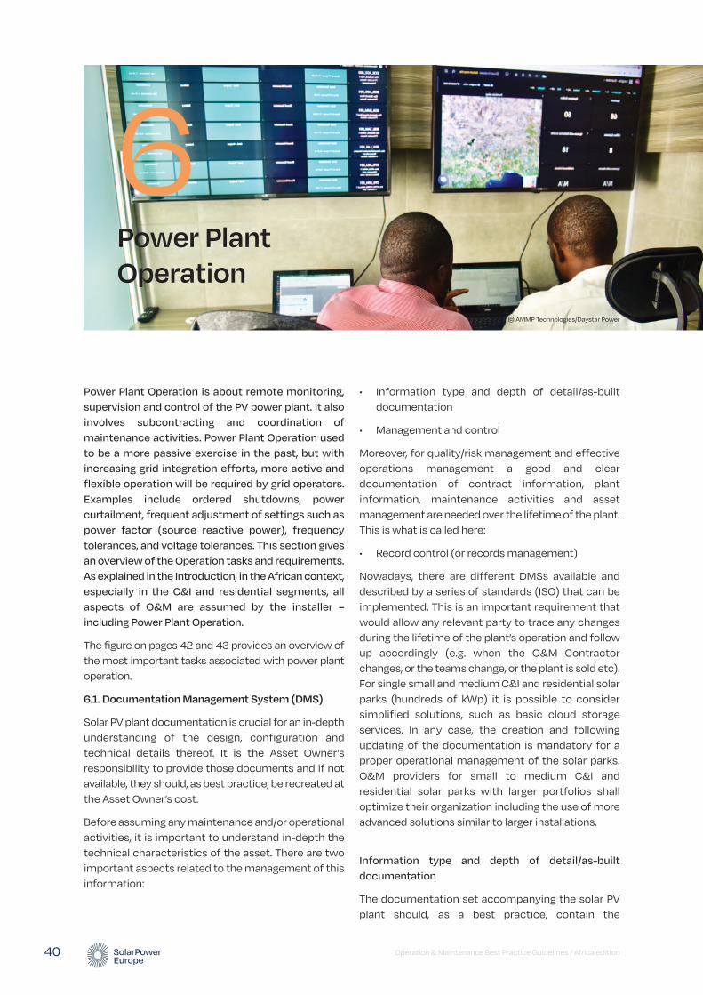
Operation & Maintenance Best Practice Guidelines / Africa edition 40
Power Plant Operation is about remote monitoring, supervision and control of the PV power plant. It also involves subcontracting and coordination of maintenance activities. Power Plant Operation used to be a more passive exercise in the past, but with increasing grid integration efforts, more active and flexible operation will be required by grid operators. Examples include ordered shutdowns, power curtailment, frequent adjustment of settings such as power factor (source reactive power), frequency tolerances, and voltage tolerances. This section gives an overview of the Operation tasks and requirements. As explained in the Introduction, in the African context, especially in the C&I and residential segments, all aspects of O&M are assumed by the installer – including Power Plant Operation.
The figure on pages 42 and 43 provides an overview of the most important tasks associated with power plant operation.
6.1. Documentation Management System (DMS)
Solar PV plant documentation is crucial for an in-depth understanding of the design, configuration and technical details thereof. It is the Asset Owner’s responsibility to provide those documents and if not available, they should, as best practice, be recreated at the Asset Owner’s cost.
Before assuming any maintenance and/or operational activities, it is important to understand in-depth the technical characteristics of the asset. There are two important aspects related to the management of this information:
• Information type and depth of detail/as-built documentation
• Management and control
Moreover, for quality/risk management and effective operations management a good and clear documentation of contract information, plant information, maintenance activities and asset management are needed over the lifetime of the plant. This is what is called here:
• Record control (or records management)
Nowadays, there are different DMSs available and described by a series of standards (ISO) that can be implemented. This is an important requirement that would allow any relevant party to trace any changes during the lifetime of the plant’s operation and follow up accordingly (e.g. when the O&M Contractor changes, or the teams change, or the plant is sold etc). For single small and medium C&I and residential solar parks (hundreds of kWp) it is possible to consider simplified solutions, such as basic cloud storage services. In any case, the creation and following updating of the documentation is mandatory for a proper operational management of the solar parks. O&M providers for small to medium C&I and residential solar parks with larger portfolios shall optimize their organization including the use of more advanced solutions similar to larger installations.
Information type and depth of detail/as-built documentation
The documentation set accompanying the solar PV plant should, as a best practice, contain the
Power Plant Operation
6© AMMP Technologies/Daystar Power
documents described in Annex c. The IEC 62446 standard can also be considered to cover the minimum requirements for as-built documentation.
In general, for optimum service provision and as a best practice, the O&M Contractor should have access to all possible documents (from the EPC phase). The Site Operating Plan is the comprehensive document prepared and provided by the plant EPC, which lays out a complete overview of the plant location, layout, electrical diagrams, components in use and reference to their operating manuals, EH&S rules for the site and certain further topics. All detailed drawings from the EPC need to be handed over to the O&M Contractor and being stored safely for immediate access in case of PV plant issues or questions and clarifications with regards to permits and regulation.
Management and control
Regarding the document control, the following guidelines should be followed:
• Documents should be stored either electronically or physically (depending on permits/regulations) in a location with controlled access. An electronic copy of all documents should be available for all documents.
• Only authorised people should be able to view or modify the documentation. A logbook of all the modifications should be kept. As a best practice, such a logbook should contain minimally the following information:
• Name of person, who modified the document
• Date of modification
• Reason of modification and further information, e.g. link to the work orders and service activities
• Versioning control should be implemented as a best practice. Involved people should be able to review past versions and be able to follow through the whole history of the document.
Record control
A key point is that necessary data and documentation are available for all parties in a shared environment and that alarms and maintenance can be documented in a seamless way. Critical to the
Operations team is that the maintenance tasks are documented back to and linked with the alarms which might have triggered the respective maintenance activity (work order management system log). Photographs from on-site should complement the documentation (when applicable) – photo documentation. Tickets (ticket interventions) should be stored electronically and made available to all partners. The Asset Owner should also maintain ownership of those records for future references.
To learn from the past and ongoing operations and maintenance and to then be able to improve performance via for example Predictive Maintenance in the following years, it is crucial that all data is stored and that all workflows and alarms are stored to create automatic logbooks of operation and maintenance and alarms. Such data collection together with those acquired by the monitoring tool can be used for further analysis and future recommendations to the client. Such analysis and the respective outcomes should also be recorded.
Last but not least, there should be a proper documentation for the curtailment periods as well as the repairing periods when the plant is fully or partly unavailable. This will all be recorded by the monitoring system to be able to measure lost energy during maintenance activities. For this, having the correct reference values at hand is crucial. For important examples of input records that should be included in the record control, see Annex d.
As in the case of the as-built documentation, all records, data and configuration of the monitoring tool and any sort of documentation and log that might be useful for a proper service provision must be backed up and available when required. This is also important when the O&M Contractor changes.
6.2. Plant performance monitoring and supervision
The Operations team is responsible for continuous monitoring and supervision of the PV power plant conditions and its performance. This service is done remotely through the use of monitoring software system and/or plant operations centres. The O&M Contractor should have full access to all data collected from the site in order to perform data analysis and provide direction to the Maintenance service provider/team.
Operation & Maintenance Best Practice Guidelines / Africa edition 41

6 Power Plant Operation / continued
Operation & Maintenance Best Practice Guidelines / Africa edition 42
FIGURE 4 OVERVIEW OF THE MOST IMPORTANT TASKS IN POWER PLANT OPERATION
DOCUMENTATION MANAGEMENT SYSTEM (DMS)
OPTIMISATION OF O&M
PLANT PERFORMANCE MONITORING AND SUPERVISION
PER
GR
POWER PLANT CONTROLS
POWER GENERATION FORECASTING
REPOA
The DMS is an important requirement which allow to trace changes during the lifetime of plant’s operation. The important aspects to trace the PV plant management information are:
To optimize O&M activities, reducing production losses and costs, the following information must be analyzed:
The O&M contractor is responsible for monitoring and supervision of PV plant performance. In the Fault Management there are different role and interaction levels:
The O&M cmonitoringaggregatio
The O&M pin accordaThe requir
The specifon the volt
The Power Plant Controller is a control system that can manage several parameters, such as:
The O&M contractor may provide forecasting services, if required by the Asset Owner. Forecast requirements are characterized by:
The most common KPIs for forecast quality are:
The Operadetails see
• Components and manuals • Plant location overview• PV plant layout • Electrical diagrams• EH&S rules
Information• Response Time correlated to classification of events and root causes• Analysis of costs incurred for various interventions
• Control Room
• Faults detecting • Ticketing • Action coordinating• Site Technician
• Analysis and fault resolution on site
1st level support
Minimum requireme
• Absolute Active Power Control • Power Factor Control • Ramp Control• Frequency Control• Reactive Power Control • Voltage Control
• Forecast horizon (typically below 48 hours) • Time resolution (typically 15 minutes to one hour) • Update frequency: • Day-ahead forecasts • Intraday forecasts • Combined forecasts
• Power qu• Voltage re• Managem• Managem
• Storage of documents • Logbook of modification• Access management
• Alarms linked with maintenance tasks • O&M automatic logbook• Unavailability documentation and recording
Management control
Record control
• PV engineers • Account managers• Project managers
• Vendors’s experts • Project managers• Accounting managers
2nd level support
3rd level support • Root Mean Square Error (RMSE) • Mean Absolute Error (MAE)
Recommen

Operation & Maintenance Best Practice Guidelines / Africa edition 43
PERFORMANCE ANALYSIS AND IMPROVEMENT
GRID CODE COMPLIANCE
MANAGEMENT OF CHANGE
POWER PLANT SECURITY
REPORTING AND TECHNICAL ASSET MANAGEMENT
ion losses analyzed
by the Local
The O&M contractor is responsible for the performance monitoring quality. The data, collected for different time aggregation, should be analyzed at the following level:
The O&M provider is responsible to operate the PV plant in accordance with the respective state grid code. The requirements provided by the grid operator are usually:
The specificities and quality requirements depends on the voltage level of the grid.
In the event that the design of a PV power plant needs to be adjusted, the O&M contractor should be involved from the beginning in the following phases:
Implementation of the plant SCADA and monitoring system is required being able to trace all changes, including:
In order to optimize the activities, the adjustments needs to be applied to the following:
It is necessary that, together with the O&M Contractor, the Asset Owner put in place a Security protocol in case of intrusion on the PV plant. A specialized security service provider will be responsible for:
An intrusion system may be formed by:
Process for liaison with local emergency services, e.g. police should be considered
m that can
rol Room, rovide Owner.
re:
The Local Control Room team is responsible for providingperiodic reporting to the Central Control Room. For moredetails see Chapter 5. Operation Planning.
of events
ntions
• Portfolio level (Central Control Room)• Plant level (Local Control Room)• Inverter level (Local Control Room)
Minimum requirement
hour)
• Power quality • Voltage regulation • Management of active power • Management of reactive power
• Concept • Design works • Execution
• Documentation of inverter replacement date• Inverter manufacturer and type • Inverter serial number
• Site Operating Plan • Annual Maintenance Plan • Annual Maintenance Schedule
• Intrusion systems• Surveillance systems • Processing alarms • Site patrolling
• Simple fencing or barriers • Alarm detection • Alerting system • Remote closed-circuit television (CCTV) video monitoring• Backup communication line (recommended)
• String level (Local Control Room)Recommended
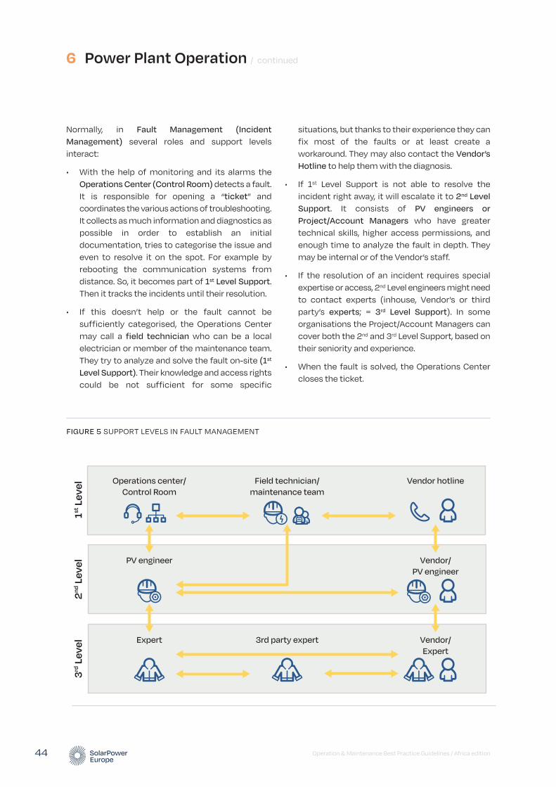
6 Power Plant Operation / continued
Operation & Maintenance Best Practice Guidelines / Africa edition 44
situations, but thanks to their experience they can fix most of the faults or at least create a workaround. They may also contact the Vendor’s Hotline to help them with the diagnosis.
• If 1st Level Support is not able to resolve the incident right away, it will escalate it to 2nd Level Support. It consists of PV engineers or Project/Account Managers who have greater technical skills, higher access permissions, and enough time to analyze the fault in depth. They may be internal or of the Vendor’s staff.
• If the resolution of an incident requires special expertise or access, 2nd Level engineers might need to contact experts (inhouse, Vendor’s or third party’s experts; = 3rd Level Support). In some organisations the Project/Account Managers can cover both the 2nd and 3rd Level Support, based on their seniority and experience.
• When the fault is solved, the Operations Center closes the ticket.
Normally, in Fault Management (Incident Management) several roles and support levels interact:
• With the help of monitoring and its alarms the Operations Center (Control Room) detects a fault. It is responsible for opening a “ticket” and coordinates the various actions of troubleshooting. It collects as much information and diagnostics as possible in order to establish an initial documentation, tries to categorise the issue and even to resolve it on the spot. For example by rebooting the communication systems from distance. So, it becomes part of 1st Level Support. Then it tracks the incidents until their resolution.
• If this doesn’t help or the fault cannot be sufficiently categorised, the Operations Center may call a field technician who can be a local electrician or member of the maintenance team. They try to analyze and solve the fault on-site (1st
Level Support). Their knowledge and access rights could be not sufficient for some specific
FIGURE 5 SUPPORT LEVELS IN FAULT MANAGEMENT
Operations center/
Control Room
PV engineer
Expert
Field technician/
maintenance team
3rd party expert
Vendor hotline
Vendor/
PV engineer
Vendor/
Expert
1st L
evel
2nd L
evel
3rd L
evel
Operation & Maintenance Best Practice Guidelines / Africa edition 45
For small to medium C&I and residential solar parks simplified procedures could be applied to plant performance monitoring and supervision activities. The Fault management could be performed on daily basis introducing a classification of alarms by priority, e.g. with respect to rated power out of service.
Depending on the level of development of the local O&M market, it is also suggested to consider the opportunity to provide during the execution phase a first level maintenance training to local personnel eventually involved in the project. During the operation phase these local resources could be able (at least) to manage the first level troubleshooting and the small repairs with positive impact on reducing the time it takes to intervene and restore solar parks production.
Such kind of approach could also support the development of the local O&M market increasing the quality of the services provided. O&M providers for small to medium C&I and residential solar parks with larger portfolios shall optimise their organisation including cooperation with those local suppliers.
Besides the data from the site, if a CCTV system is available on site, the O&M Contractor should, as a best practice, be able to access it for visual supervision and also have access to local weather information.
The O&M Contractor is responsible for being the main interface between the plant owner, the grid operator and the regulator (if applicable) over the lifetime of the O&M contract regarding production data. The Operations team should be reachable by the Asset Owner via a hotline during daytime, when the system is expected to generate electricity. The Operations team is also responsible to coordinate accordingly with the Maintenance service provider/team.
For more information on monitoring requirements, see Chapter 10. Data and monitoring requirements.
6.3. Performance analysis and improvement
The O&M Contractor makes sure that the performance monitoring is correct.
In general, the data should be analysed down to the following levels:
1. Portfolio level (group of plants) under control of the O&M Contractor (minimum requirement)
2. Plant level (minimum requirement)
3. Inverter level (minimum requirement)
4. String level (as a recommendation)
The analysis should furthermore show the required data on the specific levels listed above and for different time aggregation periods from the actual recording interval up to monthly, quarterly (for medium or large-scale) or semi-annual (for small-scale installations) levels.
The analysis should also include the option for having custom alarms based on client specific thresholds such as for example business plan data or real-time deviations between inverters on-site.
In particular, the agreed KPIs should be computed and reported (see Chapter 11. Key Performance Indicators). Special attention should be paid to the fact that such KPI calculations should take into consideration the contractual parameters between O&M Contractor and Asset Owner , in order to provide an accurate and useful calculation for evaluation and eventually liquidated damages or bonuses.
6.4. Optimisation of O&M
An essential part of Operations is the analysis of all the information generated throughout O&M, such as Response Time, and how this correlates to the various classification of events and root causes. Another vital part of Operations is the analysis of costs incurred for various interventions, categorised into materials and labour. Having such information helps to further optimise the asset by reducing production losses and the cost of O&M itself.
6.5. Power plant controls
It should be noted that this task is usually not applicable for small to medium scale installations. However, if applicable, the Operations team is the responsible contact for the grid operator for plant controls. The Operations team will control the plant remotely (if applicable) or instruct the qualified maintenance personnel to operate breakers/controls on site. The O&M Contractor is responsible for the remote plant controls or emergency shutdown of the plant, if applicable and in accordance with the respective grid operator requirements (see also 6.7.
Grid code compliance) and regulations (see 5.4. Interface with local energy authorities and regulatory compliance). The plant control function varies from country to country and in some cases from region to region. The respective document refers to details in PV plant control regulation which are issued by the respective grid operator and (energy market) regulator.
The Power Plant Controller itself is a control system that can manage several parameters such as active and reactive power and ramp control of PV plants. The set points can normally be commanded either remotely or locally from the SCADA. Moreover, the system should be password protected and log all the executed commands. Any executed commands should release real-time notifications to the Operations team.
The following list shows typically controlled parameters in a PV plant:
• Absolute Active Power Control
• Power Factor Control
• Ramp Control (Active and Reactive Power if needed)
• Frequency Control
• Reactive Power Control
• Voltage Control
6.6. Power Generation Forecasting
Like the previous point, this task is usually not applicable for small to medium scale installations. However, if the Asset Owner requires Power Generation Forecasts, the O&M Contractor may supply such forecasts (usually for large scale plants). Forecasting services for PV power generation are generally offered by operators of PV monitoring services, however external services can also provide this function. The Solar Monitoring Best Practices Mark (www.solarbestpractices.com) is a useful tool to help stakeholders select suitable Monitoring Systems. When the Asset Owner requires Power Generation Forecasting from the O&M Contractor, they could choose a service level agreement with the forecast provider. This kind of activities may have an influence on the contract agreement for electricity dispatching between the Asset Owner and a trading service provider.
The requirements for such forecasts may differ from country to country and also depends on the contract agreement for electricity dispatching between the Asset Owner and a trading service provider. Forecast requirements are characterised by the forecast horizon, the time resolution, and the update frequency, all depending on the purpose. For power system or power market related purposes, forecast horizons are typically below 48 hours and the time resolution is 15 minutes to one hour, in line with the programme time unit of the power system or the market. Common products are day-ahead forecasts, intra-day forecasts and combined forecasts. Day-ahead forecasts are typically delivered in the morning for the next day from 0 to 24 and updated once or twice during that day. Intraday forecasts are delivered and updated several times per day for the rest of the day and should be delivered automatically by the forecast provider.
For long-term planning of unit commitment and maintenance decisions, forecasts with longer time horizons are used, typically one week or more.
PV Power Generation Forecasts rely on numerical weather predictions, satellite data and/or statistical forecasting and filtering methods. Most products combine several of these techniques. Good practice requires numerical weather predictions for day-ahead forecasting and a combination with satellite data for intra-day forecasts. In all cases, good practice requires statistical filtering which in turn requires a near-real-time data feed from the monitoring system to the forecast provider. For best practice, the forecast provider should also be informed about scheduled outages and the expected duration of forced outages.
The most common KPIs for forecast quality are the Root Mean Square Error (RMSE) and the Mean Absolute Error (MAE). They are normalised to peak power and not to energy yield.
6.7. Grid code compliance
The O&M Contractor, and in particular the Operations team is responsible to operate the PV plant in accordance with the respective national grid code. The operator of the grid, to which the PV plant is connected (either low voltage grid or medium voltage grid or high voltage grid) provides the requirements for power quality, voltage regulation and management of
6 Power Plant Operation / continued
Operation & Maintenance Best Practice Guidelines / Africa edition 46
Operation & Maintenance Best Practice Guidelines / Africa edition 47
active and reactive power. The Operations team is responsible to ensure unintentional islanding is avoided in cases of weak grids with frequent load shedding. In some countries (and/or regions) specific grid codes for renewable energy generators and consequently solar PV plants have been issued.
Depending on the voltage level of the grid the plant is connected to, the specificities and quality requirements for the PV plant change. A higher level of the grid usually has more specific and higher quality requirements.
Most of the utility scale PV plants connected to a grid are required to be controllable to meet the grid operator requirements. Such plant controls allow the grid operator to adjust the power output from the PV plant according to the grid capacity and power frequency requirements.
It is expected that the O&M Contractor is familiar with all the details of the grid code and grid operator requirements. Depending on the regulations, either the grid operator himself is steering the PV plant controller (with remote signals) or the Operations team is managing the plant controller per direction of the grid operator.
Similar to some emerging markets around the world, in the African context, a specific challenge facing O&M providers is the fact that many inverters do not have pre-configurations for the local grid code. In such cases the O&M provider should turn to authorities to find the best solution.
6.8. Management of change
In the event that the design of a PV power plant needs to be adjusted after the Commercial Operation Date, the O&M Contractor should, as a best practice, be involved by the Asset Owner and the EPC Contractor and can be a main contributor if not the leader of this change process. Reasons for such changes can be motivated by non-compliance of the PV power plant with the capacity predicted by the EPC, by regulation (introduction of new PV power plant controls regulations), by the unavailability of spare parts or components, or by an interest to upgrade the PV power plant. These events would cause some new design works for the PV power plant, procurement and
installation of equipment and will lead to adjustment of operation and maintenance procedures and/or documentation. It may also impact certain performance commitments or warranties provided by the O&M Contractor, which need to be adjusted.
In any such case, the O&M Contractor should be involved in such changes to the PV power plant from the beginning. Concepts, design works and execution need to be coordinated with ongoing O&M activities. Implementation to the plant SCADA and monitoring system is required. For data continuity and long-term analysis, the monitoring system should be able to trace all changes of electrical devices. This should include documentation of inverter replacement date, manufacturer and type, and serial number in a structured way for further analysis (e.g. spare part management, Predictive Maintenance analysis). The monitoring of replaced devices will also facilitate the O&M Contractor to verify that the new component is correctly configured and is sending data of good quality. Adjustments to the Site Operating Plan, the Annual Maintenance Plan and the Annual Maintenance Schedule need to be applied and the O&M Contractor needs to familiarise the O&M staff with the operating manuals of the new equipment. Such change will have a definite impact on Spare Parts Management and inventory (replacement). Depending on the significance of such changes, the O&M annual fee might need to be adjusted.
It is advisable that the O&M Contractor takes the lead in the process of such change. The O&M Contractor is the trusted partner of the Asset Owner and should advise the owner in the decision making of such change processes. In the case of major changes the owner should also consider to inform lenders in the decision process and provide concepts, proposals and calculations.
The fixed O&M fee does not usually cover such services. The Asset Owner and the O&M Contractor should manage changes in a rather formalistic way. This procedure might include the following steps: description of proposed change (including time plan, costs, consequences, and alternatives), authorisation of the change by the Asset Owner, realisation of the change, documentation by the O&M Contractor and acceptance.
6.9. Power plant security
It is important that the solar PV plant, or key areas of it, are protected from unauthorised access. This serves the dual purpose of protecting the equipment of the plant and also keeping members of the public safe. Unauthorised access may be accidental, people wandering into the plant without realising the dangers, or it may be deliberate for the purposes of theft or vandalism.
Together with the O&M Contractor and the security service provider, the Asset Owner will put in place a Security Protocol in case an intrusion is detected.
In most countries there are strict legal requirements for security service providers. Therefore, PV power plant security should be ensured by specialised security service providers subcontracted by the O&M Contractor. The security service provider will be responsible for the correct functioning of all the security equipment including intrusion and surveillance systems as well as processing alarms arriving from the security system by following the Security Protocol and the use of the surveillance systems installed on site. The security system provider will be also responsible for any site patrolling or other relevant services. The security service provider should also assume liability for the security services provided. The O&M Contractor will coordinate with the security service provider and can optionally act as an interface between the Asset Owner and the security service provider.
The level of the adequate security measures depends on various actors, including local legal requirements, risk levels and the size of the power plant. For different power plant size categories, see the Introduction. A security system may be formed of simple fencing or barriers but may also include alarm detection and alerting systems and remote closed-circuit television
(CCTV) video monitoring. An access protocol would be required if solar plants have CCTV when reactive and planned works are carried out. This will ensure that authorised access is always maintained. This can be done by way of phone with passwords or security pass codes, both of which should be changed periodically.
For additional security and in high-risk areas it is advised that there is a backup communication line installed (the first thing that gets damaged in case of vandalism is the communication with the surveillance station) as well as an infrastructure for monitoring connectivity and communication with the security system. As well as any remote monitoring, it is likely that provision for onsite attendance is required when significant events occur. Processes for liaison with local emergency services, e.g. police, should be considered.
Within the solar plant, there may also be additional areas with restricted access, for example locations containing High Voltage equipment. When authorising access to the parks it is important that all workers or visitors are appropriately informed of the specific access and security arrangements and where they should or should not be. Warning signs and notices can form an important part of this and may be mandated depending on local regulations.
As well as the general security of the site over the lifetime of the park, particular attention should be made to periods of construction or maintenance when usual access arrangements may be different. It is important that security is maintained at all times particularly when there are activities that may be of more interest to members of the public, children or thieves.
The Asset Owner will likely have insurance policies in place directly or indirectly and these will be dependent on certain levels of security and response being maintained. Failure to meet these may have important consequences in the case of an accident or crime.
6 Power Plant Operation / continued
Operation & Maintenance Best Practice Guidelines / Africa edition 48
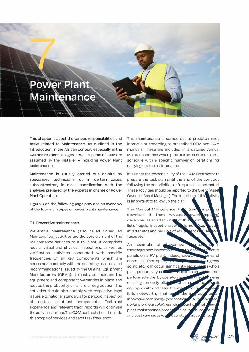
Operation & Maintenance Best Practice Guidelines / Africa edition 49
Power Plant Maintenance
7
This chapter is about the various responsibilities and tasks related to Maintenance. As outlined in the Introduction, in the African context, especially in the C&I and residential segments, all aspects of O&M are assumed by the installer – including Power Plant Maintenance.
Maintenance is usually carried out on-site by specialised technicians, or, in certain cases, subcontractors, in close coordination with the analyses prepared by the experts in charge of Power Plant Operation.
Figure 6 on the following page provides an overview of the four main types of power plant maintenance.
7.1. Preventive maintenance
Preventive Maintenance (also called Scheduled Maintenance) activities are the core element of the maintenance services to a PV plant. It comprises regular visual and physical inspections, as well as verification activities conducted with specific frequencies of all key components which are necessary to comply with the operating manuals and recommendations issued by the Original Equipment Manufacturers (OEMs). It must also maintain the equipment and component warranties in place and reduce the probability of failure or degradation. The activities should also comply with respective legal issues e.g. national standards for periodic inspection of certain electrical components. Technical experience and relevant track records will optimise the activities further. The O&M contract should include this scope of services and each task frequency.
This maintenance is carried out at predetermined intervals or according to prescribed OEM and O&M manuals. These are included in a detailed Annual Maintenance Plan which provides an established time schedule with a specific number of iterations for carrying out the maintenance.
It is under the responsibility of the O&M Contractor to prepare the task plan until the end of the contract, following the periodicities or frequencies contracted. These activities should be reported to the Client (Asset Owner or Asset Manager). The reporting of this activity is important to follow up the plan.
The “Annual Maintenance Plan” (see Annex e or download it from www.solarpowereurope.org) developed as an attachment of this report includes a list of regular inspections per equipment (e.g. module, inverter etc) and per unit of equipment (e.g. sensors, fuses etc).
An example of Preventive Maintenance is thermographic inspection aiming to identify defective panels on a PV plant. Indeed, several categories of anomalies (hot spots, hot strips, moisture ingress, soling, etc.) can occur, significantly reducing the whole plant productivity. Relevant inspection procedures are performed either by operators with handheld cameras or using remotely piloted drones or piloted aircraft equipped with dedicated thermal and optical payloads. It is noteworthy that aerial thermography as an innovative technology (see section on 13.1.1 Advanced aerial thermography), can significantly benefit power plant maintenance procedures as it can lead to time and cost savings as well as safety improvements.
© Shutterstock
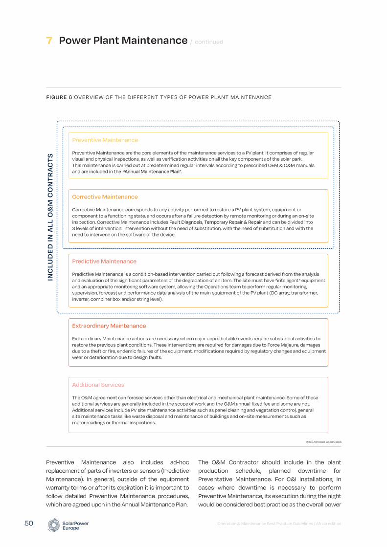
7 Power Plant Maintenance / continued
The O&M Contractor should include in the plant production schedule, planned downtime for Preventative Maintenance. For C&I installations, in cases where downtime is necessary to perform Preventive Maintenance, its execution during the night would be considered best practice as the overall power
Preventive Maintenance also includes ad-hoc replacement of parts of inverters or sensors (Predictive Maintenance). In general, outside of the equipment warranty terms or after its expiration it is important to follow detailed Preventive Maintenance procedures, which are agreed upon in the Annual Maintenance Plan.
Operation & Maintenance Best Practice Guidelines / Africa edition 50
FIGURE 6 OVERVIEW OF THE DIFFERENT TYPES OF POWER PLANT MAINTENANCE
© SOLARPOWER EUROPE 2020
INC
LUD
ED
IN A
LL O
&M
CO
NTR
AC
TS
Preventive Maintenance
Preventive Maintenance are the core elements of the maintenance services to a PV plant. It comprises of regular visual and physical inspections, as well as verification activities on all the key components of the solar park. This maintenance is carried out at predetermined regular intervals according to prescribed OEM & O&M manuals and are included in the “Annual Maintenance Plan”.
Corrective Maintenance
Corrective Maintenance corresponds to any activity performed to restore a PV plant system, equipment or component to a functioning state, and occurs after a failure detection by remote monitoring or during an on-site inspection. Corrective Maintenance includes Fault Diagnosis, Temporary Repair & Repair and can be divided into 3 levels of intervention: Intervention without the need of substitution, with the need of substitution and with the need to intervene on the software of the device.
Extraordinary Maintenance
Extraordinary Maintenance actions are necessary when major unpredictable events require substantial activities to restore the previous plant conditions. These interventions are required for damages due to Force Majeure, damages due to a theft or fire, endemic failures of the equipment, modifications required by regulatory changes and equipment wear or deterioration due to design faults.
Additional Services
The O&M agreement can foresee services other than electrical and mechanical plant maintenance. Some of these additional services are generally included in the scope of work and the O&M annual fixed fee and some are not. Additional services include PV site maintenance activities such as panel cleaning and vegetation control, general site maintenance tasks like waste disposal and maintenance of buildings and on-site measurements such as meter readings or thermal inspections.
Predictive Maintenance
Predictive Maintenance is a condition-based intervention carried out following a forecast derived from the analysis and evaluation of the significant parameters of the degradation of an item. The site must have “intelligent” equipment and an appropriate monitoring software system, allowing the Operations team to perform regular monitoring, supervision, forecast and performance data analysis of the main equipment of the PV plant (DC array, transformer, inverter, combiner box and/or string level).

physical intervention on the device in order to substitute a part of it. An example would be an inverter fan failure where the maintenance team intervenes to substitute the fan in order to restore inverter functionality.
• 3rd level: Intervention to restore device functionality with a necessity to intervene on the software of the device. In general, this kind of Corrective Maintenance includes both labour activity carried out by specialised technician (that could belong to the O&M maintenance team or be subcontracted) and, often, also an intervention on behalf of the device manufacturer’s maintenance team or of other external companies that have been licensed by the device manufacturer to intervene and restore device functionality. This activity could be included in the O&M agreement or billed separately to it, depending on the specific scope of work agreed between the parties. Generally however, this intervention is excluded by the contractual scope of work especially when the device manufacturers’ maintenance team or third party licensed company needs to intervene. By way of an example a 3rd level Corrective Maintenance could involve a device fault without apparent reason or specific broken component that could be restored only through reconfiguration or software update by the manufacturer.
The scope of Corrective Maintenance activities and its “border” or definition with respect to Preventive Maintenance requires specific attention and it should be properly defined in the Maintenance contract. For an easier comprehension, an example is presented below:
• A cable termination tightening activity using a torque device for the correct fixation should be under the Preventive Maintenance scope of works, but depending on the quantity and/or frequency, it could be considered a Corrective Maintenance activity.
Usually the Corrective Maintenance is contractually obliged to comply with contractually agreed minimum Response Times (see 11.3.3. Response Time and 12.3.2. Response Time guarantee).
Contractual agreements can foresee that the included Corrective Maintenance will be capped on a per year basis. Depending on the type of the Asset Owner being a pure financial investor or an energy producer (e.g. utility or IPP) the requirements for coverage under the Corrective Maintenance will vary.
generation is not affected. For small scale and standalone installations, this is only a recommendation.
7.2. Corrective maintenance
Corrective Maintenance covers the activities performed by the Maintenance team in order to restore a PV plant system, equipment or component to a status where it can perform the required function. The Corrective Maintenance takes place after a failure detection either by remote monitoring and supervision or during regular inspections and specific measurement activities (see Annex e).
Corrective Maintenance includes three activities:
1. Fault Diagnosis also called troubleshooting to identify fault cause and localisation.
2. Temporary Repair, to restore the required function of a faulty item for a limited time, until a Repair is carried out.
3. Repair, to restore the required function permanently.
In cases where the PV plant or segments need to be taken offline, the execution of scheduled Corrective Maintenance during night or low irradiation hours would be considered best practice as the overall power generation is not affected.
Corrective Maintenance can be divided into three levels of intervention:
• 1st level: Intervention to restore the functionality of a device without the need for substituting a component. In general, this kind of Corrective Maintenance includes only labour activity carried out by a specialised technician (that could belong to the O&M maintenance team or be subcontracted). This activity could be included in the O&M agreement or billed separately on hourly rates on top of the O&M contract, depending on the specific scope of work agreed between the parties. For example, it could consist of repairing a device that stopped due to a failure.
• 2nd level: Intervention to restore the functionality of a device that requires substitution of a component. In general, this kind of Corrective Maintenance involves labour activity carried out by a specialised technician (that could belong to the O&M maintenance team or be subcontracted) plus the
Operation & Maintenance Best Practice Guidelines / Africa edition 51

Interventions for reconditioning, renewal and technical updating, save for the cases where those actions are directly included in the scope of the contract, should be excluded from Corrective Maintenance and included in the Extraordinary Maintenance (see 7.4. Extraordinary Maintenance).
A key aspect of corrective maintenance is to be able to track failures to their root cause, which is most often a problematic manufacturer/model/serial number but may also be linked to installation errors or environmental conditions such as temperature inside enclosures; also track the efficacy of responses to problems (what fixes the problem reliably?).
7.3. Predictive maintenance
Predictive Maintenance is a special service provided by O&M Contractors who follow best practices principles. It is defined as a condition-based maintenance carried out following a forecast derived from the analysis and evaluation of the significant parameters of the degradation of the item (according to EN 13306). A prerequisite for a good Predictive Maintenance is that the devices on-site can provide information about their state, in such a way that the O&M contractor can evaluate trends or events that signal deteriorations of the device. As a best practice, the device manufacturer should provide the complete list of status and error codes produced by the device together with the detailed description of their meaning and possible impact on the function of the device. Additionally, a standardisation of status and error codes through inverters and dataloggers within a same brand should be followed and, in the future, this standardisation should be common to all manufacturers.
The Asset Owner or interested party that wants to benefit from Predictive Maintenance should, as a best practice, select “intelligent” equipment set with sufficient sensors, and opt for an appropriate monitoring software system which should be able to provide basic trending and comparison (timewise or between components and even between PV sites) functionality (minimum requirement).
The Operations team of the O&M Contractor does Predictive Maintenance thorough continuous or regular monitoring, supervision, forecast and performance data analysis (e.g. historical performance and anomalies) of the PV plant (at the
DC array, transformer, inverter, combiner box or/and string level). This can identify subtle trends that would otherwise go unnoticed until the next circuit testing or thermal imaging inspection and that indicate upcoming component or system failures or underperformance (e.g. at PV modules, inverters, combiner boxes, trackers etc level).
Before deciding which Predictive Maintenance actions to recommend, the Operations team should implement and develop procedures to effectively analyse historical data and faster identify behaviour changes that might jeopardise systems performance. These changes of behaviour are usually related to the pre-determined or unpredicted equipment degradation process. For this reason, it is important to define and to monitor all significant parameters of wear-out status, based on the sensors installed, algorithms implemented into the supervision system and other techniques.
Following such analysis, the Maintenance team can implement Predictive Maintenance activities to prevent any possible failures which can cause safety issues and energy generation loss.
For an efficient Predictive Maintenance, a certain level of maturity and experience is required, which is at best a combination of knowledge of the respective system’s performance, related equipment design, operation behaviour and relevant accumulated experience and track record from the service provider. Normally it is a process that starts after the implementation of an appropriate monitoring system and the recreation of a baseline. Such baseline will then represent the entire PV system operation as well as how equipment interacts with each other and how this system reacts to “environmental” changes.
Predictive Maintenance has several advantages, including:
• Optimising the safety management of equipment and systems during their entire lifetime.
• Anticipate maintenance activities (both corrective and preventive).
• Delay, eliminate and optimise some maintenance activities.
• Reduce time to repair and optimise maintenance and Spare Parts Management costs.
7 Power Plant Maintenance / continued
Operation & Maintenance Best Practice Guidelines / Africa edition 52
problems related to PV modules that might justify the loss of performance. This is considered as a type of Predictive Maintenance.
Example 3
The Operations team or the inverter provider monitors all critical parameters of the inverter and can provide information related to the health and performance of each individual inverter as an absolute value or as a relative comparison of different inverters at one PV site, or compare batch of inverters between different PV sites. This type of information can help O&M Contractors to operate PV sites more cost effectively without compromising the equipment health. On the other side, Asset Manager (or Owner) can also compare how inverters are aging at various sites managed by different O&M companies and evaluate how well their investment is being managed. For instance, one O&M Contractor perceived as more expensive might be providing more regular care to the inverters compared to another; as a result, the inverters are operating in better condition and are not ageing as fast, resulting in less stress and lower expected failure.
Example 4
Predictive maintenance for optimised hardware replacement cycle relying on big data analytics or artificial intelligence. For more information on this innovation, see section 13.1.3. Predictive maintenance for optimised hardware replacement.
7.4. Extraordinary maintenance
Extraordinary Maintenance actions are necessary when major unpredictable events take place in the plant that require substantial activities and works to restore the previous plant conditions or any maintenance activity generally not covered or excluded from the O&M Contract. “Force Majeure” events affecting PV plants have included high winds, flooding, hurricanes, tornados, hail, lightning and any number of other severe weather events. Extraordinary maintenance associated with severe weather include: Safety Shutdown; Inspection; Electrical Testing (integrity of circuits and grounding); Remove/repair/replace decisions; and after repairs are completed a Recommissioning confirming proper operation and documenting changes made in the repair.
• Reduce spare parts replacement costs.
• Increase availability, energy production and performance of equipment and systems.
• Reduce emergency and non-planned work.
• Improve predictability.
The following four specific examples show how Predictive Maintenance might be implemented.
Example 1
An O&M Contractor signs a new contract for a PV plant equipped with central inverters. Analysing its back-log of maintenance, the O&M Contractor knows that these inverters showed several times in the past signs of power loss due to overheating. This might be related to problems in the air flow, filter obstructions, fans or environmental changes (high temperature during summer). It was decided to monitor the temperature of IGBTs (Insulated-Gate Bipolar Transistors). Before any emergency action might be needed, in case these components have some variations in their behaviour, an “air flow inspection” is performed to detect if this change is related to the air flow. This type of activity is a condition-based inspection performed after the detection of a change in a significant parameter. It is also considered as a type of Predictive Maintenance. The final purpose is to identify if, for example, the ventilation systems will need some upgrade, replacement or if there is any type of air flow obstruction or even if it is required to anticipate replacing or cleaning the filters.
Example 2
The Operations team detects a possible underperformance of one of the sections inside the PV plant. This could be the power transformer, the inverter or some particular PV generator area that presents a lower performance when compared with others in the same conditions (or past behaviours evidence of loss of production). After the anomaly detection or recognition, an incident is created and immediately sent to the Maintenance team. Before anything happens that might jeopardise contractual guarantees and might need urgent interventions, the O&M Contractor decides to do a “General Infrared Inspection” in the PV field taking general pictures with drones, also known as drones or manned aircraft. The main purpose of this inspection is to identify possible
Operation & Maintenance Best Practice Guidelines / Africa edition 53

Generally, these activities are billed separately in the O&M contract and are managed under a separate order. It is advisable that the O&M contract includes the rules agreed among the parties to prepare the quotation and to execute the works. Both a “lump sum turn-key” or a “cost-plus” method can be used for such purposes.
Extraordinary Maintenance interventions are required for:
• Damages that are a consequence of a Force Majeure event.
• Damages as a consequence of a theft or fire.
• Serial defects or endemic failures3 on equipment, occurring suddenly and after months or years from plant start-up.
• Modifications required by regulatory changes.
In case the O&M Contractor was not the EPC of the plant, it is to be considered that also the following occurrence is an Extraordinary Maintenance:
• Major issues of which O&M Contractor becomes aware during its ordinary activity i.e. defects or other problems that are not a consequence of equipment wear or deterioration and that are not of the O&M Contractor’s responsibility because they can be reasonably considered to have been caused by design mistakes (e.g. “hidden” defects that require re-engineering).
Although not necessarily maintenance interventions, also the following revamping and repowering can also be included in the Extraordinary Maintenance list in the O&M agreement, or at least managed with the same rules. For more information on this, see Chapter 8. Revamping and repowering.
After the approval by the Asset Owner of the O&M Contractor’s proposal, activities may commence, subject to availability of the required equipment and special machinery (if required).
The potential loss of energy between the event occurrence and full repair generally cannot be considered in the SPV financial model, but it has to be considered that many of the above events are reimbursed to the Asset Owner by the insurance company under any “All Risk Insurance” coverage that is in place.
Best Practices of O&M agreements regarding Extraordinary Maintenance activities include:
• General rules to quantify price and to elaborate a schedule to perform repair activities, and the right of the Asset Owner to ask for third party quotations to compare to the quotation of the O&M Contractor; in this case a “right-to-match” option should be granted to the O&M Contractor.
• The obligation for the Asset Owner to have in place a consistent “All Risk Property” Insurance including loss of profit.
7.5. Additional services
The O&M agreement can foresee services other than those pertaining to electrical and mechanical plant maintenance as per the above sections. Some of these additional services are generally included in the scope of work and the O&M annual fixed fee and some are not.
Additional services not included in the O&M contract scope of work can be requested on demand and can either be priced per service action or based on hourly rates applicable to the level of qualification of staff required to perform the works. These hourly rates usually escalate at the same rate as the O&M Service fee. In some cases, a binding price list for the delivery of some of these additional services can be included in the O&M contract as well.
For example, regular module cleaning is an important part of solar maintenance and the problems associated with soiled modules is often underestimated. By way of example, just the effect of soiling resulting from regular wind induced dust carryover can result in a performance loss of 10%+ within 2 weeks, and of 30%+ within a matter of 6 weeks. Prolonged periods of time between cleans can result in bird droppings etching modules and lichen growth, both of which can be extremely difficult to remove. Module cleaning methods vary from manual, robotic and mechanical. Each have their own advantages and disadvantages. Cleaning frequencies vary greatly on ground, rooftop and floating solar arrays. The frequency of cleaning should be decided on a site-by-site basis and it may be that certain parts of a site will need cleaning more often than other parts of the same site.
7 Power Plant Maintenance / continued
Operation & Maintenance Best Practice Guidelines / Africa edition 54
3 For a definition of endemic failures and its repercussions in terms of warranty, see → 5.3. Warranty management.
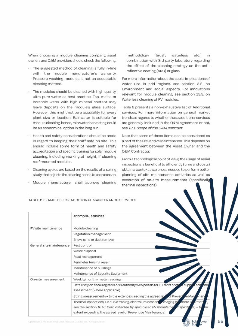
methodology (brush, waterless, etc.) in combination with 3rd party laboratory regarding the effect of the cleaning strategy on the anti-reflective coating (ARC) or glass.
For more information about the social implications of water use in arid regions, see section 3.2. on Environment and social aspects. For innovations relevant for module cleaning, see section 13.3. on Waterless cleaning of PV modules.
Table 2 presents a non-exhaustive list of Additional services. For more information on general market trends as regards to whether these additional services are generally included in the O&M agreement or not, see 12.1. Scope of the O&M contract.
Note that some of these items can be considered as a part of the Preventive Maintenance. This depends on the agreement between the Asset Owner and the O&M Contractor.
From a technological point of view, the usage of aerial inspections is beneficial to efficiently (time and costs) obtain a context awareness needed to perform better planning of site maintenance activities as well as execution of on-site measurements (specifically thermal inspections).
Operation & Maintenance Best Practice Guidelines / Africa edition 55
When choosing a module cleaning company, asset owners and O&M providers should check the following:
• The suggested method of cleaning is fully in-line with the module manufacturer’s warranty. Pressure washing modules is not an acceptable cleaning method.
• The modules should be cleaned with high quality, ultra-pure water as best practice. Tap, mains or borehole water with high mineral content may leave deposits on the module’s glass surface. However, this might not be a possibility for every plant size or location. Rainwater is suitable for module cleaning, hence, rain water harvesting could be an economical option in the long run.
• Health and safety considerations should be made in regard to keeping their staff safe on site. This should include some form of health and safety accreditation and specific training for solar module cleaning, including working at height, if cleaning roof mounted modules.
• Cleaning cycles are based on the results of a soiling study that adjusts the cleaning needs to each season.
• Module manufacturer shall approve cleaning
TABLE 2 EXAMPLES FOR ADDITIONAL MAINTENANCE SERVICES
ADDITIONAL SERVICES
PV site maintenance Module cleaning
Vegetation management
Snow, sand or dust removal
General site maintenance Pest control
Waste disposal
Road management
Perimeter fencing repair
Maintenance of buildings
Maintenance of Security Equipment
On-site measurement Weekly/monthly meter readings
Data entry on fiscal registers or in authority web portals for FIT tariff or other support scheme
assessment (where applicable).
String measurements – to the extent exceeding the agreed level of Preventive Maintenance
Thermal inspections, I-V curve tracing, electroluminescence imaging (for more information,
see the section 10.10. Data collected by specialised PV module field inspections) – to the
extent exceeding the agreed level of Preventive Maintenance.

Operation & Maintenance Best Practice Guidelines / Africa edition 56
Revamping and repowering are usually considered to be part of extraordinary maintenance from a contractual point of view – however due to their increasing significance in the solar O&M market, these Guidelines are addressing them in a standalone chapter.
8.1. Definition and rationale of revamping and repowering
Revamping and repowering are defined as the replacement of old, power production related components of a power plant by new components to enhance its overall performance. Revamping involves component replacement, but without substantially changing the plant's nominal power, whereas repowering involves increasing it. the differentiation to ordinary replacement lies in the aim to increase the performance by exchanging all components within a functional area or a significant ratio of them. the aspects and consideration in the following sections focus on repowering but apply in most cases also for revamping and even repair and extraordinary maintenance.
There are several reasons, why repowering of solar PV plants can be a necessary and/or beneficial investment. For an overview, see Figure 7 on the following page.
In the African context, Revamping and Repowering are not a major trend yet due to the relatively young age of solar PV installations. However, Revamping and Repowering are expected to become increasingly important as installations age. Some of the factors presented in the figure are increasingly relevant for the African market – such as the availability of spare parts, when equipment suppliers are not adequately
represented in certain markets. It is recommended for asset owners and O&M providers to prepare for Revamping and Repowering projects in the coming years. In certain legislations, the regulatory framework may not enable Repowering yet, however Revamping may have a strong role in African markets: for example, retrofitting installations with batteries or replacing old batteries with better ones will not involve any increase in the nominal power of the installation, however it may significantly increase its value for local communities.
There are numerous ways of repowering a PV plant. In the following we will concentrate on the two most important opportunities of module and inverter repowering.
8.2. Module repowering
Natural or increased degradation, underperformance or simple defects of modules which are not repairable or available for direct replacement on the market may force the investor to consider a module repowering. This can be carried out for the entire PV plant or for specific parts. When the repowering is focused on a partial module replacement, it is recommended to exchange some more modules than technically required, to keep some intact old modules as spare parts for the future.
Due to the fast development of PV technology it is not very likely that the same components are still available on the market in the required quantity or at a competitive price. Certainly, exchanging the identical modules would make a repowering very simple, but this would also reduce the utilisation of the repowering opportunities in lower price and higher efficiency. In case different modules are to be used for the
Revamping and Repowering
8 © Shutterstock
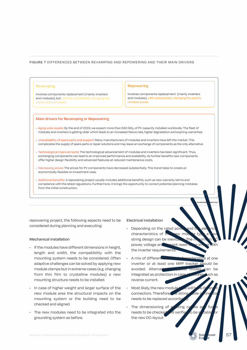
repowering project, the following aspects need to be considered during planning and executing:
Mechanical installation
• If the modules have different dimensions in height, length and width, the compatibility with the mounting system needs to be considered. Often adaptive challenges can be solved by applying new module clamps but in extreme cases (e.g. changing from thin film to crystalline modules) a new mounting structure needs to be installed.
• In case of higher weight and larger surface of the new module area the structural impacts on the mounting system or the building need to be checked and aligned.
• The new modules need to be integrated into the grounding system as before.
Electrical installation
• Depending on the rated power and the electrical characteristics of the new module type a new string design can be inevitable. The maximum DC power, voltage and current need to be in-line with the inverter requirements.
• A mix of different electrical characteristics at one inverter or at least one MPP tracker should be avoided. Alternatively, bypass diodes can be integrated as protection in case of failures such as reverse current.
• Most likely, the new module type will have different connectors. Therefore, the string cable connector needs to be replaced accordingly.
• The dimensioning of existing cables and fuses needs to be checked and verified to be suitable for the new DC-layout
Operation & Maintenance Best Practice Guidelines / Africa edition 57
FIGURE 7 DIFFERENCES BETWEEN REVAMPING AND REPOWERING AND THEIR MAIN DRIVERS
© SOLARPOWER EUROPE 2019
Revamping
Involves components replacement (mainly inverters and modules), but without substantially changing the
plant's nominal power.
Repowering
Involves components replacement (mainly inverters and modules), with substantially changing the plant's
nominal power.
Main drivers for Revamping or Repowering
• Aging solar assets: By the end of 2019, we expect more than 630 GWp of PV capacity installed worldwide. The fleet of modules and inverters is getting older which leads to an increased failure rate, higher degradation and expiring warranties.
• Unavailability of spare parts and support: Many manufacturers of modules and inverters have left the market. This complicates the supply of spare parts or repair solutions and may leave an exchange of components as the only alternative.
• Technological Improvements: The technological advancement of modules and inverters has been significant. Thus, exchanging components can lead to an improved performance and availability. As further benefits new components offer higher design flexibility and advanced features at reduced maintenance costs.
• Decreasing prices: The prices for PV components have decreased substantially. This trend helps to create an economically feasible re-investment case.
• Additional benefits: A repowering project usually includes additional benefits, such as new warranty terms and compliance with the latest regulations. Furthermore, it brings the opportunity to correct potential planning mistakes from the initial construction.
Further considerations
• A module repowering might underlie regulatory aspects, which will vary from country to country. The regulatory body should be contacted well in advance in order to clarify aspects such as:
• Maximum power to be installed
• Requirements for proving the faults of modules
• Registration of new modules
• Disposal of old modules
• Module repowering should be considered as a relevant interference into the electrical system. All affected strings should be tested and documented according to IEC 60364-7-712:2017, IEC 60364-6:2016 and IEC 62446-1:2016 after the repowering project.
• The new string layout could be optimised about shading or DC / AC ratio. Furthermore, an in-depth check of the mounting structures, cables and connectors could be performed.
• If not all modules are being exchanged and power measurements of these modules are being performed, it is recommended to install the old modules according to their remaining power. This means all modules in one string or connected to one MPP tracker should have similar power in order to reduce mismatching losses.
• Depending on the status of the old modules (and the regulatory requirements), they can be either sold to the secondary market or should be disposed or recycled by a professional provider.
8.3. Inverter repowering
As all electronic devices, inverters have a limited lifetime. With increasing age and wear, the likelihood of failures and breakdowns increases. If the warranty of the device has expired, a technically and economically suitable solution needs to be identified. Some manufacturers or service providers offer repair and spare parts services. With new components it might even be possible to increase the efficiency of an older inverter, e.g. with a replacement of an old control board with a new device with better performance characteristics, such as MPP tracking. If an identical replacement inverter, repair services or
spare parts are not available, the exchange with a new component is inevitable. There are different strategies for inverter repowering which should be evaluated on a case by case basis:
• Partial or complete exchange: If not all inverters are affected a partial exchange of the inverter fleet of the PV system can be an option. This potentially reduces the overall costs but it can also increase the complexity regarding the electrical design or the implementation of two different inverter types into one communication concept on-site. If the repowering does not affect all inverters on-site, it is advisable to store the old devices as potential spare parts. Additionally, it can be practical to exchange more inverters than technically required to store those as potential exchange devices for future defects of the old inverter type.
• Exchange of same or different power class: Exchanging inverters with the same power class is easier for the DC and AC integration. However, replacing multiple devices through one with a larger power class can increase the system efficiency and reduce the component costs as well as future maintenance costs.
When an inverter repowering is planned, several factors need to be considered:
Mechanical installation
• If the new inverters have different dimensions or weight, a suitable solution for the installation or mounting of the inverter needs to be prepared. The same accounts for a proper cabling if DC or AC connections are changed.
• The manufacturer of the new device might have different requirements for the mounting with regards to fixings, distance to other components or to the roof, ventilation, etc. All requirements need to be checked and implemented.
• The new inverters need to be integrated into the grounding system according to the standards and the manufacturers specifications.
Electrical installation
• The integration of the DC side to the new inverters needs to follow the DC input requirements of the
8 Revamping and Repowering / continued
Operation & Maintenance Best Practice Guidelines / Africa edition 58

new inverter. Eventually, the string length and the number of connected strings need to be adjusted to suit the technical parameters of maximum current and voltage as well as ideal operational conditions. In case larger inverters will be installed, additional DC combiner boxes might be required and different or additional fuses are to be integrated.
• If different inverter sizes are installed, the integration to the AC side needs to be re-engineered. This includes the cable diameters, protection devices (fuses) and connectors.
• In any case the applicable electrotechnical rules and regulations need to be followed.
Communication system
• Before choosing an adequate inverter, the compatibility with the physical communication cables should be checked.
• The installed data logger needs to support the new inverter’s data protocol. Otherwise, an update or the exchange of the data logger will be required.
• If different inverter types are installed, it can be an option to integrate the different component types on different phases of one communication cable or integrate them into one network. The compatibility of the datalogger and the monitoring platform to work with different inverter types at one PV system needs to be validated.
Further considerations
• An inverter repowering might underlie regulatory aspects, which will vary from country to country. The responsible regulatory institution should be consulted well in advance to clarify aspects such as
• Maximum power to be installed
• Compatibility to grid code and plant certificate
• Inverter repowering should be considered as a relevant interference into the electrical system. All affected cables and connectors should be tested and documented according to IEC 60364-7-712:2017, IEC 60364-6:2016 and IEC 62446-1:2016 during the repowering project
• Additional benefits may be utilised during the project. The new inverters could be optimised regarding shading or DC / AC ratio. When the new inverter has advanced features in comparison with the old inverter, e.g. multiple MPP tracker, this could be an additional advantage for the repowering project.
• The noise levels of the inverters may vary, and it should be adequately checked against the permitting and the neighbouring activities.
• Depending on the status of the old inverters, they can be either kept as potential spare parts, sold to the secondary market. If both options are not practical, the devices should be disposed or recycled by a professional service provider.
• New or different maintenance scope and intervals need to be included into the preventative maintenance schedule.
• All involved people should be informed about the changes and accordingly trained regarding preventative and reactive maintenance.
In some cases, inverter repowering is even profitable if the old inverter still operates with full availability, but a new inverter produces more energy due to higher efficiency or better operating conditions.
8.4. General repowering considerations
Although, a repowering project is mainly technically driven, for the owner of the PV system it is a commercial re-investment case. Therefore, it is of great importance to calculate a detailed and solid business case before the project and review it during the project stages. All technical and commercial data, such as historical performance, future performance, revenues, costs, extended life span and changed maintenance requirements need to be considered to come up with a prognosis of the future income streams. With this, a classical return on investment or break-even calculation can be performed and presented to the investor as a decision basis.
As an additional analysis, it is recommended to calculate the sensitivities of the most important factors. This will provide a better understanding of the influence of changing conditions, e.g. if the costs for the project will change or the projected performance will be different to the assumptions.
Operation & Maintenance Best Practice Guidelines / Africa edition 59

Each repowering activity should be approached as an individual project, which can be structured as follows:
Performance analysis
• Historical yield assessment & identification of performance issues
• Verification of issues on site with additional inspections or testing
• Determination of root causes and areas for improvement
Potential assessment
• Technical feasibility study of different options
• Commercial analysis, taking investment costs and additional revenues or reduced losses into account
• Analysis of the regulatory requirements and their implications
• Risk assessment for the case if the solution does not meet expectations
Solution Design
• Detailed technical engineering
• Determination of all costs for time and material
• Setting up project plan
• Update commercial analysis with more precise information
8 Revamping and Repowering / continued
Implementation
• Execution of repowering measures
• Project management
• Constant quality control
• Commissioning and documentation
• Update of maintenance guidelines
Review
• Technical evaluation regarding reliability and performance
• Commercial evaluation regarding costs and return on investment
A rigorous project management and quality control across all project stages will ensure a realisation of the project in time, budget and quality.
Operation & Maintenance Best Practice Guidelines / Africa edition 60

It is important to differentiate between Consumables and Spare Parts.
“Consumables” are items which are intended to be depleted or worn out relatively quickly and then replaced. they are necessary for the regular operation of the PV plant and O&M contractors should always have consumables on stock and maintenance crews should carry consumables with them, together with the relevant tools.
“Spare Parts” are all the items (materials and equipment such as modules or inverters) listed on the “Spare Parts List”, not in use or incorporated in the PV plant, intended to replace similar items in the PV plant.
Spare Parts Management is an inherent and substantial part of O&M that should ensure that spare parts are available in a timely manner for Corrective Maintenance in order to minimise the downtime of (a part of) a solar PV plant. As regards to Spare Parts Management, the following considerations have to be made:
• Ownership and responsibility of insurance
• Stocking level
• Location of storage
a. Proximity to the plant
b. Security
c. Environmental conditions
Although it is best practice for the O&M Contractor to be responsible for replenishing the spare parts stock, it is not necessarily responsible for the full cost of doing so. Some Asset Owners require O&M Contractors to be
fully responsible for the cost of all spare parts within the O&M fee, however, the more cost-effective approach is to agree which are “Included Spare Parts” and which are “Excluded Spare Parts”.
Included Spare Parts are those which the O&M Contractor is to be responsible for within the O&M fee. Excluded Spare Parts are those which the Asset Owner is responsible for the cost of replenishing and do not fall within the O&M Contractor's O&M fee. This is a flexible approach allowing the Asset Owner and O&M Contractor to agree which spare parts fall into which category. It enables both parties to have a level of cost certainty whilst balancing this with the Asset Owner's appetite for risk.
Ownership of spares is often with the Asset Owner from delivery to site or placement in the spares stock. In the case of excluded spare parts, ownership transfers to the Asset Owner from the date that the O&M Contractor receives payment for the same.
Maintenance, storage and replenishment are the responsibility of the O&M Contractor. Besides ownership matters, it is very important to make sure, upon mutual agreement, that one of the parties undertakes the responsibility of insuring the spares: as a recommendation spare parts stored on-site should be insured by the Asset Owner and spare parts stored off-site should be insured by the O&M Contractor.
For a new PV plant, the initial spare parts for two years from COD are procured by the Asset Owner or the EPC on behalf of the Asset Owner. However, it is best practice for the EPC and O&M Contractor to have agreed upon the list. The O&M Contractor should, as a
Operation & Maintenance Best Practice Guidelines / Africa edition 61
Spare Parts Management
9© sarawuth wannasathit
best practice, recommend additional spares that they deem necessary to meet the contractual obligations (e.g. availability guarantees).
Generally, it is not economically feasible to stock spare parts for every possible failure in the plant. Therefore, the O&M Contractor together with the Asset Owner should define the stocking level of specific spare parts that make economic sense (Cost-Benefit Analysis). For example, if a specific part in a solar PV plant has a frequency of failure at least of once every year or more and the loss of revenues due to such failure is greater than the spare part cost, it is important to have such a spare part kept available. Some very large O&M contractors now propose to own the spare parts in their different warehouses in replacement or addition of the asset owner spares stock. Since they operate a large number of sites, they limit the shortage of unusual spare part by maintaining a small stock.
Regarding the stocking level, due to the very different configurations and sizes of solar PV plants, it is very difficult to define a hard number for stocking specific spare parts, however 0.2% of total module quantity is often found in commercial contracts for utility-scale and large installations, and 1% (but at least 1 module) for medium-scale installations. Furthermore, the regional portfolio of the O&M Contractor might also influence this and as it was mentioned above, the determination of spare items and quantity is also driven by the O&M Contractor’s contractual commitments and guarantees.
In the African context, when setting spare parts’ stocking levels, it needs to be considered that spare parts’ availability may be more limited due to the absence of local representations of manufacturers. Issues related to logistics, the need for foreign currency in order to get new spare parts and the requirement to import spare parts from outside of the continent may contribute the higher stocking levels or spare parts strategies that favour repair instead of replacement in certain situations.
In an attempt to define the stocking levels of Spare Parts and Consumables, the following parameters should be taken into consideration:
• Frequency of failure
• Impact of failure
• Cost of Spare Part
• Degradation over time
• Possibility of consignment stock with the manufacturer
• Equipment reliability
However, for any given large C&I or utility scale solar PV system, there are certain spare parts that could be considered as essential to have – no matter the cost.
Table 3 on the following page below summarises a minimum list. This list is not exhaustive and system requirements and technology developments can lead to this list being updated following discussion with manufacturers, amongst others.
Regarding the storage and warehousing, this should be done in locations where the spare parts cannot be damaged (e.g. by humidity or high temperature variations) and are easily identifiable as being owned by the Asset Owner. Additionally, the storage sites should have appropriate security measures. The decision of having either on-site or an off-site warehouse facility or just an agreement with the suppliers to provide the spare parts, depends on many factors, including the kind of part, the commercial agreement, and the facilitation of the service provision. If the spare parts owned by the Asset Owner are stored off-site, such spares should be stored separately and be clearly identified as the property of the Asset Owner. While proximity to the plant is a parameter that needs to be evaluated on a case by case basis, security and environmental conditions are very important as they could lead to a loss of property either through thefts or damage. In the African context, high temperature variations need to be considered when storing spare parts. This may result in a more centralised spare parts storage strategy in order to enable air conditioning or heating of warehouses more cost efficiently.
9 Spare Parts Management / continued
Operation & Maintenance Best Practice Guidelines / Africa edition 62
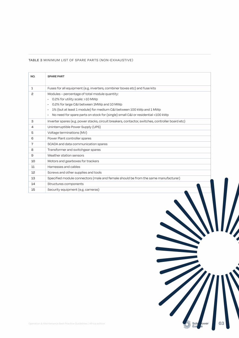
Operation & Maintenance Best Practice Guidelines / Africa edition 63
NO. SPARE PART
1 Fuses for all equipment (e.g. inverters, combiner boxes etc) and fuse kits
2 Modules – percentage of total module quantity:
• 0.2% for utility scale: >10 MWp
• 0.2% for large C&I between 1MWp and 10 MWp
• 1% (but at least 1 module) for medium C&I between 100 kWp and 1 MWp
• No need for spare parts on stock for (single) small C&I or residential <100 kWp
3 Inverter spares (e.g. power stacks, circuit breakers, contactor, switches, controller board etc)
4 Uninterruptible Power Supply (UPS)
5 Voltage terminations (MV)
6 Power Plant controller spares
7 SCADA and data communication spares
8 Transformer and switchgear spares
9 Weather station sensors
10 Motors and gearboxes for trackers
11 Harnesses and cables
12 Screws and other supplies and tools
13 Specified module connectors (male and female should be from the same manufacturer)
14 Structures components
15 Security equipment (e.g. cameras)
TABLE 3 MINIMUM LIST OF SPARE PARTS (NON-EXHAUSTIVE)

Operation & Maintenance Best Practice Guidelines / Africa edition 64
In general, the monitoring system should allow follow-up on the energy flows within a solar power plant or portfolio of (small) installations. In principle, it reports on the parameters that determine the energy conversion chain. These parameters, along with the most important energy measures in terms of yields and losses, are illustrated in the following figure. These yields and losses are always normalised to installed PV
power at standard test conditions in kilowatt-peak (kWp) for ease of performance comparison.
All components and different aspects of technical data management and monitoring platforms are described in the following paragraphs. It is also recommended to refer to the Monitoring Checklist of the Solar Best Practices Mark for a synthesis of the most important best practices and recommendation with respect to these points.4
Data & monitoring requirements
10© Ricardo Pereira
FIGURE 8 ENERGY FLOW IN A GRID-CONNECTED PHOTOVOLTAIC SYSTEM WITH PARAMETERS, YIELDS AND LOSSES5
Yr
Reference Yield
PV array
Tamb
, Tmod
, Sw
Vdc
Idc
Pdc
Vac
Iac
Pac
Inverter Grid
Gpoa
PR
Lc
Array capture
losses
Ls
System
losses
Ya
Array Yield
Yf
System Yield
© SOLARPOWER EUROPE 2020
4 The best practice checklists of the Solar Best Practices Mark are available at: www.solarbestpractices.com
5 The figure is redesigned and based on a figure produced by 3E and published in (Woyte et al. 2014).

In the African context, various factors have contributed to the increase in monitoring PV plants installed on commercial and industrial sites. These include but are not limited to:
• A decrease in the price in on-site data loggers
• Ever-increasing monitoring capabilities of on-site data loggers
• Legislation around connecting these PV plants to the local utility grid
• Insurance requirements
• Greater efficiencies achieved through comparative geo-location monitoring
The fundamentals pertaining to the smart monitoring of commercial and industrial PV power plants versus the smart monitoring of large-scale PV power plants are exactly the same. Greater deployment of machine learning, artificial intelligence and lower-cost data loggers together with the ever-increasing capabilities of these data loggers and a decrease in the price of internet connectivity throughout Africa has resulted in smaller C&I sites being able to be monitored in a similar manner as large-scale utility PV power plants.
There has been a rapid increase in the number of PV plants on C&I sites in some parts of Africa. It is now common that the same solar project company or developer has deployed PV on multiple C&I sites across the same city. Often similar equipment is used on multiple C&I sites. This phenomenon has created an opportunity to achieve greater efficiencies through a further advance of smart monitoring on these PV power plants.
10.1. Data loggers
The main purposes of a datalogger are:
• Collecting data of relevant components (inverters, meteo data, energy meter, string combiners, status signals) with every device registered separately
• Basic alarm functionality (e.g. Field Communication issues, time critical events like AC Off)
• Provide a temporary data backup (in case of missing internet connection)
• Support the technicians during commissioning (e.g. checking whether all inverters work and feed-in)
In addition to this, some dataloggers can also provide the following functions:
• Power Plant Controller (Monitoring & Control should be managed by one instance to avoid communication issues regarding concurrent access). The Power Plant Controller can be integrated in the datalogger or can be a separate device using the communication channel of the datalogger or even a separate specific one with preferential bandwidth.
• Solar Energy Trading Interface (control the active power by a third-party instance like energy trader).
As a best practice, dataloggers installed should be selected following a selection process list of criterion by the operating party as listed below. For example, an EPC Contractor will choose and install the data logger used to monitor the site. This datalogger should be selected:
• For its compatibility with the inverters and auxiliary equipment present on site. Preference for inverter-agnostic dataloggers
• For any command functionality that may be needed (this is site type and country specific)
• For its connectivity strength to the internet
• For its robustness (longevity of life and durability for the environmental conditions it will be kept in)
• For its, and the cloud server it is connected to, cyber security measures, namely the possibility to set up a VPN tunnel at least
• For its capability to store data during internet communication outages
The recording interval (also called granularity) of the datalogging should range from 1 minute to 15 minutes. Within one monitoring environment granularity should be uniform for all the different data collected.
As a minimum requirement, data loggers should store at least one month of data. Historical data should be backed up constantly by sending it to external servers and, after every communication failure, the data logger should automatically send all pending information. Moreover, data transmission should be secure and encrypted (see 10.8. Cybersecurity). There should also be a logbook to track configuration changes (especially relevant when acting as Power Plant Controller).
Operation & Maintenance Best Practice Guidelines / Africa edition 65
As a best practice, the data logger should store a minimum of three months of data locally and a full data backup in the cloud. Moreover, the operation of the data logger itself should be monitored. Such monitoring should be done out of an independent server remotely and should ideally deliver information on the status of operation of the data loggers on Operating System (OS) and hardware level and also provide alerts to the Operations room in case of failures and communication loss.
Best practice is to have dataloggers and routers constantly monitored. In the case of an error the staff on site will be informed and may restart or repair the equipment. Alternatively, a watchdog device could be used.
As a minimum requirement, the entire monitoring installation should be protected by an uninterruptable power supply (UPS). This includes data loggers, network switches, internet modems/routers, measurement devices and signal converters.
For more information, see also IEC 61724-1 Photovoltaic system performance – Part 1: Monitoring.
10.2. Monitoring portal
The main purposes of the Monitoring Portal are:
• Reading any type of raw data coming from any type of datalogger or other PV platforms with no preference on brands and models.
• Long-term archive for all raw data provided by the asset.
• Modelling each PV asset using all available information regarding the actual set up and devices (type of devices, installation/replacement date, modules-string-inverter system layout, modules inclination, orientation, type of installation etc.).
• Visualisation of aggregated data in the highest possible granularity (1 to 15 min is a best practice for most of the indicators).
• Visualisation of data in standard and specific diagrams.
• Computation and visualisation on dashboards and views of Key Performance Indicators . For the list of indicators to be computed, see Chapter 11. Indicators computational inputs might be selectable by the user.
• For the list of indicators to be computed, see Chapter 11. Indicators computational inputs might be selectable by the user.
• Validation of data quality (e.g. through calculation of data availability).
• Detection of malfunctions as well as long term degradations with customisable alarms.
• Handling of alerts from field devices like dataloggers or inverters.
• Calculate typical Key Performance Indicators (such as Performance Ratio and Availability) with the possibility to adapt parameters.
• Provision of consistent and easy to use aggregated KPI for the set up of customizable reports for single plants as well as for portfolios.
• Making data available via a standardised interface for use in other systems.
The monitoring portal should fulfil the following minimum requirements:
• Accessibility level of at least 99% across the year.
• Interface and/or apps dedicated to use cases (on-site service, investor etc).
• Customisable user Access Level.
• Graphs of irradiation, energy production, performance and yield.
• Downloadable tables with all the registered figures.
• Alarms register.
As best practice, the following features will also be included in the Monitoring Portal:
• Configurable User Interface to adjust the views depending on the target group (e.g. O&M Manager, EPC, Investor, Asset Manager).
• User configurable alarms.
• User configurable reports.
• Ticket system to handle alarm messages.
• Plant specific KPIs.
• Integrate Third Party Data (e.g. Solar power forecast, Weather data, Satellite data for irradiance).
10 Data and monitoring requirements / continued
Operation & Maintenance Best Practice Guidelines / Africa edition 66
clearly documented. Data loggers should collect all inverter alarms in accordance with original manufacturers format so that all available information is obtained.
10.4. Configuration
The configuration of the monitoring systems and data loggers needs to reflect the actual layout of plant details (hardware brand, model, installation details such as orientation, wiring losses, set up date, ..) in order to perform the better expected performances simulation and obtain consistent insight about plant actual status. Whenever this is not done during the plant construction phase, it should be done at commissioning phase or at plant takeover by a new O&M Contractor (recommissioning of the monitoring system).
During commissioning, each single equipment monitored should be checked to make sure it is properly labelled in the Monitoring System, this can be done by temporarily covering insolation sensors or switching off others such as string boxes or inverters.
The best practice is to have a Monitoring System capable to read and record all IDs from all sensors and equipment monitored, which will reduce the possibility of mislabelling elements and to trace equipment and sensor replacement along the life of the facility. Some Monitoring Systems have even an auto-configuration feature (plug-and-play) that reduces start-up time and potential mistakes. This it is done by capturing automatically the device ID and configuration information. This also allows for automatic inverter or sensor replacement detection.
10.5. Interoperability
As best practice, the system should ensure open data accessibility (bilateral possibility to receive and send data), in order to enable easy transition and communication between monitoring platforms. Table 4 shows some examples of data integration options. Because of the lack of unifying standards, this is normally not the case and every Monitoring System provider has its own method to store and retrieve data. Best practice systems have the possibility to retrieve data by using open interfaces such as RESTful, providing interoperability between different systems.
• Granularity of data should be adaptable for downloads of figures and tables.
The above lists are not exhaustive. For a comprehensive overview of recommended functionalities, refer to the Monitoring Checklist of the Solar Best Practices Mark.6
In the context of monitoring larger portfolios of (small to medium) PV systems – in Africa –, each C&I site is pinned using a geo-location. The type of PV equipment used on the site is recorded. Data loggers are installed. However, C&I smart monitoring will probably differ from large-scale PV plant monitoring because of the following:
• Multiple weather stations are installed across the city by the same PV developer.
• The PV developer will perform research and use local knowledge to divide the city into zones, taking into account any micro-climatic or geographical factors which can influence the yield of a PV plant on a C&I site. These factors may include but are not limited to mountains, urban-forests and distance from the ocean.
• Individual solar project companies or developers can now perform comparative monitoring of PV plants within these defined zones within a city and compare one PV plant to another.
a. In this manner underperformance of specific PV plants can be quickly and efficiently identified.
b. Rapid response mechanisms can be put into place whereby faults can be quickly identified and addressed.
c. Through this constant monitoring and quicker response to problem solving the yield of the PV plant can be maximised and greater efficiencies achieved.
Over time the comparative analysis can be further developed using algorithms and machine learning to warn of any performance issues. Furthermore, over time, annual yield comparisons per site can be used to further advance these algorithms and to create predictive yield models.
10.3. Data format
The data format of the recorded data files must respect standards such as IEC 61724 and has to be
Operation & Maintenance Best Practice Guidelines / Africa edition 67
6 The best practice checklists of the Solar Best Practices Mark are available at: www.solarbestpractices.com.
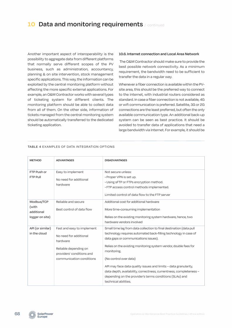
Another important aspect of interoperability is the possibility to aggregate data from different platforms that normally serve different scopes of the PV business, such as administration, accountancy, planning & on site intervention, stock management specific applications. This way, the information can be exploited by the central monitoring platform without affecting the more specific external applications. For example, an O&M Contractor works with several types of ticketing system for different clients. The monitoring platform should be able to collect data from all of them. On the other side, information of tickets managed from the central monitoring system should be automatically transferred to the dedicated ticketing application.
10.6. Internet connection and Local Area Network
The O&M Contractor should make sure to provide the best possible network connectivity. As a minimum requirement, the bandwidth need to be sufficient to transfer the data in a regular way.
Whenever a fiber connection is available within the PV-site area, this should be the preferred way to connect to the internet, with industrial routers considered as standard. In case a fiber connection is not available, 4G or wifi communication is preferred. Satellite, 3G or 2G connections are the least preferred, but often the only available communication type. An additional back-up system can be seen as best practice. It should be avoided to transfer data of applications that need a large bandwidth via Internet. For example, it should be
10 Data and monitoring requirements / continued
Operation & Maintenance Best Practice Guidelines / Africa edition 68
TABLE 4 EXAMPLES OF DATA INTEGRATION OPTIONS
METHOD ADVANTAGES DISADVANTAGES
FTP Push or
FTP Pull
Easy to implement
No need for additional
hardware
Not secure unless:
• Proper VPN is set up.
• Using sFTP or FTPs encryption method.
• FTP access control methods implemented.
Limited control of data flow to the FTP server
Modbus/TCP
(with
additional
logger on site)
Reliable and secure
Best control of data flow
Additional cost for additional hardware
More time-consuming implementation
Relies on the existing monitoring system hardware, hence, two
hardware vendors involved
API (or similar)
in the cloud
Fast and easy to implement
No need for additional
hardware
Reliable depending on
providers’ conditions and
communication conditions
Small time lag from data collection to final destination (data pull
technology requires automated back-filling technology in case of
data gaps or communications issues).
Relies on the existing monitoring system vendor, double fees for
monitoring.
(No control over data)
API may face data quality issues and limits – data granularity,
data depth, availability, correctness, currentness, completeness –
depending on the provider’s terms conditions (SLAs) and
technical abilities.
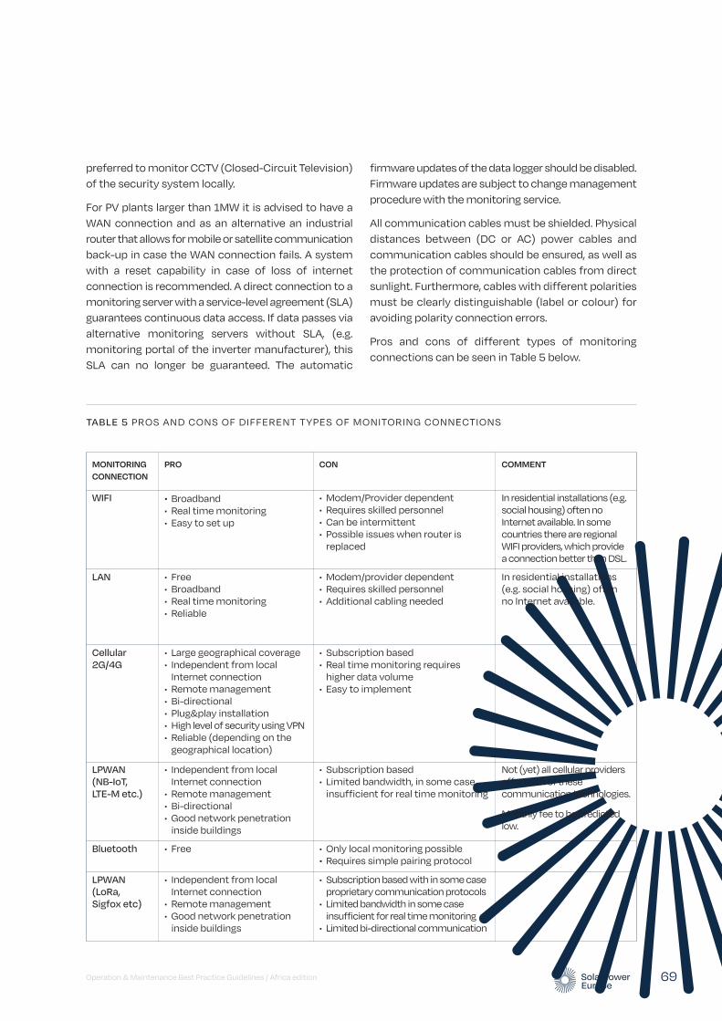
firmware updates of the data logger should be disabled. Firmware updates are subject to change management procedure with the monitoring service.
All communication cables must be shielded. Physical distances between (DC or AC) power cables and communication cables should be ensured, as well as the protection of communication cables from direct sunlight. Furthermore, cables with different polarities must be clearly distinguishable (label or colour) for avoiding polarity connection errors.
Pros and cons of different types of monitoring connections can be seen in Table 5 below.
preferred to monitor CCTV (Closed-Circuit Television) of the security system locally.
For PV plants larger than 1MW it is advised to have a WAN connection and as an alternative an industrial router that allows for mobile or satellite communication back-up in case the WAN connection fails. A system with a reset capability in case of loss of internet connection is recommended. A direct connection to a monitoring server with a service-level agreement (SLA) guarantees continuous data access. If data passes via alternative monitoring servers without SLA, (e.g. monitoring portal of the inverter manufacturer), this SLA can no longer be guaranteed. The automatic
Operation & Maintenance Best Practice Guidelines / Africa edition 69
TABLE 5 PROS AND CONS OF DIFFERENT TYPES OF MONITORING CONNECTIONS
MONITORING CONNECTION
PRO CON COMMENT
WIFI • Broadband • Real time monitoring • Easy to set up
• Modem/Provider dependent • Requires skilled personnel • Can be intermittent • Possible issues when router is
replaced
In residential installations (e.g. social housing) often no Internet available. In some countries there are regional WIFI providers, which provide a connection better than DSL.
LAN • Free • Broadband • Real time monitoring • Reliable
• Modem/provider dependent • Requires skilled personnel • Additional cabling needed
In residential installations (e.g. social housing) often no Internet available.
Cellular 2G/4G
• Large geographical coverage • Independent from local
Internet connection • Remote management • Bi-directional • Plug&play installation • High level of security using VPN • Reliable (depending on the
geographical location)
• Subscription based • Real time monitoring requires
higher data volume • Easy to implement
LPWAN (NB-IoT, LTE-M etc.)
• Independent from local Internet connection
• Remote management • Bi-directional • Good network penetration
inside buildings
• Subscription based • Limited bandwidth, in some case
insufficient for real time monitoring
Not (yet) all cellular providers offer each of these communication technologies.
Monthly fee to be predicted low.
Bluetooth • Free • Only local monitoring possible • Requires simple pairing protocol
LPWAN (LoRa, Sigfox etc)
• Independent from local Internet connection
• Remote management • Good network penetration
inside buildings
• Subscription based with in some case proprietary communication protocols
• Limited bandwidth in some case insufficient for real time monitoring
• Limited bi-directional communication
10.7. Data ownership and privacy
The data from the monitoring system and data loggers, even if hosted in the cloud, should always be owned by and accessible to the Asset Owner (or SPV). Stakeholders such as the O&M Contractor, the Asset Manager or auditors during due diligence phases that need the data to perform their duties should be granted access. It is also important to have at least two access levels (read-only, full access).
The monitoring system hardware can be provided by the O&M Contractor or a third-party monitoring service provider (but the monitoring system hardware remains the property of the Asset Owner as part of the installation):
• If the O&M Contractor is the monitoring service provider, the O&M Contractor has full responsibility for protecting and maintaining the data and the proper functioning of the monitoring system.
• In case of a third-party monitoring service provider, the responsibility for protecting and maintaining the data resides with the third-party monitoring service provider. The O&M Contractor should use his best endeavours to make sure the performance monitoring is correct, to the extent possible, considering best practices as mentioned in previous paragraphs. The O&M Contractor’s ability to properly maintain and use the monitoring system should be evaluated. If necessary, the O&M Contractor should be appropriately trained to use the monitoring system. Data use by third party monitoring providers should be extremely limited, i.e. for the sole purpose of correcting bugs and developing additional functions to their systems.
10..8. Cybersecurity
Since PV plants will at least include inverters and power plant controllers (and monitoring systems) and these are expected to be accessible from (i.e. connected to) the internet to enable surveillance and remote instructions by operators, they have significant exposure to cybersecurity risks.
Cybersecurity comprises technologies, processes and controls that are designed to protect systems, networks and data from cyber-attacks. Effective cyber security reduces the risk of cyber-attacks and protects organisations and individuals from the unauthorised exploitation of systems, networks and technologies.7
Cybersecurity is a vast area and multiple measures are imaginable. The following hints may help as a starting point:
• Keep it simple: If possible, reduce the type of network devices to a minimum.
• As a recommendation, traffic of the network devices may be monitored in order to detect abnormally high use of bandwidth.
• Secure physical access to the network devices and implement a secure password policy. Avoid the use of standard passwords especially, and change all factory setting passwords.
• Control access from Internet via strict firewall rules:
• Port forwarding should not be used because this is a big security gap. Only router ports that are necessary should be opened.
• Reduce remote access to the necessary use cases.
• The use of VPNs (Virtual Private Networks – a secure connection built up from the inside of the private network) is necessary.
• VPN access to the site from outside is a minimum requirement.
• A VPN server or VPN service which works without requiring a public IP on-site should be preferred.
• Each PV plant should have different passwords.
• Keep your documentation up to date to be sure that no device was forgotten.
• Use different roles to the extent possible (e.g. read only user, administration access).
• Use professional (industrial grade) hardware; only this hardware provides the security and administration functions your plant needs to be secure.
• Implement vulnerability management (i.e. identifying and remediating or mitigating vulnerabilities, especially in software and firmware):
• Improve insecure software configurations.
• The firmware and software of devices should be kept up-to-date.
10 Data and monitoring requirements / continued
Operation & Maintenance Best Practice Guidelines / Africa edition 70
7 Definition: https://www.itgovernance.co.uk/what-is-cybersecurity.
their products. Command functions should be sent using a secure VPN connection to the control device (best practice). Double authentication would be an even more secure option.
For further information, beyond the scope of this document, please look at the EU Cybersecurity Act (EC, 2019) and the European Parliament’s study “Cyber Security Strategy for the Energy Sector” (EP, 2016).
10.9. Types of data collected through the monitoring system
1.0.9.1 IIrradiance measurements
Irradiance Sensors
For solar PV installations larger than 200kWp, it is best practice to measure solar irradiance in the plane of the PV array (POA) on-site by means of at least one irradiance measurement device according to Class A quality classification and ISO 9060:2018 (ISO 9060 2018). The higher the quality of the pyranometer, the lower the uncertainty will be.
Pyranometers class A are preferred over silicon reference cells because they allow a direct comparison of the measured performance of the PV plant with the performance figures estimated in the energy yield assessment.
Irradiance sensors must be placed at the least shaded location. They must be mounted and wired in accordance with manufacturers’ guidelines. Preventive Maintenance and calibration of the sensors must follow the manufacturers’ guidelines.
The irradiance should be recorded with a granularity of up to 15 minutes (minimum requirement).
Further information on the categorisation of plant sizes and the use of appropriate measuring technology is provided in IEC 61724-1.
Satellite-based Irradiance Measurements
If ground-based irradiance sensors are not available, irradiance data from a high-quality satellite-based data service can be acquired as a minimum requirement in order to allow at least regular plant performance verifications. This is also useful, if there is low confidence on the data measured onsite by the Monitoring System. In particular, high quality satellite-based should be used
• Use anti-virus software if possible and keep it up to date.
• Avoid wireless access if it is not necessary.
• Audit your network with the help of external experts (penetration tests).
• Keep your company safe:
• Do not store passwords in plain text format, use password manager (e.g. 1Password, Keepass etc.)
• Train your employees on IT security awareness.
• Do not share access from all plants to all employees. Give access only to those who need it. This way damage can be prevented in case one employee is hacked.
• Management of leaving and moving employees; change passwords of plants which are overseen by an employee who have left the company or moved to another department.
It is therefore best practice that installations undertake a cyber security analysis, starting from a risk assessment (including analysis at the level of the system architecture) and implement a cybersecurity management system (CSMS) that incorporates a plan-do-check-act cycle. The CSMS should start from a cybersecurity policy, and definition of formal cybersecurity roles and responsibilities, and proceed to map this onto the system architecture in terms of detailed countermeasures applied at identified points (e.g. via analysis of the system in terms of zones and conduits). These detailed countermeasures will include the use of technical countermeasures such as firewalls, encrypted interfaces, authorisation and access controls, and audit/detection tools. But they will also include physical and procedural controls, for example, to restrict access to system components and to maintain awareness of new vulnerabilities affecting the system components.
As minimum requirements, loggers should not be accessible directly from the internet or should at least be protected via a firewall. Secure and restrictive connection to the data server is also important.
The manufacturer of the datalogger and the monitoring platform should provide information on penetration tests for their servers, any command protocol activation channels and security audits for
Operation & Maintenance Best Practice Guidelines / Africa edition 71
for irradiation sensor data quality assessment. The longer the period considered the lower the error will be for satellite-based irradiation data.
When satellite-based irradiance data is used, hourly granularity or less (15 minutes if possible) is recommended. The data must be retrieved once per day at least.
1.0.9.2. Module temperature measurements
Module temperature can be measured for performance analysis in KPIs such as the temperature-corrected PR (see 11.2.4. Temperature-corrected Performance Ratio).
The accuracy of the temperature sensor, including signal conditioning and acquisition done by the monitoring system hardware, should be < ±1 °C.
The temperature sensor should be stuck with appropriate and stable thermally conductive glue to the middle of the backside of the module in the middle of the array table, positioned in the centre of a cell, away from the junction box of the module (Woyte et al. 2013). The installation should be in accordance with manufacturer guidelines (e.g. respecting cabling instructions towards the datalogger).
PV module temperature is not supposed to be identical for all modules in a plant mainly due to different wind exposure. Therefore, in large plants more sensors will be required across the site because module temperature should be measured at different representative positions, e.g. for modules in the centre of the plant and for modules at edge locations where temperature variation is expected.
The granularity of module temperature data should be at least 15 minutes to perform a correct PR calculation.
1.0.9.3. Local meteorological data
It is best practice to measure ambient temperature, wind speed, rain fall and other site relevant meteorological measurement with the installation of a local meteorological station in accordance with the manufacturers’ guidelines. Ambient temperature is measured with a shielded thermometer, e.g. of the PT100 type. The shield protects the sensor from radiative heat transfer. Wind speed is measured with
10 Data and monitoring requirements / continued
an anemometer, at 10 m height above ground level.
Wind and ambient temperature data are normally not required for calculating PR unless this is a contractual requirement/agreement (e.g. according to specific recommendations such as from NREL). However, they are required when the PV plant is to be modelled in operation or in retrospect.
Additionally, whenever the module temperature measurements are not available or not suitable, wind speed and ambient temperature coupled with installation specifications can be used to retrieve a good estimation of module temperature. In this case, 15 minutes granularity of measurement is still the best practice.
For plants larger than10 MWp, it is recommended to have automated data collection of independent hourly meteo data (ambient temperature, wind speed, snow coverage, rainfall) from an independent meteo source. The reason for this is that on-site meteorological stations are subject to local phenomena and installation-specific results. Data from an independent meteo-station is less subject to this while being also more stable and robust with respect to long-term drift. They can therefore be used to evaluate the quality, and eventually replace, the on-site measurement.
Therefore, for both performance assessment and detailed analysis purposes, it is recommended to enable automated data collection from a nearby independent meteo reference. However, for performance assessment the most important measurement remains the in-plane irradiation (see 11. Key Performance Indicators).
Solar resource data derived from satellite image processing is available from several services at a nominal per-site and per time-segment (such as one week). The measurement error in satellite data might be greater than that of an on-site instrument, but is often more reliable than a mis-aligned, low class or dirty on-site pyranometer and less susceptible to soiling or tampering.
1.0.9.4. String measurements
Individual string current measurements may be deployed when not supported by the inverters. String level monitoring, as compared with inverter level, allows for more precise trouble-shooting procedures. Depending on module technology used in the plant,
Operation & Maintenance Best Practice Guidelines / Africa edition 72
It should be noted that the precision of inverter-integrated measurements is not always documented by the manufacturers and can be imprecise. For example, energy or AC power measurements taken by inverters may differ substantially from the values recorded by the energy meter. Monitoring systems and reporting should specify and be transparent about the devices used to acquire each measurement.
It is also very useful to have the Monitoring System collecting all inverter alarms as they are a valuable source of information for fault detection. Also, low importance alarms or warnings can be used for the organisation of maintenance activities and even setting up Preventive Maintenance actions.
In certain cases, the grid connection has limits that must be always respected, such as the maximum AC power that can be injected. For these cases there are two possibilities, one is to set limits using inverter parameters, the second one is to install Power Plant Controller that will change inverter parameters dynamically. In both cases it could be useful to monitor inverter parameters and to program alarms so that the O&M Contractor is notified when there is a parameter that has been changed wrongly and does not respect certain limit.
Best practice for the measurement of inverter-based variables is a 15-minute sampling and a granularity of up to 1 minute. For ad-hoc performance analysis purposes e.g. to allow the analysis of PV array performance, root cause analysis or possible MPP-tracking problems, the input DC voltage and current need to be measured and stored separately.
In general, and as best practice, all common inverter parameters should be logged by the data loggers, since there are a lot of additional important parameters such as internal temperature, isolation level etc that could be useful for O&M services.
Inverters should detect overheating of its conversion components to protect themselves under extreme or abnormal operating conditions. Therefore, it is advisable to record the temperature as provided by the inverter so that ventilation performance can be assessed.
1.0.9.6. Energy meter
One of the most important features of a Monitoring System is the automated collection of energy meter data with a granularity of up to 15 minutes. Gathering
strings can be combined (in harnesses) which can help reducing operation costs.
In order to detect problems quickly and to increase the plant uptime, it is good to install string monitoring equipment (as a recommendation). This will constantly measure the current of every string and register those measurements every up to 15 minutes. To reduce costs, the current sensor can potentially measure more than one string, but it is not recommended to parallel more than two of them.
1.0.9.5. Inverter measurements
Inverters have a big amount of values that are constantly measured by its hardware that can be interrogated from the monitoring system and registered. The data sent from the inverter to the monitoring system should, as a recommendation, be cumulative values to allow the monitoring of the overall electricity generation of the inverter even in case of outages of the monitoring system.
Recommended variables to be monitored are:
• Cumulative Energy generated (kWh)
• Instant Active Power injected (kW)
• Instant Reactive Power injected (kVAr)
• Instant Apparent Power injected (kVA)
• AC Voltage per each phase (V)
• AC Current per each phase (A)
• Power Factor / Cos Phi
• Frequency for each phase (Hz)
• Instant DC Power for each MPPT (kW)
• Instant DC Current for each MPPT (A)
• Instant DC Voltage for each MPPT (V)
• Total instant DC Power for all MPPTs (kW)
• Total instant DC Current for all MPPTs (A)
• Average instant DC Voltage for all MPPTs (V)
• Internal temperature (ºC)
• Conversion components temperature (ºC)
• Inverter failure signals
Operation & Maintenance Best Practice Guidelines / Africa edition 73

energy meter data is required for invoicing purposes but it is also the best reference for measuring energy and calculating plant PR and Yield and is much more accurate than using inverter data.
A high accuracy energy meter to measure energy produced and consumed by the plant is normally required by the utility. When this is not the case it is a best practice to install a meter with a maximum uncertainty of ± 0.5%, especially for plants > 100 kWp.
To allow data acquisition via the Monitoring System, it is recommended to have a meter with two communication bus ports as well as Automatic Meter Reading (AMR) service from the Utility or Meter Operator.
1.0.9.7. Control settings
It is important to monitor all control settings of the plant at inverter level as well as grid injection level if available. Many plants apply control settings for local grid regulation (injection management) or optimisation of the market value of the PV generation portfolio (remote control). These settings need to be monitored for reasons of contractual reporting or performance assessment.
1.0.9.8. Alarms
As a minimum requirement, the monitoring system will have the possibility of generating the following alarms and, at the user’s discretion, to have them sent by email:
• Loss of communication
• Plant stops
• Inverter stops
• Plant with Low Performance
• Inverter with Low Performance (e.g. due to overheating)
As best practice, the following alarms will also be sent by the monitoring system:
• String without current
• Plant under operation
• Discretion Alarm
• Alarm Aggregation
As a best practice, the following alarms should also be followed by the O&M Contractor, but these alarms are sent by separate systems other than the monitoring system:
• Intrusion detection
• Fire alarm detection
The above lists are not exhaustive. For a comprehensive overview of recommended functionalities, refer to the Monitoring Checklist of the Solar Best Practices Mark.8
1.0.9.9. AC circuit / Protection relay
It is recommended to monitor the status of MV switch gear and important LV switches through digital inputs. Whenever possible, it can also be useful to read and register the alarms generated by the protection relay control unit via communication bus.
10..10. Data collected by specialised PV module field inspections
Not all types of data are collected automatically through the monitoring system. Certain data are collected via on-site measurements and field inspections manually or with aerial inspections.
PV modules are engineered to produce electricity for 25-30 years and nowadays are being deployed in ever more and ever bigger large-scale PV plants. Quality assurance is the cornerstone for long-term reliability in order to maximise financial and energy returns and therefore, the need for tracking down the source of failures once the modules are installed becomes vital. For that reason, field technical inspections, such as infrared (IR) thermography, electroluminescence (EL) imaging and I-V curve tracing, are being put into practice in order to assess the quality and performance of PV modules on-site.
Such field inspections can be part of contractual preventive maintenance tasks or could be offered as additional services triggered by the O&M contractor in cases where, for example, plant underperformance is not clearly understood just by looking at the monitoring data.
10 Data and monitoring requirements / continued
Operation & Maintenance Best Practice Guidelines / Africa edition 74
8 The best practice checklists of the Solar Best Practices Mark are available at: www.solarbestpractices.com.
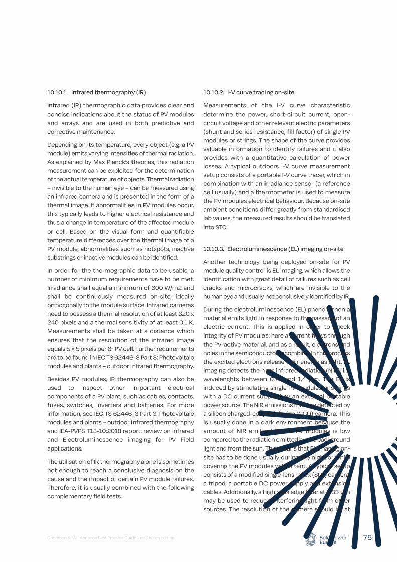
10.10.2. I-V curve tracing on-site
Measurements of the I-V curve characteristic determine the power, short-circuit current, open-circuit voltage and other relevant electric parameters (shunt and series resistance, fill factor) of single PV modules or strings. The shape of the curve provides valuable information to identify failures and it also provides with a quantitative calculation of power losses. A typical outdoors I-V curve measurement setup consists of a portable I-V curve tracer, which in combination with an irradiance sensor (a reference cell usually) and a thermometer is used to measure the PV modules electrical behaviour. Because on-site ambient conditions differ greatly from standardised lab values, the measured results should be translated into STC.
10.10.3. Electroluminescence (EL) imaging on-site
Another technology being deployed on-site for PV module quality control is EL imaging, which allows the identification with great detail of failures such as cell cracks and microcracks, which are invisible to the human eye and usually not conclusively identified by IR.
During the electroluminescence (EL) phenomenon a material emits light in response to the passage of an electric current. This is applied in order to check integrity of PV modules: here a current flows through the PV-active material, and as a result, electrons and holes in the semiconductor recombine. In this process the excited electrons release their energy as light. EL imaging detects the near infrared radiation (NIR), i.e. wavelenghts between 0,75 and 1,4 µm. The EL is induced by stimulating single PV modules or strings with a DC current supplied by an external portable power source. The NIR emissions then are detected by a silicon charged-coupled device (CCD) camera. This is usually done in a dark environment because the amount of NIR emitted by the PV modules is low compared to the radiation emitted by the background light and from the sun. This means that EL imaging on-site has to be done usually during the night or while covering the PV modules with a tent. A typical setup consists of a modified single-lens reflex (SLR) camera, a tripod, a portable DC power supply and extension cables. Additionally, a high pass edge filter at 0.85 µm may be used to reduce interfering light from other sources. The resolution of the camera should be at
10.10.1. Infrared thermography (IR)
Infrared (IR) thermographic data provides clear and concise indications about the status of PV modules and arrays and are used in both predictive and corrective maintenance.
Depending on its temperature, every object (e.g. a PV module) emits varying intensities of thermal radiation. As explained by Max Planck’s theories, this radiation measurement can be exploited for the determination of the actual temperature of objects. Thermal radiation – invisible to the human eye – can be measured using an infrared camera and is presented in the form of a thermal image. If abnormalities in PV modules occur, this typically leads to higher electrical resistance and thus a change in temperature of the affected module or cell. Based on the visual form and quantifiable temperature differences over the thermal image of a PV module, abnormalities such as hotspots, inactive substrings or inactive modules can be identified.
In order for the thermographic data to be usable, a number of minimum requirements have to be met. Irradiance shall equal a minimum of 600 W/m2 and shall be continuously measured on-site, ideally orthogonally to the module surface. Infrared cameras need to possess a thermal resolution of at least 320 x 240 pixels and a thermal sensitivity of at least 0.1 K. Measurements shall be taken at a distance which ensures that the resolution of the infrared image equals 5 x 5 pixels per 6” PV cell. Further requirements are to be found in IEC TS 62446-3 Part 3: Photovoltaic modules and plants – outdoor infrared thermography.
Besides PV modules, IR thermography can also be used to inspect other important electrical components of a PV plant, such as cables, contacts, fuses, switches, inverters and batteries. For more information, see IEC TS 62446-3 Part 3: Photovoltaic modules and plants – outdoor infrared thermography and IEA-PVPS T13-10:2018 report: review on infrared and Electroluminescence imaging for PV Field applications.
The utilisation of IR thermography alone is sometimes not enough to reach a conclusive diagnosis on the cause and the impact of certain PV module failures. Therefore, it is usually combined with the following complementary field tests.
Operation & Maintenance Best Practice Guidelines / Africa edition 75
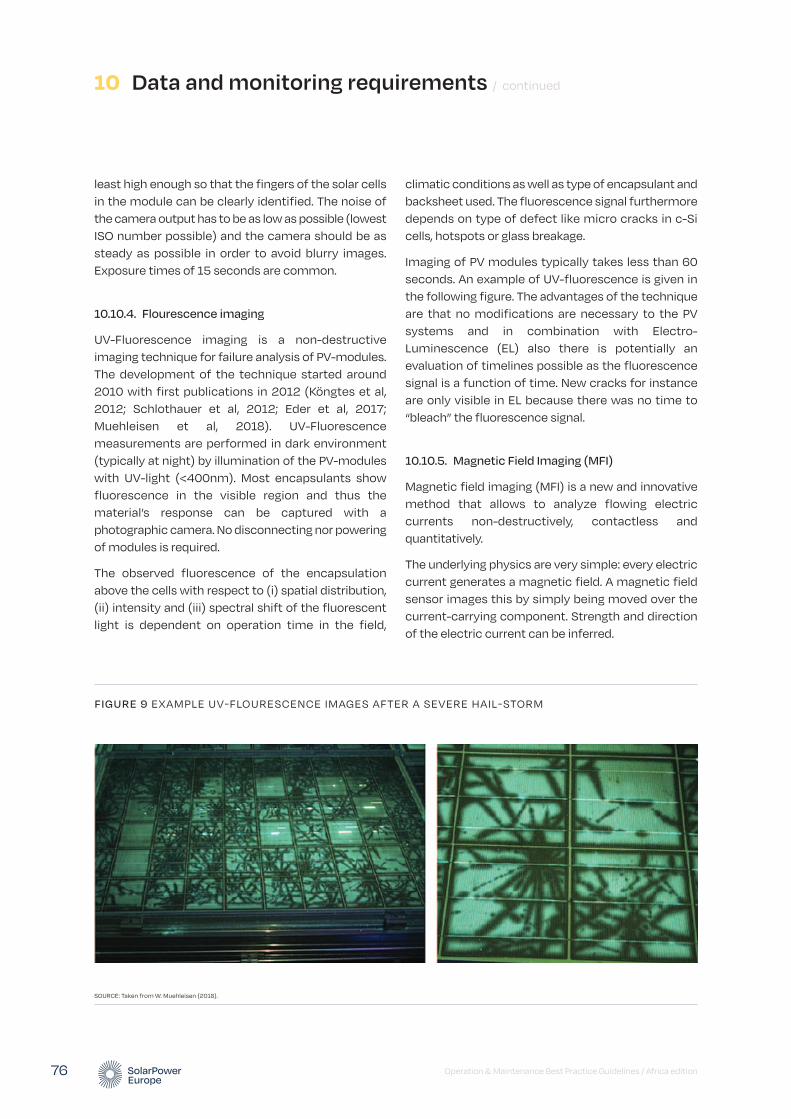
least high enough so that the fingers of the solar cells in the module can be clearly identified. The noise of the camera output has to be as low as possible (lowest ISO number possible) and the camera should be as steady as possible in order to avoid blurry images. Exposure times of 15 seconds are common.
10.10.4. Flourescence imaging
UV-Fluorescence imaging is a non-destructive imaging technique for failure analysis of PV-modules. The development of the technique started around 2010 with first publications in 2012 (Köngtes et al, 2012; Schlothauer et al, 2012; Eder et al, 2017; Muehleisen et al, 2018). UV-Fluorescence measurements are performed in dark environment (typically at night) by illumination of the PV-modules with UV-light (<400nm). Most encapsulants show fluorescence in the visible region and thus the material’s response can be captured with a photographic camera. No disconnecting nor powering of modules is required.
The observed fluorescence of the encapsulation above the cells with respect to (i) spatial distribution, (ii) intensity and (iii) spectral shift of the fluorescent light is dependent on operation time in the field,
climatic conditions as well as type of encapsulant and backsheet used. The fluorescence signal furthermore depends on type of defect like micro cracks in c-Si cells, hotspots or glass breakage.
Imaging of PV modules typically takes less than 60 seconds. An example of UV-fluorescence is given in the following figure. The advantages of the technique are that no modifications are necessary to the PV systems and in combination with Electro-Luminescence (EL) also there is potentially an evaluation of timelines possible as the fluorescence signal is a function of time. New cracks for instance are only visible in EL because there was no time to “bleach” the fluorescence signal.
10.10.5. Magnetic Field Imaging (MFI)
Magnetic field imaging (MFI) is a new and innovative method that allows to analyze flowing electric currents non-destructively, contactless and quantitatively.
The underlying physics are very simple: every electric current generates a magnetic field. A magnetic field sensor images this by simply being moved over the current-carrying component. Strength and direction of the electric current can be inferred.
10 Data and monitoring requirements / continued
Operation & Maintenance Best Practice Guidelines / Africa edition 76
FIGURE 9 EXAMPLE UV-FLOURESCENCE IMAGES AFTER A SEVERE HAIL-STORM
SOURCE: Taken from W. Muehleisen (2018).

Current-carrying components such as solar cells, modules or batteries have a characteristic current distribution. If components have defects that influence the electrical current distribution significantly, the resulting magnetic field also changes in specific ways. These changes can be detected by MFI and thus traced back to the defects.
The fields of application are manifold. In PV, defects relevant for the operation of solar modules can be detected reliably (Lauch et al, 2018; Patzold et al, 2019). These are, for example, broken connectors or ribbons (see the figure), missing solder joints or defective bypass diodes in the junction boxes of the modules.
The advantages of the measurement technique that it is non-destructive, fast and quantitative (the measurement signal is proportional to the underlying electric current). A disadvantage of using magnetic fields is that the distance to the sample must be low, in the millimeter range, to result in high quality imaging results. The measurement cannot resolve microscopic structures (< 100 µm), yet.
10.10.6. Soiling measurements
The operational efficiency of modules is affected by soiling accumulation. Soiling limits the effective irradiance and, therefore, the output of the PV module. It is recommended to measure soiling in order to optimise cleaning schedules and thus revenues. Several methodologies exist for soiling monitoring, the most basic being human inspections. A widely used soiling measurement method is using ground-based soiling reference modules consisting of a module that remains soiled, a cleaned reference cell, an automatic washing station and measurement electronics. There are several variations employing different principles to measure the effect of soiling. Upcoming digital solutions for soiling monitoring include the analysis of satellite imagery with remote sensing techniques, machine intelligence algorithms and statistical methods. Possible soiling analyses include taking a swab of the soil to an analytical laboratory to determine its nature (diesel soot; pollen; organic soil; inorganic dust) and the appropriate cleaning solution.
Operation & Maintenance Best Practice Guidelines / Africa edition 77
FIGURE 10 EXAMPLES OF MAGNETIC FIELD IMAGING (MFI)
SOURCE: Lauch et al, 2018; Patzold et al, 2019. NOTE: Left: Schematic of 3 BB solar cell, „x” indicates the position of brocken ribbon; center: Bx magnetic filed in 2D representation and more visual 3D on the right side.
Broken ribbon marked position Magnetic field measurement Magnetic field measurement (3D)
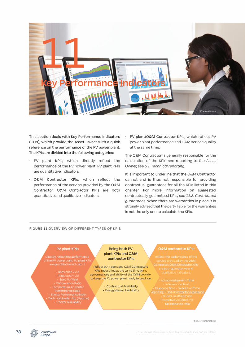
Operation & Maintenance Best Practice Guidelines / Africa edition 78
This section deals with Key Performance Indicators (KPIs), which provide the Asset Owner with a quick reference on the performance of the PV power plant. The KPIs are divided into the following categories:
• PV plant KPIs, which directly reflect the performance of the PV power plant. PV plant KPIs are quantitative indicators.
• O&M Contractor KPIs, which reflect the performance of the service provided by the O&M Contractor. O&M Contractor KPIs are both quantitative and qualitative indicators.
• PV plant/O&M Contractor KPIs, which reflect PV power plant performance and O&M service quality at the same time.
The O&M Contractor is generally responsible for the calculation of the KPIs and reporting to the Asset Owner, see 5.1. Technical reporting.
It is important to underline that the O&M Contractor cannot and is thus not responsible for providing contractual guarantees for all the KPIs listed in this chapter. For more information on suggested contractually guaranteed KPIs, see 12.3. Contractual guarantees. When there are warranties in place it is strongly advised that the party liable for the warranties is not the only one to calculate the KPIs.
Key Performance Indicators
11© Shutterstock
FIGURE 11 OVERVIEW OF DIFFERENT TYPES OF KPIS
PV plant KPIs
Directly reflect the performance of the PV power plant. PV plant KPIs
are quantitative indicators:
• Reference Yield• Expected Yield• Specific Yield
• Performance Ratio• Temperature-corrected
Performance Ratio• Energy Performance Index
• Technical Availability (Uptime)• Tracker Availability
O&M contractor KPIs
Reflect the performance of the service provided by the O&M
Contractor. O&M Contractor KPIs are both quantitative and
qualitative indicators:
• Acknowledgement Time• Intervention Time
• Response Time • Resolution Time• Reporting • O&M Contractor experience
• Schedule attainment• Preventive vs Corrective
Maintenance ratio
•• R
•R
Being both PV plant KPIs and O&M
contractor KPIs
Reflect both plant and O&M Contractors KPIs measuring at the same time plant
performances and ability of the O&M provider to keep the PV power plant ready to produce:
• Contractual Availability• Energy-Based Availability
© SOLARPOWER EUROPE 2020
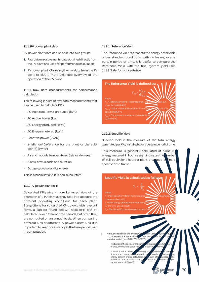
11.1. PV power plant data
PV power plant data can be split into two groups:
1. Raw data measurements: data obtained directly from the PV plant and used for performance calculation.
2. PV power plant KPIs using the raw data from the PV plant to give a more balanced overview of the operation of the PV plant.
11.1.1. Raw data measurements for performance calculation
The following is a list of raw data measurements that can be used to calculate KPIs:
• AC Apparent Power produced (kVA)
• AC Active Power (kW)
• AC Energy produced (kWh )
• AC Energy metered (kWh)
• Reactive power (kVAR)
• Irradiance9 (reference for the plant or the sub-plants) (W/m2)
• Air and module temperature (Celsius degrees)
• Alarm, status code and duration
• Outages, unavailability events
This is a basic list and it is non-exhaustive.
11.2. PV power plant KPIs
Calculated KPIs give a more balanced view of the operation of a PV plant as they take into account the different operating conditions for each plant. Suggestions for calculated KPIs along with relevant formula can be found below. These KPIs can be calculated over different time periods, but often they are computed on an annual basis. When comparing different KPIs or different PV power plants’ KPIs, it is important to keep consistency in the time period used in computation.
11.2.1. Reference Yield
The Reference Yield represents the energy obtainable under standard conditions, with no losses, over a certain period of time. It is useful to compare the Reference Yield with the final system yield (see 11.1.2.3. Performance Ratio).
11.2.2. Specific Yield
Specific Yield is the measure of the total energy generated per kWp installed over a certain period of time.
This measure is generally calculated at plant AC energy metered. In both cases it indicates the number of full equivalent hours a plant produced during a specific time frame.
Operation & Maintenance Best Practice Guidelines / Africa edition 79
9 Although irradiance and irradiation are often used as synonyms, they do not express the same physical quantities and should not be used interchangeably (see IEC 61724-1:2017):
• Irradiance is the power of the sunlight at a specific moment per unit of area, usually expressed in Watt per square meter (W/m2).
• Irradiation is the power of the sunlight integrated over a period of time, e.g. an hour, a day or a year. In other words, irradiation is the energy per unit of area calculated as the sum of irradiances over a period of time. It is commonly expressed in kilowatt-hour per square meter (kWh/m2).
The Reference Yield is defined as:
Where:
Yr(i)
= Reference Yield for the time period i expressed in peak sun
hours (h) or (kWh/kW)
HPOA(i)
= Is the measured irradiation on modules’ plane for the time
period i (kWh/m2)
GSTC
= The reference irradiance at standard test conditions (STC)
(1,000 W/m2).
Yr(i) = GSTC
HPOA
Specific Yield is calculated as follows:
Where:
Yi = Plant Specific Yield for the time period i, expressed in (kWh/kWp)
or peak sun hours (h)
Ei = Plant energy production or Plant energy metered
for the time period i (kWh)
P0 = Plant Peak DC power (nominal power) (kWp)
Yi = P0
Ei

This measurement normalises plant output over a chosen time frame and thus allows the comparison of the production of plants with different nominal power or even different technologies (e.g. PV, wind, biomass etc). For example, the Specific Yield of a PV Plant can be compared against the Specific Yield of a wind plant for investment decision taking or the Specific Yield of a 5 MWp ground mounted PV plant can be compared directly to a 1 MWp double tracker PV plant’s Specific Yield.
Calculating Specific Yield on the inverter level also allows a direct comparison between inverters that may have different AC/DC conversion rates or different nominal powers. Moreover, by checking inverter level Specific Yield within a plant, it is possible to detect whether an inverter is performing worse than others.
11.2.3. Performance ratio
The Performance Ratio (PR) is a quality indicator of the PV plant. As the ratio between the actual Specific Yield and the theoretically possible Reference Yield, PR captures the overall effect of losses of the PV system when converting from nameplate DC rating to AC output. Typically, losses result from factors such as module degradation, temperature, soiling, inverter losses, transformer losses, and system and network downtime. The higher the PR is, the more energy efficient the plant is.
PR, as defined in this section, is usually used to report on longer periods of time according to the O&M contract, such as day, month or year. Based on PR, the O&M Contractor can provide recommendations to the plant owners on possible investments or interventions.
These definitions are based on (Woyte et al. 2014) in line with the IEC 61724-1:2017 and are common practice.
PR is measured for available times (see 11.4.1. Contractual Availability) at the inverter or plant level.
Note that special attention is needed when assessing the PR of overrated plants, where the output of the plant is limited by the inverter maximum AC output. In such situations and for the period that overrating takes place, PR will calculate lower than normal although there is no technical problem with the plant. Stakeholders should be careful assessing PR values for overrated plants, although the amount of overrating is normally statistically constant or with negligible differences on a yearly basis.
11.2.4. Temperature-corrected performance ratio
In some situations, such as a commissioning test or PV power plant handover from one O&M Contractor to another, PR needs to be measured over a shorter time period, such as two weeks or a month. In such situations, it is recommended to use a PR formula corrected with temperature factor in order to neutralise short-term PR fluctuation due to temperature variations from STC (25°C). As a best
11 Key Performance Indicators / continued
Operation & Maintenance Best Practice Guidelines / Africa edition 80
Performance Ratio is defined as:
Where:
PR = Performance Ratio over a year (%)
Yf = Specific Yield over a year (also called final yield)
expressed in (kWh/kWp) or peak sun hours (h)
Yr = Reference Yield over a year expressed in (kWh/kWp)
or peak sun hours (h)
PR = × 100Yr
Yf
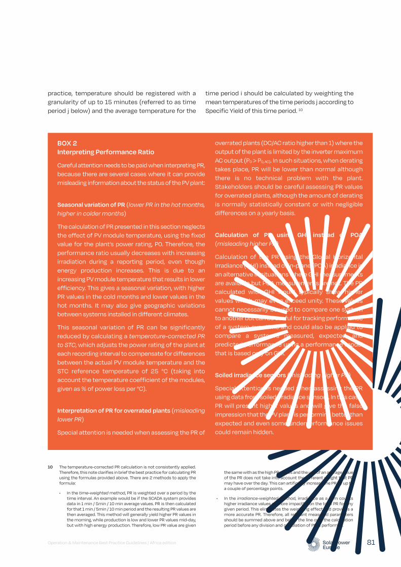
practice, temperature should be registered with a granularity of up to 15 minutes (referred to as time period j below) and the average temperature for the
time period i should be calculated by weighting the mean temperatures of the time periods j according to Specific Yield of this time period. 10
Operation & Maintenance Best Practice Guidelines / Africa edition 81
BOX 2 Interpreting Performance Ratio
Careful attention needs to be paid when interpreting PR, because there are several cases where it can provide misleading information about the status of the PV plant:
Seasonal variation of PR (lower PR in the hot months, higher in colder months)
The calculation of PR presented in this section neglects the effect of PV module temperature, using the fixed value for the plant’s power rating, P0. Therefore, the performance ratio usually decreases with increasing irradiation during a reporting period, even though energy production increases. This is due to an increasing PV module temperature that results in lower efficiency. This gives a seasonal variation, with higher PR values in the cold months and lower values in the hot months. It may also give geographic variations between systems installed in different climates.
This seasonal variation of PR can be significantly reduced by calculating a temperature-corrected PR to STC, which adjusts the power rating of the plant at each recording interval to compensate for differences between the actual PV module temperature and the STC reference temperature of 25 °C (taking into account the temperature coefficient of the modules, given as % of power loss per °C).
Interpretation of PR for overrated plants (misleading lower PR)
Special attention is needed when assessing the PR of
overrated plants (DC/AC ratio higher than 1) where the output of the plant is limited by the inverter maximum AC output (P0 > P0, AC). In such situations, when derating takes place, PR will be lower than normal although there is no technical problem with the plant. Stakeholders should be careful assessing PR values for overrated plants, although the amount of derating is normally statistically constant or with negligible differences on a yearly basis.
Calculation of PR using GHI instead of POA (misleading higher PR)
Calculation of the PR using the Global Horizontal Irradiance (GHI) instead of in-plane (POA) irradiance is an alternative in situations where GHI measurements are available but POA measurements are not. The PR calculated with GHI would typically show higher values which may even exceed unity. These values cannot necessarily be used to compare one system to another but can be useful for tracking performance of a system over time and could also be applied to compare a system’s measured, expected, and predicted performance using a performance model that is based only on GHI.
Soiled irradiance sensors (misleading higher PR)
Special attention is needed when assessing the PR using data from soiled irradiance sensors. In this case, PR will present higher values and will give the false impression that the PV plant is performing better than expected and even some underperformance issues could remain hidden.
10 The temperature-corrected PR calculation is not consistently applied. Therefore, this note clarifies in brief the best practice for calculating PR using the formulas provided above. There are 2 methods to apply the formula:
• In the time-weighted method, PR is weighted over a period by the time interval. An example would be if the SCADA system provides data in 1 min / 5min / 10 min average values. PR is then calculated for that 1 min / 5min / 10 min period and the resulting PR values are then averaged. This method will generally yield higher PR values in the morning, while production is low and lower PR values mid-day, but with high energy production. Therefore, low PR value are given
the same with as the high PR values and the use of an average value of the PR does not take into account the different weight that PR may have over the day. This can artificially increase the PR by up to a couple of percentage points.
• In the irradiance-weighted method, irradiance as a sum counts higher irradiance values as more impactful on the total PR for any given period. This eliminates the weighting effect and provides a more accurate PR. Therefore, all relevant measured parameters should be summed above and below the line over the calculation period before any division and calculation of PR is performed.
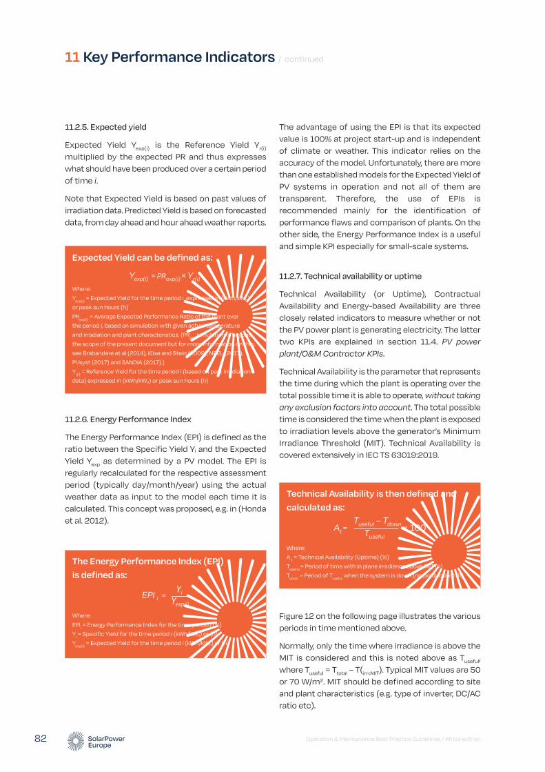
The advantage of using the EPI is that its expected value is 100% at project start-up and is independent of climate or weather. This indicator relies on the accuracy of the model. Unfortunately, there are more than one established models for the Expected Yield of PV systems in operation and not all of them are transparent. Therefore, the use of EPIs is recommended mainly for the identification of performance flaws and comparison of plants. On the other side, the Energy Performance Index is a useful and simple KPI especially for small-scale systems.
11.2.7. Technical availability or uptime
Technical Availability (or Uptime), Contractual Availability and Energy-based Availability are three closely related indicators to measure whether or not the PV power plant is generating electricity. The latter two KPIs are explained in section 11.4. PV power plant/O&M Contractor KPIs.
Technical Availability is the parameter that represents the time during which the plant is operating over the total possible time it is able to operate, without taking any exclusion factors into account. The total possible time is considered the time when the plant is exposed to irradiation levels above the generator’s Minimum Irradiance Threshold (MIT). Technical Availability is covered extensively in IEC TS 63019:2019.
Figure 12 on the following page illustrates the various periods in time mentioned above.
Normally, only the time where irradiance is above the MIT is considered and this is noted above as Tuseful, where Tuseful = Ttotal – T(irr<MIT). Typical MIT values are 50 or 70 W/m2. MIT should be defined according to site and plant characteristics (e.g. type of inverter, DC/AC ratio etc).
11 Key Performance Indicators / continued
Operation & Maintenance Best Practice Guidelines / Africa edition 82
11.2.5. Expected yield
Expected Yield Yexp(i) is the Reference Yield Yr(i) multiplied by the expected PR and thus expresses what should have been produced over a certain period of time i.
Note that Expected Yield is based on past values of irradiation data. Predicted Yield is based on forecasted data, from day ahead and hour ahead weather reports.
11.2.6. Energy Performance Index
The Energy Performance Index (EPI) is defined as the ratio between the Specific Yield Yi and the Expected Yield Yexp as determined by a PV model. The EPI is regularly recalculated for the respective assessment period (typically day/month/year) using the actual weather data as input to the model each time it is calculated. This concept was proposed, e.g. in (Honda et al. 2012).
Expected Yield can be defined as:
Where:
Yexp(i)
= Expected Yield for the time period i, expressed in (kWh/kWp)
or peak sun hours (h)
PRexp(i)
= Average Expected Performance Ratio of the plant over
the period i, based on simulation with given actual temperature
and irradiation and plant characteristics. (PRexp
simulation is beyond
the scope of the present document but for more information on this,
see Brabandere et al (2014), Klise and Stein (2009), NREL (2017),
PVsyst (2017) and SANDIA (2017).)
Yr(i)
= Reference Yield for the time period i (based on past irradiation
data) expressed in (kWh/kWp) or peak sun hours (h)
Yexp(i) = PRexp(i) × Yr(i)
The Energy Performance Index (EPI) is defined as:
Where:
EPIi = Energy Performance Index for the time period i (%)
Yi = Specific Yield for the time period i (kWh/kWp) or (h)
Yexp(i)
= Expected Yield for the time period i (kWh/kWp) or (h)
EPI i = Yexp(i)
Yi
Technical Availability is then defined and calculated as:
Where:
A t = Technical Availability (Uptime) (%)
Tuseful
= Period of time with in plane irradiance above MIT (h)
Tdown
= Period of Tuseful
when the system is down (no production) (h)
At = × 100Tuseful
Tuseful – Tdown

Operation & Maintenance Best Practice Guidelines / Africa edition 83
FIGURE 12 VARIOUS PERIODS OF TIME FOR THE CALCULATION OF THE TECHNICAL AVAILABILITY
Ttotal
Tuseful
T(irr<MIT)
Tdown
© SOLARPOWER EUROPE 2020
Technical Availability should be measured also at inverter level. Individual inverters’ Technical Availability A t k should be weighted according to their respective installed DC power Pk. In this case, the Technical Availability of the total PV power plant Attotal with an installed total DC power of P0 can be defined as follows:
For the calculation of Technical Availability, typically up to 15 minutes of irradiation and power production data should be taken as basis, if granularity of components remains at the level of inverter or higher. Anything below the level of inverter is then captured with the Performance Ratio calculation presented above.
11.2.8. Technical tracker availability or tracker uptime
Similar to Technical Availability, Technical Tracker Availability is simply a ratio of the useful time compared to the uptime or downtime of the tracker. This measurement is a pure technical parameter and
would not allow for any agreed exclusions in the availability. To calculate the technical tracker availability, the following formula can be used:
Tracking performance availability
Functional failure of a tracker can be an inaccurate tracking or out of sync tracking compared to the set point. This failure can often lead to shading or small performance deviations, based on the deviation from the sun path. The formula for the tracking performance availability is similar to the technical availability, with one small change to the classification of Tt_down. In this case the downtime is classified to any time the tracker is x (can be defined per site, depending on row spacing but ultimately can be modelled in PVSyst to give you a good general value for all seasons) degrees from the tracker set point. As long as the deviation angle is specified, this metric can be a good indicator to support the maximisation of single-or dual-axis tracking performance.
Technical Availability weighted by individual inverters’ installed DC power:
Where:
A t total
= Technical Availability of the plant (%)
A t k
= Technical Availability of the inverter k
Pk = Installed DC power of the inverter k
P0 = Plant Peak DC power (nominal power) (kWp)
At total = 100 × P0 ∑ (At k × )
Pk
Technical tracker availability is calculated as:
Where:
A t_tracker = Technical Tracker Availability (%)
Tt_down = Period of time when the tracker is down (h)
Tt_useful = Period of time when the tracker is functional (h)
At_tracker = × 100Tt_useful
Tt_useful – Tt_down
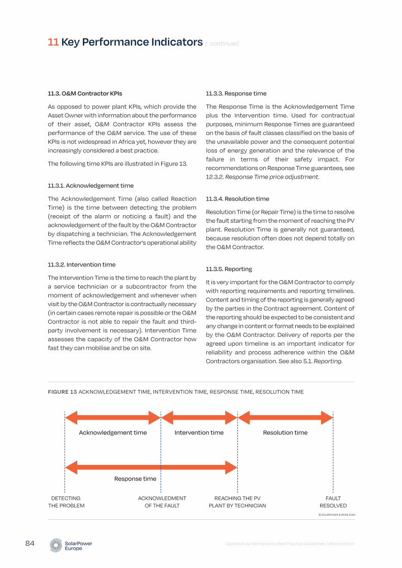
Operation & Maintenance Best Practice Guidelines / Africa edition 84
11.3. O&M Contractor KPIs
As opposed to power plant KPIs, which provide the Asset Owner with information about the performance of their asset, O&M Contractor KPIs assess the performance of the O&M service. The use of these KPIs is not widespread in Africa yet, however they are increasingly considered a best practice.
The following time KPIs are illustrated in Figure 13.
11.3.1. Acknowledgement time
The Acknowledgement Time (also called Reaction Time) is the time between detecting the problem (receipt of the alarm or noticing a fault) and the acknowledgement of the fault by the O&M Contractor by dispatching a technician. The Acknowledgement Time reflects the O&M Contractor’s operational ability
11.3.2. Intervention time
The Intervention Time is the time to reach the plant by a service technician or a subcontractor from the moment of acknowledgement and whenever when visit by the O&M Contractor is contractually necessary (in certain cases remote repair is possible or the O&M Contractor is not able to repair the fault and third-party involvement is necessary). Intervention Time assesses the capacity of the O&M Contractor how fast they can mobilise and be on site.
11.3.3. Response time
The Response Time is the Acknowledgement Time plus the Intervention time. Used for contractual purposes, minimum Response Times are guaranteed on the basis of fault classes classified on the basis of the unavailable power and the consequent potential loss of energy generation and the relevance of the failure in terms of their safety impact. For recommendations on Response Time guarantees, see 12.3.2. Response Time price adjustment.
11.3.4. Resolution time
Resolution Time (or Repair Time) is the time to resolve the fault starting from the moment of reaching the PV plant. Resolution Time is generally not guaranteed, because resolution often does not depend totally on the O&M Contractor.
11.3.5. Reporting
It is very important for the O&M Contractor to comply with reporting requirements and reporting timelines. Content and timing of the reporting is generally agreed by the parties in the Contract agreement. Content of the reporting should be expected to be consistent and any change in content or format needs to be explained by the O&M Contractor. Delivery of reports per the agreed upon timeline is an important indicator for reliability and process adherence within the O&M Contractors organisation. See also 5.1. Reporting.
11 Key Performance Indicators / continued
FIGURE 13 ACKNOWLEDGEMENT TIME, INTERVENTION TIME, RESPONSE TIME, RESOLUTION TIME
Acknowledgement time Intervention time Resolution time
DETECTING THE PROBLEM
ACKNOWLEDMENTOF THE FAULT
REACHING THE PVPLANT BY TECHNICIAN
FAULTRESOLVED
Response time
© SOLARPOWER EUROPE 2020
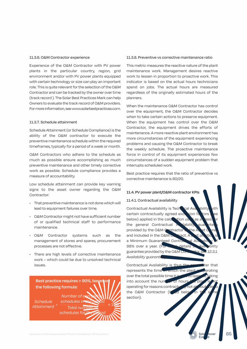
Operation & Maintenance Best Practice Guidelines / Africa edition 85
11.3.8. Preventive vs corrective maintenance ratio
This metric measures the reactive nature of the plant maintenance work. Management desires reactive work to lessen in proportion to proactive work. This indicator is based on the actual hours technicians spend on jobs. The actual hours are measured regardless of the originally estimated hours of the planners.
When the maintenance O&M Contractor has control over the equipment, the O&M Contractor decides when to take certain actions to preserve equipment. When the equipment has control over the O&M Contractor, the equipment drives the efforts of maintenance. A more reactive plant environment has more circumstances of the equipment experiencing problems and causing the O&M Contractor to break the weekly schedule. The proactive maintenance force in control of its equipment experiences few circumstances of a sudden equipment problem that interrupts scheduled work.
Best practice requires that the ratio of preventive vs corrective maintenance is 80/20.
11.4. PV power plant/O&M contractor KPIs
11.4.1. Contractual availability
Contractual Availability is Technical Availability with certain contractually agreed exclusion factors (see below) applied in the calculation used as a basis for the general Contractual Availability guarantees provided by the O&M Contractor to the Asset Owner and included in the O&M Contract. A best practice is a Minimum Guaranteed Contractual Availability of 98% over a year. (For more details on Availability guarantee provided by the O&M Contractor, see 12.3.1. Availability guarantee).
Contractual Availability is thus the parameter that represents the time in which the plant is operating over the total possible time it is able to operate, taking into account the number of hours the plant is not operating for reasons contractually not attributable to the O&M Contractor (listed below in the same section).
11.3.6. O&M Contractor experience
Experience of the O&M Contractor with PV power plants in the particular country, region, grid environment and/or with PV power plants equipped with certain technology or size can play an important role. This is quite relevant for the selection of the O&M Contractor and can be tracked by the owner over time (track record ). The Solar Best Practices Mark can help Owners to evaluate the track record of O&M providers. For more information, see www.solarbestpractices.com.
11.3.7. Schedule attainment
Schedule Attainment (or Schedule Compliance) is the ability of the O&M contractor to execute the preventive maintenance schedule within the required timeframes, typically for a period of a week or month.
O&M Contractors who adhere to the schedule as much as possible ensure accomplishing as much preventive maintenance and other timely corrective work as possible. Schedule compliance provides a measure of accountability.
Low schedule attainment can provide key warning signs to the asset owner regarding the O&M Contractor:
• That preventive maintenance is not done which will lead to equipment failures over time.
• O&M Contractor might not have sufficient number of or qualified technical staff to performance maintenance.
• O&M Contractor systems such as the management of stores and spares, procurement processes are not effective.
• There are high levels of corrective maintenance work – which could be due to unsolved technical issues.
Best practice requires > 90%, based on the following formula:
Schedule Attainment = × 100
Total number of schedules for the period
Number of completed schedules in the period

Figure 14 below illustrates the various periods in time mentioned above.
Like the Technical Availability, the Contractual Availability is also calculated for irradiance levels above the MIT and measured at inverter level. Individual inverters’ Contractual Availabilities ACk should be weighted according to their respective installed DC power Pk. In this case the Contractual Availability of the total PV power plant Ac total with an installed total DC power of P0 can be defined as follows:
For the calculation of Contractual Availability, typically up to 15 minutes of irradiation and power production data should be taken as basis, if granularity of components remains at the level of inverter or higher. Anything below the level of inverter is then captured with the Performance Ratio calculation presented above.
As Contractual Availability is used for contractual purposes, any failure time should only begin to run when the O&M Contractor receives the error message. If the data connection to the site was not available due to an external issue that is beyond the O&M Contractor’s responsibility, failure time should only begin after reestablishment of the link. However if the data connection was lost due to the unavailability of the monitoring system, the failure time should count. In general, the O&M Contractor should immediately look at the root cause of the communication loss and resolve it.
11 Key Performance Indicators / continued
Operation & Maintenance Best Practice Guidelines / Africa edition 86
Contractual Availability is therefore defined and calculated as:
Where:
Ac = Contractual Availability (%)
Tuseful
= period of time with in plane irradiance above MIT (h)
Tdown
= period of Tuseful
when the system is down (no production) (h)
Texcluded
= part of Tdown
to be excluded because of presence of an
exclusion factor (see below) (h)
Ac = × 100Tuseful
Tuseful – Tdown + Texcluded
FIGURE 14 VARIOUS PERIODS OF TIME FOR THE CALCULATION OF CONTRACTUAL AVAILABILITY11
Ttotal
Tuseful
T(irr<MIT)
Texcluded
Tdown
© SOLARPOWER EUROPE 2020
Contractual Availability weighted by individual inverters’ installed DC power:
Where:
Ac total
= Availability of the plant (%)
Ac k
= Availability of the inverter k
Pk = Installed DC power of the inverter k
P0 = Plant Peak DC power (nominal power) (kWp)
Ac total = 100 × P0 ∑ (Ac k × )
Pk
11 The Tdown
represents the whole downtime, before the exclusions are applied. Therefore, T
excluded is a part of T
down in the diagram. In practice
you often first see that a plant is down (= measurement of Tdown
) and only in the course of troubleshooting one gets the information whether you can exclude part of the downtime.
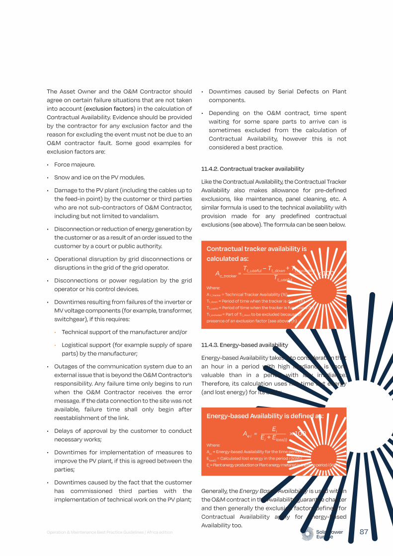
• Downtimes caused by Serial Defects on Plant components.
• Depending on the O&M contract, time spent waiting for some spare parts to arrive can is sometimes excluded from the calculation of Contractual Availability, however this is not considered a best practice.
11.4.2. Contractual tracker availability
Like the Contractual Availability, the Contractual Tracker Availability also makes allowance for pre-defined exclusions, like maintenance, panel cleaning, etc. A similar formula is used to the technical availability with provision made for any predefined contractual exclusions (see above). The formula can be seen below.
11.4.3. Energy-based availability
Energy-based Availability takes into consideration that an hour in a period with high irradiance is more valuable than in a period with low irradiance. Therefore, its calculation uses not time but energy (and lost energy) for its basis:
Generally, the Energy Based Availability is used within the O&M contract in the Availability guarantee chapter and then generally the exclusion factors defined for Contractual Availability apply for Energy-based Availability too.
The Asset Owner and the O&M Contractor should agree on certain failure situations that are not taken into account (exclusion factors) in the calculation of Contractual Availability. Evidence should be provided by the contractor for any exclusion factor and the reason for excluding the event must not be due to an O&M contractor fault. Some good examples for exclusion factors are:
• Force majeure.
• Snow and ice on the PV modules.
• Damage to the PV plant (including the cables up to the feed-in point) by the customer or third parties who are not sub-contractors of O&M Contractor, including but not limited to vandalism.
• Disconnection or reduction of energy generation by the customer or as a result of an order issued to the customer by a court or public authority.
• Operational disruption by grid disconnections or disruptions in the grid of the grid operator.
• Disconnections or power regulation by the grid operator or his control devices.
• Downtimes resulting from failures of the inverter or MV voltage components (for example, transformer, switchgear), if this requires:
• Technical support of the manufacturer and/or
• Logistical support (for example supply of spare parts) by the manufacturer;
• Outages of the communication system due to an external issue that is beyond the O&M Contractor’s responsibility. Any failure time only begins to run when the O&M Contractor receives the error message. If the data connection to the site was not available, failure time shall only begin after reestablishment of the link.
• Delays of approval by the customer to conduct necessary works;
• Downtimes for implementation of measures to improve the PV plant, if this is agreed between the parties;
• Downtimes caused by the fact that the customer has commissioned third parties with the implementation of technical work on the PV plant;
Operation & Maintenance Best Practice Guidelines / Africa edition 87
Energy-based Availability is defined as:
Where:
Ae i
= Energy-based Availability for the time period i (%)
Eloss(i)
= Calculated lost energy in the period i (kWh)
Ei = Plant energy production or Plant energy metered in the time period i (kWh)
Ae i = × 100Ei + Eloss(i)
Ei
Contractual tracker availability is calculated as:
Where:
A t_tracker = Technical Tracker Availability (%)
Tt_down = Period of time when the tracker is down (h)
Tt_useful = Period of time when the tracker is functional (h)
Tt_excluded = Part of Tt_down to be excluded because of
presence of an exclusion factor (see above) (h)
Ac_tracker = × 100Tt_useful
Tt_useful – Tt_down + Tt_excluded

The following table provides an overview of different types of Key Performance Indicators and their main purposes.
11 Key Performance Indicators / continued
Operation & Maintenance Best Practice Guidelines / Africa edition 88
TABLE 6 OVERVIEW OF DIFFERENT TYPES OF KEY PERFORMANCE INDICATORS AND THEIR PURPOSES
PV POWER PLANT KPI
O&M CONTRACTOR KPI
QUANTITATIVE QUALITATIVE 12 TO BE MONITORED WITHIN THE O&M CONTRACT
GUARANTEED IN THE O&M CONTRACT
USAGE MAIN PURPOSE
Reference Yield
✓ X ✓ X ✓ X Useful during plant designing and economic valuation
Expected Yield
✓ X ✓ X ✓ X Useful during plant designing and economic valuation
Specific Yield
✓ X ✓ X ✓ X Useful during plant designing and economic valuation
Performance Ratio
✓ X ✓ X ✓ X Useful during plant life in order to assess plant performances over time
Temperature-corrected Performance
✓ X ✓ X ✓ X Useful FAC and PAC or in other specific moment in plant life to assess plant PR starting point
Energy Performance Index
✓ X ✓ X ✓ X Useful during plant life in order to assess plant performances over time, against plant expected performance at plant designing
Technical Availability (Uptime)
✓ X ✓ X ✓ X Useful during plant life in order to assess the how much time during the time frame under analysis the plant is ready to produce
Technical Tracker Availability (Tracker Uptime)
✓ X ✓ X ✓ X Useful during plant life in order to assess the how much time during the time frame under analysis the trackers are well-functioning
Acknowledge-ment Time
X ✓ ✓ X ✓ ✓ Useful during plant operation in order to assess readiness of the O&M Provider to “realise” (detected by the monitoring system and acknowledge by the O&M provider) plant failures
Intervention Time
X ✓ ✓ X ✓ ✓ Useful during plant operation in order to assess readiness of the O&M provider to reach the plant upon a failure is “realised”
12 Qualitative data is concerned with descriptions, i.e. information that can be observed but not computed (e.g. service experience). In contrast, quantitative is measured on a numerical scale (e.g. Performance Ratio).
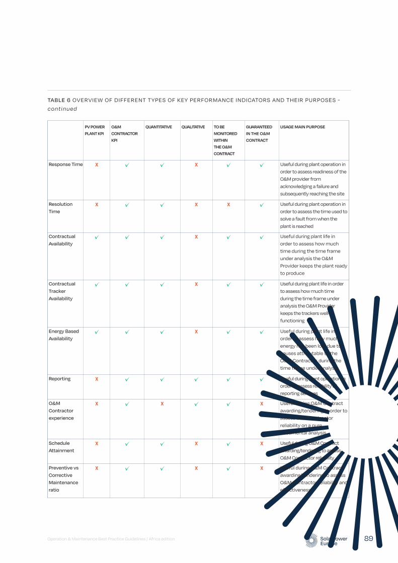
Operation & Maintenance Best Practice Guidelines / Africa edition 89
PV POWER PLANT KPI
O&M CONTRACTOR KPI
QUANTITATIVE QUALITATIVE TO BE MONITORED WITHIN THE O&M CONTRACT
GUARANTEED IN THE O&M CONTRACT
USAGE MAIN PURPOSE
Response Time X ✓ ✓ X ✓ ✓ Useful during plant operation in order to assess readiness of the O&M provider from acknowledging a failure and subsequently reaching the site
Resolution Time
X ✓ ✓ X X ✓ Useful during plant operation in order to assess the time used to solve a fault from when the plant is reached
Contractual Availability
✓ ✓ ✓ X ✓ ✓ Useful during plant life in order to assess how much time during the time frame under analysis the O&M Provider keeps the plant ready to produce
Contractual Tracker Availability
✓ ✓ ✓ X ✓ ✓ Useful during plant life in order to assess how much time during the time frame under analysis the O&M Provider keeps the trackers well-functioning
Energy Based Availability
✓ ✓ ✓ X ✓ ✓ Useful during plant life in order to assess how much energy has been lost due to causes attributable to the O&M Contractor, during the time frame under analysis
Reporting X ✓ ✓ ✓ ✓ ✓ Useful during plant operation in order to assess reliability of reporting services
O&M Contractor experience
X ✓ X ✓ ✓ X Useful during O&M Contract awarding/tendering in order to assess O&M Contractor reliability on a pure documental analysis
Schedule Attainment
X ✓ ✓ X ✓ X Useful during O&M Contract awarding/tendering to assess O&M Contractor reliability
Preventive vs Corrective Maintenance ratio
X ✓ ✓ X ✓ X Useful during O&M Contract awarding/tendering to assess O&M Contractor reliability and effectiveness
TABLE 6 OVERVIEW OF DIFFERENT TYPES OF KEY PERFORMANCE INDICATORS AND THEIR PURPOSES -
continued

Operation & Maintenance Best Practice Guidelines / Africa edition 90
This section contains a set of considerations for the contractual framework of O&M services for the small, medium and large-scale C&I and utility scale segment. For a simplified contractual framework, see section 14.4. Contractual recommendations for standalone PV systems.
A complement to the technical specifications detailed in the previous chapters, the contractual framework described in this chapter are considered as a best practice.
As a best practice, we recommend using the O&M template contract developed as part of the Open Solar Contracts suite of template contracts. This is a joint effort of the Terrawatt Initiative and the International Renewable Energy Agency. SolarPower Europe contributed to the drafting of the template O&M contract, which is one of six templates in a suite of contracts designed to be used as a package to streamline the procurement of solar projects and make it simpler to aggregate projects using standard terms. Aside from the O&M contract, the other templates include:
• Implementation Agreement
• Power Purchase Agreement
• Finance Facility Agreement term sheet
• Supply Agreement
• Installation Agreement
• Asset Management Agreement
Copies of each contract and explanatory guidance can be found at the Open Solar Contracts website: www.opensolarcontracts.org.
A common contractual framework for PV O&M is “fixed price” for specified scope of work such as administrative, operations, and preventive maintenance and then “cost plus” for corrective maintenance or additional services. For the “cost plus” part, labour rates, equipment markup, overhead and profit are negotiated in the contract and added to the actual equipment costs incurred in correcting unexpected problems.
12.1. Scope of the O&M contract
Services to be provided by the O&M Contractor include:
Technical Asset Management (Most of these services can be performed by either the O&M Contractor or the Asset Manager).
• Reporting to Asset Owner (referred to in the Open Solar Contracts templates as “Monitoring Services”, although the detail is to be determined by the parties)
• Reporting on PV plant performance
• Reporting on O&M performance
• Reporting on incidents
• Ensuring regulatory compliance
• Legal requirements for PV plant operation
• Power Purchase Agreements and Interconnection Agreements
• Power generation licence agreements
• Building permits and environmental permits
Contractual framework
12© Shutterstock
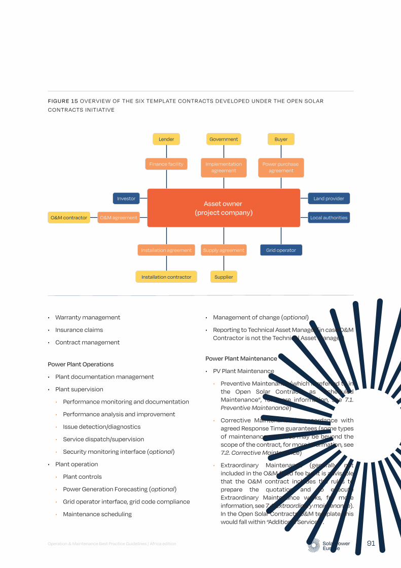
• Warranty management
• Insurance claims
• Contract management
Power Plant Operations
• Plant documentation management
• Plant supervision
• Performance monitoring and documentation
• Performance analysis and improvement
• Issue detection/diagnostics
• Service dispatch/supervision
• Security monitoring interface (optional)
• Plant operation
• Plant controls
• Power Generation Forecasting (optional)
• Grid operator interface, grid code compliance
• Maintenance scheduling
• Management of change (optional)
• Reporting to Technical Asset Manager (in case O&M Contractor is not the Technical Asset Manager)
Power Plant Maintenance
• PV Plant Maintenance
• Preventive Maintenance (which is referred to in the Open Solar Contracts as “Scheduled Maintenance”, for more information, see 7.1. Preventive Maintenance)
• Corrective Maintenance in accordance with agreed Response Time guarantees (some types of maintenance activities may be beyond the scope of the contract, for more information, see 7.2. Corrective Maintenance)
• Extraordinary Maintenance (generally not included in the O&M fixed fee but it is advisable that the O&M contract includes the rules to prepare the quotation and to execute Extraordinary Maintenance works, for more information, see 7.4. Extraordinary maintenance). In the Open Solar Contracts O&M template, this would fall within “Additional Services”.
Operation & Maintenance Best Practice Guidelines / Africa edition 91
FIGURE 15 OVERVIEW OF THE SIX TEMPLATE CONTRACTS DEVELOPED UNDER THE OPEN SOLAR
CONTRACTS INITIATIVE
Lender Government Buyer
Power purchase agreement
Installation agreement
Finance facility
Installation contractor
Implementationagreement
Supplier
Grid operator
Local authorities
Land providerAsset owner
(project company)
Supply agreement
O&M agreementO&M contractor
Investor
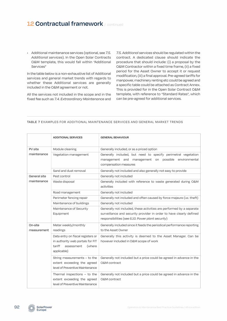
• Additional maintenance services (optional, see 7.5. Additional services). In the Open Solar Contracts O&M template, this would fall within “Additional Services”
In the table below is a non-exhaustive list of Additional services and general market trends with regards to whether these Additional services are generally included in the O&M agreement or not.
All the services not included in the scope and in the fixed fee such as 7.4. Extraordinary Maintenance and
7.5. Additional services should be regulated within the contract. A dedicated clause should indicate the procedure that should include: (i) a proposal by the O&M Contractor within a fixed time frame, (ii) a fixed period for the Asset Owner to accept it or request modification, (iii) a final approval. Pre-agreed tariffs for manpower, machinery renting etc could be agreed and a specific table could be attached as Contract Annex. This is provided for in the Open Solar Contract O&M template, with reference to “Standard Rates”, which can be pre-agreed for additional services.
12 Contractual framework / continued
Operation & Maintenance Best Practice Guidelines / Africa edition 92
TABLE 7 EXAMPLES FOR ADDITIONAL MAINTENANCE SERVICES AND GENERAL MARKET TRENDS
ADDITIONAL SERVICES GENERAL BEHAVIOUR
PV site
maintenance
Module cleaning Generally included, or as a priced option
Vegetation management Generally included, but need to specify perimetral vegetation
management and management on possible environmental
compensation measures
Sand and dust removal Generally not included and also generally not easy to provide
General site
maintenance
Pest control Generally not included
Waste disposal Generally included with reference to waste generated during O&M
activities
Road management Generally not included
Perimeter fencing repair Generally not included and often caused by force majeure (i.e.: theft)
Maintenance of buildings Generally not included
Maintenance of Security
Equipment
Generally not included, these activities are performed by a separate
surveillance and security provider in order to have clearly defined
responsibilities (see 6.10. Power plant security)
On-site
measurement
Meter weekly/monthly
readings
Generally included since it feeds the periodical performance reporting
to the Asset Owner
Data entry on fiscal registers or
in authority web portals for FIT
tariff assessment (where
applicable)
Generally this activity is deemed to the Asset Manager. Can be
however included in O&M scope of work
String measurements – to the
extent exceeding the agreed
level of Preventive Maintenance
Generally not included but a price could be agreed in advance in the
O&M contract
Thermal inspections – to the
extent exceeding the agreed
level of Preventive Maintenance
Generally not included but a price could be agreed in advance in the
O&M contract
Spare Parts Management
(See also Chapter 9 on Spare Parts Management)
• Spare parts maintenance
• Spare parts replenishment
• Spare parts storage (optional)
For more information on the specific items in the above list, please view the respective sections and chapters of the present Guidelines.
12.2. O&M contract fee
As a best practice, O&M services should be provided on a fixed fee plus escalation basis. See section 12.8 in this Chapter which discusses how spare parts management may impact on the contract fee.
12.3. Contractual guarantees and price adjustments
Although some O&M Contractors still provide Performance Ratio (PR) guarantees, recent developments including the recommendations of the Open Solar Contracts initiative, show that eliminating PR guarantee and only using Availability guarantees and Response Time price adjustments has several advantages.
PR is to a large extent a result of equipment choice, design and construction, over which a (third-party) O&M Contractor has little influence, beyond vegetation control and module cleaning. Moreover, removing PR as an O&M Contractor KPI makes power plant handover from EPC to O&M Contractor or from O&M Contractor to O&M Contractor simpler. Generally, the PR warranties are applied on projects where the O&M contractor remain the same company (or a close company) as the EPC contractor, in which case the O&M contractor carry on the risk of the technology made by its sister company.
Availability guarantees and Response Time price adjustments protect the Asset Owner from poor performing O&M Contractors. Availability is the KPI that best reflects O&M Contractor’s service. Thanks to the Response Time price adjustment, in case of events affecting the performance of the plant that are not covered by the Availability guarantee, the contractor has to intervene in a pre-agreed timeframe depending on the impact of the fault. Moreover, the O&M Contractor is also obliged to intervene in case of
incidents not affecting the performance, referring to good industry practices in general. A further upside is that it makes the transition to a new contractor much smoother and hence allows Lenders and Owners to pick a contractor of their choice and with the sole criterium of quality of services. Availability guarantees and Response Time price adjustments avoid heavy change management process due to the necessity of recalculating the guaranteed PR in case of power plant handover, which is an obstacle in the market.
Although a PR warranty is not anymore standard in the independent/third-party O&M market, it is possible to set a PR target that can trigger a joint analysis between the Asset Owner and the O&M Contractor, in order to identify causes and agrees on possible corrective actions, including revamping projects.
12.3.1. Availability guarantee
A best practice is a Minimum Guaranteed Contractual Availability of 98% over a year at least at inverter level. In certain jurisdictions, such as in Mexico, where labour legislation and the requirements of the network operator stipulate the presence of full-time technical on-site staff, a Minimum Guaranteed Availability of 99% can be provided – it should, however, be appropriately reflected in the O&M agreement’s price.
For contractual KPI reasons, Availability should be calculated at inverter level, on an annual basis. For more information on this, see 11.4.1. Contractual Availability.
The Availability achieved by the O&M Contractor is translated into Bonus Schemes and Liquidated Damages. For more information on this, see 12.4. Bonus Schemes and Liquidated Damages.
12.3.2. Response time price adjustment
The O&M Contractor should be obliged to react on alarms received from the plant through the monitoring and supervision system within a certain period of time, 7 days a week. This translates in a minimum guaranteed Response Time with the consequence of an adjustment to the contract price (the O&M fee) payable to the O&M Contractor in the event of failure to meet the Response Times. For a definition of Response Time, see 11.3.3. Response Time.
Operation & Maintenance Best Practice Guidelines / Africa edition 93

When setting a Response Time price adjustment, it is recommended to differentiate between hours and periods with high and low irradiance levels as well as fault classes, i.e. the (potential) loss of energy generation capacity or relevance in terms of safety impact of the failure.
An example for response times according to fault classes can be seen below in Table 8. (Note that this example considers a larger C&I or utility-scale solar PV power plant. In case of small-scale installations, minimum Response Times may be longer.)
In case the replacement of an equipment is needed, the O&M Contractor should commit to make it available to the plant's site and replace it within 8 business hours from the end of the Response Time, if the spare part is included in the portfolio of minimum spare parts list. If the spare part is not included in the minimum spare parts list, the O&M Contractor should commit to order the spare part within 8 business hours from the end of the Response Time and to replace it on the plant area in the fastest possible way, after receiving the related spare part from the equipment supplier.
In case the fault cannot be fixed by the O&M Contractor and the equipment supplier's intervention is required, the following actions are necessary:
• If the intervention requires spare parts up to the limit under the O&M cost responsibility (see 12.8. Spare Parts Management), the O&M Contractor may proceed without separate approval (insurance aspects to be considered).
• If the costs exceed the above budget limit, the Contractor should communicate the issue in writing to the Asset Owner within 8 business hours from the end of the Response Time.
Force Majeure events are excluded from Response Time obligations.
In the Open Solar Contracts O&M template, a failure to comply with a Response Time by more than five business days on any one occasion may also entitle an Asset Owner to terminate the O&M contract.
12.4. Bonus schemes and liquidated damages
The Availability guarantees provided by the O&M Contractor can be translated into Bonus Schemes and Liquidated Damages. The Bonus Scheme concept is referred to in the Open Solar Contract O&M template as the “Availability Bonus”. These ensure that the Asset Owner is compensated for losses due to lower-than-guaranteed Availability and that the O&M Contractor is motivated to improve their service in order to achieve higher Availability. Higher Availability usually leads to higher power generation and an increase of revenues for the benefit of the plant owner. Hence the Bonus Scheme agreements lead to a win-win situation for both parties and ensures that the O&M Contractor is highly motivated. The Open Solar Contracts O&M template provides for a list of “Excusable Events”.
Since the O&M Contractor’s responsibility is focused on the O&M works for the PV asset, other influencing factors like force majeure events, grid operator activities to reduce the plant output, grid instability or
12 Contractual framework / continued
Operation & Maintenance Best Practice Guidelines / Africa edition 94
TABLE 8 EXAMPLES FOR FAULT CLASSES AND CORRESPONDING MINIMUM RESPONSE TIMES
FAULT CLASS FAULT CLASS DEFINITION RESPONSE TIME GUARANTEE
Fault class 1 The entire plant is off, 100% power loss. 4 daytime hours
Fault class 2 More than 30% power loss or more than 300kWp down. 24 hours
Fault class 3 0%-30% power loss 36 hoursNOTE: Fault classes and the corresponding Response Time guarantees APPLIED even if the duration of the respective power loss is less than the corresponding Response Time guarantee, provided that the power loss may occur again.
offline periods should be exempted from the O&M Contractor’s responsibility and therefore from any Liquidated Damages. (See exclusion factors in 11.4.1. Contractual Availability.)
An example for Availability Bonus Schemes and Liquidated Damages can be found below:
• Bonus Schemes: if the measured availability exceeds the Minimum Guaranteed Availability, the additional revenue based on the base case scenario expected annual revenue will be divided (50/50) between the Asset Owner and the O&M Contractor in percentages previously agreed. There are also often minimum thresholds for bonuses to be due in case the overall plant energy do not meet certain target.
• Liquidated Damages: if the Minimum Guaranteed Availability is less than the measured availability, 100% of the lost revenue due to the Availability shortfall from the Minimum Guaranteed Availability based on the base case scenario expected annual revenue will be compensated by the O&M Contractor. This is usually invoiced by the Asset Owner to the O&M Contractor.
• Bonuses can be offset against Liquidated Damages and vice versa.
• The amount of Liquidated Damages should be capped at 100% of the O&M annual fee on a period of 12 months. Reaching this cap usually results in termination rights for the Asset Owner and the O&M Contractor, although in the Open Solar Contracts O&M template, the right is only given to the Asset Owner.
12.5. Service standards
O&M Contractor is to provide the services in accordance with all laws, authorisations, good industry practice, planning consents, manufacturer's warranties and operating manuals and to the standard of a reasonable and prudent operator.
The Asset Owner should be entitled to instruct a third-party operator to provide the services at the O&M Contractor's cost, where the O&M Contractor fails to provide the services and fails to follow a corrective maintenance programme.
12.6. O&M contractors’ qualification
The O&M Contractor has the means, skills and capabilities to operate and maintain the plant in accordance with the contractual obligations. Experience and availability of a professional organisation, skilled teams and access to spare parts are criteria for the selection of the O&M Contractor. As O&M services are a combination of remote operations services and local maintenance activities, the Asset Owner should make sure that both components are well managed and interfaces between operations services and maintenance services are well defined, especially when subcontracted to different entities by the O&M Contractor where each entity is responsible and can be held accountable for the overall O&M performance.
12.7. Responsibility and accountability
The responsibility of the O&M Contractor is usually defined in the Scope of Works, which forms a part of the O&M contract. In the Open Solar Contract O&M template, this is set out in the O&M Services Schedule. A detailed description of the O&M scope items ensure clarity of what the O&M Contractor will do during the term of the contract. In addition to the Scope of Works, the Annual Maintenance Plan (AMP) and Annual Maintenance Schedule (AMS) (please refer to attachment “Annual Maintenance Plan”) outline the granularity and frequency of (predominantly) Preventive Maintenance works. The execution of the activities is being reported to the Asset Owner through the regular reporting – this forms the minimum requirements. Best practices can be seen if the regular reporting compares the executed activities with the AMP and AMS, and outlines deviations and reasoning.
Corrective Maintenance activities, which will be performed in case of any component failure or energy generation shortfall, are controlled by performance commitments signed by the O&M Contractor. In the Open Solar Contracts O&M template, these are set out as “Corrective Maintenance Services”.
Moreover, the Availability Guarantee and Response Time price adjustment explained in 12.3. Contractual Guarantees and price adjustments of the present chapter also represent a level of accountability of the O&M Contractor.
Operation & Maintenance Best Practice Guidelines / Africa edition 95
In most countries there are strict legal requirements for security service providers. Therefore, PV power plant security should be ensured by specialised security service providers directly contracted by the Asset Owner or, exceptionally, subcontracted by the O&M Contractor. The security service provider should also assume liability for the security services provided. For more information on this, see 6.9. Power plant security.
12.8. Spare parts management
The Open Solar Contracts O&M template takes two approaches to Spare Parts management. Either the O&M Contractor takes full responsibility for Spare Parts or there is a distinction between “Included Spare Parts”, which are included in the O&M Contractor's fee, and “Excluded Spare Parts”, the cost of which would be payable in addition to the fee plus a pre-agreed margin. In either case, replenishing Spare Parts stock will be the O&M Contractor's responsibility, although at the Asset Owner's cost in relation to Excluded Spare Parts. This guidance considers it best practice to take the second approach of clearly identifying Included and Excluded Spare Parts, in order to find an appropriate balance between the amount of risk that the Asset Owner is willing to accept against the cost of the O&M fee.
Although it is best practice for the O&M Contractor to be responsible for replenishing the spare parts stock, it is not necessarily responsible for the full cost of doing so. Some Asset Owners require O&M Contractors to be fully responsible for the cost of all spare parts within the O&M fee, however, the more cost-effective approach is to agree which are “Included Spare Parts” and which are “Excluded Spare Parts”.
Included Spare Parts are those which the O&M Contractor is to be responsible for within the O&M fee. Excluded Spare Parts are those which the Asset Owner is responsible for the cost of replenishing and do not fall within the O&M Contractor's O&M fee. This is a flexible approach allowing the Asset Owner and O&M Contractor to agree which spare parts fall into which category. It enables both parties to have a level of cost certainty whilst balancing this with the Asset Owner's appetite for risk.
Ownership of spares is often with the Asset Owner from delivery to site or placement in the spares stock. In the case of excluded spare parts, ownership
transfers to the Asset Owner from the date that the O&M Contractor receives payment for the same.
Besides ownership matters, it is very important to make sure, upon mutual agreement, that one of the parties undertakes the responsibility of insuring the spares: as a recommendation spare parts stored on-site should be insured by the Asset Owner and spare parts stored off-site should be insured by the O&M Contractor.
There should be a components, materials and spare parts defects warranty for 12 months from the date of installation, which should continue to apply even after expiry or termination of the O&M contract.
For more information on Spare Parts Management, see the Chapter 9. Spare Parts Management.
12.9. Power plant monitoring
The O&M Contractor should operate and maintain the metering system according to local regulations or norms. In some countries there are two metering systems: one that measures power injection in the grid, owned and operated by the grid operator, and one that measures power production, owned by the Asset Owner as part of the installation and operated by the O&M Contractor.
The O&M Contractor will also make sure that performance monitoring and reporting is operated and maintained according to the monitoring specifications and best practices (see 10. Data and monitoring requirements).
The Asset Owner has the right to carry out the verification of the metering system to evaluate and control the exactitude of the measured data.
12.10. Reporting
Reporting should be done periodically, as contractually agreed between the O&M Contractor (the Technical Asset Manager) and the Asset Owner. The Asset Owner should have the right to debate the report within a certain timeframe.
For more information on industry best practices regarding Reporting, see 5.1. Technical reporting.
12 Contractual framework / continued
Operation & Maintenance Best Practice Guidelines / Africa edition 96

Operation & Maintenance Best Practice Guidelines / Africa edition 97
Innovations and trends
13
O&M contractors are increasingly relying on innovations and more machine and data-driven solutions to keep up with market requirements. Innovations in O&M services are anticipated to reduce the levelised cost of electricity (LCOE) by 0.8% to 1.4% between 2015 and 2030. The savings are dominated by improvements in OPEX and power plant availability, and hence net Annual Energy Production (source: KIC InnoEnergy, 2015).
The most important trends and innovations shaping today’s O&M market are summarised in this section, grouped into three “families”:
1. Smart PV power plant monitoring and data-driven O&M
2. Retrofit coatings for PV modules
3. Waterless cleaning of PV modules.
13.1. Smart PV power plant monitoring and data-driven O&M
Traditional monitoring systems generally consist of on-site data loggers that collect electrical data from devices installed on the PV plant inverters, strings, meters and weather data from meteorological stations. A management software then allows remote performance management, data visualisation, basic KPI calculations, reporting and alarm and ticket management.
These systems, used on their own, commonly fail to detect the root causes of underperformance. The industry is therefore rapidly moving towards the adoption of ‘smarter’ solutions based on advanced data mining techniques.
Data mining is the process of digging through data to discover hidden connections and predict trends. Sometimes referred to as “knowledge discovery in databases,” the term “data mining” was not coined until the 1990s. Its foundation is comprised of three intertwined scientific disciplines as shown in Figure 16 on the following page.
Although data mining is not a new discipline, its capabilities are now being unleashed due to the potential of big data and increasingly affordable computing power and storage. Its potential to enable O&M contractors to move beyond manual, tedious and time-consuming practices to quick, easy and automated data analysis is now becoming more tangible (source: SAS, 2018).
© BayWa r.e. renewable energy GmbH
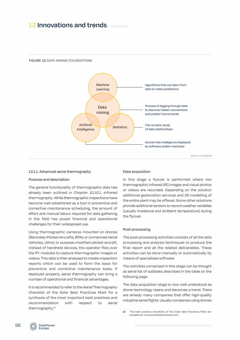
13 Innovations and trends / continued
Operation & Maintenance Best Practice Guidelines / Africa edition 98
13.1.1. Advanced aerial thermography
Purpose and description
The general functionality of thermographic data has already been outlined in Chapter 10.10.1. Infrared thermography. While thermographic inspections have become well established as a tool in preventive and corrective maintenance scheduling, the amount of effort and manual labour required for data gathering in the field has posed financial and operational challenges for their widespread use.
Using thermographic cameras mounted on drones (Remotely Piloted Aircrafts, RPAs or Unmanned Aerial Vehicles, UAVs) or purpose-modified piloted aircraft, instead of handheld devices, the operator flies over the PV modules to capture thermographic images or videos. This data is then analysed to create inspection reports which can be used to form the basis for preventive and corrective maintenance tasks. If deployed properly, aerial thermography can bring a number of operational and financial advantages.
It is recommended to refer to the Aerial Thermography Checklist of the Solar Best Practices Mark for a synthesis of the most important best practices and recommendation with respect to aerial thermography.13
Data acquisition
In this stage a flyover is performed where raw thermographic infrared (IR) images and visual photos or videos are recorded. Depending on the solution additional geolocation services and 3D modelling of the entire plant may be offered. Some other solutions provide additional sensors to record weather variables (usually irradiance and ambient temperature) during the flyover.
Post-processing
The post-processing activities consists of all the data processing and analysis techniques to produce the final report and all the related deliverables. These activities can be done manually or automatically by means of specialised software.
The activities comprised in this stage can be thought as serial list of subtasks described in the table on the following page.
The data acquisition stage is now well understood as drone technology ripens and becomes a trend. There are already many companies that offer high-quality industrial aerial flights. Usually companies using drones
FIGURE 16 DATA MINING FOUNDATIONS
Process of digging through data
to discover hidden connections
and predict future trends
Data
mining
StatisticsArtificial
Intelligence
Machine
Learning
The numeric study
of data relationships
Algorithms that can learn from
data to make predictions
Human-like intelligence displayed
by software and/or machines
Adapted from: WWW.SAS.COM
13 The best practice checklists of the Solar Best Practices Mark are available at: www.solarbestpractices.com.
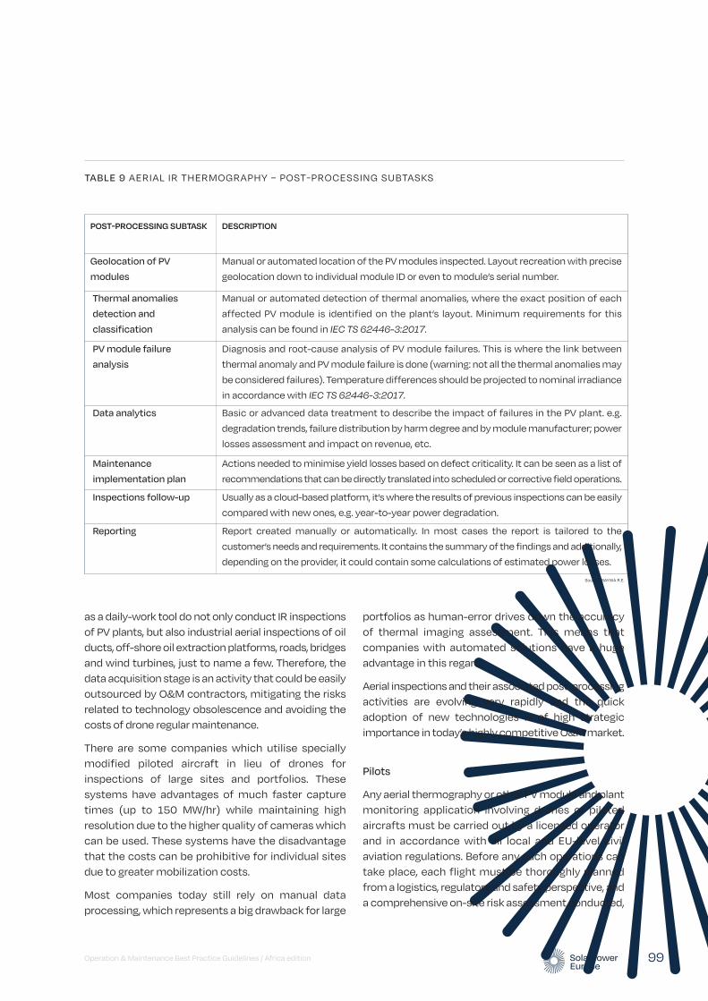
as a daily-work tool do not only conduct IR inspections of PV plants, but also industrial aerial inspections of oil ducts, off-shore oil extraction platforms, roads, bridges and wind turbines, just to name a few. Therefore, the data acquisition stage is an activity that could be easily outsourced by O&M contractors, mitigating the risks related to technology obsolescence and avoiding the costs of drone regular maintenance.
There are some companies which utilise specially modified piloted aircraft in lieu of drones for inspections of large sites and portfolios. These systems have advantages of much faster capture times (up to 150 MW/hr) while maintaining high resolution due to the higher quality of cameras which can be used. These systems have the disadvantage that the costs can be prohibitive for individual sites due to greater mobilization costs.
Most companies today still rely on manual data processing, which represents a big drawback for large
portfolios as human-error drives down the accuracy of thermal imaging assessment. This means that companies with automated solutions have a huge advantage in this regard.
Aerial inspections and their associated post-processing activities are evolving very rapidly and the quick adoption of new technologies is of high strategic importance in today’s highly competitive O&M market.
Pilots
Any aerial thermography or other PV module and plant monitoring application involving drones or piloted aircrafts must be carried out by a licensed operator and in accordance with all local and EU-level civil aviation regulations. Before any such operations can take place, each flight must be thoroughly planned from a logistics, regulatory and safety perspective, and a comprehensive on-site risk assessment conducted,
Operation & Maintenance Best Practice Guidelines / Africa edition 99
POST-PROCESSING SUBTASK DESCRIPTION
Geolocation of PV
modules
Manual or automated location of the PV modules inspected. Layout recreation with precise
geolocation down to individual module ID or even to module’s serial number.
Thermal anomalies
detection and
classification
Manual or automated detection of thermal anomalies, where the exact position of each
affected PV module is identified on the plant’s layout. Minimum requirements for this
analysis can be found in IEC TS 62446-3:2017.
PV module failure
analysis
Diagnosis and root-cause analysis of PV module failures. This is where the link between
thermal anomaly and PV module failure is done (warning: not all the thermal anomalies may
be considered failures). Temperature differences should be projected to nominal irradiance
in accordance with IEC TS 62446-3:2017.
Data analytics Basic or advanced data treatment to describe the impact of failures in the PV plant. e.g.
degradation trends, failure distribution by harm degree and by module manufacturer; power
losses assessment and impact on revenue, etc.
Maintenance
implementation plan
Actions needed to minimise yield losses based on defect criticality. It can be seen as a list of
recommendations that can be directly translated into scheduled or corrective field operations.
Inspections follow-up Usually as a cloud-based platform, it’s where the results of previous inspections can be easily
compared with new ones, e.g. year-to-year power degradation.
Reporting Report created manually or automatically. In most cases the report is tailored to the
customer’s needs and requirements. It contains the summary of the findings and additionally,
depending on the provider, it could contain some calculations of estimated power losses.
TABLE 9 AERIAL IR THERMOGRAPHY – POST-PROCESSING SUBTASKS
Source: BAYWA R.E.
with findings recorded in a flight log. In addition to the collected inspection data, each flight should also be fully recorded in terms of date, time, wind speed and direction and battery levels.
Advantages and disadvantages
With the advent of aerial inspections, resources required for data collection can be significantly reduced. Aerial infrared (IR) thermography might seem a trivial activity, but when not conducted following a set of minimum technical requirements (described in IEC TS 62446-3:2017), it is almost of no use for effective plant maintenance. In that context, high-quality IR images captured by an aerial platform and their proper post-processing allow for a detailed PV module failure analysis that could trigger conclusive maintenance decisions. Furthermore, field interventions can be optimised, and PV plant underperformance can also be better understood and addressed (e.g. faulty modules that need to be replaced can be identified with precision and high-quality IR images can be used as proof in warranty claiming processes). Aerial thermography reduces the inspection time and the number of personnel on site. For instance, using this method, a 12MWp PV plant can be inspected in a single day. Additionally, since images are taken from the air, the data yields a helpful overview to check whether plant layout and other documents are correct.
As with any form of thermography, the inspection method is limited by meteorological conditions: For the inspection data to be of value, a minimum radiation of 600 W/m2 is required. For drone inspections, in order for the RPA to be controlled safely, and depending on the type of RPA used, wind speeds should not exceed 28 km/h.
State of play
The demand for IR inspections is growing fast, and so is the range of services offered by new players in the market, who are now pushing aerial inspections beyond basic reporting. Advanced aerial inspections, understood as semi-automated or fully-automated solutions are being put into practice for both IR inspection stages, data acquisition and post-processing.
Aerial thermography is becoming a widely accepted and employed tool of inspection in corrective maintenance worldwide. Given the price drop in equipment (both RPAs and thermographic cameras), it will become even more available. Further innovation is to be expected in autonomously controlled RPAs as well as data analysis using Artificial Intelligence.
If deployed properly, aerial inspection could become a cornerstone technology for effective O&M and they would not only be an activity performed just to comply with contractual obligations.
13.1.2. Automated plant performance diagnosis
Purpose and description
As described in SolarPower Europe’s Global Market Outlook, the PV industry showed in 2017 the highest growth in the energy market, with total capacity installed of nearly 100 GW worldwide. In such a context, PV plant reliability is subject to higher reliability requirements. With special consideration for aging plants where the secondary market is growing, automating diagnostics of PV assets is crucial.
Until now, plant performance assessment is typically executed in a top-down approach, analysing low performing objects by drilling down from substations, inverters to junction boxes and strings. This process is time consuming and expert dependent. Furthermore, the process does not guarantee revealing all underperformance issues.
Automated bottom-up diagnosis using advanced big data mining techniques can overcome the disadvantages of classic plant performance assessment by experts: time saving of expert data handling, more error prone and better diagnosis performance.
State of play
Big data mining algorithms have been successfully applied to solar plant data and have proven to reveal performance issues beyond top-down expert analysis in a semi-automated way. Further R&D into this subject area serves to make the algorithms more robust for automated application on large portfolio’s and bringing them to root-cause failure identification.
13 Innovations and trends / continued
Operation & Maintenance Best Practice Guidelines / Africa edition 100
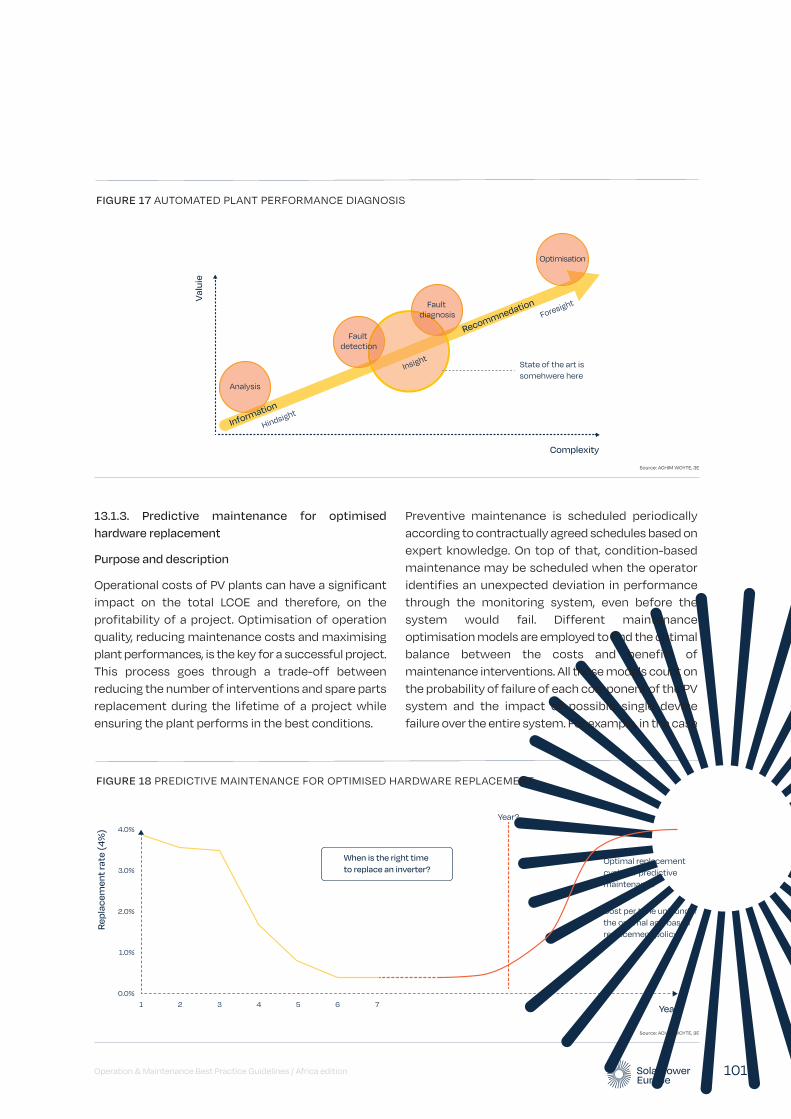
13.1.3. Predictive maintenance for optimised hardware replacement
Purpose and description
Operational costs of PV plants can have a significant impact on the total LCOE and therefore, on the profitability of a project. Optimisation of operation quality, reducing maintenance costs and maximising plant performances, is the key for a successful project. This process goes through a trade-off between reducing the number of interventions and spare parts replacement during the lifetime of a project while ensuring the plant performs in the best conditions.
Preventive maintenance is scheduled periodically according to contractually agreed schedules based on expert knowledge. On top of that, condition-based maintenance may be scheduled when the operator identifies an unexpected deviation in performance through the monitoring system, even before the system would fail. Different maintenance optimisation models are employed to find the optimal balance between the costs and benefits of maintenance interventions. All those models count on the probability of failure of each component of the PV system and the impact of possible single device failure over the entire system. For example, in the case
Operation & Maintenance Best Practice Guidelines / Africa edition 101
FIGURE 17 AUTOMATED PLANT PERFORMANCE DIAGNOSIS
Complexity
State of the art is somehwere here
Information
Recommnedation
Va
luie
mat
Analysis
Insight
Hindsight
Foresight
Fault detection
Fault diagnosis
Optimisation
Source: ACHIM WOYTE, 3E
FIGURE 18 PREDICTIVE MAINTENANCE FOR OPTIMISED HARDWARE REPLACEMENT
Year
Optimal replacementcycle for predictivemaintenance
Re
pla
ce
me
nt r
ate
(4
%) 4.0%
3.0%
2.0%
1.0%
0.0%1 2 3 4 5 6 7
Cost per time unit under the optimal age-basedreplacement policy
Year?
When is the right time
to replace an inverter?
Source: ACHIM WOYTE, 3E
of PV inverters, it is still uncertain what their actual lifetime will be under site specific operating conditions. In practice, inverters will not fail at a precise given moment in time as often modelled in the business plan. Moreover, failure-based maintenance i.e. replacing the inverter(s) when this fails may not be the most efficient solution.
A good predictive monitoring system could help on assessing the optimal hardware replacement cycle by modelling the uncertainty in the time-to-failure with a known probability distribution function. Maintenance optimisation models can provide tools relying on the output from root cause analyses, remaining useful life time analyses and alerting and prediction of assets failures in the optimal planning of maintenance and related resource allocation.
Big data analytics can bring added value at any stage of O&M objectives: analysis from observation of collected information to fault detection, fault diagnosis and finally optimisation through recommendations issued from the advanced monitoring system. Today different approaches are proposed. Whereas classic Artificial Intelligence (AI) proposes an advanced diagnostic through knowledge-based models, unsupervised and supervised learnings methods offer different approaches (e.g. neural networks) using statistical approaches.
Advantages and disadvantages
Advantages:
• Lowering the cost of ineffective scheduled maintenance
• Reducing device downtime
Disadvantage:
• Methods are often very sensitive to device models and brands and can thus not be generalised easily.
State of play
Today, no model has been proven to be completely reliable. Big-data analysis allows easy recognition of a fault and, in some cases, provides a clear diagnosis and recommendations on the short-term actions to take to avoid probable upcoming issues. The trend is to model the behaviour of the entire system and to plan optimal maintenance and hardware replacement
programs in the medium to long term. This will of course reduce the overall risk of a PV project and hence increase the investing opportunities.
13.1.4. PV plant yield forecasting
Purpose and description
Electricity generation from PV plants is limited by the varying availability of the sun’s radiation. Even though grid operators are generally obliged to dispatch PV plant production at all times, the growing penetration of PV may force new regulations to guarantee grid stability and the correct balancing of electricity supply and consumption at all times, causing unpredictable losses to plant owners (curtailment).
Ramp-rate control with and without local storage is currently studied in order to mitigate the impact of fast irradiance fluctuations on power system stability. Approached from the generator side, large PV plants could also contribute to power system stability by providing upward or downward reserves. Technically, this is possible; however, particularly the provision of upward reserves will reduce the overall performance of the plant in question. The business case for such operation modes will depend on the incentives available for deviating from the objective of maximum energy yield.
State of play
The prediction of PV production is becoming an essential tool to capture economies in a market with large penetration of variable renewable energy sources. Expected PV yield output accounting for specific PV plant simulation model and forecasted meteorological resource is a well proven technology. Algorithms that are able to match weather forecasts with PV plant characteristics in order to predict energy production on an hourly basis for few hours ahead and up to the next 48 hours are already playing an important role in the monitoring software market.
The market is rapidly moving towards the need of advanced intra-day correction of the forecasted energy production at sub-hourly resolution and by taking into account actual PV plant conditions like remote curtailment, broken inverters, local losses, etc. Therefore, long and short-term data collection constitute an added value to improve the PV plant yield forecasting.
13 Innovations and trends / continued
Operation & Maintenance Best Practice Guidelines / Africa edition 102

A clear communication protocol between devices in the field (sensors, modules, inverter, loggers, etc.) would help to improve the intra-day forecasting and better exchange with the energy grid. A comprehensive exchange of information between the devices can be used by the simulation model to compute performance expectations. This can be achieved by a trained machine learning system where the operator can set, review and validate specific conditions. In this frame, a proper standardization of terminology and languages used by any communicating device onsite is crucial. The topic of Internet of Things and its application to PV is addressed in the following Section 13.1.5.
13.1.5. Internet of Things (IoT) and auto-configuration
Purpose and description
Solar monitoring, being a crucial function in the asset operations, is often still a painful and costly process: failing or unstable local hardware, failing communication between the local devices, failing communication with the cloud or data centre infrastructure, configuration issues in loggers or in the portal, high costs for communication, configuration or reporting.
Additionally, requirements with respect to the interaction of the solar power plants with the grid and the electricity markets, increase and put new specifications on the speed, the protocols and the security levels applied.
Internet of Things (IoT) in photovoltaic systems represents an interoperability environment where all devices in the field are connected to each other and spontaneously show themselves as available to be connected to the system. Additionally, each connecting device should provide the following information:
• Device parameters (brand, type, Serial Number, internal datasheet specifications)
• Device status and conditions (operational status, temperature, etc.)
• Connection with other devices & mapping (strings connected, inverter, sensor position, etc.)
• Any other relevant information
Standardisation efforts (e.g. SunSpec Alliance’s Orange Button initiative) are taking place throughout the PV market and will help to improve on configuration costs for solar monitoring. However, the solar monitoring industry will also benefit heavily from the emerging Internet-of-things technologies that further improve plug-and-play behaviour of device communication, improve the quality and the security of the communication and reduce the cost of hardware.
Advantages and disadvantages
Advantages
• Reduce the cost of monitoring hardware and infrastructure.
• Reduce the cost of configuration and maintenance of the monitoring infrastructure.
• Improve the quality and the stability of the data.
• Improve the security level and the options for bidirectional communication.
Disadvantages
• Existing hardware and monitoring equipment will not be necessarily compatible with the new Internet-of-Things technologies resulting in hybrid solutions until the former technologies are phased out.
State of play
Many Internet-of-Things (IoT) technologies have passed the prototype phase and are available for massive deployment. However many different technological solutions and approaches are still available in the market and no final best-practice approach has emerged.
Again, this leads to a standardisation issue for industry-wide adoption of Internet-of-Things technology within the solar industry and as such benefits from its advantages will be reduced when considering PV on a larger scale.
Operation & Maintenance Best Practice Guidelines / Africa edition 103
13.1.6. Future best practices in document management systems
Purpose and description
Asset contractual and technical documentation as described in today’s Best Practices can be handled either physically or electronically, as far as the employed Document Management System (DMS) keeps all documents ready consultation by or transfer to relevant stakeholders. The inventory of technical documentation linked to a portfolio of plants can become very complex, especially in an era where the solar sector is moving towards a secondary market. Considering the number of documents to be stored and exchanged per plant, the increasing number of stakeholders that should have free access to a subset or the totality of the documentation, the physical exchange and storage of files becomes nearly impossible to be maintained without a proper quality process. Electronic document management and storage is thus becoming a best practice within the Solar industry.
At the same time, the use of meta-tags instead of a classical tree structure is a technique of filing that is becoming more widespread where asset documentation can be considered as relevant to different stakeholders or belonging to different portfolios. The use of meta-information and their standardisation under a common nomenclature is seen as the next best practice, especially to facilitate the contractual management of big portfolios and the maintenance operations.
Next to meta-tagging documents with additional information, making any document (scan, word, xls, mail, etc.) full text searchable adds to the best practices to make sure that all information can be listed and searched for when the need occurs.
Both technical and contractual documentations, including device replacement, scheduled maintenances, operators contacts, calendar of operations, intervention reports, should be tagged and electronically stored using a standardised terminology. This will facilitate their retrieval and updates as well as operation management or transition of a plant to a new O&M contractor.
Additionally, the selected DMS should allow a suitable user management system that will automatise the exchange and security of sensitive documents between stakeholders.
Advantages and disadvantages
The idea of meta-tagging documentation allows any document to be tagged with different criteria. This way any piece of information can be stored over multiple time areas, assets, records or any relevant criterium. The-meta tagging allows the user or the applications to filter information on relevant criteria only. For example, only pictures from a certain period, or only plans from a defined equipment type. This way of meta tagging also avoids the need for documents to be copied or stored in multiple locations.
State of play
In terms of technological readiness and market uptake, digital DMS solutions using meta-tags and full-text search are already existing and adopted by some Asset Managers and O&M contractors. This technology could become soon a best practice, though the standardisation of document tagging in the solar industry is not yet implemented.
Document recognition and meta-tag auto-filling is already available on most documents including some scanned file types via OCR (Optical Character Recognition). At a next level, image recognition and auto-tagging would save operational time.
13.2. Retrofit coatings for PV modules
13.2.1. Anti-soiling coatings
Purpose and description
Solar cells, just like human eyes, need a clean field to function properly. Deposits and particles covering the surface of PV panels, like soiling, staining, dirt and grime, leaves, pollen, bird droppings, lime-scale and other environmental or industrial pollutants, prevent solar radiation from reaching the cells of PV modules and inevitably the efficiency and the optimal function of the solar system is reduced.
Soiling influences the levelised cost of electricity (LCOE) in two ways: by leading to an O&M cost (periodic cleaning), and by reducing the energy produced from 1%-10% in normal cases and up to 80% in extreme situations. In general, the presence of dirt or any other particles on the module surface has an impact on the anti-soiling properties; specific coating products with anti-soiling properties which also
13 Innovations and trends / continued
Operation & Maintenance Best Practice Guidelines / Africa edition 104

provide anti-reflective performances have been developed in the last years.
Advantages and disadvantages
Modules treated with anti-soiling coatings get dirty less quickly and are easier to clean and therefore maintain higher performance levels for longer, reducing the amount of module cleaning necessary and increasing yield by up to 3%. This is particularly interesting in arid regions, as anti-soiling coatings can help to reduce water use for PV module cleaning.
Some anti-soiling coatings can also be used to restore corroded PV module surfaces. Most anti-soiling coatings are relatively easy to use so that they can be applied by the O&M Contractor.
When it comes to applying coatings to already installed modules in general, the O&M Contractor should carefully evaluate possible consequences for PV module warranties and for any incentive or tariff schemes.
Retrofit anti-soiling coatings are a layer applied on the surface of the modules that in principle do not affect the properties of the glass surface and that can be removed if needed for warranty purposes.
State of play
There are already various commercially available anti-soiling coatings that can be applied on PV modules that have already been installed. New solutions are also being developed – some of which outperform older anti-soiling coatings or even anti-reflective coatings in terms of power gain. The new generation of retrofit anti-soiling coatings are mostly based on spray technologies but some anti-soiling coating suppliers are developing specific solutions for desertic areas that are applied via mechanical systems.
13.2.2. Anti-reflective coatings
Purpose and description
Reflection losses are one of the first loss factors occurring in the energy flow when converting sunlight to electricity via the PV power plant.
New anti-reflective coatings (ARC) that can be applied directly via a ‘retrofit’ method onto PV modules
already installed in the field. Applied to the surface of the panels, these coatings reduce the reflection and thereby the losses due to reflection resulting in a higher energy output.
Innovative new coatings specifically engineered for aftermarket application are based on the same technology platform as the leading anti-reflective technology for new modules. These coatings reduce the amount of light reflected off the glass, allowing more light to travel through to the solar cell and to be converted into electricity.
An ARC works by providing an incoming photon with a very gradual transition from air to glass. It does this by varying the porosity of the material from very high at the coating-air interface to very low at the coating-glass interface. An ARC layer has typically a thickness of 120-150nm and can be applied on the module surface through special equipment, commonly named “applicator”, or via spray. Both technologies provide different results in terms of layer uniformity, thickness and performance. The more controllable is the coating process the better will be the final result.
ARC is based on a silica-gel solution that is applied on the module surface. Once applied, the solution become a solid layer after a period of curing. Tests executed with mechanical application show power gain in the range of 3%-5%. An additional point to be considered when it comes to ARC retrofit technology is the durability of the coating layer. A good ARC should last for at least 5 years with a physiological yearly degradation that shouldn’t reduce the coating properties more than 30% from its original performance.
Advantages and disadvantages
Retrofit anti-reflective coatings can increase module output in the field by up to 3-4%. In some cases, pilot tests have shown energy gains up to 5%.
When it comes to applying coatings to already installed modules in general, the O&M Contractor should carefully evaluate possible consequences for PV module warranties and for any incentive or tariff schemes. An ARC, if applied properly through a mechanical application specifically developed for the purpose, does not damage the module surface. A new generation of modules has an ARC applied during the manufacturing process. A coating supplier that performs ARC properly
Operation & Maintenance Best Practice Guidelines / Africa edition 105
should be able to provide the client specific warranties (e.g. product liability insurance).
State of play
There are already commercially available anti-reflective coatings that can be applied in a retrofit manner. Other products are currently being developed and tested to substantiate the applicability of the solution on a large scale and data will be collected from different locations.
“Mature” ARC technologies which has been tested for years are already available. They provide reliable results both in terms of durability and overperformance. This coating solution is based on a mechanical application via a controlled process that involves pre-coating measurements, quality control during the coating process and post-coating measurements. For this purpose, sophisticated equipment such as spectrometers, able to measure the variation (%) of reflection before and after the coating process, are needed. The market provides a wide offer of such devices and with prices in the range of 5-9k EUR, but not all spectrometers are good for ARC applications.
13.3. Waterless cleaning of PV modules
In many places around the globe which receive significant precipitation at least once a month, the need to wash solar panels is almost irrelevant. A study published in the International Journal of Sustainable Energy found that one gram of dirt per square meter can decrease a panel’s output by more than 30 percent, which is why commercial PV farms often employ some form of cleaning (Al-hasan & Ghoneim, 2007).
However, many utility-scale and commercial and industrial PV sites in Africa are located in arid climates. These arid regions are known for large amounts of dust and insufficient rainfall to automatically clean solar panels. Furthermore, in some of these regions, access to clean water is a problem which further exacerbates the problem of cleaning solar modules.
Various solutions have been launched over the past few years including nano-coating the glass on solar modules installed in arid areas (see also section 13.2.1. on Anti-soiling coatings), the use of pneumatic cleaning systems which employs pressurised air jets and robots which use a combination of brushes and air blowers to remove dust, sand and bird droppings from modules without using water.
Further research in this field is ongoing in multiple facilities globally and it is expected that the outcome of this research will result in ever-better solutions and PV yield performance as these solutions are commercialised.
13 Innovations and trends / continued
Operation & Maintenance Best Practice Guidelines / Africa edition 106

Operation & Maintenance Best Practice Guidelines / Africa edition 107
O&M for standalone solar installations with storage
14© Shutterstock
In 2017, about 850 million people in the world remained without access to electricity, and about 70% of those people live in Sub-Saharan Africa (ARE, 2019; ESMAP, 2019). Due to dramatical cost reductions for solar-battery-based systems, it is expected that most new mini-grids will be based at least partially on solar. Therefore, standalone PV plants and mini-grids are very important for electrification of off-grid areas in Sub-Saharan Africa.
Operation of mini-grids is probably one of the most complex matters of PV, because it depends on many variables like composition of the generator, local distribution of consumers, consumption profile, strategy for later integration into a centralized grid etc. For this reason, are limiting our first approach to O&M of PV plants in off-grid areas to standalone systems – with or without Energy Storage Systems (ESS).
In consequence, this chapter is to assist in the application of the best practices, detailed in the previous chapters of the document, to off-grid PV plants. All best practices mentioned in these Guidelines could be theoretically applied to off-grid systems, however in the case of off-grid systems there will be different priorities. Apart from providing the highest possible care in the most cost-efficient manner to deliver the lowest levelized cost of electricity (LCOE), other objectives are at least as important, such as:
• Availability of electricity at the moment of demand and ease of maintenance;
• Availability of professional knowledge: expertise is not always available;
• Local instead of central monitoring.
Standalone solar PV systems are often combined with Energy Storage Systems (ESS). ESS are a set of technologies whose aim is to decouple energy generation from demand. The systems allow for excess electricity to be “stored” and released during periods of high electricity demand, providing cost-saving opportunities to consumers and ensuring a steady and safe electricity supply. Energy storage can contribute to better use of renewable energy in the electricity system since it can store energy produced when the conditions for renewable energy are good, but demand may be low.
The selection of a storage system can significantly influence a project’s overall O&M strategy. Technical parameters such as battery lifetime, efficiency, depth of discharge (DoD) and/or power density, should be taken into consideration at the development stage to select the adequate ESS and avoid unnecessary costs throughout the project’s lifecycle.
14.1. Environment, Healthy & Safety
Necessary precautions as outlined in Chapter 3. Environment, Health & Safety should be taken for standalone solar PV systems. Further emphasis should be placed on training and skills required for working in heights and on roofs. It is more likely that access to the system is available to other parties not directly involved in the upkeep of the solar system. Installers and O&M providers should provide “stakeholder training” for people working or living in the proximity of the installation.
Proper signalization of dangers should be displayed beside any hazardous device.

It is best practice to design the system in a way that allows straightforward removal and replacement of modules. The system itself should be easily accessible for inspection without needing to significantly disassemble the ESS system. Disposal of hazardous material should comply with local and national rules and regulations.
When dealing with owners of off-grid standalone systems, who are usually not professional solar stakeholders, additional thought must be given to the information provided to them at all stages of project lifecycle.
• Retailers/installers should be clear about the need for ongoing maintenance and make sure this is reflected in any financial analysis provided to customers. Best practice would involve either
• The retailer providing maintenance service themselves (or)
• Ensuring a clear and continuous handover to 3rd party O&M.
• Provide a manual to the homeowner with contact information and description of operational indicators and procedures they can do, including clear documentation that states the customer as responsible for maintaining original insolation/shade.
14.2. Monitoring & reporting
In the case of standalone systems, the Asset Owner is typically not a solar professional, therefore reporting needs to be easily understood and clear. The purpose of reporting is to verify the asset is performing in accordance to expectations as promised by the retailer/installer in the selling process.
A central question is to ensure the accuracy of the performance monitoring of a standalone PV system, given the likely absence of a pyranometer and module temperature sensors.
Key Performance Indicators
For reporting to Asset Owners, emphasis shall be placed on the Energy Performance Index (EPI) rather than Availability, Downtime or Performance Ratio. EPI is an easily explainable metric that does not require an in depth understanding of solar. (See 11.1.2.6. Energy Performance Index for more details)
Operation & Maintenance Best Practice Guidelines / Africa edition 108
EH&S considerations for Energy Storage Systems
Most batteries are subject to environmental regulations that require recycling or proper disposal at end of performance period. The ESS mentioned above are electrical appliances and as such are subject to significant health & safety risks. To prevent hazards (e.g. uncontrolled release of energy), an appropriate risk assessment must be performed during the design and planning phases and necessary safety precautions implemented. The hazards must be identified during these stages and appropriate measures taken to mitigate risk and to protect those operating the system. The main risks are: impact, excessive heat, crush or water penetration and electrical shock There is also a significant health and safety risk of poisoning or mishandling hazardous materials, especially the sulphuric acid electrolyte added to lead-acid batteries.
Both external and internal factors should be considered during the risk assessment since, in some cases, the ESS itself can be the cause of hazardous event. The major hazards for large-scale ESS can be categorised as follows:
• Electrical, occurring when there is direct contact between a person and the system
• Mechanical, occurring after a physical collision
• Poisoning or exposure to hazardous materials
• Other, occurring due to an explosion, fire, thermal runaway, or the leaking of chemical components from the system.
To avoid risks, the system should not overheat, come into contact with water, or suffer from either electrical stress or high humidity. The risk of electrical shock can be mitigated - as is common practice in photovoltaic plants - with appropriate electrical insulation: for instance, by wearing appropriate personal protective equipment (PPE). The energy storage system should be maintained by trained technicians since improper handing increases the risk of electrical shock. For personnel qualifications during the installation and maintenance of stationary batteries, reference should be made to IEEE 1657 - 2018.
Safety data sheets should be provided to those operating the system. In case of repair or replacement, addition or alteration of the system, the safety system should be re-evaluated and, if necessary, additional safety systems implemented.
14 O&M for standalone solar installations with storage / continued
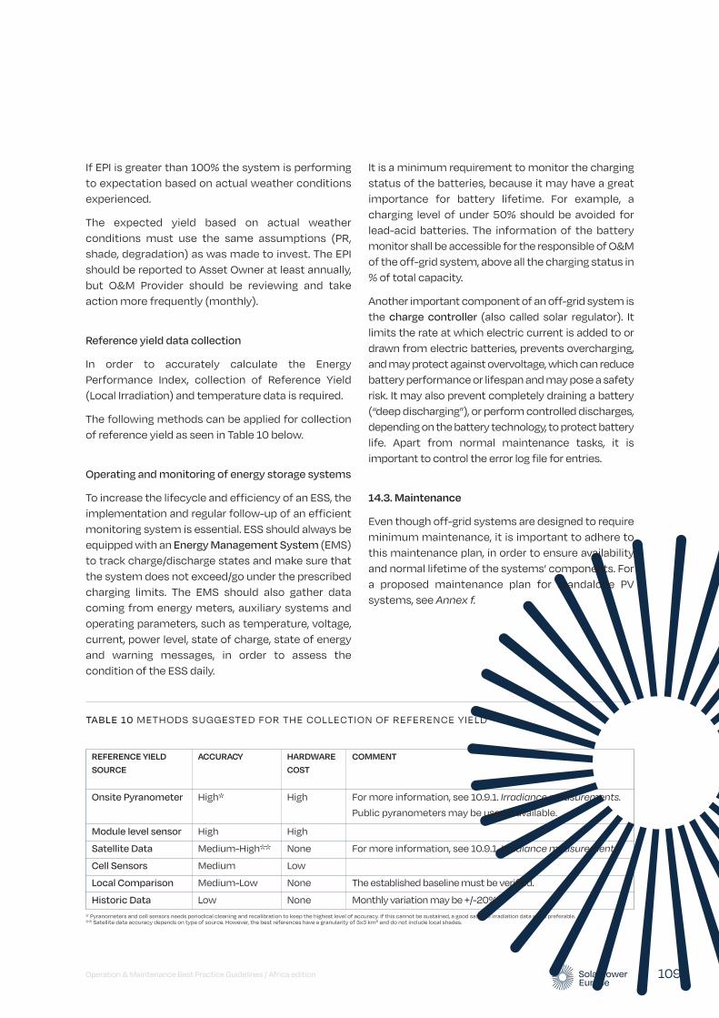
Operation & Maintenance Best Practice Guidelines / Africa edition 109
It is a minimum requirement to monitor the charging status of the batteries, because it may have a great importance for battery lifetime. For example, a charging level of under 50% should be avoided for lead-acid batteries. The information of the battery monitor shall be accessible for the responsible of O&M of the off-grid system, above all the charging status in % of total capacity.
Another important component of an off-grid system is the charge controller (also called solar regulator). It limits the rate at which electric current is added to or drawn from electric batteries, prevents overcharging, and may protect against overvoltage, which can reduce battery performance or lifespan and may pose a safety risk. It may also prevent completely draining a battery (“deep discharging”), or perform controlled discharges, depending on the battery technology, to protect battery life. Apart from normal maintenance tasks, it is important to control the error log file for entries.
14.3. Maintenance
Even though off-grid systems are designed to require minimum maintenance, it is important to adhere to this maintenance plan, in order to ensure availability and normal lifetime of the systems’ components. For a proposed maintenance plan for standalone PV systems, see Annex f.
If EPI is greater than 100% the system is performing to expectation based on actual weather conditions experienced.
The expected yield based on actual weather conditions must use the same assumptions (PR, shade, degradation) as was made to invest. The EPI should be reported to Asset Owner at least annually, but O&M Provider should be reviewing and take action more frequently (monthly).
Reference yield data collection
In order to accurately calculate the Energy Performance Index, collection of Reference Yield (Local Irradiation) and temperature data is required.
The following methods can be applied for collection of reference yield as seen in Table 10 below.
Operating and monitoring of energy storage systems
To increase the lifecycle and efficiency of an ESS, the implementation and regular follow-up of an efficient monitoring system is essential. ESS should always be equipped with an Energy Management System (EMS) to track charge/discharge states and make sure that the system does not exceed/go under the prescribed charging limits. The EMS should also gather data coming from energy meters, auxiliary systems and operating parameters, such as temperature, voltage, current, power level, state of charge, state of energy and warning messages, in order to assess the condition of the ESS daily.
REFERENCE YIELD SOURCE
ACCURACY HARDWARE COST
COMMENT
Onsite Pyranometer High* High For more information, see 10.9.1. Irradiance measurements.
Public pyranometers may be used if available.
Module level sensor High High
Satellite Data Medium-High** None For more information, see 10.9.1. Irradiance measurements.
Cell Sensors Medium Low
Local Comparison Medium-Low None The established baseline must be verified.
Historic Data Low None Monthly variation may be +/-20%.
TABLE 10 METHODS SUGGESTED FOR THE COLLECTION OF REFERENCE YIELD
* Pyranometers and cell sensors needs periodical cleaning and recalibration to keep the highest level of accuracy. If this cannot be sustained, a good satellite irradiation data set is preferable. ** Satellite data accuracy depends on type of source. However, the best references have a granularity of 3x3 km² and do not include local shades.
14 O&M for standalone solar installations with storage / continued
Operation & Maintenance Best Practice Guidelines / Africa edition 110
Maintenance of energy storage systems
The most critical parts of off-grid systems are the batteries (or ESS). There are two types of batteries:
• Wet cell batteries (or flooded cell batteries)
• Dry cell batteries
The wet cell batteries used in off-grid PV systems are normally vented lead acid batteries (VLA batteries). In principle thick lead-based plates that are flooded with an acid electrolyte. The container is unsealed (“vented”), because gases produced during operation need to escape to the air. Therefore, the batteries have to be kept upright and the area be well ventilated to ensure safe dispersal of the hydrogen gas it produces during overcharging. Normally they are kept in dedicated battery rooms, and strict safety measures have to be observed. VLA batteries are highly reliable, if maintenance instructions are observed (for example, adding water in order to regenerate the electrolyte liquid). However, flexibility is limited, because after some months it will be difficult to add new batteries to an existing system. It is important to use VLA batteries for solar application. VLA batteries for cars or motorcycles are inappropriate and will break down quickly.
A dry cell battery uses a paste electrolyte, with only enough moisture to allow current to flow. Therefore, it can operate in any orientation without spilling. Valve-regulated lead-acid batteries (VRLA batteries; sealed lead-acid batteries, captive electrolyte lead-acid batteries) are lead batteries with immobilized sulfuric acid electrolyte. Since they are sealed within polypropylene plastic and hydrogen recombines with oxygen inside the battery, water or gases do not escape under normal conditions, and water needs not to be added. For this reason, they are also called ‘maintenance-free’ batteries, even if this term is misleading, because it only refers to water refilling. They are ‘valve-regulated’, because security valves will vent the batteries, when gas pressure becomes too great inside the battery, for example because of excessive overcharging.
Two common types of VRLA batteries used in PV systems are:
• Gel batteries, which use a silicon dioxide gel as electrolyte.
• Absorbed Glass Mat (AGM) batteries, where a fiberglass mats absorb the electrolyte.
In the last years another type of dry cell battery has spread rapidly: lithium-ion batteries (LIB). They combine high power density (small size), high cycle-count (number of charge-discharge cycles during lifetime), and fast recharge times. They may also operate at higher ambient temperatures as compared to lead-acid batteries. Furthermore, a LIB pack normally includes a battery management system, which facilitates battery handling. They are (still) more expensive than lead-acid batteries, but prices are decreasing rapidly.
Apart from battery typology, three factors determine battery lifetime:
1. Ambient temperature
2. Cycling
3. Quality of maintenance
The rated capacity of a battery is based on an ambient temperature of 25°C. Any variation from this operating temperature can alter the battery’s performance and shorten its expected life. Depending on the type of battery, this factor may be more or less important.
Each cycle (discharge and subsequent recharge) reduces the battery’s relative capacity by a small percentage, albeit a much smaller percentage for LIB. The length and depth of the discharge cycle determines the reduction in battery capacity.
Gradual decrease in battery life can be monitored and evaluated through voltage checks, load testing or monitoring. Periodic preventive maintenance extends battery string life by preventing loose connections, removing corrosion and identifying bad batteries before they can affect the rest of the string. By respecting the manufacturer’s maintenance guidelines, the end of battery life can be accurately estimated and replacements scheduled without unexpected downtime.
In order to perform a systematics maintenance, a plan on location showing how component and system must be tested is required. In case of reparation or replacement or of any component within the system, it should be checked whether the change comply with the applicable regulation.
14 Note: this list is intended to be illustrative and not limiting.
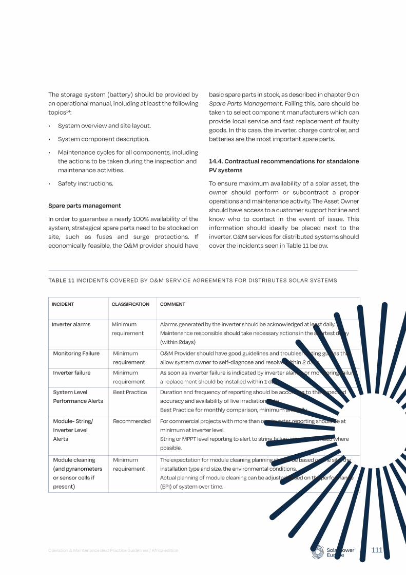
Operation & Maintenance Best Practice Guidelines / Africa edition 111
The storage system (battery) should be provided by an operational manual, including at least the following topics14:
• System overview and site layout.
• System component description.
• Maintenance cycles for all components, including the actions to be taken during the inspection and maintenance activities.
• Safety instructions.
Spare parts management
In order to guarantee a nearly 100% availability of the system, strategical spare parts need to be stocked on site, such as fuses and surge protections. If economically feasible, the O&M provider should have
basic spare parts in stock, as described in chapter 9 on Spare Parts Management. Failing this, care should be taken to select component manufacturers which can provide local service and fast replacement of faulty goods. In this case, the inverter, charge controller, and batteries are the most important spare parts.
14.4. Contractual recommendations for standalone PV systems
To ensure maximum availability of a solar asset, the owner should perform or subcontract a proper operations and maintenance activity. The Asset Owner should have access to a customer support hotline and know who to contact in the event of issue. This information should ideally be placed next to the inverter. O&M services for distributed systems should cover the incidents seen in Table 11 below.
INCIDENT CLASSIFICATION COMMENT
Inverter alarms Minimum
requirement
Alarms generated by the inverter should be acknowledged at least daily.
Maintenance responsible should take necessary actions in the shortest delay
(within 2days)
Monitoring Failure Minimum
requirement
O&M Provider should have good guidelines and troubleshooting guides that
allow system owner to self-diagnose and resolve within 2 days.
Inverter failure Minimum
requirement
As soon as inverter failure is indicated by inverter alarms or monitoring failure
a replacement should be installed within 1 day.
System Level
Performance Alerts
Best Practice Duration and frequency of reporting should be according to the expected
accuracy and availability of live irradiation data.
Best Practice for monthly comparison, minimum annually.
Module- String/
Inverter Level
Alerts
Recommended For commercial projects with more than one inverter, reporting should be at
minimum at inverter level.
String or MPPT level reporting to alert to string failure is recommended where
possible.
Module cleaning
(and pyranometers
or sensor cells if
present)
Minimum
requirement
The expectation for module cleaning planning should be based on the site, the
installation type and size, the environmental conditions.
Actual planning of module cleaning can be adjusted based on the performance
(EPI) of system over time.
TABLE 11 INCIDENTS COVERED BY O&M SERVICE AGREEMENTS FOR DISTRIBUTES SOLAR SYSTEMS

Al-hasan, Ahmad Y. & Ghoneim, Adel A. (2007), “A new correlation between photovoltaic panel's efficiency and amount of sand dust accumulated on their surface”, in: International Journal of Sustainable Energy, Web: https://www.tandfonline.com/doi/abs/10.1080/14786450500291834
ARE (Alliance for Rural Electrification) (2019), Annual Report 2019, Web: https://www.ruralelec.org/publications/annual-report-2019
Brabandere, K. De; M. Richter; F. Assiandi and B. Sarr. 2014. “Engineering Models for PV System Operations,” Performance Plus WP2 Deliverable D2.3, Jul. 2014.
Eder G.C., Y. Voronko, P. Grillberger, B. Kubicek, K. Knöbl, “UV-Fluorescence Measurements as Tool for the Detection of Degradation Effects in PV-Modules”, 34th EUPVSEC 2017.
ESMAP (Energy Sector Management Assistance Program) (2019), Mini Grids for Half a Billion People: Market Outlook and Handbook for Decision Makers, Web: https://www.esmap.org/new_esmap_report_minigrids_for_half_a_billion_people
European Commission. 2018. “Energy storage”. Web: https://ec.europa.eu/energy/en/topics/technology-and-innovation/energy-storage
European Commission. 2019. “Cybersecurity Act”. Web: https://ec.europa.eu/digital-single-market/en/news/cybersecurity-act-strengthens-europes-cybersecurity
European Parliament. 2016. Cyber Security Strategy for the Energy Sector (IP/A/ITRE/2016-04 PE587.333. Web: http://www.europarl.europa.eu/RegData/etudes/STUD/2016/587333/IPOL_STU(2016)587333_EN.pdf
GTM. 2013. “Megawatt-Scale PV Plant Operations and Maintenance: Services, Markets and Competitors, 2013-2017”, Greentech Media.
IEC 61724-1:2017. Photovoltaic system performance - Part 1: Monitoring. International Electrical Commission. Web: https://webstore.iec.ch/publication/33622
IEC TS 62446-3 Ed.1: Photovoltaic (PV) systems - Requirements for testing, documentation and maintenance - Part 3: Photovoltaic modules and plants - Outdoor infrared thermography.” 2017.
ISO 9060. 2018. “Solar energy — Specification and classification of instruments for measuring hemispherical solar and direct solar radiation.” Web: https://www.iso.org/standard/67464.html
J. Ulrike, M. Herz, M. Köntges, D. Parlevliet, M. Paggi, I. Tsanakas, J.S. Stein, K. A. Berger, S. Ranta, R. H. French, M. Richter, T. Tanahashi, Review on Infrared and Electroluminescence Imaging for PV Field Applications, Report IEA-PVPS T13-10:2018, ISBN 978-3-906042-53-4, Web: http://iea-pvps.org/index.php?id=480
KIC InnoEnergy. 2015. “Future renewable energy costs: solar photovoltaics. How technology innovation is anticipated to reduce the cost of energy from European photovoltaic installations”. Web: http://www.innoenergy.com/wp-content/uploads/2016/01/KIC-InnoEnergy-Solar-PV-anticipated-innovations-impact.pdf
Klise, G. T. and J. S. Stein. 2009. “Models Used to Assess the Performance of Photovoltaic Systems,” Sandia National Laboratories, SAND2009-8258, Dec. 2009.
Köntges M., S. Kajari-Schröder, I. Kunze, “Cell Cracks Measured by UV Fluorescence in the Field”, 27th EUPVSEC 2012.
Lausch D., M. Patzold, M. Rudolph, C.-M. Lin, J, Froebel, K. Kaufmann, “Magnetic Field Imaging (MFI) of Solar Modules”, 35th EUPVSEC 2018.
Muehleisen W., G. C. Eder, Y. Voronko, M. Spielberger, H. Sonnleitner d, K. Knoebl, R. Ebner, G. Ujvari, Chr. Hirschl, “Outdoor detection and visualization of hailstorm damages of photovoltaic plants”, Renewable Energy 118 (2018) 138-145.
NREL. 2017. System Advisor Model (SAM). National Renewable Energy Laboratory. http://sam.nrel.gov.
NREL, 2018. Best Practices for Operation and Maintenance of Photovoltaic and Energy Storage Systems, 3rd Edition. National Renewable Energy Laboratory, Sandia National Laboratory, SunSpec Alliance and the SunShot National Laboratory Multiyear Partnership (SuNLaMP) PV O&M Best Practices Working Group; December 2018, Web: https://www.nrel.gov/docs/fy19osti/73822.pdf
N. Reich, B. Mueller, A. Armbruster, W. G. J. H. M. van Sark, K. Kiefer, and C. Reise. 2012. “Performance Ratio Revisited: Is PR > 90% Realistic?” Progress in Photovoltaics: Research and Applications 20 (6): 717–26. doi:10.1002/pip.1219.
Patzold M., K. Kaufmann, C.-M. Lin, M. Rudolph, D. Lausch, “Quantitative Evaluation Of Soldering Contacts During Thermal Cycling Using Magnetic Field Imaging (Mfi), 36th EUPVSEC 2019
Pelland, Sophie; Jan Remund; Jan Kleissl; Takashi Oozeki and Karel De Brabandere. 2013. “Photovoltaic and Solar Forecasting - State of the Art.” Report IEA PVPS T14-01:2013. International Energy Agency Photovoltaic Power Systems Programme.
PVsyst SA. 2017. PVsyst Photovoltaic Software. http://www.pvsyst.com.
Richter, Mauricio, Karel De Brabandere, John Kalisch, Thomas Schmidt, and Elke Lorenz. 2015. “Best Practice Guide on Uncertainty in PV Modelling.” Public report Performance Plus WP2 Deliverable D2.4. Web: http://www.perfplus.eu/frontend/files/userfiles/files/308991_PerfPlus_Deliverable_D2_4_20150205.pdf
SANDIA. 2017. PVPerformance Modeling Collaborative. https://pvpmc.sandia.gov/
SAS. 2018. “Data Mining, what it is and why it matters.” Web: https://www.sas.com/en_us/insights/analytics/data-mining.html. Retrieved on 19/09/2018.
Schlothauer J., S. Jungwirth, M. Köhl, B. Röder, „Degradation of the encapsulant polymer in outdoor weathered photovoltaic modules”, Solar Energy Materials & Solar Cells 102(2012) 75- 85”.
Shelton Honda, Alex Lechner, Sharath Raju, and Ivica Tolich. 2012. “Solar PV System Performance Assessment Guideline for SolarTech.” San Jose, California: San Jose State University.
SolarPower Europe (2020), Asset Management Best Practice Guidelines, Version 2.0. SolarPower Europe. Download from www.solarpowereurope.org
SolarPower Europe (2020), Engineering, Procurement and Construction (EPC) Best Practice Guidelines, Version 1.0. SolarPower Europe. Download from www.solarpowereurope.org
Woyte, Achim, Mauricio Richter, David Moser, Stefan Mau, Nils H. Reich, and Ulrike Jahn. 2013. “Monitoring of Photovoltaic Systems: Good Practices and Systematic Analysis.” In 28th EU PVSEC, 3686–94. Paris, France.
Woyte, Achim, Mauricio Richter, David Moser, Nils Reich, Mike Green, Stefan Mau, and Hans Georg Beyer. 2014. “Analytical Monitoring of Grid-Connected Photovoltaic Systems - Good Practice for Monitoring and Performance Analysis.” Report IEA-PVPS T13-03: 2014. IEA PVPS.
References
Operation & Maintenance Best Practice Guidelines / Africa edition 112

Operation & Maintenance Best Practice Guidelines / Africa edition 113
A Annex
A. Applicable international standards for solar O&M
Generic for O&M
IEC 62446-1:2016 Photovoltaic (PV) systems - Requirements for testing, documentation and maintenance - Part 1: Grid connected systems - Documentation, commissioning tests and inspection
IEC 62446-2 Photovoltaic (PV) systems - Requirements for testing, documentation and maintenance - Part 2: Grid connected (PV) systems – Maintenance of PV systems
IEC TS 63049:2017 Terrestrial photovoltaic (PV) systems – Guidelines for effective quality assurance in PV systems installation, operation and maintenance
IEC 60364-7-712:2017 Low voltage electrical installations - Part 7-712: Requirements for special installations or locations - Solar photovoltaic (PV) power supply systems
System Performance and Monitoring
IEC 61724-1:2017 Photovoltaic system performance - Part 1: Monitoring
IEC TS 61724-2:2016 Photovoltaic system performance - Part 2: Capacity evaluation method
IEC TS 61724-3:2016 Photovoltaic system performance - Part 3: Energy evaluation method
IEC TS 61724-4 Photovoltaic system performance - Part 4: Degradation rate evaluation method (not yet published as of October 2019)
IEC TS 63019:2019 Photovoltaic power systems (PVPS) – Information model for availability
ISO 9847:1992 Calibrating field pyranometers by comparison to a reference pyranometer
Specialised Technical Inspections
IEC TS 62446-3:2017 Photovoltaic (PV) systems - Requirements for testing, documentation and maintenance - Part 3: Photovoltaic modules and plants - Outdoor infrared thermography
IEC 61829:2015 Photovoltaic (PV) array - On-site measurement of current-voltage characteristics
IEC TS 60904-13:2018 Photovoltaic devices - Part 13: Electroluminescence of photovoltaic modules
Other supporting documents
IEC TS 62738:2018 Ground-mounted photovoltaic power plants - Design guidelines and recommendations
IEC TR 63149:2018 Land usage of photovoltaic (PV) farms - Mathematical models and calculation examples
IEC 60891:2009 Photovoltaic devices - Procedures for temperature and irradiance corrections to measured I-V characteristics
IEC 61853-1:2011 Photovoltaic (PV) module performance testing and energy rating - Part 1: Irradiance and temperature performance measurements and power rating
IEC 61853-2:2016 Photovoltaic (PV) module performance testing and energy rating - Part 2: Spectral responsivity, incidence angle and module operating temperature measurements
IEC 61853-3:2018 Photovoltaic (PV) module performance testing and energy rating - Part 3: Energy rating of PV modules
IEC 61853-4:2018 Photovoltaic (PV) module performance testing and energy rating - Part 4: Standard reference climatic profiles
IEC 60904-5:2011 Photovoltaic devices - Part 5: Determination of the equivalent cell temperature (ECT) of photovoltaic (PV) devices by the open-circuit voltage method
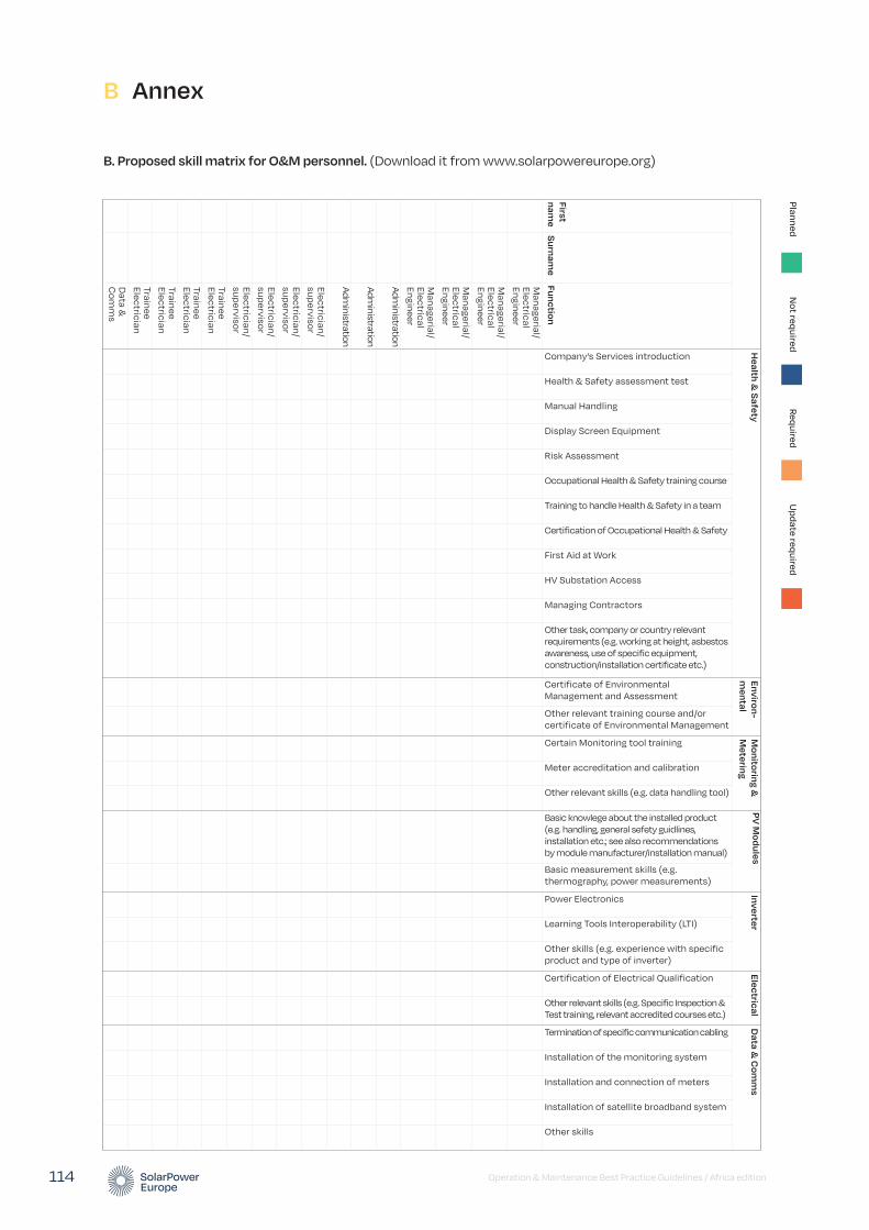
Operation & Maintenance Best Practice Guidelines / Africa edition 114
Health &
Safety
Environ-m
entalM
onitoring &
Metering
PV M
odulesInverter
ElectricalD
ata & C
omm
s
First nam
eS
urname
Function
Company’s Services introduction
Health & Safety assessment test
Manual Handling
Display Screen Equipment
Risk Assessment
Occupational Health & Safety training course
Training to handle Health & Safety in a team
Certification of Occupational Health & Safety
First Aid at Work
HV Substation Access
Managing Contractors
Other task, company or country relevant requirements (e.g. working at height, asbestos awareness, use of specific equipment, construction/installation certificate etc.)
Certificate of Environmental Management and Assessment
Other relevant training course and/or certificate of Environmental Management
Certain Monitoring tool training
Meter accreditation and calibration
Other relevant skills (e.g. data handling tool)
Basic knowlege about the installed product (e.g. handling, general sefety guidlines, installation etc.; see also recommendations by module manufacturer/installation manual)
Basic measurement skills (e.g. thermography, power measurements)
Power Electronics
Learning Tools Interoperability (LTI)
Other skills (e.g. experience with specific product and type of inverter)
Certification of Electrical Qualification
Other relevant skills (e.g. Specific Inspection & Test training, relevant accredited courses etc.)
Termination of specific communication cabling
Installation of the monitoring system
Installation and connection of meters
Installation of satellite broadband system
Other skills
Managerial/
Electrical Engineer
Managerial/
Electrical Engineer
Managerial/
Electrical Engineer
Managerial/
Electrical Engineer
Administration
Administration
Administration
Electrician/ supervisor
Electrician/ supervisor
Electrician/ supervisor
Electrician/ supervisor
Trainee Electrician
Trainee Electrician
Trainee Electrician
Trainee Electrician
Data &
C
omm
s
PlannedN
ot requiredRequired
Update required
B Annex
B. Proposed skill matrix for O&M personnel. (Download it from www.solarpowereurope.org)
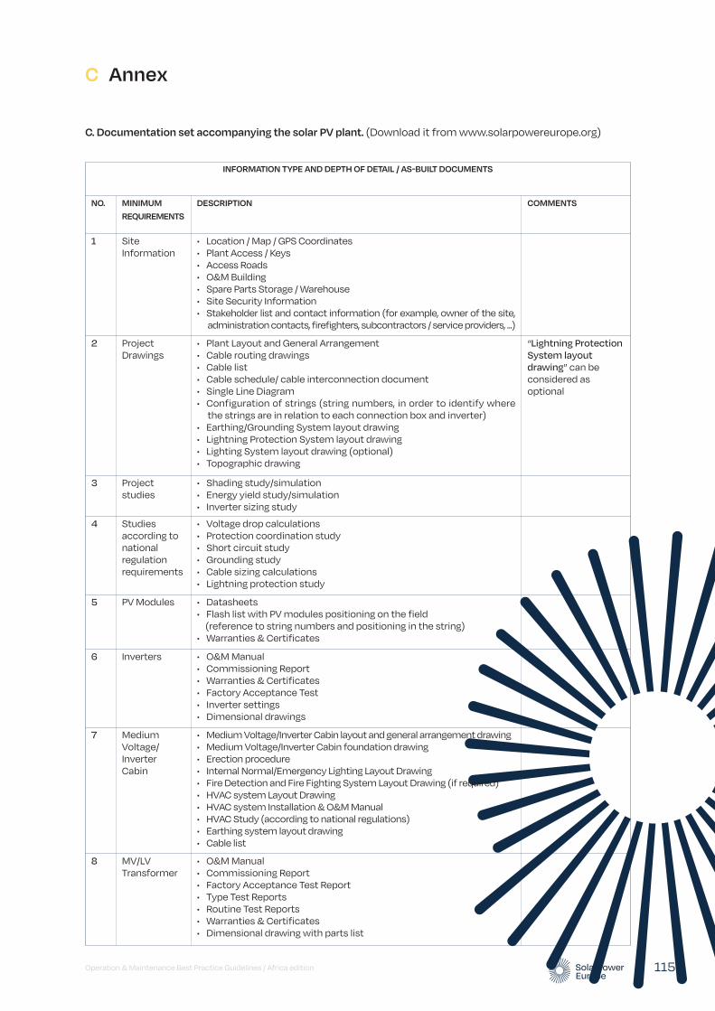
Operation & Maintenance Best Practice Guidelines / Africa edition 115
C. Documentation set accompanying the solar PV plant. (Download it from www.solarpowereurope.org)
C Annex
INFORMATION TYPE AND DEPTH OF DETAIL / AS-BUILT DOCUMENTS
NO. MINIMUM REQUIREMENTS
DESCRIPTION COMMENTS
1 Site Information
• Location / Map / GPS Coordinates • Plant Access / Keys • Access Roads • O&M Building • Spare Parts Storage / Warehouse • Site Security Information • Stakeholder list and contact information (for example, owner of the site, administration contacts, firefighters, subcontractors / service providers, ...)
2 Project Drawings
• Plant Layout and General Arrangement • Cable routing drawings • Cable list • Cable schedule/ cable interconnection document • Single Line Diagram • Configuration of strings (string numbers, in order to identify where the strings are in relation to each connection box and inverter) • Earthing/Grounding System layout drawing • Lightning Protection System layout drawing • Lighting System layout drawing (optional) • Topographic drawing
“Lightning Protection System layout drawing” can be considered as optional
3 Project studies
• Shading study/simulation • Energy yield study/simulation • Inverter sizing study
4 Studies according to national regulation requirements
• Voltage drop calculations • Protection coordination study • Short circuit study • Grounding study • Cable sizing calculations • Lightning protection study
5 PV Modules • Datasheets • Flash list with PV modules positioning on the field (reference to string numbers and positioning in the string) • Warranties & Certificates
6 Inverters • O&M Manual • Commissioning Report • Warranties & Certificates • Factory Acceptance Test • Inverter settings • Dimensional drawings
7 Medium Voltage/ Inverter Cabin
• Medium Voltage/Inverter Cabin layout and general arrangement drawing • Medium Voltage/Inverter Cabin foundation drawing • Erection procedure • Internal Normal/Emergency Lighting Layout Drawing • Fire Detection and Fire Fighting System Layout Drawing (if required) • HVAC system Layout Drawing • HVAC system Installation & O&M Manual • HVAC Study (according to national regulations) • Earthing system layout drawing • Cable list
8 MV/LV Transformer
• O&M Manual • Commissioning Report • Factory Acceptance Test Report • Type Test Reports • Routine Test Reports • Warranties & Certificates • Dimensional drawing with parts list
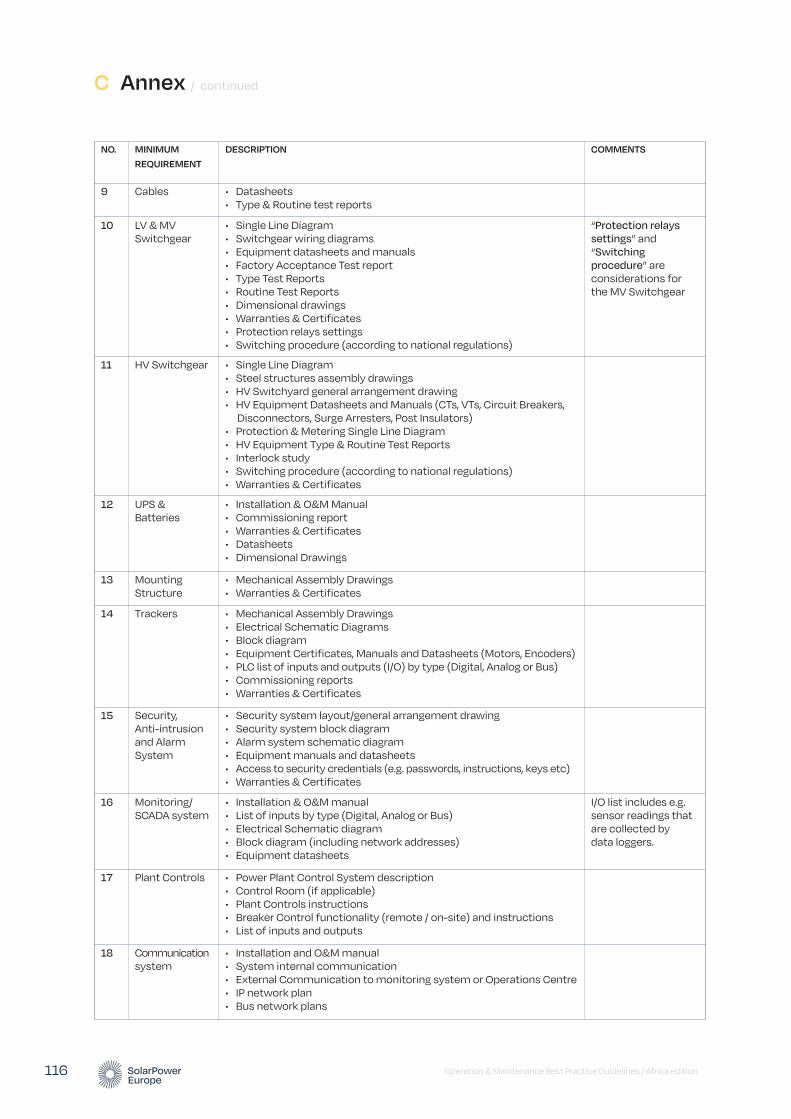
C Annex / continued
Operation & Maintenance Best Practice Guidelines / Africa edition 116
NO. MINIMUM REQUIREMENT
DESCRIPTION COMMENTS
9 Cables • Datasheets • Type & Routine test reports
10 LV & MV Switchgear
• Single Line Diagram • Switchgear wiring diagrams • Equipment datasheets and manuals • Factory Acceptance Test report • Type Test Reports • Routine Test Reports • Dimensional drawings • Warranties & Certificates • Protection relays settings • Switching procedure (according to national regulations)
“Protection relays settings” and “Switching procedure” are considerations for the MV Switchgear
11 HV Switchgear • Single Line Diagram • Steel structures assembly drawings • HV Switchyard general arrangement drawing • HV Equipment Datasheets and Manuals (CTs, VTs, Circuit Breakers, Disconnectors, Surge Arresters, Post Insulators) • Protection & Metering Single Line Diagram • HV Equipment Type & Routine Test Reports • Interlock study • Switching procedure (according to national regulations) • Warranties & Certificates
12 UPS & Batteries
• Installation & O&M Manual • Commissioning report • Warranties & Certificates • Datasheets • Dimensional Drawings
13 Mounting Structure
• Mechanical Assembly Drawings • Warranties & Certificates
14 Trackers • Mechanical Assembly Drawings • Electrical Schematic Diagrams • Block diagram • Equipment Certificates, Manuals and Datasheets (Motors, Encoders) • PLC list of inputs and outputs (I/O) by type (Digital, Analog or Bus) • Commissioning reports • Warranties & Certificates
15 Security, Anti-intrusion and Alarm System
• Security system layout/general arrangement drawing • Security system block diagram • Alarm system schematic diagram • Equipment manuals and datasheets • Access to security credentials (e.g. passwords, instructions, keys etc) • Warranties & Certificates
16 Monitoring/ SCADA system
• Installation & O&M manual • List of inputs by type (Digital, Analog or Bus) • Electrical Schematic diagram • Block diagram (including network addresses) • Equipment datasheets
I/O list includes e.g. sensor readings that are collected by data loggers.
17 Plant Controls • Power Plant Control System description • Control Room (if applicable) • Plant Controls instructions • Breaker Control functionality (remote / on-site) and instructions • List of inputs and outputs
18 Communication system
• Installation and O&M manual • System internal communication • External Communication to monitoring system or Operations Centre • IP network plan • Bus network plans
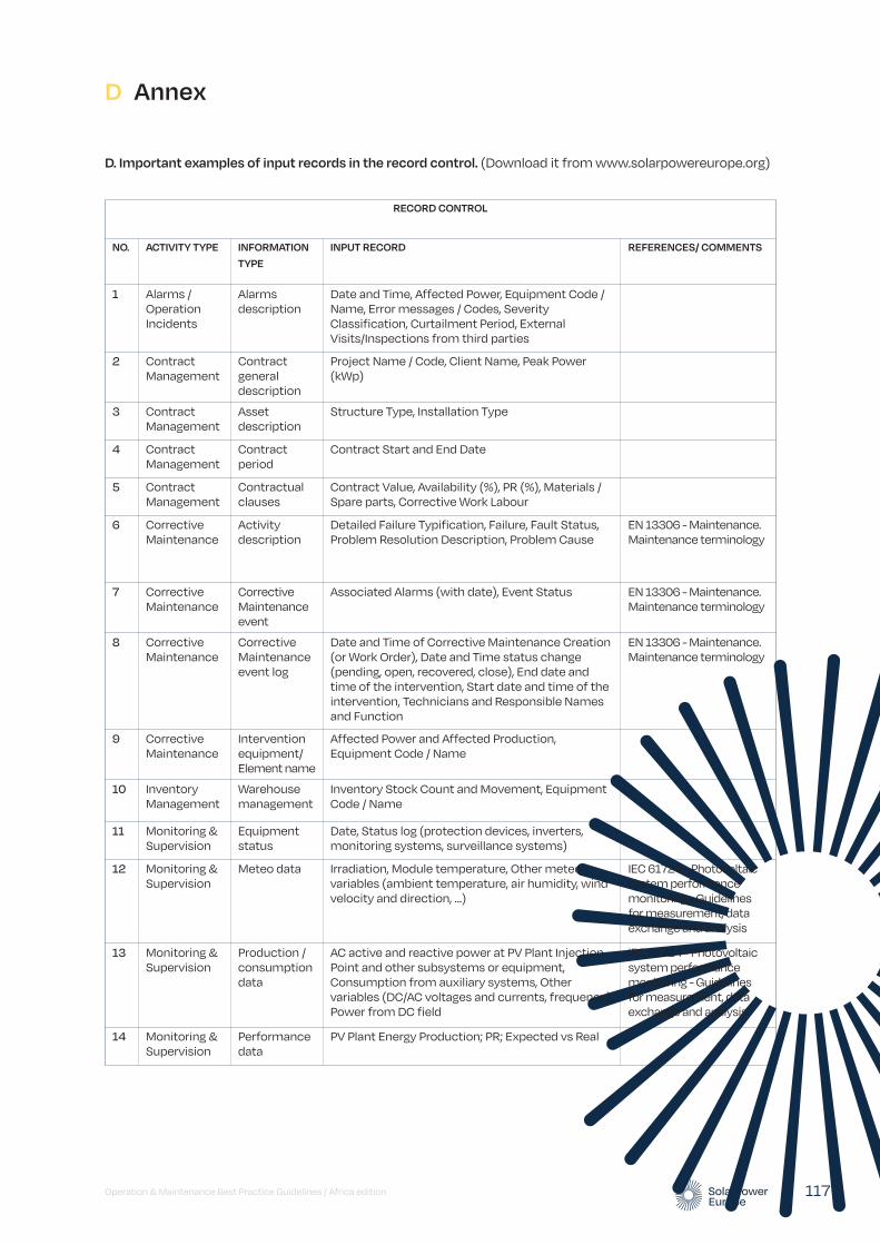
Operation & Maintenance Best Practice Guidelines / Africa edition 117
D Annex
D. Important examples of input records in the record control. (Download it from www.solarpowereurope.org)
RECORD CONTROL
NO. ACTIVITY TYPE INFORMATION TYPE
INPUT RECORD REFERENCES/ COMMENTS
1 Alarms / Operation Incidents
Alarms description
Date and Time, Affected Power, Equipment Code / Name, Error messages / Codes, Severity Classification, Curtailment Period, External Visits/Inspections from third parties
2 Contract Management
Contract general description
Project Name / Code, Client Name, Peak Power (kWp)
3 Contract Management
Asset description
Structure Type, Installation Type
4 Contract Management
Contract period
Contract Start and End Date
5 Contract Management
Contractual clauses
Contract Value, Availability (%), PR (%), Materials / Spare parts, Corrective Work Labour
6 Corrective Maintenance
Activity description
Detailed Failure Typification, Failure, Fault Status, Problem Resolution Description, Problem Cause
EN 13306 - Maintenance. Maintenance terminology
7 Corrective Maintenance
Corrective Maintenance event
Associated Alarms (with date), Event Status EN 13306 - Maintenance. Maintenance terminology
8 Corrective Maintenance
Corrective Maintenance event log
Date and Time of Corrective Maintenance Creation (or Work Order), Date and Time status change (pending, open, recovered, close), End date and time of the intervention, Start date and time of the intervention, Technicians and Responsible Names and Function
EN 13306 - Maintenance. Maintenance terminology
9 Corrective Maintenance
Intervention equipment/ Element name
Affected Power and Affected Production, Equipment Code / Name
10 Inventory Management
Warehouse management
Inventory Stock Count and Movement, Equipment Code / Name
11 Monitoring & Supervision
Equipment status
Date, Status log (protection devices, inverters, monitoring systems, surveillance systems)
12 Monitoring & Supervision
Meteo data Irradiation, Module temperature, Other meteo variables (ambient temperature, air humidity, wind velocity and direction, …)
IEC 61724 - Photovoltaic system performance monitoring - Guidelines for measurement, data exchange and analysis
13 Monitoring & Supervision
Production / consumption data
AC active and reactive power at PV Plant Injection Point and other subsystems or equipment, Consumption from auxiliary systems, Other variables (DC/AC voltages and currents, frequency), Power from DC field
IEC 61724 - Photovoltaic system performance monitoring - Guidelines for measurement, data exchange and analysis
14 Monitoring & Supervision
Performance data
PV Plant Energy Production; PR; Expected vs Real
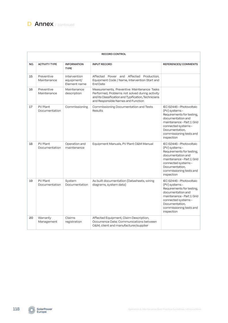
Operation & Maintenance Best Practice Guidelines / Africa edition 118
D Annex / continued
RECORD CONTROL
NO. ACTIVITY TYPE INFORMATION TYPE
INPUT RECORD REFERENCES/ COMMENTS
15 Preventive Maintenance
Intervention equipment/ Element name
Affected Power and Affected Production, Equipment Code / Name, Intervention Start and End Date
16 Preventive Maintenance
Maintenance description
Measurements, Preventive Maintenance Tasks Performed, Problems not solved during activity and its Classification and Typification, Technicians and Responsible Names and Function
17 PV Plant Documentation
Commissioning Commissioning Documentation and Tests Results
IEC 62446 - Photovoltaic (PV) systems - Requirements for testing, documentation and maintenance - Part 1: Grid connected systems - Documentation, commissioning tests and inspection
18 PV Plant Documentation
Operation and maintenance
Equipment Manuals, PV Plant O&M Manual IEC 62446 - Photovoltaic (PV) systems - Requirements for testing, documentation and maintenance - Part 1: Grid connected systems - Documentation, commissioning tests and inspection
19 PV Plant Documentation
System Documentation
As built documentation (Datasheets, wiring diagrams, system data)
IEC 62446 - Photovoltaic (PV) systems - Requirements for testing, documentation and maintenance - Part 1: Grid connected systems - Documentation, commissioning tests and inspection
20 Warranty Management
Claims registration
Affected Equipment, Claim Description, Occurrence Date; Communications between O&M, client and manufacturer/supplier
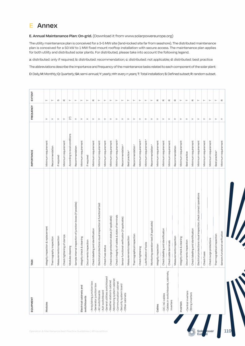
Operation & Maintenance Best Practice Guidelines / Africa edition 119
E AnnexE. Annual Maintenance Plan: On-grid. (Download it from www.solarpowereurope.org)
The utility maintenance plan is conceived for a 3-5 MW site (land-locked site far from seashore). The distributed maintenance plan is conceived for a 50 kW to 1 MW fixed mount rooftop installation with secure access. The maintenance plan applies for both utility and distributed solar plants. For distributed, please take into account the following legend.
a: distributed: only if required; b: distributed: recommendation; c: distributed: not applicable; d: distributed: best practice
The abbreviations describe the importance and frequency of the maintenance tasks related to each component of the solar plant:
D: Daily, M: Monthly; Q: Quarterly; SA: semi-annual; Y: yearly; nYr: every n years; T: Total installation; S: Defined subset; R: random subset.
EQU
IPM
ENT
TAS
KIM
POR
TAN
CE
FREQ
UEN
CYEX
TEN
T
Mod
ules
Inte
grity
insp
ectio
n &
repl
acem
ent
Min
imum
requ
irem
ent
Y T
Ther
mog
raph
y in
spec
tion
Reco
mm
enda
tion
Y T
Mea
sure
men
ts in
spec
tion
if re
quire
d Y
S
Che
ck ti
ghte
ning
of c
lam
ps
Min
imum
requ
irem
ent
Y R
Mod
ules
cle
anin
g Ac
cord
ing
to lo
cal c
ondi
tions
(Y
) T
Sam
ple
inte
rnal
insp
ectio
n of
junc
tion
boxe
s (if
pos
sibl
e)
Reco
mm
enda
tion
Y T
Elec
tric
al c
abin
ets
and
swit
chbo
ards
- Arr
ay/s
trin
g ju
ncti
on b
ox
- Gen
erat
or ju
ncti
on b
ox
- AC
sw
itch
boar
ds
- AU
X sw
itch
boar
d - G
ener
al u
tilit
ies
swit
chbo
ard
- Wea
ther
sta
tion
’s c
abin
et
- Mon
itor
ing
syst
em c
abin
et
- Com
mun
icat
ion
cabi
net
- Sec
urit
y sy
stem
boa
rd
- Oth
er c
abin
ets
Inte
grity
che
ck &
cle
anin
g M
inim
um re
quire
men
t Y
T
Doc
umen
ts in
spec
tion
if re
quire
d Y
T
Che
ck la
belli
ng a
nd id
entif
icat
ion
Min
imum
requ
irem
ent
Y R
Elec
tric
al p
rote
ctio
ns v
isua
l insp
ectio
n &
func
tiona
l tes
t M
inim
um re
quire
men
t Y
T
Che
ck fu
se s
tatu
s M
inim
um re
quire
men
t Y
T
Che
ck s
urge
pro
tect
ion
stat
us (i
f app
licab
le)
Min
imum
requ
irem
ent
Y T
Che
ck in
tegr
ity o
f cab
les
& s
tate
of t
erm
inal
s M
inim
um re
quire
men
t a
Y T
Sens
or fu
nctio
nal v
erifi
catio
n (if
app
licab
le)
Reco
mm
enda
tion
a Y
T
Mea
sure
men
ts in
spec
tion
Best
pra
ctic
e a
Y T
Ther
mog
raph
ical
insp
ectio
n Re
com
men
datio
n a
Y T
Che
ck ti
ghte
ning
M
inim
um re
quire
men
t a Y
T
Lubr
ifica
tion
of lo
cks
Min
imum
requ
irem
ent a
Y T
Mon
itorin
g op
erat
ion
test
(if a
pplic
able
) Re
com
men
datio
n a
Y T
Cab
les
- DC
/ AC
cab
les
- Cab
les
in s
wit
chbo
ards
, cab
inet
s,
in
vert
ers
Inte
grity
insp
ectio
n M
inim
um re
quire
men
t Y
R
Che
ck la
belli
ng a
nd id
entif
icat
ion
Min
imum
requ
irem
ent
Y R
Che
ck c
able
term
inal
s M
inim
um re
quire
men
t Y
R
Mea
sure
men
ts in
spec
tion
Reco
mm
enda
tion
Y R
Inve
rter
s
- Cen
tral
inve
rter
s - S
trin
g in
vert
ers
Inte
grity
che
ck &
cle
anin
g M
inim
um re
quire
men
t Y
T
Doc
umen
ts in
spec
tion
Best
pra
ctic
e Y
T
Che
ck la
belli
ng a
nd id
entif
icat
ion
Min
imum
requ
irem
ent
Y R
Elec
tric
al p
rote
ctio
ns v
isua
l insp
ectio
n, c
heck
cor
rect
ope
ratio
ns
Min
imum
requ
irem
ent
Y T
Che
ck fu
ses
Min
imum
requ
irem
ent
Y T
Che
ck s
urge
pro
tect
ions
M
inim
um re
quire
men
t Y
T
Ther
mog
raph
ical
insp
ectio
n Be
st p
ract
ice b
Y
T
Sens
ors
func
tiona
l ver
ifica
tion
Min
imum
requ
irem
ent
Y R
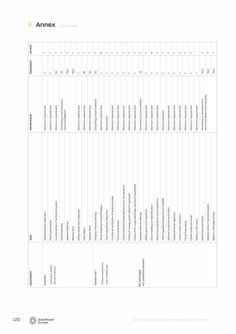
Operation & Maintenance Best Practice Guidelines / Africa edition 120
EQU
IPM
ENT
TAS
KIM
POR
TAN
CE
FREQ
UEN
CYEX
TEN
T
Inve
rter
s
- Cen
tral
inve
rter
s - S
trin
g in
vert
ers
Mea
sure
men
ts in
spec
tion
Min
imum
requ
irem
ent
Y T
Che
ck p
aram
eter
s M
inim
um re
quire
men
t Y
T
Func
tiona
l tes
t of v
entil
atio
n sy
stem
M
inim
um re
quire
men
t SA
T
Che
ck b
atte
ries
Acco
rdin
g to
man
ufac
ture
r’s
reco
mm
enda
tions
(Y
) T
Repl
ace
batt
erie
s (3
yr)
T
Repl
ace
fans
(5
yr)
T
Safe
ty e
quip
men
t ins
pect
ion
Min
imum
requ
irem
ent
Y T
Cle
an fi
lters
M
inim
um re
quire
men
t SA
T
Repl
ace
filte
rs
Min
imum
requ
irem
ent
2yr
T
Tran
sfor
mer
c
- Pow
er tr
ansf
orm
er
- AU
X tr
ansf
orm
er
Inte
grity
che
ck &
cle
anin
g Ac
cord
ing
to lo
cal c
ondi
tions
(Y
) T
Che
ck la
belli
ng a
nd id
entif
icat
ion
Min
imum
requ
irem
ent
Y R
Ther
mog
raph
ical
insp
ectio
n Be
st p
ract
ice
Y T
Func
tiona
l ver
ifica
tion
of s
enso
rs &
rela
is
Min
imum
requ
irem
ent
Y T
Che
ck p
aram
eter
s M
inim
um re
quire
men
t Y
T
Che
ck o
il lev
el (i
f app
licab
le) a
nd m
ax. t
empe
ratu
re
Min
imum
requ
irem
ent
Y T
Che
ck o
f coo
ling
syst
em (f
ans)
if a
pplic
able
M
inim
um re
quire
men
t Y
T
Che
ck o
f MV
surg
e di
scha
rger
dev
ices
(if a
pplic
able
) M
inim
um re
quire
men
t Y
T
MV
sw
itch
gear
in
cl. p
rote
ctio
n de
vice
s c
Inte
grity
che
ck &
cle
anin
g Ac
cord
ing
to lo
cal c
ondi
tions
(Y
) T
Safe
ty e
quip
men
t ins
pect
ion
Min
imum
requ
irem
ent
Y T
Che
ck la
belli
ng a
nd id
entif
icat
ion
Min
imum
requ
irem
ent
Y R
Elec
tric
al p
rote
ctio
ns v
isua
l insp
ectio
n M
inim
um re
quire
men
t Y
T
Ther
mog
raph
ical
insp
ectio
n, if
pos
sibl
e Re
com
men
datio
n Y
T
Sens
ors
func
tiona
l ver
ifica
tion
Min
imum
requ
irem
ent
Y T
Mea
sure
men
ts in
spec
tion
Min
imum
requ
irem
ent
Y T
Che
ck c
orre
ct o
pera
tion
Min
imum
requ
irem
ent
Y T
Che
ck fu
se s
tatu
s M
inim
um re
quire
men
t Y
T
Che
ck c
able
s te
rmin
als
Min
imum
requ
irem
ent
Y T
Batt
ery
/ UPS
che
ck
Min
imum
requ
irem
ent
Y
Mec
hani
cal lu
bric
atio
n Ac
cord
ing
to m
anuf
actu
rer’s
re
com
men
datio
ns a
nd n
eces
sity
(5yr
) T
Repl
ace
cert
ain
mec
hani
cal p
arts
(5
yr)
T
Batt
ery
/ UPS
repl
acem
ent
(3yr
) T
E Annex / continued
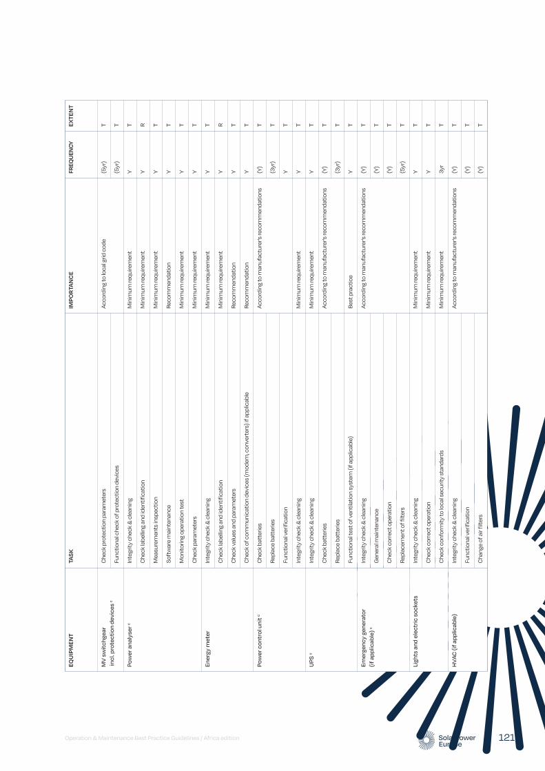
Operation & Maintenance Best Practice Guidelines / Africa edition 121
EQU
IPM
ENT
TAS
KIM
POR
TAN
CE
FREQ
UEN
CYEX
TEN
T
MV
sw
itch
gear
in
cl. p
rote
ctio
n de
vice
s c
Che
ck p
rote
ctio
n pa
ram
eter
s Ac
cord
ing
to lo
cal g
rid c
ode
(5yr
) T
Func
tiona
l che
ck o
f pro
tect
ion
devi
ces
(5yr
) T
Pow
er a
naly
ser c
Inte
grity
che
ck &
cle
anin
g M
inim
um re
quire
men
t Y
T
Che
ck la
belli
ng a
nd id
entif
icat
ion
Min
imum
requ
irem
ent
Y R
Mea
sure
men
ts in
spec
tion
Min
imum
requ
irem
ent
Y T
Soft
war
e m
aint
enan
ce
Reco
mm
enda
tion
Y T
Mon
itorin
g op
erat
ion
test
M
inim
um re
quire
men
t Y
T
Che
ck p
aram
eter
s M
inim
um re
quire
men
t Y
T
Ener
gy m
eter
Inte
grity
che
ck &
cle
anin
g M
inim
um re
quire
men
t Y
T
Che
ck la
belli
ng a
nd id
entif
icat
ion
Min
imum
requ
irem
ent
Y R
Che
ck v
alue
s an
d pa
ram
eter
s Re
com
men
datio
n Y
T
Che
ck o
f com
mun
icat
ion
devi
ces
(mod
em, c
onve
rter
s) if
app
licab
le
Reco
mm
enda
tion
Y T
Pow
er c
ontr
ol u
nit c
Che
ck b
atte
ries
Acco
rdin
g to
man
ufac
ture
r’s re
com
men
datio
ns(Y
) T
Repl
ace
batt
erie
s (3
yr)
T
Func
tiona
l ver
ifica
tion
Y T
Inte
grity
che
ck &
cle
anin
g M
inim
um re
quire
men
tY
T
UPS
cIn
tegr
ity c
heck
& c
lean
ing
Min
imum
requ
irem
ent
Y T
Che
ck b
atte
ries
Acco
rdin
g to
man
ufac
ture
r’s re
com
men
datio
ns(Y
) T
Repl
ace
batt
erie
s (3
yr)
T
Func
tiona
l tes
t of v
entil
atio
n sy
stem
(if a
pplic
able
) Be
st p
ract
ice
Y T
Emer
genc
y ge
nera
tor
(if a
pplic
able
) c
Inte
grity
che
ck &
cle
anin
g Ac
cord
ing
to m
anuf
actu
rer’s
reco
mm
enda
tions
(Y)
T
Gen
eral
mai
nten
ance
(Y
) T
Che
ck c
orre
ct o
pera
tion
(Y)
T
Repl
acem
ent o
f filt
ers
(5yr
) T
Ligh
ts a
nd e
lect
ric s
ocke
tsIn
tegr
ity c
heck
& c
lean
ing
Min
imum
requ
irem
ent
Y T
Che
ck c
orre
ct o
pera
tion
Min
imum
requ
irem
ent
Y T
Che
ck c
onfo
rmity
to lo
cal s
ecur
ity s
tand
ards
M
inim
um re
quire
men
t 3y
r T
HV
AC (i
f app
licab
le)
Inte
grity
che
ck &
cle
anin
g Ac
cord
ing
to m
anuf
actu
rer’s
reco
mm
enda
tions
(Y)
T
Func
tiona
l ver
ifica
tion
(Y)
T
Cha
nge
of a
ir fil
ters
(Y
) T
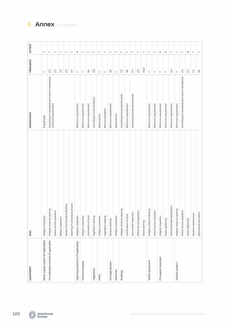
Operation & Maintenance Best Practice Guidelines / Africa edition 122
EQU
IPM
ENT
TAS
KIM
POR
TAN
CE
FREQ
UEN
CYEX
TEN
T
Wat
er s
uppl
y sy
stem
(if a
pplic
able
)In
tegr
ity in
spec
tion
If ap
plic
able
Y
T
Fire
det
ecti
on c
entr
al (i
f app
licab
leIn
tegr
ity c
heck
& c
lean
ing
Acco
rdin
g to
man
ufac
ture
r’s re
com
men
datio
ns
and
loca
l req
uire
men
ts
(Y)
T
Che
ck c
orre
ct o
pera
tion
(Y)
T
Batt
ery
insp
ectio
n (Y
) T
Sens
ors
func
tiona
l ver
ifica
tion
(Y)
T
Cle
anin
g of
cam
eras
& s
enso
rs
(Y)
T
Ligh
tnin
g pr
otec
tion
(if a
pplic
able
)In
tegr
ity in
spec
tion
Min
imum
requ
irem
ent
Y R
Fenc
es a
nd g
ates
Inte
grity
insp
ectio
n M
inim
um re
quire
men
t Y
T
Lubr
icat
ion
of lo
cks
Min
imum
requ
irem
ent
SA
T
Veg
etat
ion
Vege
tatio
n cl
earin
g Ac
cord
ing
to lo
cal c
ondi
tions
(Q
) T
Path
sIn
tegr
ity in
spec
tion
Best
pra
ctic
e Y
T
Vege
tatio
n cl
earin
g Re
com
men
datio
n Y
T
Dra
inag
e Sy
stem
Gen
eral
cle
anin
g M
inim
um re
quire
men
t SA
T
Man
hole
sIn
tegr
ity in
spec
tion
Best
pra
ctic
e Y
T
Bui
ldin
gsIn
tegr
ity c
heck
& c
lean
ing
Acco
rdin
g to
loca
l req
uire
men
ts
(Y)
T
Lubr
ifica
tion
of lo
cks
Min
imum
requ
irem
ent
SA
T
Doc
umen
ts in
spec
tion
Acco
rdin
g to
loca
l req
uire
men
ts
(Y)
T
Che
ck fi
re e
xtin
guis
hers
(Y
) T
Che
ck e
arth
ing
(3yr
) T
Safe
ty e
quip
men
tIn
tegr
ity c
heck
& c
lean
ing
Min
imum
requ
irem
ent
Y T
Che
ck c
orre
ct o
pera
tion
Min
imum
requ
irem
ent
Y T
PV s
uppo
rt s
truc
ture
Inte
grity
insp
ectio
n M
inim
um re
quire
men
t Y
R
Che
ck ti
ghte
ning
M
inim
um re
quire
men
t Y
R
Che
ck p
oten
tial e
qual
izat
ion
Min
imum
requ
irem
ent
2yr
T
Trac
ker s
yste
m c
Inte
grity
che
ck &
cle
anin
g M
inim
um re
quire
men
t Y
T
Che
ck c
orre
ct o
pera
tion
Acco
rdin
g to
man
ufac
ture
r’s re
com
men
datio
ns
(Y)
T
Che
ck ti
ghte
ning
(Y
) R
Gen
eral
mai
nten
ance
(Y
) T
Mec
hani
cal lu
bric
atio
n SA
T
E Annex / continued

Operation & Maintenance Best Practice Guidelines / Africa edition 123
EQU
IPM
ENT
TAS
KIM
POR
TAN
CE
FREQ
UEN
CYEX
TEN
T
Wea
ther
sta
tion
dIn
tegr
ity c
heck
& c
lean
ing
Acco
rdin
g to
man
ufac
ture
r’s re
com
men
datio
ns
(Y)
T
Func
tiona
l tes
t of s
enso
rs
(Y)
T
Che
ck c
orre
ct o
pera
tion
(Y)
T
Che
ck b
atte
ries
(if a
pplic
able
) (Y
) T
Mon
itorin
g op
erat
ion
test
(Y
) T
Irrad
iati
on s
enso
rsIn
tegr
ity c
heck
& c
lean
ing
Acco
rdin
g to
man
ufac
ture
r’s re
com
men
datio
ns
and
loca
l req
uire
men
ts
Q
T
Cal
ibra
tion
2yr
T
Mon
itorin
g op
erat
iona
l tes
t Y
T
Com
mun
icat
ion
Boa
rdFu
nctio
nal c
omm
unic
atio
ns c
heck
M
inim
um re
quire
men
t D
T
Intr
usio
n de
tect
ion
and
ve
rific
atio
n sy
stem
c
Inte
grity
che
ck &
cle
anin
g M
inim
um re
quire
men
t Y
T
Func
tiona
l ver
ifica
tion
of in
trus
ion
dete
ctio
n Ac
cord
ing
to m
anuf
actu
rer’s
reco
mm
enda
tions
(Y)
T
Func
tiona
l ver
ifica
tion
of a
larm
ing
Y T
Func
tiona
l ver
ifica
tion
of c
amer
as
M
T
Spec
ific
mai
nten
ance
Y
T
Stoc
k of
spa
re p
arts
dIn
vent
ory
of s
tock
M
inim
um re
quire
men
t Y
T
Visu
al in
spec
tion
of s
tock
con
ditio
ns
Min
imum
requ
irem
ent
Y T
Stoc
k re
plen
ishm
ent
Min
imum
requ
irem
ent
M
T
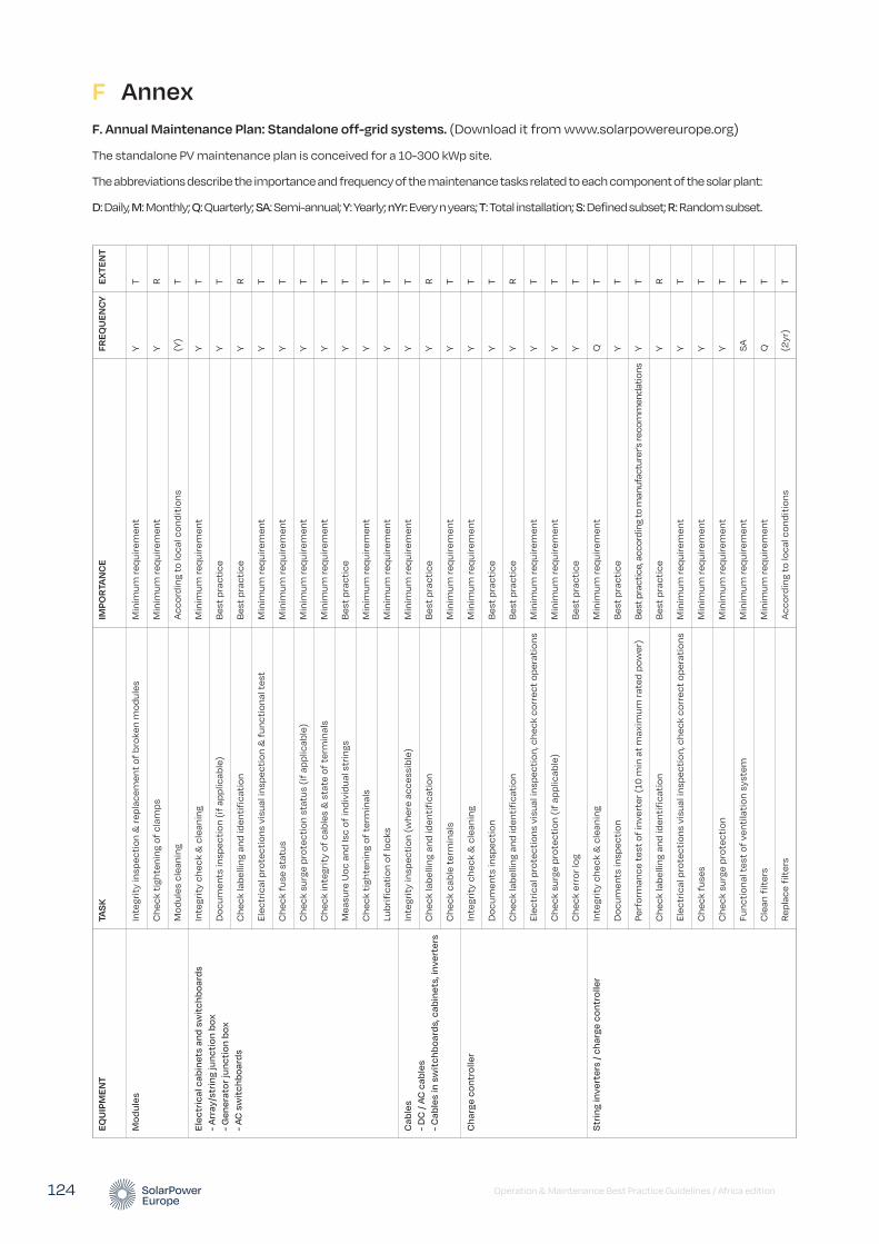
Operation & Maintenance Best Practice Guidelines / Africa edition 124
F AnnexF. Annual Maintenance Plan: Standalone off-grid systems. (Download it from www.solarpowereurope.org)
The standalone PV maintenance plan is conceived for a 10-300 kWp site.
The abbreviations describe the importance and frequency of the maintenance tasks related to each component of the solar plant:
D: Daily, M: Monthly; Q: Quarterly; SA: Semi-annual; Y: Yearly; nYr: Every n years; T: Total installation; S: Defined subset; R: Random subset.
EQU
IPM
ENT
TAS
KIM
POR
TAN
CE
FREQ
UEN
CY
EXTE
NT
Mod
ules
Inte
grit
y in
spec
tion
& re
plac
emen
t of
bro
ken
mod
ules
Min
imum
requ
irem
ent
YT
Che
ck t
ight
enin
g of
cla
mps
Min
imum
requ
irem
ent
YR
Mod
ules
cle
anin
gA
ccor
ding
to
loca
l con
diti
ons
(Y)
T
Elec
tric
al c
abin
ets
and
swit
chbo
ards
-
Arr
ay/s
trin
g ju
ncti
on b
ox
- G
ener
ator
junc
tion
box
-
AC s
wit
chbo
ards
Inte
grit
y ch
eck
& c
lean
ing
Min
imum
requ
irem
ent
YT
Doc
umen
ts in
spec
tion
(if
appl
icab
le)
Bes
t pr
acti
ceY
T
Che
ck la
belli
ng a
nd id
enti
fica
tion
Bes
t pr
acti
ceY
R
Elec
tric
al p
rote
ctio
ns v
isua
l ins
pect
ion
& f
unct
iona
l tes
tM
inim
um re
quir
emen
tY
T
Che
ck f
use
stat
usM
inim
um re
quir
emen
tY
T
Che
ck s
urge
pro
tect
ion
stat
us (i
f ap
plic
able
)M
inim
um re
quir
emen
tY
T
Che
ck in
tegr
ity
of c
able
s &
sta
te o
f te
rmin
als
Min
imum
requ
irem
ent
YT
Mea
sure
Uoc
and
Isc
of in
divi
dual
str
ings
Bes
t pr
acti
ceY
T
Che
ck t
ight
enin
g of
ter
min
als
Min
imum
requ
irem
ent
YT
Lubr
ific
atio
n of
lock
sM
inim
um re
quir
emen
tY
T
Cab
les
- D
C /
AC c
able
s -
Cab
les
in s
wit
chbo
ards
, cab
inet
s, in
vert
ers
Inte
grit
y in
spec
tion
(whe
re a
cces
sibl
e)M
inim
um re
quir
emen
tY
T
Che
ck la
belli
ng a
nd id
enti
fica
tion
Bes
t pr
acti
ceY
R
Che
ck c
able
ter
min
als
Min
imum
requ
irem
ent
YT
Cha
rge
cont
rolle
rIn
tegr
ity
chec
k &
cle
anin
gM
inim
um re
quir
emen
tY
T
Doc
umen
ts in
spec
tion
Bes
t pr
acti
ceY
T
Che
ck la
belli
ng a
nd id
enti
fica
tion
Bes
t pr
acti
ceY
R
Elec
tric
al p
rote
ctio
ns v
isua
l ins
pect
ion,
che
ck c
orre
ct o
pera
tion
sM
inim
um re
quir
emen
tY
T
Che
ck s
urge
pro
tect
ion
(if
appl
icab
le)
Min
imum
requ
irem
ent
YT
Che
ck e
rror
log
Bes
t pr
acti
ceY
T
Str
ing
inve
rter
s / c
harg
e co
ntro
ller
Inte
grit
y ch
eck
& c
lean
ing
Min
imum
requ
irem
ent
QT
Doc
umen
ts in
spec
tion
Bes
t pr
acti
ceY
T
Perf
orm
ance
tes
t of
inve
rter
(10
min
at
max
imum
rate
d po
wer
)Be
st p
ract
ice,
acc
ordi
ng to
man
ufac
ture
r's re
com
men
datio
nsY
T
Che
ck la
belli
ng a
nd id
enti
fica
tion
Bes
t pr
acti
ceY
R
Elec
tric
al p
rote
ctio
ns v
isua
l ins
pect
ion,
che
ck c
orre
ct o
pera
tion
sM
inim
um re
quir
emen
tY
T
Che
ck f
uses
Min
imum
requ
irem
ent
YT
Che
ck s
urge
pro
tect
ion
Min
imum
requ
irem
ent
YT
Func
tion
al t
est
of v
enti
lati
on s
yste
mM
inim
um re
quir
emen
tSA
T
Cle
an f
ilter
sM
inim
um re
quir
emen
tQ
T
Rep
lace
filt
ers
Acc
ordi
ng t
o lo
cal c
ondi
tion
s(2
yr)
T
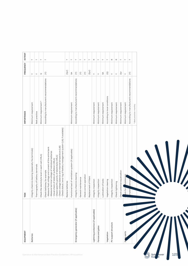
Operation & Maintenance Best Practice Guidelines / Africa edition 125
EQU
IPM
ENT
TAS
KIM
POR
TAN
CE
FREQ
UEN
CY
EXTE
NT
Bat
teri
esIn
tegr
ity
chec
k &
cle
anin
g (e
spec
ially
the
ter
min
als)
Min
imum
requ
irem
ent
YT
Ther
mog
raph
y of
bat
tery
ter
min
als
Bes
t pr
acti
ceY
T
Che
ck t
he e
lect
roly
te le
vel i
n ea
ch c
ell (
VR
LA)
Min
imum
requ
irem
ent
*Q
T
Che
ck b
atte
ries
, for
exa
mpl
e -
Mea
sure
flo
at v
olta
ge a
nd c
urre
nt o
f th
e en
tire
ban
k -
Mea
sure
ter
min
al v
olta
ge o
f in
divi
dual
bat
teri
es
- V
isua
l che
ck o
f st
ate
of s
ulfa
tion
(VR
LA)
- C
heck
spe
cifi
c gr
avit
y of
ele
ctro
lyte
(VR
LA)
- C
heck
vol
tage
bal
ance
and
inte
rnal
tem
pera
ture
(LIB
) -
Che
ck s
tatu
s / e
rror
log
of b
atte
ry m
anag
emen
t sy
stem
(LIB
, if
avai
labl
e)
Acc
ordi
ng t
o m
anuf
actu
rer's
reco
mm
enda
tion
s(Y
)T
Rep
lace
bat
teri
es(3
yr)
T
Func
tion
al t
est
of v
enti
lati
on s
yste
m (i
f ap
plic
able
)M
inim
um re
quir
emen
tSA
T
Emer
genc
y ge
nera
tor (
if a
pplic
able
)In
tegr
ity
chec
k &
cle
anin
gA
ccor
ding
to
man
ufac
ture
r's re
com
men
dati
ons
(Y)
T
Gen
eral
mai
nten
ance
(Y)
T
Che
ck c
orre
ct o
pera
tion
(Y)
T
Rep
lace
men
t of
filt
ers
(5yr
)T
Ligh
tnin
g pr
otec
tion
(if
appl
icab
le)
Inte
grit
y in
spec
tion
Min
imum
requ
irem
ent
YR
Fenc
es a
nd g
ates
Inte
grit
y in
spec
tion
Min
imum
requ
irem
ent
YT
Lubr
icat
ion
of lo
cks
Min
imum
requ
irem
ent
SAT
Veg
etat
ion
Veg
etat
ion
clea
ring
Acc
ordi
ng t
o lo
cal c
ondi
tion
s(Q
)T
PV s
uppo
rt s
truc
ture
Inte
grit
y in
spec
tion
Min
imum
requ
irem
ent
YR
Che
ck t
ight
enin
gM
inim
um re
quir
emen
tY
R
Che
ck p
oten
tial
equ
aliz
atio
nM
inim
um re
quir
emen
t2
yrT
Spa
re p
arts
Che
ck f
or c
ompl
eten
ess
Min
imum
requ
irem
ent
YT
Com
plet
e sp
are
part
sA
ccor
ding
to
man
ufac
ture
r's re
com
men
dati
ons
(Y)
T
* B
est
prac
tice
: mon
thly

SolarPower Europe - Leading the Energy Transition Rond-point Robert Schuman 2-4, 1040 Brussels, Belgium T +32 2 709 55 20 / F +32 2 725 32 50 [email protected] / www.solarpowereurope.org
ISBN NUMBER 9789464073461