operating systems dca 2302 - bangladesh open … · operating systems dca 2302 ... book is offered...
TRANSCRIPT
OPERATING SYSTEMS DCA 2302
SCHOOL OF SCIENCE AND TECHNOLOGY
BANGLADESH OPEN UNIVERSITY

SCHOOL OF SCIENCE AND TECHNOLOGY
DCA 2302
OPERATING SYSTEMS
BANGLADESH OPEN UNIVERSITY
Course Development Team
Writer
Mohammod Shamim Hossain
School of Science and Technology Bangladesh Open University
Co-ordinator Mohammod Shamim Hossain
School of Science and Technology Bangladesh Open University
Editor
Mofiz Uddin Ahmed School of Science and Technology
Bangladesh Open University
OPERATING SYSTEMS
Editorial Board
Professor M. Lutfar Rahman Director, Computer Centre
University of Dhaka
Professor M. Kaykobad Head, Department of Computer Science & Engineering Bangladesh University of Engineering and Technology
Professor Mofiz Uddin Ahmed
Dean, School of Science and Technology Bangladesh Open University
Dr. K. M. Rezanur Rahman
Assistant Professor School of Science and Technology
Bangladesh Open University
Anwar Sadat Lecturer
School of Science and Technology Bangladesh Open University
Published by : Publishing, Printing & Distribution Division Bangladesh Open University, Gazipur-1704 September 1998 School of Science and Technology Bangladesh Open University, Gazipur-1704 ISBN 984-34-4001-3
Computer Composed by : Md. Jakir Hossain & Md. Sharif Uddin, Desktop Processing by : Md. Jakir Hossain, Cover Design : Monirul Islam.
Printed by : Ganim Printing & Packages, 44/A/1/2 Azimpur Road, Dhaka- 1205.


Operating Systems Contents Unit 1 : Introduction to Operating System Lesson 1 : Introduction to OS and System Software ........................…………………… 1 Lesson 2 : Serial Batch Processing and Multiprogramming .....……………………… 10 Lesson 3 : Time Sharing and Multiprocessing Operating Systems ……………………. 15 Lesson 4 : Real-Time and Virtual Storage Operating System ........……………………. 20 Lesson 5 : Functions and Evaluation of Operating System …......……………………. 25 Unit 2 : Computer and Operating System Structure Lesson 1 : Interrupts and I/O Structure ………………....................…………………… 35 Lesson 2 : System Calls and System Program .................................…………………… 40 Lesson 3 : Operating System Structure .............................................…………………… 45 Unit 3 : Process Management Lesson 1 : Process Concept..............................................................……………………. 51 Lesson 2 : Scheduling Concept .......................................................……………………. 57 Lesson 3 : Scheduling Criteria and Algorithms ..............................……………………. 62 Lesson 4 : Priority, Preemptive and Round Robin Scheduling Algorithms …………. 70 Unit 4 : Deadlock Lesson 1 : Introduction of Deadlock .................................................…………………… 79 Lesson 2 : Deadlock Modeling........................................................……………………. 85 Lesson 3 : Deadlockoidance.....................................……………………………………. 91 Lesson 4 : Deadlock Recovery …………………………………………………………. 97 Unit 5 : Primary Memory Management Lesson 1 : Relocation, Protection and Sharing ................................……………………. 101 Lesson 2 : Swapping ………………………......................................…………………… 106 Lesson 3 : Paging …………………………………………………….…………………… 113 Lesson 4 : Segmentation ………………………………………………………………… 117 Lesson 5 : Virtual Memory Concept ..................................................…………………… 123 Unit 6 : Secondary Storage Management Lesson 1 : Introduction to Disk .........................................................…………………… 131 Lesson 2 : Disk Scheduling Algorithm ...........................................……………………. 135 Lesson 3 : Free Space Management …………………………………………………… 142 Lesson 4 : Allocation Methods........................................................……………………. 146 Unit 7 : File Management Lesson 1 : File Organization and File Systems................................……………………. 153 Lesson 2 : File Access Methods .......................................................……………………. 161 Lesson 3 : Security ………………..................................................……………………. 166 Lesson 4 : Authentication …………………………………………………………………. 174 Lesson 5 : File Protection and Cryptography ...................................…………………… 179

Unit 8 : DOS Lesson 1 : Structure and Process in MS-DOS ..................................……………………. 185 Lesson 2 : Memory Management in DOS .......................................……………………. 191 Lesson 3 : MS-DOS File System ........................................................……………………. 196 Lesson 4 : User Interface in Windows …………………………………………………… 201 Unit 9 : UNIX Lesson 1 : Features of UNIX ……………………………………………………………… 215 Lesson 2 : User and Programmer Interface ……………………………………………… 222 Lesson 3 : Memory Management in UNIX ……………………………………………… 229 Lesson 4 : Process Control ………………………………………………………………… 232 Lesson 5 : File System, Disk and Directory Structure …..……………………………… 236 Lesson 6 : UNIX Commands ……………………………………………………………… 245 Answer to the MCQs .................................................................…………………. 255

PREFACE An operating system is an integrated set of programs that directs and manages the components and resources of a computer system. The basic resources of a computer system are provided by its hardware, software and data. In order to achieve that best possible performance operating system controls and coordinators resources such as the CPU, other processing units, both primary and secondary storage and all input/output devices. Operating system theory have reached a considerable level of maturity and stability. Operating systems designers have the foundation, the tools and the opportunity innovative system to meet the challenges of these exciting times. This book is offered as a guide to the principles and practice of operating system design. It attempts to bridge the entrenched gap between the theory and practice of operating system design by relying on a thorough theoretical foundation. It covers all the fundamental principles in detail, including processes, inter-process communication, semaphores, monitors, message passing, remote procedure call, scheduling algorithms, input/output, deadlocks, device drivers, memory management’s, paging algorithms, file system design, security and protection mechanisms. The book is organized into 9 units. The coverage is modular in the sense that certain unit or group of units are self sufficient. Each unit is divided into several lessons. Unit 1 provides an overview of the conceptual evaluation of operating systems. Different types of operating system, such as, serial batch processing, multiprogramming, time sharing and multiprocessing, real time and virtual storage operating system, read time and virtual storage operating system have been discussed. Some common classes of operating systems functions are also stated here. Unit 2 Illustrates the interrupt method of a computer system. Once of the important function of operating system i.e. handling I/O operations has been discussed. Four different OS structures were discussed i.e. monolithic system, client server approach, virtual machine etc. Unit 3 introduces the concept of process. A detailed discussion about process state and control block is provided. The unit also includes scheduling concept, different types of scheduling techniques and algorithms. Unit 4 explains the problem of deadlocks arising from concurrent execution of processes. Along with this common techniques for dealing with it are presented. A system resource allocation graph illustrates the deadlock modeling. The strategies

for deadlock avoidance and recovery from deadlock are described with several algorithm. Unit 5 explains the issues involved in the management of primary memory and presents several memory management techniques based on contiguous allocation of memory. Hardware support for static and dynamic partitioning of memory as well as segmentation is discussed. Unit 6 describes secondary storage management. Different disk scheduling algorithms are presented here. Efficient management techniques and allocation methods of free spaces of secondary storage are also stated. Unit 7 deals with file organization, operation, access method, protection and security. Unit 8 discusses the structure and process in MS-DOS. The memory management techniques, file system are also discussed. Various features of Windows are stated here. Unit 9 describes the features of UNIX. Command and system call user’s are presented before the implementation of UNIX is discussed. A listing of commands are also given at the end.

Unit 1 : Introduction to Operating System
An operating system (OS) is an important part of almost every computer system. Most computer users have had some experience with an operating system, but it is difficult to pin down precisely what an operating system. An OS is an integrated set of programs that directs and manages the components and resources of a computer system, including main memory, the CPU and the peripheral devices. The OS1 is somewhat like a house keeper in that it tidies, organizes and maintains the functioning of various devices. The task of an operating system is to manage the hardware carefully, in order to achieve the best possible performance. This is accomplished by the operating system's controlling and coordinating such resources as the CPU, other processing units, both primary memory and secondary storage, and all input/output devices. The hardware provides raw computing power and the operating system makes this power conveniently accessible to the user. This unit presses what operating system do and basics of OS. Lesson 1 : Introduction to OS and System
Software 1.1. Learning Objectives On completion of this lesson you will be able to know : the purpose of operating system. an OS and system software the control and service programs that constitute an operating
system the operation of the command processor and interrupt
handler the operation of the I/O control system system software and its classification.
1 OS - means Operating system S/W - means Software
An OS is a collection of system programs that control and co-ordinate the over all operation of a computer.

Introduction to Operating System
2
1.2. Operating System An operating system is an organized collection of software that controls the overall operations of a computer. In other words, an operating system is a program that acts as an interface between a user of a computer and computer hardware. The primary goal of an OS is to make the computer system convenient to use. A secondary goal is to use the computer hardware in an efficient manner. 1.3. Purposes of an Operating System The purposes of an operating system are as follows.
It minimizes the computer user's intervention in and concern about machine's internal workings.
It provides an environment in which a user may execute programs.
It controls and co-ordinates the use of hardware among the various application programs.
It acts as a managers of resources (hardware2 and software) and allocates them to specific programs.
It controls the various I/O devices and user programs. It maximizes the overall efficiency and effectiveness of the
system. It provides an environment within which other programs
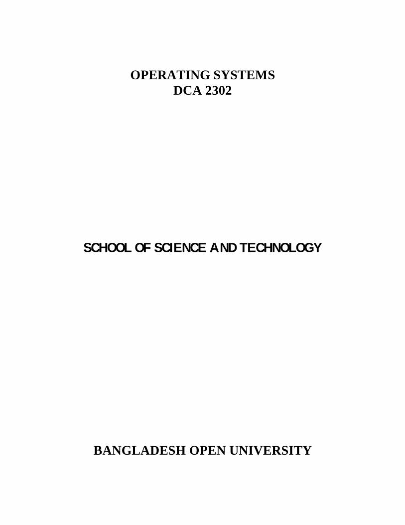
can do useful work. Computer System A computer system consist of hardware (CPU, memory, I/O devices), system software (operating system), application programs (compilers, DBMS, Editor, spreadsheets) and the users Fig. 1.1. The hardware provides the basic computing resources. The applications programs define the ways in which these resources are used to solve the computing problems of the users. The operating system controls and co-ordinates the use of the hardware among the various application programs. 2 h/w - means hardware
Purposes
Computer System
Operating System
3
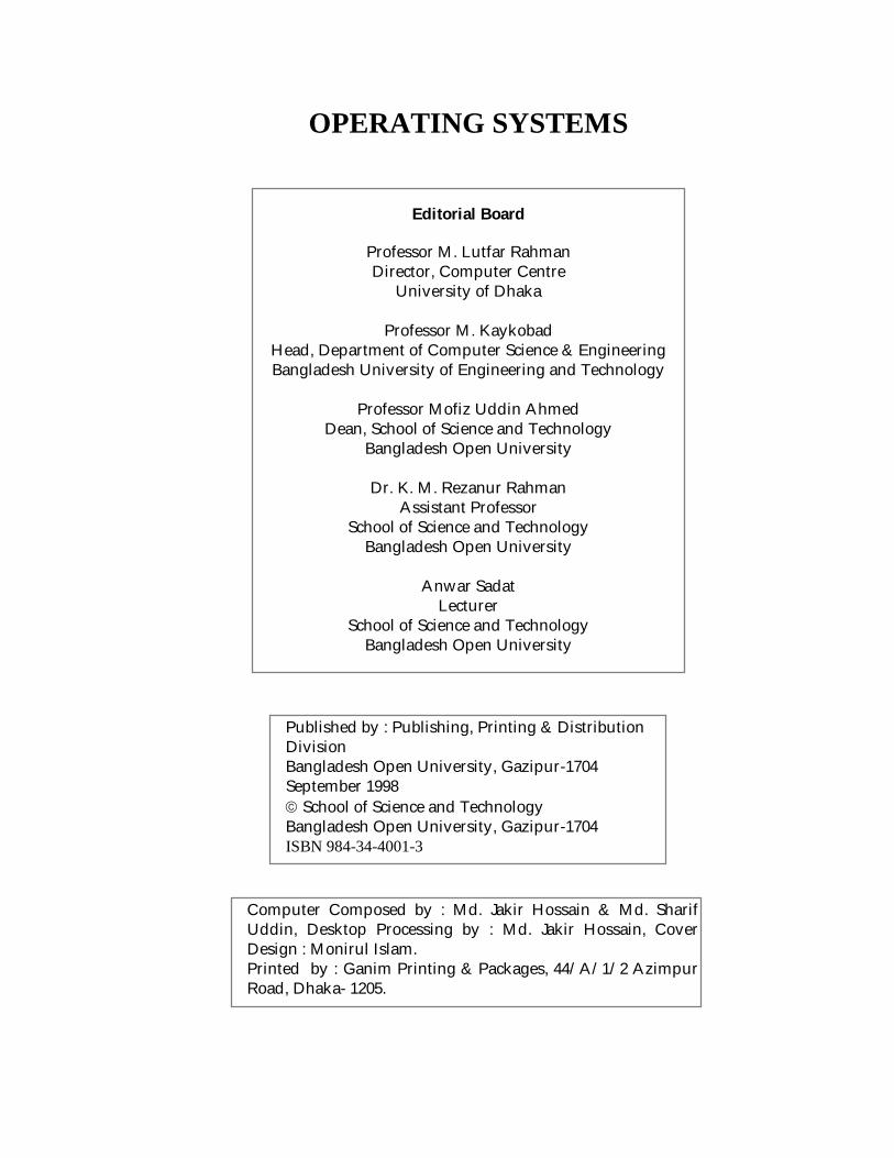
Fig. 1.1 : Elements of a computer system. 1.4. Components of an Operating System An operating system is made up of control program and service programs. These are as follows: Fig. 1.2 : Components of an operating system. 1.4.1. Control Programs Control programs permit user-computer communication, log jobs, and oversee the overall computer operation to ensure that
Hardware
Operating System
Control Programs
Service Programs
System Software
Application Software
What makes up an operating system?

Introduction to Operating System
4
the various activities run smoothly and to completion. The principal control programs are shown in Fig. 1.3. Supervisor Program The major operating system control program is commonly called the supervisor. The supervisor handles the overall management of a computer system. It is maintained in memory and it supervises the loading of other parts of the operating system from secondary storage into main memory as they are needed. It also supervises the loading of application programs for execution. The supervisor also interprets user messages and it keeps track of jobs.
Fig.1.3 : The principal control programs of an operating system. Command Interpreter The portion of the operating system that can accept, interpret and carry out user commands is referred to as the command interpreter. The command interpreter consists of a number of individual program modules, each responsible for handling a single command. Individual user commands to COPY a file, FORMAT a disk and so on, are handled by the command interpreter. Commands to the operating system of a microcomputer are actually requests to execute individual command interpreter programs. For example, the command
Input /Output Control System
Control Programs
Interrupt Handler
Command Interpreter
Supervisor
The major operating system control program is commonly called the supervisor.
The portion of the operating system that can accept, interpret and carry out user commands is referred to as the command interpreter.

Operating System
5
COPY SUM B :
directs the command processor to execute the memory-resident copy program, whereas the command
FORMAT B : requests the externally stored format program to be executed. Interrupt Handler The interrupt handler acknowledges and processes all interruptions to the system. One of the most common sources of interrupts is from I/O devices such as the keyboard, printer, and secondary storage. These devices must communicate with the CPU through the operating system. Thus the operating system is never idle, but must constantly be on the alert for an interrupt triggered by internal or external events, such as an I/O device indicating that it has completed its task or that an error condition may have occurred. The function of the interrupt handler can vary greatly from a microcomputer system to a mainframe system. Most microcomputer systems handle only one task at a time. Hence, interrupts generally come from the particular device being used at that moment, or from a user-initiated activity, such as a command issued from the keyboard to load a program, execute a program, or abort job. The handling of interrupts is more complex in a mainframe environment. Unlike microcomputer systems, mainframe systems must perform a number of tasks at the same time if the resources of the system are to be used efficiently. This generally required that the CPU jump back and forth between a number of tasks or application programs being processed in the computer at the same time. Input/ Output Control System The input/output control system (IOCS) schedules and activates the proper I/O3 device as well as the storage unit. It also monitors the operation of input/output devices. If a needed device is not
3 I/O - means input/output
The interrupt handler acknowledge and processes all interruptions to the system.
The input/output control system (IOCS) schedules and activates the proper I/O device as well as the storage unit.

Introduction to Operating System
6
available, the IOCS will substitute another device in its place. It controls and coordinates the flow of data between I/O devices, for example, from a terminal keyboard to a display screen, or to other output devices like disk drives and printers. On a microcomputer system IOCS control program is generally maintained in ROM and referred to as the BIOS (basic input/ output system). The IBM PC BIOS is stored on a set of two or four proprietary PROM chips and represents an important area of difference between an IBM PC and PC compatibles or clones. The role of the IOCS in loading a Pascal program, follows.
1. The Pascal compiler disk is inserted and a load command is entered.
2. The command processor interprets the command and executes the load program.
3. The load program assigns the job to IOCS. 4. IOCS directs the following operations :
a) Determine the location of the Pascal compiler from the disk directory.
b) Direct the read/write heads to the correct track on the disk.
c) Read the compiler from disk into memory. 5. The IOCS returns control to the load program (Step 3
reversed). 6. The operating system awaits the user's next command.
1.4.2. Service Programs In addition top control programs operating system also include service program. There are two types of service programs: utility and library programs, which perform a variety of labor-saving tasks and functions for the programmer. Whenever a specific tack is required, the appropriate service program is accessed and executed by the operating system.
Fig. 1.4 : The principal service programs.
Service Program
Utility Programs
Library Programs
Routines that aid the development and use of software.
Operating System
7
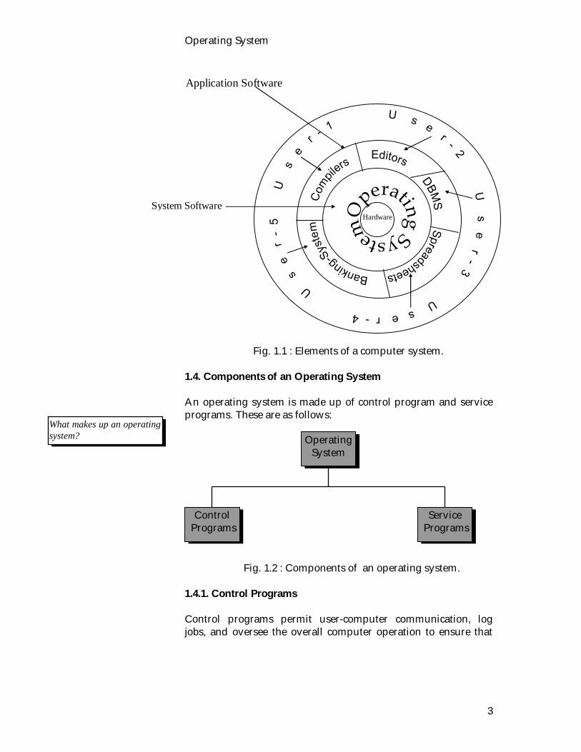
Utility Program Utility programs give the user greater control over the computer system through efficient file management. For example, file can be easily prepared, copied, deleted, merged, sorted, and updated by using the appropriate utility programs. Library Program The library program maintains a directory of frequently used software modules and their locations. These programs might consist of manufacturer-supplied or user-written routines or complete programs to compute mathematical functions, control input/output devices, maintain appointments, and so on. The library program makes these routines available when requested by the user, the operating system, or an application program. 1.5. System Software System Software consists of programs designed to facilitate the use of the computer by the user. These programs perform such standard task as organizing and maintaining data files, translating programs written in various languages to a language acceptable to the hardware, scheduling jobs through the computer as well as aiding in other areas of general computer operations. System software refers to programs that are tools to assist the computer user to generate application programs, debug and test them, modify them and, finally execute them. These programs are generally written by the computer manufacturer for one specific computer or system. The same system programs can be used by many different users and many different application programs. System Software can be classified as follows.
System Development Translator program User program
development
System Support Service program System performance System security
System Control Operating System Data Management Data Communication
System Software
System software consist of programs which manage the operation of computer itself.
The library program maintains a directory of frequently used software modules and their locations.
Introduction to Operating System
8
Fig. 1.5 : Classification of system software. The most fundamental of all the system programs is the operating system, which controls all the computer's resources and provides the base upon which application programs can be written. 1.6. Exercise 1.6.1. Multiple choice questions 1. System software consists of i) programs ii) hardware iii) monitor iv) all of the above. 2. The operating system acts as an interface between i) The user of a computer and computer hardware. ii) User and computer software. iii) Hardware and software. iv) None of the above. 3. IOCS stands for i) Input/output communication system. ii) Input/output control system. iii) Interrupt output control system. iv) None of the above. 4. How many types of service programs are there? i) 2 ii) 3 iii) 4 iv) None of the above.
1.6.2. Questions for short answers a) What do you understand by operating system? b) What are the purposes of an operating system? c) What do you understand by computer system? List the
components of a computer system. d) Define system software. Describe its classification.

Operating System
9
e) What do you understand by OS and system software? f) What are the tasks of a supervisor program? g) Explain the operation of the command interpreter. h) Describe the operations of I/O control system. i) What are the fundamental tasks of an OS? 1.6.3. Analytical questions a) What do you know about control programs? Describe
briefly. b) What are the two general categories of an OS? Describe
briefly.

Introduction to Operating System
10
Lesson 2 : Serial Batch Processing and
Multiprogramming Operating systems can be classified in a number of ways : by how they organize primary memory, by how many different programs they can execute concurrently, by what kind of secondary storage devices they use for work areas, by the setting in which they are to be used, or by the basic design of their components. So, operating system can be classified according to above outstanding characteristics, but some overlap occurs among the categories. We will divide operating system into six types :
serial batch-processing multiprogramming time sharing multiprocessing real time and virtual storage operating system.
Let us start with the simple class, the serial batch processing operating system. 2.1. Learning Objective On completion of this lesson you will be able to know : serial batch processing system advantages and disadvantages of serial batch processing
system multiprogramming system merits and demerits of multiprogramming system. 2.2. Serial Batch Processing Systems Serial batch processing operating systems can run only a single user program at a time. These are simple systems generally used on mainframes that run in batch mode and on single-user microcomputers. In another words, a system in which a number of similar items or transactions to be processed are grouped (bathed) for sequential processing during a machine run. For example, suppose the operators received one FORTRAN job, one
Running one program at a time.

Operating System
11
COBOL job and another FORTRAN job. If they ran them in that order, they would have to set up for FORTRAN (load the compiler tapes), then set up for COBOL and finally set up for FORTRAN again. If they ran the two FORTRAN programs as a batch, however, they could set up only once for FORTRAN, saving operator time. The following diagram shows how each program is run before the next begins. Fig.1.6 : Serial-batch processing operating systems. advantages
It allows a computer to be dedicated to a specific use. It is less complex. There is only one user at a time. There is no possibility that multiple programs will
deadlock. disadvantages
A long turnaround time is needed. Batch systems are slow in both processing and output. In batch system the programs must be debugged
statically. CP/M, DOS, and Macintosh operating system are the example of serial batch-processing systems.
advantages
disadvantages
Job C
Job A
Job B
Jobs executedsequentially by
the CPU.
OUTPUT LISTINGS
SYSTEM
OPERATI
NG
PROGRAM INPUTS

Introduction to Operating System
12
2.4. Multiprogramming Operating System This system involves simultaneous handling of multiple independent programs by interleaving or overlapping their execution. Multiprogramming is similar to what a chef does in the preparation of a multi-course meal. First, one dish is worked on, then it is set aside while another is attended to, and so on until the entire meal is ready at the same time. Multiprogramming is similar to the work of a lawyer. A lawyer does not have only one client at a time. Rather several clients may be in the process of being served at the same time. While one case is waiting to go to trial or for papers to be typed, the lawyer can work on another case; with enough clients, a lawyers need never be idle. Multiprogramming operating systems can execute several jobs concurrently by switching the attention of the CPU back and forth among them. This switching is usually prompted by a relatively slow input, output or storage request that can be handled by a buffer, spooler or channel, freeing the CPU to continue processing (Fig. 1.7) Fig. 1.7 : Multiprogramming operating systems.
Running several program concurrently.
Job A Job B Job C Job D
Job A Job B
Job A executingJob B executingJob C executingJob D executing
.
...
.
.
Job C Job D
OPERATING
SYSTEM
Jobs areexecutedconcurrently,utilizing CPUtime spent byothers jobsawaiting I/O orstorage.
MULTIPLEOUTPUTS
MULTIPLEINPUTS

Operating System
13
The primary reason multiprogramming operating systems were developed, and the reason they are popular, is that they enable the CPU to be utilized more efficiently. If the operating system can quickly switch the CPU to another task whenever the one being worked on requires relatively slow input, output, or storage operations, then the CPU is not allowed to stand idle. This means that more can be accomplished during a given amount of time. For example, if a particular program needs to read data from a disk drive, that task can be delegated to channel and the CPU can be put to work on another program while the data are being read in. Multiprogramming is thus an effective way to keep the fast-working CPU busy with computations while slower input, output, and storage operations are being carried out. advantages
it increases CPU utilization it decreases total real time needed to execute a job it maximizes the total job throughput of a computer.
Throughput is the amount of work accomplished in a given time interval. disadvantages
it is fairly sophisticated and more complex than serial batch processing operating system.
a multiprogramming operating systems must keep track of all the jobs it is concurrently running.
UNIX, Pick and IMB VM can be classified as multiprogramming operating system.
Advantages
disadvantages
Introduction to Operating System
14
2.5. Exercise 2.5.1. Multiple choice questions 1. Which is appropriate for serial batch processing systems? i) Running several programs at a time. ii) Running one programs at a time. iii) Handling of multiple dependent programs at a time. iv) None of the above. 2. Which is the false statement? i) A long turnaround time is needed for serial batch system. ii) Batch systems are slow in both input and output. iii) Batch systems are slow in both processing and output. iv) A batch system is less complex 3. Multiprogramming increases i) real time ii) execution time iii) CPU utilization iv) minimizes throughput. 2.5.2. Questions for short answers a) What do you understand by serial batch processing? b) List some advantages of serial batch systems. c) What are the disadvantages of serial batch processing
systems? d) List some of the disadvantages of the multiprogramming
systems. 2.5.3. Analytical questions a) What do you understand by serial batch processing
system? Illustrate with examples. b) What are the reason for developing multiprogramming
systems? c) Describe the multiprogramming operating system. d) Why do multiprogramming systems remain popular?
Operating System
15
Lesson 3 : Time Sharing and Multiprocessing
Operating Systems 3.1. Learning Objectives On completion of this lesson you will be able to : understand the time sharing systems distinguish between time sharing and multiprogramming
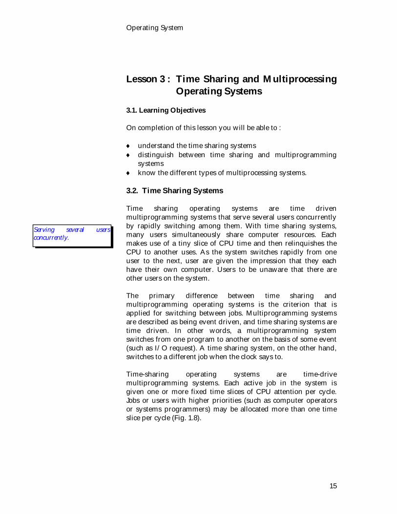
systems know the different types of multiprocessing systems. 3.2. Time Sharing Systems Time sharing operating systems are time driven multiprogramming systems that serve several users concurrently by rapidly switching among them. With time sharing systems, many users simultaneously share computer resources. Each makes use of a tiny slice of CPU time and then relinquishes the CPU to another uses. As the system switches rapidly from one user to the next, user are given the impression that they each have their own computer. Users to be unaware that there are other users on the system. The primary difference between time sharing and multiprogramming operating systems is the criterion that is applied for switching between jobs. Multiprogramming systems are described as being event driven, and time sharing systems are time driven. In other words, a multiprogramming system switches from one program to another on the basis of some event (such as I/O request). A time sharing system, on the other hand, switches to a different job when the clock says to. Time-sharing operating systems are time-drive multiprogramming systems. Each active job in the system is given one or more fixed time slices of CPU attention per cycle. Jobs or users with higher priorities (such as computer operators or systems programmers) may be allocated more than one time slice per cycle (Fig. 1.8).
Serving several users concurrently.
Introduction to Operating System
16
JOBA JOBB JOBC JOBD JOBB
JOBA JOBB JOBC JOBD JOBB
JOBA JOBB JOBC JOBD JOBB
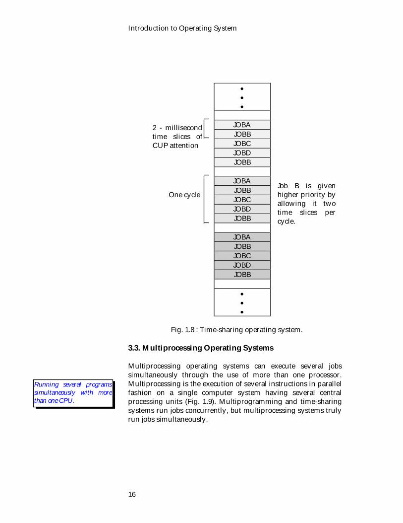
Fig. 1.8 : Time-sharing operating system. 3.3. Multiprocessing Operating Systems Multiprocessing operating systems can execute several jobs simultaneously through the use of more than one processor. Multiprocessing is the execution of several instructions in parallel fashion on a single computer system having several central processing units (Fig. 1.9). Multiprogramming and time-sharing systems run jobs concurrently, but multiprocessing systems truly run jobs simultaneously.
2 - millisecond time slices of CUP attention
One cycle Job B is given higher priority by allowing it two time slices per cycle.
Running several programs simultaneously with more than one CPU.

Operating System
17
Multiprocessing systems can be subdivided into four general types, all of which have more than one processor; they are briefly described below.
Homogeneous Multiprocessors : These systems make use of multiple identical CPUs. The operating systems coordinates the use of storage by the CPUs so that no unresolved conflicts occur. Homogeneous multiprocessors are commonly used in general-purpose mainframe computers used for business applications of data processing.
Nonhomogeneous Multiprocessors : These systems make use of special-purpose processors in the computing unit, which are actually CPUs in their own right. Nonhomogeneous multiprocessors are found in general-purpose mainframe computers.
Array Processor : This system is composed of a set of identical processors (each is called a processing element, or PE) that are directed and synchronized by a single control unit. They are designed primarily for rapidly manipulating highly ordered sets of data, such as are encountered in scientific and mathematical applications.
Fig. 1.9: Multiprocessing operating system.
Pipeline Processors : In pipeline systems, multiple processors are used to perform different stages of consecutive computer instructions simultaneously. The
Commonmain
storage
CPU 1 CPU 2 CPU 3 CPU 4
Shared input/output channels
Magnetictape
storage
Magnetictape
storage
Videodisplay
termainals
High-speedprinters
Diskstorage
Diskstorage

Introduction to Operating System
18
processors are arranged like a factory production line, allowing several operands to be in different stages of execution at the same time. Like array processor systems, these systems perform calculations very quickly. They are primarily used for scientific and mathematical applications.
1. The main advantage of multiprocessing systems is speed;
since more than one CPU is available, jobs can be processed faster than they can with only one CPU.
2. Multiprocessing systems are high-performance operating systems, implemented almost exclusively on mainframes and supercomputers.
3. In this system CPU will more likely be available when it is requested.
3.4. Exercises
3.4.1. Multiple choice questions 1. Time sharing systems are
i) event driven ii) time driven iii) input driven iv) output driven.
2. Which is true for time sharing operating systems ?
i) Running several programs concurrently. ii) Serving several users concurrently. iii) Running several programs simultaneously with one CPU. iv) None of the above.
3. The multiprocessing operating systems can be subdivided into
i) 2 general types ii) 3 general types iii) 4 general types iv) 5 general types.
3.4.2. Questions for short answers
a) What is the goal of time sharing systems ? .
Advantages

Operating System
19
b) What are the difference between time sharing and multiprogramming systems ?
c) What is a pipeline processor? d) Distinguish between multiprogramming, time sharing and
multiprocessing operating system? e) List some of the advantages of multiprocessing systems?
3.4.3. Analytical questions
a) What do you understand by time-sharing Operating Systems? Describe briefly.
b) What do you know about the multiprocessing operating system?
c) Describe different types of multiprocessing systems.

Introduction to Operating System
20
Lesson 4 : Real-Time and Virtual Storage
Operating System 4.1. Learning Objectives
On completion of this lesson you will be able to :
explain real time operating systems describe different types of real-time operating systems describe virtual storage operating systems and their
implementation.
4.2. Real-time Operating System The processing of information or data in a sufficiently rapid manner so that the results of the processing are available in time to influence the process being monitored or controlled. Real time operating systems control computers that interact with their environments to perform work. There are two major types of real-time operating systems : process control systems and process monitor systems. Process control systems take input data from sensors, analyze them and then cause actions to occur that change the processes that they control. Process monitor systems also take input data from sensors, but they merely report the data without actually affecting the processes that they are monitoring. Both of these types of real-time operating systems are being used for more and more industrial and military applications. Real time operating systems are currently being used for such applications as automated environmental monitoring for air and water pollution, directing and monitoring the flows in a chemical plant, police inquiry system, airline reservation, microscopic assembly processes, medical analysis systems, air and automobile traffic control, factory production, oil pipeline regulation and some display systems.
Controlling or monitoring external processes.
Uses

Operating System
21
Fig. 1.10 : Real time operating system. A real time system is often used as a control device in a dedicated application. Sensors bring data to the computer. The computer must analyze the data and possibly adjust controls to modify the sensor inputs. Real time operating systems have to work within strict time limits for critical jobs or the systems will fail. Critical jobs are locked in memory and receive the highest priority. Real time systems are required to be highly reliable. For example, failure of a system which controls a space vehicle in motion may result in a fatal accident. In such cases, duplicate systems are used so that if one system fails, the other will take over. 4.3. Virtual Storage Operating System Virtual storage is a technique that uses some secondary storage, by employing segmentation and/or paging, to augment primary memory. Virtual storage is a memory management tactic that employs an area of rapidly accessible secondary storage (e.g. a hard disk) as an extension of primary memory. Portions of programs are swapped into real storage (the actual primary memory) from virtual storage as needed. This gives users the illusion that more primary memory is available than is actually the case. Since this memory management is automatically taken care of by the operating system, users are freed from having to worry about how much memory their programs will require. Virtual storage is a memory management tactic of using some secondary storage to augment primary memory. Users don’t have to worry if their programs require more space in memory than is actually available because such systems can give them as much
Memory management to overcome space limitations.
cpuSensor
Control

Introduction to Operating System
22
virtual storage as is needed. Virtual storage is usually implemented by segmentation, paging or a combination of them. 4.3.1. Segmentation Segmentation is the process of dividing up a program that is to be run into a number of chunks (or segments) of different sizes and placing these segments in memory wherever they fit. Segmentation divides programs into pieces of different sizes, which are stored in secondary storage and transferred into primary memory (Fig. 1.11).
Fig. 1.11 : Segmentation. 4.3.2. Paging Paging is similar to segmentation except that programs are divided into equal sized portions. As with segmentation, the operating systems keeps track of page locations by constructing page table. As pages are fixed sizes, the use of paging can result in less waste of real storage space. Since segments can be of different sizes, swapping in new segments from virtual storage can leave little fragments of unused space in real memory. By making all program pieces the same size, paging eliminates this type of waste.
Subroutine A Segment 1
Subroutine B
Segment 2
Subroutine C
Segment 3
Subroutine D
Segment 4
Subroutine B
Segment 2
Segmentstransferred
into realstorage as
needed
PRIMARY STORAGE(real storage)
SECONDARY STORAGE(virtual storage)
Program

Operating System
23
The best memory management scheme is to combine segmentation and paging by first segmenting programs and then further subdividing each segment into pages.
Fig. 1.12 : Paging. 4.4. Exercises 4.4.1. Multiple Choice Questions 1. How many types of real-time operating system are there
in this lesson? i) 2 ii) 3 iii) 4 iv) 5. 2. Which of the following is related to real-time operating
systems? i) Execution of programs concurrently. ii) Controlling or monitoring external processes. iii) Serving several users at a time. iv) None of the above. 4.4.2. Questions for short answers a) List some of the uses of real time operating systems. b) Describe the real time operating system.
Page 1
Page 2 Pages transferredinto real storage
as needed
PRIMARY STORAGE(real storage)
SECONDARY STORAGE(virtual storage)
Program
Page 2
Page 3
Page 4
Page 5
End of program
Unused space in last page

Introduction to Operating System
24
c) What do you understand by segmentation? d) What is paging? e) What are the two types of operating systems? 4.4.3. Analytical questions a) What do you understood by real-time operating systems?
Describe briefly. b) What is process control system and process monitor
system? c) Describe a virtual storage operating system with their
implementation.

Operating System
25
Lesson 5 : Functions and Evaluation of
Operating System 5.1. Learning Objectives On completion of this lesson you will know : major functions of an operating system the evaluation of operating system. 5.2. Functions of Operating Systems An operating system performs support functions. Before the advent of operating system in the early 1960s, computer operators had to perform the support functions that are now done by the operating system. Today, operating systems successfully perform many of the functions previously assigned to operators; further more, modern operating systems perform these functions better, faster and more economically. An operating system provides an environment for the execution of programs. An Operating System has a complex mixture of diversified functions. The specific functions provided will, of course, differ from one operating system to another, but there are some common classes of functions which can be identified. Its major functions are as follows :
Memory Management : Memory management involves monitoring the various storage and retrieval operations in main memory. The operating system keeps track of vital information such as which areas are and are not in use and who is using the memory at any given time. In a large system this task can be very complicated. If virtual memory is being used, for example, portions of main memory are being transferred to and from the disk, and the operating system coordinates this process. Paging and segmentation are two common methods of realizing virtual memory. Another example of complex memory management is multiprogramming, a mode of operation
Memory management
Introduction to Operating System
26
in which two or more computer programs are executed by a single CPU in an interleaved manner. The operating system must then coordinate the memory requirements of the several programs.
CPU Management : On smaller computers, the operating system keeps track of the status of the CPU at any point. It determines, for instance, whether the control unit is in the instruction cycle or the execution cycle. When many users are competing for the CPU, the operating system must prioritize and schedule its use. Larger minicomputers and mainframes often include several CPUs, which are together referred to as a multiprocessor. In multiprocessing (operating a multiprocessor system), CPU management becomes much more complex. The major advantage of multiprocessing, from the user’s standpoint, is that a CPU will more likely be available when it is requested.
Input/output and File Management : The operating system
efficiently and reliably controls many different types of input and output devices, such as keyboards, printers, monitors, and audio inputs. These devices have different specifications in terms of speed, printing density, control mechanism, and other variables. The operating system is also responsible for keeping track of the files and directories that reside on hard or floppy disks.
Management of Communication : The operating system
manages communication among computers connected on a network. Since data exchanged on the network may be received intermittently instead of continuously, they must be combined by the operating system. The received data is then converted into a form that computers can process. The operating system also keeps track of the status of the network, disconnecting faulty portions, reporting computer usage accounts, and so on.
Security : The operating system protects computers from
access by illegal users and from data corruption introduced by unintentional mistakes made by legitimate users. Security is particularly important for computers that are connected to a communications network, because many users can freely access any computer. Authorized users are authenticated by entering an individual
CPU management
I/O and file management
Management of communication
Security
User interface
Operating System
27
password, and then a computer usage fee is charged to the account of each user.
User Interface : The operating system provides a
convenient interface between a computer and its users. In the case of batch processing with mainframes, for example, users may want to run their large program only after midnight for several days until the execution of the programs is completed. In the case of personal computers and workstations, graphical user interfaces such as windows and icons displayed on a monitor are convenient, for users.
Detection of Errors : The operating system constantly needs
to be aware of possible errors that may occur in the CPU and memory hardware (e.g. a memory error or power failure), in I/O devices (e.g. a parity error on tape or the printer out of paper), or in the user program (e.g. an arithmetic overflow, an attempt to access illegal memory location or using too much CPU time). For each type of error, the operating system should take the appropriate action to ensure correct and consistent computing.
Information Management : The operating system also
monitors system information, which is organized into records and files. There are several distinct tasks of information management. These are as follows :
Managing groups of file Managing file directories Processing and managing the records within a file.
Allocation of Resources : If, there are multiple users or
multiple jobs running at the same time, then an operating system must coordinate the use of all available resources. A good operating system accomplishes this in the most efficient manner possible.
Besides these functions, some of the functions provided by a modern operating system is as follows :
Provides for human - computer interaction Boots or starts the computer operations Schedules job
Detection of errors
Information management
Allocation of resources
Functions of modern OS

Introduction to Operating System
28
Manages data and file storage Assigns different task to the CPU Provides security and control.
5.3. Development of Operating System OS have been evolving through the years. In the following sections we will briefly look at this development. The earliest computer systems had no operating systems; users had access to computer resources only via machine language programs. Programs were run one at a time by computer operators who manually entered the commands to initiate and complete each one. This pattern of usage wasted a great deal of computer time, since the CPU remained idle between the completion of one task and the initiation of the next. The 1950s were marked by the development of rudimentary operating systems designed to smooth the transitions between jobs (a job is any program or part of a program that is to be processed as a unit by a computer). This was the start of batch progressing, in which programs to be executed were grouped into batches. While a particular program was running, it had total control of the computer. When it finished, control was returned to the operating system, which handed any necessary finalizations and read in and started up the next job. By letting the computer handle the transition between one job and the next instead of having it done manually, less time we taken up and the CPU was more efficiently utilized. During the 1960s, operating systems became much more sophisticated, leading up to the development of shared system. These multiprogramming, time-sharing and multiprocessing systems (which we have defined and discussed in more detail in the previous lessons) allowed several user programs to be run on a single computer system, seemingly at the same time. Additionally, these systems were the first to allow usage to take place in interactive, or conversational, mode, in which the user communicates directly with the computer, rather than submitting jobs and passively waiting for their completion. These developments made computer systems more widely accessible and easier to use.
History of OS

Operating System
29
Real-time systems also emerged during the 1960s. These operating systems enabled computers to be used to control systems characterized by the need for immediate response, such as weapons systems or industrial plants. For example, if an oil refinery is being controlled by a real-time system, that system must responds immediately to temperature conditions that could cause an explosion. In the late 1960s and the early 1970s, there was a trend toward general-purpose operating systems. These tried to be all things to all users. Often called multi-mode systems, some of them simultaneously supported batch processing, time sharing, real-time processing and multiprocessing. They were large, expensive, and difficult to develop and maintain, but they helped sell a lot of computers. The prime example of this type of operating system was the one offered with the IBM 360 family of computers first introduced in 1964. To get one of these monsters to perform even the simplest task, users had to learn a complex job control language (JCL) and employ it to specify how their programs were to be run and what resources they would need. The operating systems from the mid-1970s to the present cannot be characterized by a single, all-encompassing feature. The development of microcomputers and of simple, easy-to-use, single-user operating system has had a profound effect on the newest systems being developed for all types of computers. The features most in demand are a high degree of user-friendliness and a computing environment that is menu-driven (refers to the user of displays and prompts that aid users in selecting functions). Also, operating systems that support on-line processing, computer networking, data security, and distributed data processing are the latest word. Modern operating systems create a virtual machine, an interface that relieves the user of any need to be concerned about most of the physical details of the computer system or network being accessed. The virtual machine presented by the operating system lets users concentrate on getting done what they need, without having to be familiar with the internal functioning of the actual hardware. 5.4. Different Classes of Computers Most operating system researches and development has been done for mainframes computers. Mainframe operating systems have been developing over the last thirty years.
History of operating system.

Introduction to Operating System
30
In the mid-1960's, minicomputers appeared which are on smaller and less expensive than mainframe system. In the 1970's personal computers appeared which are even smaller and less expensive operating systems. In general, an examination of operating systems for mainframes, minicomputers, and personal computers(PC) shows that features which were at one time available only on mainframes have been adopted by minicomputers. Those on minicomputers have been introduced on PC. The same concepts and techniques are appropriate for all the various different classes of computers. A good example (Fig.1.13) of this migration can be seen by considering the evolution of the Unix from Mutics operating system. Multics was developed from 1965 to 1970 at MIT as a computing utility. It ran on a very large and complex mainframe computer. Many of the ideas which were developed for Multics were subsequently used at Bell Labs in the design of Unix, which has become one of the most popular minicomputer systems around 1970 was offered on many PCs around 1980. Thus the features developed for a large mainframe system can be seen to have moved to PC over time.
1950 1960 1970 1980Multics
Mainframesno
software compilers time-shared
distributedsystemsmulti-user
batchresidentmonitors
Minicomputersno
software
1960 1970 1980compilers
time-shared
multi-user
Unix
Personalcomputers1970 1980
nosoftware
Unix
compilersinteractive
multi-user
residentmonitors
residentmonitors
Operating System
31
Fig. 1.13 : Migration of operating system concepts and features. 5.5. Exercises 5.5.1. Multiple choice questions 1. Which of the following is not the function of an operating
system? i) Memory management ii) CPU management iii) I/O and file management iv) Debugging programs. 2. How many tasks of information management are there in
this lesson? i) 2 ii) 3 iii) 4 iv) None of the above. 5.5.2. Questions for short answers a) List some of the functions of a modern operating system. b) What is major advantage of multiprocessing? c) What are the tasks of information management? d) What do you know about micro-kernel? 5.5.3. Analytical questions a) What are the services provided by an OS? Briefly
describe. b) Write an essay on the history of operating systems.

Introduction to Operating System
32

Unit 2 : Computer and Operating System Structure
Lesson 1 : Interrupts and I/O Structure 1.1. Learning Objectives On completion of this lesson you will know : what interrupt is the causes of occurring interrupt instruction cycle with interrupt I/O structure. 1.2. Interrupts A method by which other events can cause an interruption of the CPU's normal execution. An Interrupt is a method by which the normal operation of the CPU can be changed. Interrupts are a better solution than polling for handling I/O devices. There are many methods to handle interrupts. Four general classes of interrupts are :
Program, trap instructions, page faults etc. Timer I/O devices and Hardware failure.
When an interrupt occurs a register in the CPU will be updated. When the CPU finishes the current execute cycle, and when interrupts are enabled, it will examine the register. If the register indicates that an interrupt has occurred and is enabled the interrupt cycle will begin, Otherwise it will be bypassed. The interrupt cycle will call some form of interrupt handler (usually supplied by the operating system) that will examine the type of interrupt and decide what to do. The interrupt handler will generally call other processes to actually handle the interrupt. The CPU follows the simple program outlined in the following diagram.
An Interrupt is a method by which the normal operation of the CPU can be changed.

Operating System
34
Start
FetchCycle
ExecuteCycle
InterruptCycle
HaltInterruptDisabled
InterruptDisabled
Fig.2.1 : Interrupt cycle with interrupts. Interrupts are disabled when the operating system wishes to execute some code that must not be interrupted. Examples include interrupt handlers, semaphore operations. The following table describes the causes of occurring interrupts:
Table 2.1: The causes of occurring interrupts. Interrupt Type Caused by... Program trap instructions page faults etc.
generated by some condition which is a result of program execution (error condition, system call).
Timer generated by the system timer. I/O generated by I/O controller, signals
completion of I/O task (either success or failure).
Hardware failure power failure, memory parity error.
Simple Interrupt Processing Steps for processing interrupts are shown below where steps 1 to 5 is done by hardware and from 6 to 9 is done by software
1. Interrupt occurs 2. Processor finishes current instruction 3. processor signals acknowledgment of interrupt

Computer and Operating System Structure
35
4. processor pushes program status word (Program Status Word) and program counter (Program Counter) onto stack
5. processor loads new Program Counter value based on interrupt
6. save remainder of process information 7. process interrupt 8. restore process state information 9. restore Program Status Word and Program Counter.
1.3. I/O Structure One of the main functions of an OS is to perform all the computer's I/O devices. It issues commands to the devices, catch interrupts and handle errors. It provide an interface between the devices and the rest of the system. We will discuss the I/O hardware and I/O Software.. 1.3.1. I/O Hardware The I/O hardware is classified as
I/O devices Device controllers and Direct memory access (DMA).
I/O Devices Normally all input and output operations in operating system are done through two types of devices; block oriented devices and character oriented devices. A block oriented device is one in which information is stored and transferred at some fixed block size (usually some multiple of 512 bytes), each one with its own address. The block oriented device can read or write each block independently of all other ones out or expand. The character oriented device is one in which information is transferred via a character stream. It has no block structure. It is not addressable. For example, punched cards, terminals, printers, network interfaces, mouse etc. The above classification scheme is not always true. Some device do not fit in. So, the idea of device driver was introduced. The idea of device driver is to provide a standard interface to all hardware devices. When a program reads or writes a file, OS
Hardware
Devices

Operating System
36
invokes the corresponding driver in a standardized way, telling it what it wants done, thus decoupling the OS from the details of the hardware. Device Controller I/O units consist of mechanical and electronic components. The electronic component is called device controller. It is also called printed circuit card. The operating system deals with the controller. The controller's job is to convert the serial bit stream into a block of bytes and perform any error connection necessary. The controller for a CRT terminal also works as a bit serial device at an equally low level. Each controller has a few registers that are used for communicating with the CPU and these registers are part of the regular memory address space. This is a called memory mapped I/O. IBM PC uses a special address space for I/O with each controller allocated a certain portion of it. The following table shows some examples of the controllers and their I/O addresses.
I/O Controller I/O Address Keyboard 060 - 063 Hard disk 320 - 32F Printer 378 - 37F Floppy disk 3F0 - 3F7
Table 2.2 : Controllers and their addresses. The operating system performs I/O by writing commands into controller's registers. Direct Memory Access DMA (Direct Memory Access) unit is capable of transferring data straight from memory to I/O devices. How DMA Works? First the controller reads the block from the drive serially, bit by bit, until the entire block is in the controller's internal buffer. Next, it computes the checksum to verify that no read errors have occurred. Then the controller causes an interrupt when the
Device controller
Direct memory access

Computer and Operating System Structure
37
operating system starts running, it can read the disk block from the controller's buffer a byte or a word at a time by executing a loop, with each iteration reading one byte or word from a controller device register and storing it in memory. After the controller has read the entire block from the device into its buffer and verified the checksum, it copies the first byte or word into the main memory at the address specified by the DMA memory address. Then it increments the DMA address and decrements the DMA count by the numbers of bytes just transferred. This process is repeated until the DMA count becomes zero, at which time the controller causes an interrupt. 1.3.2. I/O Software Let us discuss I/O software. The key idea is to organize the software as a series of layers with lower ones concerned with hardware and upper ones concerned with the interfaces to the users. These goals can be achieved by structuring the I/O software in four layers.
Interrupt handlers Device drivers Device independent OS software User level software.
Interrupt Handlers The interrupt handlers will call other processes to handle interrupts that should be hidden away, deep in the bowels of the OS. The best way to hide them is to have every process starting an I/O operation block until the I/O has completed and interrupt occurs. Device Drivers We already know, the idea of device driver is a program that is used to control each device. All hardware components of the computer is called devices. We saw that each controller has one/ more device register used to give it commands. The device drivers issue these commands and check that they are carried out properly.
Software
The idea of device driver is a program that is used to control each device.
Operating System
38
Device Independent I/O Software Some of I/O software is device specific and others are device independent. The basic function of the device independent software is to perform the I/O functions that are common to all devices and to provide a uniform interface to the user level software. The functions of device independent software are :
Device naming. Device protection. Buffering. Providing a device independent block size. Error reporting. Allocating ad releasing dedicated devices. Uniform interfacing for the device drivers.
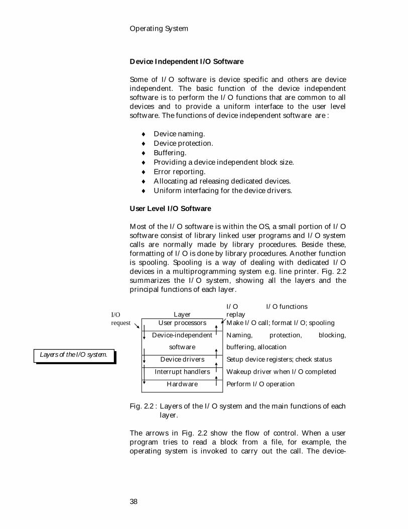
User Level I/O Software Most of the I/O software is within the OS, a small portion of I/O software consist of library linked user programs and I/O system calls are normally made by library procedures. Beside these, formatting of I/O is done by library procedures. Another function is spooling. Spooling is a way of dealing with dedicated I/O devices in a multiprogramming system e.g. line printer. Fig. 2.2 summarizes the I/O system, showing all the layers and the principal functions of each layer.
Layer
I/O I/O functions replay
User processors Make I/O call; format I/O; spooling
Device-independent
software
Naming, protection, blocking,
buffering, allocation
Device drivers Setup device registers; check status
Interrupt handlers Wakeup driver when I/O completed
Hardware Perform I/O operation
Fig. 2.2 : Layers of the I/O system and the main functions of each
layer. The arrows in Fig. 2.2 show the flow of control. When a user program tries to read a block from a file, for example, the operating system is invoked to carry out the call. The device-
Layers of the I/O system.
I/O request
Computer and Operating System Structure
39
independent software looks in the cache, for example. If the needed block is not there, it calls the device driver to issue the request to the hardware. The process is then blocked until the disk operation has been completed. When the disk is finished, the hardware generate an interrupt. The interrupt handler is run to discover what has happened. It then extracts the status from the device, and wakes up the sleeping process to finish off the I/O request and let the user process continue.
1.4. Exercise
1.4.1. Multiple choice questions
1. Normally I/O devices are divided into
i) 2 categories ii) 3 categories iii) 4 categories iv) 5 categories.
2. A device driver is a
i) program ii) controller iii) DMA iv) interrupt handler.
1.4.2. Questions for short answer
a) What are the four classes of interrupts? Provide one example of each class.
b) What do you understood by interrupt? What are the causes of occurring interrupts?
c) Explain why they are important to an operating system. d) What are the functions of the device independent
software? e) List some examples of device controllers. f) What do you mean by memory mapped I/O? g) What do you know about I/O devices?
1.4.3. Analytical questions
a) Describe the layers of the I/O system and list the main functions of each layer.
b) What do you mean by DMA? Explain how it works.

Operating System
40
Lesson 2 : System Calls and System Program
2.1. Learning Objectives On completion of this lesson you will know: system calls categorized system calls and system programs discuss system program. 2.2. System Calls User programs communicate with the operating system and request services from it by making system calls. Fundamental services are handled through the use of system calls. The interface between a running programs and the operating system is defined by what is referred to as systems calls. A system call is a special type of function call that allows user programs to access the services provided by the operation system. A system call will usually generate a trap, a form of software interrupt. The trap will force the machine to switch into the privileged kernel mode-that allows access to data structures and memory of the kernel. In other words, system calls establish a well defined boundary between a running object program and the operating system. When a system call appears in a program, the situation is equivalent to a conventional procedure call whereby control is transferred to operating system routine invoked during the run time along with change of mode from user to supervisor. These calls are generally available as assembly language instructions, and are usually listed in the manuals used by assembly language programmers. System calls can be roughly grouped into three major categories: process or job control, device and file manipulation, and information maintenance. In the following discussion, the types of system calls provided by an operating system are presented. 2.2.1. Process and Job Control A running program needs to be able to halt its execution either normally (end) or abnormally (abort). If the program discovers an error in its input and wants to terminate abnormally.
A system call is a special type of function call that allows user programs to access the services provided by the operation system.
Process and Job Control
Computer and Operating System Structure
41
A process or job executing one program may want to load and execute another program. This allows the control card interpreter to execute a program as directed by the control cards of the user job. If control returns to the existing program when the new program terminates, we must save the memory image of the existing program and effectively have created a mechanism for one program to call another program. If both programs continue concurrently, we have created a new job or process to be multi-programmed. Then system call (create process or submit job) are used. If we create a new job or process, to control its execution, then control requires the ability to determine and reset the attributes of a job or process, including its priority, its maximum allowable execution time, and so on (get process attributes and set process attributes). We may also want to terminate a job or process that we created (terminate process) if we find that it is incorrect or on longer needed. Having created new jobs or processes, we may need to wait for them to finish execution. We may want to wait for a certain amount of time (wait time), but more likely we want to wait for a specific event (wait event). The jobs or processes should then signal when that event has occurred (signal event). 2.2.2. File Manipulation The file system will be discussed in more detail in unit 7. We first need to be able to create and delete files. Once the file is created, we need to open it and use it. We may also read, write, and reposition (rewinding it or skipping to the end of the file). Finally, we need to close the file, indicating that we are no longer using it. We may need these same sets of operations for directories if we have a directory structure in the file system. In addition, for either files or directories, we need to be able to determine the values of various attributes, and perhaps reset them if necessary. File attributes include the file, name a file type, protection codes, accounting information, and so on. Two system calls, get file attribute and set file attribute are required for this function.
File Manipulation
Operating System
42
2.2.3. Device Management Files can be thought of a abstract or virtual devices. Thus many of the system calls for files are also needed for devices. If there are multiple users of the system, we must first request the device, to ensure that we have exclusive use of it. After we are finished with the device, we must release it. Once the device has been requested (and allocated to us), we can read, write, and (possibly) reposition the device, just as with files. 2.2.4. Information Maintenance Many system calls are used transferring information between the user program and the operating system. For example, most systems have a system call to return the current time and date. Other system calls may return information about the system, such as the number of current users, the version number of the operating system, the amount of free memory or disk space, and so on. In addition, the operating system keeps information about all of its jobs and processes, and there are system calls to access this information. Generally, there are also calls to reset it (get process attributes and set process attributes). The following summarizes the types of system calls normally provided by OS. i). Process Control
End, Abort Load Create Process, Terminate Process Get Process Attributes, Set Process Attributes Wait for Time Wait Event, Signal Event.
ii). File Manipulation
Create File, Delete File Open, Close Read, Write, Reposition Get File Attributers, Set File Attributes.
Device Management
Information maintenance

Computer and Operating System Structure
43
iii). Device Manipulation
Request Device, Release Device Read, Write, Reposition Get Device Attributes, Set Device Attributes.
iv). Information Maintenance
Get Time of Date, Set Time or Data Get Data System, Set System Data Get Processes, File or Device Attributes, Set Process, File
Device Attributes. System calls to the operating system are further classified according to the type of call. There are :
Normal Termination Abnormal Termination Status Request Resource Request and I/O Requests.
2.3. System Program An important aspect of a modern system is its collection of systems programs to solve common problems and provide a more convenient environment and execution. Systems programs can be classified into several categories : File Manipulation : These programs create, delete, copy, rename, print, dump, list, and generally manipulate files and directories. Status Information : Some programs simply ask the operating system for the date, time, amount of available memory or disk space, number of users, or similar status information. File Modification : Several text editors may be available to create and modify the content of files stored on disk or tape. Programming Language Support : Compilers, assemblers, and interpreters for common programming languages (such as Fortran, Cobol, Pascal, Basic, and so on) are often provided with
System program

Operating System
44
the operating system. But recently many of these programs are being priced and provided separately. Program Loading and Execution : Once a program is assembled or compiled, it must be loaded into memory to be executed. Application Program : Most operating systems come with programs which are useful to solve some particularly common problems, such as compiler-compilers, text formatters, plotting packages, database systems, statistical analysis packages, and so on. The most important system program for an OS is its command interpreter. It is that program which is runs when a job initially starts or user first logs in to a time sharing system. The view of the operating system seen by most users is thus defined by its systems programs, not by its actual system calls. Consequently, this view may be quite removed from the actual system. The problems of designing a useful and friendly user interface are many, but they are not direct functions of the operating system. 2.4. Exercise 2.4.1. Multiple choice questions 1. System calls provide the interface between i) a running program and user ii) a running program and programmer iii) a running program and the OS iv) user and hardware. 2.4.2. Questions for short answers a) What do you understood by system calls? b) How many types of system calls are there in this lesson? c) Summarize the system calls provided by OS? 2.4.3. Analytical questions a) What do you know about system programs? b) Describe different categories of system programs.

Computer and Operating System Structure
45
Lesson 3 : Operating System Structure 3.1. Learning Objectives On completion of this lesson you will know : different types of OS system structure how a system call can be made micro kernel. 3.2. Operating System Structure A number of approaches can be taken for configuring the components of an operating system, ranging from a monolithic to a virtual machines. To conclude the introduction, we identify several of the approaches that have been used to build OS. There are four different structures of operating system, but in this lesson we will discuss only three of them. 3.2.1. Monolithic System The monolithic organization does not attempt to implement the various functions process, file, device and memory management in distinct modules. Instead, all function are implemented within a single module that contains all system routines or process and all operating system data structure. The operating system is written as a collection of procedures, each can call any of the other ones whenever it needs to. When this technique is used, each procedure in the system has a well defined interface in terms of parameters and results, and each one is free to call any other one, if the latter provides some useful computation that the former needs. In monolithic systems, it is possible to have at least a little structure. The services (system calls) provided by the operating system are requested by putting the parameters in well-defined places, such as in registers or on the stack, and then executing a special trap instruction known as a kernel call or supervisor call. This instruction switches the machine from user mode to kernel mode (also known as supervisor mode), and transfers control to the operating system, shown as event 1 in Fig. 2.3. Most CPUs have two modes; kernel mode, for the operating system, in which
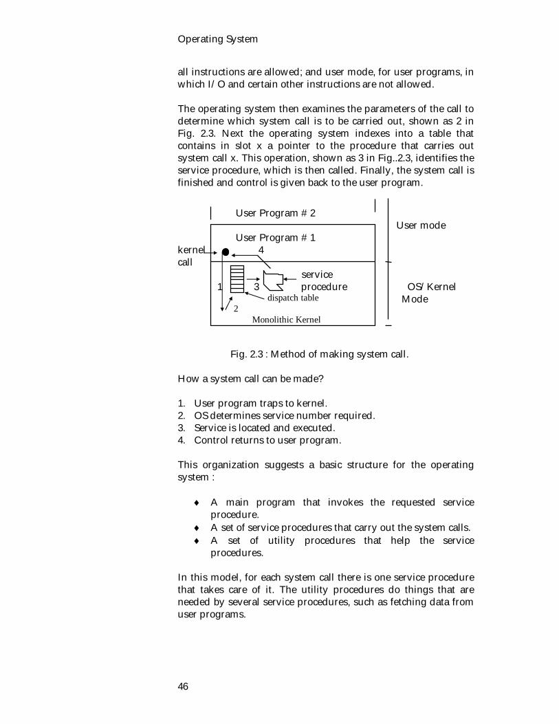
Operating System
46
all instructions are allowed; and user mode, for user programs, in which I/O and certain other instructions are not allowed. The operating system then examines the parameters of the call to determine which system call is to be carried out, shown as 2 in Fig. 2.3. Next the operating system indexes into a table that contains in slot x a pointer to the procedure that carries out system call x. This operation, shown as 3 in Fig..2.3, identifies the service procedure, which is then called. Finally, the system call is finished and control is given back to the user program. User Program # 2 User mode User Program # 1 kernel 4 call service 1 3 procedure OS/Kernel Mode Fig. 2.3 : Method of making system call. How a system call can be made? 1. User program traps to kernel. 2. OS determines service number required. 3. Service is located and executed. 4. Control returns to user program. This organization suggests a basic structure for the operating system :
A main program that invokes the requested service procedure.
A set of service procedures that carry out the system calls. A set of utility procedures that help the service
procedures. In this model, for each system call there is one service procedure that takes care of it. The utility procedures do things that are needed by several service procedures, such as fetching data from user programs.
dispatch table 2
Monolithic Kernel

Computer and Operating System Structure
47
3.2.2. Client / Server or Micro-Kernel Approach A micro-kernel is a "new" way of structuring an operating system. Instead of providing all operating system services (as do most current kernels) a micro-kernel provides a much smaller subset. Services usually provided are memory management, CPU management and communication primitives. Typically a micro-kernel will provide the mechanisms to perform these duties rather than the policy of how they should be used. Other operating system services are moved into user level processes that use the communication primitives of the micro-kernel to share information. In this system, the OS responsibilities are separated out into separate programs. The kernel is stripped of much of its functionality, and basically only provides communication between clients and server. The following Fig. 2.4 will clearly illustrates client server model.
Client Client Process server
Terminal server
File Server
user mode
Kernel
kernel mode
Fig. 2.4 : Client server model. The advantages of this structure is as follows :
better way to write software easier to distribute across many machines.
The main disadvantage is the slow in speed. Difference between monolithic and micro kernel system A monolithic operating system contains all the necessary code in the one kernel. This means that if any changes are made to the kernel the whole system must be rebooted for the changes to take effect.
Clients obtains service by sending messages to server processes.
Advantages and disadvantage.
Operating System
48
A micro-kernel operating system contains a much reduced set of code in the kernel of the operating system. Most of the service provided by the OS are moved out into separate user level processes. All communication within a micro-kernel is generally via message passing whereas a monolithic kernel relies on variables and local procedure calls. These attributes of a micro-kernel mean :
that it is easier to develop the user level parts of the micro-kernel as they can be built on top of a fully working operating system using programming tools,
the user level processes can be recompiled and installed without rebooting the machine,
different service can be moved to totally different machines due to the message passing nature of communication in s micro-kernel operating system.
3.2.3. Virtual Machine In the following discussion we will discuss the structure of a virtual machine named VM/370 with CMS expand. The first releases of OS/360 were batch systems. Many 360 users wanted to have timesharing, so various groups, decided to write timesharing systems for it. The official IBM timesharing system, TSS/360 was delivered late and was eventually abandoned.
Virtual 370s
System calls here
I/O instructions here CMS CMS CMS trap here trap here VM/370
370 Bare hardware Fig. 2.5 : The structure of VM/370 with CMS. The next system was called CP/CMS and now called VM/370. The virtual machine monitor, runs on the bare hardware and does the multiprogramming, providing several machines to the next layer up, as shown in Fig. 2.5. Unlike all other operating systems, these virtual machines are not extended machines, but they are exact copies of the bare hardware, including kernel/user mode,
Computer and Operating System Structure
49
I/O, interrupts, and everything else the real machine has. Each virtual machine is identical to the true hardware, each one can run any operating system that will run directly on the hardware. Different virtual machines can run different operating systems. Some run one of the descendants of OS/360 for batch processing, while other ones run a single-user, interactive system called CMS (Conversational Monitor System) for timesharing users. When a CMS program executes a system call, the call is trapped to the operating system in its own virtual machine, not to VM/370 just as it would if it were running on a real machine instead of a virtual one. CMS then issues the normal hardware I/O instructions for reading its virtual disk. These I/O instructions are trapped by VM/370, which then performs them as part of its simulation of the real hardware. By making a complete separation of the functions of multiprogramming and providing an extended machine, each of the pieces can be much simpler, more flexible, and easier to maintain.
3.3. Exercise
3.3.1. Multiple choice questions
1. Most CPUs have two modes
i) kernel mode and monolithic mode ii) kernel mode and supervisor mode iii) kernel mode and user mode iv) None of the above.
2. CMS stands for
i) computer mail system. ii) conversational monitor system. iii) computer message system. iv) computer mail system.
3.3.2. Questions for short answers
a) What is a micro-kernel? b) Explain the differences between a monolithic operating
system and one based on a micro-kernel architecture. c) How a system call can be made? d) What are the advantages and disadvantages of micro-
kernel system?
3.3.3. Analytical questions
a) What do you know about virtual machine? Describe briefly.

Operating System
50
Unit 3 : Process Management Processes are the most widely used units of computation in programming and systems, although object and threads are becoming more prominent in contemporary systems. Process management and CPU scheduling is the basis of multiprogramming operating system. By switching the CPU between processes the operating system can make the computer more productive. In this unit we will discuss the details of process and scheduling concepts. The concepts of semaphores, process synchronization, mutual exclusion and concurrency are all central to the study of operating systems and to the field of computing in general. The lessons 6 and 7 focuses on these. The lesson 8 of this unit focuses on IPC through message passing and classical IPC problem. Lesson 1 : Process Concept 1.1. Learning Objectives On completion of this lesson you will know : multiprogramming process and process state PCM. 1.2. Multiprogramming and its Problem Multiprogramming is where multiple processes are in the process of being executed. Only one process is ever actually running on the CPU. The remaining process are in a number of others states including. blocked, Waiting for some event to occur, this includes some form of I/O to complete. ready, Able to be executed just waiting on the ready queue for its turn on the CPU.

Operating System
52
The important part of multiprogramming is the execution is interleaved with I/O. This makes it possible for one process to be executing on the CPU and for other processes to be performing some form of I/O operator. This provides more efficient use of all of the resources available to the operating system. Problems involved with multiprogramming are described below resource management Multiple processes must share a limited number of resources including the CPU, memory, I/O devices etc. These resources must be allocated in a safe, efficient and fair manner. This can be difficult and provides more overhead. protection Processes must be prevented from accessing each others resources. mutual exclusion and critical sections there are times when a process must be assured that it is the only process using some resource extra overhead for the operating system The OS is responsible for performing all of these tasks. These tasks require additional code to be written and then executed. Benefits The benefits of multiprogramming are increased CPU utilization and higher total job throughput. Throughput is the amount of work accomplished in a given time interval. 1.3. Process A process is defined as an instance of a program in execution. A process is a sequential unit of computation. The action of the unit of computation is described by a set of instructions executed sequentially on a Von-Neuman computer, using a set of data associated with the process. The components of a process are the programs to be excepted. The data on which the program will execute, resources required by the program (e.g. memory) and the status of the execution. For the process to execute; it must have a suitable abstract machine environment. In various operating systems, processes may be called jobs, users, programs, tasks or activities. A process may be considered as a job or time shared program.
Problems
Benefits
A process is defined as an instances of a program in execution.

Process Management
53
1.3.1. Process State As the program executes, the process changes state. The state of a process is defined by its current activity. Process execution is an alternating sequence of CPU and I/O bursts; beginning and ending with a CPU burst. Thus each process may in one of the following states; new, ready, running, blocked or halted. A process which is waiting for the CPU is ready. A process which has been allocated the CPU is running. A process which is wanting for some thing to occur is blocked. Some systems may add a suspended state. Processes will become suspended when the operating system decides that too many processes are on the system. In an attempt to lighten the load the processes will be suspended. Most of their resources will be released. At some later time when the system load has been reduced the operating system may change the processes state back.
Fig. 3.1 : Process state diagram. Reasons for Transition
1. Operating system places process onto CPU. 2. Process has to wait for some event to occur.
a) Some form of I/O. b) an interrupt must be handled.
3. The event of the process was waiting on has occurred. 4. The processes quantum has expired. 5. The process finishes execution.
New Ready Running Halted
Blocked
Program Execution
1
4
32
5
The state of a process is defined by its current activity.

Operating System
54
1.3.2. CPU-I/O Burst Cycle The success of CPU scheduling depends upon the following observed property of processes : CPU burst and I/O burst. Process execution is a cycle of CPU execution and I/O wait. Processes alternate back and forth between these two states. Process execution begins with a CPU burst. It is followed by an I/O burst, which is followed by another CPU burst, then another I/O burst, and so on. Eventually, the last CPU burst will end with a system request to terminate execution, rather than another I/O burst (Fig. 3.2). LOAD STORE SUB STORE LOAD from file
wait for I/O STORE INCREMENT INDEX WRITE to file
wait for I/O
Fig. 3.2 : Sequence of CPU and I/O bursts. The duration's of these CPU bursts have been measured. Although they vary greatly from process to process and computer to computer. There are a very large number of very short CPU bursts and a small number of very long ones. An I/O-bound program might have a few very long CPU bursts. It is important to select appropriate CPU scheduling algorithm. 1.3.3. Process Control Block The operating system groups all information that it needs about a particular process into a data structure called a process descriptor or a process control block (PCB). Whenever a process is created (initialized, installed), the operating system creates a corresponding process control block to serve as its run-time description during the lifetime of the process. When the process terminates, its PCB is released to the pool of free cells from which new PCBs are drawn. A Process becomes known to the operating
I/O burst
CPU burst
I/O burst
CPU burst
A process control block (PCB) is a data block or record containing many pieces of the information associated with a specific process.

Process Management
55
system and thus eligible to compete for system resources only when it has an active PCB associated with it. Each process is represented in the operating system by its own process control block (also called a tack control block or a job control block). A process control block (PCB) is a data block or record containing many pieces of the information associated with a specific process. The information stored in PCB typically includes.
Process ID /Number The process state may be new ready, running, or halted. The program counter indicates the address of the next
instruction to be executed for this process. The CPU registers Any memory management information, including base
and bounds registers or page tables. Any accounting information, including the amount of
CPU and real time used, time limits, account numbers, job or process numbers, and so on.
I/O status information CPU scheduling information, including a process priority,
pointers to scheduling queues, and any other scheduling parameters.
The PCB simply serves as the repository for any information that may vary from process to process.
Operating System
56
1.4. Exercise 1.4.1. Multiple choice questions 1. Which of the following process state transition is invalid? i) ready running ii) ready blocked iii) blocked ready iv) running dead. 1.4.2. Questions for short answers 1. Multiprogramming i) Why it is used? ii) What problems does using it produce? iii) What benefits does using it produce? 2. Describe the life cycle of a process? 3. What possible states are involved? 4. What are reasons for a transition from one states to
another? 1.4.3. Analytical questions a) What do you understand by PCB? Briefly describe. b) What are the components of a processor?

Process Management
57
Lesson 2 : Scheduling Concept 2.1. Learning Objectives On completion of the lesson you will be able to know : scheduling and scheduling queues what a scheduler is different types of schedulers. Scheduling is a fundamental operating system function, since almost all computer resources are scheduled before use. The CPU is of course, one of the primary computer resources. Thus its scheduling is central to operating system design. When more than one process is run-able, the OS must decide which one to run first. That part of the OS concerned with this decision is called scheduler and the algorithm it uses is called scheduling algorithm. Scheduling refers to a set of policies and mechanism into operating system that govern the order in which the work to be done by a computer system is complicated. Scheduler is an OS module that selects the next job to be admitted into the system and the next process to run. The primary objective of scheduling is to optimize system performance in accordance with the criteria deemed most important by the system designer. Before discussing about schedulers, we have to know about scheduling queues. Let's look at scheduling queues. 2.2.1. Scheduling Queues The ready queues is used to contain all processes that are ready to be placed on to the CPU. The processes which are ready and waiting to execute are kept on a list called the ready queue. This list is generally a linked list. A ready queue header will contain pointers to the first and last PCBs in the list. Each PCB has a pointer field which points to the next process in the ready queue.
Scheduling
Scheduler

Operating System
58
Fig. 3.3 : The ready queue. The ready queue is not necessarily a first-in-first-out (FIFO) queue. A ready queue may be implemented as a FIFO queue, a priority queue, a tree, a stack, or simply an unordered list. Conceptually, however, all of the processes in the ready are lined up waiting for a chance to run on the CPU. The list of processes waiting for a particular I/O device is called a device queue. Each device has its own device queue. If the device is a dedicated device, the device queue will never have more than one process in it. If the device is sharable, several processes may be in the device queue. A common representation for a discussion of CPU scheduling is a queuing diagram such as Fig. 3.3. Each rectangular box represents a queue. Two types of queues are present : the ready queue and a set of device queues. The circles represent the resources which serve the queues, and the arrows indicate the flow of processes in the system. A process enters the system from the outside world and is put in the ready queue. It waits in the ready queue until it is selected for the CPU. After running on the CPU, it waits for an I/O operation by moving to an I/O queue. Eventually, it is served by the I/O device and returns to the ready queue. A process continue this CPU-I/O cycle until it finishes; then it exits from the system.
Ready Queue CPU I/O I/O Queue I/O I/O Queue . . . . I/O I/O Queue

Process Management
59
Since our main concern at this time is CPU scheduling, we can replace with one I/O waiting queue and I/O server. 2.2.2. Types of Schedulers In general, there are three different types of schedulers, which may coexist in a complex operating system : long-term, medium-term, and short-term schedulers. Fig. 3.4 shows the possible traversal paths of jobs and programs through the components and queues, depicted by rectangles, of a computer system. The primary places of action of the three types of schedulers are marked with down-arrows. As shown in Fig. 3.4, a submitted batch job joins the batch queue while waiting to be processed by the long-term scheduler. Once scheduled for execution, processes spawned by the job enter the ready queue to await processor allocation by the short-term scheduler. After becoming suspended, the running process may be removed from memory and swapped out to secondary storage. Such processes are subsequently admitted to main memory by the medium-term scheduler in order to be considered for execution by the short-term scheduler.
Fig. 3.4 : Schedulers. Long-term scheduler The long-term scheduler (or job scheduler) works with the batch queue and determines which jobs are admitted to the system for processing. In a batch system, there are often more jobs submitted than can be executed immediately. These jobs are spooled to a mass storage device (typically a disk), where they are kept for
Long Term scheduling : The decision to add to the pool of processes to be executed.
Batch Queue ReadyQueue
I/O waitingQueue
Suspended &Swappedout
Queue
CPU
CPU
Long-termScheduler
Short-termScheduler
Medium-termScheduler
Exit
Batch Jobs

Operating System
60
later execution. The long-term scheduler selects jobs from this job pool and loads them into memory for execution. The primary objective of the long-term scheduler is to provide a balanced mix of jobs, such as CPU bound and I/O bound, to the short-term scheduler. In a way, the long-term scheduler acts as a first-level throttle in keeping resource utilization of the desired level. Short-term scheduler The short-term scheduler (or CPU scheduler) selects from among the jobs in memory which are ready to execute and allocates the CPU to one of them. Distinction between long-term and short-term schedulers The primary distinction between these two schedulers is the frequency of their execution. The short-term scheduler must select a new process for the CPU quite often. A process may execute only a few milliseconds before waiting for an I/O request. Often the short-term scheduler executes at least once every 10 milliseconds. Because of the short duration between executions, the short-term scheduler must be very fast. The long-term scheduler, on the other hand, executes much less frequently. It may be minutes between the arrival of new jobs in the system. The long-term scheduler controls the degree of multiprogramming (the number of processes in memory). Medium-term scheduler The key idea behind a medium-term scheduler is that it can sometimes be advantageous to remove processes from memory (and from active contention for the CPU) and thus reduce the degree of multiprogramming. At some later time, the process can be reintroduced into memory and continued where it left off. This scheme is often called swapping. The process is swapped out and swapped in later by the medium-term scheduler. Swapping may be necessary to improve the job mix, or because a change in memory requirements has over committed available memory, requiring memory to be freed up.
Short term scheduling : The decision as to which process will gain the processor.
Medium term scheduling : The decision to add to the process in main memory.
Process Management
61
Dispatcher Another component involved in the CPU scheduler function is the dispatcher. The dispatcher is the module that actually gives control of the CPU to the process selected by the short-term scheduler. This function involves loading the registers of the process, switching to user mode, and jumping to the proper location in the user program to restart it. Obviously, the dispatcher should be as fast as possible. 2.3. Exercise 2.3.1. Multiple choice question 1. The primary distinction between short term and long term
scheduler is i) the frequency of their execution. ii) time iii) speed iv) number of throughput. 2.3.2. Questions for short answers a) How many types of scheduling queues are there in this
lesson? Describe briefly. b) What do you understand by scheduling and scheduler? c) What do you know about dispatcher? 2.3.3. Analytical questions a) What do you understand by schedulers? Describe
different type of schedulers. b) Distinguish between short term, medium term and long
term scheduling.

Operating System
62
Lesson 3 : Scheduling Criteria and Algorithms
3.1. Learning Objectives On completion of this lesson you will know : scheduling criteria of algorithms the criteria and aim important factors of scheduling mechanism preemptive and non-preemptive scheduling FCFS and shortest job first algorithms. 3.2. Scheduling Criteria CPU scheduling deals with the problem of deciding which of the processes in the ready queue is to be allocated the CPU. Before we look at algorithms for scheduling the CPU, we must first look at the criteria which might make a "good' scheduling algorithm. Many of the following criteria are contradictory. The criteria fall into the following categories.
user-oriented to system-oriented criteria performance or there criteria.
User- Oriented, Performance Criteria Criteria Aim Response Time (the amount of time it takes to start responding).
low response time, maximum number of interactive users.
Turnaround Time (The time between submission & completion)
minimize turnaround time.
Deadlines maximize deadlines met.
Waiting time (the amount of time a job spends waiting in the ready queue).
low waiting time.

Process Management
63
User-Oriented, Other Criteria Criteria Aim Predictability same cost and time usage no matter when a
process is run. System-Oriented, Performance Criteria Criteria Aim Throughput (the number of jobs which are completed per time unit).
allow maximum number of jobs of complete.
Processor Utilization
maximize percentage of time, keep processor as busy as possible.
Overhead minimize time processor busy executing OS.
System Oriented, Other Criteria Criteria Aim Fairness treat processes the same avoid starvation. Enforcing Priorities
give preference to higher priority processes.
Balancing Resources
keep the system resources busy.
Important Factors Factors which affect a scheduling mechanism are :
I/O boundedness of a process CPU boundedness of a process is the process interactive or batch process priority page fault frequency preemption frequency execution time received execution time required to complete.
3.3. Non-preemptive VS Preemptive Scheduling In general, scheduling algorithm may preemptive or non preemptive.

Operating System
64
Preemptive scheduling is useful in a situation where you have high priority processes.
In batch, non-preemption implies that, once scheduled, a selected job runs to completion. With short-term scheduling, on preemption implies that the running process retains ownership of allocated resources, including the processor, until it voluntarily surrenders control to the operating system. In other words, the running process is not forced to relinquish ownership of the processor when a higher-priority process becomes ready for execution. However, when the running process becomes suspended as a result of its own action, say, by waiting for an I/O completion, another ready process may be scheduled. With preemptive scheduling a running process may be replaced by a higher-priority process at any time. This is accomplished by activating the scheduler whenever an event that changes the state of the system is detected. Since such preemption generally necessitates more frequent execution of the scheduler. 3.4. Scheduling Algorithm There are different types of scheduling algorithm. In this lesson, we will describe only about FCFS and SJF, the rest of the algorithm will be discussed in the following lesson. 3.4.1. First-come First Served (FCFS) First-Come First-Served (FCFS) is by far the simplest CPU scheduling algorithm. The work load is simply processed in the order of arrival, with no preemption. The process which request the CPU first is allocated the CPU first. Implementation The implementation of FCFS is easily managed with a FIFO (First in-First out) queue. As the process becomes ready, it joins the ready queue when the current process finishes, the oldest process is selected next. Characteristics
Simple to implement Non-preemptive Penalize short and I/O bound process.
A scheduling algorithm is non-preemptive if the CPU cannot be taken away by the OS.
A scheduling algorithm is Preemptive if the CPU can be taken away by the OS.

Process Management
65
Example Considering the following example, FCFS will be clear to learners.
Job Arrival Time Service time 1 2 3 4 5
1 2 3 4 5
8 2 1 2 5
If the jobs arrive in the above order and are served in FIFS order, we get the result shown in the following Gantt chart. Job 1 Job 2 Job 3 Job 4 Job 5 1 9 11 12 14 19
From the Chart we can get the following Table :
Job
Time Arrive
Time Finish
Time Waiting
Turnaround Time
1 1 9 0 8 2 2 11 7 9 3 3 12 8 9 4 4 14 8 10 5 5 19 9 14
For easy calculation, we have to know the following term : Turnaround time = Time _ Finish - time _arrive. Wait time = Starting execution of the respective job- arriving time of the respective job. So, the average turnaround time of process
= ( )8 9 9 10 14
5505
10
Average wait time = 0 7 8 8 9
5
= 32/5 = 6.4.
There is a convoy effect as all other processes wait for one big process to get off the CPU. This effect results in lower CPU and
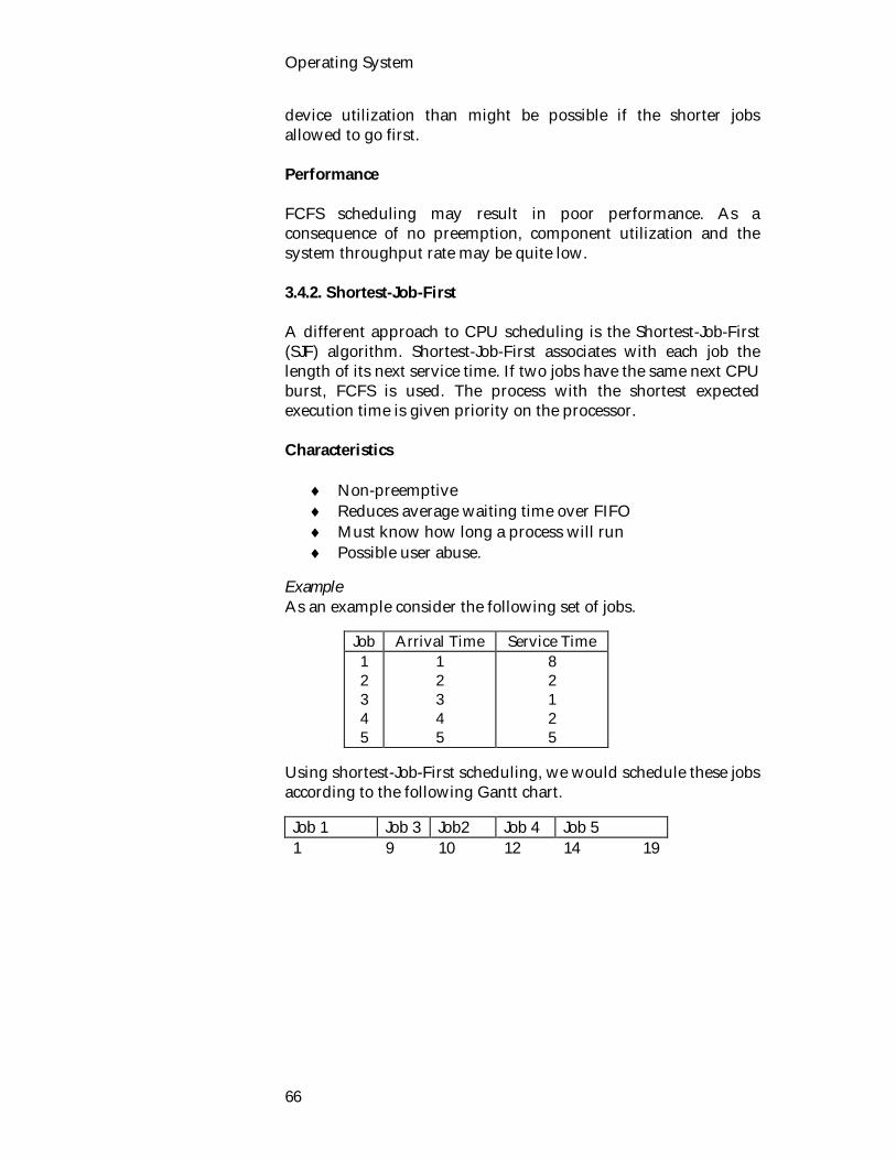
Operating System
66
device utilization than might be possible if the shorter jobs allowed to go first. Performance FCFS scheduling may result in poor performance. As a consequence of no preemption, component utilization and the system throughput rate may be quite low. 3.4.2. Shortest-Job-First A different approach to CPU scheduling is the Shortest-Job-First (SJF) algorithm. Shortest-Job-First associates with each job the length of its next service time. If two jobs have the same next CPU burst, FCFS is used. The process with the shortest expected execution time is given priority on the processor. Characteristics
Non-preemptive Reduces average waiting time over FIFO Must know how long a process will run Possible user abuse.
Example As an example consider the following set of jobs.
Job Arrival Time Service Time 1 2 3 4 5
1 2 3 4 5
8 2 1 2 5
Using shortest-Job-First scheduling, we would schedule these jobs according to the following Gantt chart.
Job 1 Job 3 Job2 Job 4 Job 5 1 9 10 12 14 19

Process Management
67
From the Chart we can get the following Table :
Job
Time Arrive
Time Finish
Time Waiting
Turnaround Time
1 1 9 0 8 (9-1) 2 2 12 8 (10-2) 10 (12-2) 3 3 10 6 (9-3) 7 (10-3) 4 4 14 8 (12-4) 10 (14-4) 5 5 19 9 (14-5) 14 (19-5)
i) Average turnaround time = 8 10 7 10 14
59 8
.
ii) Average wait time = (0+8+6+8+9) /5 = 6..2 Shortest Job first is probably optimal, in that it gives the minimum average waiting time for a given set of jobs. The proof in Fig. 3.5 shows that moving a short job before a long one decreases the waiting time of the short job more than it increases the waiting time of the long job. So, the average waiting time decreases.
long short short long
Fig.3.5 : Proving the SJF is optimal.
3.5. Exercises 3.5.1. Multiple choice questions 1. The SJF algorithm is a
i) preemptive CPU scheduling algorithm. ii) disk scheduling algorithm. iii) modification of the RR CPU scheduling algorithm. iv) non-preemptive CPU scheduling algorithm. 3.5.2. Questions for short answers a) What are the performance criteria of a scheduling
algorithm? b) Write short note on : Throughput, Wait time, Turnaround
time, Response time. c) What are the important factors of scheduling mechanism?

Operating System
68
d) What do you understood by preemptive and non-preemptive scheduling.
e) What are the characteristics of FCFS and SJF algorithms? How can they be implemented?
3.5.3. Analytical questions
1) Given the following information
Job Arrival Time Service Time 1 2 3 4 5
0 1 2 3 4
16 2 3 1 5
a) Using FCFS i) Give a Gantt chart illustrating the execution of these jobs. ii) What is the Turnaround time of job 3 ? iii) What is the average turnaround time and wait time for all
the jobs. b) Using SJF i) Give a Gantt chart illustrating the execution of these jobs. ii) What is the Turnaround time of job 3? iii) What is the average turnaround time and wait time for all
the jobs c) Complete the following table for each of the following
scheduling algorithm
Job Finish time 1 2 3 4 5
i) FCFS ii) SJF.
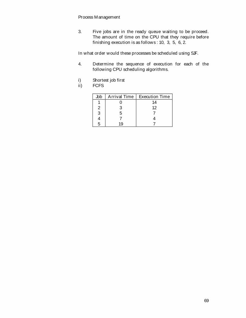
Process Management
69
3. Five jobs are in the ready queue waiting to be proceed. The amount of time on the CPU that they require before finishing execution is as follows : 10, 3, 5, 6, 2.
In what order would these processes be scheduled using SJF. 4. Determine the sequence of execution for each of the
following CPU scheduling algorithms. i) Shortest job first ii) FCFS
Job Arrival Time Execution Time 1 2 3 4 5
0 3 5 7 19
14 12 7 4 7
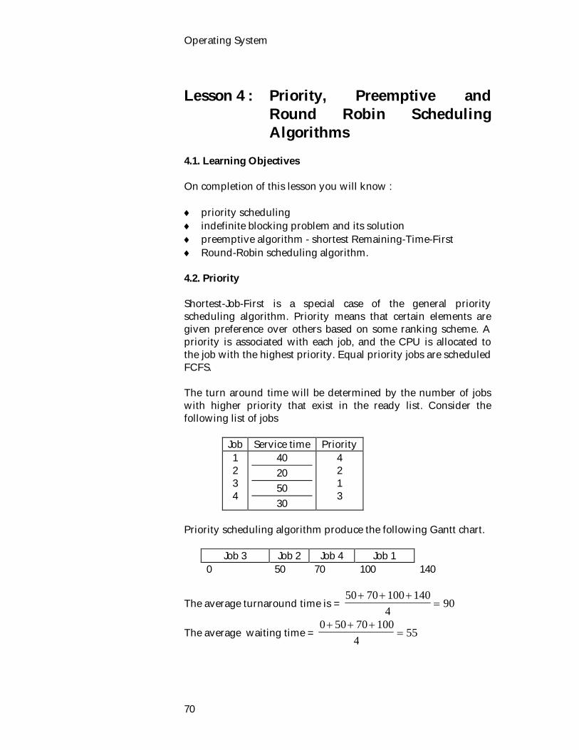
Operating System
70
Lesson 4 : Priority, Preemptive and
Round Robin Scheduling Algorithms
4.1. Learning Objectives On completion of this lesson you will know : priority scheduling indefinite blocking problem and its solution preemptive algorithm - shortest Remaining-Time-First Round-Robin scheduling algorithm. 4.2. Priority Shortest-Job-First is a special case of the general priority scheduling algorithm. Priority means that certain elements are given preference over others based on some ranking scheme. A priority is associated with each job, and the CPU is allocated to the job with the highest priority. Equal priority jobs are scheduled FCFS. The turn around time will be determined by the number of jobs with higher priority that exist in the ready list. Consider the following list of jobs
Job Service time Priority 1 2 3 4
40 20 50 30
4 2 1 3
Priority scheduling algorithm produce the following Gantt chart.
Job 3 Job 2 Job 4 Job 1 0 50 70 100 140
The average turnaround time is = 50 70 100 140
490
The average waiting time = 0 50 70 100
455

Process Management
71
A major problem with priority scheduling algorithms is indefinite blocking or starvation. A process which is ready to run but lacking the CPU can be considered blocked, waiting for the CPU. A priority scheduling algorithm can leave some low-priority processes, waiting indefinitely for the CPU. Starvation results from the ranking scheme having a problem that means one or more elements are continually overlooked and other elements are given preference. They are indefinitely postponed or suffer from starvation when they are never the highest ranking element. A solution to the problem of indefinite of low-priority jobs is aging. Aging is a technique of gradually increasing the priority of jobs that wait in the system for a long time. 4.3. Preemptive Algorithms FCFS, Shortest-Job-First, and priority and priority algorithms, are non-preemptive scheduling algorithms. A process, it can keep the CPU until it wants to release it, either by terminating or by requesting I/O. FCFS is intrinsically non-preemptive, but the other two can be modified to be preemptive algorithms. Shortest-Job-First may be either preemptive or non-preemptive. A preemptive shortest-Job-First algorithm will preempt the currently executing job, while a non-preemptive Shortest-Job-First algorithm will allow the currently running job to finish its CPU burst. Preemptive Shortest-Job-First is sometimes called Shortest-Remaining-Time-First(SRTF). Preemptive is the counterpart of SJF. Implementation Process with the smallest estimated run-time to completion is run next. A running process may be preempted by a new process with a shorter estimate run-time. Characteristics
Preemptive Still requires estimates of the future Higher overhead than SJF Elapsed service times must be recorded Possible starvation.

Operating System
72
Example As an example, consider the following 5 jobs.
Job Arrival Time Burst Time/Service Time 1 2 3 4 5
1 2 3 4 5
8 2 1 2 5
If the jobs at the ready queue at the times shown and need the indicated times, then the following Gantt chart illustrates the resulting preemptive Shortest-Job-First-schedule. preemptive
2
3 4 Job 5 job 1
1 2 4 5 7 12
19
[(19-1) + (4-2) + (5-3) + (7-4) + (12-5)]/5 = 325
= 6.4
Job 1 is started at time 1, since it is the only in the queue. Job 2 arrives at time 2. The remaining time for job 1 (7 time units) is larger then the time required by job 2 (2 time units), so job 1 is preempted, and job 2 is scheduled. The average turnaround time for this example is [(9-1) + (12-2) + (10-3) + (14-4) + (19-5)]/5= 9.8 time units. A non-preemptive Shortest-Job-First scheduling would result in an average turnaround time of 9.8. 4.4. Round-Robin One of the oldest, simplest, fairest and most wide used algorithms is the round-robin (RR) scheduling algorithm, designed especially for time-sharing systems. Characteristics
preemptive effective in time sharing environment

Process Management
73
Penalize I/O bound processes. Quantum Size A small unit of time, called a time quantum or time slice, is defined. A time quantum is generally from 10 to 100 milliseconds. Deciding on the size of quantum is important as it affects the performance of the Round Robin algorithm.
large or small quantum fixed or variable quantum same for everyone or different.
If quantum is to large RR degenerates into RCFS. If quantum is to small context switching becomes the primary job being executed. A good guide is "quantum should be slightly larger than the time required for a typical interaction". Implementation The ready queue is used to contain all those processes that are ready to be placed on the CPU. The ready queue is treated as a circular queue. The CPU scheduler goes around the ready queue, allocating the CPU to each process for a time interval up to a quantum in length. To implement round-robin scheduling, the ready queue is kept as a FIFO queue of processes. New processes are added to the tail of the ready queue. The CPU scheduler picks the first job from the ready queue, sets a timer to interrupt after one time quantum, and dispatches the process. The process that is currently executing on the CPU will continue until either :
its quantum expires

Operating System
74
Each process has a fixed time limit (the quantum) during which they have the CPU and puts it on the operating system takes the process off the CPU and puts it on the end of the ready queue.
it is blocked on some event. The process is awaiting for some event to occur not do any instruction execution until it is finished. The operating system will place the process onto the correct blocked queue. When the waited upon event occurs the process may be put onto either the CPU or the ready queue depending on the specific algorithm used. Example, Consider the four processes shown in following table. The time quantum was 20 with a negligible time for context switching. Then, the Gantt chart describing the resulting schedule is shown in Fig. 3.6 . The average turnaround time for a process is 40 100 130 140
44104
102 5
.
and the average wait time is
60 20 90 100
42704
67 5
.
0 20 40 60 80 100 120 140
1 2 3 4 1 3 4 3
Fig. 3.6 : Round robin schedule for define q = 20. Job 1 gets the first 20 time units. Since it requires another 20, it is preempted after the first time quantum, and the CPU is given to the next job in the queue, job 2. Since job 2 needs 20 units, it quits after its time quantum expires. The CPU is then given to the next process, job 3, but it requires another 30, so it is preempted and CPU is given to the next job in the queue, job 4, but it requires another 10 units, it is preempted, a CPU is returned to job 1 for next time quantum. Then CPU is given to the next job 3, 4 and again job 3 respectively. Advantages of RR: Easy to implement Disadvantage

Process Management
75
Penalize I/O bound process We have problems, specifically, at the end of each time quantum, we get an interrupt from the timer. Processing the interrupt to switch the CPU to another process requires saving all the resisters for the old process and loading the registers for the new process. This task is known as a context switch. Context switch time is pure overhead. So, a context switch is the act of saving the current context on the CPU to memory and then changing the CPU context. The context of the CPU is the collection of CPU registers used to track the status of the current execution. Context switches occur whenever there is an interrupt. To illustrate the effect of context switch time on the performance of round-robin scheduling, let's assume that we have only one job of 8 time units. If the quantum is 10 time units, the job finishes in less than one time quantum, with no overhead. If the quantum is 5 time units, however, the job requires two quanta, resulting in a context switch. If the time quantum is 1 time unit, then 7 context switches will occur, slowing the execution of the job accordingly (Fig. 3.7) .
Job time = 8 Quantum Context Switches
10 0 0 8 5 1 0 5 8 1 7 1 2 3 4 5 6 7 8
Fig. 3.7 : A smaller time quantum increases context switches. 4.5. Exercise 4.5.1. Multiple choice questions 1. Which of the following in not non-preemptive scheduling
algorithm i) First-Come-First-Served
Context Switching
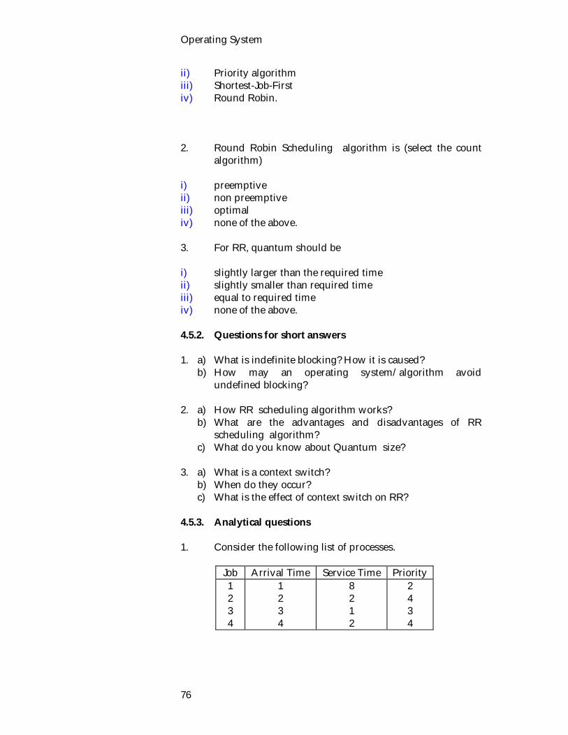
Operating System
76
ii) Priority algorithm iii) Shortest-Job-First iv) Round Robin. 2. Round Robin Scheduling algorithm is (select the count
algorithm) i) preemptive ii) non preemptive iii) optimal iv) none of the above. 3. For RR, quantum should be i) slightly larger than the required time ii) slightly smaller than required time iii) equal to required time iv) none of the above. 4.5.2. Questions for short answers 1. a) What is indefinite blocking? How it is caused? b) How may an operating system/algorithm avoid
undefined blocking? 2. a) How RR scheduling algorithm works? b) What are the advantages and disadvantages of RR
scheduling algorithm? c) What do you know about Quantum size? 3. a) What is a context switch? b) When do they occur? c) What is the effect of context switch on RR? 4.5.3. Analytical questions 1. Consider the following list of processes.
Job Arrival Time Service Time Priority 1 2 3 4
1 2 3 4
8 2 1 2
2 4 3 4
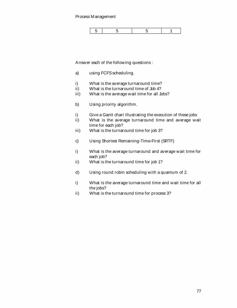
Process Management
77
5 5 5 1 Answer each of the following questions : a) using FCFS scheduling. i) What is the average turnaround time? ii) What is the turnaround time of Job 4? iii) What is the average wait time for all Jobs? b) Using priority algorithm. i) Give a Gantt chart illustrating the execution of these jobs ii) What is the average turnaround time and average wait
time for each job? iii) What is the turnaround time for job 3? c) Using Shortest Remaining-Time-First (SRTF) i) What is the average turnaround and average wait time for
each job? ii) What is the turnaround time for job 1? d) Using round robin scheduling with a quantum of 2. i) What is the average turnaround time and wait time for all
the jobs? ii) What is the turnaround time for process 3?

Operating System
78

Unit 4 : Deadlock Deadlock is a potential problem in any operating system. It occurs when a group of processes each have been granted exclusive access to some resources, and each one wants yet another resource that belongs to another process in the group. All of them are blocked and none will ever run again. Deadlock occurs in many guises in the real world, from processing documents in an office to automobile traffic patterns in large cities. In some cases, deadlock may be purposely defined into a system so that a human operator of the system can intervene to resolve a conflict that is too difficult for the system to solve; this is common in office procedures. In this unit, different methods of handling problems like deadlock modeling, deadlock prevention, deadlock avoidance and deadlock detection will be discussed. Lesson 1 : Introduction to Deadlock 1.1. Learning Objectives On completion of this lesson you will be able to know: deadlock the conditions for deadlock various types of resources an OS manages. 1.2. Resources Before discussing deadlock, we have to know what a resource is. OS is basically a resource manger. Deadlock can occur when processes have exclusive access to devices, files, and so forth. To make the discussion of deadlocks as general as possible, we will refer to the objects granted as resources. A resource can be hardware device (e.g., a tape drive memory) or a piece of information (e.g., a locked record in a database). A computer will normally have many different resources that can be acquired. For some resources, several identical instances may be available, such as three tape drives. When several copies of a resource are available, any one of them can be used to satisfy any request for the resource. In short, a resource is anything that can only be used by a single process at any instant of time.

Operating System
80
Resources come in the following types : Preemptible Resources Resources the OS can remove from a process (before it is completed) and give to another process. Non-preemptible Resources Resources a process must hold from when they are allocated to when they are released. Shared Resource A resource which may be used by many processes simultaneously. Dedicated Resource A resource that belongs to one process only. In general, deadlock involves non-preemptive resources. Under the normal mode of operation, the sequence of events required to use a resource is : 1. Request : If the request cannot be immediately granted (for
example, the resource is being used by another process), then the requesting process must wait until it can acquire the resource.
2. Use : The process can operate on the resource (for example, if
the resource is a line printer, the process can print on the printer).
3. Release : The process releases the resource. A process must request a resource before using it and release the resources after using it. A process may request as many resources as it requires to carry out its designated task. Obviously, the number of resources requested may not exceed the total available in the system. In other words, a process cannot request three printer if the system only has two.

Deadlock
81
1.3. Deadlock Memory is a resource, a tape drive is a resource and access to a shared variable is a resource. Computer systems are full of resources that can only be used by one process at a time Having two processes simultaneously writing to the printer leads to gibberish. All operating systems have the ability to (temporarily) grant a process exclusive access to certain resources. Deadlock problems may be a part of our daily environment. Consider the problem of crossing a river that has a number of stepping stones (Fig. 4.1). At most one foot can be on each stepping stone at a time. To cross the river, a person must use each of the stepping stones. We can view each person crossing the river as a process and each stepping stone as a resource. A deadlock occurs when two people start crossing the river from opposite sides and meet in the middle (Fig. 4.2). Stepping on a stone can be viewed as acquiring the resource, while removing the foot corresponds to releasing the resource. A deadlock occurs when two people try to step on the same stone. The deadlock can be resolved if either person retreats to the side of the river from which they started. In operating system terms, this retreat is called a rollback.
Fig. 4.1 : River crossing. The only way to ensure that a deadlock will not occur is to require each person crossing the river to follow an agreed-upon protocol. One such protocol would require each person who
Any thing that a process needs to proceed as being a resource.

Operating System
82
wants to cross the river to find out whether someone else is crossing from the other side.
Fig. 4.2 : Deadlock situation in river crossing. 1.3.1. Deadlock Definition The deadlock can be defined formally as follows : A set of process is in a deadlock state when every process in the set is waiting for an event that can be caused by another process in the set. The events with which we are mainly concerned here are resource acquisition and release. To illustrate a deadlock state, consider a system with three tape drives. Suppose that there are three processes, each holding one of these tape drives. If each process now requests another tape drive, the three processes will be in a deadlock state. Each is waiting for the event "tape drive is released", which can only be caused by one of the other waiting processes. This example illustrates a deadlock involving processes completing for the same resource type. In other words deadlock is a state where one or more processes are blocked, all waiting on some event that will never occur. For Example, There are two process P1 and P2 and two unshareable resources R1 and R2. Given the following code for process P1 and P2.
P1 P2 lock R1 lock R2 calculate
lock R2 lock R1 calculate
It is possible for the processes to be deadlocked if P1 has locked R1 and P2 has locked R2. Now process one attempts to execute its
Deadlock is a state where one or more processes are blocked, all waiting on some event that will never occur.
Deadlock definition

Deadlock
83
second instruction and obtain a lock on R2. However it must block the only copy of R2 is locked by P2. P2 can now execute and it will attempt to lock R1. However it can't! It must block waiting on P1 to release R1. Neither process can progress until event they are waiting for occurs. P1 is waiting for P2 to release R2 and P2 is waiting for P1 to release R1. Neither event will ever happen. These processes are deadlocked. 1.3.2. Conditions for Deadlock Coffman et. al. (1971) showed that a deadlock situation can arise if and only if the following four conditions hold simultaneously in a system. Mutual Exclusion Condition There exist shared resources that are used in a mutually exclusive manner. At least one resource is held in a non-sharable mode; that is only one process at a time can use the resource. If another process requests that resource, the requesting process must be delayed until the resource has been released. Hold and Wait Condition Processes hold onto resources they already have while waiting for the allocation of other resources. For example, a process obtaining a lock holds onto that lock while asking for another. No preemption condition Resources cannot be preempted; i.e. can only be resources cannot be removed from a process until hat process releases. Circular wait A circular chain of processes exists in which each process holds resources wanted by the next process in the chain. We can see these four conditions in our river-crossing example. A deadlock occurs if and only if two people from opposite sides of the river meet in the middle. The mutual-exclusion condition obviously holds, since at most one person can be stepping on a stone at one time. The hold-and-wait condition is satisfied, since

Operating System
84
each person is stepping on one stone and waiting to step on the next one. The no-preemption condition holds, since a stepping stone cannot be forcibly removed from the person stepping on it. Finally, the circular-wait condition holds, since the person coming from the east is waiting on the person coming from the west, while the person coming from the west is waiting on the person coming from the east. Neither of the two intern can proceed, and each is waiting for the other to remove their foot from one of the stepping stones. Deadlock can be handled in a number of ways by an operating system :
it can be ignored, it can be prevented by denying one of the above necessary
conditions, it can be avoided, or it can be detected and recovered from.
1.4. Exercise 1.4.1. Multiple choice questions 1. Which is true for dedicated resource? i) A resource that belongs to one process only ii) A resource which may be used by many processes
simultaneously iii) A resource which is given to another resource iv) None of the above. 1.4.2. Questions for short answers a) Explain what deadlock is? Give an example of deadlock. b) How can deadlock be handled by an operating system? c) What do understood by a resource? d) What are the various types of resources an OS manages? e) Describe the sequence of events required to use a resource. f) List some examples of deadlocks which are not related to
a computer system environment. 1.4.3. Analytical questions a) What are the necessary conditions for deadlock? b) Prove that the four conditions for deadlock must hold in
river crossing example.

Deadlock
85
Lesson 2 : Deadlock Modeling 2.1. Learning Objectives On completion of this lesson you will be able to know: resource allocation graph the methods for preventing deadlock. 2.2. Deadlock Modeling Deadlocks can be described more precisely in terms of a directed graph called a system resource allocation graph. This consists of a pair G = (V, E), where V is a set of vertices and E is a set of edges. The set of vertices is partitioned into two types P = {p1, p2, ..., pn}, the set consisting of all the processes in the system, and R = {r1, r2, ..., rm}, the set consisting of all resource types in the system. An edge (pi, rj) is called a request edge, while an edge (rj, pi) is called and assignment edge. Pictorially, we represent each process, pi as a circle and each resource type, rj as a square. Since resource type rj may have more than one instance, we represent each such instance as a dot within the square. Note that a request edge only points to the square rj, while an assignment edge must also designate one of the dots in the square. When process pi requests an instance of resource type rj, a request edge is inserted in the resource allocation graph. When this request can be fulfilled, the request edge is instantaneously transformed to an assignment edge. When the process later releases the resource, the assignment edge is deleted. The resource allocation graph in Fig. 4.3 depicts the following situation. The sets P, R and E : P = {p1, p2, p3} R = {r1, r2, r3, r4} E = {p1, r1), (p2, r3), (r1, p2), (r2, p2), (r2, p1), r3, p3)} Resource instances : One instance of resource type r1.
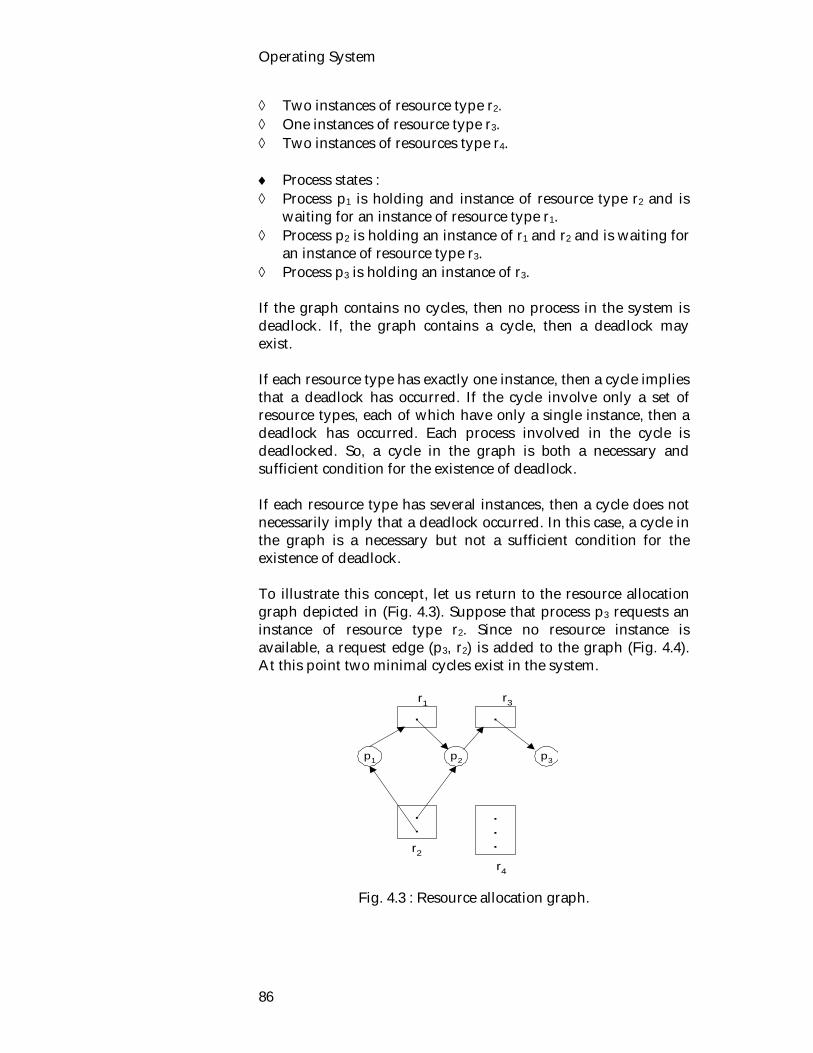
Operating System
86
Two instances of resource type r2. One instances of resource type r3. Two instances of resources type r4. Process states : Process p1 is holding and instance of resource type r2 and is
waiting for an instance of resource type r1. Process p2 is holding an instance of r1 and r2 and is waiting for
an instance of resource type r3. Process p3 is holding an instance of r3. If the graph contains no cycles, then no process in the system is deadlock. If, the graph contains a cycle, then a deadlock may exist. If each resource type has exactly one instance, then a cycle implies that a deadlock has occurred. If the cycle involve only a set of resource types, each of which have only a single instance, then a deadlock has occurred. Each process involved in the cycle is deadlocked. So, a cycle in the graph is both a necessary and sufficient condition for the existence of deadlock. If each resource type has several instances, then a cycle does not necessarily imply that a deadlock occurred. In this case, a cycle in the graph is a necessary but not a sufficient condition for the existence of deadlock. To illustrate this concept, let us return to the resource allocation graph depicted in (Fig. 4.3). Suppose that process p3 requests an instance of resource type r2. Since no resource instance is available, a request edge (p3, r2) is added to the graph (Fig. 4.4). At this point two minimal cycles exist in the system.
Fig. 4.3 : Resource allocation graph.
..
.
....
p1 p2 p3
r1 r3
r2
r4
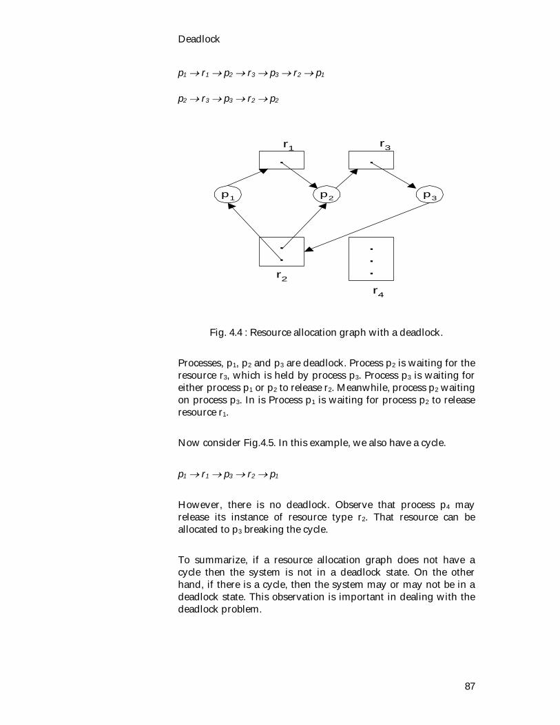
Deadlock
87
p1 r1 p2 r3 p3 r2 p1 p2 r3 p3 r2 p2
Fig. 4.4 : Resource allocation graph with a deadlock. Processes, p1, p2 and p3 are deadlock. Process p2 is waiting for the resource r3, which is held by process p3. Process p3 is waiting for either process p1 or p2 to release r2. Meanwhile, process p2 waiting on process p3. In is Process p1 is waiting for process p2 to release resource r1. Now consider Fig.4.5. In this example, we also have a cycle. p1 r1 p3 r2 p1 However, there is no deadlock. Observe that process p4 may release its instance of resource type r2. That resource can be allocated to p3 breaking the cycle. To summarize, if a resource allocation graph does not have a cycle then the system is not in a deadlock state. On the other hand, if there is a cycle, then the system may or may not be in a deadlock state. This observation is important in dealing with the deadlock problem.
..
.
....
p1 p2 p3
r1 r3
r2
r4
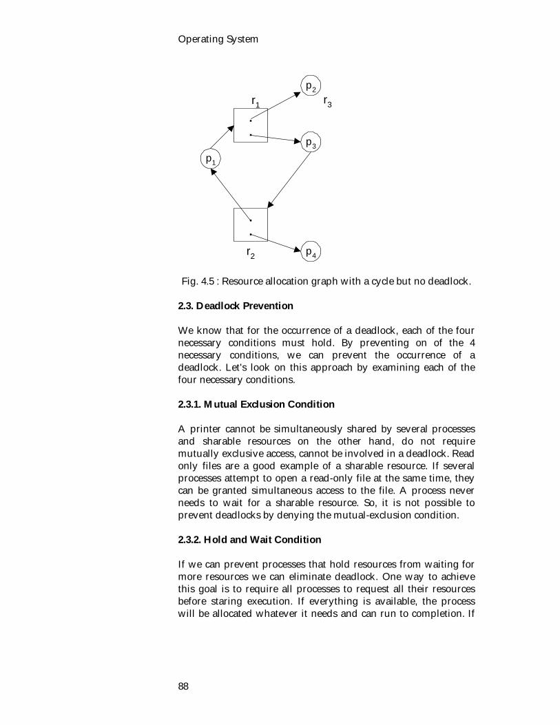
Operating System
88
Fig. 4.5 : Resource allocation graph with a cycle but no deadlock.
2.3. Deadlock Prevention We know that for the occurrence of a deadlock, each of the four necessary conditions must hold. By preventing on of the 4 necessary conditions, we can prevent the occurrence of a deadlock. Let's look on this approach by examining each of the four necessary conditions. 2.3.1. Mutual Exclusion Condition A printer cannot be simultaneously shared by several processes and sharable resources on the other hand, do not require mutually exclusive access, cannot be involved in a deadlock. Read only files are a good example of a sharable resource. If several processes attempt to open a read-only file at the same time, they can be granted simultaneous access to the file. A process never needs to wait for a sharable resource. So, it is not possible to prevent deadlocks by denying the mutual-exclusion condition. 2.3.2. Hold and Wait Condition If we can prevent processes that hold resources from waiting for more resources we can eliminate deadlock. One way to achieve this goal is to require all processes to request all their resources before staring execution. If everything is available, the process will be allocated whatever it needs and can run to completion. If
.
.
.
.
p1
p2
p3
r1 r3
r2 p4

Deadlock
89
one or more resources are busy, nothing will be allocated and the process would just wait. Another way to break the hold-and-wait condition is to require a process requesting a resource to first temporarily release all the resources it currently holds. Then it tries to get everything it needs all at once. There are two main disadvantages to these protocols. First resource utilization may be very low, since many of the resources may be allocated but unused for a long period of time. In the example given below, will make it clear. A process that reads data from an input tape, analyzes it for an hour and then writes an output tape as well as plotting the results. If all the resources must be requested in advance, the process will up the output tape drive tie and the plotter for an hour. Second, starvation is possible. A process that needs several popular resources may have to wait indefinitely while at least one of the resources that it needs is always allocated to some other process. advantage It is easy to code. 2.3.3. No Preemption Condition If we can severe that no preemption does not hold, we can eliminate deadlocks. The protocol is as follows : If a process that is holding some resources requests another resource that cannot be immediately allocated to it (that is the process must wait) then all resources currently being held are preempted. That is, these resources are implicitly released. The preempted resources are added to the list of resources for which the process is waiting. The process will only be restarted when it can regain its old resources, as well as the new ones that it is requesting. 2.3.4. Circular wait Conditions By preventing the circular wait from occurring, we can eliminate deadlock. For this, resources are uniquely numbered (Fig. 4.6(a))

Operating System
90
and processes can only request resources in linear ascending order. Now the protocol is this : processes can request resources whenever they want to, but all requests must be made in numerical order. A process may request a first card reader and then a tape drive, but it may not request first a printer and then disk drive. With this rule, the resource allocation graph can never have cycles. Let us see why this is true for the case of two processes, in Fig. 4.6(b). We can get a deadlock only if C request resource j and D requests resource i. Assuming i and j are distinct resources, they will have different numbers. If i j the C is not allowed to request j. If i j then C is not allowed to request i. Thus, dead look is impossible.
1. card reader 2. disk drive 3. tape drive 4. printer.
Fig. 4.6 : (a) Numerically ordered resources (b) A resource graph. 2.4. Exercise 2.4.1. Questions for short answers a) What do you understood by resource allocation graph? b) What is a request edge and assignment edge? 2.4.2. Analytical questions 1. Explain that a) a cycle in the graph is both a necessary and sufficient
condition for existence of deadlock. b) a cycle in the graph is a necessary but not a sufficient
condition for the existence of deadlock. 2. What do you know about deadlock prevention?
C D
i j
(a) (b)
Deadlock
91
Lesson 3 : Deadlock Avoidance 3.1. Learning Objectives On completion of this lesson you will be able to : explain deadlock avoidance define safe state and unsafe state know banker's algorithm. 3.2. Deadlock Avoidance Avoidance strategies are designed to allocate only when it is certain that deadlock can not occur as a result of the allocation. The basic observation behind avoidance strategies is that the set of all states can be partitioned into safe states and unsafe state(states that are not safe). 3.2.1. Safe State and Unsafe State A safe state is one in which it can be determined that the system can allocate resources to each process (up to its maximum) in some order (for all pending requests) and still avoid deadlock. A safe state is not a deadlock state. A deadlock state is an unsafe state. Not all unsafe states are deadlocks but an unsafe state may lead to a deadlock. As long as the state is safe, the operating system can avoid unsafe (deadlock) states. Process that are holding resources in an unsafe state may subsequently release them rather than ask for more; the system would transition from an unsafe state back into a safe state. The difference between a safe state and an unsafe state is that from a safe state the system can guarantee that all processes will finish, whereas from an unsafe state, no such guarantee can be given. It will be more clear to illustrate safe state and unsafe state by an example. Suppose a system has 12 disk drive and three processes : P0, P1 and P2. Process P0 require ten disk drives, process P1 may need four, and process P2 may need up to nine disk drives. At time T0 process P0 is holding five disk drives, process P1 is holding two, and process P2 is holding two. So, there are three free disk drives (Fig. 4.7(a)).
The difference between a safe state and an unsafe state is that from a safe state the system can guarantee that all processes will finish, whereas from an unsafe state, no such guarantee can be given.

Operating System
92
Process
Hold Max Process
Hold Max Process
Hold Max
P0 5 10 P0 5 10 P0 5 10 P1 2 4 P1 4 4 P1 0 - P2 2 9 P2 2 9 P2 9 2
Free : 3 Free :1 Free: 5 (a) (b (c)
Process
Hold Max Process
Hold Max Process
Hold Max
P0 10 10 P0 0 - P0 0 - P1 0 - P1 0 - P1 0 - P2 2 9 P2 2 9 P2 9 9
Free : 0 Free : 10 Free : 3 (d) (e) (f)
Process Hold Max P0 0 - P1 0 - P2 0 -
Free : 12 (g)
Fig. 4.7 : Demonstration that the state is safe. The system is in a safe state. The sequence <p1, p0, p2> satisfies the safety condition, since process p1 can immediately be allocated all of its disk drives (Fig. 4.7(b)) and return them and the system will then have five available disk drives (Fig. 4.7(c)). Process p0 can get all of its disk drives and return them, the system will then have ten available disk drives (Fig. 4.7(e)) and finally process p2 could get all of its disk drives and return them. The system will then have all twelve disk drives available (Fig. 4.7(g)). Let's look how to go from a safe state to an unsafe state. At time t1, process p2 requests and is allocated one more disk drive (Fig. 4.8(b)). The system is no longer in a safe state. At this point, only process p1, can be allocated all of its disk drives. When it returns them, the system have only four available disk drives (Fig. 4.8(d)). Since process p0 is allocated five tape drives, but has a maximum of ten, it may then request five more. Since they are unavailable, process p0 must wait. Similarly, process p2 may request an additional six tape drives and have to wait, resulting in a deadlock.
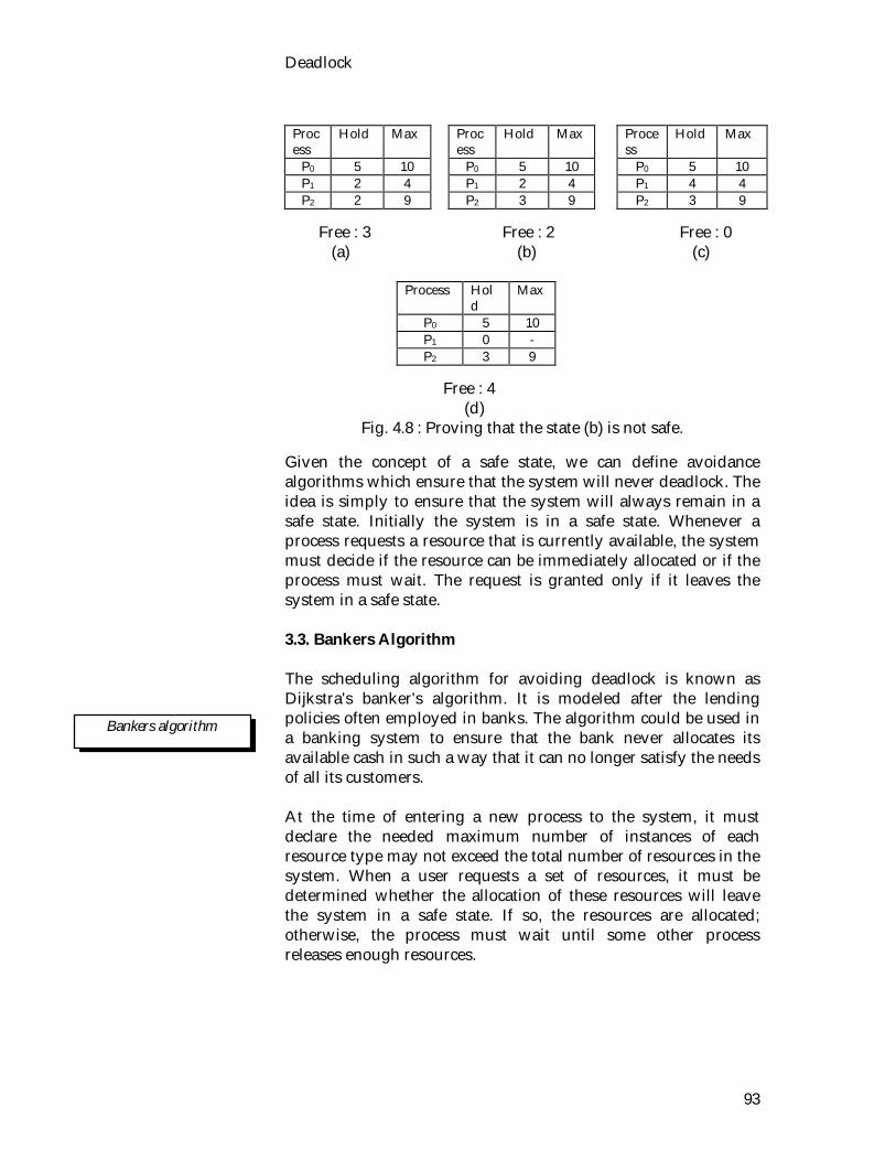
Deadlock
93
Process
Hold Max Process
Hold Max Process
Hold Max
P0 5 10 P0 5 10 P0 5 10 P1 2 4 P1 2 4 P1 4 4 P2 2 9 P2 3 9 P2 3 9
Free : 3 Free : 2 Free : 0 (a) (b) (c)
Process Hold
Max
P0 5 10 P1 0 - P2 3 9
Free : 4 (d)
Fig. 4.8 : Proving that the state (b) is not safe. Given the concept of a safe state, we can define avoidance algorithms which ensure that the system will never deadlock. The idea is simply to ensure that the system will always remain in a safe state. Initially the system is in a safe state. Whenever a process requests a resource that is currently available, the system must decide if the resource can be immediately allocated or if the process must wait. The request is granted only if it leaves the system in a safe state. 3.3. Bankers Algorithm The scheduling algorithm for avoiding deadlock is known as Dijkstra's banker's algorithm. It is modeled after the lending policies often employed in banks. The algorithm could be used in a banking system to ensure that the bank never allocates its available cash in such a way that it can no longer satisfy the needs of all its customers. At the time of entering a new process to the system, it must declare the needed maximum number of instances of each resource type may not exceed the total number of resources in the system. When a user requests a set of resources, it must be determined whether the allocation of these resources will leave the system in a safe state. If so, the resources are allocated; otherwise, the process must wait until some other process releases enough resources.
Bankers algorithm

Operating System
94
The following data structures must be maintained to implement the banker's algorithm. 3.3.1. Data Structures Available : A vector of length l indicating the number of available resources of each type. If Available [j] = k, there are k instances of resources type rj available. Max : An l x m matrix defining he maximum demand of each process. If Max (i,j) = k, then process pj may request at most k instances of resource type rj, where m is the No. of process, l is the No. of resource types. Allocation : An l x m matrix defining the number of resources of each type currently allocated to each process. If Allocation [i,j] = k, then process pi is currently allocated k instances of resource type rj. Need : An l x m matrix indicating the remaining resource need of each process. If Need (i,j) = k, then process pi may need k more instances of resource type rj, in order to complete its task. Note that Need(i,j) = Max(i,j) - Allocation(i,j). 3.3.2. Algorithm Let, Requesti be the request vector for process pi. If Requesti[j] = k, then process pi wants k instances of resource type rj. When a request for resources is made by process pi the following actions are taken:
1. If Requestr Needi then go to step 2. Otherwise error. 2. If Requesti Available then go to step 3. Otherwise the
resources are not available, and pi must wait. 3. Modify the state as follows.
Available : = Available - Requesti Allocationi : Allocationi + Requesti Needi = Needi - Requesti
If the state is safe, the transaction is completed and process pi is allocated its resources. However, if the new state is unsafe, then pi must wait for Requesti and the old resource allocation state is restored. The algorithm for finding out whether a system is in a safe state or not can be described as follows : 3.3.3. Safety Algorithm
Deadlock
95
1. Let work and Finish be vectors of length m and n, respectively. Initialize Work : = Available and Finish [i] : = false for i = 1, 2, ..., n.
2. Find an i such that :
a. Finish[i] = false, and b. Needi Work.
If no such i exists, go to step 4. 3. Work : = Work + Allocation, Finish[i] : = true go to step 2. 4. If Finish[i] = true for all i, then the system is in a safe state. Example, Consider a system with five processes {po, p1 ..., p4} and three resource types. Resource type r1 has 10 instances, resource type r2 has 5 instances, and resource type r3 has 7 instances. Suppose that at time T0 the following snapshot of the system has been taken.
Allocation Max Available r1 r2 r3 r1 r2 r3 r1 r2 r3 p0 p1 p2 p3 p4
0 1 0 2 0 0 3 0 2 2 1 1 0 0 2
7 5 3 3 2 2 9 0 2 2 2 2 4 3 3
3 3 2
The content of the matrix Need is defined to be Max - Allocation and is :
Need r1 r2 r3 p0 p1 p2 p3 p4
7 4 3 1 2 2 6 0 0 0 1 1 4 3 1
The system is currently in a safe state and the sequence <p1, p3, p4, p2, p0> satisfies the safety criteria.

Operating System
96
Now the process p1 requests one additional instance of resource type r1 and two instances of resources of resource type r2, so Request1 = (1, 0, 2). In order to decide whether this request can be immediately granted, we first check that Request1 Available (1, 0, 1) (3, 2, 2) which is true. So, this request has been fulfilled and arrive at the following new state :
Allocation Need Available r1 r2 r3 r1 r2 r3 r1 r2 r3
p0 p1 p2 p3 p4
0 1 0 3 0 2 3 0 2 2 1 1 0 0 2
7 5 3 0 2 0 6 0 0 0 1 1 4 3 1
2 3 0
For checking whether this new system state is safe, we have to execute our safety algorithm and find out that the sequence <p1, p3, p4, p0, p2> satisfies our safety requirement. So a request for (3, 3, 0) by p4 cannot be granted since the resources are not available. A request for (0, 2, 0) by p0 cannot be granted even though the resources are available, since the resulting state is unsafe. 3.4. Exercise 3.4.1. Questions for short answers a) What do you understand by safe state? b) What do you understand by unsafe state? c) Describe safety algorithm. 3.4.2. Analytical questions a) What do you understand by safe state and unsafe state?
Illustrate with example. b) Given a system that uses the banker's algorithm for
avoiding deadlock and the resource state shown below.
Allocation Max Available p0 p1 p2 p3 p4
0 0 1 2 1 0 0 0 1 3 5 4 0 6 3 2 0 0 1 4
0 0 1 2 17 5 0 23 5 6 0 6 5 2 0 6 5 6
1 5 2 0
Answer the following questions using the banker's algorithm : a) What is the content of the array Need?
Deadlock
97
b) Is the system in a safe state? c) If a request from process p1 arrives for (0, 4, 2, 0),
immediately granted? Lesson 4 : Deadlock Recovery 4.1. Learning Objectives On completion of this lesson, you will be able to know:
how to recover from deadlock the combined approach of handling deadlock. 4.2. Deadlock Recovery Detection is only one part of he solution of deadlock problem. After detecting deadlock with the help of detection algorithm, what should be done next. There should be some way in the system needed to recover from deadlock and get the system going again. There are two ways for breaking a deadlock :
Recovery through killing process. Recover through resource preemption.
4.2.1. Recovery Through Killing Process For eliminating the deadlock by killing a process the following two methods can be used:
Kill all Deadlock Processes Kill one process at a time until the deadlock cycle is
eliminated. Kill all Deadlock Processes By killing all deadlocked processes will break the deadlock cycle. These processes many have computed for long time and result of these partial computation must be discarded and can be re-computed later. Kill one process at a time until the deadlock cycle is eliminated After each process is killed, the other processes will be able to continue and a deadlock detection algorithm must be involved to determine whether any processes are still deadlocked.

Operating System
98
For partial computation, we have to determine which process should be terminated to try to break the deadlock. Many factors are related to determine which process is chosen.
Priority of the process. Computing time. Number and type of resources used by process. Number of extra resources for completion. Number of process involved in the deadlock.
It is best to kill a process that can be rerun. From the beginning with no ill effects. As for example, a compilation can always be rerun because all it does is read a source file and produce an object file. If it is killed part way through, the first run has no inference on the second run. 4.2.2. Recovery Through Preemption For eliminating deadlock using resource preemption, we can preempt resources from processes and give these resources to other processes until the deadlock cycle is broken. The following issues are related to preemption : Selection of a Victim and Rollback Selection of a Victim We have to determine the resources and processes to be preempted and determine the order of preemption cost. Consider deadlock situation involving two people A and B. Case 1: A has a higher priority than B. So, B will have to back up. Case 2: A needs only 2 more stepping stones to cross the river (i.e. A has already used 98 stepping stones). So, B have to back up. Case 3: A and B deadlock in the middle of the river. There are ten people behind A. So it would be more reasonable to require B have to back up. Otherwise, eleven people will have to back up. Rollback The solution of a rollback is to abort the process and then restart it. Let us go through river crossing example. If we preempt a

Deadlock
99
resource from a process, it cannot continue with its normal execution; it is missing some needed resource. So, We have to roll the process back to some safe state and restart it from that state. An effective solution of rollback is to place several additional stepping stones in the river, so that one of the people involved in the deadlock may step aside to break the deadlock. 4.3. Combined Approach It has been argued that none of the presented approaches is suitable for use as an exclusive method of handling deadlocks in a complex system. The presented approaches i.e. deadlock prevention, avoidance and detection can be combined for maximum effectiveness. The proposed method is based on the notion that resources can be partitioned into classes that are hierarchically ordered. A resource ordering technique can be applied to the classes. Within each class the most appropriate technique for handling deadlock is used. Consider a system that consists of the four classes of resources described below.
Swapping space, an area of secondary storage designated for backing up blocks of main memory.
Job resources and assignable devices; such as printers and drives with removable media (e.g., tapes, cartridge disks, floppies)
Main memory assignable on a block basis, such as pages or segments.
Internal resources, such as I/O channels and slots of the pool of dynamic memory.
The basic idea is to provide deadlock prevention between the four classes of resources by linear ordering of requests in the presented order. The following strategies may be applied to individual resource classes. Swapping Space : Prevention of deadlocks by means of advanced acquisition of all needed space is a possibility for the swapping space. Deadlock avoidance is also possible, but deadlock detection is not, since there is no backup of the swapping store.
Classes of resources
Operating System
100
Job Resources : Avoidance of deadlock is facilitated by the proclaiming of resource requirements which is customarily done for jobs by means of the job-control statements. Deadlock prevention through resource ordering is also a probability, but detection and recovery are undesirable due to the possibility of modification of files that belong to this class of resources. Main Memory : With swapping, prevention through preemption is a reasonable choice. That allows support for run-time growth (and shrinking) of memory allocated to resident processes. Avoidance is undesirable because of its run-time overhead and tendency to underutilized resources. Deadlock detection is possible but undesirable due to either the return-time overhead for frequent detection or the unused memory held by deadlocked processes. Internal System Resources : Due to frequent requests and releases of resources and the resulting frequent changes of state, the run-time overhead of deadlock avoidance and detection can hardly be tolerated. Prevention through resource ordering is probably the best choice. 4.4. Exercises 4.4.1. Multiple choice questions
1. How many ways for breaking a deadlock?
i) 2 ii) 3 iii) 4 iv) None of the above.
2. Killing all deadlocked processes
i) Will not break the deadlock cycle. ii) Will break the deadlock cycle . iii) Cause the deadlock problem. iv) None of the above. 4.4.2. Questions for short answers a) List the factors for choosing the process. b) What do you understood by rollback? What is the effective
solution to rollback? 4.4.3. Analytical questions
Strategies of resources classes.

Deadlock
101
a) Describe the different methods of deadlock recovery. b) Why combined approach for handling deadlock is used?
Describe combined approach.
Unit 5 : Primary Memory Management
Memory management is primary concerned with allocation of physical memory of finite capacity to requesting processes. No process may be activated before a certain amount can be allocated to it. The overall resource utilization and other performance criteria of a computer system are affected by performance of the memory management module not only in terns of its effectiveness in allocating memory, but also as a consequence of its influence on and interaction with, scheduler in this unit we discuss various aspect memory management ranging from relocation to segmentation. In the last lesson we concentrate on virtual memory and page replacement algorithm. Lesson 1 : Relocation, Protection and
Sharing 1.1. Learning Objectives On completion of this lesson you will be able to know : the relocation scheme the different types of relocation scheme sharing and protection. 1.2. Introduction Memory management mechanism performs the address translation from logical to physical. Before going through swapping, paging and other memory management techniques, we have to know some terms such as:
Relocation Protection Sharing.
1.2.1. Relocation Relocation is the process of moving a process, code and data around in main memory without having to recompile. In other words, relocation refers to the ability to load and execute a given

Operating System
102
program into an arbitrary in memory, as opposed to fixed set to locations specified at program translation time. Two forms exists: static and dynamic. Static Relocation Static relocation implies that the relocation is performed before or during the loading of the program into memory, by a relocating linker or a relocating loader. Dynamic Relocation Dynamic relocation implies that mapping from the logical address space to the physical address space is performed at run-time, usually with some hardware assistance. Process images in systems with dynamic relocation are also prepared assuming the starting location to be a virtual address 0, and they are loaded in memory without any relocation adjustments. When the related process is being executed, all of its memory references are relocated during instruction execution before the physical memory is actually accessed. This process is often implemented by means of specialized base registers. Dynamic relocation is illustrated in Fig.5.1.
cpu
12000
+
memory
MOVE A, 0468
MOVE A, 0468
Processimage
logicaladdress
physicaladdress
baseregister
0468 12468
Fig. 5.1 : Dynamic relocation using a relocation register. The value in the base register is added to every address generated by a user process at the time it is sent to memory. For example, if the fence is at 12000, then an attempt by the user to address location 0 is dynamically relocated to location 12000, an access to location 0468 is relocated to location 12468.
A statically relocated program cannot be moved.
Relocation done at linking or at loading.
Primary Memory Management
103
Relocation of memory references at run-time can be illustrated by means of the instruction MOVE A, 0468, which is supposed to load the contents of the logical address 0468 (relative to program beginning) into the accumulator. As indicated, the target item actually reside at the physical address 12468 in memory. Dynamic relocation makes it possible to move a partially executed process from one area of memory into another without affecting its ability to access instructions and data correctly in the new space. This feature is very useful for support of swapping without binding of processes to partitions, and for dynamic partitioning. Using dynamic relocation a code section can be moved at any time. 1.2.2. Relative, Logical and Physical Addresses Logical Address The logical address is the address that the software/program uses. Relocation is obtained by allowing programs to use logical addresses that never change. The operating system and hardware performs the necessary translation form the logical address into the actual physical address. The majority of the translation must be performed by hardware because it is faster. This allows the operating system to move programs around in memory without the addresses used by the program to change. Only the OS needs to know it has change. Relative Address A form of logical address. A relative address is actually a displacement from the start of the programs memory section. The physical address is obtained by adding the relative address to the physical address at which the program starts. For example, Load A, 100 If 100 is a relative address and this program starts at the physical address 5467 then the actual physical address used in the above instruction is 5467 + 100 = 5567.
The logical address is the address that the software/program uses.
A relative address is actually a displacement from the start of the programs memory section.

Operating System
104
If the operating system moves the process in memory then the physical address is new base address + 100 Bounds Registers
Bounds registers are special CPU registers used in some relocation schemes. Relocation is handled by the upper and lower bounds registers containing the actual physical upper and lower addresses used by the process. The address references (logical addresses) used by the process are relative addresses. The translation from logical to physical address is achieved by adding the logical address to the lower bounds register. If the physical address that results is higher than the upper bound then an error is generated. For a process to be relocated the operating system changes the values in the upper and lower bounds registers are changed and the process code is copied into the appropriate memory location. 1.2.2. Protection We need to protect the monitor code and data from changes by the user program. This protection must be provided by the hardware and can be implemented in several ways. Memory management strategies must implement protection of some form. Processes should only access memory they are allowed to. 1.2.3. Sharing A good Memory management mechanism must also provide for controlled sharing of data and code between cooperation process. Processes which are executing the same program should be able to share code. Processes may also wish to share data. Examples of sharing include :
multiple processes sharing the same program code shared or dynamic link libraries.

Primary Memory Management
105
1.3. Exercise 1.3.1. Multiple choice questions 1. Dynamic relocation is one in which i) Relocation is done at linking ii) Relocation is done at loading iii) Relocation is done using relocation register at run-time iv) None of the above. 1.3.2. Questions for short answers a) What is relocation? b) How is dynamic relocation achieved using bounds
registers? c) What do you mean by protection and sharing? d) Consider the instruction load B, 468, starting physical
address 1000, what will be the new physical address? 1.3.3. Analytical questions a) How do relative, logical and physical addresses relate to
relocation? b) Describe different types of relocation?
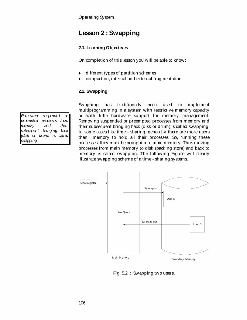
Operating System
106
Lesson 2 : Swapping 2.1. Learning Objectives On completion of this lesson you will be able to know: different types of partition schemes compaction, internal and external fragmentation. 2.2. Swapping Swapping has traditionally been used to implement multiprogramming in a system with restrictive memory capacity or with little hardware support for memory management. Removing suspended or preempted processes from memory and their subsequent bringing back (disk or drum) is called swapping. In some cases like time - sharing, generally there are more users than memory to hold all their processes. So, running these processes, they must be brought into main memory. Thus moving processes from main memory to disk (backing store) and back to memory is called swapping. The following Figure will clearly illustrate swapping scheme of a time - sharing systems.
User Space
User A
User B
fence register
(1) swap out
(2) swap out
Main Memory Secondary Memory
Fig. 5.2 : Swapping two users.
Removing suspended or preempted processes from memory and their subsequent bringing back (disk or drum) is called swapping.
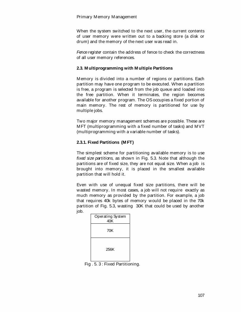
Primary Memory Management
107
When the system switched to the next user, the current contents of user memory were written out to a backing store (a disk or drum) and the memory of the next user was read in. Fence register contain the address of fence to check the correctness of all user memory references. 2.3. Multiprogramming with Multiple Partitions Memory is divided into a number of regions or partitions. Each partition may have one program to be executed. When a partition is free, a program is selected from the job queue and loaded into the free partition. When it terminates, the region becomes available for another program. The OS occupies a fixed portion of main memory. The rest of memory is partitioned for use by multiple jobs. Two major memory management schemes are possible. These are MFT (multiprogramming with a fixed number of tasks) and MVT (multiprogramming with a variable number of tasks). 2.3.1. Fixed Partitions (MFT) The simplest scheme for partitioning available memory is to use fixed size partitions, as shown in Fig. 5.3. Note that although the partitions are of fixed size, they are not equal size. When a job is brought into memory, it is placed in the smallest available partition that will hold it. Even with use of unequal fixed size partitions, there will be wasted memory. In most cases, a job will not require exactly as much memory as provided by the partition. For example, a job that requires 40k bytes of memory would be placed in the 70k partition of Fig. 5.3, wasting 30K that could be used by another job.
Operating System 40K
70K
256K
Fig . 5. 3 : Fixed Partitioning.

Operating System
108
Problems
Number of partitions limits number of active jobs. Suffer from internal fragmentation. Small jobs do not use partition space efficiently. Use of fixed partitioning is almost unknown today. Used in early IBM mainframe OS.
Advantage
Fixed partition primary memory can eliminate the need for dynamic relocation problem.
Swapping can be used in conjunction with fixed partition mechanism.
Internal fragmentation A job which needs p words of memory may be run in a region or partition e.g. words, where q≥p. The difference between these two numbers (q-p) is internal fragmentation, memory which is internal to a region. 2.3.2. Variable Partitions (MVT) A swapping system could be based on fixed partitions. Whenever a job is blocked, it could be moved to the disk and another job brought into its partition from disk. Actually, fixed partitions are unattractive when memory is scarce because too much of it is wasted by programs that are smaller than their partitions. The another problem with MFT is determining the best partition sizes to minimize internal and external fragmentation. The solution to this problem is to allow the region sized to vary dynamically. This approach is called multiple contiguous variable partition allocation. Implementation The operating system keeps a table of memory hole. Memory hole is the sections of RAM not currently being used. The Memory hole can be contiguous or noncontiguous. When a job enters the system it is allocated exactly the amount of memory it needs from memory hole. When finishes it returns its used memory to memory hole.

Primary Memory Management
109
Operating
System
216K
Fig. 5.4 : MVT scheduling example. Example Assume that we have 256K memory available and a operating system of 40K. This situation leaves 216K for user programs, as shown in Fig. 5.4. Initially the first three jobs are loaded in , starting where the OS ends (Fig.5.5(a)). This leaves a 'hole' at the end of memory that is too small (e.g. 36K of memory) for the 4th job. This is called external fragmentation. When job2 terminates or is swapped out, there is room for job4 (Fig. 5.5(b)). Since job4 is smaller than job2, so after scheduling job4 another small hole is created (Fig.5.5(c)). When job1 is swapped out ; there is room for job5 (Fig. 5.5(d)) After scheduling job5, (Fig. 5.5(e)) will result. From the illustrated example, it is found that there are a set of holes, of various sizes, scattered through the memory. As time goes on , memory becomes more & more fragmented and memory utilization declines. So, MVT has external fragmentation.
Job Queue Job Memory Time 1 50K 10 2 90K 5 3 40K 20 4 70K 8 5 45K 15
0
40K
256K
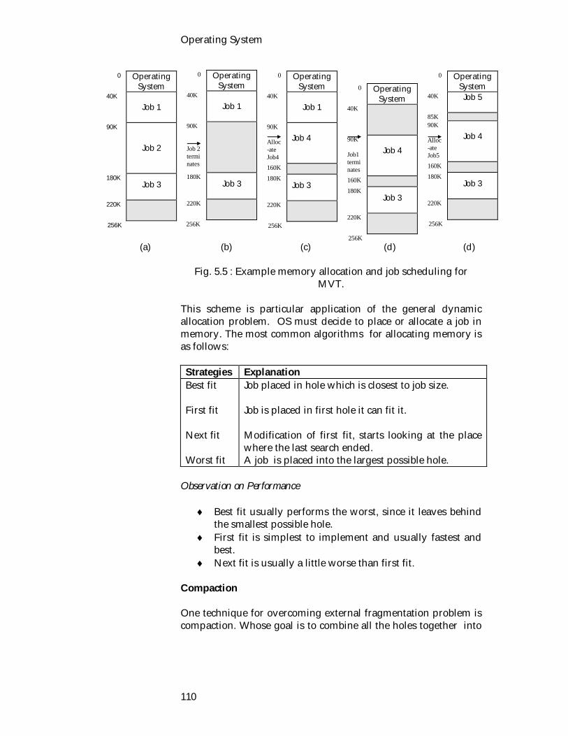
Operating System
110
(a) (b) (c) (d) (d)
Fig. 5.5 : Example memory allocation and job scheduling for MVT.
This scheme is particular application of the general dynamic allocation problem. OS must decide to place or allocate a job in memory. The most common algorithms for allocating memory is as follows: Strategies Explanation Best fit First fit Next fit Worst fit
Job placed in hole which is closest to job size. Job is placed in first hole it can fit it. Modification of first fit, starts looking at the place where the last search ended. A job is placed into the largest possible hole.
Observation on Performance
Best fit usually performs the worst, since it leaves behind the smallest possible hole.
First fit is simplest to implement and usually fastest and best.
Next fit is usually a little worse than first fit. Compaction One technique for overcoming external fragmentation problem is compaction. Whose goal is to combine all the holes together into
0 Operating System
40K Job 1
90K Job 2 terminates
180K
Job 3
220K
256K
0 Operating System
40K Job 1
90K Alloc-ate Job4
Job 4
160K 180K
Job 3
220K
256K
0 Operating System
40K Job 1
90K
Job 2
180K
Job 3
220K
256K
0 Operating System
40K
90K Job1 terminates
Job 4
160K 180K
Job 3
220K
256K
0 Operating System
40K
Job 5
85K
90K Alloc-ate Job5
Job 4
160K 180K
Job 3
220K
256K
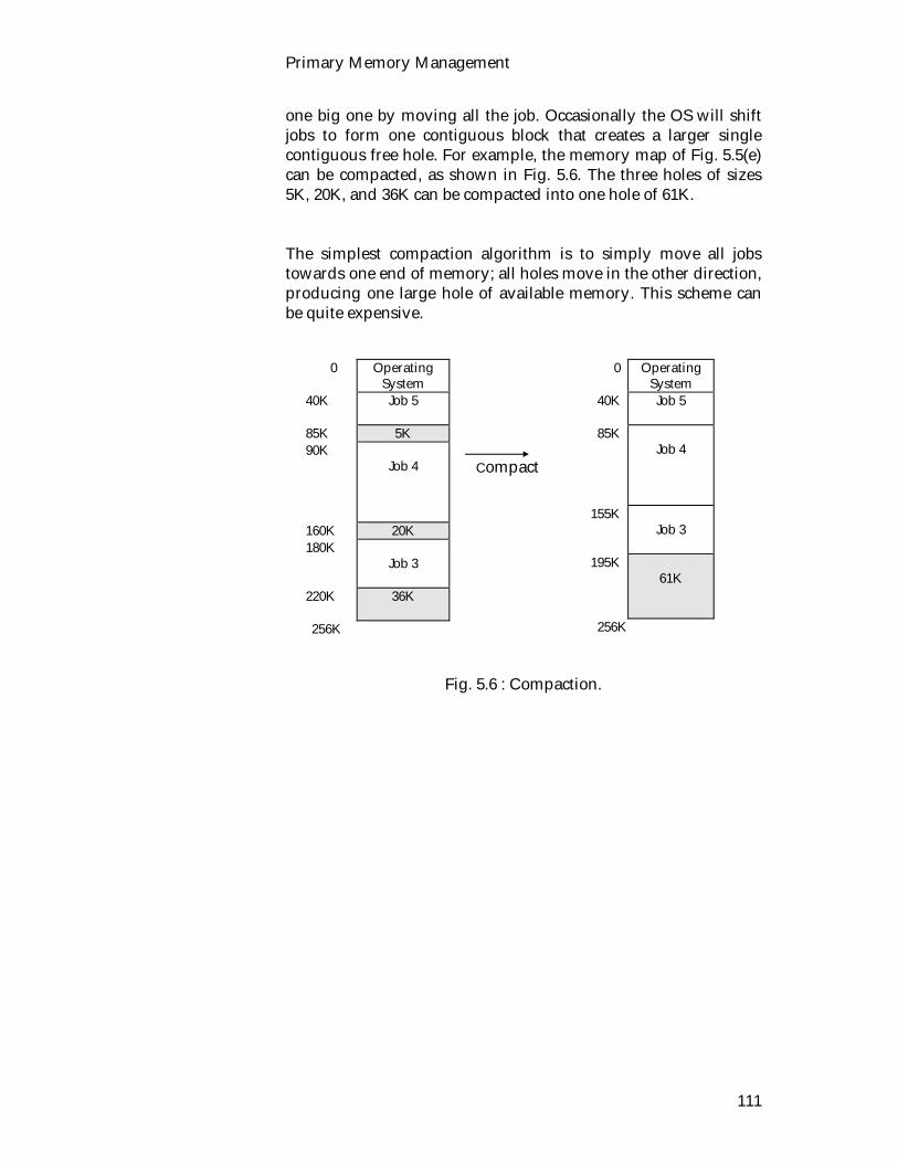
Primary Memory Management
111
one big one by moving all the job. Occasionally the OS will shift jobs to form one contiguous block that creates a larger single contiguous free hole. For example, the memory map of Fig. 5.5(e) can be compacted, as shown in Fig. 5.6. The three holes of sizes 5K, 20K, and 36K can be compacted into one hole of 61K. The simplest compaction algorithm is to simply move all jobs towards one end of memory; all holes move in the other direction, producing one large hole of available memory. This scheme can be quite expensive. Compact
Fig. 5.6 : Compaction.
0 Operating System
40K
Job 5
85K 5K 90K
Job 4
160K 20K 180K
Job 3
220K 36K
256K
0 Operating System
40K Job 5
85K
Job 4
155K Job 3
195K
61K
256K

Operating System
112
2.4. Exercise 2.4.1. Multiple choice questions 1. Which of the following is true for internal fragmentation? i) memory which is internal to a region ii) memory which is external to a region iii) memory which is swapped out iv) none of the above. 2. First fit is i) the fastest and best ii) the worst iii) is little worse than next fit iv) all of the above. 2.4.2. Questions for short answers a) Explain the following allocation algorithms
i) First fit ii) best fit iii) worst fit
b) What do you understand by swapping? c) What are the problems in fixed partitions? How can you
solve this? d) What do you mean by internal fragmentation? e) How can solve external fragmentation problem? f) Explain how to implement variable partition. 2.4.3. Analytical question a) Describe variable partition allocation with an example.
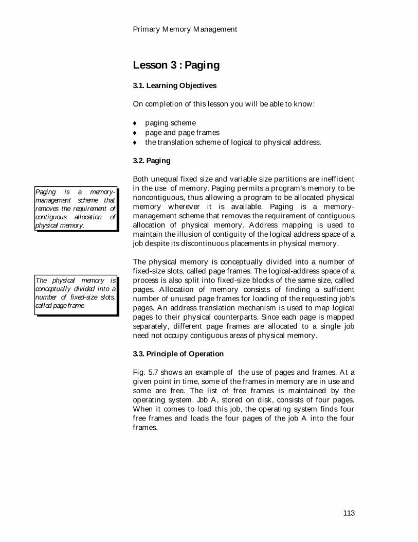
Primary Memory Management
113
Lesson 3 : Paging 3.1. Learning Objectives On completion of this lesson you will be able to know: paging scheme page and page frames the translation scheme of logical to physical address. 3.2. Paging Both unequal fixed size and variable size partitions are inefficient in the use of memory. Paging permits a program's memory to be noncontiguous, thus allowing a program to be allocated physical memory wherever it is available. Paging is a memory-management scheme that removes the requirement of contiguous allocation of physical memory. Address mapping is used to maintain the illusion of contiguity of the logical address space of a job despite its discontinuous placements in physical memory. The physical memory is conceptually divided into a number of fixed-size slots, called page frames. The logical-address space of a process is also split into fixed-size blocks of the same size, called pages. Allocation of memory consists of finding a sufficient number of unused page frames for loading of the requesting job's pages. An address translation mechanism is used to map logical pages to their physical counterparts. Since each page is mapped separately, different page frames are allocated to a single job need not occupy contiguous areas of physical memory. 3.3. Principle of Operation Fig. 5.7 shows an example of the use of pages and frames. At a given point in time, some of the frames in memory are in use and some are free. The list of free frames is maintained by the operating system. Job A, stored on disk, consists of four pages. When it comes to load this job, the operating system finds four free frames and loads the four pages of the job A into the four frames.
Paging is a memory-management scheme that removes the requirement of contiguous allocation of physical memory.
The physical memory is conceptually divided into a number of fixed-size slots, called page frame.
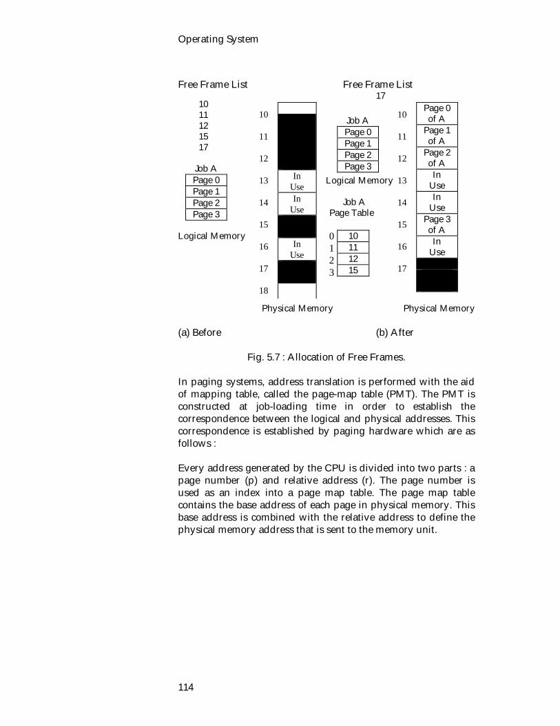
Operating System
114
Free Frame List Free Frame List 17 Logical Memory Job A Page Table Logical Memory Physical Memory Physical Memory (a) Before (b) After
Fig. 5.7 : Allocation of Free Frames. In paging systems, address translation is performed with the aid of mapping table, called the page-map table (PMT). The PMT is constructed at job-loading time in order to establish the correspondence between the logical and physical addresses. This correspondence is established by paging hardware which are as follows : Every address generated by the CPU is divided into two parts : a page number (p) and relative address (r). The page number is used as an index into a page map table. The page map table contains the base address of each page in physical memory. This base address is combined with the relative address to define the physical memory address that is sent to the memory unit.
Job A Page 0 Page 1 Page 2 Page 3
In Use In
Use
In Use
10 11 12 13 14 15 16 17 18
10 11 12 13 14 15 16 17
Job A Page 0 Page 1 Page 2 Page 3
10 11 12 15
Page 0 of A
Page 1 of A
Page 2 of A
In Use In
Use Page 3 of A
In Use
10 11 12 15 17
0 1 2 3
Primary Memory Management
115
Fig. 5.8 : General hardware support for paging. The operating system maintains a page table for each job. The page table shows the frame location for each page of the job. Within the program, each logical address consists of a page number and a relative address within the page. Recall that in the case of simple partitioning, a logical address is the location of a word relative to the beginning of the program; the CPU translates that into a physical address. With paging, the logical to physical address translation is still done by CPU hardware. Now, the CPU must know how to access the page table of the current process. Presented with a logical address (page number, relative address), the CPU uses the page table to produce a physical address (frame number, relative address). An example is shown in Fig. 5.9. This approach solves the problems raised earlier. Main memory is divided into many small equal-size frames. Each job is divided into frame-size pages: smaller job require fewer pages, larger jobs require more. When a job is brought in its pages are loaded into available frames, and a page table is set up.
physicalmemorycpu p r p r
f
logicaladdress
physicaladdress
page table
p

Operating System
116
Fig. 5.9 : Address Translation. 3.4. Exercise 3.4.1. Multiple choice questions 1. In the paging the physical memory is conceptually
divided into a number of i) Fixed size slots ii) vriable size slots iii) equal size slots iv) none of the above. 2. PMT stands for i) process map table ii) page map table iii) process message table iv) none of the above. 3.4.2. Questions for short answers a) What do you understand by paging, page frame and
pages? b) List the advantage of paging scheme. c) Draw paging hardware. 3.4.3. Analytical question a) Describe the mechanism of paging system.
Logical Address
2 30
Physical Address 2 30
Job A
Page Table 10
11 12 15
Page 0 of A
Page 1 of A
Page 2 of A
Page 3 of A
10 11 12 13 14 15

Primary Memory Management
117
Lesson 4 : Segmentation 4.1. Learning Objectives On completion of this lesson you will be able to : define segment and segmentation list the advantages of segmentation list the disadvantages of segmentation describe segmentation mechanism. 4.2. Segmentation Segmentation is the process of dividing up a program that is to be run into a number of segments of different sizes and placing these chunks in logical memory wherever they fit. What is a segment? A segment is a grouping of information that is treated as an entity. This may be one or many programs, a subroutine, function, symbol table. Paging is invisible to the programmer and serves the purpose of providing the programmer with a larger address space. On the other hand, segmentation is usually visible to the programmer and is provided as a convenience for organizing programs and data, and as a means for associating privilege and protection attributes with instruction and data. Segmentation allows the programmer to view memory as consisting of multiple address spaces or segments. Segments are of variable, indeed dynamic, size. Typically, the programmer or the operating system will assign programs and data to different segments. There may be a number of program segments for various types of programs as well as a number of data segments. Each segment may be assigned access and usage rights. Memory references consist of a (segment number, relative address) form of address. Segmentation is a memory management scheme which supports the user's view of memory Fig. 5.10. A logical address space is a collection of segments. Each segment has a length. Addresses specify both the segment name and the relative address within the segment. The user therefore specifies each address by two quantities : a segment name and relative address. Segments are
A way in which addressable memory can be subdivided, known as segmentation.

Operating System
118
numbered and referred to by a segment number rather than a segment name.
Program
Fig. 5.10 : User's view of a program. 4.2.1. Segmentation hardware address translation mechanism Fig. 5.11 represents a generic implementation of the address translation facility. The operating system maintains a segment table for each process (the segment table is ordinarily a segment itself). The segment table can be implemented in the primary memory )as a segment that will not be removed from the primary memory). The table is a set of entries, each called a segment descriptor, with fields representing the base, limit, for the segment. The base field is analogous to the contents of a segment relocation register, the limit field is the length of the segment. A logical address consists of two parts : a segment number (s), and relative address(r). The segment number is used as an index into the segment table. Each entry of the segment table has a segment base and a segment limit. The relative address r must be between 0 and the segment limit. If it is not, trap to the operating system. If this relative address is legal, it is added to the segment base to produce the address in physical memory of the desired word. The segment table is thus essentially an array of base/limit register pairs. The areas of logical memory into which the segments of a program are placed are not necessarily adjacent, so the operating system must keep track of where segments are stored by
Symbol
Table stack
COS SQR
Main Program

Primary Memory Management
119
constructing a segment table. Segment table helps the mapping of two dimensional address into a one dimensional.
Fig. 5.11 : Segmentation hardware. 4.2.2. Example Let us see example Fig. 5.12. We have five segments numbered from 0 through 4. The segments are actually stored in physical memory as shown. The segment table has a separate entry for each segment, giving the beginning address of the segment in physical memory (the base) and the length of that segment (the limit). For example, segment 1 is 300 words long, beginning at location 2200. Thus a reference to word 150 of segment 1 is mapped onto location 2000 + 150 = 2350. A reference to segment 4, word 852 is mapped to 2700 (the base of segment 4) + 750 = 3450. A reference to word 1420 of segment 3 would result in a trap to the operating system, since this segment is only 1200 words long. Disadvantage
Since the words of each segment must be contiguous, fragmentation can be a major problem, especially if segments are allowed to dynamically grow.
The size of the total address space is limited by the size of physical memory.
Disadvantage
CPU
limit base
Segment Table
memory< +
(s,r)
yes
no
trap; addressing error
s
Example

Operating System
120
Fig. 5.12 : Example segmentation. Advantage Segmentation has a number of advantages to the programmer over a non segmented address space:
It simplifies the handling of growing data structures. If the programmer does not know ahead of time how large a particular data structure will become, it is not necessary to guess. The data structure can be assigned its own segment, and the operating system will expand or shrink the segment as needed.
It allows programs to be altered and recompiled independently, without requiring that an entire set of programs be re-linked and reloaded. Again, this is accomplished using multiple segments.
It lends itself to sharing among job. A programmer can place a utility program or a useful table of data in a segment that can be addressed by other jobs.
Its lends itself to protection. Sense a segment can be constructed to contain a well-defined set of programs or data, the programmer or a system administrator can assign access privileges in a convenient fashion.
These advantages are not available with paging, which is invisible to the programmer. On the other hand, we have seen the paging
Symbol
Table Segment0
Stack Segment2
COS Segment1
SQR Segment3
Main Program Segment4
Limit Base 0 1200 5000 1 300 2200 2 700 1300 3 1200 3800 4 1100 2700
Advantage
0
Segment 2
1300
2000 Segment 1 2200 2500 Segment 4
2700
Segment 3
3800
Segment 0
5000 6200
Primary Memory Management
121
provides for an efficient form of memory management. To combine the advantages of both, some systems are equipped with the hardware and operating-system software to provide both. 4.2.3. Combined Approach In an effort to combat the inefficiency inherent in both of these processes, a combination of segmentation and paging is frequently used to minimize the amount of wasted space in memory or to improve on each. In this combined process, a program is first broken into segments and then the segments are broken into pages. Both segment and page tables are needed to keep track of the various program pieces, which increases the complexity with which the operating system must deal. The IBM 360/67 was an early segmented paging system. 4.3. Exercise 4.3.1. Multiple choice questions 1. Which of the following is not an example of a virtual
memory management scheme? i) Paging ii) Segmentation iii) Dynamic partitioning iv) Combine paging/segmentation. 2. Segmentation is i) invisible to the programmer ii) usually visible to the programmer iii) both visible and invisible to programmer iv) none of the above. 3. The words of each segment must be i) contiguous ii) non-contiguous iii) unlimited iv) all of the above.
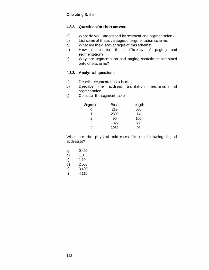
Operating System
122
4.3.2. Questions for short answers a) What do you understand by segment and segmentation? b) List some of the advantages of segmentation scheme. c) What are the disadvantages of this scheme? d) How to combat the inefficiency of paging and
segmentation? e) Why are segmentation and paging sometimes combined
onto one scheme? 4.3.3. Analytical questions a) Describe segmentation scheme. b) Describe the address translation mechanism of
segmentation. c) Consider the segment table
Segment Base Length o 1 2 3 4
219 2300
90 1327 1952
600 14
100 580 96
What are the physical addresses for the following logical addresses? a) 0,420 b) 1,8 c) 1,10 d) 2,503 e) 3,400 f) 4,110.

Primary Memory Management
123
Lesson 5 : Virtual Memory Concept 5.1. Learning Objectives On completion of this lesson you will be able to know : virtual memory concept commonly used page replacement algorithm. 5.2. Virtual Memory Virtual memory is the separation of user logical memory from physical memory and is commonly implemented by demand paging. In this way a very large virtual memory can be provided for programmers on a smaller physical memory. Virtual memory makes the task of programming much easier, since the programmer need no longer worry about the amount of physical memory, but can concentrate on the problem to be programmed. One result of virtual memory describes a set of techniques that allow us to execute a program which is entirely in memory. Virtual memory is a technique which allows the execution of processes that may not be completely in memory. The main visible advantage of this scheme is that user programs can be larger than physical memory. In this lesson, we shall discuss virtual memory in the form of demand paging. Demand paging is the most common virtual memory systems. Demand paging is similar to a paging system with swapping. Programs reside on a swapping device, the backing store. When we want to execute a program, we swap it into memory. Rather than swapping the entire program into memory, we use a 'lazy' swapper. The lazy swapper never swaps a page into memory unless it is needed. The lazy swapper decreases the swap time and the amount of physical memory needed, allowing an increased degree of multi-programming. Explanation of some terms are given below that will be used in this lesson. Pages : The virtual address space is divided up into units called pages.
Virtual memory describe a set of technique that allow us to execute a program which is entirely in memory.
Operating System
124
Page frames : The corresponding units in the physical memory are called page frames. Page fault : If the program tries to access a page which was not brought into memory, then a page fault will occur. In other words; when page is unmapped and causes the CPU to trap to the OS. This trap is called a page fault. At that time, the page will brought into memory, replacing some other pages in the process. 5.3. Page Replacement Page replacement is basic to demand paging. It completes the separation between logical memory and physical memory. With demand paging the size of the logical address space is no longer constrained by physical memory. If we have a user program of 10 pages, we can execute it in 5 frames simply by using demand paging, and using a replacement algorithm to find a free frame whenever necessary. If a page is to be replaced, its contents are copied to the backing store. A later reference to that page will cause a page fault. At that time, the page will be brought back into memory, perhaps replacing some other page in the process. There are two problems that must be solved for implementing demand paging :
frame allocation algorithm page replacement algorithm.
In the following sections, we shall describe some of the page replacement algorithms. 5.4. Page Replacement Algorithm We shall choose the replacement algorithm that has the lowest page fault rate. An algorithm is evaluated by running it on a particular string of memory references and computing the number of page faults. The string of memory references is called a reference string. Reference string can be generated artificially (by a random number generator), or by tracing a given system and recording the address of each memory reference. For determining the number of page faults for a particular reference string and page replacement algorithm, we have to know the number of available page frames. If the number of
The string of memory references is called a reference string.
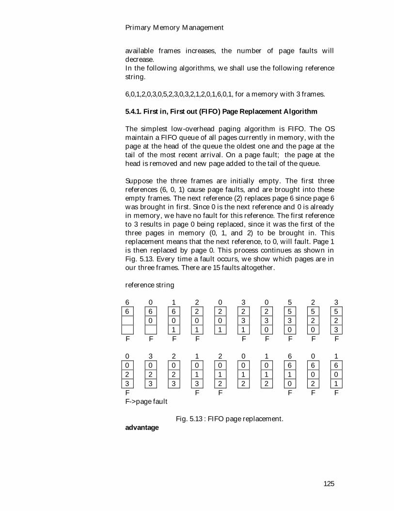
Primary Memory Management
125
available frames increases, the number of page faults will decrease. In the following algorithms, we shall use the following reference string. 6,0,1,2,0,3,0,5,2,3,0,3,2,1,2,0,1,6,0,1, for a memory with 3 frames. 5.4.1. First in, First out (FIFO) Page Replacement Algorithm The simplest low-overhead paging algorithm is FIFO. The OS maintain a FIFO queue of all pages currently in memory, with the page at the head of the queue the oldest one and the page at the tail of the most recent arrival. On a page fault; the page at the head is removed and new page added to the tail of the queue. Suppose the three frames are initially empty. The first three references (6, 0, 1) cause page faults, and are brought into these empty frames. The next reference (2) replaces page 6 since page 6 was brought in first. Since 0 is the next reference and 0 is already in memory, we have no fault for this reference. The first reference to 3 results in page 0 being replaced, since it was the first of the three pages in memory (0, 1, and 2) to be brought in. This replacement means that the next reference, to 0, will fault. Page 1 is then replaced by page 0. This process continues as shown in Fig. 5.13. Every time a fault occurs, we show which pages are in our three frames. There are 15 faults altogether. reference string 6 0 1 2 0 3 0 5 2 3 6 6 6 2 2 2 2 5 5 5 0 0 0 0 3 3 3 2 2 1 1 1 1 0 0 0 3 F F F F F F F F F 0 3 2 1 2 0 1 6 0 1 0 0 0 0 0 0 0 6 6 6 2 2 2 1 1 1 1 1 0 0 3 3 3 3 2 2 2 0 2 1 F F F F F F F->page fault
Fig. 5.13 : FIFO page replacement. advantage

Operating System
126
It is easy to understand and program.
disadvantage
Its performance is not always good. It could contain a heavily used variable which was
initialized very early and is in constant use. A bad replacement choice increases the page fault rate and
shows the program execution.
Belady's Anomaly We know that the more page frames of the memory causes fewer page faults. But it is not always true. In 1969, Belady et al discovered an example, in which FIFO caused more page faults with four page frames than with three. This is unexpected and known as Belady's anomaly. Belady's anomaly reflect the fact that the page fault rate may increase as the number of allocated frames increases. The following example will clarify this fact. Consider Reference String 0 1 3 4 0 1 5 0 1 3 4 5
From the Fig. 5.14 you see the 9 page faults and the FIFO with 4 frames causes 10 faults. Note that F denote page faults. All pages frames initially empty 0 1 3 4 0 1 5 0 1 3 4 5 1st page 0 1 3 4 0 1 5 5 5 3 5 5 0 1 3 4 0 1 1 1 5 3 3 last page 0 1 3 4 0 0 0 1 5 5 F F F F F F F F F
9 Page faults
(a) FIFO with three page frames.
0 1 3 4 0 1 5 0 1 3 5 5 1st page 0 1 3 4 4 4 5 0 1 3 4 5 0 1 3 3 3 4 5 0 1 3 4 0 1 1 1 3 4 5 0 1 3 last page 0 0 0 1 3 4 5 0 1 F F F F F F F F F F
10 Page faults (b) FIFO with four page frames.
Advantage
Disadvantage

Primary Memory Management
127
Fig. 5.14 : Belady's anomaly.
5.4.2. Optimal Replacement An optimal page replacement algorithms has the lowest page fault rate of all algorithm. It would never suffer from Belady's anomaly. It has been called OPT or MIN. It replaces that page which will not be used for the longest period of time. Consider the following reference string 6,0,1,2,0,3,0,5,2,3,0,3,2,1,2,0,1,6,0,1, for a memory with 3 frames. The first three references cause faults which fill the empty frames. The reference to page 2 replaces page 6 because 6 will not be used until reference 18, while page 0 will be used at 5, and page 1 at 14. The reference to page 3 replaces page 1, since page 1 will be the last of the three pages in memory to be referenced again. So, in this algorithm there are nine faults together. With only nine page faults, optimal replacement is much better than FIFO, which had fifteen faults Fig. 5.15. reference string 6 0 1 2 0 3 0 5 2 3 6 6 6 2 2 2 2 2 2 2 0 0 0 0 0 0 5 5 5 1 1 1 3 3 3 5 3 F F F F F F 0 3 2 1 2 0 1 6 0 1 2 2 2 2 2 2 2 6 6 6 0 0 0 0 0 0 0 0 0 0 3 3 3 1 1 1 1 1 1 1 F F F
Fig. 5.15 : Optimal page replacement. disadvantage
It is difficult to implement since it requires future know ledge of the reference string.
It is within 12.3% of optimal at worst and 4.7% on average.
advantage
It has the lowest fault rate of all algorithm.

Operating System
128
The key distinction between FIFO and OPT is that FIFO uses the time when a page was brought into memory; OPT uses the time when a page is to be used. 5.4.3. Least Recently used Page Replacement Algorithm A good approximation to the optimal algorithm is based on the observation pages that have been heavily used in the last few instructions will probably be heavily used again in the next few. Pages that have not been used for ages will probably remain unused for a long time. This idea suggest a realizable algorithm : when page fault occurs, replace the page that has been unused for the longest time. This technique is called LRU algorithm. In the following Fig. 5.16, LRU produces twelve faults. Notice that the first five faults are the same as the optimal replacement. When the reference to page 5 occurs, however, LRU sees that of the three frames in memory, page 2 was used least recently. The most recently used page is page 0, and just before that page 3 was used. Thus LRU replaces page 2, not knowing that it is about to be used. When it then faults for page 2, LRU replaces page 3 since of the three pages in memory {0, 3, 5}, page 3 is the least recently used. Despite these problems, LRU with twelve faults is still much better than FIFO with fifteen. reference string 6 0 1 2 0 3 0 5 2 3 6 6 6 2 2 2 2 5 5 5 0 0 0 0 0 0 0 0 3 1 1 1 3 3 3 2 2 F F F F F F F F 0 3 2 1 2 0 1 6 0 1 0 0 0 1 1 1 1 1 1 1 3 3 3 3 3 0 0 0 0 0 2 2 2 2 2 2 2 6 6 6 F F F F F->page faults
Fig. 5.16 : Least recently used page replacement.
Distinction between FIFO and OPT.
Primary Memory Management
129
advantage
It is considered to be quite good. It does not suffer from Belady's anomaly
disadvantage
It is not easy to implement It is complex to determine on order for the frames defined
by the time of last use.
5.5. Exercise 5.5.1. Multiple choice questions 1. How do we choose a particular replacement algorithm? i) The algorithm with lowest page fault rate ii) Highest fault rate iii) Medium fault rate iv) None of the above. 2. As the number of available frame increases, the number of
page fault i) increases ii) decreases iii) does not change iv) none of the above. 5.5.2. Questions for short answers a) What do you understand by virtual memory? b) Consider the following page replacement algorithms :
LRU, FIFO, Optimal. i) Rank these algorithm from bad to perfect according to
their page fault rate. ii) Separate those algorithms which suffer from Belady's
anomaly from those which do not. c) When do page faults occur? d) What do you understand by pages and page frames? e) What do you know about page replacement? f) What are the problems that must be solved for
implementing demand paging?
Advantage

Operating System
130
5.5.3. Analytical questions a) Given that,
Particular computer has a maximum of three page frames, Executions requires access to 5 distinct pages, Given the following reference string 2 3 2 1 5 2 4 5 3 2 5 2 How many page faults there will be under i) LRU ii) OPT iii) FIFO
b) 6, 0, 1, 2, 0, 3, 0, 5, 2, 3, 0, 3, 2, 1, 2, 0, 6, 0, 1 for a memory
with three frames. Indicate how many page faults there will under i) LRU ii) FIFO.

Unit 6 : Secondary Storage Management Disk drives are important to the efficiency of today's OS for se in virtual memory and file systems. Disk drives are about four orders of magnitude slower than main memory. Most of the processing of modern computer systems centers on the disk system. Disks provide the primary on-line storage of information, both programs and data. Most programs, like compilers, assemblers, sort routines, editors, formatters, and so on, are stored on a disk until loaded into memory, and then use the disk as both the source and destination of their processing. So the proper management of disk storage is of central importance to a computer system. Lesson 1 : Introduction to Disk 1.1. Learning Objectives On completion of this lesson you will be able to know : what a disk is disk organization access mechanism of disk. 1.2. Characteristics of Disk Disk is the magnetic medium on which the computer records information. Disks represent the most common form of computer storage. Disk have three major advantages over using main memory :
storage capacity available is much larger price per bit is much lower information’s is not lost when the power is turned off.
A disk is divided into tracks. Data stored in concentric circle is known as tracks. The number of tracks varies from disk drive to disk drive. Each track is further divided into sectors. A sector is the smallest unit of information which can be read from or written to the disk. All sectors contain the same number of bytes . Large disk systems may have several platter Fig. 6.1.

Operating System
132
Fig. 6.1 : Moving head disk mechanism. Each platter has two surfaces. To access a sector we must specify the surface, track, and sector. The read/write heads are moved to the correct track (seek time), electronically switched to the correct surface, and then we wait (latency time) for the requested sector to rotate below the heads. A cylinder is a set of tracks which are the same track position of the disk but on different platter surfaces. No seek is necessary for accessing tracks in the same cylinder. When the disk is in use, a drive motor spins it at high speed (for example, 3600 revolutions per minute). There is a read/write head positioned just above the surface of the disk. The disk surface is logically divided into tracks. Information is stored by recording it magnetically on the track under the read/write head. There may be hundreds of tracks on a disk surface. A fixed-head disk has a separate head for each track that arrangement allows the computer to switch from track to track quickly, but it requires a large number of heads, making the device very expensive. The moving-head disk requires hardware to move the head, but only a single head is needed, which moves in and out to access different track, resulting in a much cheaper system. The hardware for a disk system can be divided into two parts. The disk drive is the mechanical part, including the device motor, the read/write heads, and associated logic. The other part, called the disk controller, determines the logical interaction with the
Disk hardware

Secondary Storage Management
133
computer. The controller takes instructions from the CPU and orders the disk drive to carry out the instruction. Information on disk is referenced by a multi-part address, which includes the drive number, the surface and the track. All of the tracks on one drive that can be accessed without moving the heads. Within a track, information is written in blocks. The blocks may be a fixed size, specified by the hardware. These are called sectors. Each sector can be separately read or written. Disk head seek optimization strategies are one mechanism used to improve the efficiency of disk I/O. The time taken for a disk drive to satisfy a request consists of seek time, latency time and transfer time. To access a block on the disk, the system must first move the head to the appropriate track or cylinder. This head movement is called a seek, and the time to complete it is seek time. Once the head is at the right track, it must wait until the desired block rotates under the read/write head. This delay is latency time. Transfer time is the time of data between the disk and main memory can take place. The total time to service a disk request is the sum of the seek time, latency time, and transfer time. Since most jobs depend heavily upon the disk for loading and input and output files, it is important that disk service be as fast as possible. The operating system can improve on the average disk service time, and transfer time. A disk service requires that the head moved to the desired track. Then a wait for latency and finally the transfer of data. The purpose of disk head seek optimization is as follows :
Largest proportion of time for most reads is taken up in seek time.
There will be a queue of disk requests for the disk drive to satisfy.
If these requests can be scheduled to minimize seek time it should drastically reduce the amount of time to fulfill disk requests.
Disk scheduling policies schedule sector access to minimize seeking.
For example, Read a file of 256 sectors from a disk drive with the following characteristics. average seek time = 20 msec
Rotational latency : Wait for the correct block to be under the head.
Seek time : Time to move disk arm to required track.
Transfer time: Time to transfer a sector between the disk and the memory buffer.
The purpose of disk head seek optimization.
Operating System
134
transfer rate = 1 Mb/s sectors = 512 bytes 32 sectors per track. Consider two cases
file is stored contiguously over 8 tracks file is stored randomly all over disk.
File is stored contiguously
Time to read one track is seek + latency + data transfer = 20 msec + 8.3 msec + 7*25 = 220 msec
Randomly Stored
Time to read one sector = 28.8 msec Time to read 256 sectors = 7.37 seconds 1.3. Exercise
1.3.1. Multiple choice questions
1. Seek time is the time
i) to move disk arm to required track. ii) spent waiting for the correct block to be under the head. iii) to transfer a sector between the disk and memory buffer. iv) none of the above.
2. The hardware for a disk system can be divided into
i) two parts ii) 3 parts iii) 4 parts iv) 5 parts.
1.3.2. Questions for short answers
a) What is a disk? What are the advantages of disk over main memory?
b) Describe disk organizations. c) Define tracks, sectors, platter, cylinder. d) What do you understand by fixed head disk and moving
head disk? e) What are the disadvantages of using fixed head disk? f) What are the advantages of using moving head disk? g) Explain how to access a block on the disk? h) Define transfer time, seek time and latency time.

Secondary Storage Management
135
Lesson 2 : Disk Scheduling Algorithm 2.1. Learning Objectives On completion of this lesson you will be able to know : different types of disk scheduling algorithms. 2.2. Disk Scheduling Algorithms Random sector causes poor performance. Sector access must be scheduled to minimize seeking. Typically there will be multiple I/O requests queued for each disk. In this lesson we will discus the issues of disk drive performance. The seek time dominates for the most of the disks, so reducing the mean seek time can improve system performance substantially. So, for improving the system performance different types of disk scheduling algorithm are used. Some of these are :
First come first served scheduling (FCFS) Shortest-Seek-Time-First Scan.
At first we will discuss about FCFS. 2.2.1. First Come First Served Scheduling (FCFS) First-Come-First-Served (FCFS) scheduling is the simplest form of disk scheduling algorithm. Consider a disk in which a request comes in to read on track 54, while the seek to track 54, is in progress new request comes in for tracks 96, 171, 35, 118, 12, 120, 60, and 62 in that order. We already know that the read/write head is initially at track 54. So, it will first move from 54 to 96, then 96 to 171 and then to 35, 118, 12, 120, 60, and 62. This algorithm would require head movement of 42, 75, 136, 83, 106, 108, 60 and 2 respectively, for a total of 612 tracks. This schedule is diagrammed in the Fig. 6.2. advantage of FCFS
Easy to program Intrinsically fast.

Operating System
136
disadvantage of FCFS
It may not provide the best average service. Head starts at track 54 12 35 54 60 62 96 118 120 171
Fig. 6.2 : First-Come-First served disk scheduling. The problem of this algorithm is the wild swing from 118 to 12 and then back to 120. If the requests for tracks 35 and 12 could be serviced together, before or after the requests at 118 and 120, the total head movement could substantially decreased and the average time to service each request would decrease, improving disk throughput. 2.2.2. Shortest Seek Time First (SSTF) SSTF selects the request with minimum seek time from the current head position. Since seek time is generally proportional to the track difference between the requests, this approach is implemented by moving the head to the closest track in the request queue. For our example request queue, the closest request to the initial head position 54 is at track 60. Once we are at track 60, the next closest request is at track 62. At this point, the distance to track 35 is 27, while the distance to 96 is 34. Therefore the request at track 35 is closer and is served next. Continuing, we service the request at track 12, then 96, 118, 120 and finally at 171 (Fig.6.3). This schedule is diagrammed in this following Fig. 6.3. This scheduling method in a would require head movement of 6, 2, 27, 23, 84, 22, 2, and 51 respectively, for a total of only 217 tracks, a

Secondary Storage Management
137
little more than a third of the distance needed for FCFS. This algorithm would result in a substantial improvement in average disk service. Head starts at track 54 12 35 54 60 62 96 118 120 171
Fig. 6.3 : Shortest Seek Time First Scheduling.
SSTF may cause starvation of some requests suppose we have two requests in the queue, for 12, and 173. If a request near 12 arrives while we are servicing that request, it will be serviced next, making the request at 173 wait. While this request is being serviced, another request close to 12 could arrive. So, a continual stream of requests near each other could arrive, causing the request for track 173 to wait indefinitely. The SSTF algorithm, is not optimal but a substantial improvement over FCFS. For example, if we move the head from 54 to 35 even though it is not closest, and then to 12 before turning around to service 60, 62, 96, 118, 120 and 171 we can reduce the total head movement to 201 tracks. 2.2.3. SCAN In the SCAN algorithm, the read/write head or disk arm moves in one direction, performing all requests until no more are needed in that direction and then turns around and comes back. The head continuously scans the disk from end to end. Before applying SCAN to this example, 96, 171, 35, 118, 12, 120, 60, 62, and 67
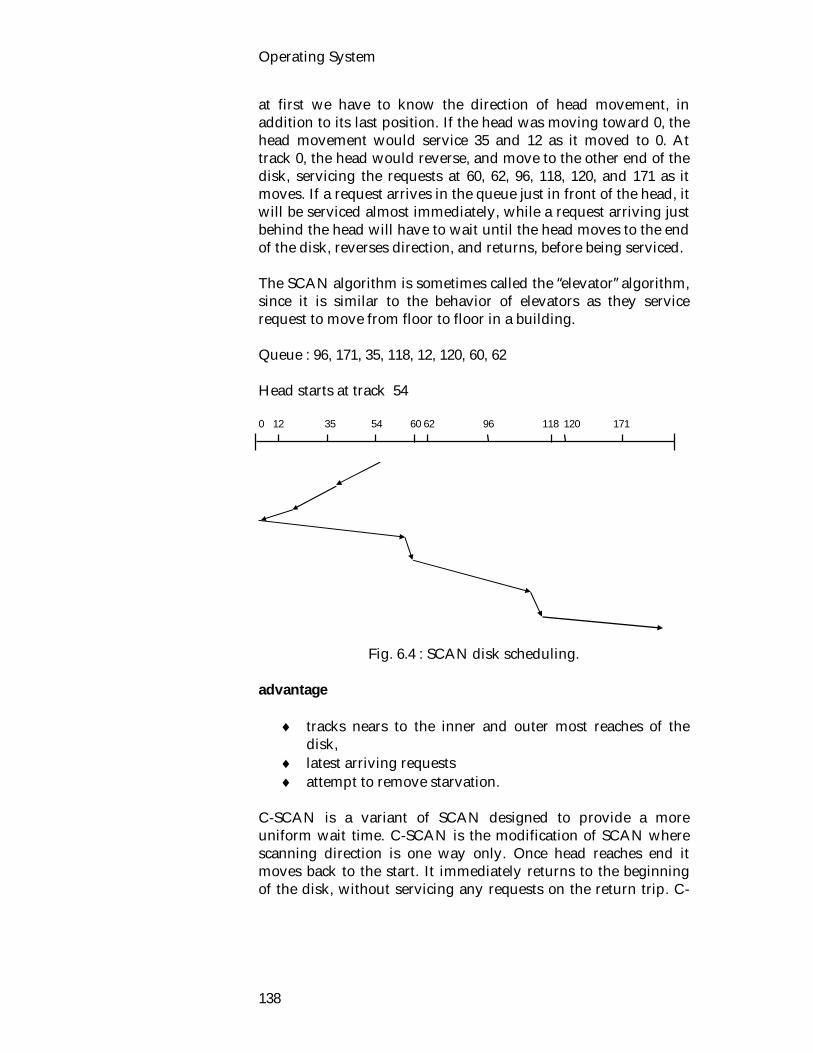
Operating System
138
at first we have to know the direction of head movement, in addition to its last position. If the head was moving toward 0, the head movement would service 35 and 12 as it moved to 0. At track 0, the head would reverse, and move to the other end of the disk, servicing the requests at 60, 62, 96, 118, 120, and 171 as it moves. If a request arrives in the queue just in front of the head, it will be serviced almost immediately, while a request arriving just behind the head will have to wait until the head moves to the end of the disk, reverses direction, and returns, before being serviced. The SCAN algorithm is sometimes called the “elevator” algorithm, since it is similar to the behavior of elevators as they service request to move from floor to floor in a building. Queue : 96, 171, 35, 118, 12, 120, 60, 62 Head starts at track 54 0 12 35 54 60 62 96 118 120 171
Fig. 6.4 : SCAN disk scheduling. advantage
tracks nears to the inner and outer most reaches of the disk,
latest arriving requests attempt to remove starvation.
C-SCAN is a variant of SCAN designed to provide a more uniform wait time. C-SCAN is the modification of SCAN where scanning direction is one way only. Once head reaches end it moves back to the start. It immediately returns to the beginning of the disk, without servicing any requests on the return trip. C-

Secondary Storage Management
139
SCAN essentially treats the disk as of it were circular, with the last track adjacent to the first one. In SCAN and C-SCAN the head is only moved as far as the last request in each direction. As soon as there are no requests in the last request, the head movement is reversed. These types of SCAN and C-SCAN are called LOOK and C-LOOK. Queue : 96, 171, 35, 118, 12, 120, 60, 62 Head starts at track : 54 12 35 54 60 62 96 118 120 171
Fig. 6.5 : C-LOOK disk scheduling.
2.3. Selecting a Disk Scheduling Algorithm When there are so many disk scheduling algorithms, how is it possible to choose a particular algorithm? SSTF is quite common and has a natural appeal. SCAN and C-SCAN are more appropriate for systems with a heavy load on the disk. It is possible to define an optimal algorithm, but the computation needed for an optimal schedule may not justify the savings over SSTF or SCAN. With any scheduling algorithm, however, performance depends heavily on the number and types of requests. In particular, if the queue seldom has more than one outstanding request, then all scheduling algorithms are effectively equivalent. FCFS is also a reasonable algorithm, when the queue have only one request.

Operating System
140
2.4. Exercise 2.4.1. Multiple choice questions 1. In scan algorithm if a request arrives in the queue just in
front of the head, it will i) be serviced later ii) be serviced immediately iii) have to wait iv) retain before being serviced. 2. C- SCAN is the modification of i) SCAN ii) SSTF iii) Look iv) all of the above. 2.4.2. Questions for short answers a) Why scan algorithm is called elevator algorithm? b) What do you know about scan algorithm? c) What do you know about C-SCAN and C-LOOK?
Illustrate with figure. d) What are the difference between disk scheduling and
elevator scheduling algorithm? e) Explain FCFS scheduling algorithm. 2.4.3. Analytical questions a) Given that it takes 1ms to travel from one track to the
next, and the arm is originally positioned at track 15 moving to ward the low-numbered tracks. Computes how long it will take to satisfy the following requests
4, 40, 11, 35, 7, 14 use the scan scheduling policy and ignore rotational time and transfer time; just consider seek time.
b) Suppose the head of a moving disk with 100 tracks numbered 0 to 99; is currently serving a request at track 71

Secondary Storage Management
141
and has just finished a request at track 63. If the queue of requests is kept in the FIFO order;
43, 73, 45, 89, 47, 75, 51, 88, 65 What is the total head movement to satisfy these requests for the following disk scheduling algorithm.
i) FCFS ii) SSTF iii) SCAN. c) Disk request come in to disk drive for tracks 15, 33, 25, 2,
55, 9 and 58 in that order. A seek takes 3 mscc per track moved. How much seek time is needed for
i) FCFS ii) SSTF iii) SCAN iv) C-SCAN.
Note that in all cases head starts at track 30.
Lesson 3 : Free Space Management

Operating System
142
3.1. Learning Objectives On completion of this lesson you will be able to know : sector queuing different types of free space management. 3.2. Sector Queuing Sector queuing is an algorithm for scheduling fixed-head devices. It is based on the division of each track into a fixed number of blocks called sectors. The disk address in each request specifies the track and sector. Since seek time is zero for fixed-head devices, the main service time is latency time. For FCFS scheduling, assuming that requests are uniformly distributed over all sectors, the expected latency is one-half of a revolution. Consider, an example. Assume that the head is currently over sector 3 and the first request in the queue is for sector 13. To service this request we must wait until sector 13 revolves under the read/write heads. If there is a request in the queue for sector 6, it could be serviced before the request sector 13, without causing the request for sector 13 to be delayed. Thus we can greatly improve our throughput by servicing a request for each sector as it passes under the head, even if the request is not at the head of the waiting queue. Sector queuing defines a separate queue for each sector of the drum. When a request arrives for sector n, it is placed in the queue for sector n in. As sector n rotates beneath the read/write heads, the first request in its queue is serviced. Sector queuing is primarily used with fixed-head devices. However, it can also be used with moving-head devices, if there is more than one request for service within a particular track of cylinder. Once the head is moved to a particular cylinder, all requests for this cylinder can be serviced without further head movement. Hence sector queuing can be used to order multiple requests within the same cylinder. As with other scheduling algorithms, of course, sector queuing will only have on effect if the operating system must choose from a set of more than one request. 3.3. Free Space Management

Secondary Storage Management
143
Files are normally stored on disk, some management of disk space is a major concern to file system designers. Since there is only a limited amount of disk space, it is necessary to reuse the space from deleted files for new files. To keep track of free disk space, the file system maintains a free space list. The free space list records all disk blocks which are free. A disk allocation table is used to keep track of blocks which are available. To create a file, we search the free space list for the required amount of space and allocate it to the new file. This space is then removed from the free space list. When a file is deleted, its disk space is added to the free space list. There are two techniques for free space management. These are
Bit map Chained free space list of disk.
3.3.1. Bit Map In bit map technique each free block is represented by one bit. Free block are represented by 1s in the map, and allocated block are represented by 0s. As for example, a disk where block 1, 3, 4, 5, 10, 11, 12, 13, 16, 17, 18, 27 are free the free space bit map would be 0101110000111100111000000001... The bit map method is preferable where enough main memory is available to hold the bit map. 3.3.2. Chained Free Space List of Disk The second technique is to link all the free disk blocks together, keeping a pointer to the first free block. This block contains a pointer to the next free disk block, and so on. So, we would keep a pointer to block 1, as the first free block. Block 3 would contain a pointer to block 4, which would point to block 5, which would point to block 10, which would point to block 11, which would point to be and so on (Fig. 6.6).
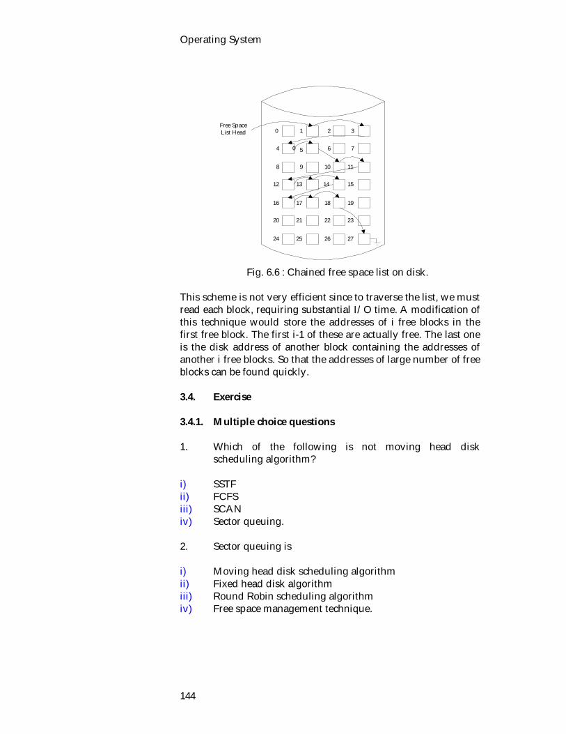
Operating System
144
Fig. 6.6 : Chained free space list on disk. This scheme is not very efficient since to traverse the list, we must read each block, requiring substantial I/O time. A modification of this technique would store the addresses of i free blocks in the first free block. The first i-1 of these are actually free. The last one is the disk address of another block containing the addresses of another i free blocks. So that the addresses of large number of free blocks can be found quickly. 3.4. Exercise 3.4.1. Multiple choice questions 1. Which of the following is not moving head disk
scheduling algorithm? i) SSTF ii) FCFS iii) SCAN iv) Sector queuing. 2. Sector queuing is i) Moving head disk scheduling algorithm ii) Fixed head disk algorithm iii) Round Robin scheduling algorithm iv) Free space management technique.
0 1
04
27
32
5
15
1098
76
17
20
13
16
12
24
19
23
14
11
21 22
18
25 26
Free SpaceList Head

Secondary Storage Management
145
3.4.2. Questions for short answers a) What do you understand by sector queuing? b) What do you understand by free space management? c) Describe bit map techniques? 3.4.3. Analytical questions a) Describe different types free space management
techniques.
Operating System
146
Lesson 4 : Allocation Methods 4.1. Learning Objectives On completion of this lesson you will be able to : describe different allocation methods list the advantage and disadvantage of indexed allocation know compacti on teachings. 4.2. Allocation Methods In the most cases, many files will be stored on the same disk. The main problem is how to allocate space to these files so that disk space is effectively utilized and files can be quickly accessed. There are three allocation methods and they are : Contiguous, linked, and indexed. Each method has its advantages and disadvantages. Accordingly, some systems support all three. More commonly, a system will use one particular method for all files. 4.2.1. Contiguous Allocation The contiguous allocation method requires each file to occupy a set of contiguous addresses on the disk. Disk addresses define a linear ordering on the disk. Contiguous allocation of a file is defined by the disk address of the first block and its length. The directory entry for each file indicates the address of the starting block and the length of the area allocated for this file Fig. 6.7. Thus Both sequential and direct access can be supported by contiguous allocation. It has two drawbacks.
1) The first difficulty is determining how much space is needed for a new file. Once the implementation of the free space list is defined, we can decide how to find space for a contiguously allocated file. This problem can be compared to dynamic storage allocation problem. Now let's look dynamics storage allocation problem.
Dynamic Storage Allocation Problem

Secondary Storage Management
147
Disk space is viewed as a linked list of free, used or allocated segments, each segment is a contiguous set of disk block or a hole. A hole is referred to as an unallocated segment. Dynamic storage allocation problem is how to satisfy a request from a list of free blocks. There are a number of strategies to solve this problem. Strategies Explanation Best fit First fit Next fit Worst fit
Segment placed in hole which is closest to segment size. Segment is placed in first hole it can fit it. Modification of first fit, starts looking at the place where the last search ended. A segment is placed into the largest possible hole.
Fig. 6.7 : Contiguous allocation.
Observation on Performance
Best fit usually performs the worst, since it leaves behind the smallest possible hole.
0 1
4
27
32
5
15
1098
76
17
20
13
16
12
24
19
23
14
11
21 22
18
25 26
Count
SST
DCA
List
Directory File Start Length
Count 0 3 SST 9 2
DCA 14 4 List 20 5

Operating System
148
First fit is simplest to implement and usually fastest and best.
Next fit is usually a little worse then first fit. 2) The second problem is external fragmentation. External
fragmentation exists when enough total disk space exists to satisfy a request, but it is not contiguous; storage is fragmented into a large number of small holes. Note that an unallocated segment is called a hole. This can be solved by compaction. Let's go through compaction.
Compaction External fragmentation problem can be solved by compaction scheme. In compaction scheme, the user copies the entire file system onto another floppy disk. The original floppy is then completely freed, creating one large contiguous free hole. The files can then be copied back onto the floppy, by allocating contiguous space from this one large hole. So compaction scheme effectively compacts all free space into one hole, solved the fragmentation problem. But it is time consuming. 4.2.2. Linked Allocation Linked allocation solves the external fragmentation and size declaration problem of contiguous allocation. In linked allocation, scheme, each file is a linked list of disk blocks; the disk blocks may be scattered anywhere on the disk. With linked allocation each directory entry has a pointer to the first disk block of the file. This pointer is initialized to nil, to signify an empty file. The directory contains a pointer to the first (and last) blocks of the file. For example, a file of 6 blocks which starts at block 4, might continue at block 8, then block 22, block 11, and block 13 and finally block 23 (Fig. 6.8). Creating a file is easy; we simply create a new entry in the device directory. A write to a file removes the first free block from the free space list and writes to it. This new block is then linked to the end of the file. To read a file, we simply read blocks by following the pointers from block to block.
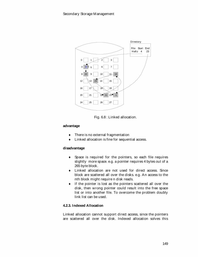
Secondary Storage Management
149
Fig. 6.8 : Linked allocation. advantage
There is no external fragmentation Linked allocation is fine for sequential access.
disadvantage
Space is required for the pointers, so each file requires slightly more space. e.g. a pointer requires 4 bytes out of a 265 byte block.
Linked allocation are not used for direct access. Since block are scattered all over the disks. e.g. An access to the nth block might require n disk reads.
If the pointer is lost as the pointers scattered all over the disk, then wrong pointer could result into the free space list or into another file. To overcome the problem doubly link list can be used.
4.2.3. Indexed Allocation Linked allocation cannot support direct access, since the pointers are scattered all over the disk. Indexed allocation solves this
8
22 13
23
-111
0 1
04
27
32
5
15
1098
76
17
20
13
16
12
24
19
23
14
11
21 22
18
25 26
File Start EndHafiz 4 23
Directory
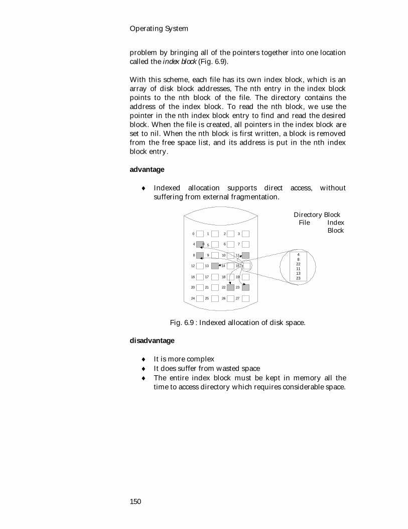
Operating System
150
problem by bringing all of the pointers together into one location called the index block (Fig. 6.9). With this scheme, each file has its own index block, which is an array of disk block addresses, The nth entry in the index block points to the nth block of the file. The directory contains the address of the index block. To read the nth block, we use the pointer in the nth index block entry to find and read the desired block. When the file is created, all pointers in the index block are set to nil. When the nth block is first written, a block is removed from the free space list, and its address is put in the nth index block entry. advantage
Indexed allocation supports direct access, without suffering from external fragmentation.
Fig. 6.9 : Indexed allocation of disk space. disadvantage
It is more complex It does suffer from wasted space The entire index block must be kept in memory all the
time to access directory which requires considerable space.
0 1
04
27
32
5
15
1098
76
17
20
13
16
12
24
19
23
14
11
21 22
18
25 26
48
22111323
Directory Block File Index
Block

Secondary Storage Management
151
4.3. Exercise 4.3.1. Multiple choice questions 1. Three major methods of allocating disk space are i) contiguous, linked and indexed. ii) sequential, indexed and indexed sequential. iii) sequential, free space management and noncontiguous. 2. Best fit refers to the i) allocation of the smallest hole that is big enough. ii) allocation of the largest hole. iii) allocation of the first hole that is big enough. 4.3.2. Questions for short answers a) What are problems in contiguous allocation method? b) What do you understand by contiguous dynamic storage
allocation problem? How can it be solved? c) What are the strategies to solve dynamic allocation
problem? d) Explain external fragmentation. How can it be solved? 4.3.3. Analytical questions a) Describe contiguous allocation scheme. b) i) Explain linked allocation of disk space.
ii) List the advantages and disadvantages of this scheme.

Operating System
152
Unit 7 : File Management The most visible part of an operating system is the file system. Files store data and programs. A file system is a collection of files and directories, plus operation on them. The operating system implements the abstract concept of a file by managing storage devices, such as tapes and disks. In the following lesson, we will look file organization, operation, access method, protection and security. Lesson 1 : File Organization and File
Systems 1.1. Learning Objectives On completion of this lesson you will be able to know: what a file system is the objectives and requirements of a file system file system architecture different file organization methods what directories are. 1.2. File At first we shall know what a file is. A file is a collection of related information defined by its creator. Commonly, files represent programs (both source and object forms) and data. Data files may be numeric, alphabetic or alphanumeric. File may be free form, such as text files, or may be rigidly formatted. In general, a file is a sequence of bits, bytes lines or records whose meaning is defined by its creator and user. A file is an abstract data type defined and implemented by the operating system. A file is a sequence of logical records. A logical record may be a byte, a line (fixed or variable length) of a more complex data item. The operating system may specifically support various record types or may leave that to the application program. A file is named, and is referred to be its name. It has certain other properties such as its type, the time of its creation, the name (or account number) of its creator, its length and other file attributes.
A file is a collection of related information defined by its creator.

Operating System
154
A file has a certain defined structure according to its use. A text file is a sequence of characters organized into lines (and possibly pages); a source file is a sequence of subroutines and functions, each of which is further organized as declarations followed by executable statements; an object file is a sequence of words organized into loader record blocks. 1.3. File Attributes and Operations Filenames and data are not the only things associated with each file, but all OS associate other information with each file e. g. date and time the file was created, file size etc. These extra items are called file's attributes. The following table summarizes some of the attributes associated with files. Attribute Meaning Protection who can access and how password password required for access creator id of file creator owner id of current owner various flags read-only, hidden, system, archive,
ASCII/binary random access, temporary, lock
record length bytes per record key position and length info to find key within a record creation/modification time
date and time
current size file size in bytes
Table 7.1 : File attributes. File Operation The file system is implemented by operating system. Files exist to store information and allow it to be retrieved later. Different systems provide different operations to allow storage and retrieval. System calls are provided to support different file operation. Let’s look some of the file operations :
File attributes
File operation

File Management
155
Operation Purpose create make empty file delete remove file open ready a file for access close tidy up file after finished accessing read read data from current position append add data to the end of the file seek move current position to specified position
(random access) get attributes obtain the file's attributes set attributes modify the file's attributes rename change the name
Table 7.2 : File operations.
1.4. File Systems The collection of algorithms and data structures which perform the translation from logical file operations (system calls) to actual physical storage of information. Objectives of a File System Include
Provide data storage/ manipulation. Guarantee consistency of data and minimize errors. Optimize performance (system and user). Support variety of I/O devices and provide standard
system call interface. Support multiple users.
Requirements to be Fulfilled by a File System
User ability to create, delete, change files. Controlled access to other user's files. User controls access to their files. User can restructure files as appropriate. Users should be able to back up and recover files. Users should have access to files via a symbolic name.
The File System Architecture
The file system is generally layered.
Objectives of a file system.
Requirements

Operating System
156
It is built upon the standard I/O device management schemes.
The following is a general representation intended to provide some overview of the concepts involved. The User : The user access the file system through programs which in turn use system calls. System Utilities : Commands like CP MV etc. programs that are supplied with the operating system but are not part of the kernel. Like all programs the system utilities use system calls to access the services provided by the operating system (and the file system). System Calls : The set of functions that allow programs access the services provided by the operating system. These include the services provided by the file system. Logical I/O System : This is what is usually referred to as the file system. The files system translates the logical file operations requested by uses via system calls into instructions to the basic I/O supervisor level. The file system maintains data structures that help it find out which files are in which directories and where they are located on disk.
The Layers of the File System
The Kernel of the Operating System
The User
System Utilities cd mkdir
Basic I/O Supervisor
Physical I/O System
Device Drivers
Actual Devices
Logical I/O System
System Calls open read close
The File system
The Layers of the File System.

File Management
157
Basics I/O Supervisor
OS portion responsible for managing the I/O devices. Including managing devices, I/O buffers and scheduling
decisions. Physical I/O Level Concerned with the placement of blocks onto devices. Device Drivers Communicates directly with the physical devices. 1.5. File Implantation There are two different organization. 1.5.1. File Organization Internal file structure according to access method of contents. (Logical Organization). 1.5.2. Physical Organization Placement and tracking of file contents on physical device. (looked at later). Organization Criteria
rapid access ease of update economic storage simple maintenance reliability.
Importance of criteria will vary according to circumstance and will not be necessary in all situations. Examples of File Organizations There are three general organization strategies used by operating systems. These are as follows : Byte Organization (none)
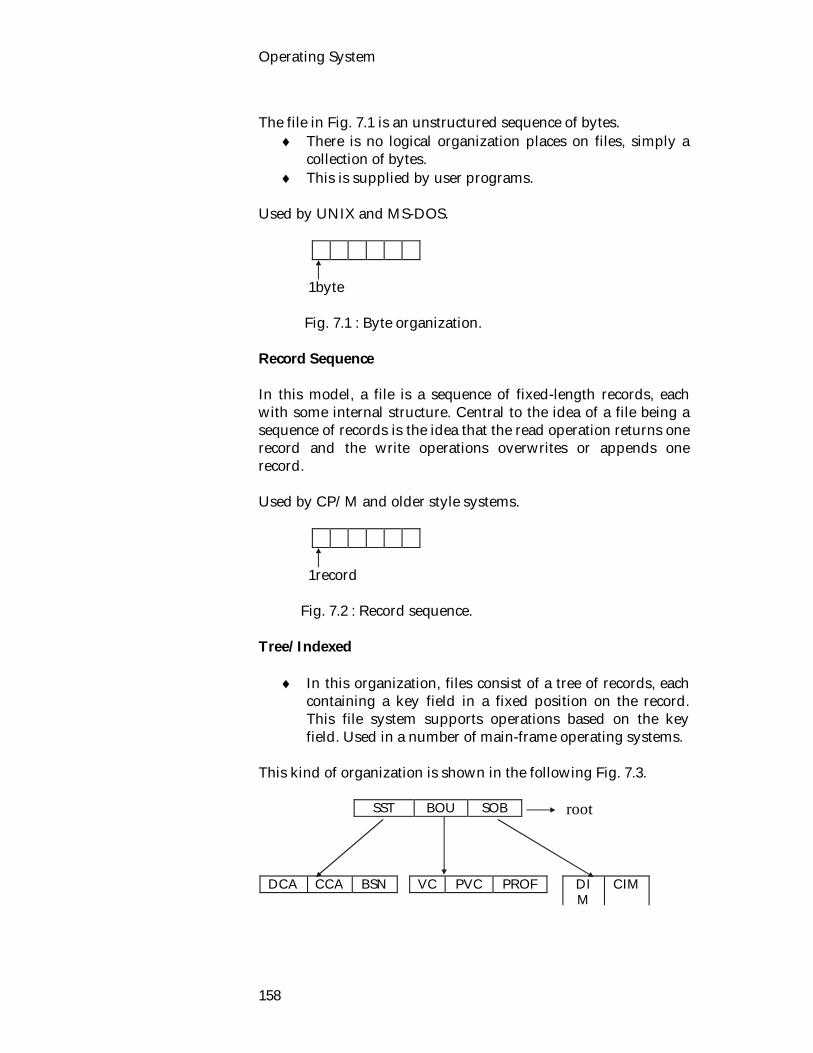
Operating System
158
The file in Fig. 7.1 is an unstructured sequence of bytes.
There is no logical organization places on files, simply a collection of bytes.
This is supplied by user programs. Used by UNIX and MS-DOS.
1byte Fig. 7.1 : Byte organization. Record Sequence In this model, a file is a sequence of fixed-length records, each with some internal structure. Central to the idea of a file being a sequence of records is the idea that the read operation returns one record and the write operations overwrites or appends one record. Used by CP/M and older style systems.
1record Fig. 7.2 : Record sequence. Tree/ Indexed
In this organization, files consist of a tree of records, each containing a key field in a fixed position on the record. This file system supports operations based on the key field. Used in a number of main-frame operating systems.
This kind of organization is shown in the following Fig. 7.3.
SST BOU SOB
DCA CCA BSN
VC PVC PROF
DIM
CIM
root

File Management
159
Fig. 7.3 : Tree organization.
1.6. Directories Special file type used to organize and contain other files. Directories typically owned by the file system and user's must access it's information through specific system utilities /calls. To keep track of files, the file system normally provides directories, which in many systems, are themselves files. A directory typically contains a number or entries. The following is a list of some of the information which may be kept in a directory entry. But this information varies form operating system to operating system. Some of the information is as follows :
File name : The symbolic file name. File type : For those systems which support different types. Location : A pointer to the device and location on that
device of the file. Size : The current size of the file (in bytes, words or blocks)
and the maximum allowed size. Current position : A pointer to the current read or write
position in the file. Protection : Access control information of control reading
writing, executing and so on. Usage count : Indicating the number of processes which are
currently using (have opened) this file. Time, date and process identification : This information may
be kept for (a) creation, (b) last modification, and (c) last use. These can be useful for protection and usage monitoring.
The operations which are to be performed on directory is as follows : Search : We used to be able to search a directory structure to find the entry for a particular file. Create file : New files needed to be created and added to the directory. Delete file : When a file is no longer needed, we want to remove it from the directory.
Operation of directory

Operating System
160
List directory : We need to be able to list the files in a directory and the contents of the directory entry for each file in the list. Backup : It's a idea to save the contents and structure of the file system at regular intervals. 1.7. Exercise 1.7.1. Multiple choice questions 1. Password and protection are i) file attributes ii) file operation iii) file organization iv) file architecture. 2. A text file is a sequence of i) characters organized into lines. ii) subroutines into lines. iii) words organized into loader record blocks. iv) None of the above. 1.7.2. Questions for short answers a) (i) What is a file system? (ii) What are its responsibilities? b) What are the objectives and requirements of a file system? c) What is it's structure and contents? d) How are files organized? e) List some of the operation of file system. f) What do you understand by file attributes? List some of
the file attributes. 1.7.3. Analytical questions a) Describe file system architecture.

File Management
161
Lesson 2 : File Access Methods 2.1. Learning Objectives On completion of this lesson you will be able to know: types of file access methods sequential access method direct access method combined file access method. 2.2. Access Method Files store information. This information must be accessed and read into memory. There are several ways that information in the file can be accessed. In the following section we will look at two file access method : sequential, and direct access. 2.2.1. Sequential Access The simplest access method in the sequential access. In this method, a process could read all the bytes or records in a file in order, starting at the beginning but could not skip around and read them out of order. A sequential file is organized so that one record follows another in some fixed succession or order. To access a particular record it is necessary to search through the file from the beginning until the desired item is reached. Also, new records can be added only at the end. The following Fig. 7.4 , clearly illustrate sequential access method. beginning Current position end
rewind read or write
Fig. 7.4 : Sequential access file. We know that most of the operations on a file are reads and writes. A read reads the next portion of the file and automatically

Operating System
162
advances the file pointer. A write appends to the end of file and advances to the end of the newly written material. Such a file can be rewound they can be read as often as needed. This method is convenient tape, rather than disk. The maintenance of sequential files involves keeping them sorted in the proper order and keeping the records up to date. Additions, deletions, and changes to be made are known as transactions and are temporarily batched into transaction files. Transaction files are sorted, then merged at regularly scheduled intervals with the files to be updated, known as master files. Sequential files are often used for payroll, billing and statement preparation, and for check processing by banks. Some of the advantages of sequential files include the following
Sequential files have simple organizational principle. Sequential files have a range of applications. Sequential files are an efficient storage method if a large
number of records are to be processed. Sequential file are inexpensive to use. Magnetic tape is not
a costly medium. Disadvantages
Sequential master files must be completely processed and new ones created every time records are updated.
Sequential files must usually be kept sorted. Sequential files are hard to keep current. Sequential files cannot be accessed directly.
2.2.2. Direct Access Direct access is based upon a disk model of a file. This method allows arbitrary bytes/ records to be read or written. In direct access file, records are stored on a direct access medium e.g. a disk, according to their addresses, which are often determined by hashing or hash function. If the address of a record is known, that record can be accessed directly without going through the records preceding it i.e. records can be accessed in any order. The address or location is determined, by hash function from the record itself. The hash function has two uses.
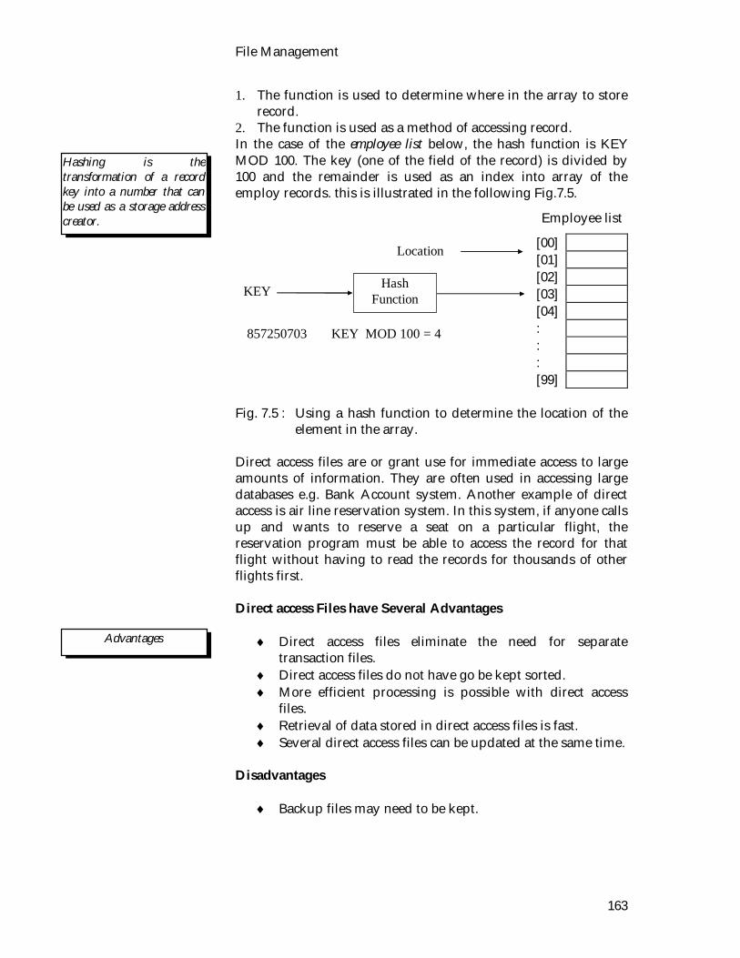
File Management
163
1. The function is used to determine where in the array to store record.
2. The function is used as a method of accessing record. In the case of the employee list below, the hash function is KEY MOD 100. The key (one of the field of the record) is divided by 100 and the remainder is used as an index into array of the employ records. this is illustrated in the following Fig.7.5.
[00] [01] [02] [03] [04] : : : [99]
Fig. 7.5 : Using a hash function to determine the location of the
element in the array. Direct access files are or grant use for immediate access to large amounts of information. They are often used in accessing large databases e.g. Bank Account system. Another example of direct access is air line reservation system. In this system, if anyone calls up and wants to reserve a seat on a particular flight, the reservation program must be able to access the record for that flight without having to read the records for thousands of other flights first. Direct access Files have Several Advantages
Direct access files eliminate the need for separate transaction files.
Direct access files do not have go be kept sorted. More efficient processing is possible with direct access
files. Retrieval of data stored in direct access files is fast. Several direct access files can be updated at the same time.
Disadvantages
Backup files may need to be kept.
Hashing is the transformation of a record key into a number that can be used as a storage address creator.
Hash Function KEY
857250703 KEY MOD 100 = 4
Location
Advantages
Employee list
Operating System
164
Direct access files show greater potential for accidental data destruction and security breaches.
Available storage space may be used less efficiently with direct access files than with sequential files.
Complex hardware and software are needed to implement direct access files.
2.2.3. Combined Approach Not all system support both sequential and direct access for files. Some systems allow only sequential file access; other allow only direct access. Some system allow indexed sequential file access method which combines the best features of the sequential file and the direct access file. They employ an index to store the locations of selected records. Its applications include inventory files used by different departments and customer billing files, used for credit check. Indexed sequential files have the following advantages.
Indexed sequential files are well suited to both batched and individual transactions.
With indexed sequential files, access to any particular record is faster than sequential files.
Disadvantage
Access is not as rapid as with direct access file. Some extra storage space is required to hold the index. Complex hardware and software are required to
implement indexed sequential files.

File Management
165
2.3. Exercise 2.3.1. Multiple choice questions 1. Records are stored according to their addresses in i) sequential access. ii) direct access. iii) indexed sequential access. iv) none of the above. 2. Direct access is based upon i) a disk model of a file. ii) a memory model of a computer. iii) byte sequence of a file. iv) none of the above. 2.3.2. Questions for short answers a) What are advantages and disadvantages of sequential
access? b) What do you know about direct access? What are the uses
of hash function? c) List some of advantages and disadvantages of direct
access. d) What are advantages of combined approach? e) What are the uses of sequential and direct access file? 2.3.3. Analytical question 1. Describe different file access methods.

Operating System
166
Lesson 3 : Security 3.1. Learning Objectives On completion of this lesson, you will be able to know: what security is security threats some of the better known penetration attempts security policies and mechanism. 3.2. Security File systems often contain information that is highly valuable to their uses. Protecting this information against unauthorized usage is therefore a major concern of all file system. In the following we shall look at a variety of issue related security. Security describes the combination tools, resources and administrative protect design to practices computing data and services. The word security encompasses a set of measures taken to guard against theft, attack, crime, and espionage or sabotage. Security implies the quality or state of being secure, that is, a relief from exposure to danger and acting so as to make safe against adverse contingencies. Unauthorized access, revelation, or destruction of data can violate individual privacy. Corruption of business data can result in significant and potentially catastrophic losses to companies. It is worth remembering, however, that security threats are not unique to computers. They are inevitably present in any form of safeguarding of valuable assets. Computer systems and software designs should address the legitimate security concerns and incorporate appropriate safeguards and mechanisms for enforcement of security policies. Security measures can increase cost and restricts the usefulness, user-friendliness, and performance of computer systems. The computer is only a part of the overall security system. Therefore, definition of the appropriate security policies is best
Advantages

File Management
167
left to data owners and application developers. The computer, and especially the operating system, should concentrate on providing a flexible and functionally complete set of security mechanisms so that the chosen security policies can be enforced effectively. 3.3. Security Threats The major security threats perceived by users and providers of computer-based systems include: Unauthorized disclosure of information Disclosure of information to unauthorized parties can result in breach of privacy and in both tangible and intangible losses to the owner of the information. Revelation of a credit card number, a proprietary product design, a list of customers, a bid on a contract, or strategic military data can be used by adversaries in numerous ways. Depending on the nature of the information in question, the consequences of abuse can range from inconvenience to catastrophic losses. Unauthorized alteration or destruction of information The undetected altering or destruction of information that cannot be recovered is potentially equally dangerous. Even without external leakage, the loss of vital data can put a company out of business. One known incidence of destruction involved a disgruntled employee who mislabeled the only copy of backup tapes as scratch, which led to their subsequent erasure. Unauthorized use of service Unauthorized use of a service can result in the loss of revenue to the service provider. Like most other forms of system penetration, it can be exploited to gain illegal access to information. Even benevolent penetration can bring bad publicity and deter potential customers. Denial of service to legitimate users Denial of service usually implies some form of impairing of the computer system that results in partial or complete loss of service to its legitimate customers. One form of denial of service comes in

Operating System
168
the form of programs that multiply and spread themselves, called computer worms. Goal : The goal of computer security is to guard against and eliminate potential threats. In particular, a secure system should maintain the integrity, availability, and privacy of data. That is, the data maintained by the system should be correct, available, and private. 3.4. Penetration Attempts There are numerous ways in which penetration of a computer system may be attempted. Some of the better-known penetration attempts are : Logged-on terminal : The terminal is left unattended by the
user. An intruder can access the system with full access to all data available to the legitimate user whose identity is assumed.
Passwords : Passwords used to authenticate users may be obtained by intruders for the purposed of illegal access in a number of ways, including guessing stealing, trial and error. or knowledge of vendor-supplied passwords used for systems generation and maintenance.
Browsing : Often, users may be able to uncover information that they are not authorized to access simply by browsing through the system files. In many systems there are files with improperly or overly permissively set access controls.
Trap doors : These are the secret points of entry without access authorization. They are sometimes left by software designers, presumably to allow them to access and possibly modify their programs after installation and production use. Trap doors can be abused by anyone who acquires knowledge of their existence and the entry procedure.
Electronic eavesdropping : This may be accomplished via passive or active wire-taps or by means of electromagnetic pickup of screen radiation.
Mutual trust : Too much trust or careless programming can lead to failure to check the validity of parameters passed by other parties. As a result, a caller may gain unauthorized access to protected information.
Trojan horse : A program may intentionally conceal some of its, often harmful, functionality in order to pass user’s data or access rights to someone else. A simple Trojan-horse program may be written to steal user passwords by imitating the
Goal
Secret Entry point which avoids normal security mechanism.
Logged-on terminal
Passwords
Browsing
Electronic eavesdropping
Mutual trust
Trojan horse
File Management
169
legitimate log-in program and by faithfully mimicking the normal log-in sequence and dialogue. A Trojan-horse program is especially easy to plant in systems with public terminal rooms by leaving a copy active on a terminal and having it simulate the log off/log-on screen. More sophisticated versions of Trojan-horse programs can make themselves harder to detect by fully emulating the utility that they are impostering, with the additional provision of forwarding the data of interest to a penetrator.
Computer worms : These programs can invade computers, usually via a network, and deny service to legitimate users by using inordinate amounts of processing and communication resources for self-propagation. It is brought down thousands of machines connected to the Internet on Nov 2 1998. It is written by a graduate computing student in the United States. Three methods are used for this purpose.
remote shell execution Some hosts trust each other and allow them to remotely
execute commands without passwords. bug in the finger daemon Excepts a string as a parameter. Original version didn’t
check for overflow. The worm used a special 536 byte string to cause finger to execute it’s own program.
bug in the send mail program There was a bug in the send mail program to enable the
remote execution of a shell program.
Also cracked passwords using a very small dictionary and as based on a paper co-written by the worm author’s father (a security expert with the NSA).
Computer viruses : Viruses are pieces of code that infect other
programs and often perform harmful acts, such as deletion of files or corruption of the boot block. A virus is a program fragment that is attached to a legitimate program with the intention of infecting other programs. It differs from a worm only in that a virus piggybacks on an existing program, whereas a worm is a complete program in itself. Viruses and worms both attempt to spread themselves and both can do severe damage.
A typical virus works as follows : The person writing the virus
first produces a useful new program, often a game. This program contains the virus code hidden away in it. The game
Worm refers to program which can travel between computers over a network usually containing a virus.
Small programs which infect and replicate other programs.

Operating System
170
is then uploaded to a public bulletin board system or offered for free or for a modest price on floppy disk. When the program is started up, it immediately begins examining all the binary programs on the hard disk to see if they are already infected. When an uninfected program is found, it is infected by attaching the virus code to the end of the file, and replacing the first instruction with a jump to the virus. When the virus code is finished executing, it executes the instruction that had previously been first, and then jumps to the second instruction. In this way, every time an infected program runs, it tries to infect more programs, impossible to boot the computer. Such a virus may ask for a password, which the virus’ writer will supply in exchange for money.
Virus problems are easier to prevent than to cure. The safest
course is only to buy shrink-wrapped software from respectable stores. Uploading free software from bulletin boards or getting pirated copies on floppy disk is asking for trouble. Commercial anti-virus packages exist, but some of these work by just looking for specific known viruses. Another approach is to first reformat the hard disk completely, including the boot sector. Next, install all the trusted software and compute a checksum for each file.
Trial and error : The processing power of a computer can be
used by an intruder attempting to break in by repetitive automated log-in and password guessing, or by trying to break the password or message encryption by trial and error.
Search of waste : Waste searching can be used to uncover
passwords or to pursues the deleted files, volumes, and tapes. In many systems, erasure of files is performed by updating the directory entries and returning the data blocks to the free space. Useful information may then be reconstructed by scanning the free blocks. Unerasure utilities, provided to recapture accidentally deleted files in many systems, can be used to simplify the process.
3.5. Security Policies Security policies specify what is desired in terms of protection and security. Security encompass procedure and processes that specify.
how information can enter and exit the system
Working principle of virus.
Trial and error
Search of waste

File Management
171
who is authorized to access what information and under what conditions
what are the permissible flows of information within the system.
Most computer-related security policies belong to one of two basic categories: Discretionary access control (DAC) : Policies are usually defined
by the owner of data, who may pass access rights to other users. Usually, the creator of a file can specify the access rights of other users. This form of access control is common in file systems. It is vulnerable to the Trojan-horse attack, where intruders pass themselves off as legitimate users.
Mandatory access control (MAC) : Mandatory access restrictions
are not subject to user discretion and thus limit the damage that the Trojan horse can cause. In this scheme, users are classified according to level of authority or clearance. Data are classified into security classes according to level of confidentiality, and strict rules are defined regarding which level of user clearance is required for accessing the data of a specific security class. For example, military documents are categorized as unclassified, confidential, secret, and top secret. The user is required to have clearance equal to or above that of the document in order to access it. MAC also appears in other systems in perhaps less obvious forms. For example, university administrators cannot pass the right to access grade records to students.
3.6. Design Principle for Security Security mechanism specify how to effect security policies and enforce them in a given system. In this lesson we concentrate on the internal security mechanisms that provide the foundation for implementation of security policies. Saltzer and Schroeder (1975) have identified the following general design principles for security mechanisms: Least privilege : Every subject should use the least set of privileges necessary to complete its task. This principle limits the damage from Trojan-horse attacks. It effectively advocates support for small protection domains and switching of domains when the access needs change.

Operating System
172
Separation of privilege :When possible, access to objects should depend on satisfying more than one condition (such as, two keys to open the vault). Least common mechanism : This approach advocated minimizing the amount of mechanism common to and depended upon by multiple users. Design implications include the incorporation of techniques for separating users such as logical separation via virtual machines and physical separation on different machines in distributed systems. Economy of mechanism : Keeping the design as simple as possible facilitates verification and correct implementations. Complete mediation : Every access request for every object should be checked for authorization. The checking mechanism should be efficient because it has a profound influence on system performance. Fail-safe default : Access rights should be acquired by explicit permission only, and the default should be lack of access. Open design : The design of the security mechanism should not be secret, and it should not depend on the ignorance of attackers. This implies the use of cryptographic systems where the algorithms are known but the keys are secret. User acceptability : The mechanism should provide ease of use so that it is applied correctly and not circumvented by users. Computer-system security mechanisms also include authentication, access control, flow control, auditing and cryptography.

File Management
173
3.7. Exercise 3.7.1. Multiple choice questions 1. DCA stands for i) Data access control ii) Discretionary access control iii) Data automatic control iv) None of the above 2. Trojan horse is i) A program ii) A part of hardware iii) Computer virus iv) None of the above. 3.7.2. Questions for short answers a) What do you know about security? b) What are advantages of security? c) Write a short note on computer virus. d) What is DAC? briefly describe it. e) What do you understand by MAC? f) What is security policy? g) What is the difference between a virus and a worm? How
do they each reproduce? h) What do you know about computer viruses? Describe
briefly. 3.7.3. Analytical questions a) Describe different better known penetration attempts for
security b) What are the design principles for security mechanism?
Describe briefly. c) What do you know about computer worms? Briefly
describe.

Operating System
174
Lesson 4 : Authentication 4.1. Learning Objectives On completion of this lesson, you will be able to know: the goals of authentication different types of authentication methods. 4.2. Authentication The problem of identifying users when they log in is called authentication. The primary goal of authentication is to allow to legitimate system users and to deny access to unauthorized parties. The authentication methods include :
password artifact based authentication biometrics technique.
4.2.1. Artifact - Based Authentication The artifacts commonly used for user authentication include machine-readable badges (usually with magnetic stripes) and various incarnations of the electronic smart cards. Badge or card readers may be installed in or near the terminals, and users are required to supply the artifact for authentication. For example, in some companies badges are required for employees to gain access to the work premises. The use of such a badge as an artifact for computer access and authentication can reduce the likelihood of the undetected loss of an artifact. Smart cards can augment this scheme by keeping even the user’s password secret form the system. The unique user password is stored in an unreadable form within the card itself, which allows authentication without storage of passwords in the computer system. This makes it more difficult for perpetrators to uncover user passwords. 4.2.2. Passwords The password is the most common authentication mechanism based on sharing of a secret. In a password-based system each user has a password, which may initially be assigned by the

File Management
175
system or an administrator. Many systems allow users to subsequently change their passwords. The system stores all user passwords and uses them to authenticate the users. When logging in, the system requests and the user supplies a presumably secret, user-specific password. Passwords are popular because they require no special hardware and are relatively easy to implement. On the negative side, passwords offer limited protection, as they may be relatively easy to obtain or guess. Un-encrypted password files stored in a system are obviously an easy prey. Browsing and searching of waste may also turn up some passwords exchanged by users via electronic mail. User generated passwords are frequently dictionary words or proper names. This makes them easy to remember but also easy to guess. For example, user IDs, names or surnames, and their backward spelling typically account for a significant percentage of passwords. Password attacks usually first try these, and then perhaps a customized list of known common passwords. If these fail, the attacker may proceed with the trial-and-error of the words in online dictionaries. Password words from a dictionary facilitate breaking of the encryption key by exhaustive trial and error with the aid of a computer. System-generated passwords, on the other hand, are usually random combinations of letters and numbers that are hard to guess but also hard to remember. As a result, the users tend to write them down and store them in a handy place near the terminal. This replaces exposure to guessing with exposure to revelation of the secret. Various ancillary techniques have been proposed to strengthen the level of protection availed by the password mechanism. Most of these have drawbacks that reduce either their effectiveness or user acceptance. For example, password schemes may be multilevel, and users may be required to supply additional passwords at the system’s request at random intervals during computer use. This tends to annoy legitimate users. Another technique is to have the system issue a dynamic challenge to the user after log-in. This challenge can take the form a approach which is called one time password. When one time passwords are used, the user gets a book containing a list of passwords. Each logic uses the next password in the list. If an intruder ever discovers a password, it will not do him any good, since next time a different password must be used. It is suggested that the user try to avoid losing the password book.
Time password

Operating System
176
Another approach is challenge-response. When it is used, the user picks in algorithm when signing up as a user, e.g. y2. When the user logs in, the computer types an argument, say 7, in which case the user types 49. The algorithm can be different in the morning and afternoon, on different days of the week, from different terminals, and soon. disadvantage Passwords have problems, but are extremely common, because they are easy to understand and use. The problems with passwords are related to difficulty of keeping a password secret. Passwords can be compromised by being guessed or accidentally exposed. Exposure is particularly a problem if the password is written down where it can be read, or lost. Short password do not leave enough choices to prevent a password form being guessed by repeated trials. For example, a four digit password provides only 10,000 variations. On the average only 5,000 would need to be tried before the correct one would be guessed. Two management techniques can be used to improve the security of a system. These are as follows:
Threat monitoring Audit log.
Threat monitoring : The system can check for suspicious patterns of activity in an attempt to detect a security violation. For example, time sharing system which counts the number of incorrect passwords given when a user is trying to log in . Audit log : An audit log simply records the time, user and type of all accesses to an object. After security has been violated the audit log can be used to deference how and when the problem occurred and perhaps the amount of damage done. This information can be useful both for recovery from the violation and possibly, in the development of better security measures to prevent future problems. 4.2.3. Biometrics Techniques Biometrics techniques is based on the unique characteristics of each user. Some user characteristics can be relatively unobtrusively established by means of biometrics techniques. These are of two types :
Challenge-response
Threat monitoring
Audit log
Disadvantage

File Management
177
Physiological characteristics, such as fingerprints, capillary patterns in the retina, hand geometry, and facial characteristics.
For example, fingerprint reader in the terminal could
verify the user’s identity. It makes the search go faster if the user tells the computer who he is, rather than making the computer compare the given fingerprint to the entire data base. Direct visual recognition is not yet feasible, but may be one day.
Finger length analysis is another example. When this is
used, each terminal has a device. The user inserts his hand into it, and the length of all his fingers is measured and checked against the data base.
Behavioral characteristics, such as signature analysis, voice pattern, and timing of keystrokes. In general, behavioral characteristics can very with a user’s state. For example, signature dynamics and keystroke patterns may very with a user’s stress level and fatigue.
Signature analysis The user signs his name with a special pen connected to the terminal, and the computer compares it to a known specimen stored on line. Even better is not to compare the signature, but compare the pen motions made while writing it.
Finger length analysis
Physiological characteristics

Operating System
178
4.3. Exercise 4.3.1. Multiple choice questions 1. System generated passwords, are usually random
combination of i) letters and numbers ii) only analog and digital signal iii) words and proper names iv) none of the above. 2. Passwords do not require any special i) software ii) hardware iii) forward iv) none of the above. 3. Which of the following could verify user’s identity i) Fingerprint reader ii) OCR iii) OMR iv) ROM. 4.3.2. Questions for short answers a) How can you improve the security of a system? Describe
briefly. b) What do you understand by threat monitoring? c) Describe different types of Biometrics techniques. d) What do you know about signature analysis? e) What are advantages of user generated passwords? f) What the are the disadvantage of system generated
passwords? 4.3.3. Analytical questions a) Describe different types of authentication method. b) Write an essay on passwords.
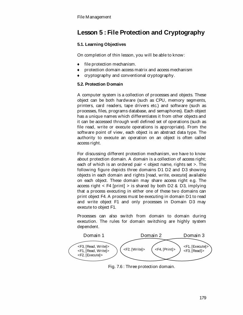
File Management
179
Lesson 5 : File Protection and Cryptography 5.1. Learning Objectives On completion of thin lesson, you will be able to know:
file protection mechanism. protection domain access matrix and access mechanism cryptography and conventional cryptography.
5.2. Protection Domain A computer system is a collection of processes and objects. These object can be both hardware (such as CPU, memory segments, printers, card readers, tape drivers etc.) and software (such as processes, files, programs database, and semaphores). Each object has a unique names which differentiates it from other objects and it can be accessed through well defined set of operations (such as file read, write or execute operations is appropriate). From the software point of view, each object is an abstract data type. The authority to execute an operation on an object is often called access right. For discussing different protection mechanism, we have to know about protection domain. A domain is a collection of access right; each of which is an ordered pair < object name, rights set >. The following figure depicts three domains D1 D2 and D3 showing objects in each domain and rights [read, write, execute] available on each object. These domain may share access right e.g. The access right < F4 [print] > is shared by both D2 & D3, implying that a process executing in either one of these two domains can print object F4. A process must be executing in domain D1 to read and write object F1 and only processes in Domain D3 may execute to object F1.
Processes can also switch from domain to domain during execution. The rules for domain switching are highly system dependent.
Fig. 7.6 : Three protection domain.
Domain 1 Domain 2 Domain 3
<F3, [Read, Write]> <F1, [Read, Write]> <F2, [Execute]>
<F2, [Write]> <F4, [Print]> <F1, [Execute]> <F3, [Read]>

Operating System
180
5.3. Access Matrix A problem related to protection is now the system keeps track of which objects belongs to which domain. To solve this problem, Access matrix is used. In this access matrix, the rows represents domain and the column represents objects. Each entry in the matrix consist of a set of access rights since objects are explicitly defined by column, we can omit object name from the access rights. The matrix for the previous Fig. 7.6 is as follows:
Object Domain F1 F2 F3 Printer
D1 Read write Execute Read write D2 write Print D3 Execute Read
Execute Print
Fig. 7.7 Access matrix.
Access matrices are inefficient for storage of access rights in a computer system because they tend to be large and sparse. The actual forms of representation of access rights, captured and expressed by the access matrix differ in practice in accordance with the access control mechanism in use. The common access control mechanisms are :
Access hierarchies such as levels of execution privilege and block structured programming languages.
Access lists of all subjects having access rights to a particular object
Capabilities, or tickets for objects; that specify all access rights of a particular subject.
5.4. Cryptography One way to strengthen security in computer systems is to encrypt sensitive records and messages in transit and in storage. The basic model of a cryptographic system is illustrated in Fig. 7.8. The original unenciphered text is called the plaintext or the clear text. It can be encrypted using some encryption method parametrized by a key. The result is called ciphertext. The ciphertext may be stored or transmitted via the communication medium, such as wires and radio links, or - more traditionally - by a messenger. Plaintext can be obtained by decrypting the
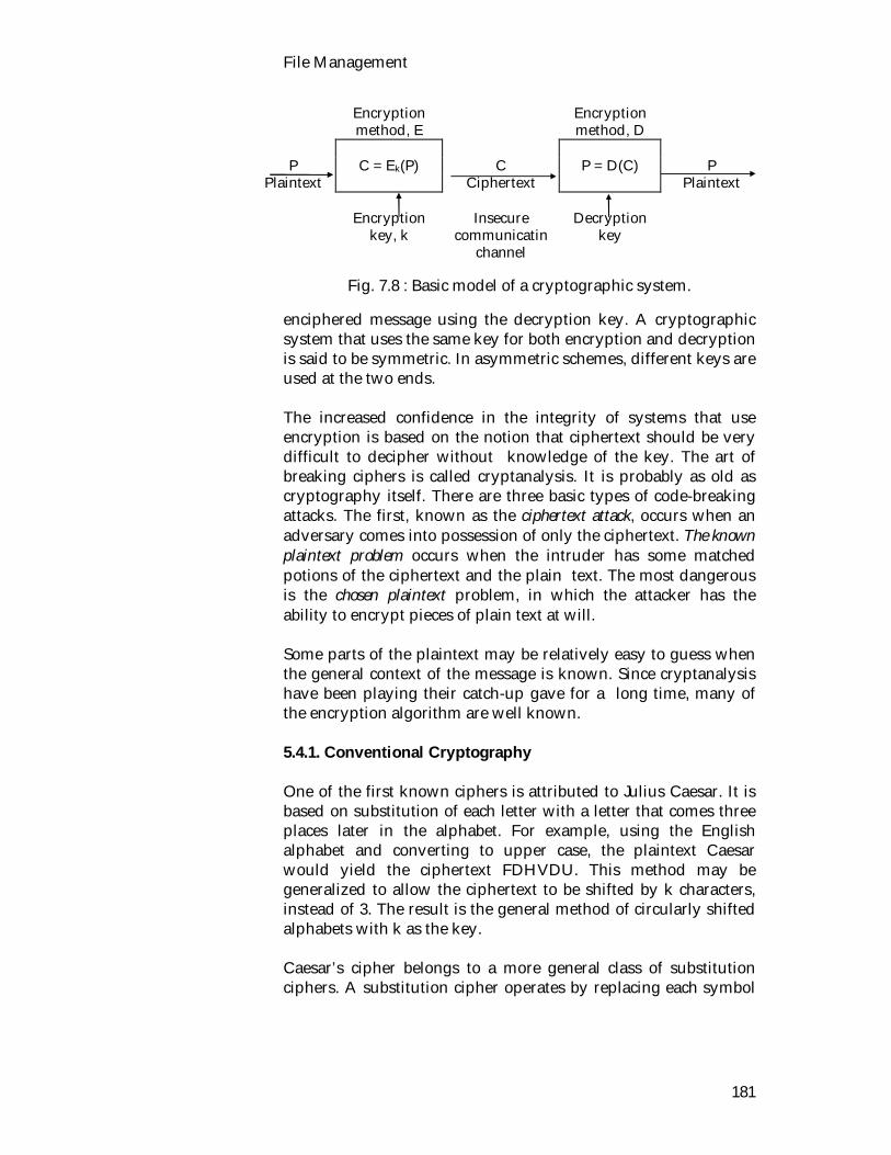
File Management
181
Encryption method, E
Encryption method, D
P C = Ek(P) C P = D(C) P
Plaintext Ciphertext Plaintext
Encryption key, k
Insecure
communicatin channel
Decryption
key
Fig. 7.8 : Basic model of a cryptographic system.
enciphered message using the decryption key. A cryptographic system that uses the same key for both encryption and decryption is said to be symmetric. In asymmetric schemes, different keys are used at the two ends. The increased confidence in the integrity of systems that use encryption is based on the notion that ciphertext should be very difficult to decipher without knowledge of the key. The art of breaking ciphers is called cryptanalysis. It is probably as old as cryptography itself. There are three basic types of code-breaking attacks. The first, known as the ciphertext attack, occurs when an adversary comes into possession of only the ciphertext. The known plaintext problem occurs when the intruder has some matched potions of the ciphertext and the plain text. The most dangerous is the chosen plaintext problem, in which the attacker has the ability to encrypt pieces of plain text at will. Some parts of the plaintext may be relatively easy to guess when the general context of the message is known. Since cryptanalysis have been playing their catch-up gave for a long time, many of the encryption algorithm are well known. 5.4.1. Conventional Cryptography One of the first known ciphers is attributed to Julius Caesar. It is based on substitution of each letter with a letter that comes three places later in the alphabet. For example, using the English alphabet and converting to upper case, the plaintext Caesar would yield the ciphertext FDHVDU. This method may be generalized to allow the ciphertext to be shifted by k characters, instead of 3. The result is the general method of circularly shifted alphabets with k as the key. Caesar’s cipher belongs to a more general class of substitution ciphers. A substitution cipher operates by replacing each symbol

Operating System
182
or a group of symbols in the plaintext by other symbols in order to disguise the originals. Fig. 7.9 illustrates a function based substitution using the exclusive OR (XOR) function on the numeric representations of plaintext and the key. For the purposes of this example, the numeric representation is obtained by a simple encoding that numbers letters of the English alphabet in sequence, starting with A = 01 and ending with Z = 26. The key is a three-letter combination, EFG, which is repeated as necessary. The first letter of the ciphertext is obtained as an XOR of the numeric equivalent of the first letter of the plaintext, 10 for, J, and of the key, 5 for E. The remainder of the ciphertext is produced by pairwise XORing letters of the plaintext and of the key. The message can be deciphered by applying XOR pairwise to letters of the ciphertext and of the key. JULIUSCAESAR Plaintext EFGEFGEFGEFG Key, EFG repeated 1 0 2 1 1 2 0 9 2 1 1 9 0 3 0 1 0 5 1 9 0 1 1 8 Plaintext, numeric 0 5 0 6 0 7 0 5 0 6 0 7 0 5 0 6 0 7 0 5 0 6 0 7 Key EFG, numeric 1 5 1 9 1 1 1 2 1 9 2 0 0 6 0 7 0 2 2 2 0 7 2 1 Ciphertext (plain XOR key) OSKLSTFGBVGU Ciphertext, letter equivalent
Fig. 7.9 : A function-based substitution cipher.
A substitution cipher can be made unbreakable by using a long non-repeating key. Such a key is called a one-time pad. A one-time pad may be formed by using words from a book starting from a specific place known to both the sender and the receiver. For example, starting with this sentence and using XOR on ASCII encoding of the letters of the plaintext and of the key, the encryption would proceed as depicted in Fig. 7.10. The textual equivalent of the ciphertext is not given because it contains a number of non-printable ASCII characters. The message can be deciphered by reversing the process. XORing each letter of the ciphertext with the ASCII representation of the key produces the ASCII encoding of a letter of the plaintext. One-time pad ciphers are unbreakable because they give no information to the cryptanalyst. The primary difficulty with one-time pads is that the key must be as long as the message itself, so key distribution becomes a problem. Since a different pad must be
Difficulty of one time pad.

File Management
183
used for each communication, the two parties must maintain full synchrony in observing the prescribed sequence. The loss of sequence, which an adversary may induce by capturing messages, may result in failure to communicate. Transposition ciphers, operate by reordering the plaintext symbols. Whereas substitution ciphers preserve the order of the plaintext symbols but try to disguise them, transposition ciphers rearrange the symbols without otherwise altering them.
JULIUSCAESAR Plaintext FOREXAMPLEEST, key starting sentience (one time paid)
7 4 8 5 7 6 7 3 8 5 8 3 6 7 6 5 6 9 8 3 6 5 8 2 Plaintext, ASCII 7 0 7 9 8 2 6 9 8 8 6 5 7 7 8 0 7 6 6 9 8 3 8 4 Key EFG, A S C I I 1 2 2 6 3 0 1 2 1 3 1 8 1 4 1 7 0 9 2 2 1 8 0 6 Ciphertext=plain XOR Key
Fig. 7.10 : A one-time pad.
An example of a transposition cipher, called the columnar transposition, is illustrated in Fig. 7.10. The encryption key is a word or a phrase that contains no repeating letters - CONSULT in this example. Encryption is performed by writing the plaintext in columnar fashion, with each row length corresponding to the chosen key length, 7 in Fig. 7.11. The matrix must be full, so any leftover space in the last row is padded with some characters. The columns are numbered in some prearranged way, such as the relative ordering in the keyword letters in the alphabet. The ciphertext is obtained by reading the columns in some fashion, such as all letters from top to bottom in column 1 followed by the others in sequence. Since transition ciphers do not attempt to conceal plaintext symbols, their use may be detected by verifying that the ciphertext contains the expected frequency of letters of the alphabet. C O N S U L T Keyword 1 4 3 5 7 2 6 Column numbers E N C R Y P T Plaintext: I O N I S P E ENCRYPTIONISPERFORMEDBYWRITINGTHEPLAIN R F O R M E D B Y W R I T I N G T H E P L Ciphertext: A I N T E X T EIRBNAPPETPXCNOWTNNOFYGIRIRRGTTEDILTY
Fig. 7.11 : Transportation cipher.

Operating System
184
The next step, then, is to guess the length of the key, possibly aided by looking for a likely word or a phrase. If the plaintext is in a natural language, a cryptanalyst can mount a statistical attack.
5.5. Exercise 5.5.1. Multiple choice questions 1. Asymmetric schemes i) use the same keys ii) different keys iii) cipher text iv) none of the above. 2. One time pad ciphers are i) breakable ii) unbreakable iii) transposable iv) none of the above. 5.5.2. Questions for short answers a) What do you know about protection? b) Distinguish between protection and security. c) What is protection domain? d) Define objects, protection domain and access rights. e) Discuss protection domain and access matrix. f) Define ciphertext, plantext, one-time pad ciphers. 5.5.3. Analytical questions a) What is the cipher text? b) Describe Different types of substitution ciphers.
Unit 8 : DOS Lesson 1 : Structure and Process in
MS-DOS 1.1. Learning Objectives On completion of this lesson you will be able to know : BIOS, kernel and shell the booting system of MS-DOS computer operation of TSR programs processes in MS-DOS. 1.2. Structure of MS-DOS MS-DOS is structured in three layers, as follows :
The BIOS (Basic Input Output System). The kernel. The shell, command .com.
The BIOS is a collection of low-level device drivers that serve to isolate MS-DOS from the details of the hardware. For example, the BIOS contains calls to read and write from absolute disk addresses, and to read a character from the keyboard and write a character to the screen. The BIOS is usually supplied by the computer manufacturer, rather than by Microsoft, and is generally located, in a ROM in the 64k block just under the 1M address space limit. BIOS procedures are called by trapping to them via interrupt vectors, rather than via direct procedure calls. This makes it possible for the vendor to change the size and location of BIOS procedures in new models, without having to relink the operating system. The file io.sys (called ibmbio.com) is a hidden file present on all MS-DOS systems. It is loaded immediately after the computer is booted, and provides a procedure call interface to the BIOS, so the kernel can access BIOS services by making procedure call to io.sys instead of traps to the ROM. In addition, this file holds those BIOS procedures not in the ROM. The existence of io.sys further isolates the kernel from hardware details.
BIOS

Operating System
186
The kernel is contained in another hidden file, msdos.sys (which IMB calls ibmdos.com) and contains the machine-independent part of the operating system. It handles process management, memory management, and the file system, as well as the interpretation of all system calls. The third part of what most people think of as the operating system is the shell, command.com. Of course, this program is not part of the operating system, and can be replaced by the user. The standard command.com consists of two pieces, a resident portion, that is always in memory, and a transient portion, that is only in memory when the shell is active. The transient portion is located at the high end of memory, and can be overwritten by user programs that need the space. When control passes back to command.com, it checks to see if the transient portion is still intact, and if not, reloads it. MS-DOS computers are booted as follows. When the power is turned on, control is transferred to address 0xFFFF0 by hardware. This location is always in a ROM, and contains a jump to the bootstrap procedure in the BIOS ROM. The bootstrap procedure carries out some hardware tests, and if the machine passes, it tries to read in the boot sector from diskette A:. If no diskette is present in drive A:, the primary boot sector of the hard disk is read in. The partition table in the primary boot sector tells where the partitions are and which one is active. The active partition is then selected and its first sector, the secondary boot sector, is read in and executed. This two-step boot procedure is only used for hard disks. Its function is to allow automatic booting of both MS-DOS and other operating systems. The boot sector reads its own root directory to see if io.sys and msdos.sys (or ibmbio.com and ibmods.com) are present. If so, it reads them both into memory and transfers control to io.sys. Once loaded, io.sys calls BIOS procedures to initialize the hardware. Then sysinit takes over and reads config.sys to cnfigure the system. This job includes allocating the buffer cache, loading device drivers, and setting up code pages for the national language to be used. Finally sysinit uses MS-DOS itself to load and execute command.com. In this respect, sysinit does the work init does in UNIX. After initializing itself, command.com reads and executes autoexec.bat, which is an ordinary shell script to doing whatever initialization the user wants.
Command.com.
Kernel
How to boot MS-DOS computer.

DOS
187
1.3. Processes in MS-DOS When the system is booted, one process, command.com (the keyboard-oriented shell) starts up and waits for input. When a line is typed, command.com starts up a new process and passes control to it, waiting until it is finished. MS-DOS has two kinds of executable binary files, which result in two slightly different kinds of processes. A file with extension .com, as in prog.com, is a simple executable file. It has no header and only 1 segment. The executable file is an exact, byte-for-byte image of the executable code. The file is loaded into memory exactly as is and run. This model of a process comes directly from, CP/M. A process started from a .com file has one text + data + stack segment, of up to almost 64k. Even though the process cannot exceed 64k, it is nevertheless allocated all of available memory. The stack is at the top of the common 64k segment. The other kind of executable file is the .exe file. A process created from one of these files can have a text segment, a data segment, a stack segment, and as many extra segments as it wants. Unlike .com files .exe files contain relocation information, so they can be relocated on-the-fly as they are being loaded. The operating system tells the difference between .com files and exe. files by looking at the first two bytes, not by looking at the file name extension. The first 256 bytes of every MS-DOS process is a special data block called the PSP (Program Segment Prefix). The concept comes directs from CP/M. The PSP is constructed by the operating system at the time the process is created. For .com files, it counts as part of the process' address space, and can be addressed using addresses 0 to 255. For this reason, all .com processes begin at address 256, not at address 0. In contrast, .exe files are relocated above the PSP, so their address 0 is the first byte above the PSP. This maneuver avoids wasting 256 bytes of address space. The PSP contains the program's size, a pointer to the environment block, the address of the CTRL-C handler, the command string, a pointer to the parent's PSP, the file descriptor table, and other information.
.com file
.Exe file
PSP
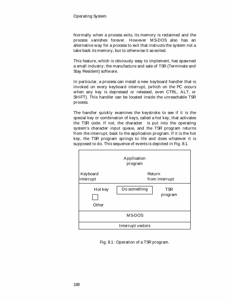
Operating System
188
Normally when a process exits, its memory is reclaimed and the process vanishes forever. However MS-DOS also has an alternative way for a process to exit that instructs the system not a take back its memory, but to otherwise it as exited. This feature, which is obviously easy to implement, has spawned a small industry; the manufacture and sale of TSR (Terminate and Stay Resident) software. In particular, a process can install a new keyboard handler that is invoked on every keyboard interrupt, (which on the PC occurs when any key is depressed or released, even CTRL, ALT, or SHIFT). This handler can be located inside the unreachable TSR process. The handler quickly examines the keystroke to see if it is the special key or combination of keys, called a hot key, that activates the TSR code. If not, the character is put into the operating system's character input queue, and the TSR program returns from the interrupt, back to the application program. If it is the hot key, the TSR program springs to life and does whatever it is supposed to do. This sequence of events is depicted in Fig. 8.1.
Fig. 8.1 : Operation of a TSR program.
Application
program
Keyboard Return interrupt from interrupt Hot key TSR program Other
MS-DOS
Interrupt vectors
Do something

DOS
189
It is also possible to have an interrupt handler that searches for multiple hot keys, and dispatches to the appropriate procedure. For example, one could have a TSR program that pops up a calendar for ALT-F1, a calculator for ALT-F2, a memo pad for ALT-F3, a clock for ALT-F4, a phonebook for ALT-F5, a cardfile for ALT-F6 and also so on. Writing a TSR program is not so easy. Several problems must be solved. The TSR program cannot use MS-DOS to read the keyboard for subsequent input and cannot use it to write on the screen. It certainly cannot use it to access files. It cannot even use the BIOS. So, writing a TSR program is not so easy for the beginners, because a large number of TSR programs are available on the market. DOS key is an example of TSR program. 1.3.1. Implementation of Processes in MS-DOS Process management is not complex in MS-DOS because there is no multiprogramming. When a process invokes the LOAD_AND_EXEC system call, MS-DOS carries it out in the following steps :
Find a block of memory large enough to hold the child
process. For an .exe file, the size can be deduced from information in the header. For a .com file, all of available memory is allocated, but the program can return unused memory if it so desires.
Build the PSP in the first 256 bytes of the allocated
memory. Load the executable binary file into the allocated memory
starting at the first byte above the PSP. For .exe files, a relocation constant must be added to all relocatable addresses. For .com files, nothing is changed.
Start the program. The starting address of an .exe file is
contained in the header. The starting address of a .com file is address 0x 100 (to skip over the PSP).

Operating System
190
The PSPs play an important role in MS-DOS. A global variable inside the system points to the current process' PSP. The PSP contains all the state information needed. 1.4. Exercise 1.4.1. Multiple choice questions 1. TSR stands for i) Terminal state Routine ii) Terminal security Resident iii) Terminate and stay Resident iv) Terminate and stays Routine. 2. Hot key activates the i) program code ii) TSR code iii) object code iv) source code. 3. MS-DOS has i) two kinds of executable binary file ii) three layers kinds of executable binary file iii) Four layers kinds of executable binary file iv) None of the above. 1.4.2. Questions for short answers a) What do you understand by BIOS? What are functions of
BIOS? b) What is kernel? List the work of kernel. c) How MS-DOS computers are booted? d) What is the difference between .com file and .exe file? e) What do you mean by PSP? What are information that
must be contained in PSP? f) What do you understand by TSR? Describe the operation
of TSR program. g) Why do must MS-DOS machines have the BIOS in ROM?
DOS
191
1.4.3. Analytical question a) Describe different layers of MS-DOS. Lesson 2 : Memory Management in DOS 2.1. Learning Objectives On completion of this lesson you will be able to know :
memory model of DOS different memory management techniques different types of memory. 2.2. Memory Model of DOS Memory (RAM) provides temporary storage for programs and data. It resides on the main system board of your computer or add on memory boards. Programs need to run. Some require more memory than others. How much memory is available affects which programs you can run, how fast they run, and how much data a program can work with at one time. It is important to know how much and what type of memory your computer has. In the following discussion, we will look different kinds of memory. 2.2.1. Conventional Memory The memory between 0 and 640K was reserved for operating system, device drivers and ordinary programs. This region i.e. up to first 640k of memory on computer is called conventional memory. MS-DOS manages conventional memory, you don't need an additional memory manager to use conventional memory. ALL MS-DOS based programs require conventional memory. 2.2.2. Upper Memory Area (UMA) The remaining 384K of memory i.e. from 640K to 1M, is called UMA (upper memory are). The upper memory area is used by system hardware, such as your display adapter. UMA is reserved for video RAMs. Basic ROMs and other I/O related functions. Unused parts of the upper memory area are called upper memory blocks (UMBs). On an 80386 or 80486 computer, UMBs can be used for running device drivers and memory-resident programs.
Memory
Upper memory

Operating System
192
2.2.3. Extended Memory (XMS) Memory beyond 1 megabyte (MB) on computer with 80286, 80386, or 80486 processors is called extended memory. Extended memory requires an extended-memory manager, such as HIMEM. Windows and Windows-based applications require extended memory. Extended memory is used for RAM disks and buffer cache. 2.2.4. High Memory Area (HMA) The first 64KB of extended memory is called high memory area. On a computer with extended memory, Setup installs MS-DOS to run in the high memory area. This leaves more conventional memory available for programs. 2.2.5. Expended Memory (EMS) Memory in addition to conventional memory that some MS-DOS-based applications can use. Most personal computers can accommodate expanded memory. Expanded memory is installed on an expanded-memory board and comes with an expanded-memory manager. Programs use expanded memory 64k at a time by addressing a part of the upper memory areas called an EMS page frame. Because an expanded-memory manager gives access to a limited amount of expanded memory at a time, using expanded memory is slower than using extended memory. EMM386 can simulate expanded memory for program that require it. Although Windows and Windows-based applications do not use expanded memory, Windows can also simulate expanded memory for MS-DOS-based applications that need it. For example : LIM EMS expanded memory developed by three companies Lotus, Intel and Microsoft. The following illustration shows the memory configuration of a typical computer. 3. MB 1.MB
High memory area
Extebded memory
(XMS) (2MB)
HMA
Upper memory
area (384k)
Conventional memory 6430K
Expanded memory
(EMS) (1,MB)

DOS
193
640K
Fig. 8.2 : Different types of memory. The MS-DOS memory model is very complicated. Six memory management techniques are used to break the 640K barrier and make some use of extended memory. These areas follows :
Table-8.1: Memory management techniques in MS-DOS.
Technique Use HMA Move MS-DOS out of the bottom 640k Upper memory Get MS-DOS, drivers, and TSR programs
out of the way Expanded memory Allow large data sets to be used by
mapping them in and out RAM disk Utilize extended memory by simulating a
disk in memory Caching Utilize extended memory by putting a
buffer cache there 2.3. Memory Management in MS-DOS Memory is divided up into contiguous blocks called arenas, each arena starting on a paragraph boundary and containing a whole number of paragraphs, as depicted. Each arena starts with a 16-byte arena header. The header begins with a number. Then comes a pointer to the PSP of the process that allocated the arena, or 0 if it is free. Next is the arena's size in paragraphs. Finally is a filed that can hold the name of the executable binary file that owns the arena. Actually the arenas do not form a linked because the headers contain sizes rather than pointers. When MS-DOS has to allocate memory. It searches the arena chain starting at the low end until it finds a block that is large enough. If the arena chosen is too large, a piece is broken off for use, and a new arena is created to represent the hole over. When memory is
Memory management

Operating System
194
freed, adjacent free arenas are not merged because the arena chain is not a doubly linked list. Merging occurs the next time the chain is searched starting at the beginning. As a consequence of this memory management method, a program with dynamic tables for which it is constantly allocating and freeing memory is likely to own chunks of memory spread all over the 1M address space. Although the arena scheme works for upper memory, it does not work with extended memory because the sizes in the arena headers are only 16 bits. To use memory above the 1M mark, it is necessary to install memory manager. A memory manager is a device driver that provides access to a particular type of memory. You do not need a memory manager to use conventional memory, because MS-DOS has a built-in conventional-memory manager. MS-DOS includes the following memory managers
HIMEM, which provides access to extended memory. MS-DOS Setup install HIMEM automatically if you have an 80286, 80386, or 80486 computer with extended memory.
EMM386, which provides access to the upper memory area. EMM386 can also use extended memory to simulate expanded memory.
MS-DOS does not include an expanded-memory manager for physical expanded memory, since each expanded-memory board requires its own memory manager. To use physical expanded memory, you must install the memory manager that came with your expanded-memory board. MS-DOS also includes the SMARTDRIVE .SYS and RAMDRIVE .SYS programs. These are not memory manager, they are optimization programs that use some memory to speed up your system. SMARDRIVE used extended memory for caching and RAMDRIVE use extended memory as a RAM DISK.

DOS
195
2.4. Exercise 2.4.1. Multiple choice questions 1. You do not need a memory manager to use i) conventional memory ii) upper memory iii) extended memory iv) high memory. 2. UMBs stands for i) upper memory area ii) upper memory blocks iii) upper memory bytes iv) undelivered message block. 2.4.2. Questions for short answers a) What is a memory manager? b) Why are memory managers not needed for conventional
memory? c) List the memory managers which exist in MS-DOS. d) What are the functions of SMARTDRIVE.SYS and
RAMDRIVE.SYS? e) What do you understand by arena? f) Why do arenas always begin on a paragraph boundary
and have a size that is an integral number of paragraphs? g) List the use of different types of memory management
techniques. h) What do you understand by EMS? Give example of an
EMS. 2.4.3. Analytical question a) Describe different kinds of memory of computer.

Operating System
196
Lesson 3 : MS-DOS File System 3.1. Learning Objectives On completion of this lesson you will be able to : distinguish between the MS-DOS and UNIX file systems list some points of comparison between MS-DOS and UNIX
file systems know the file attributes of MS-DOS define the term FAT, partition table. 3.2. The Difference Between UNIX File System and DOS File System
UNIX file system DOS file system 1. UNIX file names are either
14 characters or 255 characters depending on the version.
1. MS-DOS file names have a basic part of 8 characters, optionally followed by an extension. The extension always starts with a dot and contains 1 to 3 characters. For example
.bat - batch file.
.com - CP/M-style single segment executable binary file .doc - Documentation file .exe - Modern multisegement executable binary file with header .obj - Object file produced by a compiler .sys - Device driver or other system file .txt - ASCII text file.
The Difference Between UNIX File System and DOS File System.
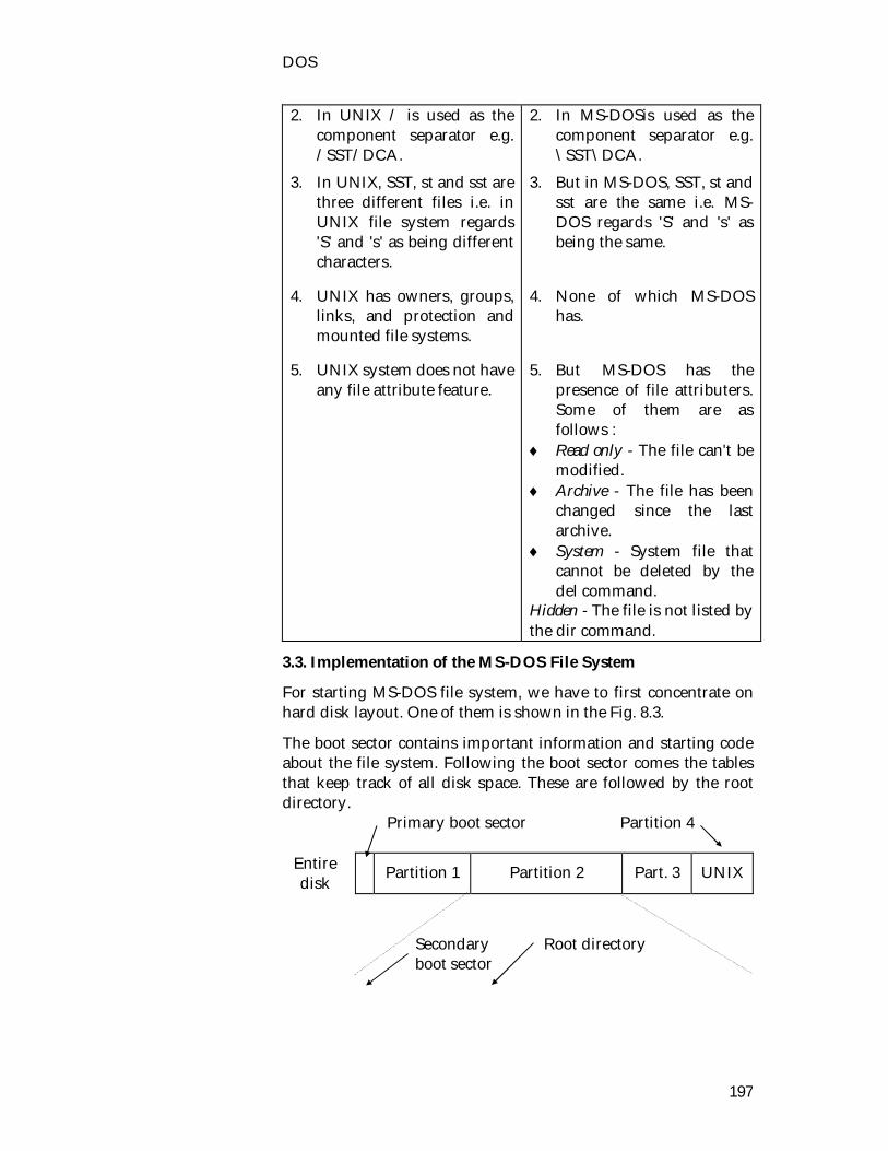
DOS
197
2. In UNIX / is used as the component separator e.g. /SST/DCA.
3. In UNIX, SST, st and sst are three different files i.e. in UNIX file system regards 'S' and 's' as being different characters.
4. UNIX has owners, groups,
links, and protection and mounted file systems.
5. UNIX system does not have
any file attribute feature.
2. In MS-DOSis used as the component separator e.g. \SST\DCA.
3. But in MS-DOS, SST, st and sst are the same i.e. MS-DOS regards 'S' and 's' as being the same.
4. None of which MS-DOS
has. 5. But MS-DOS has the
presence of file attributers. Some of them are as follows :
Read only - The file can't be modified.
Archive - The file has been changed since the last archive.
System - System file that cannot be deleted by the del command.
Hidden - The file is not listed by the dir command.
3.3. Implementation of the MS-DOS File System
For starting MS-DOS file system, we have to first concentrate on hard disk layout. One of them is shown in the Fig. 8.3.
The boot sector contains important information and starting code about the file system. Following the boot sector comes the tables that keep track of all disk space. These are followed by the root directory. Primary boot sector Partition 4
Entire disk
Partition 1
Partition 2
Part. 3
UNIX
Secondary Root directory boot sector

Operating System
198
One partition
FAT
Data blocks
File Optional allocation duplicate table FAT
Fig. 8.3 : The MS-DOS disk layout.
The boot sector contains the partition table at the end. This table contains entries for indicating the start and end of each partition, up to a maximum of four partitions. Each partition can contain a different file system. Following the boot sector comes the FAT (File allocation Table). Which keeps track of all disk space on the device. The FAT contains one entry for each block on the disk. The block size is given in the boot sector. The conceptual layout of the FAT is shown in Fig. 8.4.
There is a one-to-one correspondence between FAT entries and disk blocks, except for the first two FAT entries, which encode the disk class. In this example, we show three files, A, B, and C. File A begins at block 6. The FAT entry for 6 is 8, meaning that the second block of the file is block 8. The FAT entry for 8 is 4, meaning that the next block is 4. The FAT entry for 6 is 2. Finally, the entry for 2 is a special code indicating end of file. Thus given the number of the first block of a file, it is possible to locate all the blocks by following the chain through the FAT. The directory entry for each file contains the starting block, and the FAT provides the rest of the chain.
A directory in MS-DOS has a 32 byte entry for each file or directory it contains, as illustrated in Fig. 8.5. The first 11 characters hold the file name and extension.
FAT 0 X 1 X 2 EOF 3 13 4 2 5 9 6 8 7 FREE 8 4 9 12
File A : 6 8 4 2 File B : 5 9 12 File C : 10 3 13
Disk size
Not allocated

DOS
199
10 3 11 FREE 12 EOF 13 EOF 14 FREE 15 BAD
Fig. 8.4 : The MS-DOS file allocation table. Next comes the attribute byte, containing the following bits : A - Archive bit (set when file is modified, cleared when it is
backed up) D - Set to indicate that the entry is for a directory V - Set to indicate that the entry is for the volume label S - Set for system (i. e., undeletable files H - Set for hidden files (i. e., not listed by dir) R - Read-only bit (file may not be written) The attribute byte may be read and written using system calls. The time and date of last modifications are stored in the next two fields. The last two fields hold the number of the first block and the file size. Using the block number, the start, of the chain in the FAT can be located, thus making it possible to find all the blocks.
16 bits
File name (8)
Extension (3)
Reserved
for future use (10)
Time (2) Date (2)
First block (2)
File size (4)
End of file
This block is marked as a bad block
A D V S H R
Attribute byte : A: Archive D: Directory V: Volume label S: System file H: Hidden file R: Read-only
Operating System
200
Fig. 8.5 : An MS-DOS directory entry.
In the above Fig. 8.5 numbers in parentheses are the sizes in bytes. The shaded areas are not used. 3.4. Exercise 3.4.1. Multiple choice questions 1. FAT means i) File access table ii) File allocation table iii) File allocation text iv) None of the above. 2. A directory in MS-DOS has a i) 8-bite entry ii) 16-byte entry iii) 32-bit entry iv) 32-byte entry. 3. The FAT contains i) one entry for each block on the disk ii) multiple entry for each block on the disk iii) partition table for each block iv) directory entry for each block on the disk. 3.4.2. Questions for short answers a) What do you mean by Fat? What are the information that
must be kept in FAT? b) What are the differences between MS-DOS file system and
UNIX file system? c) Compare MS-DOS file system with UNIX file system. d) Describe the conceptual layout of FAT.

DOS
201
e) Describe MS-DOS directory entry. f) List the bits of the file attribute byte. 3.4.3. Analytical questions A FAT starts out with the following values :
y, y, 8, -1, -1-1, 3, 2, 5, 0, 0 where x is not relevant for our purposes -o indicates a free slot, -1 indicates end of file In the directory entry for a certain file as the starting block, how many block does that file contain? Lesson 4 : User Interface in Windows On completion of this lesson you will be able to : learn about user interface of windows work under windows operating system use different commands of windows. 4.1. Windows Microsoft Windows is not technically an operating system - it is an extension module that sits above DOS. It provides a graphical user interface (GUI) and as much multitasking as can be accomplished with DOS still present. Because of its GUI, Windows has a different API than DOS, and Windows applications will not run under DOS without Windows. The reverse situation, however, has been provided for in the design of Windows, and most DOS however, has been provided for in the design of Windows, and most DOS programs will run under Windows. Version 3.1 of Windows includes some built-in multimedia capabilities, such as the MCI API. It handles audio very well. Windows is a 16-bit system, the same as DOS, although Microsoft is in the process of providing 32-bit extensions, which will be able to benefit form 32-bit hardware. It will require special programming in applications to take full advantage of the 32-bit features. 4.2. Windows NT

Operating System
202
NT means New Technology. Like OS/2, Windows NT is a complete operating system - it does not require DOS. Therefore, all the limitations of DOS are gone. Many other features are built in to make it a strong competitor to OS/2 : true multitasking, network features, true 32-bits, running DOS-Windows programs, etc. Windows NT is even more demanding of system resources (memory and storage) than OS/2, requiring more than 8 megabytes for minimum running and taking upwards of 5 megabytes of storage just for the system and its features. However, those kinds of hardware needs are being met at lower and lower cost. 4.3. Windows 95 Screen Various items appear on desktop when start Windows. Here are four important ones.
My Computer Double-click this icon to see computer’s contents and manage files. Network Neighborhood Double-click this icon to see available resources on the network, if computer is or can be connected to one. Recycle Bin

DOS
203
The Recycle Bin is a temporary storage place for deleted files. One can use it to retrieve files deleted in error. Start Button Click the Start button on the taskbar to start a program, open a document, change system settings, get Help, find items on your computer, and more. There are some familiar elements of Microsoft Windows version 3.1 that have changed for Windows 95. They are as follows : Program Manager Old program groups will be found by clicking the Start button and then pointing to Programs. Groups appear as folders on the Programs menu.
File Manager To manage the files, the click the Start button, point to Programs, and then click Windows Explorer. Directories appear as folders.

Operating System
204
MS-DOS Prompt To open an MS-DOS window, click the Start button, point to Programs, and then click MS-DOS Prompt.
Control Panel To open Control Panel, click the Start button, point to Setting, and then click Control Panel.

DOS
205
Print Manager To set up a printer or look at information about documents that will be printed, click the Start button, point to Settings, and then click Printers.
Run Command To use the Run command, click the Start button, and then click Run. One can run, MS-DOS-based and Windows-based programs, open folders, and connect to network resources by using Run.
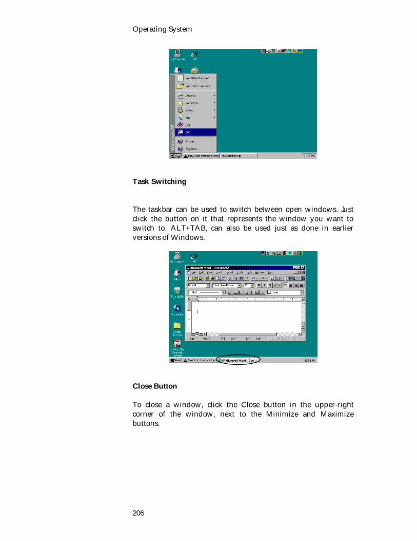
Operating System
206
Task Switching The taskbar can be used to switch between open windows. Just click the button on it that represents the window you want to switch to. ALT+TAB, can also be used just as done in earlier versions of Windows.
Close Button To close a window, click the Close button in the upper-right corner of the window, next to the Minimize and Maximize buttons.
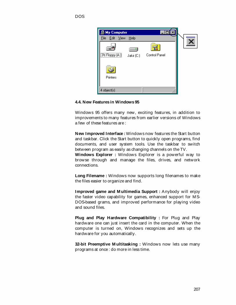
DOS
207
4.4. New Features in Windows 95 Windows 95 offers many new, exciting features, in addition to improvements to many features from earlier versions of Windows a few of these features are : New Improved Interface : Windows now features the Start button and taskbar. Click the Start button to quickly open programs, find documents, and user system tools. Use the taskbar to switch between program as easily as changing channels on the TV. Windows Explorer : Windows Explorer is a powerful way to browse through and manage the files, drives, and network connections. Long Filename : Windows now supports long filenames to make the files easier to organize and find. Improved game and Multimedia Support : Anybody will enjoy the faster video capability for games, enhanced support for MS-DOS-based grams, and improved performance for playing video and sound files. Plug and Play Hardware Compatibility : For Plug and Play hardware one can just insert the card in the computer. When the computer is turned on, Windows recognizes and sets up the hardware for you automatically. 32-bit Preemptive Multitasking : Windows now lets use many programs at once : do more in less time.

Operating System
208
Microsoft Exchange : Use Microsoft Exchange to view and work with all types of electronic communications, including e-mail and fixes. The Microsoft Network : This is new, affordable, and easy-to-use online service to communicate with people worldwide, using e-mail, bulletin boards, and the Internet. 4.5. Getting Started with Windows 95 A quick overview of getting started with Windows is shone below: Logging on to Windows When you start Windows, you may be prompted to log on to Windows or, if you are on a network, to log on to your network. If you don’t want to log on with a password, don’t type anything in the password box, and click OK. You won’t see this prompt in the future. To log on to Windows 1. In the User Name box, type your name. 2. In the Password box, type a password. The first time.
Windows prompts you to confirm your password.
The Start Button and Taskbar The Start button and taskbar are located at the bottom of the screen when Windows starts for the first time. By default, they are always visible when Windows is running.
Start button Taskbar Clock

DOS
209
Start with the Start menu When you click the Start button, a menu will be seen that contains everything one need to begin using Windows.
If you want to start a program, point Programs. If you want Help on doing something in Windows, click Help. The commands on the Start menu are described in more detail in the rest of this chapter. An overview of each command is shown below. This command Does this Programs Displays a list of programs you can start.
Documents Displays a list of documents that you’ve opened
previously.
Setting Displays a list of system components for which you can change setting.
Find Enables you to find a folder, file, shared computer, or mail message.
Help Starts Help. You can then use the Help Contents, Index, or other tabs to find out how to do a task in Windows.
Run Starts a program or opens a folder when you type an MS-DOS command.
Shut Down Shuts down or restarts your computer, or logs

Operating System
210
you off. Depending on your computer and the options you have chosen, you may see additional items on your menu. The Taskbar Every time you start a program or open a window, a button representing that window appears on the taskbar. To switch between windows, just click the button for the window you want. When you close a window, its button disappears from the taskbar. Depending on what task you’re working on, other indicators can appear in the notification area on the taskbar, such as a printer representing your print job or a battery representing power on your portable computer. At one end on the taskbar is the clock. To view or change settings, just double-click the clock or any of the indicators. 4.6. Starting and Quitting a Program Use the Start button to start any program you want to use, such as your word processor or a favorite game. To start a program 1. Click the Start button, and then point to Programs.
2. Point to the folder, such as Accessories, that contains the
program, and then click the program.
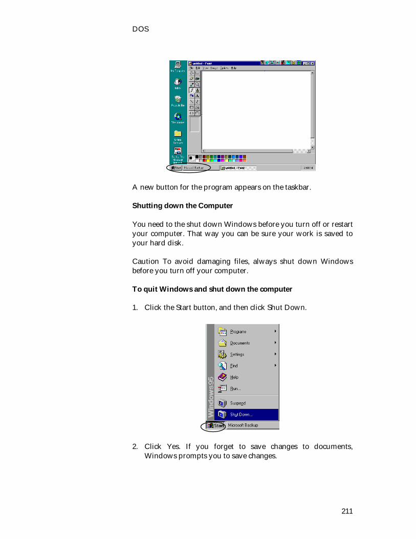
DOS
211
A new button for the program appears on the taskbar. Shutting down the Computer You need to the shut down Windows before you turn off or restart your computer. That way you can be sure your work is saved to your hard disk. Caution To avoid damaging files, always shut down Windows before you turn off your computer. To quit Windows and shut down the computer 1. Click the Start button, and then click Shut Down.
2. Click Yes. If you forget to save changes to documents,
Windows prompts you to save changes.

Operating System
212
3. A screen message lets you know when you can safely turn off
the computer. For information about the other options in this dialog box, click the Help button. 4.7. Seeing what’s on the Computer In Windows 95, the things you have on your computer - your programs, documents, and data files, for example - are all accessible from one place called My Computer. When you first start Windows, My Computer is located at the upper left of your Windows screen, or desktop. To see what’s on the computer Double-click My Computer. A window appears, displaying several different pictures, called icons.
To use an item in My Computer, double-click the icon. The following list describes what happens when you double-click the various icons. Double-click this icon
To see the

DOS
213
The contents of a flopping disk in the computer’s 3.5-inch drive, if there is one.
The contents of the computer’s hard disk.
Jakir (D:)
The contents of a compact disc in the computer’s CD-ROM drive, if there is one.
Change the setting for the computer.
Set up printers and view information about the printers and the documents you print.
When you double-click a disk-drive icon in My Computer, a window such as the following appears.
This icon Represents
A folder, which can contain files and other folders. To keep things organized, your work is stored in folders, just as you might store it in your office or at home. Your directories appear as folders.
A file, the basic unit of storage in Windows. The documents you use and create are files, and so are the programs you use. Different types of files may have different-looking icons. This standard (generic) icon is used when a file type does not have a specific icon associated with it.

Operating System
214
A document that was created with WordPad, a text editor that is included with Windows.
You double-click these icons to see the contents of the folder or the information in the file, or to start a program. Hands on Practices 1. i) Open MS-DOS prompt. ii) Select Control Panel iii) Set up Printer iv) Run MS-DOS and Windows based programs. 2. i) Use Close button ii) Find folder or file iii) Start a program iv) Shut down the computer.

Unit 9 : UNIX Lesson 1 : Features of UNIX 1.1. Learning Objectives On completion of this lesson, you will be able to : know the history of UNIX describe design principle explain some of the features of UNIX. 1.2. The History of UNIX Operating System The UNIX operating system was developed at AT&T Bell Laboratories in Murray Hill, New Jersey - one of the largest research facilities in the world. Since the original design and implementation of the UNIX system by Ken Thompson in 1969, it has gone through a maturing process. When the UNIX operating system was developed, many computers still ran single jobs in a batch mode. Programmers fed these computers input in the form of punch cards (these were also called IBM cards) and did not see the program again until the printer produced the output. Because these systems served only one user at a time, they did not take full advantage of the power and speed of the computers. Further, this working environment isolated programmer form each other. It made it difficult to share data and programs and it did not promote cooperation among people working on the same project. The UNIX time-sharing system provided three major improvements over single-user, batch systems. It allowed more than one person to use the computer at a time (the UNIX operating system is a multi-user operating system), it allowed a person to communicate directly with the computer via a terminal (it is interactive), and made it easy for people to share data and programs. The UNIX system was not the first interactive, multi-user operating system. An operating system named Multics was in use briefly at Bell Labs before the UNIX operating system was created. The Cambridge Multiple Access System had been developed in Europe, and the Compatible Time-sharing System (CTSS) had also been used for several years. The designers of the UNIX operating system took advantage of the work that had
The UNIX time-sharing system provided three major improvements over single-user, batch systems.
The UNIX operating system is a multi-user operating system.
It allowed a person to communicate directly with the computer via a terminal (it is interactive).
It easy for people to share data and programs.
Operating System
216
gone into these and other operating systems by incorporating the most desirable aspects of each of them. The UNIX system was developed by researchers who needed a set of modern computing tools to help them with their projects. The system allowed a group of people working together on a project to share selected data and programs while keeping other information private. The UNIX operating system became widely available in 1975. Bell Labs offered it to educational institutions at minimal cost. The schools, in turn, used it in their computer science programs, ensuring that computer science students became familiar with it. In addition to introducing its students to the UNIX operating system, the Computer Systems Research Group at the University of California at Berkeley made significant additions and changes to it. 1.3. Design Principles UNIX was designed to be a time-sharing system. The standard user interface (the shell) is simple and may be replaced by another, if desired. The file system is a multi-level tree, which allows users to create their own sub-directories. All user data files are simply a sequence of bytes. Disk files and I/O devices are treated as similarly as possible. Thus device dependencies and peculiarities are kept in the kernel as much as possible, and even in the kernel most of them are confined to the device drivers. UNIX supports multiple processes. A process can easily create new processes . UNIX is an excellent example of an operating system for a personal computer. It was originated first by one programmer, Ken Thompson, and then another, Dennis Ritchie, as a system for their own convenience. As such, it is small enough to understand. Most of the algorithms were selected for simplicity not speed or sophistication. Its clean design has resulted in many imitations and modifications.
UNIX was designed to be a time-sharing system.
UNIX supports multiple processes.

UNIX
217
UNIX was designed by programmers for programmers. Thus it has always been interactive, and facilities for program development have always been a high priority. The operating system is mostly written in C, a systems programming language. C was developed to support UNIX since neither Thompson nor Ritchie enjoyed programming in assembly language. The avoidance of assembly language was also necessary because of the uncertainty about the machine or machines on which UNIX would be run. It has greatly simplified the problems of moving UNIX from one hardware system to another. 1.4. Features of the UNIX System The UNIX operating system has many unique features. Like other operating systems, the UNIX system is a control program for computers. But it is also a well-thought-out family of utility programs and a set of tools that allows users to connect and use these utilities to build systems and applications. This section discusses both the common and unique features of the UNIX operating system. 1.4.1. Utilities The UNIX system includes a family of several hundred utility programs, often referred to as commands. These utilities perform functions that are universally required by users. An example is sort. The sort utility puts lists (or groups of lists) in order. The UNIX System Can Support Many Users Depending on the machine being used, a UNIX system can support from one to over one hundred users, each concurrently running a different set of programs. The cost of a computer that can be used by many people at the same time is less per user than that of a computer that can be used by only a single person at a time. 1.4.2. The UNIX System Can Support Many Tasks The UNIX operating system allows each user to run more than one job at a time. You can run several jobs in the background while giving all your attention to the job being displayed on your
UNIX system can support from one to over one hundred users.

Operating System
218
terminal and you can even switch back and forth between jobs. This multitasking capability enables users to be more productive. 1.4.3. The UNIX System Kernel The kernel is the heart of the UNIX operating system responsible for controlling the computer's resource and scheduling user jobs so that each one gets its fair share of the resources (including the CPU as well as access to peripheral devices such as disk storage, printers, and tape drives). Programs interact with the kernel through special functions called system calls. A programmer can use a single system call to interact with many different kinds of devices. 1.4.4. File Structure The UNIX file system provides a structure where files are arranged under directories and directories in turn are arranged under other directories and so forth in a treelike organization. This structure assists users in keeping track of large numbers of files by enabling them to group related files into directories. Each user has one primary directory and as many sub-directories as required. 1.4.5. Security : Private and Shared Files Like most multi-user operating systems the UNIX system allows users to protect their data from access by other users. The UNIX system also allows users to share selected data and programs with certain other users by means of a simple but effective protection scheme. 1.4.6. The Shell The shell is a command interpreter that acts as an interface between users and the operating system. When you enter a command at a terminal the shell interprets the command and calls the program you want. There are three popular shells in use today the Bourne Shell, the C Shell and the Corn Shell. The choice of shells demonstrates one of the powers of the UNIX operating system the ability to provide a customized user interface. The shell can be used as a high level programming language. Shell commands can be arranged in a file for later execution as a high level program.
The kernel is the heart of the UNIX.
The shell is a command interpreter.

UNIX
219
1.4.7. Device-Independent Input and Output Devices (such as a printer or terminal) and disk files all appear as files to UNIX programs. When you give the UNIX operating system a command you can instruct it to send the output to any one of several devices or files. This diversion is called output redirection. In a similar manner, a program's input that normally comes from a terminal can be redirected so that it comes from a disk file instead. 1.4.8. Inter-process Communication The UNIX system allows users to establish both pipes and filters on the command line. A pipe sends the output of one program to another program as input. A filter is a program designed to process a stream of input data and yield a stream of output data. Filters are often used between two pipes. A filter processes another program's output, altering it in some manner. 1.4.9. Job Control Job control allows users to work on several jobs at once switching back and forth between them as desired. Frequently when you start a job it is in the foreground, so it is connected to your terminal. Using job control you can move the job you are working with into the background so that you can work on or observe another job while the first is running. 1.4.10. Advanced Electronic Mail The Mail utility allows users to reply to a message, automatically addressing
the reply to the person who sent the message. allows users to use an editor (such as vi or emacs) to edit a
piece of electronic mail while they are composing it. presents users with a summary of all messages waiting for
them when they call it up to read their mail. can automatically keep a copy of all electronic mail users
send. allows users to create aliases that make it easier to send mail
to groups of people. allows users to customize features to suit their needs.
Operating System
220
1.4.11. Networking Utilities UNIX integrated support for networking including many valuable utilities that enable users to access remote systems over a variety or networks. 1.4.12. Graphical User Interfaces SunOS was one of the first UNIX systems to support computer graphics, on a bit mapped display, including a window system and graphical user interface. Sun's Network File System allows users to work with files that are actually stored on remote computers without any special tools, just as if the files were really stored on a user's local computer system. The X Windows System, developed in part by researchers at the Massachusetts Institute of Technology, available with most versionsGiven a terminal or workstation screen that supports X Windows a user can interact with the computer through multiple windows on the screen display graphical information or use special purpose applications to draw pictures or preview typesetter output. Other new features that are available from certain manufactures include concurrency, fault tolerance, and parallel processing. As the system continues to evolve, future versions will undoubtedly provide these and other new features meeting a wider variety of user's needs.
X Windows System provides the graphical user interface of UNIX today.
UNIX
221
1.5. Exercises 1.5.1. Multiple choice questions a. The UNIX operating system was first developed at i) Berkeley ii) AT & T Bell laboratories iii) Sun Microsystems iv) Microsoft corporation. 1.5.2. Questions for short answers a) Who is Linius Torvalds? Mention his contribution in the
history of Linux. b) Who fueled the Linux project? c) Why UNIX system is so popular? d) Write name of some UNIX utilities. e) What is output redirection in UNIX? f) What is a multi-user operating system? Is UNIX a milti-
user operating system? 1.5.3. Analytical questions a) Write an essay on the history of UNIX. b) Write a short essay on UNIX design principles. c) Discuss some features of UNIX operating system.
Operating System
222
Lesson 2 : User and Programmer Interface 2.1. Learning Objectives On completion of this lesson, you will be able to : describe the interfaces to UNIX get started and access to the UNIX system edit a text file using the editor vi. 2.2. The Interfaces to UNIX We can speak of three interfaces to UNIX: the true system call interface, the library interface and the interface formed by the standard utility programs. The system call and the library interface are interface to the programmers and the interface formed by the standard utility programs is the interface to the users. 2.3. The User Interface The interface formed by the set of standard utility programs is the user interface. To use this interface the user is required to log in the UNIX system. 2.3.1. Getting Started : Login and Logout To access UNIX system, one must have a user identification, or userid, which system administrator can provide, and a password. The password is a safeguard against unauthorized use of your userid. The first step to access the UNIX system is the login procedure. This sequence protects the system against unauthorized use and authenticates the identity of the user. To log in, press RETURN, and you will see the message: Login Type in your userid and press RETURN. Once you've entered your userid, the system will ask for your password by displaying.
Three interfaces to UNIX.
UNIX
223
Password Enter your correct password carefully and press RETURN. What you type will not appear on your terminal - this is to protect your password form roving eyes around you. Once you have logged in, the system will record your login in a system log, display a message showing the time and terminal used for your last login, and initiates a command interpreter program to take your commands. This command interpreter, or shell will be discussed later. But first let us discuss the logout procedure. To log out, make sure that you have exited from any program that you have been running and that you have returned to the shell level (you will see the shell prompt). Then, type the command: Logout When logout is successful, a login message will be displayed on the terminal to indicate that it is free for the next person. It is usually not necessary to turn off the power to the terminal unless you know it won't be used for a while. 2.3.2. The UNIX Shell After a successful login, the login program starts up the command line interpreter. Although some users have special-purpose command line interpreters, most use one called the shell. The shell initializes itself, then types a prompt character, often a percent or dollar sign, on the screen and waits for the user to type a command line. 2.3.2.1. Command When the user types a command line, the shell extracts the first word from it, assumes it is the name of a program to be run, searches for this program, and if it finds it, runs the program. The shell then suspends itself until the program terminates, at which time it tries to read the next command. What is important here is simply the observation that the shell is an ordinary user program. All it needs is the ability to read from and write to the terminal, and the power to execute other programs.
Operating System
224
2.3.2.2.Argument Commands may take arguments, which are passed to the called program as character strings. For example, the command line cp src dest invokes the cp program with two arguments, src and dest. This program interprets the first one to be the name of an existing file. It makes a copy of this file and calls the copy dest. 2.3.2.3. Flag Arguments that control the operation of a command or specify an optional value are called flags, and by convention are indicated with a dash. Most UNIX commands accept multiple flags and arguments. 2.3.2.4. Wildcard To make it easy to specify multiple file names, the shell accepts magic characters, sometimes called wildcards. An asterisk, for example, matches all possible strings, so ls *.c tells ‘ls’ to list all the files whose name ends in ‘.c’. If files named x.c, y.c, and z.c all exist, the above command is equivalent to typing Is x.c y.c z.c Another wildcard is the question mark, which matches any one character. 2.3.2.5. Standard Input and Standard Output A program like the shell does not have to open the terminal in order to read from it or write to it. Instead, when it (or any other program) starts up, it automatically has access to a file called standard input (for reading), a file called standard output for writing normal output), and a file called standard error (for writing error messages). Normally all three default to the terminal, so that reads from standard input come form the keyboard and writes to standard output or standard error go to the screen. Many UNIX programs read from standard input and write to standard output as the default. For example,
Arguments that control the operation of a command or specify an optional value are called flags.

UNIX
225
Sort invokes the sort program, which reads lines form the terminal (until the user types a CTRL-D, to indicate end of file), sorts them alphabetically, and writes the result to the screen. 2.3.2.6. Redirection It is possible to redirect standard input and standard output, which often is useful. The syntax for redirecting standard input uses a less than sing (<) followed by the input file name. Similarly, standard output is redirected using a greater than sign (>). It is permitted to redirect both in the same command. For example, the command sort < in > out causes sort to take its input form the file in and write its output to the file out. Since standard error has not been redirected, any error messages go to the screen. 2.3.2.7. Filter A program that reads its input from standard input, does some processing on it, and writes its output to standard output is called a filter. For example in the previous command example, the program ‘sort’ works as a filter. 2.3.2.8. Pipeline In ‘sort < in | head –30’ the vertical bar, called the pipe symbol, says to take the output from sort and use it as the input to head, eliminating the need for creating, using, and removing the temporary file. A collection of commands connected by pipe symbols, called a pipeline. 2.3.2.9. Background Process UNIX is not only a timesharing system; it is also a general-purpose multiprogramming system. A single user can run several programs at once, each as a separate process. The shell syntax for running a process in the background is to follow its command with an ampersand. Thus

Operating System
226
wc -1 < a > b & runs the word count program, wc, to count the number of lines (-l flag) in its input, a, writing the result to b, but does it in the background. 2.3.2.10. Shell Script It is possible to put a list of shell commands in a file and then start a shell with this file as standard input. The shell just processes them in order, the same as it work with commands typed on the keyboard. Files containing shell commands are called shell scripts. Shell scripts may assign values to shell variables and then read them later. They may also have parameters, and use if, for, while, and case constructs. Thus a shell script is really a program written in shell language. The Berkeley C shell is an alternative shell that has been designed to make shell scripts look like C programs in many respects. 2.3.3. Editing : The Visual Editor vi One still need to be able to create files - which is the job of a text editor. A text editor is a program that helps to enter or modify text in a file. There are several editors in UNIX, but vi (pronounced vee-eye) is still the standard full-screen editor. To invoke the editor vi from the shell level, type : vi temp to edit the file named temp. If the file exists, the screen will display the beginning of the file. Otherwise, a new file by that name will be created. Once inside vi, you are working in an environment different form the shell. In vi you can create text, make changes, move text about, and so on. To exit form vi and save the file with the changes, type the vi command : zz (save file and exit vi) which makes the changes permanent on the disk, terminates vi, and returns to the shell level. If you want to quit vi without saving the changes, type the vi command :
Files containing shell commands are called shell scripts.
UNIX
227
:q! (Exit vi, no save) Let us go through a quick editing session. Type : vi myprog to call up a file named myprog. Because myprog does not exist, it will be created. The screen will clear except for a column of tilde characters (~), a courser, and perhaps a brief message on the last line. The vi editor has two modes: the command mode and the insert mode. The command mode moves the courser, with the arrow keys, deletes text, moves text, and so on; the insert mode enters and changes text. The vi editor always begins in the command mode. Enter the insert mode by pressing i (you do not need to hit RETURN) and enter the following text: echo It is time for all echo good men to come to echo the aid of their country. We are done inserting text, so exit the insert mode by pressing ESC. 2.4. Programmer Interface As with all computer systems,. The kernel provides the file system, CPU scheduling, memory management, and other operating system functions through system calls. Systems programs use the kernel-supported system calls to provide useful functions, such as compilation and file manipulation. System calls define the programmer interface to UNIX the set of systems programs commonly available defines the user interface. The programmer and the user interface define the context that the kernel must support.
UNIX consists of two separable parts : the kernel and the systems.

Operating System
228
2.5. Exercises 2.5.1. Questions for short answers a) What are the interfaces to UNIX? b) What does a user needs for logging in UNIX? c) What is the UNIX shell. What does shell gets form a user. d) Define redirecting, filtering and pipelining. e) In the vi editor, how can a user change the mode form
command to input? 2.5.2 Analytical questions a) Write a short essay on user and programmer interface of
UNIX. b) Narrate briefly how to use a UNIX shell.
UNIX
229
Lesson 3 : Memory Management in UNIX 3.1. Learning Objectives On completion of this lesson you will be able to know : memory management schemes in UNIX implementation of paging memory segments. Memory management in today's UNIX systems differs substantially from that of a simpler operating system. For instance a UNIX operating system may pretend to provide more main memory to the programs than is actually available. 3.2. Paging With the help of tables the operating system maps a large logical address space onto a smaller physical address space. When processes demand more main memory than physically present the individual segments of logical memory are relocated onto the hard disk (swapping). When a program accesses a logical address that is currently located on the hard disk the respective memory segment (called a page) is loaded into main memory. While another memory segment must be written to the hard disk to compensate. Due to the significantly higher access time of a hard disk compared to main memory a price in terms of have to pay execution speed. In order to be able to use the hard disk for virtual memory management and the logical main memory swap files or swap partitions must be created on the hard disk. Without such partitions or files main memory is limited to its actually available physical size. 3.3. Segments The UNIX memory model is quite straightforward, to make programs portable and to make it possible to implement UNIX on machines with widely differing memory management units. Every UNIX process has an address space consisting of three segments: text, data, and stack.
The method used to implement virtual memory management in UNIX is called paging.

Operating System
230
3.3.1. Text Segment The text segment contains the machine instructions that form the program's executable code. The compiler and assembler produce it by translating the C, Pascal, or other program into machine code. The text segment is normally read-only. The text segment neither grows nor shrinks or changes in any other way. 3.3.2. Data Segment The data segment contains storage for the program's variables, strings, arrays and other data. It has two parts, the initialized data and the uninitialized data. For historical reasons, the latter is known as the BSS. The initialized part of the data segment contains variables and compiler constants that need an initial value when the program is started. Unlike the text segment, which cannot change, the data segment can change. Programs modify their variables all the time. Furthermore, many programs need to allocate space dynamically, during execution. UNIX handles this by permitting the data segment to grow and shrink as memory is allocated and de-allocated. A system call is available to allow a program to set the size of its data segment. Thus to allocate more memory, a program can increase the size of its data segment. The C library procedure malloc, commonly used to allocate memory, makes heavy use of this system call. 3.3.3. Stack Segment The third segment is the stack segment. On most machines, it starts at the top of the virtual address space and grows down toward 0. Programs do not explicitly manage the size of the stack segment. When a program starts up, its stack is not empty. Instead, it contains all the environment (shell) variables as well as the command line typed to the shell to invoke it. In this way a program can discover its arguments. For example, when the command: cp src dest
The data segment contains storage for the program's variables, strings, arrays and other data.

UNIX
231
Is typed, the cp program is started up with the string "cp src dest" on the stack. So it can find out the names of the source and destination files. 3.4. Exercises 3.4.1. Multiple choice questions 1. Movement of data between memory and disk is called i) paging ii) swapping iii) sleeping. 3.4.2. Questions for short answers a) What are the 3 segments of UNIX memory model? 3.4.3. Analytical questions a) Narrate how swapping and paging is implemented in
UNIX.
Operating System
232
Lesson 4 : Process Control 4.1. Learning Objectives On completion of this lesson you will be able to describe : background process process creation process tree communication between processes. A process is a program in execution. The process identifier identifies processes, which is an integer. The only active entities in a UNIX system are the processes. Each process runs a single program and has a single thread of control. 4.2. Background Process : Daemons UNIX is a multiprogramming system, so multiple, independent processes may be running at the same time. Each user may have several active processes at once, so on a large system, there may be hundreds or even thousands of processes running. In fact, on most single-user workstations, even when the user is absent, dozens of background processes, called daemons, are running. These are started automatically when the system is booted. A typical daemon is the corn daemon. It wakes up once a minute to check if there is any work for it to do. If so, it does the work. Then it goes back to sleep until it is time for the next check. This daemon is needed because it is possible in UNIX to schedule activities minutes, hours, days, or even months in the future. For example, suppose a user has a dentist appointment at 3 o'clock next Tuesday. He can make an entry in the corn daemon's database telling the daemon to beep at him at, say, 2:30. When the appointed day and time arrives, the corn daemon sees that it has work to do, and starts up the beeping program as a new process. The corn daemon is also used to start up periodic activities disk backups at 4 A.M. Other daemons handle incoming and outgoing electronic mail, manage the line printer queue, check if there are enough free pages in memory, and so forth. Daemons are straightforward to implement in UNIX because each one is a separate process, independent of all other processes.
Each user may have several active processes at once.
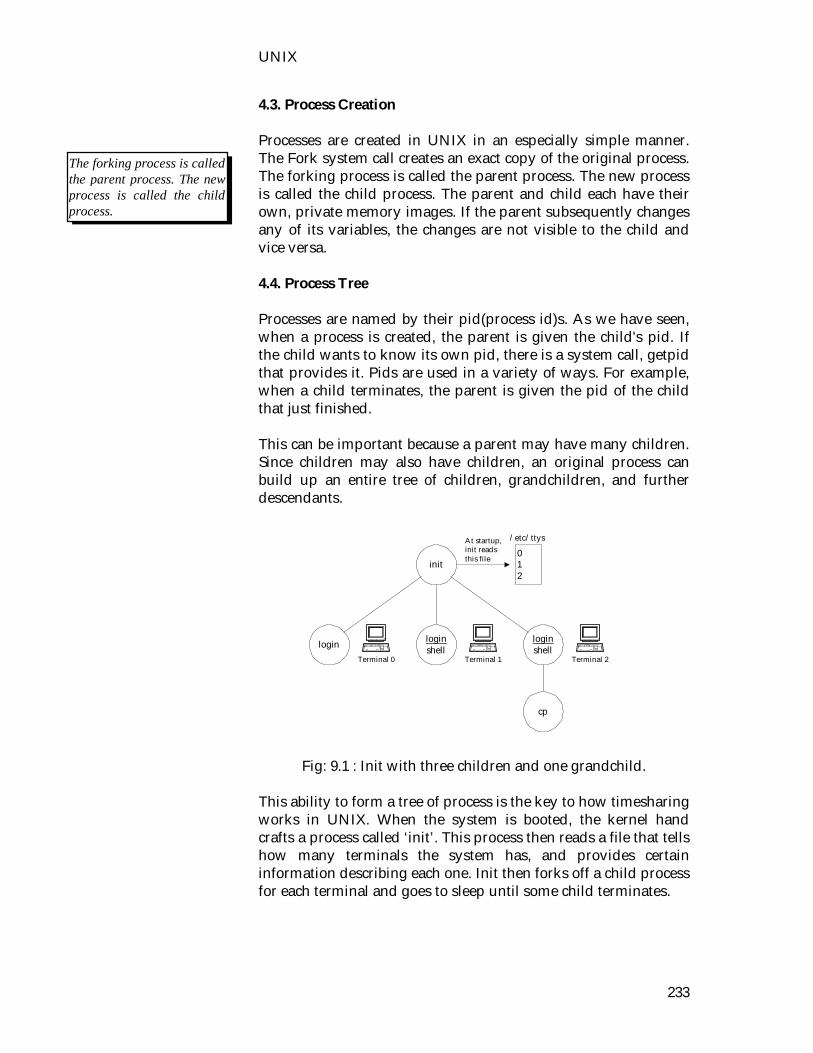
UNIX
233
4.3. Process Creation Processes are created in UNIX in an especially simple manner. The Fork system call creates an exact copy of the original process. The forking process is called the parent process. The new process is called the child process. The parent and child each have their own, private memory images. If the parent subsequently changes any of its variables, the changes are not visible to the child and vice versa. 4.4. Process Tree Processes are named by their pid(process id)s. As we have seen, when a process is created, the parent is given the child's pid. If the child wants to know its own pid, there is a system call, getpid that provides it. Pids are used in a variety of ways. For example, when a child terminates, the parent is given the pid of the child that just finished. This can be important because a parent may have many children. Since children may also have children, an original process can build up an entire tree of children, grandchildren, and further descendants.
Fig: 9.1 : Init with three children and one grandchild.
This ability to form a tree of process is the key to how timesharing works in UNIX. When the system is booted, the kernel hand crafts a process called ‘init’. This process then reads a file that tells how many terminals the system has, and provides certain information describing each one. Init then forks off a child process for each terminal and goes to sleep until some child terminates.
login loginshell
loginshell
init
cp
Terminal 0 Terminal 1 Terminal 2
012
At startup,init readsthis file
/etc/ttys
The forking process is called the parent process. The new process is called the child process.

Operating System
234
Each child runs the login program, which prints. Login on the terminal's and tries to read the user's name from the keyboard. When someone sits down at the terminal and provides a login name, login then asks for a password, encrypts it, and verifies it against the encrypted password stored in the password file. If it is correct login overlays itself with the user's shell, which then waits for the first command. If it is incorrect, login just asks for another user name. This mechanism is illustrated in Fig. 9.1 for a system with three terminals. The login process running on behalf of terminal 0 is still waiting for input. The one running on behalf of terminal 1 has had a successful login, and is now running the shell, which is awaiting a command. A successful login has also occurred on terminal 2, only here the user has started the cp program, which is running as a child of the shell. The shell is blocked, waiting for the child to terminate, at which time the shell will type another prompt and read from the keyboard. 4.5. Communication Between Processes Processes in UNIX can communicate with each other using a form of message passing. It is possible to create a kind of channel between two processes into which one process can write a stream of bytes for the other to read. These channels are called pipes. Synchronization is possible because when a process tries to read from an empty pipe it is blocked until data are available. Shell pipelines are implemented with pipes. When the shell sees a command such as sort < head it creates two processes, sort and head, and sets up a pipe between them in such a way that sort's standard output is connected to head's standard input. In this way, all the data that sort writes go directly to head, instead of going to a file. If the pipe fills up, the system stops running sort until head has removed some data from the pipe. Processes can also communicate in another way: software interrupts. A process can send what is called a signal to another
Processes in UNIX can communicate with each other using a form of message passing.
Processes can also communicate in another way: software interrupts.
UNIX
235
process. Processes can tell the system what they want to happen when a signal arrives. The choices are to ignore it, to catch it, or to let the signal kill the process (default). If a process elects to catch signals sent to it, it must specify a signal handling procedure. When a signal arrives, control will abruptly switch to the handler. When the handler is finished and returns, control goes back to where it came from, analogous to hardware I/O interrupts. A process can only send signals to members of its process group, which consists of its parent (and further ancestors), siblings, and children (and further descendants). A process may also send a signal to all members of its process group with a single system call.
4.6. Exercises 4.6.1. Multiple choice questions 1. In UNIX background processes are called i) daemons ii) parent process iii) child process iv) signal. 4.6.2. Questions for short answers a) Specify a way in which 2 processes can communicate. b) What is a process group? 4.6.3. Analytical question a) Discuss briefly the process control method in UNIX.
Operating System
236
Lesson 5 : File System, Disk and Directory Structure
5.1. Learning Objectives On completion of this lesson you will be able to learn : the file and directory structure of UNIX system access permissions of files and directories devices those act as files. 5.2. The Hierarchical File Structure A hierarchical structure frequently takes the shape of a pyramid. One example of this type of structure is found by tracing a family's lineage: A couple has a child; that child may have several children and each of those children may have more children. This hierarchical structure is called a family tree. Like the family tree it resembles, the UNIX system file structure is also called a tree. It is composed of set of connected files. This structure allows users to organize files so they can easily find any particular one. In a standard UNIX system, each user starts with one directory. From this single directory users can make as many sub-directories as they like, dividing sub-directories into additional sub-directories. In this manner, they can continue expanding the structure to any level according to their needs. 5.3. Directory and Ordinary Files Like a family tree, the tree representing the file structure is usually pictured upside down, with its root at the top. Figures 9.2 and 9.3 show that the tree "grows" downward from the root, with paths connecting the root to each of the other files. At the end of each path is an ordinary file of a directory file. Ordinary files, frequently just called files, are at the ends of paths that cannot support other paths. Directory files usually referred to as directories are the points that other paths can branch off from. Fig. 9.3 and 9.4 shows some empty directories. Directories directly connected by a path are called parents (closer to the root) and children (farther from the root.)
The UNIX system file structure is also called a tree.

UNIX
237
5.3.1. Filenames Every file has a filename. On SunOS and Berkeley UNIX systems you can use as many as 255 characters in a filename; older versions of UNIX had a maximum length of 14 characters. Although you can use almost any character in a filename you will avoid confusion if you choose characters from the following list: Uppercase letters (A-Z) lowercase letters (a-z) numbers (0-9) underscore( _ ) period ( .) comma( ,)
Figure 9.2: Directories and ordinary files.
Fig. 9.3 : The directories of a secretary.
directory
directory directory directory
ordinary file ordinary file
ordinary file
ordinary file ordinary file
directory
directory
correspondence
personal memos business
cheese_co
letter_1 letter_2
milk_co

Operating System
238
The only exception is the root directory, which is always named / and referred to by this single character. No other file can use this name. Like children of one parent, no two files in the same directory can have the same name. Files in different directories, like children of different parents, can have the same name. The filenames you choose should mean something. UNIX systems that support longer filenames are becoming more common. If you share your files with users on other UNIX systems, you should probably make sure that long filenames differ within the first 14 characters. If you keep the filenames short, they will be easy to type and later you can add extensions to them without exceeding the 14-character limit imposed by some versions of UNIX of course, the disadvantage of short filenames is that they are typically less descriptive than long filenames. The length limit on filenames was increased to enable users to select descriptive names. The UNIX operating system is case sensitive however, and files named JANUARY, January, and January would represent three distinct files. 5.3.2. Filename Extensions In the following filenames, filename extensions help describe the contents of the file. A filename extension is the part of the filename following an embedded period. Some programs, such as the C programming language compiler, depend on specific filename extensions. In most cases, however filename extensions are optional. Use extensions freely to make filenames easy to understand. If you like, you can use several periods within the same filename (for example, notes.4.10.88). 5.3.3. Invisible Filenames A filename beginning with a period is called an invisible filename because is does not normally display it. The command Is - a displays all filenames even invisible ones. Startup files are usually invisible so that they do not clutter a directory . Two special invisible entries, a single and double period (. And ..) appear in every directory. These entries are discussed on.
UNIX system support longer file names.
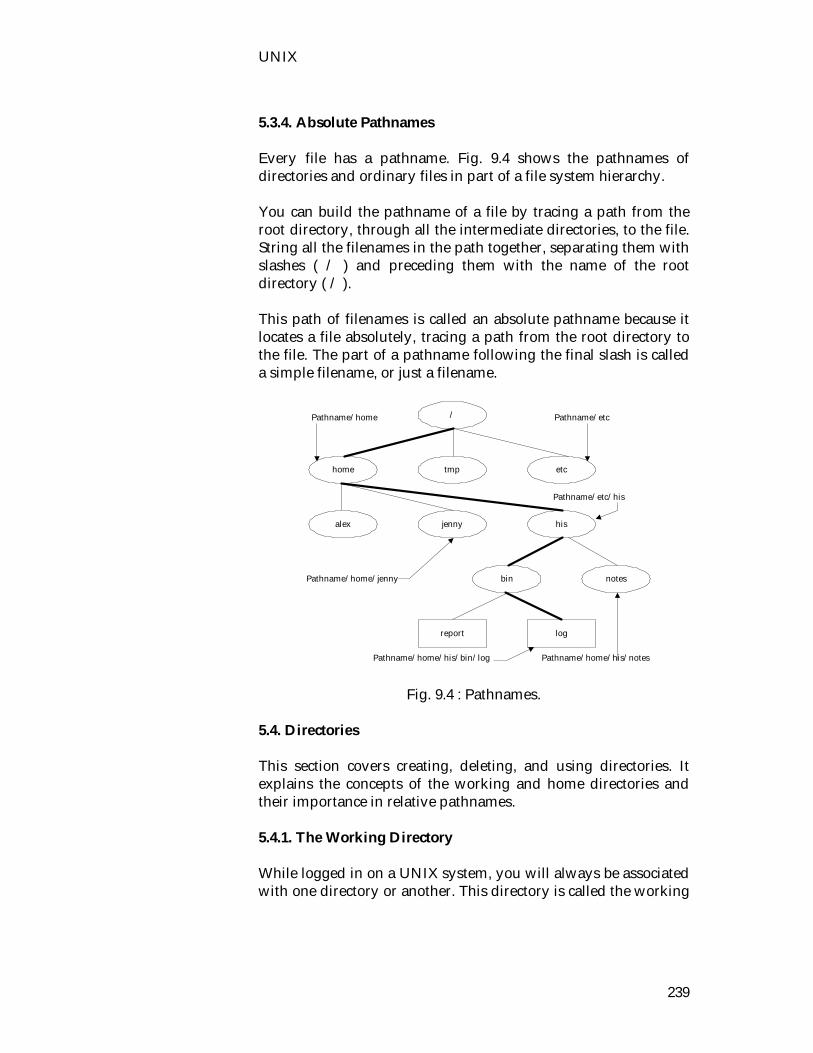
UNIX
239
5.3.4. Absolute Pathnames Every file has a pathname. Fig. 9.4 shows the pathnames of directories and ordinary files in part of a file system hierarchy. You can build the pathname of a file by tracing a path from the root directory, through all the intermediate directories, to the file. String all the filenames in the path together, separating them with slashes ( / ) and preceding them with the name of the root directory ( / ). This path of filenames is called an absolute pathname because it locates a file absolutely, tracing a path from the root directory to the file. The part of a pathname following the final slash is called a simple filename, or just a filename.
Fig. 9.4 : Pathnames. 5.4. Directories This section covers creating, deleting, and using directories. It explains the concepts of the working and home directories and their importance in relative pathnames. 5.4.1. The Working Directory While logged in on a UNIX system, you will always be associated with one directory or another. This directory is called the working
/
home tmp etc
report log
jennyalex his
notesbin
Pathname/home Pathname/etc
Pathname/etc/his
Pathname/home/jenny
Pathname/home/his/bin/log Pathname/home/his/notes

Operating System
240
directory, or the current directory. The pwd (print working directory) utility displays the pathname of the working directory. To access any file in the working directory, name is not needed. It needs only a simple filename. To access a file in another directory, however, a pathname is needed. 5.4.2. Startup Files An important file that appears in home directory is a startup file. It gives the operating system specific information about a user. Frequently, it tells the system what kind of terminal you are using and executes the ‘stty’ (set terminal) utility to establish line kill and erase keys. Either you or the system administrator can put a startup file, containing shell commands, in your home directory, The shell executes the commands in this file each time you log in. With the Bourne Shell and the Korn Shell the filename must be .profile. Use .login with the C Shell. 5.4.3. Creating a Directory The ‘mkdir’ utility creates a directory. It does not change your association with the working directory. The argument you use with mkdir becomes the pathname of the new directory. Fig. 9.5 Shows the directory structure that is developed in the following example. The light lines represent directories that are added. In the following commands mkdir creates a directory named literature as a child of the /home/alex directory. When you use mkdir, enter the absolute pathname of your home directory in place of /home/alex. $ mkdir $ ls demo literature names temp $ls -F demo literature/ names temp $ls literature $
An important file that appears in home directory is a startup file.
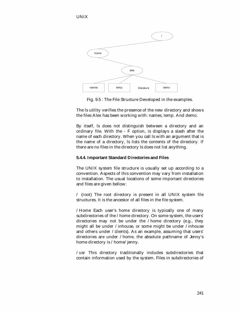
UNIX
241
Fig. 9.5 : The File Structure Developed in the examples. The ls utility verifies the presence of the new directory and shows the files Alex has been working with: names, temp. And demo. By itself, ls does not distinguish between a directory and an ordinary file. With the - F option, is displays a slash after the name of each directory. When you call ls with an argument that is the name of a directory, ls lists the contents of the directory. If there are no files in the directory ls does not list anything. 5.4.4. Important Standard Directories and Files The UNIX system file structure is usually set up according to a convention. Aspects of this convention may vary from installation to installation. The usual locations of some important directories and files are given bellow: / (root) The root directory is present in all UNIX system file structures. It is the ancestor of all files in the file system. /Home Each user's home directory is typically one of many subdirectories of the /home directory. On some system, the users' directories may not be under the /home directory (e.g., they might all be under /inhouse, or some might be under /inhouse and others under /clients). As an example, assuming that users' directories are under /home, the absolute pathname of Jenny's home directory is /home/jenny. /usr This directory traditionally includes subdirectories that contain information used by the system. Files in subdirectories of
/
home
names temp
alex
demoliterature
Operating System
242
/usr do not change often and may be shared by multiple systems. /Usr/bin, /bin These directories contain the standard UNIX utility programs. On some systems, both names are used to refer to the same directory. /Usr/ucb The utilities stored in /usr/ucb were developed at the University of California, Berkeley. You can find the networking utilities here. /etc, /usr/etc Administrative, configuration, and other system files are kept here. The /etc directory typically includes utilities needed during the booting process, and /usr/etc holds those utilities that are most useful after the system is up and running. One of the most important is the /etc/passwd file, containing a list of all users who have permission to use the system. /Var Files with contents that vary as the system runs are found in subdirectories under /var. The most common examples are temporary files, system log files, spooled files, and user mailbox files. Older versions of UNIX scattered such files through several subdirectories of /usr (/usr/adm, /usr/mail, /usr/spool, /usr/tmp). /Dev All files that represent peripheral devices, such as terminals and printers, are kept in this directory. /Tmp Many programs use this directory to hold temporary files. /export A common place to locate files on a file server that are to be shared by many systems (g.g., manual pages and other system files that do not change). 5.5. Access Permissions Three types of users can access a file: the owner of the file (owner), a member of a group to which the owner belongs and everyone else (other). A user can attempt to access an ordinary file in three ways-by trying to read from, write to, or execute it. Three types of users, each able to access a file in three ways, equals a total of nine possible ways to access an ordinary file: The owner of a file can try to : A member of the owner's group can try to:
Three types of users can access a file: the owner of the file (owner), a member of a group to which the owner belongs and everyone else (other).
UNIX
243
Anyone else can try to:� read from the file write to the file execute the file read from the file write to the file execute the file read from the file write to the file execute the file The UNIX system access-permission scheme lets other users access to the files you want to share and keep private files confidential. You can allow other users to read form and write to a file only to read form a file or only to write to a file. Similarly, you can protect entire directories from being scanned. There is an exception to the access permissions described above. The system administrator or another user who knows the special password can log in as the Superuser and have full access to all files, regardless of owner or access permissions. 5.5.1. Directory Access Permissions Access permissions have slightly different meanings when used with directories. Although a directory can be accessed by the three types of users and can be read from or written to, it can never be executed. Execute access permission is redefined for a directory. It means you can search through the directory. It has nothing to do with executing a file. Alex can give the following command to ensure that Jenny, or anyone else, can look through, read files form, write files to, and remove files from his directory named info: $ chmod a+rwx /home/alex/info You can view the access permissions associated with a directory by using the -d (directory), -l, and -g options, as shown in the following example. The d at the left end of the line indicates that /home/alex/info is a directory. $ ls -ldg /home/alex/info drwxrwxrwx 3 alex pubs 112 Apr 15 11:05 /home/alex/info 5.6. Devices

Operating System
244
UNIX maps hard disks as well as terminals and other devices onto special files in the directory /dev of the file systems. Thus the programmer can access such devices in the same way as normal files. Likewise the floppy disk drive ( /dev/fd0), the mouse ( /dev/ mouse), and the hard disk are addressed via an entry in the /dev device drivers directory.
5.7. Exercises 5.7.1. Multiple choice questions 1. A new directory in UNIX file system is created by the
command i) mkdir ii) chdir iii) rmdir iv) cd. 2. If the file access permission of a file is -rw-r--r--, a member
of the owner's group can i) read from the file ii) write to the file iii) execute the file iv) none of the above. 5.7.2. Questions for short answers a) Describe briefly how to use the command 'chmod'. b) Using which command the directory can be created? 5.7.3. Analytical question a) Write a list of all file and directory handling commands
described in this book and discuss briefly how to use each of them.

UNIX
245
Lesson 6 : UNIX Commands 6.1. Learning Objectives On completion of this lesson, you will be able to learn : system and processes user and group management time printing. 6.2. System and processes Free Free displays the current degree of utilization of main memory (in KB). The values in the first line include I/O buffers (buffers for hard disk and floppy disk access as well as inter-process and network communication); the values in the second line (+/-buffers) do not. Fuser File fuser allows you to determine which processes are currently accessing a file. Halt Halts the system. The user should employ shutdown -h instead: otherwise in an error situation the system could halt without shutting down the file system. ps [ -a] [-h] [-j] [-l] [-m] [-r] [-s] [-t] terminal ] [-u] [-w] [-x] Outputs a list of currently active processes. -a displays the processes of all users -h suppresses the header line -j outputs the process's group ID and session ID

Operating System
246
-l verbose output format -m provides an overview of storage allocation -r lists only currently running processes -s provides information on signal status -t terminal displays processes and their controlling terminal -u outputs the name of the process owner and the start time -w suppresses the truncation of command lines for - output -x also displays processor without a controlling terminal
(specially daemons) The flags under STAT have the following meanings. R runnable 9is executing or ready for execution) S sleeping: the process is waiting for an event e.g., new data
from a file or a network connection or user input. D unintrruptable sleep: this process cannot even be
terminated with the signal KILL. This is typical of processes that are currently carrying out disk operations.
T stopped or traced: either the process was halted with the signal STOP or the key combination Ctrl S, or it is presently being analyzed by trace.
W A process that "occupy no main memory" ( Manual page for ps). Either it is a process it file kernel (since it uses kernel memory, it does not occupy any of the main memory pages available for user processes a process whose pages were completely swapped the hard disk (usually ones that have been inactive for a long time.
N This process has a positive note value: it has reduced priority and other processes are invoret over it.
< This process has a negative value: it = with mcreased priority and it is favored over other processes. Only the superuser can assign presses = nice values.
Pstree [-a] pstree lists all processes in a tree according to parent/child. -A The command line that launched the process is displayed
also. Reboot Reboots the system (system shutdown with subsequent reboot). Shutdown -r is more sccure.

UNIX
247
Shutdown [-c] [-h] [-k] [-r sec] time [message] Changes the run level of the system or terminates the system. A time and a warning message can be passed as arguments. For an immediate shutdown, the time now is specified. -c interrupts a shutdown in progress. -h halts the system with the termination of all processes and
unmounts the file systems. -k does not execute a shutdown, but only displays the
warning \ -r reboots the sytstem -t sec delay in seconds between the display of the warning
message and sending the kill signals. Umount [device \directory]
umount unmounts the specified file system, removing it from the directory tree, and completely flushes the I/O buffers to disk. Uname [-a] [-m] [-n] [-r] [-s] [-v] Outputs the name and version number of the current system. -a outputs all available information -m outputs hardware (processor) type -n outputs the host name -r outputs the version number of the operating system -s outputs the name of the operating system -v outputs the date and time of compilation of the kernel uname -sr Linux 2.0.18 uptime Outputs the current time, the time since the last reboot, the number of logged users, and the momentary system load. 11:06pm up 6:59, 3 users, load average: 0.04, 0.05, 0.00 6.3. User and group management chsh

Operating System
248
Changes the shell in which the user lands after logging in. Only certain shells are permissible. The shell's name (with its absolute path) is specilied in /etc/shells. groups [user] Output the groups to which the specified user helongs. A parameterless invocation lists all the current user's own groups, and with a parameter the groups of the specified user. The command evaluates the files /etc/passwd and/etc/groups. Id [-g] [-G] [-n] [-r] [-u] Displays the real and effective user ID (UID) and all groups (GID) of the current user. -g displays only GID -G displays only the additional groups to which a user
belongs -n displays GID or UID as name (only in combination with
options -g,-u,-G) -r displays the real instead of the effective GID (only in
combination with options -g,-u,-G) -u displays only UID last [-f file] [-h host] [-t tty] [-N] [attribute] Provides information from the login statistics (/etc/wtmp). Without additional arguments, it outjputs a list of all login, logout, shutdown, and reboot activities. This list contains the name of the user or the event, the login terminal, the login host, and the time. A selection can be limited to certain entries by specifying search attributes (name, login terminal). -N limits output to a certain number of lines -f file uses the specified file instead of /etc/wtmp as the
database -t terminal list only logins entered from a particular terminal -h host lists only logins entered from a certain host hermes: /root # last uhl uhl ttyp4 mobby Sun Jan 29 17:24 still logged in uhl ttyp2 tonne Sun Jan 29 16:32 - 16:47 (00:15) wtmp begins Sun Jan 29 15:18 hermes : /root #

UNIX
249
passwd [username] Changes the user's own password. The system administrator can also change the passwords of other users. w [-h] [s-s] [-f] [users] Displays all currently logged users and their activities. Without parameters, all users are output; with a name, only the specified users. -h suppresses a title line -f determines whether the login terminal should also be
output -s concise output format who [-i] [-q] [-w] [-H] [file] [am i] Outputs a list of users currently logged in, their terminals, the login time, and the name of the host on which they logged in. If a file name is specified in addition, then this file is used for evaluation instead of /etc/utmp. am I outputs the user's own data -I outputs how long the user was inactive -H outputs column headings -q outputs only the login name and the number of users -w displays whether the user accepts (+) messages generated
with write or not (-) whoami Displays the user name under which the user is currently logged in. 6.4. File and Directory Management These commands are discussed in lesson 5. 6.5. Time at [-b] [-d] [-f file] [-l] [-m] [-qQ] [-V]
Operating System
250
Executes commands at a certain time. The commands are entered at the standard input device and terminated with EOF (Ctrl + D). Option -f permits alternative input from a shell script. A Bourne shell (/bin/sh) is used for execution. Via the option -q individual jobs can be assigned to different ueqes (a-z, A-Z), where letters later in the alphabet reflect decreasing priority. The time can be specified in numeric form (HHMM, HH:MM) or with a keyword such as noon, teatime (16:00), or midnight. Alternatively, the time can be specified as a difference such as now +3 hours. Minutes, hours, days, weeks, months, and years are permissible units. If the job is to run on a certain day, then the mor.... (Jan, Feb, Mar......) and the year (97,. 98...) are specified additionally. - b equivalent to the command batch -d removes the specified jobs from the queue (atrm) -f file executes the commands in file -l list the current user's jobs (atq) -r sends an e-mail tothe user when the commands have been
completed -qQ assigns a job toa particular queue specified in Q 9a-z. A-Z) -V returns the version number cal [-j] [-y] [[month] year] Displays a calendar for the current month or a specified month or year. The number of the year must be given in long form (e.g., 1997) and the month as a number 91-12). -j displays a Julian calendar (with days numbered
sequentially) -y displays a calendar for the current year date [* format] date [-d] [-s date] [-u] [string] In the former form, the current date and time are returned in a format that can be provided optionally. With the second form, the system administrator can set the system time. Output Format %% percent sign

UNIX
251
%n new line %t tabulator %H hour (00..23) %I hour (01..12) %k hour (0..23) %l hour (1..12) %M minute (00..59) %p AM or PM %r gime in 12-hour format (hh:mm:ss[AM:PM]) %s seconds since January 1, 1970, 0:00 %S seconds (00..50) %T time in 24-hour format %x time in local format %z time zone, if defined, else empty %a local abbreviation of day name %A local name of day of week %b local abbreviation of month name (Jan...Dec) %B local month name (January...December) %c local date with time and time zone %d day of month (01..31) %D date (mm/dd/yy) %h identical to %b %j sequential day of the year (001..366) %m month as number (01..12) %U week as number (0053) where Sunday is the first day %w day of week as number (0..6) %W week as number (00...53) where Monday is the first day %x local representation of the date (dd/mm/yy) %y last two digits of the year (00..99) %Y year (1997..) Options -d date outputs the specified date (which can contain the
month name,time zone,...) -s date sets the date in arbitrary format (which can contain the
month name, time zone,...) -u ignores time zome and uses UTC (Universal
Coordinated Time) 6.6. Printing lpc [command [argument]]
Operating System
252
Serves to control printer spoilers. It enables the activation and deactivation of individual printers and their printing queues, shifting printer jobs within the printing queues, and outputting status information. Invoking lpc without an argument produces an interactive command modus. Alternatively, these commands can also be passed to lpc on invocation. Available Commands abort (all|printer) terminates active spoiler(s) and disables the
corresponding printer(s) clean (all|printer) removes all incomplete files form the
specified printer queue(s) disable (all|printer) disables the corresponding printer(s) down (all|printer) turns off the specified queue. disables
printer(s), and writes the specified message in the printer status file. This message is output on invocation of lpq.
Enable (all|printer) enables the specified printer queue(s) and permits the addition of new jobs
exit, quit ends the lpc program help displays a list of available commands restart (all|printer) attempts to restart printer daemon(s) start (all|printer) activates printers(s) and starts printer
daemon(s) for the specified printer(s) status (all|printer) stops the printer daemon on completion of
the current job and disables the printer topq printer [jobs] [user]
places the specified job at the head of the head of the queue
up (all|printer) activates queue(s) and starts printer daemon(s)
lpq -l -p name [jobs] [user] Provides information on the current status of printer queues. -l verbose status report on each job -p name selects a printer queue lpr -#n [-C text] [-h] [-J job] [-m] [-p name] [-r] [-s] [-U user] [files]

UNIX
253
Sends files to a printer queue. Alternatively, data can be printed lpr via the standard input device. Invocation without options outputs to the queue lp. -#n creates n copies of the specified documents -C text prints a job classification on the title page -h suppresses the output of a header before a print job -J job prints a job name on the title page -m sends a mail to the user on completion of the job -P name selects the specified printer queue -r deletes the file after printing (with option -s) -s file is not spooled but linked. Thus the printer file
must not be deleted during printing. -U user prints the user name on the title page lprm --p name [job numbers] [user] Removes entries form a printer queue. Job numbers or user names can be specified as selection criteria. If no argument is specified, the active job is removed. - removes all entries from a queue - p name selects the specified printer queue
6.1. Exercise 6.1.1. Multiple choice questions 1. In this chapter the UNIX commands are described i) SCO UNIX commands ii) Berkeley UNIX commands iii) Xenise commands iv) Linuse commands. 2. A user can get a list of all currently logged users by the
command i) who ii) whoami iii) w iv) id.
6.1.2. Questions for short answers a) What the function of the 'time' command.

Operating System
254
b) How a user can see a tree at all the processor running at a time?
6.1.3. Analytical question
a) Make a list of all the commands described in this chapter and narrate any ten.

Answers to MCQs
255
Answers to MCQs : Unit 1 : Lesson 1 : 1. i), 2. i), 3. ii), 4. i) Lesson 2 : 1. ii), 2. ii), 3. iii) Lesson 3 : 1. ii), 2. iii), 3. iii) Lesson 4 : 1. i), 2. ii) Lesson 5 : 1. iv), 2. ii) Unit 2 :
Unit 4 : Lesson 1 : 1. i) Lesson 4 : 1. i), 2. ii) Unit 5 : Lesson 1 : 1. iii) Lesson 2 : 1. i), 2. i) Lesson 3 :
Unit 7 : Lesson 1 : 1. i), 2. i) Lesson 2 : 1. ii), 2. i) Lesson 3 : 1. ii), 2. i) Lesson 4 : 1. i), 2. ii), 3. i) Lesson 5 : 1. ii), 2. ii) Unit 8 :
Lesson 1 : 1. i), 2. i) Lesson 2 : 1. iii) Lesson 3 : 1. iii), 2. ii) Unit 3 :
1. i), 2. ii) Lesson 4 : 1. iii), 2. i), 3. i) Lesson 5 : 1. i), 2. ii) Unit 6 : Lesson 1 : 1. i), 2. i)
Lesson 1 : 1. iii), 2. ii), 3. i) Lesson 2 : 1. i), 2. ii) Lesson 3 : 1. ii), 2. iv), 3. i) Unit 9 :
Lesson 1 : 1. vi) Lesson 2 : 1. i) Lesson 3 : 1. iv) Lesson 4 : 1. iv), 2. i), 3. i)
Lesson 2 : 1. ii), 2. i) Lesson 3 : 1. iv), 2. ii) Lesson 4 : 1. i), 2. i)
Lesson 1 : 1. ii) Lesson 3 : 1. i) Lesson 4 : 1. i) Lesson 5 : 1. i), 2. iv) Lesson 6 : 1. i), 2. i)

Further Reading
256
Further Reading 1. Silberschatz A., Peterson J. L., Galvin P.B., Operating System
Concepts, Third Edition, Addison Wesley Pub., 1992. 2. Tanenbaum A. S., Operating Systems : Design and
Implementation, Second Edition, Prentice Hall of India, 1992. 3. Milenkovic M., Operating Systems : Concepts and Design,
Second Edition, Mc Graw Hill, INC, 1992. 4. Andrews G. R and Schneider F. B, Concepts and Notations for
Concurrent Programming, Mc Graw Hill, 1982. 5. Bach M. J., The Design of the UNIX Operating System
Prentice Hall Pub., 1986. 6. Calingaert P., Operating System Elements, Englewood Cliffs,
N. J. : Prentice Hall, 1982. 7. Deitel H. M., An Introduction to Operating System, Reading,
Addison Wesley, 1983. 8. Slotnick D. L., Butterfield E. M., Colantonio E. S, Kopetzky
D.J., Slotnick J. K., Computers and Applications : An Introduction to Data Processing, Heath and Company, 1986.

OPERATING SYSTEM
DCA 2302 OPERATING SYSTEM
The basic concept of
operating system is presented as an easy understanding guide
for a self learner. This book illustrates the principles and practice of operating
system design by using suitable algorithms and relevant examples. The features of UNIX
and WINDOWS are introduced to help a learner for practical experience. The
book is suitable for a self learner, students and professionals.
SCHOOL OF SCIENCE AND TECHNOLOGY
BANGLADESH OPEN UNIVERSITY