operating manual - the eraser company · pdf fileoperating manual please call for service or...
TRANSCRIPT

Model K8A Wire Stripper
Please Read Before Operating Unit
Operating Manual
Please Call for Service or Spare Parts
The Eraser Company, Inc.PO Box 4961/ Oliva DriveSyracuse, NY 13221, USA
Phone: (315) 454-3237 Fax: (315) 454-3090
Website: www.eraser.comE-mail: [email protected]
Always Moving Forward®

p 2
Eraser Company Inc. • Syracuse, NY USA • Ph: 315-454-3237 • [email protected] • www.eraser.com • Fax 315-454-3090
ORDERING INFORMATION
UnitAR1641 (K8A) .......................... Air operated stripper, 120V 60Hz, 90 PSI
Blade Selection for Four Blade HeadFor all extruded type insulations:IR0318 .......................... Flat front blades (set of four) for 38-8 AWG (0.10-3.25mmø) wires or up to 3/8” (9.5mmø) diameter over insulation
Use only for wires with hard or thin insulation:IR0337 .........................Blades with relief (set of four) for 38-8 AWG (0.10-3.25mmø) wires or up to 3/8” (9.5mmø) diameter over insulation
Use only for thick or rubbery insulations: Machine must be used in counter clockwise rotation.
For film and magnet wires (all sets of four):IR0319 .........Wire sizes 11-15 AWG (2.31-1.45mmø)IR0321 .........Wire sizes 16-20 AWG (1.30-0.81mmø)IR0323 .........Wire sizes 25-28 AWG (0.46-0.33mmø)IR0324..............Special blades available for unusual insulations and applications. Material sample required for sizing.
ROTARY BLADE STRIPPER FOR EXTRUDED OR MAGNET WIRE
OPTIONAL PARTSPR0139............................................. Spare drive beltPR0137.... Replacement blade opening garter springPG0291 ...................... Replacement blade pivot pinsPR0689............ Replacement plexiglass blade guard
For a free application evaluation, send 3 - 5 feet of wire or cable along with stripping specifications to our Customer Service Department.
Always Moving Forward®
SPECIFICATIONS
Model - K8A
Wire Size:Extruded Wires and Built-Up Insulations ... 38-8 AWG (0.10-3.25mmø) or up to 3/8" OD (9.5mmø) Film Insulated and Magnet Wires ............ 28-11 AWG (0.33-2.31mmø)
Strip Lengths:Extruded Wires and Built-Up Insulations ... 0 to 1 3/8" (0-34mm)Film Insulated and Magnet Wires .............. 0 to 1 3/8" (0-34mm)Infinite strip lengths possible if length stop is removed
Power .................... Air operated, 120V 60Hz, 90PSIDecibel rating............................................... 60 dB(A)
Size:Unit .... 14" x 9 7/8" x 9" (356mm x 251mm x 229mm)Foot switch assembly K8A.................. 6" x 6" x 4 1/2" (152mm x 152mm x 114mm)
Weight:K8A ................................................... 34lbs. (15.4 Kg)

p 3
Eraser Company Inc. • Syracuse, NY USA • Ph: 315-454-3237 • [email protected] • www.eraser.com • Fax 315-454-3090
Model K8A Wire StripperIMPORTANT! DO NOT OPERATE MACHINE UN-TIL YOU HAVE READ THOROUGHLY, AND UN-DERSTAND COMPLETELY, ALL PRECAUTIONS, INSTRUCTIONS AND INFORMATION ON THESE PAGES. THIS MANUAL CONTAINS IMPORTANT SAFETY AND OPERATING INSTRUCTIONS. IT SHOULD BE RETAINED WITH THE MACHINE FOR FUTURE REFERENCE.
SAFETY PRECAUTIONS - MECHANICAL
! DO NOT OPERATE UNIT WITHOUT GUARDS IN PLACE OR WITH DAMAGED GUARDS.
! DO NOT DEFEAT ANY OF THE SAFETY FEA-TURES.
! DO NOT PLACE FINGERS OR APPENDAGES NEAR MOVING PARTS OR IN OR NEAR OPEN-INGS IN GUARDS.
SAFETY PRECAUTIONS - ELECTRICAL
! ALWAYS UNPLUG UNIT FROM POWER SUPPLY PRIOR TO ANY MAINTENANCE.
! DO NOT RUN UNIT WITH INCORRECT LINE VOLTAGE.
! NEVER RUN MACHINE WITH DAMAGED OR WORN POWER CORD.
! NEVER MODIFY THE PLUG PROVIDED. IF IT WILL NOT FIT INTO THE OUTLET, HAVE THE PROPER OUTLET INSTALLED BY A QUALIFIED ELECTRICIAN.
GROUNDING INSTRUCTIONS. Grounding provides a common return path for electric current to reduce the risk of electric shock. This machine is supplied with an electric cord with an equipment-grounding conductor and a grounding plug. The plug must be plugged into a matching outlet that is properly installed and grounded in accordance with all local codes and ordinances.
Improper connection of the equipment-grounding conductor can result in a risk of electric shock. Check with a licensed electrician if in doubt as to whether the machine is properly grounded.
BLADE SPECIFICATION
Stripping blades are precisely made in sets of four to insure correct stripping. Dimension is very important when stripping magnet wires and is closely controlled. Dimension varies for different magnet wire sizes to insure tip of blade is correctly aligned to wire (i.e. when tip is stripping insulation it will be parallel with the wire conductor.)
BLADE SHARPENING SERVICEWe offer a blade re-grinding and re-tipping service. Blades are precisely ground in matched sets on fixtures to insure correct stripping dimensions are maintained. Re-grinding without the use of fixtures will be detrimental to the operation of the blades. Return blades in sets of four to our factory for re-grinding.
OPERATION

p 4
Eraser Company Inc. • Syracuse, NY USA • Ph: 315-454-3237 • [email protected] • www.eraser.com • Fax 315-454-3090
Model K8A Wire StripperEnsure proper alignment of moving parts. Check for any binding of moving parts, breakage of parts, and any other condition(s) that may affect operation. Any damaged part(s) should be properly repaired or replaced prior to any continued use of the machine.
ONLY ALLOW TRAINED AND QUALIFIED PER-SONNEL TO OPERATE UNIT. Always keep these instructions within reach of the machine.
USE RECOMMENDED ACCESSORIES ONLY. Consult this operating manual for recommended accessories. Use only parts supplied by The Eraser Company, Inc. Use of improper accessories will void Eraser’s warranty and may increase risk of injury.
ALL REPAIRS SHOULD BE PERFORMED BY AN ERASER COMPANY REPRESENTATIVE ONLY. Unauthorized disassembly of machines will void Eraser’s warranty.
WHEN USING MACHINERY, ALL SAFETY PRE-CAUTIONS – INCLUDING, BUT NOT LIMITED TO, THOSE LISTED ABOVE - SHOULD BE FOL-LOWED TO REDUCE THE RISKS OF FIRE, ELEC-TRIC SHOCK, AND PERSONAL INJURY, AND DEATH.
IMPORTANT: NO LIABILITY WILL BE INCURRED BY THE ERASER CO. FOR INJURY, DEATH, OR PROPERTY DAMAGE CAUSED BY A PRODUCT WHICH HAS BEEN SET UP, OPERATED, AND/OR INSTALLED CONTRARY TO ERASER’S WRITTEN OPERATING MANUAL, OR WHICH HAS BEEN SUBJECTED TO MISUSE, NEGLIGENCE, OR AC-CIDENT, OR WHICH HAS BEEN REPAIRED OR ALTERED BY ANYONE OTHER THAN THE ERAS-ER COMPANY, OR WHICH HAS BEEN USED IN A MANNER OR FOR A PURPOSE FOR WHICH THE PRODUCT WAS NOT DESIGNED.
SAFETY FIRST - USE BEST PRACTICES
ALWAYS USE SAFETY GLASSES. Everyday eye-glasses only have impact resistant lenses; they are NOT safety glasses. Also use face or dust mask if cutting operationis dusty.
REMOVE ADJUSTING KEYS AND WRENCHES. Form a habit of checking to see that keys and ad-justing wrenches are removed from machine before turning it on.
KEEP WORK AREA CLEAN. Cluttered areas and benches invite accidents. Always leave at least 12” (305 mm) of space around all sides and top of unit.
DON’T USE IN DANGEROUS ENVIRONMENTS. Do not use or locate machine in high-humidity envi-ronments, or expose to rain. Keep work areas well lighted.
WEAR PROPER APPAREL. Do not wear loose clothing, such as gloves, neckties, rings, bracelets, necklaces or any other clothing or jewelry that might get caught in moving parts. This is not an all-inclu-sive list. Wear protective hair covering to contain long hair. Non-slip footwear is recommended.
DON’T OVERREACH. Maintain proper footing and balance at all times.
MAINTAIN BLADES WITH CARE. Keep blades sharp and clean for optimal performance. Follow instructions for lubricating and changing blades and all accessories.
DISCONNECT MACHINE FROM POWER SUPPLY. Unplug the unit before servicing and when changing accessories.
DO NOT EXCEED THE UNIT’S MAXIMUM MATE-RIAL SPECIFICATIONS. Eraser’s warranty will be null and void if machine has been used in any man-ner that is contrary to these instructions.
CHECK FOR DAMAGED PARTS. Before continued use of the machine, the guard and all moving parts should be carefully inspected to ensure that nothing is damaged.

p 5
Eraser Company Inc. • Syracuse, NY USA • Ph: 315-454-3237 • [email protected] • www.eraser.com • Fax 315-454-3090
air supply. Mount the unit securely to the bench, and place the electrical footswitch on the floor.
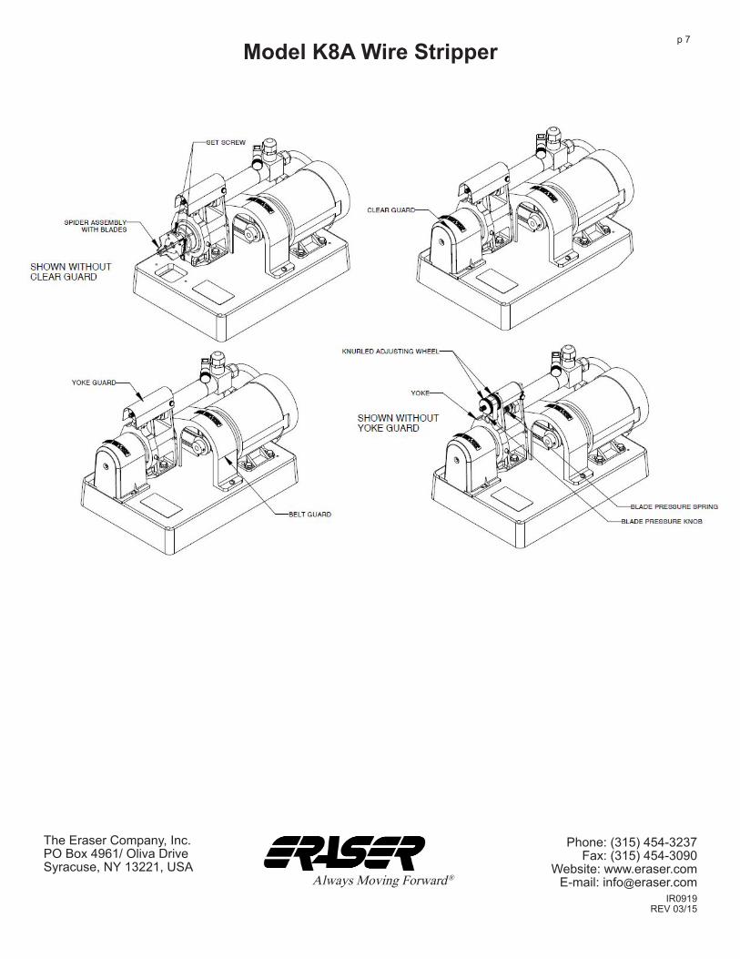
With the blades installed and the unit securely mounted to the bench, blade adjustments may be made for the wire to be stripped. The K8A contains 2 knurled adjusting wheels located on either side of the yoke at the top of the unit. These are covered by a guard. The front wheel controls how far the blades are allowed to close, and the back wheel controls how far they are allowed to open. On the K8A, the blades are open, and the electrical footswitch is activated to close them.
To adjust the wheels, first remove the guard covering them. Loosen the set screws in each of the 2 adjusting wheels using the 5/64" allen wrench. The 2 wheels should be adjusted so that the blades open just far enough to admit the wire to be stripped, and close just far enough to complete the desired stripping, without nicking or damage to the conductors. By restricting the movement of the blades in this manner, they form their own wire guide for the wire being stripped, and the operator will find insertion and withdrawal of the wire much easier. Once these 2 wheels have been set in the approximate desired location by eye, retighten the set screws so the settings will not drift when the unit is turned on. Replace the guard.
The strip length stop rod is located in the center of the shaft and extends through the back of the belt guard. To adjust the strip length rod, first remove the blade guard. Turn the shaft manually to locate the set screw on the shaft. Using an allen wrench, loosen the set screw and slide the rod from behind to the desired location relative to the blades. Retighten the set screw.
NOTE: If window stripping is desired when using the four-blade head, the strip length rod may be completely removed to allow the wire to pass through the unit and be stripped continuously. Replace the blade guard onto the unit.
At the top center of the unit is located the blade pressure spring and knob. If the yoke will not move all the way forward to close the blades, then increase the spring pressure slightly to force more pressure on the yoke. Conversely, if the blades will not open all the way when the footpedal or hand
Model K8A Wire Stripper
OPERATING INSTRUCTIONS
SET-UP:
The K8A is shipped with a spider assembly and 2 allen wrenches, 1/16" and 5/64". Required blade sets must be purchased separately, see "Blade Selection" in this manual. NOTE: It is very important that the proper blades are used for different wire types and sizes to ensure maximum results. See blade selection information on previous page for proper blade selection. The first step is to install the spider assembly and blades onto the machine. Refer to the appropriate instructions below for the four-blade head.
FOUR-BLADE HEAD SET-UP: To install the blades into the spider, first remove each of the 4 pivot pins from the spider by loosening the set screws holding them in place with the 1/16" allen wrench provided. One at a time, insert the 4 blades into the slots of the spider and replace the pivot pins. Be sure the spider is oriented so the set screws in the front of the spider face the tips of the blades. Retighten the pivot pin set screws. Place the garter spring around the notches at the back of the 4 blades, and connect the ends of the spring together.
To install the spider assembly with blades onto the unit, first remove the clear guard of the unit by loosening the 2 screws anchoring the assembly to the base of the unit. Slide the guard forward and lift off. Slide the spider assembly with blades onto the shaft, ensuring that the 2 set screws on the spider line up with the 2 flats on the shaft. Hold the 4 blades in a closed position while sliding the assembly onto the shaft to ensure that the backs of all 4 blades rest on the cone at the back of the shaft. The spider assembly should be firmly seated against the shoulder on the shaft. Securely tighten the 2 set screws holding the spider assembly onto the shaft, with the 5/64" allen wrench provided, then tighten the 2 set screws on the front of the spider assembly. Replace the clear guard onto the unit.
The K8A must be connected to a 90 PSI air supply. The unit’s air cylinder is supplied with a 1/8" female NPT connector. The user must provide a 1/8" male NPT connector and air hose connected to a 90 PSI

p 6
Eraser Company Inc. • Syracuse, NY USA • Ph: 315-454-3237 • [email protected] • www.eraser.com • Fax 315-454-3090
Model K8A Wire Stripperlever is depressed, or if they open with difficulty, then reduce the spring pressure slightly.
Plug the power cord into the IEC connector located at the back of the unit. Plug the unit into the appropriate properly grounded electrical supply.
OPERATION:Turn the unit ON. If stripping wire with extruded or built-up insulation with the four-blade head, run the unit in the same rotation as the lay of the strands in the wire being stripped, either clockwise or counter-clockwise. If stripping film insulated wire with the four-blade head, the rotation is not important. However, changing the rotation from time to time will help increase blade life when stripping film insulated wires.
On the K8A, the blades will be in their open position when the unit is turned on. Insert the wire, and depress the electrical footswitch to close the blades and strip the wire. Release the footswitch to allow the blades to re-open.
Further adjustments to the blade opening and closing knobs and spring pressure knob may be made while the unit is running, if necessary. Ensure that the set screws in the knobs are securely tightened once the proper adjustments have been found, to eliminate drifting.
MAINTENANCE:Keep the unit clean at all times. Periodically apply light oil to the 3 pivot points of the yoke and between the cone and shaft. If oil causes wire insulation to gum up on the yoke or cone, then use a dry lubricant such as graphite. Examine the drive belt periodically for wear, and replace if necessary. Replace blades when dull.
NOTE: Blades on the four-blade head may be resharpened only in their original set of 4. The blade set must be returned to the factory for resharpening.
These blades may also be retipped when resharpening is no longer possible. Contact factory for details.
TROUBLESHOOTING:
PROBLEM: Wire is difficult to insert.SOLUTION: Adjust blade opening setting to a larger or smaller opening as necessary.
PROBLEM: Blades do not open, or open sluggishly.SOLUTION: Check for accumulation of foreign matter or corrosion in the slots of the spider and/or blades. Clean out or sand lightly to remove corrosion.
PROBLEM: Inconsistent Strips.SOLUTIONS: 1) Check consistency of wire diameter.2) Ensure that both adjusting wheels are secured
with the set screw. 3) Ensure that the threaded shaft that the adjusting
wheels are mounted on is secure. 4) Check the condition of blades, and replace if worn. 5) Check that the spider assembly is securely
seated on the shoulder of the shaft and the set screws are securely tightened.
IR0919REV 03/15
p 7
Phone: (315) 454-3237 Fax: (315) 454-3090
Website: www.eraser.comE-mail: [email protected]
The Eraser Company, Inc.PO Box 4961/ Oliva DriveSyracuse, NY 13221, USA
Always Moving Forward®
Model K8A Wire Stripper