operating manual t 300 t400 te series diesel engine · i t-300 air curtain trench burner with...
TRANSCRIPT

Factory and Main Office
Air Burners, Inc.
4390 SW Cargo Way
Palm City, FL 34990
Phone: 772-220-7303 or 888-566-3900
FAX: 772-220-7302
E-mail: [email protected]
© 1998-2018 Air Burners, Inc. The words Air Burners and the Air Burners Logo are Registered Trademarks of Air Burners, Inc. All Rights Reserved. Subject to change without notice. Dimensions & metric conversions rounded.
Visit Our Web Site at:
www.AirBurners.com
(Vers. 01.2018c)
Operating Manual
T-300 Equipped With Perkins 404D.22T or Kubota V2403-TE Series Diesel Engine
Model Year 2017/2018
Air Curtain Burner
Trailer Mounted Trench Burner
“Better Economically - Better Environmentally”

This Page intentionally left blank.

T-300 Air Curtain Trench Burner with Perkins 404D.22T or Kubota V2403-TE Engine
OPERATING MANUAL
INDEX
THE PRINCIPLE OF AIR CURTAIN INCINERATION ..................................... Page 1
GENERAL DESCRIPTION T-300 MODEL ..................................................... Page 2
SAFETY CONSIDERATIONS ......................................................................... Page 4
T-300 COMPONENTS .................................................................................... Page 7
HOW TO SET UP THE MACHINE T-300 UNIT .............................................. Page 8
T-300 WINCH OPERATION ........................................................................... Page 11
HOW TO BUILD A PIT .................................................................................... Page 12
HOW TO OPERATE THE MACHINE .............................................................. Page 14
SITE PREPARATION ..................................................................................... Page 16
LOADING AND STARTING THE FIRE ........................................................... Page 19
HOW TO FEED THE FIRE ............................................................................. Page 22
HOW TO BURN FIRE DOWN FOR SHUTDOWN .......................................... Page 23
HOW TO CLEAN OUT THE PIT ..................................................................... Page 24
HOW TO PREPARE THE MACHINE FOR TRANSPORT .............................. Page 25
TROUBLESHOOTING .................................................................................... Page 26
MAINTENANCE AND CARE OF THE T-300 UNIT ......................................... Page 27
INSTALLATION OF AIR FAN V-BELTS ………………………………………. Page 28
MAINTENANCE AND CARE OF THE MANIFOLD ......................................... Page 29
OPENING COWLING FOR MAJOR MAINTENANCE .................................... Page 30
SERVICING SPECIFICATIONS — PERKINS ENGINE .................................. Page 31
SERVICING SPECIFICATIONS — KUBOTA ENGINE ................................... Page 32
TRAILER TOWING CHECKLIST .................................................................... Page 33
TRAILER WIRING DIAGRAM ........................................................................ Page 34
i

T-300 Air Curtain Trench Burner with Perkins 404D.22T or Kubota V2403-TE Engine
OPERATING MANUAL
ii
T-Series Trench Burner
T-Series Trench Burners

Page 1 of 34 (Vers. 01.2018c)
T-300 Air Curtain Trench Burner with Perkins 404D.22T or Kubota V2403-TE Engine
OPERATING MANUAL
PRINCIPLE OF AIR CURTAIN INCINERATION Air curtain incinerators are designed primarily as a pollution control device. Using a Diesel engine driven fan, these machines generate a curtain of air with a very particu-lar mass flow and velocity. This curtain of air acts as a trap over the top of an earthen trench or thermo-ceramic lined pit. The wood debris is dumped into the trench or pit and then ignited (usually with a propane torch or with a small amount of Diesel fuel) just as you would light any other pile of wood you intended to burn. Once the fire has gained strength the air curtain is turned on. The air curtain traps most of the smoke particles and causes them to re-burn under the air curtain where the temperatures ex-ceed 1,800º F. These machines do not inject any fuels into the fire, the fire is sustained only by adding more wood debris. The air from the air curtain is not heated. The only fuel used in the continuous operation is that of the Diesel engine driven fan.
1. Manifold and nozzles that create the air curtain over the refractory lined pit.
2. Wall of earthen pit (best 30 ft long, 10 ft wide & min 10 ft deep).
3. Material to be burned.
4. High velocity “air curtain” over fire.
5. Continued air flow over-oxygenates fire keeping temperatures high.

Page 2 of 34 (Vers. 01.2018c)
T-300 Air Curtain Trench Burner with Perkins 404D.22T or Kubota V2403-TE Engine
OPERATING MANUAL
GENERAL DESCRIPTION T-300 SERIES
The T-300 is a mobile air curtain burner which is used in combination with an earth-en pit or trench made to function as the combustion chamber. The T-300 unit is a fully self-contained, trailer mounted system that includes a power plant, mechanical drive system, blower fan, manifolds, carrier pipe and fuel tanks. This unit does not require assembly on site, as the carrier pipe and manifolds deploy and unfold. The Diesel engine drives a fan which produces high velocity air. This high velocity air is directed down the carrier pipe to the manifold. The carrier pipe is an important safety element, as it gives the machine the required “set-back” from the fire. This set-back will help protect the machine, if the fire gets too high or if the wind changes direction. Once in the manifold, the air is evenly distributed across the burning trench through the manifold nozzles. Air is directed across the top and down into the combustion zone. The curtain of air acts as a top over the pit, trapping particulates (PM or small airborne particles) and adding oxygen to the combustion zone, thereby generating a hotter more complete fire. Temperature achieved by this unit while burning clean wood and other vegetative waste can range between 1,600º F and 1,800º F. The air flow coupled with the recommended dimensions of the pit, creates an after-burner effect. By re-circulating the air under the curtain, residence time of the partic-ulates is increased long enough for their effective combustion with very little smoke escaping.
T-300 Carrier pipe fully extended T-300 Carrier pipe with manifolds folded

Page 3 of 34 (Vers. 01.2018c)
T-300 Air Curtain Trench Burner with Perkins 404D.22T or Kubota V2403-TE Engine
OPERATING MANUAL
All of this is carefully engineered to provide the correct amount of air at the correct velocity. It is sometimes thought that more air flow will actually increase the burn rate. This is INCORRECT. Modifying the air flow will actually have the opposite effect and reduce the machine’s through-put. Additionally it will reduce the ma-chine’s ability to meet air quality minimum standards. There is a maximum rate at which wood can burn. Trying to exceed that rate by adding more air to an air cur-tain burner causes two major problems: 1) It will cool the fire reducing combustion efficiency creating more smoke (carbon
dioxide and nitrogen enriched). This will begin a circular effect of further reduc-ing the oxygen and further reducing combustion efficiency. The result is your through-put drops and smoke increases.
2) Increasing the air flow beyond design standards will over pressurize the pit causing larger sized particles to be ejected from the pit. Besides violating the EPA limits for PM (particulate matter) the larger hotter embers ejected will pose a much greater fire hazard.
T-300 Specifications
Model Overall Size
L × W × H Trench Size L × W × D
Weight
(Tongue)*
Fuel Consumption**
gal/hr
T-300 28' × 8' 3" × 6' 10" 30' × 10' × 10’ 6,500 lbs. (750 lbs.)
2.5
*) Hitch Select Appropriate Class Hitch for Trailer Towing
**) Diesel Engine Version: Perkins 404D.22T or Kubota V2403-TE (Tier 4 compliant). Diesel fuel consumption rated at aver-age operating RPM and is approximate. Drive System: PTO & multi-belt drive.
NOTE: All weights and dimensions are approximate. Subject to change without notice.

Page 4 of 34 (Vers. 01.2018c)
T-300 Air Curtain Trench Burner with Perkins 404D.22T or Kubota V2403-TE Engine
OPERATING MANUAL
The Air Curtain Burner operator is dealing with fire on a daily basis; it is very important that each and every individual involved with the machine be aware of and practice very rigid safety precautions. When you are running the machine, you are responsible for assuring that it is operated in the safest possible manner at all times. During the burning operations there may not be any signs of smoke from the trench, but small hot embers will always be coming out. These embers rise up on the hot gases from the fire. Operators must be aware of the area around the unit to insure “spot fires” do not ignite. If you notice something wrong, correct it immediately, and if you cannot correct it, find someone who can and/or shut down the machine. The T-300 is very safe as long as it is used and operated in the manner for which it was designed; however, it will be no safer than an open fire burning above ground when it is not being used and operated properly.
Basic Safety Points:
1. Personnel should not enter the pit while building it. There is always the danger of the pit collapsing. Personnel should not enter the pit. The pit should be secured and marked to prevent anyone from falling in. 2. Once the pit is in use the area should be restricted. The area around the pit should be controlled by the trained operators. If the pit is to be re-used the next day, then a security guard and secure fencing should be used around the pit to insure no animals or humans will fall in. If the pit is not to be reused then the fire should be extinguished and the pit filled in with dirt. The operators must monitor the activities around the pit at all times.
3. The Machine must only be operated with the cowling closed and secured. The top cowling provides a guard for the drive belts and fan inlet. There is a risk of se-rious injury, if the machine is run with the cowling open.
SAFETY CONSIDERATIONS
READ ALL SECTIONS OF THIS MANUAL BEFORE YOU BEGIN BURNING OPERATIONS
DANGER: Falling into the fire pit will cause serious injury or death.
DANGER: Watch for DANGER NOTICES throughout this manual.

Page 5 of 34 (Vers. 01.2018c)
T-300 Air Curtain Trench Burner with Perkins 404D.22T or Kubota V2403-TE Engine
OPERATING MANUAL
4. The Machine should be placed on cleared, level ground. The placement or positioning of the machine on the job site can be very important. The machine should be placed in a manner to give the greatest clearance on the downwind side of the pit. The unit should be placed on level ground to facilitate proper positioning of the manifold alongside the pit. 5. The Machine should be placed such that no combustible material is within a minimum of 100 foot clearance in any direction. The machine should not be located over combustibles, such as dry grass, brush or peat moss. In addition, hot embers will escape from the pit and, depending on the wind, will land on the ground around the unit. The unit should not be located within 100 feet of any combustible material. The waste material to be burned during the day’s operation can be staged within the 100 foot perimeter to facilitate loading. The operator must monitor the loading pile to insure embers do not ignite the loading pile. The combustible materials to be stored for burning at a later date must be stored outside the 100 foot perimeter or in accordance with the chart below which suggests adjustments for wind speed.
DANGER: The above distances serve as a GUIDELINE ONLY! You MUST ALWAYS observe the down range area regardless of the wind speed. You must always observe local fire ordinances and directives from the local fire department or other authorities.
WIND SPEED VS. SAFE DISTANCE
Approximate Safe Distance for:
Wind Speed
(MPH)
Structures
(Houses, etc.)
Woods/Trees
Stored Brush Piles
10
300'
150'
100'
12
300'
150'
100'
14
300'
200'
150'
16
400'
250'
150'
18
400'
250'
200'
20
500'
250'
200'

Page 6 of 34 (Vers. 01.2018c)
T-300 Air Curtain Trench Burner with Perkins 404D.22T or Kubota V2403-TE Engine
OPERATING MANUAL
6. The Machine should not be operated when the wind speeds reach 20 MPH. As an operator you should always be aware of wind speed and direction. Increased wind speed will affect the integrity of the “air curtain” and will cause hot embers to trav-el farther. See the wind speed chart on Page 5 regarding the suggested set back. 7. NEVER use highly combustible materials to light the pit. Highly combustible materials such as gasoline, refined spirits, etc. ignite at an explo-sive rate which may cause serious injury or death. The safest method to start the fire in the pit is to use materials, such as paper and kindling wood. In the absence of these materials or when starting materials with a high moisture content, Diesel fuel oil is an acceptable option. 8. Shut the unit down in an emergency. Stop loading the pit, stop the air flow by either disengaging the PTO or by shutting down the engine. Dump dirt, sand or water into the fire pit. 9. Personal Safety Operators need to be aware of the following potential hazards: A) Flying hot embers being released from
the fire. Operators or anyone within the 100 foot radius of the fire should wear ap-propriate fire resistant clothing. The ideal outwear for an operator would include a Nomex jacket, leather gloves, eye protec-tion, hard hat, cotton work jeans and steel toe boots. Operators should never wear synthetic material (i.e. polyester) around the fire as this type of material can melt and cause injury. Additionally, some syn-thetic materials will support combustion and could be very dangerous around fire. One hundred percent cotton materials would be the minimum, cotton treated with a fire retardant would be better and fire proof materials, like “Nomex”, would be best.
B) Noise, ear protection is recommended around the machines. It is a good prac-
tice to wear approved ear protection when working in close proximity to the fan and engine.
C) Ash and dust can be released during the operation and during cleaning. Opera-
tors should wear appropriate breathing masks to protect themselves from inhaling the dust and ash.

Page 7 of 34 (Vers. 01.2018c)
T-300 Air Curtain Trench Burner with Perkins 404D.22T or Kubota V2403-TE Engine
OPERATING MANUAL
T-300 COMPONENTS
T-300 positioned at trench T-300, manifold assembly retracted
T-300 Manifold Extended

Page 8 of 34 (Vers. 01.2018c)
T-300 Air Curtain Trench Burner with Perkins 404D.22T or Kubota V2403-TE Engine
OPERATING MANUAL
DANGER: THE MACHINE MUST ONLY BE OPERATED WITH THE WHEELS CHOCKED AND THE COWLING CLOSED AND SECURED. IF THE MACHINE IS OPERATED WITH THE COWLING OPEN, THEN THE DRIVE BELTS AND FAN INLET ARE UN-GUARDED, AND THERE IS THE RISK OF SERIOUS INJURY.
HOW TO SET UP THE MACHINE
Cowling Latches
1. Once the machine is in the correct loca-tion, first chock the wheels with suitable blocks or wedges to keep the trailer from moving, disconnect your tow vehicle. Next remove the two jacks from the stor-age box under the top cowling and fit them to the jack points at the rear and front of the trailer. Using the three jack stands, level the trailer.
2. Lift the cowling of the machine and se-
cure it with an appropriate cowling sup-port prop rod / device.
3. Check engine fluid levels, top up as nec-
essary. 4. Check drive belts (see Page 29). 5. Check PTO and fan bearings for grease,
re-grease per maintenance schedule. 6. Check engine for leaks, check for any
loose components and any obstructions at the fan inlet.
7. Close the top cowling and secure all
latches (See Photo on right). Lock “D” lift latch.
“D” lift latch

Page 9 of 34 (Vers. 01.2018c)
T-300 Air Curtain Trench Burner with Perkins 404D.22T or Kubota V2403-TE Engine
OPERATING MANUAL
8. Use the jacks to set the trailer level. 9. Remove the carrier pipe locking bolt,
use this bolt to secure the manifold in step 12. NOTE: When the T-300 first arrives, the locking bolt is replaced with a “travel bolt assembly” for flatbed truck transport. Remove this device before first use and replace it with the locking bolt shown here. You will find it in a pouch in the “Black Binder” that con-tains the Operating Manual (Shipped in the T-300 tool box).
10. Release the front winch and extend the carrier pipe manually by pulling the grab handles. Do not use any equipment or machinery to accomplish this.
11. Extend the carrier pipe completely until
the yellow/black arrow indicator shows full extension and you reach a hard stop.
DANGER: IF THE TRAILER IS NOT SET LEVEL THEN THERE IS THE RISK THAT THE CARRIER PIPE WILL EXTEND OUT OF CONTROL AS SOON AS THE LOCKING BOLT IS REMOVED. THIS COULD CAUSE SERIOUS INJURY OR DAMAGE TO THE UNIT.
Carrier pipe locking bolt
Carrier pipe grab handles
DANGER: THE REAR JACK STANDS MUST BE EXTENDED BEFORE PULL-ING THE MANIFOLD OUT, OR THE MACHINE WILL TIP BACK AND YOU COULD BE SERIOUSLY INJURED.

Page 10 of 34 (Vers. 01.2018c)
T-300 Air Curtain Trench Burner with Perkins 404D.22T or Kubota V2403-TE Engine
OPERATING MANUAL
12. Swing the manifolds out and secure them by fitting the locking bolt from Step 8.
13. Lower the two rear jacks so that the
manifold rests squarely on the ground. 14. With the machine and manifold posi-
tioned, you can now mark-out the di-mensions for the pit.
NOTE: THE FRONT OF THE TRAILER WILL RISE. THIS IS NORMAL.
Locking bolt at center of the manifold
Rear Jack stands
T-300 Carrier pipe fully extended
and manifold on the ground
T-300 Carrier pipe fully extended,
Manifolds partially extended

Page 11 of 34 (Vers. 01.2018c)
T-300 Air Curtain Trench Burner with Perkins 404D.22T or Kubota V2403-TE Engine
OPERATING MANUAL
A. WINCH OPERATION FOR PULLING OUT MANIFOLD/CARRIER PIPE ASSEMBLY
1. Level trailer.
2. Release ratchet by pushing the ratchet release lever
forward-down (See Photo on right).
3. Proceed with manifold extraction following the in-
structions on Pages 8 through 10.
DANGER: Be sure to keep hands clear off handle, as it will be spinning during manifold ex-traction. A spinning handle can cause severe in-jury.
B. WINCH OPERATION FOR RETRACTING MANIFOLD/CARRIER PIPE ASSEMBLY BACK IN THE TRAILER
1. Level trailer.
2. Follow instructions for transport and storage on
Page 26.
3. Engage the ratchet by pushing it up .
4. Crank the handle.
5. Crank the manifold in until the safety bolt hole lines
up with the bracket.
6. Install the safety bolt and secure it with nut and
cotter pin (see Photo on right).
7. For added security, leave the nylon strap tension
tight.
DANGER: The trailer must be level to prevent the manifold from sliding in or out unintentional-ly. Do not operate the winch or release the Ratch-et, if the manifold will slide out unattended.
MANIFOLD ASSEMBLY WINCH OPERATION
Ball hitch adapter (optional), safety chains, pigtail,

Page 12 of 34 (Vers. 01.2018c)
T-300 Air Curtain Trench Burner with Perkins 404D.22T or Kubota V2403-TE Engine
OPERATING MANUAL
HOW TO BUILD A PIT
1. The pit needs to be constructed with straight, vertical walls to the dimensions shown
on Page 13. 2. With the manifold resting on the ground, mark the outline of the pit. Leave the trailer
and manifold in position, if possible as it will save time in relocating the trailer. 3. Excavate as close to the manifold without damaging it (see the photo on the next
page). This will give you the proper manifold position to ensure that the manifold does not protrude over the edge of the pit which may lead to excessive tempera-ture build-up in the manifold which will cause damage to the manifold.
4. The ground under the machine needs to be as close to level as practical. If the
ground slopes down from the pit this will cause the air curtain to be too high and if the ground slopes up from the pit this will cause the angle to be too low.
NOTE: IF YOU HAVE TO BUILD UP THE GRADE IT IS IMPORTANT THAT THE FILL IS WELL COMPACTED, SUCH THAT A STABLE PIT MAY BE FORMED.
5. After the pit has been used for several days, it may need some re-construction due to partial collapse. After the pit becomes wider that 10 feet and the walls are less than vertical, the unit will begin to lose its effectiveness and may start to emit more smoke and particles than desired. At this point you should either repair the pit or re-locate and construct a new pit.
DANGER: THE PIT SHOULD BE PROTECTED AT ALL TIMES, USING A SUITABLE FENCE, BARRIER OR ENCLOSURE TO PREVENT PERSONNEL OR ANIMALS FROM FALLING IN.

Page 13 of 34 (Vers. 01.2018c)
T-300 Air Curtain Trench Burner with Perkins 404D.22T or Kubota V2403-TE Engine
OPERATING MANUAL
The standard pit dimensions are shown below:
Pit excavation with manifold positioned

Page 14 of 34 (Vers. 01.2018c)
T-300 Air Curtain Trench Burner with Perkins 404D.22T or Kubota V2403-TE Engine
OPERATING MANUAL
PRE-CHECKS
Check all belts and fluids.
Make sure the top cowling is down and locked and secured.
Make sure the clutch (PTO) is disengaged (the lever in the down position).
Make sure the engine speed control is at minimum by turning the black speed knob clockwise.
STARTING
If preheat is needed, press the PREHEAT switch for maximum six seconds.
To START
(a) the Perkins engine, push the start button and hold down the oil pressure override button.
(b) the Kubota engine, turn key clockwise and hold for three seconds after engine starts (this will override the oil pressure cut-off sensor, until oil pressure builds up).
WARM-UP the engine at Idle speed of 1,000 RPM for 5 to 10 minutes before engaging the fan at 1,400 RPM +/- 200 RPM.
Engage the AIR FAN by slowly engaging the clutch lever to the “up” position until it locks into place. Engaging the clutch too fast or at higher RPM may cause the air fan drive belts to jump the drive pulleys.
DANGER: THE MACHINE MUST ONLY BE OPERATED WITH THE TOP COWLING CLOSED AND SECURED.
HOW TO OPERATE THE MACHINE
Perkins 404D Start/Stop
Control Panel Housing, PTO Lever,
Throttle and Fuel Tank Filler Neck

Page 15 of 34 (Vers. 01.2018c)
T-300 Air Curtain Trench Burner with Perkins 404D.22T or Kubota V2403-TE Engine
OPERATING MANUAL
RUNNING
Engine and fan speed may now be increased as required by turning the speed control knob counter-clockwise.
See Page 19 “Loading and Starting the trench burner” for operating RPM suggestions. SHUT-DOWN To shut the machine down, first reduce the engine RPM to approx. 1,400 RPM by turning the black throttle knob clockwise.
Disengage the clutch by pushing down on the lever until it unlocks into the disengaged posi-tion. Turn key to STOP.
Once the fan and engine have stopped then you should lift the cowling and isolate the bat-tery by disengaging the battery switch located on the battery..
Disengaging the AIR FAN with the PTO ab-ruptly at higher RPM or turning off the en-gine with the key switch or STOP Button while the PTO is still engaged may cause the air fan drive belts to jump the drive pul-leys which may cause damage to the drive system.
If the engine is stopped suddenly at higher RPM with the PTO still engaged and the air fan in fast motion, the fan’s inertia may cause the belts to jump the pulleys. See Page 29 for instructions on how to install the dual drive belts.
Control Panel Housing, PTO Lever,
Throttle and Fuel Tank Filler Neck
Control Panel ( Kubota )
Tachometer, Temperature Gauge, Oil Pres-
sure Gauge, Key Switch, Hour Meter and Fuel
Level Gauge

Page 16 of 34 (Vers. 01.2018c)
T-300 Air Curtain Trench Burner with Perkins 404D.22T or Kubota V2403-TE Engine
OPERATING MANUAL
THE GOALS TO GOOD SITE PREPARATION ARE: To locate the machine and fire pit for easy access To sort the waste wood pile To organize the inflow of new wood waste When locating the machine and fire pit: Consider access for your truck and trailer to deliver the machine. Ensure that there is enough room to maneuver your vehicle. The (optional) ball hitch adapter may be re-moved to use the pintle hitch in the field for towing by tractor. Consider where the waste piles will be located. We generally recommend two waste piles (explained in next section). Consider the predominate wind direction. Hot embers will be escaping from the fire pit during all burning operations. Consider where and how (or if) you will empty the ash from the pit. If you plan to exca-vate the ash out of the pit to empty it, ensure there is room and the soil conditions are not too soft. If you are going to excavate the ash out, then consider where you will dump it. In most cases cold ash can be reapplied to the land. Check your local authori-ties.
DANGER: This machine DOES NOT prevent hot embers from escaping. This machine is designed primarily as a pollution control device to reduce the smoke generated from burning clean wood waste.
SITE PREPARATION

Page 17 of 34 (Vers. 01.2018c)
T-300 Air Curtain Trench Burner with Perkins 404D.22T or Kubota V2403-TE Engine
OPERATING MANUAL
Faster operation through staging the wood piles Air Burners Trench Burners were designed primarily as a pollution control device, but operated correctly, they will burn clean wood two or three times faster than open burn-ing. To achieve the best throughput the fire must remain at the highest temperature possible. You achieve this by remembering three rules: 1) Don’t smother the fire with a huge load of wood waste or a load of very dense
material. 2) Load “less more often”: load smaller bucket loads more often. 3) Sort out a pile of your best burnable wood, use it as fuel to create a hot fire. The basic principle of operation is not too different from a campfire. You use your best wood to get it started and if the fire dies down you add some more “Good Wood” to bring it back up. The big difference is that on your campfire you are probably not add-ing root balls and leaves and pine needles. These are the high moisture content and dense materials that bring the fire temperature down. If you overload the machine with materials that have high moisture content, such as tree branches with leaves and needles, or green branches such as palm fronds, then the temperature drops (smoke increases) and your burn rate slows down. While these are certainly ok to burn in the pit, you want to add them to a hot fire, so they dry out and ignite quickly. To keep the temperature up and to maintain the highest throughput of waste, you should mix the very burnable wood with the less burnable materials throughout the course of the burning operation. The most common way to accomplish this is to stage a pile of the most burnable materials or what we call the “two pile sys-tem.”
“If it’s burning clean it’s burning fast, If there is smoke you’re losing money.”
SITE PREPARATION

Page 18 of 34 (Vers. 01.2018c)
T-300 Air Curtain Trench Burner with Perkins 404D.22T or Kubota V2403-TE Engine
OPERATING MANUAL
The “Two Pile System” For an efficient operation you would have two piles: The first pile or “main debris” pile, is the material being generated from the land clear-ing or forest clearing operation and is located away from the ember path but with good access to your loading machinery. The second pile or “Good Wood” pile is your best and most burnable wood. When you first setup the site the operator should spend some time sorting through the main de-bris pile pulling out what appears to be your best and most burnable materials. This is the material with which you will start the fire, this is the material that will give you a good hot burning base fire. You will also draw from the “Good Wood” pile throughout the day, if you should need to stoke up the fire (more on this in the following sections). As the pit operator is drawing from the main debris pile throughout the day, he/she should continue to replenish the “Good Wood” pile as necessary. The “Good Wood” pile only needs to be enough material to stoke-up the fire, if needed and enough mate-rial to get you started the next day.
SITE PREPARATION
Trench Burner positioned at a perfect pit
IMPORTANT WARNING ABOUT BURNING OF PALLETS Wooden Pallets, especially spent pallets burn extremely hot. DO NOT load
the FireBox above approximately 3/4 of the height of the burn chamber. Heat
damage to the manifold and other structure may occur which would not be
covered under your Limited Factory Warranty.

Page 19 of 34 (Vers. 01.2018c)
T-300 Air Curtain Trench Burner with Perkins 404D.22T or Kubota V2403-TE Engine
OPERATING MANUAL
LOADING AND STARTING THE FIRE
LIGHT-OFF, changing from darker wispy smoke of Diesel to white smoke from burning wood.
THE GOALS IN STARTING A T-SERIES UNIT ARE:
To achieve an even fire across the length of the pit.
To start the fire from the bottom of the initial pile.
To build a hot base fire.
There are two methods for lighting the unit: a cold start and a hot start. A cold start means the pit is clean and has no hot coals left from a previous burn. A hot start uses heat from the coals of the previous days burn. PRE-CHECK Unit pre-checks should be complete and the AIR should be off but the engine can be running to bring it up to operating temperature. LOADING Load your most burnable material (materials from the “Good Wood” pile as discussed in the previous section) which is the smaller, dryer and cleaner wood, into the pit to a level of about half way up. Ensure the entire bottom area of the pit is covered. Next load some of your heavier materials. Do not load higher than the manifold.
DANGER: Do not use an accelerant for a Hot Start, as it may ignite unexpectedly and cause injury or death.

Page 20 of 34 (Vers. 01.2018c)
T-300 Air Curtain Trench Burner with Perkins 404D.22T or Kubota V2403-TE Engine
OPERATING MANUAL
LOADING AND STARTING THE FIRE
COLD START LIGHTING
1. The air fan should be off. The engine should be running, but the PTO should be dis-engaged.
2. The pit should be loaded with “Good Wood” as previously described.
3. Add accelerant like diesel fuel or something recommended by your local fire depart-ment or forest service. A 30 foot pit will need about 7-8 gallons spread across the pile.
4. For best results and quickest light up, start the fire from the bottom, because the fire will spread up much better than it will spread down.
5. Use a propane torch (like a weed burner) or oil soaked rags on poles to light the fire.
If you are using Diesel fuel as a starter, let the fire burn until you begin to see wisps of white smoke replacing the wisps of black smoke from the Diesel fuel, or if you are us-ing propane torches, wait until the fire has strengthened and flames are reaching the top of the pit. Then engage the air fan at approximately 1,000 to 1,400 RPM. As the fire burns stronger, increase the air (approximately 200 RPM every 15 minutes) up to maximum.
Don’t increase the air too quickly, as you can “blow” the fire out. If you add air and the smoke gets heavy, then reduce the RPM and let the fire “catch-up.” Once it clears up you can slowly increase the air again.
Sometimes it is helpful to “fan” the fire during the start-up phase. You accomplish this by increasing the RPM’s for 3 to 8 minutes, then decreasing them (i.e. 1,000 RPM up to 2,000 RPM and back down to 1,000 RPM). This sometimes helps to spread the fire throughout the material. How much air to add and when to add it during startup will vary with the type of materials being burned.
DANGER: Do not use a highly flammable accelerants like gasoline and solvents, as they light explosively and may cause injury or death.

Page 21 of 34 (Vers. 01.2018c)
T-300 Air Curtain Trench Burner with Perkins 404D.22T or Kubota V2403-TE Engine
OPERATING MANUAL
LOADING AND STARTING THE FIRE
HOT START LIGHTING A hot start uses the coals from the previous day’s burning operation. Depending on how much ash is in the pit, a hot start can be done once or twice before the pit will need to be emptied. The more ash in the pit that you start with, the LESS room you have for burning new materials. First, insure there are enough coals remaining to generate enough heat to get the new waste materials burning. You CANNOT add an accelerant, if the waste materials do not light, as that would be too dangerous. If the material does not light, the pit must be emptied before trying a cold start with the use of an accelerant.
HOT START LIGHTING Similarly to a cold start you begin with your best and most burnable materials. 1) Load the fire pit to about one third or half way with the “Good Wood”. The wood should begin burning as soon as you start loading.
2) Engage the fan at 1,400 RPM. This should help fan the flames and spread the fire. If you experience heavy smoke then reduce the RPM or disengage the fan. Be cautious not to “blow out” the fire.
3) As the fire begins to heat up, increase the RPM’s. Sometimes it is helpful to “fan” the fire during the start-up phase. You accomplish this by increasing the RPM for 3 to 8 minutes, then decreasing it (i.e. 1,000 RPM up to 2,000 RPM and back down to 1,000 RPM). This sometimes helps to spread the fire throughout the material. How much air to add and when to add it during startup will vary with the type of materials being burned.
DANGER: Do not use an accelerant for a Hot Start, as it may ignite unexpectedly and cause injury or death.
Page 22 of 34 (Vers. 01.2018c)
T-300 Air Curtain Trench Burner with Perkins 404D.22T or Kubota V2403-TE Engine
OPERATING MANUAL
HOW TO FEED A FIRE
It will generally take 30 to 60 minutes for the fire to build to a point where the tempera-tures are sufficient for the unit to be operating with minimal smoke.
1. Add material from your “Good Wood” pile slowly for the first hour. It takes about an hour
for the fire to reach minimum temperature. Your goal is to achieve an even and hot fire across the unit.
2. If you get excessive smoke and ash when you load the wood waste while dropping the
load through the air curtain, then you may need to turn the RPM’s down temporarily as you load.
3. Take caution when loading the pit that the material to be burned is not “dumped” in the pit
too quickly causing hot embers to be thrown from the unit. 4. If you have an area in the pit that is smoking, this indicates the temperature is low in that
area. Add material from the “Good Wood” pile to get the fire temperature up. Once that area is burning add some of the heavier material.
5. The rate at which you load the pit varies depending on moisture content of the materials
and the temperature of the fire. If you overload the pit you will notice an increase in white smoke. White smoke is an indication that the temperature is dropping. If the smoke in-creases stop loading until the fire has caught-up. You can also bring the temperature up by adding materials from the “Good Wood” pile.
6. For the highest throughput load “LESS MORE OFTEN.” Smaller bucket loads more often
will give the materials a better chance to burn and will result in your highest throughput of material. Oversized bucket loads may smother the fire for a short period before it ignites; this will slow the burning down and reduce your daily throughput.
7. The load in the pit should not go higher than 1 foot below the manifold. If the material is
piled higher it will begin to break the air curtain and more smoke will escape. 8. The fire should be loaded continuously throughout the day in order to maintain operating
temperatures. If the fire is not loaded continuously, the temperature will drop, the through-put will go down and more smoke will escape.
“If it’s burning clean, it’s burning fast, If there is smoke, you’re losing money.”

Page 23 of 34 (Vers. 01.2018c)
T-300 Air Curtain Trench Burner with Perkins 404D.22T or Kubota V2403-TE Engine
OPERATING MANUAL
1. All loading should stop about one or two
hours before you intend to put the fire out.
2. As the fire burns down, reduce the engine
RPM at about 200 RPM increments down
to a minimum of 1,400 RPM.
3. DO NOT shut off the air flow through the
manifold while the fire flames are still reach-
ing the manifold. Without the air flow it is
possible to reach temperatures high
enough to damage the manifolds.
4. Depending on local ordinances you may
have to put the coals out with water, or you
may be able to bury them. Check with your
local Fire Marshall, if you are unsure.
5. When covering the fire with dirt, always have the operator start on the upwind side
and cover the entire area before moving down the pit. This manner of covering will
keep smoke emission to minimum level.
6. Make sure the fire is extinguished before you leave the job site.
7. MAKE SURE THE PIT IS SAFE BY FENCING IT OFF OR FILLING IT IN BEFORE
YOU LEAVE THE JOB SITE.
8. If you are leaving the pit open for use the next day you must secure the site with
fencing and/or a security guard to insure no one gets near the pit.
DANGER: THE PIT OR AREA AROUND THE PIT SHOULD BE PROTECTED
AT ALL TIMES, USING A SUITABLE FENCE, BARRIER OR OTHER MEANS, TO
PREVENT PERSONNEL OR ANIMALS FROM FALLING IN.
HOW TO BURN FIRE DOWN FOR SHUTDOWN

Page 24 of 34 (Vers. 01.2018c)
T-300 Air Curtain Trench Burner with Perkins 404D.22T or Kubota V2403-TE Engine
OPERATING MANUAL
1. Burn pits are cleaned out when you either want to re-use it, or if required by local
ordinances.
2. When cleaning out the pit, it is important to minimize the fly ash. The easiest way is to use water. Wet down the ash and then remove it.
3. Dirt can be used in place of water to help reduce the fly ash. Load dirt into the pit on top of the ash then remove the ash and dirt together.
4. Ash should be removed from the pit from the up-wind end. Special care should be taken to dump the ash from the loader bucket slowly in order to keep most of the ash from becoming airborne. There will be hot embers and chunks of hot wood some may even flare up when exposed to oxygen. Be very cautious during the ash removal process. (See Caution Note Below).
DANGER: When removing ashes from the pit, make sure that hot ashes, embers, burning or hot material are not carried by the wind or otherwise away from the pit to places where they could start a fire!
HOW TO CLEAN OUT THE PIT

Page 25 of 34 (Vers. 01.2018c)
T-300 Air Curtain Trench Burner with Perkins 404D.22T or Kubota V2403-TE Engine
OPERATING MANUAL
1. Before working on the machine to prepare for transport the fire must be complete-ly extinguished.
2. Leave the manifolds extended, raise the rear jacks to lift the manifold from the ground.
3. Remove the bolt securing the manifolds and fold them back using the handles. The manifolds should be locked into position by lifting slightly into the storage hooks on the carrier pipe.
4. Winch the carrier pipe into the trailer. (see Page 11 for “winch operation”). Never push the carrier pipe with a vehicle, such as a front loader.
5. NOTE: THE FRONT END OF THE TRAILER SHOULD BE SLIGHTLY LOWER THAN THE BACK; USE JACK STANDS TO ADJUST. THIS WILL MAKE IT EASI-ER TO PUSH THE CARRIER PIPE BACK INTO THE MACHINE. IF THE TRAIL-ER FRONT IS HIGHER THAN THE BACK ,THEN IT MAY CAUSE THE CARRI-ER PIPE ASSEMBLY TO SLIDE BACK OUT OF CONTROL, CAUSING DAM-AGE OR INJURY.
6. Fit the securing bolt at the front of the carrier pipe to lock the carrier pipe into posi-tion. Always use both, nut and cotter pin.
7. Attach the trailer to tow vehicle.
8. Remove the jacks and store them. Use the storage box inside the top cowling.
9 Close the cowling and make sure it is secure with all three latches secured and center “D” lift latch locked.
10. Connect the trailer and vehicle electrics and ensure that all lights and brakes func-tion correctly before entering the highway.
11. Connect safety chains and secure hitch with suitable pin or locking device before
HOW TO PREPARE THE MACHINE FOR TRANSPORT
DANGER: CARE MUST BE TAKEN WHEN WORKING AROUND THE PIT. THERE IS A RISK OF FALLING INTO THE PIT WHICH MAY RESULT IN SERI-OUS INJURY OR EVEN DEATH.
DANGER: FAILURE TO PROPERLY FIT THIS SECURING BOLT MAY RE-SULT IN THE CARRIER PIPE DEPLOYING WHILE THE TRAILER IS BEING TOWED. THIS COULD CAUSE DAMAGE, SERIOUS INJURY OR EVEN DEATH.

Page 26 of 34 (Vers. 01.2018c)
T-300 Air Curtain Trench Burner with Perkins 404D.22T or Kubota V2403-TE Engine
OPERATING MANUAL
A. Fire will not start
Material in the pit has too much air space. To correct this, load heavy waste material, such as logs to pack down the material in the pit.
Material in pit is wet or green. Use more accelerant for initial lighting (do not add accel-erant after the initial light off, as it may ignite unexpectedly on hot coals). Once lit add material slowly, until you build good heat in the pit.
Material in the pit has too much dirt mixed in. Using the loader bucket or rake, drive into the pit if possible, after you have made sure that there are no hot coals or hot ash-es left in it, then lift and drop the material to shake the dirt loose. If this does not work, the pit will have to be cleaned out and repacked.
B. Fire burning at one end
Load finer more combustible materials between the area burning and the area that is not. This will cause the fire to move in that direction. Only load light materials until the fire is burning throughout the pile. Let the fire burn down to insure the bottom materials are burning; otherwise they will become trapped under additional loads and will burn very slowly.
C. Fire not getting hot
If your fire is not getting hot enough, you probably do not have enough material packed on top of the pit. The pit must be packed tight or you will lose your heat into the air.
D. Fire smoking too much
The most common reason for a smoking fire is too much dirt gong into the pit. You must make sure the wood waste material is clean.
If you have overloaded the pit you will begin to smother the fire and it will cool down and smoke. Only load fine highly combustible materials in small quantities to bring the temperature back up. Once the fire is burning well, stop loading and let the fire burn down some. It is important that ALL the materials in the pit will be burning. If you load too fast you will smoother the fire and starve it for oxygen. This will cause smoke and it will decrease your through-put. A pit that is too wide will smoke, no matter what you do to improve it. The air flow can-not circulate properly over and into a pit that is too wide. You should never attempt to light a fire in a pit that is not built properly.
TROUBLESHOOTING

Page 27 of 34 (Vers. 01.2018c)
T-300 Air Curtain Trench Burner with Perkins 404D.22T or Kubota V2403-TE Engine
OPERATING MANUAL
MAINTENANCE AND CARE 1. Daily check list: A. Engine Oil level (top off as needed). B. Engine coolant level (top off as needed). C. Diesel fuel level in fuel tank. D. Tap dirt out of air intake housing and check for excessive dirt. E. Clean debris off radiator. F. Perkins Engine: Check fuel/water separator and drain as needed. Kubota Engine: Check Racor Water Separation Filter and service as needed
2. Periodic Maintenance
A. Change engine oil and oil filter.
B. Clean/replace fuel filters as needed.
C. Clean and inspect air filters and replace as needed.
D. Grease both air fan bearings every 200 hours.
E. Adjust and grease PTO per supplied PTO Service Manual.
F. Check alternator V-belt and adjust as needed.
H. Check and inspect dual air fan belts for wear and tear.
Consult the supplied Perkins or Kubota Engine Service Manual and the applicable PTO Manufacturer’s Service Manual
Service Manual.
CAUTION: Clutch (PTO) Adjustment: The clutch manufacturers emphasize that it is the responsibility of the owner/operator to maintain the correct PTO engagement pressure and adjust it periodically as well as grease the PTO as required to keep the Manufacturer's Warranty in force. For detailed instructions refer to the respective PTO Service Manual supplied with your Air Curtain Trench Burner (see supplied “Black Binder”).
Page 28 of 34 (Vers. 01.2018c)
T-300 Air Curtain Trench Burner with Perkins 404D.22T or Kubota V2403-TE Engine
OPERATING MANUAL
Air Fan Belt Adjustment Bolt
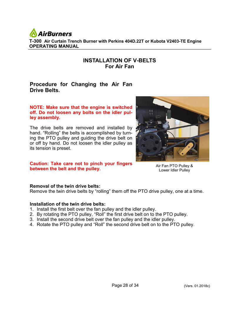
Procedure for Changing the Air Fan Drive Belts.
NOTE: Make sure that the engine is switched off. Do not loosen any bolts on the idler pul-ley assembly. The drive belts are removed and installed by hand. “Rolling” the belts is accomplished by turn-ing the PTO pulley and guiding the drive belt on or off by hand. Do not loosen the idler pulley as its tension is preset. Caution: Take care not to pinch your fingers between the belt and the pulley.
Removal of the twin drive belts: Remove the twin drive belts by “rolling” them off the PTO drive pulley, one at a time.
Installation of the twin drive belts: 1. Install the first belt over the fan pulley and the idler pulley. 2. By rotating the PTO pulley, “Roll” the first drive belt on to the PTO pulley. 3. Install the second drive belt over the fan pulley and the idler pulley. 4. Rotate the PTO pulley and “Roll” the second drive belt on to the PTO pulley.
INSTALLATION OF V-BELTS For Air Fan
Air Fan PTO Pulley & Lower Idler Pulley

Page 29 of 34 (Vers. 01.2018c)
T-300 Air Curtain Trench Burner with Perkins 404D.22T or Kubota V2403-TE Engine
OPERATING MANUAL
The technician/operator of the unit must take special care not to damage the manifold. Always load material from opposite the manifold. Do not drop logs on the manifold. Do not hit the manifold with the excavator bucket. Do not allow the manifold to be position directly in the flames. If at any time it becomes necessary to load material from the same side of the pit where the unit is placed, an assistant should help and warn the operator to watch for the assistants signals at all times when approaching the manifold. At no time should the loader’s wheels come closer than 6 inches from the manifold, and when beginning to dump the load, do so slowly. If you see anything that might fall on the manifold, you should stop and either re-position the loader or the load that is be-ing carried, in order to keep the material from hitting the manifold as it is dumped into the pit. IMPORTANT: In view of the fact that we are dealing with a tremendous amount of heat when the unit is operating properly, it is absolutely necessary to make sure the manifold is not hang-ing over the edge of the pit (See Page 8 “How to Set up the Machine”). The manifold is subjected to a great deal of heat during normal operations anyway, and if it is hanging over the edge of the pit it is exposed to a minimum of three times the normal heat which will cause severe deterioration of the manifold sections. Warpage due to heat is not covered under your warranty.
MAINTENANCE AND CARE OF MANIFOLD
Page 30 of 34 (Vers. 01.2018c)
T-300 Air Curtain Trench Burner with Perkins 404D.22T or Kubota V2403-TE Engine
OPERATING MANUAL
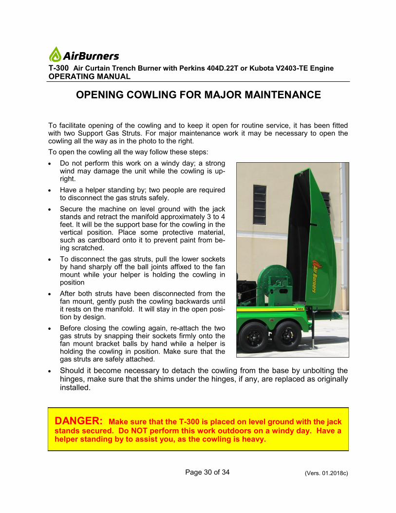
To facilitate opening of the cowling and to keep it open for routine service, it has been fitted with two Support Gas Struts. For major maintenance work it may be necessary to open the cowling all the way as in the photo to the right.
To open the cowling all the way follow these steps:
• Do not perform this work on a windy day; a strong wind may damage the unit while the cowling is up-right.
• Have a helper standing by; two people are required to disconnect the gas struts safely.
• Secure the machine on level ground with the jack stands and retract the manifold approximately 3 to 4 feet. It will be the support base for the cowling in the vertical position. Place some protective material, such as cardboard onto it to prevent paint from be-ing scratched.
• To disconnect the gas struts, pull the lower sockets by hand sharply off the ball joints affixed to the fan mount while your helper is holding the cowling in position
• After both struts have been disconnected from the fan mount, gently push the cowling backwards until it rests on the manifold. It will stay in the open posi-tion by design.
• Before closing the cowling again, re-attach the two gas struts by snapping their sockets firmly onto the fan mount bracket balls by hand while a helper is holding the cowling in position. Make sure that the gas struts are safely attached.
• Should it become necessary to detach the cowling from the base by unbolting the hinges, make sure that the shims under the hinges, if any, are replaced as originally installed.
DANGER: Make sure that the T-300 is placed on level ground with the jack stands secured. Do NOT perform this work outdoors on a windy day. Have a helper standing by to assist you, as the cowling is heavy.
OPENING COWLING FOR MAJOR MAINTENANCE

Page 31 of 34 (Vers. 01.2018c)
T-300 Air Curtain Trench Burner with Perkins 404D.22T or Kubota V2403-TE Engine
OPERATING MANUAL
SERVICING SPECIFICATIONS Parts List for Routine Service of
Kubota Industrial Diesel Engine - V3300-TE
Also Refer to Engine Manufacturer’s Service Manual for Engine Service Details (Engine should be serviced every 200 hours of operation)
Fuel Tank Capacity: Min. 65 Gallons *) Some 2006 V3300-TE engines are fitted with a 60A fuse
Rev. 0307B
Description Air Burners P/N Manufacturer’s P/N NAPA P/N
Air Filter (primary) 5000-1332 Donaldson P828889 6562
Air Filter (safety) 5000-1333 Donaldson P829333 6569
Oil Filter 5000-1326 Kubota IC020-32430 1068
Fuel Filter 5000-1299 Kubota 16631-43560 3393
Fuel/Water Separator Filter 5000-1297 Racor R20P -
V-Belt (Engine) 5000-1339 Kubota 1G521-97010 259400
Electrical System Fuse 60A Amp ID: Blue, Style: MAXI*
5000-0295 NAPA BK7822104 BK7822104
Electrical System Fuse 40A Amp ID: Green, Style: MAXI*
5000-0295 NAPA BK7822104 BK7822104
Optima Battery Red Top (12V, CCA 800, AH 50)
5000-0199 OPTIMA SC34A -
Engine Oil 15W40 Diesel Grade
Engine Coolant Low Silicon Anti-Freeze (Green) Units are shipped from factory with 50-50 mixture green antifreeze/water
Bearing Lubricant NLGI Grade 2
SERVICING SPECIFICATIONS Parts List for Routine Service of
Perkins Industrial Diesel Engine - 404D.22T
Refer to Engine Manufacturer’s Service Manual for Engine Service Details (Engine should be serviced first time after 50 hours and then every 250 hours of operation)
Description Air Burners P/N Manufacturer’s P/N
Air Filter (primary) 5000-2054 Donaldson P827653
Air Filter (safety) 5000-2055 Donaldson P829332
Oil Filter 5000-1323B Perkins 140517050
Fuel Filter 5000-1303A Perkins 26561117
V-Belt (Engine) 5000-1340 Perkins T80109107
V-Belt (Air Fan, 2 Belts) 5000-0008 Optibelt Redpower II
5V1400
CAT Battery (12V, CCA 580, AH 50)
5000-2050 CAT 8C-3612
Optima Battery Red Top (12V, CCA 800, AH 50)
5000-0199 OPTIMA SC34U
Tire Pressure 80 psi
Engine Oil 15W40 Diesel Grade
Engine Coolant Low Silicon Anti-Freeze (Green). Units are shipped from factory with 50-50 mixture green antifreeze/water.
Bearing Lubricant NLGI Grade 2
Fuel Tank Capacity Minimum 46 Gallons (174 Liters)
Consult Operating Manual for PTO and engine-to-fan coupler service and adjustment.
Contact Air Burners, Inc., should you require assistance with any maintenance tasks. Send Email to [email protected],
call 772-220-7303 or 888-566-3900.

Page 32 of 34 (Vers. 01.2018c)
T-300 Air Curtain Trench Burner with Perkins 404D.22T or Kubota V2403-TE Engine
OPERATING MANUAL
SERVICING SPECIFICATIONS Parts List for Routine Service of
Kubota Industrial Diesel Engine - V3300-TE
Also Refer to Engine Manufacturer’s Service Manual for Engine Service Details (Engine should be serviced every 200 hours of operation)
Fuel Tank Capacity: Min. 65 Gallons *) Some 2006 V3300-TE engines are fitted with a 60A fuse
Rev. 0307B
Description Air Burners P/N Manufacturer’s P/N NAPA P/N
Air Filter (primary) 5000-1332 Donaldson P828889 6562
Air Filter (safety) 5000-1333 Donaldson P829333 6569
Oil Filter 5000-1326 Kubota IC020-32430 1068
Fuel Filter 5000-1299 Kubota 16631-43560 3393
Fuel/Water Separator Filter 5000-1297 Racor R20P -
V-Belt (Engine) 5000-1339 Kubota 1G521-97010 259400
Electrical System Fuse 60A Amp ID: Blue, Style: MAXI*
5000-0295 NAPA BK7822104 BK7822104
Electrical System Fuse 40A Amp ID: Green, Style: MAXI*
5000-0295 NAPA BK7822104 BK7822104
Optima Battery Red Top (12V, CCA 800, AH 50)
5000-0199 OPTIMA SC34A -
Engine Oil 15W40 Diesel Grade
Engine Coolant Low Silicon Anti-Freeze (Green) Units are shipped from factory with 50-50 mixture green antifreeze/water
Bearing Lubricant NLGI Grade 2
SERVICING SPECIFICATIONS Parts List for Routine Service of
Kubota Industrial Diesel Engine - V3300-TE
Also Refer to Engine Manufacturer’s Service Manual for Engine Service Details (Engine should be serviced every 200 hours of operation)
Fuel Tank Capacity: Min. 65 Gallons *) Some 2006 V3300-TE engines are fitted with a 60A fuse
Rev. 0307B
Description Air Burners P/N Manufacturer’s P/N NAPA P/N
Air Filter (primary) 5000-1332 Donaldson P828889 6562
Air Filter (safety) 5000-1333 Donaldson P829333 6569
Oil Filter 5000-1326 Kubota IC020-32430 1068
Fuel Filter 5000-1299 Kubota 16631-43560 3393
Fuel/Water Separator Filter 5000-1297 Racor R20P -
V-Belt (Engine) 5000-1339 Kubota 1G521-97010 259400
Electrical System Fuse 60A Amp ID: Blue, Style: MAXI*
5000-0295 NAPA BK7822104 BK7822104
Electrical System Fuse 40A Amp ID: Green, Style: MAXI*
5000-0295 NAPA BK7822104 BK7822104
Optima Battery Red Top (12V, CCA 800, AH 50)
5000-0199 OPTIMA SC34A -
Engine Oil 15W40 Diesel Grade
Engine Coolant Low Silicon Anti-Freeze (Green) Units are shipped from factory with 50-50 mixture green antifreeze/water
Bearing Lubricant NLGI Grade 2
SERVICING SPECIFICATIONS Parts List for Routine Service of
Kubota Industrial Diesel Engine - V3300-TE
Also Refer to Engine Manufacturer’s Service Manual for Engine Service Details (Engine should be serviced every 200 hours of operation)
Fuel Tank Capacity: Min. 65 Gallons *) Some 2006 V3300-TE engines are fitted with a 60A fuse
Rev. 0307B
Description Air Burners P/N Manufacturer’s P/N NAPA P/N
Air Filter (primary) 5000-1332 Donaldson P828889 6562
Air Filter (safety) 5000-1333 Donaldson P829333 6569
Oil Filter 5000-1326 Kubota IC020-32430 1068
Fuel Filter 5000-1299 Kubota 16631-43560 3393
Fuel/Water Separator Filter 5000-1297 Racor R20P -
V-Belt (Engine) 5000-1339 Kubota 1G521-97010 259400
Electrical System Fuse 60A Amp ID: Blue, Style: MAXI*
5000-0295 NAPA BK7822104 BK7822104
Electrical System Fuse 40A Amp ID: Green, Style: MAXI*
5000-0295 NAPA BK7822104 BK7822104
Optima Battery Red Top (12V, CCA 800, AH 50)
5000-0199 OPTIMA SC34A -
Engine Oil 15W40 Diesel Grade
Engine Coolant Low Silicon Anti-Freeze (Green) Units are shipped from factory with 50-50 mixture green antifreeze/water
Bearing Lubricant NLGI Grade 2
SERVICING SPECIFICATIONS Parts List for Routine Service of
Kubota Industrial Diesel Engine - V3300-TE
Also Refer to Engine Manufacturer’s Service Manual for Engine Service Details (Engine should be serviced every 200 hours of operation)
Fuel Tank Capacity: Min. 65 Gallons *) Some 2006 V3300-TE engines are fitted with a 60A fuse
Rev. 0307B
Description Air Burners P/N Manufacturer’s P/N NAPA P/N
Air Filter (primary) 5000-1332 Donaldson P828889 6562
Air Filter (safety) 5000-1333 Donaldson P829333 6569
Oil Filter 5000-1326 Kubota IC020-32430 1068
Fuel Filter 5000-1299 Kubota 16631-43560 3393
Fuel/Water Separator Filter 5000-1297 Racor R20P -
V-Belt (Engine) 5000-1339 Kubota 1G521-97010 259400
Electrical System Fuse 60A Amp ID: Blue, Style: MAXI*
5000-0295 NAPA BK7822104 BK7822104
Electrical System Fuse 40A Amp ID: Green, Style: MAXI*
5000-0295 NAPA BK7822104 BK7822104
Optima Battery Red Top (12V, CCA 800, AH 50)
5000-0199 OPTIMA SC34A -
Engine Oil 15W40 Diesel Grade
Engine Coolant Low Silicon Anti-Freeze (Green) Units are shipped from factory with 50-50 mixture green antifreeze/water
Bearing Lubricant NLGI Grade 2
SERVICING SPECIFICATIONS Parts List for Routine Service of
Kubota Industrial Diesel Engine - V2403-TE
Refer to Engine Manufacturer’s Service Manual for Engine Service Details (Engine should be serviced first time after 50 hours and then every 200 hours of operation)
Description Air Burners P/N Manufacturer’s P/N
Air Filter (primary) 5000-1334 Donaldson P827653
Air Filter (safety) 5000-1229 Donaldson P829332
Oil Filter 5000-1327 Kubota 70000-32091
Fuel Filter 5000-1299 Kubota 16631-43560
Fuel/Water Separator Filter 5000-1297 Racor R20P
V-Belt (Engine) 5000-1341 Kubota 1G953-97010
V-Belt (Air Fan, 2 Belts) 5000-0008 Optibelt Redpower II
5V1400
Electrical System Fuse 40A Amp ID: Green, Style: MAXI
5000-0302 NAPA BK7821079
Optima Battery Red Top (12V, CCA 800, AH 50)
5000-0199 OPTIMA SC34U
CAT Battery (12V, CCA 580, AH 50)
5000-2050 CAT 8C-3612
Tire Pressure 80 psi
Engine Oil 15W40 Diesel Grade
Engine Coolant Low Silicon Anti-Freeze (Green). Units are shipped from factory with 50-50 mixture green antifreeze/water.
Bearing Lubricant NLGI Grade 2
Fuel Tank Capacity Minimum 46 Gallons (174 Liters)
Consult Operating Manual for PTO and engine-to-fan coupler service and adjustment.
Contact Air Burners, Inc., should you require assistance with any maintenance tasks. Send Email to [email protected],
call 772-220-7303 or 888-566-3900.

Page 33 of 34 (Vers. 01.2018c)
T-300 Air Curtain Trench Burner with Perkins 404D.22T or Kubota V2403-TE Engine
OPERATING MANUAL
Prior to towing a T-300, the following items should be checked and considered:
1. A suitable hitch assembly for the weight of the T-300 (Gross weight: 6,500 lbs., tongue weight: 890 lbs.) is required. The ball size is 2 5/16 inch. To use the pintle hitch, remove the ball hitch adapter plate fasted by three bolts.
2. The trailer is equipped with electric brakes on both axles. A suitable brake controller on the towing ve-hicle, such as a NAPA P/N 89241 or a Tekonsha P/N 9055, must be installed. The proper electrical connector (“pigtail”) must be used to electrically connect the towing vehicle to the trailer, in order for the brakes (and lights) to operate properly.
The T-300 has been fitted with a 7-blade RV type plug and a pig tail that is permanently attached to the T-300 tongue (see trailer-side pin diagram of the 7-pole receptacle on Page 34 “Trailer Wiring Diagram”).
3. The trailer tires are 8-ply bias tires, size 225/75D15 (originally supplied). The tires should be inflated to a (cold) pressure of 80 PSI.
4. Ensure that all lights are working properly.
5. Ensure that all machine components, such as the carrier-pipe/manifold assembly and cowl-ing are properly secured.
6. Ensure that trailer safely chains are connected to the tow-ing vehicle and that enough slack is allowed for turning.
7. Ensure the trailer hitch pin is locked with a spring clip or lock to prevent it from coming loose while traveling.
8. Periodic maintenance is required on the trailer axle bear-ings. Check with your dealer or the factory for mainte-nance schedule. All wheel lug nuts and safety chains should also be checked before each trip.
Ball hitch adapter, safety chains, pigtail, winch & front jack stand
IMPORTANT: Ensure that the retracted carrier-pipe/manifold assembly is se-cured with the appropriate locking device at the front end near the hitch to prevent it from sliding out of the back of the trailer while traveling. Also, make sure that the cowling latches are secure and the center “D” lift latch (handle) is locked in place with the provided key. Check all tires, wheel lug nuts, hitch assembly and safety chains.
T-300 TRAILER TOWING CHECKLIST
7-blade RV type plug

Page 34 of 34 (Vers. 01.2018c)
T-300 Air Curtain Trench Burner with Perkins 404D.22T or Kubota V2403-TE Engine
OPERATING MANUAL
Trailer Wiring Diagram T-300 (2016-2018 Models)